JP6460690B2 - Robot apparatus, robot control method, program, and recording medium - Google Patents
Robot apparatus, robot control method, program, and recording mediumDownload PDFInfo
- Publication number
- JP6460690B2 JP6460690B2JP2014187509AJP2014187509AJP6460690B2JP 6460690 B2JP6460690 B2JP 6460690B2JP 2014187509 AJP2014187509 AJP 2014187509AJP 2014187509 AJP2014187509 AJP 2014187509AJP 6460690 B2JP6460690 B2JP 6460690B2
- Authority
- JP
- Japan
- Prior art keywords
- force
- robot
- fitting
- control
- robot arm
- Prior art date
- Legal status (The legal status is an assumption and is not a legal conclusion. Google has not performed a legal analysis and makes no representation as to the accuracy of the status listed.)
- Active
Links
Images


Classifications
- B—PERFORMING OPERATIONS; TRANSPORTING
- B25—HAND TOOLS; PORTABLE POWER-DRIVEN TOOLS; MANIPULATORS
- B25J—MANIPULATORS; CHAMBERS PROVIDED WITH MANIPULATION DEVICES
- B25J9/00—Programme-controlled manipulators
- B25J9/16—Programme controls
- B25J9/1694—Programme controls characterised by use of sensors other than normal servo-feedback from position, speed or acceleration sensors, perception control, multi-sensor controlled systems, sensor fusion
- B—PERFORMING OPERATIONS; TRANSPORTING
- B25—HAND TOOLS; PORTABLE POWER-DRIVEN TOOLS; MANIPULATORS
- B25J—MANIPULATORS; CHAMBERS PROVIDED WITH MANIPULATION DEVICES
- B25J9/00—Programme-controlled manipulators
- B25J9/16—Programme controls
- B25J9/1679—Programme controls characterised by the tasks executed
- B25J9/1687—Assembly, peg and hole, palletising, straight line, weaving pattern movement
- G—PHYSICS
- G05—CONTROLLING; REGULATING
- G05B—CONTROL OR REGULATING SYSTEMS IN GENERAL; FUNCTIONAL ELEMENTS OF SUCH SYSTEMS; MONITORING OR TESTING ARRANGEMENTS FOR SUCH SYSTEMS OR ELEMENTS
- G05B2219/00—Program-control systems
- G05B2219/30—Nc systems
- G05B2219/39—Robotics, robotics to robotics hand
- G05B2219/39332—Adaptive force control
- G—PHYSICS
- G05—CONTROLLING; REGULATING
- G05B—CONTROL OR REGULATING SYSTEMS IN GENERAL; FUNCTIONAL ELEMENTS OF SUCH SYSTEMS; MONITORING OR TESTING ARRANGEMENTS FOR SUCH SYSTEMS OR ELEMENTS
- G05B2219/00—Program-control systems
- G05B2219/30—Nc systems
- G05B2219/40—Robotics, robotics mapping to robotics vision
- G05B2219/40032—Peg and hole insertion, mating and joining, remote center compliance
- G—PHYSICS
- G05—CONTROLLING; REGULATING
- G05B—CONTROL OR REGULATING SYSTEMS IN GENERAL; FUNCTIONAL ELEMENTS OF SUCH SYSTEMS; MONITORING OR TESTING ARRANGEMENTS FOR SUCH SYSTEMS OR ELEMENTS
- G05B2219/00—Program-control systems
- G05B2219/30—Nc systems
- G05B2219/41—Servomotor, servo controller till figures
- G05B2219/41144—Element used such as low pass filter to cut resonance at non needed regions
- Y—GENERAL TAGGING OF NEW TECHNOLOGICAL DEVELOPMENTS; GENERAL TAGGING OF CROSS-SECTIONAL TECHNOLOGIES SPANNING OVER SEVERAL SECTIONS OF THE IPC; TECHNICAL SUBJECTS COVERED BY FORMER USPC CROSS-REFERENCE ART COLLECTIONS [XRACs] AND DIGESTS
- Y10—TECHNICAL SUBJECTS COVERED BY FORMER USPC
- Y10S—TECHNICAL SUBJECTS COVERED BY FORMER USPC CROSS-REFERENCE ART COLLECTIONS [XRACs] AND DIGESTS
- Y10S901/00—Robots
- Y10S901/02—Arm motion controller
- Y10S901/09—Closed loop, sensor feedback controls arm movement
Landscapes
- Engineering & Computer Science (AREA)
- Robotics (AREA)
- Mechanical Engineering (AREA)
- Manipulator (AREA)
Description
Translated fromJapanese本発明は、ロボットアームの力制御に関するものである。 The present invention relates to force control of a robot arm.
産業用のロボットは、多関節のロボットアームと、ロボットアームの先端に取り付けられたロボットハンドとを有して構成されている。この種のロボットを用いた嵌合作業や作業対象物取得作業では、作業対象物の公差や設置誤差、ロボットハンド内で把持中の作業対象物の把持位置ズレなどが生じる。これにより、作業対象物とロボットハンドとの間に、ロボットアームからロボットハンドに延びる先端軸に対して交差する方向に位置ズレが発生する。 Industrial robots are configured to include an articulated robot arm and a robot hand attached to the tip of the robot arm. In the fitting work and work object acquisition work using this type of robot, tolerances and installation errors of the work object, gripping position shift of the work object being gripped in the robot hand, and the like occur. As a result, a displacement occurs between the work object and the robot hand in a direction intersecting the tip axis extending from the robot arm to the robot hand.
そのため、ロボットの各関節の角度を角度指令値に制御する位置制御のみ行うと、作業対象物とロボットハンドとの位置ズレにより、嵌合ミスや作業対象物取得ミスが発生する。そこで、ロボットがロボットハンドに作用する力を検出する力検出器を有し、制御装置によりロボットアームの力制御が行われている(特許文献1参照)。 For this reason, if only position control for controlling the angle of each joint of the robot to the angle command value is performed, a fitting error or a work object acquisition error occurs due to a positional shift between the work object and the robot hand. Therefore, the robot has a force detector that detects the force acting on the robot hand, and the force control of the robot arm is performed by a control device (see Patent Document 1).
力制御には、軌道補正の制御と到達位置検知の制御とがある。軌道補正の制御は、嵌合時やワーク取得時に、作業対象物とロボットハンドとの位置ズレにより発生する接触力が力検出器で検出され、先端軸に交差する方向に発生した接触力が小さくなる(0に近づく)ようにロボットアームの軌道を補正する制御である。到達位置検知の制御は、先端軸の延びる方向であるアプローチ方向の到達位置を検知して、ロボットアームを停止させる制御である。 Force control includes trajectory correction control and arrival position detection control. The control of the trajectory correction is such that the contact force generated by the displacement between the work object and the robot hand is detected by the force detector during fitting or workpiece acquisition, and the contact force generated in the direction intersecting the tip axis is small. This is control for correcting the trajectory of the robot arm so that The arrival position detection control is a control for detecting the arrival position in the approach direction, which is the direction in which the tip axis extends, and stopping the robot arm.
力検出器を有するロボットの構成では、ロボット動作時の振動等により、検出したい力以外の出力が力検出器の出力にノイズとして乗ることがある。力検出器の出力によって軌道補正の制御を行う際に、そのノイズの影響で補正が不安定になることがある。そのため、力検出器の出力にローパスフィルタをかけ、軌道補正の制御を行っている。 In the configuration of a robot having a force detector, an output other than the force to be detected may be added to the output of the force detector as noise due to vibration during the robot operation. When the trajectory correction is controlled by the output of the force detector, the correction may become unstable due to the noise. For this reason, a low-pass filter is applied to the output of the force detector to control trajectory correction.
しかし、到達位置検知の制御を行う際に、軌道補正の制御を行う場合と同様、力検出器の出力に同様の特性のフィルタを通して制御すると、到達時に発生する力を低い感度でしか検出することができない。そのため、ロボットアームを停止させるタイミングが遅くなる問題があった。ロボットアームを停止させるタイミングが遅くなると、ロボットハンドや力検出器、即ちロボットに過負荷がかかった状態で停止することがあった。 However, when the arrival position detection control is performed, the force generated at the time of arrival can be detected only with low sensitivity if the output of the force detector is controlled through a filter having the same characteristics as in the case of the trajectory correction control. I can't. Therefore, there is a problem that the timing for stopping the robot arm is delayed. When the timing for stopping the robot arm is delayed, the robot hand or force detector, that is, the robot may be stopped in an overloaded state.
逆に、到達位置検知の制御を優先して、高感度に力を検出するようにフィルタの特性を設定すれば、到達時に発生する力の過渡応答が速くなるので、ロボットへの過負荷を小さくすることは可能である。しかし、軌道補正の制御を行う際には、力検出結果に含まれる振動成分の除去が不十分であり、軌道の補正動作が不安定となっていた。 On the other hand, if priority is given to the control of the arrival position detection and the filter characteristics are set to detect the force with high sensitivity, the transient response of the force generated at the time of arrival will be faster, so the overload on the robot will be reduced. It is possible to do. However, when orbit correction control is performed, the vibration component included in the force detection result is not sufficiently removed, and the orbit correction operation is unstable.
そこで、本発明は、移動方向と交差する方向のロボットハンドの位置ズレを安定して補正し、かつ移動方向のロボットハンドの到達を迅速に検知することを目的とする。Accordingly, the present invention provides a positional deviation of the direction of the robot hand which intersectsthe moving direction stably corrected, and an object to quickly detect the arrival ofthe moving direction of the robot hand.
本発明のロボット装置は、多関節のロボットアームと、前記ロボットアームの先端に取り付けられたロボットハンドと、前記ロボットハンドに把持された把持物の移動方向の力としての第1検出力及び前記移動方向と交差する方向の力としての第2検出力を検出する力検出器と、前記ロボットアームの軌道データに基づき、前記把持物を前記移動方向にある対象物に向けて、離れた位置から移動作業を行うよう、前記ロボットアームの動作を制御する制御部と、を備え、前記制御部は、前記移動作業中、第1カットオフ周波数の第1ローパスフィルタにて、前記第1検出力に対してフィルタ処理を行う第1検出力補正処理と、前記移動作業中、前記把持物と前記対象物とが接触して前記第1検出力が閾値を上回ったときに前記ロボットハンドの前記移動方向への移動を停止させる第1力制御処理と、前記移動作業中、前記第1カットオフ周波数よりも周波数の低い第2カットオフ周波数の第2ローパスフィルタにて、前記第2検出力に対してフィルタ処理を行う第2検出力補正処理と、前記移動作業中、前記第2検出力が小さくなるように前記ロボットアームの軌道を前記移動方向とは交差する方向に補正する第2力制御処理と、を実行することを特徴とする。The robot apparatus according to the present invention includes an articulated robot arm, a robot hand attached to a tip of the robot arm, a first detection forceas aforce in a moving direction of a grasped object held by the robot hand, and themovement Based on the force detector for detecting the second detectionforce as the force in the direction crossing the direction and the trajectory data of the robot arm, thegrasped object is moved from the distant position toward the object in the moving direction. A control unit that controls the operation of the robot arm so as to perform an operation, and the control unit applies a first low-pass filter having a first cutoff frequency to the first detection force during themoving operation. a first detection power correcting process for performing filtering Te,the robot hand when themoving operation,the holding object and the object and the contact with said first detection power exceeds the threshold value A first force control processfor stopping the movement of the moving direction, themoving operation by the second lowpass filter of the second cut-off frequencylower frequency than the first cutoff frequency, said second detecting force And a second force for correctingthe trajectory of the robot arm in a direction crossing the moving direction so that the second detecting force isreduced during themoving operation. And a control process.
本発明によれば、感度の高い到達位置検知の制御と安定した軌道補正の制御とが同時に実施される。According to the present invention, the control of the control and stable orbit correction sensitive arrival position detectedRu are carried outsimultaneously.
以下、本発明を実施するための形態を、図面を参照しながら詳細に説明する。 Hereinafter, embodiments for carrying out the present invention will be described in detail with reference to the drawings.
[第1実施形態]
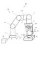
図1は、本発明の第1実施形態に係るロボット装置を示す模式図である。図2は、本発明の第1実施形態に係るロボット装置を示すブロック図である。図1に示すロボット装置100は、把持物と対象物との嵌合作業を行い組立部品Wを製造する製造方法を実行するものである。把持物及び対象物のうち、一方(第1実施形態では把持物)が、嵌合物W1であり、他方(第1実施形態では対象物)が、嵌合物W1が嵌合する穴H2を有する被嵌合物W2である。被嵌合物W2は、第1実施形態では、基台Bに載置されているものとするが、別のロボットに把持されていてもよい。嵌合物W1は、円柱状のピンであり、被嵌合物W2の穴H2は、嵌合物W1が嵌合する円柱状のピン穴である。[First Embodiment]
FIG. 1 is a schematic diagram showing a robot apparatus according to the first embodiment of the present invention. FIG. 2 is a block diagram showing the robot apparatus according to the first embodiment of the present invention. A
ロボット装置100は、多関節のロボット200と、ロボット200にケーブル等で接続されたロボットコントローラ300と、を備えている。 The
ロボット200は、多関節(例えば垂直多関節)のロボットアーム201と、エンドエフェクタであるロボットハンド202と、ロボットハンド202(フィンガ)に作用した力を検出する力検出器203と、を有している。ロボットアーム201は、複数のリンクが複数の関節J1〜J6で旋回又は回転可能に連結されて構成されている。ロボットアーム201の基端(基端リンク、ベース部ともいう)が基台Bの上面に固定されている。ロボットアーム201の先端(先端リンク、フランジ部ともいう)には、力検出器203を介してロボットハンド202が取り付けられている。なお、図1では、ロボットアーム201の先端リンクが力検出器203と一体に形成されている場合について図示しているが、先端リンクと力検出器203とが別体に形成されていて、力検出器203が先端リンクに固定具等で固定されている場合であってもよい。ロボットハンド202は、複数のフィンガを有し、嵌合物W1を把持又は把持解放することができるよう構成されている。The
ロボット200(ロボットアーム201)の基端には、ワールド座標系Σ0が設定されている。ワールド座標系Σ0は、基台Bに垂直なZ0軸と、Z0軸に対して交差(直交)し、互いに交差(直交)するX0軸及びY0軸とで規定されている。A world coordinate system Σ0 is set at the base end of the robot 200 (robot arm 201). The world coordinate system Σ0 is defined by a Z0 axis perpendicular to the base B, and an X0 axis and a Y0 axis that intersect (orthogonal) the Z0 axis and intersect (orthogonal) each other.
また、ロボット200(ロボットアーム201)の先端には、手先座標系Σ1が設定されている。手先座標系Σ1は、ロボットアーム201の先端からロボットハンド202に向かって延びる先端軸であるZ1軸と、Z1軸に対して交差(直交)し、互いに交差(直交)するX1軸及びY1軸とで規定されている。A hand coordinate system Σ1 is set at the tip of the robot 200 (robot arm 201). Hand coordinate system sigma1 includes aZ 1 axis which is distal shaft extending from the distal end of the
力検出器203は、いわゆる力覚センサであり、負荷されている力の大きさ及び方向を検出することがきるよう構成されている。即ち、力検出器203は、ロボットハンド202(フィンガ)に作用した、X1軸及びY1軸の方向の力(第2検出力)Fx,Fy、及びZ1軸の方向の力(第1検出力)Fzを検出する。The
またロボットアーム201は、各関節J1〜J6に対応して設けられた、各関節J1〜J6を駆動するモータ(図2)211と、各モータ211の回転位置を検出する位置検出器212と、各モータ211の回転を制御するモータ制御器213と、を有している。The
各モータ211は、ブラシレスDCモータやACモータ等のサーボモータである。各位置検出器212は、ロータリエンコーダで構成されている。各モータ制御器213は、各位置検出器212で検出した各関節J1〜J6の角度がロボットコントローラ300から取得した軌道、即ち角度指令値(位置指令値)となるように、各モータ211の回転を制御する。Each
図3は、本発明の第1実施形態に係るロボット装置100のロボットコントローラ300の構成を示すブロック図である。図3に示すように、ロボットコントローラ300は、コンピュータで構成されている。ロボットコントローラ300は、コンピュータの中枢となる制御部(演算部)としてのCPU(Central Processing Unit)301を備えている。また、ロボットコントローラ300は、記憶部として、ROM(Read Only Memory)302、RAM(Random Access Memory)303、及びHDD(Hard Disk Drive)304を備えている。また、ロボットコントローラ300は、記録ディスクドライブ305及び各種のインタフェース311〜314を備えている。 FIG. 3 is a block diagram showing a configuration of the
CPU301には、ROM302、RAM303、HDD304、記録ディスクドライブ305及びインタフェース311〜314が、バス310を介して接続されている。 A
ROM302には、BIOS等の起動プログラムが格納されている。RAM303は、CPU301の演算処理結果等、各種データを一時的に記憶する記憶装置である。HDD304には、プログラム321が格納(記録)される。そして、CPU301がプログラム321を読み出して実行することにより、図2に示す各部332,333,335,336,337,338として機能し、後述するロボット制御方法の各工程を実行する。なお、HDD304には、ユーザにより作成されたロボット動作プログラム320が格納される。記録ディスクドライブ305は、記録ディスク322に記録された各種データやプログラム等を読み出すことができる。 The
インタフェース311には、ロボット200の各モータ制御器213が接続されている。CPU301は、バス310及びインタフェース311を介して、各モータ制御器213に、関節J1〜J6の角度指令値(位置指令値)を出力し、ロボット200の動作を制御する。Each
インタフェース312には、マウスやキーボード等、作業者が操作して、操作に応じた指令をCPU301に送信する入力装置600が接続されている。インタフェース313には、画像を表示するディスプレイ等の表示装置700が接続されている。インタフェース314には、USBメモリ等の書き換え可能な不揮発性メモリ、或いは外付けHDD等の外部記憶装置800が接続されている。 The
CPU301は、軌道データに基づき、ロボットハンド202に把持された嵌合物W1と被嵌合物W2との嵌合作業を行うようロボット200(ロボットアーム201)の動作を制御する。CPU301, based on the trajectory data, to control the operation of the robot 200 (robot arm 201) to perform a fitting operation between the mating objectW 1 gripped by the
軌道データは、CPU301が、ロボット動作プログラム320に基づいて生成する。ロボット動作プログラム320は、ロボット200に対してどのような動きをさせるかを指示する動作指示であり、ロボット専用のプログラミング言語を用いてユーザにより作成されたプログラムである。ロボット200に何らかの動作を行わせる際には、ロボット動作プログラム320内で位置制御や力制御などの制御方法や位置、速度、力目標値等のパラメータをプログラムし、動作の指示を行う。 The trajectory data is generated by the
CPU301は、図3に示すプログラム321を実行することにより、図2に示す軌道計算部332、位置出力部333、軌道補正計算部335、軌道補正フィルタ部336、到達位置判定部337及び到達位置判定フィルタ部338として機能する。 The
軌道計算部332は、ロボット動作プログラム320に記載されている情報をもとに、ロボット200(ロボットアーム201)の経路を作成し、ロボット200の経路に基づいて、ロボット200(ロボットアーム201)の軌道を生成する。 The
ここで、ロボット200の経路とは、ロボット200の各関節J1〜J6の軌跡である。換言すれば、ロボット200の経路とは、関節J1〜J6の角度を座標軸とした関節空間における点(ポーズ)の順序集合である。ロボット200の軌道とは、時間をパラメータとしてポーズ(経路)を表したものであり、第1実施形態では、所定時間(例えば2ms)間隔のロボット200の関節J1〜J6の角度指令値の集合である。Here, the path of the
ここで、CPU301によるロボットアーム201の動作の制御は、大別して、位置制御と力制御の2つの方法がある。 Here, the control of the operation of the
位置制御は、ロボット動作プログラム320により生成した軌道に従ってロボットアーム201を動作させる制御である。力制御は、ロボット動作プログラム320により生成した軌道に従ってロボットアーム201を動作させているときに、力検出器203により検出された力Fx,Fy,Fzに基づいて動作を修正する制御である。 The position control is control for operating the
また、力制御は、軌道補正の制御と到達位置検知の制御とがある。軌道補正の制御は、第2検出力である力Fx,Fyが小さくなるように(0に近づくように)ロボットハンド202をX1軸,Y1軸の方向に移動させて、ロボットアーム201の軌道を補正する制御である。到達位置検知の制御は、第1検出力である力Fzに対して閾値判定を行い、力Fzが閾値を上回ったときにロボットハンド202のZ1軸の方向の移動を停止させる制御である。The force control includes trajectory correction control and arrival position detection control. The trajectory correction control is performed by moving the
ユーザは、CPU301(ロボットコントローラ300)に位置制御でロボット200を制御させる際は、位置制御を行う旨をロボット動作プログラム320に記載する。軌道計算部332は、このように記述されたロボット動作プログラム320に基づき、目標位置までの軌道を生成する。 When the user causes the CPU 301 (robot controller 300) to control the
位置出力部333は、生成された軌道(角度指令値)を、所定時間(例えば2ms)毎にモータ制御器213に通知する。モータ制御器213は、位置出力部333から受領した軌道と位置検出器212から取得した現在位置を用いてモータ211をフィードバック制御する。 The
この位置制御の際には、図2に示す軌道補正計算部335、軌道補正フィルタ部336、到達位置判定部337及び到達位置判定フィルタ部338は機能しない。 During this position control, the trajectory
次に、ユーザは、CPU301(ロボットコントローラ300)に力制御でロボット200を制御させる際は、力制御を行う旨をロボット動作プログラム320に記載する。ロボット動作プログラム320内では、到達位置検知の制御や軌道補正の制御の力制御を実施する旨が記載される。 Next, when the user causes the CPU 301 (robot controller 300) to control the
CPU301は、記載されたロボット動作プログラム320の情報を解析する。到達位置判定フィルタ部338は、ロボット動作プログラム320内で到達位置検知の制御が指定された場合に、ロボット動作プログラム320で指定されたローパスフィルタを設定する。軌道補正フィルタ部336は、ロボット動作プログラム320内で軌道補正の制御が指定された場合に、ロボット動作プログラム320で指定されたローパスフィルタを設定する。第1実施形態では、嵌合物W1と被嵌合物W2との嵌合作業を行う際には、軌道補正の制御及び到達位置検知の制御の両方を同時に実行する。The
軌道補正フィルタ部336及び到達位置判定フィルタ部338は、力検出器203で出力された力Fx,Fy,Fzのデータの高周波のノイズ成分をカットするためのローパスフィルタ(デジタルフィルタ)として機能する。各フィルタ部336,338は、カットオフ周波数FC1,FC2がパラメータとして指定され、そのパラメータはロボット動作プログラム320内で記載することができる。具体的には、軌道補正フィルタ部336は、第2カットオフ周波数であるカットオフ周波数FC1の第2ローパスフィルタとして動作し、力Fx,Fyに対してフィルタ処理を行う。到達位置判定フィルタ部338は、嵌合作業中、第1カットオフ周波数であるカットオフ周波数FC2の第1ローパスフィルタとして動作し、力Fzに対してフィルタ処理を行う。The trajectory
軌道計算部332は、力制御が指定された場合、ロボット動作プログラム320に記載された動作指示通りに、位置制御と同様な方法で軌道を生成する。位置出力部333は、所定時間(例えば2ms)毎に角度指令値をモータ制御器213に通知する。モータ制御器213は、モータ211の回転をフィードバック制御し、ロボット200を動作させる。 When the force control is designated, the
同時に、各フィルタ部336,338は、力検出器203よりロボット200にかかる力Fx,Fy,Fzを取得する。具体的には、軌道補正フィルタ部336は力Fx,Fyを取得し、到達位置判定フィルタ部338は力Fzを取得する。 At the same time, the
軌道補正フィルタ部336は、嵌合作業中、カットオフ周波数FC1の第2ローパスフィルタを用いて、力Fx,Fyに対してフィルタ処理を行う(第2検出力補正処理、第2検出力補正工程)。同時に、到達位置判定フィルタ部338は、嵌合作業中、カットオフ周波数FC2の第1ローパスフィルタを用いて、力Fzに対してフィルタ処理を行う(第1検出力補正処理、第1検出力補正工程)。The trajectory
軌道補正計算部335は、軌道補正フィルタ部336を通して取得した力Fx,Fyのデータに合わせた(比例する)軌道補正量を計算し、軌道計算部332で計算した軌道に加えることで、軌道を補正する。即ち、軌道補正計算部335は、嵌合作業中、力Fx,Fyが小さくなるように(0に近づくように)ロボットハンド202をX1軸,Y1軸の方向に移動するよう、ロボットアーム201の軌道を補正する(第2力制御処理、第2力制御工程)。The trajectory
位置出力部333は、補正された軌道データ(補正された角度指令値)をモータ制御器213に通知する。これにより、モータ制御器213は、補正された軌道データに基づいてモータ211の回転を制御する。このように、CPU301は、力制御による軌道補正の制御を実施する。 The
一方、到達位置判定部337は、ロボット動作プログラム320に記載された力目標値(閾値)と到達位置判定フィルタ部338を通して取得した力Fzのデータとを比較する。そして、到達位置判定部337は、力Fzが力目標値(閾値)を上回ったタイミングで位置出力部333にロボットハンド202がZ1軸の方向に移動するのを停止させる停止指令を通知する。即ち、到達位置判定部337は、嵌合作業中、力Fzに対して閾値判定を行い、力Fzが閾値を上回ったときにロボットハンド202のZ1軸の方向の移動が停止するようロボットアーム201の動作を制御する(第1力制御処理,第1力制御工程)。On the other hand, the reaching
第1実施形態では、到達位置判定部337は、ロボットハンド202のX1軸の方向及びY1軸の方向の移動も停止するよう停止指令を通知する。つまり、第1実施形態では、停止指令はロボットアーム201の動作を停止させる指令である。In the first embodiment, the arrival
位置出力部333は、停止指令を受信したタイミングで各モータ制御器213へ停止するよう通知し、各モータ制御器213はモータ211を停止させる。このように、CPU301は、力制御による到達位置検知の制御を実施する。 The
ここで、位置出力部333から停止指令をモータ制御器213が受信した際、モータ211を即停止させず、モータ制御器213が各モータ211を減速させて停止しても良い。また、位置出力部333で到達位置判定部337から停止指令を受信した際に、軌道計算部332を通して減速軌道を計算し、算出された軌道をモータ制御器213に通知して、停止させても良い。 Here, when the
次に、ロボットコントローラ300によるロボットハンド202が嵌合物W1を把持し、嵌合物W1を被嵌合物W2の穴H2に嵌合させる嵌合作業を行う場合の力制御について、具体的に説明する。図4は、嵌合物W1と被嵌合物W2との嵌合作業を行っている状態を示す説明図である。Next, the power control when the
図4に示すように、被嵌合物W2の穴H2は、凹み穴であり、底部B2が形成されている。穴H2の開口端には、嵌合物W1を誘い込むための面取り部C2が形成されている。なお、面取り部は、嵌合物W1及び被嵌合物W2のうち少なくとも一方に形成されていればよく、嵌合物W1に面取り部が形成されていても、嵌合物W1と被嵌合物W2の両方に面取り部が形成されていてもよい。As shown in FIG. 4, the holes of H2 the fitted object W2 is a recessed hole, the bottom B2 are formed. A chamfered portion C2 for guiding the fitting W1 is formed at the opening end of the hole H2 . Incidentally, the chamfered portion may be formed on at least one of Hamagobutsu W1 and the fitted object W2, even if the chamfered portion is formed on Hamagobutsu W1, Hamagobutsu W1 and may be chamfered portion is formed on both the fitted object W2.
嵌合物W1と被嵌合物W2はそれぞれ、不図示の供給装置により供給され、取得位置に供給された嵌合物W1をロボットハンド202で把持し、被嵌合物W2は組付け位置に供給される。The fitting object W1 and the fitting object W2 are respectively supplied by a supply device (not shown), the fitting object W1 supplied to the acquisition position is gripped by the
このような供給方法をとると、ロボットハンド202に対する嵌合物W1の位置ズレや、被嵌合物W2の組み付け位置に対する位置ズレにより、被嵌合物W2に対する嵌合物W1の相対的な位置ズレが生じることがある。また、嵌合物W1及び被嵌合物W2は製作時の公差分バラつきが生じている。Taking such a supplying method, positional deviation and the fitting thereof W1 for the
上記の要因から被嵌合物W2に対する嵌合物W1の組付け方向(図4に示すZ1軸の方向)と組付け方向に鉛直な面方向(図4に示すX1,Y1軸の方向)それぞれの相対位置ズレが生じる。位置制御だけで嵌合作業を行うと、被嵌合物W2の穴H2に嵌合物W1が嵌合されない場合がある。X1 shown in (Z1 axial direction shown in FIG. 4) and assembled vertical plane in the direction (Figure 4 assembly direction fitting product W1 for the fitted object W2 from the abovefactors, Y1 Axial direction) Each relative position shift occurs. Doing fitting operation in the position control only, there is a case where the fitting was W1 into the hole of H2 the fitted object W2 is not engaged.
そのため、第1実施形態では、穴H2の中心軸に対する嵌合物W1の中心軸の、X1,Y1軸の方向の相対的なズレΔX,ΔYを補正する軌道補正の制御と、Z1軸の方向の到達位置検知の制御の2つの力制御を同時に行う。Therefore, in the first embodiment, control of trajectory correction for correcting relative deviations ΔX and ΔY in the directions of the X1 and Y1 axes of the center axis of the fitting W1 with respect to the center axis of the hole H2 ; Two force controls of the arrival position detection control in the direction of the Z1 axis are simultaneously performed.
ここで、デジタルフィルタを介した力検出の感度は、デジタルフィルタのカットオフ周波数で決まる。即ち、カットオフ周波数を高い周波数にするほど、感度が高くなり、逆にカットオフ周波数を低い周波数にするほど、感度が低くなる。 Here, the sensitivity of force detection via the digital filter is determined by the cutoff frequency of the digital filter. That is, the higher the cutoff frequency is, the higher the sensitivity is. On the contrary, the lower the cutoff frequency is, the lower the sensitivity is.
到達位置検知の制御を実施する際に、仮に接触したことを検知する感度が低い場合、嵌合物W1を底部B2に押し付け続けることとなり、ロボットハンド202と力検出器203、即ちロボット200に過負荷がかかった状態を維持し続けることとなる。When the arrival position detection control is performed, if the sensitivity for detecting contact is low, the fitting W1 is continuously pressed against the bottom B2 , and the
そこで、第1実施形態では、到達位置検知の制御に使用する到達位置判定フィルタ部338におけるローパスフィルタのカットオフ周波数FC2を、カットオフ周波数FC1よりも高い周波数に設定し、急峻な力の変化を検知できるような設定とする。Therefore, in the first embodiment, the cutoff frequency FC2 of the low pass filter in the arrival position
また、嵌合物W1と被嵌合物W2の穴H2とのX1,Y1軸の方向のズレを補正するための軌道補正の制御では、相対位置ズレの影響で、嵌合物W1の下端が面取り部C2に接触することで、X1,Y1軸の方向に力Fx,Fyが発生する。その発生した力Fx,Fyを力検出器203で検出し、軌道補正計算部335は、軌道補正の制御を実施する。Further, in the trajectory correction control for correcting the displacement of the fitting object W1 and the hole H2 of the fitting object W2 in the X1 and Y1 axis directions, the fitting is caused by the influence of the relative position deviation. When the lower end of the object W1 contacts the chamfered portion C2 , forces Fx and Fy are generated in the directions of the X1 and Y1 axes. The generated forces Fx and Fy are detected by the
ここで、力検出器203はロボット200に設置されているため、面取り部C2に接触して発生した力以外もロボット200(ロボットアーム201)の振動によるノイズが同時に検出される。そのため、軌道補正フィルタ部336で使用するローパスフィルタのカットオフ周波数FC1をカットオフ周波数FC2よりも低い周波数に設定し、力の急峻な変化を無視するような設定とする。Here,
例えば、カットオフ周波数FC1を20Hzに設定し、カットオフ周波数FC2を100Hzに設定する。これらカットオフ周波数FC1,FC2は、実験を行って決定すればよい。For example, the cut-off frequency FC1 is set to 20 Hz, and the cut-off frequency FC2 is set to 100 Hz. These cut-off frequencies FC1 and FC2 may be determined through experiments.
以上、第1実施形態によれば、軌道補正フィルタ部336に使用する第2ローパスフィルタと、到達位置判定フィルタ部338に使用する第1ローパスフィルタとを別々に設定している。そして、第1ローパスフィルタのカットオフ周波数FC2を第2ローパスフィルタのカットオフ周波数FC1よりも高い周波数に設定している。As described above, according to the first embodiment, thesecond low-pass filter used for the trajectory
これにより、軌道補正の制御では、軌道補正フィルタ部336によって、力検出器203により検出された力Fx,Fyにおいて周波数FC1以上の高周波のノイズがカットされる。したがって、安定した軌道補正を実施することができる。Accordingly, in the trajectory correction control, the trajectory
また、到達位置検知の制御では、軌道補正フィルタ部336により、力検出器203により検出された力Fzにおいて、周波数FC2以上の周波数のノイズはカットされ、周波数FC1〜FC2の周波数成分については、カットされずに残っている。よって、軌道補正フィルタ部336に用いるフィルタよりも感度良く力を検出することができる。これにより、Z1軸方向の到達位置に達した時に発生する力Fzを感度よく検知することが可能になる。Further, in the control of the reached position detection, the trajectory
このように、感度の高い到達位置検知の制御と安定した軌道補正の制御とが同時に実施されるので、嵌合物W1と被嵌合物W2との安定した嵌合作業を実現することが可能になる。Thus, since the control of the control and stable trajectory correction with high sensitivity arrival position detection is performed at the same time, to realize a stable fitting operation between Hamagobutsu W1 and the fitted object W2 Is possible.
[第2実施形態]
次に、本発明の第2実施形態に係るロボット装置によるロボット制御について説明する。図5は、本発明の第2実施形態に係るロボット装置を示す模式図である。なお、第2実施形態のロボット装置は、上記第1実施形態のロボット装置と同様の構成であるため、同一符号を付して説明を省略する。第2実施形態では、嵌合を行う嵌合物及び被嵌合物の形状が上記第1実施形態と異なる。なお、ロボットハンド202は、ロボットアーム201の先端リンクが関節J6で回転することによりZ1軸を中心に回転する。[Second Embodiment]
Next, robot control by the robot apparatus according to the second embodiment of the present invention will be described. FIG. 5 is a schematic diagram showing a robot apparatus according to the second embodiment of the present invention. Note that the robot apparatus according to the second embodiment has the same configuration as the robot apparatus according to the first embodiment, and thus the same reference numerals are given and description thereof is omitted. In the second embodiment, the shapes of the fitting object to be fitted and the fitting object are different from those of the first embodiment. Incidentally, the
嵌合物W10は、円柱状の円柱部W11と、円柱部W11の中心軸の延びる方向の先端部と後端部との間の中間部における外周面に突設された突起部であるボスW12と、を有している。被嵌合物W20には、穴H20が形成されている。穴H20は、円柱部W11が嵌合する円柱状の円柱穴H21と、円柱穴H21に繋がり、ボスW12が嵌合する溝であるボス穴H22と、を有している。Hamagobutsu W10 includes a cylindrical columnar portion W11, with protrusions projecting from the outer peripheral surface of the intermediate portion between the direction of the distal end portion and a rear end of extension of the central axis of the cylindrical portion W11 It has a certain bossW 12, a. In the fitted objectW 20 is a holeH 20 is formed. HolesH 20 has a cylindrical cylinder boreH 21 of the cylindrical portionW 11 is fitted, connected to the cylindrical boreH 21, has a boss holeH 22 is a groove bossW 12 is fitted, the .
第2実施形態では、ロボットハンド202が把持する把持物が、嵌合物W10であり、対象物が被嵌合物W20である。第2実施形態では、嵌合作業として、円柱部W11を円柱穴H21に嵌合させ、かつボスW12をボス穴H22に嵌合させる作業を行う。In the second embodiment, grasped by the
以下、嵌合物W10の回転し押し付けながらボスW12をボス穴H22に嵌合させる動作について説明する。Hereinafter, the operation of fitting the bossW 12 while pressing and rotation of HamagobutsuW 10 in the boss holeH 22.
CPU301は、ロボットハンド202によってボスW12を有した嵌合物W10を把持させ、ロボットハンド202が把持している嵌合物W10を被嵌合物W20に設けられた穴H20に嵌合する嵌合作業を行う。この嵌合作業はボスW12をボス穴H22に嵌合することで完了する。CPU301 causes the gripping engagement wasW 10 having a bossW 12 by the
円柱穴H21は上記第1実施形態の穴H2と同様の凹み穴であり、円柱穴H21の開口端に、円柱部W11の先端部を誘い込むための面取り部が形成されている。なお、面取り部は、円柱部W11及び円柱穴H21のうち少なくとも一方に形成されていればよく、円柱部W11に面取り部が形成されていても、円柱部W11と円柱穴H21の両方に面取り部が形成されていてもよい。Cylindrical holes H21 are the same recessed holes and the holes of H2 the first embodiment, the open end of the cylindrical bore H21, chamfer for lure tip of the cylindrical portion W11 is formed. Incidentally, the chamfered portion may be formed on at least one of the cylindrical portion W11 and the cylindrical bore H21, even if the chamfered portion to the cylindrical portion W11 is formed, the cylindrical portion W11 and cylindrical hole H21 Both of them may be chamfered.
また、嵌合物W10及び被嵌合物W20は、上記第1実施形態と同様の方法で供給される。また、嵌合物W10及び被嵌合物W20の公差、嵌合物W10の把持位置、被嵌合物W20の設置位置の影響で、被嵌合物W20に対して嵌合物W10に相対位置のズレが生じる。このため、第2実施形態においても、到達位置検知の制御と軌道補正の制御の2つの力制御で嵌合作業を行う。Further, Hamagobutsu W10 and the fitted object W20 is fed in the same way as the first embodiment. Further, the tolerance of HamagobutsuW 10 and the fitted objectW 20, the gripping position of HamagobutsuW 10, the influence of the installation position of the fitted objectW 20, fitted against the fitted objectW 20 displacement of the relative position occur at the objectW 10. For this reason, also in the second embodiment, the fitting operation is performed by two force controls of the arrival position detection control and the trajectory correction control.
ここで、ボスW12は、円柱部W11の先端部(下端部)より一定距離上方に離れた場所に取り付けられている。Here, the boss W12 is mounted at a location spaced a predetermined distance above the distal end (lower end) of the cylindrical portion W11.
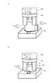
図6は、本発明の第2実施形態における嵌合物W10と被嵌合物W20との嵌合作業を説明するための説明図である。図6(a)は、嵌合作業の途中状態を示し、図6(b)は、嵌合作業の終了状態を示している。FIG. 6 is an explanatory diagram for explaining a fitting operation between the fitting object W10 and the fitting object W20 in the second embodiment of the present invention. FIG. 6A shows an intermediate state of the fitting operation, and FIG. 6B shows an end state of the fitting operation.
CPU301は、図6(a)に示すように、円柱部W11の先端部を穴H20の円柱穴H21に嵌合する工程を実施した後、図6(b)に示すように、ボスW12をボス穴H22に嵌合するために位相を合わせて嵌合する2つの工程を実施する。CPU301, as shown in FIG. 6 (a), after performing the step of fitting the tip of the cylindrical portionW 11 in a cylindrical holeH 21 of the holeH 20, as shown in FIG. 6 (b), the boss In order to fit W12 to the boss hole H22 , two steps of fitting in phase are performed.
まず、図6(a)に示す円柱部W11の先端部を穴H20に嵌合する処理は、上記第1実施形態に記載の内容とほぼ同様の方法で嵌合作業を行うため、詳細な説明は省略する。上記第1実施形態と異なる点として、第2実施形態では、CPU301は、到達位置検知の制御により、ボスW12を被嵌合物W20上面に接触させたとき、ロボットアーム201の動作を停止させる点である。即ち、到達位置判定部337は、嵌合作業中、円柱部W11の先端部を円柱穴H21に嵌合させて、力Fzが閾値を上回ったとき、嵌合物W10のZ1軸の方向の移動を停止させる。First, the process of fitting the tip of the cylindrical portion W11 shown in FIG. 6 (a) into the hole H20 in order to perform a fitting operation in much the same way as the contents described in the first embodiment, details The detailed explanation is omitted. As a difference from the first embodiment, in the second embodiment, the
次に、CPU301は、ボスW12をボス穴H22に嵌合させる際に、図6(b)に示すように、ロボットハンド202で把持している嵌合物W10の円柱部W11の先端部を円柱穴H21に嵌合させている状態で、嵌合物W10をZ1軸まわりに回転させる。Next,
即ち、CPU301は、嵌合作業中、円柱部W11の先端部を円柱穴H21に嵌合させて第1力制御処理にて嵌合物W10のZ1軸方向の移動を停止させたとき、力Fzが閾値を下回るまで、嵌合物W10を、Z1軸を中心に回転させる。具体的には、ロボットハンド202をロボットアーム201に対してZ1軸を中心に回転させる。That,
ボスW12がボス穴H22に到達すると、ボス穴H22に到達したタイミングでZ1軸方向の力Fzが抜け、力Fzが閾値を下回る。その力Fzを到達位置検知の力制御で検知することで、ボスW12をボス穴H22に嵌合するための位相が検知可能になる。When the bossW 12 reaches the boss holeH 22, missingZ 1 axial force Fz in timing reaches the boss holesH 22, the force Fz is below a threshold. By detecting the force Fz in the force control of the arrival position detection, the phase for fitting the bosses W12 in the boss hole H22 becomes detectable.
ここで、ボス穴H22の位相を検知する際、仮に到達位置検知の感度が低いと、組付け位相に到達しても閾値を下回る力を検知せずに通り過ぎてしまい、ボス穴H22の位相を検知することができなくなるおそれがある。そのため、上記第1実施形態と同様、到達位置検知に使用する到達位置判定フィルタ部338で使用するフィルタのカットオフ周波数FC2をカットオフ周波数FC1よりも大きく設定し、急峻な力の変化を検知できるような設定とする。その後、検知した位相で嵌合物W10をZ1軸の方向に押し込んで、再度、閾値判定を行うことにより、嵌合物W10を穴H20に嵌合する嵌合作業が完了する。Here, when detecting the phase of the boss hole H22 , if the sensitivity of detection of the arrival position is low, even if the assembly phase is reached, the force passing below the threshold is not detected, and the boss hole H22 is detected. There is a possibility that the phase cannot be detected. Therefore, as in the first embodiment, the cutoff frequency FC2 of the filter used in the arrival position
ここで、嵌合物W10を回転させる際、嵌合物W10を回転させる回転軸と穴H20の回転軸にズレが生じている場合、回転中にX1,Y1軸の方向の力Fx,Fyが生じることがある。Here, when rotating the Hamagobutsu W10, if the deviation in the rotating axis of the rotary shaft and the hole H20 to rotate the Hamagobutsu W10 occurs, during rotation X1, Y1 axially of Forces Fx and Fy may occur.
よって、第2実施形態では、ロボットハンド202と力検出器203、即ちロボット200に過負荷がかかるのを回避するため、嵌合物W10を回転させるのと同時に、回転軸のズレを補正するための軌道補正の制御を実施する。Therefore, in the second embodiment, in order to avoid the
この軌道補正の制御では、回転時のロボット200の振動によるノイズを検出し、嵌合物W10と穴H20が接触することによって発生する力以外の力も同時に検出する。そのため、上記第1実施形態と同様、軌道補正フィルタ部336で使用するフィルタのカットオフ周波数FC1を小さくし、力の急峻な変化を無視するような設定とする。The orbit control correction detects noise caused by vibration of the
以上の如くカットオフ周波数FC1,FC2を設定することで、感度の高い到達位置検知によりボスW12を組付ける位相を検知するのと同時に、嵌合物W10と穴H20との相対位置ズレにより発生する回転軸のズレを吸収した嵌合作業を実現できる。By setting the cutoff frequencies FC1 and FC2 as described above, the phase at which the boss W12 is assembled is detected by detecting the arrival position with high sensitivity, and at the same time, the relative relationship between the fitting W10 and the hole H20 is detected. A fitting operation that absorbs the displacement of the rotating shaft caused by the displacement can be realized.
なお、本発明は、以上説明した実施形態に限定されるものではなく、本発明の技術的思想内で多くの変形が可能である。 The present invention is not limited to the embodiment described above, and many modifications are possible within the technical idea of the present invention.
上記第2実施形態では、力Fzを検知して到達位置検知を実施したが、力Fzだけでなく、力Fzの時間変化量を使用して、到達位置検知を実施しても良い。また、上記第2実施形態で使用した到達位置検知では、挿入方向の力Fzをモニタリングして検知していたが、Z軸まわりの回転方向の力成分を利用して、到達位置検知を実施してもよい。 In the second embodiment, the arrival position is detected by detecting the force Fz. However, the arrival position may be detected using not only the force Fz but also the time variation of the force Fz. In the arrival position detection used in the second embodiment, the force Fz in the insertion direction is monitored and detected. However, the arrival position is detected using the force component in the rotation direction around the Z axis. May be.
上記第1,第2実施形態では、ロボットハンドが嵌合物を把持して嵌合物と被嵌合物との嵌合作業を行う場合について説明したが、これに限定するものではない。ロボットハンドが被嵌合物を把持して嵌合作業を行う場合であっても本発明は適用可能である。 In the first and second embodiments, the case where the robot hand grasps the fitting object and performs the fitting operation between the fitting object and the fitting object is described, but the present invention is not limited to this. The present invention is applicable even when the robot hand grips the object to be fitted and performs the fitting work.
上記実施形態の各処理動作は具体的にはCPU301により実行されるものである。従って上述した機能を実現するプログラムを記録した記録媒体をロボットコントローラに供給し、ロボットコントローラを構成するコンピュータが記録媒体に格納されたプログラムを読み出し実行することによって達成されるようにしてもよい。この場合、記録媒体から読み出されたプログラム自体が上述した実施形態の機能を実現することになり、プログラム自体及びそのプログラムを記録した記録媒体は本発明を構成することになる。 Each processing operation of the above embodiment is specifically executed by the
また、上記実施形態では、コンピュータ読み取り可能な記録媒体がHDD304であり、HDD304にプログラム321が格納される場合について説明したが、これに限定するものではない。プログラムは、コンピュータ読み取り可能な記録媒体であれば、いかなる記録媒体に記録されていてもよい。例えば、プログラムを供給するための記録媒体としては、図3に示すROM302、記録ディスク322、外部記憶装置800等を用いてもよい。具体例を挙げて説明すると、記録媒体として、フレキシブルディスク、ハードディスク、光ディスク、光磁気ディスク、CD−ROM、CD−R、磁気テープ、書き換え可能な不揮発性のメモリ(例えばUSBメモリ)、ROM等を用いることができる。 In the above embodiment, the computer-readable recording medium is the
また、上記実施形態におけるプログラムを、ネットワークを介してダウンロードしてコンピュータにより実行するようにしてもよい。 Further, the program in the above embodiment may be downloaded via a network and executed by a computer.
また、コンピュータが読み出したプログラムコードを実行することにより、上記実施形態の機能が実現されるだけに限定するものではない。そのプログラムコードの指示に基づき、コンピュータ上で稼働しているOS(オペレーティングシステム)等が実際の処理の一部または全部を行い、その処理によって前述した実施形態の機能が実現される場合も含まれる。 Further, the present invention is not limited to the implementation of the functions of the above-described embodiment by executing the program code read by the computer. This includes a case where an OS (operating system) or the like running on the computer performs part or all of the actual processing based on the instruction of the program code, and the functions of the above-described embodiments are realized by the processing. .
さらに、記録媒体から読み出されたプログラムコードが、コンピュータに挿入された機能拡張ボードやコンピュータに接続された機能拡張ユニットに備わるメモリに書き込まれてもよい。そのプログラムコードの指示に基づき、その機能拡張ボードや機能拡張ユニットに備わるCPU等が実際の処理の一部または全部を行い、その処理によって上記実施形態の機能が実現される場合も含まれる。 Furthermore, the program code read from the recording medium may be written in a memory provided in a function expansion board inserted into the computer or a function expansion unit connected to the computer. This includes a case where the CPU of the function expansion board or function expansion unit performs part or all of the actual processing based on the instruction of the program code, and the functions of the above embodiments are realized by the processing.
また、上記実施形態では、コンピュータがHDD等の記録媒体に記録されたプログラムを実行することにより、処理を行う場合について説明したが、これに限定するものではない。プログラムに基づいて動作する演算部の一部又は全部の機能をASICやFPGA等の専用LSIで構成してもよい。なお、ASICはApplication Specific Integrated Circuit、FPGAはField-Programmable Gate Arrayの頭字語である。 Moreover, although the said embodiment demonstrated the case where a computer performs a process by running the program recorded on recording media, such as HDD, it is not limited to this. A part or all of the functions of the arithmetic unit that operates based on the program may be configured by a dedicated LSI such as an ASIC or FPGA. Note that ASIC is an acronym for Application Specific Integrated Circuit, and FPGA is an acronym for Field-Programmable Gate Array.
100…ロボット装置、201…ロボットアーム、202…ロボットハンド、203…力検出器、301…CPU(制御部)、FC1…カットオフ周波数(第2カットオフ周波数)、FC2…カットオフ周波数(第1カットオフ周波数)DESCRIPTION OF
Claims (6)
Translated fromJapanese前記ロボットアームの先端に取り付けられたロボットハンドと、
前記ロボットハンドに把持された把持物の移動方向の力としての第1検出力及び前記移動方向と交差する方向の力としての第2検出力を検出する力検出器と、
前記ロボットアームの軌道データに基づき、前記把持物を前記移動方向にある対象物に向けて、離れた位置から移動作業を行うよう、前記ロボットアームの動作を制御する制御部と、を備え、
前記制御部は、
前記移動作業中、第1カットオフ周波数の第1ローパスフィルタにて、前記第1検出力に対してフィルタ処理を行う第1検出力補正処理と、
前記移動作業中、前記把持物と前記対象物とが接触して前記第1検出力が閾値を上回ったときに前記ロボットハンドの前記移動方向への移動を停止させる第1力制御処理と、
前記移動作業中、前記第1カットオフ周波数よりも周波数の低い第2カットオフ周波数の第2ローパスフィルタにて、前記第2検出力に対してフィルタ処理を行う第2検出力補正処理と、
前記移動作業中、前記第2検出力が小さくなるように前記ロボットアームの軌道を前記移動方向とは交差する方向に補正する第2力制御処理と、を実行することを特徴とするロボット装置。An articulated robot arm,
A robot hand attached to the tip of the robot arm;
A force detector for detecting a first detection forceas a force in a movement direction of a grasped object held by the robot hand and a second detection forceas aforce in a direction crossing the movement direction ;
A control unit for controlling the operation of the robot arm so asto move the gripped object toward the object in the moving direction based on the trajectory data of the robot arm so as to perform amoving operationfrom a remote position ;
The controller is
A first power correction process for performing a filter process on the first power with a first low-pass filter having a first cutoff frequency during themoving operation;
During saidmoving operation, a first force control processfor stopping the movement of the said moving direction of the robot hand when the first detection force in contact with the grasped with the object exceeds the threshold value,
A second power correction process for performing a filter process on the second power with a second low-pass filter having a second cutoff frequencylower than the first cut-off frequency during themoving operation;
Anda second force control processfor correcting the trajectory of the robot arm in a direction crossing the moving direction so that the second detection force isreduced during themoving operation.
前記制御部は、前記移動作業として、前記嵌合物を前記被嵌合物の穴に嵌合させる嵌合作業を行うことを特徴とする請求項1に記載のロボット装置。One of the gripping object and the object is a fitting object, and the other is a fitting object having a hole into which the fitting object is fitted,
The robot apparatus according to claim 1, wherein the control unit performs afitting operation for fitting the fitting object into a hole of the fitting object as themoving operation.
前記穴は、前記円柱部が嵌合する円柱状の円柱穴と、前記円柱穴に繋がり、前記突起部が嵌合する溝と、を有しており、
前記制御部は、前記嵌合作業として、前記円柱部を前記円柱穴に嵌合させ、かつ前記突起部を前記溝に嵌合させる作業中、前記円柱部の先端部を前記円柱穴に嵌合させて前記第1力制御処理にて前記把持物の前記移動方向の移動を停止させたとき、前記第1検出力が前記閾値を下回るまで、前記把持物を、前記移動方向を軸に回転させることを特徴とする請求項2に記載のロボット装置。The fitting has a cylindrical columnar part, and a protruding part projecting from an outer peripheral surface in an intermediate part between a front end part and a rear end part of the cylindrical part,
The hole has a cylindrical columnar hole into which the columnar part is fitted, and a groove connected to the cylindrical hole and into which the protruding part is fitted,
The control unit, as the fitting operation, fits the cylindrical portion into the cylindrical hole during the operation of fitting the cylindrical portion into the cylindrical hole and fitting the protruding portion into the groove. When themovement of the gripping object in themovement direction is stopped in thefirst force control process, the gripping object is rotatedabout the movement direction until thefirst detection force falls below the threshold value. The robot apparatus according to claim 2.
前記制御部が、前記移動作業中、第1カットオフ周波数の第1ローパスフィルタにて、前記第1検出力に対してフィルタ処理を行う第1検出力補正工程と、
前記制御部が、前記移動作業中、前記把持物と前記対象物とが接触して前記第1検出力が閾値を上回ったときに前記ロボットハンドの前記移動方向への移動を停止させる第1力制御工程と、
前記制御部が、前記移動作業中、前記第1カットオフ周波数よりも周波数の低い第2カットオフ周波数の第2ローパスフィルタにて、前記第2検出力に対してフィルタ処理を行う第2検出力補正工程と、
前記制御部が、前記移動作業中、前記第2検出力が小さくなるように前記ロボットアームの軌道を前記移動方向とは交差する方向に補正する第2力制御工程と、を備えたことを特徴とするロボット制御方法。A robot hand is attached to the tip of an articulated robot arm via a force detector, and the force detector has a first detection forceas aforce in a moving direction of a grasped object held by the robot hand ,And a second detectionforce as a force in a direction crossing the moving direction, and the control unitapplies the gripped object to the object in the moving direction based on the trajectory data of the robot arm. A robot control method for controlling the operation of the robot arm so as to perform amoving operationfrom a remote position ,
A first power correction step in which the control unit performs a filtering process on the first power with a first low-pass filter having a first cutoff frequency during themoving operation;
A first forcethat stops the movement of the robot hand in the movement direction when the gripping object and the object come into contact with each other and the first detection force exceeds a threshold value during themovement operation. Control process;
A second power that the control unit performs a filtering process on the second power with a second low-pass filter having a second cutoff frequencylower than the first cut-off frequency during themoving operation. A correction process;
A second force control stepof correcting the trajectory of the robot arm in a direction intersecting the movement direction so that the second detection force isreduced during themovement operation; A robot control method.
Priority Applications (3)
| Application Number | Priority Date | Filing Date | Title |
|---|---|---|---|
| JP2014187509AJP6460690B2 (en) | 2014-09-16 | 2014-09-16 | Robot apparatus, robot control method, program, and recording medium |
| US14/853,150US9849592B2 (en) | 2014-09-16 | 2015-09-14 | Robot apparatus, robot control method, program, and recording medium |
| US15/842,423US10618176B2 (en) | 2014-09-16 | 2017-12-14 | Robot apparatus, robot control method, program, and recording medium |
Applications Claiming Priority (1)
| Application Number | Priority Date | Filing Date | Title |
|---|---|---|---|
| JP2014187509AJP6460690B2 (en) | 2014-09-16 | 2014-09-16 | Robot apparatus, robot control method, program, and recording medium |
Publications (3)
| Publication Number | Publication Date |
|---|---|
| JP2016059971A JP2016059971A (en) | 2016-04-25 |
| JP2016059971A5 JP2016059971A5 (en) | 2017-10-26 |
| JP6460690B2true JP6460690B2 (en) | 2019-01-30 |
Family
ID=55453913
Family Applications (1)
| Application Number | Title | Priority Date | Filing Date |
|---|---|---|---|
| JP2014187509AActiveJP6460690B2 (en) | 2014-09-16 | 2014-09-16 | Robot apparatus, robot control method, program, and recording medium |
Country Status (2)
| Country | Link |
|---|---|
| US (2) | US9849592B2 (en) |
| JP (1) | JP6460690B2 (en) |
Families Citing this family (52)
| Publication number | Priority date | Publication date | Assignee | Title |
|---|---|---|---|---|
| US20140148673A1 (en) | 2012-11-28 | 2014-05-29 | Hansen Medical, Inc. | Method of anchoring pullwire directly articulatable region in catheter |
| EP3243476B1 (en) | 2014-03-24 | 2019-11-06 | Auris Health, Inc. | Systems and devices for catheter driving instinctiveness |
| EP3200718A4 (en) | 2014-09-30 | 2018-04-25 | Auris Surgical Robotics, Inc | Configurable robotic surgical system with virtual rail and flexible endoscope |
| US10314463B2 (en) | 2014-10-24 | 2019-06-11 | Auris Health, Inc. | Automated endoscope calibration |
| JP6325507B2 (en)* | 2015-11-09 | 2018-05-16 | ファナック株式会社 | Method of fitting a fitting part and a fitting part by a robot |
| US10143526B2 (en) | 2015-11-30 | 2018-12-04 | Auris Health, Inc. | Robot-assisted driving systems and methods |
| US9902071B2 (en)* | 2015-12-18 | 2018-02-27 | General Electric Company | Control system and method for brake bleeding |
| JP6746990B2 (en)* | 2016-03-18 | 2020-08-26 | セイコーエプソン株式会社 | Robot controller and robot system |
| CN106335057B (en)* | 2016-09-27 | 2018-12-28 | 东南大学 | A kind of submissive jack control method of the people's total space that puts together machines based on real-time force control |
| US9931025B1 (en)* | 2016-09-30 | 2018-04-03 | Auris Surgical Robotics, Inc. | Automated calibration of endoscopes with pull wires |
| JP2018051735A (en)* | 2016-09-30 | 2018-04-05 | セイコーエプソン株式会社 | Robot control device, robot and robot system |
| CN109311156B (en)* | 2016-10-19 | 2022-04-01 | 鼎工业株式会社 | Workpiece assembling device, control method for workpiece assembling device, control program for workpiece assembling device, and recording medium |
| US10244926B2 (en) | 2016-12-28 | 2019-04-02 | Auris Health, Inc. | Detecting endolumenal buckling of flexible instruments |
| CN110248774A (en)* | 2017-02-09 | 2019-09-17 | 三菱电机株式会社 | Position control and position control method |
| KR102643758B1 (en) | 2017-05-12 | 2024-03-08 | 아우리스 헬스, 인코포레이티드 | Biopsy devices and systems |
| JP7086531B2 (en) | 2017-05-18 | 2022-06-20 | キヤノン株式会社 | Robot hand, robot device, robot hand control method, article manufacturing method, control program and recording medium |
| JP6542839B2 (en)* | 2017-06-07 | 2019-07-10 | ファナック株式会社 | Control device and machine learning device |
| US10299870B2 (en) | 2017-06-28 | 2019-05-28 | Auris Health, Inc. | Instrument insertion compensation |
| US10426559B2 (en) | 2017-06-30 | 2019-10-01 | Auris Health, Inc. | Systems and methods for medical instrument compression compensation |
| CN109382826B (en)* | 2017-08-10 | 2023-05-16 | 精工爱普生株式会社 | Control devices, robots and robot systems |
| CN107789059B (en)* | 2017-09-19 | 2019-06-07 | 山东科技大学 | A kind of minimally invasive abdominal operation robot |
| US10145747B1 (en) | 2017-10-10 | 2018-12-04 | Auris Health, Inc. | Detection of undesirable forces on a surgical robotic arm |
| EP3684282B1 (en) | 2017-12-06 | 2024-02-21 | Auris Health, Inc. | Systems to correct for uncommanded instrument roll |
| US11510736B2 (en) | 2017-12-14 | 2022-11-29 | Auris Health, Inc. | System and method for estimating instrument location |
| KR102418451B1 (en)* | 2017-12-27 | 2022-07-07 | 주식회사 한화 | Robot control system |
| JP7069747B2 (en) | 2018-01-26 | 2022-05-18 | セイコーエプソン株式会社 | Robot control device and robot system |
| JP6973119B2 (en)* | 2018-01-26 | 2021-11-24 | セイコーエプソン株式会社 | Robot control device and robot system |
| KR20240118200A (en) | 2018-02-13 | 2024-08-02 | 아우리스 헬스, 인코포레이티드 | System and method for driving medical instrument |
| EP3807058A1 (en)* | 2018-06-15 | 2021-04-21 | Universal Robots A/S | Estimation of payload attached to a robot arm |
| FR3083336B1 (en)* | 2018-07-02 | 2020-10-23 | Psa Automobiles Sa | PROCESS FOR FITTING AN ASSEMBLY ELEMENT ON A RECEIVING ELEMENT |
| JP6939729B2 (en)* | 2018-07-23 | 2021-09-22 | オムロン株式会社 | Control systems, control methods and programs |
| CN110893534B (en)* | 2018-09-13 | 2021-08-17 | 宝山钢铁股份有限公司 | Metallurgical technology probe plugging calibration method based on visual measurement and plugging system thereof |
| JP7147419B2 (en)* | 2018-09-26 | 2022-10-05 | オムロン株式会社 | end effector device |
| CN112804959B (en) | 2018-09-28 | 2025-01-28 | 奥瑞斯健康公司 | Robotic systems and methods for accompanying endoscopic and percutaneous medical procedures |
| KR102852843B1 (en) | 2018-09-28 | 2025-09-03 | 아우리스 헬스, 인코포레이티드 | System and method for docking medical devices |
| JP7092307B2 (en)* | 2019-02-01 | 2022-06-28 | 三菱電機株式会社 | Work discrimination device and work discrimination method |
| JP7327991B2 (en)* | 2019-05-09 | 2023-08-16 | キヤノン株式会社 | Control method, control program, recording medium, robot system, article manufacturing method, and input device |
| JP6941305B2 (en)* | 2019-07-30 | 2021-09-29 | 株式会社安川電機 | Fitting device, mating method and program |
| JP7451940B2 (en)* | 2019-10-31 | 2024-03-19 | セイコーエプソン株式会社 | Control method and calculation device |
| WO2021097166A1 (en)* | 2019-11-15 | 2021-05-20 | Massachusetts Institute Of Technology | Tactile dexterity and control |
| CN110928236B (en)* | 2019-11-21 | 2021-07-27 | 珠海格力智能装备有限公司 | Robot stress data detection method, device and system |
| EP4084721B1 (en) | 2019-12-31 | 2025-10-01 | Auris Health, Inc. | Anatomical feature identification and targeting |
| WO2021137108A1 (en) | 2019-12-31 | 2021-07-08 | Auris Health, Inc. | Alignment interfaces for percutaneous access |
| WO2021137109A1 (en) | 2019-12-31 | 2021-07-08 | Auris Health, Inc. | Alignment techniques for percutaneous access |
| US11737663B2 (en) | 2020-03-30 | 2023-08-29 | Auris Health, Inc. | Target anatomical feature localization |
| JP2021171840A (en)* | 2020-04-21 | 2021-11-01 | 株式会社デンソーウェーブ | Operation button assembly device |
| CN111993422B (en)* | 2020-08-11 | 2022-02-18 | 上海交通大学 | Robot axis and hole alignment control method based on uncalibrated vision |
| JP7580997B2 (en)* | 2020-09-28 | 2024-11-12 | 株式会社日立製作所 | Apparatus and method for inserting object |
| CN114102579B (en)* | 2021-10-15 | 2024-05-17 | 佛山智能装备技术研究院 | Shaft hole force control assembly hole searching method and system based on conical movement |
| TWI864564B (en)* | 2022-01-21 | 2024-12-01 | 美商靈巧公司 | Robotic system with independently controllable higher derivatives, method to control a robotic system, and computer program product embodied in a non-transitory computer readable medium |
| US20240001551A1 (en)* | 2022-06-02 | 2024-01-04 | Worcester Polytechnic Institute | Autonomous robotic assembly of arbitrary part shapes |
| CN118288284B (en)* | 2024-04-17 | 2025-03-14 | 深圳职业技术大学 | A method, device, equipment and medium for adjusting posture of an assembly robot |
Family Cites Families (20)
| Publication number | Priority date | Publication date | Assignee | Title |
|---|---|---|---|---|
| US5207554A (en)* | 1982-09-21 | 1993-05-04 | Fujitsu Limited | Supporting device |
| US5031304A (en)* | 1989-12-14 | 1991-07-16 | The University Of Lowell | Compliance-matching assembly device |
| JPH0569358A (en) | 1990-12-20 | 1993-03-23 | Fujitsu Ltd | Robot force control device |
| JPH0631664A (en)* | 1992-07-17 | 1994-02-08 | Fujitsu Ltd | Copy control robot controller |
| JP3232911B2 (en)* | 1993-12-20 | 2001-11-26 | トヨタ自動車株式会社 | Parts automatic insertion method |
| EP0884141B1 (en)* | 1996-10-24 | 2006-07-19 | Fanuc Ltd | Force control robot system with visual sensor for inserting work |
| JPH11123683A (en)* | 1997-10-22 | 1999-05-11 | Fanuc Ltd | Power control robot having drawing and disassembling function |
| US7181314B2 (en)* | 2003-11-24 | 2007-02-20 | Abb Research Ltd. | Industrial robot with controlled flexibility and simulated force for automated assembly |
| JP2008188722A (en)* | 2007-02-06 | 2008-08-21 | Fanuc Ltd | Robot controller |
| JP2008290228A (en)* | 2007-04-24 | 2008-12-04 | Fanuc Ltd | Fitting device |
| JP4598849B2 (en)* | 2008-09-03 | 2010-12-15 | ファナック株式会社 | Fitting device for correcting clogged fitting |
| JP2010099784A (en)* | 2008-10-24 | 2010-05-06 | Honda Motor Co Ltd | Pin fitting method and pin pulling out method |
| JP5528095B2 (en)* | 2009-12-22 | 2014-06-25 | キヤノン株式会社 | Robot system, control apparatus and method thereof |
| WO2011080856A1 (en)* | 2010-01-04 | 2011-07-07 | パナソニック株式会社 | Robot, robot control device, and control method |
| JP4837113B2 (en)* | 2010-03-18 | 2011-12-14 | ファナック株式会社 | Fitting device using robot |
| WO2013080500A1 (en)* | 2011-11-30 | 2013-06-06 | パナソニック株式会社 | Robot teaching device, robot device, control method for robot teaching device, and control program for robot teaching device |
| WO2013190648A1 (en)* | 2012-06-20 | 2013-12-27 | 株式会社安川電機 | Robotic system and method for manufacturing goods |
| JP5545322B2 (en)* | 2012-06-20 | 2014-07-09 | 株式会社安川電機 | Robot system and fitting manufacturing method |
| US20130345848A1 (en)* | 2012-06-20 | 2013-12-26 | Kabushiki Kaisha Yaskawa Denki | Robot system and method for manufacturing fitting |
| EP2990165A3 (en)* | 2014-08-25 | 2016-06-29 | Seiko Epson Corporation | Robot for fitting an object in another |
- 2014
- 2014-09-16JPJP2014187509Apatent/JP6460690B2/enactiveActive
- 2015
- 2015-09-14USUS14/853,150patent/US9849592B2/enactiveActive
- 2017
- 2017-12-14USUS15/842,423patent/US10618176B2/enactiveActive
Also Published As
| Publication number | Publication date |
|---|---|
| JP2016059971A (en) | 2016-04-25 |
| US9849592B2 (en) | 2017-12-26 |
| US10618176B2 (en) | 2020-04-14 |
| US20160075030A1 (en) | 2016-03-17 |
| US20180104821A1 (en) | 2018-04-19 |
Similar Documents
| Publication | Publication Date | Title |
|---|---|---|
| JP6460690B2 (en) | Robot apparatus, robot control method, program, and recording medium | |
| EP1854037B1 (en) | Method of and apparatus for automated path learning | |
| US9718187B2 (en) | Robot controlling method, robot apparatus, program, recording medium, and method for manufacturing assembly component | |
| US11338442B2 (en) | Robot apparatus, control method for robot apparatus, article manufacturing method using robot apparatus, and storage medium | |
| US20180085921A1 (en) | Robot control device, robot, and robot system | |
| JP2014176940A (en) | Robot system, method for controlling robot and method for manufacturing workpiece | |
| JP2015155126A (en) | Tool coordinate system correction method of robot system and robot system | |
| JP2011224696A (en) | Robot teaching replaying device and teaching replaying method | |
| CN106891321A (en) | Apparatus for work | |
| US20200086488A1 (en) | Method and apparatus for controlling robot | |
| JP2006099260A (en) | Robot program creating device | |
| JP6693939B2 (en) | Robot system | |
| US12226912B2 (en) | Control method for robot | |
| Volkmann et al. | A CAD feature-based manufacturing approach with OPC UA skills | |
| JP5593899B2 (en) | Deburring method by robot | |
| CN105710880A (en) | Safe Robot with Trajectory Progress Variables | |
| US11660742B2 (en) | Teaching method and robot system | |
| JP4625112B2 (en) | Robot program creation device | |
| JP2016221661A (en) | Robot control method, assembly manufacturing method, robot device, program, and recording medium | |
| CN114571447B (en) | Robot control device | |
| WO2017175340A1 (en) | Optimization device and vertically articulated robot provided with same | |
| JP2024177314A (en) | ROBOT SYSTEM, PLANNING SYSTEM, ROBOT CONTROL METHOD, AND PLANNING PROGRAM | |
| JP2016209936A (en) | Robot apparatus, robot control method, program, and recording medium | |
| JP6088601B2 (en) | Robot controller that suppresses tool tip deflection in robot with traveling axis | |
| JP2015085492A (en) | Robot, robot system, control apparatus and control method |
Legal Events
| Date | Code | Title | Description |
|---|---|---|---|
| A521 | Written amendment | Free format text:JAPANESE INTERMEDIATE CODE: A523 Effective date:20170914 | |
| A621 | Written request for application examination | Free format text:JAPANESE INTERMEDIATE CODE: A621 Effective date:20170914 | |
| A977 | Report on retrieval | Free format text:JAPANESE INTERMEDIATE CODE: A971007 Effective date:20180822 | |
| A131 | Notification of reasons for refusal | Free format text:JAPANESE INTERMEDIATE CODE: A131 Effective date:20180828 | |
| A521 | Written amendment | Free format text:JAPANESE INTERMEDIATE CODE: A523 Effective date:20181026 | |
| TRDD | Decision of grant or rejection written | ||
| A01 | Written decision to grant a patent or to grant a registration (utility model) | Free format text:JAPANESE INTERMEDIATE CODE: A01 Effective date:20181127 | |
| A61 | First payment of annual fees (during grant procedure) | Free format text:JAPANESE INTERMEDIATE CODE: A61 Effective date:20181225 | |
| R151 | Written notification of patent or utility model registration | Ref document number:6460690 Country of ref document:JP Free format text:JAPANESE INTERMEDIATE CODE: R151 |