JP6460327B2 - Medium support unit and recording apparatus - Google Patents
Medium support unit and recording apparatusDownload PDFInfo
- Publication number
- JP6460327B2 JP6460327B2JP2015035015AJP2015035015AJP6460327B2JP 6460327 B2JP6460327 B2JP 6460327B2JP 2015035015 AJP2015035015 AJP 2015035015AJP 2015035015 AJP2015035015 AJP 2015035015AJP 6460327 B2JP6460327 B2JP 6460327B2
- Authority
- JP
- Japan
- Prior art keywords
- medium
- support
- receiving
- support unit
- tray
- Prior art date
- Legal status (The legal status is an assumption and is not a legal conclusion. Google has not performed a legal analysis and makes no representation as to the accuracy of the status listed.)
- Active
Links
- 239000000463materialSubstances0.000claimsdescription33
- 230000003068static effectEffects0.000claimsdescription7
- 238000009751slip formingMethods0.000claimsdescription3
- 239000002994raw materialSubstances0.000description4
- 230000015572biosynthetic processEffects0.000description3
- 230000032258transportEffects0.000description3
- 238000011144upstream manufacturingMethods0.000description3
- 230000005856abnormalityEffects0.000description2
- 238000005422blastingMethods0.000description2
- 238000009434installationMethods0.000description2
- 239000002184metalSubstances0.000description2
- 238000000034methodMethods0.000description2
- 239000004925Acrylic resinSubstances0.000description1
- 229920000178Acrylic resinPolymers0.000description1
- BZHJMEDXRYGGRV-UHFFFAOYSA-NVinyl chlorideChemical compoundClC=CBZHJMEDXRYGGRV-UHFFFAOYSA-N0.000description1
- 238000007599dischargingMethods0.000description1
- 239000004744fabricSubstances0.000description1
- 239000002861polymer materialSubstances0.000description1
- 230000002787reinforcementEffects0.000description1
- 239000011347resinSubstances0.000description1
- 229920005989resinPolymers0.000description1
- 239000004753textileSubstances0.000description1
- 230000009466transformationEffects0.000description1
- 239000002759woven fabricSubstances0.000description1
Images


Classifications
- B—PERFORMING OPERATIONS; TRANSPORTING
- B41—PRINTING; LINING MACHINES; TYPEWRITERS; STAMPS
- B41J—TYPEWRITERS; SELECTIVE PRINTING MECHANISMS, i.e. MECHANISMS PRINTING OTHERWISE THAN FROM A FORME; CORRECTION OF TYPOGRAPHICAL ERRORS
- B41J3/00—Typewriters or selective printing or marking mechanisms characterised by the purpose for which they are constructed
- B41J3/407—Typewriters or selective printing or marking mechanisms characterised by the purpose for which they are constructed for marking on special material
- B41J3/4078—Printing on textile
- B—PERFORMING OPERATIONS; TRANSPORTING
- B41—PRINTING; LINING MACHINES; TYPEWRITERS; STAMPS
- B41J—TYPEWRITERS; SELECTIVE PRINTING MECHANISMS, i.e. MECHANISMS PRINTING OTHERWISE THAN FROM A FORME; CORRECTION OF TYPOGRAPHICAL ERRORS
- B41J11/00—Devices or arrangements of selective printing mechanisms, e.g. ink-jet printers or thermal printers, for supporting or handling copy material in sheet or web form
- B41J11/02—Platens
- B41J11/06—Flat page-size platens or smaller flat platens having a greater size than line-size platens
Landscapes
- Engineering & Computer Science (AREA)
- Textile Engineering (AREA)
- Handling Of Sheets (AREA)
- Ink Jet (AREA)
- Feeding And Guiding Record Carriers (AREA)
Description
Translated fromJapanese本発明は、媒体支持ユニット及び記録装置に関する。 The present invention relates to a medium support unit and a recording apparatus.
従来から、支持部に支持される媒体を押さえることが可能な押さえ部を備える媒体支持ユニットが使用されている。押さえ部で媒体を押さえることで媒体の浮きを抑制してセットすることが可能になる。
例えば、特許文献1には、支持部としてのセットトレイと、セットトレイに支持される媒体を押さえることが可能な押さえ部としての枠と、を備える媒体支持ユニットが開示されている。ここで、該媒体支持ユニットの該セットトレイには、縁部分全周に亘って該枠を受けるための受け部としての縁部が形成されている。2. Description of the Related Art Conventionally, a medium support unit including a pressing unit that can press a medium supported by a support unit has been used. By pressing the medium with the pressing portion, it is possible to set the medium while suppressing the floating of the medium.
For example,
支持部に支持される媒体を押さえることが可能な押さえ部を備える媒体支持ユニットにおいては、支持部を薄く軽量にすることが望まれている。
しかしながら、支持部を薄く軽量にすると支持部が損傷しやすくなる。一般的に、従来の媒体支持ユニットにおいては、押さえ部を受けるための受け部は、支持部の縁部分に設けられ、支持部と一体的に構成されていた。このような構成のため、支持部を薄くすると受け部も薄くなり、薄く、縁部分に設けられることにより、特に、受け部が損傷しやすくなっていた。このため、支持部を薄く軽量にすることは困難であった。
なお、特許文献1には、支持部の本体の周囲に補強枠を設けてもよいとの記載があるが、受け部の構成について具体的な記載はない。In a medium support unit including a pressing unit capable of pressing a medium supported by the support unit, it is desired to make the support unit thin and light.
However, if the support portion is thin and light, the support portion is easily damaged. Generally, in the conventional medium support unit, the receiving portion for receiving the pressing portion is provided at the edge portion of the support portion and is configured integrally with the support portion. Due to such a configuration, when the support portion is thinned, the receiving portion is also thinned, and is thin and provided at the edge portion. In particular, the receiving portion is easily damaged. For this reason, it was difficult to make the support portion thin and light.
In addition, although
そこで、本発明の目的は、支持部に支持される媒体を押さえることが可能な押さえ部を備える媒体支持ユニットにおいて、支持部を薄く軽量にすることを目的にする。 Therefore, an object of the present invention is to make the support portion thin and light in a medium support unit including a pressing portion capable of pressing a medium supported by the support portion.
上記課題を解決するための本発明の第1の態様の媒体支持ユニットは、媒体を支持する支持面と、前記支持面に対して窪んだ受け面が形成される受け部と、を有する支持部と、前記受け面に受けられることで、前記支持部に支持される前記媒体を押さえることが可能な押さえ部と、を備え、前記受け部は、前記支持面を形成する素材よりも剛性の高い素材で形成されることを特徴とする。 A medium support unit according to a first aspect of the present invention for solving the above-described problem includes a support surface that supports a medium, and a support portion having a receiving surface that is recessed with respect to the support surface. And a holding part capable of holding down the medium supported by the support part by being received by the receiving surface, and the receiving part is higher in rigidity than a material forming the support surface It is formed of a material.
本発明の第2の態様の媒体支持ユニットは、前記第1の態様において、前記支持部は、前記支持面と前記受け面との間に位置し、前記支持面と前記受け面とを繋ぐ側面を形成する側面部を有し、前記側面部は、前記受け部を形成する素材で形成される第1側面を有することを特徴とする。 The medium support unit according to a second aspect of the present invention is the medium support unit according to the first aspect, wherein the support is located between the support surface and the receiving surface, and connects the support surface and the receiving surface. The side surface portion has a first side surface formed of a material forming the receiving portion.
本発明の第3の態様の媒体支持ユニットは、前記第2の態様において、前記側面部は、前記支持面を形成する素材で形成される第2側面を有することを特徴とする。 The medium support unit according to a third aspect of the present invention is characterized in that, in the second aspect, the side surface portion has a second side surface formed of a material forming the support surface.
本発明の第4の態様の媒体支持ユニットは、前記第2又は第3の態様において、前記受け部は、前記受け面と前記第1側面とが連続して形成されることを特徴とする。 The medium support unit according to a fourth aspect of the present invention is characterized in that, in the second or third aspect, the receiving portion is formed such that the receiving surface and the first side surface are continuously formed.
本発明の第5の態様の媒体支持ユニットは、前記第1から第4のいずれか1つの態様において、前記受け面は、前記支持面よりも静止摩擦係数が大きい素材で形成されることを特徴とする。 In the medium support unit according to a fifth aspect of the present invention, in any one of the first to fourth aspects, the receiving surface is formed of a material having a static coefficient of friction larger than that of the support surface. And
本発明の第6の態様の媒体支持ユニットは、前記第1から第5のいずれか1つの態様において、前記受け面には、凹凸が形成されていることを特徴とする。 The medium support unit according to a sixth aspect of the present invention is characterized in that, in any one of the first to fifth aspects, an unevenness is formed on the receiving surface.
本発明の第7の態様の記録装置は、前記第1から第6のいずれか1つの態様の媒体支持ユニットと、前記媒体支持ユニットに支持された前記媒体に記録可能な記録部と、を備えることを特徴とする。 A recording apparatus according to a seventh aspect of the present invention includes the medium support unit according to any one of the first to sixth aspects, and a recording unit capable of recording on the medium supported by the medium support unit. It is characterized by that.
本発明によれば、支持部に支持される媒体を押さえることが可能な押さえ部を備える媒体支持ユニットにおいて、支持部を薄く軽量にすることができる。 According to the present invention, in a medium support unit including a pressing unit capable of pressing a medium supported by the support unit, the support unit can be thin and lightweight.
以下に、本発明の一実施例に係る媒体支持ユニット2、並びに、該媒体支持ユニット2を備えた一実施例に係る記録装置1について、添付図面を参照して詳細に説明する。
[実施例1](図1から図6)
最初に、実施例1の記録装置1の概要について説明する。
図1及び図2は本発明の実施例1に係る記録装置1の概略斜視図であり、このうち図1は本実施例の記録装置1の媒体M(図4参照)の支持部としてのトレイ4が記録開始位置にある状態、図2はトレイ4が媒体Mのセット位置にある状態を表している。
また、図3は、本実施例の記録装置1の概略正面図である。Hereinafter, a
[Example 1] (FIGS. 1 to 6)
First, an outline of the
1 and 2 are schematic perspective views of a
FIG. 3 is a schematic front view of the
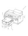
本実施例の記録装置1は、媒体Mをトレイ4の支持面8で支持した状態で移動方向Aに移動する媒体支持ユニット2を備えている。媒体支持ユニット2は、媒体Mの支持部であるトレイ4を有している。記録装置1は、トレイ4に支持された媒体Mを移動方向Aに搬送する媒体搬送部3を備えている。移動方向Aは、方向A1と、方向A1と反対方向の方向A2と、を含む方向である。また、トレイ4はステージ5に載置されている。トレイ4はステージ5と共に、回転レバー9を回転させることにより、高さ方向Cに移動する。なお、媒体Mとしては、テキスタイル(織物、布等)、紙、塩化ビニル樹脂など、種々の素材のものを用いることができる。 The
また、記録装置1の本体内部にはインクを吐出して媒体Mに記録することが可能な記録ヘッド7が備えられている。本実施例において、記録ヘッド7は、媒体Mに記録を実行可能な記録部に相当する。そして、本実施例の記録装置1は、記録ヘッド7が設けられたキャリッジ6を移動方向Aと交差する交差方向Bに往復移動させることで、記録ヘッド7を交差方向Bに往復移動させながら、記録ヘッド7からトレイ4に支持された媒体Mにインクを吐出させて所望の画像を形成する。
なお、本実施例の記録装置1は、図1及び図2中の手前側(左下方向)がトレイ4への媒体Mのセット位置(図2に対応)である。そして、図1及び図2中の奥側(右上方向)の記録開始位置(図1に対応)まで移動方向Aのうちの方向A1に媒体Mをセットしたトレイ4を移動した後、移動方向Aのうちの方向A2にトレイ4を移動しながら記録する。A
In the
なお、本実施例の記録装置1は、交差方向Bに往復移動しながら記録する記録ヘッド7を備えているが、インクを吐出するノズルを移動方向Aと交差する交差方向Bに複数設けた所謂ラインヘッドを備える記録装置でもよい。
ここで、「ラインヘッド」とは、媒体Mの移動方向Aと交差する交差方向Bに形成されたノズルの領域が、媒体Mの交差方向B全体をカバー可能なように設けられ、記録ヘッド又は媒体Mを相対的に移動させて画像を形成する記録装置に用いられる記録ヘッドである。なお、ラインヘッドの交差方向Bのノズルの領域は、記録装置が対応している全ての媒体Mの交差方向B全体をカバー可能でなくてもよい。
また、本実施例の記録ヘッド7は、媒体Mにインクを吐出することで記録可能な記録部であるが、このような記録部に限定されず、例えば、色材を媒体Mに転写して記録する転写式の記録部を使用してもよい。The
Here, the “line head” is provided so that the area of the nozzle formed in the cross direction B intersecting the moving direction A of the medium M can cover the entire cross direction B of the medium M. This is a recording head used in a recording apparatus that forms an image by relatively moving the medium M. Note that the nozzle area in the cross direction B of the line head may not be able to cover the entire cross direction B of all the media M supported by the printing apparatus.
The
また、本実施例の記録装置1は、図3で表されるように、センサーSを備えており、トレイ4に支持される媒体Mと記録ヘッド7との間隔の異常(媒体Mと記録ヘッド7との間隔が狭すぎること)の有無を検出することができる構成になっている。
ここで、センサーSは、発光部Seと受光部Srとを有している。そして、センサーSは、発光部Seから受光部Srに向けて光を照射し、受光部Srで該光を受光したか否かに基づいて、該間隔の異常の有無を検出する構成である。ただし、このような構成に限定はない。Further, as shown in FIG. 3, the
Here, the sensor S includes a light emitting unit Se and a light receiving unit Sr. The sensor S is configured to irradiate light from the light emitting unit Se toward the light receiving unit Sr and detect the presence or absence of an abnormality in the interval based on whether or not the light is received by the light receiving unit Sr. However, such a configuration is not limited.
次に、本発明の実施例1の媒体支持ユニット2について詳細に説明する。
ここで、図4は、本実施例の媒体支持ユニット2を表す概略斜視図である。また、図5は、本実施例の媒体支持ユニット2を表す概略平面図である。また、図6及び図7は、本実施例の媒体支持ユニット2を表す概略側面断面図である。Next, the
Here, FIG. 4 is a schematic perspective view showing the
本実施例の媒体支持ユニット2は、図4で表されるように、支持部としてのトレイ4と、トレイ4に支持される媒体Mを押さえることが可能な押さえ部10と、を備えている。ここで、トレイ4は、媒体Mを支持する支持面8と、支持面8に対して窪んだ受け面12が形成される受け部13と、を有している。また、押さえ部10は、図6で表されるように、受け面12に受けられることで、トレイ4に支持される媒体Mを押さえることが可能な構成である。
そして、受け部13は、支持面8を形成する素材よりも剛性の高い素材で形成されている。このように、本実施例の媒体支持ユニット2は、受け部13を支持面8の形成部材と別部材として構成しているので、受け部13を支持面8と一体的に構成するトレイ4に比べて、受け部13及び支持面8の各々に要求される特性を具備したトレイ4を容易に構成することができている。ここで、受け部13を支持面8と一体的に構成する場合、一般的に損傷しやすい受け部13を損傷しづらくするためには、剛性の高い素材により受け部13及び支持面8を構成するか、受け部13及び支持面8を肉厚に構成する必要がある。しかしながら、剛性の高い素材は重い場合が多く、剛性の高い素材で支持面8を構成すると、トレイ4が重くなる傾向になる。また、受け部13及び支持面8を肉厚に構成すると、当然、トレイ4が重くなる傾向になる。一方、本実施例の媒体支持ユニット2は、一般的に損傷しやすい受け部13を、支持面8の形成部材と別部材として、剛性の高い素材により損傷しづらく構成しているので、トレイ4を薄く軽量に構成することができている。
すなわち、別の表現をすると、本実施例の記録装置1は、薄く軽量に構成されたトレイ4で媒体Mを支持して記録することができる構成になっている。As shown in FIG. 4, the
The receiving
That is, in other words, the
なお、図4及び図5で表されるように、受け部13は、各々が金属製の、受け部13a、13b、13c及び13dの4つで構成されている。このため、受け部13各々を簡単に構成できている。ただし、このような構成に限定されず、受け部13を1つの構成要素で構成してもよい。
また、図5で表されるように、トレイ4の各辺に対応する受け部13a、13b、13c及び13dは、平面視した場合(支持面8と直交する方向から見た場合)に、それぞれの間に隙間がある構成となっている。具体的には、平面視した場合に、受け部13aと受け部13bとの間、受け部13bと受け部13cとの間、受け部13cと受け部13dとの間、及び受け部13dと受け部13aとの間、に隙間がある構成である。別な言い方をすれば、略四角形である支持面8の4つの角に対応する部分には、受け部13が形成されていない構成であるとも言える。このような構成により、トレイ4の体積を減らし、軽量化することができる。
また、支持面8などのトレイ4における受け部13以外の部分はアクリル樹脂で構成されている。ここで、受け部13の素材、並びに、支持面8などのトレイ4における受け部13以外の部分の素材に、限定はない。ただし、強度、重量、コストなどの観点から、受け部13は金属製、支持面8は硬質の高分子物質製であることが好ましい。As shown in FIGS. 4 and 5, the receiving
Further, as shown in FIG. 5, the receiving
Further, portions other than the receiving
また、本実施例のトレイ4は、図4及び図6で表されるように、支持面8と受け面12との間に位置し、支持面8と受け面12とを繋ぐ側面を形成する側面部11を有している。側面部11は、受け部13を形成する素材で形成される第1側面11aを有している。このため、側面部11も損傷しづらく構成することができるので、特にトレイ4を薄く軽量にすることができている。 Further, as shown in FIGS. 4 and 6, the
ここで、受け部13は、受け面12と第1側面11aとが連続して形成されている。このため、側面部11が損傷しづらい構成を簡単に形成できている。すなわち、簡単に、特にトレイ4を薄く軽量にしている。
なお、本実施例の第1側面11aは、受け部13と一体的に構成されているが、受け部13と別部材で構成されていてもよい。Here, as for the receiving
In addition, although the
また、図4及び図6で表されるように、本実施例のトレイ4における側面部11は、支持面8を形成する素材で形成される第2側面11bを有している。詳細には、本実施例のトレイ4は、板状の支持面8の形成部材の端部において、支持面8とは反対側の面17に受け部13の上面16を取り付けている。そして、板状の支持面8の形成部材における支持面8の側面が第2側面11bを形成している。このような構成により、トレイ4の構成を簡単にしている。
また、図6で表されるように、側面部11は、押さえ部10に対し、上側に大きく突出する構成となっている。このような構成により、押さえ部10が外力等によって傾いた場合でも、トレイ4から押さえ部10が外れにくくなる。具体的には、側面部11における高さ方向の辺の50%以上は押さえ部10よりも上側に突出している。このとき、側面部11のうち第1側面11aは、一部は押さえ部10より下方にあり、他の一部は押さえ部10より上方に突出している。また、側面部11のうち第2側面11bは、全体が押さえ部10より上方に突出している。このような構成により、第1側面11aと第2側面11bとの境界部分が押さえ部10と対向しなくなり、1側面11aと第2側面11bとの境界部分に負荷が掛かることを抑制することができる。As shown in FIGS. 4 and 6, the
Further, as shown in FIG. 6, the
また、本実施例の受け部13における受け面12には、ブラスト加工により凹凸が形成されている。このような構成とすることで、トレイ4を薄く軽量にすることができるだけでなく、受け面12は支持面8よりも静止摩擦係数が大きくなっていることで、媒体Mが支持面8で支持され、押さえ部10で押さえられている状態にあるときに、媒体Mが浮いてしまうことを抑制している。
なお、「凹凸」の形成方法に特に限定はない。Further, the receiving
In addition, there is no limitation in particular in the formation method of "unevenness".
また、受け部13における受け面12を、支持面8よりも静止摩擦係数が大きい素材で形成してもよい。このような構成とすることでも、トレイ4を薄く軽量にすることができるだけでなく、媒体Mが支持面8で支持され、押さえ部10で押さえられている状態にあるときに、媒体Mが浮いてしまうことを抑制できる。 Further, the receiving
ここで、図7(A)は、本実施例の媒体支持ユニット2において、図4で表される状態(媒体Mをトレイ4にセットしようとしている状態)から媒体Mを載置したトレイ4に対して押さえ部10を組み合わせた状態であって、この際、方向A2の上流側に浮きWが生じてしまった状態を表している。
また、図7(B)は、図7(A)で表される状態から、作業者が方向A2の下流側の位置(図1及び図2中の手前側(左下方向)の位置)で、媒体Mを方向F1に引っ張り浮き12を解消させたときの状態を表している。
このように、本実施例の媒体支持ユニット2においては、媒体Mが方向F1に引っ張られることに伴い支持面8上の媒体Mが方向F2に移動して浮き12は解消される。これは、受け面12における静止摩擦係数を大きくすることで、方向A2の上流側における受け面12の位置で押さえ部10により確りと押さえられた状態で媒体Mが引っ張られることにより、方向A2の上流側で確りと押さえられつつ支持面8上の媒体Mが方向F2に移動するためである。Here, FIG. 7A shows the
7B is a position on the downstream side in the direction A2 from the state shown in FIG. 7A (the position on the near side (lower left direction) in FIGS. 1 and 2). The state when the medium M is pulled in the direction F1 and the floating 12 is eliminated is shown.
Thus, in the
なお、図4で表されるように、本実施例のトレイ4には、ステージ5から取り外して床などに設置する際の設置部14と、ステージ5に対して位置決め可能な位置決め部15とを備えている。ただし、トレイ4の構成に特に限定はない。 As shown in FIG. 4, the
[実施例2](図8)
次に、本発明の実施例2に係る媒体支持ユニットについて説明する。
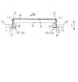
図8は、本発明の実施例2に係る媒体支持ユニット2を表す概略側面断面図であり、実施例1の図6に対応する図である。なお、上記実施例1と共通する構成部材は同じ符号で示しており、詳細な説明は省略する。
本実施例の媒体支持ユニット2は、受け部13の構成のみが実施例1の媒体支持ユニット2と相違する。[Example 2] (FIG. 8)
Next, a medium support unit according to
FIG. 8 is a schematic side sectional view showing the
The
実施例1の媒体支持ユニット2は、側面部11において受け部13が第1側面11aを構成していた。
一方、本実施例の媒体支持ユニット2は、板状の支持面8の形成部材の端部の側面のみが側面部11を形成する構成である。
なお、本実施例の媒体支持ユニット2は、実施例1の記録装置で使用可能である。In the
On the other hand, the
Note that the
[実施例3](図9)
次に、本発明の実施例3に係る媒体支持ユニットについて説明する。
図9は、本発明の実施例3に係る媒体支持ユニット2を表す概略側面断面図であり、実施例1の図6及び実施例2の図8に対応する図である。なお、上記実施例1及び2と共通する構成部材は同じ符号で示しており、詳細な説明は省略する。
本実施例の媒体支持ユニット2は、受け部13のほかに側面部11を構成する側面部構成部材18を備えるという構成のみが実施例1及び2の媒体支持ユニット2と相違する。Example 3 (FIG. 9)
Next, a medium support unit according to
FIG. 9 is a schematic side sectional view showing the
The
実施例1の媒体支持ユニット2は、側面部11において受け部13が第1側面11aを構成していた。また、実施例2の媒体支持ユニット2は、板状の支持面8の形成部材の端部の側面のみが側面部11を形成する構成であった。
一方、本実施例の媒体支持ユニット2は、実施例2の受け部13と同様の構成の受け部13を備え、該受け部13と板状の支持面8の形成部材との間に側面部11を構成する側面部構成部材18を備える構成である。ここで、本実施例の側面部構成部材18は、受け部13と同じ素材で構成されているが、構成部材に特に限定はなく、板状の支持面8の形成部材と同じ素材で構成されていてもよいし、両者と全く別の素材で構成されていてもよい。
なお、本実施例の媒体支持ユニット2は、実施例1の記録装置で使用可能である。In the
On the other hand, the
Note that the
なお、本発明は上記実施例に限定されることなく、特許請求の範囲に記載した発明の範囲内で種々の変形が可能であり、それらも本発明の範囲内に含まれることは言うまでもない。
以上、本発明について具体的な実施例に基づいて詳述した。ここで、本発明について、もう一度まとめて説明する。In addition, this invention is not limited to the said Example, A various deformation | transformation is possible within the range of the invention described in the claim, and it cannot be overemphasized that they are also contained in the scope of the present invention.
The present invention has been described in detail based on the specific embodiments. Here, the present invention will be described once more collectively.
本発明の第1の態様の媒体支持ユニット2は、媒体Mを支持する支持面8と、支持面8に対して窪んだ受け面12が形成される受け部13と、を有する支持部4と、受け面12に受けられることで、支持部4に支持される媒体Mを押さえることが可能な押さえ部10と、を備え、受け部13は、支持面8を形成する素材よりも剛性の高い素材で形成されることを特徴とする。 The
本態様によれば、受け部13は支持面8を形成する素材よりも剛性の高い素材で形成される。このため、受け部13を支持面8の形成部材と別部材として構成することで、受け部13を支持面8と一体的に構成するトレイ4に比べて、受け部13及び支持面8の各々に要求される特性を具備したトレイ4を容易に構成することができる。そして、一般的に損傷しやすい受け部13を、支持面8の形成部材と別部材として、剛性の高い素材により損傷しづらく構成することで、トレイ4を薄く軽量に構成することができる。 According to this aspect, the receiving
本発明の第2の態様の媒体支持ユニット2は、前記第1の態様において、支持部4は、支持面8と受け面12との間に位置し、支持面8と受け面12とを繋ぐ側面を形成する側面部11を有し、側面部11は、受け部12を形成する素材で形成される第1側面11aを有することを特徴とする。 In the
本態様によれば、側面部11は受け部13を形成する素材で形成される第1側面11aを有する。このため、側面部11も損傷しづらく構成することができるので、特に支持部4を薄く軽量にすることができる。 According to this aspect, the
本発明の第3の態様の媒体支持ユニット2は、前記第2の態様において、側面部11は、支持面8を形成する素材で形成される第2側面11bを有することを特徴とする。 The
本態様によれば、側面部11は支持面8を形成する素材で形成される第2側面11bを有する。このため、例えば、板状の支持面8の形成部材の端部において、支持面8とは反対側の面17に受け部を取り付けるなど、支持部4の構成を簡単にすることができる。 According to this aspect, the
本発明の第4の態様の媒体支持ユニット2は、前記第2又は第3の態様において、受け部13は、受け面12と第1側面11aとが連続して形成されることを特徴とする。 The
本態様によれば、受け部13は受け面12と第1側面11aとが連続して形成される。このため、側面部11が損傷しづらい構成を簡単に形成できるので、簡単に、特に支持部4を薄く軽量にすることができる。 According to this aspect, the receiving
本発明の第5の態様の媒体支持ユニット2は、前記第1から第4のいずれか1つの態様において、受け面12は、支持面8よりも静止摩擦係数が大きい素材で形成されることを特徴とする。 In the
本態様によれば、受け面12は支持面8よりも静止摩擦係数が大きい素材で形成される。このような構成とすることで、支持部4を薄く軽量にすることができるだけでなく、媒体Mが支持面8で支持され押さえ部で押さえられている状態にあるときに媒体Mが浮いてしまうことを抑制できる。 According to this aspect, the receiving
本発明の第6の態様の媒体支持ユニット2は、前記第1から第5のいずれか1つの態様において、受け面12には、凹凸が形成されていることを特徴とする。 The
本態様によれば、受け面12には凹凸が形成されている。このような構成とすることで、支持部4を薄く軽量にすることができるだけでなく、媒体Mが支持面8で支持され押さえ部10で押さえられている状態にあるときに媒体Mが浮いてしまうことを抑制できる。
なお、「凹凸」の形成方法に特に限定はないが、例えば、ブラスト加工をすることなどにより、押さえ部10における媒体Mとの接触面11a及び11bに凹凸を形成することができる。According to this aspect, the receiving
The method for forming the “unevenness” is not particularly limited. For example, the unevenness can be formed on the contact surfaces 11 a and 11 b of the
本発明の第7の態様の記録装置1は、前記第1から第6のいずれか1つの態様の媒体支持ユニット2と、媒体支持ユニット2に支持された媒体Mに記録可能な記録部7と、を備えることを特徴とする。 A
本態様によれば、薄く軽量な支持部4で媒体Mを支持して記録することができる。 According to this aspect, the medium M can be supported and recorded by the thin and
1 記録装置、2 媒体支持ユニット、3 媒体搬送部、4 トレイ(支持部)、
5 ステージ、6 キャリッジ、7 記録ヘッド(記録部)、8 支持面、
9 回転レバー、10 押さえ部、11 側面部、11a 第1側面、
11b 第2側面、12 受け面、13 受け部、13a 受け部、13b 受け部、
13c 受け部、13d 受け部、14 設置部、15 位置決め部、
16 受け部13の上面、17 トレイの支持面8とは反対側の面、
18 側面部構成部材、M 媒体、S センサー、Se 発光部、Sr 受光部、
W 媒体Mの浮き1 recording device, 2 medium support unit, 3 medium transport section, 4 tray (support section),
5 stage, 6 carriage, 7 recording head (recording unit), 8 support surface,
9 rotating lever, 10 holding part, 11 side part, 11a first side face,
11b 2nd side surface, 12 receiving surface, 13 receiving part, 13a receiving part, 13b receiving part,
13c receiving part, 13d receiving part, 14 installation part, 15 positioning part,
16 upper surface of the receiving
18 side surface component, M medium, S sensor, Se light emitting unit, Sr light receiving unit,
W Floating medium M
Claims (5)
Translated fromJapanese前記受け面に受けられることで、前記支持部に支持される前記媒体を押さえることが可能な押さえ部と、を備え、
前記受け部は、前記支持面を形成する素材よりも剛性の高い素材で形成され、
前記支持部は、前記支持面と前記受け面との間に位置し、前記支持面と前記受け面とを繋ぐ側面を形成する側面部を有し、
前記側面部は、前記受け部を形成する素材で形成される第1側面と、前記支持面を形成する素材で形成される第2側面と、を有することを特徴とする媒体支持ユニット。A support portion having a support surface that supports the medium, and a receiving portion in which a receiving surface that is recessed with respect to the support surface is formed;
A pressing part capable of pressing the medium supported by the support part by being received by the receiving surface;
The receiving portion is formed of a material having higher rigidity than a material forming the support surface,
The support portion is located between the support surface and the receiving surface, and has a side surface portion that forms a side surface connecting the support surface and the receiving surface.
Said side portions, said a first side surface that is receiving unit is formed from a material that forms the said medium supporting unit tothe second aspect, wherein Rukototo have a formed of a material which forms a support surface.
前記受け部は、前記受け面と前記第1側面とが連続して形成されることを特徴とする媒体支持ユニット。The medium support unit according to claim1 , wherein
The medium supporting unit according to claim 1, wherein the receiving portion is formed such that the receiving surface and the first side surface are continuously formed.
前記受け面は、前記支持面よりも静止摩擦係数が大きい素材で形成されることを特徴とする媒体支持ユニット。The medium support unit according to claim 1or 2 ,
The medium support unit, wherein the receiving surface is made of a material having a static friction coefficient larger than that of the support surface.
前記受け面には、凹凸が形成されていることを特徴とする媒体支持ユニット。The medium support unit according to any one of claims 1 to3 ,
An unevenness is formed on the receiving surface, and the medium support unit.
前記媒体支持ユニットに支持された前記媒体に記録可能な記録部と、
を備えることを特徴とする記録装置。The medium support unit according to any one of claims 1 to4 ,
A recording unit capable of recording on the medium supported by the medium support unit;
A recording apparatus comprising:
Priority Applications (3)
| Application Number | Priority Date | Filing Date | Title |
|---|---|---|---|
| JP2015035015AJP6460327B2 (en) | 2015-02-25 | 2015-02-25 | Medium support unit and recording apparatus |
| US15/051,469US9694600B2 (en) | 2015-02-25 | 2016-02-23 | Medium supporting unit and recording apparatus |
| US15/611,944US9889678B2 (en) | 2015-02-25 | 2017-06-02 | Medium supporting unit and recording apparatus |
Applications Claiming Priority (1)
| Application Number | Priority Date | Filing Date | Title |
|---|---|---|---|
| JP2015035015AJP6460327B2 (en) | 2015-02-25 | 2015-02-25 | Medium support unit and recording apparatus |
Publications (2)
| Publication Number | Publication Date |
|---|---|
| JP2016155313A JP2016155313A (en) | 2016-09-01 |
| JP6460327B2true JP6460327B2 (en) | 2019-01-30 |
Family
ID=56693560
Family Applications (1)
| Application Number | Title | Priority Date | Filing Date |
|---|---|---|---|
| JP2015035015AActiveJP6460327B2 (en) | 2015-02-25 | 2015-02-25 | Medium support unit and recording apparatus |
Country Status (2)
| Country | Link |
|---|---|
| US (2) | US9694600B2 (en) |
| JP (1) | JP6460327B2 (en) |
Families Citing this family (7)
| Publication number | Priority date | Publication date | Assignee | Title |
|---|---|---|---|---|
| JP6460327B2 (en) | 2015-02-25 | 2019-01-30 | セイコーエプソン株式会社 | Medium support unit and recording apparatus |
| JP6799277B2 (en)* | 2017-02-24 | 2020-12-16 | セイコーエプソン株式会社 | How to attach the medium support unit, printing device and friction member |
| JP6885225B2 (en)* | 2017-05-01 | 2021-06-09 | 株式会社リコー | Cloth holding member, printing device, image imparting device, holding member of printed member, heating device |
| EP3399837B8 (en)* | 2017-05-01 | 2019-12-25 | Ricoh Company, Ltd. | Liquid discharge apparatus |
| JP2019075319A (en)* | 2017-10-18 | 2019-05-16 | 株式会社リコー | Heating device, image applying device, and image applying method |
| JP7302361B2 (en)* | 2019-07-31 | 2023-07-04 | 株式会社リコー | Holding device, printing device, fixing device and printing system |
| JP2025006109A (en)* | 2023-06-29 | 2025-01-17 | ブラザー工業株式会社 | Auxiliary member |
Family Cites Families (11)
| Publication number | Priority date | Publication date | Assignee | Title |
|---|---|---|---|---|
| JP2850266B2 (en) | 1990-06-26 | 1999-01-27 | 三菱電機ホーム機器株式会社 | microwave |
| JP3969168B2 (en) | 2002-04-23 | 2007-09-05 | ブラザー工業株式会社 | Platen device for inkjet printer |
| US7040748B2 (en)* | 2003-03-13 | 2006-05-09 | Brother Kogyo Kabushiki Kaisha | Inkjet printing apparatus |
| JP4055622B2 (en)* | 2003-03-27 | 2008-03-05 | ブラザー工業株式会社 | Fabric printing apparatus and platen used therefor |
| JP5825474B2 (en)* | 2011-07-22 | 2015-12-02 | セイコーエプソン株式会社 | Inkjet printing device |
| JP5807447B2 (en)* | 2011-08-26 | 2015-11-10 | セイコーエプソン株式会社 | Inkjet printing device |
| JP5928684B2 (en)* | 2011-09-26 | 2016-06-01 | セイコーエプソン株式会社 | Pretreatment method for printing material, pretreatment apparatus, inkjet printing apparatus, and inkjet printing method |
| JP5974359B2 (en) | 2012-04-24 | 2016-08-23 | セイコーエプソン株式会社 | SET TRAY, INKJET PRINTING APPARATUS AND PRINTED PRODUCTION METHOD |
| JP5982988B2 (en)* | 2012-04-24 | 2016-08-31 | セイコーエプソン株式会社 | SET TRAY, INKJET PRINTING APPARATUS, SET TRAY STORAGE METHOD AND PRINTED PRODUCTION METHOD |
| US9272538B2 (en)* | 2012-10-05 | 2016-03-01 | Darren Livingston | Digital printer platen material holding apparatus |
| JP6460327B2 (en) | 2015-02-25 | 2019-01-30 | セイコーエプソン株式会社 | Medium support unit and recording apparatus |
- 2015
- 2015-02-25JPJP2015035015Apatent/JP6460327B2/enactiveActive
- 2016
- 2016-02-23USUS15/051,469patent/US9694600B2/enactiveActive
- 2017
- 2017-06-02USUS15/611,944patent/US9889678B2/enactiveActive
Also Published As
| Publication number | Publication date |
|---|---|
| US9889678B2 (en) | 2018-02-13 |
| US20160243852A1 (en) | 2016-08-25 |
| US20170266984A1 (en) | 2017-09-21 |
| US9694600B2 (en) | 2017-07-04 |
| JP2016155313A (en) | 2016-09-01 |
Similar Documents
| Publication | Publication Date | Title |
|---|---|---|
| JP6460327B2 (en) | Medium support unit and recording apparatus | |
| JP6088398B2 (en) | Marking station maintenance device and method for cleaning marking station | |
| US9073369B2 (en) | Recording apparatus and method of manufacturing recorded matter | |
| US20110292145A1 (en) | Media hold-down system having cross process chambering | |
| JP2010094976A5 (en) | ||
| JP6429076B2 (en) | Medium support unit, recording apparatus, and medium support method | |
| JP6199790B2 (en) | Conveying apparatus and inkjet recording apparatus | |
| JP2011025498A (en) | Inkjet recorder and method of conveying recording medium in inkjet recorder | |
| JP2009285897A (en) | Recording apparatus | |
| CN105269960A (en) | Ink-jet recording apparatus | |
| JP6232965B2 (en) | Recording device | |
| JP2014140989A (en) | Recording device | |
| JP6198639B2 (en) | Printing apparatus and sheet support apparatus | |
| JP4873084B2 (en) | Inkjet recording device | |
| JP2016155272A (en) | Medium support unit, recording device, and medium support method | |
| CN106256559B (en) | Cleaning method of liquid ejection device and scale unit | |
| US9701134B2 (en) | Medium supporting unit and recording apparatus | |
| JP6373178B2 (en) | Inkjet recording device | |
| US9446607B2 (en) | Spacer with integral flange for print head protection | |
| JP6365815B2 (en) | Recording device | |
| JP5136753B2 (en) | Recording material support device, recording device | |
| JP2016175376A (en) | Recording apparatus and projection method | |
| JP2015185670A (en) | Support device and support method of planar member | |
| US20140015910A1 (en) | Printer and paper transport method in printer | |
| JP2017119414A (en) | Apparatus for ejecting liquid, method and program for ejecting liquid |
Legal Events
| Date | Code | Title | Description |
|---|---|---|---|
| A621 | Written request for application examination | Free format text:JAPANESE INTERMEDIATE CODE: A621 Effective date:20171219 | |
| A977 | Report on retrieval | Free format text:JAPANESE INTERMEDIATE CODE: A971007 Effective date:20180920 | |
| A131 | Notification of reasons for refusal | Free format text:JAPANESE INTERMEDIATE CODE: A131 Effective date:20180925 | |
| A521 | Written amendment | Free format text:JAPANESE INTERMEDIATE CODE: A523 Effective date:20181030 | |
| TRDD | Decision of grant or rejection written | ||
| A01 | Written decision to grant a patent or to grant a registration (utility model) | Free format text:JAPANESE INTERMEDIATE CODE: A01 Effective date:20181205 | |
| A61 | First payment of annual fees (during grant procedure) | Free format text:JAPANESE INTERMEDIATE CODE: A61 Effective date:20181218 | |
| R150 | Certificate of patent or registration of utility model | Ref document number:6460327 Country of ref document:JP Free format text:JAPANESE INTERMEDIATE CODE: R150 |