JP6460080B2 - In-vehicle network system - Google Patents
In-vehicle network systemDownload PDFInfo
- Publication number
- JP6460080B2 JP6460080B2JP2016217552AJP2016217552AJP6460080B2JP 6460080 B2JP6460080 B2JP 6460080B2JP 2016217552 AJP2016217552 AJP 2016217552AJP 2016217552 AJP2016217552 AJP 2016217552AJP 6460080 B2JP6460080 B2JP 6460080B2
- Authority
- JP
- Japan
- Prior art keywords
- master
- devices
- relay
- priority
- requesting
- Prior art date
- Legal status (The legal status is an assumption and is not a legal conclusion. Google has not performed a legal analysis and makes no representation as to the accuracy of the status listed.)
- Active
Links
Images


Classifications
- H—ELECTRICITY
- H04—ELECTRIC COMMUNICATION TECHNIQUE
- H04L—TRANSMISSION OF DIGITAL INFORMATION, e.g. TELEGRAPHIC COMMUNICATION
- H04L12/00—Data switching networks
- H04L12/28—Data switching networks characterised by path configuration, e.g. LAN [Local Area Networks] or WAN [Wide Area Networks]
- H04L12/40—Bus networks
- H04L12/40143—Bus networks involving priority mechanisms
- H04L12/40163—Bus networks involving priority mechanisms by assigning priority to messages according to a message field
- G—PHYSICS
- G07—CHECKING-DEVICES
- G07C—TIME OR ATTENDANCE REGISTERS; REGISTERING OR INDICATING THE WORKING OF MACHINES; GENERATING RANDOM NUMBERS; VOTING OR LOTTERY APPARATUS; ARRANGEMENTS, SYSTEMS OR APPARATUS FOR CHECKING NOT PROVIDED FOR ELSEWHERE
- G07C5/00—Registering or indicating the working of vehicles
- G07C5/008—Registering or indicating the working of vehicles communicating information to a remotely located station
- G—PHYSICS
- G07—CHECKING-DEVICES
- G07C—TIME OR ATTENDANCE REGISTERS; REGISTERING OR INDICATING THE WORKING OF MACHINES; GENERATING RANDOM NUMBERS; VOTING OR LOTTERY APPARATUS; ARRANGEMENTS, SYSTEMS OR APPARATUS FOR CHECKING NOT PROVIDED FOR ELSEWHERE
- G07C5/00—Registering or indicating the working of vehicles
- G07C5/08—Registering or indicating performance data other than driving, working, idle, or waiting time, with or without registering driving, working, idle or waiting time
- G07C5/0808—Diagnosing performance data
- H—ELECTRICITY
- H04—ELECTRIC COMMUNICATION TECHNIQUE
- H04L—TRANSMISSION OF DIGITAL INFORMATION, e.g. TELEGRAPHIC COMMUNICATION
- H04L12/00—Data switching networks
- H04L12/28—Data switching networks characterised by path configuration, e.g. LAN [Local Area Networks] or WAN [Wide Area Networks]
- H04L12/40—Bus networks
- H04L12/40006—Architecture of a communication node
- H04L12/40019—Details regarding a bus master
- H—ELECTRICITY
- H04—ELECTRIC COMMUNICATION TECHNIQUE
- H04L—TRANSMISSION OF DIGITAL INFORMATION, e.g. TELEGRAPHIC COMMUNICATION
- H04L41/00—Arrangements for maintenance, administration or management of data switching networks, e.g. of packet switching networks
- H04L41/06—Management of faults, events, alarms or notifications
- G—PHYSICS
- G07—CHECKING-DEVICES
- G07C—TIME OR ATTENDANCE REGISTERS; REGISTERING OR INDICATING THE WORKING OF MACHINES; GENERATING RANDOM NUMBERS; VOTING OR LOTTERY APPARATUS; ARRANGEMENTS, SYSTEMS OR APPARATUS FOR CHECKING NOT PROVIDED FOR ELSEWHERE
- G07C2205/00—Indexing scheme relating to group G07C5/00
- G07C2205/02—Indexing scheme relating to group G07C5/00 using a vehicle scan tool
- H—ELECTRICITY
- H04—ELECTRIC COMMUNICATION TECHNIQUE
- H04L—TRANSMISSION OF DIGITAL INFORMATION, e.g. TELEGRAPHIC COMMUNICATION
- H04L67/00—Network arrangements or protocols for supporting network services or applications
- H04L67/01—Protocols
- H04L67/12—Protocols specially adapted for proprietary or special-purpose networking environments, e.g. medical networks, sensor networks, networks in vehicles or remote metering networks
Landscapes
- Engineering & Computer Science (AREA)
- Computer Networks & Wireless Communication (AREA)
- Signal Processing (AREA)
- Physics & Mathematics (AREA)
- General Physics & Mathematics (AREA)
- Small-Scale Networks (AREA)
- Health & Medical Sciences (AREA)
- Computing Systems (AREA)
- General Health & Medical Sciences (AREA)
- Medical Informatics (AREA)
Description
Translated fromJapanese本発明は、車載ネットワークシステムに関する。 The present invention relates to an in-vehicle network system.
複数の機器から制御装置(ECU)への同様の応答要求に対して、何れか1つの特定の機器からの応答要求に対する応答を優先的に行う等の調停を行う車載ネットワーク技術が知られている(例えば、特許文献1)。 In-vehicle network technology is known that performs arbitration such as preferentially responding to a response request from any one specific device in response to a similar response request from a plurality of devices to a control unit (ECU). (For example, patent document 1).
特許文献1では、各種ECUが属するCANプロトコルに基づく複数のローカルネットワーク(LAN)と、一時的に接続可能なダイアグ用ツールと、サーバからの応答要求を受信可能なDCM(通信機器)とが1つの中継装置に接続される。そして、該中継装置は、ダイアグ用ツールからの応答要求を受信すると、DCM(サーバ)からの応答要求に対する処理を中止する調停を行うことが開示されている。 In Patent Document 1, a plurality of local networks (LAN) based on a CAN protocol to which various ECUs belong, a diagnostic tool that can be temporarily connected, and a DCM (communication device) that can receive a response request from a server are 1 Connected to one relay device. It is disclosed that when the relay device receives a response request from the diagnostic tool, the relay device performs arbitration to stop processing for the response request from the DCM (server).
しかしながら、イーサネット(登録商標)プロトコルに基づく車載ネットワークでは、各機器が1対1で接続する接続形態が採用される。そのため、例えば、各種ECUが属する複数のローカルネットワーク同士を接続させるためには、各ローカルネットワークに対応する中継装置を設け、各中継装置同士を1対1で接続することにより、異なるローカルネットワーク間の通信を行う必要がある。また、車両では、右ハンドル車、左ハンドル車等のように、車載ネットワークの物理的な配置仕様が多く存在する場合があり、ECUに対する応答要求を行う機器の接続先になる中継装置も、各仕様に依って、異なる可能性がある。従って、特許文献1のように、複数の中継装置の中から予め決められた1つの中継装置に調停を行わせる方法を採用することができない可能性がある。 However, in an in-vehicle network based on the Ethernet (registered trademark) protocol, a connection form in which each device is connected in a one-to-one manner is employed. Therefore, for example, in order to connect a plurality of local networks to which various ECUs belong, a relay device corresponding to each local network is provided, and each relay device is connected in a one-to-one relationship between different local networks. It is necessary to communicate. Moreover, in vehicles, there are cases where there are many physical arrangement specifications of in-vehicle networks, such as right-hand drive cars, left-hand drive cars, etc. Depending on the specification, it may vary. Therefore, there is a possibility that a method of arbitrating one relay device determined in advance from among a plurality of relay devices as in Patent Document 1 may not be adopted.
そこで、上記課題に鑑み、イーサネットプロトコルに基づく車載ネットワークにおいて、各種制御装置(ECU)に対する応答要求を行う複数の機器のうちの何れか1つからの応答要求に関する処理を優先的に行う等の調停を適切に行うことが可能な車載ネットワークシステムを提供することを目的とする。 Therefore, in view of the above problems, in an in-vehicle network based on the Ethernet protocol, arbitration such as preferentially performing processing related to a response request from any one of a plurality of devices that make response requests to various control units (ECUs). An object of the present invention is to provide an in-vehicle network system capable of appropriately performing the above.
上記目的を達成するため、本発明の一実施形態では、
車両に搭載される車載ネットワークシステムであって、
少なくとも1つに前記車両の制御装置が接続され、相互に通信可能な複数の中継装置であって、前記制御装置に対して応答要求を送信する複数の要求装置の各々を何れか予め規定された1つに接続可能な複数の中継装置と、
前記複数の要求装置の各々から送信される前記応答要求の優先度を表す優先度情報を記憶する記憶部と、
前記複数の中継装置の中から1つをマスタに設定するマスタ設定部であって、前記複数の要求装置の何れか1つが、予め規定されたタイミング以降で接続されたことがある前記中継装置のうちの前記優先度が最も高い前記要求装置が接続されたことがある前記中継装置、又は、前記複数の要求装置の何れか1つが接続されている前記中継装置のうちの前記優先度が最も高い前記要求装置が接続されている前記中継装置を前記マスタに設定するマスタ設定部と、
前記複数の中継装置の各々に含まれる調停部であって、自己が含まれる前記中継装置が、前記マスタに設定されている場合、前記複数の要求装置のうちの少なくとも2つから前記応答要求が送信されたときに、前記優先度が最も高い前記要求装置からの前記応答要求が優先的に前記制御装置に送信されるように調停を行う調停部と、を含む、
車載ネットワークシステムが提供される。In order to achieve the above object, in one embodiment of the present invention,
An in-vehicle network system mounted on a vehicle,
A plurality of relay devices that are connected to at least one of the vehicle control devices and can communicate with each other, and each of the plurality of request devices that transmit a response request to the control device is defined in advance. A plurality of relay devices connectable to one;
A storage unit for storing priority information indicating the priority of the response request transmitted from each of the plurality of requesting devices;
A master setting unit that sets one of the plurality of relay devices as a master, wherein any one of the plurality of request devices is connected after a predetermined timing. Of the relay devices to which the requesting device having the highest priority is connected, or the relay device to which any one of the plurality of requesting devices is connected has the highest priority. A master setting unit that sets the relay device to which the requesting device is connected as the master;
In the arbitration unit included in each of the plurality of relay devices, when the relay device including itself is set as the master, the response request is received from at least two of the plurality of request devices. An arbitration unit that, when transmitted, performs arbitration so that the response request from the requesting device having the highest priority is transmitted to the control device preferentially;
An in-vehicle network system is provided.
本実施形態によれば、イーサネットプロトコルに基づく車載ネットワークのように、複数の要求装置が接続されうる中継装置が複数ある場合であっても、複数の中継装置の中から自動的にマスタとなる中継装置を設定することができる。また、車両の各種仕様(例えば、右ハンドル車、左ハンドル車等の別)に依って、複数の中継装置のレイアウト等が異なり、どの中継装置にどの要求装置が接続するかが変更される場合であっても、事後的に、即ち、車両完成後に、複数の要求装置の中から自動的にマスタとなる要求装置を設定することができる。そのため、マスタとして設定された中継装置は、複数の要求装置からの応答信号に関する調停処理を適切に行うことができる。 According to the present embodiment, even when there are a plurality of relay devices to which a plurality of request devices can be connected, such as an in-vehicle network based on the Ethernet protocol, a relay that automatically becomes a master from the plurality of relay devices. The device can be set up. Also, depending on the vehicle specifications (for example, right-hand drive car, left-hand drive car, etc.), the layout of multiple relay devices is different, and which request device is connected to which relay device is changed Even so, after the completion of the vehicle, that is, after completion of the vehicle, it is possible to automatically set a request device as a master from a plurality of request devices. Therefore, the relay device set as the master can appropriately perform the arbitration process regarding the response signals from the plurality of requesting devices.
また、上述の実施形態において、
前記記憶部及び前記マスタ設定部は、各前記複数の中継装置に含まれると共に、
各前記複数の中継装置は、
自己が含まれる前記中継装置の前記マスタ設定部により前記マスタが設定された場合、前記マスタとして設定された前記中継装置を示すマスタ情報を、自己が含まれる前記中継装置以外の前記複数の中継装置に送信する第1送信部と、
自己が含まれる前記中継装置以外の前記複数の中継装置から送信される前記マスタ情報を受信する第1受信部と、
自己が含まれる前記中継装置に前記複数の要求装置の何れか1つが接続された場合、接続された前記要求装置に関する接続情報を、自己が含まれる前記中継装置以外の前記複数の中継装置に送信する第2送信部と、
自己が含まれる前記中継装置以外の前記複数の中継装置から送信される前記接続情報を受信する第2受信部と、を更に含み、
各前記マスタ設定部は、前記マスタが設定されていない場合、前記複数の要求装置の何れか1つが、自己が含まれる前記中継装置に接続されたときに、当該中継装置をマスタとして設定し、自己が含まれる前記中継装置が前記マスタに設定されている場合、前記マスタに設定されていない前記中継装置に、前記複数の要求装置の何れか1つが接続されたときに、前記複数の要求装置の何れか1つが、予め規定されたタイミング以降で接続されたことがある前記中継装置のうちの前記優先度が最も高い前記要求装置が接続されたことがある前記中継装置、又は、前記複数の要求装置の何れかが現に接続されている前記中継装置のうちの前記優先度が最も高い前記要求装置が接続されている前記中継装置を前記マスタに設定してもよい。In the above embodiment,
The storage unit and the master setting unit are included in each of the plurality of relay devices,
Each of the plurality of relay devices is
When the master is set by the master setting unit of the relay device including the master, the plurality of relay devices other than the relay device including the master information indicating the relay device set as the master A first transmitter for transmitting to
A first receiving unit that receives the master information transmitted from the plurality of relay devices other than the relay device including itself;
When any one of the plurality of requesting devices is connected to the relay device including itself, connection information regarding the connected requesting device is transmitted to the plurality of relay devices other than the relay device including the self A second transmitter to
A second receiving unit that receives the connection information transmitted from the plurality of relay devices other than the relay device including itself; and
Each of the master setting units, when the master is not set, when any one of the plurality of requesting devices is connected to the relay device including itself, sets the relay device as a master, When the relay device including the self is set as the master, when any one of the plurality of request devices is connected to the relay device not set as the master, the plurality of request devices Any one of the relay devices that have been connected after a predetermined timing, the relay device that has been connected to the requesting device having the highest priority, or the plurality of relay devices The relay device to which the requesting device having the highest priority among the relay devices to which any requesting device is currently connected may be set as the master.
本実施形態によれば、複数の中継装置に含まれる各マスタ設定部のうちの所定の条件を満足する1つのマスタ設定部(具体的には、マスタが設定されていない場合に、何れか1つの要求装置が接続された中継装置に含まれるマスタ設定部、及びマスタが設定されている場合に、マスタとして設定されている中継装置に含まれるマスタ設定部)がマスタの設定を行うことができると共に、マスタに設定された中継装置に関するマスタ情報を、複数の中継装置で共有することができる。 According to the present embodiment, one master setting unit that satisfies a predetermined condition among the master setting units included in a plurality of relay devices (specifically, any one is set when no master is set). The master setting unit included in the relay device to which one requesting device is connected, and the master setting unit included in the relay device set as the master when the master is set can set the master At the same time, the master information related to the relay device set as the master can be shared by a plurality of relay devices.
また、上述の実施形態において、
前記記憶部及び前記マスタ設定部は、前記複数の中継装置のうちの何れか1つの中継装置に含まれると共に、
前記何れか1つの中継装置は、
前記何れか1つの中継装置以外の前記複数の中継装置から、接続された前記要求装置に関する接続情報を受信する第3受信部と、
前記マスタ設定部により前記マスタが設定された場合、前記何れか1つの中継装置以外の前記複数の中継装置に対して、前記マスタに設定された前記中継装置に関するマスタ情報を送信する第3送信部と、を更に含み、
前記何れか1つの中継装置以外の前記複数の中継装置の各々は、
自己が含まれる前記中継装置に前記複数の要求装置の何れか1つが接続された場合、前記何れか1つの中継装置に対して、接続された前記要求装置に関する前記接続情報を送信する第4送信部と、
前記何れか1つの中継装置から送信される前記マスタ情報を受信する第4受信部と、を更に含み、
前記マスタ設定部は、前記マスタが設定されていない場合、前記複数の要求装置の何れか1つが前記複数の中継装置の何れか1つに接続されたときに、前記要求装置が接続された前記中継装置をマスタとして設定し、前記マスタが設定されている場合、前記マスタに設定されていない前記中継装置に、前記複数の要求装置の何れか1つが接続されたときに、前記複数の要求装置の何れか1つが、予め規定されたタイミング以降で接続されたことがある前記中継装置のうちの前記優先度が最も高い前記要求装置が接続されたことがある前記中継装置、又は、前記複数の要求装置の何れか1つが接続されている前記中継装置のうちの前記優先度が最も高い前記要求装置が接続されている前記中継装置を前記マスタに設定してもよい。In the above embodiment,
The storage unit and the master setting unit are included in any one of the plurality of relay devices,
Any one of the relay devices is
A third receiving unit for receiving connection information regarding the connected requesting device from the plurality of relaying devices other than any one of the relaying devices;
When the master is set by the master setting unit, a third transmission unit that transmits master information related to the relay device set as the master to the plurality of relay devices other than any one of the relay devices And further including
Each of the plurality of relay devices other than any one of the relay devices is
When any one of the plurality of request devices is connected to the relay device including itself, a fourth transmission that transmits the connection information regarding the connected request device to any one of the relay devices. And
A fourth receiver for receiving the master information transmitted from any one of the relay devices,
When the master is not set, the master setting unit is connected to the requesting device when any one of the plurality of requesting devices is connected to any one of the plurality of relay devices. When a relay apparatus is set as a master and the master is set, when any one of the plurality of request apparatuses is connected to the relay apparatus that is not set as the master, the plurality of request apparatuses Any one of the relay devices that have been connected after a predetermined timing, the relay device that has been connected to the requesting device having the highest priority, or the plurality of relay devices The relay device to which the request device having the highest priority among the relay devices to which any one of the request devices is connected may be set as the master.
本実施形態によれば、複数の中継装置のうちの何れか1つの中継装置に含まれるマスタ設定部によって、マスタの設定を行うことができると共に、マスタに設定された中継装置に関するマスタ情報を、複数の中継装置で共有することができる。 According to the present embodiment, the master setting unit included in any one of the plurality of relay devices can set the master, and master information related to the relay device set as the master, It can be shared by multiple relay devices.
また、上述の実施形態において、
前記記憶部及び前記マスタ設定部は、前記車両に搭載される、前記複数の中継装置と相互に通信可能な外部装置に設けられ、
前記外部装置は、
前記複数の中継装置の各々から、接続された前記要求装置に関する接続情報を受信する第5受信部と、
前記マスタ設定部により前記マスタが設定された場合、前記複数の中継装置の各々に対して、前記マスタに設定された前記中継装置に関するマスタ情報を送信する第5送信部と、を更に含み、
各前記複数の中継装置は、
自己が含まれる前記中継装置に前記複数の要求装置の何れか1つが接続された場合、前記外部装置に対して、接続された前記要求装置に関する前記接続情報を送信する第6送信部と、
前記外部装置から送信される前記マスタ情報を受信する第6受信部と、を更に含み、
前記マスタ設定部は、前記マスタが設定されていない場合、前記複数の要求装置の何れか1つが前記複数の中継装置の何れか1つに接続されたときに、前記要求装置が接続された前記中継装置をマスタとして設定し、前記マスタが設定されている場合、前記マスタに設定されていない前記中継装置に、前記複数の要求装置の何れか1つが接続されたときに、前記複数の要求装置の何れか1つが、予め規定されたタイミング以降で接続されたことがある前記中継装置のうちの前記優先度が最も高い前記要求装置が接続されたことがある前記中継装置、又は、前記複数の要求装置の何れか1つが接続されている前記中継装置のうちの前記優先度が最も高い前記要求装置が接続されている前記中継装置を前記マスタに設定してもよい。In the above embodiment,
The storage unit and the master setting unit are provided in an external device mounted on the vehicle and capable of mutual communication with the plurality of relay devices,
The external device is
A fifth receiving unit for receiving connection information regarding the connected requesting device from each of the plurality of relay devices;
When the master is set by the master setting unit, a fifth transmission unit that transmits master information related to the relay device set as the master to each of the plurality of relay devices, and
Each of the plurality of relay devices is
When any one of the plurality of requesting devices is connected to the relay device including itself, a sixth transmission unit that transmits the connection information regarding the connected requesting device to the external device;
A sixth receiving unit that receives the master information transmitted from the external device;
When the master is not set, the master setting unit is connected to the requesting device when any one of the plurality of requesting devices is connected to any one of the plurality of relay devices. When a relay apparatus is set as a master and the master is set, when any one of the plurality of request apparatuses is connected to the relay apparatus that is not set as the master, the plurality of request apparatuses Any one of the relay devices that have been connected after a predetermined timing, the relay device that has been connected to the requesting device having the highest priority, or the plurality of relay devices The relay device to which the request device having the highest priority among the relay devices to which any one of the request devices is connected may be set as the master.
本実施形態によれば、複数の中継装置と相互に通信可能な外部装置に含まれるマスタ設定部によって、マスタの設定を行うことができると共に、マスタに設定された中継装置に関するマスタ情報を、複数の中継装置で共有することができる。 According to the present embodiment, a master setting unit included in an external device capable of mutual communication with a plurality of relay devices can set the master, and a plurality of pieces of master information regarding the relay device set as the master can be obtained. Can be shared by other relay devices.
また、上述の実施形態において、
前記調停部は、自己が含まれる前記中継装置が前記マスタとして設定されている場合、当該中継装置に接続される前記要求装置から応答要求が送信されるときに、当該要求装置以外の前記複数の要求装置との通信の遮断を指令する指令信号を、マスタとして設定されていない前記中継装置に送信してもよい。In the above embodiment,
When the relay device including the relay device is set as the master, the arbitration unit, when a response request is transmitted from the request device connected to the relay device, the plurality of devices other than the request device. A command signal for commanding interruption of communication with the requesting device may be transmitted to the relay device that is not set as a master.
本実施形態によれば、マスタとして設定されている中継装置、即ち、最も優先度が高い要求装置が接続されている中継装置に含まれる調停部は、当該要求装置からの応答要求が送信されると、マスタとして設定されていない(即ち、スレーブである)中継装置に対して、他の要求装置との通信を遮断させることができる。そのため、調停部は、最も優先度が高い要求装置からの応答要求を優先的に制御装置に送信(転送)することができる。 According to the present embodiment, the arbitration unit included in the relay device set as the master, that is, the relay device to which the request device having the highest priority is connected transmits the response request from the request device. Then, it is possible to block communication with other requesting devices for a relay device that is not set as a master (that is, is a slave). Therefore, the arbitration unit can preferentially transmit (transfer) a response request from the requesting device having the highest priority to the control device.
また、上述の実施形態において、
前記複数の要求装置は、前記複数の中継装置の何れか1つに接続可能な外部接続機器と、前記制御装置に対する前記応答要求を出力するサーバと通信可能な通信装置とを含み、
前記記憶部に記憶される前記優先度情報に含まれる、前記外部接続機器の前記優先度は、前記通信装置の前記優先度よりも高く設定されていてもよい。In the above embodiment,
The plurality of request devices include an external connection device connectable to any one of the plurality of relay devices, and a communication device capable of communicating with a server that outputs the response request to the control device,
The priority of the external connection device included in the priority information stored in the storage unit may be set higher than the priority of the communication device.
本実施形態によれば、車両の点検・修理の現場で用いられる外部接続機器(例えば、ダイアグツール等)からの応答要求を外部のサーバからの応答要求よりも優先させることができる。 According to the present embodiment, a response request from an external connection device (for example, a diagnostic tool) used at a vehicle inspection / repair site can be given priority over a response request from an external server.
また、上述の実施形態において、
前記記憶部に記憶される前記優先度情報に含まれる、各前記複数の要求装置の前記優先度を所定の条件に応じて設定変更する優先度設定部を更に備えてもよい。In the above embodiment,
You may further provide the priority setting part which changes the setting of the said priority of each said several request | requirement apparatus contained in the said priority information memorize | stored in the said memory | storage part according to predetermined conditions.
本実施形態によれば、複数の要求装置からの応答要求の相対的な優先度(重要度)が、車両の位置や状態等に応じて変化しうるところ、所定の条件に応じて、調停処理における各要求装置の優先度を変化させることができる。 According to the present embodiment, the relative priority (importance) of response requests from a plurality of requesting devices can change according to the position, state, etc. of the vehicle. The priority of each requesting device can be changed.
また、上述の実施形態において、
前記マスタ設定部は、前記マスタが設定されている場合、前記優先度設定部により各前記複数の要求装置の前記優先度が変更されたときに、前記複数の要求装置の何れか1つが、前記タイミング以降で接続されたことがある前記中継装置のうちの前記優先度が最も高い前記要求装置が接続されたことがある前記中継装置、又は、前記複数の要求装置の何れか1つが接続されている前記中継装置のうちの前記優先度が最も高い前記要求装置が接続されている前記中継装置を前記マスタとして設定してもよい。In the above embodiment,
The master setting unit, when the master is set, when the priority of each of the plurality of requesting devices is changed by the priority setting unit, any one of the plurality of requesting devices, Among the relay devices that have been connected after the timing, the relay device that has been connected to the request device with the highest priority, or any one of the plurality of request devices is connected The relay device to which the requesting device having the highest priority among the relay devices is connected may be set as the master.
本実施形態によれば、優先度が変更されたタイミングで、マスタの設定が行われるため、優先度の変化に合わせて、マスタである中継装置、即ち、調停処理を行う中継装置を適切に設定することができる。 According to the present embodiment, since the master is set at the timing when the priority is changed, the relay device that is the master, that is, the relay device that performs the arbitration process is appropriately set according to the change in the priority. can do.
また、上述の実施形態において、
前記複数の要求装置は、前記複数の中継装置の何れかに接続可能な外部接続機器と、前記制御装置に対する前記応答要求を出力するサーバと通信可能な通信装置とを含み、
前記優先度設定部は、前記車両が修理施設に入庫していると判断した場合、前記外部接続機器の前記優先度を前記通信装置の前記優先度よりも高く設定し、前記車両が修理施設に入庫していないと判断した場合、前記通信装置の前記優先度を前記外部接続機器の前記優先度よりも高く設定してもよい。In the above embodiment,
The plurality of request devices include an external connection device connectable to any of the plurality of relay devices, and a communication device capable of communicating with a server that outputs the response request to the control device,
When the priority setting unit determines that the vehicle is in a repair facility, the priority setting unit sets the priority of the external connection device higher than the priority of the communication device, and the vehicle is set in the repair facility. If it is determined that the product has not been received, the priority of the communication device may be set higher than the priority of the externally connected device.
本実施形態によれば、車両が修理施設に入庫している場合、点検・修理の用途で用いられる可能性が高い外部接続機器からの応答要求を優先させることができる。一方、車両が修理施設に入庫していない場合、外部接続機器が接続される可能性が低いため、遠隔のサーバからの応答要求を優先させることができる。 According to this embodiment, when the vehicle is in the repair facility, priority can be given to response requests from externally connected devices that are likely to be used for inspection and repair. On the other hand, when the vehicle has not entered the repair facility, it is unlikely that an externally connected device will be connected, so priority can be given to response requests from remote servers.
また、上述の実施形態において、
前記複数の要求装置は、前記複数の中継装置の何れかに接続可能な外部接続機器と、前記制御装置に対する前記応答要求を出力するサーバと通信可能な通信装置とを含み、
前記優先度設定部は、前記車両が停車しており、且つ、前記外部接続機器が前記複数の中継装置の何れかに接続されている場合、前記外部接続機器の前記優先度を前記通信装置の前記優先度よりも高く設定し、前記車両が走行している場合、又は前記外部接続機器が前記複数の中継装置の何れにも接続されていない場合、前記通信装置の前記優先度を前記外部接続機器の前記優先度よりも高く設定してもよい。In the above embodiment,
The plurality of request devices include an external connection device connectable to any of the plurality of relay devices, and a communication device capable of communicating with a server that outputs the response request to the control device,
When the vehicle is stopped and the external connection device is connected to any of the plurality of relay devices, the priority setting unit sets the priority of the external connection device to the communication device. If the vehicle is running or the external connection device is not connected to any of the plurality of relay devices, the priority of the communication device is set to the external connection. You may set higher than the said priority of an apparatus.
本実施形態によれば、車両が停車し、且つ、外部接続機器が車両に接続されている場合、車両の点検・修理が行われる可能性が高いと考えられるため、外部接続機器からの応答要求を優先させることができる。一方、車両が走行している場合、又は外部接続機器が車両に接続されていない場合、車両の点検・修理が行われる可能性が低いと考えられるため、遠隔のサーバからの応答要求を優先させることができる。 According to the present embodiment, when the vehicle is stopped and the externally connected device is connected to the vehicle, it is considered that the vehicle is likely to be inspected and repaired. Can be prioritized. On the other hand, when the vehicle is running or when the external connection device is not connected to the vehicle, it is considered unlikely that the vehicle will be inspected or repaired. Therefore, give priority to response requests from remote servers. be able to.
また、上述の実施形態において、
前記複数の要求装置は、前記複数の中継装置の何れかに接続可能な外部接続機器を含み、
前記優先度設定部は、前記車両に異常が発生していると判断した場合、前記所定の条件に依らず、前記外部接続機器の前記優先度を最も高く設定してもよい。In the above embodiment,
The plurality of request devices include an external connection device connectable to any of the plurality of relay devices,
The priority setting unit may set the priority of the externally connected device to the highest level regardless of the predetermined condition when it is determined that an abnormality has occurred in the vehicle.
本実施形態によれば、車両に異常が発生し、車両の修理が必要な状況では、車両の修理・点検に利用される外部接続機器からの応答要求を優先させることができる。 According to the present embodiment, in a situation where an abnormality occurs in the vehicle and the vehicle needs to be repaired, priority can be given to a response request from an externally connected device used for vehicle repair / inspection.
本実施形態によれば、イーサネットプロトコルに基づく車載ネットワークにおいて、各種制御装置(ECU)に対する応答要求を行う複数の機器のうちの何れか1つからの応答要求に関する処理を優先的に行う等の調停を適切に行うことが可能な車載ネットワークシステムを提供することができる。 According to this embodiment, in an in-vehicle network based on the Ethernet protocol, arbitration such as preferentially performing processing related to a response request from any one of a plurality of devices that make response requests to various control units (ECUs). It is possible to provide an in-vehicle network system that can appropriately perform the above.
以下、図面を参照して発明を実施するための形態について説明する。 Hereinafter, embodiments for carrying out the invention will be described with reference to the drawings.
[第1実施形態]
まず、図1を参照して、本実施形態に係る車載ネットワークシステム1の基本構成について説明をする。[First Embodiment]
First, the basic configuration of the in-vehicle network system 1 according to the present embodiment will be described with reference to FIG.
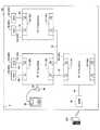
図1は、本実施形態に係る車載ネットワークシステム1の構成の一例を概略的に示す図である。本実施形態に係る車載ネットワークシステム1は、車両100に搭載され、イーサネットプロトコルに基づく車載ネットワークを構成し、相互に通信可能な複数(本例では、3個)のゲートウェイECU(Electronic Control Unit)10と、車両の各種制御を行う複数(本例では、4個)のECU20と、ダイアグツール30と、DCM(Data Communication Module)40とを含む。 FIG. 1 is a diagram schematically illustrating an example of a configuration of an in-vehicle network system 1 according to the present embodiment. An in-vehicle network system 1 according to the present embodiment is mounted on a
ゲートウェイECU10(中継装置の一例)は、異なるローカルネットワーク間、或いは、ECU20に応答要求を行う機器(ダイアグツール30、DCM40)とECU20が属するローカルネットワークとの間の通信の中継を行う。ゲートウェイECU10は、ECU20が属するローカルネットワーク、及びECU20に応答要求を行う機器(ダイアグツール30、DCM40)の何れか一方が接続される。ゲートウェイECU10は、他のローカルネットワークに対応するゲートウェイECU10と通信線15を介して接続するためのL3(Layer 3)スイッチ11と、自己を含むローカルネットワークを構成するECU20と通信線25を介して接続するためのL2(Layer 2)スイッチ12を含む。ゲートウェイECU10は、3つのゲートウェイECU10A〜10Cを含み、L3スイッチ11及びL2スイッチ12は、それぞれ、ゲートウェイECU10A〜10Cに対応するL3スイッチ11A〜11C及びL2スイッチ12A〜12Cを含む。 The gateway ECU 10 (an example of a relay device) relays communication between different local networks or between a device that makes a response request to the ECU 20 (the
ゲートウェイECU10Aは、専用の通信線45を介してDCM40と接続される。また、ゲートウェイECU10Aは、L3スイッチ11AのポートP1に繋がる通信線15を介してゲートウェイECU10Bと接続される。即ち、ゲートウェイECU10Aは、DCM40と、他のゲートウェイECU10(ゲートウェイECU10B,10C)に接続されるECU20(を含む他のローカルネットワーク)やダイアグツール30との間の通信を中継する。 The
尚、DCM40は、通信線25を介してL2スイッチ12AのポートP1,P2の何れかに接続され、ゲートウェイECU10Aと共に、イーサネットプロトコルに基づくローカルネットワークを構成してもよい。また、ゲートウェイECU10AのL2スイッチ12AのポートP1,P2には、通信線25を介して他のECU20が接続され、ゲートウェイECU10A、及び該ECU20を含む、イーサネットプロトコルに基づくローカルネットワークを構成してもよい。 The
ゲートウェイECU10Bは、専用の通信線35を介してダイアグツール30と接続可能に構成される。具体的には、通信線35の一端がゲートウェイECU10Bの所定のインターフェースに接続され、通信線35の他端には、接続コネクタ36が設けられる。そして、ダイアグツール30の接続コードの先端に設けられるコネクタ(不図示)と接続コネクタ36とを繋ぐことにより、ゲートウェイECU10Bとダイアグツール30との間が通信可能に接続される。また、ゲートウェイECU10Bは、L3スイッチ11BのポートP1,P2の各々に繋がる通信線15を介してゲートウェイECU10A,10Cと接続される。また、ゲートウェイECU10Bは、L2スイッチ12BのポートP1,P2の各々に繋がる通信線25を介してECU20(ECU20A,20B)と接続され、ECU20A,20Bを含む、イーサネットプロトコルに基づくローカルネットワークを構成する。即ち、ゲートウェイECU10Bは、ダイアグツール30と、他のゲートウェイECU10(10A,10C)に接続されるECU20(が含まれるローカルネットワーク)との間の通信を中継する。また、ゲートウェイECU10Bは、ダイアグツール30と、ゲートウェイECU10Bに接続されるECU20A,20B(を含むローカルネットワーク)との間の通信を中継する。また、ゲートウェイECU10Bは、ECU20A,20Bを含むローカルネットワークと、他のゲートウェイECU10(ゲートウェイECU10C)に接続されるECU20(を含む他のローカルネットワーク)やDCM40との間の通信を中継する。 The
尚、ゲートウェイECU10Bと共に、ローカルネットワークを構成するECU20の個数は、2個に限定されず、1個でもよいし、3個以上であってもよい。例えば、L2スイッチ12BのポートP1,P2以外の他のポートがある場合、該他のポートに通信線25を介して更にECU20が接続されてもよい。また、L2スイッチ12BのポートP1,P2の少なくとも一方に、ECU20の代わりに、通信線25を介して他のL2スイッチの一のポートが接続された上で、該L2スイッチの複数の他のポートの各々に通信線25を介してECU20が接続されてもよい。これらは、後述するゲートウェイECU10Cについても同様である。また、ダイアグツール30は、通信線25を介してL2スイッチ12AのポートP1,P2以外の他のポートに接続され、ゲートウェイECU10B、ECU20A,20Bと共に、イーサネットプロトコルに基づくローカルネットワークを構成してもよい。 In addition, the number of ECU20 which comprises a local network with gateway ECU10B is not limited to two, One may be sufficient and three or more may be sufficient. For example, when there are other ports other than the ports P1 and P2 of the
ゲートウェイECU10Cは、L3スイッチ11CのポートP1に繋がる通信線15を介してゲートウェイECU10Bと接続される。また、ゲートウェイECU10Cは、L2スイッチ12CのポートP1,P2の各々に繋がる通信線25を介してECU20(ECU20C,20D)と接続される。即ち、ゲートウェイECU10Cは、ECU20C,20Dを含むローカルネットワークと、他のゲートウェイECU10(10A,10B)に接続されるECU20(を含む他のローカルネットワーク)やダイアグツール30、DCM40との間の通信を中継する。
ECU20は、車両100(例えば、車両100に搭載される車載装置)の制御を行う電子制御ユニットである。ECU20は、例えば、エンジンECU、トランスミッションECU、エアコンECU、ブレーキECU、パワステECU、メータECU、ナビゲーションECU、ボディECU等、各種ECUを含む。ECU20は、例えば、CPU,RAM,ROM,I/Oを含むマイクロコンピュータを中心として構成されてよく、ROMに格納される各種プログラムをCPU上で実行することにより各種制御処理を実現できる。また、例えば、ECU20は、自己診断機能を有し、制御対象である車載装置、アクチュエータ、センサ等に異常が発生した場合、異常発生時のセンサの検出値、車載装置或いはアクチュエータへの制御信号等のデータを内部メモリに記憶させる処理を行う。また、例えば、ECU20は、車両100における所定のイベント(運転者による急制動が行われたこと、ABS(Anti-Lock Braking System)が作動したこと等)が発生したときに、そのイベントに対応して予め規定された特定のセンサの検出値や各種ECUによる制御信号等を内部メモリに記憶させる処理を行う。ECU20は、上述の如く、ゲートウェイECU10BのL2スイッチ12Bに接続されるECU20A,20Bと、ゲートウェイECU10CのL2スイッチ12Cに接続されるECU20C,20Dを含む。 The
尚、本実施形態において、ECU20は、複数のゲートウェイECU10(10B,10C)に接続されるが、1つのゲートウェイECU10(例えば、ゲートウェイECU10C)だけに接続されてもよいし、3つ以上のゲートウェイECU10(例えば、上述の如く、ゲートウェイECU10B,10Cに加えて、ゲートウェイECU10A)に接続されてもよい。即ち、ECU20は、複数のゲートウェイECU10のうちの少なくとも1つに接続されていればよい。 In the present embodiment, the
ダイアグツール30(要求装置の一例)は、車両100の車載ネットワークシステム1(具体的には、ゲートウェイECU10)に接続可能な外部接続機器の一例である。具体的には、ダイアグツール30は、一時的に車両100の車載ネットワークシステム1に接続され、車両100の故障診断(ダイアグ)に関する処理を行う。ダイアグツール30は、複数のゲートウェイECU10(ゲートウェイECU10A〜10C)のうちの予め規定された1つに接続される。本実施形態では、上述の如く、先端にコネクタを有する接続コードを有し、コネクタをゲートウェイECU10Bに接続される専用の通信線35の先端に設けられる接続コネクタ36に結合させることができる。ダイアグツール30は、接続コネクタ36及び通信線35を介してゲートウェイECU10Bと接続されることにより、ECU20(ECU20A〜20D)に対する応答要求を、ゲートウェイECU10Bを介して、送信することができる。 The diagnostic tool 30 (an example of a request device) is an example of an externally connected device that can be connected to the in-vehicle network system 1 (specifically, the gateway ECU 10) of the
DCM40(要求装置の他の例)は、車両100の遠隔に設けられるセンタサーバ200と無線通信回線(例えば、携帯電話網等)を通じて双方向通信を行う通信装置である。DCM40は、ダイアグツール30と同様、複数のゲートウェイECU10(ゲートウェイECU10A〜10C)のうちの予め規定された1つに接続する。本実施形態では、DCM40は、ゲートウェイECU10Aに接続され、センタサーバ200から送信される要求信号(即ち、車両100のECUに対する応答要求)に応じて、ECU20(ECU20A〜20D)に対する応答要求を、ゲートウェイECU10Aを介して送信する。センタサーバ200は、例えば、DCM40を介して、ECU20から受信する各種データ(故障診断データやログデータ)に基づき、車両100の異常や故障の原因の解析、車両100の異常動作の発生状況の解析等を行ってよい。DCM40から送信される応答信号は、ダイアグツール30から送信される応答信号と同内容或いは同種類の応答信号を含む。ダイアグツール30及びDCM40の双方から送信される同内容或いは同種類の応答要求は、ECU20に対するデータの読み出し要求であってよく、例えば、故障診断に関するデータ(FFD(Freezed Frame Data)等)の読み出し要求、所定のイベント発生時のセンサの検出信号或いは各種ECUの制御信号のログデータの読み出し要求を含んでよい。また、ダイアグツール30及びDCM40の双方から送信される同内容或いは同種類の応答要求は、データの書き換え要求であってよく、例えば、ECU20にインストールされる各種プログラムのアップデート要求(リプログラム要求、書き換え要求)を含んでよい。 The DCM 40 (another example of the requesting device) is a communication device that performs bidirectional communication with a
尚、本実施形態では、ECU20に対する同内容或いは同種類の応答要求を送信する要求装置は、ダイアグツール30、DCM40の2つであるが、3つ以上であってもよい。例えば、追加される要求装置は、車両100の製造メーカが製造する純正のダイアグツール30とは異なる民生ツール、リプロツール、パソコン、携帯端末(スマートフォン等)であってよく、ゲートウェイECU10A〜10Cのうちの予め規定された1つ(例えば、ゲートウェイECU10C)に接続されてよい。この場合、追加される要求装置は、ダイアグツール30のように、ゲートウェイECU10に対して一時的に接続可能な態様であってもよいし、DCM40のように、ゲートウェイECU10と常時接続されている態様であってもよい。即ち、要求装置は、ゲートウェイECU10A〜10Cのうちの予め規定された何れか1つに接続可能であればよい。 In the present embodiment, there are two request devices that transmit the same content or the same type of response request to the
次に、図2を参照して、ゲートウェイECU10(10A〜10C)の機能構成について説明をする。 Next, the functional configuration of the gateway ECU 10 (10A to 10C) will be described with reference to FIG.
図2は、本実施形態に係るゲートウェイECU10(10A〜10C)の構成の一例を示す機能ブロック図である。 FIG. 2 is a functional block diagram showing an example of the configuration of the gateway ECU 10 (10A to 10C) according to the present embodiment.
複数のゲートウェイECU10、即ち、ゲートウェイECU10A〜10Cは、それぞれ、同じハードウェア及び同じ機能(ソフトウェア)を含んで構成されてよい。即ち、ゲートウェイECU10A〜10Cは、車載ネットワークシステム1内における接続場所、及び車両100におけるレイアウト場所が異なるだけで、同一の機能を有するハードウェアであってよい。これにより、部品の種類数の増加を抑制できるため、ゲートウェイECU10の部品コストを抑制できる。以下、ゲートウェイECU10は、全て同一の機能を有する前提で説明を行う。 The plurality of
ゲートウェイECU10は、その機能が任意のハードウェア、ソフトウェア、或いはこれらの組み合わせにより実現されてよく、ECU20と同様、例えば、CPU,RAM,ROM,I/Oを含むマイクロコンピュータを中心に構成されてよい。ゲートウェイECU10は、図2に示すように、ROMに格納される各種プログラムをCPU上で実行することにより実現される機能部として、第1送信処理部101、第1受信処理部102、第2送信処理部103、第2受信処理部104、第3送信処理部105、第3受信処理部106、マスタ設定処理部107、調停処理部108を含む。また、ゲートウェイECU10は、例えば、EEPROM(Electrically Erasable Programmable Read Only Memory)等の不揮発性の内部メモリに規定される記憶領域としての記憶部110を含む。また、第1送信処理部101、第1受信処理部102、第2送信処理部103、第2受信処理部104、第3送信処理部105、第3受信処理部106、マスタ設定処理部107、調停処理部108、記憶部110は、それぞれ、ゲートウェイECU10A〜10Cに対応する、第1送信処理部101A〜101C、第1受信処理部102A〜102C、第2送信処理部103A〜103C、第2受信処理部104A〜104C、第3送信処理部105A〜105C、第3受信処理部106A〜106C、マスタ設定処理部107A〜107C、調停処理部108A〜108C、記憶部110A〜110Cを含む。 The
第1送信処理部101(第1送信部及び第2送信部の一例)は、L3スイッチ11を通じて、自己が含まれるゲートウェイECU10以外の他のゲートウェイECU10に信号を送信する処理を行う。例えば、第1送信処理部101(101B)は、自己が含まれるゲートウェイECU10が、後述するマスタとして設定されていない場合、要求装置(ダイアグツール30)が、自己が含まれるゲートウェイECU10(10B)に接続されたときに、その旨を示す接続情報をマスタとして設定されているゲートウェイECU10に送信する。自己が含まれるゲートウェイECU10がマスタであるか否かは、後述するマスタフラグFの値で把握することができる。また、例えば、第1送信処理部101(101A,101B)は、要求装置(ダイアグツール30、DCM40)から、自己が含まれるゲートウェイECU10以外の他のゲートウェイECU10に接続するECU20への応答要求を、宛先であるECU20が接続する他のゲートウェイECU10に向けて送信(転送)する。 The first transmission processing unit 101 (an example of the first transmission unit and the second transmission unit) performs a process of transmitting a signal to the
第1受信処理部102(第1受信部及び第2受信部の一例)は、他のゲートウェイECU10から送信された信号を、L3スイッチ11を通じて、受信する処理を行う。例えば、第1受信処理部102は、自己が含まれるゲートウェイECU10以外の他のゲートウェイECU10から送信(転送)される、要求装置(ダイアグツール30、DCM40)からの応答要求を受信する。また、例えば、第1受信処理部102は、自己が含まれるゲートウェイECU10以外の他のゲートウェイECU10から、後述するマスタ情報を受信する。また、例えば、第1受信処理部102は、自己が含まれるゲートウェイECU10がマスタとして設定されている場合、自己が含まれるゲートウェイECU10以外の他のゲートウェイECU10から上記接続情報を受信する。 The first reception processing unit 102 (an example of a first reception unit and a second reception unit) performs a process of receiving a signal transmitted from another
第2送信処理部103は、L2スイッチ12を通じて、自己が含まれるゲートウェイECU10に接続されるECU20(即ち、自己が含まれるゲートウェイECU10を含むローカルネットワーク)に信号を送信する処理を行う。例えば、第2送信処理部103(103B,103C)は、自己が含まれるゲートウェイECU10に接続されるECU20に対する要求装置(ダイアグツール30、DCM40)からの応答要求を、対象となるECU20に送信(転送)する。 The second
第2受信処理部104は、自己が含まれるゲートウェイECU10に接続されるECU20(即ち、ローカルネットワーク)から送信される信号を、L2スイッチ12を通じて、受信する処理を行う。例えば、第2受信処理部104(104B,104C)は、要求装置(ダイアグツール30、DCM40)からの応答要求に応じてローカルネットワークのECU20から送信される応答信号を受信する。 The second
第3送信処理部105は、自己が含まれるゲートウェイECU10に接続される要求装置に信号(例えば、応答要求に対して、ECU20から返信される応答信号)を送信する処理を行う。 The third
第3受信処理部106は、自己が含まれるゲートウェイECU10に接続される要求装置からの信号(応答要求)を受信する処理を行う。 The third
マスタ設定処理部107(マスタ設定部の一例)は、予め規定されたタイミング(例えば、車両100の完成時、或いは、車両100のイグニッションオン(IG−ON)時)以降における要求装置のゲートウェイECU10に対する接続状況(接続履歴)に基づき、ゲートウェイECU10A〜10Cの中から1つのマスタを設定する処理を行う。また、マスタ設定処理部107は、ゲートウェイECU10A〜10Cの中からマスタを設定した場合、自己が含まれるゲートウェイECU10以外の他のゲートウェイECU10に、マスタとして設定したゲートウェイECU10に関するマスタ情報を送信する送信要求を第1送信処理部101に送る。これにより、他のゲートウェイECU10は、マスタとして設定されたゲートウェイECU10を認知することができる。 The master setting processing unit 107 (an example of a master setting unit) is configured for the
マスタは、上記タイミング(車両100の完成時或いは車両100のIG−ON時)では、設定されておらず(即ち、マスタフラグFは、初期状態の"0"であり)、マスタ設定処理部107は、マスタが設定されていない場合、自己が含まれるゲートウェイECU10に要求装置が接続されたときに、自己が含まれるゲートウェイECU10をマスタとして設定する。上述の如く、ダイアグツール30は、一時的に接続可能な態様であるが、DCM40は、常時接続されている。そのため、マスタが設定されていない状態で、車両100がIG−ONされると、ゲートウェイECU10Aのマスタ設定処理部107Aは、DCM40がゲートウェイECU10Aに接続されたと判断し、ゲートウェイECU10Aをマスタとして設定する。そして、マスタ設定処理部107(107A)は、自己が含まれるゲートウェイECU10(10A)をマスタとして設定した旨を示すマスタ情報を、他のゲートウェイECU10(10B,10C)に送信する送信要求を第1送信処理部101(101A)に送る。 The master is not set at the above timing (when the
また、マスタ設定処理部107は、自己が含まれるゲートウェイECU10がマスタとして設定されている場合、第1受信処理部102が、自己が含まれるゲートウェイECU10以外の他のゲートウェイECU10から要求装置が接続された旨の接続情報を受信したときに、記憶部110に記憶される優先度情報1101に基づき、マスタの設定を行う。優先度情報1101は、複数の要求装置(ダイアグツール30、DCM40)の各々から送信される応答要求の調停処理における優先度を表す情報であり、優先度情報1101には、複数の要求装置の各々の優先度が規定されている。具体的には、マスタ設定処理部107は、複数の要求装置(ダイアグツール30、DCM40)が、上記タイミング以降で接続されたことがあるゲートウェイECU10(10A〜10C)のうち、優先度情報1101に規定される優先度が最も高い要求装置が接続されたことがあるゲートウェイECU10をマスタに設定する。上述の如く、ダイアグツール30は、一時的にゲートウェイECU10Bに接続可能な態様である。そのため、車両100の修理施設(ディーラ、サービス工場等)にて、上記タイミング以降で初めてダイアグツール30が接続されると、マスタとして設定されているゲートウェイECU10A(第1受信処理部102A)は、ゲートウェイECU10Bからダイアグツール30が接続された旨の接続情報を受信する。そして、ゲートウェイECU10Aのマスタ設定処理部107Aは、ダイアグツール30とDCM40のうちの優先度情報1101に規定される優先度が高い方が接続されたことがあるゲートウェイECU10(ゲートウェイECU10A,10Bの何れか)をマスタに設定する。本実施形態では、優先度情報1101において、ダイアグツール30の優先度の方が、DCM40の優先度よりも高く設定される。通常、ダイアグツール30は、車両100の点検・修理に関する用途で用いられるため、センタサーバ200からの要求よりも、実際に車両100の点検・修理が行われる現場における応答要求を優先すべきと考えうるからである。そのため、ゲートウェイECU10Aのマスタ設定処理部107Aは、優先度が最も高いダイアグツール30が接続されたことがあるゲートウェイECU10Bをマスタとして設定する。そして、マスタ設定処理部107(107A)は、ゲートウェイECU10Bをマスタとして設定した旨を示すマスタ情報を、他のゲートウェイECU10(10B,10C)に送信する送信要求を第1送信処理部101(101A)に送る。 In addition, when the
このように、本実施形態では、ゲートウェイECU10の何れか1つに要求装置(ダイアグツール30、DCM40)が接続されたタイミングで、マスタの設定が行われる。そのため、ゲートウェイECU10A〜10Cと複数の要求装置(ダイアグツール30、DCM40)との間の接続状況に応じて、適切にマスタの設定を行うことができる。 Thus, in the present embodiment, the master is set at the timing when the requesting device (
尚、本実施形態では、優先度情報1101に規定される優先度は、例えば、優先度が高いことを示す"高"と優先度が低いことを示す"低"の2種類が設けられ、ダイアグツール30が"高"、DCM40が"低"に設定されている。また、要求装置が3つ以上設けられる場合は、更に、多段階の優先度が設けられる(例えば、3つの要求装置に対しては、更に、中程度の優先度を示す"中"が設けられる)。 In the present embodiment, the priority levels defined in the
また、マスタ設定処理部107は、マスタが設定されているか、及びマスタが設定されている場合、自己が含まれるゲートウェイECU10がマスタであるか否かを示すマスタフラグF(F=0:マスタ未設定、F=1:自己が含まれるゲートウェイECU10以外がマスタ、F=2:自己が含まれるゲートウェイECU10がマスタ)の管理を行う。マスタフラグFは、記憶部110に記憶され、初期値が、マスタが設定されていないことを表す"0"であり、マスタが設定される度に更新される。具体的には、マスタ設定処理部107は、自己がマスタを設定したとき、或いは、自己が含まれるゲートウェイECU10の第1受信処理部102が他のゲートウェイECU10からマスタ情報を受信したときに、記憶部110に記憶されるマスタフラグFの更新を行う。 In addition, the master
マスタ設定処理部107による処理の詳細は、更に後述する。 Details of the processing by the master
調停処理部108(調停部の一例)は、自己が含まれるゲートウェイECU10がマスタとして設定されている場合に、少なくとも2つの要求装置(ダイアグツール30及びDCM40)からの応答要求のうち、優先度情報1101に規定される優先度が最も高い要求装置(ダイアグツール30)からの応答要求が優先的にECU20に送信されるようにする調停処理を行う。これにより、例えば、同じECU20に対して、同内容或いは同種類の応答要求が非常に近しいタイミングで送信され、該ECU20の処理に悪影響が生じるような事態を抑制できる。具体的には、複数の同内容の応答要求を受信することにより、該ECU20の処理に混乱を生じさせたり、複数の同種類の応答要求を受信することにより、それぞれの内容に応じた応答信号をどのように返信すべきか判断できなくなったり等の悪影響を抑制することができる。例えば、上述の如く、ダイアグツール30が接続され、ゲートウェイECU10Bがマスタとして設定された場合、ゲートウェイECU10Bの調停処理部108Bは、第3受信処理部106がダイアグツール30からの応答要求を受信すると、ゲートウェイECU10Aに対して、DCM40との間での同様の応答要求に関する通信の遮断を指令する指令信号を送信する送信要求を第1送信処理部101Bに送る。これにより、ゲートウェイECU10Aは、第1送信処理部101Bから送信される指令信号に応じて、DCM40との間でのECU20に対する応答要求に関する通信を遮断するため、ダイアグツール30からの応答要求だけが優先的にECU20に送信される。 The arbitration processing unit 108 (an example of the arbitration unit), when the
次に、図3を参照して、本実施形態に係るマスタ設定処理部107による具体的な処理フローについて説明をする。 Next, a specific processing flow by the master
図3は、マスタ設定処理部107によるマスタ設定処理の一例を概略的に示すフローチャートである。本フローチャートによる処理は、例えば、処理対象のマスタ設定処理部107が含まれるゲートウェイECU10の作動中(例えば、車両100のIG−ONからIG−OFFまでの間)で、定期的に実行されてよい。 FIG. 3 is a flowchart schematically showing an example of the master setting process by the master
ステップS102にて、マスタ設定処理部107は、マスタフラグFが"0"であるか否か、即ち、マスタが設定されていない状態か否かを判定する。マスタ設定処理部107は、マスタフラグFが0である場合、ステップS104に進み、マスタフラグFが0でない("1"或いは"2"である)場合、ステップS112に進む。 In step S102, the master
ステップS104にて、マスタ設定処理部107は、自己が含まれるゲートウェイECU10に要求装置が接続されたか否かを判定する。マスタ設定処理部107は、要求装置が接続された場合、ステップS106に進み、要求装置が接続されていない場合、今回の処理を終了する。 In step S104, master setting
ステップS106にて、マスタ設定処理部107は、自己が含まれるゲートウェイECU10をマスタとして設定する。 In step S106, master setting
そして、ステップS108にて、マスタ設定処理部107は、マスタフラグFを"2"に更新する。 In step S108, the master
ステップS110にて、マスタ設定処理部107は、第1送信処理部101を介して、自己が含まれるゲートウェイECU10以外の他のゲートウェイECU10にマスタとして設定されたゲートウェイECU10に関するマスタ情報を送信し、今回の処理を終了する。 In step S110, the master
一方、ステップS112にて、マスタ設定処理部107は、第1受信処理部102が、自己が含まれるゲートウェイECU10以外の他のゲートウェイECU10から要求装置が接続された旨の接続情報を受信したか否かを判定する。マスタ設定処理部107は、第1受信処理部102が接続情報を受信した場合、ステップS114に進み、接続情報を受信していない場合、今回の処理を終了する。 On the other hand, in step S112, master setting
尚、上述の如く、接続情報は、マスタとして設定されていないゲートウェイECU10(の第1送信処理部101)からマスタとして設定されているゲートウェイECU10に送信される。そのため、接続情報を受信した第1受信処理部102を含むゲートウェイECU10は、マスタとして設定されている。 As described above, the connection information is transmitted from the gateway ECU 10 (the first transmission processing unit 101) not set as the master to the
ステップS114にて、マスタ設定処理部107は、複数の要求装置の何れかが、上記タイミング(車両100の車両完成時、或いは、車両100のIG−ON時)以降で接続されたことがあるゲートウェイECU10のうち、優先度情報1101に規定される優先度が最も高い要求装置が接続されたことがあるゲートウェイECU10をマスタとして設定する。 In step S114, master setting
ステップS116にて、マスタ設定処理部107は、自己が含まれるゲートウェイECU10がマスタとして設定されたか否かを判定する。マスタ設定処理部107は、自己が含まれるゲートウェイECU10が、マスタとして設定された場合、ステップS118に進み、マスタとして設定されなかった場合、ステップS120に進む。 In step S116, master setting
ステップS118にて、マスタ設定処理部107は、マスタフラグF2を"2"に設定(更新)し、ステップS110に進む。 In step S118, master setting
一方、ステップS120にて、マスタ設定処理部107は、マスタフラグF2を"1"に設定(更新)し、ステップS110に進む。 On the other hand, in step S120, the master
尚、上述の如く、マスタ設定処理部107は、本フローによる処理以外、自己が含まれるゲートウェイECU10(第1受信処理部102)が他のゲートウェイECU10からマスタ情報を受信した場合にも、マスタフラグFの設定(更新)を行う。 Note that, as described above, the master
そして、ステップS110にて、マスタ設定処理部107は、第1送信処理部101を介して、自己が含まれるゲートウェイECU10以外の他のゲートウェイECU10にマスタとして設定されたゲートウェイECU10に関するマスタ情報を送信し、今回の処理を終了する。 In step S110, the master
このように、本実施形態では、車載ネットワークシステム(マスタ設定処理部107)は、複数の要求装置(ダイアグツール30、DCM40)の何れかが、予め規定されたタイミング(車両100の車両完成時、或いは、車両100のIG−ON時)以降で接続されたことがあるゲートウェイECU10のうち、優先度情報1101に規定される優先度が最も高い要求装置が接続されたことがあるゲートウェイECU10をマスタとして設定する。そして、ゲートウェイECU10(調停処理部108)は、マスタとして設定されている場合、複数の要求装置のうちの少なくとも2つから応答要求が送信されたときに、優先度が最も高い要求装置からの応答要求が優先的にECU20に送信されるように調停を行う。従って、イーサネットプロトコルに基づく車載ネットワークのように、複数の要求装置が接続されうるゲートウェイECU10が複数ある場合であっても、複数のゲートウェイECU10の中から自動的にマスタとなるゲートウェイECU10を設定することができる。また、車両100の各種仕様(例えば、右ハンドル車、左ハンドル車等の別)に依って、複数のゲートウェイECU10のレイアウト等が異なり、どのゲートウェイECU10にどの要求装置が接続するかが変更される場合であっても、事後的に(車両100の車両完成後に)、複数のゲートウェイECU10の中から自動的にマスタとなるゲートウェイECU10を設定することができる。そのため、マスタとして設定されたゲートウェイECU10は、複数の要求装置からの応答信号に関する調停処理を適切に行うことができる。また、マスタとして設定されるゲートウェイECU10には、複数の要求装置の中で最も調停処理における優先度が高い要求装置が接続される。そのため、優先度が高い要求装置からの応答要求に対応する調停処理を行い易くなる。 As described above, in the present embodiment, the in-vehicle network system (master setting processing unit 107) is configured so that any one of the plurality of requesting devices (
[第2実施形態]
次いで、第2実施形態について説明する。[Second Embodiment]
Next, a second embodiment will be described.
第2実施形態に係る車載ネットワークシステム1は、ゲートウェイECU10が優先度設定処理部109(図4参照)を更に含む点において、第1実施形態と主に異なる。以下、第1実施形態と同様或いは対応する構成には、同一の符号を付し、第1実施形態と異なる部分を中心に説明する。 The in-vehicle network system 1 according to the second embodiment is mainly different from the first embodiment in that the
図4は、本実施形態に係るゲートウェイECU10の構成の一例を示す機能ブロック図である。 FIG. 4 is a functional block diagram showing an example of the configuration of the
ゲートウェイECU10は、図4に示すように、ROMに格納される各種プログラムをCPU上で実行することにより実現される機能部として、第1送信処理部101、第1受信処理部102、第2送信処理部103、第2受信処理部104、第3送信処理部105、第3受信処理部106、マスタ設定処理部107、調停処理部108、優先度設定処理部109を含む。また、ゲートウェイECU10は、例えば、EEPROM等の不揮発性の内部メモリに規定される記憶領域としての記憶部110を含む。また、第1送信処理部101、第1受信処理部102、第2送信処理部103、第2受信処理部104、第3送信処理部105、第3受信処理部106、マスタ設定処理部107、調停処理部108、優先度設定処理部109、記憶部110は、それぞれ、ゲートウェイECU10A〜10Cに対応する、第1送信処理部101A〜101C、第1受信処理部102A〜102C、第2送信処理部103A〜103C、第2受信処理部104A〜104C、第3送信処理部105A〜105C、第3受信処理部106A〜106C、マスタ設定処理部107A〜107C、調停処理部108A〜108C、優先度設定処理部109A〜109C、記憶部110A〜110Cを含む。 As shown in FIG. 4, the
マスタ設定処理部107は、第1実施形態で示したタイミングに加えて、優先度設定処理部109により優先度情報1101に規定される、複数の要求装置(ダイアグツール30、DCM40)の各々の優先度が変更された場合に、マスタ設定処理を行う。詳細は、後述する。 In addition to the timing shown in the first embodiment, the master
優先度設定処理部109は、車両100の位置或いは状態(車両状態)等に応じて、優先度情報1101に規定される、複数の要求装置(ダイアグツール30、DCM40)の各々の優先度を設定変更する。以下、図5〜図7を参照して、優先度設定処理部109による優先度設定処理について説明をする。 The priority
まず、図5は、本実施形態に係る優先度設定処理部109による優先度設定処理の一例を概略的に示すフローチャートである。本フローチャートによる処理は、例えば、処理対象の優先度設定処理部109が含まれるゲートウェイECU10の作動中(例えば、車両100のIG−ONからIG−OFFまでの間)で、定期的に実行されてよい。 First, FIG. 5 is a flowchart schematically showing an example of priority setting processing by the priority
尚、優先度情報1101の上記タイミング(車両100の車両完成時、或いは、車両100のIG−ON時)における初期状態は、ダイアグツール30の優先度がDCM40の優先度よりも高い(ダイアグツール30が"高"で、DCM40が"低"である)ダイアグツール優先であることを前提にする。 In the initial state of the
ステップS202にて、優先度設定処理部109は、優先度情報1101の内容に基づき、ダイアグツール優先であるか否かを判定する。優先度設定処理部109は、ダイアグツール優先でない(即ち、DCM40の優先度がダイアグツール30の優先度より高いDCM優先である)場合、ステップS204に進み、ダイアグツール優先である場合、ステップS208に進む。 In step S202, the priority
ステップS204にて、優先度設定処理部109は、車両100が修理施設(例えば、ディーラやサービス工場等)に入庫しているか否かを判定する。例えば、優先度設定処理部109は、車両100のナビゲーション装置(GPSセンサ及び地図データベース)から取得可能な車両100の位置情報及び施設情報等に基づき、車両100が修理施設に入庫しているか否かを判定してよい。また、例えば、優先度設定処理部109は、修理施設に固有で設けられる通信機器(例えば、Wi−Fi(登録商標)ルータ)と車両100に設けられる対応する通信機器との間での接続状況を確認することにより、車両100が修理施設に入庫しているか否かを判定してよい。優先度設定処理部109は、車両100が修理施設に入庫している場合、ステップS206に進み、入庫していない場合、今回の処理を終了する。 In step S204, the priority
ステップS206にて、優先度設定処理部109は、優先度情報1101をダイアグツール優先、即ち、ダイアグツール30が"高"、且つ、DCM40が"低"に設定変更し、今回の処理を終了する。 In step S206, the priority
一方、ステップS208にて、優先度設定処理部109は、車両100が修理施設に入庫しているか否かを判定する。優先度設定処理部109は、車両100が修理施設に入庫していない場合、ステップS210に進み、入庫している場合、今回の処理を終了する。 On the other hand, in step S208, the priority
ステップS210にて、優先度設定処理部109は、優先度情報1101をDCM優先、即ち、ダイアグツール30が"低"、且つ、DCM40が"高"に設定変更し、今回の処理を終了する。 In step S210, the priority
このように、本例では、優先度設定処理部109は、車両100が修理施設に入庫している場合、優先度情報1101をダイアグツール優先に設定し、車両100が修理施設に入庫していない場合、DCM優先に設定する。従って、車両100が修理施設に入庫している場合、上述の如く、ダイアグツール30が点検・修理の用途で用いられる可能性が高いため、ダイアグツール優先として、ダイアグツール30が接続されたことがあるゲートウェイECU10(10B)をマスタとして設定し、ダイアグツール30からの応答要求をDCM40からの応答要求よりも優先する調停処理を行うことができる。一方、車両100が修理施設に入庫していない場合、ダイアグツール30が点検・修理の用途で使用される可能性が低いと考えられるため、DCM優先として、DCM40からの応答要求をダイアグツール30からの応答要求よりも優先する調停処理を行うことができる。 As described above, in this example, when the
続いて、図6は、本実施形態に係る優先度設定処理部109による優先度設定処理の他の例を概略的に示すフローチャートである。本フローチャートによる処理は、図5の場合と同様、例えば、処理対象の優先度設定処理部109が含まれるゲートウェイECU10の作動中(例えば、車両100のIG−ONからIG−OFFまでの間)で、定期的に実行されてよい。 Next, FIG. 6 is a flowchart schematically showing another example of the priority setting process by the priority
ステップS302にて、優先度設定処理部109は、優先度情報1101の内容に基づき、ダイアグツール優先であるか否かを判定する。優先度設定処理部109は、ダイアグツール優先でない(即ち、DCM優先である)場合、ステップS304に進み、ダイアグツール優先である場合、ステップS310に進む。 In step S <b> 302, the priority
ステップS304にて、優先度設定処理部109は、車両100が停車中であるか否かを判定する。優先度設定処理部109は、例えば、車両100に搭載される車速センサ(不図示)から取得可能な検出信号に基づき、車両100が停車しているか、走行しているかを判断することができる。優先度設定処理部109は、車両100が停車中である場合、ステップS306に進み、車両100が停車中でない(即ち、走行中である)場合、今回の処理を終了する。 In step S304, the priority
ステップS306にて、優先度設定処理部109は、ダイアグツール30が何れかのゲートウェイECU10(本実施形態では、ゲートウェイECU10B)に接続されているか否かを判定する。優先度設定処理部109は、ダイアグツール30が何れかのゲートウェイECU10に接続されている場合、ステップS308に進み、接続されていない場合、今回の処理を終了する。 In step S306, the priority
尚、本例の場合、第1送信処理部101(101B)は、要求装置(ダイアグツール30)が、自己が含まれるゲートウェイECU10(10B)に接続されたときに、その旨を示す接続情報を全てのゲートウェイECU10(ゲートウェイECU10A,10C)に送信するようにするとよい。これにより、全てのゲートウェイECU10の優先度設定処理部109は、ダイアグツール30が接続されているか否かを判定できる。 In the case of this example, the first transmission processing unit 101 (101B) provides connection information indicating that when the requesting device (diagnostic tool 30) is connected to the gateway ECU 10 (10B) including itself. It is good to transmit to all gateway ECU10 (gateway ECU10A, 10C). Thereby, the priority
ステップS308にて、優先度設定処理部109は、優先度情報1101をダイアグツール優先、即ち、ダイアグツール30が"高"、且つ、DCM40が"低"に設定変更し、今回の処理を終了する。 In step S308, the priority
一方、ステップS310にて、優先度設定処理部109は、車両100が走行中であるか否かを判定する。優先度設定処理部109は、車両100が走行中でない(即ち、停車中である)場合、ステップS312に進み、車両100が走行中である場合、ステップS314に進む。 On the other hand, in step S310, the priority
ステップS314にて、優先度設定処理部109は、ダイアグツール30が何れかのゲートウェイECU10(本実施形態では、ゲートウェイECU10B)に接続されているか否かを判定する。優先度設定処理部109は、ダイアグツール30が何れかのゲートウェイECU10に接続されていない場合、ステップS314に進み、接続されている場合、今回の処理を終了する。 In step S314, the priority
ステップS314にて、優先度設定処理部109は、優先度情報1101をDCM優先、即ち、ダイアグツール30が"低"、且つ、DCM40が"高"に設定変更し、今回の処理を終了する。 In step S314, the priority
このように、本例では、優先度設定処理部109は、車両100が停車しており、且つ、ダイアグツール30が複数のゲートウェイECU10の何れかに接続されている場合、優先度情報1101をダイアグツール優先に設定する。車両100が停車し、且つ、ダイアグツール30が車両100に接続されている場合、車両100の点検・修理が行われる可能性が高いと考えられるからである。一方、優先度設定処理部109は、車両100が走行している場合、又はダイアグツール30が複数のゲートウェイECU10の何れにも接続されていない場合、優先度情報1101をDCM優先に設定する。車両100が走行中である、或いは、ダイアグツール30が車両100に接続されていない場合、車両100の点検・修理が行われる可能性が低いと考えられるからである。 As described above, in this example, the priority
続いて、図7は、本実施形態に係る優先度設定処理部109による優先度設定処理の更に他の例を概略的に示すフローチャートである。本フローチャートによる処理は、図5、図6の場合と同様、例えば、処理対象の優先度設定処理部109が含まれるゲートウェイECU10の作動中(例えば、車両100のIG−ONからIG−OFFまでの間)で、定期的に実行されてよい。 Next, FIG. 7 is a flowchart schematically showing still another example of the priority setting process by the priority
ステップS404〜S412の処理は、図5のステップS202〜S210の処理と同じである。以下、図5の処理と異なる部分を中心に説明をする。 The processing in steps S404 to S412 is the same as the processing in steps S202 to S210 in FIG. In the following, a description will be given focusing on parts different from the processing of FIG.
ステップS402にて、優先度設定処理部109は、車両100に異常(故障)が発生しているか否かを判定する。優先度設定処理部109は、例えば、車両100に搭載される、ECU20を含む各種ECUから取得可能なダイアグ情報等に基づき、車両100に異常が発生しているか否かを判定することができる。車両100の異常には、例えば、車両100に搭載される各種センサの検出値が予め規定される正常範囲を外れている状態が含まれる。具体的には、各種センサの検出値には、例えば、エンジンの水温センサの検出値、車両を駆動するモータの電流を検出する電流センサの検出値等が含まれる。優先度設定処理部109は、車両100に異常(故障)が発生していない場合、ステップS404に進み、図5と同様の処理を行う。一方、優先度設定処理部109は、車両100に異常(故障)が発生している場合、ステップS414に進む。 In step S402, the priority
ステップS414にて、優先度設定処理部109は、優先度情報1101の内容に基づき、ダイアグツール優先であるか否かを判定する。優先度設定処理部109は、ダイアグツール優先でない(即ち、DCM優先である)場合、ステップS408に進み、優先度情報1101をダイアグツール優先、即ち、ダイアグツール30が"高"、且つ、DCM40が"低"に設定変更し、今回の処理を終了する。一方、優先度設定処理部109は、ダイアグツール優先である場合、今回の処理を終了する。 In step S414, the priority
尚、本例では、図5の処理(ステップS202〜S210)に、ステップS402、414の処理を追加したが、同様に、図6の処理(ステップS302〜S314)に、ステップS402、414の処理を追加してもよい。この場合、ステップS414のNoのときは、ステップS308に相当する処理に進む。 In this example, the processes of steps S402 and 414 are added to the process of FIG. 5 (steps S202 to S210). Similarly, the processes of steps S402 and 414 are added to the process of FIG. 6 (steps S302 to S314). May be added. In this case, when No in step S414, the process proceeds to a process corresponding to step S308.
このように、本例では、優先度設定処理部109は、車両100に異常が発生していない場合、複数の要求装置(ダイアグツール30、DCM40)の優先度を所定の条件に応じて設定変更し、車両100に異常が発生している場合、車両100の所定の条件に依らず、ダイアグツール30の優先度をDCM40の優先度よりも高く設定する。これにより、車両100の位置や状態に応じて、複数の要求装置の優先度を変更できると共に、車両100が故障し、車両100の修理が必要な状況では、車両100の修理・点検に利用されるダイアグツール30の優先度を最も高くすることができる。 Thus, in this example, when the abnormality is not generated in the
次に、図8を参照して、本実施形態に係るマスタ設定処理部107による具体的な処理フローについて説明する。 Next, a specific processing flow by the master
図8は、本実施形態に係るマスタ設定処理部107によるマスタ設定処理の一例を概略的に示すフローチャートである。本フローチャートによる処理は、図3と同様、例えば、処理対象のマスタ設定処理部107が含まれるゲートウェイECU10の作動中(例えば、車両100のIG−ONからIG−OFFまでの間)で、定期的に実行されてよい。 FIG. 8 is a flowchart schematically showing an example of the master setting process by the master
本フローチャートのS502〜S520の処理は、図3のステップS102〜S120と同じである。以下、異なる部分を中心に説明する。 The processing from S502 to S520 in this flowchart is the same as steps S102 to S120 in FIG. The following description will focus on the different parts.
ステップS512にて、マスタ設定処理部107は、第1受信処理部102が、自己が含まれるゲートウェイECU10以外の他のゲートウェイECU10から要求装置が接続された旨の接続情報を受信していないと判定した場合、ステップS522に進む。 In step S512, master setting
ステップS522にて、マスタ設定処理部107は、自己が含まれるゲートウェイECU10の優先度設定処理部109により優先度情報1101の設定変更がされたか否かを判定する。マスタ設定処理部107は、優先度設定処理部109により優先度情報1101の設定変更がされた場合、ステップS524に進み、設定変更がされていない場合、今回の処理を終了する。 In step S522, master setting
ステップS524にて、マスタ設定処理部107は、マスタフラグFが"2"であるか否か、即ち、自己が含まれるゲートウェイECU10がマスタとして設定されているか否かを判定する。マスタ設定処理部107は、マスタフラグFが"2"である場合、ステップS514に進み、マスタの設定を行い、マスタフラグFが"2"でない("1"である)場合、今回の処理を終了する。 In step S524, master setting
このように、本実施形態では、マスタ設定処理部107は、自己が含まれるゲートウェイECU10がマスタとして設定されている場合、優先度情報1101が設定変更されたときに、複数のゲートウェイECU10(ゲートウェイECU10A〜10C)の中からマスタの選択(設定)を行う。これにより、優先度設定処理部109により設定変更された優先度情報1101に合わせて、マスタとして設定されるゲートウェイECU10を適切に変更することができる。 Thus, in this embodiment, when the
以上、本発明を実施するための形態について詳述したが、本発明はかかる特定の実施形態に限定されるものではなく、特許請求の範囲に記載された本発明の要旨の範囲内において、種々の変形・変更が可能である。 As mentioned above, although the form for implementing this invention was explained in full detail, this invention is not limited to this specific embodiment, In the range of the summary of this invention described in the claim, various Can be modified or changed.
[第1変形例]
例えば、上述した実施形態では、複数のゲートウェイECU10(10A〜10C)の全てに、マスタ設定処理部107及び優先度情報1101が含まれるが、複数のゲートウェイECU10のうちの一のゲートウェイECU10に設けられてもよい。この場合、一のゲートウェイECU10の第1受信処理部102(第3受信部の一例)は、一のゲートウェイECU10以外の他のゲートウェイECU10から、接続された要求装置に関する接続情報を受信する。また、一のゲートウェイECU10の第1送信処理部(第3送信部の一例)は、マスタ設定処理部107によりマスタが設定された場合、他のゲートウェイECU10に対して、マスタに設定されたゲートウェイECU10に関するマスタ情報を送信する。また、他のゲートウェイECU10の第1送信処理部101(第4送信部の一例)は、自己が含まれるゲートウェイECU10に対して、複数の要求装置の何れか1つが接続された場合、一のゲートウェイECU10に対して、接続された要求装置に関する接続情報を送信する。また、他のゲートウェイECU10の第1受信処理部102(第4受信部の一例)は、一のゲートウェイECU10から送信されるマスタ情報を受信する。かかる構成でも、上述した実施形態と同様の作用・効果を奏する。[First Modification]
For example, in the embodiment described above, the master
[第2変形例]
また、上述した実施形態では、複数のゲートウェイECU10に、マスタ設定処理部107及び優先度情報1101が含まれるが、車両100に搭載される、複数のゲートウェイECU10(ゲートウェイECU10A〜10C)と相互に通信可能な外部装置に含まれてもよい。この場合、外部装置は、複数のゲートウェイECU10の各々から、接続された要求装置に関する接続情報を受信する受信処理部(第5受信部の一例)と、マスタ設定処理部107によりマスタが設定された場合、複数のゲートウェイECU10の各々に対して、マスタに設定されたゲートウェイECU10に関するマスタ情報を送信する送信処理部(第5送信部の一例)を含む。また、各ゲートウェイECU10(ゲートウェイECU10A〜10C)は、複数の要求装置の何れか1つが、自己が含まれるゲートウェイECU10に接続された場合、外部装置に対して、接続された要求装置に関する接続情報を送信する第4送信処理部(第6送信部の一例)と、外部装置から送信されるマスタ情報を受信する第4受信処理部(第6受信部の一例)とを含む。かかる構成でも、上述した実施形態と同様の作用・効果を奏する。[Second Modification]
In the above-described embodiment, the plurality of
[第3変形例]
また、上述した第1実施形態及びその変形例では、優先度情報1101に規定される優先度のうち、ダイアグツール30の優先度が、DCM40の優先度よりも高く設定されるが、センタサーバ200からの応答要求を優先させたい場合は、逆に設定されてもよい。[Third Modification]
In the first embodiment described above and its modification, the priority of the
[第4変形例]
また、上述した第2実施形態及びその変形例では、優先度設定処理部109は、複数のゲートウェイECU10(10A〜10C)の全てに設けられるが、何れか1つに設けられてもよい。この場合、優先度設定処理部109が設けられるゲートウェイECU10(第1送信処理部101)は、優先度設定処理部109により設定変更された優先度情報1101を、他のゲートウェイECU10に送信する。これにより、他のゲートウェイECU10の優先度情報1101も更新される。かかる構成でも、上述した実施形態と同様の作用・効果を奏する。[Fourth Modification]
In the above-described second embodiment and its modification, the priority
[第5変形例]
また、上述した第2実施形態及びその変形例では、優先度設定処理部109は、ゲートウェイECU10に設けられるが、車両100に搭載される、複数のゲートウェイECU10(ゲートウェイECU10A〜10C)と相互に通信可能な外部装置に含まれてもよい。この場合、優先度設定処理部109が設けられる外部装置は、優先度設定処理部109により設定変更された優先度情報1101を、複数のゲートウェイECU10(ゲートウェイECU10A〜10C)に送信する。これにより、複数のゲートウェイECU10(ゲートウェイECU10A〜10C)の優先度情報1101が更新される。かかる構成でも、上述した実施形態と同様の作用・効果を奏する。[Fifth Modification]
In the above-described second embodiment and its modifications, the priority
[第6変形例]
また、上述した実施形態及び変形例では、マスタ設定処理部107は、予め規定されたタイミング(車両100の車両完成時、或いは、車両100のIG−ON時)以降の現在から過去に亘る複数の要求装置と複数のゲートウェイECU10との間の接続状況(接続履歴)に基づき、マスタを設定するが、現在の接続状況に基づき、マスタを設定してもよい。具体的には、マスタ設定処理部107は、複数の要求装置の何れかが現に接続されているゲートウェイECU10のうちの優先度が最も高い要求装置が接続されているゲートウェイECU10をマスタとして設定してもよい。かかる構成でも、上述した実施形態及び変形例と同様の作用・効果を奏する。[Sixth Modification]
In the embodiment and the modification described above, the master
1 車載ネットワークシステム
10,10A〜10C ゲートウェイECU(中継装置)
15 通信線
20,20A〜20D ECU(制御装置)
25 通信線
30 ダイアグツール(要求装置、外部接続機器)
35 通信線
36 接続コネクタ
40 DCM(要求装置、通信装置)
45 通信線
100 車両
101 第1送信処理部(第1送信部〜第6送信部)
102 第1受信処理部(第1受信部〜第6送信部)
107 マスタ設定処理部(マスタ設定部)
108 調停処理部(調停部)
109 優先度設定処理部(優先度設定部)
200 センタサーバ(サーバ)1 In-
15
25
35
45
102 1st reception process part (1st reception part-6th transmission part)
107 Master setting processing unit (master setting unit)
108 Mediation processing unit (mediation unit)
109 Priority setting processing unit (priority setting unit)
200 Center server (server)
Claims (11)
Translated fromJapanese少なくとも1つに前記車両の制御装置が接続され、相互に通信可能な複数の中継装置であって、前記制御装置に対して応答要求を送信する複数の要求装置の各々を何れか予め規定された1つに接続可能な複数の中継装置と、
前記複数の要求装置の各々から送信される前記応答要求の優先度を表す優先度情報を記憶する記憶部と、
前記複数の中継装置の中から1つをマスタに設定するマスタ設定部であって、前記複数の要求装置の何れか1つが、予め規定されたタイミング以降で接続されたことがある前記中継装置のうちの前記優先度が最も高い前記要求装置が接続されたことがある前記中継装置、又は、前記複数の要求装置の何れか1つが接続されている前記中継装置のうちの前記優先度が最も高い前記要求装置が接続されている前記中継装置を前記マスタに設定するマスタ設定部と、
前記複数の中継装置の各々に含まれる調停部であって、自己が含まれる前記中継装置が、前記マスタに設定されている場合、前記複数の要求装置のうちの少なくとも2つから前記応答要求が送信されたときに、前記優先度が最も高い前記要求装置からの前記応答要求が優先的に前記制御装置に送信されるように調停を行う調停部と、を含む、
車載ネットワークシステム。An in-vehicle network system mounted on a vehicle,
A plurality of relay devices that are connected to at least one of the vehicle control devices and can communicate with each other, and each of the plurality of request devices that transmit a response request to the control device is defined in advance. A plurality of relay devices connectable to one;
A storage unit for storing priority information indicating the priority of the response request transmitted from each of the plurality of requesting devices;
A master setting unit that sets one of the plurality of relay devices as a master, wherein any one of the plurality of request devices is connected after a predetermined timing. Of the relay devices to which the requesting device having the highest priority is connected, or the relay device to which any one of the plurality of requesting devices is connected has the highest priority. A master setting unit that sets the relay device to which the requesting device is connected as the master;
In the arbitration unit included in each of the plurality of relay devices, when the relay device including itself is set as the master, the response request is received from at least two of the plurality of request devices. An arbitration unit that, when transmitted, performs arbitration so that the response request from the requesting device having the highest priority is transmitted to the control device preferentially;
In-vehicle network system.
各前記複数の中継装置は、
自己が含まれる前記中継装置の前記マスタ設定部により前記マスタが設定された場合、前記マスタとして設定された前記中継装置を示すマスタ情報を、自己が含まれる前記中継装置以外の前記複数の中継装置に送信する第1送信部と、
自己が含まれる前記中継装置以外の前記複数の中継装置から送信される前記マスタ情報を受信する第1受信部と、
自己が含まれる前記中継装置に前記複数の要求装置の何れか1つが接続された場合、接続された前記要求装置に関する接続情報を、自己が含まれる前記中継装置以外の前記複数の中継装置に送信する第2送信部と、
自己が含まれる前記中継装置以外の前記複数の中継装置から送信される前記接続情報を受信する第2受信部と、を更に含み、
各前記マスタ設定部は、前記マスタが設定されていない場合、前記複数の要求装置の何れか1つが、自己が含まれる前記中継装置に接続されたときに、当該中継装置をマスタとして設定し、自己が含まれる前記中継装置が前記マスタに設定されている場合、前記マスタに設定されていない前記中継装置に、前記複数の要求装置の何れか1つが接続されたときに、前記複数の要求装置の何れか1つが、予め規定されたタイミング以降で接続されたことがある前記中継装置のうちの前記優先度が最も高い前記要求装置が接続されたことがある前記中継装置、又は、前記複数の要求装置の何れかが現に接続されている前記中継装置のうちの前記優先度が最も高い前記要求装置が接続されている前記中継装置を前記マスタに設定する、
請求項1に記載の車載ネットワークシステム。The storage unit and the master setting unit are included in each of the plurality of relay devices,
Each of the plurality of relay devices is
When the master is set by the master setting unit of the relay device including the master, the plurality of relay devices other than the relay device including the master information indicating the relay device set as the master A first transmitter for transmitting to
A first receiving unit that receives the master information transmitted from the plurality of relay devices other than the relay device including itself;
When any one of the plurality of requesting devices is connected to the relay device including itself, connection information regarding the connected requesting device is transmitted to the plurality of relay devices other than the relay device including the self A second transmitter to
A second receiving unit that receives the connection information transmitted from the plurality of relay devices other than the relay device including itself; and
Each of the master setting units, when the master is not set, when any one of the plurality of requesting devices is connected to the relay device including itself, sets the relay device as a master, When the relay device including the self is set as the master, when any one of the plurality of request devices is connected to the relay device not set as the master, the plurality of request devices Any one of the relay devices that have been connected after a predetermined timing, the relay device that has been connected to the requesting device having the highest priority, or the plurality of relay devices The relay device to which the requesting device having the highest priority among the relay devices to which any of the requesting devices are currently connected is set as the master;
The in-vehicle network system according to claim 1.
前記何れか1つの中継装置は、
前記何れか1つの中継装置以外の前記複数の中継装置から、接続された前記要求装置に関する接続情報を受信する第3受信部と、
前記マスタ設定部により前記マスタが設定された場合、前記何れか1つの中継装置以外の前記複数の中継装置に対して、前記マスタに設定された前記中継装置に関するマスタ情報を送信する第3送信部と、を更に含み、
前記何れか1つの中継装置以外の前記複数の中継装置の各々は、
自己が含まれる前記中継装置に前記複数の要求装置の何れか1つが接続された場合、前記何れか1つの中継装置に対して、接続された前記要求装置に関する前記接続情報を送信する第4送信部と、
前記何れか1つの中継装置から送信される前記マスタ情報を受信する第4受信部と、を更に含み、
前記マスタ設定部は、前記マスタが設定されていない場合、前記複数の要求装置の何れか1つが前記複数の中継装置の何れか1つに接続されたときに、前記要求装置が接続された前記中継装置をマスタとして設定し、前記マスタが設定されている場合、前記マスタに設定されていない前記中継装置に、前記複数の要求装置の何れか1つが接続されたときに、前記複数の要求装置の何れか1つが、予め規定されたタイミング以降で接続されたことがある前記中継装置のうちの前記優先度が最も高い前記要求装置が接続されたことがある前記中継装置、又は、前記複数の要求装置の何れか1つが接続されている前記中継装置のうちの前記優先度が最も高い前記要求装置が接続されている前記中継装置を前記マスタに設定する、
請求項1に記載の車載ネットワークシステム。The storage unit and the master setting unit are included in any one of the plurality of relay devices,
Any one of the relay devices is
A third receiving unit for receiving connection information regarding the connected requesting device from the plurality of relaying devices other than any one of the relaying devices;
When the master is set by the master setting unit, a third transmission unit that transmits master information related to the relay device set as the master to the plurality of relay devices other than any one of the relay devices And further including
Each of the plurality of relay devices other than any one of the relay devices is
When any one of the plurality of request devices is connected to the relay device including itself, a fourth transmission that transmits the connection information regarding the connected request device to any one of the relay devices. And
A fourth receiver for receiving the master information transmitted from any one of the relay devices,
When the master is not set, the master setting unit is connected to the requesting device when any one of the plurality of requesting devices is connected to any one of the plurality of relay devices. When a relay apparatus is set as a master and the master is set, when any one of the plurality of request apparatuses is connected to the relay apparatus that is not set as the master, the plurality of request apparatuses Any one of the relay devices that have been connected after a predetermined timing, the relay device that has been connected to the requesting device having the highest priority, or the plurality of relay devices Setting the relay device to which the requesting device having the highest priority among the relay devices to which any one of requesting devices is connected to the master,
The in-vehicle network system according to claim 1.
前記外部装置は、
前記複数の中継装置の各々から、接続された前記要求装置に関する接続情報を受信する第5受信部と、
前記マスタ設定部により前記マスタが設定された場合、前記複数の中継装置の各々に対して、前記マスタに設定された前記中継装置に関するマスタ情報を送信する第5送信部と、を更に含み、
各前記複数の中継装置は、
自己が含まれる前記中継装置に前記複数の要求装置の何れか1つが接続された場合、前記外部装置に対して、接続された前記要求装置に関する前記接続情報を送信する第6送信部と、
前記外部装置から送信される前記マスタ情報を受信する第6受信部と、を更に含み、
前記マスタ設定部は、前記マスタが設定されていない場合、前記複数の要求装置の何れか1つが前記複数の中継装置の何れか1つに接続されたときに、前記要求装置が接続された前記中継装置をマスタとして設定し、前記マスタが設定されている場合、前記マスタに設定されていない前記中継装置に、前記複数の要求装置の何れか1つが接続されたときに、前記複数の要求装置の何れか1つが、予め規定されたタイミング以降で接続されたことがある前記中継装置のうちの前記優先度が最も高い前記要求装置が接続されたことがある前記中継装置、又は、前記複数の要求装置の何れか1つが接続されている前記中継装置のうちの前記優先度が最も高い前記要求装置が接続されている前記中継装置を前記マスタに設定する、
請求項1に記載の車載ネットワークシステム。The storage unit and the master setting unit are provided in an external device mounted on the vehicle and capable of mutual communication with the plurality of relay devices,
The external device is
A fifth receiving unit for receiving connection information regarding the connected requesting device from each of the plurality of relay devices;
When the master is set by the master setting unit, a fifth transmission unit that transmits master information related to the relay device set as the master to each of the plurality of relay devices, and
Each of the plurality of relay devices is
When any one of the plurality of requesting devices is connected to the relay device including itself, a sixth transmission unit that transmits the connection information regarding the connected requesting device to the external device;
A sixth receiving unit that receives the master information transmitted from the external device;
When the master is not set, the master setting unit is connected to the requesting device when any one of the plurality of requesting devices is connected to any one of the plurality of relay devices. When a relay apparatus is set as a master and the master is set, when any one of the plurality of request apparatuses is connected to the relay apparatus that is not set as the master, the plurality of request apparatuses Any one of the relay devices that have been connected after a predetermined timing, the relay device that has been connected to the requesting device having the highest priority, or the plurality of relay devices Setting the relay device to which the requesting device having the highest priority among the relay devices to which any one of requesting devices is connected to the master,
The in-vehicle network system according to claim 1.
請求項1乃至4の何れか一項に記載の車載ネットワークシステム。When the relay device including the relay device is set as the master, the arbitration unit, when a response request is transmitted from the request device connected to the relay device, the plurality of devices other than the request device. Sending a command signal to instruct disconnection of communication with the requesting device to the relay device not set as a master,
The in-vehicle network system according to any one of claims 1 to 4.
前記記憶部に記憶される前記優先度情報に含まれる、前記外部接続機器の前記優先度は、前記通信装置の前記優先度よりも高く設定されている、
請求項1乃至5の何れか一項に記載の車載ネットワークシステム。The plurality of request devices include an external connection device connectable to any one of the plurality of relay devices, and a communication device capable of communicating with a server that outputs the response request to the control device,
The priority of the externally connected device included in the priority information stored in the storage unit is set higher than the priority of the communication device,
The in-vehicle network system according to any one of claims 1 to 5.
請求項1乃至5の何れか一項に記載の車載ネットワークシステム。A priority setting unit configured to change the priority of each of the plurality of requesting devices included in the priority information stored in the storage unit according to a predetermined condition;
The in-vehicle network system according to any one of claims 1 to 5.
請求項7に記載の車載ネットワークシステム。The master setting unit, when the master is set, when the priority of each of the plurality of requesting devices is changed by the priority setting unit, any one of the plurality of requesting devices, Among the relay devices that have been connected after the timing, the relay device that has been connected to the request device with the highest priority, or any one of the plurality of request devices is connected The relay device to which the requesting device having the highest priority among the relay devices is connected is set as the master;
The in-vehicle network system according to claim 7.
前記優先度設定部は、前記車両が修理施設に入庫していると判断した場合、前記外部接続機器の前記優先度を前記通信装置の前記優先度よりも高く設定し、前記車両が修理施設に入庫していないと判断した場合、前記通信装置の前記優先度を前記外部接続機器の前記優先度よりも高く設定する、
請求項7又は8に記載の車載ネットワークシステム。The plurality of request devices include an external connection device connectable to any of the plurality of relay devices, and a communication device capable of communicating with a server that outputs the response request to the control device,
When the priority setting unit determines that the vehicle is in a repair facility, the priority setting unit sets the priority of the external connection device higher than the priority of the communication device, and the vehicle is set in the repair facility. When it is determined that the goods are not received, the priority of the communication device is set higher than the priority of the externally connected device.
The in-vehicle network system according to claim 7 or 8.
前記優先度設定部は、前記車両が停車しており、且つ、前記外部接続機器が前記複数の中継装置の何れかに接続されている場合、前記外部接続機器の前記優先度を前記通信装置の前記優先度よりも高く設定し、前記車両が走行している場合、又は前記外部接続機器が前記複数の中継装置の何れにも接続されていない場合、前記通信装置の前記優先度を前記外部接続機器の前記優先度よりも高く設定する、
請求項7又は8に記載の車載ネットワークシステム。The plurality of request devices include an external connection device connectable to any of the plurality of relay devices, and a communication device capable of communicating with a server that outputs the response request to the control device,
When the vehicle is stopped and the external connection device is connected to any of the plurality of relay devices, the priority setting unit sets the priority of the external connection device to the communication device. If the vehicle is running or the external connection device is not connected to any of the plurality of relay devices, the priority of the communication device is set to the external connection. Set higher than the priority of the device,
The in-vehicle network system according to claim 7 or 8.
前記優先度設定部は、前記車両に異常が発生していると判断した場合、前記所定の条件に依らず、前記外部接続機器の前記優先度を最も高く設定する、
請求項7乃至10の何れか一項に記載の車載ネットワークシステム。The plurality of request devices include an external connection device connectable to any of the plurality of relay devices,
When the priority setting unit determines that an abnormality has occurred in the vehicle, the priority setting unit sets the priority of the externally connected device to be the highest regardless of the predetermined condition.
The in-vehicle network system according to any one of claims 7 to 10.
Priority Applications (3)
| Application Number | Priority Date | Filing Date | Title |
|---|---|---|---|
| JP2016217552AJP6460080B2 (en) | 2016-11-07 | 2016-11-07 | In-vehicle network system |
| DE102017124013.6ADE102017124013B4 (en) | 2016-11-07 | 2017-10-16 | In-vehicle network system |
| US15/785,585US10887128B2 (en) | 2016-11-07 | 2017-10-17 | In-vehicle network system |
Applications Claiming Priority (1)
| Application Number | Priority Date | Filing Date | Title |
|---|---|---|---|
| JP2016217552AJP6460080B2 (en) | 2016-11-07 | 2016-11-07 | In-vehicle network system |
Publications (2)
| Publication Number | Publication Date |
|---|---|
| JP2018078396A JP2018078396A (en) | 2018-05-17 |
| JP6460080B2true JP6460080B2 (en) | 2019-01-30 |
Family
ID=62003209
Family Applications (1)
| Application Number | Title | Priority Date | Filing Date |
|---|---|---|---|
| JP2016217552AActiveJP6460080B2 (en) | 2016-11-07 | 2016-11-07 | In-vehicle network system |
Country Status (3)
| Country | Link |
|---|---|
| US (1) | US10887128B2 (en) |
| JP (1) | JP6460080B2 (en) |
| DE (1) | DE102017124013B4 (en) |
Families Citing this family (13)
| Publication number | Priority date | Publication date | Assignee | Title |
|---|---|---|---|---|
| JP6973122B2 (en)* | 2018-01-26 | 2021-11-24 | トヨタ自動車株式会社 | In-vehicle network system |
| JP7131475B2 (en)* | 2018-05-15 | 2022-09-06 | 株式会社デンソー | Electronic controller, session establishment program and control program |
| CN111988194B (en)* | 2019-05-24 | 2022-07-29 | 北京车和家信息技术有限公司 | Method and device for diagnosing automobile line |
| JP7226164B2 (en)* | 2019-07-19 | 2023-02-21 | 株式会社デンソー | In-vehicle communication relay device |
| US11218374B2 (en)* | 2019-07-30 | 2022-01-04 | Microsoft Technology Licensing, Llc | Discovery and resolution of network connected devices |
| US10872479B1 (en)* | 2019-11-04 | 2020-12-22 | Ford Global Technologies, Llc | Secure log capture |
| CN111601267B (en)* | 2020-04-01 | 2023-04-07 | 吉利汽车研究院(宁波)有限公司 | Sensor data sharing method, device, equipment and storage medium |
| JP7579734B2 (en) | 2021-03-30 | 2024-11-08 | 本田技研工業株式会社 | Vehicle control system, vehicle, and control method |
| JP7109621B1 (en)* | 2021-05-06 | 2022-07-29 | 三菱電機株式会社 | control system |
| DE102021206175A1 (en)* | 2021-06-17 | 2022-12-22 | Robert Bosch Gesellschaft mit beschränkter Haftung | Driving system, control module and method of operation |
| JP7626225B2 (en)* | 2021-07-02 | 2025-02-04 | 株式会社デンソー | Expansion unit, vehicle-mounted unit, and vehicle system |
| JP7514890B2 (en)* | 2021-12-22 | 2024-07-11 | 本田技研工業株式会社 | Vehicle Communication System |
| CN116346526A (en) | 2021-12-22 | 2023-06-27 | 本田技研工业株式会社 | Vehicle communication system |
Family Cites Families (6)
| Publication number | Priority date | Publication date | Assignee | Title |
|---|---|---|---|---|
| JP4701977B2 (en)* | 2005-10-06 | 2011-06-15 | 株式会社デンソー | In-vehicle network diagnosis system and in-vehicle control device |
| CN102598594A (en)* | 2009-11-04 | 2012-07-18 | 丰田自动车株式会社 | Gateway device for vehicles |
| US8863256B1 (en) | 2011-01-14 | 2014-10-14 | Cisco Technology, Inc. | System and method for enabling secure transactions using flexible identity management in a vehicular environment |
| JP2014064220A (en)* | 2012-09-24 | 2014-04-10 | Alaxala Networks Corp | Network device and network system |
| JP5949416B2 (en) | 2012-10-09 | 2016-07-06 | 株式会社デンソー | Relay device |
| JP6391373B2 (en) | 2014-09-03 | 2018-09-19 | 古河電気工業株式会社 | Master / slave network device |
- 2016
- 2016-11-07JPJP2016217552Apatent/JP6460080B2/enactiveActive
- 2017
- 2017-10-16DEDE102017124013.6Apatent/DE102017124013B4/enactiveActive
- 2017-10-17USUS15/785,585patent/US10887128B2/ennot_activeExpired - Fee Related
Also Published As
| Publication number | Publication date |
|---|---|
| US20180131538A1 (en) | 2018-05-10 |
| DE102017124013B4 (en) | 2024-06-13 |
| JP2018078396A (en) | 2018-05-17 |
| US10887128B2 (en) | 2021-01-05 |
| DE102017124013A1 (en) | 2018-05-09 |
Similar Documents
| Publication | Publication Date | Title |
|---|---|---|
| JP6460080B2 (en) | In-vehicle network system | |
| WO2019021403A1 (en) | Control network system, vehicle remote control system, and vehicle-mounted relay device | |
| JP5741480B2 (en) | Communication system, relay device, and power supply control method | |
| JP5958975B2 (en) | COMMUNICATION DEVICE, COMMUNICATION METHOD, AND COMMUNICATION SYSTEM | |
| US6907331B2 (en) | Vehicle control system and apparatus therefor | |
| JP5741496B2 (en) | In-vehicle communication system | |
| JP4483694B2 (en) | Vehicle communication system | |
| US20180141439A1 (en) | Onboard vehicle communication system | |
| CN113452742A (en) | Diagnostic system and vehicle | |
| JP2004064626A (en) | Communication system for vehicle | |
| US20220329614A1 (en) | Method for monitoring communication on a communication bus, electronic device for connection to a communication bus, and central monitoring device for connection to a communication bus | |
| CN111108725A (en) | Method for monitoring communication on a communication bus and electronic device for connection to a communication bus | |
| WO2020195066A1 (en) | On-board communication system, on-board relay device, and on-board control device | |
| JP2016074355A (en) | Gateway device | |
| JP2006222649A (en) | Gateway device with network monitoring function | |
| US11477047B2 (en) | In-vehicle network system | |
| US12255757B2 (en) | Relay device system | |
| JP7540353B2 (en) | In-vehicle device and information processing method | |
| JP2020100202A (en) | Fault diagnosis system | |
| JP2004040649A (en) | In-vehicle communication device | |
| JP2013129291A (en) | Vehicle communication control device, and method and program for controlling vehicle communication network | |
| WO2021111925A1 (en) | Vehicle-mounted system, vehicle-mounted information registration device, and information registration method | |
| JP4754940B2 (en) | Relay connection unit | |
| US12143241B2 (en) | Vehicle-mounted apparatus and a method for relaying | |
| WO2023189955A1 (en) | Vehicle control device and vehicle control system |
Legal Events
| Date | Code | Title | Description |
|---|---|---|---|
| A977 | Report on retrieval | Free format text:JAPANESE INTERMEDIATE CODE: A971007 Effective date:20181127 | |
| TRDD | Decision of grant or rejection written | ||
| A01 | Written decision to grant a patent or to grant a registration (utility model) | Free format text:JAPANESE INTERMEDIATE CODE: A01 Effective date:20181204 | |
| A61 | First payment of annual fees (during grant procedure) | Free format text:JAPANESE INTERMEDIATE CODE: A61 Effective date:20181217 | |
| R151 | Written notification of patent or utility model registration | Ref document number:6460080 Country of ref document:JP Free format text:JAPANESE INTERMEDIATE CODE: R151 |