Movatterモバイル変換


[0]ホーム

URL:


JP6459544B2 - Electric vacuum cleaner - Google Patents

Electric vacuum cleaner
Download PDF

Info

Publication number
JP6459544B2
JP6459544B2JP2015009348AJP2015009348AJP6459544B2JP 6459544 B2JP6459544 B2JP 6459544B2JP 2015009348 AJP2015009348 AJP 2015009348AJP 2015009348 AJP2015009348 AJP 2015009348AJP 6459544 B2JP6459544 B2JP 6459544B2
Authority
JP
Japan
Prior art keywords
main body
battery
control board
electric blower
vacuum cleaner
Prior art date
Legal status (The legal status is an assumption and is not a legal conclusion. Google has not performed a legal analysis and makes no representation as to the accuracy of the status listed.)
Active
Application number
JP2015009348A
Other languages
Japanese (ja)
Other versions
JP2016131777A (en
Inventor
直樹 山岸
直樹 山岸
雅俊 佐藤
雅俊 佐藤
関根 加津典
加津典 関根
Current Assignee (The listed assignees may be inaccurate. Google has not performed a legal analysis and makes no representation or warranty as to the accuracy of the list.)
Mitsubishi Electric Home Appliance Co Ltd
Mitsubishi Electric Corp
Original Assignee
Mitsubishi Electric Home Appliance Co Ltd
Mitsubishi Electric Corp
Priority date (The priority date is an assumption and is not a legal conclusion. Google has not performed a legal analysis and makes no representation as to the accuracy of the date listed.)
Filing date
Publication date
Application filed by Mitsubishi Electric Home Appliance Co Ltd, Mitsubishi Electric CorpfiledCriticalMitsubishi Electric Home Appliance Co Ltd
Priority to JP2015009348ApriorityCriticalpatent/JP6459544B2/en
Publication of JP2016131777ApublicationCriticalpatent/JP2016131777A/en
Application grantedgrantedCritical
Publication of JP6459544B2publicationCriticalpatent/JP6459544B2/en
Activelegal-statusCriticalCurrent
Anticipated expirationlegal-statusCritical

Links

Images

Landscapes

Description

Translated fromJapanese

この発明は、電気掃除機に関する。  The present invention relates to a vacuum cleaner.

特許文献1は、電気掃除機を開示する。当該電気掃除機は、電池と電池制御基板と本体制御基板とを備える。  Patent document 1 discloses a vacuum cleaner. The vacuum cleaner includes a battery, a battery control board, and a main body control board.

特開2014−136014号公報JP 2014-136014 A

しかしながら、特許文献1に記載のものにおいて、電池制御基板と本体制御基板とは離れた位置に配置される。このため、電池制御基板と本体制御基板とを箱体に収容する場合に電気掃除機が大きくなる。  However, in the thing ofpatent document 1, a battery control board and a main body control board are arrange | positioned in the position which left | separated. For this reason, a vacuum cleaner becomes large when accommodating a battery control board and a main body control board in a box.

この発明は、上述の課題を解決するためになされた。この発明の目的は、大型化を抑制することができる電気掃除機を提供することである。  The present invention has been made to solve the above-described problems. The objective of this invention is providing the vacuum cleaner which can suppress an enlargement.

この発明に係る電気掃除機は、電力を供給する電池と、前記電池の出力電圧を制御する素子を搭載した電池制御基板と、吸気と排気とを行う電動送風機の動作を制御する素子を搭載した本体制御基板と、前記電池と前記電池制御基板との間に設けられ、前記電池を支持したホルダと、前記電池制御基板と前記本体制御基板との間に設けられた仕切体と、前記電池と前記電池制御基板と前記本体制御基板とが並んだ方向の一側に設けられた第1電池ケースと、前記電池と前記電池制御基板と前記本体制御基板とが並んだ方向の一側に設けられ、前記第1電池ケースとともに前記電池と前記電池制御基板と前記本体制御基板と前記ホルダと前記仕切体とを覆った第2電池ケースと、前記電動送風機を収容し、把持部を有した筐体と、を備え、前記電池は、前記電池制御基板と前記本体制御基板とよりも前記把持部から離れ、前記筐体は、前記把持部に設けられた操作部、を備え、前記把持部から前記筐体の前記電動送風機とは反対側を回って配置され、前記本体制御基板における前記電動送風機の側とは反対側と前記操作部とを電気的に接続した操作部リード線と、前記筐体の前記電動送風機とは反対側を回らずに配置され、前記本体制御基板における前記電動送風機の側と前記電動送風機とを電気的に接続した電動送風機リード線と、を備えた。

The vacuum cleaner according to the present invention is equipped with a battery for supplying electric power, a battery control board on which an element for controlling the output voltage of the battery is mounted, and an element for controlling the operation of an electric blower for intake and exhaust A main body control board, a holder provided between the battery and the battery control board, and supporting the battery; a partition provided between the battery control board and the main body control board; and the battery. A first battery case provided on one side of the battery control board and the main body control board; and provided on one side of the battery, the battery control board, and the main body control board. A second battery case that covers the battery, the battery control board, the main body control board, the holder, and the partition together with the first battery case;a housing that houses the electric blower and has a gripping portion And comprising the above The pond is further away from the gripping part than the battery control board and the main body control board, and the casing includes an operation part provided in the gripping part, and the electric blower of the casing from the gripping part And an operation unit lead wire electrically connecting the operation unit and the side opposite to the electric blower side of the main body control board, and the electric blower of the housing An electric blower lead wire that is disposed without rotating around the opposite side and electrically connects the electric blower side of the main body control board and the electric blower .

これらの発明によれば、電池制御基板と本体制御基板とは、第1電池ケースと第2電池ケースとに覆われる。電池制御基板と本体制御基板とは、仕切体で仕切られる。このため、電気掃除機の大型化を抑制することができる。  According to these inventions, the battery control board and the main body control board are covered with the first battery case and the second battery case. The battery control board and the main body control board are partitioned by a partition. For this reason, the enlargement of a vacuum cleaner can be suppressed.

この発明の実施の形態1における電気掃除機の斜視図である。It is a perspective view of the electric vacuum cleaner inEmbodiment 1 of this invention.この発明の実施の形態1における電気掃除機の斜視図である。It is a perspective view of the electric vacuum cleaner inEmbodiment 1 of this invention.この発明の実施の形態1における電気掃除機の要部の縦断面図である。It is a longitudinal cross-sectional view of the principal part of the vacuum cleaner inEmbodiment 1 of this invention.この発明の実施の形態1における電気掃除機の本体の側面図である。It is a side view of the main body of the vacuum cleaner inEmbodiment 1 of this invention.この発明の実施の形態1における電気掃除機の本体の要部の縦断面図である。It is a longitudinal cross-sectional view of the principal part of the main body of the vacuum cleaner inEmbodiment 1 of this invention.この発明の実施の形態1における電気掃除機の本体の要部の横断面図である。It is a cross-sectional view of the principal part of the main body of the vacuum cleaner inEmbodiment 1 of this invention.この発明の実施の形態1における電気掃除機の本体の要部の分解斜視図である。It is a disassembled perspective view of the principal part of the main body of the vacuum cleaner inEmbodiment 1 of this invention.この発明の実施の形態1における電気掃除機の本体の要部の分解斜視図である。It is a disassembled perspective view of the principal part of the main body of the vacuum cleaner inEmbodiment 1 of this invention.この発明の実施の形態1における電気掃除機の本体の要部の分解斜視図である。It is a disassembled perspective view of the principal part of the main body of the vacuum cleaner inEmbodiment 1 of this invention.この発明の実施の形態1における電気掃除機の本体の要部の正面図である。It is a front view of the principal part of the main body of the vacuum cleaner inEmbodiment 1 of this invention.図10のA−A線における断面図である。It is sectional drawing in the AA of FIG.この発明の実施の形態1における電気掃除機の排気口カバーの斜視図である。It is a perspective view of the exhaust-port cover of the electric vacuum cleaner inEmbodiment 1 of this invention.この発明の実施の形態1における電気掃除機の排気口カバーの側面図である。It is a side view of the exhaust port cover of the vacuum cleaner inEmbodiment 1 of this invention.図13のB−B線における断面図である。It is sectional drawing in the BB line of FIG.この発明の実施の形態1における電気掃除機の電池ユニットの分解斜視図である。It is a disassembled perspective view of the battery unit of the vacuum cleaner inEmbodiment 1 of this invention.この発明の実施の形態1における電気掃除機の電池ユニットの斜視断面図である。It is a perspective sectional view of the battery unit of the electric vacuum cleaner inEmbodiment 1 of this invention.この発明の実施の形態1における電気掃除機の本体の要部の縦断面図である。It is a longitudinal cross-sectional view of the principal part of the main body of the vacuum cleaner inEmbodiment 1 of this invention.この発明の実施の形態1における電気掃除機の本体の要部の縦断面図である。It is a longitudinal cross-sectional view of the principal part of the main body of the vacuum cleaner inEmbodiment 1 of this invention.この発明の実施の形態1における電気掃除機の本体の要部の縦断面図である。It is a longitudinal cross-sectional view of the principal part of the main body of the vacuum cleaner inEmbodiment 1 of this invention.この発明の実施の形態1における電気掃除機の本体の要部の縦断面図である。It is a longitudinal cross-sectional view of the principal part of the main body of the vacuum cleaner inEmbodiment 1 of this invention.この発明の実施の形態1における電気掃除機の本体の要部の縦断面図である。It is a longitudinal cross-sectional view of the principal part of the main body of the vacuum cleaner inEmbodiment 1 of this invention.この発明の実施の形態1における電気掃除機のレバーとラッチとの側面図である。It is a side view of the lever and latch of the vacuum cleaner inEmbodiment 1 of this invention.この発明の実施の形態1における電気掃除機のレバーとラッチとの側面図である。It is a side view of the lever and latch of the vacuum cleaner inEmbodiment 1 of this invention.この発明の実施の形態1における電気掃除機のレバーとラッチとの側面図である。It is a side view of the lever and latch of the vacuum cleaner inEmbodiment 1 of this invention.この発明の実施の形態1における電気掃除機のレバーの斜視図である。It is a perspective view of the lever of the vacuum cleaner inEmbodiment 1 of this invention.この発明の実施の形態1における電気掃除機のラッチの斜視図である。It is a perspective view of the latch of the vacuum cleaner inEmbodiment 1 of this invention.この発明の実施の形態2における電気掃除機の排気口カバーの縦断面図である。It is a longitudinal cross-sectional view of the exhaust-port cover of the vacuum cleaner inEmbodiment 2 of this invention.

この発明を実施するための形態について添付の図面に従って説明する。なお、各図中、同一又は相当する部分には、同一の符号が付される。当該部分の重複説明は適宜に簡略化又は省略化される。  A mode for carrying out the invention will be described with reference to the accompanying drawings. In addition, the same code | symbol is attached | subjected to the part which is the same or it corresponds in each figure. The overlapping description of the part is appropriately simplified or omitted.

実施の形態1.
図1はこの発明の実施の形態1における電気掃除機の斜視図である。図1においては、矢印の方向が電気掃除機の手前側である。
Embodiment 1 FIG.
FIG. 1 is a perspective view of the electric vacuum cleaner according toEmbodiment 1 of the present invention. In FIG. 1, the direction of the arrow is the front side of the vacuum cleaner.

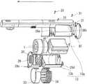
図1に示すように、電気掃除機は、充電台1と本体2とを備える。充電台1は、台座3と支柱4とを備える。凹部5は、支柱4の上面の手前側に形成される。充電端子6は、凹部5に設けられる。本体2は、充電台1に対して着脱自在に設けられる。本体2は、電動送風機7と電池ユニット8と筐体9と集塵容器10と延長管11と吸込口体12とを備える。  As shown in FIG. 1, the vacuum cleaner includes acharging stand 1 and amain body 2. The chargingstand 1 includes apedestal 3 and a support column 4. Therecess 5 is formed on the front side of the upper surface of the support column 4. Thecharging terminal 6 is provided in therecess 5. Themain body 2 is provided detachably with respect to the chargingstand 1. Themain body 2 includes anelectric blower 7, abattery unit 8, ahousing 9, adust collection container 10, anextension pipe 11, and asuction port body 12.

電動送風機7は、図示しないモータとファンとを備える。電池ユニット8は、図1においては図示しない複数の電池8aを備える。電池ユニット8は、電動送風機7よりも重い。  Theelectric blower 7 includes a motor and a fan (not shown). Thebattery unit 8 includes a plurality ofbatteries 8a not shown in FIG. Thebattery unit 8 is heavier than theelectric blower 7.

筐体9は、収容部13と把持部14と操作部15と管部16と凸部17と第1筐体カバー18と第2筐体カバー19とを備える。収容部13は、円筒状に形成される。収容部13は、電動送風機7と電池ユニット8とを収容する。把持部14は、収容部13の手前側に形成される。把持部14は、収容部13の中心軸と同方向に直線状に形成される。操作部15は、把持部14の手前側に設けられる。管部16は、筒状に形成される。管部16は、把持部14の下方において把持部14と一直線上に配置される。凸部17は、管部16の奥側に形成される。第1筐体カバー18は、把持部14の手前側と操作部15の手前側とを覆う。第2筐体カバー19は、管部16の手前側を覆う。  Thehousing 9 includes ahousing portion 13, a grippingportion 14, anoperation portion 15, atube portion 16, aconvex portion 17, afirst housing cover 18, and asecond housing cover 19. Theaccommodating part 13 is formed in a cylindrical shape. Theaccommodating part 13 accommodates theelectric blower 7 and thebattery unit 8. Thegrip portion 14 is formed on the front side of thehousing portion 13. Thegripping part 14 is formed linearly in the same direction as the central axis of thehousing part 13. Theoperation unit 15 is provided on the front side of thegrip unit 14. Thepipe part 16 is formed in a cylindrical shape. Thepipe portion 16 is arranged in a straight line with thegrip portion 14 below thegrip portion 14. Theconvex portion 17 is formed on the back side of thetube portion 16. Thefirst housing cover 18 covers the near side of thegrip part 14 and the near side of theoperation part 15. Thesecond housing cover 19 covers the front side of thepipe portion 16.

集塵容器10は、円筒状に形成される。集塵容器10の外径は、筐体9の収容部13の外径に合わせて形成される。集塵容器10は、筐体9の収容部13の下方に配置される。集塵容器10は、筐体9の凸部17の上方に配置される。集塵容器10は、筐体9の収容部13に対して着脱自在に設けられる。集塵容器10の中心軸は、電動送風機7と筐体9の収容部13との中心軸とほぼ一致する。集塵容器10は、電池ユニット8よりも軽い。延長管11は、筒状に形成される。延長管11は、把持部14と管部16と一直線上に配置される。延長管11の上端部は、管部16の下端部に連結される。延長管11の手前側は、延長管カバー11aに覆われる。吸込口体12は、直方体状に形成される。吸込口体12は、図示しない回転ブラシとブラシモータとを備える。吸込口体12は、幅方向の中央部において延長管11の下端部に連結される。  Thedust collecting container 10 is formed in a cylindrical shape. The outer diameter of thedust collecting container 10 is formed in accordance with the outer diameter of thehousing portion 13 of thehousing 9. Thedust container 10 is disposed below thehousing portion 13 of thehousing 9. Thedust collection container 10 is disposed above theconvex portion 17 of thehousing 9. Thedust container 10 is detachably provided to thehousing part 13 of thehousing 9. The central axis of thedust collecting container 10 substantially coincides with the central axis of theelectric blower 7 and thehousing part 13 of thehousing 9. Thedust collection container 10 is lighter than thebattery unit 8. Theextension tube 11 is formed in a cylindrical shape. Theextension pipe 11 is arranged on the holdingpart 14 and thepipe part 16 in a straight line. The upper end portion of theextension tube 11 is connected to the lower end portion of thetube portion 16. The front side of theextension tube 11 is covered with anextension tube cover 11a. Thesuction inlet 12 is formed in a rectangular parallelepiped shape. Thesuction inlet 12 includes a rotating brush and a brush motor (not shown). Thesuction port body 12 is connected to the lower end portion of theextension pipe 11 at the center in the width direction.

電動送風機7と筐体9の収容部13と集塵容器10との中心軸は、筐体9の把持部14と管部16と延長管11との中心軸に対して平行にずれる。  The central axes of theelectric blower 7, thehousing part 13 of thehousing 9, and thedust collecting container 10 are shifted in parallel to the central axes of thegripping part 14, thepipe part 16, and theextension pipe 11 of thehousing 9.

次に、図2と図3とを用いて、充電台1と本体2との取り付けを説明する。
図2はこの発明の実施の形態1における電気掃除機の斜視図である。図3はこの発明の実施の形態1における電気掃除機の要部の縦断面図である。
Next, the attachment of the chargingstand 1 and themain body 2 will be described with reference to FIGS. 2 and 3.
FIG. 2 is a perspective view of the electric vacuum cleaner according toEmbodiment 1 of the present invention. FIG. 3 is a longitudinal sectional view of a main part of the electric vacuum cleaner according toEmbodiment 1 of the present invention.

図2において、充電台1は、図示しない電源ケーブルを介して外部電源に接続される。充電台1は、外部電源からの電力を利用して空気清浄機として動作する。本体2は、直立した状態で充電台1に取り付けられる。この際、集塵容器10は、支柱4の上方に配置される。吸込口体12は、台座3の手前側に載せられる。本体2は、充電台1に取り付けられることにより充電台1と電気的に接続される。その結果、電池ユニット8の電池8a(図2においては図示せず)は、外部電源からの電力により充電される。  In FIG. 2, the chargingstand 1 is connected to an external power source via a power cable (not shown). The chargingstand 1 operates as an air purifier using electric power from an external power source. Themain body 2 is attached to the chargingstand 1 in an upright state. At this time, thedust container 10 is disposed above the support column 4. Thesuction port body 12 is placed on the front side of thebase 3. Themain body 2 is electrically connected to the chargingstand 1 by being attached to the chargingstand 1. As a result, thebattery 8a (not shown in FIG. 2) of thebattery unit 8 is charged with power from the external power source.

図3に示すように、本体2が充電台1に取り付けられている際、本体2の凸部17は、充電台1の凹部5に挿入される。その結果、本体2は、充電台1に対して適切な位置に配置される。  As shown in FIG. 3, when themain body 2 is attached to the chargingstand 1, theconvex portion 17 of themain body 2 is inserted into theconcave portion 5 of the chargingstand 1. As a result, themain body 2 is disposed at an appropriate position with respect to the chargingstand 1.

次に、図4を用いて、本体2の使用方法を説明する。
図4はこの発明の実施の形態1における電気掃除機の本体の側面図である。
Next, how to use themain body 2 will be described with reference to FIG.
FIG. 4 is a side view of the main body of the electric vacuum cleaner according toEmbodiment 1 of the present invention.

利用者は、把持部14を持って掃除する。この際、吸込口体12は、利用者の手前側において床面と対向する。  The user cleans by holding thegrip portion 14. At this time, thesuction port body 12 faces the floor surface on the front side of the user.

利用者が操作部15を操作すると、電動送風機7のモータは、電池からの電力を用いて回転する。電動送風機7のファンは、モータの回転に追従して回転する。当該ファンの回転により、電動送風機7は、吸気および排気を開始する。当該吸気および排気により、吸引風が本体2の各風路において発生する。  When the user operates theoperation unit 15, the motor of theelectric blower 7 rotates using electric power from the battery. The fan of theelectric blower 7 rotates following the rotation of the motor. Theelectric blower 7 starts intake and exhaust by the rotation of the fan. Suction air is generated in each air passage of themain body 2 by the intake and exhaust.

利用者が操作部15を操作すると、ブラシモータは、電池からの電力を用いて回転する。回転ブラシは、ブラシモータの回転に追従して回転する。  When the user operates theoperation unit 15, the brush motor rotates using electric power from the battery. The rotating brush rotates following the rotation of the brush motor.

当該吸引風により、床面の塵埃は、空気とともに吸込口体12に吸い込まれる。この際、回転ブラシは、床面の塵を掻き込む。その後、含塵空気は、吸込口体12の内部と延長管11の内部と管部16の内部とを通過して集塵容器10に送られる。集塵容器10は、サイクロン分離機能を発揮する。その結果、集塵容器10の内部において、当該含塵空気は旋回する。塵埃は、遠心力により当該含塵空気から分離する。分離された塵埃は、集塵容器10に一時的に溜められる。  Due to the suction air, the dust on the floor surface is sucked into thesuction port body 12 together with the air. At this time, the rotating brush scrubs the dust on the floor. Thereafter, the dust-containing air passes through the inside of thesuction port body 12, the inside of theextension pipe 11, and the inside of thepipe portion 16 and is sent to thedust collecting container 10. Thedust collection container 10 exhibits a cyclone separation function. As a result, the dust-containing air swirls inside thedust collection container 10. Dust is separated from the dust-containing air by centrifugal force. The separated dust is temporarily stored in thedust collecting container 10.

この際、清浄空気は、集塵容器10から排出される。当該清浄空気は、電動送風機7に吸い込まれる。電動送風機7は、当該清浄空気を本体2の外部に排出する。  At this time, the clean air is discharged from thedust collection container 10. The clean air is sucked into theelectric blower 7. Theelectric blower 7 discharges the clean air to the outside of themain body 2.

次に、図5を用いて、集塵容器10を説明する。
図5はこの発明の実施の形態1における電気掃除機の本体の要部の縦断面図である。
Next, thedust container 10 will be described with reference to FIG.
FIG. 5 is a longitudinal sectional view of a main part of the main body of the electric vacuum cleaner according toEmbodiment 1 of the present invention.

図5に示すように、集塵容器10は、流入管20と旋回室21と0次集塵室22と1次集塵室23と0次開口24と1次開口25と排出管26とフィルタ27とを備える。  As shown in FIG. 5, thedust collection container 10 includes aninflow pipe 20, aswirl chamber 21, a zero-orderdust collection chamber 22, a primarydust collection chamber 23, a zero-order opening 24, aprimary opening 25, adischarge pipe 26, and a filter. 27.

流入管20の一端部は、筐体9の管部16の上端部に連結される。旋回室21は、円筒部21aと円錐部21bとを備える。円筒部21aの上部は、流入管20の他端部に連結される。円錐部21bの上部は、円筒部21aの下部に連結される。0次集塵室22は、旋回室21を囲む。1次集塵室23は、円錐部21bの下方に設けられる。1次集塵室23は、0次集塵室22の内側に設けられる。0次開口24は、円筒部21aの側壁に形成される。1次開口25は、円錐部21bの下端部に形成される。排出管26は、旋回室21の内部に設けられる。フィルタ27は、排出管26の上部に設けられる。  One end of theinflow pipe 20 is connected to the upper end of thepipe part 16 of thehousing 9. Theswirl chamber 21 includes acylindrical portion 21a and aconical portion 21b. The upper part of thecylindrical part 21 a is connected to the other end part of theinflow pipe 20. The upper part of theconical part 21b is connected to the lower part of thecylindrical part 21a. The zero-orderdust collection chamber 22 surrounds theswirl chamber 21. The primarydust collection chamber 23 is provided below theconical portion 21b. The primarydust collection chamber 23 is provided inside the zero-orderdust collection chamber 22. The zero-order opening 24 is formed on the side wall of thecylindrical portion 21a. Theprimary opening 25 is formed in the lower end part of thecone part 21b. Thedischarge pipe 26 is provided inside theswirl chamber 21. Thefilter 27 is provided on the upper part of thedischarge pipe 26.

集塵容器10において、含塵空気は、流入管20の一端部から流入する。当該含塵空気は、流入管20の内部空間を流入管20の軸方向に直進する。当該含塵空気は、円筒部21aの内部に流入する。当該含塵空気は、円筒部21aの内周面に沿って予め設定された方向に旋回する旋回気流となる。当該旋回気流は、強制渦領域と自由渦領域とを形成する。強制渦領域は、当該旋回気流の軸線近傍に形成される。自由渦領域は、強制渦領域の外側に形成される。当該旋回気流は、経路構造と重力とにより下向きに流れる。  In thedust collection container 10, the dust-containing air flows from one end of theinflow pipe 20. The dust-containing air travels straight through the inner space of theinflow pipe 20 in the axial direction of theinflow pipe 20. The dust-containing air flows into thecylindrical portion 21a. The dust-containing air becomes a swirling airflow that swirls in a preset direction along the inner peripheral surface of thecylindrical portion 21a. The swirling airflow forms a forced vortex region and a free vortex region. The forced vortex region is formed near the axis of the swirling airflow. The free vortex region is formed outside the forced vortex region. The swirling airflow flows downward due to the path structure and gravity.

当該旋回気流において、繊維塵埃、毛髪等の比較的嵩の大きな塵埃αは、遠心力により円筒部21aの内周面に押し付けられながら下方に進む。当該塵埃αは、0次開口24の高さに達した際に当該旋回気流から分離される。当該塵埃αは、0次開口24を通過する。当該塵埃αは、0次集塵室22に送られる。  In the swirling airflow, relatively bulky dust α such as fiber dust and hair advances downward while being pressed against the inner peripheral surface of thecylindrical portion 21a by centrifugal force. The dust α is separated from the swirling airflow when the height of the zero-order opening 24 is reached. The dust α passes through the zero-order opening 24. The dust α is sent to the zero-orderdust collection chamber 22.

当該旋回気流において、砂塵埃、細かな繊維塵埃等の比較的嵩の小さな塵埃βは、0次開口24から0次集塵室22に進入しない。当該塵埃βは、遠心力により円錐部21bの内周面に押し付けられながら下方に進む。当該塵埃βは、1次開口25を通過する。当該塵埃βは、1次集塵室23に落下することにより捕捉される。  In the swirling airflow, dust β having a relatively small volume, such as sand dust and fine fiber dust, does not enter the 0th-orderdust collection chamber 22 through the 0th-order opening 24. The dust β proceeds downward while being pressed against the inner peripheral surface of theconical portion 21b by centrifugal force. The dust β passes through theprimary opening 25. The dust β is captured by dropping into the primarydust collection chamber 23.

旋回気流は、旋回室21の最下部に達する。当該旋回気流は、進行方向を上向きに変えて上昇気流となる。当該上昇気流は、旋回室21の中心軸に沿って上昇する。当該上昇気流は、塵埃αおよび塵埃βを含まない清浄空気となる。当該清浄空気は、排出管26とフィルタ27とを通過して電動送風機7に吸い込まれる。電動送風機7は、当該清浄空気を本体2の外部に排出する。  The swirling airflow reaches the lowermost part of the swirlingchamber 21. The swirling airflow is changed to an upward flow by changing the traveling direction upward. The updraft rises along the central axis of theswirl chamber 21. The updraft becomes clean air that does not contain dust α and dust β. The clean air passes through thedischarge pipe 26 and thefilter 27 and is sucked into theelectric blower 7. Theelectric blower 7 discharges the clean air to the outside of themain body 2.

次に、図6を用いて、含塵空気の流入方法を説明する。
図6はこの発明の実施の形態1における電気掃除機の本体の要部の横断面図である。
Next, a method for introducing dust-containing air will be described with reference to FIG.
FIG. 6 is a cross-sectional view of the main part of the main body of the electric vacuum cleaner according toEmbodiment 1 of the present invention.

図6に示すように、管部16は、円筒部21aの接線の方向から円筒部21aに向かう。管部16は、流入管20につながる。流入管20は、円筒部21aの接線の方向から円筒部21aにつながる。その結果、矢印で示すように、含塵空気は、円筒部21aの内周面に沿うように円筒部21aの内周面の接線の方向から滑らかに流入する。  As shown in FIG. 6, thepipe part 16 goes from the tangential direction of thecylindrical part 21a toward thecylindrical part 21a. Thepipe portion 16 is connected to theinflow pipe 20. Theinflow pipe 20 is connected to thecylindrical portion 21a from the tangential direction of thecylindrical portion 21a. As a result, as indicated by the arrows, the dust-containing air smoothly flows in from the tangential direction of the inner peripheral surface of thecylindrical portion 21a along the inner peripheral surface of thecylindrical portion 21a.

次に、図7から図9を用いて、筐体9の収容部13を説明する。
図7から図9はこの発明の実施の形態1における電気掃除機の本体の要部の分解斜視図である。図7から図9においては、矢印の方向が電気掃除機の下側である。
Next, theaccommodating part 13 of the housing | casing 9 is demonstrated using FIGS.
7 to 9 are exploded perspective views of main parts of the main body of the electric vacuum cleaner according toEmbodiment 1 of the present invention. 7 to 9, the direction of the arrow is the lower side of the vacuum cleaner.

図7に示すように、電動送風機7と電池ユニット8とは、収容部13の中心軸に沿って一直線上に配置される。電池ユニット8は、電動送風機7の排気側に配置される。電池ユニット8は、電動送風機7よりも把持部14の側に配置される。  As shown in FIG. 7, theelectric blower 7 and thebattery unit 8 are arranged on a straight line along the central axis of thehousing portion 13. Thebattery unit 8 is disposed on the exhaust side of theelectric blower 7. Thebattery unit 8 is disposed closer to thegrip portion 14 than theelectric blower 7.

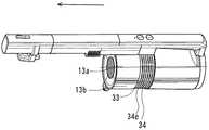
収容部13は、第1本体ケース13aと第2本体ケース13bとを備える。第1本体ケース13aと第2本体ケース13bとの断面は、ほぼ半円状となる。第1本体ケース13aは、電動送風機7と電池ユニット8との一側に配置される。第2本体ケース13bは、電動送風機7と電池ユニット8との他側に配置される。  Theaccommodating portion 13 includes a firstmain body case 13a and a secondmain body case 13b. The cross sections of the firstmain body case 13a and the secondmain body case 13b are substantially semicircular. The firstmain body case 13 a is disposed on one side of theelectric blower 7 and thebattery unit 8. The secondmain body case 13 b is disposed on the other side of theelectric blower 7 and thebattery unit 8.

凹部28aは、電動送風機7と電池ユニット8とが並んだ方向において第1本体ケース13aの外周の中央部に形成される。凹部28bは、電動送風機7と電池ユニット8とが並んだ方向において第1本体ケース13aの外周の上側に形成される。凹部28cは、電動送風機7と電池ユニット8とが並んだ方向において第2本体ケース13bの外周の中央部に形成される。凹部28dは、電動送風機7と電池ユニット8とが並んだ方向において第2本体ケース13bの外周の上側に形成される。  Therecess 28a is formed at the center of the outer periphery of the firstmain body case 13a in the direction in which theelectric blower 7 and thebattery unit 8 are arranged. The recess 28b is formed on the upper side of the outer periphery of the firstmain body case 13a in the direction in which theelectric blower 7 and thebattery unit 8 are arranged. Therecess 28c is formed at the center of the outer periphery of the secondmain body case 13b in the direction in which theelectric blower 7 and thebattery unit 8 are arranged. Therecess 28d is formed on the upper side of the outer periphery of the secondmain body case 13b in the direction in which theelectric blower 7 and thebattery unit 8 are arranged.

吸気口29は、第2本体ケース13bの下部に形成される。排気口30は、第2本体ケース13bの凹部28cに形成される。排気口30は、第1本体ケース13aの凹部28aに形成されない。  Theintake port 29 is formed in the lower part of the secondmain body case 13b. Theexhaust port 30 is formed in therecess 28c of the secondmain body case 13b. Theexhaust port 30 is not formed in therecess 28a of the firstmain body case 13a.

図8に示すように、第1本体ケース13aと第2本体ケース13bとは、複数の締結体31によって締結される。例えば、複数の締結体31は、ネジからなる。例えば、締結体31は、収容部13の両側において第1本体ケース13aの凹部28aと第2本体ケース13bの凹部28cとを締結する。図示しないが、締結体31は、収容部13の両側において第1本体ケース13aの凹部28bと第2本体ケース13bの凹部28dとを締結する。この際、第1本体ケース13aの凹部28bと第2本体ケース13bの凹部28dとは、トップカバー32に覆われる。その結果、締結体31は、本体2の外部から遮蔽される。  As shown in FIG. 8, the firstmain body case 13 a and the secondmain body case 13 b are fastened by a plurality offastening bodies 31. For example, the plurality offastening bodies 31 are made of screws. For example, thefastening body 31 fastens theconcave portion 28 a of the firstmain body case 13 a and theconcave portion 28 c of the secondmain body case 13 b on both sides of thehousing portion 13. Although not shown, thefastening body 31 fastens the concave portion 28b of the firstmain body case 13a and theconcave portion 28d of the secondmain body case 13b on both sides of thehousing portion 13. At this time, the concave portion 28b of the firstmain body case 13a and theconcave portion 28d of the secondmain body case 13b are covered with thetop cover 32. As a result, thefastening body 31 is shielded from the outside of themain body 2.

図9において、消音材33は、目の細かい材料で形成される。消音材33は、第1本体ケース13aの凹部28aと第2本体ケース13bの凹部28cとをほぼ全面的に外側から覆う。排気口カバー34は、複数の開口部34eを備える。各開口部34eの開口面積は、消音材33の目の面積よりも小さい。排気口カバー34は、消音材33をほぼ全面的に外側から覆う。その結果、締結体31は、本体2の外部から遮蔽される。  In FIG. 9, thesilencer 33 is formed of a fine material. Thesilencer 33 covers theconcave portion 28a of the firstmain body case 13a and theconcave portion 28c of the secondmain body case 13b almost entirely from the outside. Theexhaust port cover 34 includes a plurality ofopenings 34e. The opening area of each opening 34 e is smaller than the area of the eyes of thesound deadening material 33. The exhaust port cover 34 covers thesound deadening material 33 almost entirely from the outside. As a result, thefastening body 31 is shielded from the outside of themain body 2.

次に、図10と図11とを用いて、排気口カバー34の取り付けを説明する。
図10はこの発明の実施の形態1における電気掃除機の本体の要部の正面図である。図11は図10のA−A線における断面図である。
Next, the attachment of theexhaust port cover 34 will be described with reference to FIGS. 10 and 11.
FIG. 10 is a front view of the main part of the main body of the electric vacuum cleaner according toEmbodiment 1 of the present invention. 11 is a cross-sectional view taken along line AA in FIG.

図10に示すように、消音材33と排気口カバー34とが収容部13に適切に取り付けられると、排気口カバー34の外径は、収容部13の外径とほぼ一致する。  As shown in FIG. 10, when thesilencer 33 and theexhaust port cover 34 are appropriately attached to thehousing part 13, the outer diameter of the exhaust port cover 34 substantially matches the outer diameter of thehousing part 13.

図11に示すように、第1本体ケース13aは、凹部35を備える。凹部35は、第1本体ケース13aの内部において把持部14の側に形成される。排気口カバー34の一端部は、凹部35の一側に収まる。排気口カバー34の他端部は、凹部35の他側に収まる。その結果、排気口カバー34は、収容部13に確実に保持される。  As shown in FIG. 11, the firstmain body case 13 a includes arecess 35. Therecess 35 is formed on thegrip 14 side in the firstmain body case 13a. One end of the exhaust port cover 34 fits on one side of therecess 35. The other end of the exhaust port cover 34 fits on the other side of therecess 35. As a result, theexhaust port cover 34 is securely held in thehousing portion 13.

次に、図12から図14を用いて、排気口カバー34を説明する。
図12はこの発明の実施の形態1における電気掃除機の排気口カバーの斜視図である。図13はこの発明の実施の形態1における電気掃除機の排気口カバーの側面図である。図14は図13のB−B線における断面図である。
Next, theexhaust port cover 34 will be described with reference to FIGS.
FIG. 12 is a perspective view of the exhaust port cover of the electric vacuum cleaner according toEmbodiment 1 of the present invention. FIG. 13 is a side view of the exhaust port cover of the electric vacuum cleaner according toEmbodiment 1 of the present invention. 14 is a cross-sectional view taken along line BB in FIG.

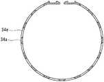
図12に示すように、排気口カバー34は、遮蔽部34aと一対の変形部34bと一対の突起部34cと複数の壁部34dとを備える。  As shown in FIG. 12, theexhaust port cover 34 includes a shieldingpart 34a, a pair of deformingparts 34b, a pair of projecting parts 34c, and a plurality ofwall parts 34d.

遮蔽部34aは、C字状に形成される。遮蔽部34aの両端部は、互いに対向する。各変形部34bは、遮蔽部34aの両端部の各々に連結される。各変形部34bは、遮蔽部34aの外面よりも遮蔽部34aの中心軸の側へ凹む。各突起部34cは、各変形部34bの先端部に連結される。各突起部34cは、各変形部34bから遮蔽部34aの外側に向けて突き出す。各壁部34dは、各変形部34bの両側に並んだ状態で遮蔽部34aの各端部に連結される。各壁部34dは、遮蔽部34aから遮蔽部34aの外側に向けて突き出す。  The shieldingpart 34a is formed in a C shape. Both end portions of the shieldingportion 34a face each other. Each deformingportion 34b is connected to each of both end portions of the shieldingportion 34a. Eachdeformation portion 34b is recessed toward the central axis of the shieldingportion 34a from the outer surface of the shieldingportion 34a. Each protrusion 34c is connected to the tip of eachdeformable portion 34b. Each protrusion 34c protrudes from eachdeformation portion 34b toward the outside of the shieldingportion 34a. Eachwall part 34d is connected with each edge part of the shieldingpart 34a in the state arranged in the both sides of each deformation |transformation part 34b. Eachwall portion 34d protrudes from the shieldingportion 34a toward the outside of the shieldingportion 34a.

排気口カバー34が収容部13に適切に取り付けられる際、各突起部34cは、第1本体ケース13aの凹部35の側方に形成された開口に挿入される。この際、各変形部34bは、変形する。その後、各突起部34cが第1本体ケース13aの凹部35に収まると、各変形部34bは、変形から解放される。この際、各壁部34dは、第1本体ケース13aの開口を外側から遮蔽する。  When theexhaust port cover 34 is appropriately attached to thehousing portion 13, each projection 34c is inserted into an opening formed on the side of theconcave portion 35 of the firstmain body case 13a. At this time, each deformingportion 34b is deformed. Thereafter, when the protrusions 34c are received in therecesses 35 of the firstmain body case 13a, thedeformation portions 34b are released from the deformation. At this time, eachwall portion 34d shields the opening of the firstmain body case 13a from the outside.

図12から図14に示すように、遮蔽部34aの外観は、均一である。例えば、遮蔽部34aは、複数の開口部34eを備える。複数の開口部34eは、遮蔽部34aの全体に均一に形成される。複数の開口部34eは、排気口カバー34の中心軸の方向と排気口カバー34の外周に沿った方向に規則正しく配置される。  As shown in FIGS. 12 to 14, the appearance of the shieldingpart 34 a is uniform. For example, the shieldingpart 34a includes a plurality ofopenings 34e. The plurality ofopenings 34e are formed uniformly over theentire shielding part 34a. The plurality ofopenings 34 e are regularly arranged in the direction of the central axis of theexhaust port cover 34 and the direction along the outer periphery of theexhaust port cover 34.

次に、図15と図16とを用いて、電池ユニット8を説明する。
図15はこの発明の実施の形態1における電気掃除機の電池ユニットの分解斜視図である。図16はこの発明の実施の形態1における電気掃除機の電池ユニットの斜視断面図である。
Next, thebattery unit 8 will be described with reference to FIGS. 15 and 16.
FIG. 15 is an exploded perspective view of the battery unit of the electric vacuum cleaner according toEmbodiment 1 of the present invention. FIG. 16 is a perspective cross-sectional view of the battery unit of the electric vacuum cleaner according toEmbodiment 1 of the present invention.

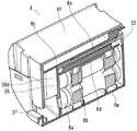
図15に示すように、電池ユニット8は、複数の電池8aと電池制御基板8bと本体制御基板8cと保持体8dと仕切体8eと第1電池ケース8fと第2電池ケース8gとを備える。  As shown in FIG. 15, thebattery unit 8 includes a plurality ofbatteries 8a, abattery control board 8b, a mainbody control board 8c, a holdingbody 8d, apartition 8e, afirst battery case 8f, and asecond battery case 8g.

各電池8aは、蓄電池からなる。例えば、各電池8aは、リチウムイオン電池からなる。電池制御基板8bは、電池8aの出力電圧等を制御する素子を搭載する。本体制御基板8cは、電動送風機7の動作を制御する素子を搭載する。保持部は、樹脂で形成される。保持体8dは、複数の保持部を備える。保持部の数は、電池8aの数と同じである。仕切体8eは、樹脂で形成される。仕切体8eは、凸部36を備える。第1電池ケース8fは、樹脂で形成される。第2電池ケース8gは、樹脂で形成される。第2電池ケース8gは、一対の壁部37を備える。  Eachbattery 8a consists of a storage battery. For example, eachbattery 8a is a lithium ion battery. Thebattery control board 8b is equipped with an element for controlling the output voltage of thebattery 8a. The mainbody control board 8c is equipped with an element for controlling the operation of theelectric blower 7. The holding part is made of resin. The holdingbody 8d includes a plurality of holding units. The number of holding parts is the same as the number ofbatteries 8a. Thepartition 8e is made of resin. Thepartition 8e includes aconvex portion 36. Thefirst battery case 8f is made of resin. Thesecond battery case 8g is made of resin. Thesecond battery case 8g includes a pair ofwall portions 37.

本体制御基板8cは、第1コネクタ38aと第2コネクタ38bと第3コネクタ38cと第4コネクタ38dと第5コネクタ38eとを備える。第1コネクタ38aと第2コネクタ38bとは、本体制御基板8cの表面の一側に設けられる。第3コネクタ38cと第4コネクタ38dと第5コネクタ38eとは、本体制御基板8cの裏面の一側に設けられる。  The mainbody control board 8c includes afirst connector 38a, asecond connector 38b, athird connector 38c, afourth connector 38d, and afifth connector 38e. Thefirst connector 38a and thesecond connector 38b are provided on one side of the surface of the mainbody control board 8c. Thethird connector 38c, thefourth connector 38d, and thefifth connector 38e are provided on one side of the back surface of the mainbody control board 8c.

第1コネクタ38aは、本体制御基板8cと操作部15とを電気的に接続する際に用いられる。第2コネクタ38bは、本体制御基板8cと充電端子6とを電気的に接続する際に用いられる。第2コネクタ38bは、本体制御基板8cとブラシモータとを電気的に接続する際に用いられる。第3コネクタ38cと第4コネクタ38dとは、本体制御基板8cと電動送風機7のモータとを電気的に接続する際に用いられる。第5コネクタ38eは、電動送風機7に取り付けられたサーミスタと電気的に接続する際に用いられる。  Thefirst connector 38a is used when the mainbody control board 8c and theoperation unit 15 are electrically connected. Thesecond connector 38b is used when the mainbody control board 8c and the chargingterminal 6 are electrically connected. Thesecond connector 38b is used when the mainbody control board 8c and the brush motor are electrically connected. Thethird connector 38c and thefourth connector 38d are used when the mainbody control board 8c and the motor of theelectric blower 7 are electrically connected. Thefifth connector 38e is used when electrically connecting to the thermistor attached to theelectric blower 7.

図16に示すように、保持体8dは、電池8aと電池制御基板8bとの間に設けられる。保持体8dの各保持部は、各電池8aを保持する。仕切体8eは、電池制御基板8bと本体制御基板8cとの間に配置される。第1電池ケース8fは、電池8aと制御基板と本体制御基板8cとが並んだ方向の一側に配置される。第2電池ケース8gは、電池8aと制御基板と本体制御基板8cとが並んだ方向の他側に配置される。第1電池ケース8fと第2電池ケース8gとは、電池8aと電池制御基板8bと本体制御基板8cと保持体8dと仕切体8eとを覆う。  As shown in FIG. 16, the holdingbody 8d is provided between thebattery 8a and thebattery control board 8b. Each holding portion of the holdingbody 8d holds eachbattery 8a. Thepartition 8e is disposed between thebattery control board 8b and the mainbody control board 8c. Thefirst battery case 8f is disposed on one side of the direction in which thebattery 8a, the control board, and the mainbody control board 8c are arranged. Thesecond battery case 8g is disposed on the other side in the direction in which thebattery 8a, the control board, and the mainbody control board 8c are arranged. Thefirst battery case 8f and thesecond battery case 8g cover thebattery 8a, thebattery control board 8b, the mainbody control board 8c, the holdingbody 8d, and thepartitioning body 8e.

電池ユニット8において、仕切体8eの凸部36は、第2電池ケース8gの一対の壁部37の間に嵌め合わされる。その結果、第3コネクタ38cと第4コネクタ38dと第5コネクタ38eとの側の空間と複数の電池8aの側の空間とは、仕切体8eの凸部36と第2電池ケース8gの一対の壁とにより区切られる。  In thebattery unit 8, theconvex part 36 of thepartition 8e is fitted between the pair ofwall parts 37 of thesecond battery case 8g. As a result, the space on the side of thethird connector 38c, thefourth connector 38d, and thefifth connector 38e and the space on the side of the plurality ofbatteries 8a are a pair of theconvex portion 36 of thepartition 8e and thesecond battery case 8g. Separated by walls.

次に、図17を用いて、本体2の配線を説明する。
図17はこの発明の実施の形態1における電気掃除機の本体の要部の縦断面図である。図17においては、矢印方向が手前側である。
Next, the wiring of themain body 2 will be described with reference to FIG.
FIG. 17 is a longitudinal sectional view of a main part of the main body of the electric vacuum cleaner according toEmbodiment 1 of the present invention. In FIG. 17, the arrow direction is the front side.

図17に示すように、電池ユニット8が収容部13に適切に収容されると、電池8aは、電池制御基板8bと本体制御基板8cとよりも把持部14から離れる。  As shown in FIG. 17, when thebattery unit 8 is appropriately accommodated in theaccommodating portion 13, thebattery 8 a is further away from thegrip portion 14 than thebattery control board 8 b and the mainbody control board 8 c.

操作部リード線39は、本体制御基板8cにおける電動送風機7の側とは反対側と操作部15とを電気的に接続する。具体的には、操作部リード線39は、トップカバー32の内側と把持部14の手前側とに沿って配線される。操作部リード線39は、トップカバー32と第1筐体カバー18とに覆われる。操作部リード線39の一側は、操作部15に接続される。操作部リード線39の他側は、第1コネクタ38aに接続される。  The operationpart lead wire 39 electrically connects theoperation part 15 and the side opposite to theelectric blower 7 side in the mainbody control board 8c. Specifically, the operationpart lead wire 39 is wired along the inside of thetop cover 32 and the front side of thegrip part 14. The operationunit lead wire 39 is covered with thetop cover 32 and thefirst housing cover 18. One side of the operationunit lead wire 39 is connected to theoperation unit 15. The other side of the operationunit lead wire 39 is connected to thefirst connector 38a.

充電端子リード線40は、本体制御基板8cにおける電動送風機7の側とは反対側とブラシモータとを電気的に接続する。具体的には、充電端子リード線40は、トップカバー32の内側と把持部14の手前側と操作部15の手前側と管部16の手前側と延長管11の手前側とに沿って配線される。充電端子リード線40は、トップカバー32と第1筐体カバー18に覆われる。充電端子リード線40の一側は、操作部15に接続される。充電端子リード線40の他側は、第2コネクタ38bに接続される。  The chargingterminal lead wire 40 electrically connects the brush motor to the opposite side of the mainbody control board 8c to theelectric blower 7 side. Specifically, the chargingterminal lead 40 is wired along the inside of thetop cover 32, the near side of thegripping part 14, the near side of theoperation part 15, the near side of thepipe part 16, and the near side of theextension pipe 11. Is done. The chargingterminal lead wire 40 is covered with thetop cover 32 and thefirst housing cover 18. One side of the chargingterminal lead wire 40 is connected to theoperation unit 15. The other side of the chargingterminal lead 40 is connected to thesecond connector 38b.

ブラシモータリード線41は、本体制御基板8cにおける電動送風機7の側とは反対側とブラシモータとを電気的に接続する。具体的には、ブラシモータリード線41は、トップカバー32の内側と把持部14の手前側と操作部15の手前側と管部16の手前側と延長管11の手前側とに沿って配線される。ブラシモータリード線41は、トップカバー32と第1筐体カバー18と第2筐体カバー19とに覆われる。図示しないが、ブラシモータリード線41は、延長管カバー11aにも覆われる。ブラシモータリード線41の一側は、操作部15に接続される。ブラシモータリード線41の他側は、第2コネクタ38bに接続される。  The brushmotor lead wire 41 electrically connects the brush motor to the side opposite to theelectric blower 7 side in the mainbody control board 8c. Specifically, the brushmotor lead wire 41 is wired along the inside of thetop cover 32, the near side of thegripping part 14, the near side of theoperation part 15, the near side of thepipe part 16, and the near side of theextension pipe 11. Is done. The brushmotor lead wire 41 is covered with thetop cover 32, thefirst housing cover 18, and thesecond housing cover 19. Although not shown, the brushmotor lead wire 41 is also covered by theextension tube cover 11a. One side of the brushmotor lead wire 41 is connected to theoperation unit 15. The other side of thebrush motor lead 41 is connected to thesecond connector 38b.

第1電動送風機リード線42と第2電動送風機リード線43とは、本体制御基板8cにおける電動送風機7の側と電動送風機7のモータとを電気的に接続する。具体的には、第1電動送風機リード線42の一側は、電動送風機7のモータの入力端子に接続される。第1電動送風機リード線42の他側は、第3コネクタ38cに接続される。第2電動送風機リード線43の一側は、電動送風機7のモータの入力端子に接続される。第2電動送風機リード線43の他側は、第4コネクタ38dに接続される。  The first electricblower lead wire 42 and the second electricblower lead wire 43 electrically connect theelectric blower 7 side and the motor of theelectric blower 7 in the mainbody control board 8c. Specifically, one side of the first electricblower lead wire 42 is connected to the input terminal of the motor of theelectric blower 7. The other side of the first electricblower lead wire 42 is connected to thethird connector 38c. One side of the second electricblower lead wire 43 is connected to the input terminal of the motor of theelectric blower 7. The other side of the second electricblower lead wire 43 is connected to thefourth connector 38d.

サーミスタリード線44は、本体制御基板8cにおける電動送風機7の側と電動送風機7に設けられたサーミスタとを電気的に接続する。具体的には、サーミスタリード線44の一側は、サーミスタに接続される。サーミスタリード線44の他側は、第5コネクタ38eに接続される。  Thethermistor lead wire 44 electrically connects theelectric blower 7 side of the mainbody control board 8c and the thermistor provided in theelectric blower 7. Specifically, one side of thethermistor lead wire 44 is connected to the thermistor. The other side of thethermistor lead wire 44 is connected to thefifth connector 38e.

次に、図18から図20を用いて、筐体9から集塵容器10を取り外す方法を説明する。
図18から図20はこの発明の実施の形態1における電気掃除機の本体の要部の縦断面図である。
Next, a method for removing thedust collecting container 10 from thehousing 9 will be described with reference to FIGS.
18 to 20 are longitudinal sectional views of main parts of the main body of the electric vacuum cleaner according toEmbodiment 1 of the present invention.

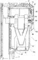
図18に示すように、筐体9は、凸部45を備える。凸部45は、凸部17の上方に設けられる。集塵容器10は、集塵カップ10aと操作体10bを備える。集塵カップ10aは、集塵容器10の下部に設けられる。集塵カップ10aは、円筒状に形成される。集塵カップ10aは、底部を備える。集塵カップ10aは、凹部46を備える。凹部46は、集塵カップ10aの底部の手前側に形成される。集塵カップ10aは、0次集塵室22を形成する。操作体10bは、集塵容器10の奥側に設けられる。操作体10bは、レバー47とラッチ48と第1弾性体49と第2弾性体50とを備える。  As shown in FIG. 18, thehousing 9 includes aconvex portion 45. Theconvex portion 45 is provided above theconvex portion 17. Thedust collection container 10 includes adust collection cup 10a and anoperation body 10b. Thedust collection cup 10 a is provided at the lower part of thedust collection container 10. Thedust collection cup 10a is formed in a cylindrical shape. Thedust collection cup 10a has a bottom. Thedust collection cup 10 a includes arecess 46. Therecess 46 is formed on the near side of the bottom of thedust collection cup 10a. Thedust collection cup 10 a forms a zero-orderdust collection chamber 22. Theoperation body 10b is provided on the back side of thedust container 10. The operatingbody 10b includes alever 47, alatch 48, a firstelastic body 49, and a secondelastic body 50.

集塵容器10が筐体9に適切に取り付けられると、筐体9の凸部45は、集塵カップ10aの凹部46に嵌る。操作体10bは、第1位置に配置される。この際、レバー47の上部は、筐体9の凹部13cに挿入される。ラッチ48は、レバー47の下方に配置される。ラッチ48の下部は、集塵カップ10aの一部と噛み合う。第1弾性体49は、上向きの荷重をレバー47の上部に与える。第2弾性体50は、集塵容器10の外側へ向いた水平方向の荷重をラッチ48の上部に与える。その結果、集塵容器10は、筐体9との連結を維持する。集塵カップ10aは、集塵容器10の他の部分との連結を維持する。  When thedust container 10 is properly attached to thehousing 9, theconvex portion 45 of thehousing 9 fits into theconcave portion 46 of thedust collecting cup 10a. The operatingbody 10b is disposed at the first position. At this time, the upper portion of thelever 47 is inserted into therecess 13 c of thehousing 9. Thelatch 48 is disposed below thelever 47. The lower part of thelatch 48 meshes with a part of thedust collection cup 10a. The firstelastic body 49 applies an upward load to the upper portion of thelever 47. The secondelastic body 50 applies a horizontal load directed to the outside of thedust collecting container 10 to the upper portion of thelatch 48. As a result, thedust collecting container 10 maintains the connection with thehousing 9. Thedust collection cup 10a maintains the connection with the other part of thedust collection container 10.

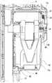
図19に示すように、使用者が操作位置となる凹部47bに指をかけて、下方に押すことでレバー47が第1弾性体49からの荷重よりも大きな荷重で下げられると、操作体10bは、第2位置に配置される。この際、レバー47の上部は、筐体9の凹部13cから外れる。その結果、集塵容器10は、筐体9との連結から解放される。この際、集塵カップ10aは、集塵容器10の他の部分との連結を維持する。  As shown in FIG. 19, when thelever 47 is lowered with a load larger than the load from the firstelastic body 49 by placing a finger on theconcave portion 47b serving as the operation position and pushing it downward, theoperation body 10b Is arranged in the second position. At this time, the upper portion of thelever 47 is detached from theconcave portion 13 c of thehousing 9. As a result, thedust container 10 is released from the connection with thehousing 9. At this time, thedust collection cup 10 a maintains the connection with the other part of thedust collection container 10.

図20に示すように、操作体10bが第2位置に配置された状態において集塵容器10の上部を奥側に倒すと、集塵容器10は、筐体9から取り外される。この際、集塵カップ10aは、集塵容器10の他の部分との連結を維持する。  As shown in FIG. 20, when the upper part of thedust collection container 10 is tilted to the back side in a state where theoperation body 10 b is disposed at the second position, thedust collection container 10 is removed from thehousing 9. At this time, thedust collection cup 10 a maintains the connection with the other part of thedust collection container 10.

次に、図21を用いて、集塵容器10から集塵カップ10aを取り外す方法を説明する。
図21はこの発明の実施の形態1における電気掃除機の本体の要部の縦断面図である。
Next, a method for removing thedust collection cup 10a from thedust collection container 10 will be described with reference to FIG.
FIG. 21 is a longitudinal sectional view of the main part of the main body of the electric vacuum cleaner according toEmbodiment 1 of the present invention.

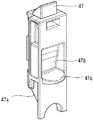
図21に示すように、レバー47が第1弾性からの荷重および第2弾性体50からの荷重に対応した荷重を合計した荷重よりも大きな荷重でさらに下げられると、操作体10bは、第3位置に配置される。この際の操作方向は、操作体10bが第1位置から第2位置まで操作される方向と一致する。この際、ラッチ48の下部は、集塵容器10の外側に開く。その結果、ラッチ48の下部は、集塵カップ10aの一部との噛み合いから解放される。この状態で、集塵カップ10aが下げられると、集塵カップ10aは、集塵容器10から取り外される。この状態で、集塵カップ10aを上下反転させると、塵埃αおよび塵埃βが廃棄される。  As shown in FIG. 21, when thelever 47 is further lowered by a load larger than the total load of the load from the first elasticity and the load from the secondelastic body 50, the operatingbody 10 b is Placed in position. The operation direction at this time coincides with the direction in which theoperating body 10b is operated from the first position to the second position. At this time, the lower portion of thelatch 48 opens to the outside of thedust collecting container 10. As a result, the lower portion of thelatch 48 is released from meshing with a part of thedust collection cup 10a. When thedust collection cup 10a is lowered in this state, thedust collection cup 10a is removed from thedust collection container 10. In this state, when thedust collection cup 10a is turned upside down, the dust α and the dust β are discarded.

次に、図22から図24を用いて、レバー47とラッチ48との動作を説明する。
図22から図24はこの発明の実施の形態1における電気掃除機のレバーとラッチとの側面図である。
Next, the operation of thelever 47 and thelatch 48 will be described with reference to FIGS.
22 to 24 are side views of the lever and the latch of the electric vacuum cleaner according toEmbodiment 1 of the present invention.

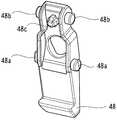
図22から図24に示すように、レバー47は、ガイド部47aを備える。ガイド部47aは、レバー47の下部に形成される。ガイド部47aは、垂直部と傾斜部とを備える。ラッチ48は、回転軸48aと接触部48bと備える。回転軸48aは、円柱状に形成される。回転軸48aは、ラッチ48の上下方向における中央部の両側に形成される。接触部48bは、円柱状に形成される。接触部48bは、ラッチ48の上部の両側に形成される。  As shown in FIGS. 22 to 24, thelever 47 includes aguide portion 47a. Theguide portion 47 a is formed below thelever 47. Theguide part 47a includes a vertical part and an inclined part. Thelatch 48 includes arotating shaft 48a and acontact portion 48b. Therotating shaft 48a is formed in a cylindrical shape. Therotation shaft 48 a is formed on both sides of the central portion in the vertical direction of thelatch 48. Thecontact part 48b is formed in a cylindrical shape. Thecontact portions 48 b are formed on both sides of the upper portion of thelatch 48.

図22に示すように、操作体10bが第1位置に配置されると、ラッチ48の接触部48bは、レバー47の垂直部の下部に接触する。図23に示すように、操作体10bが第2位置まで下げられると、ラッチ48の操作部15は、レバー47の垂直部の上部に接触する。図24に示すように、操作体10bが第3位置まで下げられると、ラッチ48の操作部15は、レバー47の傾斜部に移動する。この際、ラッチ48は、回転軸48aを中心にして回転する。  As shown in FIG. 22, when the operatingbody 10 b is disposed at the first position, thecontact portion 48 b of thelatch 48 contacts the lower portion of the vertical portion of thelever 47. As shown in FIG. 23, when the operatingbody 10 b is lowered to the second position, the operatingportion 15 of thelatch 48 contacts the upper portion of the vertical portion of thelever 47. As shown in FIG. 24, when the operatingbody 10 b is lowered to the third position, the operatingportion 15 of thelatch 48 moves to the inclined portion of thelever 47. At this time, thelatch 48 rotates around therotation shaft 48a.

次に、図25を用いて、レバー47の詳細を説明する。
図25はこの発明の実施の形態1における電気掃除機のレバーの斜視図である。
Next, the details of thelever 47 will be described with reference to FIG.
FIG. 25 is a perspective view of the lever of the electric vacuum cleaner according toEmbodiment 1 of the present invention.

図25に示すように、レバー47は、凹部47bを備える。凹部47bは、レバー47の上下方向における中央部に形成される。レバー47は、突起部47cを備える。突起部47cは、凹部47bの下方に形成される。突起部47cは、レバー47の他の部分から外側に突き出す。  As shown in FIG. 25, thelever 47 includes arecess 47b. Therecess 47 b is formed at the center of thelever 47 in the vertical direction. Thelever 47 includes aprotrusion 47c. Theprotrusion 47c is formed below therecess 47b. Theprotrusion 47 c protrudes outward from the other part of thelever 47.

次に、図26を用いて、ラッチ48の詳細を説明する。
図26はこの発明の実施の形態1における電気掃除機のラッチの斜視図である。
Next, details of thelatch 48 will be described with reference to FIG.
FIG. 26 is a perspective view of the latch of the electric vacuum cleaner according toEmbodiment 1 of the present invention.

図26に示すように、ラッチ48は、突起部48cを備える。突起部48cは、ラッチ48の上部の内側に形成される。突起部48cの外径は、第2弾性体50の内径に合わせて形成される。  As shown in FIG. 26, thelatch 48 includes aprotrusion 48c. Theprotrusion 48 c is formed inside the upper portion of thelatch 48. The outer diameter of theprotrusion 48 c is formed to match the inner diameter of the secondelastic body 50.

以上で説明した実施の形態1によれば、締結体31は、消音材33と排気口カバー34とに覆われる。このため、外観の意匠性を維持しつつ、筐体9を締結体31で締結することができる。  According to the first embodiment described above, thefastening body 31 is covered with thesilencer 33 and theexhaust port cover 34. For this reason, thehousing 9 can be fastened by thefastening body 31 while maintaining the design of the appearance.

なお、第1本体ケース13aの中央部と第2本体ケース13bの中央部との双方に排気口30を形成してもよい。この場合でも、外観の意匠性を維持しつつ、筐体9を締結体31で締結することができる。  In addition, you may form theexhaust port 30 in both the center part of the 1stmain body case 13a, and the center part of the 2ndmain body case 13b. Even in this case, thehousing 9 can be fastened by thefastening body 31 while maintaining the design of the appearance.

この際、第2本体ケース13bの排気口30の開口面積の合計値を第1本体ケース13aの排気口30の開口面積の合計値よりも大きくしてもよい。この場合、第1本体ケース13aの側と第2本体ケース13bの側とにおいてカバーの開口部34eを均一に形成しても、本体2からの排気が利用者に向かうことを抑制できる。  At this time, the total value of the opening area of theexhaust port 30 of the secondmain body case 13b may be larger than the total value of the opening area of theexhaust port 30 of the firstmain body case 13a. In this case, even if thecover opening 34e is formed uniformly on the firstmain body case 13a side and the secondmain body case 13b side, the exhaust from themain body 2 can be prevented from going to the user.

また、第1本体ケース13aの中央部に排気口30を形成し、第2本体ケース13bの中央部に排気口30を形成しなくてもよい。この場合でも、外観の意匠性を維持しつつ、筐体9を締結体31で締結することができる。  Further, theexhaust port 30 may not be formed in the central portion of the firstmain body case 13a and theexhaust port 30 may be formed in the central portion of the secondmain body case 13b. Even in this case, thehousing 9 can be fastened by thefastening body 31 while maintaining the design of the appearance.

なお、紙パックに塵埃を蓄える電気掃除機においても、排気口30の付近で筐体9を締結体31で締結すればよい。この際、消音材33と排気口カバー34とで締結体31を覆えばよい。この場合でも、外観の意匠性を維持しつつ、筐体9を締結体31で締結することができる。  Even in a vacuum cleaner that accumulates dust in a paper pack, thehousing 9 may be fastened by thefastening body 31 in the vicinity of theexhaust port 30. At this time, thefastening body 31 may be covered with thesilencer 33 and theexhaust port cover 34. Even in this case, thehousing 9 can be fastened by thefastening body 31 while maintaining the design of the appearance.

また、排気口カバー34の突起部34cは、第1本体ケース13aの凹部35の内側に配置される。この際、突起部34cは筐体9の外側から見えない。このため、外観の意匠性を向上することができる。  The protrusion 34c of theexhaust port cover 34 is disposed inside therecess 35 of the firstmain body case 13a. At this time, the protrusion 34 c is not visible from the outside of thehousing 9. For this reason, the designability of an external appearance can be improved.

また、各壁部34dは、第1本体ケース13aの開口を外側から遮蔽する。このため、外観の意匠性を向上することができる。  Eachwall 34d shields the opening of the firstmain body case 13a from the outside. For this reason, the designability of an external appearance can be improved.

また、筐体9と集塵容器10との連結の解除および集塵容器10と集塵カップ10aとの連結の解除は、操作体10bを操作することにより行われる。このため、塵埃を容易に廃棄することができる。  Further, the release of the connection between thecasing 9 and thedust collection container 10 and the release of the connection between thedust collection container 10 and thedust collection cup 10a are performed by operating theoperation body 10b. For this reason, dust can be easily discarded.

また、操作体10bは、第1位置から第2位置まで操作される方向と第2位置から第3位置まで操作される方向が一致するように設けられる。このため、筐体9と集塵容器10との連結の解除および集塵容器10と集塵カップ10aとの連結の解除を簡単な操作で行うことができる。  The operatingbody 10b is provided so that the direction operated from the first position to the second position matches the direction operated from the second position to the third position. Therefore, the connection between thehousing 9 and thedust container 10 and the connection between thedust container 10 and thedust cup 10a can be released with a simple operation.

また、操作体10bは、第2位置から第3位置までに操作される際に要する力が第1位置から第2位置まで操作される際に要する力よりも大きくなるように設けられる。このため、筐体9と集塵容器10との連結の解除および集塵容器10と集塵カップ10aとの連結の解除とが連続的に行われることを防止できる。その結果、集塵カップ10aが誤って脱落することを防止できる。  In addition, the operatingbody 10b is provided so that the force required to operate from the second position to the third position is greater than the force required to operate from the first position to the second position. For this reason, it is possible to prevent the connection between thehousing 9 and thedust collection container 10 and the connection between thedust collection container 10 and thedust collection cup 10a from being released continuously. As a result, it is possible to prevent thedust collection cup 10a from being accidentally dropped.

なお、操作体10bが第1位置に配置されている場合、筐体9の凸部45は、集塵カップ10aの凹部46に嵌っている。このため、仮に筐体9と集塵容器10との連結の解除および集塵容器10と集塵カップ10aとの連結の解除とが連続的に行われるとしても、集塵カップ10aは脱落しない。  In addition, when the operatingbody 10b is arrange | positioned in the 1st position, theconvex part 45 of the housing | casing 9 is fitting in the recessedpart 46 of thedust collection cup 10a. For this reason, even if the connection between thehousing 9 and thedust collection container 10 and the connection between thedust collection container 10 and thedust collection cup 10a are continuously performed, thedust collection cup 10a does not fall off.

また、操作体10bは、レバー47、ラッチ48等で構成される。このため、筐体9と集塵容器10との連結の解除および集塵容器10と集塵カップ10aとの連結の解除を簡単な構成で行うことができる。  The operatingbody 10b includes alever 47, alatch 48, and the like. For this reason, the connection between thehousing 9 and thedust container 10 and the connection between thedust container 10 and thedust cup 10a can be released with a simple configuration.

また、レバー47とラッチ48とは、連動して動作する。このため、レバー47とラッチ48とは、寸法精度と摺動性とを求められる。この場合、レバー47とラッチ48との少なくとも一方を高摺動性ABSまたはPOM樹脂で形成すればよい。レバー47は、溝の間を上下へ大きく移動する。このため、レバー47は、寸法精度を厳しく求められる。この場合、レバー47をABSまたは高摺動性ABSで形成すればよい。ラッチ48は、レバー47と接触しながら回転する。このため、ラッチ48は、摺動性を厳しく求められる。この場合、レバー47よりも摩擦抵抗の小さい材料でラッチ48を形成すればよい。例えば、ラッチ48を摩擦係数の小さいPOM樹脂で形成すればよい。  Thelever 47 and thelatch 48 operate in conjunction with each other. For this reason, thelever 47 and thelatch 48 are required to have dimensional accuracy and slidability. In this case, at least one of thelever 47 and thelatch 48 may be formed of high-sliding ABS or POM resin. Thelever 47 moves largely up and down between the grooves. For this reason, thelever 47 is required to have high dimensional accuracy. In this case, thelever 47 may be formed of ABS or high slidability ABS. Thelatch 48 rotates while contacting thelever 47. For this reason, thelatch 48 is strictly required to have slidability. In this case, thelatch 48 may be formed of a material having a lower frictional resistance than thelever 47. For example, thelatch 48 may be formed of a POM resin having a small friction coefficient.

また、操作体10bは、集塵容器10において把持部14の反対側に設けられる。このため、操作体10bは、本体2の手前側から見えない。その結果、電気掃除機の正面の意匠性を向上することができる。  In addition, the operatingbody 10 b is provided on the opposite side of the grippingportion 14 in thedust collection container 10. For this reason, the operatingbody 10 b is not visible from the front side of themain body 2. As a result, the design of the front surface of the vacuum cleaner can be improved.

また、把持部14と管部16と延長管11とは、一直線上に配置される。このため、塵埃を吸引する際に狙いを付けやすくすることができる。特に延長管11を取り外して塵埃を吸引する際に狙いを付けやすくすることができる。さらに、電気掃除機の正面から見た際の凹凸を減らすことができる。その結果、電気掃除機の正面の意匠性を向上することができる。  Moreover, the holdingpart 14, thepipe part 16, and the extension pipe |tube 11 are arrange | positioned on a straight line. For this reason, it can make it easy to aim at sucking dust. In particular, when theextension tube 11 is removed and the dust is sucked, it is possible to easily aim. Furthermore, the unevenness | corrugation at the time of seeing from the front of a vacuum cleaner can be reduced. As a result, the design of the front surface of the vacuum cleaner can be improved.

また、ブラシモータリード線41は、第1筐体カバー18と第2筐体カバー19と延長管カバー11aとに覆われる。このため、回転ブラシを用いる場合でも、電気掃除機の正面の意匠性を向上することができる。  Further, the brushmotor lead wire 41 is covered with thefirst housing cover 18, thesecond housing cover 19, and theextension tube cover 11a. For this reason, even when using a rotating brush, the design of the front of a vacuum cleaner can be improved.

また、電動送風機7と収容部13と集塵容器10との中心軸は、把持部14と管部16と延長管11との中心軸に対して平行にずれる。このため、大きな部品の軸の方向が揃う。その結果、電気掃除機を一体感のあるデザインで製作することができる。  Further, the central axes of theelectric blower 7, thehousing part 13, and thedust collecting container 10 are shifted in parallel to the central axes of thegrip part 14, thepipe part 16, and theextension pipe 11. For this reason, the directions of the axes of the large parts are aligned. As a result, the vacuum cleaner can be manufactured with a sense of unity.

また、管部16は、旋回室21の接線の方向から旋回室21に向かう。このため、管部と旋回室21とは別の部品を用いることなく、管部16と旋回室21とを連結することができる。その結果、部品の段落および割線を減らすことができる。このため、塵埃のひっかかりを抑制しつつ、意匠性を向上することができる。  Further, thepipe portion 16 is directed from the tangential direction of theswirl chamber 21 to theswirl chamber 21. For this reason, thepipe part 16 and theswirl chamber 21 can be connected without using separate parts for the pipe part and theswirl chamber 21. As a result, it is possible to reduce the number of paragraphs and secant lines of parts. For this reason, design property can be improved, suppressing the catch of dust.

また、電池ユニット8は、把持部14の側において収容部13に収容される。このため、階段、高所等において、吸込口体12を持ち上げる際に、把持部14を確実に握ることができる。その結果、使用者の手への負担を軽減することができる。  Further, thebattery unit 8 is accommodated in theaccommodating portion 13 on the grippingportion 14 side. For this reason, thegripping part 14 can be reliably gripped when thesuction port body 12 is lifted in a staircase, a high place, or the like. As a result, the burden on the user's hand can be reduced.

また、電池制御基板8bと本体制御基板8cとは、第1電池ケース8fと第2電池ケース8gとに覆われる。電池制御基板8bと本体制御基板8cとは、仕切体8eで仕切られる。このため、電気掃除機の大型化を抑制することができる。電気掃除機の部品点数を少なくすることができる。電気掃除機の重量を減少させることができる。電気掃除機の価格を下げることができる。  Thebattery control board 8b and the mainbody control board 8c are covered with thefirst battery case 8f and thesecond battery case 8g. Thebattery control board 8b and the mainbody control board 8c are partitioned by apartition 8e. For this reason, the enlargement of a vacuum cleaner can be suppressed. The number of parts of the vacuum cleaner can be reduced. The weight of the vacuum cleaner can be reduced. The price of the vacuum cleaner can be reduced.

また、電池8aは、電池制御基板8bと前記本体制御基板8cとよりも把持部14から離れる。このため、電池8aからの発熱で把持部14の温度が上昇することを抑制できる。その結果、安心して使用しやすい電気掃除機を実現することができる。  Further, thebattery 8a is further away from thegrip portion 14 than thebattery control board 8b and the mainbody control board 8c. For this reason, it can suppress that the temperature of the holdingpart 14 rises with the heat_generation | fever from thebattery 8a. As a result, a vacuum cleaner that can be used with peace of mind can be realized.

また、操作部リード線39は、第1電動送風機リード線42と第2電動送風機リード線43とから離れて配線される。このため、操作部リード線39を流れる電圧が第1電動送風機リード線42と第2電動送風機リード線43とから電動送風機7への電力供給状態によって変動することを抑制できる。  The operationunit lead wire 39 is wired away from the first electricblower lead wire 42 and the second electricblower lead wire 43. For this reason, it can suppress that the voltage which flows through the operationpart lead wire 39 changes with the electric power supply state to theelectric blower 7 from the 1st electricblower lead wire 42 and the 2nd electricblower lead wire 43. FIG.

保持体8dと仕切体8eと第2電池ケース8gとは、電池8aを収容する。このため、保持体8dと仕切体8eと第2本体ケース13bとを耐薬品性のよいPPまたはPC系の樹脂で形成すればよい。例えば、保持体8dをUL94規格のV−0に適合するPP系の樹脂で形成すればよい。  The holdingbody 8d, thepartition 8e, and thesecond battery case 8g accommodate thebattery 8a. For this reason, the holdingbody 8d, thepartition 8e, and the secondmain body case 13b may be formed of PP or PC resin having good chemical resistance. For example, the holdingbody 8d may be formed of a PP resin that conforms to UL94 V-0.

第1電池ケース8fは、第1本体ケース13aの形状に合わせて形成される。このため、第2電池ケース8gは、寸法安定性のよいABS系の樹脂で形成すればよい。  Thefirst battery case 8f is formed in accordance with the shape of the firstmain body case 13a. For this reason, thesecond battery case 8g may be formed of an ABS resin having good dimensional stability.

仕切体8eと第1電池ケース8fと第2電池ケース8gとは、電池制御基板8bと本体制御基板8cとを収容する。この場合、仕切体8eと第1電池ケース8fと第2電池ケース8gとを難燃剤が添加された樹脂で形成すればよい。例えば、仕切体8eをUL49規格の5VAに適合するPP系の樹脂で形成すればよい。例えば、第1電池ケース8fをUL94規格の5VAに適合するABS系の樹脂で形成すればよい。例えば、第2電池ケース8gをUL49規格の5VAに適合するPP系の樹脂で形成すればよい。  Thepartition 8e, thefirst battery case 8f, and thesecond battery case 8g accommodate thebattery control board 8b and the mainbody control board 8c. In this case, thepartition 8e, thefirst battery case 8f, and thesecond battery case 8g may be formed of a resin to which a flame retardant is added. For example, thepartition 8e may be formed of PP resin that conforms to UL49 standard 5VA. For example, thefirst battery case 8f may be formed of an ABS resin that conforms to UL94 standard 5VA. For example, thesecond battery case 8g may be formed of a PP resin that conforms to UL49 standard 5VA.

実施の形態2.
図27はこの発明の実施の形態2における電気掃除機の排気口カバーの縦断面図である。なお、実施の形態1と同一又は相当部分には、同一符号が付される。当該部分の説明は省略される。
Embodiment 2. FIG.
FIG. 27 is a longitudinal sectional view of the exhaust port cover of the electric vacuum cleaner according toEmbodiment 2 of the present invention. In addition, the same code | symbol is attached | subjected to the same part asEmbodiment 1, or an equivalent part. The description of this part is omitted.

実施の形態1において、複数の開口部34eは、遮蔽部34aの全体に均一に形成される。これに対し、実施の形態2において、複数の開口部34eは、遮蔽部34aの全体に均一に形成されない。  In the first embodiment, the plurality ofopenings 34e are formed uniformly over theentire shielding part 34a. On the other hand, in the second embodiment, the plurality ofopenings 34e are not formed uniformly over theentire shielding part 34a.

実施の形態2において、遮蔽部34aは、複数の開口部34eと複数の凹部34fとを備える。複数の開口部34eは、遮蔽部34aの端部とは反対側に形成される。複数の凹部34fは、遮蔽部34aの端部の側に形成される。各凹部34fと各開口部34eとは、互いの形状に合わせて形成される。  In the second embodiment, the shieldingpart 34a includes a plurality ofopenings 34e and a plurality ofrecesses 34f. The plurality ofopenings 34e are formed on the side opposite to the end of the shieldingpart 34a. The plurality ofconcave portions 34f are formed on the end side of the shieldingportion 34a. Eachrecess 34f and eachopening 34e are formed in accordance with each other's shape.

以上で説明した実施の形態2によれば、各凹部34fと各開口部34eとは、互いの形状に合わせて形成される。このため、本体2からの排気が利用者に向かうことを抑制しつつ、電気掃除機を一体感のあるデザインで製作することができる。  According to the second embodiment described above, eachrecess 34f and eachopening 34e are formed in accordance with each other's shape. For this reason, it is possible to manufacture the vacuum cleaner with a sense of unity while suppressing the exhaust from themain body 2 from moving toward the user.

1 充電台、 2 本体、 3 台座、 4 支柱、 5 凹部、 6 充電端子、 7 電動送風機、 8 電池ユニット、 8a 電池、 8b 電池制御基板、 8c 本体制御基板、 8d 保持体、 8e 仕切体、 8f 第1電池ケース、 8g 第2電池ケース、 9 筐体、 10 集塵容器、 10a 集塵カップ、 10b 操作体、 11 延長管、 11a 延長管カバー、 12 吸込口体、 13 収容部、 13a 第1本体ケース、 13b 第2本体ケース、 13c 凹部、 14 把持部、 15 操作部、 16 管部、 17 凸部、 18 第1筐体カバー、 19 第2筐体カバー、 20 流入管、 21 旋回室、 21a 円筒部、 21b 円錐部、 22 0次集塵室、 23 1次集塵室、 24 0次開口、 25 1次開口、 26 排出管、 27 フィルタ、 28a〜28d 凹部、 29 吸気口、 30 排気口、 31 締結体、 32 トップカバー、 33 消音材、 34 排気口カバー、 34a 遮蔽部、 34b 変形部、 34c 突起部、 34d 壁部、 34e 開口部、 34f 凹部、 35 凹部、 36 凸部、 37 壁部、 38a 第1コネクタ、 38b 第2コネクタ、 38c 第3コネクタ、 38d 第4コネクタ、 38e 第5コネクタ、 39 操作部リード線、 40 充電端子リード線、 41 ブラシモータリード線、 42 第1電動送風機リード線、 43 第2電動送風機リード線、 44 サーミスタリード線、 45 凸部、 46 凹部、 47 レバー、 47a ガイド部、 47b 凹部、 47c 突起部、 48 ラッチ、 48a 回転軸、 48b 接触部、 48c 突起部、 49 第1弾性体、 50 第2弾性体  DESCRIPTION OF SYMBOLS 1 Charging stand, 2 Main body, 3 Base, 4 Support | pillar, 5 Recessed part, 6 Charging terminal, 7 Electric blower, 8 Battery unit, 8a Battery, 8b Battery control board, 8c Main body control board, 8d Holding body, 8e Partition body, 8f 1st battery case, 8g 2nd battery case, 9 housing, 10 dust collection container, 10a dust collection cup, 10b operation body, 11 extension pipe, 11a extension pipe cover, 12 suction port body, 13 accommodating part, 13a 1st Main body case, 13b second main body case, 13c concave portion, 14 gripping portion, 15 operation portion, 16 pipe portion, 17 convex portion, 18 first housing cover, 19 second housing cover, 20 inflow pipe, 21 swirl chamber, 21a Cylindrical part, 21b Conical part, 22 0th dust collection chamber, 23 Primary dust collection chamber, 24 0th order opening, 25 Primary opening, 2 6 exhaust pipe, 27 filter, 28a-28d recess, 29 intake port, 30 exhaust port, 31 fastening body, 32 top cover, 33 muffler, 34 exhaust port cover, 34a shielding portion, 34b deforming portion, 34c protrusion, 34d Wall part, 34e opening part, 34f concave part, 35 concave part, 36 convex part, 37 wall part, 38a first connector, 38b second connector, 38c third connector, 38d fourth connector, 38e fifth connector, 39 operation part lead 40, charging terminal lead wire, 41 brush motor lead wire, 42 first electric blower lead wire, 43 second electric blower lead wire, 44 thermistor lead wire, 45 convex portion, 46 concave portion, 47 lever, 47a guide portion, 47b Recess, 47c protrusion, 48 latch, 48a Rotating shaft, 48b Contact portion, 48c Projection portion, 49 First elastic body, 50 Second elastic body

Claims (1)

Translated fromJapanese
電力を供給する電池と、
前記電池の出力電圧を制御する素子を搭載した電池制御基板と、
吸気と排気とを行う電動送風機の動作を制御する素子を搭載した本体制御基板と、
前記電池と前記電池制御基板との間に設けられ、前記電池を支持したホルダと、
前記電池制御基板と前記本体制御基板との間に設けられた仕切体と、
前記電池と前記電池制御基板と前記本体制御基板とが並んだ方向の一側に設けられた第1電池ケースと、
前記電池と前記電池制御基板と前記本体制御基板とが並んだ方向の他側に設けられ、前記第1電池ケースとともに前記電池と前記電池制御基板と前記本体制御基板と前記ホルダと前記仕切体とを覆った第2電池ケースと、
前記電動送風機を収容し、把持部を有した筐体と、
を備え、
前記電池は、前記電池制御基板と前記本体制御基板とよりも前記把持部から離れ、
前記筐体は、前記把持部に設けられた操作部、
を備え、
前記把持部から前記筐体の前記電動送風機とは反対側を回って配置され、前記本体制御基板における前記電動送風機の側とは反対側と前記操作部とを電気的に接続した操作部リード線と、
前記筐体の前記電動送風機とは反対側を回らずに配置され、前記本体制御基板における前記電動送風機の側と前記電動送風機とを電気的に接続した電動送風機リード線と、
を備えた電気掃除機。
A battery for supplying power;
A battery control board equipped with an element for controlling the output voltage of the battery;
A main body control board equipped with an element for controlling the operation of the electric blower that performs intake and exhaust,
A holder provided between the battery and the battery control board and supporting the battery;
A partition provided between the battery control board and the main body control board;
A first battery case provided on one side of the battery, the battery control board, and the main body control board;
The battery, the battery control board, and the main body control board are providedon theother side of the line, and together with the first battery case, the battery, the battery control board, the main body control board, the holder, and the partition body A second battery case covering
A housing that houses the electric blower and has a gripping portion;
With
The battery is further away from the grip portion than the battery control board and the main body control board,
The housing includes an operation unit provided in the grip unit,
With
An operation unit lead wire that is arranged around the side opposite to the electric blower of the housing from the gripping part, and electrically connects the side opposite to the electric blower side of the main body control board and the operation unit. When,
An electric blower lead wire that is arranged without rotating around the side opposite to the electric blower of the casing, and electrically connects the electric blower side of the main body control board and the electric blower,
Vacuum cleaner with
JP2015009348A2015-01-212015-01-21 Electric vacuum cleanerActiveJP6459544B2 (en)

Priority Applications (1)

Application NumberPriority DateFiling DateTitle
JP2015009348AJP6459544B2 (en)2015-01-212015-01-21 Electric vacuum cleaner

Applications Claiming Priority (1)

Application NumberPriority DateFiling DateTitle
JP2015009348AJP6459544B2 (en)2015-01-212015-01-21 Electric vacuum cleaner

Publications (2)

Publication NumberPublication Date
JP2016131777A JP2016131777A (en)2016-07-25
JP6459544B2true JP6459544B2 (en)2019-01-30

Family

ID=56435011

Family Applications (1)

Application NumberTitlePriority DateFiling Date
JP2015009348AActiveJP6459544B2 (en)2015-01-212015-01-21 Electric vacuum cleaner

Country Status (1)

CountryLink
JP (1)JP6459544B2 (en)

Families Citing this family (9)

* Cited by examiner, † Cited by third party
Publication numberPriority datePublication dateAssigneeTitle
KR102567055B1 (en)2016-08-252023-08-16엘지전자 주식회사Cleaner
WO2018038364A1 (en)*2016-08-252018-03-01엘지전자 주식회사Vacuum
JP2018075189A (en)*2016-11-092018-05-17シャープ株式会社 Electric vacuum cleaner
JP6849400B2 (en)*2016-11-092021-03-24シャープ株式会社 Vacuum cleaner
EP3684237B1 (en)2017-09-222023-07-19SharkNinja Operating LLCHand-held surface cleaning device
US11687092B2 (en)2018-04-232023-06-27Sharkninja Operating LlcTechniques for bounding cleaning operations of a robotic surface cleaning device within a region of interest
JP7085425B2 (en)*2018-07-042022-06-16シャープ株式会社 Vacuum cleaner
JP7085424B2 (en)*2018-07-042022-06-16シャープ株式会社 Vacuum cleaner
JP2025051178A (en)*2023-09-252025-04-04アイリスオーヤマ株式会社Vacuum cleaner

Family Cites Families (7)

* Cited by examiner, † Cited by third party
Publication numberPriority datePublication dateAssigneeTitle
JPS6021264U (en)*1983-07-201985-02-14松下電器産業株式会社 vacuum cleaner
JPS63183942U (en)*1987-05-211988-11-28
US20090276974A1 (en)*2008-03-142009-11-12David KhalilCordless Hand-Held Rechargeable Vacuum Cleaner and Charger Unit Therefore
JP5418237B2 (en)*2010-01-082014-02-19マックス株式会社 Electric tool
JP5582397B2 (en)*2010-08-312014-09-03日立工機株式会社 Electric tool and battery pack used for electric tool
JP5593296B2 (en)*2011-11-022014-09-17本田技研工業株式会社 Control device
JP2013230302A (en)*2012-05-012013-11-14Makita CorpVacuum cleaner

Also Published As

Publication numberPublication date
JP2016131777A (en)2016-07-25

Similar Documents

PublicationPublication DateTitle
JP6459544B2 (en) Electric vacuum cleaner
JP7612560B2 (en) Vacuum cleaner
JP6222384B2 (en) Electric vacuum cleaner
JP6529421B2 (en) Electric vacuum cleaner
JP6428292B2 (en) Electric vacuum cleaner
JP6222383B2 (en) Electric vacuum cleaner
JP2016123746A (en)Vacuum cleaning device
CN111436856A (en) electric vacuum cleaner
KR20190089817A (en)Cleaner
CN213429880U (en)Miniature dust collector

Legal Events

DateCodeTitleDescription
A621Written request for application examination

Free format text:JAPANESE INTERMEDIATE CODE: A621

Effective date:20170706

A977Report on retrieval

Free format text:JAPANESE INTERMEDIATE CODE: A971007

Effective date:20180524

A131Notification of reasons for refusal

Free format text:JAPANESE INTERMEDIATE CODE: A131

Effective date:20180605

A521Request for written amendment filed

Free format text:JAPANESE INTERMEDIATE CODE: A523

Effective date:20180629

TRDDDecision of grant or rejection written
A01Written decision to grant a patent or to grant a registration (utility model)

Free format text:JAPANESE INTERMEDIATE CODE: A01

Effective date:20181204

A61First payment of annual fees (during grant procedure)

Free format text:JAPANESE INTERMEDIATE CODE: A61

Effective date:20181217

R150Certificate of patent or registration of utility model

Ref document number:6459544

Country of ref document:JP

Free format text:JAPANESE INTERMEDIATE CODE: R150

R250Receipt of annual fees

Free format text:JAPANESE INTERMEDIATE CODE: R250

R250Receipt of annual fees

Free format text:JAPANESE INTERMEDIATE CODE: R250

R250Receipt of annual fees

Free format text:JAPANESE INTERMEDIATE CODE: R250

R250Receipt of annual fees

Free format text:JAPANESE INTERMEDIATE CODE: R250


[8]ページ先頭

©2009-2025 Movatter.jp