JP6458385B2 - Apparatus and method - Google Patents
Apparatus and methodDownload PDFInfo
- Publication number
- JP6458385B2 JP6458385B2JP2014153812AJP2014153812AJP6458385B2JP 6458385 B2JP6458385 B2JP 6458385B2JP 2014153812 AJP2014153812 AJP 2014153812AJP 2014153812 AJP2014153812 AJP 2014153812AJP 6458385 B2JP6458385 B2JP 6458385B2
- Authority
- JP
- Japan
- Prior art keywords
- configuration
- uplink
- radio
- resource
- communication
- Prior art date
- Legal status (The legal status is an assumption and is not a legal conclusion. Google has not performed a legal analysis and makes no representation as to the accuracy of the status listed.)
- Active
Links
- 238000000034methodMethods0.000titleclaimsdescription42
- 238000004891communicationMethods0.000claimsdescription332
- 230000008859changeEffects0.000claimsdescription21
- 239000000969carrierSubstances0.000claimsdescription2
- 238000010586diagramMethods0.000description38
- 230000006870functionEffects0.000description27
- 238000012545processingMethods0.000description27
- 230000005540biological transmissionEffects0.000description13
- 230000000737periodic effectEffects0.000description12
- 230000010267cellular communicationEffects0.000description10
- 230000000694effectsEffects0.000description9
- 230000008569processEffects0.000description9
- 238000005516engineering processMethods0.000description8
- 230000011664signalingEffects0.000description8
- 230000001413cellular effectEffects0.000description6
- 238000004590computer programMethods0.000description5
- 230000007246mechanismEffects0.000description5
- 230000001360synchronised effectEffects0.000description4
- 101000741965Homo sapiens Inactive tyrosine-protein kinase PRAG1Proteins0.000description3
- 102100038659Inactive tyrosine-protein kinase PRAG1Human genes0.000description3
- 230000002411adverseEffects0.000description3
- 230000007774longtermEffects0.000description2
- 230000001151other effectEffects0.000description2
- 230000004044responseEffects0.000description2
- 239000004065semiconductorSubstances0.000description2
- 230000005236sound signalEffects0.000description2
- 238000012546transferMethods0.000description2
- 235000008694Humulus lupulusNutrition0.000description1
- 230000001133accelerationEffects0.000description1
- 238000013459approachMethods0.000description1
- 230000000295complement effectEffects0.000description1
- 239000004973liquid crystal related substanceSubstances0.000description1
- 229910044991metal oxideInorganic materials0.000description1
- 150000004706metal oxidesChemical class0.000description1
- 238000012986modificationMethods0.000description1
- 230000004048modificationEffects0.000description1
- 239000013307optical fiberSubstances0.000description1
- 230000002265preventionEffects0.000description1
Images


Classifications
- H—ELECTRICITY
- H04—ELECTRIC COMMUNICATION TECHNIQUE
- H04W—WIRELESS COMMUNICATION NETWORKS
- H04W76/00—Connection management
- H04W76/10—Connection setup
- H04W76/14—Direct-mode setup
- H—ELECTRICITY
- H04—ELECTRIC COMMUNICATION TECHNIQUE
- H04W—WIRELESS COMMUNICATION NETWORKS
- H04W72/00—Local resource management
- H04W72/04—Wireless resource allocation
- H04W72/044—Wireless resource allocation based on the type of the allocated resource
- H04W72/0446—Resources in time domain, e.g. slots or frames
- H—ELECTRICITY
- H04—ELECTRIC COMMUNICATION TECHNIQUE
- H04L—TRANSMISSION OF DIGITAL INFORMATION, e.g. TELEGRAPHIC COMMUNICATION
- H04L5/00—Arrangements affording multiple use of the transmission path
- H04L5/14—Two-way operation using the same type of signal, i.e. duplex
- H—ELECTRICITY
- H04—ELECTRIC COMMUNICATION TECHNIQUE
- H04L—TRANSMISSION OF DIGITAL INFORMATION, e.g. TELEGRAPHIC COMMUNICATION
- H04L5/00—Arrangements affording multiple use of the transmission path
- H04L5/14—Two-way operation using the same type of signal, i.e. duplex
- H04L5/1469—Two-way operation using the same type of signal, i.e. duplex using time-sharing
- H—ELECTRICITY
- H04—ELECTRIC COMMUNICATION TECHNIQUE
- H04W—WIRELESS COMMUNICATION NETWORKS
- H04W72/00—Local resource management
- H04W72/20—Control channels or signalling for resource management
- H04W72/23—Control channels or signalling for resource management in the downlink direction of a wireless link, i.e. towards a terminal
Landscapes
- Engineering & Computer Science (AREA)
- Signal Processing (AREA)
- Computer Networks & Wireless Communication (AREA)
- Mobile Radio Communication Systems (AREA)
- Time-Division Multiplex Systems (AREA)
- Bidirectional Digital Transmission (AREA)
Description
Translated fromJapanese本開示は、装置及び方法に関する。 The present disclosure relates to apparatus and methods.
装置間通信(D2D通信)は、基地局と端末装置とが信号を送受信する一般的なセルラー通信とは異なり、2つ以上の端末装置が直接的に信号を送受信する通信である。そのため、D2D通信では、上記一般的なセルラー通信とは異なる、端末装置の新しい利用形態が生まれてくることが期待される。例えば、近接する端末装置間若しくは近接する端末装置のグループ内におけるデータ通信による情報共有、設置された端末装置からの情報の頒布、M2M(Machine to Machine)と呼ばれる機器間の自律通信など、様々な応用が考えられる。 Inter-device communication (D2D communication) is communication in which two or more terminal devices directly transmit and receive signals, unlike general cellular communication in which a base station and terminal devices transmit and receive signals. Therefore, in D2D communication, it is expected that a new usage form of the terminal device will be born, which is different from the general cellular communication. For example, various information sharing such as information sharing between adjacent terminal devices or groups of adjacent terminal devices, distribution of information from installed terminal devices, autonomous communication between devices called M2M (Machine to Machine), etc. Application is conceivable.
また、近年のスマートフォンの増加による、データトラフィックの著しい増加に対して、D2D通信をデータのオフローディングに活用することも考えられる。例えば、近年、動画像のストリーミングデータの送受信に対するニーズが急速に高まっている。しかし、一般に、動画像はデータ量が多いので、RAN(Radio Access Network)において多くのリソースを消費するという問題がある。したがって、端末装置間の距離が小さい場合のように、端末装置同士がD2D通信に適している状態であれば、動画像データをD2D通信にオフローディングすることにより、RANにおけるリソースの消費及び処理の負荷を抑えることができる。このように、D2D通信は、通信事業者及びユーザの双方にとって利用価値がある。そのため、現在、D2D通信は、3GPP(3rd Generation Partnership Project)標準化会議においても、LTE(Long Term Evolution)に必要な重要な技術領域の1つとして認識され、注目されている。 Further, it is conceivable to utilize D2D communication for data offloading in response to a significant increase in data traffic due to the recent increase in smartphones. For example, in recent years, the need for transmission / reception of streaming data of moving images has increased rapidly. However, in general, since a moving image has a large amount of data, there is a problem that many resources are consumed in a RAN (Radio Access Network). Therefore, if the terminal devices are in a state suitable for D2D communication, such as when the distance between the terminal devices is small, resource consumption and processing in the RAN can be reduced by offloading moving image data to D2D communication. The load can be suppressed. Thus, D2D communication has utility value for both communication carriers and users. Therefore, at present, D2D communication is recognized as one of the important technical fields necessary for LTE (Long Term Evolution) even in the 3GPP (3rd Generation Partnership Project) standardization conference, and is attracting attention.
例えば、非特許文献1には、TDD(Time Division Duplex)の場合に、ネットワークカバレッジ内ではアップリンクサブフレームでD2D通信が行われることが、開示されている。 For example, Non-Patent
例えば、D2D通信で使用可能な無線リソースとして、周期的な無線リソースが割り当てられる。例えば、無線フレームの整数倍の周期で、特定のサブフレームの無線リソースが、D2D通信で使用可能な無線リソースとして割り当てられる。そして、当該特定のサブフレームでD2D通信が行われる。 For example, periodic radio resources are allocated as radio resources that can be used in D2D communication. For example, a radio resource of a specific subframe is allocated as a radio resource that can be used in D2D communication at a cycle that is an integral multiple of the radio frame. Then, D2D communication is performed in the specific subframe.
例えば、TDDキャリアでD2D通信が行われる場合に、ネットワークカバレッジ内では、当該TDDキャリアのアップリンク/ダウンリンクコンフィギュレーション(UL/DLコンフィギュレーション)のアップリンクサブフレームの無線リソースが、D2D通信で使用可能な無線リソースとして割り当てられる。そして、当該アップリンクサブフレームで、D2D通信が行われる。 For example, when D2D communication is performed on a TDD carrier, the radio resource of the uplink subframe of the uplink / downlink configuration (UL / DL configuration) of the TDD carrier is used in D2D communication within the network coverage. Allocated as a possible radio resource. Then, D2D communication is performed in the uplink subframe.
しかし、TDDキャリアのUL/DLコンフィギュレーションが動的に変更される場合には、D2D通信が行われていたアップリンクサブフレームが、ダウンリンクサブフレーム又はスペシャルサブフレームに変更され得る。その結果、ダウンリンクサブフレーム又はスペシャルサブフレームでD2D通信が行われ得る。即ち、セルラー通信規格に反したD2D通信が行われてしまう可能性がある。 However, when the UL / DL configuration of the TDD carrier is dynamically changed, an uplink subframe in which D2D communication is performed may be changed to a downlink subframe or a special subframe. As a result, D2D communication can be performed in a downlink subframe or a special subframe. That is, there is a possibility that D2D communication contrary to the cellular communication standard is performed.
そこで、TDDの環境下で端末装置が適切にD2D通信を行うことを可能にする仕組みが提供されることが望ましい。 Therefore, it is desirable to provide a mechanism that allows the terminal device to appropriately perform D2D communication in a TDD environment.
本開示によれば、TDDキャリアのアップリンク/ダウンリンクコンフィギュレーションを動的に変更する制御部、を備える装置が提供される。上記制御部は、上記アップリンク/ダウンリンクコンフィギュレーションに適した装置間通信用の無線リソースを端末装置に通知する。上記無線リソースは、上記アップリンク/ダウンリンクコンフィギュレーションの少なくとも1つのアップリンクサブフレームの無線リソースである。 According to the present disclosure, an apparatus is provided that includes a controller that dynamically changes an uplink / downlink configuration of a TDD carrier. The said control part notifies the radio | wireless resource for the communication between apparatuses suitable for the said uplink / downlink configuration to a terminal device. The radio resource is a radio resource of at least one uplink subframe of the uplink / downlink configuration.
また、本開示によれば、プロセッサにより、TDDキャリアのアップリンク/ダウンリンクコンフィギュレーションを動的に変更することと、上記アップリンク/ダウンリンクコンフィギュレーションに適した装置間通信用の無線リソースを端末装置に通知することと、を含む方法が提供される。上記無線リソースは、上記アップリンク/ダウンリンクコンフィギュレーションの少なくとも1つのアップリンクサブフレームの無線リソースである。 Further, according to the present disclosure, the processor dynamically changes the uplink / downlink configuration of the TDD carrier, and the radio resource for inter-device communication suitable for the uplink / downlink configuration is a terminal. Informing the device. The radio resource is a radio resource of at least one uplink subframe of the uplink / downlink configuration.
また、本開示によれば、基地局により動的に変更されるTDDキャリアのアップリンク/ダウンリンクコンフィギュレーションに適した装置間通信用の無線リソースを示す情報を取得する取得部と、上記無線リソースを使用した装置間通信を制御する制御部と、
を備える装置が提供される。上記無線リソースは、上記アップリンク/ダウンリンクコンフィギュレーションの少なくとも1つのアップリンクサブフレームの無線リソースである。Further, according to the present disclosure, an acquisition unit that acquires information indicating radio resources for inter-device communication suitable for uplink / downlink configuration of a TDD carrier that is dynamically changed by a base station, and the radio resources A control unit for controlling communication between devices using
An apparatus comprising: The radio resource is a radio resource of at least one uplink subframe of the uplink / downlink configuration.
また、本開示によれば、基地局により動的に変更されるTDDキャリアのアップリンク/ダウンリンクコンフィギュレーションに適した装置間通信用の無線リソースを示す情報を取得することと、プロセッサにより、上記無線リソースを使用した装置間通信を制御することと、を含む方法が提供される。上記無線リソースは、上記アップリンク/ダウンリンクコンフィギュレーションの少なくとも1つのアップリンクサブフレームの無線リソースである。 Further, according to the present disclosure, the information indicating the radio resource for inter-device communication suitable for the uplink / downlink configuration of the TDD carrier dynamically changed by the base station is acquired, and the processor Controlling communication between devices using radio resources. The radio resource is a radio resource of at least one uplink subframe of the uplink / downlink configuration.
以上説明したように本開示によれば、TDDの環境下で端末装置が適切にD2D通信を行うことが可能になる。なお、上記の効果は必ずしも限定的なものではなく、上記効果とともに、又は上記効果に代えて、本明細書に示されたいずれかの効果、又は本明細書から把握され得る他の効果が奏されてもよい。 As described above, according to the present disclosure, the terminal device can appropriately perform D2D communication in a TDD environment. The above effects are not necessarily limited, and any of the effects shown in the present specification or other effects that can be grasped from the present specification are exhibited together with or in place of the above effects. May be.
以下に添付の図面を参照しながら、本開示の好適な実施の形態について詳細に説明する。なお、本明細書及び図面において、実質的に同一の機能構成を有する構成要素については、同一の符号を付することにより重複説明を省略する。 Hereinafter, preferred embodiments of the present disclosure will be described in detail with reference to the accompanying drawings. In addition, in this specification and drawing, about the component which has the substantially same function structure, duplication description is abbreviate | omitted by attaching | subjecting the same code | symbol.
また、本明細書及び図面において、実質的に同一の機能構成を有する要素を、同一の符号の後に異なるアルファベットを付して区別する場合もある。例えば、実質的に同一の機能構成を有する複数の要素を、必要に応じて端末装置10A、10B及び10Cのように区別する。ただし、実質的に同一の機能構成を有する複数の要素の各々を特に区別する必要がない場合、同一符号のみを付する。例えば、端末装置10A、10B及び10Cを特に区別する必要が無い場合には、単に端末装置10と称する。 In the present specification and drawings, elements having substantially the same functional configuration may be distinguished by adding different alphabets after the same reference numerals. For example, a plurality of elements having substantially the same functional configuration are distinguished as necessary, such as the
なお、説明は以下の順序で行うものとする。
1.はじめに
2.本開示の実施形態に係る技術的課題
3.通信システムの概略的な構成
4.各装置の構成
4.1.基地局の構成
4.2.端末装置の構成
5.本開示の実施形態に係る技術的特徴
5.1.第1の技術的特徴
5.2.第2の技術的特徴
5.3.その他の技術的特徴
6.処理の流れ
7.応用例
8.まとめThe description will be made in the following order.
1. 1.
<<1.はじめに>>
まず、図1〜図7を参照して、D2D通信に関連する技術を説明する。<< 1. Introduction >>
First, a technique related to D2D communication will be described with reference to FIGS.
(D2D通信のユースケース)
通常のLTEのシステムでは、eNB(evolved Node B)とUE(User Equipment)とが無線通信を行うが、UEが互いに無線通信することはなかった。しかし、パブリックセーフティの用途(例えば、衝突防止等の用途)又はデータオフローディングのために、UEが互いに直接的に無線通信する手法が求められている。(Use case of D2D communication)
In a normal LTE system, an eNB (evolved Node B) and a UE (User Equipment) perform radio communication, but the UE does not perform radio communication with each other. However, there is a need for a technique in which UEs directly wirelessly communicate with each other for public safety applications (for example, collision prevention applications) or data offloading.
D2D通信についてのユースケースが、3GPPのSA(Service and Systems Aspects)1等において議論され、TR 22.803に記載されている。なお、TR 22.803には、ユースケースが開示されているものの、具体的な実現手段は開示されていない。以下、図1及び図2を参照して、ユースケースの具体例を説明する。 Use cases for D2D communication are discussed in 3GPP SA (Service and Systems Aspects) 1 and the like, and described in TR 22.803. Note that TR 22.803 discloses a use case, but does not disclose a specific means for realizing it. Hereinafter, specific examples of use cases will be described with reference to FIGS. 1 and 2.
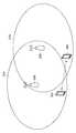
図1は、D2D通信のユースケースの具体例を説明するための第1の説明図である。図1を参照すると、複数のUE10及びeNB20が示されている。第1のユースケースとして、例えば、ネットワークカバレッジ内に(例えば、eNB20のセル21内に)位置するUE10A及びUE10Bが、D2D通信を行う。このようなD2D通信をインカバレッジ(In-Coverage)のD2D通信と呼ぶ。第2のユースケースとして、例えば、ネットワークカバレッジ外に位置するUE10C及びUE10Dが、D2D通信を行う。このようなD2D通信をアウトカバレッジ(Out-of-Coverage)のD2D通信と呼ぶ。第3のユースケースとして、例えば、ネットワークカバレッジ内に位置するUE10Eと、ネットワークカバレッジ外に位置するUE10Fとが、D2D通信を行う。このようなD2D通信をパーシャルカバレッジ(Partial-Coverage)のD2D通信と呼ぶ。パブリックセーフティの観点から、アウトカバレッジのD2D通信、及びパーシャルカバレッジのD2D通信も重要である。なお、ネットワークカバレッジとは、セルラーネットワークのカバレッジである。即ち、セルの集合が、ネットワークカバレッジとなる。 FIG. 1 is a first explanatory diagram for describing a specific example of a use case of D2D communication. Referring to FIG. 1, a plurality of
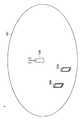
図2は、D2D通信のユースケースの具体例を説明するための第2の説明図である。図2を参照すると、UE10A及びUE10B、並びにeNB20A及びeNB20Bが、示されている。この例では、eNB20Aは、第1のMNO(Mobile Network Operator)により運用され、eNB20Bは、第2のMNOにより運用されている。そして、第1のネットワークカバレッジ内に(例えば、eNB20Aのセル21A内に)位置するUE10Aと、第2のネットワークカバレッジ(例えば、eNB20Bのセル21B内に)位置するUE10Bとが、D2D通信を行う。パブリックセーフティの観点から、このようなD2D通信も重要である。 FIG. 2 is a second explanatory diagram for describing a specific example of a use case of D2D communication. Referring to FIG. 2,
(D2D通信までの流れ)
例えば、同期(Synchronization)、ディスカバリ(Discovery)、及び接続の確立が順に行われ、その後、D2D通信が行われる。以下、同期、ディスカバリ及び接続確立の各ステップについての考察を説明する。(Flow to D2D communication)
For example, synchronization, discovery, and connection establishment are sequentially performed, and then D2D communication is performed. In the following, consideration of each step of synchronization, discovery and connection establishment will be described.
(a)同期
2つのUEが、ネットワークカバレッジ内に位置する場合、上記2つのUEは、上記eNBからのダウンリンク信号を用いてeNBとの同期を獲得することにより、互いにある程度同期することが可能である。(A) Synchronization When two UEs are located in the network coverage, the two UEs can synchronize with each other to some extent by acquiring synchronization with the eNB using a downlink signal from the eNB. It is.
一方、D2D通信を行おうとする2つのUEのうち少なくとも一方が、ネットワークカバレッジ外に位置する場合、上記2つのUEのうちの少なくとも一方が、D2D通信での同期のために同期信号を送信する必要がある。 On the other hand, when at least one of the two UEs trying to perform D2D communication is located outside the network coverage, at least one of the two UEs needs to transmit a synchronization signal for synchronization in D2D communication. There is.
(b)他のUEのディスカバリ
他のUEのディスカバリは、例えば、ディスカバリ信号(Discovery Signal)の送受信により行われる。より具体的には、例えば、2つのUEのうちの一方のUEが、ディスカバリ信号を送信し、当該2つのUEのうちの他方のUEが、当該ディスカバリ信号を受信して、上記一方のUEとの通信を試みる。(B) Discovery of other UEs Discovery of other UEs is performed, for example, by transmitting and receiving a discovery signal. More specifically, for example, one UE out of two UEs transmits a discovery signal, and the other UE out of the two UEs receives the discovery signal, and Try to communicate.
ディスカバリ信号は、時間方向において所定のタイミングで送信されていることが望ましい。これにより、受信側のUEが上記ディスカバリ信号の受信を試みるタイミングを限定することができる。なお、前提として、D2D通信を行おうとする2つのUEは、ディスカバリ信号の受信前に予め同期を獲得しておく。 The discovery signal is preferably transmitted at a predetermined timing in the time direction. As a result, the timing at which the receiving-side UE attempts to receive the discovery signal can be limited. As a premise, the two UEs that intend to perform D2D communication acquire synchronization in advance before receiving the discovery signal.
(c)接続確立
D2D通信を行おうとする2つのUEは、例えば以下のように接続を確立し得る。まず、第1のUEがディスカバリ信号を送信し、第2のUEが当該ディスカバリ信号を受信する。その後、第2のUEは、接続の確立を要求する要求メッセージを第1のUEに送信する。そして、第1のUEは、上記要求メッセージに応じて、接続の確立が完了したことを示す完了メッセージを第2のUEに送信する。(C) Connection establishment Two UEs trying to perform D2D communication can establish a connection as follows, for example. First, the first UE transmits a discovery signal, and the second UE receives the discovery signal. Thereafter, the second UE sends a request message requesting establishment of a connection to the first UE. Then, in response to the request message, the first UE transmits a completion message indicating that the establishment of the connection is completed to the second UE.
(eNBにより送信される同期信号)
LTEでは、eNBは、同期信号として、PSS(Primary Synchronization Signal)及びSSS(Secondary Synchronization Signal)を送信する。PSS及びSSSは、無線フレーム(Radio Frame)のフレーム構造(Frame Structure)における所定のタイミングで送信される。以下、図3及び図4を参照して、FDD(Frequency Division Duplex)及びTDD(Time Division Duplex)におけるPSS及びSSSのタイミングの具体例を説明する。(Synchronization signal transmitted by eNB)
In LTE, the eNB transmits PSS (Primary Synchronization Signal) and SSS (Secondary Synchronization Signal) as synchronization signals. The PSS and SSS are transmitted at a predetermined timing in the frame structure of a radio frame. Hereinafter, with reference to FIG.3 and FIG.4, the specific example of the timing of PSS and SSS in FDD (Frequency Division Duplex) and TDD (Time Division Duplex) is demonstrated.
図3は、FDDにおけるPSS及びSSSのタイミングの例を説明するための説明図である。図3を参照すると、無線フレームに含まれる10個のサブフレームが示されている。FDDでは、サブフレーム番号が0、5であるサブフレーム(即ち、1番目のサブフレーム及び6番目のサブフレーム)の各々で、PSS及びSSSが送信される。より具体的には、これらのサブフレームの各々に含まれる第1スロットの6番目のシンボルでSSSが送信され、上記第1スロットの7番目のシンボルでPSSが送信される。 FIG. 3 is an explanatory diagram for explaining an example of the timing of PSS and SSS in FDD. Referring to FIG. 3, ten subframes included in a radio frame are illustrated. In FDD, PSS and SSS are transmitted in each of subframes whose subframe numbers are 0 and 5 (that is, the first subframe and the sixth subframe). More specifically, SSS is transmitted by the sixth symbol of the first slot included in each of these subframes, and PSS is transmitted by the seventh symbol of the first slot.
図4は、TDDにおけるPSS及びSSSのタイミングの例を説明するための説明図である。図4を参照すると、無線フレームに含まれる10個のサブフレームが示されている。TDDでは、サブフレーム番号が1、6であるサブフレーム(即ち、2番目のサブフレーム及び7番目のサブフレーム)の各々で、PSSが送信される。より具体的には、これらのサブフレームの各々に含まれる第1スロットの3番目のシンボルで、PSSが送信される。また、
TDDでは、サブフレーム番号が0、5であるサブフレーム(即ち、1番目のサブフレーム及び6番目のサブフレーム)の各々で、SSSが送信される。より具体的には、これらのサブフレームの各々に含まれる第2スロットの7番目のシンボルで、SSSが送信される。FIG. 4 is an explanatory diagram for explaining an example of the timing of PSS and SSS in TDD. Referring to FIG. 4, ten subframes included in a radio frame are shown. In TDD, a PSS is transmitted in each of subframes having
In TDD, the SSS is transmitted in each of the subframes whose subframe numbers are 0 and 5 (that is, the first subframe and the sixth subframe). More specifically, the SSS is transmitted in the seventh symbol of the second slot included in each of these subframes.
UEは、PSSの検出により、サブフレーム毎のタイミングを知得することができる。また、UEは、SSSの検出により、どのサブフレームが♯0のサブフレームであるかを知得することができる。 The UE can know the timing for each subframe by detecting the PSS. Further, the UE can know which subframe is the subframe of # 0 by detecting the SSS.
さらに、UEは、PSSのシーケンスに基づいて、3つのセルグループの中から、PSSを送信するeNBにより形成されるセルが属するセルグループを識別することができる。また、UEは、SSSのシーケンスに基づいて、1つのセルグループに属する168のセル候補の中から、SSSを送信するeNBにより形成されるセルを識別することができる。即ち、UEは、PSSのシーケンス及びSSSのシーケンスに基づいて、504個のセル候補の中から、PSS及びSSSを送信するeNBにより形成されるセルを識別することができる。 Furthermore, the UE can identify the cell group to which the cell formed by the eNB that transmits the PSS belongs, from among the three cell groups, based on the PSS sequence. Moreover, UE can identify the cell formed by eNB which transmits SSS from 168 cell candidates which belong to one cell group based on the sequence of SSS. That is, the UE can identify a cell formed by the eNB that transmits the PSS and the SSS from 504 cell candidates based on the PSS sequence and the SSS sequence.
(D2D通信の同期信号)
例えば、UEが、ネットワークカバレッジ内に位置する場合には、eNBにより送信される同期信号に基づいて、D2D通信のために同期をとる。例えば、UEが、ネットワークカバレッジ外に位置する場合には、他のUEにより送信される同期信号に基づいて、D2D通信のために同期をとる。なお、同期信号は、リレーされた信号であり得る。(Synchronous signal for D2D communication)
For example, if the UE is located within the network coverage, it is synchronized for D2D communication based on a synchronization signal transmitted by the eNB. For example, when the UE is located outside the network coverage, synchronization is performed for D2D communication based on a synchronization signal transmitted by another UE. Note that the synchronization signal can be a relayed signal.
D2D通信のために端末装置により用いられる同期信号は、様々な属性を有し得る。例えば、同期信号は、送信元の属性を有し得る。当該送信元は、eNB又はUEである。例えば、同期信号は、リレーの有無の属性を有し得る。 The synchronization signal used by the terminal device for D2D communication may have various attributes. For example, the synchronization signal may have a sender attribute. The transmission source is an eNB or a UE. For example, the synchronization signal may have a relay presence / absence attribute.
同期信号が無線でリレーされる場合には、中心周波数の精度が劣化することが懸念される。そのため、リレーの回数(ホップ数)がより少ないことが望ましい。 When the synchronization signal is relayed wirelessly, there is a concern that the accuracy of the center frequency is degraded. Therefore, it is desirable that the number of relays (hops) is smaller.
同期信号の送信元は、UEよりもeNBが望ましい。UEの発振器の精度よりも、eNBの発振器の精度の方が高いからである。 The transmission source of the synchronization signal is preferably eNB rather than UE. This is because the accuracy of the oscillator of the eNB is higher than the accuracy of the oscillator of the UE.
(D2D通信で使用可能な無線リソース)
(a)リソースプール
D2D通信で使用可能な無線リソースとして、リソースプールと呼ばれる無線リソースが用意される。当該リソースプールとして、周期的な(periodic)無線リソースが考えられている。例えば、リソースプールは、周期(period)及び(時間方向の)オフセットなどにより示される。(Radio resources that can be used in D2D communication)
(A) Resource Pool Radio resources called resource pools are prepared as radio resources that can be used in D2D communication. Periodic radio resources are considered as the resource pool. For example, the resource pool is indicated by a period and an offset (in the time direction).
リソースプールの使用の手法として2つの手法があり得る。第1の手法では、管理ノード(例えば、eNB又はUE)が、リソースプールの中から、無線リソースをUEに割り当て、当該無線リソースを当該UEに通知する。当該UEは、割り当てられた上記無線リソースでD2D通信を行うことができる。第2の手法では、UEは、リソースプールの中から、無線リソースを選択し、当該無線リソースでD2D通信を行う。上記第1の手法は、ノンコンテンションベースの手法であり、衝突が起きない。一方、上記第2の手法は、コンテンションベースの手法であり、衝突が起き得る。 There are two possible approaches for using resource pools. In the first method, a management node (for example, eNB or UE) allocates a radio resource to a UE from the resource pool and notifies the UE of the radio resource. The UE can perform D2D communication using the assigned radio resource. In the second method, the UE selects a radio resource from the resource pool and performs D2D communication using the radio resource. The first method is a non-contention based method and does not cause a collision. On the other hand, the second method is a contention-based method, and a collision can occur.
(b)複数のリソースプール
複数のリソースプールが用意されることも当然に考えられる。この場合に、リソースプールの周期及びオフセットは、他のリソースプールの周期及びオフセットと異なる場合もある。なお、リソースプールの周期は、他のリソースプールの周期と同じであるが、当該リソースプールのオフセットは、当該他のリソースプールのオフセットと異なる場合もある。(B) A plurality of resource pools It is naturally considered that a plurality of resource pools are prepared. In this case, the period and offset of the resource pool may be different from the period and offset of other resource pools. The cycle of the resource pool is the same as the cycle of other resource pools, but the offset of the resource pool may be different from the offset of the other resource pool.
以下、図5を参照して、セルラーシステムにおける時間の単位である無線フレーム及びサブフレームを説明し、図6を参照して、リソースプールの具体例を説明する。 Hereinafter, radio frames and subframes, which are units of time in the cellular system, will be described with reference to FIG. 5, and specific examples of resource pools will be described with reference to FIG.
図5は、セルラーシステムにおける無線フレーム及びサブフレームを説明するための説明図である。図5を参照すると、無線フレームと、1つの無線フレームに含まれる10個のサブフレームとが示されている。各無線フレームは、10msであり、各サブフレームは、1msである。各無線フレームは、0〜1023のいずれかであるSFN(System Frame Number)を有し、1024個の無線フレームが繰り返し現れる。 FIG. 5 is an explanatory diagram for explaining radio frames and subframes in the cellular system. Referring to FIG. 5, a radio frame and 10 subframes included in one radio frame are illustrated. Each radio frame is 10 ms, and each subframe is 1 ms. Each radio frame has an SFN (System Frame Number) of 0 to 1023, and 1024 radio frames repeatedly appear.
図6は、リソースプールの例を説明するための説明図である。図6を参照すると、2つのリソースプール(即ち、リソースプール#1及びリソースプール#2)が示されている。D2D通信で使用可能な無線リソースが周期的にサブフレームに配置されることが考えられる。例えば、リソースプール#1は、周期33で反復するサブフレーム31の無線リソースであり、リソースプール#2は、周期37で反復するサブフレーム35の無線リソースである。例えば、周期33は、200msであり、周期37は、400msである。なお、この例では、リソースプール#1及びリソースプール#2は、オフセットが異なる。 FIG. 6 is an explanatory diagram for explaining an example of a resource pool. Referring to FIG. 6, two resource pools (ie,
(c)リソースプールで送信される信号/情報
例えば、リソースプールでは、同期信号(synchronization signal)及び同期情報(information of synchronization)が、代表のUEにより送信される。また、UEは、リソースプールのうちの、同期信号及び同期情報が送信される無線リソース以外の無線リソースで、D2D通信を行う。以下、この点について図7を参照して具体例を説明する。(C) Signal / information transmitted in resource pool For example, in a resource pool, a synchronization signal and information of synchronization are transmitted by a representative UE. Moreover, UE performs D2D communication with radio | wireless resources other than the radio | wireless resource to which a synchronous signal and synchronous information are transmitted among resource pools. Hereinafter, a specific example of this point will be described with reference to FIG.
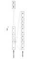
図7は、リソースプールで送信される信号及び情報の例を説明するための説明図である。図7を参照すると、N個のリソースプール(即ち、リソースプール#1〜#N)が示されている。N個のリソースプールの各々で、同期信号及び同期情報が送信される。また、N個のリソースプールの各々で、同期信号及び上記情報が送信される無線リソース以外の無線リソースで、D2D通信が行われ得る。なお、1個のUEが、2つ以上のリソースプールで、同期信号及び同期情報を送信してもよい。 FIG. 7 is an explanatory diagram for explaining an example of signals and information transmitted in the resource pool. Referring to FIG. 7, N resource pools (that is,
<<2.本開示の実施形態に係る技術的課題>>
まず、図8を参照して、本開示の実施形態に係る技術的課題を説明する。<< 2. Technical Problem According to Embodiment of Present Disclosure >>
First, a technical problem according to an embodiment of the present disclosure will be described with reference to FIG.
(想定される事項)
例えば、D2D通信で使用可能な無線リソースとして、周期的な無線リソースが割り当てられる。例えば、無線フレームの整数倍の周期で、特定のサブフレームの無線リソースが、D2D通信で使用可能な無線リソースとして割り当てられる。そして、当該特定のサブフレームでD2D通信が行われる。(Assumed matters)
For example, periodic radio resources are allocated as radio resources that can be used in D2D communication. For example, a radio resource of a specific subframe is allocated as a radio resource that can be used in D2D communication at a cycle that is an integral multiple of the radio frame. Then, D2D communication is performed in the specific subframe.
例えば、TDDキャリアでD2D通信が行われる場合に、ネットワークカバレッジ内では、当該TDDキャリアのUL/DLコンフィギュレーションのアップリンクサブフレームの無線リソースが、D2D通信で使用可能な無線リソースとして割り当てられる。そして、当該アップリンクサブフレームで、D2D通信が行われる。以下、この点について図8を参照して、具体例を説明する。 For example, when D2D communication is performed on a TDD carrier, the radio resource of the uplink subframe of the UL / DL configuration of the TDD carrier is allocated as a radio resource that can be used in D2D communication within the network coverage. Then, D2D communication is performed in the uplink subframe. Hereinafter, a specific example of this point will be described with reference to FIG.
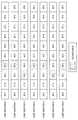
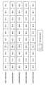
図8は、UL/DLコンフィギュレーションを説明するための説明図である。図8を参照すると、TDDキャリアのUL/DLコンフィギュレーションとして選択され得る7つのコンフィギュレーション(コンフィギュレーション0〜6)が示されている。各コンフィギュレーションは、無線フレームに含まれる10個のサブフレームの各々をダウンリンクサブフレーム、アップリンクサブフレーム又はスペシャルサブフレームとして定める。一例として、TDDキャリアのUL/DLコンフィギュレーションが、コンフィギュレーション2である場合に、サブフレーム番号が2、7であるサブフレームのうちのいずれかの無線リソースが、D2D通信で使用可能な無線リソースとして割り当てられる。別の例として、TDDキャリアのUL/DLコンフィギュレーションが、コンフィギュレーション3である場合に、サブフレーム番号が2、3、4であるサブフレームのうちのいずれかの無線リソースが、D2D通信で使用可能な無線リソースとして割り当てられる。 FIG. 8 is an explanatory diagram for explaining the UL / DL configuration. Referring to FIG. 8, there are shown seven configurations (configurations 0-6) that may be selected as UL / DL configurations for a TDD carrier. Each configuration defines each of 10 subframes included in a radio frame as a downlink subframe, an uplink subframe, or a special subframe. As an example, when the UL / DL configuration of the TDD carrier is
(第1の技術的課題)
しかし、TDDキャリアのUL/DLコンフィギュレーションが動的に変更される場合には、D2D通信が行われていたアップリンクサブフレームが、ダウンリンクサブフレーム又はスペシャルサブフレームに変更され得る。その結果、ダウンリンクサブフレーム又はスペシャルサブフレームでD2D通信が行われ得る。即ち、セルラー通信規格に反したD2D通信が行われてしまう可能性がある。(First technical problem)
However, when the UL / DL configuration of the TDD carrier is dynamically changed, an uplink subframe in which D2D communication is performed may be changed to a downlink subframe or a special subframe. As a result, D2D communication can be performed in a downlink subframe or a special subframe. That is, there is a possibility that D2D communication contrary to the cellular communication standard is performed.
図8を再び参照すると、例えば、TDDキャリアのUL/DLコンフィギュレーションが、コンフィギュレーション2であり、サブフレーム番号が7であるサブフレームの無線リソースが、D2D通信で使用可能な無線リソースとして割り当てられる。その後、上記UL/DLコンフィギュレーションが、コンフィギュレーション2からコンフィギュレーション3に変更される。そのため、サブフレーム番号が7であるサブフレームが、ダウンリンクサブフレームになる。その結果、ダウンリンクサブフレームでD2D通信が行われ得る。 Referring to FIG. 8 again, for example, the radio resource of the subframe having the UL / DL configuration of the TDD carrier is
そこで、TDDの環境下で端末装置が適切にD2D通信を行うことを可能にする仕組みが提供されることが望ましい。より具体的には、例えば、TDD環境下で端末装置が継続してアップリンクサブフレームでD2D通信を行うことを可能にする仕組みが提供されることが望ましい。Therefore, it is desirable to provide a mechanism that allows the terminal device to appropriately perform D2D communication in a TDD environment. More specifically, for example, it is desirable to provide a mechanism that allows a terminal device to continuously perform D2D communication in an uplink subframe under a TDD environment.
(第2の技術的課題)
また、TDDキャリアのUL/DLコンフィギュレーションのアップリンクサブフレームの無線リソースが、D2D通信で使用可能な無線リソースとして自由に割り当てられると、基地局及び端末装置の間でのTDDでの無線通信に悪影響が生じ得る。(Second technical problem)
In addition, when radio resources of uplink subframes in the UL / DL configuration of the TDD carrier are freely allocated as radio resources that can be used in D2D communication, radio communication using TDD between the base station and the terminal device is possible. Negative effects can occur.
例えば、アップリンクサブフレームがD2D通信に割り当てられると、当該アップリンクサブフレームでは、端末装置は、アップリンク信号を送信しない。そのため、例えば、端末装置のアップリンクでの通信品質が低下し得る。一例として、端末装置のユーザが通話する場合に、端末装置による音声データの送信間隔が長くなり得る。そのため、音声データの送信に遅延が生じ得る。その結果、通話品質が低下する可能性がある。別の例として、アップリンクでの端末装置によるACK/NACK(即ち、ダウンリンクデータについてのACK/NACK)の送信が、適切なタイミングで行うことが困難になることも考えられる。具体的には、アップリンクでのACK/NACK送信にエラー又は遅延が生じることも考えられる。 For example, when an uplink subframe is assigned to D2D communication, the terminal apparatus does not transmit an uplink signal in the uplink subframe. Therefore, for example, the communication quality in the uplink of the terminal device can be reduced. As an example, when a user of a terminal device makes a call, the transmission interval of voice data by the terminal device can be long. Therefore, there may be a delay in the transmission of audio data. As a result, the call quality may be degraded. As another example, it may be difficult to transmit ACK / NACK (that is, ACK / NACK for downlink data) by the terminal device on the uplink at an appropriate timing. Specifically, an error or delay may occur in ACK / NACK transmission on the uplink.
そこで、TDDの環境下で端末装置が適切にD2D通信を行うことを可能にする仕組みが提供されることが望ましい。より具体的には、例えば、D2D通信に起因して基地局と端末装置との間のTDDでの無線通信に生じる悪影響を小さくすることを可能にする仕組みが提供されることが望ましい。Therefore, it is desirable to provide a mechanism that allows the terminal device to appropriately perform D2D communication in a TDD environment. More specifically, for example, it is desirable to provide a mechanism that makes it possible to reduce adverse effects that occur in TDD wireless communication between a base station and a terminal device due to D2D communication.
<<3.通信システムの概略的な構成>>
続いて、図9を参照して、本開示の実施形態に係る通信システム1の概略的な構成を説明する。図9は、本開示の実施形態に係る通信システム1の概略的な構成の一例を示す説明図である。図9を参照すると、通信システム1は、基地局100及び端末装置200を含む。通信システム1は、例えば、セルラーシステムであり、一例として、LTE、LTE−Advanced、又はこれらに準ずる通信規格に準拠したシステムである。<< 3. Schematic configuration of communication system >>
Next, a schematic configuration of the
(基地局100)
基地局100は、端末装置との無線通信を行う。例えば、基地局100は、基地局100のセル101内に位置する端末装置200との無線通信を行う。(Base station 100)
The
とりわけ本開示の実施形態では、基地局100は、TDDで無線通信を行う。具体的には、例えば、基地局100は、TDDキャリアを使用して、ダウンリンクサブフレームでダウンリンク信号を送信し、アップリンクサブフレームでアップリンク信号を受信する。上記TDDキャリアは、TDDでの無線通信のためのキャリアであり、例えば、コンポーネントキャリアである。
In particular, in the embodiment of the present disclosure, the
なお、図9には、通信システム1に含まれる1つの基地局(即ち、基地局100)のみが示されるが、当然ながら、通信システム1は、複数の基地局を含み得る。そして、複数の基地局のセルの集合が、ネットワークカバレッジ(即ち、セルラーネットワークのカバレッジ)となる。 Although FIG. 9 shows only one base station (that is, base station 100) included in the
(端末装置200)
端末装置200は、基地局との無線通信を行う。例えば、端末装置200は、基地局100のセル101内に位置する場合に、基地局100との無線通信を行う。例えば、端末装置200は、TDDで基地局との無線通信を行う。具体的には、例えば、端末装置200は、上記TDDキャリアを使用して、ダウンリンクサブフレームでダウンリンク信号を受信し、アップリンクサブフレームでアップリンク信号を送信する。(Terminal device 200)
The
とりわけ本開示の実施形態では、端末装置200は、D2D通信を行う。例えば、端末装置200は、他の端末装置200とのD2D通信を行う。 In particular, in the embodiment of the present disclosure, the
<<4.各装置の構成>>
続いて、図10及び図11を参照して、基地局100及び端末装置200の構成の一例を説明する。<< 4. Configuration of each device >>
Next, an example of the configuration of the
<4.1.基地局の構成>>
図10は、本開示の実施形態に係る基地局100の構成の一例を示すブロック図である。図10を参照すると、基地局100は、アンテナ部110、無線通信部120、ネットワーク通信部130、記憶部140及び処理部150を備える。<4.1. Base station configuration >>
FIG. 10 is a block diagram illustrating an exemplary configuration of the
(アンテナ部110)
アンテナ部110は、無線信号を受信し、受信された無線信号を無線通信部120へ出力する。また、アンテナ部110は、無線通信部120により出力された送信信号を送信する。(Antenna unit 110)
The
(無線通信部120)
無線通信部120は、信号を送受信する。例えば、無線通信部120は、端末装置へのダウンリンク信号を送信し、端末装置からのアップリンク信号を受信する。(Wireless communication unit 120)
The
(ネットワーク通信部130)
ネットワーク通信部130は、情報を送受信する。例えば、ネットワーク通信部130は、他のノードへの情報を送信し、他のノードからの情報を受信する。例えば、上記他のノードは、他の基地局及びコアネットワークノードを含む。(Network communication unit 130)
The
(記憶部140)
記憶部140は、基地局100の動作のためのプログラム及びデータを記憶する。(Storage unit 140)
The
(処理部150)
処理部150は、基地局100の様々な機能を提供する。処理部150は、情報取得部151及び制御部153を含む。なお、処理部150は、これらの構成要素以外の他の構成要素をさらに含み得る。即ち、処理部150は、これらの構成要素の動作以外の動作も行い得る。(Processing unit 150)
The
情報取得部151及び制御部153の動作は、後に詳細に説明する。 The operations of the
<4.2.端末装置の構成>>
図11は、本開示の実施形態に係る端末装置200の構成の一例を示すブロック図である。図11を参照すると、端末装置200は、アンテナ部210、無線通信部220、記憶部230及び処理部240を備える。<4.2. Terminal device configuration >>
FIG. 11 is a block diagram illustrating an exemplary configuration of the
(アンテナ部210)
アンテナ部210は、無線信号を受信し、受信された無線信号を無線通信部220へ出力する。また、アンテナ部210は、無線通信部220により出力された送信信号を送信する。(Antenna unit 210)
The
(無線通信部220)
無線通信部220は、信号を送受信する。例えば、無線通信部220は、基地局からのダウンリンク信号を受信し、基地局へのアップリンク信号を送信する。また、例えば、無線通信部220は、他の端末装置からの信号を受信し、他の端末装置への信号を送信する。(Wireless communication unit 220)
The
(記憶部230)
記憶部230は、端末装置200の動作のためのプログラム及びデータを記憶する。(Storage unit 230)
The
(処理部240)
処理部240は、端末装置200の様々な機能を提供する。処理部240は、情報取得部241及び制御部243を含む。なお、処理部240は、これらの構成要素以外の他の構成要素をさらに含み得る。即ち、処理部240は、これらの構成要素の動作以外の動作も行い得る。(Processing unit 240)
The
情報取得部241及び制御部243の動作は、後に詳細に説明する。 The operations of the
<<5.本開示の実施形態に係る技術的特徴>>
続いて、図12〜図19を参照して、本開示の実施形態に係る技術的特徴を説明する。<< 5. Technical features according to embodiments of the present disclosure >>
Subsequently, the technical features according to the embodiment of the present disclosure will be described with reference to FIGS.
<5.1.第1の技術的特徴>
まず、図12〜図15を参照して、本開示の実施形態に係る第1の技術的特徴を説明する。当該第1の技術的特徴は、例えば、上述した本開示の実施形態に係る第1の技術的課題に対応する特徴である。<5.1. First technical feature>
First, the first technical feature according to the embodiment of the present disclosure will be described with reference to FIGS. The first technical feature is a feature corresponding to, for example, the first technical problem according to the embodiment of the present disclosure described above.
(UL/DLコンフィギュレーションの動的な変更)
基地局100(制御部153)は、TDDキャリアのUL/DLコンフィギュレーションを動的に変更する。(Dynamic change of UL / DL configuration)
The base station 100 (control unit 153) dynamically changes the UL / DL configuration of the TDD carrier.
(a)複数のコンフィギュレーション
例えば、基地局100(制御部153)は、複数のコンフィギュレーションのうちの1つのコンフィギュレーションから、当該複数のコンフィギュレーションのうちの別のコンフィギュレーションに、上記UL/DLコンフィギュレーションを変更する。(A) A plurality of configurations For example, the base station 100 (control unit 153) changes the UL / DL from one configuration of the plurality of configurations to another configuration of the plurality of configurations. Change the configuration.
例えば、上記複数のコンフィギュレーションは、図8に示される6つのコンフィギュレーション(コンフィギュレーション0〜6)である。即ち、基地局100(制御部153)は、7つのコンフィギュレーションのうちの1つのコンフィギュレーションから別のコンフィギュレーションに、上記UL/DLコンフィギュレーションを変更する。
For example, the plurality of configurations are the six configurations (
具体的な処理として、例えば、制御部153は、上記UL/DLコンフィギュレーションを指定する動作パラメータを変更することにより、上記UL/DLコンフィギュレーションを変更する。なお、これは具体的な処理の単なる一例であり、当然ながら、制御部153は、実装に応じた他の処理を行ってもよい。 As a specific process, for example, the
(b)UL/DLコンフィギュレーションの通知
例えば、基地局100(制御部153)は、上記TDDキャリアの上記UL/DLコンフィギュレーションを端末装置に通知する。(B) Notification of UL / DL configuration For example, the base station 100 (control unit 153) notifies the terminal device of the UL / DL configuration of the TDD carrier.
(b−1)通知手法
−システム情報の報知
例えば、基地局100(制御部153)は、上記UL/DLコンフィギュレーションを示すシステム情報の報知により、上記UL/DLコンフィギュレーションを端末装置に通知する。例えば、上記システム情報は、SIB(System Information Block)1である。(B-1) Notification Method-System Information Notification For example, the base station 100 (the control unit 153) notifies the terminal device of the UL / DL configuration by notification of system information indicating the UL / DL configuration. . For example, the system information is SIB (System Information Block) 1.
これにより、例えば、接続モードの端末装置のみではなく、アイドルモードの端末装置も、上記UL/DLコンフィギュレーションを知ることが可能になる。 Thereby, for example, not only the terminal device in the connection mode but also the terminal device in the idle mode can know the UL / DL configuration.
−個別のシグナリング
基地局100(制御部153)は、上記システム情報の報知に加えて、個別のシグナリングにより、上記UL/DLコンフィギュレーションを接続モードの端末装置に通知してもよい。当該個別のシグナリングは、RRC(Radio Resource Control)シグナリングであってもよい。接続モードの当該端末装置は、例えば、端末装置200である。-Individual signaling The base station 100 (the control unit 153) may notify the UL / DL configuration to the terminal device in the connection mode by individual signaling in addition to the notification of the system information. The individual signaling may be RRC (Radio Resource Control) signaling. The terminal device in the connection mode is, for example, the
これにより、例えば、上記UL/DLコンフィギュレーションの変更の迅速な通知を行うことが可能になる。 Thereby, for example, it is possible to promptly notify the change of the UL / DL configuration.
(b−2)端末装置200の動作
例えば、端末装置200(情報取得部241)は、上記UL/DLコンフィギュレーションを取得する。そして、端末装置200(制御部243)は、上記UL/DLコンフィギュレーションに従って、上記TDDキャリアを使用して基地局との無線通信を行う。(B-2) Operation of
(D2D通信用の無線リソースの通知)
基地局100(制御部153)は、上記UL/DLコンフィギュレーションに適したD2D通信用の無線リソースを端末装置に通知する。当該無線リソースは、上記TDDキャリアの無線リソースである。なお、以下では、「D2D通信用の無線リソース」は、単に「D2Dリソース」と呼ばれ得る。(Notification of radio resource for D2D communication)
The base station 100 (control unit 153) notifies the terminal device of radio resources for D2D communication suitable for the UL / DL configuration. The radio resource is a radio resource of the TDD carrier. In the following, the “radio resource for D2D communication” may be simply referred to as “D2D resource”.
一方、端末装置200(情報取得部241)は、上記UL/DLコンフィギュレーション(即ち、基地局100により動的に変更されるTDDキャリアのUL/DLコンフィギュレーション)に適した上記D2Dリソースを示す情報を取得する。そして、端末装置200は、上記D2Dリソースを使用してD2D通信を行う。端末装置200の制御部243は、上記D2Dリソースを使用したD2D通信を制御する。 On the other hand, the terminal device 200 (information acquisition unit 241) indicates information indicating the D2D resource suitable for the UL / DL configuration (that is, the UL / DL configuration of the TDD carrier that is dynamically changed by the base station 100). To get. And the
(a)UL/DLコンフィギュレーションに適したD2Dリソース
上記UL/DLコンフィギュレーションに適した上記D2Dリソースは、上記UL/DLコンフィギュレーションの少なくとも1つのアップリンクサブフレームの無線リソースである。(A) D2D resource suitable for UL / DL configuration The D2D resource suitable for the UL / DL configuration is a radio resource of at least one uplink subframe of the UL / DL configuration.
図8を再び参照すると、一例として、上記UL/DLコンフィギュレーションがコンフィギュレーション1である場合には、上記UL/DLコンフィギュレーションに適したD2Dリソースは、サブフレーム番号が2、3、7、8であるサブフレームのうちの少なくとも1つのサブフレームの無線リソースである。別の例として、上記UL/DLコンフィギュレーションがコンフィギュレーション4である場合には、上記UL/DLコンフィギュレーションに適したD2Dリソースは、サブフレーム番号が2、3であるサブフレームのうちの少なくとも1つのサブフレームの無線リソースである。 Referring to FIG. 8 again, as an example, when the UL / DL configuration is
なお、例えば、D2Dリソースは、周期的な無線リソースである。より具体的には、例えば、D2Dリソースは、無線フレームの整数倍の周期で反復する無線リソースである。この場合に、当該周期が1無線フレームでない限り、D2Dリソースは、限定された無線フレームの中の特定のサブフレームの無線リソースである。D2Dリソースは、リソースプールと呼ばれ得る。周期(及びオフセット)を各々有する複数のリソースプールが用意され得る。D2Dリソースは、無線フレームの周期(及びオフセット)並びにサブフレームにより示され得る。 For example, the D2D resource is a periodic radio resource. More specifically, for example, the D2D resource is a radio resource that repeats at a cycle that is an integral multiple of the radio frame. In this case, unless the period is one radio frame, the D2D resource is a radio resource of a specific subframe in the limited radio frame. A D2D resource may be referred to as a resource pool. A plurality of resource pools each having a period (and offset) may be prepared. The D2D resource may be indicated by the period (and offset) of the radio frame and the subframe.
(b)通知手法
例えば、基地局100(制御部153)は、上記UL/DLコンフィギュレーションに適した上記D2Dリソースを示すシステム情報の報知により、上記D2Dリソースを端末装置に通知する。これにより、例えば、接続モードの端末装置のみではなく、アイドルモードの端末装置も、上記D2Dリソースを知ることが可能になる。(B) Notification method For example, the base station 100 (the control unit 153) notifies the terminal device of the D2D resource by reporting system information indicating the D2D resource suitable for the UL / DL configuration. Thereby, for example, not only the terminal device in the connection mode but also the terminal device in the idle mode can know the D2D resource.
なお、基地局100(制御部153)は、個別のシグナリングにより、上記D2Dリソースを端末装置200に通知してもよい。当該個別のシグナリングは、RRCシグナリングであってもよい。 Note that the base station 100 (the control unit 153) may notify the
(c)通知形態
(c−1)第UL/DLコンフィギュレーションの変更に応じたD2Dリソースの通知
上述したように、基地局100(制御部153)は、上記複数のコンフィギュレーションのうちの1つのコンフィギュレーションから、上記複数のコンフィギュレーションのうちの別のコンフィギュレーションに、上記UL/DLコンフィギュレーションを変更する。(C) Notification form (c-1) Notification of D2D resources according to change of the UL / DL configuration As described above, the base station 100 (the control unit 153) is one of the plurality of configurations. The UL / DL configuration is changed from a configuration to another configuration of the plurality of configurations.
第1の通知形態として、例えば、基地局100(制御部153)は、上記UL/DLコンフィギュレーションの変更に応じて、上記別のコンフィギュレーションに適したD2Dリソースを端末装置に通知する。上記別のコンフィギュレーションに適したD2Dリソースは、上記別のコンフィギュレーションの少なくとも1つのアップリンクサブフレームの無線リソースである。 As a first notification form, for example, the base station 100 (control unit 153) notifies the terminal device of D2D resources suitable for the other configuration according to the change of the UL / DL configuration. The D2D resource suitable for the another configuration is a radio resource of at least one uplink subframe of the another configuration.
一方、端末装置200(情報取得部241)は、基地局100が端末装置200に通知するD2Dリソースを示す情報を取得する。そして、端末装置200は、基地局100が端末装置200に通知する上記D2Dリソースを使用して、D2D通信を行う。即ち、端末装置200の制御部243は、基地局100が端末装置200に通知する上記D2Dリソースを使用したD2D通信を制御する。 On the other hand, the terminal device 200 (information acquisition unit 241) acquires information indicating the D2D resource that the
以下、図12及び図13を参照して、基地局100が端末装置に通知するD2Dリソースの具体例を説明する。 Hereinafter, a specific example of the D2D resource notified from the
図12は、D2Dリソースの第1の例を説明するための説明図である。図12を参照すると、コンフィギュレーション0〜6が示されている。この例では、コンフィギュレーションごとに、1つのアップリンクサブフレームがD2Dリソースとして用意されている。例えば、コンフィギュレーション0、1、3、4、6の各々に適したD2Dリソースは、サブフレーム番号が3であるアップリンクサブフレームの無線リソースである。また、例えば、コンフィギュレーション2、5の各々に適したD2Dリソースは、サブフレーム番号が2であるアップリンクサブフレームの無線リソースである。
FIG. 12 is an explanatory diagram for describing a first example of D2D resources. Referring to FIG. 12,
図13は、UL/DLコンフィギュレーションの変更に応じたD2Dリソースの通知の例を説明するための説明図である。図13を参照すると、例えば、上記TDDキャリアの上記UL/DLコンフィギュレーションが、コンフィギュレーション0からコンフィギュレーション2に変更される。コンフィギュレーション0に適したD2Dリソースは、サブフレーム番号が3であるサブフレームの無線リソースであり、コンフィギュレーション2に適したD2Dリソースは、サブフレーム番号が2であるサブフレームの無線リソースである。この場合に、基地局100(制御部153)は、上記UL/DLコンフィギュレーションの変更に応じて、サブフレーム番号が2であるアップリンクサブフレームの無線リソースを、D2Dリソースとして端末装置に通知する。その結果、端末装置200は、上記UL/DLコンフィギュレーションの変更後には、サブフレーム番号が3であるサブフレームではD2D通信を行わず、サブフレーム番号が2であるサブフレームでD2D通信を行う。
FIG. 13 is an explanatory diagram for explaining an example of notification of a D2D resource according to a change in the UL / DL configuration. Referring to FIG. 13, for example, the UL / DL configuration of the TDD carrier is changed from
このように、例えば、上記UL/DLコンフィギュレーションが、コンフィギュレーション0、1、3、4、6のいずれかに変更された場合には、基地局100(制御部153)は、サブフレーム番号が3であるアップリンクサブフレームの無線リソースを、D2Dリソースとして端末装置に通知する。また、例えば、上記UL/DLコンフィギュレーションが、コンフィギュレーション2、5のいずれかに変更された場合には、基地局100(制御部153)は、サブフレーム番号が2であるアップリンクサブフレームの無線リソースを、D2Dリソースとして端末装置に通知する。 Thus, for example, when the UL / DL configuration is changed to any of
なお、図12の例では、D2Dリソースは、無線フレームの中の1つのサブフレームの無線リソースであるが、当然ながら、D2Dリソースは、無線フレームの中の2つ以上のサブフレームの無線リソースであってもよい。 In the example of FIG. 12, the D2D resource is a radio resource of one subframe in the radio frame, but naturally, the D2D resource is a radio resource of two or more subframes in the radio frame. There may be.
また、例えば、上記D2Dリソースは、周期的な無線リソースであり、周期(及びオフセット)を有する。この場合に、例えば、基地局100(制御部153)は、上記D2Dリソースの通知の際に、サブフレームのみではなく、周期(及びオフセット)も通知する。例えば、上記周期は、無線フレームの整数倍の周期である。 Further, for example, the D2D resource is a periodic radio resource and has a period (and an offset). In this case, for example, the base station 100 (control unit 153) notifies not only the subframe but also the period (and offset) when notifying the D2D resource. For example, the period is a period that is an integral multiple of the radio frame.
以上のように、例えば、基地局100(制御部153)は、上記UL/DLコンフィギュレーションの変更に応じて、上記別のコンフィギュレーション(即ち、変更後のコンフィギュレーション)に適したD2Dリソースを端末装置に通知する。これにより、例えば、TDD環境下で端末装置が継続してアップリンクサブフレームでD2D通信を行うことが可能になる。即ち、TDDキャリアのUL/DLサブフレームが変更されたとしても、基地局100は、変更後のコンフィギュレーションに適したD2Dリソース(アップリンクサブフレームの無線リソース)を端末装置200に通知し、端末装置200は、アップリンクサブフレームでD2D通信を行うことができる。 As described above, for example, the base station 100 (the control unit 153) transmits D2D resources suitable for the other configuration (that is, the changed configuration) in accordance with the change of the UL / DL configuration. Notify the device. Thereby, for example, the terminal device can continuously perform D2D communication in the uplink subframe in the TDD environment. That is, even if the UL / DL subframe of the TDD carrier is changed, the
なお、例えば、基地局100は、上記UL/DLコンフィギュレーションの上記変更の直前から、上記UL/DLコンフィギュレーションの次の変更の直前まで、上記別のコンフィギュレーション(即ち、変更後のコンフィギュレーション)を示すシステム情報を報知する。基地局100は、上記UL/DLコンフィギュレーションの上記変更の直前に、個別のシグナリングにより、上記別のコンフィギュレーション(即ち、変更後のコンフィギュレーション)を端末装置200に通知してもよい。 Note that, for example, the
(c−2)複数のコンフィギュレーションの各々に適したD2Dリソースの通知
上述したように、基地局100(制御部153)は、上記複数のコンフィギュレーションのうちの1つのコンフィギュレーションから、上記複数のコンフィギュレーションのうちの別のコンフィギュレーションに、上記UL/DLコンフィギュレーションを変更する。(C-2) Notification of D2D resources suitable for each of a plurality of configurations As described above, the base station 100 (the control unit 153) determines that the plurality of configurations from one configuration among the plurality of configurations. The UL / DL configuration is changed to another configuration.
第2の通知形態として、例えば、基地局100(制御部153)は、上記複数のコンフィギュレーションの各々に適したD2Dリソースを、端末装置に通知する。 As the second notification form, for example, the base station 100 (the control unit 153) notifies the terminal device of D2D resources suitable for each of the plurality of configurations.
−第1の例:コンフィギュレーションごとのD2Dリソース
第1の例として、上記複数のコンフィギュレーションの各々に適した上記無線リソースは、コンフィギュレーションごとのD2Dリソースを含む。即ち、基地局100(制御部153)は、上記複数のコンフィギュレーションに含まれるコンフィギュレーションごとのD2Dリソースを、端末装置に通知する。First Example: D2D Resource for Each Configuration As a first example, the radio resource suitable for each of the plurality of configurations includes a D2D resource for each configuration. That is, the base station 100 (control unit 153) notifies the terminal device of D2D resources for each configuration included in the plurality of configurations.
図12を再び参照すると、例えば、上記複数のコンフィギュレーションは、コンフィギュレーション0〜6であり、コンフィギュレーションごとのD2Dリソースが示されている。例えば、基地局100(制御部153)は、このようなコンフィギュレーションごとのD2Dリソースを、端末装置に通知する。 Referring to FIG. 12 again, for example, the plurality of configurations are
一方、端末装置200(情報取得部241)は、基地局100が端末装置に通知する上記UL/DLコンフィギュレーションに基づいて、上記複数のコンフィギュレーションの各々に適したD2Dリソースのうちの、上記UL/DLコンフィギュレーションに適したD2Dリソースを示す情報取得する。そして、端末装置200は、当該D2Dリソースを使用してD2D通信を行う。 On the other hand, the terminal device 200 (information acquisition unit 241), based on the UL / DL configuration notified from the
図13を再び参照すると、例えば、上記TDDキャリアの上記UL/DLコンフィギュレーションが、コンフィギュレーション0からコンフィギュレーション2に変更される。この場合に、基地局100は、コンフィギュレーション2を端末装置に通知し、端末装置200(情報取得部241)は、コンフィギュレーション0〜6の各々に適したD2Dリソースのうちの、コンフィギュレーション2に適したD2Dリソースを示す情報を取得する。そして、端末装置200は、コンフィギュレーション2に適した当該D2Dリソースで、D2D通信を行う。 Referring to FIG. 13 again, for example, the UL / DL configuration of the TDD carrier is changed from
また、例えば、上記D2Dリソースは、周期的な無線リソースであり、周期(及びオフセット)を有する。この場合に、例えば、基地局100(制御部153)は、上記D2Dリソースの通知の際に、サブフレームのみではなく、周期(及びオフセット)も通知する。例えば、上記周期は、無線フレームの整数倍の周期である。 Further, for example, the D2D resource is a periodic radio resource and has a period (and an offset). In this case, for example, the base station 100 (control unit 153) notifies not only the subframe but also the period (and offset) when notifying the D2D resource. For example, the period is a period that is an integral multiple of the radio frame.
以上のように、基地局100(制御部153)は、上記複数のコンフィギュレーションに含まれるコンフィギュレーションごとのD2Dリソースを、端末装置に通知する。これにより、例えば、TDD環境下で端末装置が継続してアップリンクサブフレームでD2D通信を行うことが可能になる。即ち、TDDキャリアのUL/DLサブフレームが変更されたとしても、端末装置200が、変更後のコンフィギュレーションに適したD2Dリソース(アップリンクサブフレームの無線リソース)を特定し、アップリンクサブフレームでD2D通信を行うことができる。 As described above, the base station 100 (the control unit 153) notifies the terminal device of the D2D resource for each configuration included in the plurality of configurations. Thereby, for example, the terminal device can continuously perform D2D communication in the uplink subframe in the TDD environment. That is, even if the UL / DL subframe of the TDD carrier is changed, the
−第2の例:複数のコンフィギュレーションに共通のD2Dリソース
第2の例として、上記複数のコンフィギュレーションの各々に適した上記無線リソースは、上記複数のコンフィギュレーションの間で共通する少なくとも1つのアップリンクサブフレームの無線リソースであってもよい。即ち、基地局100(制御部153)は、上記複数のコンフィギュレーション間で共通する少なくとも1つのアップリンクサブフレームの無線リソースを、D2Dリソースとして端末装置に通知してもよい。Second example: D2D resource common to a plurality of configurations As a second example, the radio resource suitable for each of the plurality of configurations is at least one common resource among the plurality of configurations. It may be a radio resource of a link subframe. That is, the base station 100 (the control unit 153) may notify the terminal device of radio resources of at least one uplink subframe that is common among the plurality of configurations as D2D resources.
一方、端末装置200(情報取得部241)は、基地局100が端末装置に通知するD2Dリソース(即ち、上記複数のコンフィギュレーション間で共通する少なくとも1つのアップリンクサブフレームの無線リソース)を示す情報を取得してもよい。そして、端末装置200は、基地局100が端末装置200に通知する上記D2Dリソースを使用して、D2D通信を行ってもよい。即ち、端末装置200の制御部243は、基地局100が端末装置200に通知する上記D2Dリソースを使用したD2D通信を制御してもよい。 On the other hand, the terminal device 200 (information acquisition unit 241) indicates information indicating D2D resources (that is, radio resources of at least one uplink subframe that are common among the plurality of configurations) that the
以下、図14を参照して、D2Dリソースの具体例を説明する。 Hereinafter, a specific example of the D2D resource will be described with reference to FIG.
図14は、D2Dリソースの第2の例を説明するための説明図である。図14を参照すると、コンフィギュレーション0〜6が示されている。この例では、コンフィギュレーション0〜6の間で共通するアップリンクサブフレーム(即ち、サブフレーム番号が2であるサブフレーム)の無線リソースが、D2Dリソースとして用意されている。この場合に、基地局100は、サブフレーム番号が2であるアップリンクサブフレームの無線リソースを、D2Dリソースとして端末装置に通知する。その結果、端末装置200は、上記UL/DLコンフィギュレーションの変更前及び変更後のいずれでも、サブフレーム番号が2であるサブフレームでD2D通信を行う。 FIG. 14 is an explanatory diagram for describing a second example of the D2D resource. Referring to FIG. 14,
上記複数のコンフィギュレーション間で共通するサブフレームが、サブフレーム番号が2であるサブフレームである例を説明したが、上記複数のコンフィギュレーション間で共通するサブフレームは、係る例に限定されない。例えば、上記複数のコンフィギュレーションは、7つのコンフィギュレーション(即ち、コンフィギュレーション0〜6)ではなく、当該7つのコンフィギュレーションの一部であってもよい。そして、上記複数のコンフィギュレーション間で共通するサブフレームは、サブフレーム番号が2ではないサブフレームであってもよい。以下、この点について、図15を参照して具体例を説明する。 Although an example in which the subframe common to the plurality of configurations is a subframe having a subframe number of 2 has been described, the subframe common to the plurality of configurations is not limited to the example. For example, the plurality of configurations may be a part of the seven configurations instead of the seven configurations (that is, the
図15は、D2Dリソースの第3の例を説明するための説明図である。図15を参照すると、コンフィギュレーション0、1、3、4、6が示されている。この例では、上記複数のコンフィギュレーションは、コンフィギュレーション0、1、3、4、6である。そのため、コンフィギュレーション0、1、3、4、6間で共通するアップリンクサブフレーム(例えば、サブフレーム番号が3であるサブフレーム)の無線リソースが、D2Dリソースとして用意されている。この場合に、基地局100は、サブフレーム番号が3であるアップリンクサブフレームの無線リソースを、D2Dリソースとして端末装置に通知する。その結果、端末装置200は、上記UL/DLコンフィギュレーションの変更前及び変更後のいずれでも、サブフレーム番号が3であるサブフレームでD2D通信を行う。 FIG. 15 is an explanatory diagram for describing a third example of the D2D resource. Referring to FIG. 15,
また、例えば、上記D2Dリソースは、周期的な無線リソースであり、周期(及びオフセット)を有する。この場合に、例えば、基地局100(制御部153)は、上記D2Dリソースの通知の際に、サブフレームのみではなく、周期(及びオフセット)も通知する。例えば、上記周期は、無線フレームの整数倍の周期である。 Further, for example, the D2D resource is a periodic radio resource and has a period (and an offset). In this case, for example, the base station 100 (control unit 153) notifies not only the subframe but also the period (and offset) when notifying the D2D resource. For example, the period is a period that is an integral multiple of the radio frame.
以上のように、基地局100(制御部153)は、上記複数のコンフィギュレーション間で共通する少なくとも1つのアップリンクサブフレームの無線リソースを、D2Dリソースとして端末装置に通知してもよい。これにより、例えば、TDD環境下で端末装置が継続してアップリンクサブフレームでD2D通信を行うことが可能になる。即ち、TDDキャリアのUL/DLサブフレームの変更前及び変更後のいずれでも、端末装置200は、アップリンクサブフレームでD2D通信を行うことができる。 As described above, the base station 100 (the control unit 153) may notify the terminal device of the radio resource of at least one uplink subframe that is common among the plurality of configurations as the D2D resource. Thereby, for example, the terminal device can continuously perform D2D communication in the uplink subframe in the TDD environment. That is, the
なお、例えば、上記D2Dリソースの周期(及びオフセット)も、上記複数のコンフィギュレーション間で共通であってもよい。即ち、上記複数のコンフィギュレーション間で共通するD2Dリソースが用意されてもよい。これにより、例えば、UL/DLコンフィギュレーションの変更にかかわらず、端末装置がD2DリソースでD2D通信を行うことが可能になる。 For example, the period (and offset) of the D2D resource may be common among the plurality of configurations. That is, a D2D resource common to the plurality of configurations may be prepared. Thereby, for example, the terminal device can perform D2D communication with the D2D resource regardless of the change of the UL / DL configuration.
以上のように、基地局100(制御部153)は、上記UL/DLコンフィギュレーションに適したD2Dリソースを端末装置に通知する。なお、例えば、当該D2Dリソースは、周期(及びオフセット)を有するリソースプールであり、基地局100(制御部153)は、複数のリソースプールの各々について、上記UL/DLコンフィギュレーションに適したリソースプール(D2Dリソース)を端末装置に通知し得る。 As described above, the base station 100 (the control unit 153) notifies the terminal device of D2D resources suitable for the UL / DL configuration. For example, the D2D resource is a resource pool having a period (and an offset), and the base station 100 (control unit 153) uses a resource pool suitable for the UL / DL configuration for each of a plurality of resource pools. (D2D resource) may be notified to the terminal device.
<5.2.第2の技術的特徴>
次に、図16〜図19を参照して、本開示の実施形態に係る第2の技術的特徴を説明する。当該第2の技術的特徴は、例えば、上述した本開示の実施形態に係る第2の技術的課題に対応する特徴である。<5.2. Second technical feature>
Next, a second technical feature according to an embodiment of the present disclosure will be described with reference to FIGS. The second technical feature is a feature corresponding to, for example, the second technical problem according to the embodiment of the present disclosure described above.
(UL/DLコンフィギュレーションに適したD2Dリソース)
上述したように、基地局100(制御部153)は、上記UL/DLコンフィギュレーションに適したD2D通信用の無線リソース(D2Dリソース)を端末装置に通知する。また、上記UL/DLコンフィギュレーションに適した上記D2Dリソースは、上記UL/DLコンフィギュレーションの少なくとも1つのアップリンクサブフレームの無線リソースである。(D2D resource suitable for UL / DL configuration)
As described above, the base station 100 (the control unit 153) notifies the terminal device of radio resources for D2D communication (D2D resources) suitable for the UL / DL configuration. Also, the D2D resource suitable for the UL / DL configuration is a radio resource of at least one uplink subframe of the UL / DL configuration.
(a)サブフレームに関する特徴
(a−1)2つ以上の連続するアップリンクサブフレームの一部
例えば、上記少なくとも1つのアップリンクサブフレームの各々は、上記UL/DLコンフィギュレーションの2つ以上の連続するアップリンクサブフレームに含まれる。即ち、上記UL/DLコンフィギュレーションに適した上記D2Dリソースは、上記UL/DLコンフィギュレーションの2つ以上の連続するアップリンクサブフレームに各々含まれる少なくとも1つのアップリンクサブフレームの無線リソースである。なお、上記2つ以上の連続するアップリンクサブフレームのうちの1つ以上のアップリンクサブフレームは、上記少なくとも1つのアップリンクサブフレームに含まれない。以下、図16を参照して、D2Dリソースの具体例を説明する。(A) Features related to subframes (a-1) Part of two or more consecutive uplink subframes For example, each of the at least one uplink subframe includes two or more of the UL / DL configurations It is included in consecutive uplink subframes. That is, the D2D resource suitable for the UL / DL configuration is a radio resource of at least one uplink subframe included in each of two or more consecutive uplink subframes of the UL / DL configuration. Note that one or more uplink subframes of the two or more consecutive uplink subframes are not included in the at least one uplink subframe. Hereinafter, a specific example of the D2D resource will be described with reference to FIG.
図16は、D2Dリソースの第4の例を説明するための説明図である。図16を参照すると、コンフィギュレーション0〜6が示されている。例えば、コンフィギュレーション0に適したD2Dリソースは、サブフレーム番号が3、8であるサブフレームの無線リソースである。コンフィギュレーション0において、サブフレーム番号が3であるサブフレームは、3つの連続するアップリンクサブフレームに含まれ、サブフレーム番号が8であるサブフレームも、3つの連続するアップリンクサブフレームに含まれる。コンフィギュレーション1に適したD2Dリソースは、サブフレーム番号が3、8であるサブフレームの無線リソースである。コンフィギュレーション3、4に適したD2Dリソースは、サブフレーム番号が3であるサブフレームの無線リソースである。コンフィギュレーショ6に適したD2Dリソースは、サブフレーム番号が3、7であるサブフレームの無線リソースである。 FIG. 16 is an explanatory diagram for describing a fourth example of the D2D resource. Referring to FIG. 16,
これにより、例えば、D2D通信に起因して基地局と端末装置との間のTDDでの無線通信に生じる悪影響を小さくすることが可能になる。より具体的には、例えば、D2D通信によりアップリンクサブフレームがTDDでの無線通信で使用できないとしても、TDDでの無線通信で使用されるアップリンクサブフレーム間の最大の間隔がほとんど長くならない。そのため、アップリンクサブフレームの間隔が大きくなることによるアップリンクの通信品質の低下が抑えられる。 As a result, for example, it is possible to reduce adverse effects caused in TDD wireless communication between the base station and the terminal device due to D2D communication. More specifically, for example, even if an uplink subframe cannot be used in TDD wireless communication by D2D communication, the maximum interval between uplink subframes used in TDD wireless communication hardly becomes long. Therefore, it is possible to suppress a decrease in uplink communication quality due to an increase in the interval between uplink subframes.
−D2D通信の限定
例えば、基地局100(制御部153)は、上記UL/DLコンフィギュレーションが2つ以上の連続するアップリンクサブフレームを含む場合に、上記UL/DLコンフィギュレーションに適した上記D2Dリソースを端末装置に通知する。一方、基地局100(制御部153)は、上記UL/DLコンフィギュレーションが2つ以上の連続するアップリンクサブフレームを含まない場合に、上記UL/DLコンフィギュレーションに適した上記D2Dリソースを端末装置に通知しない。-Limitation of D2D communication For example, when the UL / DL configuration includes two or more consecutive uplink subframes, the base station 100 (the control unit 153) performs the D2D suitable for the UL / DL configuration. The resource is notified to the terminal device. On the other hand, when the UL / DL configuration does not include two or more consecutive uplink subframes, the base station 100 (control unit 153) allocates the D2D resource suitable for the UL / DL configuration to a terminal device. Do not notify.
即ち、上記UL/DLコンフィギュレーションが、2つ以上の連続するアップリンクサブフレームを含む場合には、D2D通信が行われ、上記UL/DLコンフィギュレーションが、2つ以上の連続するアップリンクサブフレームを含まない場合には、D2D通信が行われない。 That is, when the UL / DL configuration includes two or more consecutive uplink subframes, D2D communication is performed, and the UL / DL configuration includes two or more consecutive uplink subframes. Is not included, D2D communication is not performed.
図16を再び参照すると、例えば、上記TDDキャリアの上記UL/DLコンフィギュレーションが、コンフィギュレーション0、1、3、4、6のいずれかである場合に、基地局100(制御部153)は、上記UL/DLコンフィギュレーションに適した上記D2Dリソースを端末装置に通知する。一方、上記TDDキャリアの上記UL/DLコンフィギュレーションが、コンフィギュレーション2、5のいずれかである場合には、基地局100(制御部153)は、上記UL/DLコンフィギュレーションに適した上記D2Dリソースを端末装置に通知しない。即ち、上記UL/DLコンフィギュレーションが、コンフィギュレーション0、1、3、4、6のいずれかである場合には、D2D通信が行われ、上記UL/DLコンフィギュレーションが、コンフィギュレーション2、5のいずれかである場合には、D2D通信が行われない。 Referring to FIG. 16 again, for example, when the UL / DL configuration of the TDD carrier is any one of
これにより、例えば、2つ以上の連続するアップリンクサブフレームに各々含まれる少なくとも1つのアップリンクサブフレームの無線リソースを、D2Dリソースとして使用することが可能になる。 Thereby, for example, the radio resource of at least one uplink subframe included in each of two or more consecutive uplink subframes can be used as the D2D resource.
−コンフィギュレーションの限定
あるいは、上記TDDキャリアの上記UL/DLコンフィギュレーションは、2つ以上の連続するアップリンクサブフレームを含むコンフィギュレーションであってもよい。
- limiting configuration or the UL / DL configuration of the TDD carrier may be aconfigurator configuration comprising two or more consecutive uplink subframe.
図16を再び参照すると、例えば、上記TDDキャリアの上記UL/DLコンフィギュレーションは、コンフィギュレーション0、1、3、4、6のいずれかであってもよい。即ち、2つ以上の連続するアップリンクサブフレームを含まないコンフィギュレーション2、5が除外されてもよい。 Referring to FIG. 16 again, for example, the UL / DL configuration of the TDD carrier may be any one of
これにより、例えば、2つ以上の連続するアップリンクサブフレームに各々含まれる少なくとも1つのアップリンクサブフレームの無線リソースを、D2Dリソースとして使用することが可能になる。 Thereby, for example, the radio resource of at least one uplink subframe included in each of two or more consecutive uplink subframes can be used as the D2D resource.
(a−2)アップリンクサブフレームの数
上述したように、上記UL/DLコンフィギュレーションに適した上記D2Dリソースは、上記UL/DLコンフィギュレーションの少なくとも1つのアップリンクサブフレームの無線リソースである。(A-2) Number of uplink subframes As described above, the D2D resource suitable for the UL / DL configuration is a radio resource of at least one uplink subframe of the UL / DL configuration.
上記少なくとも1つのアップリンクサブフレームに含まれるアップリンクサブフレームの数は、上記UL/DLコンフィギュレーションのアップリンクサブフレームの数によって異なってもよい。 The number of uplink subframes included in the at least one uplink subframe may be different depending on the number of uplink subframes in the UL / DL configuration.
例えば、上記UL/DLコンフィギュレーションのアップリンクサブフレームの数がより大きい場合に、上記UL/DLコンフィギュレーションに適した上記D2Dリソースは、上記UL/DLコンフィギュレーションのより多くのアップリンクサブフレームの無線リソースであってもよい。以下、図17を参照して、D2Dリソースの具体例を説明する。 For example, when the number of uplink subframes in the UL / DL configuration is larger, the D2D resource suitable for the UL / DL configuration is the number of uplink subframes in the UL / DL configuration. It may be a radio resource. Hereinafter, a specific example of the D2D resource will be described with reference to FIG.
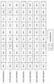
図17は、D2Dリソースの第5の例を説明するための説明図である。図17を参照すると、コンフィギュレーション0〜6が示されている。例えば、コンフィギュレーション0は、6つのアップリンクサブフレームを含む。コンフィギュレーション1は、4つのアップリンクサブフレームを含む。コンフィギュレーション2は、2つのアップリンクサブフレームを含む。コンフィギュレーション3は、3つのアップリンクサブフレームを含む。コンフィギュレーション4は、2つのアップリンクサブフレームを含む。コンフィギュレーション5は、1つのアップリンクサブフレームを含む。コンフィギュレーション6は、5つのアップリンクサブフレームを含む。コンフィギュレーション0、1、6は、多くのアップリンクサブフレーム(例えば、4つ以上のアップリンクサブフレーム)を含むので、コンフィギュレーション0、1、6の各々に適したD2Dリソースは、2つのアップリンクサブフレームの無線リソースである。一方、コンフィギュレーション2、3、4、5は、少ないアップリンクサブフレーム(例えば、3つ以下のアップリンクサブフレーム)を含むので、コンフィギュレーション2、3、4、5の各々に適したD2Dリソースは、1つのアップリンクサブフレームの無線リソースである。 FIG. 17 is an explanatory diagram for describing a fifth example of the D2D resource. Referring to FIG. 17,
これにより、例えば、D2D通信に起因して基地局と端末装置との間のTDDでの無線通信に生じる悪影響を小さくすることが可能になる。より具体的には、例えば、D2D通信によりアップリンクサブフレームがTDDでの無線通信で使用できないとしても、いずれのコンフィギュレーションでも、TDDでの無線通信で使用されるアップリンクサブフレームがある程度確保され得る。そのため、コンフィギュレーションによっては、アップリンクサブフレームがなくなる、又はアップリンクサブフレームの数が激減するという事態が、回避され得る。そのため、アップリンクサブフレームの数が減少することによるアップリンクの通信品質の低下が抑えられ得る。 As a result, for example, it is possible to reduce adverse effects caused in TDD wireless communication between the base station and the terminal device due to D2D communication. More specifically, for example, even if an uplink subframe cannot be used for TDD wireless communication by D2D communication, an uplink subframe used for TDD wireless communication is secured to some extent in any configuration. obtain. Therefore, depending on the configuration, a situation in which the uplink subframe is lost or the number of uplink subframes is drastically reduced can be avoided. Therefore, a decrease in uplink communication quality due to a decrease in the number of uplink subframes can be suppressed.
−D2D通信の限定
基地局100(制御部153)は、上記UL/DLコンフィギュレーションのアップリンクサブフレームの数が所定数以上である場合に、上記UL/DLコンフィギュレーションに適した上記D2Dリソースを端末装置に通知してもよい。一方、基地局100(制御部153)は、上記UL/DLコンフィギュレーションのアップリンクサブフレームの数が上記所定数未満である場合に、上記UL/DLコンフィギュレーションに適した上記D2Dリソースを端末装置に通知しなくてもよい。-Limitation of D2D communication When the number of uplink subframes in the UL / DL configuration is equal to or greater than a predetermined number, the base station 100 (control unit 153) determines the D2D resource suitable for the UL / DL configuration. You may notify a terminal device. On the other hand, when the number of uplink subframes of the UL / DL configuration is less than the predetermined number, the base station 100 (control unit 153) allocates the D2D resource suitable for the UL / DL configuration to a terminal device. You do not have to notify
即ち、上記UL/DLコンフィギュレーションのアップリンクサブフレームの数が上記所定数以上である場合に、D2D通信が行われてもよく、当該アップリンクサブフレームの数が上記所定数未満である場合に、D2D通信が行われなくてもよい。 That is, D2D communication may be performed when the number of uplink subframes in the UL / DL configuration is equal to or greater than the predetermined number, and when the number of uplink subframes is less than the predetermined number. D2D communication may not be performed.
一例として、上記所定数が3であってもよい。この場合に、上記UL/DLコンフィギュレーションが、コンフィギュレーション0、1、3、6のいずれかである場合に、基地局100(制御部153)は、上記UL/DLコンフィギュレーションに適した上記D2Dリソースを端末装置に通知してもよい。一方、上記UL/DLコンフィギュレーションが、コンフィギュレーション2、4、5のいずれかである場合に、基地局100(制御部153)は、上記UL/DLコンフィギュレーションに適した上記D2Dリソースを端末装置に通知しなくてもよい。即ち、上記UL/DLコンフィギュレーションが、コンフィギュレーション0、1、3、6のいずれかである場合には、D2D通信が行われてもよく、上記UL/DLコンフィギュレーションが、コンフィギュレーション2、4、5のいずれかである場合には、D2D通信が行われなくてもよい。 As an example, the predetermined number may be three. In this case, when the UL / DL configuration is any one of
別の例として、上記所定数が2であってもよい。この場合に、上記UL/DLコンフィギュレーションが、コンフィギュレーション0、1、2、3、4、6のいずれかである場合に、基地局100(制御部153)は、上記UL/DLコンフィギュレーションに適した上記D2Dリソースを端末装置に通知してもよい。一方、上記UL/DLコンフィギュレーションが、コンフィギュレーション5である場合に、基地局100(制御部153)は、上記UL/DLコンフィギュレーションに適した上記D2Dリソースを端末装置に通知しなくてもよい。即ち、上記UL/DLコンフィギュレーションが、コンフィギュレーション0、1、2、3、4、6のいずれかである場合には、D2D通信が行われてもよく、上記UL/DLコンフィギュレーションが、コンフィギュレーション5である場合には、D2D通信が行われなくてもよい。 As another example, the predetermined number may be two. In this case, when the UL / DL configuration is any one of
これにより、例えば、コンフィギュレーションのアップリンクサブフレームの数が少ないにもかかわらず、D2D通信によりアップリンクサブフレームがTDDでの無線通信で使用できなくなることを、回避することが可能になる。 As a result, for example, it is possible to avoid that the uplink subframe cannot be used in the wireless communication by TDD due to the D2D communication even though the number of the uplink subframes in the configuration is small.
−コンフィギュレーションの限定
あるいは、上記UL/DLコンフィギュレーションは、所定数以上のアップリンクサブフレームを含むコンフィギュレーションであってもよい。-Limitation of configuration Alternatively, the UL / DL configuration may be a configuration including a predetermined number or more of uplink subframes.
一例として、上記所定数が3であってもよい。この場合に、上記TDDキャリアの上記UL/DLコンフィギュレーションは、コンフィギュレーション0、1、3、6のいずれかであってもよい。即ち、アップリンクサブフレームの数が3未満であるコンフィギュレーション2、4、5が除外されてもよい。 As an example, the predetermined number may be three. In this case, the UL / DL configuration of the TDD carrier may be any one of
別の例として、上記所定数が2であってもよい。この場合に、上記TDDキャリアの上記UL/DLコンフィギュレーションは、コンフィギュレーション0、1、2、3、4、6のいずれかであってもよい。即ち、アップリンクサブフレームの数が2未満であるコンフィギュレーション5が除外されてもよい。 As another example, the predetermined number may be two. In this case, the UL / DL configuration of the TDD carrier may be any one of
これにより、例えば、コンフィギュレーションのアップリンクサブフレームの数が少ないにもかかわらず、D2D通信によりアップリンクサブフレームがTDDでの無線通信で使用できなくなることを、回避することが可能になる。 As a result, for example, it is possible to avoid that the uplink subframe cannot be used in the wireless communication by TDD due to the D2D communication even though the number of the uplink subframes in the configuration is small.
(b)周期に関する特徴
上記UL/DLコンフィギュレーションに適した上記D2Dリソースは、上記UL/DLコンフィギュレーションのアップリンクサブフレームの数に応じた周期で反復する周期的な無線リソースであってもよい。(B) Characteristics related to period The D2D resource suitable for the UL / DL configuration may be a periodic radio resource that repeats at a period corresponding to the number of uplink subframes of the UL / DL configuration. .
(b−1)第1の例
上記UL/DLコンフィギュレーションのアップリンクサブフレームの数がより大きい場合に、上記UL/DLコンフィギュレーションに適した上記D2Dリソースの周期が、より短くてもよい。以下、図18を参照して、コンフィギュレーションごとの周期の具体例を説明する。(B-1) First Example When the number of uplink subframes in the UL / DL configuration is larger, the period of the D2D resource suitable for the UL / DL configuration may be shorter. Hereinafter, a specific example of the period for each configuration will be described with reference to FIG.
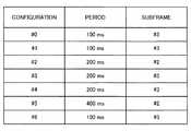
図18は、コンフィギュレーションごとの周期の第1の例を説明するための説明図である。図18を参照すると、7つのコンフィギュレーション(コンフィギュレーション0〜6)の各々の周期及びサブフレームが示されている。この例では、図12に示される例と同様に、各コンフィギュレーション適したD2Dリソースは、1つのアップリンクサブフレームの無線リソースである。例えば、コンフィギュレーション0、1、6は、4つ以上のアップリンクサブフレームを含み、コンフィギュレーション0、1、6に適したD2Dリソースの周期は、100ms(即ち、10無線フレーム)である。コンフィギュレーション2、3、4は、2つ又は3つのアップリンクサブフレームを含み、コンフィギュレーション0、1、6に適したD2Dリソースの周期は、200ms(即ち、20無線フレーム)である。コンフィギュレーション5は、1つのアップリンクサブフレームを含み、コンフィギュレーション5に適したD2Dリソースの周期は、400ms(即ち、40無線フレーム)である。
FIG. 18 is an explanatory diagram for describing a first example of a period for each configuration. Referring to FIG. 18, the period and subframe of each of the seven configurations (
これにより、例えば、コンフィギュレーションのアップリンクサブフレームの数が多いほど、より多くのD2Dリソース(より短い周期のD2Dリソース)が確保される。そのため、基地局と端末装置との間のTDDでの無線通信への影響を抑えつつ、可能な限り多くのD2Dリソースが確保され得る。 Thereby, for example, as the number of uplink subframes in the configuration increases, more D2D resources (D2D resources having a shorter period) are secured. Therefore, as much D2D resources as possible can be secured while suppressing the influence on TDD wireless communication between the base station and the terminal device.
(b−2)第2の例
上記UL/DLコンフィギュレーションに適した上記D2Dリソースは、上記UL/DLコンフィギュレーションが第1のコンフィギュレーションである場合に、第1の数のアップリンクサブフレームの無線リソースであり、且つ第1の周期で反復する周期的な無線リソースであってもよい。一方、上記UL/DLコンフィギュレーションに適した上記D2Dリソースは、上記UL/DLコンフィギュレーションが第2のコンフィギュレーションである場合に、上記第1の数よりも小さい第2の数のアップリンクサブフレームの無線リソースであり、且つ上記第1の周期よりも短い第2の周期で反復する周期的な無線リソースであってもよい。(B-2) Second Example The D2D resource suitable for the UL / DL configuration is the first number of uplink subframes when the UL / DL configuration is the first configuration. It may be a periodic radio resource that is a radio resource and repeats in the first period. On the other hand, the D2D resource suitable for the UL / DL configuration includes a second number of uplink subframes smaller than the first number when the UL / DL configuration is a second configuration. The wireless resource may be a periodic wireless resource that repeats in a second period shorter than the first period.
即ち、上記D2Dリソースは、より多くのアップリンクサブフレームの無線リソースであれば、より長い周期を有し、より少ないアップリンクサブフレームの無線リソースであれば、より短い周期を有する。以下、図19を参照して、コンフィギュレーションごとの周期の具体例を説明する。 That is, the D2D resource has a longer period if it is a radio resource of more uplink subframes, and has a shorter period if it is a radio resource of fewer uplink subframes. Hereinafter, a specific example of the period for each configuration will be described with reference to FIG.
図19は、コンフィギュレーションごとの周期の第2の例を説明するための説明図である。図19を参照すると、7つのコンフィギュレーション(コンフィギュレーション0〜6)の各々の周期及びサブフレームが示されている。例えば、コンフィギュレーション0、1、6は、4つ以上のアップリンクサブフレームを含み、コンフィギュレーション0、1、6の各々に適したD2Dリソースは、2つのアップリンクサブフレームの無線リソースであり、400ms(即ち、40無線フレーム)の周期を有する。また、コンフィギュレーション2、3、4、5は、3つ以下のアップリンクサブフレームを含み、コンフィギュレーション2、3、4、5の各々に適したD2Dリソースは、1つのアップリンクサブフレームの無線リソースであり、200ms(即ち、20無線フレーム)の周期を有する。
FIG. 19 is an explanatory diagram for describing a second example of the period for each configuration. Referring to FIG. 19, the period and subframe of each of the seven configurations (
これにより、例えば、コンフィギュレーションのアップリンクサブフレームの数が少なければ、D2Dリソースは、無線フレームの中の少ないアップリンクサブフレームの無線リソースとなるが、短い周期を有する。そのため、個々の無線フレームにおいて、基地局と端末装置との間のTDDでの無線通信への影響が抑えられつつ、コンフィギュレーション間でのD2Dリソースの量の格差が小さくなり得る。 Thus, for example, if the number of uplink subframes in the configuration is small, the D2D resource becomes a radio resource of a small number of uplink subframes in the radio frame, but has a short period. Therefore, in each radio frame, the influence on the TDD radio communication between the base station and the terminal device can be suppressed, and the difference in the amount of D2D resources between configurations can be reduced.
<<6.処理の流れ>>
続いて、図20〜図22を参照して、本開示の実施形態に係る処理の例を説明する。<< 6. Process flow >>
Next, an example of processing according to an embodiment of the present disclosure will be described with reference to FIGS.
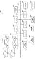
(第1の例)
図20は、本開示の実施形態に係る処理の概略的な流れの第1の例を示すシーケンス図である。(First example)
FIG. 20 is a sequence diagram illustrating a first example of a schematic flow of a process according to the embodiment of the present disclosure.
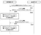
基地局100は、TDDキャリアのUL/DLコンフィギュレーションとして第1のコンフィギュレーションを示すシステム情報を報知する(S401)。また、基地局100は、上記第1のコンフィギュレーションに適したD2Dリソースを示すシステム情報を報知する(S403)。 The
端末装置200は、基地局100が端末装置200に通知する上記D2Dリソース(即ち、上記第1のコンフィギュレーションに適したD2Dリソース)を使用して、D2D通信を行う(S405)。 The
その後、基地局100は、上記TDDキャリアの上記UL/DLコンフィギュレーションを上記第1のコンフィギュレーションから第2のコンフィギュレーションに変更することを決定し、上記UL/DLコンフィギュレーションとして第2のコンフィギュレーションを示すシステム情報を報知する(S407)。また、基地局100は、上記第2のコンフィギュレーションに適したD2Dリソースを示すシステム情報を報知する(S409)。 After that, the
端末装置200は、基地局100が端末装置200に通知する上記D2Dリソース(即ち、上記第2のコンフィギュレーションに適したD2Dリソース)を使用して、D2D通信を行う(S411)。 The
(第2の例)
図21は、本開示の実施形態に係る処理の概略的な流れの第2の例を示すシーケンス図である。(Second example)
FIG. 21 is a sequence diagram illustrating a second example of a schematic flow of a process according to the embodiment of the present disclosure.
基地局100は、TDDキャリアのUL/DLコンフィギュレーションとして第1のコンフィギュレーションを示すシステム情報を報知する(S421)。また、基地局100は、複数のコンフィギュレーションの各々に適したD2Dリソースを示すシステム情報を報知する(S423)。とりわけ、この例では、基地局100は、上記複数のコンフィギュレーションに含まれるコンフィギュレーションごとのD2Dリソースを示すシステム情報を報知する。 The
端末装置200は、上記複数のコンフィギュレーションの各々に適したD2Dリソースのうちの、上記第1のコンフィギュレーションに適したD2Dリソースを使用して、D2D通信を行う(S425)。 The
その後、基地局100は、上記TDDキャリアの上記UL/DLコンフィギュレーションを上記第1のコンフィギュレーションから第2のコンフィギュレーションに変更することを決定し、上記UL/DLコンフィギュレーションとして第2のコンフィギュレーションを示すシステム情報を報知する(S427)。 After that, the
端末装置200は、上記複数のコンフィギュレーションの各々に適したD2Dリソースのうちの、上記第2のコンフィギュレーションに適したD2Dリソースを使用して、D2D通信を行う(S429)。 The
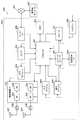
(第3の例)
図22は、本開示の実施形態に係る処理の概略的な流れの第3の例を示すシーケンス図である。(Third example)
FIG. 22 is a sequence diagram illustrating a third example of a schematic flow of a process according to the embodiment of the present disclosure.
基地局100は、TDDキャリアのUL/DLコンフィギュレーションとして第1のコンフィギュレーションを示すシステム情報を報知する(S441)。また、基地局100は、複数のコンフィギュレーションの各々に適したD2Dリソースを示すシステム情報を報知する(S443)。とりわけ、この例では、基地局100は、上記複数のコンフィギュレーションの間で共通するアップリンクサブフレームの無線リソースを示すシステム情報を報知する。さらに、例えば、当該無線リソースは、上記複数のコンフィギュレーション間で共通するD2Dリソース(即ち、サブフレーム、周期及びオフセットが上記複数のコンフィギュレーションの間で共通であるD2Dリソース)である。 The
端末装置200は、基地局100が端末装置200に通知する上記D2Dリソース(即ち、上記複数のコンフィギュレーション間で共通するD2Dリソース)を使用して、D2D通信を行う(S445)。 The
なお、例えば、その後、基地局100が、上記TDDキャリアの上記UL/DLコンフィギュレーションを上記第1のコンフィギュレーションから第2のコンフィギュレーションに変更する。端末装置200は、この変更によらず、上記D2Dリソース(即ち、上記複数のコンフィギュレーション間で共通するD2Dリソース)を引き続き使用して、D2D通信を行う。 For example, after that, the
<<7.応用例>>
本開示に係る技術は、様々な製品へ応用可能である。基地局100は、マクロeNB又はスモールeNBなどのいずれかの種類のeNB(evolved Node B)として実現されてもよい。スモールeNBは、ピコeNB、マイクロeNB又はホーム(フェムト)eNBなどの、マクロセルよりも小さいセルをカバーするeNBであってよい。その代わりに、基地局100は、NodeB又はBTS(Base Transceiver Station)などの他の種類の基地局として実現されてもよい。基地局100は、無線通信を制御する本体(基地局装置ともいう)と、本体とは別の場所に配置される1つ以上のRRH(Remote Radio Head)とを含んでもよい。また、後述する様々な種類の端末が一時的に又は半永続的に基地局機能を実行することにより、基地局100として動作してもよい。さらに、基地局100の少なくとも一部の構成要素は、基地局装置又は基地局装置のためのモジュールにおいて実現されてもよい。<< 7. Application example >>
The technology according to the present disclosure can be applied to various products. The
また、例えば、端末装置200は、スマートフォン、タブレットPC(Personal Computer)、ノートPC、携帯型ゲーム端末、携帯型/ドングル型のモバイルルータ若しくはデジタルカメラなどのモバイル端末、又はカーナビゲーション装置などの車載端末として実現されてもよい。また、端末装置200は、M2M(Machine To Machine)通信を行う端末(MTC(Machine Type Communication)端末ともいう)として実現されてもよい。さらに、端末装置200の少なくとも一部の構成要素は、これら端末に搭載されるモジュール(例えば、1つのダイで構成される集積回路モジュール)において実現されてもよい。 Further, for example, the
<7.1.基地局に関する応用例>
(第1の応用例)
図23は、本開示に係る技術が適用され得るeNBの概略的な構成の第1の例を示すブロック図である。eNB800は、1つ以上のアンテナ810、及び基地局装置820を有する。各アンテナ810及び基地局装置820は、RFケーブルを介して互いに接続され得る。<7.1. Application examples for base stations>
(First application example)
FIG. 23 is a block diagram illustrating a first example of a schematic configuration of an eNB to which the technology according to the present disclosure may be applied. The
アンテナ810の各々は、単一の又は複数のアンテナ素子(例えば、MIMOアンテナを構成する複数のアンテナ素子)を有し、基地局装置820による無線信号の送受信のために使用される。eNB800は、図23に示したように複数のアンテナ810を有し、複数のアンテナ810は、例えばeNB800が使用する複数の周波数帯域にそれぞれ対応してもよい。なお、図23にはeNB800が複数のアンテナ810を有する例を示したが、eNB800は単一のアンテナ810を有してもよい。 Each of the
基地局装置820は、コントローラ821、メモリ822、ネットワークインタフェース823及び無線通信インタフェース825を備える。 The
コントローラ821は、例えばCPU又はDSPであってよく、基地局装置820の上位レイヤの様々な機能を動作させる。例えば、コントローラ821は、無線通信インタフェース825により処理された信号内のデータからデータパケットを生成し、生成したパケットをネットワークインタフェース823を介して転送する。コントローラ821は、複数のベースバンドプロセッサからのデータをバンドリングすることによりバンドルドパケットを生成し、生成したバンドルドパケットを転送してもよい。また、コントローラ821は、無線リソース管理(Radio Resource Control)、無線ベアラ制御(Radio Bearer Control)、移動性管理(Mobility Management)、流入制御(Admission Control)又はスケジューリング(Scheduling)などの制御を実行する論理的な機能を有してもよい。また、当該制御は、周辺のeNB又はコアネットワークノードと連携して実行されてもよい。メモリ822は、RAM及びROMを含み、コントローラ821により実行されるプログラム、及び様々な制御データ(例えば、端末リスト、送信電力データ及びスケジューリングデータなど)を記憶する。 The
ネットワークインタフェース823は、基地局装置820をコアネットワーク824に接続するための通信インタフェースである。コントローラ821は、ネットワークインタフェース823を介して、コアネットワークノード又は他のeNBと通信してもよい。その場合に、eNB800と、コアネットワークノード又は他のeNBとは、論理的なインタフェース(例えば、S1インタフェース又はX2インタフェース)により互いに接続されてもよい。ネットワークインタフェース823は、有線通信インタフェースであってもよく、又は無線バックホールのための無線通信インタフェースであってもよい。ネットワークインタフェース823が無線通信インタフェースである場合、ネットワークインタフェース823は、無線通信インタフェース825により使用される周波数帯域よりもより高い周波数帯域を無線通信に使用してもよい。 The
無線通信インタフェース825は、LTE(Long Term Evolution)又はLTE−Advancedなどのいずれかのセルラー通信方式をサポートし、アンテナ810を介して、eNB800のセル内に位置する端末に無線接続を提供する。無線通信インタフェース825は、典型的には、ベースバンド(BB)プロセッサ826及びRF回路827などを含み得る。BBプロセッサ826は、例えば、符号化/復号、変調/復調及び多重化/逆多重化などを行なってよく、各レイヤ(例えば、L1、MAC(Medium Access Control)、RLC(Radio Link Control)及びPDCP(Packet Data Convergence Protocol))の様々な信号処理を実行する。BBプロセッサ826は、コントローラ821の代わりに、上述した論理的な機能の一部又は全部を有してもよい。BBプロセッサ826は、通信制御プログラムを記憶するメモリ、当該プログラムを実行するプロセッサ及び関連する回路を含むモジュールであってもよく、BBプロセッサ826の機能は、上記プログラムのアップデートにより変更可能であってもよい。また、上記モジュールは、基地局装置820のスロットに挿入されるカード若しくはブレードであってもよく、又は上記カード若しくは上記ブレードに搭載されるチップであってもよい。一方、RF回路827は、ミキサ、フィルタ及びアンプなどを含んでもよく、アンテナ810を介して無線信号を送受信する。 The
無線通信インタフェース825は、図23に示したように複数のBBプロセッサ826を含み、複数のBBプロセッサ826は、例えばeNB800が使用する複数の周波数帯域にそれぞれ対応してもよい。また、無線通信インタフェース825は、図23に示したように複数のRF回路827を含み、複数のRF回路827は、例えば複数のアンテナ素子にそれぞれ対応してもよい。なお、図23には無線通信インタフェース825が複数のBBプロセッサ826及び複数のRF回路827を含む例を示したが、無線通信インタフェース825は単一のBBプロセッサ826又は単一のRF回路827を含んでもよい。 The
図23に示したeNB800において、図10を参照して説明した制御部153(及び情報取得部151)は、無線通信インタフェース825において実装されてもよい。あるいは、これらの構成要素の少なくとも一部は、コントローラ821において実装されてもよい。一例として、eNB800は、無線通信インタフェース825の一部(例えば、BBプロセッサ826)若しくは全部、及び/又はコントローラ821を含むモジュールを搭載し、当該モジュールにおいて制御部153(及び情報取得部151)が実装されてもよい。この場合に、上記モジュールは、プロセッサを制御部153(及び情報取得部151)として機能させるためのプログラム(換言すると、プロセッサに制御部153(及び情報取得部151)の動作を実行させるためのプログラム)を記憶し、当該プログラムを実行してもよい。別の例として、プロセッサを制御部153(及び情報取得部151)として機能させるためのプログラムがeNB800にインストールされ、無線通信インタフェース825(例えば、BBプロセッサ826)及び/又はコントローラ821が当該プログラムを実行してもよい。以上のように、制御部153(及び情報取得部151)を備える装置としてeNB800、基地局装置820又は上記モジュールが提供されてもよく、プロセッサを制御部153(及び情報取得部151)として機能させるためのプログラムが提供されてもよい。また、上記プログラムを記録した読み取り可能な記録媒体が提供されてもよい。 In the
また、図23に示したeNB800において、図10を参照して説明した無線通信部120は、無線通信インタフェース825(例えば、RF回路827)において実装されてもよい。また、アンテナ部110は、アンテナ810において実装されてもよい。また、ネットワーク通信部130は、コントローラ821及び/又はネットワークインタフェース823において実装されてもよい。 In the
(第2の応用例)
図24は、本開示に係る技術が適用され得るeNBの概略的な構成の第2の例を示すブロック図である。eNB830は、1つ以上のアンテナ840、基地局装置850、及びRRH860を有する。各アンテナ840及びRRH860は、RFケーブルを介して互いに接続され得る。また、基地局装置850及びRRH860は、光ファイバケーブルなどの高速回線で互いに接続され得る。(Second application example)
FIG. 24 is a block diagram illustrating a second example of a schematic configuration of an eNB to which the technology according to the present disclosure may be applied. The
アンテナ840の各々は、単一の又は複数のアンテナ素子(例えば、MIMOアンテナを構成する複数のアンテナ素子)を有し、RRH860による無線信号の送受信のために使用される。eNB830は、図24に示したように複数のアンテナ840を有し、複数のアンテナ840は、例えばeNB830が使用する複数の周波数帯域にそれぞれ対応してもよい。なお、図24にはeNB830が複数のアンテナ840を有する例を示したが、eNB830は単一のアンテナ840を有してもよい。 Each of the
基地局装置850は、コントローラ851、メモリ852、ネットワークインタフェース853、無線通信インタフェース855及び接続インタフェース857を備える。コントローラ851、メモリ852及びネットワークインタフェース853は、図23を参照して説明したコントローラ821、メモリ822及びネットワークインタフェース823と同様のものである。 The
無線通信インタフェース855は、LTE又はLTE−Advancedなどのいずれかのセルラー通信方式をサポートし、RRH860及びアンテナ840を介して、RRH860に対応するセクタ内に位置する端末に無線接続を提供する。無線通信インタフェース855は、典型的には、BBプロセッサ856などを含み得る。BBプロセッサ856は、接続インタフェース857を介してRRH860のRF回路864と接続されることを除き、図23を参照して説明したBBプロセッサ826と同様のものである。無線通信インタフェース855は、図24に示したように複数のBBプロセッサ856を含み、複数のBBプロセッサ856は、例えばeNB830が使用する複数の周波数帯域にそれぞれ対応してもよい。なお、図24には無線通信インタフェース855が複数のBBプロセッサ856を含む例を示したが、無線通信インタフェース855は単一のBBプロセッサ856を含んでもよい。 The
接続インタフェース857は、基地局装置850(無線通信インタフェース855)をRRH860と接続するためのインタフェースである。接続インタフェース857は、基地局装置850(無線通信インタフェース855)とRRH860とを接続する上記高速回線での通信のための通信モジュールであってもよい。 The
また、RRH860は、接続インタフェース861及び無線通信インタフェース863を備える。 The
接続インタフェース861は、RRH860(無線通信インタフェース863)を基地局装置850と接続するためのインタフェースである。接続インタフェース861は、上記高速回線での通信のための通信モジュールであってもよい。 The
無線通信インタフェース863は、アンテナ840を介して無線信号を送受信する。無線通信インタフェース863は、典型的には、RF回路864などを含み得る。RF回路864は、ミキサ、フィルタ及びアンプなどを含んでもよく、アンテナ840を介して無線信号を送受信する。無線通信インタフェース863は、図24に示したように複数のRF回路864を含み、複数のRF回路864は、例えば複数のアンテナ素子にそれぞれ対応してもよい。なお、図24には無線通信インタフェース863が複数のRF回路864を含む例を示したが、無線通信インタフェース863は単一のRF回路864を含んでもよい。 The
図24に示したeNB830において、図10を参照して説明した制御部153(及び情報取得部151)は、無線通信インタフェース855及び/又は無線通信インタフェース863において実装されてもよい。あるいは、これらの構成要素の少なくとも一部は、コントローラ851において実装されてもよい。一例として、eNB830は、無線通信インタフェース855の一部(例えば、BBプロセッサ856)若しくは全部、及び/又はコントローラ851を含むモジュールを搭載し、当該モジュールにおいて制御部153(及び情報取得部151)が実装されてもよい。この場合に、上記モジュールは、プロセッサを制御部153(及び情報取得部151)として機能させるためのプログラム(換言すると、プロセッサに制御部153(及び情報取得部151)の動作を実行させるためのプログラム)を記憶し、当該プログラムを実行してもよい。別の例として、プロセッサを制御部153(及び情報取得部151)として機能させるためのプログラムがeNB830にインストールされ、無線通信インタフェース855(例えば、BBプロセッサ856)及び/又はコントローラ851が当該プログラムを実行してもよい。以上のように、制御部153(及び情報取得部151)を備える装置としてeNB830、基地局装置850又は上記モジュールが提供されてもよく、プロセッサを制御部153(及び情報取得部151)として機能させるためのプログラムが提供されてもよい。また、上記プログラムを記録した読み取り可能な記録媒体が提供されてもよい。 In the
また、図24に示したeNB830において、例えば、図10を参照して説明した無線通信部120は、無線通信インタフェース863(例えば、RF回路864)において実装されてもよい。また、アンテナ部110は、アンテナ840において実装されてもよい。また、ネットワーク通信部130は、コントローラ851及び/又はネットワークインタフェース853において実装されてもよい。 In the
<7.2.端末装置に関する応用例>
(第1の応用例)
図25は、本開示に係る技術が適用され得るスマートフォン900の概略的な構成の一例を示すブロック図である。スマートフォン900は、プロセッサ901、メモリ902、ストレージ903、外部接続インタフェース904、カメラ906、センサ907、マイクロフォン908、入力デバイス909、表示デバイス910、スピーカ911、無線通信インタフェース912、1つ以上のアンテナスイッチ915、1つ以上のアンテナ916、バス917、バッテリー918及び補助コントローラ919を備える。<7.2. Application examples related to terminal devices>
(First application example)
FIG. 25 is a block diagram illustrating an example of a schematic configuration of a
プロセッサ901は、例えばCPU又はSoC(System on Chip)であってよく、スマートフォン900のアプリケーションレイヤ及びその他のレイヤの機能を制御する。メモリ902は、RAM及びROMを含み、プロセッサ901により実行されるプログラム及びデータを記憶する。ストレージ903は、半導体メモリ又はハードディスクなどの記憶媒体を含み得る。外部接続インタフェース904は、メモリーカード又はUSB(Universal Serial Bus)デバイスなどの外付けデバイスをスマートフォン900へ接続するためのインタフェースである。 The
カメラ906は、例えば、CCD(Charge Coupled Device)又はCMOS(Complementary Metal Oxide Semiconductor)などの撮像素子を有し、撮像画像を生成する。センサ907は、例えば、測位センサ、ジャイロセンサ、地磁気センサ及び加速度センサなどのセンサ群を含み得る。マイクロフォン908は、スマートフォン900へ入力される音声を音声信号へ変換する。入力デバイス909は、例えば、表示デバイス910の画面上へのタッチを検出するタッチセンサ、キーパッド、キーボード、ボタン又はスイッチなどを含み、ユーザからの操作又は情報入力を受け付ける。表示デバイス910は、液晶ディスプレイ(LCD)又は有機発光ダイオード(OLED)ディスプレイなどの画面を有し、スマートフォン900の出力画像を表示する。スピーカ911は、スマートフォン900から出力される音声信号を音声に変換する。 The
無線通信インタフェース912は、LTE又はLTE−Advancedなどのいずれかのセルラー通信方式をサポートし、無線通信を実行する。無線通信インタフェース912は、典型的には、BBプロセッサ913及びRF回路914などを含み得る。BBプロセッサ913は、例えば、符号化/復号、変調/復調及び多重化/逆多重化などを行なってよく、無線通信のための様々な信号処理を実行する。一方、RF回路914は、ミキサ、フィルタ及びアンプなどを含んでもよく、アンテナ916を介して無線信号を送受信する。無線通信インタフェース912は、BBプロセッサ913及びRF回路914を集積したワンチップのモジュールであってもよい。無線通信インタフェース912は、図25に示したように複数のBBプロセッサ913及び複数のRF回路914を含んでもよい。なお、図25には無線通信インタフェース912が複数のBBプロセッサ913及び複数のRF回路914を含む例を示したが、無線通信インタフェース912は単一のBBプロセッサ913又は単一のRF回路914を含んでもよい。 The
さらに、無線通信インタフェース912は、セルラー通信方式に加えて、近距離無線通信方式、近接無線通信方式又は無線LAN(Local Area Network)方式などの他の種類の無線通信方式をサポートしてもよく、その場合に、無線通信方式ごとのBBプロセッサ913及びRF回路914を含んでもよい。 Furthermore, in addition to the cellular communication method, the
アンテナスイッチ915の各々は、無線通信インタフェース912に含まれる複数の回路(例えば、異なる無線通信方式のための回路)の間でアンテナ916の接続先を切り替える。 Each of the
アンテナ916の各々は、単一の又は複数のアンテナ素子(例えば、MIMOアンテナを構成する複数のアンテナ素子)を有し、無線通信インタフェース912による無線信号の送受信のために使用される。スマートフォン900は、図25に示したように複数のアンテナ916を有してもよい。なお、図25にはスマートフォン900が複数のアンテナ916を有する例を示したが、スマートフォン900は単一のアンテナ916を有してもよい。 Each of the
さらに、スマートフォン900は、無線通信方式ごとにアンテナ916を備えてもよい。その場合に、アンテナスイッチ915は、スマートフォン900の構成から省略されてもよい。 Furthermore, the
バス917は、プロセッサ901、メモリ902、ストレージ903、外部接続インタフェース904、カメラ906、センサ907、マイクロフォン908、入力デバイス909、表示デバイス910、スピーカ911、無線通信インタフェース912及び補助コントローラ919を互いに接続する。バッテリー918は、図中に破線で部分的に示した給電ラインを介して、図25に示したスマートフォン900の各ブロックへ電力を供給する。補助コントローラ919は、例えば、スリープモードにおいて、スマートフォン900の必要最低限の機能を動作させる。 The
図25に示したスマートフォン900において、図11を参照して説明した情報取得部241及び制御部243は、無線通信インタフェース912において実装されてもよい。あるいは、これらの構成要素の少なくとも一部は、プロセッサ901又は補助コントローラ919において実装されてもよい。一例として、スマートフォン900は、無線通信インタフェース912の一部(例えば、BBプロセッサ913)若しくは全部、プロセッサ901、及び/又は補助コントローラ919を含むモジュールを搭載し、当該モジュールにおいて情報取得部241及び制御部243が実装されてもよい。この場合に、上記モジュールは、プロセッサを情報取得部241及び制御部243として機能させるためのプログラム(換言すると、プロセッサに情報取得部241及び制御部243の動作を実行させるためのプログラム)を記憶し、当該プログラムを実行してもよい。別の例として、プロセッサを情報取得部241及び制御部243として機能させるためのプログラムがスマートフォン900にインストールされ、無線通信インタフェース912(例えば、BBプロセッサ913)、プロセッサ901、及び/又は補助コントローラ919が当該プログラムを実行してもよい。以上のように、情報取得部241及び制御部243を備える装置としてスマートフォン900又は上記モジュールが提供されてもよく、プロセッサを情報取得部241及び制御部243として機能させるためのプログラムが提供されてもよい。また、上記プログラムを記録した読み取り可能な記録媒体が提供されてもよい。 In the
また、図25に示したスマートフォン900において、例えば、図11を参照して説明した無線通信部220は、無線通信インタフェース912(例えば、RF回路914)において実装されてもよい。また、アンテナ部210は、アンテナ916において実装されてもよい。 In the
(第2の応用例)
図26は、本開示に係る技術が適用され得るカーナビゲーション装置920の概略的な構成の一例を示すブロック図である。カーナビゲーション装置920は、プロセッサ921、メモリ922、GPS(Global Positioning System)モジュール924、センサ925、データインタフェース926、コンテンツプレーヤ927、記憶媒体インタフェース928、入力デバイス929、表示デバイス930、スピーカ931、無線通信インタフェース933、1つ以上のアンテナスイッチ936、1つ以上のアンテナ937及びバッテリー938を備える。(Second application example)
FIG. 26 is a block diagram illustrating an example of a schematic configuration of a
プロセッサ921は、例えばCPU又はSoCであってよく、カーナビゲーション装置920のナビゲーション機能及びその他の機能を制御する。メモリ922は、RAM及びROMを含み、プロセッサ921により実行されるプログラム及びデータを記憶する。 The
GPSモジュール924は、GPS衛星から受信されるGPS信号を用いて、カーナビゲーション装置920の位置(例えば、緯度、経度及び高度)を測定する。センサ925は、例えば、ジャイロセンサ、地磁気センサ及び気圧センサなどのセンサ群を含み得る。データインタフェース926は、例えば、図示しない端子を介して車載ネットワーク941に接続され、車速データなどの車両側で生成されるデータを取得する。 The
コンテンツプレーヤ927は、記憶媒体インタフェース928に挿入される記憶媒体(例えば、CD又はDVD)に記憶されているコンテンツを再生する。入力デバイス929は、例えば、表示デバイス930の画面上へのタッチを検出するタッチセンサ、ボタン又はスイッチなどを含み、ユーザからの操作又は情報入力を受け付ける。表示デバイス930は、LCD又はOLEDディスプレイなどの画面を有し、ナビゲーション機能又は再生されるコンテンツの画像を表示する。スピーカ931は、ナビゲーション機能又は再生されるコンテンツの音声を出力する。 The
無線通信インタフェース933は、LTE又はLTE−Advancedなどのいずれかのセルラー通信方式をサポートし、無線通信を実行する。無線通信インタフェース933は、典型的には、BBプロセッサ934及びRF回路935などを含み得る。BBプロセッサ934は、例えば、符号化/復号、変調/復調及び多重化/逆多重化などを行なってよく、無線通信のための様々な信号処理を実行する。一方、RF回路935は、ミキサ、フィルタ及びアンプなどを含んでもよく、アンテナ937を介して無線信号を送受信する。無線通信インタフェース933は、BBプロセッサ934及びRF回路935を集積したワンチップのモジュールであってもよい。無線通信インタフェース933は、図26に示したように複数のBBプロセッサ934及び複数のRF回路935を含んでもよい。なお、図26には無線通信インタフェース933が複数のBBプロセッサ934及び複数のRF回路935を含む例を示したが、無線通信インタフェース933は単一のBBプロセッサ934又は単一のRF回路935を含んでもよい。 The
さらに、無線通信インタフェース933は、セルラー通信方式に加えて、近距離無線通信方式、近接無線通信方式又は無線LAN方式などの他の種類の無線通信方式をサポートしてもよく、その場合に、無線通信方式ごとのBBプロセッサ934及びRF回路935を含んでもよい。 Further, the
アンテナスイッチ936の各々は、無線通信インタフェース933に含まれる複数の回路(例えば、異なる無線通信方式のための回路)の間でアンテナ937の接続先を切り替える。 Each of the
アンテナ937の各々は、単一の又は複数のアンテナ素子(例えば、MIMOアンテナを構成する複数のアンテナ素子)を有し、無線通信インタフェース933による無線信号の送受信のために使用される。カーナビゲーション装置920は、図26に示したように複数のアンテナ937を有してもよい。なお、図26にはカーナビゲーション装置920が複数のアンテナ937を有する例を示したが、カーナビゲーション装置920は単一のアンテナ937を有してもよい。 Each of the
さらに、カーナビゲーション装置920は、無線通信方式ごとにアンテナ937を備えてもよい。その場合に、アンテナスイッチ936は、カーナビゲーション装置920の構成から省略されてもよい。 Furthermore, the
バッテリー938は、図中に破線で部分的に示した給電ラインを介して、図26に示したカーナビゲーション装置920の各ブロックへ電力を供給する。また、バッテリー938は、車両側から給電される電力を蓄積する。 The
図26に示したカーナビゲーション装置920において、図11を参照して説明した情報取得部241及び制御部243は、無線通信インタフェース933において実装されてもよい。あるいは、これらの構成要素の少なくとも一部は、プロセッサ921において実装されてもよい。一例として、カーナビゲーション装置920は、無線通信インタフェース933の一部(例えば、BBプロセッサ934)若しくは全部及び/又はプロセッサ921を含むモジュールを搭載し、当該モジュールにおいて情報取得部241及び制御部243が実装されてもよい。この場合に、上記モジュールは、プロセッサを情報取得部241及び制御部243として機能させるためのプログラム(換言すると、プロセッサに情報取得部241及び制御部243の動作を実行させるためのプログラム)を記憶し、当該プログラムを実行してもよい。別の例として、プロセッサを情報取得部241及び制御部243として機能させるためのプログラムがカーナビゲーション装置920にインストールされ、無線通信インタフェース933(例えば、BBプロセッサ934)及び/又はプロセッサ921が当該プログラムを実行してもよい。以上のように、情報取得部241及び制御部243を備える装置としてカーナビゲーション装置920又は上記モジュールが提供されてもよく、プロセッサを情報取得部241及び制御部243として機能させるためのプログラムが提供されてもよい。また、上記プログラムを記録した読み取り可能な記録媒体が提供されてもよい。 In the
また、図26に示したカーナビゲーション装置920において、例えば、図11を参照して説明した無線通信部220は、無線通信インタフェース933(例えば、RF回路935)において実装されてもよい。また、アンテナ部210は、アンテナ937において実装されてもよい。 In the
また、本開示に係る技術は、上述したカーナビゲーション装置920の1つ以上のブロックと、車載ネットワーク941と、車両側モジュール942とを含む車載システム(又は車両)940として実現されてもよい。即ち、情報取得部241及び制御部243を備える装置として車載システム(又は車両)940が提供されてもよい。車両側モジュール942は、車速、エンジン回転数又は故障情報などの車両側データを生成し、生成したデータを車載ネットワーク941へ出力する。 In addition, the technology according to the present disclosure may be realized as an in-vehicle system (or vehicle) 940 including one or more blocks of the
<<8.まとめ>>
ここまで、図1〜図26を参照して、本開示の実施形態に係る各装置及び各処理などを説明した。<< 8. Summary >>
So far, each device and each process according to the embodiment of the present disclosure have been described with reference to FIGS.
本開示に係る実施形態によれば、基地局100は、TDDキャリアのUL/DLコンフィギュレーションを動的に変更する制御部153を備える。制御部153は、上記UL/DLコンフィギュレーションに適したD2D通信用の無線リソースを端末装置に通知する。上記無線リソースは、上記UL/DLコンフィギュレーションの少なくとも1つのアップリンクサブフレームの無線リソースである。 According to the embodiment according to the present disclosure, the
また、本開示に係る実施形態によれば、基地局100により動的に変更されるTDDキャリアのUL/DLコンフィギュレーションに適したD2D通信用の無線リソースを示す情報を取得する情報取得部241と、上記無線リソースを使用したD2D通信を制御する制御部243と、を備える。上記無線リソースは、上記UL/DLコンフィギュレーションの少なくとも1つのアップリンクサブフレームの無線リソースである。 Further, according to the embodiment of the present disclosure, the
これにより、例えば、TDDの環境下で端末装置が適切にD2D通信を行うことが可能になる。 Thereby, for example, the terminal device can appropriately perform D2D communication in a TDD environment.
以上、添付図面を参照しながら本開示の好適な実施形態を説明したが、本開示は係る例に限定されないことは言うまでもない。当業者であれば、特許請求の範囲に記載された範疇内において、各種の変更例又は修正例に想到し得ることは明らかであり、それらについても当然に本開示の技術的範囲に属するものと了解される。 As mentioned above, although preferred embodiment of this indication was described referring an accompanying drawing, it cannot be overemphasized that this indication is not limited to the example concerned. It will be apparent to those skilled in the art that various changes and modifications can be made within the scope of the claims, and these are naturally within the technical scope of the present disclosure. Understood.
例えば、第1の技術的特徴と第2の技術的特徴を説明したが、第1の技術的特徴と第2の技術的特徴とが組合せられなくてもよい。 For example, although the first technical feature and the second technical feature have been described, the first technical feature and the second technical feature may not be combined.
例えば、第1の技術的特徴が採用され、第2の技術的特徴が採用されなくてもよい。 For example, the first technical feature may be employed and the second technical feature may not be employed.
例えば、第2の技術的特徴が採用され、第1の技術的特徴が採用されなくてもよい。この場合には、TDDキャリアのUL/DLコンフィギュレーションは、動的に変更されなくてもよい。一例として、基地局(情報取得部)は、(動的に変更されない)UL/DLコンフィギュレーションに適したD2Dリソースを示す情報を取得してもよい。そして、基地局(制御部)は、当該D2Dリソースを端末装置に通知してもよい。当該D2Dリソースは、上記UL/DLコンフィギュレーションの少なくとも1つのアップリンクサブフレームの無線リソースであってもよい。そして、当該D2Dリソースには、第2の技術的特徴(即ち、第2の技術的特徴のうちのいずれか)が適用されてもよい。 For example, the second technical feature may be employed, and the first technical feature may not be employed. In this case, the UL / DL configuration of the TDD carrier may not be changed dynamically. As an example, the base station (information acquisition unit) may acquire information indicating a D2D resource suitable for UL / DL configuration (not dynamically changed). And a base station (control part) may notify the said D2D resource to a terminal device. The D2D resource may be a radio resource of at least one uplink subframe of the UL / DL configuration. Then, the second technical feature (that is, one of the second technical features) may be applied to the D2D resource.
また、例えば、通信システムがLTE、LTE−Advanced、又はこれらに準ずる通信規格に準拠したシステムである例を説明したが、本開示は係る例に限定されない。例えば、通信システムは、他の通信規格に準拠したシステムであってもよい。 Further, for example, the communication system has been described as an example in which the communication system is based on LTE, LTE-Advanced, or a communication standard based on these, but the present disclosure is not limited to such an example. For example, the communication system may be a system that complies with other communication standards.
また、本明細書の処理における処理ステップは、必ずしもフローチャート又はシーケンス図に記載された順序に沿って時系列に実行されなくてよい。例えば、処理における処理ステップは、フローチャート又はシーケンス図として記載した順序と異なる順序で実行されても、並列的に実行されてもよい。 Further, the processing steps in the processing of the present specification do not necessarily have to be executed in time series in the order described in the flowchart or the sequence diagram. For example, the processing steps in the processing may be executed in an order different from the order described as a flowchart or a sequence diagram, or may be executed in parallel.
また、本明細書の装置(例えば、基地局、基地局のための基地局装置、若しくは当該基地局装置のためのモジュール、又は、端末装置若しくは端末装置のためのモジュール)に備えられるプロセッサ(例えば、CPU、DSPなど)を上記装置の構成要素(例えば、情報取得部及び/又は制御部)として機能させるためのコンピュータプログラム(換言すると、上記プロセッサに上記装置の構成要素の動作を実行させるためのコンピュータプログラム)も作成可能である。また、当該コンピュータプログラムを記録した記録媒体も提供されてもよい。また、上記コンピュータプログラムを記憶するメモリと、上記コンピュータプログラムを実行可能な1つ以上のプロセッサとを備える装置(例えば、完成品、又は完成品のためのモジュール(部品、処理回路若しくはチップなど))も提供されてもよい。また、上記装置の構成要素(例えば、情報取得部及び/又は制御部など)の動作を含む方法も、本開示に係る技術に含まれる。 In addition, a processor (for example, a base station, a base station device for the base station, a module for the base station device, or a terminal device or a module for the terminal device) (for example, a base station, a base station device for the base station) , A CPU, a DSP, etc.) for causing a computer program to function as a component (for example, an information acquisition unit and / or a control unit) of the device (in other words, for causing the processor to execute the operation of the component of the device) Computer programs can also be created. Moreover, a recording medium on which the computer program is recorded may be provided. An apparatus (for example, a finished product or a module for a finished product (a component, a processing circuit, a chip, or the like)) including a memory that stores the computer program and one or more processors that can execute the computer program May also be provided. In addition, a method including the operation of the components of the device (for example, an information acquisition unit and / or a control unit) is also included in the technology according to the present disclosure.
また、本明細書に記載された効果は、あくまで説明的又は例示的なものであって限定的ではない。つまり、本開示に係る技術は、上記効果とともに、又は上記効果に代えて、本明細書の記載から当業者には明らかな他の効果を奏しうる。 In addition, the effects described in the present specification are merely illustrative or illustrative, and are not limited. That is, the technology according to the present disclosure can exhibit other effects that are apparent to those skilled in the art from the description of the present specification in addition to or instead of the above effects.
なお、以下のような構成も本開示の技術的範囲に属する。
(1)
TDD(Time Division Duplex)キャリアのアップリンク/ダウンリンクコンフィギュレーションを動的に変更する制御部、
を備え、
前記制御部は、前記アップリンク/ダウンリンクコンフィギュレーションに適した装置間通信用の無線リソースを端末装置に通知し、
前記無線リソースは、前記アップリンク/ダウンリンクコンフィギュレーションの少なくとも1つのアップリンクサブフレームの無線リソースである、
装置。
(2)
前記制御部は、複数のコンフィギュレーションのうちの1つのコンフィギュレーションから、当該複数のコンフィギュレーションのうちの別のコンフィギュレーションに、前記アップリンク/ダウンリンクコンフィギュレーションを変更する、前記(1)に記載の装置。
(3)
前記制御部は、前記アップリンク/ダウンリンクコンフィギュレーションの変更に応じて、前記別のコンフィギュレーションに適した装置間通信用の無線リソースを端末装置に通知し、
前記別のコンフィギュレーションに適した前記無線リソースは、前記別のコンフィギュレーションの少なくとも1つのアップリンクサブフレームの無線リソースである、
前記(2)に記載の装置。
(4)
前記制御部は、前記複数のコンフィギュレーションの各々に適した装置間通信用の無線リソースを、端末装置に通知する、前記(2)に記載の装置。
(5)
前記複数のコンフィギュレーションの各々に適した前記無線リソースは、コンフィギュレーションごとの装置間通信用の無線リソースを含み、
コンフィギュレーションごとの前記無線リソースは、コンフィギュレーションの少なくとも1つのアップリンクサブフレームの無線リソースである、
前記(4)に記載の装置。
(6)
前記複数のコンフィギュレーションの各々に適した前記無線リソースは、前記複数のコンフィギュレーションの間で共通する少なくとも1つのアップリンクサブフレームの無線リソースである、前記(4)に記載の装置。
(7)
前記少なくとも1つのアップリンクサブフレームに含まれるアップリンクサブフレームの数は、前記アップリンク/ダウンリンクコンフィギュレーションのアップリンクサブフレームの数によって異なる、前記(1)〜(5)のいずれか1項に記載の装置。
(8)
前記無線リソースは、前記アップリンク/ダウンリンクコンフィギュレーションのアップリンクサブフレームの数に応じた周期で反復する周期的な無線リソースである、前記(1)〜(7)のいずれか1項に記載の装置。
(9)
前記無線リソースは、前記アップリンク/ダウンリンクコンフィギュレーションが第1のコンフィギュレーションである場合に、第1の数のアップリンクサブフレームの無線リソースであり、且つ第1の周期で反復する周期的な無線リソースであり、前記アップリンク/ダウンリンクコンフィギュレーションが第2のコンフィギュレーションである場合に、前記第1の数よりも小さい第2の数のアップリンクサブフレームの無線リソースであり、且つ前記第1の周期よりも短い第2の周期で反復する周期的な無線リソースである、前記(1)〜(8)のいずれか1項に記載の装置。
(10)
前記制御部は、前記アップリンク/ダウンリンクコンフィギュレーションのアップリンクサブフレームの数が所定数以上である場合に、前記無線リソースを端末装置に通知する、前記(1)〜(9)のいずれか1項に記載の装置。
(11)
前記アップリンク/ダウンリンクコンフィギュレーションは、所定数以上のアップリンクサブフレームを含むコンフィギュレーションである、前記(1)〜(9)のいずれか1項に記載の装置。
(12)
前記少なくとも1つのアップリンクサブフレームの各々は、前記アップリンク/ダウンリンクコンフィギュレーションの2つ以上の連続するアップリンクサブフレームに含まれ、
前記2つ以上の連続するアップリンクサブフレームのうちの1つ以上のアップリンクサブフレームは、前記少なくとも1つのアップリンクサブフレームに含まれない、
前記(1)〜(11)のいずれか1項に記載の装置。
(13)
前記制御部は、前記アップリンク/ダウンリンクコンフィギュレーションが2つ以上の連続するアップリンクサブフレームを含む場合に、前記無線リソースを端末装置に通知する、前記(12)に記載の装置。
(14)
前記アップリンク/ダウンリンクコンフィギュレーションは、2つ以上の連続するアップリンクサブフレームを含むンフィギュレーションである、前記(12)に記載の装置。
(15)
前記制御部は、前記無線リソースを示すシステム情報の報知により、前記無線リソースを端末装置に通知する、前記(1)〜(14)のいずれか1項に記載の装置。
(16)
前記制御部は、前記アップリンク/ダウンリンクコンフィギュレーションを端末装置に通知する、前記(1)〜(15)のいずれか1項に記載の装置。
(17)
プロセッサにより、
TDDキャリアのアップリンク/ダウンリンクコンフィギュレーションを動的に変更することと、
前記アップリンク/ダウンリンクコンフィギュレーションに適した装置間通信用の無線リソースを端末装置に通知することと、
を含み、
前記無線リソースは、前記アップリンク/ダウンリンクコンフィギュレーションの少なくとも1つのアップリンクサブフレームの無線リソースである、
方法。
(18)
基地局により動的に変更されるTDDキャリアのアップリンク/ダウンリンクコンフィギュレーションに適した装置間通信用の無線リソースを示す情報を取得する取得部と、
前記無線リソースを使用した装置間通信を制御する制御部と、
を備え、
前記無線リソースは、前記アップリンク/ダウンリンクコンフィギュレーションの少なくとも1つのアップリンクサブフレームの無線リソースである、
装置。
(19)
前記アップリンク/ダウンリンクコンフィギュレーションは、複数のコンフィギュレーションのうちの1つのコンフィギュレーションから、前記複数のコンフィギュレーションのうちの別のコンフィギュレーションに変更されるコンフィギュレーションであり、
前記取得部は、前記アップリンク/ダウンリンクコンフィギュレーションに基づいて、前記複数のコンフィギュレーションの各々に適した装置間通信用の無線リソースのうちの、前記アップリンク/ダウンリンクコンフィギュレーションに適した前記無線リソースを示す情報を取得する、
前記(18)に記載の装置。
(20)
基地局により動的に変更されるTDDキャリアのアップリンク/ダウンリンクコンフィギュレーションに適した装置間通信用の無線リソースを示す情報を取得することと、
プロセッサにより、前記無線リソースを使用した装置間通信を制御することと、
を含み、
前記無線リソースは、前記アップリンク/ダウンリンクコンフィギュレーションの少なくとも1つのアップリンクサブフレームの無線リソースである、
方法。
(21)
TDDキャリアのアップリンク/ダウンリンクコンフィギュレーションを動的に変更することと、
前記アップリンク/ダウンリンクコンフィギュレーションに適した装置間通信用の無線リソースを端末装置に通知することと、
をプロセッサに実行させるためのプログラムであり、
前記無線リソースは、前記アップリンク/ダウンリンクコンフィギュレーションの少なくとも1つのアップリンクサブフレームの無線リソースである、
プログラム。
(22)
TDDキャリアのアップリンク/ダウンリンクコンフィギュレーションを動的に変更することと、
前記アップリンク/ダウンリンクコンフィギュレーションに適した装置間通信用の無線リソースを端末装置に通知することと、
をプロセッサに実行させるためのプログラムを記録した読み取り可能な記録媒体であり、
前記無線リソースは、前記アップリンク/ダウンリンクコンフィギュレーションの少なくとも1つのアップリンクサブフレームの無線リソースである、
記録媒体。
(23)
基地局により動的に変更されるTDDキャリアのアップリンク/ダウンリンクコンフィギュレーションに適した装置間通信用の無線リソースを示す情報を取得することと、
前記無線リソースを使用した装置間通信を制御することと、
をプロセッサに実行させるためのプログラムであり、
前記無線リソースは、前記アップリンク/ダウンリンクコンフィギュレーションの少なくとも1つのアップリンクサブフレームの無線リソースである、
プログラム。
(24)
基地局により動的に変更されるTDDキャリアのアップリンク/ダウンリンクコンフィギュレーションに適した装置間通信用の無線リソースを示す情報を取得することと、
前記無線リソースを使用した装置間通信を制御することと、
をプロセッサに実行させるためのプログラムを記録した読み取り可能な記録媒体であり、
前記無線リソースは、前記アップリンク/ダウンリンクコンフィギュレーションの少なくとも1つのアップリンクサブフレームの無線リソースである、
記録媒体。The following configurations also belong to the technical scope of the present disclosure.
(1)
A control unit that dynamically changes the uplink / downlink configuration of a TDD (Time Division Duplex) carrier;
With
The control unit notifies a terminal device of radio resources for inter-device communication suitable for the uplink / downlink configuration,
The radio resource is a radio resource of at least one uplink subframe of the uplink / downlink configuration;
apparatus.
(2)
The control unit described in (1), wherein the uplink / downlink configuration is changed from one configuration of a plurality of configurations to another configuration of the plurality of configurations. Equipment.
(3)
The control unit notifies the terminal device of radio resources for communication between devices suitable for the different configuration according to the change of the uplink / downlink configuration,
The radio resource suitable for the another configuration is a radio resource of at least one uplink subframe of the another configuration.
The apparatus according to (2) above.
(4)
The said control part is an apparatus as described in said (2) which notifies the radio | wireless resource for the communication between apparatuses suitable for each of these some configurations to a terminal device.
(5)
The radio resources suitable for each of the plurality of configurations include radio resources for inter-device communication for each configuration,
The radio resource per configuration is a radio resource of at least one uplink subframe of the configuration,
The apparatus according to (4) above.
(6)
The apparatus according to (4), wherein the radio resource suitable for each of the plurality of configurations is a radio resource of at least one uplink subframe that is common among the plurality of configurations.
(7)
The number of uplink subframes included in the at least one uplink subframe depends on the number of uplink subframes in the uplink / downlink configuration, and any one of (1) to (5) above The device described in 1.
(8)
The radio resource is any one of (1) to (7), wherein the radio resource is a periodic radio resource that repeats at a period corresponding to the number of uplink subframes in the uplink / downlink configuration. Equipment.
(9)
The radio resource is a radio resource of a first number of uplink subframes and repeats in a first period when the uplink / downlink configuration is a first configuration. A radio resource of a second number of uplink subframes that is smaller than the first number, and wherein the uplink / downlink configuration is a second configuration; and The apparatus according to any one of (1) to (8), wherein the apparatus is a periodic radio resource that repeats in a second period shorter than one period.
(10)
The control unit notifies the radio resource to the terminal device when the number of uplink subframes in the uplink / downlink configuration is equal to or greater than a predetermined number, any of (1) to (9) The apparatus according to
(11)
The apparatus according to any one of (1) to (9), wherein the uplink / downlink configuration is a configuration including a predetermined number or more of uplink subframes.
(12)
Each of the at least one uplink subframe is included in two or more consecutive uplink subframes of the uplink / downlink configuration;
One or more uplink subframes of the two or more consecutive uplink subframes are not included in the at least one uplink subframe;
The apparatus according to any one of (1) to (11).
(13)
The said control part is an apparatus as described in said (12) which notifies the said radio | wireless resource to a terminal device, when the said uplink / downlink configuration contains two or more continuous uplink sub-frames.
(14)
The apparatus according to (12), wherein the uplink / downlink configuration is a configuration including two or more consecutive uplink subframes.
(15)
The said control part is an apparatus of any one of said (1)-(14) which notifies the said radio | wireless resource to a terminal device by alerting | reporting the system information which shows the said radio | wireless resource.
(16)
The device according to any one of (1) to (15), wherein the control unit notifies the terminal device of the uplink / downlink configuration.
(17)
Depending on the processor
Dynamically changing the uplink / downlink configuration of the TDD carrier;
Notifying the terminal device of radio resources for inter-device communication suitable for the uplink / downlink configuration;
Including
The radio resource is a radio resource of at least one uplink subframe of the uplink / downlink configuration;
Method.
(18)
An acquisition unit for acquiring information indicating radio resources for inter-device communication suitable for uplink / downlink configuration of a TDD carrier that is dynamically changed by a base station;
A control unit for controlling communication between devices using the radio resource;
With
The radio resource is a radio resource of at least one uplink subframe of the uplink / downlink configuration;
apparatus.
(19)
The uplink / downlink configuration is a configuration that is changed from one configuration of a plurality of configurations to another configuration of the plurality of configurations;
The acquisition unit, based on the uplink / downlink configuration, out of radio resources for inter-device communication suitable for each of the plurality of configurations, is suitable for the uplink / downlink configuration. Obtaining information indicating radio resources;
The apparatus according to (18) above.
(20)
Obtaining information indicating radio resources for inter-device communication suitable for uplink / downlink configuration of a TDD carrier that is dynamically changed by a base station;
Controlling inter-device communication using the radio resource by a processor;
Including
The radio resource is a radio resource of at least one uplink subframe of the uplink / downlink configuration;
Method.
(21)
Dynamically changing the uplink / downlink configuration of the TDD carrier;
Notifying the terminal device of radio resources for inter-device communication suitable for the uplink / downlink configuration;
Is a program for causing a processor to execute
The radio resource is a radio resource of at least one uplink subframe of the uplink / downlink configuration;
program.
(22)
Dynamically changing the uplink / downlink configuration of the TDD carrier;
Notifying the terminal device of radio resources for inter-device communication suitable for the uplink / downlink configuration;
Is a readable recording medium on which a program for causing a processor to execute is recorded,
The radio resource is a radio resource of at least one uplink subframe of the uplink / downlink configuration;
recoding media.
(23)
Obtaining information indicating radio resources for inter-device communication suitable for uplink / downlink configuration of a TDD carrier that is dynamically changed by a base station;
Controlling inter-device communication using the radio resources;
Is a program for causing a processor to execute
The radio resource is a radio resource of at least one uplink subframe of the uplink / downlink configuration;
program.
(24)
Obtaining information indicating radio resources for inter-device communication suitable for uplink / downlink configuration of a TDD carrier that is dynamically changed by a base station;
Controlling inter-device communication using the radio resources;
Is a readable recording medium on which a program for causing a processor to execute is recorded,
The radio resource is a radio resource of at least one uplink subframe of the uplink / downlink configuration;
recoding media.
1 通信システム
100 基地局
101 セル
150 処理部
151 情報取得部
153 制御部
200 端末装置
240 処理部
241 情報取得部
243 制御部
DESCRIPTION OF
Claims (16)
Translated fromJapaneseを備え、
前記制御部は、複数のコンフィギュレーションのうちの1つのコンフィギュレーションから、当該複数のコンフィギュレーションのうちの別のコンフィギュレーションに、前記アップリンク/ダウンリンクコンフィギュレーションを変更し、前記複数のコンフィギュレーションの各々で利用可能な装置間通信用の無線リソース情報、前記設定したアップリンク/ダウンリンクコンフィギュレーション及び前記設定した前記アップリンク/ダウンリンクコンフィギュレーションで利用可能な装置間通信用の無線リソース情報を端末装置に通知し、
前記無線リソース情報は、前記アップリンク/ダウンリンクコンフィギュレーションの少なくとも1つのアップリンクサブフレームを含む無線フレームを指定した無線フレーム情報と、前記装置間通信で用いられる無線リソースの周期を指定したリソース周期情報とを含む、
装置。A control unit for dynamically setting an uplink / downlink configuration of a TDD (Time Division Duplex) carrier;
With
The control unit changes the uplink / downlink configuration from one configuration of a plurality of configurations to another configuration of the plurality of configurations, and Radio resource information for inter-device communication that can be used in each, terminal for the set uplink / downlink configuration and radio resource information for inter-device communication that can be used in the set uplink / downlink configuration Notify the device,
The radio resource information includes radio frame information designating a radio frame including at least one uplink subframe of the uplink / downlink configuration, and a resource cycle designating a cycle of radio resources used in the inter-device communication. Including information,
apparatus.
前記別のコンフィギュレーションで利用可能な前記無線リソース情報は、前記別のコンフィギュレーションの少なくとも1つのアップリンクサブフレームを含む無線フレームを指定した無線フレーム情報と、前記装置間通信で用いられる無線リソースの周期を指定したリソース周期情報とを含む、
請求項1に記載の装置。The control unit notifies the terminal device of radio resource information for communication between devices that can be used in the different configuration according to the change of the uplink / downlink configuration,
The radio resource information that can be used in the different configuration includes radio frame information that specifies a radio frame including at least one uplink subframe of the different configuration, and radio resource information used in the inter-device communication. Including resource cycle information specifying the cycle,
The apparatus of claim 1.
コンフィギュレーションごとの前記無線リソース情報は、コンフィギュレーションの少なくとも1つのアップリンクサブフレームを含む無線フレームを指定した無線フレーム情報と、前記装置間通信で用いられる無線リソースの周期を指定したリソース周期情報とを含む、
請求項1に記載の装置。The radio resource that can be used in each of the plurality of configurations includes radio resource information for inter-device communication for each configuration,
The radio resource information for each configuration includes radio frame information designating a radio frame including at least one uplink subframe of the configuration, resource cycle information designating a cycle of radio resources used in the inter-device communication, including,
The apparatus of claim 1.
前記2つ以上の連続するアップリンクサブフレームのうちの1つ以上のアップリンクサブフレームは、前記少なくとも1つのアップリンクサブフレームに含まれない、
請求項1に記載の装置。Each of the at least one uplink subframe is included in two or more consecutive uplink subframes of the uplink / downlink configuration;
One or more uplink subframes of the two or more consecutive uplink subframes are not included in the at least one uplink subframe;
The apparatus of claim 1.
TDDキャリアのアップリンク/ダウンリンクコンフィギュレーションを動的に設定することと、
前記設定したアップリンク/ダウンリンクコンフィギュレーション及び前記設定した前記アップリンク/ダウンリンクコンフィギュレーションで利用可能な装置間通信用の無線リソース情報を端末装置に通知することと、
を含み、
前記アップリンク/ダウンリンクコンフィギュレーションを動的に設定することは、複数のコンフィギュレーションのうちの1つのコンフィギュレーションから、当該複数のコンフィギュレーションのうちの別のコンフィギュレーションに、前記アップリンク/ダウンリンクコンフィギュレーションを変更することを含み、
前記装置間通信用の無線リソース情報を端末装置に通知することは、前記複数のコンフィギュレーションの各々で利用可能な装置間通信用の無線リソース情報を、前記端末装置に通知することを含み、
前記無線リソース情報は、前記アップリンク/ダウンリンクコンフィギュレーションの少なくとも1つのアップリンクサブフレームを含む無線フレームを指定した無線フレーム情報と、前記装置間通信で用いられる無線リソースの周期を指定したリソース周期情報とを含む、
方法。Depending on the processor
Dynamically setting the uplink / downlink configuration of the TDD carrier;
Notifying the terminal device of radio resource information for communication between devices that can be used in the configured uplink / downlink configuration and the configured uplink / downlink configuration;
Including
Dynamically setting the uplink / downlink configuration may include changing the uplink / downlink from one configuration of a plurality of configurations to another configuration of the plurality of configurations. Including changing the configuration,
Notifying the terminal device of radio resource information for inter-device communication includes notifying the terminal device of radio resource information for inter-device communication that can be used in each of the plurality of configurations,
The radio resource information includes radio frame information designating a radio frame including at least one uplink subframe of the uplink / downlink configuration, and a resource cycle designating a cycle of radio resources used in the inter-device communication. Including information,
Method.
前記無線リソースを使用した装置間通信を制御する制御部と、
を備え、
前記アップリンク/ダウンリンクコンフィギュレーションは、複数のコンフィギュレーションのうちの1つのコンフィギュレーションから、当該複数のコンフィギュレーションのうちの別のコンフィギュレーションに、前記基地局により変更されるコンフィギュレーションであり、
前記取得部は、前記複数のコンフィギュレーションの各々で利用可能な装置間通信用の無線リソース情報、前記変更されたアップリンク/ダウンリンクコンフィギュレーション及び前記変更された前記アップリンク/ダウンリンクコンフィギュレーションで利用可能な装置間通信用の無線リソース情報を取得し、
前記無線リソースを示す情報は、前記アップリンク/ダウンリンクコンフィギュレーションの少なくとも1つのアップリンクサブフレームを含む無線フレームを指定した無線フレーム情報と、前記装置間通信で用いられる無線リソースの周期を指定したリソース周期情報とを含む、
装置。An acquisition unit that acquires information indicating radio resources for communication between devices that can be used in an uplink / downlink configuration of a TDD carrier that is dynamically changed by a base station;
A control unit for controlling communication between devices using the radio resource;
With
The uplink / downlink configuration is a configuration that is changed by the base station from one configuration of a plurality of configurations to another configuration of the plurality of configurations,
The acquisition unit includes radio resource information for inter-device communication that can be used in each of the plurality of configurations, the changed uplink / downlink configuration, and the changed uplink / downlink configuration. Obtain available radio resource information for inter-device communication,
The information indicating the radio resource specifies radio frame information specifying a radio frame including at least one uplink subframe of the uplink / downlink configuration, and a cycle of the radio resource used in the inter-device communication. Resource cycle information,
apparatus.
請求項14に記載の装置。The acquisition unit can be used in the uplink / downlink configuration among radio resources for inter-device communication that can be used in each of the plurality of configurations based on the uplink / downlink configuration. Obtaining information indicating the radio resource;
The apparatus of claim1 4.
プロセッサにより、前記無線リソースを使用した装置間通信を制御することと、
を含み、
前記アップリンク/ダウンリンクコンフィギュレーションは、複数のコンフィギュレーションのうちの1つのコンフィギュレーションから、当該複数のコンフィギュレーションのうちの別のコンフィギュレーションに、前記基地局により変更され、
前記複数のコンフィギュレーションの各々で利用可能な装置間通信用の無線リソース情報、前記変更されたアップリンク/ダウンリンクコンフィギュレーション及び前記変更された前記アップリンク/ダウンリンクコンフィギュレーションで利用可能な装置間通信用の無線リソース情報を取得することをさらに含み、
前記無線リソースを示す情報は、前記アップリンク/ダウンリンクコンフィギュレーションの少なくとも1つのアップリンクサブフレームの無線リソースを含む無線フレームを指定した無線フレーム情報と、前記装置間通信で用いられる無線リソースの周期を指定したリソース周期情報とを含む、
方法。
Obtaining information indicating radio resources for inter-device communication available in uplink / downlink configurations of TDD carriers dynamically changed by a base station;
Controlling inter-device communication using the radio resource by a processor;
Including
The uplink / downlink configuration is changed by the base station from one configuration of a plurality of configurations to another configuration of the plurality of configurations,
Radio resource information for communication between devices that can be used in each of the plurality of configurations, the changed uplink / downlink configuration, and the devices that can be used in the changed uplink / downlink configuration Further comprising obtaining radio resource information for communication;
The information indicating the radio resource includes radio frame information specifying a radio frame including a radio resource of at least one uplink subframe of the uplink / downlink configuration, and a cycle of the radio resource used in the inter-device communication. Resource cycle information that specifies
Method.
Priority Applications (20)
| Application Number | Priority Date | Filing Date | Title |
|---|---|---|---|
| JP2014153812AJP6458385B2 (en) | 2014-07-29 | 2014-07-29 | Apparatus and method |
| MYPI2016702734AMY181198A (en) | 2014-07-29 | 2015-07-14 | Device and method |
| EP20176305.9AEP3720222B1 (en) | 2014-07-29 | 2015-07-14 | Resource allocation for d2d in dynamic change of tdd configuration |
| FIEP20176305.9TFI3720222T3 (en) | 2014-07-29 | 2015-07-14 | ALLOCATION OF RESOURCES FOR D2D IN DYNAMIC CHANGE OF TDD CONFIGURATION |
| EP15747850.4AEP3175670B1 (en) | 2014-07-29 | 2015-07-14 | Resource allocation for d2d in dynamic change of tdd configuration |
| US15/116,762US9974102B2 (en) | 2014-07-29 | 2015-07-14 | Device and method |
| CA2938902ACA2938902A1 (en) | 2014-07-29 | 2015-07-14 | Resource allocation for d2d in dynamic change of tdd configuration |
| MX2016010203AMX365682B (en) | 2014-07-29 | 2015-07-14 | RESOURCE ALLOCATION FOR D2D IN DYNAMIC CHANGE OF TDD CONFIGURATION. |
| CN201580007445.5ACN105981464B (en) | 2014-07-29 | 2015-07-14 | Resource allocation for D2D in dynamically changing TDD configurations |
| PCT/JP2015/003567WO2016017100A1 (en) | 2014-07-29 | 2015-07-14 | Resource allocation for d2d in dynamic change of tdd configuration |
| KR1020167021550AKR102397672B1 (en) | 2014-07-29 | 2015-07-14 | Resource allocation for d2d in dynamic change of tdd configuration |
| SG11201606338UASG11201606338UA (en) | 2014-07-29 | 2015-07-14 | Resource allocation for d2d in dynamic change of tdd configuration |
| ES15747850TES2802375T3 (en) | 2014-07-29 | 2015-07-14 | Resource allocation for D2D communication on dynamic TDD configuration change |
| RU2016132477ARU2678081C2 (en) | 2014-07-29 | 2015-07-14 | Device and method |
| AU2015298077AAU2015298077A1 (en) | 2014-07-29 | 2015-07-14 | Resource allocation for D2D in dynamic change of TDD configuration |
| TW104123261ATWI674019B (en) | 2014-07-29 | 2015-07-17 | Device and method |
| PH12016501597APH12016501597B1 (en) | 2014-07-29 | 2016-08-11 | Resource allocation for d2d in dynamic change of tdd configuration |
| US15/960,002US10674554B2 (en) | 2014-07-29 | 2018-04-23 | Device and method |
| AU2018203813AAU2018203813B2 (en) | 2014-07-29 | 2018-05-30 | Resource allocation for D2D in dynamic change of TDD configuration |
| US15/931,600US11317452B2 (en) | 2014-07-29 | 2020-05-14 | Device and method |
Applications Claiming Priority (1)
| Application Number | Priority Date | Filing Date | Title |
|---|---|---|---|
| JP2014153812AJP6458385B2 (en) | 2014-07-29 | 2014-07-29 | Apparatus and method |
Publications (3)
| Publication Number | Publication Date |
|---|---|
| JP2016032204A JP2016032204A (en) | 2016-03-07 |
| JP2016032204A5 JP2016032204A5 (en) | 2017-03-16 |
| JP6458385B2true JP6458385B2 (en) | 2019-01-30 |
Family
ID=53785684
Family Applications (1)
| Application Number | Title | Priority Date | Filing Date |
|---|---|---|---|
| JP2014153812AActiveJP6458385B2 (en) | 2014-07-29 | 2014-07-29 | Apparatus and method |
Country Status (16)
| Country | Link |
|---|---|
| US (3) | US9974102B2 (en) |
| EP (2) | EP3175670B1 (en) |
| JP (1) | JP6458385B2 (en) |
| KR (1) | KR102397672B1 (en) |
| CN (1) | CN105981464B (en) |
| AU (2) | AU2015298077A1 (en) |
| CA (1) | CA2938902A1 (en) |
| ES (1) | ES2802375T3 (en) |
| FI (1) | FI3720222T3 (en) |
| MX (1) | MX365682B (en) |
| MY (1) | MY181198A (en) |
| PH (1) | PH12016501597B1 (en) |
| RU (1) | RU2678081C2 (en) |
| SG (1) | SG11201606338UA (en) |
| TW (1) | TWI674019B (en) |
| WO (1) | WO2016017100A1 (en) |
Families Citing this family (15)
| Publication number | Priority date | Publication date | Assignee | Title |
|---|---|---|---|---|
| WO2014050887A1 (en)* | 2012-09-27 | 2014-04-03 | 京セラ株式会社 | Mobile communication system, user terminal, base station, and processor |
| JP6458385B2 (en) | 2014-07-29 | 2019-01-30 | ソニー株式会社 | Apparatus and method |
| JP6311515B2 (en)* | 2014-07-30 | 2018-04-18 | ソニー株式会社 | apparatus |
| US9712283B2 (en)* | 2014-08-26 | 2017-07-18 | Lg Electronics Inc. | Method and apparatus for data transmission of device-to-device user equipment in wireless communication system |
| KR102287370B1 (en)* | 2014-12-23 | 2021-08-09 | 한국전자통신연구원 | Terminal and resource allocating method of the same |
| US9756641B2 (en)* | 2015-07-07 | 2017-09-05 | Qualcomm Incorporated | Dynamic signaling of LTE-TDD configurations in the presence of D2D transmissions |
| CN105517191B (en)* | 2016-01-07 | 2019-04-12 | 宇龙计算机通信科技(深圳)有限公司 | Connection management method and device, terminal and base station in D2D relayed communications |
| US10506402B2 (en)* | 2016-03-31 | 2019-12-10 | Samsung Electronics Co., Ltd. | Method and apparatus for transmission of control and data in vehicle to vehicle communication |
| CN109891968B (en)* | 2016-11-04 | 2021-06-29 | 华为技术有限公司 | A resource configuration method, terminal device and base station |
| CN108282319B (en)* | 2017-01-06 | 2021-03-09 | 电信科学技术研究院 | Resource indication method and related equipment |
| EP3716704A4 (en)* | 2017-12-12 | 2020-11-11 | Huawei Technologies Co., Ltd. | Method and apparatus for data transmission |
| PT3766286T (en)* | 2018-03-15 | 2022-05-25 | Ericsson Telefon Ab L M | A method of placing a node in a wireless communication into a standby mode, as well as the corresponding node |
| JPWO2020039487A1 (en)* | 2018-08-20 | 2021-08-10 | 富士通株式会社 | Terminal equipment, base station equipment, and communication systems |
| US20220022229A1 (en)* | 2019-02-14 | 2022-01-20 | Sony Group Corporation | Telecommunications apparatus and methods |
| US11659552B2 (en) | 2019-09-27 | 2023-05-23 | Qualcomm Incorporated | Time division duplex (TDD) slot format configuration indication for sidelink communications |
Family Cites Families (15)
| Publication number | Priority date | Publication date | Assignee | Title |
|---|---|---|---|---|
| US8107883B2 (en)* | 2009-03-23 | 2012-01-31 | Nokia Corporation | Apparatus and method for interference avoidance in mixed device-to-device and cellular environment |
| US8811359B2 (en)* | 2010-04-15 | 2014-08-19 | Qualcomm Incorporated | Multiplexing of peer-to-peer (P2P) communication and wide area network (WAN) communication |
| WO2012019348A1 (en)* | 2010-08-12 | 2012-02-16 | Nokia Corporation | Configuring an uplink and downlink splitting pattern for device-to-device communication under a cellular network |
| US8908571B2 (en)* | 2010-10-01 | 2014-12-09 | Clearwire Ip Holdings Llc | Enabling coexistence between wireless networks |
| KR101549763B1 (en)* | 2011-02-10 | 2015-09-02 | 엘지전자 주식회사 | Method and device for scheduling in carrier aggregate system |
| US8923274B2 (en)* | 2011-08-15 | 2014-12-30 | Blackberry Limited | Notifying a UL/DL configuration in LTE TDD systems |
| US9144062B2 (en)* | 2012-03-23 | 2015-09-22 | Mediatek Inc. | Method and apparatus of allocating scheduling request resources in mobile communication networks |
| US9503837B2 (en)* | 2012-10-08 | 2016-11-22 | Lg Electronics Inc. | Method and apparatus for performing HARQ process in wireless communication system |
| JP2014116732A (en)* | 2012-12-07 | 2014-06-26 | Toshiba Corp | Radio communication device |
| WO2014092619A1 (en)* | 2012-12-14 | 2014-06-19 | Telefonaktiebolaget Lm Ericsson (Publ) | A network node, a wireless device and methods therein for enabling and performing harq transmissions in a d2d communication between wireless devices in a wireless telecommunications network |
| US9398438B2 (en) | 2013-05-10 | 2016-07-19 | Futurewei Technologies, Inc. | System and method for TDD configuration for D2D open discovery |
| JP6262950B2 (en)* | 2013-07-19 | 2018-01-17 | 株式会社Nttドコモ | Base station, user equipment and interference reduction method |
| US9668288B2 (en)* | 2014-03-19 | 2017-05-30 | Acer Incorporated | Method of handling device-to-device operation and related communication device |
| US9918290B2 (en)* | 2014-06-27 | 2018-03-13 | Samsung Electronics Co., Ltd. | Methods and apparatus for inter-cell device-to-device communication and discovery |
| JP6458385B2 (en) | 2014-07-29 | 2019-01-30 | ソニー株式会社 | Apparatus and method |
- 2014
- 2014-07-29JPJP2014153812Apatent/JP6458385B2/enactiveActive
- 2015
- 2015-07-14EPEP15747850.4Apatent/EP3175670B1/enactiveActive
- 2015-07-14CNCN201580007445.5Apatent/CN105981464B/enactiveActive
- 2015-07-14WOPCT/JP2015/003567patent/WO2016017100A1/enactiveApplication Filing
- 2015-07-14ESES15747850Tpatent/ES2802375T3/enactiveActive
- 2015-07-14MYMYPI2016702734Apatent/MY181198A/enunknown
- 2015-07-14CACA2938902Apatent/CA2938902A1/ennot_activeAbandoned
- 2015-07-14USUS15/116,762patent/US9974102B2/enactiveActive
- 2015-07-14KRKR1020167021550Apatent/KR102397672B1/enactiveActive
- 2015-07-14SGSG11201606338UApatent/SG11201606338UA/enunknown
- 2015-07-14EPEP20176305.9Apatent/EP3720222B1/enactiveActive
- 2015-07-14FIFIEP20176305.9Tpatent/FI3720222T3/enactive
- 2015-07-14RURU2016132477Apatent/RU2678081C2/enactive
- 2015-07-14MXMX2016010203Apatent/MX365682B/enactiveIP Right Grant
- 2015-07-14AUAU2015298077Apatent/AU2015298077A1/ennot_activeAbandoned
- 2015-07-17TWTW104123261Apatent/TWI674019B/enactive
- 2016
- 2016-08-11PHPH12016501597Apatent/PH12016501597B1/enunknown
- 2018
- 2018-04-23USUS15/960,002patent/US10674554B2/enactiveActive
- 2018-05-30AUAU2018203813Apatent/AU2018203813B2/ennot_activeCeased
- 2020
- 2020-05-14USUS15/931,600patent/US11317452B2/enactiveActive
Also Published As
| Publication number | Publication date |
|---|---|
| CN105981464B (en) | 2020-10-20 |
| AU2015298077A1 (en) | 2016-08-11 |
| PH12016501597A1 (en) | 2017-02-06 |
| CA2938902A1 (en) | 2016-02-04 |
| US20200275500A1 (en) | 2020-08-27 |
| RU2016132477A (en) | 2018-02-08 |
| US9974102B2 (en) | 2018-05-15 |
| MX2016010203A (en) | 2016-10-13 |
| EP3175670A1 (en) | 2017-06-07 |
| JP2016032204A (en) | 2016-03-07 |
| FI3720222T3 (en) | 2024-10-10 |
| KR102397672B1 (en) | 2022-05-16 |
| RU2678081C2 (en) | 2019-01-23 |
| US20180249523A1 (en) | 2018-08-30 |
| RU2016132477A3 (en) | 2018-07-04 |
| SG11201606338UA (en) | 2016-09-29 |
| US11317452B2 (en) | 2022-04-26 |
| EP3720222B1 (en) | 2024-08-28 |
| TW201616899A (en) | 2016-05-01 |
| US10674554B2 (en) | 2020-06-02 |
| EP3175670B1 (en) | 2020-05-27 |
| AU2018203813A1 (en) | 2018-06-21 |
| TWI674019B (en) | 2019-10-01 |
| EP3720222A1 (en) | 2020-10-07 |
| MX365682B (en) | 2019-06-10 |
| WO2016017100A1 (en) | 2016-02-04 |
| AU2018203813B2 (en) | 2019-08-29 |
| US20160353499A1 (en) | 2016-12-01 |
| PH12016501597B1 (en) | 2017-02-06 |
| KR20170037875A (en) | 2017-04-05 |
| CN105981464A (en) | 2016-09-28 |
| MY181198A (en) | 2020-12-21 |
| ES2802375T3 (en) | 2021-01-19 |
Similar Documents
| Publication | Publication Date | Title |
|---|---|---|
| US11317452B2 (en) | Device and method | |
| US10517086B2 (en) | Device and associated methodology for management of resource pools of resources used in device-to-device communications | |
| US20200267688A1 (en) | Terminal device, wireless communication device, wireless communication method, and computer program | |
| JP6631668B2 (en) | Vehicles and terminal devices | |
| JP6784270B2 (en) | apparatus |
Legal Events
| Date | Code | Title | Description |
|---|---|---|---|
| A521 | Request for written amendment filed | Free format text:JAPANESE INTERMEDIATE CODE: A523 Effective date:20170207 | |
| A621 | Written request for application examination | Free format text:JAPANESE INTERMEDIATE CODE: A621 Effective date:20170207 | |
| A977 | Report on retrieval | Free format text:JAPANESE INTERMEDIATE CODE: A971007 Effective date:20171130 | |
| A131 | Notification of reasons for refusal | Free format text:JAPANESE INTERMEDIATE CODE: A131 Effective date:20171212 | |
| A521 | Request for written amendment filed | Free format text:JAPANESE INTERMEDIATE CODE: A523 Effective date:20180208 | |
| A02 | Decision of refusal | Free format text:JAPANESE INTERMEDIATE CODE: A02 Effective date:20180814 | |
| A521 | Request for written amendment filed | Free format text:JAPANESE INTERMEDIATE CODE: A523 Effective date:20180903 | |
| A911 | Transfer to examiner for re-examination before appeal (zenchi) | Free format text:JAPANESE INTERMEDIATE CODE: A911 Effective date:20180912 | |
| TRDD | Decision of grant or rejection written | ||
| A01 | Written decision to grant a patent or to grant a registration (utility model) | Free format text:JAPANESE INTERMEDIATE CODE: A01 Effective date:20181127 | |
| A61 | First payment of annual fees (during grant procedure) | Free format text:JAPANESE INTERMEDIATE CODE: A61 Effective date:20181210 | |
| R151 | Written notification of patent or utility model registration | Ref document number:6458385 Country of ref document:JP Free format text:JAPANESE INTERMEDIATE CODE: R151 | |
| RD04 | Notification of resignation of power of attorney | Free format text:JAPANESE INTERMEDIATE CODE: A7424 Effective date:20190208 | |
| RD03 | Notification of appointment of power of attorney | Free format text:JAPANESE INTERMEDIATE CODE: A7423 Effective date:20190214 |