JP6458165B2 - Stent - Google Patents
StentDownload PDFInfo
- Publication number
- JP6458165B2 JP6458165B2JP2017551848AJP2017551848AJP6458165B2JP 6458165 B2JP6458165 B2JP 6458165B2JP 2017551848 AJP2017551848 AJP 2017551848AJP 2017551848 AJP2017551848 AJP 2017551848AJP 6458165 B2JP6458165 B2JP 6458165B2
- Authority
- JP
- Japan
- Prior art keywords
- stent
- strut
- diameter portion
- axial direction
- portions
- Prior art date
- Legal status (The legal status is an assumption and is not a legal conclusion. Google has not performed a legal analysis and makes no representation as to the accuracy of the status listed.)
- Active
Links
- 210000000013bile ductAnatomy0.000description13
- 238000004873anchoringMethods0.000description7
- 230000000694effectsEffects0.000description7
- 239000011162core materialSubstances0.000description6
- 239000002184metalSubstances0.000description5
- 229910052751metalInorganic materials0.000description5
- 238000000034methodMethods0.000description5
- 229910045601alloyInorganic materials0.000description4
- 239000000956alloySubstances0.000description4
- 210000000056organAnatomy0.000description4
- 238000005452bendingMethods0.000description3
- 210000004204blood vesselAnatomy0.000description3
- 210000001198duodenumAnatomy0.000description3
- 229920001971elastomerPolymers0.000description3
- 229910001285shape-memory alloyInorganic materials0.000description3
- 210000003437tracheaAnatomy0.000description3
- QNRATNLHPGXHMA-XZHTYLCXSA-N(r)-(6-ethoxyquinolin-4-yl)-[(2s,4s,5r)-5-ethyl-1-azabicyclo[2.2.2]octan-2-yl]methanol;hydrochlorideChemical compoundCl.C([C@H]([C@H](C1)CC)C2)CN1[C@@H]2[C@H](O)C1=CC=NC2=CC=C(OCC)C=C21QNRATNLHPGXHMA-XZHTYLCXSA-N0.000description2
- 208000031481Pathologic ConstrictionDiseases0.000description2
- PPBRXRYQALVLMV-UHFFFAOYSA-NStyreneChemical compoundC=CC1=CC=CC=C1PPBRXRYQALVLMV-UHFFFAOYSA-N0.000description2
- 239000008280bloodSubstances0.000description2
- 210000004369bloodAnatomy0.000description2
- 238000006073displacement reactionMethods0.000description2
- 239000000806elastomerSubstances0.000description2
- 210000003238esophagusAnatomy0.000description2
- 229920000840ethylene tetrafluoroethylene copolymerPolymers0.000description2
- 238000000605extractionMethods0.000description2
- KHYBPSFKEHXSLX-UHFFFAOYSA-NiminotitaniumChemical compound[Ti]=NKHYBPSFKEHXSLX-UHFFFAOYSA-N0.000description2
- 229910052742ironInorganic materials0.000description2
- 229910001000nickel titaniumInorganic materials0.000description2
- 210000002445nippleAnatomy0.000description2
- 210000000277pancreatic ductAnatomy0.000description2
- 230000002093peripheral effectEffects0.000description2
- -1polyethylenePolymers0.000description2
- 229920001343polytetrafluoroethylenePolymers0.000description2
- 239000004810polytetrafluoroethyleneSubstances0.000description2
- 239000011347resinSubstances0.000description2
- 229920005989resinPolymers0.000description2
- 208000037804stenosisDiseases0.000description2
- 230000036262stenosisEffects0.000description2
- 210000000626ureterAnatomy0.000description2
- 206010002329AneurysmDiseases0.000description1
- 229910000599Cr alloyInorganic materials0.000description1
- 244000043261Hevea brasiliensisSpecies0.000description1
- 239000004677NylonSubstances0.000description1
- 239000005062PolybutadieneSubstances0.000description1
- 229920002614Polyether block amidePolymers0.000description1
- 239000004698PolyethyleneSubstances0.000description1
- XTXRWKRVRITETP-UHFFFAOYSA-NVinyl acetateChemical compoundCC(=O)OC=CXTXRWKRVRITETP-UHFFFAOYSA-N0.000description1
- 150000001336alkenesChemical class0.000description1
- 210000000941bileAnatomy0.000description1
- 230000015572biosynthetic processEffects0.000description1
- 239000011248coating agentSubstances0.000description1
- 238000000576coating methodMethods0.000description1
- 229920001577copolymerPolymers0.000description1
- 229910052802copperInorganic materials0.000description1
- 229910000701elgiloys (Co-Cr-Ni Alloy)Inorganic materials0.000description1
- 238000005530etchingMethods0.000description1
- 125000004428fluoroalkoxy groupChemical group0.000description1
- 238000010438heat treatmentMethods0.000description1
- 210000002429large intestineAnatomy0.000description1
- 210000004185liverAnatomy0.000description1
- 239000000463materialSubstances0.000description1
- 229920003052natural elastomerPolymers0.000description1
- 229920001194natural rubberPolymers0.000description1
- 229920001778nylonPolymers0.000description1
- JRZJOMJEPLMPRA-UHFFFAOYSA-NolefinNatural productsCCCCCCCC=CJRZJOMJEPLMPRA-UHFFFAOYSA-N0.000description1
- 239000004033plasticSubstances0.000description1
- 229920003023plasticPolymers0.000description1
- 229910052697platinumInorganic materials0.000description1
- 229920002857polybutadienePolymers0.000description1
- 229920000573polyethylenePolymers0.000description1
- 229920001296polysiloxanePolymers0.000description1
- 229920002635polyurethanePolymers0.000description1
- 239000004814polyurethaneSubstances0.000description1
- 229920000915polyvinyl chloridePolymers0.000description1
- 239000004800polyvinyl chlorideSubstances0.000description1
- 239000005060rubberSubstances0.000description1
- 239000010935stainless steelSubstances0.000description1
- 229910001220stainless steelInorganic materials0.000description1
- 229910052715tantalumInorganic materials0.000description1
- 229910052719titaniumInorganic materials0.000description1
- 229910052720vanadiumInorganic materials0.000description1
Images


Classifications
- A—HUMAN NECESSITIES
- A61—MEDICAL OR VETERINARY SCIENCE; HYGIENE
- A61F—FILTERS IMPLANTABLE INTO BLOOD VESSELS; PROSTHESES; DEVICES PROVIDING PATENCY TO, OR PREVENTING COLLAPSING OF, TUBULAR STRUCTURES OF THE BODY, e.g. STENTS; ORTHOPAEDIC, NURSING OR CONTRACEPTIVE DEVICES; FOMENTATION; TREATMENT OR PROTECTION OF EYES OR EARS; BANDAGES, DRESSINGS OR ABSORBENT PADS; FIRST-AID KITS
- A61F2/00—Filters implantable into blood vessels; Prostheses, i.e. artificial substitutes or replacements for parts of the body; Appliances for connecting them with the body; Devices providing patency to, or preventing collapsing of, tubular structures of the body, e.g. stents
- A61F2/02—Prostheses implantable into the body
- A61F2/04—Hollow or tubular parts of organs, e.g. bladders, tracheae, bronchi or bile ducts
- A61F2/06—Blood vessels
- A61F2/07—Stent-grafts
- A—HUMAN NECESSITIES
- A61—MEDICAL OR VETERINARY SCIENCE; HYGIENE
- A61F—FILTERS IMPLANTABLE INTO BLOOD VESSELS; PROSTHESES; DEVICES PROVIDING PATENCY TO, OR PREVENTING COLLAPSING OF, TUBULAR STRUCTURES OF THE BODY, e.g. STENTS; ORTHOPAEDIC, NURSING OR CONTRACEPTIVE DEVICES; FOMENTATION; TREATMENT OR PROTECTION OF EYES OR EARS; BANDAGES, DRESSINGS OR ABSORBENT PADS; FIRST-AID KITS
- A61F2/00—Filters implantable into blood vessels; Prostheses, i.e. artificial substitutes or replacements for parts of the body; Appliances for connecting them with the body; Devices providing patency to, or preventing collapsing of, tubular structures of the body, e.g. stents
- A61F2/82—Devices providing patency to, or preventing collapsing of, tubular structures of the body, e.g. stents
- A61F2/86—Stents in a form characterised by the wire-like elements; Stents in the form characterised by a net-like or mesh-like structure
- A61F2/90—Stents in a form characterised by the wire-like elements; Stents in the form characterised by a net-like or mesh-like structure characterised by a net-like or mesh-like structure
- A61F2/91—Stents in a form characterised by the wire-like elements; Stents in the form characterised by a net-like or mesh-like structure characterised by a net-like or mesh-like structure made from perforated sheets or tubes, e.g. perforated by laser cuts or etched holes
- A61F2/915—Stents in a form characterised by the wire-like elements; Stents in the form characterised by a net-like or mesh-like structure characterised by a net-like or mesh-like structure made from perforated sheets or tubes, e.g. perforated by laser cuts or etched holes with bands having a meander structure, adjacent bands being connected to each other
Landscapes
- Health & Medical Sciences (AREA)
- Engineering & Computer Science (AREA)
- Biomedical Technology (AREA)
- Heart & Thoracic Surgery (AREA)
- Public Health (AREA)
- Transplantation (AREA)
- Cardiology (AREA)
- Veterinary Medicine (AREA)
- Oral & Maxillofacial Surgery (AREA)
- Vascular Medicine (AREA)
- Life Sciences & Earth Sciences (AREA)
- Animal Behavior & Ethology (AREA)
- General Health & Medical Sciences (AREA)
- Gastroenterology & Hepatology (AREA)
- Pulmonology (AREA)
- Physics & Mathematics (AREA)
- Optics & Photonics (AREA)
- Prostheses (AREA)
- Media Introduction/Drainage Providing Device (AREA)
Description
Translated fromJapanese本発明は、例えば、胆管、尿管、気管、血管等の管状器官や、体腔、その他の体内組織に留置されるステントに関する。 The present invention relates to stents placed in tubular organs such as bile ducts, ureters, trachea, blood vessels, body cavities, and other body tissues.
以前から、胆管、尿管、気管、血管、食道等の管状器官や体腔などの体内に生じた、狭窄部や閉塞部に、ステントを留置して、狭窄部や閉塞部を拡張させて、胆汁や血液等を流れやすくしたり、或いは、動脈瘤が生じた箇所にステントを留置して、その破裂を防止したりする等といった、ステントを用いた治療が行われている。このようなステントとしては、例えば、ジグザグパターンで周方向に延びる複数のストラットを、軸方向にブリッジで連結してなる、いわゆるレーザーカットタイプのものが知られている。 For a long time, a stent has been placed in a stenosis or occlusion that has occurred in the body of a tubular organ or body cavity such as a bile duct, ureter, trachea, blood vessel, or esophagus to expand the stenosis or occlusion. Treatment using a stent has been performed, such as facilitating the flow of blood, blood, or the like, or placing a stent at a site where an aneurysm has occurred to prevent its rupture. As such a stent, for example, a so-called laser cut type is known in which a plurality of struts extending in the circumferential direction in a zigzag pattern are connected by a bridge in the axial direction.
また、ステントは、体内組織の患部に位置決めして留置するが、位置ずれすることがあった。そのため、ステントの端部にラッパ状に広がったフレアー部を設けたり、ダンベル形状に拡径した部分を設け、これらを体内組織の内壁に密接させて、アンカリング効果によって位置ずれを抑制する構造のものが用いられている。 In addition, although the stent is positioned and placed in the affected area of the body tissue, the stent may be displaced. Therefore, the end of the stent is provided with a flared portion that expands in a trumpet shape, or a portion that is enlarged in the shape of a dumbbell, and these are brought into close contact with the inner wall of the body tissue to suppress misalignment by an anchoring effect. Things are used.
レーザーカットタイプで且つステント端部にダンベル部分を有すステントとして、下記特許文献1には、ジグザグ状のフレームを円環状に形成してなる複数のストラットをブリッジで接続してなる筒状のベアステントと、その外周を覆う被覆フィルムとを備えたものが記載されている。このステントの軸方向には、複数の凸形状部が設けられており、更にステントの軸方向両端部には、末端側に向けてテーパ状に拡径したテーパ部と、該テーパ部から一定径で延びた拡径部とからなる、ダンベル状部が設けられている。また、ダンベル状部は、一定径の拡径部に、ジグザグ状のフレームからなるストラットが配置されていると共に、テーパ状に拡径したテーパ部にも、ストラットが配置された構造をなしている(図2参照)。 As a stent that is a laser cut type and has a dumbbell portion at the end of the stent, the following
ところで、ステントは、その内腔が閉塞したり、不要になったりした際には、体内から回収したい場合がある。この場合には、例えば、シースやカテーテル等の医療用チューブを、ステント近傍まで配置した後、ステントの手元側の端部を、鉗子やスネア等で把持して手元側に引っ張ることで、ステントを縮径させて医療用チューブ内に収容し、該医療用チューブを体内から引き抜くことでステントを回収する。 By the way, there is a case where the stent is desired to be recovered from the body when the lumen is blocked or unnecessary. In this case, for example, after placing a medical tube such as a sheath or catheter to the vicinity of the stent, the proximal end of the stent is grasped with forceps or a snare and pulled to the proximal side, thereby The stent is recovered by reducing the diameter and storing it in a medical tube, and pulling out the medical tube from the body.
しかしながら、上記特許文献1のステントの場合、ステント端部のダンベル状部は、テーパ状に拡径したテーパ部に、ジグザグ状のストラットが配置されているので、ステントを引っ張っても、ストラットの反力によってテーパ部が縮径しづらく、ストラットの折曲部が、体内組織の内壁に引っ掛かりやすいため、医療用チューブ内に収容しにくく体内からステントを回収しづらいという不都合があった。 However, in the case of the stent of
したがって、本発明の目的は、体内への留置時に位置ずれしにくく、かつ、体内から回収しやすい、ステントを提供することにある。 Accordingly, an object of the present invention is to provide a stent that is less likely to be displaced when placed in the body and that can be easily recovered from the body.
上記目的を達成するため、本発明のステントは、所定パターンで周方向に延びる線材で構成され、軸方向に沿って所定間隔で配置された複数のストラット部、及び、隣接するストラット部どうしを軸方向に連結する線材で構成される複数の連結部を有するステント本体と、該ステント本体の内面及び/又は外面を覆うように配置されるカバー部材とを備え、前記ステント本体は、小径部と、該小径部の軸方向の少なくとも一端側に、傾斜部を介して配置された大径部とを有しており、前記大径部は、最端部に位置するストラット部、又は、最端部に位置するストラット部と該ストラット部に枠状をなして連結されたストラット部とで構成され、前記傾斜部には、前記小径部に配置された前記ストラット部の中で、最も前記傾斜部寄りに位置する前記ストラット部と、前記大径部に配置された前記ストラット部の中で、最も前記傾斜部寄りに位置する前記ストラット部とを連結する、前記連結部のみが存在するように構成されていることを特徴とする。 In order to achieve the above object, a stent of the present invention is composed of a wire rod extending in the circumferential direction in a predetermined pattern, and a plurality of strut portions arranged at predetermined intervals along the axial direction and adjacent strut portions as axes. A stent body having a plurality of connecting portions made of wires connected in a direction, and a cover member arranged to cover the inner surface and / or the outer surface of the stent body, the stent body including a small diameter portion; The small-diameter portion has a large-diameter portion disposed via an inclined portion on at least one end side in the axial direction, and the large-diameter portion is a strut portion located at the most end portion, or the most end portion And a strut portion connected in a frame shape to the strut portion, and the inclined portion is closest to the inclined portion among the strut portions arranged in the small diameter portion. Located in The strut portion and the strut portion arranged in the large-diameter portion are configured so that only the connecting portion that connects the strut portion positioned closest to the inclined portion is present. It is characterized by.
本発明のステントにおいては、前記傾斜部に配置された前記連結部は、前記ステント本体の軸方向に対して螺旋形状をなすように延びていることが好ましい。 In the stent of this invention, it is preferable that the said connection part arrange | positioned at the said inclination part is extended so that a spiral shape may be made | formed with respect to the axial direction of the said stent main body.
本発明のステントにおいては、前記傾斜部は、前記小径部から前記ステント本体の軸方向に対して所定の傾斜角度θ1で広がり、更に、前記ステント本体の軸方向に対して、前記傾斜角度θ1よりも小さい傾斜角度θ2で広がって前記大径部に至る形状をなしていてもよい。 In the stent of the present invention, the inclined portion extends from the small diameter portion at a predetermined inclination angle θ1 with respect to the axial direction of the stent body, and further, with respect to the axial direction of the stent body, from the inclination angle θ1. Alternatively, it may have a shape that spreads at a small inclination angle θ2 and reaches the large diameter portion.
本発明のステントにおいては、前記傾斜部に配置された前記連結部は、前記ステント本体をその周面に対して垂直方向から見たときに、周方向に折曲した部分を有していてもよい。 In the stent of the present invention, the connecting portion disposed in the inclined portion may have a portion bent in the circumferential direction when the stent body is viewed from a direction perpendicular to the peripheral surface. Good.
本発明によれば、ステント本体に大径部を設けたので、管状器官等の体内組織の所定位置にステントを留置したときに、大径部が体内組織の内壁に密接して、そのアンカリング効果によって、ステントの位置ずれを抑制することができる。また、ステントを体内から回収する必要が生じて、その一端側を把持して引っ張って大径部を縮径させながらカテーテル等の医療用チューブに引き込むとき、傾斜部には、連結部のみが存在するように構成されていて、引き抜き方向に向く遊離した角部(山状に折曲した部分等)が存在しないので、傾斜部が縮径しやすく、角部が体内組織の内壁に引っ掛かることが抑制され、ステントをカテーテル等の医療用チューブにスムーズに引き込んで体内から抜き出すことができる。 According to the present invention, since the stent body is provided with the large diameter portion, when the stent is placed at a predetermined position of the body tissue such as a tubular organ, the large diameter portion is in close contact with the inner wall of the body tissue, and the anchoring is performed. Due to the effect, the displacement of the stent can be suppressed. In addition, when it is necessary to recover the stent from the body, when the one end side is gripped and pulled to retract the large diameter portion into a medical tube such as a catheter, only the connecting portion exists in the inclined portion. Because there are no free corners (portions that are bent in a mountain shape, etc.) that are oriented in the direction of extraction, the inclined part is likely to shrink, and the corner may be caught on the inner wall of the body tissue. The stent can be smoothly pulled into a medical tube such as a catheter and extracted from the body.
以下、図1〜8を参照して、本発明に係るステントの第1実施形態について説明する。 Hereinafter, with reference to FIGS. 1-8, 1st Embodiment of the stent which concerns on this invention is described.
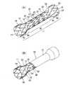
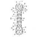
図1及び図2に示すように、この実施形態のステント10は、複数のメッシュ状の開口13が設けられ、軸方向両端部が開口した略円筒状をなしたステント本体11を有している。 As shown in FIGS. 1 and 2, the
このステント本体11は、所定パターンで周方向に延びる線材で構成され、軸方向に沿って所定間隔で配置された複数のストラット部20,22,24と、隣接するストラット部どうしを軸方向に連結する線材で構成される複数の連結部30,32とを有している。 The
この実施形態における各ストラット部20,22,24は、金属線材を、山部や谷部からなる折曲部25を有するように、ジグザグ状に屈曲させて、その周方向両端が連結されて環状に構成されている。ただし、ストラット部は、ジグザグの屈曲パターンに限らず、例えば屈曲部が円弧状をなして波形に延びるパターンであってもよく、枠状のパターンが繋がって周方向に延びるパターンであってもよく、様々なパターンとすることができる。 In each of the
また、図3に示すように、ステント10は、ステント本体11の内面及び/又は外面を覆うように配置されるカバー部材15を有しており、いわゆるカバードステントとなっている。この実施形態におけるカバー部材15は、ステント本体11の内面に配置された内側カバー16と、ステント本体11の外面に配置された外側カバー17とから構成されているが(図3参照)、ステント本体11の内面又は外面の一方のみに被覆させてもよい。 Moreover, as shown in FIG. 3, the
前記ステント本体11について詳述すると、このステント本体11は、小径部40と、該小径部40の軸方向の少なくとも一端側、又は、ステント本体11の軸方向の少なくとも一端側に、小径部40よりも拡径した傾斜部50を介して配置された大径部60とを有している。この実施形態におけるステント本体11は、前記小径部40の軸方向の両端側に、傾斜部50,50を介して大径部60,60がそれぞれ配置された構造をなしている(図2参照)。 The
前記小径部40は、この実施形態の場合、一定外径で所定長さ伸びるストレート形状をなしている。また、この小径部40の軸方向両端部から、斜め外方に向けて次第に拡径するように、傾斜部50,50が延びている。そして、これらの傾斜部50,50の延出方向先端部から、小径部40及び傾斜部50よりも大きな外径の大径部60,60が所定長さで延びている。前記傾斜部50及び前記大径部60によって、いわゆるダンベル形状が構成されている。 In the case of this embodiment, the small-
前記小径部40には、複数のストラット部20,22が軸方向に所定間隔で配置されている。この実施形態の場合、軸方向両端部に配置されたストラット部22は、中間部に配置されたストラット部20よりも折曲部25の数が少なくなっているが(図2参照)、折曲部25の数は同じであってもよい。そして、隣接するストラット部20,20の所定の折曲部25,25どうし、及び、隣接するストラット部20,22の所定の折曲部25,25どうしが、連結部30によって連結されることで、小径部40が構成されている。 In the
一方、各大径部60は、一定の外径で所定長さ伸びるストレート形状をなしている。また、各大径部60には、その最端部(ステント10の軸方向の最端部)に、1つのストラット部24のみが配置されている。そして、この大径部60に配置されたストラット部24の、前記小径部40側を向く折曲部25の全てが、小径部40の軸方向端部に配置されたストラット部22の折曲部25に、傾斜部50に配置された連結部32によって連結されている。 On the other hand, each
また、大径部60に配置されたストラット部24は、小径部40の軸方向端部に配置されたストラット部22の折曲部25に整合する個数で形成されているが、異なる個数で形成されていてもよく、特に限定はされない。 In addition, the
また、図8に示すように、大径部60としては、傾斜部50の延出方向先端部から連続してラッパ状に延びる形状としてもよく、少なくともステントの軸方向最端部に位置するストラット部24を有する構造であればよい。 As shown in FIG. 8, the large-
更に、上記のように、この実施形態における大径部60は、最端部に位置する1つのストラット部24のみで構成されているが、大径部60としては、図10及び図11に示すように、最端部に位置するストラット部24及び該ストラット部24に枠状をなして連結されたストラット部24aのみで構成されていてもよい(これらの実施形態においては後述する)。 Furthermore, as described above, the large-
すなわち、本発明における「大径部」とは、ステントの軸方向の最端部に位置するストラット部、又は、最端部に位置するストラット部と該ストラット部に枠状をなして連結されたストラット部とで構成されているものである。 That is, the “large diameter portion” in the present invention is a strut portion positioned at the endmost portion in the axial direction of the stent, or a strut portion positioned at the endmost portion and connected to the strut portion in a frame shape. It consists of a strut part.
そして、図2に示すように、前記傾斜部50には、小径部40に配置された複数のストラット部20,22の中で、最も傾斜部寄りに位置するストラット部22と、大径部60に配置されたストラット部24の中で、最も傾斜部寄りに位置するストラット部24とを連結する、連結部32のみが存在するように構成されている。すなわち、傾斜部50には、軸方向に向いた折曲部を有するストラット部が存在しない構造となっている。 As shown in FIG. 2, the
また、傾斜部50に配置された連結部32の長さは、前記小径部40に配置されたストラット部20の長さ(折曲部25,25間の長さ)及び連結部30の長さよりも長く、また、前記大径部60に配置されたストラット部24の長さ(折曲部25,25間の長さ)よりも長くなるように形成されている。 Further, the length of the connecting
更に、この実施形態においては、傾斜部50に配置された連結部32は、ステント本体11の軸方向C(図2参照)に対して螺旋形状をなすように延びており、かつ、該連結部32がステント本体11の周方向に複数配置されている。 Furthermore, in this embodiment, the connecting
なお、この実施形態における傾斜部50は、ステント本体11の軸方向Cに対して所定の傾斜角度θで拡径する形状をなしており、連結部32は、小径部40の最も傾斜部寄りに位置するストラット部22の折曲部25から、傾斜部50の傾斜面に沿って、かつ、軸方向Cに対して螺旋をなすように延びて、その延出方向の先端部32aが大径部60に至ると、ステント本体11の軸方向に沿って屈曲して、大径部60に位置するストラット部24の折曲部25に連結されている。 Note that the
また、傾斜部50のステント本体11の軸方向Cに対する傾斜角度(テーパ状の広がり角度)θは、10〜80°であることが好ましく、20〜70°であることがより好ましい。更に、連結部32は、ステント本体11の周方向に対して、2〜18本存在することが好ましく、3〜16本存在することがより好ましい。また、図2に示す傾斜部50の先端部32aを含む軸方向長さLは、3〜80mmであることが好ましく、5〜60mmであることがより好ましい。 The inclination angle (tapered spreading angle) θ of the
更に図13に示すように、ステントを軸方向端部から見たときに、傾斜部50に配置された連結部32の螺旋のねじれ角度Rは、連結部32が、小径部40の最も傾斜部寄りに位置するストラット部22の折曲部25から、大径部60に位置するストラット部24の折曲部25に至る間に、周方向に好ましくは10〜270°、より好ましくは20〜180°回転するように定めるのがよい。 Further, as shown in FIG. 13, when the stent is viewed from the axial end, the helical twist angle R of the connecting
上記のステント本体11の材質は、特に限定されないが、例えば、ステンレス、Ta、Ti、Pt、Au、W等や、Ni−Ti系合金、Co−Cr系合金、Co−Cr−Ni系合金、Cu−Zn−X(X=Al,Fe等)合金、Ni−Ti−X(X=Fe,Cu,V,Co等)合金等の形状記憶合金などが好ましい。 The material of the
また、上記ステント本体11は、メッシュ状に成形された金属筒の、軸方向両端部を拡径させて形成されている。例えば、金属円筒をレーザー加工やエッチング等で加工して、複数のストラット部20,22,24や連結部30,32からなる筒状体を形成し、又は、金属板にレーザー加工等で複数のストラット部20,22,24や連結部30,32を予め形成して、この金属板を屈曲して筒状体に形成する。 The
そして、この筒状体を、例えば、図7に示すような芯材3に被せて、上記筒状体を芯材3の外周形状に適合させる。なお、レーザー加工等からなる上記筒状体の初期内径を、芯材3の小径部4よりも小さく形成することにより、筒状体を芯材3の外周に弾性的に密接させることができる。 And this cylindrical body is covered, for example on the core material 3 as shown in FIG. 7, and the said cylindrical body is adapted to the outer periphery shape of the core material 3. As shown in FIG. In addition, the cylindrical body can be elastically brought into close contact with the outer periphery of the core material 3 by forming the initial inner diameter of the cylindrical body made of laser processing or the like smaller than the small diameter portion 4 of the core material 3.
この状態で、所定の熱処理(例えば、Ni−Ti系合金等の形状記憶合金の場合は形状記憶処理)を施したり、塑性変形させたりすることで、芯材3の外周形状に沿って、小径部40、傾斜部50及び大径部60を形成することができる。なお、ステント本体11の傾斜部50や大径部60は、上記形成方法のみならず、種々の方法により形成することができ、特に限定はされない。 In this state, a predetermined heat treatment (for example, a shape memory alloy in the case of a shape memory alloy such as a Ni—Ti alloy) is subjected to plastic deformation or a small diameter along the outer peripheral shape of the core material 3. The
また、上記ステント本体11は、常時は拡径した状態となる自己拡張型であるが、バルーンカテーテルの外周に装着しておき、ステント内側に配置されたバルーンを膨らませることで、拡径させるバルーン拡径型としてもよい。 The
更に図3に示すように、ステント本体11の大径部60の軸方向一端部には、リング状をなした引き抜き部65が設けられ、これらの引き抜き部65には、ループ状をなした引き抜きワイヤ67が挿通されており、図5及び図6に示すように、この引き抜きワイヤ67を鉗子2等で把持して引っ張ることで、ステント10をカテーテルやシース等の医療用チューブ1に回収できるようになっている。なお、図1(a)及び図2においては、便宜上、引き抜き部65を省略している。 Further, as shown in FIG. 3, one end portion in the axial direction of the
更に上述した、内側カバー16及び外側カバー17からなるカバー部材15は、次のような構造をなしている。すなわち、図3に示すように、内側カバー16は、ステント本体11の内側を被覆すると共に、その厚さ方向途中に至る部分まで埋設し、外側カバー17は、ステント本体11の外側を被覆すると共に、内側カバー16に埋設されていない部分に至るまで埋設しており、両カバー16,17によって、ステント本体11のメッシュ状の開口13が塞がれている。 Further, the
また、内側カバー16及び外側カバー17は、例えば、ポリウレタン、シリコーン、天然ゴム、ナイロンエラストマー、ポリエーテルブロックアミド、ポリエチレン、ポリ塩化ビニル、酢酸ビニルや、更には、ポリテトラフルオロエチレン(PTFE)、パーフルオロアルコキシ樹脂(PFA)、四フッ化エチレン−六フッ化プロピレン共重合体(FEP)、四フッ化エチレン−エチレン共重合体(ETFE)等のフッ素系樹脂、ポリブタジエン等のオレフィン系ゴム、スチレン系エラストマーなどで形成されることが好ましい。 The
なお、図5〜8や、後述する図9〜12においては、便宜上、内側カバー16及び外側カバー17からなるカバー部材15を省略している。 In FIGS. 5 to 8 and FIGS. 9 to 12 to be described later, the
次に、上記構成からなる本発明のステント10の、使用方法の一例について説明する。なお、この使用方法は一例であり、特に限定はされない。 Next, an example of how to use the
図4に示すように、十二指腸7の下部には、乳頭7aが設けられており、この乳頭7aから胆管8や膵管9が分岐して伸びている。また、図示しない肝臓により生成される胆汁は、胆管8内を流動し、乳頭7aを通過して十二指腸7へと供給されるようになっている。ここでは、乳頭7aを通して、胆管8内にステント10を留置する際の手順について説明する。 As shown in FIG. 4, a
なお、本発明のステント10は、胆管8以外にも、膵管9や、十二指腸7、食道、気管、大腸、血管等の管状器官や、体腔、その他の体内組織に留置することもでき、適用箇所は特に限定されない。 In addition to the
まず、ステント10を縮径させて、カテーテルやシース等の医療用チューブ1(図5参照)内に収納する。この状態で周知の方法によって、図示しない内視鏡のルーメンを通じてガイドワイヤを胆管8に挿入した後、同ガイドワイヤを介して医療用チューブ1を挿入していくことで、ステント10を胆管8内に挿入する。そして、医療用チューブ1の先端部が胆管8の所定位置に到達したら、医療用チューブ1を停止する。その後、プッシャ等を介してステント10の移動を規制しつつ、医療用チューブ1を手前に引くことで、医療用チューブ1の先端からステント10を解放させ、ステント10を拡径させることにより、図4に示すように、ステント10の他端側(基端側)を胆管8内に配置すると共に、ステント10の一端側(先端側)を乳頭7aからやや突き出るように配置して、ステント10を留置する。 First, the diameter of the
このとき、このステント10においては、傾斜部50を介して大径部60を設けたので、胆管8等の体内組織の所定位置にステント10を留置したときに、大径部60が体内組織の内壁に密接することとなり、体内組織に対するアンカリング効果を高めることができ、ステント10の位置ずれを抑制することができる(図4参照)。 At this time, since the
一方、ステント10の内腔が閉塞したり、不要となったり、或いは、交換したりしたい場合に、ステント10を体内から回収する必要が生じることがある。 On the other hand, when the lumen of the
この場合には、例えば、内視鏡等を通じて医療用チューブ1を、ステント10の一端近傍まで挿入配置し、その状態で、図5に示すように、ステント本体11の引き抜きワイヤ67を鉗子2で把持して、ステント10を操作者の手元側に向けて引っ張ったり、或いは、図示しないループ状のスネアを、ステント一端側に引っ掛けて、スネアを介してステントを引っ張る。すると、ステント一端側の大径部60が縮径して医療用チューブ1内に引き込まれると共に、ステント10の小径部40が医療用チューブ内に収容され、更に、医療用チューブ1の先端開口に、ステント他端側の傾斜部50が押圧されて縮径し、該傾斜部50を介して、ステント他端側の大径部60が縮径しつつ、医療用チューブ1内に収容されていく(図5参照)。 In this case, for example, the
このとき、このステント10においては、胆管8内で最もアンカリング効果を発揮するステント本体11の傾斜部50に、連結部32のみが存在するように構成されていて、引き抜き方向に向く遊離した角部、例えば、ジグザグパターンからなるストラット部の山状の折曲部25が存在しないので、上記のように、傾斜部50を介して大径部60を縮径させるときに、傾斜部50が縮径しやすく、ストラット部の角部が胆管8等の内壁に引っ掛かったり、医療用チューブ1の先端開口に引っ掛かることが抑制され、ステント10を医療用チューブ1内にスムーズに引き込んで体内から抜き出すことができる(図6参照)。 At this time, in this
また、体内組織の所定位置にステント10を留置するときに、ステント10の位置を修正する際にも、その作業を行いやすい。すなわち、ステント留置時には、医療用チューブ1の先端部からステント10を徐々に開放して、その位置を確認しつつ留置していくが、位置ずれしている場合は、上述の、ステント10を体内から回収する作業と同様に、ステント一端側を引っ張って医療用チューブ1内に引き戻す。この際に、最もアンカリング効果を発揮するステント本体11の傾斜部50に連結部32のみが存在するので、ステント引っ張り時に、傾斜部50が縮径しやすく、傾斜部50が医療用チューブ1の先端開口に引っ掛かることが抑制され、医療用チューブ1内にステント10をスムーズに引き込むことができる(図6参照)。 Further, when the
更にこの実施形態においては、図2に示すように、ステント本体11の傾斜部50に配置された連結部32は、ステント本体11の軸方向Cに対して螺旋形状をなすように延びているので、体内組織の所定位置にステント10を留置する際において、ストラット部の存在しない傾斜部50においても、充分な拡張力が得られるようにすることができる。 Furthermore, in this embodiment, as shown in FIG. 2, the connecting
図9には、本発明に係るステントの第2実施形態が示されている。なお、前記実施形態と実質的に同一部分には同符号を付してその説明を省略する。 FIG. 9 shows a second embodiment of the stent according to the present invention. Note that substantially the same parts as those of the above-described embodiment are denoted by the same reference numerals, and description thereof is omitted.
この実施形態のステント10Aは、傾斜部50の拡径形状が、前記実施形態と異なっている。 In the
すなわち、図9に示すように、この実施形態における傾斜部50は、ステント本体11の軸方向Cに対して所定の傾斜角度θ1で途中まで広がり、その後にステント本体11の軸方向Cに対して、前記傾斜角度θ2よりも小さい傾斜角度θ2で広がる形状、すなわち途中でテーパの角度が変わる形状をなしている。 That is, as shown in FIG. 9, the
そして、連結部34は、傾斜角度θ1で広がるテーパ面に沿って延びる第1線状部35と、傾斜角度θ2で広がるテーパ面に沿って延びる第2線状部36とで構成されている。このため、第1線状部35と第2線状部36との間に傾斜角の変わる緩やかな角部が形成され、その部分において、体内組織の内壁に対する傾斜部50のアンカリング効果を高めることができる。 And the
なお、第1線状部35が配置された傾斜部50の、ステント本体11の軸方向Cに対する傾斜角度θ1は、10〜80°であることが好ましく、20〜70°であることがより好ましい。また、第2線状部36が配置された傾斜部50の、ステント本体11の軸方向Cに対する傾斜角度θ2は、25〜65°であることが好ましく、30〜60°であることがより好ましい。 In addition, inclination | tilt angle (theta) 1 with respect to the axial direction C of the stent
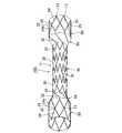
図10には、本発明に係るステントの第3実施形態が示されている。なお、前記実施形態と実質的に同一部分には同符号を付してその説明を省略する。 FIG. 10 shows a third embodiment of the stent according to the present invention. Note that substantially the same parts as those of the above-described embodiment are denoted by the same reference numerals, and description thereof is omitted.
この実施形態のステント10Bは、大径部60の構造が前記実施形態と異なっている。 In the
すなわち、図10に示すように、この実施形態における大径部60は、ステント10Bの軸方向の最端部に位置するストラット部24及び該ストラット部24に枠状をなして連結されたストラット部24aのみで構成されている。また、大径部60の、最端部に配置されたストラット部24の小径部40側を向く折曲部25の全てが、該ストラット部24に隣接して対向配置されたストラット部24aの折曲部25の全てに、直接的に互いに連結されていて、菱形の開口13を有する枠状パターンが周方向に配列されている。 That is, as shown in FIG. 10, the large-
そして、この実施形態によれば、大径部60は、その最端部に位置するストラット部24と、該ストラット部24に、枠状をなして連結されたストラット部24aとからなり、枠状をなすパターンが周方向に配列された形状をなすので、体内へのステント留置時に、大径部60における拡張力を高めることができる。 And according to this embodiment, the
図11には、本発明に係るステントの第4実施形態が示されている。なお、前記実施形態と実質的に同一部分には同符号を付してその説明を省略する。 FIG. 11 shows a fourth embodiment of the stent according to the present invention. Note that substantially the same parts as those of the above-described embodiment are denoted by the same reference numerals, and description thereof is omitted.
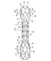
この実施形態のステント10Cは、大径部60の構造が前記実施形態と異なっている。 In the stent 10C of this embodiment, the structure of the
すなわち、この実施形態における大径部60は、ステント10Cの軸方向の最端部に位置するストラット部24及び該ストラット部24に枠状をなして連結されたストラット部24aのみで構成されている。また、大径部60の、最端部に配置されたストラット部24の小径部40側を向く折曲部25の全てが、該ストラット部24に隣接して対向配置されたストラット部24aの折曲部25の全てに、ストラット部24の折曲部25から延出した線状部24bを介して連結されて、略菱形の開口13を有する枠状パターンが周方向に配列されている。 That is, the large-
この第4実施形態においても、前記第3実施形態と同様に、大径部60は、その最端部に位置するストラット部24と、該ストラット部24に、枠状をなして連結されたストラット部24aとからなり、枠状をなすパターンが周方向に配列された形状をなすので、体内へのステント留置時に、大径部60における拡張力を高めることができる。 Also in the fourth embodiment, as in the third embodiment, the large-
図12には、本発明に係るステントの第5実施形態が示されている。なお、前記実施形態と実質的に同一部分には同符号を付してその説明を省略する。 FIG. 12 shows a fifth embodiment of the stent according to the present invention. Note that substantially the same parts as those of the above-described embodiment are denoted by the same reference numerals, and description thereof is omitted.
この実施形態のステント10Dは、傾斜部50に配置された連結部の構造が、前記実施形態と異なっている。 In the
すなわち、図12に示すように、この実施形態における連結部37は、ステント本体11をその周面に対して垂直方向から見たときに、周方向に折曲した部分37aを有している。そして、この周方向に折曲した部分37aの端部に、ストラット部24の折曲部25(谷部)が連結されており、このストラット部24が大径部60を構成している(連結部37の周方向に折曲した部分37aは含まない)。なお、この実施形態では、連結部37の螺旋方向に対して、連結部37aは、周方向に逆向きに延びるように折曲され、その折曲角度が比較的大きくされているが、上記折曲角度は特に限定されない。 That is, as shown in FIG. 12, the connecting
そして、この実施形態によれば、傾斜部50に配置された連結部37は、ステント本体11をその周面に対して垂直方向から見たときに、周方向に折曲した部分37aを有しているので、体内の所定位置にステント10Dを留置したときの、体内組織の内壁に対する傾斜部50のアンカリング効果を高めることができる。 And according to this embodiment, the
なお、本発明は、上述した実施形態に限定されるものではなく、本発明の要旨の範囲内で、各種の変形実施形態が可能であり、そのような実施形態も本発明の範囲に含まれる。 It should be noted that the present invention is not limited to the above-described embodiment, and various modified embodiments are possible within the scope of the present invention, and such an embodiment is also included in the scope of the present invention. .
10,10A,10B,10C,10D ステント
11 ステント本体
15 カバー部材
20,22,24,24a ストラット部
25 折曲部
30,32,34,37 連結部
35 第1線状部
36第2線状部
37a 周方向に折曲した部分
40 小径部
50 傾斜部
60 大径部10, 10A, 10B, 10C,
Claims (4)
Translated fromJapanese該ステント本体の内面及び/又は外面を覆うように配置されるカバー部材とを備え、
前記ステント本体は、小径部と、該小径部の軸方向の少なくとも一端側に、傾斜部を介して配置された大径部とを有しており、
前記大径部は、最端部に位置するストラット部、又は、最端部に位置するストラット部と該ストラット部に枠状をなして連結されたストラット部とで構成され、
前記傾斜部には、前記小径部に配置された前記ストラット部の中で、最も前記傾斜部寄りに位置する前記ストラット部と、前記大径部に配置された前記ストラット部の中で、最も前記傾斜部寄りに位置する前記ストラット部とを連結する、前記連結部のみが存在するように構成されており、
前記大径部に配置された前記ストラット部の中で、最も前記傾斜部寄りに位置する前記ストラット部の、前記小径部側を向く折曲部の全てが、前記連結部によって、前記小径部に配置された前記ストラット部の中で、最も前記傾斜部寄りに位置する前記ストラット部に連結されていることを特徴とするステント。A plurality of strut portions made of wire rods extending in the circumferential direction in a predetermined pattern and arranged at predetermined intervals along the axial direction, and a plurality of connection portions made of wire rods connecting adjacent strut portions in the axial direction. A stent body having:
A cover member arranged to cover the inner surface and / or outer surface of the stent body,
The stent main body has a small diameter portion and a large diameter portion disposed via an inclined portion on at least one end side in the axial direction of the small diameter portion,
The large diameter portion is composed of a strut portion located at the endmost portion, or a strut portion located at the endmost portion and a strut portion connected in a frame shape to the strut portion,
In the inclined portion, the strut portion located closest to the inclined portion among the strut portions arranged in the small diameter portion, and the strut portion arranged in the large diameter portion, the most connecting said strut portion located on the inclined portion closer,Made up such that only the connecting portion is present,
Of the strut portions arranged in the large diameter portion, all of the bent portions facing the small diameter portion side of the strut portion located closest to the inclined portion are connected to the small diameter portion by the connecting portion. The stent is connected to the strut portion positioned closest to the inclined portion among the arranged strut portions.
Applications Claiming Priority (3)
| Application Number | Priority Date | Filing Date | Title |
|---|---|---|---|
| JP2015225897 | 2015-11-18 | ||
| JP2015225897 | 2015-11-18 | ||
| PCT/JP2016/083456WO2017086239A1 (en) | 2015-11-18 | 2016-11-11 | Stent |
Publications (2)
| Publication Number | Publication Date |
|---|---|
| JPWO2017086239A1 JPWO2017086239A1 (en) | 2018-08-09 |
| JP6458165B2true JP6458165B2 (en) | 2019-01-23 |
Family
ID=58718866
Family Applications (1)
| Application Number | Title | Priority Date | Filing Date |
|---|---|---|---|
| JP2017551848AActiveJP6458165B2 (en) | 2015-11-18 | 2016-11-11 | Stent |
Country Status (3)
| Country | Link |
|---|---|
| JP (1) | JP6458165B2 (en) |
| CN (1) | CN108289748B (en) |
| WO (1) | WO2017086239A1 (en) |
Families Citing this family (5)
| Publication number | Priority date | Publication date | Assignee | Title |
|---|---|---|---|---|
| GB201718299D0 (en) | 2017-11-03 | 2017-12-20 | Ab Wasstand Dev | Stents |
| WO2021182319A1 (en)* | 2020-03-09 | 2021-09-16 | 川澄化学工業株式会社 | Stent graft and stent graft skeleton |
| CN114617684B (en)* | 2022-03-14 | 2025-02-18 | 江苏博朗森思医疗器械有限公司 | Bracket system |
| CN116271501B (en)* | 2023-04-26 | 2024-06-11 | 心擎医疗(苏州)股份有限公司 | Catheter pump |
| JP7711133B2 (en)* | 2023-08-25 | 2025-07-22 | 日本ライフライン株式会社 | Stent and method for manufacturing stent |
Family Cites Families (12)
| Publication number | Priority date | Publication date | Assignee | Title |
|---|---|---|---|---|
| US6129755A (en)* | 1998-01-09 | 2000-10-10 | Nitinol Development Corporation | Intravascular stent having an improved strut configuration |
| CN1158053C (en)* | 2000-12-15 | 2004-07-21 | 李艳芳 | Artificial blood vessel and anastomat |
| EP1621158A1 (en)* | 2004-07-28 | 2006-02-01 | Cordis Corporation | Reduced profile abdominal aortic aneurysm device |
| US8262720B2 (en)* | 2004-12-02 | 2012-09-11 | Nitinol Development Corporation | Prosthesis comprising dual tapered stent |
| WO2008096512A1 (en)* | 2007-02-09 | 2008-08-14 | Piolax Medical Devices, Inc. | Stent |
| US8066757B2 (en)* | 2007-10-17 | 2011-11-29 | Mindframe, Inc. | Blood flow restoration and thrombus management methods |
| CN201135516Y (en)* | 2007-12-13 | 2008-10-22 | 乐普(北京)医疗器械股份有限公司 | variable diameter stent |
| WO2011004374A1 (en)* | 2009-07-09 | 2011-01-13 | Endospan Ltd. | Apparatus for closure of a lumen and methods of using the same |
| JP5691184B2 (en)* | 2010-01-29 | 2015-04-01 | 日本ゼオン株式会社 | Covered stent |
| US20130033861A1 (en)* | 2011-08-01 | 2013-02-07 | Kevin Orton | Retrofit LED light Panel |
| PL222299B1 (en)* | 2012-06-19 | 2016-07-29 | Balton Spółka Z Ograniczoną Odpowiedzialnością | Bifurcation stent system for endovascular stent implantation and a method for stent implantation for bifurcation |
| CN103462728B (en)* | 2013-09-13 | 2018-07-31 | 徐州亚太科技有限公司 | A kind of aortic valve prosthesis's holder and its transport system through conduit implantation |
- 2016
- 2016-11-11JPJP2017551848Apatent/JP6458165B2/enactiveActive
- 2016-11-11CNCN201680067626.1Apatent/CN108289748B/ennot_activeExpired - Fee Related
- 2016-11-11WOPCT/JP2016/083456patent/WO2017086239A1/ennot_activeCeased
Also Published As
| Publication number | Publication date |
|---|---|
| WO2017086239A1 (en) | 2017-05-26 |
| CN108289748B (en) | 2020-08-11 |
| CN108289748A (en) | 2018-07-17 |
| JPWO2017086239A1 (en) | 2018-08-09 |
Similar Documents
| Publication | Publication Date | Title |
|---|---|---|
| JP5795364B2 (en) | Stent | |
| JP6458165B2 (en) | Stent | |
| JP6353933B2 (en) | Stent | |
| JP5921682B2 (en) | Stent | |
| JP5575327B2 (en) | Stent | |
| JP5813230B2 (en) | Stent | |
| KR20190064595A (en) | Flexible stent | |
| JP7267245B2 (en) | stent | |
| JP4422578B2 (en) | Stent and stent graft | |
| JP5717592B2 (en) | Tubular organ treatment device | |
| CN111356420B (en) | Non-invasive spacer bracket | |
| JP6705025B2 (en) | Stent | |
| CN110251285B (en) | Tapered Vascular Stent | |
| JP6925869B2 (en) | Stent | |
| JP6605907B2 (en) | Stent | |
| JP2017070406A (en) | Stent | |
| JP6199181B2 (en) | Stent | |
| JP4835113B2 (en) | Stent | |
| JPWO2020013209A1 (en) | Stent | |
| JP2017164304A (en) | Treatment device | |
| JP6912944B2 (en) | Foreign body discharge device for tubular organs | |
| JP2014018574A (en) | Guide wire | |
| JPWO2020065743A1 (en) | Stents and stent grafts |
Legal Events
| Date | Code | Title | Description |
|---|---|---|---|
| A529 | Written submission of copy of amendment under article 34 pct | Free format text:JAPANESE INTERMEDIATE CODE: A5211 Effective date:20180418 | |
| A621 | Written request for application examination | Free format text:JAPANESE INTERMEDIATE CODE: A621 Effective date:20180418 | |
| TRDD | Decision of grant or rejection written | ||
| A01 | Written decision to grant a patent or to grant a registration (utility model) | Free format text:JAPANESE INTERMEDIATE CODE: A01 Effective date:20181218 | |
| A61 | First payment of annual fees (during grant procedure) | Free format text:JAPANESE INTERMEDIATE CODE: A61 Effective date:20181221 | |
| R150 | Certificate of patent or registration of utility model | Ref document number:6458165 Country of ref document:JP Free format text:JAPANESE INTERMEDIATE CODE: R150 |