JP6456908B2 - Automatic three-way diverter valve - Google Patents
Automatic three-way diverter valveDownload PDFInfo
- Publication number
- JP6456908B2 JP6456908B2JP2016500569AJP2016500569AJP6456908B2JP 6456908 B2JP6456908 B2JP 6456908B2JP 2016500569 AJP2016500569 AJP 2016500569AJP 2016500569 AJP2016500569 AJP 2016500569AJP 6456908 B2JP6456908 B2JP 6456908B2
- Authority
- JP
- Japan
- Prior art keywords
- fluid
- valve
- delivery device
- component
- loading
- Prior art date
- Legal status (The legal status is an assumption and is not a legal conclusion. Google has not performed a legal analysis and makes no representation as to the accuracy of the status listed.)
- Expired - Fee Related
Links
- 239000012530fluidSubstances0.000claimsdescription295
- 238000012384transportation and deliveryMethods0.000claimsdescription125
- 239000000463materialSubstances0.000claimsdescription61
- 238000000034methodMethods0.000claimsdescription31
- 238000004891communicationMethods0.000claimsdescription30
- 239000013536elastomeric materialSubstances0.000claimsdescription3
- 239000007788liquidSubstances0.000claimsdescription2
- 230000004044responseEffects0.000claimsdescription2
- 238000009826distributionMethods0.000description25
- 239000000203mixtureSubstances0.000description17
- 239000012620biological materialSubstances0.000description7
- 102000009123FibrinHuman genes0.000description6
- 108010073385FibrinProteins0.000description6
- BWGVNKXGVNDBDI-UHFFFAOYSA-NFibrin monomerChemical compoundCNC(=O)CNC(=O)CNBWGVNKXGVNDBDI-UHFFFAOYSA-N0.000description6
- 108010049003FibrinogenProteins0.000description6
- 102000008946FibrinogenHuman genes0.000description6
- 108090000190ThrombinProteins0.000description6
- 229950003499fibrinDrugs0.000description6
- 229940012952fibrinogenDrugs0.000description6
- 238000002156mixingMethods0.000description6
- 229960004072thrombinDrugs0.000description6
- 239000004033plasticSubstances0.000description5
- 239000011521glassSubstances0.000description4
- 239000005060rubberSubstances0.000description4
- 239000000853adhesiveSubstances0.000description3
- 230000001070adhesive effectEffects0.000description3
- 230000006835compressionEffects0.000description3
- 238000007906compressionMethods0.000description3
- 230000036512infertilityEffects0.000description3
- 239000002184metalSubstances0.000description3
- 239000012812sealant materialSubstances0.000description3
- 238000007789sealingMethods0.000description3
- NIXOWILDQLNWCW-UHFFFAOYSA-MAcrylateChemical compound[O-]C(=O)C=CNIXOWILDQLNWCW-UHFFFAOYSA-M0.000description2
- 230000000712assemblyEffects0.000description2
- 238000000429assemblyMethods0.000description2
- 238000004140cleaningMethods0.000description2
- 239000011248coating agentSubstances0.000description2
- 238000000576coating methodMethods0.000description2
- 239000003814drugSubstances0.000description2
- 230000007246mechanismEffects0.000description2
- 238000003825pressingMethods0.000description2
- 238000003860storageMethods0.000description2
- 229920000742CottonPolymers0.000description1
- 229920001651CyanoacrylatePolymers0.000description1
- MWCLLHOVUTZFKS-UHFFFAOYSA-NMethyl cyanoacrylateChemical compoundCOC(=O)C(=C)C#NMWCLLHOVUTZFKS-UHFFFAOYSA-N0.000description1
- 150000001252acrylic acid derivativesChemical class0.000description1
- 230000004075alterationEffects0.000description1
- 230000004323axial lengthEffects0.000description1
- 230000000903blocking effectEffects0.000description1
- 239000007795chemical reaction productSubstances0.000description1
- 238000011109contaminationMethods0.000description1
- 238000002716delivery methodMethods0.000description1
- -1for exampleSubstances0.000description1
- 239000007789gasSubstances0.000description1
- 238000005304joiningMethods0.000description1
- 238000012423maintenanceMethods0.000description1
- 238000004519manufacturing processMethods0.000description1
- 230000013011matingEffects0.000description1
- 238000005259measurementMethods0.000description1
- 238000004806packaging method and processMethods0.000description1
- 210000002381plasmaAnatomy0.000description1
- 229920001296polysiloxanePolymers0.000description1
- 239000002243precursorSubstances0.000description1
- 230000008569processEffects0.000description1
- 230000002787reinforcementEffects0.000description1
- 239000000565sealantSubstances0.000description1
- 239000007787solidSubstances0.000description1
- 230000001954sterilising effectEffects0.000description1
- 238000004659sterilization and disinfectionMethods0.000description1
- 239000000126substanceSubstances0.000description1
- 210000001519tissueAnatomy0.000description1
Images


Classifications
- B—PERFORMING OPERATIONS; TRANSPORTING
- B65—CONVEYING; PACKING; STORING; HANDLING THIN OR FILAMENTARY MATERIAL
- B65B—MACHINES, APPARATUS OR DEVICES FOR, OR METHODS OF, PACKAGING ARTICLES OR MATERIALS; UNPACKING
- B65B3/00—Packaging plastic material, semiliquids, liquids or mixed solids and liquids, in individual containers or receptacles, e.g. bags, sacks, boxes, cartons, cans, or jars
- B65B3/04—Methods of, or means for, filling the material into the containers or receptacles
- B65B3/10—Methods of, or means for, filling the material into the containers or receptacles by application of pressure to material
- B65B3/12—Methods of, or means for, filling the material into the containers or receptacles by application of pressure to material mechanically, e.g. by pistons or pumps
- A—HUMAN NECESSITIES
- A61—MEDICAL OR VETERINARY SCIENCE; HYGIENE
- A61B—DIAGNOSIS; SURGERY; IDENTIFICATION
- A61B17/00—Surgical instruments, devices or methods
- A61B17/00491—Surgical glue applicators
- A—HUMAN NECESSITIES
- A61—MEDICAL OR VETERINARY SCIENCE; HYGIENE
- A61M—DEVICES FOR INTRODUCING MEDIA INTO, OR ONTO, THE BODY; DEVICES FOR TRANSDUCING BODY MEDIA OR FOR TAKING MEDIA FROM THE BODY; DEVICES FOR PRODUCING OR ENDING SLEEP OR STUPOR
- A61M39/00—Tubes, tube connectors, tube couplings, valves, access sites or the like, specially adapted for medical use
- A61M39/22—Valves or arrangement of valves
- A61M39/223—Multiway valves
- A—HUMAN NECESSITIES
- A61—MEDICAL OR VETERINARY SCIENCE; HYGIENE
- A61M—DEVICES FOR INTRODUCING MEDIA INTO, OR ONTO, THE BODY; DEVICES FOR TRANSDUCING BODY MEDIA OR FOR TAKING MEDIA FROM THE BODY; DEVICES FOR PRODUCING OR ENDING SLEEP OR STUPOR
- A61M39/00—Tubes, tube connectors, tube couplings, valves, access sites or the like, specially adapted for medical use
- A61M39/22—Valves or arrangement of valves
- A61M39/26—Valves closing automatically on disconnecting the line and opening on reconnection thereof
- B—PERFORMING OPERATIONS; TRANSPORTING
- B65—CONVEYING; PACKING; STORING; HANDLING THIN OR FILAMENTARY MATERIAL
- B65B—MACHINES, APPARATUS OR DEVICES FOR, OR METHODS OF, PACKAGING ARTICLES OR MATERIALS; UNPACKING
- B65B3/00—Packaging plastic material, semiliquids, liquids or mixed solids and liquids, in individual containers or receptacles, e.g. bags, sacks, boxes, cartons, cans, or jars
- B65B3/003—Filling medical containers such as ampoules, vials, syringes or the like
- F—MECHANICAL ENGINEERING; LIGHTING; HEATING; WEAPONS; BLASTING
- F16—ENGINEERING ELEMENTS AND UNITS; GENERAL MEASURES FOR PRODUCING AND MAINTAINING EFFECTIVE FUNCTIONING OF MACHINES OR INSTALLATIONS; THERMAL INSULATION IN GENERAL
- F16K—VALVES; TAPS; COCKS; ACTUATING-FLOATS; DEVICES FOR VENTING OR AERATING
- F16K11/00—Multiple-way valves, e.g. mixing valves; Pipe fittings incorporating such valves
- F16K11/02—Multiple-way valves, e.g. mixing valves; Pipe fittings incorporating such valves with all movable sealing faces moving as one unit
- A—HUMAN NECESSITIES
- A61—MEDICAL OR VETERINARY SCIENCE; HYGIENE
- A61B—DIAGNOSIS; SURGERY; IDENTIFICATION
- A61B17/00—Surgical instruments, devices or methods
- A61B17/00491—Surgical glue applicators
- A61B2017/00495—Surgical glue applicators for two-component glue
- A—HUMAN NECESSITIES
- A61—MEDICAL OR VETERINARY SCIENCE; HYGIENE
- A61M—DEVICES FOR INTRODUCING MEDIA INTO, OR ONTO, THE BODY; DEVICES FOR TRANSDUCING BODY MEDIA OR FOR TAKING MEDIA FROM THE BODY; DEVICES FOR PRODUCING OR ENDING SLEEP OR STUPOR
- A61M39/00—Tubes, tube connectors, tube couplings, valves, access sites or the like, specially adapted for medical use
- A61M39/22—Valves or arrangement of valves
- A61M39/24—Check- or non-return valves
- A61M2039/2433—Valve comprising a resilient or deformable element, e.g. flap valve, deformable disc
- Y—GENERAL TAGGING OF NEW TECHNOLOGICAL DEVELOPMENTS; GENERAL TAGGING OF CROSS-SECTIONAL TECHNOLOGIES SPANNING OVER SEVERAL SECTIONS OF THE IPC; TECHNICAL SUBJECTS COVERED BY FORMER USPC CROSS-REFERENCE ART COLLECTIONS [XRACs] AND DIGESTS
- Y10—TECHNICAL SUBJECTS COVERED BY FORMER USPC
- Y10T—TECHNICAL SUBJECTS COVERED BY FORMER US CLASSIFICATION
- Y10T137/00—Fluid handling
- Y10T137/8593—Systems
- Y10T137/86493—Multi-way valve unit
Landscapes
- Health & Medical Sciences (AREA)
- Engineering & Computer Science (AREA)
- Heart & Thoracic Surgery (AREA)
- Life Sciences & Earth Sciences (AREA)
- Public Health (AREA)
- Animal Behavior & Ethology (AREA)
- General Health & Medical Sciences (AREA)
- Veterinary Medicine (AREA)
- Biomedical Technology (AREA)
- Mechanical Engineering (AREA)
- Surgery (AREA)
- Hematology (AREA)
- Anesthesiology (AREA)
- Pulmonology (AREA)
- General Engineering & Computer Science (AREA)
- Medical Informatics (AREA)
- Molecular Biology (AREA)
- Nuclear Medicine, Radiotherapy & Molecular Imaging (AREA)
- Infusion, Injection, And Reservoir Apparatuses (AREA)
- Coating Apparatus (AREA)
- Multiple-Way Valves (AREA)
Description
Translated fromJapanese本発明は、生体材料などの材料の、送達装置への装填と分配のための三方ダイバータ弁組立体に関する。ダイバータ弁組立体は、リザーバから出口ポートへの分配のための第1の位置から、装填ポートからリザーバ内への装填のための第2の位置へ自動的に切り替わる弾性体を含む。 The present invention relates to a three-way diverter valve assembly for loading and dispensing materials, such as biomaterials, into a delivery device. The diverter valve assembly includes an elastic body that automatically switches from a first position for dispensing from the reservoir to the outlet port to a second position for loading from the loading port into the reservoir.
シリンジなどの流体材料送達のための装置は、典型的には、分配端又は分配先端と、送達前に流体材料を収容するサイズと形状の流体収容胴部又はリザーバと、を含む。ある材料向けの、具体的には生体材料向けの送達組立体は、典型的には装置に装填済の生体流体含まない。したがって、装置は、送達されるべき生体材料又は複数の生体材料で、その使用の前に装填されなければならない。このような材料の装填と分配ができれば、装置は毎回再装填されて多数回の送達のための再利用が可能となる。更に、装置に装填できることで、材料は装填の前までシールされた容器内に留まることができるので、送達されるべき材料の汚染又は変質の危険が低下する。 An apparatus for fluid material delivery, such as a syringe, typically includes a dispensing end or dispensing tip and a fluid containing body or reservoir sized and shaped to contain the fluid material prior to delivery. Delivery assemblies for certain materials, and in particular for biomaterials, typically do not contain biofluid preloaded in the device. Thus, the device must be loaded with the biomaterial or biomaterials to be delivered prior to its use. If such materials can be loaded and dispensed, the device can be reloaded each time and reused for multiple deliveries. Furthermore, the ability to load the device reduces the risk of contamination or alteration of the material to be delivered, since the material can remain in the sealed container prior to loading.
2つ以上の成分の混合によって形成されるマルチパート組成物では、それぞれの異なる成分の装置への装填がより困難である。これらの成分は、送達されるべき最終組成物の混合及び形成が早すぎないように、送達組立体に装填されるとき別々のままであることが必要である。このようなマルチパート組成物の1つがフィブリンであり、それはトロンビンとフィブリノーゲンの組合せによって形成される。これら2種の前駆成分が一緒に混合され、次いでその結果のフィブリン組成物が混合のすぐあとに送達される。その他のマルチパート組成物として、アクリレートなどの種々の接着剤がある。 In a multi-part composition formed by mixing two or more components, it is more difficult to load each different component into the device. These components need to remain separate when loaded into the delivery assembly so that the final composition to be delivered is not prematurely mixed and formed. One such multipart composition is fibrin, which is formed by a combination of thrombin and fibrinogen. These two precursor components are mixed together and then the resulting fibrin composition is delivered immediately after mixing. Other multipart compositions include various adhesives such as acrylates.
シリンジなどの送達組立体内に、マルチパート成分を装填するための様々な試みがなされてきた。典型的な先行技術の方法では、1つの分配先端(又は複数の先端)を、少なくとも1つの流体を収容したビン内に配置することと、プランジャを引くことと、したがって、流体を胴部又はリザーバ内に引き込むこととに依存している。もう1つの先行技術では、装置の送達端と装置のリザーバとの間の位置で、装置を装填構成要素に連結することによって、成分が装填される。装填構成要素がリザーバと流体連通になっているので、流体がリザーバに入ることが可能となる。しかしながら、このようなタイプの組立体は、装填ポートでのダイバータ弁の機能を必要とすることが多い。ダイバータ弁は、所望の位置への流れを制限するように、装填構成から分配構成へ切り替わる。装填構成では、弁は、装置の装填ポートとリザーバとの間の連通のみを可能とするように位置決めされ、したがって装填ポートと分配端の流体連通は遮断される。装填後は、弁は取り除かれてもよく、又は分配構成に切換えられてもよく、これによって、装填ポートと分配端との流体連通が遮断される一方、分配端とリザーバとの流体連通が可能となる。 Various attempts have been made to load multipart components into a delivery assembly such as a syringe. In a typical prior art method, a dispensing tip (or tips) is placed in a bin containing at least one fluid, a plunger is pulled, and thus the fluid is transferred to a barrel or reservoir. Depends on drawing in. In another prior art, components are loaded by connecting the device to a loading component at a location between the delivery end of the device and the reservoir of the device. Since the loading component is in fluid communication with the reservoir, fluid can enter the reservoir. However, this type of assembly often requires the function of a diverter valve at the loading port. The diverter valve switches from the loading configuration to the dispensing configuration to limit flow to the desired position. In the loading configuration, the valve is positioned to allow only communication between the loading port of the device and the reservoir, and thus fluid communication between the loading port and the dispensing end is blocked. After loading, the valve may be removed or switched to a dispensing configuration, which shuts off fluid communication between the loading port and the dispensing end while allowing fluid communication between the dispensing end and the reservoir. It becomes.
しかしながらこのような装置では、弁組立体の、ある構成から別の構成への切換えが、スイッチや回動可能な要素などによる手動で行われ、したがって、弁を適切に回転させないなどの人的エラーによっていくらかの高価な材料が失われることがある。構成の適切な切換えの失敗はまた、無菌状態の喪失、具体的には生体成分での無菌状態喪失を引き起こすことがある。更に、従来の弁は極めて脆弱であり、過剰な力で間違った方向に回されると破損することがある。そのうえ、使用者が弁の配向を適切な構成に切換える工程を単に忘れることもあり得る。弁の配向が分配方向に切換えられていなければ、生体材料は適切に分配されないことになる。加えて、複数成分材料用の複数のポートを含み得る装置のそれぞれの装填ポートに対して、正確な構成が管理されなければならない。そのうえ、組立体のそれぞれの弁を回さなければならず、これはより多くの人的エラーを起こしやすい。最後に、貯蔵容器と装置との間の液密な流体接続、貯蔵容器とダイバータ弁要素との機械的係合、及びダイバータ弁の正確な位置決め、の調整を同時に可能とすることの必要性によって、製作許容誤差が複雑になり、機能に満足できないことになり得る。 However, in such devices, the switching of the valve assembly from one configuration to another is done manually, such as with a switch or pivotable element, and thus human errors such as not properly rotating the valve. Can cause some expensive material to be lost. Failure to properly switch configurations can also lead to loss of sterility, particularly loss of sterility with biological components. Furthermore, conventional valves are extremely fragile and can break if turned in the wrong direction with excessive force. Moreover, the user may simply forget the process of switching the valve orientation to the proper configuration. If the valve orientation is not switched in the dispensing direction, the biomaterial will not be dispensed properly. In addition, the exact configuration must be managed for each loading port of the device that can include multiple ports for multiple component materials. In addition, each valve of the assembly must be turned, which is more prone to human error. Finally, by the need to be able to simultaneously adjust the fluid-tight fluid connection between the storage container and the device, the mechanical engagement between the storage container and the diverter valve element, and the precise positioning of the diverter valve. , Manufacturing tolerances can be complicated and not satisfactory in function.
したがって、先行技術の問題を避けて、材料が送達組立体に装填され、またそこからの分配を可能とする改善された方法の必要性が存在する。本発明の装置は、自動弁組立体を提供する。 Thus, there is a need for an improved method that avoids the problems of the prior art and allows materials to be loaded into and delivered from the delivery assembly. The apparatus of the present invention provides an automatic valve assembly.
第1の実施形態では、流体送達装置が三方ダイバータ弁組立体を含み、三方ダイバータ弁組立体が、弁本体と弁キャップとを有し、それぞれアクセス開口を有する第1の流体通路と、第2の流体通路と、第3の流体通路と、を提供する、弁ハウジングと、弁ハウジング内の弾性弁構成要素と、を含み、弾性弁構成要素が、第1の位置から第2の位置へ移動可能であり、第1の位置が第2の流体通路と第3の流体通路との間に流体経路を提供し、第2の位置が第1の流体通路と第2の流体通路との間に流体経路を提供する。In a first embodiment, a fluid delivery device includes a three-way diverter valve assembly, the three-way diverter valve assembly having a valve body and a valve cap, each having an access opening, and a second A valve housing and a resilient valve component in the valve housing, wherein the resilient valve component moves from the first position to the second position. A first position provides a fluid path between thesecond fluid path and thethird fluid path, and a second position is between thefirst fluid path and thesecond fluid path. Provide a fluid path.
別の実施形態では、流体送達装置を装填する方法であって、流体送達装置を使用することであって、流体送達装置が、少なくとも1つのチューブ状胴部を含むヘッドピースであって、チューブ状胴部が、チューブ状胴部の内部に設置されたプランジャを含む、ヘッドピースと、チューブ状胴部の内部と流体連通するルーメンを有するアプリケータと、少なくとも1つの胴部の内部及びアプリケータのルーメンの内部と流体連通する三方ダイバータ弁組立体であって、弁組立体が、弁本体と弁キャップとを有し、それぞれアクセス開口を有する第1の流体通路と、第2の流体通路と、第3の流体通路と、を提供する、弁ハウジングと、弁ハウジング内の弾性弁構成要素であって、弾性弁構成要素が、第1の位置から第2の位置へ移動可能であり、第1の位置が、第2の流体通路と第3の流体通路との間に流体経路を提供して胴部内部からアプリケータルーメン内部への流体の流れを可能とし、第2の位置が、第1の流体通路と第2の流体通路との間に流体経路を提供して弁キャップから胴部内部への流体の流れを可能とする、弾性弁構成要素と、を備える、三方ダイバータ弁組立体と、を備える、流体送達装置を使用することと、開放内部及び底部の開口を有する装填カップを弁キャップに固定することであって、底部が弾性弁構成要素を第1の位置に付勢する、ことと、装填カップに流体材料を少なくとも部分的に装填することと、流体材料を胴部の内部へ引き入れるように、胴部からプランジャを引出すことと、を含む、方法。In another embodiment, a method of loading a fluid delivery device using the fluid delivery device, wherein the fluid delivery device is a headpiece that includes at least one tubular body and is tubular. A body including a plunger disposed within the tubular body, an applicator having a lumen in fluid communication with the interior of the tubular body, the interior of the at least one body and the applicator A three-way diverter valve assembly in fluid communication with the interior of the lumen, the valve assembly having a valve body and a valve cap, each having an access opening; and a second fluid passage; A valve housing providing a third fluid passage, and an elastic valve component in the valve housing, the elastic valve component being movable from a first position to a second position First position, permits fluid flow from the interior barrel to provide a fluid path to the interior applicator lumen between thesecond fluid passage and thethird fluid passage and then, the second position, A three-way diverter valve assembly comprising: a resilient valve component that provides a fluid path between thefirst fluid passage and thesecond fluid passage to allow fluid flow from the valve cap into the body portion Using a fluid delivery device comprising: a solid body; and securing a loading cup having an open interior and a bottom opening to a valve cap, the bottom biasing the resilient valve component to a first position. And at least partially loading the loading cup with fluid material and withdrawing the plunger from the barrel to draw the fluid material into the barrel.
本明細書で使用される用語「送達装置」又は「送達組立体」は、材料の所望の位置への制御された送達のための分配器及び/又はアプリケータを含む。この用語は、例えばシリンジタイプのシステムを含み、それは1つ又は複数のプランジャを使用して少なくとも1つの流体をある場所に強制的に分配するものであるが、当技術分野で公知の他の送達システムを含んでもよい。送達システムは、使用者が安楽に手に保持して制御し、したがって使用者に装置からの流体の位置決めと分配を制御する能力を提供するサイズであることが望ましい。本発明は、マルチパートの流体材料を含む流体材料を送達するための送達システムに関する。送達システムは、装置へ流体材料を導入するための少なくとも1つの装填ポートを含む。最も望ましくは、装置にそれぞれの胴部又はリザーバ用の単一の装填ポートが存在する。本発明は、流体の流れを少なくとも2つの異なる方向へ切換えるための手段:(1)装填ポートから胴部又はリザーバへ、及び(2)胴部又はリザーバから送達先端/ポートへ、を含む。本発明は、具体的には、流体をヘッドピース内へ装填するための装填ポートを有する自動ダイバータ弁組立体と、そのようなダイバータ弁組立体を使って、送達装置内での流体の流れを制御する方法と、に関する。所望の実施形態では、自動化されたダイバータ弁組立体は、分配構成へと付勢され、力を加えることによって、装填構成へと移動してもよい。本発明で有用なこのような装置の1つは、シリンジタイプの送達組立体であり、それは胴部に収容された流体の流れを、プランジャを所望の位置の方向に押すことによって送達する。流体の装填中は、流体は、装填カップ内の薬ビンなどの外部位置から、装填ポートとダイバータ弁組立体を通って、胴部内に流れる。流体の分配中は、流体は胴部からダイバータ弁組立体を通って、アプリケータルーメンを通り、分配先端を通過して流れ、そこで所望の位置に投与されてもよい。 The term “delivery device” or “delivery assembly” as used herein includes a dispenser and / or applicator for controlled delivery of material to a desired location. The term includes, for example, a syringe-type system, which uses one or more plungers to force at least one fluid to be distributed to a location, but other delivery methods known in the art. A system may be included. The delivery system is desirably sized to provide a user with the ability to comfortably hold and control the user and thus provide the user with the ability to control the positioning and dispensing of fluid from the device. The present invention relates to a delivery system for delivering fluid materials, including multi-part fluid materials. The delivery system includes at least one loading port for introducing fluid material into the device. Most desirably, there is a single loading port for each barrel or reservoir in the device. The present invention includes means for switching fluid flow in at least two different directions: (1) from the loading port to the barrel or reservoir, and (2) from the barrel or reservoir to the delivery tip / port. The present invention specifically relates to an automatic diverter valve assembly having a loading port for loading fluid into a headpiece, and using such a diverter valve assembly to direct fluid flow within a delivery device. And a method of controlling. In a desired embodiment, the automated diverter valve assembly may be biased into the dispensing configuration and moved to the loading configuration by applying force. One such device useful in the present invention is a syringe-type delivery assembly that delivers a flow of fluid contained in the barrel by pushing the plunger toward the desired location. During fluid loading, fluid flows from an external location, such as a medicine bottle in the loading cup, through the loading port and diverter valve assembly into the barrel. During fluid dispensing, fluid may flow from the barrel, through the diverter valve assembly, through the applicator lumen, past the dispensing tip, where it may be dispensed at the desired location.
本明細書で使用される用語「使用者」は、装置のプランジャを押すなどして送達装置から材料を投与する医師又は他の専門職を指す。本明細書で使用される「近位端」は、使用者、例えば装置から材料を送達する人物、に最も近い方向の装置の端部を指すことになる。本明細書で使用される用語「遠位端」は、使用者、例えば装置から材料を送達する人物、に最も遠い方向の装置の端部を指すことになる。例えば、装置がプランジャと、アプリケータと、送達先端とを含む典型的なシリンジであれば、プランジャのプランジャ先端(すなわち使用中に使用者の手又は指に接触する端部)は近位位置にあり、送達先端は遠位位置にある。これらの及び他の構成要素は、以下で本発明が説明されるにあたり、更に詳細に議論されることになる。 As used herein, the term “user” refers to a physician or other professional who administers material from a delivery device, such as by pushing the plunger of the device. As used herein, “proximal end” will refer to the end of the device in the direction closest to the user, eg, a person delivering material from the device. The term “distal end” as used herein will refer to the end of the device in the direction furthest to the user, eg, the person delivering material from the device. For example, if the device is a typical syringe including a plunger, an applicator, and a delivery tip, the plunger tip of the plunger (ie, the end that contacts the user's hand or finger during use) is in the proximal position. Yes, the delivery tip is in a distal position. These and other components will be discussed in further detail as the invention is described below.
上述した典型的な単一又はマルチパートのシリンジは、当技術分野で公知であり、例えば米国特許第5、814、022号に記載されていて、その全文を参照により本明細書に組み入れるものとする。有効なシリンジとして、例えば、体の組織への生体成分又はシーラントの送達などの医療に応用されて使われるものがあり得る。その他の有効なシリンジとしては、接着剤又はゴム化した材料の、ある場所への送達などの非医療の場で使用されるものがある。 Exemplary single or multi-part syringes described above are known in the art and are described, for example, in US Pat. No. 5,814,022, which is incorporated herein by reference in its entirety. To do. Effective syringes may include those used in medical applications, such as the delivery of biological components or sealants to body tissue. Other effective syringes include those used in non-medical settings such as the delivery of adhesives or rubberized materials to certain locations.
送達装置は、ある場所へ任意の数の流体成分を同時に送達してもよく、いくつかの実施形態では、装置がマルチパート送達装置であり、同時に2つの異なった流体成分を送達する。装置を通して送達される流体成分は、フィブリンなどの生体材料であってもよく、又はそれはアクリレート又はシアノアクリレート組成物などの化学材料であってもよい。送達される成分又は複数成分に関わらず、本発明は、使用前に材料又は複数材料で送達装置を装填するのに有効なダイバータ弁組立体に関する。 The delivery device may deliver any number of fluid components to a location simultaneously, and in some embodiments the device is a multi-part delivery device that delivers two different fluid components simultaneously. The fluid component delivered through the device may be a biomaterial such as fibrin, or it may be a chemical material such as an acrylate or cyanoacrylate composition. Regardless of the component or components being delivered, the present invention relates to a diverter valve assembly that is effective for loading the delivery device with the material or materials prior to use.
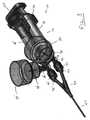
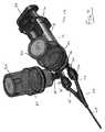
装填カップを使った2パート送達シリンジが図に示されている。このような送達シリンジが本発明で使用されてもよい。2パート送達装置10は、一般的には、ヘッドピース12、アプリケータ40、及び送達流路44を含む。ヘッドピース12、アプリケータ40、及び送達流路44のそれぞれは、互いに流体連通しており、使用中は液密な接続によって互いに堅固に接続されている。送達シリンジ10は、概して縦長形状であり、近位端10A及び遠位端10Bを含む。ヘッドピース12は、少なくとも1つの、望ましくは多数の円筒状又はチューブ状の胴部又はリザーバ18を含み、その中に送達されるべき材料又は複数材料が、送達までの間に貯蔵されてもよい。胴部18は、任意の構成で配置されてもよく、好ましい実施形態では、それぞれの長手方向軸が互いに平行で、近位端10Aから遠位端10Bの方向に延在する並んだ配向である。それぞれの胴部18は、同じサイズと形状であってもよく、又は異なるサイズであってもよい。いくつかの実施形態では、2つの胴部18を含み、それぞれが異なった容積で、それによってそれぞれの胴部18から同時に異なった量の流体の解放を可能とすることが望まれ得る。それぞれの胴部18は、その遠位端に出口ポート14を含み、それを通した流体の流れが起こってもよい。ヘッドピース12は、使用を容易にするために、近位端にハンドル16を含んでもよい。 A two-part delivery syringe using a loading cup is shown in the figure. Such a delivery syringe may be used in the present invention. The two-
それぞれの胴部18は、スライド可能にそれぞれの胴部18内に挿入されたプランジャ20などの、被制御の送達構成要素を含む。プランジャ20の遠位端は、内容物を胴部内外に押し引きするための胴部18の内面と接触する放射状シール又はピストン22を含む。それぞれのプランジャ20は、プランジャ圧迫具24を近位端に含み、これは使用者によってプランジャ20に力を加え、胴部18内へと(遠位端10Bの方向に押して)、及び胴部18から外へと(近位端10Aの方向に引いて)、操作される。装置10のそれぞれのプランジャ20は、プランジャ圧迫具24において、又はその近傍で、互いに連結されてもよく、したがってそれぞれのプランジャ20が、同時に胴部18の中に押され、又はそこから引き出されてもよい。 Each barrel 18 includes a controlled delivery component, such as a
ヘッドピース12は、それぞれの胴部18が送達流路44と流体連通したアプリケータルーメン42と流体接続するように、取り付け機構によって取り外し可能にアプリケータ40に連結されてもよい。スナップ嵌合、摩擦嵌合、ねじ連結、又は類似のものを含む任意の公知の取り付け機構を使用してもよい。望ましくは、ヘッドピース12とアプリケータ40との間の取り付けは、実質的に液密である。以下に議論されるように、ダイバータ弁組立体25を伴う装填ポートは、望ましくはヘッドピース12とアプリケータ40との間に位置する。 The
送達流路44は、概して中空のチューブ状構造であり、アプリケータルーメン42と流体連通しており、また、そこに液密接続で堅固に取り付けられている。送達流路44は、多数のルーメンを含み、それぞれが1つのアプリケータルーメン42と流体連通していてもよい。送達流路44の先端は開放ノズルでもよいが、あるいは、へら、回転ボール、ブラシ、及び/又は綿棒などの添加手段を含んでもよい。任意の添加システムを使用してもよく、それらは米国特許第6、425、704号の記述を含み、その全文を参照により本明細書に組み入れるものとする。 The
使用中、使用者は、送達装置10に流体の装填を試み、及び/又は送達装置10の内部からの流体の分配を試みることがある。生体流体の送達の場合は、その成分の無菌状態を保つことが重要である。流体を送達装置10内に装填するために、装置10は少なくとも1つの装填ポートを備えていて、それは送達装置10の外側からヘッドピース12の内側までの、より具体的には、送達装置10の外側から胴部18の内部までの開放通路を生成する。本発明では、この開放通路は、ダイバータ弁組立体25の装填ポートを通して、ヘッドピース12の出口ポート14を経由して実現される。装填を実現するために、1つ又は複数のカップ34を使ってもよい。装填カップ34は、開放底部46への概して中空の内部ガイドを含み、開放底部には接続のためのねじが切られてもよい。装填カップ34は、更に伸長底部47を有してもよく、それはダイバータ弁組立体25の1つ又は複数の構成要素に向けての押圧に使われてもよい。装填カップ34は、所望により、スパイク38又は他の制御機能などの、流体の流れを開始し、制御し、制限する追加機能を含んでもよい。装填カップ34は、更に装填カップカバー36を備えてもよく、それは装填カップ34の上部に固定されてもよく、またそれは装填カップ34の内容物をカバーしてもよい。装填カップカバー36は、ビンが装填カップ34内に置かれるなら、ビンをカバーするサイズであってもよい。 During use, the user may attempt to load the
図5〜図6への特定の参照によれば、ダイバータ弁組立体25の1つの実施形態が表示される。ダイバータ弁組立体25は、装填カップ34を装置10に取付けることができ、それによって装填カップ34の内部から胴部18の内部までの開放通路が生成されるように、装填カップ34の一部を受容するサイズと形状である。ダイバータ弁組立体25は、概して開放の弁本体26を含み、その内部には弾力のあるダイバータ構成要素28(「弁構成要素」とも称する)が配置される。ダイバータ構成要素28の頂部には、概してチューブ状の弁キャップ30が設置され、弁キャップはそこへの装填カップ34の固定を実現するためのねじ山を任意選択で有してもよい。弁キャップ30と弁本体26は、実質的に液密な嵌合を生成する任意の手段によって互いに固定できてもよい。ダイバータ弁組立体25は、概してチューブ状のヘッドピース嵌合27をも含み、ヘッドピース嵌合は出口ポート14を、そことの流体連通にて、摩擦嵌合又は他の固定連結によって固定するために使われてもよい。ダイバータ弁組立体25は、概してチューブ状のアプリケータ嵌合29をも含んでもよく、アプリケータ嵌合はアプリケータルーメン42をそことの流体連通にて固定するために使われてもよい。弁本体26は、流体が流れることができる(例えば、ヘッドピース嵌合27を通して、又はアプリケータ嵌合29を通して)複数方向の開口を有する概して開放構成であり、したがって、ダイバータ弁組立体25が流体の流れ方向を制御する。チューブ状のアプリケータ嵌合29は、概してチューブ状のルアー嵌合32をも含んでもよく、ルアー嵌合は、それとの流体連通でアプリケータルーメン42をそこに取り付けるために使われてもよい。 With particular reference to FIGS. 5-6, one embodiment of the
装填カップ34は、ダイバータ弁組立体25に、具体的には弁キャップ30に、任意の所望の公知の固定手段によって固定されてもよく、固定手段には、チューブ状弁キャップ30内に又はその上にねじ締めするように、ねじ山の使用を含んでもよい。装填カップ34は、望ましくは底部46を含み、底部は、チューブ状弁キャップ30のねじ部と嵌合するようなサイズと形状の一連のねじ山を含む。弁キャップ30は、雌ねじ又は雄ねじを含んでもよく、また装填カップ34は、弁キャップ30と係合するねじ山を含んでもよい。装填カップ底部46及び任意選択の伸長底部47は、開放ルーメンを有する概してチューブ状であり、装填カップ34の内部からチューブ状弁キャップ30まで、したがって弁本体26内までの流体の流れを可能とする。伸長底部47は、概して円筒状でもよいが、任意の所望の形状でもよい。図5に見られるように、ヘッドピース12内への流体の送達は、ビン48を用いて実現されてもよい。1つのビン48が1つの送達カップ34と共に使われてもよい。どのようなビン48が使われてもよく、望ましくはビンはガラスであり、ゴム又はプラスチックの隔膜で蓋をされている。装填カップ34は、望ましくはビン48の隔膜49を穿孔する通気スパイク38を備え、ビン48の流体内容物を、無菌状態でかつ管理された状態で、ビン48から引き出すことを可能とする。ビン48が装填カップ34内に装填されるときに、スパイク38が隔膜49のほぼ中央に確実に当たるように、隔膜49の軸がスパイク38と整列すべく装填カップ34の底部には幾何形状が設けられる。装填位置にあるとき、装填カップカバー36が、ビン48の頂点を覆って設置されてもよく、それによって装填に更なる安全性と無菌状態とを提供してもよい。装填カップ34は、チューブ状弁キャップ30に固定され、少なくともその一部は流体によって、例えばビン48内に含まれる流体によって、満たされてもよい。次いで使用者は、プランジャ20をダイバータ弁組立体25に連結した胴部18から引き、これによって、流体を装填カップ34内の薬ビン48から、装填カップ34の底46を通して、チューブ状弁キャップ30を通して、ダイバータ構成要素28を過ぎて、弁本体26内へ、チューブ状ヘッドピース嵌合27を通して、出口ポート14を通して、胴部18内に引き込んでもよい。装填カップ34は取り除かれてもよく、所望により、任意選択のキャップ又はカバーをチューブ状弁キャップ30上に設置してもよい。 The
図6A〜図6Bに、ダイバータ弁組立体25のクローズアップ図を示す。図に見られるように、ダイバータ弁組立体25は弁本体26を含み、弁本体は多数の出口ポートを有する概して中空構成であり、出口ポートは、チューブ状のヘッドピース嵌合27(ヘッドピース12へと導く)、及びチューブ状のアプリケータ嵌合29(アプリケータルーメン28へと導く)を含む。弁本体26の内部は、ダイバータ構成要素28にぴったり嵌合するサイズと形状であり、ダイバータ構成要素28の頂部には、チューブ状の弁キャップ30が配置されている。弁キャップ30と弁本体26は、ねじ、スナップ嵌合、摩擦嵌合、及び類似のものを含む任意の所望の方法で、互いに固定され得る。以下に説明するように、ダイバータ弁組立体25に加わる圧力のレベルによって、ダイバータ構成要素28は「下方へ」(例えば弁本体26の底に向けて)押されることもあり、又は「上方へ」(例えばチューブ状弁キャップ30に向けて)押されることもある。例えば、装填カップ34がダイバータ弁組立体25に固定されると、ダイバータ構成要素28が「下方に」押され、それによってダイバータ弁組立体25が「装填構成」となってもよい。装填構成は図10にて最もよく見ることができる。装填カップ34が取り外されると、ダイバータ構成要素28が「上方に」付勢され、それによってダイバータ弁組立体25が「分配構成」となってもよい。分配構成は図11にて最もよく見ることができる。1つの実施形態では、装填カップ34の伸長底部46は、ダイバータ弁組立体25に圧力をかけるために使用さてもよく、これについて以下により詳細に記述する。 A close-up view of the
流体をヘッドピース12内に装填するには、装填カップ34から胴部18に(ダイバータ弁25を経由して)導かれる流路が開放されなければならず、胴部18からアプリケータルーメン42に導かれる流路が閉塞されなければならない。流体を分配するには、装填カップ34から胴部18に導かれる流路が閉塞されなければならず、胴部18からアプリケータルーメン42に導かれる流路が開放されなければならない。この切換えは、伝統的には、手動弁又はスイッチの使用によって実現されていて、これらは間違いを起こしやすい。ひとたび分配流路が開放されると、使用者が1つ又は複数のプランジャ20を押し、望ましくはそれぞれのプランジャ20を同時に押し、胴部(1つ又は複数)18の内容物が、圧力のもとにアプリケータ40を通して送達流路44の外に押し進められる。したがって、混合された組成物を所望の位置に送達することができる。マルチパートシリンジは、ある生体材料とシーラント材料のように、送達前に即時に成分を混合する必要のある組成物の送達に有効である。例えば、装置10はフィブリンを分配することもあり、フィブリンは2つの成分(トロンビンとフィブリノーゲン)の、最終成分の分配前の即時の混合を必然的に伴う。混合はそれぞれの流体の送達流路44からの分配に次いで即時に行われ得る。装置10は、装置10の内部を保護するように、どの開放構成要素の上にも1つ又は複数のシール又はキャップを含んでもよい。 In order to load fluid into the
上述した種々の構成要素は、任意の所望の材料から作られてもよく、最も望ましくは、材料が生物学的に安定で不活性である。具体的には、装置10の構成要素は、そこから分配される流体とは実質的に非反応性であるべきである。例えばプラスチック、エラストマー材料、ガラス、金属、及びそれらの組合せから、種々の構成要素が作られてもよい。それぞれの構成要素は可撓性、非可撓性、準剛性、剛性、又は補強物であってもよいが、しかしながら、ダイバータ構成要素28の少なくとも一部は、十分に可撓性で、圧縮と移動が可能であるべきである。いくつかの実施形態では、ダイバータ構成要素28を第1又は第2の方向に押しつけるため、又は付勢するために、ばねシステムが備えられてもよく、このような実施形態では、ダイバータ構成要素28はより強固であってもよい。 The various components described above may be made from any desired material, most desirably the material is biologically stable and inert. In particular, the components of
本発明は、標準的な送達システムを、ダイバータ弁組立体25を組み込むことで改良するものであり、ダイバータ弁組立体は、システムを手動で切換える必要なく、「分配構成」から「装填構成」へと(その逆も同じく)自動的に切り替わる。 The present invention improves upon a standard delivery system by incorporating a
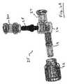
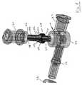
望ましくは、少なくとも2つの異なる装填カップ34を使用して、送達装置10の少なくとも2つの胴部18を満たす。例えば図2〜図4は、2パートシステムにおける装置10を示す。すなわち、例えば、2つの胴部18、18’、及びその中に含まれる2つのプランジャ20、20’が存在する。それぞれの胴部18、18’は、それ自体の出口ポート14、14’と連結し、出口ポートはそれ自体のダイバータ組立体(例えば、弁本体26、26’;チューブ状ヘッドピース嵌合27、27’;チューブ状アプリケータ嵌合29、29’;ダイバータ構成要素28、28’;チューブ状弁キャップ30、30’)と連結されている。それぞれのダイバータ弁組立体25は、それ自体の装填キャップ34、34’と連結され、装填カップはそれ自体のカバー36、36’と連結されてもよい。それぞれのダイバータ弁組立体25は、1つのアプリケータルーメン42、42’との流体連通にてアプリケータ嵌合29を接続するように、任意選択のルアー嵌合32、32’を含んでもよい。アプリケータルーメン42、42’は送達出口44へ至り、そこで流体が分配される。送達装置10は任意の数の構成要素を含んでよいが、代表表示の目的のため、2パート送達装置が示されている。 Desirably, at least two different loading cups 34 are used to fill at least two barrels 18 of
例えば、2パート構成では、第1の流体材料は第1の装填カップ34内に装填され、第2の流体材料は第2の装填カップ34’内に装填される。それぞれの流体材料は、ビン48を通して供給されてもよく、上記で説明したように、ビンはスパイク38によって穿孔される隔膜49を有する。材料は任意の所望の材料であってもよく、好ましい実施形態では、材料は流体である。所望により、材料又は複数の材料は、第1又は第2の装填カップ34、34’内に装填される前に再構成されてもよい。装填前に、プランジャ20、20’が、それぞれの胴部18、18’内に所望の長さだけ押し込まれ、装填カップ34、34’が装置10に固定される。望ましくは、装填カップ34、34’が底部46上のねじ山によって固定されるが、任意の公知の固定手段を使用してもよい。装填カップ34が装置10に固定されるときに、装填カップ34の開放内部は、ダイバータ弁組立体25を経由して少なくとも1つの胴部18と流体連通している。次にプランジャ20が使用者によって近位方向に(10Aに向けて)引かれ、これによって装填カップ34の流体内容物が、連結されている胴部18内に引かれる。望ましくは、第1の装填カップ34が第1の胴部18を満たすために使われ、第2の装填カップ34’が第2の胴部18’を満たすために使われる。所望の量の材料が胴部18、18’に満たされると、装填カップ34、34’は取り除かれてもよく、キャップ又はカバーが任意選択で送達弁組立体25の装填ポートを覆って設置されてもよい。胴部18、18’内に含まれる流体と、近位に引かれるプランジャ20、20’とによって、装置10は十分に装填されて、組成物の送達が準備される。 For example, in a two-part configuration, the first fluid material is loaded into the
図7は、本発明の、装填カップ34がそこに固定されたダイバータ弁組立体25の構成要素を示す。固定された装填カップ34を伴って、ダイバータ弁組立体25は「装填構成」に置かれている。ダイバータ弁組立体25は、上記で説明した送達シリンジを含む任意の送達装置と共に使用されてもよい。本明細書で記述した実施形態では、組立体は2つのダイバータ弁システム(例えば2つの材料の装填用に)を含むことになるが、本組立体を通して、任意の数の成分を送達してもよいことが理解される。望ましくは、それぞれのダイバータ弁組立体25は、単一の胴部18と流体連通しているが、所望により、2つ以上のダイバータ弁組立体25が1つの胴部18と流体連通していてもよい。本質的には、ダイバータ弁組立体25は、それぞれ装填カップ34から装置10の内部への、より具体的にはヘッドピース12の内部への、最も具体的には胴部18の内部への入り口としてそれぞれ働く。ダイバータ弁組立体25は、また、それぞれ胴部18からアプリケータ40への入り口として働く。 FIG. 7 illustrates the components of the
弁キャップ30は、概してチューブ状構成であり、それは所望により先細りでもよく、その開放内部を通して流体の流れを可能とする。チューブ状弁キャップ30は、先細りの底部を含み、それは弁本体26にぴったり嵌合するサイズであり、それらの間に流体連通を提供する。チューブ状弁キャップ30は、堅固に、取り外し不可能に弁本体26に取り付けられてもよく、又は、チューブ状弁キャップ30は、所望によりダイバータ弁組立体25からは取り外し可能であってもよい。いくつかの実施形態では、例えば、チューブ状弁キャップ30は、接着剤又は別の固定手段によって装置10に固定されてもよい。チューブ状弁キャップ30が取り外し可能な実施形態では、チューブ状弁キャップ30の弁本体26への取付けは、例えばスナップ嵌合、摩擦嵌合、ねじ嵌合、又は類似のものを含む任意の所望の手段で実現されてもよく、その手段は、弁本体26をチューブ状弁キャップ30の底部に接合するサイズと形状を有するものである。チューブ状弁キャップ30は、既に説明したように、装填カップ34に固定されるように、関連する取り付け手段を含んでもよい。 The
チューブ状キャップ30の開放端は、キャップ又は他のカバー(図示せず)などの閉塞手段を任意選択で含み、装填構成にないときに装置の内部を保全してもよい。図7のように組立てられると、装填カップ34内部から、その底部46を通り、チューブ状弁キャップ30を通して、弁本体26内に至る開放流路が存在する。弁本体26から、ヘッドピース嵌合27及びアプリケータ嵌合29の2つの開口が存在する。ダイバータ弁組立体25は、いずれの開口を通して流体を流すかを制御するために使用される。 The open end of the
本発明の流体の流れのこの制御は、ダイバータ構成要素28の使用によって実現され、ダイバータ構成要素は、弁本体26とチューブ状キャップ30との間の位置に固定されるサイズと形状であり、流体の種々の方向の流れを制御する。ダイバータ構成要素28は、弁本体26に取り付けられてもよく、クリーニング又は包装を実施するために任意選択で取り外し可能としてもよい。ダイバータ構成要素28は、固定取り付け具なしで弁本体26内に単に挿入されてもよく、これは、使用していないときの簡単な取り外しの一助となる。ダイバータ構成要素28は、弁本体26の底を貫通し、ダイバータ構成要素28内に延在するピン又は穴の使用によって所定の位置に保持されてもよい(図示しない)。ダイバータ弁組立体25に出入りする流体が図10及び図11に見られ、以下に更に詳細に説明されることになる。 This control of fluid flow of the present invention is achieved through the use of a
ダイバータ構成要素28は、所望の任意の材料から作られてもよく、いくつかの実施形態では、それはプラスチック、ゴム、金属、及びそれらの組合せから作られてもよい。望ましくは、ダイバータ構成要素28は、プラスチック、シリコーン、又はエラストマーゴムなど、装置10の嵌合とシールを支援する、弾性で変形可能な材料から作られる。ダイバータ構成要素28は、圧縮可能な底部又は側部などの1つ又は複数の圧縮可能な領域を含み、弁本体26に加えられて、ダイバータ構成要素28を「上」又は「下」位置へ付勢する力を可能としてもよい。ダイバータ構成要素28は、所望により、弾性の外部コーティング又は被覆を含んでもよい。ダイバータ構成要素28は、弁本体26とチューブ状弁キャップ30との間の開口にぴったりの嵌合を形成するようなサイズと形状である。いくつかの実施形態では、ダイバータ構成要素28は、概して平坦な、ディスク状の形状であってもよく、その上面又は底面上のばねの使用などによって、「上」又は「下」の位置に付勢されてもよい。すなわち、ダイバータ構成要素28はディスクであってもよく、ばね又は他の付勢構成要素の使用によって「上」構成へと付勢され、装填カップ34の取り付けなどによる力を加えることで「下」へ付勢される。別の実施形態では、ダイバータ構成要素28は、外側に向けて延在するディスクのようなフランジを伴い、中間部(すなわち第1の端部と第2の端部との間)に延在する概して円筒状の形状を含んでもよい。 The
図8に最もよく見られるように、1つの実施形態では、ダイバータ構成要素28は、延在する円筒状フランジ部100を伴う概して円筒状の構成を含み、フランジ部は概して円筒状の下部104と概して円筒状の上部106との間に位置する。上部106は、フランジ部100の上の近位に配置された一連の垂直リブ102を含んでもよい。リブ102は、組立体上半部のダイバータ構成要素28の軸方向のアラインメントを、その中の流体の流れを妨げずに保つために有効である。上部106の頂部は、その中に流路108を含んでもよく、流路はその中の流体の流れを可能とする。フランジ部100は、いずれも実質的に平坦な下面110及び上面112を含む。フランジ100は、変形可能で弾性であってもよい。下面110は、弁本体26の実質的に平坦な面114に接続するサイズと形状である。下面110が弁本体26の平坦面114に向かって圧縮されると、液密のシールが生成され、ダイバータ弁組立体25は「装填構成」である。同様に、上面112は、チューブ状弁キャップ30の実質的に平坦な面116に接続するサイズと形状である。上面112がチューブ状弁キャップ30の平坦面116に向かって圧縮されると、液密のシールが生成され、ダイバータ弁組立体25は「分配構成」である。任意選択で、弁本体26とダイバータ構成要素28の底端部は、開放チューブ構成を有してもよく、これによって、弁本体26の底に、及びダイバータ構成要素28の底内部へ、ピン又は穴(図示せず)の挿入が可能となる。このことは、組立てられたときの構成要素の軸方向のアラインメントと、その維持を可能とし得る。ピン又は穴(図示せず)の使用は、ダイバータ構成要素28のスムーズな圧縮と変形を可能とし、フランジ100の形状の移動を可能とし得る。ダイバータ構成要素28の底は、力の存在で圧縮性となり得るが、そこに作用する外力がなければ伸長し得る。圧縮性の底は、ダイバータ構成要素25を「分配」構成に付勢するのに有効であり得る。いくつかの実施形態では、別のばね装置をダイバータ構成要素28の底に設置し、他の力がそこにないとき、ダイバータ構成要素28を分配構成に向けて付勢してもよい。 As best seen in FIG. 8, in one embodiment, the
図9は、本発明において有効となり得る代替の実施形態を示す。図9を参照すると、その実施形態は、概して円筒状の中間部122、円筒状の上部132、及び円筒状の下部124を含むダイバータ構成要素120を含む。ダイバータ構成要素120は、円筒状の中間部122と円筒状の下部124との間に配置された円錐状の下部126を含む。ダイバータ構成要素120は、円筒状の中間部122と円筒状の上部132との間に配置された円錐状の上部128を含む。円筒状の底部124は、任意選択で、力の存在で圧縮性となり得るが、そこに作用する外力がなければ伸長し得る。圧縮性の底124の使用は、弁本体120に作用する力がない状態で装置が分配構成に付勢されるべき場合に有効であって、例えば、装填カップ34が装置10に固定されていないとき、弁本体120は分配構成に付勢されている。それぞれの円錐部(126/128)の角度は所望により修正され、それぞれ弁本体26の実質的な平坦面114、又はチューブ状弁キャップ30の実質的な平坦面116に対して適切な液密シールを生成してもよい。いくつかの実施形態では、この角度は約45度であるが、円筒状の中間部122の外面に関しての計測で、約30度〜約60度の間の任意の角度であってもよい。上部132は、その中に流路130を含んでもよい。 FIG. 9 illustrates an alternative embodiment that may be useful in the present invention. Referring to FIG. 9, the embodiment includes a diverter component 120 that includes a generally cylindrical intermediate portion 122, a cylindrical
ダイバータ構成要素28は、使用すべき装置10のサイズによって決まる任意の所望のサイズであってもよい。いくつかの実施形態では、例えば、上部106の長さは、ダイバータ構成要素28の頂部からフランジ部100までの計測で、約3〜約10mmであってもよい。フランジ部100は、軸方向の長さ約1mm〜約10mm(上面110と下面112との間の計測)を有してもよい。下部104の長さは、フランジ部100から底までの計測で、約3mm〜約15mmであってもよい。フランジ100の直径は、任意の所望のサイズであってもよく、いくつかの実施形態では、約5mm〜約20mmである。 The
ダイバータ構成要素28は、ダイバータ構成要素28が装置10の内部の方向の「下へ」(例えば弁本体26に向かって)押されてもよく、又は、装置10の外部の方向の「上へ」(例えばチューブ状弁キャップ30に向かって)押されてもよいように、弁本体26及びチューブ状弁キャップ30とスライドできるように連結されている。言い換えれば、ダイバータ構成要素28は、装置10に出入りする流体の流れを切換えるのに有効となる程度に、「上に」又は「下に」押されてもよい。ダイバータ構成要素28はチューブ状弁キャップ30の方向に、したがって分配構成に、付勢されてもよい。付勢は、例えば圧縮性の底の使用、又は上に説明したピン/穴システムによるものを含む任意の手段にて実現してもよい。ダイバータ構成要素28は、装填カップ34をダイバータ弁組立体25に固定することで「下に」押されてもよく、いくつかの実施形態では、装填キャップ34の伸長底部47が物理的にダイバータ構成要素28に当接して、それを「下の」位置へ付勢してもよい。 The
図10及び図11は、それぞれ「装填構成」及び「分配構成」にある本発明のダイバータ弁組立体25を示す。ダイバータ構成要素28は、任意の押圧手段によってどちらの方向にも押圧され得る。既に説明したように、ダイバータ弁組立体25は望ましくは自動化されて、それによって、使用者による手動操作なしで、「装填構成」(図10)から「分配構成」(図11)への自動的な操作を可能とする。これは、ねじが切られた底部46と伸長底部47を有する装填カップ34の使用によって最もよく実現される。装填カップ34が、それぞれのねじ山で共にねじ締めされるなどによって、チューブ状弁キャップ30に固定されると、底部46又は伸長底部47が、ダイバータ構成要素28を「下」へ、装置10の中へ押し込む。ダイバータ構成要素28は組立体内部にスライド可能に配置されているので、ダイバータ構成要素28を、弁本体26に向かって押すことができ、それによって装填カップ34から胴部18の内部への流路が生成されることになる。 10 and 11 show the
図10に見られるように、「装填構成」では、フランジ100の下面110が弁本体26の平坦面114に向けて押圧され、それらの間の液密シールが生成される。同時に、フランジ100の上面112が、チューブ状弁キャップ30の平坦面116から離れ、流体流路又は流れ経路が生成される。流体流れ経路は矢印で示され、始点54(例えば装填キャップ34内)から始まり、ダイバータ弁組立体25を通り、終点56(例えば胴部18内)で終了する。装填の流体流れ経路(始点54、終点56)は、装填カップ34から出て、装填カップ底46を通過し、弁キャップ30を通り、ダイバータ構成要素28を通過して、弁本体26内へ、ヘッドピース嵌合27を通り、出口ポート14を通して胴部18内に至る。 As seen in FIG. 10, in the “loading configuration”, the lower surface 110 of the
図11に見られるように、「分配構成」では、フランジ100の下面110が弁本体26の平坦面114から離れ、流体流路又は流れ経路が生成される。同時に、フランジ100の上面112が、チューブ状弁キャップ30の平坦面116に向かって押圧され、それらの間に液密シールが生成される。分配流体流れ経路は矢印で示され、始点50(例えば胴部18内)から始まり、ダイバータ弁組立体25を通り、終点52(例えば送達流路44から外へ)で終了する。分配流体流れ経路(始点50、終点52)は、胴部18から出て、出口ポート14を通り、弁本体26に入り、ダイバータ構成要素28を過ぎて、アプリケータ嵌合29を通って、アプリケータルーメン42に至る。明らかに、図11の分配構成では、装填カップ34はチューブ状弁キャップ30に取り付けられていない。したがって、ダイバータ構成要素28に働く「下向きの」圧力は存在しない。ダイバータ構成要素28は「上向き」構成に付勢されているので、ダイバータ構成要素28は、「分配構成」にある。 As seen in FIG. 11, in the “distribution configuration”, the lower surface 110 of the
装置10の装填の詳細がここで説明される。「装填構成」では、流体は、装填カップ34から、チューブ状弁キャップ30を通り、ダイバータ構成要素28を過ぎ、弁本体26を通って、ヘッドピース出口ポート14を通り、装填カップ34と流体連通している胴部18に入るように流れることができる。既に説明したように、「装填構成」では、装填カップ34が引き起こす圧力のもと、ダイバータ構成要素28が押圧され、フランジ100と弁本体26の平坦面114との間にシールが形成され、アプリケータ嵌合29への経路を遮断する。しかしながら、この「装填構成」では、ダイバータ構成要素28の上部に流路が存在し、流体の流れを可能とする。流路は、そこでの流体の流れを許容するに十分な、任意の所望のサイズとしてもよく、いくつかの実施形態では、フランジ100の面から弁キャップ30の平坦面116までの計測で、約1mm〜約50mmと測定される。 Details of loading the
「装填構成」における流体の流れは、図10の、54で開始して56で終わる装填経路矢印で表される。これが、使用者に胴部18を流体で満たすことを許容する。再び「装填構成」において、フランジ100の下部110は、弁本体26の平坦部114に向けて強く押圧されているので、液密シールを生成してアプリケータ嵌合を遮断し、したがって、アプリケータ40には、又はアプリケータ40から、流体が流れることがない。したがって、「装填構成」では、使用者が近位方向にプランジャ20を引くと、流体は経路に沿って、始点54から終点56まで、そして胴部18内に流れる。フランジ100と弁本体26の平坦部114のシールによって、流体は、アプリケータ嵌合29から近位方向(例えばアプリケータ40に向かって)には流れない。使用者は、この構成で流体を胴部18内に装填することができる。 The fluid flow in the “loading configuration” is represented by the loading path arrows beginning at 54 and ending at 56 in FIG. This allows the user to fill the torso 18 with fluid. Again in the “loading configuration”, the lower portion 110 of the
胴部18から送達流路44への流体の分配がここで説明される。装置10は、「装填構成」から「分配構成」への切換えを、本発明の自動ダイバータ弁組立体25によって迅速に、簡単に、及び確実に行うことができる。「分配構成」では、装填カップ34が取り除かれ、ダイバータ構成要素28がチューブ状弁キャップ30の方向に押される。いくつかの実施形態では、どのような外力もなければ、装置は分配構成に付勢されている。このような付勢は、圧縮性の底、ないしは、その底側又はシールフランジ100の下に設置されたばねなどの圧縮性要素の使用によって実現される。したがって、ダイバータ構成要素28に働く外力がなければ、ダイバータ構成要素28は、チューブ状弁キャップ30の方向に付勢されてもよい。 The distribution of fluid from the barrel 18 to the
図11に見られるように、「分配構成」では、フランジ100の上部112がチューブ状弁キャップ30の平坦部116に向けて堅固に押圧され、それら2つの間に液密シールが生成される。同時に、ここでは、フランジ100の下部110と、弁本体26の平坦面114との間に流路が存在する。この流路は、図11にて始点50及び終点52で表され、胴部18からアプリケータ40を通り、送達流路44から外への流体の流れを許容する。流路は、そこでの流体の流れを許容するに十分な任意の所望のサイズとしてもよく、いくつかの実施形態では、フランジ100の面から弁本体26の平坦面114までの計測で、約1mm〜約100mmと測定される。使用者は、単にプランジャ20を押して、流体を胴部18の外へ、ダイバータ弁組立体25を通して、アプリケータ嵌合29を通し、アプリケータルーメン42から外へ出す。 As seen in FIG. 11, in the “distribution configuration”, the upper portion 112 of the
フランジ100の面110、112、並びに弁本体26の平坦面114及びチューブ状弁キャップ30の平坦面116は、互いに対してぴったりと押圧されると液密シールを形成することになる材料から作られるべきである。材料は、同じであってもよいし、異なってもよい。望ましくは、送達される流体が、これらの構成要素との接触で汚染されないように、材料は生物学的に安定で不活性である。例えば、材料として、プラスチック、ゴム、金属、ガラス、及びこれらの組合せであってもよい。ガスケット又は他の追加のシール機能が、1つ又は複数の面上に含まれてもよい。 The faces 110, 112 of the
したがって、ダイバータ構成要素28は、3つの通路のうちの少なくとも1つに沿う流体の流れを供給又は遮断するために有効である。第1の通路は、チューブ状弁キャップ30とダイバータ構成要素28との間(例えば平坦面116とフランジ100との間)に位置する。第2の通路は、ダイバータ構成要素28とヘッドピース出口14との間に位置し、ヘッドピース嵌合27を経由する。したがって、第2の通路は、胴部18に入る流体の流れを可能とする。第3の通路は、ダイバータ構成要素28とアプリケータ40との間に位置し、アプリケータ嵌合29を経由する(フランジ100と平坦面114との間)。したがって、第3の通路は、胴部18からアプリケータ40への流体の流れを可能とする。 Thus, the
「装填構成」では、装填経路(始点54、終点56)は第1の通路と第2の通路を流体接続し、したがって、流体を装填カップ34から胴部18へと導く。装填経路は、任意の所望の長さ又は幅を有してもよく、それを通過する流体の流れを許容するに十分となるように、幅は約1mm〜約100mmでもよい。装填構成では、第3の通路は遮断されている。 In the “loading configuration”, the loading path (start
「分配構成」では、分配経路(始点50、終点52)が開放され、第2の通路及び第3の通路と流体接続されて、したがって、胴部18からアプリケータ40への流体の流れを可能とする。分配経路は、任意の所望の長さ又は幅を有してもよく、それを通過する流体の流れを許容するに十分となるように、幅は約1mm〜約100mmでもよい。分配構成では、第1の通路は遮断されている。 In the “distribution configuration”, the distribution path (start point 50, end point 52) is open and fluidly connected to the second and third passages, thus allowing fluid flow from the barrel 18 to the
本発明は、装置10を送達される流体で装填する方法だけではなく、装置10が装填された後に流体を分配する方法をも提供する。1つの実施形態では、既に説明したように、装置10には当初は送達されるべき流体が実質的に存在しなくてもよい。装置10は、以前には流体の送達に使用されたことがなくてもよく、又は送達する流体が実質的にない状態となるように、クリーニング及び/又は殺菌されてもよい。本明細書で使用される「実質的にない」は、クリーニング又は殺菌のあとに残留した任意の流体などの、少量の流体の存在は可能としている。どのような送達すべき流体又は複数の流体でも使用でき、それらは液状形態の流体、ガス、プラズマ、及びそれらの組合せを含む。1つの実施形態では、送達される流体はシーラント材料でもよく、フィブリンのようなマルチパートシーラント材料であってもよい。フィブリンの送達は、2つ個別の生体流体、フィブリノーゲンとトロンビン、の混合と分配を必要とする。装置10の装填は、それぞれの流体の別々の胴部18内への装填を含んでもよい。したがって、装填前の状態では、装置10には実質的にフィブリノーゲン及び/又はトロンビンは存在しない。本発明では、例えばアクリレートのような、別の単一又はマルチパート流体組成物を送達してもよい。装置10が前もって使用されていたら、どちらかの組成物の痕跡量が存在し得る。 The present invention provides not only a method for loading the
本方法は、材料の装填と分配の両方を含む。本明細書の議論は、第1の流体と第2の流体とを含む2パート組成物の装填と送達を必然的に伴うことになるが、本明細書で説明される方法は、単一パート組成物又は3つ以上の異なる成分を伴う組成物の装填と送達に使用できることも理解されることになる。2パート組成物に対して、装置10は、ヘッドピース12内に位置する2つの胴部18、18’を含み、しかし更に、3つ以上の異なる流体が送達される場合には、3つ以上の胴部18が含まれてもよい。装置10は、それぞれの胴部18に1つのダイバータ弁組立体25を含み、それぞれの胴部18に1つのアプリケータルーメン42を含む。 The method includes both loading and dispensing of material. Although the discussion herein will entail the loading and delivery of a two-part composition comprising a first fluid and a second fluid, the method described herein is a single part. It will also be appreciated that the composition or compositions with more than two different components can be used for loading and delivery. For a two-part composition, the
まず本方法は、送達されるべき流体での装置10の装填に関する。装填前の状態では、装置10には装填されるべき流体は実質的に存在しない。望ましくは、ダイバータ弁組立体25のそれぞれのダイバータ構成要素28、28’は分配構成に付勢されている。使用者は、胴部内の流体が排出されて胴部が満たされる用意が整うように、それぞれのプランジャ20、20’をそれぞれの胴部18,18’内の所望のレベルまで押圧する。次に装填カップ34、34’が装置10に固定される。好ましい実施形態では、構成要素のねじが切られた組立体などによって、単一の装填カップ34が単一のバルブキャップ30に固定される。したがって、それぞれのバルブキャップ30は、そこに固定された1つの装填カップ34を含む。 First, the method relates to
装填カップ34がチューブ状弁キャップ30上に固定されると、カップの底46又は伸長底部47が組立体と当接し、ダイバータ構成要素28を弁本体26内に付勢する。ダイバータ構成要素28の動きによって、第1のダイバータ弁組立体25が「装填構成」へと置かれ、これによって第1の装填カップ34内と第1の胴部18との間に流体連通を生成する。同様に、第2の装填カップ34’が組立体に固定され、第2の組立体が「装填構成」へと置かれる。次に、ビン48の挿入とスパイク38による隔膜49の穿孔などで、第1の装填カップ34が、第1の流体で所望の量に満たされてもよい。第2の装填カップ34’は、異なるビン48を通して、第2の流体材料で所望の量に満たされてもよい。第1及び第2の流体材料は、同一の材料でもよいが、望ましくは異なる材料で、これらが所望の反応生成組成物を提供するような互いに実質的に反応性である。1つの実施形態では、第1の流体材料はフィブリノーゲンであり、第2の流体材料はトロンビンである。第1の流体材料の所望の量は、第2の流体材料の所望の量と同じでもよく、又は異なってもよい。 When the
第1と第2の装填カップ34、34’内に収容された所望の量の第1及び第2の流体材料を伴い、また、それに連結された「装填構成」のダイバータ構成要素28を伴って、したがってそれぞれのカップ34、34’からそれに対応する胴部18,18’までの装填通路が生成され、使用者は、第1の流体及び第2の流体をそれぞれ第1及び第2の胴部18、18’内に導入するように、装置10のそれぞれのプランジャ18、18’を引いてもよい。胴部18、18’は、実質的に同量の材料で満たされてもよく、又は、それらは異なる量の材料を収容してもよい。例えば、第1の胴部18が、第2の胴部18’に収容されたトロンビンのような第2の材料の量より多量の、フィブリノーゲンのような第1の材料を含むことを所望されることがある。これは、異なる容積又は内径の胴部18を有することや、又は単に第1のカップ34を第2のカップ34’より少ない量の流体で装填することなどの、任意の所望の方法で実現できる。 With a desired amount of first and second fluid materials contained in first and second loading cups 34, 34 'and with a "loading configuration"
それぞれの胴部18に流体を導入する工程のあとに、装置10は装填状態となる。装填状態では、所望の量の第1及び第2の流体がそれぞれ第1及び第2の胴部18、18’内部に収容されていて、それらのそれぞれのプランジャ20、20’が、装置10の近位端10Aに向かって引かれている。装填カップ34、34’は、なお弁キャップ30、30’に固定されているので、ダイバータ構成要素28は、なお「装填構成」に付勢されている。この時点で、装填カップ34、34’を装置から任意選択で取り外してもよく、又は固定したままでもよい。所望により、装填カップ34、34’を覆うカバー又はシールを置いてもよい。代替え方法として、所望により、装填カップ34、34’を取り外し、1つ又は複数のカバー又はシールを弁キャップ30、30’の上に置いてもよい。 After the step of introducing fluid into each barrel 18, the
本発明はまた、装置10からの流体組成物の分配方法に関する。流体の分配を実現するために、まず装置10が「分配構成」に置かれなければならず、これは既に説明したように、また図11に見られるように、ダイバータ構成要素28の「分配構成」への移動を必然的に伴う。ダイバータ構成要素28の移動は任意の手段で実現でき、最も望ましくは、ばね、スイッチ、ピン、穴、又は付勢力、及び類似物などの自動化システムによって移動させる。ダイバータ構成要素28の移動は、装置10から装填カップ34、34’を単に取り外し、ダイバータ構成要素28の「分配構成」への付勢を可能とすることによって実現してもよい。「分配構成」では、分配通路(始点50、終点52)が開放され、胴部18内からそれと連結するアプリケータルーメン42との間の流体連通を許容する。分配構成では、装填通路は遮断され、胴部18から弁キャップ30への流体の流れは阻止される。 The present invention also relates to a method for dispensing a fluid composition from the
「分配構成」の間に、使用者は、次いで1つ又は複数のプランジャ20を押圧して、プランジャ20をそれと連結された胴部18を通して遠位方向に押し、これによってそれぞれの胴部18内に収容された流体を遠位方向に押してもよい。ダイバータ構成要素28は分配構成にあるので、分配通路が開放されていて、それぞれの胴部18からの流体は、ヘッドピース嵌合27を通して、それぞれのダイバータ構成要素28を過ぎて、それぞれのアプリケータ嵌合29を過ぎて、アプリケータルーメン42内へ流れることが可能であり、アプリケータルーメンにてそれぞれの流体が、送達流路44を通して分配されてもよい。送達流路44を通して分配されると、直ちに成分の混合が行われ得る。 During the “distribution configuration”, the user then presses one or
ヘッドピース12、アプリケータ40、胴部18、プランジャ20、弁本体26、弁キャップ30、ダイバータ構成要素28、及び装填カップ34を含む装置10の種々の構成要素は、所望により組立体からそれぞれ個別に取り外し可能とし、装置の包装又はクリーニングを可能としてもよい。本発明は、既に説明した装置10の構成要素を含むキットを更に含んでもよい。キットは、使用者に、組立て方法とその種々の構成要素の使用方法とを説明する使用説明書のセットを更に含んでもよい。もしくは、いくつかの構成要素は装置10に取外せないように固定されていてもよく、それによって使用者の簡便な取扱いと使用を提供できる。 Various components of the
〔実施の態様〕
(1) 三方ダイバータ弁組立体(three-way diverter valve assembly)を備える流体送達装置であって、前記三方ダイバータ弁組立体が、
(i)弁本体と弁キャップとを有し、それぞれアクセス開口を有する第1の流体通路と、第2の流体通路と、第3の流体通路と、を提供する、弁ハウジングと、
(ii)前記弁ハウジング内の弾性弁構成要素と、を備えており、
前記弾性弁構成要素が、第1の位置から第2の位置へ移動可能であり、前記第1の位置が前記第2の流体通路と前記第3の流体通路との間に流体経路を提供し、前記第2の位置が前記第1の流体通路と前記第2の流体通路との間に流体経路を提供する、流体送達装置。
(2) 前記弁ハウジング内の前記弾性弁構成要素が、第1の端部、第2の端部、及び前記第1の端部と第2の端部との間で外側に延在するフランジ、を有する、実施態様1に記載の流体送達装置。
(3) 前記弾性弁構成要素が、前記弾性弁構成要素に加えられる力に反応して、前記第2の位置から前記第1の位置へ移動する、実施態様1に記載の流体送達装置。
(4) 前記流体送達装置が、前記三方ダイバータ弁組立体、チューブ状胴部、及びアプリケータ、を備える、実施態様1に記載の流体送達装置。
(5) 前記弾性弁構成要素が、前記弁キャップ及び前記弁本体のうちの1つに固定される、実施態様1に記載の流体送達装置。Embodiment
(1) A fluid delivery device comprising a three-way diverter valve assembly, wherein the three-way diverter valve assembly comprises:
(I) a valve housing having a valve body and a valve cap, each providing an access opening, a first fluid passage, a second fluid passage, and a third fluid passage;
(Ii) an elastic valve component in the valve housing;
The resilient valve component is moveable from a first position to a second position, the first position providing a fluid path between thesecond fluid path and thethird fluid path. The fluid delivery device, wherein the second location provides a fluid path between thefirst fluid passage and thesecond fluid passage.
(2) The elastic valve component in the valve housing has a first end, a second end, and a flange extending outwardly between the first end and the second end. The fluid delivery device according to
(3) The fluid delivery device according to
(4) The fluid delivery device according to
5. The fluid delivery device according to
(6) 前記第2の通路が、前記弾性弁構成要素の面と前記チューブ状胴部との間の場所に位置する、実施態様4に記載の流体送達装置。
(7) 前記第3の通路が、前記弾性弁構成要素の面と前記アプリケータとの間の場所に位置する、実施態様4に記載の流体送達装置。
(8) 前記第1の通路が、前記弾性弁構成要素の面と前記弁キャップとの間の場所に位置する、実施態様4に記載の流体送達装置。
(9) 前記弾性弁構成要素が、エラストマー材料を含む、実施態様1に記載の流体送達装置。
(10) 前記弾性弁構成要素が、外力がないときには前記第1の位置に付勢される、実施態様1に記載の流体送達装置。(6) The fluid delivery device according to
(7) The fluid delivery device according to
(8) The fluid delivery device according to
9. The fluid delivery device according to
(10) The fluid delivery device according to
(11) 前記弁キャップに固定されるように構成された装填カップを更に含む、実施態様1に記載の流体送達装置。
(12) 前記装填カップが、前記弾性弁構成要素を押し、前記弾性弁構成要素を前記第2の位置に付勢する、伸長した底部を備える、実施態様11に記載の流体送達装置。
(13) 前記第1の位置が分配構成である、実施態様1に記載の流体送達装置。
(14) 前記第2の位置が装填構成である、実施態様1に記載の流体送達装置。
(15) 前記流体送達装置が、複数成分のアプリケータである、実施態様1に記載の流体送達装置。11. The fluid delivery device according to
12. The fluid delivery device of
(13) The fluid delivery device according to
14. The fluid delivery device according to
15. The fluid delivery device according to
(16) 前記流体送達装置が、第1のチューブ状胴部と、第2のチューブ状胴部とを備える、実施態様15に記載の流体送達装置。
(17) 前記第1のチューブ状胴部が第1のダイバータ弁組立体と流体連通しており、前記第2のチューブ状胴部が第2のダイバータ弁組立体と流体連通している、実施態様16に記載の流体送達装置。
(18) 流体送達装置を装填する方法であって、
(i)流体送達装置を使用することであって、前記流体送達装置が、
(1)少なくとも1つのチューブ状胴部を含むヘッドピースであって、前記チューブ状胴部が、前記チューブ状胴部の内部に設置されたプランジャを含む、ヘッドピースと、
(2)前記チューブ状胴部の前記内部と流体連通するルーメンを有するアプリケータと、
(3)前記少なくとも1つの胴部の内部及び前記アプリケータのルーメンの内部と流体連通する三方ダイバータ弁組立体であって、前記弁組立体が、
(i)弁本体と弁キャップとを有し、それぞれアクセス開口を有する第1の流体通路と、第2の流体通路と、第3の流体通路と、を提供する、弁ハウジングと、
(ii)第1の端部と、第2の端部と、前記第1の端部と前記第2の端部との間のフランジと、を有する、前記弁ハウジング内の弾性弁構成要素であって、前記弾性弁構成要素が、第1の位置から第2の位置へ移動可能であり、前記第1の位置が、前記第2の流体通路と前記第3の流体通路との間に流体経路を提供して前記胴部内部から前記アプリケータルーメン内部への流体の流れを可能とし、前記第1の位置が、前記第1の流体通路と前記第2の流体通路との間に流体経路を提供して前記弁キャップから前記胴部内部への流体の流れを可能とする、弾性弁構成要素と、を備える、三方ダイバータ弁組立体と、を備える、流体送達装置を使用することと、
(ii)開放内部及び底部の開口を有する装填カップを前記弁キャップに固定することであって、前記底部が前記弾性弁構成要素を前記第2の位置に付勢する、ことと、
(iii)前記装填カップの内部へ流体材料を配置することと、
(iv)前記流体材料を前記胴部の内部へ引き入れるように、前記胴部から前記プランジャを引出すことと、を含む、方法。
(19) 前記弁キャップが一連の雄ねじを備え、前記装填カップが一連の雌ねじを備える、実施態様18に記載の方法。
(20) 前記第2の通路が、前記弾性弁構成要素の面と前記チューブ状胴部との間の場所に位置する、実施態様18に記載の方法。(16) The fluid delivery device according to
(17) The first tubular body is in fluid communication with a first diverter valve assembly and the second tubular body is in fluid communication with a second diverter valve assembly. The fluid delivery device according to aspect 16.
(18) A method of loading a fluid delivery device comprising:
(I) using a fluid delivery device, wherein the fluid delivery device comprises:
(1) A head piece including at least one tubular body, wherein the tubular body includes a plunger installed inside the tubular body;
(2) an applicator having a lumen in fluid communication with the interior of the tubular body;
(3) A three-way diverter valve assembly in fluid communication with the interior of the at least one barrel and the interior of the lumen of the applicator, the valve assembly comprising:
(I) a valve housing having a valve body and a valve cap, each providing an access opening, a first fluid passage, a second fluid passage, and a third fluid passage;
(Ii) an elastic valve component in the valve housing having a first end, a second end, and a flange between the first end and the second end; And the elastic valve component is movable from a first position to a second position, the first position being a fluid between thesecond fluid path and thethird fluid path. Providing a path to allow fluid flow from within the barrel into the applicator lumen, wherein thefirst location is a fluid path between thefirst fluid path and thesecond fluid path; Using a fluid delivery device comprising: a three-way diverter valve assembly comprising: a resilient valve component that provides a fluid flow from the valve cap into the body.
(Ii) securing a loading cup having an open interior and a bottom opening to the valve cap, the bottom biasing the resilient valve component to the second position;
(Iii) placing a fluid material inside the loading cup;
(Iv) withdrawing the plunger from the barrel so as to draw the fluid material into the barrel.
19. The method of embodiment 18, wherein the valve cap comprises a series of external threads and the loading cup comprises a series of internal threads.
20. The method of embodiment 18, wherein thesecond passage is located at a location between the surface of the elastic valve component and the tubular body.
(21) 前記第3の通路が、前記弾性弁構成要素の面と前記アプリケータとの間の場所に位置する、実施態様18に記載の方法。
(22) 前記第1の通路が、前記弾性弁構成要素の面と前記弁キャップとの間の場所に位置する、実施態様18に記載の方法。
(23) 前記第1の位置が分配構成であり、前記第2の位置が装填構成である、実施態様18に記載の方法。
(24) 前記流体送達装置から前記装填カップを取り除く工程を更に含み、前記装填カップを取り除く前記工程が、前記弾性弁構成要素の前記第1の位置への移動を可能とする、実施態様18に記載の方法。
(25) 前記流体送達装置が第1のチューブ状胴部と第2のチューブ状胴部とを備え、前記チューブ状胴部のそれぞれが異なる三方ダイバータ弁組立体と連結する、実施態様18に記載の方法。21. The method of embodiment 18, wherein thethird passage is located at a location between the surface of the resilient valve component and the applicator.
22. The method of embodiment 18, wherein thefirst passage is located at a location between the face of the resilient valve component and the valve cap.
23. The method of embodiment 18, wherein the first position is a dispensing configuration and the second position is a loading configuration.
Embodiment 24: The method of embodiment 18, further comprising the step of removing the loading cup from the fluid delivery device, wherein the step of removing the loading cup allows movement of the elastic valve component to the first position. The method described.
25. The embodiment of claim 18, wherein the fluid delivery device comprises a first tubular body and a second tubular body, each of the tubular bodies being coupled to a different three-way diverter valve assembly. the method of.
Claims (24)
Translated fromJapanese(i)弁本体と、前記弁本体の上部に液密に固定された弁キャップとを有し、それぞれアクセス開口を有する第1の流体通路と、第2の流体通路と、第3の流体通路と、を提供する、弁ハウジングと、
(ii)前記弁ハウジング内に位置し、上部、下部、ならびに前記上部および前記下部との間に位置するフランジ部を備える、弾性弁構成要素であって、前記弾性弁構成要素が、第1の位置から第2の位置へ移動可能であり、前記第1の位置が前記第2の流体通路と前記第3の流体通路との間に流体経路を提供し、前記第2の位置が前記第1の流体通路と前記第2の流体通路との間に流体経路を提供する、前記弾性弁構成要素と、
(iii)前記弁キャップに固定されるように構成された装填カップであって、前記装填カップが前記弁キャップに固定されると、前記装填カップが、上方に付勢されている前記弾性弁構成要素を下方に押し、前記弾性弁構成要素を前記第2の位置へと押す、装填カップと、
を備え、
前記第1の流体通路は前記弾性弁構成要素から前記弁キャップおよび前記装填カップを通って設けられ、前記第2の流体通路は前記弾性弁構成要素の前記フランジ部の側面に面する前記弁本体の開口を通って設けられ、前記第3の流体通路は前記弾性弁構成要素の前記下部の側面に面する前記弁本体の開口を通って設けられ、
前記弁キャップは前記弾性弁構成要素の頂部に設置され、前記弁キャップは前記弾性弁構成要素の前記フランジ部の上面に対向する平坦面を備え、前記第1の位置では前記フランジ部の上面が前記弁キャップの平坦面との間は液密のシールを形成し、
前記弁本体は前記弾性弁構成要素の前記フランジ部の下面に対向する平坦面を備え、前記第2の位置では前記フランジ部の下面が前記弁本体の平坦面との間で液密のシールを形成する、流体送達装置。A fluid delivery device comprising a three-way diverter valve assembly, wherein the three-way diverter valve assembly comprises:
(I) a first fluid passage, a second fluid passage, and a third fluid passage each having a valve body anda valve capfixed in a liquid-tight manner on the upper portion of the valve body , each having an access opening; Providing a valve housing;
(Ii)an elastic valve componentlocated in the valve housingand comprising an upper portion, a lower portion, and a flange portion located between the upper portion and the lower portion , wherein the elastic valve component comprises a first Movable from a position to a second position, wherein the first position provides a fluid path between thesecond fluid path and thethird fluid path, and the second position is thefirst position. The resilient valve component providing a fluid path between the fluid path of thesecond fluid path and thesecond fluid path;
(Iii) The loading valve configured to be fixed to the valve cap, wherein the loading cup isbiased upward when the loading cup is fixed to the valve cap A loading cup that pushes the elementdownward and pushes the resilient valve component to the second position;
Bei togive a,
The first fluid passage is provided from the elastic valve component through the valve cap and the loading cup, and the second fluid passage faces the side of the flange portion of the elastic valve component. The third fluid passage is provided through an opening in the valve body facing the lower side of the elastic valve component;
The valve cap is installed at the top of the elastic valve component, the valve cap includes a flat surface facing the upper surface of the flange portion of the elastic valve component, and the upper surface of the flange portion is at the first position. Form a liquid tight seal with the flat surface of the valve cap,
The valve body includes a flat surface facing the lower surface of the flange portion of the elastic valve component, and the lower surface of the flange portion provides a liquid-tight seal with the flat surface of the valve body at the second position. Forming a fluid delivery device;
(i)前記流体送達装置を使用することであって、前記流体送達装置が、
(1)少なくとも1つのチューブ状胴部を含むヘッドピースであって、前記チューブ状胴部が、前記チューブ状胴部の内部に設置されたプランジャを含む、ヘッドピースと、
(2)前記チューブ状胴部の前記内部と流体連通するルーメンを有するアプリケータと、
(3)前記少なくとも1つの胴部の内部及び前記アプリケータのルーメンの内部と流体連通する三方ダイバータ弁組立体であって、前記三方ダイバータ弁組立体が、
(i)弁本体と、前記弁本体の上部に液密に固定された弁キャップとを有し、それぞれアクセス開口を有する第1の流体通路と、第2の流体通路と、第3の流体通路と、を提供する、弁ハウジングと、
(ii)上部と、下部と、前記上部と前記下部との間のフランジ部と、を有する、前記弁ハウジング内の弾性弁構成要素であって、前記弾性弁構成要素が、第1の位置から第2の位置へ移動可能であり、前記第1の位置が、前記第2の流体通路と前記第3の流体通路との間に流体経路を提供して前記胴部内部から前記アプリケータのルーメン内部への流体の流れを可能とし、前記第2の位置が、前記第1の流体通路と前記第2の流体通路との間に流体経路を提供して前記弁キャップから前記胴部内部への流体の流れを可能とする、弾性弁構成要素と、を備える、三方ダイバータ弁組立体と、を備える、流体送達装置を使用することと、
(iii)開放内部及び底部の開口を有する装填カップを前記弁キャップに固定することであって、前記底部が、上方に付勢されている前記弾性弁構成要素を前記第2の位置へと押す、ことと、
(iv)前記装填カップの内部へ流体材料を配置することと、
(v)前記流体材料を前記胴部の内部へ引き入れるように、前記胴部から前記プランジャを引出すことと、を含み、
前記第1の流体通路は前記弾性弁構成要素から前記弁キャップおよび前記装填カップを通って設けられ、前記第2の流体通路は前記弾性弁構成要素の前記フランジ部の側面に面する前記弁本体の開口を通って設けられ、前記第3の流体通路は前記弾性弁構成要素の前記下部の側面に面する前記弁本体の開口を通って設けられ、
前記弁キャップは前記弾性弁構成要素の頂部に設置され、前記弁キャップは前記弾性弁構成要素の前記フランジ部の上面に対向する平坦面を備え、前記第1の位置では前記フランジ部の上面が前記弁キャップの平坦面との間で液密のシールを形成し、
前記弁本体は前記弾性弁構成要素の前記フランジ部の下面に対向する平坦面を備え、前記第2の位置では前記フランジ部の下面が前記弁本体の平坦面との間で液密のシールを形成する、方法。A method of loading a fluid delivery device comprising:
(I) the method comprising usingthe fluid delivery device, wherein the fluid delivery device,
(1) A head piece including at least one tubular body, wherein the tubular body includes a plunger installed inside the tubular body;
(2) an applicator having a lumen in fluid communication with the interior of the tubular body;
(3) the an internal fluid communication with three-way diverter valve assembly of the inner and lumen of the applicator of the at least one body portion, thethree-way diverter valve assembly,
(I) a first fluid passage, a second fluid passage, and a third fluid passage each having a valve body anda valve capfixed in a liquid-tight manner on the upper portion of the valve body , each having an access opening; Providing a valve housing;
(Ii) an elastic valve component in the valve housing having anupper portion , alowerportion, and a flangeportion between theupper portion and thelowerportion , wherein the elastic valve component is from a first position. Moveable to a second position, wherein the first position provides a fluid path between thesecond fluid path and thethird fluid path to providea lumen of the applicator from within the barrel. Allowing fluid flow to the interior, wherein the second position provides a fluid path between thefirst fluid passage and thesecond fluid passage to move from the valve cap to the body interior. Using a fluid delivery device comprising a three-way diverter valve assembly comprising an elastic valve component that allows fluid flow;
(Iii) securing a loading cup having an open interior and a bottom opening to the valve cap, the bottompushing the resilient valve componentbiased upward into the second position; , That,
(Iv) disposing a fluid material inside the loading cup;
(V) the fluid material to draw into the interior of the barrel,viewed contains a and to withdraw said plunger from said barrel,
The first fluid passage is provided from the elastic valve component through the valve cap and the loading cup, and the second fluid passage faces the side of the flange portion of the elastic valve component. The third fluid passage is provided through an opening in the valve body facing the lower side of the elastic valve component;
The valve cap is installed at the top of the elastic valve component, the valve cap includes a flat surface facing the upper surface of the flange portion of the elastic valve component, and the upper surface of the flange portion is at the first position. Forming a fluid tight seal with the flat surface of the valve cap;
The valve body includes a flat surface facing the lower surface of the flange portion of the elastic valve component, and the lower surface of the flange portion provides a liquid-tight seal with the flat surface of the valve body at the second position. Forming method.
Applications Claiming Priority (3)
| Application Number | Priority Date | Filing Date | Title |
|---|---|---|---|
| US13/826,567 | 2013-03-14 | ||
| US13/826,567US20140261859A1 (en) | 2013-03-14 | 2013-03-14 | Automatic Three-Way Diverter Valve |
| PCT/US2014/020083WO2014158773A1 (en) | 2013-03-14 | 2014-03-04 | Automatic three-way diverter valve |
Publications (2)
| Publication Number | Publication Date |
|---|---|
| JP2016510675A JP2016510675A (en) | 2016-04-11 |
| JP6456908B2true JP6456908B2 (en) | 2019-01-23 |
Family
ID=50336556
Family Applications (1)
| Application Number | Title | Priority Date | Filing Date |
|---|---|---|---|
| JP2016500569AExpired - Fee RelatedJP6456908B2 (en) | 2013-03-14 | 2014-03-04 | Automatic three-way diverter valve |
Country Status (11)
| Country | Link |
|---|---|
| US (1) | US20140261859A1 (en) |
| EP (1) | EP2968765A1 (en) |
| JP (1) | JP6456908B2 (en) |
| CN (1) | CN105025956B (en) |
| AU (1) | AU2014241894B2 (en) |
| BR (1) | BR112015022270A2 (en) |
| CA (1) | CA2904858A1 (en) |
| HK (1) | HK1218634A1 (en) |
| MX (1) | MX2015012104A (en) |
| RU (1) | RU2015143919A (en) |
| WO (1) | WO2014158773A1 (en) |
Families Citing this family (4)
| Publication number | Priority date | Publication date | Assignee | Title |
|---|---|---|---|---|
| US9731105B2 (en)* | 2015-02-20 | 2017-08-15 | Carefusion 303, Inc. | Micro infusion device for drug delivery |
| CN109843369B (en)* | 2016-10-17 | 2021-11-09 | 拜耳医药保健有限公司 | Fluid control valve and manifold |
| CN107364593B (en)* | 2017-08-08 | 2023-11-10 | 河北晓进机械制造股份有限公司 | Resin anchoring agent double-speed solidification product filling device |
| CN109264050A (en)* | 2018-10-09 | 2019-01-25 | 重庆智青阳油脂有限公司 | Quantitative filling device for ready-mixed oil packaging |
Family Cites Families (23)
| Publication number | Priority date | Publication date | Assignee | Title |
|---|---|---|---|---|
| US3385301A (en)* | 1965-10-11 | 1968-05-28 | American Hospital Supply Corp | Balloon catheter having a deformable one-way inflation valve |
| US4429856A (en)* | 1981-12-18 | 1984-02-07 | Mallinckrodt, Inc. | Inflation valve |
| US5176658A (en)* | 1991-05-03 | 1993-01-05 | Sherwood Medical Company | Valve assembly for use in medical devices |
| US5147333A (en)* | 1991-05-13 | 1992-09-15 | Burron Medical Inc. | Needleless injection port with automatic backcheck valve |
| US5267964A (en)* | 1992-03-23 | 1993-12-07 | Clintec Nutrition Co. | Fluid control device including automatic valve |
| US5290259A (en)* | 1993-02-18 | 1994-03-01 | Ultradent Products, Inc. | Double syringe delivery system |
| US5569235A (en)* | 1994-06-21 | 1996-10-29 | Modern Medical Devices | Valve and valved container for use with a syringe fitting |
| US5814022A (en) | 1996-02-06 | 1998-09-29 | Plasmaseal Llc | Method and apparatus for applying tissue sealant |
| CA2266033C (en)* | 1996-09-10 | 2005-11-08 | Omrix Biopharmaceuticals S.A. | Applicator device for applying a multiple component fluid |
| WO1999039642A1 (en)* | 1998-02-04 | 1999-08-12 | Omrix Biopharmaceuticals S.A. | Device for storing a liquid medicinal substance |
| US6568434B2 (en)* | 1998-02-04 | 2003-05-27 | Omrix Biopharmaceuticals S.A. | Receiver cup for a vessel housing a medicinal substance |
| IL127900A (en)* | 1999-01-01 | 2001-12-23 | Elcam Plastic Kibbutz Bar Am | Blood sampling/injecting valve |
| US6425704B2 (en) | 2000-01-07 | 2002-07-30 | Closure Medical Corporation | Adhesive applicators with improved applicator tips |
| US6558365B2 (en)* | 2001-01-03 | 2003-05-06 | Medimop Medical Projects, Ltd. | Fluid transfer device |
| US7837658B2 (en)* | 2001-11-13 | 2010-11-23 | Nypro Inc. | Anti-drawback medical valve |
| US6871838B2 (en)* | 2003-04-03 | 2005-03-29 | B. Braun Medical Inc. | Injection port valve |
| IL160891A0 (en)* | 2004-03-16 | 2004-08-31 | Auto-mix needle | |
| US6997181B2 (en)* | 2004-04-29 | 2006-02-14 | The Lighthouse For The Blind, Inc. | Personal hydration device |
| US7637279B2 (en)* | 2006-01-20 | 2009-12-29 | Smiths Medical Asd, Inc. | Shuttle valve |
| IL186290A0 (en)* | 2007-09-25 | 2008-01-20 | Medimop Medical Projects Ltd | Liquid drug delivery devices for use with syringe having widened distal tip |
| CA2790050C (en)* | 2010-03-23 | 2021-04-20 | Hyperbranch Medical Technology, Inc. | Disposable syringe applicators for multi-component formulations, and methods of use thereof |
| JP2012200437A (en)* | 2011-03-25 | 2012-10-22 | Terumo Corp | Multi-way cock and liquid medicine administration implement |
| US9604184B2 (en)* | 2013-03-06 | 2017-03-28 | Orthovita, Inc. | Mixing system and valve assembly |
- 2013
- 2013-03-14USUS13/826,567patent/US20140261859A1/ennot_activeAbandoned
- 2014
- 2014-03-04CNCN201480014732.4Apatent/CN105025956B/ennot_activeExpired - Fee Related
- 2014-03-04JPJP2016500569Apatent/JP6456908B2/ennot_activeExpired - Fee Related
- 2014-03-04AUAU2014241894Apatent/AU2014241894B2/ennot_activeCeased
- 2014-03-04CACA2904858Apatent/CA2904858A1/ennot_activeAbandoned
- 2014-03-04BRBR112015022270Apatent/BR112015022270A2/ennot_activeApplication Discontinuation
- 2014-03-04MXMX2015012104Apatent/MX2015012104A/enunknown
- 2014-03-04HKHK16106620.7Apatent/HK1218634A1/enunknown
- 2014-03-04EPEP14711398.9Apatent/EP2968765A1/ennot_activeWithdrawn
- 2014-03-04WOPCT/US2014/020083patent/WO2014158773A1/enactiveApplication Filing
- 2014-03-04RURU2015143919Apatent/RU2015143919A/enunknown
Also Published As
| Publication number | Publication date |
|---|---|
| AU2014241894A1 (en) | 2015-10-29 |
| AU2014241894B2 (en) | 2017-11-30 |
| RU2015143919A (en) | 2017-04-19 |
| CN105025956A (en) | 2015-11-04 |
| US20140261859A1 (en) | 2014-09-18 |
| JP2016510675A (en) | 2016-04-11 |
| MX2015012104A (en) | 2016-04-15 |
| CA2904858A1 (en) | 2014-10-02 |
| BR112015022270A2 (en) | 2017-07-18 |
| WO2014158773A1 (en) | 2014-10-02 |
| CN105025956B (en) | 2018-10-09 |
| HK1218634A1 (en) | 2017-03-03 |
| EP2968765A1 (en) | 2016-01-20 |
Similar Documents
| Publication | Publication Date | Title |
|---|---|---|
| JP5502800B2 (en) | Cartridge system and delivery tube used in such a cartridge system | |
| US8944296B2 (en) | Dispensing device for cartridges | |
| US9073081B2 (en) | Dispensing device for pasty materials | |
| CA2884662C (en) | Airless, non-clogging tip assembly and device | |
| JP6456908B2 (en) | Automatic three-way diverter valve | |
| JP2020533120A (en) | Sliding syringe cap for separate filling and delivery | |
| US8197448B2 (en) | Device for retaining and dispensing a free-flowing substance | |
| US20050113762A1 (en) | Minimally invasive high viscosity material delivery system | |
| US20140276567A1 (en) | Device and System for Dispensing a Biological Sealant | |
| WO2005060367A2 (en) | Minimally invasive high viscosity material delivery system | |
| WO2019123487A1 (en) | Syringe assembly | |
| HK1233213B (en) | A device and method for storing and mixing a bone cement |
Legal Events
| Date | Code | Title | Description |
|---|---|---|---|
| A621 | Written request for application examination | Free format text:JAPANESE INTERMEDIATE CODE: A621 Effective date:20161216 | |
| A977 | Report on retrieval | Free format text:JAPANESE INTERMEDIATE CODE: A971007 Effective date:20170920 | |
| A131 | Notification of reasons for refusal | Free format text:JAPANESE INTERMEDIATE CODE: A131 Effective date:20170926 | |
| A521 | Request for written amendment filed | Free format text:JAPANESE INTERMEDIATE CODE: A523 Effective date:20171211 | |
| A131 | Notification of reasons for refusal | Free format text:JAPANESE INTERMEDIATE CODE: A131 Effective date:20180403 | |
| A521 | Request for written amendment filed | Free format text:JAPANESE INTERMEDIATE CODE: A523 Effective date:20180629 | |
| TRDD | Decision of grant or rejection written | ||
| A01 | Written decision to grant a patent or to grant a registration (utility model) | Free format text:JAPANESE INTERMEDIATE CODE: A01 Effective date:20181204 | |
| A61 | First payment of annual fees (during grant procedure) | Free format text:JAPANESE INTERMEDIATE CODE: A61 Effective date:20181219 | |
| R150 | Certificate of patent or registration of utility model | Ref document number:6456908 Country of ref document:JP Free format text:JAPANESE INTERMEDIATE CODE: R150 | |
| LAPS | Cancellation because of no payment of annual fees |