JP6454816B1 - Ultrasonic flow measuring device - Google Patents
Ultrasonic flow measuring deviceDownload PDFInfo
- Publication number
- JP6454816B1 JP6454816B1JP2018201807AJP2018201807AJP6454816B1JP 6454816 B1JP6454816 B1JP 6454816B1JP 2018201807 AJP2018201807 AJP 2018201807AJP 2018201807 AJP2018201807 AJP 2018201807AJP 6454816 B1JP6454816 B1JP 6454816B1
- Authority
- JP
- Japan
- Prior art keywords
- transmission
- reception
- contact
- ultrasonic
- transmitting
- Prior art date
- Legal status (The legal status is an assumption and is not a legal conclusion. Google has not performed a legal analysis and makes no representation as to the accuracy of the status listed.)
- Active
Links
- 230000005540biological transmissionEffects0.000claimsabstractdescription89
- 239000012530fluidSubstances0.000claimsdescription12
- WABPQHHGFIMREM-UHFFFAOYSA-Nlead(0)Chemical compound[Pb]WABPQHHGFIMREM-UHFFFAOYSA-N0.000claimsdescription6
- 230000001902propagating effectEffects0.000claimsdescription4
- XUIMIQQOPSSXEZ-UHFFFAOYSA-NSiliconChemical compound[Si]XUIMIQQOPSSXEZ-UHFFFAOYSA-N0.000description7
- 229910052710siliconInorganic materials0.000description7
- 239000010703siliconSubstances0.000description7
- 230000002093peripheral effectEffects0.000description5
- 239000000463materialSubstances0.000description4
- 229920003002synthetic resinPolymers0.000description4
- 239000000057synthetic resinSubstances0.000description4
- 238000004364calculation methodMethods0.000description3
- 238000005259measurementMethods0.000description2
- 238000000034methodMethods0.000description2
- 239000000853adhesiveSubstances0.000description1
- 230000001070adhesive effectEffects0.000description1
- 230000002349favourable effectEffects0.000description1
- 239000004519greaseSubstances0.000description1
- 239000002184metalSubstances0.000description1
- 239000005060rubberSubstances0.000description1
Images


Classifications
- G—PHYSICS
- G01—MEASURING; TESTING
- G01F—MEASURING VOLUME, VOLUME FLOW, MASS FLOW OR LIQUID LEVEL; METERING BY VOLUME
- G01F1/00—Measuring the volume flow or mass flow of fluid or fluent solid material wherein the fluid passes through a meter in a continuous flow
- G01F1/66—Measuring the volume flow or mass flow of fluid or fluent solid material wherein the fluid passes through a meter in a continuous flow by measuring frequency, phase shift or propagation time of electromagnetic or other waves, e.g. using ultrasonic flowmeters
- G01F1/662—Constructional details
- G—PHYSICS
- G01—MEASURING; TESTING
- G01F—MEASURING VOLUME, VOLUME FLOW, MASS FLOW OR LIQUID LEVEL; METERING BY VOLUME
- G01F1/00—Measuring the volume flow or mass flow of fluid or fluent solid material wherein the fluid passes through a meter in a continuous flow
- G01F1/66—Measuring the volume flow or mass flow of fluid or fluent solid material wherein the fluid passes through a meter in a continuous flow by measuring frequency, phase shift or propagation time of electromagnetic or other waves, e.g. using ultrasonic flowmeters
- G01F1/667—Arrangements of transducers for ultrasonic flowmeters; Circuits for operating ultrasonic flowmeters
- G—PHYSICS
- G01—MEASURING; TESTING
- G01F—MEASURING VOLUME, VOLUME FLOW, MASS FLOW OR LIQUID LEVEL; METERING BY VOLUME
- G01F15/00—Details of, or accessories for, apparatus of groups G01F1/00 - G01F13/00 insofar as such details or appliances are not adapted to particular types of such apparatus
- G01F15/06—Indicating or recording devices
- G01F15/061—Indicating or recording devices for remote indication
- G01F15/063—Indicating or recording devices for remote indication using electrical means
Landscapes
- Physics & Mathematics (AREA)
- Electromagnetism (AREA)
- Fluid Mechanics (AREA)
- General Physics & Mathematics (AREA)
- Measuring Volume Flow (AREA)
Abstract
Translated fromJapaneseDescription
Translated fromJapanese本発明は、管体を通過する流体中に超音波ビームを伝播させて、流体の流量を測定するクランプ式の超音波式流量測定装置に関するものである。 The present invention relates to a clamp-type ultrasonic flow measurement device that measures the flow rate of a fluid by propagating an ultrasonic beam into the fluid passing through a tubular body.
取付治具を用いて管体の周囲に超音波送受信素子を配置するクランプ式の超音波式流量測定装置が、例えば特許文献1に記載されている。 For example,
クランプ式の超音波式流量測定装置においては、管体の管径や肉厚に応じて、使用時に超音波送受信素子の相互の位置を調整しなければならない。そして、超音波ビームの管体との間の伝達を容易にするために、超音波送受信素子を強い押圧力で管体に密着させる必要がある。 In the clamp-type ultrasonic flow measuring device, the position of the ultrasonic transmitting / receiving elements must be adjusted during use according to the tube diameter and wall thickness of the tube. In order to facilitate the transmission of the ultrasonic beam to and from the tube, it is necessary to bring the ultrasonic transmitting / receiving element into close contact with the tube with a strong pressing force.
しかし、この特許文献1の測定装置では、送受信素子同士を好適な相対位置に調整可能とすると共に、超音波送受信素子を管体に強い押圧力で押し付けるために、管体の周りに幾つものフレームが配置され、極めて大掛かりなものとなっている。 However, in the measuring apparatus disclosed in
本発明の目的は、上述の問題点を解決し、簡素な構成で超音波送受信素子を強い固定力で管体に押し付けることができる超音波式流量測定装置を提供することにある。 An object of the present invention is to solve the above-mentioned problems and to provide an ultrasonic flow measuring device that can press an ultrasonic transmission / reception element against a tubular body with a strong fixing force with a simple configuration.
上記目的を達成するための本発明に係る超音波式流量測定装置は、超音波送受信素子をそれぞれ内蔵した一対の送受信ユニットを流体が流れる管体を挟むように配置し、前記送受信ユニットの前記管体に沿って異なる位置の前記送受信素子間で、前記管体中を斜め方向に伝播する超音波ビームを交互に送受信して前記流体の流量を測定する超音波式流量測定装置であって、前記送受信ユニットは、前記管体の表面に接触して取り付ける取付部と、該取付部内に挿入し該取付部に内設する送受信部とから成り、前記取付部は、前記管体の表面への接触部と、前記送受信部を受け入れる貫通孔と、前記管体に固定する固定手段とを備え、前記送受信部は、前記管体に接面する板体状の接面部と、前記取付部の一部に接する力伝達部と、前記送受信素子を取り付けると共に前記貫通孔に挿入して固定し、端面が前記接面部に含まれ前記管体に接面する素子固定部とを備え、前記固定手段により前記管体に前記取付部を固定すると、この固定力は前記力伝達部を介して前記送受信部に伝達され、前記接面部を前記管体に強く押圧することを特徴とする。 In order to achieve the above object, an ultrasonic flow measuring device according to the present invention includes a pair of transmission / reception units each including an ultrasonic transmission / reception element arranged so as to sandwich a tube through which a fluid flows, and the tubes of the transmission / reception unit. An ultrasonic flow measuring device that measures the flow rate of the fluid by alternately transmitting and receiving ultrasonic beams propagating in the tube body in an oblique direction between the transmitting and receiving elements at different positions along the body, The transmission / reception unit includes an attachment portion that contacts and attaches to the surface of the tubular body, and a transmission / reception portion that is inserted into the attachment portion and is installed in the attachment portion, and the attachment portion contacts the surface of the tubular body. Part, a through hole for receiving the transmission / reception part, and a fixing means for fixing to the tubular body, wherein the transmission / reception part comprises a plate-like contact surface part that contacts the tubular body, and a part of the attachment part A force transmitting part in contact with the transmission and reception An element fixing portion that is attached to the through hole and fixed, and has an end surface included in the contact surface portion and in contact with the tube body, and the attachment portion is fixed to the tube body by the fixing means. The fixing force is transmitted to the transmission / reception unit via the force transmission unit, and strongly presses the contact surface portion against the tubular body.
本発明に係る超音波式流量測定装置によれば、管体の両側に超音波送受信素子を配置するクランプ方式の場合においても、簡素な構成で、超音波送受信素子を強い押圧力で管体に確実な密着が可能となる。 According to the ultrasonic flow measuring device of the present invention, even in the case of a clamp method in which ultrasonic transmitting / receiving elements are arranged on both sides of a tubular body, the ultrasonic transmitting / receiving element is attached to the tubular body with a strong pressing force with a simple configuration. Secure contact is possible.
本発明を図示の実施例に基づいて詳細に説明する。
図1は管体に一対の送受信ユニットを固定した状態の斜視図、図2は一方の送受信ユニットを側面で示した断面図である。The present invention will be described in detail based on the embodiments shown in the drawings.
FIG. 1 is a perspective view showing a state in which a pair of transmission / reception units are fixed to a tubular body, and FIG. 2 is a cross-sectional view showing one transmission / reception unit on its side.
測定すべき流体を流す管体Pの中心軸を挟む両側に、合成樹脂材を主体とする一対の送受信ユニット1が、固定手段である2本のゴム製又は合成樹脂製又は金属製から成り弾性力を持つ締付バンド2により締め付けられて、クランプ式に固定されている。2つの送受信ユニット1は同形であり、管体Pの両側において左右対称に配置されている。この送受信ユニット1は、管体Pに固定する取付部3と、取付部3内に挿入して内蔵され、取付部3に対し可動の送受信部4とから成っている。 A pair of transmission /
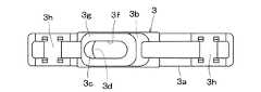
図3は取付部3の正面図、図4は平面図、図5は底面図、図6は側面図である。取付部3には、管体Pの表面の長手方向に沿って接触し、接触面が管体Pの表面にならって円弧状とされた長片状の接触部3aが形成されている。接触部3aの両端は稍々上方に持ち上げられ、接触部3a全体として僅かに反り上っている。接触部3aの中央部分には台形部3bが設けられ、台形部3b内には送受信部4とほぼ同等の大きさの貫通孔3cが形成され、貫通孔3c内に送受信部4が挿入されるようになっている。 3 is a front view of the
貫通孔3cの下部には、接触部3aに面して略矩形状の下開口部3dが形成され、下開口部3dの周囲には低段の凹部3eが設けられている。また、貫通孔3cの上部には上開口部3fが設けられ、上開口部3fを囲むように内方向に張り出す周縁部3gが形成されている。更に、接触部3aの長手方向の両端部には締付バンド2を配置するための溝部3hが設けられている。 A substantially rectangular
図7は送受信部4を上方から見た斜視図、図8は下方から見た斜視図である。送受信部4の下部の略矩形板状の接面部4aは、取付部3の下開口部3dを覆う大きさとされ、下開口部3dの周囲の凹部3eに入り込む大きさと厚みを有している。そして、接面部4aは管体Pにならって断面が円弧状とされている。 FIG. 7 is a perspective view of the transmission /
送受信部4の接面部4aの中央部から上方に向けた斜め方向に、取付部3の貫通孔3cに挿入される素子固定部4bが形成され、素子固定部4bの内部には装着孔4cが設けられ、この装着孔4cは接面部4aに開口されている。また、素子固定部4bの中間部の外側には、短手方向に向けて力伝達体としての軸部4dが設けられ、この軸部4dの両端部は上開口部3fの周囲の周縁部3gの下面に接するようにされている。そして、素子固定部4bの装着孔4c内には、接面部4aから上方に向けて、図9に示す合成樹脂材から成る柱状体の超音波伝達体4eが装着されている。 An
この超音波伝達体4eは素子固定部4bの装着孔4cの形状と合致し、装着孔4c内に嵌め込まれ、接着剤により固定されている。嵌め込んだ状態の超音波伝達体4eの端面である下面4fは、管体Pの表面にならって円弧状とされ、接面部4aと面一とされて接面部4aの一部とされている。また、超音波伝達体4eの上面4gには、ピエゾ素子のような圧電素子で、超音波ビームを送受信する超音波送受信素子4hが貼り付けられている。 The
超音波伝達体4eの上面4gは、例えば素子固定部4bの中心線と直交されていて、送受信素子4hを貼り付けた上面4gと、超音波ビームBを管体Pに対し斜め方向に入射させる下面4fとは平行ではなく、所定の角度を有する非平行とされている。 The
そして、超音波伝達体4eの下面4fの中心は、素子固定部4bの軸部4dの真下に位置しており、軸部4dに対する周縁部3gからの下方への応力は、下面4fの中心に向けて作用するようにされている。 The center of the
送受信素子4hにはリード線4iが接続されており、リード線4iは素子固定部4b内を経て、上部の孔部4jから外部に引き出され、図示しない演算制御部に接続されている。更に、超音波伝達体4eの下面4fを含む接面部4aには、管体Pとの接面状態を良好とするために、必要に応じて、柔軟性を有し、超音波ビームBに関し音響インピーダンスが合成樹脂材と合致する軟弾性部材として、例えばシリコンシート4kが貼り付けられている。 A
取付部3に送受信部4を組み込むには、超音波伝達体4eの上面4gにリード線4iを接続した送受信素子4hを貼り付けておく。この超音波伝達体4eを素子固定部4bの装着孔4c内に装着して固定した送受信部4を、接触部3aの下開口部3dから貫通孔3c内に挿入する。この状態で、送受信部4の上部は図1に示すように、台形部3bの上開口部3fから上方に突出される。 In order to incorporate the transmission /
送受信部4の取付部3の貫通孔3cへの挿入に伴って、送受信部4の軸部4dが取付部3の周縁部3gの下面に接触するので、それ以上に送受信部4を貫通孔3c内に挿入することはできない。この状態において、超音波伝達体4eの下面4fを含む送受信部4の接面部4aは、図10に示すように、取付部3の接触部3aよりも、稍々管体P側に突出するような位置関係とされている。 As the
使用に際しては、管体Pの両側に一対の送受信ユニット1を対称的に当接し、管体Pとシリコンシート4kと間に超音波ビームの伝達を良好とするためにグリスを塗布し、締付バンド2を用いて送受信ユニット1の両側を管体Pに対し強く固定する。本実施例の送受信ユニット1は、使用する管体Pの外径に適合するように製作されているので、管体Pに固定した一対の送受信ユニット1の送受信部4同士は管体Pを介して斜め方向の対向位置に配置される。 In use, a pair of transmission /
取付部3の接触部3aの両端は上方に稍々持ち上がっているので、接触部3aを管体Pに当接すると、接触部3aの両端は管体Pの表面から僅かに浮き上がる。ここで、締付バンド2により接触部3aの両端を締め付けて、取付部3を管体Pに固定する。これにより、接触部3aの両端は管体Pに密着し、取付部3の中央付近は管体Pに向けて強く押圧され、取付部3の周縁部3gから送受信部4の軸部4dに対し管体P側への強い押圧力が作用する。超音波伝達体4eの下面4fを含む送受信部4の接面部4aは、取付部3の接触部3aよりも管体P側に稍々突出しているので、取付部3と管体P間で強く押圧される。 Since both ends of the
また、取付部3、送受信部4の素材が持つ弾性により、取付部3、送受信部4が部分的に変形して押込力を吸収し、接面部4aは取付部3内に弾性的に押し込まれながら管体Pの表面に強く密着する。特に、軸部4dの下方に位置する超音波伝達体4eの下面4fには、強い押圧力が作用することになる。 Further, due to the elasticity of the material of the
下面4fの管体Pの表面に対するこのような強い押圧による密着によって、送受信素子4h同士間の管体Pを介する超音波ビームの送受信が良好になされ、測定精度が向上する。 Due to such close contact of the
また、シリコンシート4kを使用すれば、管体Pの表面と、仮に送受信部4の接面部4aとの間に部分的に隙間があっても、締付バンド2による締め付けによって、シリコンシート4kの肉厚が部分的に変化して、或る程度、これらの間隙を埋めることができるので、超音波ビームの伝達は更に良好となる。 Further, if the
演算制御部からのリード線4iを経由した指令により、一方の送受信ユニット1の送受信素子4hから発信された超音波ビームBは、超音波伝達体4eの上面4gから超音波伝達体4e内を直進して下面4fに至り、シリコンシート4kを経て、図2の点線で示すように、管体Pの壁面から流体内に入射する。超音波ビームBは更に管体P内の流体中を斜め方向に伝播し、管体Pの反対側の壁面から出射し、他方の送受信ユニット1のシリコンシート4k、超音波伝達体4eを経て送受信素子4hに到達する。 The ultrasonic beam B transmitted from the transmission /
管体P中の流体の流量を測定するには、2個の送受信部4の送受信素子4hから交互に超音波ビームを送受信する。流体の流れに沿って伝播する超音波ビームと、流れに逆行する超音波ビームとの到達時間差を制御演算部で測定し、流体の流速を求める。更に、制御演算部では管体Pの断面積を乗じて流量を演算する。この流速、流量の算出方法は超音波流量計の時間差方式として公知なので、説明は省略する。 In order to measure the flow rate of the fluid in the tubular body P, ultrasonic beams are transmitted and received alternately from the transmitting and receiving
なお、明細書の説明において、上下方向、左右方向とは実施例の図面に対しての説明であり、実際の部材はこれらの用語によって制限されるものではではない。 In the description of the specification, the vertical direction and the horizontal direction are descriptions with respect to the drawings of the embodiments, and actual members are not limited by these terms.
1 送受信ユニット
2 締付バンド
3 取付部
3a 接触部
3b 台形部
3c 貫通孔
3d 下開口部
3f 上開口部
4 送受信部
4a 接面部
4b 素子固定部
4c 装着孔
4d 軸部
4e 超音波伝達体
4f 下面
4g 上面
4h 超音波送受信素子
4i リード線
4k シリコンシート
B 超音波ビーム
P 管体DESCRIPTION OF
Claims (5)
Translated fromJapanese前記送受信ユニットは、前記管体の表面に接触して取り付ける取付部と、該取付部内に挿入し該取付部に内設する送受信部とから成り、
前記取付部は、前記管体の表面への接触部と、前記送受信部を受け入れる貫通孔と、前記管体に固定する固定手段とを備え、
前記送受信部は、前記管体に接面する板体状の接面部と、前記取付部の一部に接する力伝達部と、前記送受信素子を取り付けると共に前記貫通孔に挿入して固定し、端面が前記接面部に含まれ前記管体に接面する素子固定部とを備え、
前記固定手段により前記管体に前記取付部を固定すると、この固定力は前記力伝達部を介して前記送受信部に伝達され、前記接面部を前記管体に強く押圧することを特徴とする超音波式流量測定装置。A pair of transmission / reception units each including an ultrasonic transmission / reception element are arranged so as to sandwich a pipe body through which a fluid flows, and the pipe body is slanted between the transmission / reception elements at different positions along the pipe body of the transmission / reception unit. An ultrasonic flow measuring device that measures the flow rate of the fluid by alternately transmitting and receiving ultrasonic beams propagating in a direction,
The transmission / reception unit comprises an attachment portion that is attached in contact with the surface of the tubular body, and a transmission / reception portion that is inserted into the attachment portion and provided in the attachment portion.
The attachment portion includes a contact portion to the surface of the tubular body, a through-hole that receives the transmitting / receiving portion, and a fixing means that fixes the tubular body,
The transmission / reception unit includes a plate-shaped contact surface that contacts the tubular body, a force transmission unit that contacts a part of the mounting portion, and the transmission / reception element, and is inserted into the through hole and fixed, Including an element fixing portion included in the contact surface portion and in contact with the tubular body,
When the fixing portion is fixed to the tubular body by the fixing means, the fixing force is transmitted to the transmitting / receiving portion via the force transmitting portion, and the contact surface portion is strongly pressed against the tubular body. Sonic flow measuring device.
Priority Applications (6)
| Application Number | Priority Date | Filing Date | Title |
|---|---|---|---|
| JP2018201807AJP6454816B1 (en) | 2018-10-26 | 2018-10-26 | Ultrasonic flow measuring device |
| EP19197384.1AEP3644021B1 (en) | 2018-10-26 | 2019-09-13 | Ultrasonic flow measuring apparatus |
| US16/585,765US11181405B2 (en) | 2018-10-26 | 2019-09-27 | Clamp-type ultrasonic flow measuring apparatus with a mounter for press tight fit of a transmission/reception unit to the measuring pipe |
| CN201911014185.0ACN111103021B (en) | 2018-10-26 | 2019-10-23 | Ultrasonic flow measuring device |
| KR1020190133885AKR102230715B1 (en) | 2018-10-26 | 2019-10-25 | Ultrasonic flow measuring apparatus |
| TW108138669ATWI724589B (en) | 2018-10-26 | 2019-10-25 | Ultrasonic flow measuring apparatus |
Applications Claiming Priority (1)
| Application Number | Priority Date | Filing Date | Title |
|---|---|---|---|
| JP2018201807AJP6454816B1 (en) | 2018-10-26 | 2018-10-26 | Ultrasonic flow measuring device |
Publications (2)
| Publication Number | Publication Date |
|---|---|
| JP6454816B1true JP6454816B1 (en) | 2019-01-16 |
| JP2020067420A JP2020067420A (en) | 2020-04-30 |
Family
ID=65020391
Family Applications (1)
| Application Number | Title | Priority Date | Filing Date |
|---|---|---|---|
| JP2018201807AActiveJP6454816B1 (en) | 2018-10-26 | 2018-10-26 | Ultrasonic flow measuring device |
Country Status (6)
| Country | Link |
|---|---|
| US (1) | US11181405B2 (en) |
| EP (1) | EP3644021B1 (en) |
| JP (1) | JP6454816B1 (en) |
| KR (1) | KR102230715B1 (en) |
| CN (1) | CN111103021B (en) |
| TW (1) | TWI724589B (en) |
Cited By (1)
| Publication number | Priority date | Publication date | Assignee | Title |
|---|---|---|---|---|
| US11340101B2 (en) | 2019-04-24 | 2022-05-24 | Ryusok Co., Ltd. | Clamp-on ultrasonic flow measuring device for accurately positioning on an existing flow tube of a specific shape |
Families Citing this family (4)
| Publication number | Priority date | Publication date | Assignee | Title |
|---|---|---|---|---|
| JP6454816B1 (en)* | 2018-10-26 | 2019-01-16 | 株式会社琉Sok | Ultrasonic flow measuring device |
| USD1004412S1 (en)* | 2019-08-16 | 2023-11-14 | Deka Products Limited Partnership | Slide clamp assembly |
| WO2023094034A1 (en)* | 2021-11-28 | 2023-06-01 | Nvention Ltd | Flow sensing device and method |
| KR102675180B1 (en)* | 2023-10-18 | 2024-06-18 | 대한민국 | Electronic sounding device for fluid level measurement on ships |
Citations (6)
| Publication number | Priority date | Publication date | Assignee | Title |
|---|---|---|---|---|
| JPH10213467A (en)* | 1997-01-31 | 1998-08-11 | Tokimec Inc | Supersonic flowmeter for low temperature or high temperature |
| JP2003065818A (en)* | 2001-06-13 | 2003-03-05 | Fuji Electric Co Ltd | Ultrasonic flow measurement device |
| JP3841599B2 (en)* | 1999-10-14 | 2006-11-01 | 株式会社カイジョーソニック | Ultrasonic liquid flow detection sensor |
| US7146864B2 (en)* | 2003-03-04 | 2006-12-12 | Cidra Corporation | Apparatus having a multi-band sensor assembly for measuring a parameter of a fluid flow flowing within a pipe |
| JP2013174567A (en)* | 2012-02-27 | 2013-09-05 | Atsuden:Kk | Ultrasonic transceiver and clamp-on type ultrasonic flowmeter using ultrasonic transceiver |
| US10107786B2 (en)* | 2014-02-04 | 2018-10-23 | General Electric Company | Ultrasonic flow meter clamp |
Family Cites Families (25)
| Publication number | Priority date | Publication date | Assignee | Title |
|---|---|---|---|---|
| US4069433A (en)* | 1976-06-03 | 1978-01-17 | Westinghouse Electric Corporation | Modular transducer assembly |
| US4297607A (en)* | 1980-04-25 | 1981-10-27 | Panametrics, Inc. | Sealed, matched piezoelectric transducer |
| US5131278A (en)* | 1989-06-13 | 1992-07-21 | Joseph Baumoel | Mounting structure for transducers with sonic-energy absorbing means |
| JP2515943Y2 (en)* | 1990-02-02 | 1996-11-06 | 太陽鉄工株式会社 | Sensor mounting band |
| JPH10221137A (en) | 1997-02-10 | 1998-08-21 | Tokimec Inc | Jig for fitting probe of cryogenic ultrasonic flowmeter |
| US6397683B1 (en)* | 1998-07-22 | 2002-06-04 | Flowtec Ag | Clamp-on ultrasonic flowmeter |
| CN1101928C (en)* | 1998-07-22 | 2003-02-19 | 安德雷斯和霍瑟·弗罗泰克有限公司 | Holding ultrasound wave flowmeter |
| DE102005051336B4 (en)* | 2005-10-25 | 2014-12-31 | Krohne Ag | Method for attaching a clamp-on flowmeter to a measuring tube through which a fluid can flow |
| DE102005052550B3 (en)* | 2005-11-02 | 2007-02-08 | Krohne Ag | Clamp-on ultrasound flow-through measuring device comprises a guiding frame fixed to a fixing unit so that it moves away from or toward a tube and pivots along a pivoting axis |
| KR101254649B1 (en)* | 2011-08-02 | 2013-04-23 | 한국표준과학연구원 | Installation zig for ultrasonic flow meter |
| KR20130026863A (en)* | 2011-09-06 | 2013-03-14 | 이남석 | Flow meter using ultrasonic-sensor |
| JP2015064209A (en)* | 2013-09-24 | 2015-04-09 | Smc株式会社 | Ultrasonic flow meter |
| US20150107371A1 (en)* | 2013-10-18 | 2015-04-23 | General Electric Company | Method and system for determining characteristics of an acoustic signal |
| GB201402884D0 (en)* | 2014-02-18 | 2014-04-02 | Pcme Ltd | Ultrasonic flow probe and method of monitoring fluid flow in a conduit |
| CN203929143U (en)* | 2014-06-10 | 2014-11-05 | 宁波水表股份有限公司 | A kind of fast clamp formula Ultrasonic water meter |
| DE102014115203B3 (en)* | 2014-10-20 | 2016-03-24 | Flexim Flexible Industriemesstechnik Gmbh | Method and arrangement for ultrasonic clamp-on flow measurement and circuit arrangement for controlling an ultrasonic clamp-on flow measurement |
| US10222247B2 (en)* | 2016-07-07 | 2019-03-05 | Joseph Baumoel | Multiphase ultrasonic flow meter |
| CN106643933A (en)* | 2016-10-21 | 2017-05-10 | 汇中仪表股份有限公司 | Installation method of portable ultrasonic flowmeter |
| JP6747994B2 (en)* | 2017-01-26 | 2020-08-26 | 株式会社キーエンス | Ultrasonic flow sensor and mounting method thereof |
| CN206804074U (en)* | 2017-06-15 | 2017-12-26 | 刘华丽 | A kind of ultrasonic transducer fastener for clamping ultrasonic flowmeter |
| CN107576362A (en)* | 2017-09-21 | 2018-01-12 | 镇江龙逸电子科技有限公司 | A kind of servicing unit of external-clamping type ultrasonic flowmeter |
| CN107907174A (en)* | 2017-12-15 | 2018-04-13 | 深圳市广域创新科技发展有限公司 | Clamping device for mounting ultrasonic flowmeter sensor |
| CN207798172U (en)* | 2018-01-31 | 2018-08-31 | 深圳市深科工程检测有限公司 | A kind of probe gripper of hand-held ultrasonic flowmeter |
| EP3803312A1 (en)* | 2018-06-08 | 2021-04-14 | Orbis Intelligent Systems, Inc. | Pipe sensors |
| JP6454816B1 (en)* | 2018-10-26 | 2019-01-16 | 株式会社琉Sok | Ultrasonic flow measuring device |
- 2018
- 2018-10-26JPJP2018201807Apatent/JP6454816B1/enactiveActive
- 2019
- 2019-09-13EPEP19197384.1Apatent/EP3644021B1/enactiveActive
- 2019-09-27USUS16/585,765patent/US11181405B2/enactiveActive
- 2019-10-23CNCN201911014185.0Apatent/CN111103021B/enactiveActive
- 2019-10-25TWTW108138669Apatent/TWI724589B/enactive
- 2019-10-25KRKR1020190133885Apatent/KR102230715B1/enactiveActive
Patent Citations (6)
| Publication number | Priority date | Publication date | Assignee | Title |
|---|---|---|---|---|
| JPH10213467A (en)* | 1997-01-31 | 1998-08-11 | Tokimec Inc | Supersonic flowmeter for low temperature or high temperature |
| JP3841599B2 (en)* | 1999-10-14 | 2006-11-01 | 株式会社カイジョーソニック | Ultrasonic liquid flow detection sensor |
| JP2003065818A (en)* | 2001-06-13 | 2003-03-05 | Fuji Electric Co Ltd | Ultrasonic flow measurement device |
| US7146864B2 (en)* | 2003-03-04 | 2006-12-12 | Cidra Corporation | Apparatus having a multi-band sensor assembly for measuring a parameter of a fluid flow flowing within a pipe |
| JP2013174567A (en)* | 2012-02-27 | 2013-09-05 | Atsuden:Kk | Ultrasonic transceiver and clamp-on type ultrasonic flowmeter using ultrasonic transceiver |
| US10107786B2 (en)* | 2014-02-04 | 2018-10-23 | General Electric Company | Ultrasonic flow meter clamp |
Cited By (1)
| Publication number | Priority date | Publication date | Assignee | Title |
|---|---|---|---|---|
| US11340101B2 (en) | 2019-04-24 | 2022-05-24 | Ryusok Co., Ltd. | Clamp-on ultrasonic flow measuring device for accurately positioning on an existing flow tube of a specific shape |
Also Published As
| Publication number | Publication date |
|---|---|
| KR20200047429A (en) | 2020-05-07 |
| CN111103021A (en) | 2020-05-05 |
| TW202024574A (en) | 2020-07-01 |
| KR102230715B1 (en) | 2021-03-23 |
| JP2020067420A (en) | 2020-04-30 |
| CN111103021B (en) | 2022-04-01 |
| US11181405B2 (en) | 2021-11-23 |
| EP3644021B1 (en) | 2023-02-22 |
| TWI724589B (en) | 2021-04-11 |
| EP3644021A1 (en) | 2020-04-29 |
| US20200132526A1 (en) | 2020-04-30 |
Similar Documents
| Publication | Publication Date | Title |
|---|---|---|
| JP6454816B1 (en) | Ultrasonic flow measuring device | |
| US6883386B2 (en) | Ultrasonic flow rate measurement instrument | |
| EP2918980B1 (en) | Ultrasonic flow meter | |
| JP2003050144A (en) | Ultrasonic flow measurement device | |
| JP5728657B2 (en) | Ultrasonic flow measurement unit | |
| US10451465B2 (en) | Gas meter | |
| JP5622383B2 (en) | Ultrasonic flow measuring device | |
| WO2016166933A1 (en) | Flow rate measurement device | |
| TW202040104A (en) | Ultrasonic flow amount measuring device | |
| JP2002236042A (en) | Flowmeter | |
| TW202426867A (en) | Clamp-on type ultrasonic flowmeter | |
| CN118243181A (en) | Clamp-on ultrasonic flow meter | |
| JP2003083786A (en) | Ultrasonic flow measurement device | |
| JPH11325992A (en) | Ultrasonic vibrator, support structure thereof, and ultrasonic flow rate measuring device using the same | |
| CN212364346U (en) | Ultrasonic flow detection device and jet flow sensing mechanism | |
| JPH0422454B2 (en) | ||
| JP7755892B1 (en) | Clamp-on ultrasonic transmitter/receiver | |
| JP7029599B2 (en) | Ultrasonic flow meter | |
| JP2024070541A (en) | Ultrasonic measurement device and fluid measurement method | |
| KR200489769Y1 (en) | Ultrasonic flow meter with enhanced adhesion to pipe | |
| JP2025020497A (en) | Ultrasonic sensors and ultrasonic flow meters | |
| US9618372B2 (en) | Transit time flow meter probe | |
| US20200191627A1 (en) | Measuring device for determining a fluid variable | |
| JP2024090371A (en) | Clamp-on ultrasonic flowmeter | |
| JP2006098070A (en) | Ultrasonic flowmeter |
Legal Events
| Date | Code | Title | Description |
|---|---|---|---|
| A621 | Written request for application examination | Free format text:JAPANESE INTERMEDIATE CODE: A621 Effective date:20181026 | |
| A871 | Explanation of circumstances concerning accelerated examination | Free format text:JAPANESE INTERMEDIATE CODE: A871 Effective date:20181026 | |
| A975 | Report on accelerated examination | Free format text:JAPANESE INTERMEDIATE CODE: A971005 Effective date:20181101 | |
| A131 | Notification of reasons for refusal | Free format text:JAPANESE INTERMEDIATE CODE: A131 Effective date:20181113 | |
| A521 | Request for written amendment filed | Free format text:JAPANESE INTERMEDIATE CODE: A523 Effective date:20181119 | |
| TRDD | Decision of grant or rejection written | ||
| A01 | Written decision to grant a patent or to grant a registration (utility model) | Free format text:JAPANESE INTERMEDIATE CODE: A01 Effective date:20181204 | |
| A61 | First payment of annual fees (during grant procedure) | Free format text:JAPANESE INTERMEDIATE CODE: A61 Effective date:20181217 | |
| R150 | Certificate of patent or registration of utility model | Ref document number:6454816 Country of ref document:JP Free format text:JAPANESE INTERMEDIATE CODE: R150 | |
| R250 | Receipt of annual fees | Free format text:JAPANESE INTERMEDIATE CODE: R250 | |
| R250 | Receipt of annual fees | Free format text:JAPANESE INTERMEDIATE CODE: R250 | |
| R250 | Receipt of annual fees | Free format text:JAPANESE INTERMEDIATE CODE: R250 | |
| R250 | Receipt of annual fees | Free format text:JAPANESE INTERMEDIATE CODE: R250 |