JP6453658B2 - Electric tool - Google Patents
Electric toolDownload PDFInfo
- Publication number
- JP6453658B2 JP6453658B2JP2015009690AJP2015009690AJP6453658B2JP 6453658 B2JP6453658 B2JP 6453658B2JP 2015009690 AJP2015009690 AJP 2015009690AJP 2015009690 AJP2015009690 AJP 2015009690AJP 6453658 B2JP6453658 B2JP 6453658B2
- Authority
- JP
- Japan
- Prior art keywords
- metal sleeve
- housing
- resin base
- fan
- brush holder
- Prior art date
- Legal status (The legal status is an assumption and is not a legal conclusion. Google has not performed a legal analysis and makes no representation as to the accuracy of the status listed.)
- Active
Links
- 239000002184metalSubstances0.000claimsdescription98
- 239000011347resinSubstances0.000claimsdescription67
- 229920005989resinPolymers0.000claimsdescription67
- 238000009423ventilationMethods0.000claimsdescription5
- 230000000717retained effectEffects0.000claimsdescription2
- 230000000694effectsEffects0.000description15
- 230000007246mechanismEffects0.000description10
- 238000001816coolingMethods0.000description8
- 230000017525heat dissipationEffects0.000description7
- 230000008859changeEffects0.000description6
- 229910000831SteelInorganic materials0.000description5
- 230000002093peripheral effectEffects0.000description5
- 239000010959steelSubstances0.000description5
- OKTJSMMVPCPJKN-UHFFFAOYSA-NCarbonChemical compound[C]OKTJSMMVPCPJKN-UHFFFAOYSA-N0.000description4
- 229910052799carbonInorganic materials0.000description4
- 230000009467reductionEffects0.000description3
- 230000005540biological transmissionEffects0.000description2
- 210000000078clawAnatomy0.000description2
- 230000008878couplingEffects0.000description2
- 238000010168coupling processMethods0.000description2
- 238000005859coupling reactionMethods0.000description2
- 125000006850spacer groupChemical group0.000description2
- 230000004323axial lengthEffects0.000description1
- 239000000969carrierSubstances0.000description1
- 230000003247decreasing effectEffects0.000description1
- WABPQHHGFIMREM-UHFFFAOYSA-Nlead(0)Chemical compound[Pb]WABPQHHGFIMREM-UHFFFAOYSA-N0.000description1
- 238000005192partitionMethods0.000description1
- 230000000149penetrating effectEffects0.000description1
- 239000007787solidSubstances0.000description1
Images


Classifications
- H—ELECTRICITY
- H02—GENERATION; CONVERSION OR DISTRIBUTION OF ELECTRIC POWER
- H02K—DYNAMO-ELECTRIC MACHINES
- H02K9/00—Arrangements for cooling or ventilating
- H02K9/28—Cooling of commutators, slip-rings or brushes e.g. by ventilating
- B—PERFORMING OPERATIONS; TRANSPORTING
- B25—HAND TOOLS; PORTABLE POWER-DRIVEN TOOLS; MANIPULATORS
- B25F—COMBINATION OR MULTI-PURPOSE TOOLS NOT OTHERWISE PROVIDED FOR; DETAILS OR COMPONENTS OF PORTABLE POWER-DRIVEN TOOLS NOT PARTICULARLY RELATED TO THE OPERATIONS PERFORMED AND NOT OTHERWISE PROVIDED FOR
- B25F5/00—Details or components of portable power-driven tools not particularly related to the operations performed and not otherwise provided for
- B25F5/008—Cooling means
- B—PERFORMING OPERATIONS; TRANSPORTING
- B25—HAND TOOLS; PORTABLE POWER-DRIVEN TOOLS; MANIPULATORS
- B25F—COMBINATION OR MULTI-PURPOSE TOOLS NOT OTHERWISE PROVIDED FOR; DETAILS OR COMPONENTS OF PORTABLE POWER-DRIVEN TOOLS NOT PARTICULARLY RELATED TO THE OPERATIONS PERFORMED AND NOT OTHERWISE PROVIDED FOR
- B25F5/00—Details or components of portable power-driven tools not particularly related to the operations performed and not otherwise provided for
- B25F5/001—Gearings, speed selectors, clutches or the like specially adapted for rotary tools
- H—ELECTRICITY
- H02—GENERATION; CONVERSION OR DISTRIBUTION OF ELECTRIC POWER
- H02K—DYNAMO-ELECTRIC MACHINES
- H02K9/00—Arrangements for cooling or ventilating
- H02K9/02—Arrangements for cooling or ventilating by ambient air flowing through the machine
- H02K9/04—Arrangements for cooling or ventilating by ambient air flowing through the machine having means for generating a flow of cooling medium
- H02K9/06—Arrangements for cooling or ventilating by ambient air flowing through the machine having means for generating a flow of cooling medium with fans or impellers driven by the machine shaft
- H—ELECTRICITY
- H02—GENERATION; CONVERSION OR DISTRIBUTION OF ELECTRIC POWER
- H02K—DYNAMO-ELECTRIC MACHINES
- H02K7/00—Arrangements for handling mechanical energy structurally associated with dynamo-electric machines, e.g. structural association with mechanical driving motors or auxiliary dynamo-electric machines
- H02K7/14—Structural association with mechanical loads, e.g. with hand-held machine tools or fans
- H02K7/145—Hand-held machine tool
Landscapes
- Engineering & Computer Science (AREA)
- Power Engineering (AREA)
- Mechanical Engineering (AREA)
- Motor Or Generator Current Collectors (AREA)
- Motor Or Generator Frames (AREA)
- Motor Or Generator Cooling System (AREA)
- Dc Machiner (AREA)
- Connection Of Motors, Electrical Generators, Mechanical Devices, And The Like (AREA)
Description
Translated fromJapanese本発明は、駆動源として整流子モータを用いた震動ドライバドリル等の電動工具に関する。 The present invention relates to an electric tool such as a vibration driver drill using a commutator motor as a drive source.
震動ドライバドリルやインパクトドライバ等の電動工具においては、駆動源として整流子モータを用いたものが知られている。この場合、円盤状の樹脂ベースに、ブラシを保持する筒状の金属スリーブを半径方向に取り付けてなるブラシホルダを、ハウジング内で回転軸と直交状に保持させて、ブラシホルダを貫通する整流子にブラシを圧接させる構造が採用される。
このブラシは、整流子モータの駆動によって整流子と摺接することで発熱するため、金属スリーブも高温となる。回転子の回転軸には、モータ冷却用のファンが設けられるため、ファンによってハウジング内に生じる空気流でブラシホルダを冷却する対策が採られているが、金属スリーブは樹脂ベースに密着して取り付けられているため、取付面で効果的に冷却されず、金属スリーブが高温になると樹脂ベースが溶融するおそれがある。そこで、特許文献1には、金属スリーブの下面側に仕切板を設けて金属スリーブの下側に通風空隙を設けたり、金属スリーブに切欠部を形成したりして冷却風との接触を図るブラシホルダの発明が開示されている。Among power tools such as a vibration driver drill and an impact driver, those using a commutator motor as a drive source are known. In this case, a brush holder formed by attaching a cylindrical metal sleeve for holding a brush to a disc-shaped resin base in the radial direction is held perpendicular to the rotation axis in the housing, and the commutator passes through the brush holder. A structure is adopted in which the brush is pressed against.
Since this brush generates heat by being in sliding contact with the commutator by driving the commutator motor, the metal sleeve is also heated. Since the motor's fan is provided on the rotor's rotating shaft, measures are taken to cool the brush holder with the airflow generated in the housing by the fan, but the metal sleeve is attached in close contact with the resin base. Therefore, the mounting surface is not effectively cooled, and the resin base may be melted when the metal sleeve reaches a high temperature. Therefore, Patent Document 1 discloses a brush that is provided with a partition plate on the lower surface side of the metal sleeve to provide a ventilation gap on the lower side of the metal sleeve, or to form a notch in the metal sleeve to make contact with the cooling air. The invention of the holder is disclosed.
しかし、樹脂ベースを挟んでファンと反対側に金属スリーブが位置する向きでブラシホルダが保持されると、冷却風の流れが樹脂ベースによって妨げられるため、冷却風が乱流を起こして金属スリーブ側に流れなかったり、金属スリーブを通過せずに直接整流子側へ流れたりして金属スリーブの下側に導かれず、効果的に冷却が行えない。 However, if the brush holder is held in such a direction that the metal sleeve is positioned on the opposite side of the fan across the resin base, the flow of cooling air is hindered by the resin base. Or flow directly to the commutator side without passing through the metal sleeve and is not guided to the lower side of the metal sleeve, and cooling cannot be effectively performed.
そこで、本発明は、金属スリーブを効果的に冷却できる電動工具を提供すること目的としたものである。 Then, this invention aims at providing the electric tool which can cool a metal sleeve effectively.
上記目的を達成するために、請求項1に記載の発明は、ハウジングと、ハウジング内に収容され、ファンを備える整流子モータと、ハウジング内に設けられ、ブラシを収容する金属スリーブと、その金属スリーブを片面側で保持する樹脂ベースとからなるブラシホルダと、を含み、樹脂ベースに、金属スリーブを前記片面側と反対側の面に露出させる開口部を設ける一方、ブラシホルダを、ファン側に樹脂ベースが位置する向きで配置して、ファンの回転により、金属スリーブ側でハウジングに設けた吸気口から吸い込んだ空気がブラシホルダ及び整流子モータの整流子を通過して、ファン側でハウジングに設けた排気口から排出されるようにしたことを特徴とするものである。
請求項2に記載の発明は、請求項1の構成において、樹脂ベースに、金属スリーブが保持される片面側から開口部に繋がる通気路を形成したことを特徴とするものである。
請求項3に記載の発明は、請求項2の構成において、金属スリーブに、通気路内に突出するフランジ部を設けたことを特徴とするものである。
請求項4に記載の発明は、請求項2又は3の構成において、樹脂ベースにおける金属スリーブが保持される片面側に、吸気口から吸い込まれた空気が通気路の入口近傍で衝突する乱流用リブを設けたことを特徴とするものである。
請求項5に記載の発明は、請求項1乃至4の何れかの構成において、金属スリーブの底面における少なくとも開口部への露出部分に、凹凸を形成したことを特徴とするものである。
上記目的を達成するために、請求項6に記載の発明は、ハウジングと、ハウジング内に設けられ、ファンを備えた整流子モータと、ハウジング内に設けられ、ブラシを収容する金属スリーブと、その金属スリーブを片面側で保持する樹脂ベースとからなるブラシホルダと、を備え、ブラシホルダを、ファン側に樹脂ベースが位置する向きで配置して、ファンの回転により、金属スリーブ側でハウジングに設けた吸気口から吸い込んだ空気がブラシホルダ及び整流子モータの整流子を通過して、ファン側でハウジングに設けた排気口から排出される電動工具であって、金属スリーブと樹脂ベースとの間に、吸気口から吸い込まれた空気が通過する通気路を形成したことを特徴とするものである。
上記目的を達成するために、請求項7に記載の発明は、ハウジングと、ハウジング内に設けられ、ファンを備えた整流子モータと、ハウジング内に設けられ、ブラシを収容する金属スリーブと、その金属スリーブを片面側で保持する樹脂ベースとからなるブラシホルダと、を備え、ブラシホルダを、ファン側に樹脂ベースが位置する向きで配置して、ファンの回転により、金属スリーブ側でハウジングに設けた吸気口から吸い込んだ空気がブラシホルダ及び整流子モータの整流子を通過して、ファン側でハウジングに設けた排気口から排出される電動工具であって、樹脂ベースに、吸気口から吸い込まれた空気を金属スリーブ側へ案内する整流部を一体に形成したことを特徴とするものである。To achieve the above object, an invention according to claim 1, a housing, is accommodated in thehousing, a commutator motor Rucomprising a fan, disposed within the housing, and a metal sleeve for accommodating the brush, its includes a brush holder made of a resin base for holding the metal sleeve in one side, and the resin base,while the openingRu provided for exposing the metal sleeve on the opposite side to the oneside, the brush holder, fan When the fan rotates, the air sucked from the air inlet provided in the housing on the metal sleeve side passes through the brush holder and the commutator of the commutator motor, It is characterizedby being discharged from an exhaust port provided in the housing .
According to asecond aspect of the invention, in the configuration of claim1, the resin base, and is characterized in that the metal sleeve to form a ventilation path leading to the opening from the one side to be retained.
According to athird aspect of the present invention, in the configuration of thesecond aspect , the metal sleeve is provided with a flange portion protruding into the air passage.
According to afourth aspect of the present invention, in the configuration of thesecond or third aspect , the turbulent flow rib in which the air sucked from the air inlet collides in the vicinity of the inlet of the air passage on one side of the resin base where the metal sleeve is held. Is provided.
According to afifth aspect of the present invention, in the structure according to any one of the first tofourth aspects, an unevenness is formed at least in an exposed portion of the bottom surface of the metal sleeve to the opening.
In order to achieve the above object, an invention according to
In order to achieve the above object, an invention according to
請求項1に記載の発明によれば、ブラシホルダの樹脂ベースに開口部を設けたことで、樹脂ベースにおける金属スリーブの保持面と反対側の面でも空気が金属スリーブと接触する。よって、金属スリーブの放熱効果が得られて効果的に冷却できる。
また、吸気口から吸い込まれた空気がブラシホルダを通過する際に開口部を介して金属スリーブに接触する。よって、金属スリーブとファンとの間に樹脂ベースがあっても金属スリーブを効果的に冷却することができる。
請求項2に記載の発明によれば、請求項1の効果に加えて、樹脂ベースに、開口部に繋がる通気路を形成したことで、金属スリーブの底面で空気流が生じて金属スリーブの冷却効果が高まる。
請求項3に記載の発明によれば、請求項2の効果に加えて、金属スリーブに、通気路内に突出するフランジ部を設けたことで、通気路内の空気流との接触面積が多くなって放熱効果が高まる。
請求項4に記載の発明によれば、請求項2又は3の効果に加えて、樹脂ベースに乱流用リブを設けたことで、乱流用リブに衝突した空気の勢いが弱められて通気路へ進入しやすくなる。
請求項5に記載の発明によれば、請求項1乃至4の何れかの効果に加えて、金属スリーブの底面に凹凸を形成したことで、金属スリーブの底面と空気流との接触面積が増大し、より高い放熱効果が得られる。
請求項6に記載の発明によれば、金属スリーブと樹脂ベースとの間に通気路を形成したことで、空気が通気路内を通過して金属スリーブの底面に接触するため、金属スリーブの冷却効果が得られる。
請求項7に記載の発明によれば、整流部によって導かれる空気により金属スリーブを効果的に冷却できると共に、整流部を簡単に形成することができる。
According to the first aspect of the present invention, since the opening is provided in the resin base of the brush holder, air contacts the metal sleeve even on the surface of the resin base opposite to the holding surface of the metal sleeve. Therefore, the heat dissipation effect of the metal sleeve can be obtained and cooling can be performed effectively.
Further , when the air sucked from the air inlet passes through the brush holder, it contacts the metal sleeve through the opening. Therefore, even if there is a resin base between the metal sleeve and the fan, the metal sleeve can be effectively cooled.
According to thesecond aspect of the present invention, in addition to the effect of thefirst aspect , since the air passage connected to the opening is formed in the resin base, an air flow is generated on the bottom surface of the metal sleeve, thereby cooling the metal sleeve. Increases effectiveness.
According to thethird aspect of the present invention, in addition to the effect of thesecond aspect , the metal sleeve is provided with the flange portion protruding into the air passage so that the contact area with the air flow in the air passage is large. This increases the heat dissipation effect.
According to thefourth aspect of the present invention, in addition to the effect of thesecond or third aspect , by providing the turbulent flow rib on the resin base, the momentum of the air colliding with the turbulent flow rib is weakened and the air passage is made. It becomes easy to enter.
According to thefifth aspect of the present invention, in addition to the effect of any one of the first tofourth aspects, the contact area between the bottom surface of the metal sleeve and the air flow is increased by forming irregularities on the bottom surface of the metal sleeve. In addition, a higher heat dissipation effect can be obtained.
According to thesixth aspect of the present invention, since the air passage is formed between the metal sleeve and the resin base, air passes through the air passage and contacts the bottom surface of the metal sleeve. An effect is obtained.
According to theseventh aspect of the invention, the metal sleeve can be effectively cooled by the air guided by the rectification unit, and the rectification unit can be easily formed.
以下、本発明の実施の形態を図面に基づいて説明する。
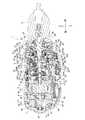
図1は、電動工具の一例を示す震動ドライバドリルの側面図、図2は背面図、図3はリヤカバーを取り外した状態の背面図、図4は一部縦断面図である。震動ドライバドリル1は、前後方向に延びる本体2の下側からハンドル3を突出させた側面視T字状で、本体2の前端には、先端でビットを把持可能なドリルチャック4が設けられる一方、ハンドル3の下端には、電源となるバッテリーパック5が装着されている。ここでのハウジングは、本体2の後半部分とハンドル3とが連設される本体ハウジング6の後部に、キャップ状のリヤカバー7を組み付けてなり、本体ハウジング6は、左右の半割ハウジング6a,6bを左右方向のネジ8,8・・によって組み付けて形成される。Hereinafter, embodiments of the present invention will be described with reference to the drawings.
1 is a side view of a vibration driver drill showing an example of an electric tool, FIG. 2 is a rear view, FIG. 3 is a rear view with a rear cover removed, and FIG. 4 is a partial longitudinal sectional view. The vibration driver drill 1 has a T-shape in a side view in which a handle 3 protrudes from the lower side of a
本体2内において、後部には、固定子10と回転子11とからなり、回転子11に回転軸12及び整流子13を備えた整流子モータ9が収容されている。整流子モータ9の前方には、本体ハウジング6から前方へ突出するスピンドル15を備えたギヤアッセンブリ14が組み付けられて、回転軸12の回転を減速してスピンドル15に伝達可能となっている。ドリルチャック4はスピンドル15の前端に取り付けられている。本体2の下方でハンドル3の上部には、図示しないスイッチが収容されて、トリガ16を前方へ突出させている。スイッチの上方にはモータの正逆切替ボタン17が設けられて、その前方には、ドリルチャック4の前方を照射するLED18が斜め上向きに収容されている。ハンドル3の下端には、バッテリーパック5の装着部19が形成され、装着部19には、バッテリーパック5が電気的に接続される端子台の他、端子台やスイッチ、整流子モータ9と配線される図示しないコントローラが収容されている。20は装着部19の左側面にネジ止めされた吊り下げ用のフックである。 In the
本体2内で整流子モータ9の前方には、回転軸12の前端に設けたピニオン21を軸受23を介して支持するモータブラケット22が組み付けられている。ギヤアッセンブリ14は、モータブラケット22に連結される筒状の第1ギヤケース24と、その第1ギヤケース24の前方に組み付けられ、大径部26と小径部27との二段筒形状を有する第2ギヤケース25とから形成されている。
ギヤアッセンブリ14の内部には、インターナルギヤ31A〜31C内で公転する複数の遊星ギヤ30A〜30Cを支持するキャリア29A〜29Cを、軸方向に三段配置してなる遊星歯車減速機構28が収容されて、回転軸12のピニオン21が一段目の遊星ギヤ30Aに噛合している。このうち二段目のインターナルギヤ31Bは、回転可能且つ軸方向へ前後移動可能となっている。このインターナルギヤ31Bは、前進位置で大径部26内に保持された結合リング32と噛合可能となっている。A
The
一方、インターナルギヤ31Bの後半部には、前後移動可能な速度切替リング33が外装されて、前後方向で一体に結合されている。この速度切替リング33から上方へ突設された連結片34が、本体ハウジング2に前後へスライド可能に設けられた速度切替レバー35に、前後のコイルバネ36,36を介して連結されている。
この速度切替レバー35を後方へスライドさせると、連結片34を介して速度切替リング33が後退し、これと一体のインターナルギヤ31Bが、二段目の遊星ギヤ30Bとの噛合を保ったまま一段目のキャリア29Aの外周に設けた歯にも噛合する。よって、二段目の減速がキャンセルされる高速モードとなる。逆に速度切替レバー35を前方へスライドさせると、速度切替リング33と共にインターナルギヤ31Bもキャリア29Aから離れて前進し、二段目の遊星ギヤ30Bとの噛合を保ったまま結合リング32に噛合して回転規制される。よって、二段目の減速が機能する低速モードとなる。On the other hand, a speed switching ring 33 that can move back and forth is externally attached to the rear half of the
When the
そして、ここでは第2ギヤケース25の小径部27の内側に、スピンドル15に軸方向への震動を付与する震動機構37が設けられ、小径部27の外側に、スピンドル15への所定の負荷でスピンドル15へのトルク伝達を遮断するクラッチ機構38が設けられて、後述する切替操作により、スピンドル15が回転しながら震動する震動ドリルモード、スピンドル15が回転のみ行うドリルモード、所定の負荷でスピンドル15へのトルク伝達を遮断するクラッチモード(ドライバモード)がそれぞれ選択可能となっている。以下、各機構について説明する。 In this case, a
まず、震動機構37において、スピンドル15は、小径部27内で前後の軸受39,40によって軸支されると共に、その後端が三段目のキャリア29Cと一体のロックカム41にスプライン結合されて、軸方向へ前後移動可能となっている。
但し、スピンドル15は、その前方寄りに形成されたフランジ42と軸受39との間で外装されたコイルバネ43によって、常態では軸受39の後方位置で外装された止め輪44が軸受39に当接する前進位置に付勢されている。45は、小径部27の内周に前方から嵌入されて軸受39を位置決めする位置決めリング、46は、小径部27の前端にネジ止めされて位置決めリング45を抜け止めする円盤状の止め板である。First, in the
However, the spindle 15 is forwardly moved so that a retaining ring 44 that is externally mounted at a rear position of the bearing 39 abuts against the bearing 39 by a
また、スピンドル15における軸受39,40間には、前方からリング状の第1カム47、第2カム48が夫々同軸で外装されている。第1カム47は、後面に第1カム歯を有してスピンドル15に固着されている。第2カム48は、前面に第2カム歯を形成してスピンドル15に遊挿されて、後部外周には、噛み合い突起49が突設されている。
さらに、第2カム48の前方で軸受39との間には、リング状のスペーサ50が設けられて、第2カム48の後方には、複数のスチールボール51を介してワッシャ52が保持されている。よって、第2カム48は、スペーサ50とワッシャ52との間で軸方向の移動を規制されることになる。Further, between the bearings 39 and 40 in the spindle 15, a ring-shaped
Further, a ring-shaped spacer 50 is provided in front of the second cam 48 and between the bearings 39, and a washer 52 is held behind the second cam 48 via a plurality of
一方、小径部27には、一対の震動切替レバー53,53が点対称位置でスライド可能に収容されて、後方に設けたコイルバネ54,54によって前方へ付勢されている。この震動切替レバー53の後端内面側には、内側突起55が突設されて小径部27の内周側に突出し、前進位置で第2カム48の噛み合い突起49に係合可能となっている。また、震動切替レバー53の前端外面側には外側突起56が突設されて、小径部27の外周側に突出している。 On the other hand, in the
また、小径部27には、本体ハウジング6の前端と略同径の操作リング58と、操作リング58より小径でその前方に位置するカムリング59と、操作リング58とカムリング59とを連結する軸方向の連結板60とからなるモード切替リング57が回転可能に外装されている。このモード切替リング57のカムリング59の後端縁に、震動切替レバー53の外側突起56が当接することで、震動切替レバー53の前進を規制している。この状態で震動切替レバー53は後退位置にあって、内側突起55を第2カム48の噛み合い突起49から離間させるが、カムリング59には、点対称位置に図示しないカム凹部が凹設されており、外側突起56の前方にカム凹部が位置するモード切替リング57の回転位置では、震動切替レバー53が前進して内側突起55を第2カム48の噛み合い突起49に係合させる。 The small-
次に、クラッチ機構38について説明する。
まず、モード切替リング57の前方で小径部27には、内周に雌ネジ部を形成したクラッチリング61が回転可能に外装されている。クラッチリング61の内側には、外周に形成した雄ネジ部をモード切替リング57の連結板60の間から突出させたスプリングホルダ62が、クラッチリング61に螺合した状態で外装されて、回転規制された状態で軸方向に前後移動可能となっている。また、スプリングホルダ62の後方で小径部27には、コイルバネ63が外装されて、コイルバネ63の前端がスプリングホルダ62に保持される一方、コイルバネ63の後端は、大径部26と小径部27との間の閉塞部64の前面に設けたフラットワッシャ65に当接している。
このフラットワッシャ65は、モード切替リング57と一体に回転可能且つ別体で軸方向へ移動可能となっており、モード切替リング57の回転操作により、内周に設けた図示しない内突起が小径部27に設けた突条と軸方向で重なって前方への移動が規制される位置と、内突起が突条と重ならずに前方への移動が許容される位置とに変更可能となっている。Next, the
First, in front of the
The
また、フラットワッシャ65の後方で閉塞部64には、前後2つのスチールボール66,66が周方向へ等間隔に保持されて、回転可能に設けられた三段目のインターナルギヤ31Cの前面に当接し、インターナルギヤ31Cの前面に突設された図示しないクラッチカムと周方向で係合可能となっている。このスチールボール66及びフラットワッシャ65を介してコイルバネ63の付勢力がインターナルギヤ31Cへ伝わることで、インターナルギヤ31Cは回転規制される。クラッチリング61を回転操作してスプリングホルダ62を軸方向にネジ送りしてコイルバネ63の軸長を変化させることで、インターナルギヤ31Cへの付勢力が変更可能となる。 Further, the front and rear two
ここで、まずフラットワッシャ65の内突起が小径部27の突条と重ならない位相となるモード切替リング57の第一の回転位置では、カムリング59のカム凹部は震動切替レバー53の前方に位置しないため、震動切替レバー53は後退位置にあって内側突起55と第2カム48とは結合されない。よって、第2カム48は回転フリー状態、フラットワッシャ65は前方へ移動可能な状態で、クラッチリング61の回転操作によってフラットワッシャ65への押圧力が変更可能なクラッチモードとなる。 Here, first, the cam recess of the
このクラッチモードでトリガ16を押し込み操作して整流子モータ9を駆動させると、回転軸12が回転し、遊星歯車減速機構28を介してスピンドル15が回転し、ドリルチャック4に装着したドライバビットでネジ締め等を行うことができる。ネジ締めが進んでスピンドル15への負荷が、インターナルギヤ31Cを固定するコイルバネ63の押圧力を超えると、インターナルギヤ31Cのクラッチカムがスチールボール66及びフラットワッシャ65を前方へ押し出してインターナルギヤ31Cを空転させ、ネジ締めを終了させる(クラッチ作動)。なお、ドライバビットのネジへの押し付けによってスピンドル15が後退し、第1カム47が第2カム48と噛合することになるが、第2カム48は回転フリー状態となっているため、第1カム47と共に回転し、スピンドル15に震動は発生しない。 When the commutator motor 9 is driven by pushing the
次に、クラッチモードからモード切替リング57を所定角度左回転させた第二の回転位置では、カムリング59のカム凹部は未だ震動切替レバー53の前方になく、震動切替レバー53は後退位置のままであるが、フラットワッシャ65は回転して内突起を小径部27の突条の後方に位置させる。よって、コイルバネ63の押圧力の大小にかかわらずフラットワッシャ65の前方への移動が突条によって常に規制されるドリルモードとなる。
このドリルモードでスピンドル15を回転させると、スピンドル15への負荷にかかわらず、スチールボール66がインターナルギヤ31Cのクラッチカムを乗り越えることがないため、インターナルギヤ31Cの固定状態は変わらず、スピンドル15の回転は継続する。なお、このときも第2カム48の回転フリー状態は変わらないため、スピンドル15に震動は発生しない。Next, in the second rotational position in which the
When the spindle 15 is rotated in this drill mode, the
そして、ドリルモードからモード切替リング57をさらに所定角度左回転させた第三の回転位置では、カムリング59のカム凹部は震動切替レバー53の前方に位置し、震動切替レバー53の前進を許容して内側突起55を第2カム48と結合させる。一方、フラットワッシャ65の内突起と小径部27の突条との軸方向での干渉は変わらない。よって、スピンドル15の後退位置で第1カム47と第2カム48とが噛合する震動モードとなる。
この震動モードでスピンドル15を回転させた場合、ドリルビット等を被加工材に押し当ててスピンドル15が後退すると、スピンドル15と一体回転する第1カム47が、震動切替レバー53で固定される第2カム48と噛合するため、スピンドル15に震動が発生する。なお、突条によるフラットワッシャ65の固定状態は変わらないため、スピンドル15への負荷にかかわらずスピンドル15の回転は継続することになる。Then, in the third rotation position in which the
When the spindle 15 is rotated in this vibration mode, when the spindle 15 moves backward by pressing a drill bit or the like against the workpiece, the
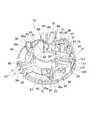
そして、本体2の後部において、整流子モータ9の回転軸12の後端は、リヤカバー7に保持された軸受67で支持される。回転軸12における固定子10の後方には、遠心ファン68が設けられ、遠心ファン68の内側で回転子11の後端面には、内側ファン69が設けられて、整流子13の外周側には、ブラシホルダ70が設けられている。リヤカバー7の背面には、図2に示すように、複数の後吸気口72,72・・の群からなる吸込部71A,71Bが、上下に分かれて設けられており、本体ハウジング6の左右の側面における遠心ファン68の外側には、複数の排気口73,73・・が設けられ、その前方には、複数の前吸気口74,74・・が設けられている(図1)。 The rear end of the
左右の半割ハウジング6a,6bには、図3,5に示すように、リヤカバー7を後方から左右のネジ76,76によって固定するためのネジボス75が、回転軸12寄りの内側位置でそれぞれ後向きに形成されており、ネジボス75の前側には、ブラシホルダ70の樹脂ベース78を保持する保持溝77が形成されている。
ブラシホルダ70は、図3,5及び図6〜8に示すように、円盤状の樹脂ベース78の後面に、カーボンブラシ80を保持する一対の角筒状の金属スリーブ79,79を、背面視でV字状となるように上半分側でそれぞれ半径方向へ左右対称に設けてなる。As shown in FIGS. 3 and 5, the left and
As shown in FIGS. 3, 5 and FIGS. 6 to 8, the
樹脂ベース78は、図9,10にも示すように、中心の貫通孔81に、後方へ突出する筒状の内リブ82を有し、外周に薄肉部83が形成される一方、内リブ82の周囲には厚肉部84が形成されている。薄肉部83の左右両側には、位置決め用の切欠き85,85が形成され、厚肉部84の左右両側には、中心側へ突出するネジボス75,75の嵌合部86,86が形成されている。薄肉部83の上側には、面取部87が形成されている。 As shown in FIGS. 9 and 10, the
また、樹脂ベース78の内リブ82において、金属スリーブ79,79の載置部P,Pの内側には、一対の開口88,88が設けられている。左右の開口88,88の間で内リブ82の上側部分には、左右を仕切る半径方向の上リブ89が連設され、上リブ89の上端で樹脂ベース78の外周には、円弧状の外リブ90が連設されている。この外リブ90は、内リブ82よりも突出高さが低くなっており、上リブ89は、内リブ82から外リブ90に向かって徐々に低くなるように後面が傾斜している。
上リブ89には、金属スリーブ79,79の左右の載置部P,Pに向けて傾斜する傾斜リブ91,91が左右対称に連設され、傾斜リブ91,91の外側には、カーボンブラシ80を付勢するトーションバネ92を固定する取付ボス93が突設されている。Further, in the
The
一方、内リブ82の下側中央には、内リブ82の下面から半径方向に延びる側面視L字状の下リブ94が突設され、下リブ94の下端左右には、下リブ94と平行な小リブ95,95が、下リブ94から間隔をおいて突設されている。また、左右の嵌合部86,86の下側には、内リブ82の外側で内リブ82に沿って湾曲する整流部としてのガイドリブ96,96が突設されている。金属スリーブ79に接続されるリード線97は、このガイドリブ96と内リブ82との間で内リブ82に沿って下方へ配線され、下リブ94の両側で小リブ95,95との間を通して引き出される。
さらに、嵌合部86,86の下側でガイドリブ96,96の外側には、上方へ行くに従って内リブ82に近づく方向へ傾斜する整流部としての整流用リブ98,98が立設され、嵌合部86,86の上側で金属スリーブ79の載置部Pの外側には、周方向に沿った乱流用リブ99,99が立設されている。各整流用リブ98の上端は、それぞれ上側の載置部Pに向けて切り欠いた傾斜面98aとなっており、各ガイドリブ96の上端における整流用リブ98側の面も、傾斜面98aと略平行に切り欠いた傾斜面96aとなっている。On the other hand, an L-shaped
Further, on the outer side of the
そして、載置部Pは、内リブ82の接線方向と平行な一対の凹溝100,100を、半径方向に所定間隔をおいて形成すると共に、各凹溝100の長手方向の中央に、樹脂ベース78を貫通する開口部101を半径方向にそれぞれ形成してなる。
ここにセットされる金属スリーブ79は、底面部分を形成するホルダベース102と、ホルダベース102越しに樹脂ベース78にカシメられてスリーブの両側面及び上面部分を形成する上筒103とからなる。ホルダベース102は、図11,12に示すように、細長矩形状の本体部104の長手側辺に、本体部104よりも長手寸法が短い細長矩形状のフランジ部105,105を連設した金属製のプレートで、本体部104の裏面には、V字状の切込み106,106・・が長手方向に所定間隔をおいて複数形成されることで凹凸形状となっている。本体部104の左右でフランジ部105,105との境目には、本体部104に沿った長円状の透孔107,107が、間隔をおいて2つずつ直線上に形成されている。また、各フランジ部105における各透孔107の外側には、裏側へ突出する短手方向の突条が形成されて、表面に、本体部104の延長面上で透孔107と連通する左右方向の溝108を形成している。ホルダベース102の短手方向の幅は、載置部Pの凹溝100の長さよりも小さくなっている。The mounting portion P forms a pair of
The
上筒103は、左右の側壁109,109と、側壁109,109の上端間を繋ぐ上壁110と、側壁109,109の下端からそれぞれ外側へ折り返される折り返し部111,111とからなり、側壁109には、樹脂ベース78の外周側の端部から内周側へ向けた切込み112が設けられている。この切込み112は、カーボンブラシ80を押圧するトーションバネ92の端部との干渉を回避するためのものである。
側壁109,109は、ホルダベース102の本体部104の幅に合わせた間隔で折曲されて、折り返し部111,111はフランジ部105,105の上面に載置可能となっている。各折り返し部111の長手方向の前後端には、カシメ用の爪113,113がそれぞれ折曲形成されている。また、一方の折り返し部111には、横向きに位置決め片114が突設されて、載置部Pの内側の凹溝100の端部に形成された凹部115に嵌合可能となっている。The
The
よって、この金属スリーブ79は、ホルダベース102と上筒103との順で樹脂ベース78の載置部Pにセットして、上筒103の折り返し部111の爪113を、樹脂ベース78の内周及び外周にそれぞれ形成した係止凹部116,116に係止させて折り返し、ホルダベース102と共にカシメる。すると、金属スリーブ79が樹脂ベース78の載置部Pへ取り付けられる。この状態で、V字状の切込み106が形成されるホルダベース102の裏面は、図8,14に示すように、開口部101を介して樹脂ベース78の裏面側に露出することになる。また、各凹溝100の両端は、ホルダベース102の端部を越えてその両側に露出していることから、樹脂ベース78の表面側は、通気路となる凹溝100によって開口部101に繋がり、裏面側へ連通することになる。さらに、凹溝100内では、ホルダベース102の透孔107とフランジ部105の溝108とによって、フランジ部105の溝108の上側も凹溝100及び開口部101と連通する。 Therefore, the
このブラシホルダ70は、左右の半割ハウジング6a,6bを組み付ける際に、図5,6に示すように、各半割ハウジング6a,6bの保持溝77,77に樹脂ベース78の薄肉部83をそれぞれ嵌合させてネジボス75,75を嵌合部86,86に嵌合させれば、本体2の後部で回転軸12と直交する姿勢で保持される。このとき両半割ハウジング6a,6bの上側内面には、樹脂ベース78の面取部87に当接する平坦部117(図4)が形成されると共に、半割ハウジング6aの保持溝77には、樹脂ベース78の切欠き85に係合する突起77a(図5)が設けられているため、樹脂ベース78は嵌合部86へのネジボス75の嵌合と合わせて回り止めされた状態で保持される。
そして、ネジボス75,75にネジ76,76によって後方から取り付けられるリヤカバー7の内面には、金属スリーブ79,79の上壁110,110に当接するピン118,118(図3,6)がそれぞれ設けられているため、リヤカバー7の取り付けと共に金属スリーブ79,79が後方から押圧されてブラシホルダ70ががたつきなく保持される。When the left and
Further, pins 118 and 118 (FIGS. 3 and 6) that contact the
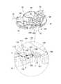
以上の如く構成された震動ドライバドリル1においては、上述した各動作モードで使用する際、整流子モータ9の回転軸12の回転と共に遠心ファン68及び内側ファン69が回転してファン側が負圧となる。よって、前吸気口74から外気が吸い込まれて整流子モータ9を通過した後、排気口73から排出されると共に、上下の吸込部71A,71Bから外気が吸い込まれて整流子13とブラシホルダ70とを通過した後、排気口73から排出される。この空気の流れによって整流子モータ9とブラシホルダ70は冷却されるが、ここでは下側の吸込部71Bは、内リブ82の下側で樹脂ベース78の後方に位置しているため、吸込部71Bから吸い込まれた空気は、下リブ94によって左右に分かれ、図13に実線矢印で示すように、内リブ82の外側を周方向に流れてそれぞれ金属スリーブ79,79側へ向かって上昇する。このとき、樹脂ベース78上のガイドリブ96及び整流用リブ98によって、空気は乱流を起こすことなく上側へ導かれる。特にガイドリブ96と整流用リブ98との上端は金属スリーブ79へ向けた傾斜面96a,98aとなっているので、ガイドリブ96と整流用リブ98との間を通る空気は上側へスムーズに案内される。 When the vibration driver drill 1 configured as described above is used in each of the operation modes described above, the
そして、下側から金属スリーブ79に達した空気の一部は、金属スリーブ79の下側の側壁109に沿って中心側へ向かい、内リブ82の開口88から整流子13の外側を通って前方へ流れるが(矢印a)、残りの一部は、金属スリーブ79の下側に露出する凹溝100,100に端部から進入し(矢印b)、図14及び図6に示すように、ホルダベース102の裏面を通って開口部101から前方へ排出される(矢印c)。この空気の流れによってホルダベース102が冷却される。特に、ホルダベース102の裏面はV字状の切込み106によって表面積が多くなっているため、冷却効果は大きくなる。また、上昇した矢印bの空気は凹溝100の外側の乱流用リブ99に衝突して一旦勢いを弱めるため、空気が凹溝100を通過せず凹溝100に吸い込まれやすくなっている。 A part of the air reaching the
また、このとき、ホルダベース102では、フランジ部105の溝108と透孔107とが凹溝100内に連通しているので、凹溝100に進入した矢印bの空気は、フランジ部105の位置で上下に分岐し(矢印b’)、上側の空気はフランジ部105の上側で溝108を通って透孔107から開口部101に至り、下側の空気はフランジ部105の下側を通って開口部101に至る。これにより、ホルダベース102のフランジ部105の表裏両面と共に上筒103の折り返し部111も効果的に冷却される。特に、凹溝100内で上下に分岐した通気路は、フランジ部105によって流路断面積が狭められているので、フランジ部105を通過する空気の流速が上がり、フランジ部105での放熱効果が高まる。 At this time, in the
一方、上側の吸込部71Aは、内リブ82と外リブ90との間で樹脂ベース78の後方に位置しているため、吸込部71Aから吸い込まれた空気は、上リブ89によって左右に分かれ、図13に点線矢印で示すように傾斜リブ91,91によって左右の金属スリーブ79,79側へ導かれる。ここで、空気の一部は金属スリーブ79の上側の側壁109に沿って中心側へ向かい、内リブ82の開口88から整流子13の外側を通って前方へ流れるが(矢印d)、残りの一部は、金属スリーブ79の上側に露出する凹溝100,100に端部から進入し、ホルダベース102の裏面を通って開口部101から前方へ排出される。この場合も凹溝100に進入した空気は、フランジ部105の位置で上下に分岐してフランジ部105の上下を流れた後、開口部101から排出される。よって、ホルダベース102のフランジ部105の表裏両面と共に上筒103の折り返し部111も効果的に冷却される。また、上側から金属スリーブ79を越えて樹脂ベース78の周方向に流れる空気(矢印e)は、乱流用リブ99に当接して勢いが弱められるため、金属スリーブ79の下側の凹溝100の端部に進入しやすくなる。 On the other hand, since the
このように、上記形態の震動ドライバドリル1によれば、樹脂ベース78に、金属スリーブ79のホルダベース102を金属スリーブ79の保持面と反対側の面に露出させる開口部101を設けたことで、樹脂ベース78における金属スリーブ79の保持面と反対側の面でも空気が金属スリーブ79と接触する。よって、金属スリーブ79の放熱効果が得られて効果的に冷却できる。
特にここでは、整流子モータ9に内側ファン69を設ける一方、ブラシホルダ70を、内側ファン69側に樹脂ベース78が位置する向きで配置して、内側ファン69の回転により、金属スリーブ79側でリヤカバー7に設けた吸込部71A,71Bから吸い込んだ空気がブラシホルダ70及び整流子13を通過して、内側ファン69側で本体ハウジングに設けた排気口73から排出されるようにしたことで、吸込部71A,71Bから吸い込まれた空気がブラシホルダ70を通過する際に開口部101を介してホルダベース102に接触する。よって、金属スリーブ79と内側ファン69との間に樹脂ベース78があっても金属スリーブ79を効果的に冷却することができる。
また、ここでは、樹脂ベース78に、後面側から開口部101に繋がる通気路(凹溝100)を形成しているので、金属スリーブ79の底面で空気流が生じて金属スリーブ79の冷却効果が高まる。Thus, according to the vibration driver drill 1 of the said form, the
In particular, here, the commutator motor 9 is provided with the
Here, since the air passage (concave groove 100) connected to the
また、金属スリーブ79のホルダベース102に、凹溝100内に突出するフランジ部105を設けたことで、凹溝100内の空気流との接触面積が多くなって放熱効果が高まる。さらに、ホルダベース102の裏面には、切込み106による凹凸が形成されているので、ホルダベース102と空気流との接触面積が増大し、より高い放熱効果が得られる。
一方、樹脂ベース78の後面側に、吸込部71A,71Bから吸い込まれた空気が凹溝100の入口近傍で衝突する乱流用リブ99を設けたことで、乱流用リブ99に衝突した空気の勢いが弱められて凹溝100へ進入しやすくなる。
そして、ここでは、樹脂ベース78に、吸込部71Bから吸い込まれた空気を金属スリーブ79側へ案内する整流部(ガイドリブ96及び整流用リブ98)を一体に形成したことで、ガイドリブ96及び整流用リブ98によって導かれる空気により金属スリーブ79を効果的に冷却できると共に、ガイドリブ96及び整流用リブ98を簡単に形成することができる。Further, by providing the
On the other hand, by providing the
In this case, the
なお、上記形態では樹脂ベース78に開口部を設けているが、図15に示すブラシホルダ70Aのように、樹脂ベース78に開口部をなくして、金属スリーブ79のホルダベース102の裏側を通る凹溝100,100のみを設けるようにしてもよい。このように金属スリーブ79のホルダベース102と樹脂ベース78との間に通気路(凹溝100)を形成する場合でも、空気が凹溝100内を通過することでホルダベース102の裏面に接触するため、金属スリーブ79の冷却効果が得られる。 In the above embodiment, the
また、通気路の形態は上記2つの凹溝による場合に限らず、凹溝の数を増減したり断面形状(通路形状)を変えたりすることは可能で、内リブの接線方向でなく周方向に沿って円弧状に形成することもできる。開口部を設ける場合も、数や形状は適宜変更可能である。
金属スリーブも、上筒とホルダベースとが一体となったものであっても差し支えないし、フランジ部がないものも適用できる。金属スリーブの底面に設ける凹凸も、形状の変更は勿論、底面全体でなく開口部の形成部分にのみ部分的に設けることができる。凹凸の省略も可能である。
さらに、金属スリーブの配置形態や樹脂ベースの形状も適宜変更可能であるし、電動工具も震動ドライバドリルに限らず、整流子モータと、ブラシを収容する金属スリーブを樹脂ベースの片面側で保持するブラシホルダとを備えたものであれば、インパクトドライバ等の他の機種にも本発明は適用可能である。The shape of the air passage is not limited to the case of the above two concave grooves, but the number of concave grooves can be increased or decreased, and the cross-sectional shape (passage shape) can be changed. It can also be formed in a circular arc shape along. Also when providing an opening part, a number and a shape can be changed suitably.
The metal sleeve may be one in which the upper tube and the holder base are integrated, and one without a flange portion can also be applied. The unevenness provided on the bottom surface of the metal sleeve can be partially provided not only on the entire bottom surface but also only on the portion where the opening is formed, as well as changing the shape. It is possible to omit the unevenness.
Furthermore, the arrangement form of the metal sleeve and the shape of the resin base can be changed as appropriate, and the electric tool is not limited to the vibration driver drill, and the commutator motor and the metal sleeve for housing the brush are held on one side of the resin base. The present invention can be applied to other models such as an impact driver as long as it includes a brush holder.
1・・震動ドライバドリル、2・・本体、3・・ハンドル、4・・ドリルチャック、5・・バッテリーパック、6・・本体ハウジング、7・・リヤカバー、9・・整流子モータ、10・・固定子、11・・回転子、12・・回転軸、13・・整流子、14・・ギヤアッセンブリ、15・・スピンドル、28・・遊星歯車減速機構、37・・震動機構、38・・クラッチ機構、68・・遠心ファン、69・・内側ファン、70・・ブラシホルダ、71A,71B・・吸込部、72・・後吸気口、73・・排気口、74・・前吸気口、77・・保持溝、78・・樹脂ベース、79・・金属スリーブ、80・・カーボンブラシ、81・・貫通孔、82・・内リブ、98・・整流用リブ、99・・乱流用リブ、100・・凹溝、101・・開口部、102・・ホルダベース、103・・上筒、104・・本体部、105・・フランジ部、107・・透孔、108・・溝。 1 ....
Claims (7)
Translated fromJapanese前記ハウジング内に収容され、ファンを備える整流子モータと、
前記ハウジング内に設けられ、ブラシを収容する金属スリーブと、その金属スリーブを片面側で保持する樹脂ベースとからなるブラシホルダと、を含み、
前記樹脂ベースに、前記金属スリーブを前記片面側と反対側の面に露出させる開口部を設ける一方、
前記ブラシホルダを、前記ファン側に前記樹脂ベースが位置する向きで配置して、前記ファンの回転により、前記金属スリーブ側で前記ハウジングに設けた吸気口から吸い込んだ空気が前記ブラシホルダ及び前記整流子モータの整流子を通過して、前記ファン側で前記ハウジングに設けた排気口から排出されるようにしたことを特徴とする電動工具。A housing;
Is accommodated in thehousing, a commutator motor Ruwith a fan,
A metal sleeve that is provided in the housing and accommodates a brush, and a brush holder that includes a resin base that holds the metal sleeve on one side;
While the resin base,Ru an opening exposing the metal sleeve on the opposite side to the oneside,
The brush holder is disposed in the direction in which the resin base is positioned on the fan side, and the air sucked from the air inlet provided in the housing on the metal sleeve side by the rotation of the fan causes the brush holder and the rectification. An electric tool characterizedin that itpasses through a commutator of a child motor and is discharged from an exhaust port provided in the housing on the fan side .
前記ハウジング内に設けられ、ファンを備えた整流子モータと、
前記ハウジング内に設けられ、ブラシを収容する金属スリーブと、その金属スリーブを片面側で保持する樹脂ベースとからなるブラシホルダと、を備え、
前記ブラシホルダを、前記ファン側に前記樹脂ベースが位置する向きで配置して、前記ファンの回転により、前記金属スリーブ側で前記ハウジングに設けた吸気口から吸い込んだ空気が前記ブラシホルダ及び前記整流子モータの整流子を通過して、前記ファン側で前記ハウジングに設けた排気口から排出される電動工具であって、
前記金属スリーブと前記樹脂ベースとの間に、前記吸気口から吸い込まれた空気が通過する通気路を形成したことを特徴とする電動工具。A housing;
A commutator motor provided in the housing and provided with a fan;
A metal sleeve provided in the housing and containing a brush, and a brush holder comprising a resin base that holds the metal sleeve on one side;
The brush holder is disposed in the direction in which the resin base is positioned on the fan side, and the air sucked from the air inlet provided in the housing on the metal sleeve side by the rotation of the fan causes the brush holder and therectification. A power tool that passes througha commutator of achild motor and is discharged from an exhaust port provided in the housing on the fan side,
An electric tool characterized in that an air passage through which air sucked from the intake port passes is formed between the metal sleeve and the resin base.
前記ハウジング内に設けられ、ファンを備えた整流子モータと、
前記ハウジング内に設けられ、ブラシを収容する金属スリーブと、その金属スリーブを片面側で保持する樹脂ベースとからなるブラシホルダと、を備え、
前記ブラシホルダを、前記ファン側に前記樹脂ベースが位置する向きで配置して、前記ファンの回転により、前記金属スリーブ側で前記ハウジングに設けた吸気口から吸い込んだ空気が前記ブラシホルダ及び前記整流子モータの整流子を通過して、前記ファン側で前記ハウジングに設けた排気口から排出される電動工具であって、
前記樹脂ベースに、前記吸気口から吸い込まれた空気を前記金属スリーブ側へ案内する整流部を一体に形成したことを特徴とする電動工具。A housing;
A commutator motor provided in the housing and provided with a fan;
A metal sleeve provided in the housing and containing a brush, and a brush holder comprising a resin base that holds the metal sleeve on one side;
The brush holder is disposed in the direction in which the resin base is positioned on the fan side, and the air sucked from the air inlet provided in the housing on the metal sleeve side by the rotation of the fan causes the brush holder and therectification. A power tool that passes througha commutator of achild motor and is discharged from an exhaust port provided in the housing on the fan side,
An electric tool characterized in that a rectifying portion for guiding air sucked from the air inlet to the metal sleeve side is integrally formed on the resin base.
Priority Applications (4)
| Application Number | Priority Date | Filing Date | Title |
|---|---|---|---|
| JP2015009690AJP6453658B2 (en) | 2015-01-21 | 2015-01-21 | Electric tool |
| US14/960,844US10270316B2 (en) | 2015-01-21 | 2015-12-07 | Electric power tool |
| DE102016000156.9ADE102016000156A1 (en) | 2015-01-21 | 2016-01-08 | Electric power tool |
| CN201610041377.0ACN105798852B (en) | 2015-01-21 | 2016-01-21 | Electric tool |
Applications Claiming Priority (1)
| Application Number | Priority Date | Filing Date | Title |
|---|---|---|---|
| JP2015009690AJP6453658B2 (en) | 2015-01-21 | 2015-01-21 | Electric tool |
Publications (2)
| Publication Number | Publication Date |
|---|---|
| JP2016135053A JP2016135053A (en) | 2016-07-25 |
| JP6453658B2true JP6453658B2 (en) | 2019-01-16 |
Family
ID=56293840
Family Applications (1)
| Application Number | Title | Priority Date | Filing Date |
|---|---|---|---|
| JP2015009690AActiveJP6453658B2 (en) | 2015-01-21 | 2015-01-21 | Electric tool |
Country Status (4)
| Country | Link |
|---|---|
| US (1) | US10270316B2 (en) |
| JP (1) | JP6453658B2 (en) |
| CN (1) | CN105798852B (en) |
| DE (1) | DE102016000156A1 (en) |
Cited By (1)
| Publication number | Priority date | Publication date | Assignee | Title |
|---|---|---|---|---|
| US20240275243A1 (en)* | 2018-03-02 | 2024-08-15 | Black & Decker Inc. | Power tool |
Families Citing this family (12)
| Publication number | Priority date | Publication date | Assignee | Title |
|---|---|---|---|---|
| WO2018146971A1 (en)* | 2017-02-09 | 2018-08-16 | 日本電産株式会社 | Motor and fan |
| JP6874519B2 (en)* | 2017-05-17 | 2021-05-19 | 株式会社デンソー | DC motor |
| JP6880456B2 (en)* | 2017-10-27 | 2021-06-02 | 株式会社オートネットワーク技術研究所 | Reactor |
| JP7049929B2 (en)* | 2018-06-06 | 2022-04-07 | 株式会社マキタ | Power tools and electric vibration driver drills |
| US11673243B2 (en) | 2018-09-05 | 2023-06-13 | Milwaukee Electric Tool Corporation | Blind rivet nut-setting tool |
| US11267118B2 (en)* | 2018-11-08 | 2022-03-08 | Makita Corporation | Electric power tool |
| JP2020075330A (en)* | 2018-11-08 | 2020-05-21 | 株式会社マキタ | Electric power tool |
| JP7154111B2 (en)* | 2018-11-08 | 2022-10-17 | 株式会社マキタ | Electric tool |
| JP7229807B2 (en)* | 2019-02-21 | 2023-02-28 | 株式会社マキタ | Electric tool |
| US20220379455A1 (en)* | 2019-10-31 | 2022-12-01 | Koki Holdings Co., Ltd. | Electric power tool |
| US20220297255A1 (en)* | 2021-03-18 | 2022-09-22 | X'pole Precision Tools Inc. | Air guider |
| CA3155528A1 (en)* | 2021-04-16 | 2022-10-16 | Max Co., Ltd. | Binding machine |
Family Cites Families (22)
| Publication number | Priority date | Publication date | Assignee | Title |
|---|---|---|---|---|
| US1754222A (en)* | 1928-02-13 | 1930-04-15 | Dorn Electric Tool Company Van | Electric drill |
| US2475560A (en)* | 1945-05-12 | 1949-07-05 | Eureka Williams Corp | Electric motor |
| US2532823A (en)* | 1949-08-25 | 1950-12-05 | Helmut W Schumann | Motor tool |
| US3119942A (en)* | 1960-10-03 | 1964-01-28 | Oster John Mfg Co | Electric motor for hand held appliance |
| GB1093222A (en)* | 1963-04-22 | 1967-11-29 | Kango Electric Hammers Ltd | Improvements relating to electric motors |
| JPS52122803A (en) | 1976-04-09 | 1977-10-15 | Hitachi Ltd | Brush holder |
| GB8526834D0 (en)* | 1985-10-31 | 1985-12-04 | Black & Decker Inc | Electric motors & components |
| US4908538A (en)* | 1989-02-28 | 1990-03-13 | Geberth John Daniel Jun | Totally enclosed electric motor |
| US6133665A (en)* | 1998-08-14 | 2000-10-17 | S-B Power Tool Company | Brush system for electric motors |
| US6552464B1 (en)* | 1999-11-09 | 2003-04-22 | Siemens Canada Limited | Totally integrated engine cooling module for DC motors |
| JP2003153497A (en)* | 2001-11-14 | 2003-05-23 | Asmo Co Ltd | Brush holding device and motor |
| JP4639061B2 (en)* | 2004-07-29 | 2011-02-23 | 株式会社マキタ | Electric tool |
| US7352091B2 (en)* | 2004-09-01 | 2008-04-01 | Remy International, Inc. | Electronic package for electrical machine |
| JP4265571B2 (en)* | 2005-06-01 | 2009-05-20 | 株式会社デンソー | Vehicle alternator |
| US20090121579A1 (en)* | 2007-11-13 | 2009-05-14 | Finkenbinder David B | Curvilinear brush retainer and brushes for an electric motor assembly |
| US7683519B2 (en)* | 2007-11-13 | 2010-03-23 | Ametek, Inc. | Curvilinear brush retainer with liner for an electric motor assembly |
| CN101741167B (en)* | 2008-11-26 | 2013-04-24 | 德昌电机(深圳)有限公司 | Ventilation system and motor thereof |
| JP5075941B2 (en)* | 2010-05-18 | 2012-11-21 | パナソニックEsパワーツール株式会社 | Temperature sensor mounting structure and electric tool for motor with brush |
| CN103460568B (en)* | 2011-06-07 | 2016-01-27 | 三菱电机株式会社 | rotating electrical machine |
| US9093881B2 (en)* | 2012-07-20 | 2015-07-28 | Robert Bosch Gmbh | Plastic brush guide |
| JP6011801B2 (en)* | 2013-02-27 | 2016-10-19 | 日立工機株式会社 | Electric tool |
| US20150194859A1 (en)* | 2013-08-09 | 2015-07-09 | Black & Decker Inc. | Power tool having improved motor fan assembly |
- 2015
- 2015-01-21JPJP2015009690Apatent/JP6453658B2/enactiveActive
- 2015-12-07USUS14/960,844patent/US10270316B2/enactiveActive
- 2016
- 2016-01-08DEDE102016000156.9Apatent/DE102016000156A1/enactivePending
- 2016-01-21CNCN201610041377.0Apatent/CN105798852B/enactiveActive
Cited By (2)
| Publication number | Priority date | Publication date | Assignee | Title |
|---|---|---|---|---|
| US20240275243A1 (en)* | 2018-03-02 | 2024-08-15 | Black & Decker Inc. | Power tool |
| US12413119B2 (en)* | 2018-03-02 | 2025-09-09 | Black & Decker Inc. | Power tool |
Also Published As
| Publication number | Publication date |
|---|---|
| JP2016135053A (en) | 2016-07-25 |
| US20160211730A1 (en) | 2016-07-21 |
| CN105798852A (en) | 2016-07-27 |
| CN105798852B (en) | 2020-01-24 |
| DE102016000156A1 (en) | 2016-07-21 |
| US10270316B2 (en) | 2019-04-23 |
Similar Documents
| Publication | Publication Date | Title |
|---|---|---|
| JP6453658B2 (en) | Electric tool | |
| EP2158063B1 (en) | Power tool | |
| JP6050110B2 (en) | Impact tools | |
| US10040178B2 (en) | Power tool and rotary impact tool | |
| JP5799220B2 (en) | Electric tool | |
| EP2062700B1 (en) | Mid-handle drill construction and assembly process | |
| JP6675188B2 (en) | Power tool with vibration mechanism | |
| CN105846634B (en) | electrical tools | |
| CN115734843A (en) | work machine | |
| JP5983929B2 (en) | Portable blower | |
| CN107206585B (en) | work machine | |
| JP7338705B2 (en) | rotary tool | |
| CN102825585A (en) | Electric tool | |
| JP7193412B2 (en) | Work tools | |
| JP7229807B2 (en) | Electric tool | |
| JP6491904B2 (en) | Electric tool | |
| JP6539513B2 (en) | Electric driver | |
| JP6803364B2 (en) | Electric tool | |
| JP2016165767A (en) | Rotary impact tool | |
| WO2021220991A1 (en) | Work machine and work machine system | |
| JP2020124792A (en) | Electric tool | |
| JP2014061557A (en) | Electric tool | |
| JP6462825B2 (en) | Impact tools | |
| JP6759759B2 (en) | Electric tool | |
| CN114026769A (en) | Electric work machine |
Legal Events
| Date | Code | Title | Description |
|---|---|---|---|
| A621 | Written request for application examination | Free format text:JAPANESE INTERMEDIATE CODE: A621 Effective date:20170718 | |
| A131 | Notification of reasons for refusal | Free format text:JAPANESE INTERMEDIATE CODE: A131 Effective date:20180501 | |
| A977 | Report on retrieval | Free format text:JAPANESE INTERMEDIATE CODE: A971007 Effective date:20180427 | |
| A521 | Request for written amendment filed | Free format text:JAPANESE INTERMEDIATE CODE: A523 Effective date:20180615 | |
| TRDD | Decision of grant or rejection written | ||
| A01 | Written decision to grant a patent or to grant a registration (utility model) | Free format text:JAPANESE INTERMEDIATE CODE: A01 Effective date:20181113 | |
| A61 | First payment of annual fees (during grant procedure) | Free format text:JAPANESE INTERMEDIATE CODE: A61 Effective date:20181213 | |
| R150 | Certificate of patent or registration of utility model | Ref document number:6453658 Country of ref document:JP Free format text:JAPANESE INTERMEDIATE CODE: R150 | |
| R250 | Receipt of annual fees | Free format text:JAPANESE INTERMEDIATE CODE: R250 | |
| R250 | Receipt of annual fees | Free format text:JAPANESE INTERMEDIATE CODE: R250 | |
| R250 | Receipt of annual fees | Free format text:JAPANESE INTERMEDIATE CODE: R250 | |
| R250 | Receipt of annual fees | Free format text:JAPANESE INTERMEDIATE CODE: R250 |