JP6453413B1 - Portable information equipment - Google Patents
Portable information equipmentDownload PDFInfo
- Publication number
- JP6453413B1 JP6453413B1JP2017194112AJP2017194112AJP6453413B1JP 6453413 B1JP6453413 B1JP 6453413B1JP 2017194112 AJP2017194112 AJP 2017194112AJP 2017194112 AJP2017194112 AJP 2017194112AJP 6453413 B1JP6453413 B1JP 6453413B1
- Authority
- JP
- Japan
- Prior art keywords
- support plate
- housing member
- portable information
- hinge
- locking piece
- Prior art date
- Legal status (The legal status is an assumption and is not a legal conclusion. Google has not performed a legal analysis and makes no representation as to the accuracy of the status listed.)
- Active
Links
Images


Classifications
- G—PHYSICS
- G06—COMPUTING OR CALCULATING; COUNTING
- G06F—ELECTRIC DIGITAL DATA PROCESSING
- G06F1/00—Details not covered by groups G06F3/00 - G06F13/00 and G06F21/00
- G06F1/16—Constructional details or arrangements
- G06F1/1613—Constructional details or arrangements for portable computers
- G06F1/1633—Constructional details or arrangements of portable computers not specific to the type of enclosures covered by groups G06F1/1615 - G06F1/1626
- G06F1/1637—Details related to the display arrangement, including those related to the mounting of the display in the housing
- G06F1/1641—Details related to the display arrangement, including those related to the mounting of the display in the housing the display being formed by a plurality of foldable display components
- E—FIXED CONSTRUCTIONS
- E05—LOCKS; KEYS; WINDOW OR DOOR FITTINGS; SAFES
- E05D—HINGES OR SUSPENSION DEVICES FOR DOORS, WINDOWS OR WINGS
- E05D3/00—Hinges with pins
- E05D3/06—Hinges with pins with two or more pins
- E05D3/14—Hinges with pins with two or more pins with four parallel pins and two arms
- G—PHYSICS
- G06—COMPUTING OR CALCULATING; COUNTING
- G06F—ELECTRIC DIGITAL DATA PROCESSING
- G06F1/00—Details not covered by groups G06F3/00 - G06F13/00 and G06F21/00
- G06F1/16—Constructional details or arrangements
- G06F1/1613—Constructional details or arrangements for portable computers
- G06F1/1615—Constructional details or arrangements for portable computers with several enclosures having relative motions, each enclosure supporting at least one I/O or computing function
- G06F1/1616—Constructional details or arrangements for portable computers with several enclosures having relative motions, each enclosure supporting at least one I/O or computing function with folding flat displays, e.g. laptop computers or notebooks having a clamshell configuration, with body parts pivoting to an open position around an axis parallel to the plane they define in closed position
- G—PHYSICS
- G06—COMPUTING OR CALCULATING; COUNTING
- G06F—ELECTRIC DIGITAL DATA PROCESSING
- G06F1/00—Details not covered by groups G06F3/00 - G06F13/00 and G06F21/00
- G06F1/16—Constructional details or arrangements
- G06F1/1613—Constructional details or arrangements for portable computers
- G06F1/1626—Constructional details or arrangements for portable computers with a single-body enclosure integrating a flat display, e.g. Personal Digital Assistants [PDAs]
- G—PHYSICS
- G06—COMPUTING OR CALCULATING; COUNTING
- G06F—ELECTRIC DIGITAL DATA PROCESSING
- G06F1/00—Details not covered by groups G06F3/00 - G06F13/00 and G06F21/00
- G06F1/16—Constructional details or arrangements
- G06F1/1613—Constructional details or arrangements for portable computers
- G06F1/1633—Constructional details or arrangements of portable computers not specific to the type of enclosures covered by groups G06F1/1615 - G06F1/1626
- G06F1/1637—Details related to the display arrangement, including those related to the mounting of the display in the housing
- G06F1/1652—Details related to the display arrangement, including those related to the mounting of the display in the housing the display being flexible, e.g. mimicking a sheet of paper, or rollable
- G—PHYSICS
- G06—COMPUTING OR CALCULATING; COUNTING
- G06F—ELECTRIC DIGITAL DATA PROCESSING
- G06F1/00—Details not covered by groups G06F3/00 - G06F13/00 and G06F21/00
- G06F1/16—Constructional details or arrangements
- G06F1/1613—Constructional details or arrangements for portable computers
- G06F1/1633—Constructional details or arrangements of portable computers not specific to the type of enclosures covered by groups G06F1/1615 - G06F1/1626
- G06F1/1675—Miscellaneous details related to the relative movement between the different enclosures or enclosure parts
- G06F1/1681—Details related solely to hinges
- H—ELECTRICITY
- H04—ELECTRIC COMMUNICATION TECHNIQUE
- H04M—TELEPHONIC COMMUNICATION
- H04M1/00—Substation equipment, e.g. for use by subscribers
- H04M1/02—Constructional features of telephone sets
- H04M1/0202—Portable telephone sets, e.g. cordless phones, mobile phones or bar type handsets
- H04M1/026—Details of the structure or mounting of specific components
- H04M1/0266—Details of the structure or mounting of specific components for a display module assembly
- H04M1/0268—Details of the structure or mounting of specific components for a display module assembly including a flexible display panel
- E—FIXED CONSTRUCTIONS
- E05—LOCKS; KEYS; WINDOW OR DOOR FITTINGS; SAFES
- E05Y—INDEXING SCHEME ASSOCIATED WITH SUBCLASSES E05D AND E05F, RELATING TO CONSTRUCTION ELEMENTS, ELECTRIC CONTROL, POWER SUPPLY, POWER SIGNAL OR TRANSMISSION, USER INTERFACES, MOUNTING OR COUPLING, DETAILS, ACCESSORIES, AUXILIARY OPERATIONS NOT OTHERWISE PROVIDED FOR, APPLICATION THEREOF
- E05Y2999/00—Subject-matter not otherwise provided for in this subclass
- H—ELECTRICITY
- H04—ELECTRIC COMMUNICATION TECHNIQUE
- H04B—TRANSMISSION
- H04B1/00—Details of transmission systems, not covered by a single one of groups H04B3/00 - H04B13/00; Details of transmission systems not characterised by the medium used for transmission
- H04B1/38—Transceivers, i.e. devices in which transmitter and receiver form a structural unit and in which at least one part is used for functions of transmitting and receiving
- H04B1/3827—Portable transceivers
Landscapes
- Engineering & Computer Science (AREA)
- Theoretical Computer Science (AREA)
- Computer Hardware Design (AREA)
- Physics & Mathematics (AREA)
- Human Computer Interaction (AREA)
- General Engineering & Computer Science (AREA)
- General Physics & Mathematics (AREA)
- Mathematical Physics (AREA)
- Mechanical Engineering (AREA)
- Signal Processing (AREA)
- Telephone Set Structure (AREA)
- Casings For Electric Apparatus (AREA)
Abstract
Translated fromJapaneseDescription
Translated fromJapanese本発明は、折り畳み可能な一対の筐体部材の内側に折り畳み可能なディスプレイを設けた携帯用情報機器に関する。 The present invention relates to a portable information device provided with a foldable display inside a pair of foldable casing members.
近年、タッチパネル式の液晶ディスプレイを有し、物理的なキーボードを持たないタブレット型PCやスマートフォン等の携帯用情報機器が急速に普及している。この種の携帯用情報機器のディスプレイは、使用時には大きい方が望ましい反面、携帯時には小型化されることが望まれている。そこで、有機EL(Electro Luminescence)等のフレキシブルディスプレイを用いることで、筐体だけでなくディスプレイまでも折り畳み可能に構成した携帯用情報機器も提案されている(例えば、特許文献1参照)。 In recent years, portable information devices such as tablet PCs and smartphones that have a touch panel type liquid crystal display and do not have a physical keyboard are rapidly spreading. The display of this type of portable information device is desirably larger when used, but is desired to be downsized when carried. Therefore, a portable information device that can be folded not only to the housing but also to the display by using a flexible display such as an organic EL (Electro Luminescence) has been proposed (for example, see Patent Document 1).
上記のようなフレキシブルディスプレイは非常に薄く、衝撃等にも弱い。このため、フレキシブルディスプレイは二つ折りに可動する筐体部材の内面側で安定して支持されている必要がある。そこで、例えばフレキシブルディスプレイを支持するための支持部材を筐体部材の内面側に設けることが考えられる。ところが、この支持部材も二つ折りに可動する必要があり、その折曲部に段差等を生じると、ディスプレイが湾曲して製品不良を生じる可能性がある。 The flexible display as described above is very thin and vulnerable to impacts. For this reason, the flexible display needs to be stably supported on the inner surface side of the housing member movable in two. Thus, for example, it is conceivable to provide a support member for supporting the flexible display on the inner surface side of the housing member. However, this support member also needs to be movable in two, and if a step or the like is generated in the bent portion, the display may be bent to cause a product defect.
本発明は、上記従来技術の課題を考慮してなされたものであり、折り畳み可能なディスプレイを安定して支持することができる携帯用情報機器を提供することを目的とする。 The present invention has been made in view of the above-described problems of the prior art, and an object thereof is to provide a portable information device that can stably support a foldable display.
本発明の一態様に係る携帯用情報機器は、二つ折りに折り畳み可能な第1筐体部材及び第2筐体部材と、前記第1筐体部材と前記第2筐体部材の内面間に亘って設けられ、二つ折りに折り畳み可能なディスプレイと、前記第1筐体部材の内面側に配置され、前記第1筐体部材側で前記ディスプレイの裏面を支持する第1支持プレートと、前記第2筐体部材の内面側に配置され、前記第2筐体部材側で前記ディスプレイの裏面を支持する第2支持プレートと、前記第1支持プレートに設けられ、該第1支持プレートの一端面側から突出しており、前記第1筐体部材と前記第2筐体部材とが開閉された場合に前記第2支持プレートに対して接離する第1係止片と、前記第2支持プレートに設けられ、該第2支持プレートの一端面側から突出しており、前記第1筐体部材と前記第2筐体部材とが開閉された場合に前記第1支持プレートに対して接離する第2係止片と、を備える。 A portable information device according to one embodiment of the present invention includes a first housing member and a second housing member that can be folded in two, and an inner surface of the first housing member and the second housing member. A display that can be folded in two, a first support plate that is disposed on the inner surface side of the first housing member and supports the back surface of the display on the first housing member side, and the second A second support plate disposed on the inner surface side of the housing member and supporting the back surface of the display on the second housing member side; and provided on the first support plate, from one end surface side of the first support plate A first locking piece that protrudes and contacts and separates from the second support plate when the first housing member and the second housing member are opened and closed; and provided on the second support plate , Protruding from one end surface side of the second support plate , And a second locking piece approaching and moving away from relative to said first support plate when said first housing member and the second casing member is opened and closed.
このような構成によれば、各支持プレートから突出した各係止片が相手側の支持プレートに対して当接する。これにより、筐体部材間を平板状に開いた際、各支持プレートに当接した係止片同士が互いに規制し合って吊り合い、2枚の支持プレート間が平坦に形成される。これにより、当該携帯用情報機器は、支持プレートの対向する一端面間での段差の発生を抑制してディスプレイを安定して支持することができる。 According to such a configuration, each locking piece protruding from each support plate comes into contact with the counterpart support plate. As a result, when the housing members are opened in a flat plate shape, the locking pieces that are in contact with the respective support plates are regulated and suspended from each other, and the two support plates are formed flat. Thereby, the said portable information device can suppress the generation | occurrence | production of the level | step difference between the one end surfaces which a support plate opposes, and can support a display stably.
前記第1係止片は、前記第1支持プレートの一端面に沿って複数設けられ、前記第2係止片は、前記第1係止片と互い違いに対向する位置で、前記第2支持プレートの一端面に沿って複数設けられた構成であってもよい。そうすると、各支持プレートの一端面に沿った方向での段差の発生をより確実に防止できる。 A plurality of the first locking pieces are provided along one end surface of the first support plate, and the second locking pieces are positioned opposite to the first locking pieces at the second support plate. The structure provided with two or more along the one end surface may be sufficient. If it does so, generation | occurrence | production of the level | step difference in the direction along the one end surface of each support plate can be prevented more reliably.
前記第1係止片は、基端側が前記第1支持プレートの裏面側に設けられ、前記第2係止片は、基端側が前記第2支持プレートの裏面側に設けられ、前記第1筐体部材と前記第2筐体部材とを開いて平板状に構成した状態で、前記第1係止片は、先端側の表面が前記第2支持プレートの裏面又は該裏面に形成された凹部の底面に当接し、前記第2係止片は、先端側の表面が前記第1支持プレートの裏面又は該裏面に形成された凹部の底面に当接する構成であってもよい。 The first locking piece is provided on the back side of the first support plate on the base end side, and the base end side of the second locking piece is provided on the back side of the second support plate. In a state where the body member and the second housing member are opened and configured in a flat plate shape, the first locking piece has a front surface on the back surface of the second support plate or a recess formed on the back surface. The second locking piece may be in contact with the bottom surface, and the front end surface may be in contact with the back surface of the first support plate or the bottom surface of the recess formed on the back surface.
前記第1係止片は、前記第1支持プレートの一端面から突出しており、前記第2係止片は、前記第2支持プレートの一端面から突出しており、前記第1筐体部材と前記第2筐体部材とを開いて平板状に構成した状態で、前記第1係止片は、先端側の表面が前記第2支持プレートの裏面に形成された凹部の底面又は前記第2支持プレートの一端面に開口形成された穴部の天面に当接し、前記第2係止片は、先端側の表面が前記第1支持プレートの裏面に形成された凹部の底面又は前記第1支持プレートの一端面に開口形成された穴部の天面に当接する構成であってもよい。 The first locking piece protrudes from one end face of the first support plate, the second locking piece protrudes from one end face of the second support plate, and the first housing member and the In a state where the second housing member is opened and configured in a flat plate shape, the first locking piece has a front surface on the bottom surface of a recess formed on the back surface of the second support plate or the second support plate. The second locking piece is in contact with the top surface of the hole formed in one end surface of the first end surface, and the bottom surface of the recess formed on the back surface of the first support plate or the first support plate The structure which contact | abuts to the top | upper surface of the hole part formed by opening in the one end surface of this may be sufficient.
前記第1筐体部材及び前記第2筐体部材を開いて平板状に構成した状態で、前記第1支持プレートの一端面が前記第2支持プレートの一端面と当接配置される構成であってもよい。そうすると、ディスプレイは、その裏面が段差なく1枚板状に構成された支持プレートによって一層安定して支持される。 In a state where the first casing member and the second casing member are opened and configured in a flat plate shape, one end surface of the first support plate is disposed in contact with one end surface of the second support plate. May be. If it does so, the display will be supported more stably by the support plate by which the back surface was comprised without the level | step difference at one plate shape.
前記第1筐体部材と前記第2筐体部材とは、隣接配置された一縁部同士がヒンジ機構によって連結されることで二つ折りに折り畳み可能であり、前記ヒンジ機構は、前記第1筐体部材の内面に固定され、表面に前記第1支持プレートが支持される第1ヒンジ筐体と、前記第2筐体部材の内面に固定され、表面に前記第2支持プレートが支持される第2ヒンジ筐体と、前記第1ヒンジ筐体と前記第2ヒンジ筐体の間を回動可能に連結するヒンジ軸と、を有する構成であってもよい。そうすると、例えば各支持プレートの一端面に沿う方向での両端部に設けたヒンジ機構で各支持プレートの両端部が支持されるため、各支持プレートの一端面に沿った方向での段差の発生をより確実に防止できる。 The first casing member and the second casing member can be folded in two by connecting adjacent edges of the first casing member and the second casing member by a hinge mechanism. A first hinge housing fixed to the inner surface of the body member and supported on the surface by the first support plate; and a first hinge housing fixed to the inner surface of the second housing member and supported on the surface by the second support plate. The structure which has 2 hinge housing | casings and the hinge axis | shaft which connects between the said 1st hinge housing | casing and the said 2nd hinge housing | casing so that rotation is possible may be sufficient. Then, for example, since both end portions of each support plate are supported by hinge mechanisms provided at both end portions in the direction along one end surface of each support plate, a step in the direction along one end surface of each support plate is generated. It can be prevented more reliably.
前記第1筐体部材と前記第2筐体部材とは、隣接配置された一縁部同士がヒンジ機構によって連結されることで二つ折りに折り畳み可能であり、前記ヒンジ機構は、前記第1筐体部材と前記第2筐体部材との内面間に亘って設けられる第1リンク部材及び第2リンク部材を有し、前記第1リンク部材は、一端側が前記第1筐体部材に第1ヒンジ軸を介して回動可能に連結され、他端側が前記第2筐体部材に第2ヒンジ軸を介して回動可能に連結されており、前記第2リンク部材は、一端側が前記第1筐体部材に第3ヒンジ軸を介して回動可能に連結され、他端側が前記第2筐体部材に第4ヒンジ軸を介して回動可能に連結されており、前記第1ヒンジ軸、前記第2ヒンジ軸、前記第3ヒンジ軸及び前記第4ヒンジ軸は、前記第1筐体部材から前記第2筐体部材に向かう方向で、前記第1ヒンジ軸、前記第3ヒンジ軸、前記第2ヒンジ軸、前記第4ヒンジ軸の順に並んでいる構成であってもよい。そうすると、例えば筐体部材間を閉じた状態から開く際、各支持プレートの一端面間が略水平方向に接離するため、各係止片をより円滑に且つ干渉することなく相手側の支持プレートに対して裏面側から接離させることが可能となる。 The first casing member and the second casing member can be folded in two by connecting adjacent edges of the first casing member and the second casing member by a hinge mechanism. A first link member and a second link member provided between inner surfaces of the body member and the second casing member, wherein the first link member has a first hinge on one end side of the first casing member. The other end side is rotatably connected to the second housing member via a second hinge shaft, and one end side of the second link member is connected to the first housing. The body member is pivotally connected via a third hinge shaft, and the other end is pivotally connected to the second housing member via a fourth hinge shaft, the first hinge shaft, The second hinge shaft, the third hinge shaft, and the fourth hinge shaft are separated from the first housing member. In the direction towards the serial second housing member, said first hinge axis, the third hinge axis, the second hinge axis may be configured in a row in the order of the fourth hinge shaft. In this case, for example, when the housing members are opened from a closed state, the one end surfaces of the support plates are contacted and separated in a substantially horizontal direction, so that each locking piece is more smoothly and without interfering with each other. It is possible to contact and separate from the back side.
本発明の上記態様によれば、折り畳み可能なディスプレイを安定して支持することができる携帯用情報機器が得られる。 According to the aspect of the present invention, a portable information device that can stably support a foldable display can be obtained.
以下、本発明に係る携帯用情報機器について好適な実施形態を挙げ、添付の図面を参照しながら詳細に説明する。 Hereinafter, preferred embodiments of a portable information device according to the present invention will be described in detail with reference to the accompanying drawings.
1.携帯用情報機器の全体構成の説明
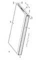
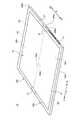
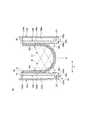
図1は、本発明の一実施形態に係る携帯用情報機器10を閉じて収納形態とした状態を示す斜視図である。図2は、図1に示す携帯用情報機器10を開いて使用形態とした状態を模式的に示す斜視図である。図3は、図2に示す携帯用情報機器10の内部構造を模式的に示した平面図である。1. Description of Overall Configuration of Portable Information Device FIG. 1 is a perspective view showing a state in which a
図1及び図2に示すように、携帯用情報機器10は、第1筐体部材12A及び第2筐体部材12Bと、背表紙部材14と、ディスプレイ16とを備える。本実施形態では、携帯用情報機器10として本のように二つ折りに折り畳み可能なタブレット型PCを例示する。携帯用情報機器10は携帯電話、スマートフォン、電子手帳又は携帯用ゲーム機等であってもよい。 As shown in FIGS. 1 and 2, the
各筐体部材12A,12Bは、それぞれ背表紙部材14に対応する辺以外の3辺に側壁を起立形成した矩形の板状部材である。各筐体部材12A,12Bは、例えばステンレスやマグネシウム、アルミニウム等の金属板、或いは炭素繊維等の強化繊維を含む繊維強化樹脂板等で構成される。筐体部材12A,12Bの内面側には、第1支持プレート18A及び第2支持プレート18Bを介してディスプレイ16が固定される。筐体部材12A,12B間は、背表紙部材14の両端部に設けられた一対のヒンジ機構19,19を介して連結されている。ヒンジ機構19は、筐体部材12A,12B間を図1に示す収納形態と図2に示す使用形態とに折り畳み可能に連結している。図3中に1点鎖線で示す線Cは、筐体部材12A,12Bの折り畳み動作の中心となる折曲中心Cを示している。 Each housing member 12 </ b> A, 12 </ b> B is a rectangular plate-like member in which side walls are erected on three sides other than the side corresponding to the
各筐体部材12A,12Bは、背表紙部材14側の内端面(一端面)12Aa,12Baがヒンジ側となり、背表紙部材14側とは反対側の外端面12Ab,12Bbが開放端部側となる。 In each
以下、図1〜図3に示すように、携帯用情報機器10について、中央の背表紙部材14から外端面12Ab,12Bbに向かう方向をX方向、背表紙部材14の長手方向に沿う方向をY方向と呼んで説明する。X方向については、背表紙部材14から一方の外端面12Abに向かう方向をX1方向、他方の外端面12Bbに向かう方向をX2方向と呼ぶこともある。同様にY方向については、背表紙部材14の長手方向で一方側(図3中で上側)に向かう方向をY1方向、他方側(図3中で下側)に向かう方向をY2方向と呼ぶこともある。 Hereinafter, as shown in FIGS. 1 to 3, for the
図2及び図3に示すように、第1筐体部材12Aの内面12Acには第1支持プレート18Aが取付固定され、第2筐体部材12Bの内面12Bcには第2支持プレート18Bが取付固定されている。各筐体部材12A,12Bの内面12Ac,12Bc上であって支持プレート18A,18Bの裏面側となる位置には、基板、通信モジュール、バッテリ装置、冷却装置等の各種部品が取付固定されている。 2 and 3, the
ディスプレイ16は、例えばタッチパネル式の液晶ディスプレイである。ディスプレイ16は、筐体部材12A,12Bを折り畳んだ際に一緒に折り畳み可能な構造である。ディスプレイ16は、支持プレート18A,18Bを介して筐体部材12A,12Bの内面12Ac,12Bc側に取付固定される。ディスプレイ16は、例えば柔軟性の高いペーパー構造を持った有機EL等のフレキシブルディスプレイであり、筐体部材12A,12Bの開閉動作に伴って開閉する。 The
背表紙部材14は、可撓性を持った薄い板状部材で形成され、携帯用情報機器10を折り畳んだ際の背表紙となる。背表紙部材14は内端面12Aa,12Ba間を内側から覆うように筐体部材12A,12B間に亘って設けられている。図1に示すように、携帯用情報機器10は、収納形態では、筐体部材12A,12Bの内端面12Aa,12Ba間が大きく離間して隙間を生じる。背表紙部材14は、この内端面12Aa,12Ba間の隙間を覆うことで、内部のディスプレイ16や各種部品が露呈することを防止している。 The
2.支持プレートの説明
ディスプレイ16を支持する支持プレート18A,18Bの構成例を説明する。図4Aは、図3中のIVA−IVA線に沿う模式断面図である。図4Bは、図3中のIVB−IVB線に沿う模式断面図である。2. Description of Support Plate A configuration example of the
図4A及び図4Bに示すように、支持プレート18A,18Bは、その表面側でディスプレイ16を支持するプレート部材である。各支持プレート18A,18Bは、各筐体部材12A,12Bの内面12Ac,12Bc上にそれぞれ固定され、折曲中心Cを中心として本のように開閉される。本実施形態の場合、支持プレート18A,18Bは、シート状部材20を介してディスプレイ16を支持している。 As shown in FIGS. 4A and 4B, the
各支持プレート18A,18Bは、例えばステンレスやマグネシウム、アルミニウム等の金属板、或いは炭素繊維等の強化繊維を熱硬化性樹脂や熱可塑性樹脂からなるマトリクス樹脂に含浸させた繊維強化樹脂板等で構成される。本実施形態では、支持プレート18A,18Bは、炭素繊維を強化樹脂とした炭素繊維強化樹脂板で形成している。本実施形態の支持プレート18A,18Bは、筐体部材12A,12B間を平板状に開いた使用形態で、その隣接する内端面(一端面)18Aa,18Ba同士が当接する(図4A及び図6A参照)。支持プレート18A,18Bは、筐体部材12A,12B間を二つ折りに折り畳んだ収納形態では、内端面18Aa,18Ba同士が離間する(図6C参照)。 Each of the
シート状部材20は、薄い樹脂膜や金属箔のような可撓性を持った材質で構成された薄膜である。シート状部材20は、左右の支持プレート18A,18B間に亘ってその表面全域に配置されている。シート状部材20は、裏面が接着剤や両面テープ等を用いて支持プレート18A,18Bの表面に貼付固定されている。シート状部材20は、内端面18Aa,18BaをX方向に跨ぐ一部分(X方向が短辺でY方向が長辺となる帯状部分)は、支持プレート18A,18Bの表面に対して固着されない非接着部となっている(図6C参照)。シート状部材20は、この非接着部が支持プレート18A,18B間の折曲部(フレキシブルヒンジ)として機能する。 The sheet-
ディスプレイ16は、その裏面の略全域が接着剤や両面テープ等を用いてシート状部材20の表面に貼付固定されている。図2に示すように、ディスプレイ16は、その表面の外周縁部にベゼル部材21が配設される。ベゼル部材21は、ディスプレイ16の表面の表示領域(アクティブ領域)R1を除く外周縁部の非表示領域(非アクティブ領域)R2を覆うように設けられる。なお、ディスプレイ16は、シート状部材20を用いずに直接的に支持プレート18A,18Bの表面に貼付固定されてもよい。この構成の場合、ディスプレイ16は、内端面18Aa,18BaをX方向に跨ぐ一部分が、支持プレート18A,18Bに固着されない非接着部となる。 The
図3に示すように、支持プレート18A,18Bの内端面18Aa,18Ba間には、複数の第1係止片22及び第2係止片23を有する端面間位置決め部24が設けられている。 As shown in FIG. 3, an end-to-
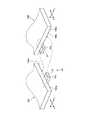
図5は、端面間位置決め部24の構成を模式的に示す要部拡大斜視図である。図5は、第1支持プレート18Aの内端面18Aaと第2支持プレート18Bの内端面18Baとを扇状に展開した説明図である。 FIG. 5 is an enlarged perspective view of a main part schematically showing the configuration of the end
図3〜図5に示すように、第1係止片22は、第1支持プレート18Aの裏面18Abに固定された板片状部材である。第1係止片22は、第1支持プレート18Aの内端面18Aaに沿って所定間隔で複数枚(図3では5枚)並んでいる。第1係止片22の基端側は、裏面18Abと一体に形成され或いは裏面18Abに対して接着剤や両面テープを用いて接着固定されている。第1係止片22の先端側は、内端面18Aa,18Baを跨いでX2方向に突出し、第2支持プレート18Bの裏面18Bbに当接可能な位置まで延びている。第1係止片22は、筐体部材12A,12Bをヒンジ機構19で開閉させた場合に、内端面18Aaより突出した先端側の表面22aが第2支持プレート18Bの裏面18Bbに対して裏面18Bb側から接離する。 As shown in FIGS. 3 to 5, the
第2係止片23は、第2支持プレート18Bの裏面18Bbに固定された板片状部材である。第2係止片23は、第2支持プレート18Bの内端面18Baに沿って所定間隔で複数枚(図3では4枚)並んでおり、隣り合う第1係止片22,22間に介在するように配置されている。第2係止片23の基端側は、裏面18Bbと一体に形成され或いは裏面18Bbに対して例えば接着剤や両面テープを用いて接着固定されている。第2係止片23の先端側は、内端面18Ba,18Aaを跨いでX1方向に突出し、第1支持プレート18Aの裏面18Abに当接可能な位置まで延びている。第2係止片23は、筐体部材12A,12Bをヒンジ機構19で開閉させた場合に、内端面18Baより突出した先端側の表面23aが第1支持プレート18Aの裏面18Abに対して裏面18Ab側から接離する。 The
このように、係止片22,23は、Y方向にそれぞれ互い違いに並んでX方向で対向方向に突出することで、内端面18Aa,18Baを挟んで櫛歯を互いに噛み合いさせた構造を構築し、それぞれの表面22a,23aが相手側の支持プレート18A,18Bの裏面18Ab,18Bbに接離する。 In this way, the locking
図3に示すように、支持プレート18A,18Bは、その外周縁部から突出した複数の取付片25,26を介して筐体部材12A,12Bの内面12Ac,12Bcに取付固定されている。取付片25,26は、支持プレート18A,18Bの外周端面から外方に突出した突出片である。取付片25は、ヒンジ機構19と重なる位置に設けられている。取付片26は、支持プレート18A,18Bの外周縁部の適宜位置に複数設けられている。取付片25,26は、中央にねじ止め用の貫通孔が形成されている。支持プレート18A,18Bは、各取付片25,26の貫通孔を通した取付ねじ27によって筐体部材12A,12Bの内面12Ac,12Bcに締結固定される。この際、取付片25は、後述するヒンジ筐体28A,28Bの表面28Aa,28Baに当接配置された状態でヒンジ筐体28A,28Bに対して取付ねじ27によって締結される。筐体部材12A,12Bの内面12Ac,12Bcには、取付ねじ27を螺合させる雌ねじを設けたボスを設けてもよい。 As shown in FIG. 3, the
3.ヒンジ機構の説明
筐体部材12A,12B間を連結するヒンジ機構19の構成例を説明する。ヒンジ機構19は、以下のような多軸ヒンジではなく、1軸或いは2軸ヒンジで構成されてもよい。3. Description of Hinge Mechanism A configuration example of the
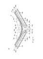
図3に示すように、ヒンジ機構19は、筐体部材12A,12B間に跨るようにY方向両端部にそれぞれ配設されている。各ヒンジ機構19は、ディスプレイ16の外形の外側となる位置に設けられ、Y方向中心を通るX方向の直線を基準として互いに線対称構造である。各ヒンジ機構19は、第1ヒンジ筐体28Aと、第2ヒンジ筐体28Bと、第1リンク部材30と、第2リンク部材31とを有する。 As shown in FIG. 3, the
各ヒンジ筐体28A,28Bは、樹脂や金属等で形成された薄型ブロック状の部品である。第1ヒンジ筐体28Aは、第1筐体部材12Aの内面12Ac上に固定ねじ32を用いて固定される。第2ヒンジ筐体28Bは、第2筐体部材12Bの内面12Bc上に固定ねじ32を用いて固定される。 Each of the
第1リンク部材30は、一端部が第1ヒンジ筐体28Aに対して第1ヒンジ軸36aを介して回動可能に連結され、他端部が第2ヒンジ筐体28Bに対して第2ヒンジ軸36bを介して回動可能に連結される(図6A参照)。第2リンク部材31は、一端部が第1ヒンジ筐体28Aに対して第3ヒンジ軸36cを介して回動可能に連結され、他端部が第2ヒンジ筐体28Bに対して第4ヒンジ軸36dを介して回動可能に連結される(図6A参照)。第1リンク部材30と第2リンク部材31は、Y方向に並列されている。第1リンク部材30の第2ヒンジ軸36bは、第2リンク部材31の第3ヒンジ軸36cと第4ヒンジ軸36dの間に挟まれた位置にある。第2リンク部材31の第3ヒンジ軸36cは、第1リンク部材30の第1ヒンジ軸36aと第2ヒンジ軸36bの間に挟まれた位置にある。これにより、第1リンク部材30と第2リンク部材31は、X方向及びY方向に位置ずれして互い違いに並んでいる。 One end of the
各ヒンジ機構19は、筐体部材12A,12B間が折曲中心Cを中心に折り畳まれると、各ヒンジ軸36a〜36dを介して各リンク部材30,31が回動する(図6A〜図6C参照)。これにより、ヒンジ機構19は、筐体部材12A,12B間を二つ折りに折り畳んだ状態から平板状に開いた状態まで開閉可能に連結している。 In each
4.携帯用情報機器の開閉動作及び作用効果の説明
携帯用情報機器10の開閉動作について説明する。図6Aは、筐体部材12A,12B間を開いた状態での支持プレート18A,18B及びヒンジ機構19の位置関係を模式的に示す側面断面図である。図6Bは、図6Aに示す状態から筐体部材12A,12B間を閉じ動作させた状態での側面断面図である。図6Cは、図6Bに示す状態から筐体部材12A,12B間を閉じ動作させて二つ折りに折り畳んだ状態での側面断面図である。4). Description of Opening / Closing Operation and Effects of Portable Information Device The opening / closing operation of the
本実施形態の携帯用情報機器10は、図6Aに示すように筐体部材12A,12B間を平板状に開いた使用形態では、ヒンジ軸36a〜36dの軸中心が同一平面上に配置され、この位置にディスプレイ16の表面が一致する。この使用形態から筐体部材12A,12B間を折り畳み動作させると、図6Bに示すように各リンク部材30,31が各ヒンジ軸36a〜36dを中心に回動して筐体部材12A,12B間が次第に折り畳まれ、ディスプレイ16も折り曲げされる。最終的には、図6Cに示すように各筐体部材12A,12B間が二つ折りに折り畳まれ、ディスプレイ16も所定曲率の円弧を描いた二つ折りに折り畳まれた収納形態となる。 In the
この開閉動作に際し、第1係止片22は、内端面18Aaより突出している表面22aが、図6Aに示す使用形態では第2支持プレート18Bの裏面18Bbに当接し、図6Cに示す収納形態では裏面18Bbから離間する。同様に、第2係止片23は、内端面18Baより突出している表面23aが、図6Aに示す使用形態では第1支持プレート18Aの裏面18Abに当接し、図6Cに示す収納形態では裏面18Abから離間する。すなわち、携帯用情報機器10は、図6Cに示す収納形態から図6Aに示す使用形態に開かれる際、各係止片22,23の表面22a,23aのそれぞれが、対向する支持プレート18B,18Aの裏面18Bb,18Abに下方から当接し、この裏面18Bb,18Abを押し上げる方向へと押圧する。その結果、各係止片22,23からの各支持プレート18B,18Aに対する押上力が互いに規制し合い、各支持プレート18A,18Bの内端面18Aa,18Ba間が板厚方向で段差を生じることなく平坦化されて安定する。 In this opening / closing operation, the
すなわち、支持プレート18A,18Bは、筐体部材12A,12Bの開閉動作に伴って二つ折り可能なように互いに別体に構成されている。このため、仮に使用形態時に支持プレート18A,18B間で板厚方向の段差を生じると、その表面に設けられるディスプレイ16にこの段差の影響が出る。その結果、使用形態でディスプレイ16が湾曲或いは波打ちし、視認不良や表示不良等の製品不良を生じる可能性がある。またディスプレイ16が湾曲等を生じていると、使用形態と収納形態との開閉動作時にディスプレイ16が設計上の開閉軌道で可動しない可能性がある。そうすると、ディスプレイ16は、特に折曲部及びその付近で過度な負荷を受け、破損や不良を生じる懸念もある。 That is, the
そこで、当該携帯用情報機器10では、各支持プレート18A,18Bから突出した各係止片22,23が相手側の裏面18Bb,18Abに当接して互いに規制し合って吊り合う端面間位置決め部24を備える。これにより、当該携帯用情報機器10は、使用形態での支持プレート18A,18Bの内端面18Aa,18Ba間での段差の発生を抑制し、ディスプレイ16を安定して支持することができる。その結果、ディスプレイ16が不具合を生じることが防止される。第1係止片22と第2係止片23の組は、少なくとも1組設ければよい。 Accordingly, in the
当該携帯用情報機器10では、係止片22,23は、内端面18Aa,18Baに沿って互い違いに複数設けられている。このため、内端面18Aa,18Baの延在方向での段差の発生をより確実に防止できる。 In the
当該携帯用情報機器10では、支持プレート18A,18Bの取付片25がヒンジ筐体28A,28Bの表面28Aa,28Baにそれぞれ当接支持されている。このため、当該携帯用情報機器10は、例えば各ヒンジ筐体28A,28Bの表面28Aa,28Baを同一平面状に揃えることで、各支持プレート18A,18Bの内端面18Aa,18BaのY方向両端部に段差ができることを防止できる。その結果、使用形態での内端面18Aa,18Ba間での段差の発生を一層確実に抑制してディスプレイ16を一層安定して支持することができる。 In the
当該携帯用情報機器10では、支持プレート18A,18Bは、筐体部材12A,12Bを開いて平板状に構成した使用形態で互いに対向する内端面18Aa,18Ba同士が当接配置される。このため、支持プレート18A,18Bは、開かれた際に1枚板状に構成される。その結果、ディスプレイ16が一層安定して支持される。また、支持プレート18A,18Bは、携帯用情報機器10の使用形態で内端面18Aa,18Ba間に隙間を生じないため、ディスプレイ16のタッチ操作等に対する支持剛性も担保される。 In the
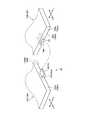
図7は、第1変形例に係る端面間位置決め部40の構成を模式的に示す要部拡大斜視図である。図7は、図5と同様に第1支持プレート18Aの内端面18Aaと第2支持プレート18Bの内端面18Baとを扇状に展開した説明図であり、図8も同様である。 FIG. 7 is an enlarged perspective view of a main part schematically showing a configuration of the end-to-end
図7に示すように、この端面間位置決め部40は、図5に示す端面間位置決め部24の第1係止片22及び第2係止片23に代えて、第1係止片42及び第2係止片43を備える。 As shown in FIG. 7, this end-to-
第1係止片42は、第1支持プレート18Aの内端面18Aaから突出した板片状部材である。第1係止片42の配置や設置枚数は、図3に示す第1係止片22と同様でよい。第1係止片42の基端側は、例えば内端面18Aaと一体に形成され或いは内端面18Aaに嵌合構造を用いて固定されている。第1係止片42の先端側は、内端面18Aa,18Baを跨いでX2方向に突出し、第2支持プレート18Bの裏面18Bbに形成された凹部44に挿抜可能な位置まで延びている。凹部44は、裏面18Bbに形成され、内端面18Ba及び下方が開口している。これにより、第1係止片42は、筐体部材12A,12Bを開閉させた場合に、内端面18Aaより突出した先端側の表面42aが凹部44の底面(天面)44aに対して裏面18Bb側から接離する。 The
第2係止片43は、第2支持プレート18Bに設けられると共に、第1係止片42と互い違いに並列されている以外は第1係止片42と同様な構成である。そこで、第2係止片43及びその表面43aについては、図7中に参照符号を第1係止片42及びその表面42aにかっこ書きで併記することで詳細な図面及び説明を省略する。すなわち第2係止片43は、筐体部材12A,12Bを開閉させた場合に、内端面18Baより突出した先端側の表面43aが第1支持プレート18Aの裏面18Abに形成された凹部44の底面(天面)44aに対して裏面18Ab側から接離する。 The
このような端面間位置決め部40は、図5に示す端面間位置決め部24に比べて各係止片42,43の厚みが各支持プレート18A,18Bの裏面18Ab,18Bb側に現れない。このため、係止片42,43を含めた支持プレート18A,18Bの厚みを低減できる。凹部44は、図5に示す端面間位置決め部24の係止片22,23の当接部として利用してもよい。 In such an end-to-
図8は、第2変形例に係る端面間位置決め部50の構成を模式的に示す要部拡大斜視図である。 FIG. 8 is an enlarged perspective view of a main part schematically showing the configuration of the end
図8に示すように、この端面間位置決め部50は、図7に示す端面間位置決め部40の凹部44に代えて、穴部52を備える。端面間位置決め部50の係止片42,43は、図7に示す端面間位置決め部40の係止片42,43と同一構造でよいが、図8に示す構成例では、突出長を短くすると共に内端面18Aa,18Baの板厚方向での位置を上にずらしている。穴部52は、各支持プレート18A,18Bの内端面18Aa,18Baに開口形成されてX方向の奥行を有する。これにより、端面間位置決め部50の係止片42(43)は、筐体部材12A,12Bを開閉させた場合に、内端面18Aaより突出した先端側が穴部52に挿抜されると共に、その表面42a(43a)が穴部52の天面52aに対して裏面18Bb,18Ab側から接離する。 As shown in FIG. 8, the inter-end-
このような端面間位置決め部50においても、図7に示す端面間位置決め部40と同様に係止片42,43を含めた支持プレート18A,18Bの厚みを低減できる。なお、本実施形態の携帯用情報機器10では、図6Aに示すように互いに当接している各支持プレート18A,18Bの内端面18Aa,18Ba間をX方向に離間させつつ、略U字状の移動軌跡で移動させるヒンジ機構19を採用している。このため、係止片42,43は、対向する内端面18Ba,18Aaに開口した穴部52に対して円滑に挿抜される。 In such an end-to-
なお、本発明は、上記した実施形態に限定されるものではなく、本発明の主旨を逸脱しない範囲で自由に変更できることは勿論である。 It should be noted that the present invention is not limited to the above-described embodiment, and it is needless to say that the present invention can be freely changed without departing from the gist of the present invention.
10 携帯用情報機器
12A 第1筐体部材
12B 第2筐体部材
12Aa,12Ba,18Aa,18Ba 内端面
12Ac,12Bc 内面
16 ディスプレイ
18A 第1支持プレート
18B 第2支持プレート
18Ab,18Bb 裏面
19 ヒンジ機構
22,42 第1係止片
22a,23a,42a,43a 表面
23,43 第2係止片
24,40,50 端面間位置決め部
28A 第1ヒンジ筐体
28B 第2ヒンジ筐体
30 第1リンク部材
31 第2リンク部材
36a 第1ヒンジ軸
36b 第2ヒンジ軸
36c 第3ヒンジ軸
36d 第4ヒンジ軸
44 凹部
44a 底面
52 穴部
52a 天面
DESCRIPTION OF
Claims (7)
Translated fromJapanese前記第1筐体部材と前記第2筐体部材の内面間に亘って設けられ、二つ折りに折り畳み可能なディスプレイと、
前記第1筐体部材の内面側に配置され、前記第1筐体部材側で前記ディスプレイの裏面を支持する第1支持プレートと、
前記第2筐体部材の内面側に配置され、前記第2筐体部材側で前記ディスプレイの裏面を支持する第2支持プレートと、
前記第1支持プレートに設けられ、該第1支持プレートの一端面側から突出しており、前記第1筐体部材と前記第2筐体部材とが開閉された場合に前記第2支持プレートに対して接離する第1係止片と、
前記第2支持プレートに設けられ、該第2支持プレートの一端面側から突出しており、前記第1筐体部材と前記第2筐体部材とが開閉された場合に前記第1支持プレートに対して接離する第2係止片と、
を備えることを特徴とする携帯用情報機器。A first housing member and a second housing member that can be folded in two;
A display provided between the inner surfaces of the first housing member and the second housing member and foldable in two;
A first support plate disposed on an inner surface side of the first housing member and supporting a back surface of the display on the first housing member side;
A second support plate disposed on the inner surface side of the second housing member and supporting the back surface of the display on the second housing member side;
The first support plate is provided on the first support plate and protrudes from one end surface side of the first support plate. When the first housing member and the second housing member are opened and closed, the second support plate A first locking piece contacting and separating
The second support plate is provided on the second support plate and protrudes from one end surface side of the second support plate. When the first housing member and the second housing member are opened and closed, the first support plate A second locking piece contacting and separating,
A portable information device comprising:
前記第1係止片は、前記第1支持プレートの一端面に沿って複数設けられ、
前記第2係止片は、前記第1係止片と互い違いに対向する位置で、前記第2支持プレートの一端面に沿って複数設けられていることを特徴とする携帯用情報機器。The portable information device according to claim 1,
A plurality of the first locking pieces are provided along one end surface of the first support plate,
A plurality of the second locking pieces are provided along one end surface of the second support plate at positions alternately facing the first locking pieces.
前記第1係止片は、基端側が前記第1支持プレートの裏面側に設けられ、
前記第2係止片は、基端側が前記第2支持プレートの裏面側に設けられ、
前記第1筐体部材と前記第2筐体部材とを開いて平板状に構成した状態で、前記第1係止片は、先端側の表面が前記第2支持プレートの裏面又は該裏面に形成された凹部の底面に当接し、前記第2係止片は、先端側の表面が前記第1支持プレートの裏面又は該裏面に形成された凹部の底面に当接することを特徴とする携帯用情報機器。The portable information device according to claim 1 or 2,
The first locking piece is provided on the back side of the first support plate on the base end side,
The second locking piece is provided on the back side of the second support plate on the base end side,
In a state where the first housing member and the second housing member are opened and configured in a flat plate shape, the front surface of the first locking piece is formed on the back surface of the second support plate or on the back surface. The portable information is characterized in that the second locking piece comes into contact with the bottom surface of the recessed portion, and the front surface of the second locking piece contacts the back surface of the first support plate or the bottom surface of the recessed portion formed on the back surface. machine.
前記第1係止片は、前記第1支持プレートの一端面から突出しており、
前記第2係止片は、前記第2支持プレートの一端面から突出しており、
前記第1筐体部材と前記第2筐体部材とを開いて平板状に構成した状態で、前記第1係止片は、先端側の表面が前記第2支持プレートの裏面に形成された凹部の底面又は前記第2支持プレートの一端面に開口形成された穴部の天面に当接し、前記第2係止片は、先端側の表面が前記第1支持プレートの裏面に形成された凹部の底面又は前記第1支持プレートの一端面に開口形成された穴部の天面に当接することを特徴とする携帯用情報機器。The portable information device according to claim 1 or 2,
The first locking piece protrudes from one end surface of the first support plate,
The second locking piece protrudes from one end surface of the second support plate,
In the state where the first casing member and the second casing member are opened and configured in a flat plate shape, the first locking piece has a concave portion with a front-side surface formed on the back surface of the second support plate A bottom surface of the second support plate or a top surface of a hole formed in one end surface of the second support plate, and the second locking piece has a concave portion with a front end surface formed on the back surface of the first support plate. A portable information device, wherein the portable information device is in contact with the top surface of a hole formed in the bottom surface of the first support plate or one end surface of the first support plate.
前記第1筐体部材及び前記第2筐体部材を開いて平板状に構成した状態で、前記第1支持プレートの一端面が前記第2支持プレートの一端面と当接配置されることを特徴とする携帯用情報機器。In the portable information device according to any one of claims 1 to 4,
In a state where the first housing member and the second housing member are opened and configured in a flat plate shape, one end surface of the first support plate is disposed in contact with one end surface of the second support plate. Portable information equipment.
前記第1筐体部材と前記第2筐体部材とは、隣接配置された一縁部同士がヒンジ機構によって連結されることで二つ折りに折り畳み可能であり、
前記ヒンジ機構は、前記第1筐体部材の内面に固定され、表面に前記第1支持プレートが支持される第1ヒンジ筐体と、
前記第2筐体部材の内面に固定され、表面に前記第2支持プレートが支持される第2ヒンジ筐体と、
前記第1ヒンジ筐体と前記第2ヒンジ筐体の間を回動可能に連結するヒンジ軸と、を有することを特徴とする携帯用情報機器。The portable information device according to any one of claims 1 to 5,
The first housing member and the second housing member can be folded in half by connecting adjacent one edge portions by a hinge mechanism,
The hinge mechanism is fixed to an inner surface of the first housing member, and a first hinge housing on which the first support plate is supported;
A second hinge housing fixed to the inner surface of the second housing member and supported on the surface by the second support plate;
A portable information device, comprising: a hinge shaft that rotatably connects between the first hinge housing and the second hinge housing.
前記第1筐体部材と前記第2筐体部材とは、隣接配置された一縁部同士がヒンジ機構によって連結されることで二つ折りに折り畳み可能であり、
前記ヒンジ機構は、前記第1筐体部材と前記第2筐体部材との内面間に亘って設けられる第1リンク部材及び第2リンク部材を有し、
前記第1リンク部材は、一端側が前記第1筐体部材に第1ヒンジ軸を介して回動可能に連結され、他端側が前記第2筐体部材に第2ヒンジ軸を介して回動可能に連結されており、
前記第2リンク部材は、一端側が前記第1筐体部材に第3ヒンジ軸を介して回動可能に連結され、他端側が前記第2筐体部材に第4ヒンジ軸を介して回動可能に連結されており、
前記第1ヒンジ軸、前記第2ヒンジ軸、前記第3ヒンジ軸及び前記第4ヒンジ軸は、前記第1筐体部材から前記第2筐体部材に向かう方向で、前記第1ヒンジ軸、前記第3ヒンジ軸、前記第2ヒンジ軸、前記第4ヒンジ軸の順に並んでいることを特徴とする携帯用情報機器。
The portable information device according to any one of claims 1 to 5,
The first housing member and the second housing member can be folded in half by connecting adjacent one edge portions by a hinge mechanism,
The hinge mechanism includes a first link member and a second link member provided between inner surfaces of the first housing member and the second housing member,
One end side of the first link member is rotatably connected to the first housing member via a first hinge shaft, and the other end side is rotatable to the second housing member via a second hinge shaft. Connected to
One end side of the second link member is rotatably connected to the first housing member via a third hinge shaft, and the other end side is rotatable to the second housing member via a fourth hinge shaft. Connected to
The first hinge shaft, the second hinge shaft, the third hinge shaft, and the fourth hinge shaft are in a direction from the first housing member toward the second housing member, and the first hinge shaft, A portable information device, wherein a third hinge shaft, the second hinge shaft, and the fourth hinge shaft are arranged in this order.
Priority Applications (3)
| Application Number | Priority Date | Filing Date | Title |
|---|---|---|---|
| JP2017194112AJP6453413B1 (en) | 2017-10-04 | 2017-10-04 | Portable information equipment |
| US15/850,327US10067536B1 (en) | 2017-10-04 | 2017-12-21 | Portable information device |
| CN201811081636.8ACN109613957B (en) | 2017-10-04 | 2018-09-17 | Portable Information Equipment |
Applications Claiming Priority (1)
| Application Number | Priority Date | Filing Date | Title |
|---|---|---|---|
| JP2017194112AJP6453413B1 (en) | 2017-10-04 | 2017-10-04 | Portable information equipment |
Publications (2)
| Publication Number | Publication Date |
|---|---|
| JP6453413B1true JP6453413B1 (en) | 2019-01-16 |
| JP2019067279A JP2019067279A (en) | 2019-04-25 |
Family
ID=63294955
Family Applications (1)
| Application Number | Title | Priority Date | Filing Date |
|---|---|---|---|
| JP2017194112AActiveJP6453413B1 (en) | 2017-10-04 | 2017-10-04 | Portable information equipment |
Country Status (3)
| Country | Link |
|---|---|
| US (1) | US10067536B1 (en) |
| JP (1) | JP6453413B1 (en) |
| CN (1) | CN109613957B (en) |
Cited By (7)
| Publication number | Priority date | Publication date | Assignee | Title |
|---|---|---|---|---|
| JP2020135790A (en)* | 2019-02-26 | 2020-08-31 | レノボ・シンガポール・プライベート・リミテッド | Portable information equipment |
| JP2021071752A (en)* | 2019-10-29 | 2021-05-06 | レノボ・シンガポール・プライベート・リミテッド | Portable information device and manufacturing method thereof |
| US11379002B2 (en) | 2020-10-20 | 2022-07-05 | Lenovo (Singapore) Pte. Ltd. | Portable information device and display assembly |
| JP2023508980A (en)* | 2019-12-27 | 2023-03-06 | 華為技術有限公司 | electronic device |
| US11846998B2 (en) | 2020-07-01 | 2023-12-19 | Huawei Technologies Co., Ltd. | Folding module and foldable electronic device |
| US12297859B2 (en) | 2022-03-11 | 2025-05-13 | Lenovo (Singapore) Pte. Ltd. | Electronic apparatus |
| US12429913B2 (en) | 2022-03-11 | 2025-09-30 | Lenovo (Singapore) Pte. Ltd. | Electronic apparatus |
Families Citing this family (24)
| Publication number | Priority date | Publication date | Assignee | Title |
|---|---|---|---|---|
| USD961586S1 (en)* | 2018-05-11 | 2022-08-23 | Lenovo (Beijing) Co., Ltd. | Flexible display |
| CN108712538B (en)* | 2018-07-27 | 2021-06-04 | 北京小米移动软件有限公司 | Foldable device and installation method |
| KR102488401B1 (en) | 2018-09-05 | 2023-01-17 | 삼성디스플레이 주식회사 | Display device |
| JP6928153B2 (en)* | 2018-09-19 | 2021-09-01 | レノボ・シンガポール・プライベート・リミテッド | Portable information equipment |
| JP2020046541A (en)* | 2018-09-19 | 2020-03-26 | レノボ・シンガポール・プライベート・リミテッド | Portable information appliance |
| KR102586636B1 (en)* | 2018-10-11 | 2023-10-11 | 삼성디스플레이 주식회사 | Foldable display device |
| KR102675919B1 (en)* | 2018-11-30 | 2024-06-17 | 엘지디스플레이 주식회사 | Display device |
| KR102666869B1 (en)* | 2019-02-08 | 2024-05-21 | 삼성디스플레이 주식회사 | Display device |
| KR102705836B1 (en)* | 2019-02-26 | 2024-09-12 | 삼성디스플레이 주식회사 | Display apparatus |
| JP2020201698A (en)* | 2019-06-10 | 2020-12-17 | レノボ・シンガポール・プライベート・リミテッド | Portable information device and display assembly |
| KR102837479B1 (en)* | 2019-07-30 | 2025-07-23 | 삼성디스플레이 주식회사 | Display device |
| JP6828105B1 (en)* | 2019-08-27 | 2021-02-10 | レノボ・シンガポール・プライベート・リミテッド | Portable information equipment |
| JP2021033776A (en)* | 2019-08-27 | 2021-03-01 | レノボ・シンガポール・プライベート・リミテッド | Portable information device |
| JP6837106B2 (en)* | 2019-08-27 | 2021-03-03 | レノボ・シンガポール・プライベート・リミテッド | Portable information equipment |
| KR102859413B1 (en) | 2019-08-27 | 2025-09-15 | 삼성디스플레이 주식회사 | Foldable display device and method of operating the same |
| TWI748616B (en)* | 2019-08-30 | 2021-12-01 | 仁寶電腦工業股份有限公司 | Display device |
| EP4016260B1 (en)* | 2019-09-27 | 2024-04-10 | Wacom Co., Ltd. | Location detection sensor and input device |
| KR20210041664A (en) | 2019-10-07 | 2021-04-16 | 삼성디스플레이 주식회사 | Display device |
| KR102843767B1 (en)* | 2019-11-29 | 2025-08-07 | 삼성전자주식회사 | Foldable display module and electronic device including the same |
| CN113534890B (en)* | 2020-04-15 | 2024-06-11 | 华为技术有限公司 | Folding mechanism and terminal |
| JP7046244B1 (en) | 2021-02-12 | 2022-04-01 | レノボ・シンガポール・プライベート・リミテッド | Electronics |
| US12277004B2 (en) | 2021-06-11 | 2025-04-15 | Samsung Electronics Co., Ltd. | Hinge apparatus and electronic device including the same |
| KR20230050499A (en)* | 2021-10-07 | 2023-04-17 | 삼성디스플레이 주식회사 | Display device |
| JP7314348B1 (en) | 2022-03-24 | 2023-07-25 | レノボ・シンガポール・プライベート・リミテッド | Electronics |
Family Cites Families (19)
| Publication number | Priority date | Publication date | Assignee | Title |
|---|---|---|---|---|
| US20120236484A1 (en)* | 2009-12-01 | 2012-09-20 | Hideyuki Miyake | Foldable mobile terminal |
| US8982542B2 (en)* | 2010-11-17 | 2015-03-17 | Microsoft Technology Licensing, Llc | Hinge mechanism for mobile electronic device |
| TWI416444B (en)* | 2011-03-21 | 2013-11-21 | Wistron Corp | Display |
| EP3826278B1 (en)* | 2011-07-11 | 2024-06-12 | Samsung Electronics Co., Ltd. | Flexible display with guided plates to support the display in the open position |
| US8804349B2 (en)* | 2012-10-19 | 2014-08-12 | Samsung Display Co., Ltd. | Foldable display device |
| JP2014103631A (en)* | 2012-11-22 | 2014-06-05 | Nippon Antenna Co Ltd | Portable information device |
| US9524030B2 (en) | 2013-04-26 | 2016-12-20 | Immersion Corporation | Haptic feedback for interactions with foldable-bendable displays |
| KR101663728B1 (en)* | 2013-08-26 | 2016-10-07 | 삼성전자주식회사 | foldable electronic device having flexible display |
| EP3100130B1 (en)* | 2014-01-29 | 2020-08-05 | Hewlett-Packard Development Company, L.P. | Electronic device with flexible display |
| US9910458B2 (en)* | 2014-04-24 | 2018-03-06 | Sharp Kabushiki Kaisha | Flexible display device with stoppable hinge |
| US9791892B2 (en)* | 2014-06-27 | 2017-10-17 | Samsung Electronics Co., Ltd. | Foldable device |
| KR102235171B1 (en)* | 2014-09-01 | 2021-04-02 | 엘지디스플레이 주식회사 | Foldable display apparatus |
| US10101772B2 (en)* | 2014-09-24 | 2018-10-16 | Dell Products, Lp | Protective cover and display position detection for a flexible display screen |
| KR102341879B1 (en)* | 2015-01-14 | 2021-12-23 | 삼성디스플레이 주식회사 | Folderable display device |
| KR102301500B1 (en)* | 2015-01-22 | 2021-09-13 | 삼성디스플레이 주식회사 | Display device |
| JP6105655B2 (en)* | 2015-03-06 | 2017-03-29 | レノボ・シンガポール・プライベート・リミテッド | Hinge device and portable information device |
| US9857832B2 (en)* | 2015-06-23 | 2018-01-02 | Samsung Electronics Co., Ltd. | Foldable electronic apparatus having display panel with variable curvature |
| KR102366516B1 (en)* | 2015-08-31 | 2022-02-22 | 엘지디스플레이 주식회사 | Foldable display apparatus |
| KR102636648B1 (en)* | 2016-09-13 | 2024-02-15 | 삼성전자주식회사 | Flexible Display Electronic device |
- 2017
- 2017-10-04JPJP2017194112Apatent/JP6453413B1/enactiveActive
- 2017-12-21USUS15/850,327patent/US10067536B1/enactiveActive
- 2018
- 2018-09-17CNCN201811081636.8Apatent/CN109613957B/enactiveActive
Cited By (10)
| Publication number | Priority date | Publication date | Assignee | Title |
|---|---|---|---|---|
| JP2020135790A (en)* | 2019-02-26 | 2020-08-31 | レノボ・シンガポール・プライベート・リミテッド | Portable information equipment |
| CN111614804A (en)* | 2019-02-26 | 2020-09-01 | 联想(新加坡)私人有限公司 | Portable information equipment |
| CN111614804B (en)* | 2019-02-26 | 2022-03-01 | 联想(新加坡)私人有限公司 | Portable information equipment |
| JP2021071752A (en)* | 2019-10-29 | 2021-05-06 | レノボ・シンガポール・プライベート・リミテッド | Portable information device and manufacturing method thereof |
| US11579654B2 (en) | 2019-10-29 | 2023-02-14 | Lenovo (Singapore) Pte Ltd | Portable information device |
| JP2023508980A (en)* | 2019-12-27 | 2023-03-06 | 華為技術有限公司 | electronic device |
| US11846998B2 (en) | 2020-07-01 | 2023-12-19 | Huawei Technologies Co., Ltd. | Folding module and foldable electronic device |
| US11379002B2 (en) | 2020-10-20 | 2022-07-05 | Lenovo (Singapore) Pte. Ltd. | Portable information device and display assembly |
| US12297859B2 (en) | 2022-03-11 | 2025-05-13 | Lenovo (Singapore) Pte. Ltd. | Electronic apparatus |
| US12429913B2 (en) | 2022-03-11 | 2025-09-30 | Lenovo (Singapore) Pte. Ltd. | Electronic apparatus |
Also Published As
| Publication number | Publication date |
|---|---|
| US10067536B1 (en) | 2018-09-04 |
| JP2019067279A (en) | 2019-04-25 |
| CN109613957A (en) | 2019-04-12 |
| CN109613957B (en) | 2022-10-04 |
Similar Documents
| Publication | Publication Date | Title |
|---|---|---|
| JP6453413B1 (en) | Portable information equipment | |
| JP6868064B2 (en) | Portable information equipment | |
| JP6507183B2 (en) | Portable information equipment | |
| CN110928363B (en) | Portable information equipment | |
| JP6429909B2 (en) | Portable information equipment | |
| JP6513732B2 (en) | Portable information equipment | |
| JP6758442B2 (en) | Portable information equipment | |
| JP2021015492A (en) | Portable information device | |
| JP6884189B2 (en) | Portable information devices and their manufacturing methods | |
| JP6715359B1 (en) | Portable information device and method for manufacturing the portable information device | |
| JP6532972B2 (en) | Portable information equipment | |
| JP6793234B1 (en) | Portable information equipment | |
| JP6950044B1 (en) | Display assembly and portable information equipment | |
| JP2018112836A (en) | Portable information apparatus and method for manufacturing support plate | |
| JP2021033776A (en) | Portable information device | |
| JP6421263B2 (en) | Portable information equipment | |
| JP2022067198A (en) | Portable information device and display assembly | |
| US12297859B2 (en) | Electronic apparatus | |
| JP7046244B1 (en) | Electronics | |
| JP6928153B2 (en) | Portable information equipment | |
| JP7022176B2 (en) | Portable information equipment and microphone pressing parts | |
| JP2023132737A (en) | Electronic apparatus | |
| US20250231595A1 (en) | Display assembly and electronic apparatus |
Legal Events
| Date | Code | Title | Description |
|---|---|---|---|
| TRDD | Decision of grant or rejection written | ||
| A01 | Written decision to grant a patent or to grant a registration (utility model) | Free format text:JAPANESE INTERMEDIATE CODE: A01 Effective date:20181204 | |
| A61 | First payment of annual fees (during grant procedure) | Free format text:JAPANESE INTERMEDIATE CODE: A61 Effective date:20181212 | |
| R150 | Certificate of patent or registration of utility model | Ref document number:6453413 Country of ref document:JP Free format text:JAPANESE INTERMEDIATE CODE: R150 | |
| S111 | Request for change of ownership or part of ownership | Free format text:JAPANESE INTERMEDIATE CODE: R313113 | |
| R360 | Written notification for declining of transfer of rights | Free format text:JAPANESE INTERMEDIATE CODE: R360 | |
| R360 | Written notification for declining of transfer of rights | Free format text:JAPANESE INTERMEDIATE CODE: R360 | |
| R371 | Transfer withdrawn | Free format text:JAPANESE INTERMEDIATE CODE: R371 | |
| S111 | Request for change of ownership or part of ownership | Free format text:JAPANESE INTERMEDIATE CODE: R313113 | |
| R350 | Written notification of registration of transfer | Free format text:JAPANESE INTERMEDIATE CODE: R350 | |
| R250 | Receipt of annual fees | Free format text:JAPANESE INTERMEDIATE CODE: R250 | |
| R250 | Receipt of annual fees | Free format text:JAPANESE INTERMEDIATE CODE: R250 | |
| R250 | Receipt of annual fees | Free format text:JAPANESE INTERMEDIATE CODE: R250 | |
| R250 | Receipt of annual fees | Free format text:JAPANESE INTERMEDIATE CODE: R250 | |
| S111 | Request for change of ownership or part of ownership | Free format text:JAPANESE INTERMEDIATE CODE: R313113 | |
| R350 | Written notification of registration of transfer | Free format text:JAPANESE INTERMEDIATE CODE: R350 |