JP6444418B2 - Aerosol generator and capsule for use in aerosol generator - Google Patents
Aerosol generator and capsule for use in aerosol generatorDownload PDFInfo
- Publication number
- JP6444418B2 JP6444418B2JP2016544100AJP2016544100AJP6444418B2JP 6444418 B2JP6444418 B2JP 6444418B2JP 2016544100 AJP2016544100 AJP 2016544100AJP 2016544100 AJP2016544100 AJP 2016544100AJP 6444418 B2JP6444418 B2JP 6444418B2
- Authority
- JP
- Japan
- Prior art keywords
- capsule
- aerosol
- heater
- shell
- forming substrate
- Prior art date
- Legal status (The legal status is an assumption and is not a legal conclusion. Google has not performed a legal analysis and makes no representation as to the accuracy of the status listed.)
- Active
Links
Images


Classifications
- A—HUMAN NECESSITIES
- A24—TOBACCO; CIGARS; CIGARETTES; SIMULATED SMOKING DEVICES; SMOKERS' REQUISITES
- A24B—MANUFACTURE OR PREPARATION OF TOBACCO FOR SMOKING OR CHEWING; TOBACCO; SNUFF
- A24B15/00—Chemical features or treatment of tobacco; Tobacco substitutes, e.g. in liquid form
- A24B15/10—Chemical features of tobacco products or tobacco substitutes
- A24B15/16—Chemical features of tobacco products or tobacco substitutes of tobacco substitutes
- A—HUMAN NECESSITIES
- A24—TOBACCO; CIGARS; CIGARETTES; SIMULATED SMOKING DEVICES; SMOKERS' REQUISITES
- A24F—SMOKERS' REQUISITES; MATCH BOXES; SIMULATED SMOKING DEVICES
- A24F40/00—Electrically operated smoking devices; Component parts thereof; Manufacture thereof; Maintenance or testing thereof; Charging means specially adapted therefor
- A24F40/40—Constructional details, e.g. connection of cartridges and battery parts
- A24F40/42—Cartridges or containers for inhalable precursors
- A—HUMAN NECESSITIES
- A24—TOBACCO; CIGARS; CIGARETTES; SIMULATED SMOKING DEVICES; SMOKERS' REQUISITES
- A24B—MANUFACTURE OR PREPARATION OF TOBACCO FOR SMOKING OR CHEWING; TOBACCO; SNUFF
- A24B15/00—Chemical features or treatment of tobacco; Tobacco substitutes, e.g. in liquid form
- A24B15/10—Chemical features of tobacco products or tobacco substitutes
- A24B15/16—Chemical features of tobacco products or tobacco substitutes of tobacco substitutes
- A24B15/167—Chemical features of tobacco products or tobacco substitutes of tobacco substitutes in liquid or vaporisable form, e.g. liquid compositions for electronic cigarettes
- A—HUMAN NECESSITIES
- A24—TOBACCO; CIGARS; CIGARETTES; SIMULATED SMOKING DEVICES; SMOKERS' REQUISITES
- A24F—SMOKERS' REQUISITES; MATCH BOXES; SIMULATED SMOKING DEVICES
- A24F40/00—Electrically operated smoking devices; Component parts thereof; Manufacture thereof; Maintenance or testing thereof; Charging means specially adapted therefor
- A24F40/10—Devices using liquid inhalable precursors
- A—HUMAN NECESSITIES
- A24—TOBACCO; CIGARS; CIGARETTES; SIMULATED SMOKING DEVICES; SMOKERS' REQUISITES
- A24F—SMOKERS' REQUISITES; MATCH BOXES; SIMULATED SMOKING DEVICES
- A24F40/00—Electrically operated smoking devices; Component parts thereof; Manufacture thereof; Maintenance or testing thereof; Charging means specially adapted therefor
- A24F40/20—Devices using solid inhalable precursors
- A—HUMAN NECESSITIES
- A24—TOBACCO; CIGARS; CIGARETTES; SIMULATED SMOKING DEVICES; SMOKERS' REQUISITES
- A24F—SMOKERS' REQUISITES; MATCH BOXES; SIMULATED SMOKING DEVICES
- A24F40/00—Electrically operated smoking devices; Component parts thereof; Manufacture thereof; Maintenance or testing thereof; Charging means specially adapted therefor
- A24F40/40—Constructional details, e.g. connection of cartridges and battery parts
- A24F40/46—Shape or structure of electric heating means
- A—HUMAN NECESSITIES
- A61—MEDICAL OR VETERINARY SCIENCE; HYGIENE
- A61M—DEVICES FOR INTRODUCING MEDIA INTO, OR ONTO, THE BODY; DEVICES FOR TRANSDUCING BODY MEDIA OR FOR TAKING MEDIA FROM THE BODY; DEVICES FOR PRODUCING OR ENDING SLEEP OR STUPOR
- A61M11/00—Sprayers or atomisers specially adapted for therapeutic purposes
- A61M11/02—Sprayers or atomisers specially adapted for therapeutic purposes operated by air or other gas pressure applied to the liquid or other product to be sprayed or atomised
- A—HUMAN NECESSITIES
- A61—MEDICAL OR VETERINARY SCIENCE; HYGIENE
- A61M—DEVICES FOR INTRODUCING MEDIA INTO, OR ONTO, THE BODY; DEVICES FOR TRANSDUCING BODY MEDIA OR FOR TAKING MEDIA FROM THE BODY; DEVICES FOR PRODUCING OR ENDING SLEEP OR STUPOR
- A61M11/00—Sprayers or atomisers specially adapted for therapeutic purposes
- A61M11/06—Sprayers or atomisers specially adapted for therapeutic purposes of the injector type
- A61M11/08—Pocket atomisers of the injector type
- A—HUMAN NECESSITIES
- A61—MEDICAL OR VETERINARY SCIENCE; HYGIENE
- A61M—DEVICES FOR INTRODUCING MEDIA INTO, OR ONTO, THE BODY; DEVICES FOR TRANSDUCING BODY MEDIA OR FOR TAKING MEDIA FROM THE BODY; DEVICES FOR PRODUCING OR ENDING SLEEP OR STUPOR
- A61M13/00—Insufflators for therapeutic or disinfectant purposes, i.e. devices for blowing a gas, powder or vapour into the body
- A—HUMAN NECESSITIES
- A61—MEDICAL OR VETERINARY SCIENCE; HYGIENE
- A61M—DEVICES FOR INTRODUCING MEDIA INTO, OR ONTO, THE BODY; DEVICES FOR TRANSDUCING BODY MEDIA OR FOR TAKING MEDIA FROM THE BODY; DEVICES FOR PRODUCING OR ENDING SLEEP OR STUPOR
- A61M15/00—Inhalators
- A61M15/0001—Details of inhalators; Constructional features thereof
- A61M15/0011—Details of inhalators; Constructional features thereof with microcapsules, e.g. several in one dose
- A—HUMAN NECESSITIES
- A61—MEDICAL OR VETERINARY SCIENCE; HYGIENE
- A61M—DEVICES FOR INTRODUCING MEDIA INTO, OR ONTO, THE BODY; DEVICES FOR TRANSDUCING BODY MEDIA OR FOR TAKING MEDIA FROM THE BODY; DEVICES FOR PRODUCING OR ENDING SLEEP OR STUPOR
- A61M15/00—Inhalators
- A61M15/06—Inhaling appliances shaped like cigars, cigarettes or pipes
- B—PERFORMING OPERATIONS; TRANSPORTING
- B29—WORKING OF PLASTICS; WORKING OF SUBSTANCES IN A PLASTIC STATE IN GENERAL
- B29C—SHAPING OR JOINING OF PLASTICS; SHAPING OF MATERIAL IN A PLASTIC STATE, NOT OTHERWISE PROVIDED FOR; AFTER-TREATMENT OF THE SHAPED PRODUCTS, e.g. REPAIRING
- B29C43/00—Compression moulding, i.e. applying external pressure to flow the moulding material; Apparatus therefor
- B29C43/02—Compression moulding, i.e. applying external pressure to flow the moulding material; Apparatus therefor of articles of definite length, i.e. discrete articles
- B29C43/14—Compression moulding, i.e. applying external pressure to flow the moulding material; Apparatus therefor of articles of definite length, i.e. discrete articles in several steps
- B—PERFORMING OPERATIONS; TRANSPORTING
- B29—WORKING OF PLASTICS; WORKING OF SUBSTANCES IN A PLASTIC STATE IN GENERAL
- B29C—SHAPING OR JOINING OF PLASTICS; SHAPING OF MATERIAL IN A PLASTIC STATE, NOT OTHERWISE PROVIDED FOR; AFTER-TREATMENT OF THE SHAPED PRODUCTS, e.g. REPAIRING
- B29C65/00—Joining or sealing of preformed parts, e.g. welding of plastics materials; Apparatus therefor
- B29C65/48—Joining or sealing of preformed parts, e.g. welding of plastics materials; Apparatus therefor using adhesives, i.e. using supplementary joining material; solvent bonding
- B—PERFORMING OPERATIONS; TRANSPORTING
- B29—WORKING OF PLASTICS; WORKING OF SUBSTANCES IN A PLASTIC STATE IN GENERAL
- B29C—SHAPING OR JOINING OF PLASTICS; SHAPING OF MATERIAL IN A PLASTIC STATE, NOT OTHERWISE PROVIDED FOR; AFTER-TREATMENT OF THE SHAPED PRODUCTS, e.g. REPAIRING
- B29C66/00—General aspects of processes or apparatus for joining preformed parts
- B29C66/50—General aspects of joining tubular articles; General aspects of joining long products, i.e. bars or profiled elements; General aspects of joining single elements to tubular articles, hollow articles or bars; General aspects of joining several hollow-preforms to form hollow or tubular articles
- B29C66/51—Joining tubular articles, profiled elements or bars; Joining single elements to tubular articles, hollow articles or bars; Joining several hollow-preforms to form hollow or tubular articles
- B29C66/53—Joining single elements to tubular articles, hollow articles or bars
- B29C66/534—Joining single elements to open ends of tubular or hollow articles or to the ends of bars
- B29C66/5346—Joining single elements to open ends of tubular or hollow articles or to the ends of bars said single elements being substantially flat
- B29C66/53461—Joining single elements to open ends of tubular or hollow articles or to the ends of bars said single elements being substantially flat joining substantially flat covers and/or substantially flat bottoms to open ends of container bodies
- B—PERFORMING OPERATIONS; TRANSPORTING
- B65—CONVEYING; PACKING; STORING; HANDLING THIN OR FILAMENTARY MATERIAL
- B65D—CONTAINERS FOR STORAGE OR TRANSPORT OF ARTICLES OR MATERIALS, e.g. BAGS, BARRELS, BOTTLES, BOXES, CANS, CARTONS, CRATES, DRUMS, JARS, TANKS, HOPPERS, FORWARDING CONTAINERS; ACCESSORIES, CLOSURES, OR FITTINGS THEREFOR; PACKAGING ELEMENTS; PACKAGES
- B65D43/00—Lids or covers for rigid or semi-rigid containers
- B65D43/14—Non-removable lids or covers
- H—ELECTRICITY
- H05—ELECTRIC TECHNIQUES NOT OTHERWISE PROVIDED FOR
- H05B—ELECTRIC HEATING; ELECTRIC LIGHT SOURCES NOT OTHERWISE PROVIDED FOR; CIRCUIT ARRANGEMENTS FOR ELECTRIC LIGHT SOURCES, IN GENERAL
- H05B3/00—Ohmic-resistance heating
- H05B3/02—Details
- H05B3/06—Heater elements structurally combined with coupling elements or holders
- A—HUMAN NECESSITIES
- A61—MEDICAL OR VETERINARY SCIENCE; HYGIENE
- A61M—DEVICES FOR INTRODUCING MEDIA INTO, OR ONTO, THE BODY; DEVICES FOR TRANSDUCING BODY MEDIA OR FOR TAKING MEDIA FROM THE BODY; DEVICES FOR PRODUCING OR ENDING SLEEP OR STUPOR
- A61M15/00—Inhalators
- A61M15/0028—Inhalators using prepacked dosages, one for each application, e.g. capsules to be perforated or broken-up
- A61M15/003—Inhalators using prepacked dosages, one for each application, e.g. capsules to be perforated or broken-up using capsules, e.g. to be perforated or broken-up
- A61M15/0033—Details of the piercing or cutting means
- A61M15/0035—Piercing means
- A—HUMAN NECESSITIES
- A61—MEDICAL OR VETERINARY SCIENCE; HYGIENE
- A61M—DEVICES FOR INTRODUCING MEDIA INTO, OR ONTO, THE BODY; DEVICES FOR TRANSDUCING BODY MEDIA OR FOR TAKING MEDIA FROM THE BODY; DEVICES FOR PRODUCING OR ENDING SLEEP OR STUPOR
- A61M2205/00—General characteristics of the apparatus
- A61M2205/82—Internal energy supply devices
- A61M2205/8206—Internal energy supply devices battery-operated
- A—HUMAN NECESSITIES
- A61—MEDICAL OR VETERINARY SCIENCE; HYGIENE
- A61M—DEVICES FOR INTRODUCING MEDIA INTO, OR ONTO, THE BODY; DEVICES FOR TRANSDUCING BODY MEDIA OR FOR TAKING MEDIA FROM THE BODY; DEVICES FOR PRODUCING OR ENDING SLEEP OR STUPOR
- A61M2209/00—Ancillary equipment
- A61M2209/06—Packaging for specific medical equipment
- B—PERFORMING OPERATIONS; TRANSPORTING
- B29—WORKING OF PLASTICS; WORKING OF SUBSTANCES IN A PLASTIC STATE IN GENERAL
- B29L—INDEXING SCHEME ASSOCIATED WITH SUBCLASS B29C, RELATING TO PARTICULAR ARTICLES
- B29L2031/00—Other particular articles
- B29L2031/712—Containers; Packaging elements or accessories, Packages
- B29L2031/7174—Capsules
- B—PERFORMING OPERATIONS; TRANSPORTING
- B29—WORKING OF PLASTICS; WORKING OF SUBSTANCES IN A PLASTIC STATE IN GENERAL
- B29L—INDEXING SCHEME ASSOCIATED WITH SUBCLASS B29C, RELATING TO PARTICULAR ARTICLES
- B29L2031/00—Other particular articles
- B29L2031/7414—Smokers'' requisites, e.g. pipe cleaners
- B—PERFORMING OPERATIONS; TRANSPORTING
- B65—CONVEYING; PACKING; STORING; HANDLING THIN OR FILAMENTARY MATERIAL
- B65D—CONTAINERS FOR STORAGE OR TRANSPORT OF ARTICLES OR MATERIALS, e.g. BAGS, BARRELS, BOTTLES, BOXES, CANS, CARTONS, CRATES, DRUMS, JARS, TANKS, HOPPERS, FORWARDING CONTAINERS; ACCESSORIES, CLOSURES, OR FITTINGS THEREFOR; PACKAGING ELEMENTS; PACKAGES
- B65D83/00—Containers or packages with special means for dispensing contents
- B65D83/14—Containers for dispensing liquid or semi-liquid contents by internal gaseous pressure, i.e. aerosol containers comprising propellant
Landscapes
- Health & Medical Sciences (AREA)
- Engineering & Computer Science (AREA)
- Life Sciences & Earth Sciences (AREA)
- Animal Behavior & Ethology (AREA)
- Veterinary Medicine (AREA)
- Public Health (AREA)
- Anesthesiology (AREA)
- Biomedical Technology (AREA)
- Heart & Thoracic Surgery (AREA)
- Hematology (AREA)
- General Health & Medical Sciences (AREA)
- Bioinformatics & Cheminformatics (AREA)
- Pulmonology (AREA)
- Mechanical Engineering (AREA)
- Chemical Kinetics & Catalysis (AREA)
- Chemical & Material Sciences (AREA)
- General Chemical & Material Sciences (AREA)
- Containers And Packaging Bodies Having A Special Means To Remove Contents (AREA)
- Nozzles (AREA)
- Medical Preparation Storing Or Oral Administration Devices (AREA)
- Disinfection, Sterilisation Or Deodorisation Of Air (AREA)
- Catching Or Destruction (AREA)
Description
Translated fromJapanese本発明は、エアロゾル発生装置用のカプセル、およびエアロゾル発生システムに関連する。特に、本発明は電気加熱式の装置など、電気的に動作するエアロゾル発生装置に関連する。 The present invention relates to a capsule for an aerosol generating device and an aerosol generating system. In particular, the present invention relates to an electrically operated aerosol generating device, such as an electrically heated device.
カプセルおよびエアロゾル発生装置を備えたエアロゾル発生システムが周知である。1つの特定のシステムがWO 2009/079641号に開示されており、粘性の蒸発可能な材料を含むシェルと、プロピレングリコールなどのエアロゾル形成剤とを含むカプセルを含む。シェルは、カプセルがエアロゾル発生装置の内部に挿入された時に、使用時にカプセルを通した気流が許容されるように、エアロゾル発生装置によって貫通されうるリッドでシールされる。装置は、シェルの外部表面を最高約200℃の温度に加熱するように構成されているヒーターを含み、また一例ではシェルの外部表面は170℃に加熱される。エアロゾル発生装置は細長く、また従来的な可燃性喫煙物品(紙巻たばこ)の直径と類似した直径を持ち、そのため、ヒーターは必然的に装置の外壁に非常に近接している。装置の外壁に対してヒーターが近接しているため、ヒーターの領域での装置ハウジングの外部温度は90℃を超えることが分かっている。少なくとも、これはユーザーにとって不快なものとなりかねない。さらに、装置の初回吸煙までの時間は、最長30秒であることが分かっている。 Aerosol generation systems with capsules and aerosol generators are well known. One particular system is disclosed in WO 2009/079641 and includes a capsule containing a shell containing a viscous evaporable material and an aerosol forming agent such as propylene glycol. The shell is sealed with a lid that can be pierced by the aerosol generating device such that when the capsule is inserted into the aerosol generating device, airflow through the capsule is allowed in use. The apparatus includes a heater configured to heat the outer surface of the shell to a temperature of up to about 200 ° C., and in one example, the outer surface of the shell is heated to 170 ° C. Aerosol generators are elongated and have a diameter similar to that of conventional combustible smoking articles (cigarettes), so the heater is necessarily very close to the outer wall of the device. It has been found that the external temperature of the device housing in the area of the heater exceeds 90 ° C. due to the proximity of the heater to the outer wall of the device. At least, this can be uncomfortable for the user. Furthermore, it has been found that the time to first smoke of the device is a maximum of 30 seconds.
見てわかる通り、周知のカプセル加熱式エアロゾル発生システムは、数多くの問題を提示する。従って、それらの問題を改良し、ヒーターの効率を改善するエアロゾル発生装置用のカプセルおよびエアロゾル発生システムを提供して、装置の外壁温度の低下を可能にし、初回吸煙までの時間を短縮することが本発明の目的である。 As can be seen, the known capsule heated aerosol generation system presents a number of problems. Therefore, it is possible to provide capsules and aerosol generation systems for aerosol generators that improve those problems and improve the efficiency of the heater, allowing the temperature of the outer wall of the apparatus to be reduced and reducing the time to first smoke absorption. It is an object of the present invention.
本発明の第一の態様によれば、エアロゾル発生装置用のカプセルが提供されている。カプセルは、基部および基部から延びる少なくとも1つの側壁を備えたシェルであって、そのシェルがエアロゾル形成基体を含み、そのエアロゾル形成基体が固体の成分を持ちかつニコチン塩マトリクスとたばこのうち少なくとも一つを含み、シールされたカプセルを形成するための少なくとも1つの側壁にシールされたリッドとを含む。基部は、エアロゾル発生装置のヒーターを受けるためにシェル内に長軸方向軸に沿って延びる窪みを含む。 According to a first aspect of the present invention, a capsule for an aerosol generating device is provided. The capsule is a shell having a base and at least one sidewall extending from the base, the shell including an aerosol-forming substrate, the aerosol-forming substrate having a solid component, and at least one of a nicotine salt matrix and a cigarette. And a lid sealed to at least one side wall to form a sealed capsule. The base includes a recess extending along the longitudinal axis in the shell for receiving the heater of the aerosol generator.
当業者によって理解される通り、カプセルの基部に窪みを提供することで、有利なことに、ヒーターからエアロゾル形成基体までの最大距離を短縮し、電力の要件を減らし、すべてのエアロゾル形成基体に最低の温度を供給するためにヒーターで要求される最大温度を下げることになる。理解される通り、窪みを組み込むことでエアロゾル形成基体の体積に対する表面積の比が増大する。従って、エアロゾル形成基体の最大厚さが減少する。 As will be appreciated by those skilled in the art, providing a depression at the base of the capsule advantageously reduces the maximum distance from the heater to the aerosol-forming substrate, reduces power requirements, and reduces the minimum to all aerosol-forming substrates. The maximum temperature required by the heater in order to supply the temperature will be reduced. As will be appreciated, the incorporation of the indentation increases the ratio of the surface area to the volume of the aerosol-forming substrate. Accordingly, the maximum thickness of the aerosol-forming substrate is reduced.
逆に、これにより高めの使用温度が可能となり、エアロゾルの小滴サイズは小さくなることが見込まれるため、ユーザーの体験を向上させる沸点の高いエアロゾル形成剤を使用することができる。 Conversely, this allows for higher service temperatures and a smaller aerosol droplet size, so it is possible to use an aerosol forming agent with a higher boiling point that improves the user experience.
さらに、周知のシステムの外部ヒーターと比較してヒーターをカプセルの窪み内に移動させることで、エアロゾル発生装置の外部温度を下げることができるためにユーザーの体験が向上され、一方で使用温度の上昇も可能となる。 In addition, moving the heater into the capsule cavity compared to known system external heaters improves the user experience by reducing the external temperature of the aerosol generator while increasing the operating temperature Is also possible.
本明細書で使用される場合、「長軸方向」という用語は、カプセルの近位(またはリッド)端および向かい合った遠位(または基部)端の間の方向を意味し、エアロゾル発生装置の近位(またはマウスピース)端および遠位端の間の方向を意味する。 As used herein, the term “major axis direction” refers to the direction between the proximal (or lid) end and the opposite distal (or base) end of the capsule, near the aerosol generating device. Means the direction between the position (or mouthpiece) end and the distal end.
エアロゾル形成基体は、エアロゾルを形成できる揮発性化合物を放出する能力を持つ基体であることが好ましい。揮発性化合物はエアロゾル形成基体の加熱により放出される。 The aerosol-forming substrate is preferably a substrate that has the ability to release volatile compounds capable of forming an aerosol. Volatile compounds are released by heating the aerosol-forming substrate.
エアロゾル形成基体は、ニコチン塩マトリクスとたばこのうち少なくとも一つを含む。エアロゾル形成基体は植物由来材料を含みうる。エアロゾル形成基体がたばこを含む実施形態において、たばこ含有材料は揮発性のたばこ風味化合物を含むことが好ましく、これが加熱に伴いエアロゾル形成基体から放出される。エアロゾル形成基体は均質化したたばこ材料を含みうる。 The aerosol-forming substrate includes a nicotine salt matrix and at least one of the cigarettes. The aerosol-forming substrate can include plant-derived materials. In embodiments in which the aerosol-forming substrate includes tobacco, the tobacco-containing material preferably includes a volatile tobacco flavor compound that is released from the aerosol-forming substrate upon heating. The aerosol-forming substrate can include a homogenized tobacco material.
エアロゾル形成基体はニコチンを含む場合がある。ニコチンを含有するエアロゾル形成基体はニコチン塩マトリクスとしうる。エアロゾル形成基体は植物由来材料を含みうる。エアロゾル形成基体はたばこを含みうるが、たばこ含有材料は揮発性のたばこ風味化合物を含むことが好ましく、これが加熱に伴いエアロゾル形成基体から放出される。エアロゾル形成基体は均質化したたばこ材料を含みうる。 The aerosol-forming substrate may include nicotine. The aerosol-forming substrate containing nicotine can be a nicotine salt matrix. The aerosol-forming substrate can include plant-derived materials. Although the aerosol-forming substrate may include tobacco, the tobacco-containing material preferably includes a volatile tobacco flavor compound that is released from the aerosol-forming substrate upon heating. The aerosol-forming substrate can include a homogenized tobacco material.
均質化したたばこ材料は、粒子状たばこを凝集することによって形成されうる。存在する場合、均質化したたばこ材料のエアロゾル形成剤含有量は、乾燥質量で5%以上であり、乾燥質量で5〜30重量パーセント以上であることが好ましい。 Homogenized tobacco material can be formed by agglomerating particulate tobacco. If present, the aerosol-former content of the homogenized tobacco material is preferably 5% or more by dry mass and 5 to 30% by weight or more by dry mass.
別の方法として、エアロゾル形成基体は非たばこ含有材料を含みうる。エアロゾル形成基体は均質化した植物由来材料を含みうる。 Alternatively, the aerosol-forming substrate can include a non-tobacco-containing material. The aerosol-forming substrate can comprise a homogenized plant-derived material.
エアロゾル形成基体は少なくとも1つのエアロゾル形成剤を含んでもよい。エアロゾル形成剤は、使用時に、密度が高く安定したエアロゾルの形成を促進し、エアロゾル発生装置の使用温度で実質的に熱劣化耐性のある任意の適切な公知の化合物または化合物の混合物としうる。適切なエアロゾル形成剤は当業界で周知であり、多価アルコール(トリエチレングリコール、1,3−ブタンジオールおよびグリセリンなど)、多価アルコールのエステル(グリセロールモノアセテート、ジアセテートまたはトリアセテートなど)、およびモノカルボン酸、ジカルボン酸またはポリカルボン酸の脂肪族エステル(ドデカン二酸ジメチルおよびテトラデカン二酸ジメチルなど)を含むが、これに限定されない。特に好ましいエアロゾル形成剤は多価アルコールまたはその混合物(トリエチレングリコール、1,3−ブタンジオールおよびグリセリン(最も好ましい)など)である。 The aerosol-forming substrate may include at least one aerosol-forming agent. The aerosol former can be any suitable known compound or mixture of compounds that, in use, promotes the formation of a dense and stable aerosol and is substantially resistant to thermal degradation at the use temperature of the aerosol generator. Suitable aerosol formers are well known in the art and include polyhydric alcohols (such as triethylene glycol, 1,3-butanediol and glycerin), esters of polyhydric alcohols (such as glycerol monoacetate, diacetate or triacetate), and Including but not limited to aliphatic esters of monocarboxylic acids, dicarboxylic acids or polycarboxylic acids such as dimethyl dodecanedioate and dimethyl tetradecanedioate. Particularly preferred aerosol forming agents are polyhydric alcohols or mixtures thereof (such as triethylene glycol, 1,3-butanediol and glycerin (most preferred)).
エアロゾル形成基体は、その他の添加物および成分(風味剤など)を含みうる。 The aerosol-forming substrate can contain other additives and ingredients such as flavoring agents.
エアロゾル形成基体はニコチンおよび少なくとも1つのエアロゾル形成剤を含むことが好ましい。特に好ましい実施形態で、エアロゾル形成剤はグリセリンである。ヒーターがカプセルの内部に存在することを可能にすることによる、効率の改善、ヒーターからエアロゾル形成基体までの最大距離の短縮、断熱属性により、より高い使用温度が可能となる。より高い使用温度により、公知のシステムで使用されるエアロゾル形成剤と比較して改良されたエアロゾルを提供するエアロゾル形成剤としてグリセリンを使用できるようになる。 The aerosol-forming substrate preferably comprises nicotine and at least one aerosol-forming agent. In a particularly preferred embodiment, the aerosol forming agent is glycerin. Higher operating temperatures are possible due to improved efficiency by allowing the heater to be inside the capsule, shortening the maximum distance from the heater to the aerosol-forming substrate, and insulating properties. Higher operating temperatures allow glycerin to be used as an aerosol forming agent that provides an improved aerosol compared to the aerosol forming agents used in known systems.
ヒーターのエアロゾル形成基体までの最大距離をさらに短縮することを可能にするために、窪みの長軸方向の長さは、少なくとも1つの側壁の長軸方向の長さの少なくとも約50%であることが好ましい。窪みの長軸方向の長さは、少なくとも1つの側壁の長軸方向の長さの約50%〜約75%としうる。 In order to be able to further reduce the maximum distance of the heater to the aerosol-forming substrate, the major length of the recess is at least about 50% of the major length of the at least one sidewall. Is preferred. The length of the indentation in the major axis direction can be about 50% to about 75% of the length in the major axis direction of the at least one sidewall.
シェルの基部は、実質的に円形であることが好ましく、また窪みは実質的に円形の断面を持つことが好ましい。この実施形態において、基部内の基部の半径と窪みの半径の比は、約1.5〜約4.0である。こうした半径を持つ円形断面を窪みに与えることで、有利なことにヒーターからエアロゾル形成基体までの最大距離が短縮され、一方でカプセル内にユーザーに良好なユーザー体験を提供するための十分なエアロゾル形成基体を含む十分な容積が提供される。 The base of the shell is preferably substantially circular and the recess preferably has a substantially circular cross section. In this embodiment, the ratio of the radius of the base to the radius of the recess in the base is about 1.5 to about 4.0. Providing the depression with a circular cross section with such a radius advantageously reduces the maximum distance from the heater to the aerosol-forming substrate, while sufficient aerosol formation to provide a good user experience to the user in the capsule A sufficient volume containing the substrate is provided.
カプセルの基部の半径は、約3mm〜約6mmであることが好ましく、約4mm〜約5mmであることがより好ましく、特に好ましい実施形態では基部の半径は約4.5mmである。この特に好ましい実施形態において、窪みの半径は約1.5mm〜約3mmである。 The capsule base radius is preferably about 3 mm to about 6 mm, more preferably about 4 mm to about 5 mm, and in a particularly preferred embodiment the base radius is about 4.5 mm. In this particularly preferred embodiment, the radius of the recess is from about 1.5 mm to about 3 mm.
窪みは円錐台形状、および実質的に円形の断面を持つことが好ましい。窪みに円錐台形状を提供することで、有利なことに、カプセルがより簡単にエアロゾル発生装置内に配置され、かつ正しく位置付けられるようになり、またシェルがより簡単に製造されるようになる。 The recess preferably has a frustoconical shape and a substantially circular cross section. Providing the frustoconical shape in the recess advantageously allows the capsule to be more easily placed and correctly positioned in the aerosol generator and the shell to be more easily manufactured.
円錐台形状は、90度から約5度および約20度だけ角度をずらしてもよく、約7.5度〜約12.5度がより好ましい。 The frustoconical shape may be offset in angle from 90 degrees to about 5 degrees and about 20 degrees, more preferably from about 7.5 degrees to about 12.5 degrees.
少なくとも1つの側壁の長軸方向の長さは、基部の半径の少なくとも2倍であることが好ましい。有利なことに、こうした寸法を持つシェルは、エアロゾル形成基体までのヒーターの最大距離をさらに減少させうる。繰り返しになるが、こうしたアスペクト比を持つことで、ユーザーに良好なユーザー体験を提供するために十分なエアロゾル形成基体を含むだけの十分な容積をカプセル内に提供しつつも、エアロゾル形成基体の最大厚さが減少される。 The longitudinal length of the at least one side wall is preferably at least twice the radius of the base. Advantageously, a shell with these dimensions can further reduce the maximum heater distance to the aerosol-forming substrate. Again, having such an aspect ratio provides the maximum volume of the aerosol-forming substrate while providing enough volume in the capsule to contain enough aerosol-forming substrate to provide a good user experience to the user. The thickness is reduced.
カプセルの長軸方向の長さは、約7mm〜約13mmであることが好ましく、約9mm〜約11mmであることがより好ましく、特に好ましい実施形態においてカプセルの長軸方向の長さは約10.2mmである。この特に好ましい実施形態において、窪みの長軸方向の長さは約5mm〜約7.5mmである。 The longitudinal length of the capsule is preferably from about 7 mm to about 13 mm, more preferably from about 9 mm to about 11 mm, and in a particularly preferred embodiment the longitudinal length of the capsule is about 10. 2 mm. In this particularly preferred embodiment, the length of the depression in the longitudinal direction is from about 5 mm to about 7.5 mm.
シェルは、約0.1mm〜約0.5mmの壁厚を持つことが好ましく、約0.2mm〜約0.4mmであることがより好ましく、特に好ましい実施形態では、シェルの壁厚は約0.3mmである。薄い壁のシェルを提供することで、加熱されるために要求されるシェルの熱質量が減少し、従ってカプセルを使用温度まで加熱するために要求される時間が短縮されうる。 The shell preferably has a wall thickness of about 0.1 mm to about 0.5 mm, more preferably about 0.2 mm to about 0.4 mm, and in a particularly preferred embodiment, the shell wall thickness is about 0 mm. .3 mm. By providing a thin walled shell, the thermal mass of the shell required to be heated can be reduced, thus reducing the time required to heat the capsule to service temperature.
窪みの壁厚はシェルの壁厚と同じでもよい。別の方法として、窪みの壁厚はシェルの壁厚より小さくてもよい。シェルの壁厚よりも小さい壁厚の窪みを提供することで、カプセルの構造剛性を維持しつつも、カプセルを使用温度まで加熱するために必要な時間をなおさらに短縮できる。 The wall thickness of the recess may be the same as the wall thickness of the shell. Alternatively, the wall thickness of the recess may be smaller than the wall thickness of the shell. Providing a depression with a wall thickness that is smaller than the wall thickness of the shell can still further reduce the time required to heat the capsule to operating temperature while maintaining the structural rigidity of the capsule.
シェル、基部および窪みは、一体型で形成されることが好ましい。シェル、基部および窪みを形成するために使用される材料は金属としうるが、アルミニウムが好ましい。別の方法として、シェル、基部および窪みを形成するために使用される材料は、エアロゾル形成装置の使用温度に耐える能力を持つ適切な任意のポリマーなど、ポリマー系でもよい。 The shell, base and recess are preferably formed in one piece. The material used to form the shell, base and indentation can be metal, but aluminum is preferred. Alternatively, the material used to form the shell, base and indentation may be a polymer system, such as any suitable polymer capable of withstanding the operating temperature of the aerosol forming device.
リッドは、ポリマー、または金属で製造されることが好ましく、アルミニウムで製造されることがより好ましい。リッドは、シール能力を向上させるために薄層形成されてもよく、特に好ましい実施形態では、薄層形成された食品用の陽極酸化アルミニウムである。 The lid is preferably made of a polymer or metal, and more preferably made of aluminum. The lid may be thinned to improve sealing performance, and in a particularly preferred embodiment is a thin layered food grade anodized aluminum.
カプセルは、窪みの長軸方向の長さの約75%〜約150%のレベルに達するように十分なエアロゾル形成基体で充填されることが好ましく、窪みの長軸方向の長さの約90%〜約110%であることがより好ましい。カプセルをこうしたレベルのエアロゾル形成基体で充填することにより、ヒーターからエアロゾル形成基体までの最大距離を最小化できる。 The capsule is preferably filled with sufficient aerosol-forming substrate to reach a level of about 75% to about 150% of the major length of the depression, and about 90% of the major length of the depression. More preferred is ~ 110%. By filling the capsule with such a level of aerosol-forming substrate, the maximum distance from the heater to the aerosol-forming substrate can be minimized.
エアロゾル形成基体は、シェルおよび窪みの壁が被覆されてもよく、またシェルの容積に完全に充填されなくてもよい。エアロゾル形成基体のシェルおよび窪みの壁を被覆することで、エアロゾル形成基体の最大厚さを低減しうる。さらに、このようにエアロゾル形成基体を被覆することで、カプセル内部の気流を向上でき、従って気流中へのエアロゾルの混入が向上される。 The aerosol-forming substrate may be coated on the shell and indentation walls, and may not completely fill the volume of the shell. Coating the shell and hollow walls of the aerosol-forming substrate can reduce the maximum thickness of the aerosol-forming substrate. Further, by coating the aerosol-forming substrate in this way, the air flow inside the capsule can be improved, and therefore the mixing of the aerosol into the air flow is improved.
カプセルは、約150mg〜約400mgのエアロゾル形成基体で充填されることが好ましく、約200mg〜約300mgのエアロゾル形成基体であることがより好ましく、好ましい1つの実施形態では約250mgのエアロゾル形成基体である。 The capsule is preferably filled with about 150 mg to about 400 mg of aerosol forming substrate, more preferably about 200 mg to about 300 mg of aerosol forming substrate, and in one preferred embodiment about 250 mg of aerosol forming substrate. .
上述の通り、エアロゾル形成基体は液体でもよい。こうした実施形態において、カプセルには、使用時にカプセルからの液体エアロゾル形成基体の漏れを実質的に阻止するための高い液体保持性の材料が提供される。高い液体保持性の材料は、スポンジ様の材料でもよい。 As described above, the aerosol-forming substrate may be a liquid. In such embodiments, the capsule is provided with a highly liquid-retaining material to substantially prevent leakage of the liquid aerosol-forming substrate from the capsule in use. The highly liquid retaining material may be a sponge-like material.
カプセルは、適切な任意の方法を使用して製造されうる。好ましい1つの実施形態で、シェルは深絞りプロセスを使用して製造される。エアロゾル形成基体は次に、シェル内部に噴霧されるか、またはその他任意の適切な手段を使用して充填されうる。シェルは次に、リッドでシールされる。リッドは、エポキシ接着剤などの接着剤、ヒートシール、超音波溶接、およびレーザー溶接を含む、適切な任意の方法を使用してカプセルのシェルにシールされてもよい。 Capsules can be manufactured using any suitable method. In one preferred embodiment, the shell is manufactured using a deep drawing process. The aerosol-forming substrate can then be sprayed inside the shell or filled using any other suitable means. The shell is then sealed with a lid. The lid may be sealed to the capsule shell using any suitable method, including adhesives such as epoxy adhesives, heat sealing, ultrasonic welding, and laser welding.
本発明のさらなる態様によれば、エアロゾル発生装置が提供されている。装置は、電源と、少なくとも1つのヒーターと、本書で説明した通りエアロゾル形成基体を含むカプセルを受けるための窪みと、カプセルのリッドを貫通するための貫通要素を含むマウスピースとを含む。少なくとも1つのヒーターは、カプセルの窪みに挿入できるように構成されている。 According to a further aspect of the invention, an aerosol generator is provided. The apparatus includes a power source, at least one heater, a recess for receiving a capsule containing an aerosol-forming substrate as described herein, and a mouthpiece including a penetrating element for penetrating the lid of the capsule. At least one heater is configured to be insertable into the capsule cavity.
カプセルの窪みに挿入可能となるように構成されたヒーターを提供することは、有利なことに、カプセル内のエアロゾル形成基体が平均してヒーターに近いためにヒーターの必要な最高温度を低下させる。その結果、初回吸煙までの時間が短縮される。さらに、エアロゾル形成基体および様々なその他の構成要素およびヒーターと装置の外側表面との間の材料の層の断熱効果により、有利なことに、装置の外部温度が低下する。 Providing a heater configured to be insertable into the capsule cavity advantageously reduces the required maximum temperature of the heater because the aerosol-forming substrate within the capsule is on average closer to the heater. As a result, the time until the first smoke absorption is shortened. In addition, the thermal effect of the aerosol-forming substrate and various other components and layers of material between the heater and the outer surface of the device advantageously reduces the external temperature of the device.
少なくとも1つのヒーターの外部表面の形状および寸法は、カプセルの窪みの形状および寸法に実質的に一致するように構成されていることが好ましい。形状および寸法を一致させることで、ヒーターからカプセルへの熱伝達が改善されうる。そうであるため、少なくとも1つのヒーターは、カプセル内の窪みの好ましい形状と一致する円錐台であることが好ましい。 Preferably, the shape and dimensions of the outer surface of the at least one heater are configured to substantially match the shape and dimensions of the capsule recess. By matching the shape and dimensions, heat transfer from the heater to the capsule can be improved. As such, it is preferred that the at least one heater is a truncated cone that matches the preferred shape of the depression in the capsule.
円錐台形状のヒーターの寸法は、以下の通りであることが好ましい。円錐台形状の基部の半径は、約1.5mm〜約3mmであることが好ましい。 The dimensions of the truncated cone heater are preferably as follows. The radius of the frustoconical base is preferably about 1.5 mm to about 3 mm.
ヒーターの円錐台形状は、90度から約5度および約20度だけ角度をずらしてもよく、約7.5度〜約12.5度がより好ましい。 The frustoconical shape of the heater may be offset from 90 degrees to about 5 degrees and about 20 degrees, more preferably from about 7.5 degrees to about 12.5 degrees.
ヒーターの長軸方向の長さは、約5mm〜約7.5mmであることが好ましい。 The length in the major axis direction of the heater is preferably about 5 mm to about 7.5 mm.
少なくとも1つのヒーターは、ヒーターハウジング内に提供され、ヒーターハウジングは薄い壁の円錐台形状であることが好ましい。ヒーターハウジングは、使用中、および特にカプセルの挿入中の、少なくとも1つのヒーターのための保護を提供する。ヒーターハウジングはまた、カプセルをエアロゾル形成装置内に整列させるように適合される。少なくとも1つのヒーターは、エポキシ化合物を使用してヒーターハウジング内に固定されることが好ましい。ヒーターハウジングは、エポキシ化合物で充填されることが好ましく、すなわち、ヒーターはヒーターハウジング内に入れられることが好ましい。エポキシ化合物は、ヒーターからカプセルに熱を効果的に伝達するのに適切であることが好ましい。 At least one heater is provided in the heater housing, which is preferably a thin wall frustoconical shape. The heater housing provides protection for at least one heater during use and particularly during capsule insertion. The heater housing is also adapted to align the capsule within the aerosol forming device. The at least one heater is preferably secured within the heater housing using an epoxy compound. The heater housing is preferably filled with an epoxy compound, i.e. the heater is preferably placed in the heater housing. The epoxy compound is preferably suitable for effectively transferring heat from the heater to the capsule.
カプセルを受けるための窪みは、カプセルの形状および寸法に実質的に一致するように構成される。窪みの壁は断熱されうる。断熱は、装置の外壁温度を低下させうる。 The recess for receiving the capsule is configured to substantially match the shape and dimensions of the capsule. The wall of the depression can be insulated. Insulation can reduce the outer wall temperature of the device.
エアロゾル発生装置は、カプセルの窪みに挿入できるように構成されている少なくとも1つの第一の内部ヒーターと、窪みの内部内の少なくとも1つの第二の外部ヒーターとで構成される、少なくとも2つのヒーターを備えうる。別の方法として、第二の外部ヒーターは、カプセルを受けるための窪みを囲むように提供されうる。この実施形態において、少なくとも1つの第二のヒーターは、窪みの側壁の形状と一致することが好ましい。ヒーターを窪みの形状に一致させることで、第二のヒーターからカプセルへの熱伝達が向上する。第二のヒーターの位置に関係なく、第二のヒーターを提供することにより、初回吸煙までの時間のさらなる短縮が達成されうる。 The aerosol generating device comprises at least two heaters comprised of at least one first internal heater configured to be inserted into the capsule well and at least one second external heater within the well. Can be provided. Alternatively, a second external heater can be provided surrounding the depression for receiving the capsule. In this embodiment, the at least one second heater preferably matches the shape of the side wall of the recess. By matching the heater to the shape of the recess, heat transfer from the second heater to the capsule is improved. By providing the second heater regardless of the position of the second heater, a further reduction in time to first smoke can be achieved.
少なくとも1つの第二の外部ヒーターが窪みを囲んでもよく、また窪みの外壁と隣接してもよい。この実施形態において、ヒーターはエポキシ化合物を使用して窪みの壁に固定されうる。エポキシ化合物は、ヒーターからカプセルに熱を効果的に伝達するのに適切であることが好ましい。 At least one second external heater may surround the recess and may be adjacent to the outer wall of the recess. In this embodiment, the heater can be secured to the wall of the recess using an epoxy compound. The epoxy compound is preferably suitable for effectively transferring heat from the heater to the capsule.
各ヒーターは、柔軟性のある基体上に提供された少なくとも1つの電気抵抗性のあるトラックを含む電動式ヒーターであることが好ましい。柔軟性のある基体上に提供された電気抵抗性のあるトラックを含むヒーターを提供することで、ヒーターは、カプセルの窪みに適合するために要求される形状に製造および形成することが容易になりうる。電気抵抗性のあるトラックは、プラチナ、金、銀、または十分に密度の高いエアロゾルが形成されるように、作業中に電流が供給された時に十分に高い温度を提供しうるその他任意の抵抗性材料のうち、どれか1つとしうる。 Each heater is preferably an electric heater including at least one electrically resistive track provided on a flexible substrate. By providing a heater that includes an electrically resistive track provided on a flexible substrate, the heater can be easily manufactured and formed into the required shape to fit the capsule recess. sell. Electrically resistant tracks can be platinum, gold, silver, or any other resistance that can provide a sufficiently high temperature when current is applied during operation so that a sufficiently dense aerosol is formed. It can be any one of the materials.
電源は電池でもよく、また充放電の多数のサイクルのために構成された再充電可能電池でもよい。電池は、例えば、リチウム−コバルト、リチウム−鉄−リン酸塩、チタン酸リチウムまたはリチウムポリマー電池といったリチウム系の電池でもよい。別の方法として、電池はニッケル水素電池またはニッケルカドミウム電池でもよい。電池容量は、再充電が必要となる前にユーザーによる複数回の使用が許容されるよう選択されることが好ましい。電池の容量は、再充電が必要となる前にユーザーが最低20回使用するのに十分であることが好ましい。 The power source may be a battery or a rechargeable battery configured for multiple cycles of charge / discharge. The battery may be, for example, a lithium-based battery such as lithium-cobalt, lithium-iron-phosphate, lithium titanate, or lithium polymer battery. Alternatively, the battery may be a nickel metal hydride battery or a nickel cadmium battery. The battery capacity is preferably selected to allow multiple use by the user before recharging is required. The battery capacity is preferably sufficient for the user to use at least 20 times before recharging is required.
エアロゾル発生装置のマウスピースは、少なくとも1つの空気吸込み口および少なくとも1つの空気出口を含むことが好ましく、貫通要素は、少なくとも1つの空気吸込み口と貫通要素の遠位端との間に延びる少なくとも1つの第一のコンジットを含む。マウスピースは、貫通要素の遠位端と少なくとも1つの空気出口との間に延びる少なくとも1つの第二のコンジットをさらに含むことが好ましい。従ってマウスピースは、使用時に、ユーザーがマウスピースを吸った時、空気が少なくとも1つの空気吸込み口から延びる気流経路に沿って、少なくとも1つの第一のコンジットを通り、カプセルの一部分を通り、少なくとも1つの第二のコンジットを通り、少なくとも1つの出口を出るように配置されることが好ましい。こうしたコンジットを提供することで、装置を通した気流が改善できるようになり、エアロゾルがユーザーにより簡単に送達されうるようになる。 The mouthpiece of the aerosol generating device preferably includes at least one air inlet and at least one air outlet, and the penetrating element extends at least one between the at least one air inlet and the distal end of the penetrating element. Including one first conduit. The mouthpiece preferably further includes at least one second conduit extending between the distal end of the penetrating element and the at least one air outlet. Thus, in use, the mouthpiece passes through at least one first conduit, through a portion of the capsule, along at least one first conduit, along an air flow path extending from the at least one air inlet when the user sucks the mouthpiece, It is preferably arranged to pass through one second conduit and exit at least one outlet. Providing such a conduit allows for improved airflow through the device and allows the aerosol to be easily delivered by the user.
エアロゾル発生装置は、制御電子回路をさらに含むことが好ましい。制御電子回路は、電力が電源から少なくとも1つのヒーターに供給されるように構成されることが好ましい。制御電子回路は、少なくとも1つのヒーターの温度を約100℃〜260℃の使用温度に、より好ましくは180℃〜約260℃、最も好ましくは約220℃〜約240℃に維持するようにさらに構成されていることが好ましい。 The aerosol generator preferably further includes control electronics. The control electronics are preferably configured such that power is supplied from the power source to the at least one heater. The control electronics is further configured to maintain the temperature of the at least one heater at a use temperature of about 100 ° C. to 260 ° C., more preferably 180 ° C. to about 260 ° C., most preferably about 220 ° C. to about 240 ° C. It is preferable that
エアロゾル発生装置は、カプセルを受けるための窪みに隣接した温度センサーをさらに備えうる。温度センサーは、制御電子回路と通信して、制御電子回路が温度を使用温度に維持することを可能にする。温度センサーは熱電対とすることができ、または別の方法として、少なくとも1つのヒーターが温度に関連する情報を提供するために使用されてもよい。この別の方法において、少なくとも1つのヒーターの温度に依存する抵抗の属性は周知であり、少なくとも1つのヒーターの温度を当業者にとって周知の方法で決定するために使用される。 The aerosol generator may further comprise a temperature sensor adjacent to the depression for receiving the capsule. The temperature sensor communicates with the control electronics to allow the control electronics to maintain the temperature at the operating temperature. The temperature sensor may be a thermocouple, or alternatively, at least one heater may be used to provide temperature related information. In this alternative method, the temperature dependent resistance attribute of at least one heater is well known and is used to determine the temperature of the at least one heater in a manner well known to those skilled in the art.
エアロゾル発生装置は、制御電子回路と通信する吸煙検出器を備えうる。吸煙検出器は、ユーザーがエアロゾル発生装置マウスピースをどの時点で吸ったかを検出するよう構成されていることが好ましい。制御電子回路は、吸煙検出器からの入力に基づき、少なくとも1つの発熱体への電力を制御するようにさらに構成されていることが好ましい。 The aerosol generator may comprise a smoke detector that communicates with the control electronics. The smoke detector is preferably configured to detect when the user has smoked the aerosol generator mouthpiece. The control electronics are preferably further configured to control power to at least one heating element based on input from the smoke detector.
エアロゾル発生装置は、窪みおよびその他の構成要素を含むハウジングをさらに含む。エアロゾル発生装置のハウジングは、円形断面を持つ細長い円筒形など、細長いことが好ましい。 The aerosol generator further includes a housing that includes the indentations and other components. The housing of the aerosol generator is preferably elongated, such as an elongated cylinder with a circular cross section.
エアロゾル発生装置は、スイッチまたはボタンなどのユーザー入力をさらに含むことが好ましい。これにより、ユーザーが装置の電源を入れることができるようになる。スイッチまたはボタンによって、エアロゾル発生を開始させてもよく、または制御電子回路が吸煙検出器からの入力を待機するよう準備させてもよい。 The aerosol generator preferably further comprises user input such as a switch or button. This allows the user to turn on the device. A switch or button may initiate aerosol generation, or the control electronics may be prepared to wait for input from the smoke detector.
使用時に、ユーザーは本明細書で説明したカプセルを本明細書で説明したエアロゾル発生装置の窪みに挿入する。次にユーザーは、マウスピースをエアロゾル発生装置の本体に取り付け、このマウスピースがカプセルを貫通部分で貫通する。次にユーザーは、ボタンを押して装置を起動させる。次にユーザーは、マウスピースを吸うが、これにより、空気が空気吸込み口を通して装置内に吸い込まれ、その後、空気はカプセルを通過して、蒸発したエアロゾル形成基体を気流中に混入され、マウスピースにある空気出口を通って装置を出て、ユーザーによって吸入される。 In use, the user inserts the capsule described herein into the depression of the aerosol generator described herein. Next, the user attaches the mouthpiece to the body of the aerosol generator, and the mouthpiece penetrates the capsule at the penetrating portion. The user then presses a button to activate the device. The user then inhales the mouthpiece, which causes air to be drawn into the device through the air inlet, after which the air passes through the capsule and entraps the evaporated aerosol-forming substrate into the airflow. The device exits through an air outlet at and is inhaled by the user.
本発明のなおさらなる態様によれば、本明細書で説明したエアロゾル発生装置および本明細書で説明したカプセルを含む、エアロゾル発生システムが提供されている。 In accordance with yet a further aspect of the present invention there is provided an aerosol generation system comprising an aerosol generator as described herein and a capsule as described herein.
本発明の1つの態様のいずれの特徴も、任意の適切な組み合わせにおいて本発明のその他の態様にも適用されうる。特に、方法の態様は装置の態様に適用でき、その逆もまた可である。さらにまた、1つの態様における任意の一部および/またはすべての特徴は、任意の適切な組み合わせにおいて、任意のその他の態様の任意の一部および/またはすべての特徴に適用されうる。 Any feature of one aspect of the invention may be applied to other aspects of the invention in any suitable combination. In particular, method aspects can be applied to apparatus aspects and vice versa. Furthermore, any part and / or all features in one aspect may be applied to any part and / or all features in any other aspect in any suitable combination.
当然ながら、本発明の任意の態様において説明および定義された種々の特徴の特定の組み合わせを独立して実施および/または供給および/または使用できる。 Of course, specific combinations of the various features described and defined in any aspect of the invention can be independently implemented and / or supplied and / or used.
本発明は以下の添付図面を参照しながら、例証としてのみであるがさらに説明する。 The invention will be further described, by way of example only, with reference to the following accompanying drawings.
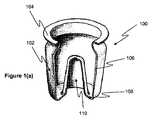
図1(a)は、エアロゾル発生装置で使用するためのカプセル100の等角破断図を示す。カプセルは、エアロゾル形成基体(図示せず)を含むシェル102を含み、シェルは、リップ部分104をシールするリッド(図示せず)でシールされている。 FIG. 1 (a) shows an isometric cutaway view of a
カプセル100のシェル102は、薄い壁の外部側壁106および薄い壁の基部108を含む。基部108は、その中央に位置する窪み110を含む。窪みは円錐台の形状であり、カプセルがエアロゾル発生装置内に挿入された時にヒーターを受けるように構成されている。 The
カプセルのシェルは、深絞りを使用して、少なくとも2段階で形成される。段階1は、適切なダイおよびパンチを使用したシェルおよび窪みの深絞りを含む。当然ながら、シェルおよび窪みが別の方法で2段階で形成されることを当業者は理解する。次に、シェルのリップがプロセスの段階2で形成される。製造プロセスは、図6を参照しながら下記にさらに詳しく説明されている。 The shell of the capsule is formed in at least two stages using deep drawing. Stage 1 includes deep drawing of the shell and recess using a suitable die and punch. Of course, those skilled in the art will appreciate that the shell and the recess are otherwise formed in two stages. A shell lip is then formed in stage 2 of the process. The manufacturing process is described in more detail below with reference to FIG.
図1(b)は、カプセル100の断面図を示す。カプセル100は、長軸方向の長さLcを持ち、またカプセルの基部は半径Rbを持つ。シェルの外部側壁106は厚さTsを持つ。シェルの基部108内の窪み110は、長軸方向の長さLrを持ち、また基部での窪み110の半径はRrである。FIG. 1B shows a cross-sectional view of the
カプセルの基部の半径(Rb)はおよそ4.5mmであり、またカプセルの長軸方向の長さはおよそ10.2mm(Lc)である。カプセルの壁の厚さ(Ts)はおよそ0.3mmである。The base radius (Rb ) of the capsule is approximately 4.5 mm, and the length in the longitudinal direction of the capsule is approximately 10.2 mm (Lc ). The capsule wall thickness (Ts ) is approximately 0.3 mm.
図2は、エアロゾル発生装置で使用するためのカプセル100の断面図を示す。見てわかる通り、また上述の通り、リッド200はリップ部分104にシールされる。リッドは、エポキシ接着剤、ヒートシール、超音波溶接、またはレーザー溶接などの接着剤を含めた、適切な任意の方法を使用してシールされうる。リッドがリップ部分にシールされる前に、カプセルのシェル102はエアロゾル形成基体202で充填される。およそ250mgのエアロゾル形成基体がシェル内に提供される。エアロゾル形成基体は、たばこ、およびエアロゾル形成剤などのニコチン含有材料を含む。エアロゾル形成剤は、ユーザーのために良好な食感を提供するグリセリンであるが、グリセリンは、その他のエアロゾル形成剤と比較して適切に小さいエアロゾル液滴直径を生むことも分かっている。 FIG. 2 shows a cross-sectional view of a
図3は、上述したカプセル100と併用するためのエアロゾル発生装置300の断面図を示す。エアロゾル発生装置は、再充電可能電池などの電源304と、制御回路306と、電気ヒーター308とを収容するように適合された外側ハウジング302を含む。ハウジング302は、カプセル100を受けるように構成された窪み309をさらに含む。電気ヒーターは、カプセルの窪みの円錐台形状に一致するよう構成された円錐台形状を持つヒーターハウジング310内に収容される。エアロゾル発生装置300は、エアロゾル発生装置ハウジング302の近位端に取付け可能なマウスピース312をさらに含む。マウスピースは、貫通部分314と、2つの気流コンジットである入口コンジット316および出口コンジット318を含む。 FIG. 3 shows a cross-sectional view of an
図4は、上述したエアロゾル発生装置300およびカプセル100を含む、エアロゾル発生システム400の断面図を示すが、同様な参照番号は同様な構成要素を参照する。カプセルは、ハウジングの窪み内に受けられ、またヒーターはカプセルの窪み内に挿入される。 FIG. 4 shows a cross-sectional view of an
使用時に、ユーザーは、カプセル100をエアロゾル発生装置300の窪みに挿入してから、マウスピース312をハウジング302に取り付ける。マウスピースを取り付けることにより、貫通部分314がカプセルのリッドを貫通し、空気吸込み口からカプセルを通して空気出口への気流経路を形成する。図4は、カプセル402に入る気流経路の部分、およびカプセルを出る気流経路404の部分を示す。ユーザーは次に、ボタン(図示せず)を押して装置を起動する。装置の起動においては、ヒーターに、電源304から制御電子回路306によって電力が供給される。カプセルの温度が約220℃〜約240℃の使用温度に達した時、インジケータ(図示せず)の手段によってユーザーは通知を受け、その後でユーザーはマウスピースを吸うことができる。ユーザーがマウスピースを吸う時、空気は空気吸込み口に入り、マウスピース内にあるコンジット316を通ってカプセル内に進み、蒸発したエアロゾル形成基体を混入してから、マウスピース内の出口コンジット318を経由してカプセルを出る。 In use, the user inserts the
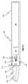
図5(a)は、上述のエアロゾル発生装置のための電気ヒーター308を示す。電気ヒーターは、その上にトラック(図示せず)としてプリントされたプラチナ、金または銀など、電気抵抗性のある材料を有する柔軟性のあるポリマー系の基体を含む。ヒーター308には、制御回路306を経由して電源304と接続するための電気接点502および504を含むタブ500が提供されている。 FIG. 5 (a) shows an
図5(b)は、エアロゾル発生装置300で使用される、円錐台形状に形成された電気ヒーター308を示す。ヒーターは、柔軟性のある基体を圧延することで円錐台形状に形成される。図5(c)に示す通り、形成されたヒーターは次にヒーターハウジング310に挿入され、ハウジングをエポキシ化合物506で充填してヒーターを所定位置に保持することでハウジング内に入れられる。 FIG. 5B shows an
上述の通り、カプセルのシェル102は、2段階のプロセスで製造しうるが、シェル102は次に、エアロゾル形成基体202で充填されてからリッド200でシールされ、カプセルを形成する。ここでプロセスについて、図6を参照しながら詳細に説明する。 As described above, the
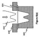
シェルを形成するプロセスの第一の段階を、図6(a)、6(b)および6(c)に示す。要求される形態のシェルを持つダイ600と、対応するパンチ602とが提供されている。実質的に円形の形状のブランク604が、クランプ606によってダイにスライドできるようにクランプ留めされる。クランプ606により、ブランク604は、パンチ602によってダイ600内に引き込まれた際に、ダイ600の上面に沿ってスライドできるようになる。当業者にとっては当然のことながら、このプロセスには、形成されたブランクのサイズを最終的に要求されるサイズに徐々に減少させる、複数のダイおよびパンチを持つ多数の中間的な段階が関与しうる。 The first stage of the process of forming the shell is shown in FIGS. 6 (a), 6 (b) and 6 (c). A die 600 having the required form of shell and a
第一の段階が完了すると、製造プロセスの第二の段階で、シェルのリップ104が形成され、リッドをシェルにシールできるようになる。図6(d)および6(e)は、プロセスのこの第二の段階を示す。2個組のダイ608および610は、部分的に形成されたブランク604上に進められ、リップ104のネックが部分的に形成される。形成プロセスを支援するために、2個組のダイ、または別の方法としてブランクは、2個組のダイがブランク上に進む際に長軸方向軸の周りを回転しうる。図6(e)では、リップ104を最終的に形成するさらなるダイが使用されることが示されている。ダイは、部分的に形成されたブランク上に進み、ブランク材料が曲げられてリップになる。ここでも、ダイ、または部分的に形成されたブランクは、形成プロセスを支援するために長軸方向軸の周りを回転させてもよい。 When the first stage is completed, the
ここで図6(f)は、形成されたシェル102が、スプレーガン614によってエアロゾル形成基体202で充填されているところを示す。図6(g)は、充填されたシェルを示す。 Here, FIG. 6 (f) shows that the formed
図6(h)および6(i)は、リッド200をシェル102にシールする最後のプロセスを示す。リッド200は、リッドホルダー616によってシェル102に向かって進められる。リッドホルダーは、当業者であれば理解する通り、真空ホルダーまたはその他任意の適切なホルダーでもよい。リッドは、接着剤またはその他任意の適切なシール手段を用いて提供されうる。最終的に、リッド200はシェル102にシールされる。この例で、リッドは、リッドに塗る前の接着剤を溶かすヒーター618によってシェルにヒートシールされる。 6 (h) and 6 (i) show the final process of sealing the
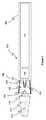
当業者であれば理解する通り、図3に示すエアロゾル発生装置は、本発明によるエアロゾル発生装置の一例に過ぎない。その他のこうした一例を図7に示す。図7に示したエアロゾル発生装置700は、図3に示したものと類似しており、類似した参照番号は類似した特徴を参照する。 As will be appreciated by those skilled in the art, the aerosol generator shown in FIG. 3 is merely an example of an aerosol generator according to the present invention. Another such example is shown in FIG. The
エアロゾル発生装置は、再充電可能電池などの電源304と、制御回路306と、内部電気ヒーター308と、外部電気ヒーター702を収容するように適合された外側ハウジング302を含む。ハウジング302は、カプセル100を受けるように構成された窪み309をさらに含む。内部電気ヒーター308は、カプセルの窪みの円錐台形状に一致するよう構成された円錐台形状を持つヒーターハウジング310内に収容される。外部ヒーター702には窪み309が提供される。エアロゾル発生装置300は、エアロゾル発生装置ハウジング302の近位端に取付け可能なマウスピース312をさらに含む。マウスピースは、貫通部分314と、2つの気流コンジットである入口コンジット316および出口コンジット318を含む。 The aerosol generator includes an
使用時に、エアロゾル発生装置700は、図4を参照しながら上述したエアロゾル発生装置300と同様な方法で動作する。ところが、制御回路306は、内部ヒーター308および外部ヒーター702の両方に電力を供給する。追加的な外部ヒーター702は、さらなる加熱をカプセルに提供し、例えば、初回吸煙までの時間をさらに短縮し、なおさらにヒーターからエアロゾル形成基体までの最大距離を短縮することにより、エアロゾル形成基体の熱伝達を向上させる。 In use, the
Claims (14)
Translated fromJapanese基部および前記基部から延びる少なくとも1つの側壁を備えたシェルであって、前記シェルが固体の構成要素を持ち、かつニコチン塩マトリクスおよびたばこのうち少なくとも1つを含む、エアロゾル形成基体を含むものと、
シールされたカプセルを形成するための前記少なくとも1つの側壁にシールされたリッドとを含み、
前記基部が、エアロゾル発生装置のヒーターを受けるために前記シェル内に前記カプセルの長軸方向軸に沿って延びる窪みを含む、カプセル。A capsule for an aerosol generator,
A shell having a base and at least one sidewall extending from the base, the shell having a solid component and comprising an aerosol-forming substrate comprising at least one of a nicotine salt matrix and tobacco;
A lid sealed to said at least one side wall to form a sealed capsule;
Capsule, wherein the base includes a recess extending along the longitudinal axis of the capsule in the shell for receiving a heater of an aerosol generator.
請求項1〜7のいずれか1項に記載のカプセルと、
エアロゾル発生装置であって、前記エアロゾル発生装置が、
電源と、
少なくとも1つのヒーターと、
前記カプセルを受けるための窪みと、
前記カプセルの前記リッドを貫通するための貫通要素を含むマウスピースとを含み、
前記少なくとも1つのヒーターが、前記カプセルの前記窪みに挿入可能であるように構成されているものとを備えた、エアロゾル発生システム。An aerosol generation system,
The capsule according to any one of claims 1 to 7,
An aerosol generator, wherein the aerosol generator is
Power supply,
At least one heater;
A recess for receiving the capsule;
A mouthpiece including a penetrating element for penetrating the lid of the capsule;
An aerosol generation system comprising: the at least one heater configured to be insertable into the depression of the capsule.
Applications Claiming Priority (3)
| Application Number | Priority Date | Filing Date | Title |
|---|---|---|---|
| EP13199892.4 | 2013-12-31 | ||
| EP13199892 | 2013-12-31 | ||
| PCT/EP2014/077920WO2015101479A1 (en) | 2013-12-31 | 2014-12-16 | An aerosol-generating device, and a capsule for use in an aerosol-generating device |
Publications (2)
| Publication Number | Publication Date |
|---|---|
| JP2017503499A JP2017503499A (en) | 2017-02-02 |
| JP6444418B2true JP6444418B2 (en) | 2018-12-26 |
Family
ID=49918486
Family Applications (1)
| Application Number | Title | Priority Date | Filing Date |
|---|---|---|---|
| JP2016544100AActiveJP6444418B2 (en) | 2013-12-31 | 2014-12-16 | Aerosol generator and capsule for use in aerosol generator |
Country Status (19)
| Country | Link |
|---|---|
| US (1) | US10206430B2 (en) |
| EP (1) | EP3089599B1 (en) |
| JP (1) | JP6444418B2 (en) |
| KR (1) | KR102376088B1 (en) |
| CN (1) | CN105828646B (en) |
| AU (1) | AU2014375382B2 (en) |
| BR (1) | BR112016012280B1 (en) |
| CA (1) | CA2928678A1 (en) |
| EA (1) | EA034534B1 (en) |
| ES (1) | ES2716093T3 (en) |
| IL (1) | IL245072B (en) |
| MX (1) | MX2016008657A (en) |
| MY (1) | MY179370A (en) |
| PH (1) | PH12016500648B1 (en) |
| PL (1) | PL3089599T3 (en) |
| SG (1) | SG11201605380WA (en) |
| UA (1) | UA118770C2 (en) |
| WO (1) | WO2015101479A1 (en) |
| ZA (1) | ZA201602405B (en) |
Families Citing this family (126)
| Publication number | Priority date | Publication date | Assignee | Title |
|---|---|---|---|---|
| US20160345631A1 (en) | 2005-07-19 | 2016-12-01 | James Monsees | Portable devices for generating an inhalable vapor |
| US10517530B2 (en) | 2012-08-28 | 2019-12-31 | Juul Labs, Inc. | Methods and devices for delivering and monitoring of tobacco, nicotine, or other substances |
| US10279934B2 (en) | 2013-03-15 | 2019-05-07 | Juul Labs, Inc. | Fillable vaporizer cartridge and method of filling |
| CN105263345A (en) | 2013-05-06 | 2016-01-20 | 派克斯实验公司 | Nicotine salt formulations for aerosol devices and methods thereof |
| CN105473012B (en) | 2013-06-14 | 2020-06-19 | 尤尔实验室有限公司 | Multiple heating elements with separate vaporizable materials in electronic vaporization equipment |
| US10039321B2 (en) | 2013-11-12 | 2018-08-07 | Vmr Products Llc | Vaporizer |
| KR20240070710A (en) | 2013-12-05 | 2024-05-21 | 쥴 랩스, 인크. | Nicotine liquid formulations for aerosol devices and methods thereof |
| US10076139B2 (en) | 2013-12-23 | 2018-09-18 | Juul Labs, Inc. | Vaporizer apparatus |
| US10058129B2 (en) | 2013-12-23 | 2018-08-28 | Juul Labs, Inc. | Vaporization device systems and methods |
| USD842536S1 (en) | 2016-07-28 | 2019-03-05 | Juul Labs, Inc. | Vaporizer cartridge |
| USD825102S1 (en) | 2016-07-28 | 2018-08-07 | Juul Labs, Inc. | Vaporizer device with cartridge |
| US20160366947A1 (en) | 2013-12-23 | 2016-12-22 | James Monsees | Vaporizer apparatus |
| US10159282B2 (en) | 2013-12-23 | 2018-12-25 | Juul Labs, Inc. | Cartridge for use with a vaporizer device |
| DE202014011260U1 (en) | 2013-12-23 | 2018-11-13 | Juul Labs Uk Holdco Limited | Systems for an evaporation device |
| WO2015175979A1 (en) | 2014-05-16 | 2015-11-19 | Pax Labs, Inc. | Systems and methods for aerosolizing a smokeable material |
| GB2527597B (en)* | 2014-06-27 | 2016-11-23 | Relco Induction Dev Ltd | Electronic Vapour Inhalers |
| US10058123B2 (en)* | 2014-07-11 | 2018-08-28 | R. J. Reynolds Tobacco Company | Heater for an aerosol delivery device and methods of formation thereof |
| TR201901447T4 (en)* | 2014-11-21 | 2019-02-21 | Philip Morris Products Sa | Smoking product containing a frictional flammable carbon heat source. |
| MX394125B (en) | 2014-12-05 | 2025-03-24 | Juul Labs Inc | CALIBRATED DOSE CONTROL |
| GB201505592D0 (en)* | 2015-03-31 | 2015-05-13 | British American Tobacco Co | Apparatus for heating smokable material |
| MX2017012644A (en) | 2015-04-07 | 2018-01-24 | Philip Morris Products Sa | Sachet of aerosol-forming substrate, method of manufacturing same, and aerosol-generating device for use with sachet. |
| GB201511349D0 (en) | 2015-06-29 | 2015-08-12 | Nicoventures Holdings Ltd | Electronic aerosol provision systems |
| GB201511361D0 (en) | 2015-06-29 | 2015-08-12 | Nicoventures Holdings Ltd | Electronic vapour provision system |
| MX2018001418A (en) | 2015-08-07 | 2018-04-13 | Philip Morris Products Sa | An aerosol-generating system with enhanced airflow management. |
| KR102659808B1 (en) | 2015-08-07 | 2024-04-23 | 필립모리스 프로덕츠 에스.에이. | Aerosol generation system with enhanced airflow management |
| RU2706924C2 (en) | 2015-08-14 | 2019-11-21 | Филип Моррис Продактс С.А. | Capsule in blister and container for aerosol generating system |
| GB201515087D0 (en) | 2015-08-25 | 2015-10-07 | Nicoventures Holdings Ltd | Electronic vapour provision system |
| US20170055574A1 (en)* | 2015-08-31 | 2017-03-02 | British American Tobacco (Investments) Limited | Cartridge for use with apparatus for heating smokable material |
| WO2017068096A1 (en) | 2015-10-22 | 2017-04-27 | Philip Morris Products S.A. | Aerosol-generating system and capsule for use in an aerosol-generating system |
| US12011049B2 (en) | 2015-10-22 | 2024-06-18 | Philip Morris Products S.A. | Aerosol generating article, aerosol-generating system and method for manufacturing an aerosol-generating article |
| CN113303514B (en)* | 2015-10-22 | 2024-11-12 | 菲利普莫里斯生产公司 | Aerosol Generating System |
| US20180317554A1 (en) | 2015-10-30 | 2018-11-08 | British American Tobacco (Investments) Limited | Article for use with apparatus for heating smokable material |
| US20170119051A1 (en) | 2015-10-30 | 2017-05-04 | British American Tobacco (Investments) Limited | Article for Use with Apparatus for Heating Smokable Material |
| US20170119050A1 (en) | 2015-10-30 | 2017-05-04 | British American Tobacco (Investments) Limited | Article for Use with Apparatus for Heating Smokable Material |
| DE102015121435B4 (en)* | 2015-11-10 | 2020-06-18 | AF Development Holding Ltd. | Hookah |
| GB201522368D0 (en)* | 2015-12-18 | 2016-02-03 | Jt Int Sa | An aerosol generating device |
| KR20180097533A (en)* | 2015-12-23 | 2018-08-31 | 필립모리스 프로덕츠 에스.에이. | Aerosol generating component for use in an aerosol generating article |
| EP3413960B1 (en) | 2016-02-11 | 2021-03-31 | Juul Labs, Inc. | Fillable vaporizer cartridge and method of filling |
| CO2018009342A2 (en) | 2016-02-11 | 2018-09-20 | Juul Labs Inc | Secure fixing cartridges for vaporizing devices |
| US10405582B2 (en) | 2016-03-10 | 2019-09-10 | Pax Labs, Inc. | Vaporization device with lip sensing |
| GB201605357D0 (en)* | 2016-03-30 | 2016-05-11 | British American Tobacco Co | Apparatus for heating aerosol generating material and a cartridge for the apparatus |
| US10334882B2 (en)* | 2016-04-13 | 2019-07-02 | Md&C Creative Masion Sa | Electronic cigarette |
| RU2731860C2 (en)* | 2016-05-31 | 2020-09-08 | Филип Моррис Продактс С.А. | Device for heat dissipation for aerosol generating system |
| US10918135B2 (en) | 2016-05-31 | 2021-02-16 | Altria Client Services Llc | Heat diffuser for an aerosol-generating system |
| MX2018014310A (en) | 2016-05-31 | 2019-02-25 | Philip Morris Products Sa | Aerosol-generating system comprising a heated aerosol-generating article. |
| US10660368B2 (en) | 2016-05-31 | 2020-05-26 | Altria Client Services Llc | Aerosol generating article with heat diffuser |
| MX2018014052A (en)* | 2016-05-31 | 2019-04-04 | Philip Morris Products Sa | Aerosol-generating device having a side cavity. |
| US10952472B2 (en) | 2016-05-31 | 2021-03-23 | Altria Client Services Llc | Heat diffuser for an aerosol-generating system |
| CA3014136A1 (en) | 2016-05-31 | 2017-12-07 | Philip Morris Products S.A. | Aerosol generating article with heat diffuser |
| USD849996S1 (en) | 2016-06-16 | 2019-05-28 | Pax Labs, Inc. | Vaporizer cartridge |
| USD848057S1 (en) | 2016-06-23 | 2019-05-07 | Pax Labs, Inc. | Lid for a vaporizer |
| USD836541S1 (en) | 2016-06-23 | 2018-12-25 | Pax Labs, Inc. | Charging device |
| USD851830S1 (en) | 2016-06-23 | 2019-06-18 | Pax Labs, Inc. | Combined vaporizer tamp and pick tool |
| RU2020135859A (en) | 2016-06-29 | 2020-12-04 | Никовенчерс Трейдинг Лимитед | DEVICE FOR HEATING SMOKING MATERIAL |
| AU2017289114B2 (en) | 2016-06-29 | 2020-04-30 | Nicoventures Trading Limited | Apparatus for heating smokable material |
| US10791760B2 (en)* | 2016-07-29 | 2020-10-06 | Altria Client Services Llc | Aerosol-generating system including a cartridge containing a gel |
| US10772355B2 (en)* | 2016-07-29 | 2020-09-15 | Altria Client Services Llc | Aerosol-generating system including a heated gel container |
| CN109414056A (en)* | 2016-07-29 | 2019-03-01 | 菲利普莫里斯生产公司 | Aerosol generating system including cartridge containing gel |
| CN109475189A (en)* | 2016-07-29 | 2019-03-15 | 菲利普莫里斯生产公司 | Aerosol generation system including heated gel container |
| GB2553136B (en) | 2016-08-25 | 2020-09-16 | Nerudia Ltd | Device and system |
| US11660403B2 (en) | 2016-09-22 | 2023-05-30 | Juul Labs, Inc. | Leak-resistant vaporizer device |
| CN106418724A (en)* | 2016-10-28 | 2017-02-22 | 郭洪礼 | Electronic smoking apparatus |
| DE102016120786A1 (en)* | 2016-11-01 | 2018-05-03 | Hauni Maschinenbau Gmbh | Capsule for insertion into a head of a hookah, machine of the tobacco processing industry and method for producing such a capsule |
| US11045615B2 (en)* | 2016-12-19 | 2021-06-29 | Altria Client Services Llc | Vapor-generating systems |
| WO2018114441A1 (en)* | 2016-12-19 | 2018-06-28 | Philip Morris Products S.A. | An aerosol-generating system comprising multiple aerosol-forming substrates and a piercing element |
| EP4585081A2 (en)* | 2016-12-30 | 2025-07-16 | JT International SA | Aerosol generating system |
| CN115381137A (en) | 2017-03-17 | 2022-11-25 | 瑞恩·丹尼尔·塞尔比 | Closed Bottom Vaporizer Pods |
| GB2561867B (en) | 2017-04-25 | 2021-04-07 | Nerudia Ltd | Aerosol delivery system |
| JP7128215B2 (en)* | 2017-06-09 | 2022-08-30 | フィリップ・モーリス・プロダクツ・ソシエテ・アノニム | Adaptable aerosol generation system |
| JP6878684B2 (en)* | 2017-08-09 | 2021-06-02 | フィリップ・モーリス・プロダクツ・ソシエテ・アノニム | Aerosol generator with removable and insertable heating compartment |
| CN108569469A (en)* | 2017-09-04 | 2018-09-25 | 赫斯提亚深圳生物科技有限公司 | Aerosol generates product, its seal assembly and manufacturing method |
| CN108567171A (en)* | 2017-09-04 | 2018-09-25 | 赫斯提亚深圳生物科技有限公司 | Apparatus for aerosol creation and system |
| USD887632S1 (en) | 2017-09-14 | 2020-06-16 | Pax Labs, Inc. | Vaporizer cartridge |
| MY203861A (en) | 2017-09-15 | 2024-07-22 | Nicoventures Trading Ltd | Apparatus for heating smokable material |
| US11103656B2 (en)* | 2017-10-05 | 2021-08-31 | Derek Domenici | Inhalation device |
| CN111107757B (en)* | 2017-10-06 | 2023-10-31 | 菲利普莫里斯生产公司 | Hookah device with aerosol condensation |
| JP2019076077A (en)* | 2017-10-23 | 2019-05-23 | 株式会社 東亜産業 | Manufacturing method of filling material for electronic tobacco cartridge using non-tobacco plant |
| KR102014154B1 (en)* | 2017-11-03 | 2019-08-27 | 신종수 | Electronic Cigarette Using Fumigation |
| RU2737812C1 (en)* | 2017-12-06 | 2020-12-03 | Джапан Тобакко Инк. | Cartridge of aerosol inhaler, aerosol inhaler and metal heater of aerosol inhaler |
| GB201721766D0 (en) | 2017-12-22 | 2018-02-07 | British American Tobacco Investments Ltd | Electronic aerosol provision system |
| GB2569966A (en)* | 2018-01-04 | 2019-07-10 | William John McLaughlin David | A two-part aerosol production system |
| WO2019162507A1 (en)* | 2018-02-26 | 2019-08-29 | Nerudia Limited | A substitute smoking consumable |
| TWI664922B (en)* | 2018-04-30 | 2019-07-11 | 黃庭輝 | Heating device |
| IL278305B2 (en)* | 2018-05-02 | 2025-04-01 | Philip Morris Products Sa | Shisha cartridge |
| JP7544603B2 (en) | 2018-06-28 | 2024-09-03 | フィリップ・モーリス・プロダクツ・ソシエテ・アノニム | Cartridge for an aerosol generating system containing a nicotine source including a liquid nicotine formulation |
| CN110859322A (en)* | 2018-08-08 | 2020-03-06 | 北京航天雷特机电工程有限公司 | Cigarette bullet and electron cigarette |
| CN110916251A (en)* | 2018-09-04 | 2020-03-27 | 上海新型烟草制品研究院有限公司 | Heat-not-burn aerosol generation system, product and its covering member |
| CN209031260U (en)* | 2018-09-21 | 2019-06-28 | 深圳麦克韦尔股份有限公司 | Smoking set and its heating element |
| JP7526170B2 (en)* | 2018-10-12 | 2024-07-31 | ジェイティー インターナショナル エスエイ | Aerosol generating device and heating chamber therefor |
| EP3863446A1 (en)* | 2018-10-12 | 2021-08-18 | JT International SA | Aerosol generation device and heating chamber therefor |
| EA202190953A1 (en)* | 2018-10-12 | 2021-07-22 | ДжейТи ИНТЕРНЭШНЛ С.А. | AEROSOL GENERATING DEVICE AND HEATING CHAMBER FOR IT |
| JP7267408B2 (en) | 2018-10-12 | 2023-05-01 | ジェイティー インターナショナル エス.エイ. | Aerosol generator and heating chamber therefor |
| PT3636084T (en)* | 2018-10-12 | 2022-01-11 | Jt Int Sa | Aerosol generation device, and heating chamber therefor |
| US20200128880A1 (en)* | 2018-10-30 | 2020-04-30 | R.J. Reynolds Tobacco Company | Smoking article cartridge |
| PL3895561T3 (en)* | 2018-12-10 | 2025-02-10 | Japan Tobacco Inc. | NON-COMBUSTION HEATING SMOKING DEVICE |
| JP7315766B2 (en)* | 2018-12-10 | 2023-07-26 | 日本たばこ産業株式会社 | Non-combustion heating smoking device |
| GB201900627D0 (en)* | 2019-01-16 | 2019-03-06 | British American Tobacco Investments Ltd | Tobacco constituent releasing components, methods of making the components and articles comprising the components |
| CN109619697A (en)* | 2019-01-28 | 2019-04-16 | 深圳市卓力能电子有限公司 | Atomization core and preparation method thereof, aerosol generating device |
| GB201901204D0 (en)* | 2019-01-29 | 2019-03-20 | British American Tobacco Investments Ltd | Method and apparatus for manufacturing a consumable unit for an inhalation device, and a consumable unit for an inhalation device |
| EP3937681A4 (en)* | 2019-03-11 | 2023-03-22 | Selby, Ryan Daniel | IMPROVED SMOKING ARTICLE |
| GB201903249D0 (en)* | 2019-03-11 | 2019-04-24 | Nicoventures Trading Ltd | Aerosol provision device |
| EP3711545A1 (en)* | 2019-03-22 | 2020-09-23 | Nerudia Limited | Heating apparatus for smoking substitute system |
| KR20210151197A (en)* | 2019-04-18 | 2021-12-13 | 니뽄 다바코 산교 가부시키가이샤 | heated tobacco |
| CN113710108A (en)* | 2019-04-18 | 2021-11-26 | 日本烟草产业株式会社 | Heating type cigarette |
| DE102019117379A1 (en)* | 2019-06-27 | 2020-12-31 | Hauni Maschinenbau Gmbh | Inhaler and replaceable fluid reservoir for an inhaler |
| EA202190997A1 (en) | 2019-08-08 | 2021-07-21 | ДжейТи ИНТЕРНЭШНЛ С.А. | AEROSOL GENERATING DEVICE AND HEATING CHAMBER FOR IT |
| EP4025089A1 (en)* | 2019-09-06 | 2022-07-13 | JT International SA | Heating chamber |
| EP4069007B1 (en)* | 2019-12-02 | 2024-02-07 | Philip Morris Products S.A. | Shisha device with trough |
| WO2021151530A1 (en)* | 2020-01-30 | 2021-08-05 | Philip Morris Products S.A. | Multi-channel and reversed airflow mouthpiece for an aerosol- generating article comprising activatable element |
| US11882872B2 (en) | 2020-04-02 | 2024-01-30 | Altria Client Services Llc | Capsules, heat-not-burn (HNB) aerosol-generating devices, and methods of generating an aerosol |
| KR20230016616A (en)* | 2020-05-28 | 2023-02-02 | 제이티 인터내셔널 소시에떼 아노님 | Conical heating elements for electronic aerosol delivery systems |
| CA3170424A1 (en) | 2020-05-28 | 2021-12-02 | Claude Zominy | Aerosol generating device element |
| EP4156997B1 (en) | 2020-05-28 | 2025-02-19 | JT International SA | Aerosol generating system |
| EP4164431A1 (en)* | 2020-06-12 | 2023-04-19 | JT International SA | Consumable container, aerosol generation device and refillable system thereof, and method using the system |
| GB202011955D0 (en)* | 2020-07-31 | 2020-09-16 | Nicoventures Trading Ltd | Articles for use in aerosol provision system |
| KR102512072B1 (en)* | 2020-10-16 | 2023-03-20 | 주식회사 케이티앤지 | Aerosol generating article and aerosol generating device for heating the same |
| CN114845585A (en)* | 2020-11-16 | 2022-08-02 | 日本烟草产业株式会社 | Cigarette cartridge and method for manufacturing cigarette cartridge |
| KR20220067528A (en)* | 2020-11-16 | 2022-05-24 | 니뽄 다바코 산교 가부시키가이샤 | Cartridges and methods of manufacturing cartridges |
| KR20220067530A (en)* | 2020-11-16 | 2022-05-24 | 니뽄 다바코 산교 가부시키가이샤 | Cartridges and methods of manufacturing cartridges |
| JP7240531B2 (en)* | 2020-11-16 | 2023-03-15 | 日本たばこ産業株式会社 | Cartridge and cartridge manufacturing method |
| US12213517B2 (en)* | 2021-01-13 | 2025-02-04 | Sobota HnB Technologies LLC | Vaporizer for smoking cigarettes with individual heater |
| GB202108772D0 (en)* | 2021-06-18 | 2021-08-04 | Nicoventures Trading Ltd | Article for use in a non-combustible aerosol provision system |
| WO2023007673A1 (en)* | 2021-07-29 | 2023-02-02 | 日本たばこ産業株式会社 | Cartridge, and body part for non-combustion-type flavor inhaler |
| US11832642B2 (en)* | 2021-09-28 | 2023-12-05 | Johns Family Irrevocable Trust | Pipe and cartridge for a smokable media |
| KR20250094690A (en)* | 2022-10-27 | 2025-06-25 | 필립모리스 프로덕츠 에스.에이. | Aerosol-generating articles containing capsules |
| GB2632427A (en)* | 2023-08-07 | 2025-02-12 | Martin Lomas Peter | Aerosolizing system with replaceable capsule |
Family Cites Families (35)
| Publication number | Priority date | Publication date | Assignee | Title |
|---|---|---|---|---|
| US4692590A (en)* | 1984-10-09 | 1987-09-08 | Donald Spector | Aroma-generating automobile cigarette lighter |
| US6059659A (en) | 1996-06-07 | 2000-05-09 | Las Vegas Gaming, Inc. | Roulette table having progressive jackpots |
| DE69724559T2 (en)* | 1996-06-17 | 2004-07-15 | Japan Tobacco Inc. | FLAVORED ARTICLE |
| DE19847968A1 (en)* | 1998-10-17 | 2000-04-20 | Boehringer Ingelheim Pharma | Separate storage of an active material and a solvent comprises a closure cap and a container, with a chamber attached to the unit. |
| FR2844775B1 (en)* | 2002-09-20 | 2006-02-10 | Valois Sas | DEVICE FOR DISPENSING FLUID PRODUCT |
| US9675109B2 (en) | 2005-07-19 | 2017-06-13 | J. T. International Sa | Method and system for vaporization of a substance |
| US8042550B2 (en)* | 2006-11-02 | 2011-10-25 | Vladimir Nikolaevich Urtsev | Smoke-simulating pipe |
| CA2963423C (en)* | 2007-03-30 | 2020-07-28 | Philip Morris Products S.A. | Device and method for delivery of a medicament |
| US8991402B2 (en)* | 2007-12-18 | 2015-03-31 | Pax Labs, Inc. | Aerosol devices and methods for inhaling a substance and uses thereof |
| CN100594809C (en)* | 2008-02-29 | 2010-03-24 | 修运强 | Electronic simulation cigarette and atomized liquid thereof |
| AT507631B1 (en)* | 2008-11-26 | 2012-05-15 | Haas Rouven Mag | DEVICE FOR INTAKING POWDER OR GRANULATE MATERIAL AND CAPSULE THEREFOR |
| CN201379072Y (en)* | 2009-02-11 | 2010-01-13 | 韩力 | An improved atomized electronic cigarette |
| DK2456329T3 (en)* | 2009-07-22 | 2013-07-15 | Philip Morris Prod | Smoke-free cigarette replacement product |
| CN101822420B (en)* | 2010-04-22 | 2012-06-27 | 修运强 | Combined type multifunctional electronic simulated cigarette |
| US9259035B2 (en)* | 2010-05-15 | 2016-02-16 | R. J. Reynolds Tobacco Company | Solderless personal vaporizing inhaler |
| US8528569B1 (en)* | 2011-06-28 | 2013-09-10 | Kyle D. Newton | Electronic cigarette with liquid reservoir |
| CN102266125B (en) | 2011-07-28 | 2013-01-09 | 易侧位 | Health care type traditional Chinese medicine electronic cigarette for quitting smoking |
| US9078473B2 (en)* | 2011-08-09 | 2015-07-14 | R.J. Reynolds Tobacco Company | Smoking articles and use thereof for yielding inhalation materials |
| KR102177660B1 (en)* | 2011-08-16 | 2020-11-12 | 쥴 랩스, 인크. | Low temperature electronic vaporization device and methods |
| KR200456814Y1 (en)* | 2011-09-21 | 2011-11-21 | (주)잔티아시아 | Electronic cigarette with prefabricated combustion |
| CN102389167B (en)* | 2011-09-28 | 2013-05-29 | 卓尔悦(常州)电子科技有限公司 | Replaceable general atomizing head |
| US9498588B2 (en)* | 2011-12-14 | 2016-11-22 | Atmos Nation, LLC | Portable pen sized electric herb vaporizer with ceramic heating chamber |
| KR101184758B1 (en)* | 2012-01-13 | 2012-09-19 | 이영인 | Cartridge of electric cigarette for preventing leakage |
| DE102012100831B3 (en) | 2012-02-01 | 2013-02-14 | SNOKE GmbH & Co. KG | Electric cigarette |
| US9101729B2 (en)* | 2012-06-05 | 2015-08-11 | Huizou Kimree Technology Co., Ltd., Shenzhen Branch | Electronic cigarette and inhaling shell thereof |
| US20140041655A1 (en)* | 2012-08-11 | 2014-02-13 | Grenco Science, Inc | Portable Vaporizer |
| CN103202538A (en) | 2013-04-24 | 2013-07-17 | 上海烟草集团有限责任公司 | Cigarette not combusting under heating |
| CN203860456U (en) | 2013-05-02 | 2014-10-08 | Jt国际公司 | Plug and capsule for vaporizable material |
| CN103932401B (en)* | 2013-09-29 | 2015-09-30 | 深圳麦克韦尔股份有限公司 | Electronic cigarette |
| US9445630B1 (en)* | 2013-10-24 | 2016-09-20 | Jigar Modi | Pre-packed tobacco insert device |
| DE202014001718U1 (en)* | 2014-02-27 | 2015-05-28 | Xeo Holding GmbH | smoking device |
| AU2015252165B2 (en)* | 2014-04-30 | 2019-01-31 | Philip Morris Products S.A. | A container having a heater for an aerosol-generating device, and aerosol-generating device |
| CA2920949A1 (en)* | 2015-02-17 | 2016-08-17 | Mark Krietzman | Zoned vaporizer |
| KR102659808B1 (en)* | 2015-08-07 | 2024-04-23 | 필립모리스 프로덕츠 에스.에이. | Aerosol generation system with enhanced airflow management |
| US10165796B2 (en)* | 2015-12-18 | 2019-01-01 | Naji Gebara | Hookah system |
- 2014
- 2014-12-16CACA2928678Apatent/CA2928678A1/ennot_activeAbandoned
- 2014-12-16KRKR1020167015021Apatent/KR102376088B1/enactiveActive
- 2014-12-16AUAU2014375382Apatent/AU2014375382B2/ennot_activeCeased
- 2014-12-16WOPCT/EP2014/077920patent/WO2015101479A1/enactiveApplication Filing
- 2014-12-16EPEP14815321.6Apatent/EP3089599B1/enactiveActive
- 2014-12-16SGSG11201605380WApatent/SG11201605380WA/enunknown
- 2014-12-16ESES14815321Tpatent/ES2716093T3/enactiveActive
- 2014-12-16MYMYPI2016701579Apatent/MY179370A/enunknown
- 2014-12-16UAUAA201606990Apatent/UA118770C2/enunknown
- 2014-12-16USUS15/108,967patent/US10206430B2/enactiveActive
- 2014-12-16PLPL14815321Tpatent/PL3089599T3/enunknown
- 2014-12-16MXMX2016008657Apatent/MX2016008657A/enunknown
- 2014-12-16CNCN201480067075.XApatent/CN105828646B/enactiveActive
- 2014-12-16EAEA201691324Apatent/EA034534B1/ennot_activeIP Right Cessation
- 2014-12-16JPJP2016544100Apatent/JP6444418B2/enactiveActive
- 2014-12-16BRBR112016012280-1Apatent/BR112016012280B1/enactiveIP Right Grant
- 2016
- 2016-04-08ZAZA2016/02405Apatent/ZA201602405B/enunknown
- 2016-04-08PHPH12016500648Apatent/PH12016500648B1/enunknown
- 2016-04-12ILIL24507216Apatent/IL245072B/ennot_activeIP Right Cessation
Also Published As
| Publication number | Publication date |
|---|---|
| CN105828646A (en) | 2016-08-03 |
| EA201691324A1 (en) | 2016-10-31 |
| WO2015101479A1 (en) | 2015-07-09 |
| SG11201605380WA (en) | 2016-07-28 |
| EP3089599A1 (en) | 2016-11-09 |
| UA118770C2 (en) | 2019-03-11 |
| AU2014375382B2 (en) | 2019-01-17 |
| EA034534B1 (en) | 2020-02-18 |
| EP3089599B1 (en) | 2019-02-13 |
| PL3089599T3 (en) | 2019-06-28 |
| US10206430B2 (en) | 2019-02-19 |
| MY179370A (en) | 2020-11-05 |
| IL245072A0 (en) | 2016-06-30 |
| ZA201602405B (en) | 2017-07-26 |
| KR102376088B1 (en) | 2022-03-18 |
| PH12016500648A1 (en) | 2016-05-30 |
| PH12016500648B1 (en) | 2016-05-30 |
| ES2716093T3 (en) | 2019-06-10 |
| CA2928678A1 (en) | 2015-07-09 |
| AU2014375382A1 (en) | 2016-05-05 |
| KR20160105391A (en) | 2016-09-06 |
| MX2016008657A (en) | 2017-02-13 |
| IL245072B (en) | 2019-10-31 |
| HK1225580A1 (en) | 2017-09-15 |
| BR112016012280A2 (en) | 2017-08-08 |
| JP2017503499A (en) | 2017-02-02 |
| BR112016012280B1 (en) | 2021-12-14 |
| US20160324215A1 (en) | 2016-11-10 |
| CN105828646B (en) | 2019-07-26 |
Similar Documents
| Publication | Publication Date | Title |
|---|---|---|
| JP6444418B2 (en) | Aerosol generator and capsule for use in aerosol generator | |
| JP6615114B2 (en) | Container with heater for aerosol generator and aerosol generator | |
| JP6666850B2 (en) | Container having heater for aerosol generator, and aerosol generator | |
| TWI738701B (en) | Aerosol-generating device with sealed compartment and aerosol-generating system | |
| JP2025143323A (en) | Aerosol generating device and heating chamber therefor | |
| JP2022502065A (en) | Aerosol generator and heating chamber for it | |
| JP2022504417A (en) | Aerosol generator and heating chamber for it | |
| KR20180111799A (en) | An aerosol generator having a plurality of power supply units | |
| KR20220023450A (en) | Covection heater and aerosol-generating apparatus including the same | |
| US20220378107A1 (en) | Electronic aerosol provision system and method | |
| HK1225580B (en) | An aerosol-generating device, and a capsule for use in an aerosol-generating device | |
| CN218483782U (en) | An aerosol generating device and system |
Legal Events
| Date | Code | Title | Description |
|---|---|---|---|
| A521 | Request for written amendment filed | Free format text:JAPANESE INTERMEDIATE CODE: A523 Effective date:20160704 | |
| A621 | Written request for application examination | Free format text:JAPANESE INTERMEDIATE CODE: A621 Effective date:20171206 | |
| TRDD | Decision of grant or rejection written | ||
| A01 | Written decision to grant a patent or to grant a registration (utility model) | Free format text:JAPANESE INTERMEDIATE CODE: A01 Effective date:20181101 | |
| A61 | First payment of annual fees (during grant procedure) | Free format text:JAPANESE INTERMEDIATE CODE: A61 Effective date:20181127 | |
| R150 | Certificate of patent or registration of utility model | Ref document number:6444418 Country of ref document:JP Free format text:JAPANESE INTERMEDIATE CODE: R150 | |
| R250 | Receipt of annual fees | Free format text:JAPANESE INTERMEDIATE CODE: R250 | |
| R250 | Receipt of annual fees | Free format text:JAPANESE INTERMEDIATE CODE: R250 | |
| R250 | Receipt of annual fees | Free format text:JAPANESE INTERMEDIATE CODE: R250 | |
| R250 | Receipt of annual fees | Free format text:JAPANESE INTERMEDIATE CODE: R250 |