JP6443993B2 - Method for knitting a knit component with an integral knit tongue - Google Patents
Method for knitting a knit component with an integral knit tongueDownload PDFInfo
- Publication number
- JP6443993B2 JP6443993B2JP2015560294AJP2015560294AJP6443993B2JP 6443993 B2JP6443993 B2JP 6443993B2JP 2015560294 AJP2015560294 AJP 2015560294AJP 2015560294 AJP2015560294 AJP 2015560294AJP 6443993 B2JP6443993 B2JP 6443993B2
- Authority
- JP
- Japan
- Prior art keywords
- knit
- knitting
- integral
- component
- tongue
- Prior art date
- Legal status (The legal status is an assumption and is not a legal conclusion. Google has not performed a legal analysis and makes no representation as to the accuracy of the status listed.)
- Active
Links
Images


Classifications
- D—TEXTILES; PAPER
- D04—BRAIDING; LACE-MAKING; KNITTING; TRIMMINGS; NON-WOVEN FABRICS
- D04B—KNITTING
- D04B7/00—Flat-bed knitting machines with independently-movable needles
- D04B7/04—Flat-bed knitting machines with independently-movable needles with two sets of needles
- D—TEXTILES; PAPER
- D04—BRAIDING; LACE-MAKING; KNITTING; TRIMMINGS; NON-WOVEN FABRICS
- D04B—KNITTING
- D04B1/00—Weft knitting processes for the production of fabrics or articles not dependent on the use of particular machines; Fabrics or articles defined by such processes
- D04B1/22—Weft knitting processes for the production of fabrics or articles not dependent on the use of particular machines; Fabrics or articles defined by such processes specially adapted for knitting goods of particular configuration
- D04B1/24—Weft knitting processes for the production of fabrics or articles not dependent on the use of particular machines; Fabrics or articles defined by such processes specially adapted for knitting goods of particular configuration wearing apparel
- A—HUMAN NECESSITIES
- A43—FOOTWEAR
- A43B—CHARACTERISTIC FEATURES OF FOOTWEAR; PARTS OF FOOTWEAR
- A43B1/00—Footwear characterised by the material
- A43B1/02—Footwear characterised by the material made of fibres or fabrics made therefrom
- A43B1/04—Footwear characterised by the material made of fibres or fabrics made therefrom braided, knotted, knitted or crocheted
- A—HUMAN NECESSITIES
- A43—FOOTWEAR
- A43B—CHARACTERISTIC FEATURES OF FOOTWEAR; PARTS OF FOOTWEAR
- A43B23/00—Uppers; Boot legs; Stiffeners; Other single parts of footwear
- A43B23/02—Uppers; Boot legs
- A43B23/0205—Uppers; Boot legs characterised by the material
- A—HUMAN NECESSITIES
- A43—FOOTWEAR
- A43B—CHARACTERISTIC FEATURES OF FOOTWEAR; PARTS OF FOOTWEAR
- A43B23/00—Uppers; Boot legs; Stiffeners; Other single parts of footwear
- A43B23/02—Uppers; Boot legs
- A43B23/0245—Uppers; Boot legs characterised by the constructive form
- A—HUMAN NECESSITIES
- A43—FOOTWEAR
- A43B—CHARACTERISTIC FEATURES OF FOOTWEAR; PARTS OF FOOTWEAR
- A43B23/00—Uppers; Boot legs; Stiffeners; Other single parts of footwear
- A43B23/02—Uppers; Boot legs
- A43B23/0245—Uppers; Boot legs characterised by the constructive form
- A43B23/0265—Uppers; Boot legs characterised by the constructive form having different properties in different directions
- A—HUMAN NECESSITIES
- A43—FOOTWEAR
- A43B—CHARACTERISTIC FEATURES OF FOOTWEAR; PARTS OF FOOTWEAR
- A43B23/00—Uppers; Boot legs; Stiffeners; Other single parts of footwear
- A43B23/26—Tongues for shoes
- A—HUMAN NECESSITIES
- A43—FOOTWEAR
- A43C—FASTENINGS OR ATTACHMENTS OF FOOTWEAR; LACES IN GENERAL
- A43C5/00—Eyelets
- D—TEXTILES; PAPER
- D04—BRAIDING; LACE-MAKING; KNITTING; TRIMMINGS; NON-WOVEN FABRICS
- D04B—KNITTING
- D04B1/00—Weft knitting processes for the production of fabrics or articles not dependent on the use of particular machines; Fabrics or articles defined by such processes
- D04B1/10—Patterned fabrics or articles
- D04B1/102—Patterned fabrics or articles with stitch pattern
- D04B1/104—Openwork fabric, e.g. pelerine fabrics
- D—TEXTILES; PAPER
- D04—BRAIDING; LACE-MAKING; KNITTING; TRIMMINGS; NON-WOVEN FABRICS
- D04B—KNITTING
- D04B1/00—Weft knitting processes for the production of fabrics or articles not dependent on the use of particular machines; Fabrics or articles defined by such processes
- D04B1/10—Patterned fabrics or articles
- D04B1/12—Patterned fabrics or articles characterised by thread material
- D04B1/123—Patterned fabrics or articles characterised by thread material with laid-in unlooped yarn, e.g. fleece fabrics
- D—TEXTILES; PAPER
- D04—BRAIDING; LACE-MAKING; KNITTING; TRIMMINGS; NON-WOVEN FABRICS
- D04B—KNITTING
- D04B1/00—Weft knitting processes for the production of fabrics or articles not dependent on the use of particular machines; Fabrics or articles defined by such processes
- D04B1/10—Patterned fabrics or articles
- D04B1/12—Patterned fabrics or articles characterised by thread material
- D04B1/126—Patterned fabrics or articles characterised by thread material with colour pattern, e.g. intarsia fabrics
- D—TEXTILES; PAPER
- D04—BRAIDING; LACE-MAKING; KNITTING; TRIMMINGS; NON-WOVEN FABRICS
- D04B—KNITTING
- D04B1/00—Weft knitting processes for the production of fabrics or articles not dependent on the use of particular machines; Fabrics or articles defined by such processes
- D04B1/22—Weft knitting processes for the production of fabrics or articles not dependent on the use of particular machines; Fabrics or articles defined by such processes specially adapted for knitting goods of particular configuration
- D—TEXTILES; PAPER
- D04—BRAIDING; LACE-MAKING; KNITTING; TRIMMINGS; NON-WOVEN FABRICS
- D04B—KNITTING
- D04B15/00—Details of, or auxiliary devices incorporated in, weft knitting machines, restricted to machines of this kind
- D04B15/38—Devices for supplying, feeding, or guiding threads to needles
- D04B15/54—Thread guides
- D04B15/56—Thread guides for flat-bed knitting machines
- D—TEXTILES; PAPER
- D04—BRAIDING; LACE-MAKING; KNITTING; TRIMMINGS; NON-WOVEN FABRICS
- D04B—KNITTING
- D04B37/00—Auxiliary apparatus or devices for use with knitting machines
- D04B37/02—Auxiliary apparatus or devices for use with knitting machines with weft knitting machines
- D—TEXTILES; PAPER
- D04—BRAIDING; LACE-MAKING; KNITTING; TRIMMINGS; NON-WOVEN FABRICS
- D04B—KNITTING
- D04B7/00—Flat-bed knitting machines with independently-movable needles
- D04B7/24—Flat-bed knitting machines with independently-movable needles for producing patterned fabrics
- D—TEXTILES; PAPER
- D04—BRAIDING; LACE-MAKING; KNITTING; TRIMMINGS; NON-WOVEN FABRICS
- D04B—KNITTING
- D04B7/00—Flat-bed knitting machines with independently-movable needles
- D04B7/24—Flat-bed knitting machines with independently-movable needles for producing patterned fabrics
- D04B7/28—Flat-bed knitting machines with independently-movable needles for producing patterned fabrics with stitch patterns
- D—TEXTILES; PAPER
- D04—BRAIDING; LACE-MAKING; KNITTING; TRIMMINGS; NON-WOVEN FABRICS
- D04B—KNITTING
- D04B19/00—Unravelling knitted fabrics
- D—TEXTILES; PAPER
- D10—INDEXING SCHEME ASSOCIATED WITH SUBLASSES OF SECTION D, RELATING TO TEXTILES
- D10B—INDEXING SCHEME ASSOCIATED WITH SUBLASSES OF SECTION D, RELATING TO TEXTILES
- D10B2401/00—Physical properties
- D10B2401/04—Heat-responsive characteristics
- D10B2401/041—Heat-responsive characteristics thermoplastic; thermosetting
- D—TEXTILES; PAPER
- D10—INDEXING SCHEME ASSOCIATED WITH SUBLASSES OF SECTION D, RELATING TO TEXTILES
- D10B—INDEXING SCHEME ASSOCIATED WITH SUBLASSES OF SECTION D, RELATING TO TEXTILES
- D10B2403/00—Details of fabric structure established in the fabric forming process
- D10B2403/01—Surface features
- D10B2403/011—Dissimilar front and back faces
- D10B2403/0113—One surface including hollow piping or integrated straps, e.g. for inserts or mountings
- D—TEXTILES; PAPER
- D10—INDEXING SCHEME ASSOCIATED WITH SUBLASSES OF SECTION D, RELATING TO TEXTILES
- D10B—INDEXING SCHEME ASSOCIATED WITH SUBLASSES OF SECTION D, RELATING TO TEXTILES
- D10B2403/00—Details of fabric structure established in the fabric forming process
- D10B2403/01—Surface features
- D10B2403/011—Dissimilar front and back faces
- D10B2403/0114—Dissimilar front and back faces with one or more yarns appearing predominantly on one face, e.g. plated or paralleled yarns
- D—TEXTILES; PAPER
- D10—INDEXING SCHEME ASSOCIATED WITH SUBLASSES OF SECTION D, RELATING TO TEXTILES
- D10B—INDEXING SCHEME ASSOCIATED WITH SUBLASSES OF SECTION D, RELATING TO TEXTILES
- D10B2403/00—Details of fabric structure established in the fabric forming process
- D10B2403/02—Cross-sectional features
- D10B2403/023—Fabric with at least two, predominantly unlinked, knitted or woven plies interlaced with each other at spaced locations or linked to a common internal co-extensive yarn system
- D—TEXTILES; PAPER
- D10—INDEXING SCHEME ASSOCIATED WITH SUBLASSES OF SECTION D, RELATING TO TEXTILES
- D10B—INDEXING SCHEME ASSOCIATED WITH SUBLASSES OF SECTION D, RELATING TO TEXTILES
- D10B2403/00—Details of fabric structure established in the fabric forming process
- D10B2403/02—Cross-sectional features
- D10B2403/024—Fabric incorporating additional compounds
- D10B2403/0241—Fabric incorporating additional compounds enhancing mechanical properties
- D—TEXTILES; PAPER
- D10—INDEXING SCHEME ASSOCIATED WITH SUBLASSES OF SECTION D, RELATING TO TEXTILES
- D10B—INDEXING SCHEME ASSOCIATED WITH SUBLASSES OF SECTION D, RELATING TO TEXTILES
- D10B2403/00—Details of fabric structure established in the fabric forming process
- D10B2403/03—Shape features
- D10B2403/032—Flat fabric of variable width, e.g. including one or more fashioned panels
- D—TEXTILES; PAPER
- D10—INDEXING SCHEME ASSOCIATED WITH SUBLASSES OF SECTION D, RELATING TO TEXTILES
- D10B—INDEXING SCHEME ASSOCIATED WITH SUBLASSES OF SECTION D, RELATING TO TEXTILES
- D10B2501/00—Wearing apparel
- D10B2501/04—Outerwear; Protective garments
- D10B2501/043—Footwear
Landscapes
- Engineering & Computer Science (AREA)
- Textile Engineering (AREA)
- Chemical & Material Sciences (AREA)
- Materials Engineering (AREA)
- Footwear And Its Accessory, Manufacturing Method And Apparatuses (AREA)
- Knitting Of Fabric (AREA)
- Knitting Machines (AREA)
Description
Translated fromJapanese本発明は、一般に履物製品の製造方法に関し、特に履物製品の一体型ニットベロを有するニット構成要素の編みプロセスに関する。 The present invention relates generally to a method of manufacturing a footwear product, and more particularly to a knitting process of a knitted component having an integral knit tongue of the footwear product.
従来の履物製品は一般に、アッパーおよびソール構造という2つの主要な要素を含んでいる。アッパーは、ソール構造に固定されて、足を快適にかつ安定して受け入れるために、履物の内部に空洞を形成する。ソール構造は、それによってアッパーと地面との間に位置するように、アッパーの下側区域に固定されている。例えば、運動用の履物では、ソール構造は、ミッドソールとアウトソールとを含んでいてもよい。ミッドソールは、地面の反力を弱めて、歩くとき、走るとき、および他の歩行活動中に足および脚にかかる応力を低減するポリマー発泡材料を含んでいてもよい。さらに、ミッドソールは、力をさらに弱め、安定性を高め、または足の動きに影響を与える液体充填チャンバ、プレート、モデレータ、または他の要素を含んでいてもよい。アウトソールは、ミッドソールの下面に固定されて、ゴムなど耐久性のある耐摩耗性材料で形成されたソール構造の地面係止部を提供する。ソール構造は、履物の快適性を高めるために、空洞内に配置され、足の下面に近接する中敷きも含んでいてもよい。 Conventional footwear products generally include two main elements: an upper and a sole structure. The upper is secured to the sole structure and forms a cavity within the footwear to receive the foot comfortably and stably. The sole structure is secured to the lower area of the upper so that it lies between the upper and the ground. For example, in athletic footwear, the sole structure may include a midsole and an outsole. The midsole may include a polymeric foam material that reduces ground reaction forces and reduces stress on the feet and legs when walking, running, and during other walking activities. In addition, the midsole may include liquid-filled chambers, plates, moderators, or other elements that further reduce force, increase stability, or affect foot movement. The outsole is fixed to the lower surface of the midsole and provides a ground locking portion of a sole structure formed of a durable wear-resistant material such as rubber. The sole structure may also include an insole disposed within the cavity and proximate to the underside of the foot to enhance footwear comfort.
アッパーは大略的に、足の甲およびつま先区域にわたり、足の内側側部および外側側部に沿って、足の下および足のかかと区域の周りに延びている。バスケットボール用履物およびブーツなどいくつかの履物製品では、アッパーは上方に、足首の周りに延びて、足首に支持または保護を与えてもよい。アッパーの内部の空洞へのアクセスは一般に、履物のかかと区域にある足首開口部によって提供される。アッパーの履き心地を調整するために、しばしば締めひもシステムがアッパーに組み込まれ、それによりアッパー内の空洞に足を入れ、足を抜くことが可能になる。締めひもシステムにより、着用者がアッパーの特定の寸法、特に周長を調節して、さまざまな寸法の足を収容することもできる。くわえて、アッパーは、締めひもシステムの下に延びて、履物の調節可能性を高めるベロを含んでいてもよく、アッパーは、かかとの動きを制限するために、ヒールカウンタを組み込んでいてもよい。 The upper generally extends across the instep and toe area, along the medial and lateral sides of the foot, below the foot and around the heel area of the foot. In some footwear products, such as basketball footwear and boots, the upper may extend upward and around the ankle to provide support or protection to the ankle. Access to the cavity inside the upper is generally provided by an ankle opening in the heel area of the footwear. In order to adjust the comfort of the upper, a lace system is often incorporated into the upper, which allows the foot to enter and withdraw the foot into the cavity in the upper. The lacing system also allows the wearer to accommodate specific dimensions of the upper, particularly the circumference, to accommodate various sized feet. In addition, the upper may include a tongue that extends under the lacing system to increase the adjustability of the footwear, and the upper may incorporate a heel counter to limit heel movement. .
さまざまな材料要素(例えば、織物、ポリマー発泡体、ポリマーシート、革、合成皮革)が、従来、アッパーを製造する際に利用されている。例えば、運動用の履物では、アッパーは、それぞれが様々な接合材料要素を含む複数の層を有していてもよい。例として、材料要素は、耐伸縮性、耐摩耗性、柔軟性、通気性、圧縮性、快適性および速乾性をアッパーの異なる区域に付与するように選択してもよい。アッパーの異なる区域に異なる特性を付与するために、材料要素を所望の形状に切断してから、通常は、縫製または接着剤で互いに接合することが多い。また、材料要素は、同じ区域に多数の特性を付与するために層状構成で接合されることが多い。アッパーに組み込まれる材料要素の数および種類が増えるにつれ、材料要素の輸送、保管、切断および接合に関連する時間および費用も増加することがある。切断および縫製プロセスから出る廃材も、アッパーに組み込まれる材料要素の数および種類が増えるにつれて、さらに多く蓄積する。さらに、アッパーの材料要素の数が多くなるほど、種類および数が少ない材料要素から形成されているアッパーよりもリサイクルが難しくなることがある。そのため、アッパーに利用する材料要素の数を減らすことにより、アッパーの製造効率およびリサイクル性を高めながら、廃棄物を少なくすることができる。 Various material elements (eg, woven fabrics, polymer foams, polymer sheets, leather, synthetic leather) are conventionally utilized in manufacturing uppers. For example, in athletic footwear, the upper may have multiple layers, each containing various bonding material elements. As an example, the material elements may be selected to impart stretch resistance, abrasion resistance, flexibility, breathability, compressibility, comfort and quick-drying to different areas of the upper. In order to impart different properties to different areas of the upper, the material elements are often cut into the desired shape and then usually joined together by sewing or adhesive. Also, material elements are often joined in a layered configuration to impart multiple properties to the same area. As the number and type of material elements incorporated into the upper increases, the time and costs associated with transporting, storing, cutting and joining the material elements may increase. More waste material from the cutting and sewing process accumulates as the number and type of material elements incorporated into the upper increases. In addition, the greater the number of material elements in the upper, the more difficult it may be to recycle than an upper made from fewer and fewer types of material elements. Therefore, by reducing the number of material elements used for the upper, waste can be reduced while improving the manufacturing efficiency and recyclability of the upper.
そのため、一体型ニットベロを有するニット構成要素を組み込んだ履物製品のニーズが存在する。 Therefore, there is a need for footwear products that incorporate knit components having an integral knit tongue.
履物製品のさまざまな構成は、アッパーとアッパーに固定されているソール構造とを有してもよい。アッパーおよび一体型ニットベロを含むニット構成要素が履物製品に組み込まれている。アッパーおよび一体型ニットベロはワンピースニット要素として形成されている。ニット要素はアッパーの外側面の一部およびアッパーの反対側の内側面を画成し、内側面が足を受け入れるための空洞を画成している。一体型ニットベロはワンピースニット要素としてアッパーとの一体ニット構造で形成されて、アッパーのスロート区域を通って延びている。一体型ニットベロは、締めひもシステムの締めひも開口部を提供する隆起要素を組み込んでいる。 Various configurations of footwear products may have an upper and a sole structure secured to the upper. A knit component including an upper and an integral knit tongue is incorporated into the footwear product. The upper and integral knit tongue are formed as one-piece knit elements. The knitted element defines a portion of the upper outer surface and an inner surface opposite the upper, the inner surface defining a cavity for receiving a foot. The integral knit tongue is formed as a one-piece knit element with an integral knit structure with the upper and extends through the throat section of the upper. The integral knit tongue incorporates a raised element that provides a lace opening for the lacing system.
ある態様において、本発明は、履物製品のニット構成要素を製造する方法であって、編み機を用いて、ニット構成要素の外側面およびニット構成要素の反対側の内側面のうちの少なくとも一方の一部を含むアッパーを画成するニット構成要素の部分を編むステップと、編み機を用いて、アッパーとの一体ニット構造を成し、ニット構成要素のスロート区域を通って延びている一体型ニットベロを編むステップとを備えており、前記一体型ニットベロは、編み機を用いて、スロート区域の前方部分を、ならびに少なくとも前方部分からアッパーの足首開口部まで延びているニット構成要素のスロート区域の外側側部および内側側部の一部を沿って編むことにより接合されている方法を提供する。 In one aspect, the present invention is a method of manufacturing a knit component of an article of footwear, the method using a knitting machine to at least one of an outer surface of the knit component and an inner surface opposite the knit component. Knitting the part of the knit component defining the upper including the part, and using a knitting machine, forming an integral knit structure with the upper and knitting the integral knit tongue extending through the throat area of the knit component The integrated knit bevel using a knitting machine to extend the front portion of the throat area and at least the outer side of the throat area of the knitted component extending from the front portion to the ankle opening of the upper and A method of joining by knitting along a portion of the inner side is provided.
別の態様によると、本発明は、履物製品のニット構成要素を製造する方法であって、編み機の第1フィーダーを用いて、ニット構成要素の外側面およびニット構成要素の反対側の内側面のうちの少なくとも一方の一部を含むアッパーを画成するニット構成要素の第1部分を編むステップと、編み機の第2フィーダーを用いて、アッパーを画成しているニット構成要素の第2部分を編むステップと、編み機の第1フィーダーおよび第2フィーダーのうちの少なくとも一方を用いて、アッパーとの一体ニット構造を成し、ニット構成要素のスロート区域を通って延びている一体型ニットベロを編むステップとを備えており、前記一体型ニットベロは、編み機を用いて、スロート区域の前方部分を、ならびに少なくともアッパーの前方部分から足首開口部まで延びているニット構成要素のスロート区域の外側側部および内側側部の一部を沿って編むことにより接合されている方法を提供する。 According to another aspect, the present invention is a method of manufacturing a knitted component of an article of footwear using a first feeder of a knitting machine on the outer surface of the knitted component and the inner surface opposite the knitted component. Knitting a first portion of a knit component defining an upper including a portion of at least one of the two, and using a second feeder of the knitting machine, a second portion of the knit component defining the upper A step of knitting, and using at least one of the first feeder and the second feeder of the knitting machine to form an integral knit structure with the upper and knitting the integral knit tongue extending through the throat area of the knit component The integrated knit bellows using a knitting machine to move the front part of the throat area as well as at least the front part of the upper A method that has been joined by knitting along a portion of the outer side and inner side of the throat area of the knitted component which extends to the mouth.
別の側面において、本発明は、履物製品のニット構成要素を製造する方法であって、編み機の第1フィーダーを用いて、ニット構成要素の外側面およびニット構成要素の反対側の内側面のうちの少なくとも一方の一部を含むアッパーを画成しているニット構成要素の第1部分を編むステップと、編み機の第2フィーダーを用いて、アッパーを画成しているニット構成要素の第2部分を編むステップと、編み機の第3フィーダーを用いて、アッパーとの一体ニット構造を成し、ニット構成要素のスロート区域を通って延びている一体型ニットベロを編むステップとを備えており、一体型ニットベロは、編み機を用いて、スロート区域の前方部分を、ならびに少なくともアッパーの前方部分から足首開口部まで延びているニット構成要素のスロート区域の外側側部および内側側部の一部を沿って編むことにより接合されている方法を提供する。 In another aspect, the present invention is a method of manufacturing a knitted component of an article of footwear, wherein a first feeder of a knitting machine is used to make an outer surface of the knitted component and an inner surface opposite to the knitted component. Knitting a first portion of a knit component defining an upper including a portion of at least one of the first and a second portion of the knit component defining an upper using a second feeder of the knitting machine Using a third feeder of the knitting machine, forming an integral knit structure with the upper, and knitting an integral knit tongue extending through the throat area of the knit component. A knitvelo uses a knitting machine to throw a knit component that extends from the front part of the throat area as well as at least from the front part of the upper to the ankle opening. A method that has been joined by knitting along a portion of the outer side and inner side zone.
本発明の他のシステム、方法、特徴および利点は、以下の図面および詳細な説明を検討すると、当業者には明らかであり、または明らかとなる。当該すべての追加システム、方法、特徴および利点は本明細書および本発明の概要内に含まれており、本発明の範囲内であり、以下の請求項によって保護されることが意図される。 Other systems, methods, features and advantages of the present invention will be or will be apparent to those of ordinary skill in the art upon review of the following drawings and detailed description. All such additional systems, methods, features and advantages are included herein and within the scope of the invention, are within the scope of the invention, and are intended to be protected by the following claims.
本発明は以下の図面および説明を参照するとより一層理解できる。図の中の構成要素は必ずしも縮尺どおりではなく、本発明の原理を図示するにあたり強調を施している。また、図中、同じ参照番号は様々な図面を通して対応する部品を表す。 The invention can be better understood with reference to the following drawings and description. The components in the figures are not necessarily to scale, emphasis instead being placed upon illustrating the principles of the invention. Also, in the figures, like reference numerals designate corresponding parts throughout the various views.
以下の説明および添付の図面は、ニット構成要素およびニット構成要素の製造に関するさまざまな概念を開示する。ニット構成要素はさまざまな製品において利用してもよいが、一実施例としてニット構成要素の1つを組み込んでいる履物製品を以下に開示する。履物の他に、ニット構成要素は他の種類の衣料品(例、シャツ、ズボン、靴下、上着、下着)、運動用品(例、ゴルフバッグ、野球およびフットボール用のグローブ、サッカーボールの規制構造体)、入れ物(例、バックパック、バッグ)、および家具の装飾用品(例、椅子、ソファ、カーシート)に利用してもよい。ニット構成要素はベッドカバーリング(例、シーツ、毛布)、テーブルカバーリング、タオル、旗、テント、帆およびパラシュートに利用してもよい。ニット構成要素は、自動車および航空宇宙産業用の構造物、フィルタ材料、医療用の布(例、包帯、綿棒、移植組織片)、堤防を補強するためのジオテキスタイル、作物を保護するためのアグロテキスタイル、ならびに熱および放射から保護または絶縁する工業用衣料品を含め、産業用の技術的テキスタイルとして利用してもよい。したがって、本明細書で開示するニット構成要素および他の概念は、個人用および産業用の両方の目的のためのさまざまな製品に組み込んでもよい。 The following description and the accompanying drawings disclose various concepts relating to the knit component and the manufacture of the knit component. Although the knitted component may be utilized in a variety of products, an footwear product incorporating one of the knitted components is disclosed below as an example. In addition to footwear, knitted components are other types of clothing (eg, shirts, pants, socks, outerwear, underwear), sports equipment (eg, golf bags, baseball and football gloves, regulatory structures for soccer balls) Body), containers (eg, backpacks, bags), and furniture decorations (eg, chairs, sofas, car seats). Knit components may be used for bed coverings (eg, sheets, blankets), table coverings, towels, flags, tents, sails and parachutes. Knit components include structures for automotive and aerospace industries, filter materials, medical fabrics (eg bandages, cotton swabs, grafts), geotextiles to reinforce dikes, agrotextiles to protect crops And industrial textiles including industrial clothing that protects or insulates from heat and radiation. Accordingly, the knitted components and other concepts disclosed herein may be incorporated into various products for both personal and industrial purposes.
履物の構成
図1から図15は、本明細書で説明および図示する原理によるさまざまな履物構成を示す。特に、図1から図4Bは、アッパーおよび一体型ニットベロを含むニット構成要素を組み込んでいる履物製品の例示的な実施形態を示す。Footwear Configurations FIGS. 1-15 illustrate various footwear configurations according to the principles described and illustrated herein. In particular, FIGS. 1-4B illustrate an exemplary embodiment of an article of footwear incorporating a knit component that includes an upper and an integral knit tongue.
図1から図4Bは、単に履物100ともいう履物製品100の例示的な実施形態を示す。いくつかの実施形態において、履物製品100はソール構造110とアッパー120とを含んでもよい。履物100はランニングに適した一般的な構成を有するように図示されているが、履物100に関連する概念は、たとえば野球靴、バスケットボールシューズ、サイクリングシューズ、フットボールシューズ、テニスシューズ、サッカーシューズ、トレーニングシューズ、ウォーキングシューズ、およびハイキングブーツを含め、さまざまな他の運動用の履物の種類にも適用してもよい。この概念は、ドレスシューズ、ローファー、サンダルおよび作業靴を含め、一般に非運動用と考えられる履物の種類にも適用してもよい。したがって、履物100に関して開示する概念は、多様な履物の種類に適用される。 FIGS. 1-4B illustrate an exemplary embodiment of an article of
参照のために、図1、図2および図3に図示するように、履物100は足先領域101と中足領域102とかかと領域103との大略的に3つの領域に分割してもよい。足先領域101は、大略的に、つま先、および中足骨と指骨とを接続する関節に対応する履物100の部分を含んでいる。中足領域102は、大略的に、足のアーチ区域に対応する履物100の部分を含んでいる。かかと領域103は、大略的に、踵骨を含めて足の後部に対応している。履物100は外側側部104および内側側部105も含んでおり、足先領域101、中足領域102およびかかと領域103のそれぞれを通って延びており、履物100の両側に対応する。より具体的には、外側側部104は足の外側部位に対応し(つまり、反対の足から遠ざかる方を向く面)、内側側部105は足の内側部位に対応する(つまり、反対の足の方を向く面)。足先領域101、中足領域102およびかかと領域103ならびに外側側部104、内側側部105は履物100の厳密な区域を区切ることを意図していない。むしろ、足先領域101、中足領域102およびかかと領域103ならびに外側側部104、内側側部105は、以下の説明の助けになるように、履物100の大略的な区域を表すことを意図している。履物100に加えて、足先領域101、中足領域102およびかかと領域103ならびに外側側部104、内側側部105はソール構造110、アッパー120およびそれらの個々の要素に適用してもよい。 For reference, as shown in FIGS. 1, 2 and 3, the
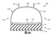
例示的な実施形態では、ソール構造110はアッパー120に固定されていて、履物100を履いたときに足と地面との間に延びる。いくつかの実施形態では、ソール構造110の主要な要素はミッドソール111、アウトソール112、および中敷き113である(図4Aおよび図4Bに示す)。ミッドソール111はアッパー120の下面に固定されて、歩いているとき、走っているとき、または他の歩行活動中に足と地面との間で圧縮されると、地面の反力を弱める(つまり、クッション材となる)圧縮可能なポリマー発泡体要素(例、ポリウレタンまたはエチルビニルアセテート発泡体)から形成してもよい。他の実施形態では、ミッドソール111は、さらに力を弱め、安定性を高め、もしくは足の動きに影響を与えるプレート、モデレータ、液体充填チャンバ、ラスティング要素、もしくはモーションコントロール部材を組み込んでもよく、またはミッドソール111は主に液体充填チャンバから形成してもよい。アウトソール112はミッドソール111の下面に固定されて、牽引力を付与するように織られた耐摩耗性のゴム材料から形成してもよい。中敷き113はアッパー120内に配置されていて、足の下面の下に延びて履物100の快適性を高めるように位置付けられている。ソール構造110のこの構成はアッパー120と接続して使用してもよいソール構造の一実施例を提供しているが、ソール構造110のさまざまな他の従来の構成または従来にない構成も利用してもよい。したがって、他の実施形態では、ソール構造110またはアッパー120とともに利用されるソール構造の特徴は変わってもよい。 In the exemplary embodiment,
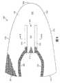
いくつかの実施形態では、アッパー120は、ソール構造110に対して足を受け入れて固定するための空洞を履物100内に画定する。空洞は足を収容するような形状にされており、足の外側側部に沿い、足の内側側部に沿い、足の上、かかとの周り、さらに足の下に延びている。空洞へのアクセスは、少なくともかかと領域103に配置されている足首開口部121により提供される。いくつかの実施形態では、かかと領域103の足首開口部121から足の甲に対応する区域を越えて足先領域101に隣接する区域までスロート区域123が延びている。例示的な実施形態では、一体型ニットベロ140は、アッパー120との一体ニット構造で形成されており、外側側部104と内側側部105との間にアッパー120のスロート区域123を通って延びている。 In some embodiments, the upper 120 defines a cavity in the
締めひも122が一体型ニットベロ140の隆起要素142にあるさまざまな締めひも開口部143を通って延びており、着用者がアッパー120の寸法を調整してさまざまな足のプロポーションを収容できるようにする。さらに具体的には、締めひも122は着用者が足の周りでアッパー120を締め付けることができるようにし、また締めひも122は着用者が空洞からの(つまり、足首開口部121を通して)足の出し入れを容易にするために、アッパー120を緩めることができるようにする。さらに、アッパー120の一体型ニットベロ140は締めひも122の下に延びて履物100の快適性を高める。さらなる構成では、アッパー120は、(a)かかと領域103に安定性を高めるヒールカウンタ、(b)足先領域101に耐摩耗性材料で形成されているつま先ガード、ならびに(c)ロゴ、商標、および注意書きや材料情報を記載した札などの追加要素を含んでいてもよい。 A
従来の履物のアッパーの多くは、たとえば縫製または接着により接合されている多数の材料要素(例、織物、ポリマー発泡体、ポリマーシート、革、合成皮革)から形成されている。対して、アッパー120の大部分はニット構成要素130から形成されており、足先領域101、中足領域102およびかかと領域103のそれぞれを通って、外側側部104および内側側部105の両方に沿い、足先領域101の上、さらにかかと領域103の周りに延びている。くわえて、ニット構成要素130はアッパー120の外側面および反対側の内側面の両方の部分を形成している。このように、ニット構成要素130はアッパー120内に空洞の少なくとも一部を画成している。いくつかの構成では、ニット構成要素130は足の下にも延びていてもよい。しかし、図4Aおよび図4Bを参照すると、ストローベル式中敷き125がニット構成要素130およびミッドソール111の上面に固定されており、それにより中敷き113の下に延びているアッパー120の一部を形成している。 Many conventional footwear uppers are formed from a number of material elements (e.g., fabrics, polymer foam, polymer sheets, leather, synthetic leather) that are joined together, for example, by sewing or gluing. In contrast, most of the upper 120 is formed from a
いくつかの実施形態では、ニット構成要素130は、一体ニット構造で形成されているアッパー120および一体型ニットベロ140を含んでもよい。アッパー120および一体型ニットベロ140を含むニット構成要素は、比較的少数の材料要素を用いて形成されていてもよい。前記背景技術のセクションで述べたように、アッパーの形成に使用する材料要素の数を少なくすると廃棄物を少なくすることができるとともに、アッパーの製造効率およびリサイクル性も高まる。従来のアッパーのベロおよびカラーなどの他の部分は、後で合わせて接合する多数の個別の材料要素から形成されていることが多い。しかし、以下詳細に述べるように、一体型ニットベロ要素は主に編みプロセス(ステッチ&ターン法ではなく)から形成してもよく、廃棄物を減らすとともに、製造効率およびリサイクル性を高める。さらに、一体型ニットベロ要素140の構造は組み込んでいる縫い目または他の切れ目の数を少なくしてもよいので、履物100の全体的な快適性が向上する。 In some embodiments, the
編みプロセス中に一体型ニットベロ140を構成すること、およびアッパー120を有する一体ニット構造のさらなる利点は、より効率的な製造および共通の特性を与えることを含む。より具体的には、編みプロセス中にニット構成要素130をより多く形成し、しばしば人の手で行われるさまざまな工程(例、個別のベロの作製、ベロの固定)を省くことによって、製造効率を高めてもよい。一体型ニットベロ140およびアッパー120は、同じヤーン(もしくは同じ種類のヤーン)または同様なニット構造から形成する場合、共通の特性をもつ。たとえば、一体型ニットベロ140およびアッパー120の両方に同じヤーンを使用すると、同様な耐久性、強度、伸縮性、耐摩耗性、生物分解性、熱特性および疎水性を与える。物性に加えて、一体型ニットベロ140およびアッパー120の両方に同じヤーンを使用して、色、光沢および手触りなど、共通の美的特性または触覚的特性を与えてもよい。一体型ニットベロ140およびアッパー120の両方に同じニット構造を使用して、共通の物性および美的特性を与えてもよい。これらの利点は、一体型ニットベロ140の少なくとも一部およびアッパー120の少なくとも一部を共通のヤーン(もしくは共通の種類のヤーン)から、または共通のニット構造を用いて形成する場合も存在する。 Configuring the
ニット構成要素の構成
図5から図15は、図1から図4Bの例示的な実施形態と同様に、履物製品に組み込んでもよいニット構成要素のさまざまな実施形態を示している。図5から図15に図示するニット構成要素は、履物100の残りの部分とは別に描かれている。ただし、本明細書で説明するニット構成要素の実施形態のそれぞれは、前記説明した履物100の要素と組み合わせて、ニット構成要素を組み込んでいる履物製品を形成してもよいことは理解されるべきである。Knit Component Configuration FIGS. 5-15 illustrate various embodiments of knit components that may be incorporated into an article of footwear, similar to the exemplary embodiment of FIGS. 1-4. The knit component illustrated in FIGS. 5-15 is depicted separately from the rest of the
ここで図5を参照すると、第1ニット構成要素500の例示的な実施形態が平面図で示されている。第1ニット構成要素500は、前記説明したニット構成要素130と実質的に同じであってもよい。いくつかの実施形態では、第1ニット構成要素500は、アッパー502を画定している第1部分と、一体型ニットベロ512を画定している第2部分とを含む。例示的な実施形態では、第1ニット構成要素500は、一体ニット構造から形成されているアッパー502および一体型ニットベロ要素512を組み込んでいる。本明細書および請求項で使用するニット構成要素(例、第1ニット構成要素500、または本明細書で説明する他のニット構成要素)とは、編みプロセスでワンピース要素として形成されるとき、「一体ニット構造」から形成されていると定義される。すなわち、編みプロセスは、大幅な追加の製造工程またはプロセスの必要なく、第1ニット構成要素500のさまざまな特徴および構造を実質的に形成する。一体ニット構造を使用して、構造もしくは要素が共通の少なくとも1つのコースを含むように(つまり、共通のヤーンを共有する)、および/または構造もしくは要素のそれぞれの間に実質的に連続するコースを含むように接合されるヤーンまたは他のニット材料の1つ以上のコースを含む構造もしくは要素(アッパー502および一体型ニットベロ512を含む)を有するニット構成要素を形成してもよい。この構成により、一体ニット構造のワンピース要素が提供される。 Referring now to FIG. 5, an exemplary embodiment of the
第1ニット構成要素500の部分は編みプロセスの後に互いに接合してもよいが(例、第1ニット構成要素500の縁部を互いに接合する)、第1ニット構成要素500は、ワンピースニット要素として形成されているため、依然として一体ニット構造から形成されたままである。また、第1ニット構成要素500は、編みプロセスの後に他の要素(例、締めひも、ロゴ、商標、注意書きや材料情報や構造的要素を記載した札)を追加しても、依然として一体ニット構造から形成されたままである。 While the portions of the first
例示的な実施形態では、第1ニット構成要素500の主要な要素は、アッパー502および一体型ニットベロ512を形成しているニット要素である。ニット要素は、さまざまなコースおよびウェールを画成する複数の互いにかみ合うループを形成するように操作される(例、編み機を用いて)少なくとも1本のヤーンから形成されていてもよい。すなわち、第1ニット構成要素500を形成しているニット要素はニット布地の構造を有する。以下に説明する実施形態を含めてニット構成要素の他の実施形態は、ニット要素と少なくとも1つの伸張要素とを含んでもよい。 In the exemplary embodiment, the primary elements of the
第1ニット構成要素500は、外周および内周により輪郭が描かれる略U字形の構成を有する。この実施形態では、外周は前周縁部503と、外側周縁部504と、内側周縁部505と、外側かかと縁部506および内側かかと縁部507を含む1対のかかと縁部とを含む。第1ニット構成要素500の内周は、外側内縁部508と、内側内縁部509と、前内縁部510とを含む。履物100を含む履物製品に組み込まれるとき、前周縁部503、外側周縁部504、内側周縁部505、ならびに外側かかと縁部506および内側かかと縁部507の少なくとも一部は、ミッドソールの上面に置かれて、ストローベル式中敷きに接合される(例、前述したミッドソール111およびストローベル式中敷き125)。さらに、外側かかと縁部506および内側かかと縁部507は互いに接合されて、かかと領域に垂直に延びている。履物のいくつかの構成では、材料要素は外側かかと縁部506と内側かかと縁部507との間の縫い目を覆って、縫い目を補強するとともに、履物の美的な魅力を高めてもよい。外側内縁部508、内側内縁部509および前内縁部510は合わせて、前述した足首開口部121を含む足首開口部を形成して、一体型ニットベロ512が配置されているスロート区域520まで前方に延びている。くわえて、いくつかの実施形態では、スロート区域520は締めひもと締めひもを受ける締めひも開口部とをさらに含んでもよい。 The
くわえて、第1ニット構成要素500は第1の表面530と反対側の第2の表面532とを有してもよい。第1の表面530はアッパー502の外側面の一部を形成するのに対し、第2の表面532はアッパー502の内側面の一部を形成するので、アッパー502内に空洞の少なくとも一部を画成する。 In addition, the first
さまざまな実施形態において、ニット構成要素はアッパーの個別の区域に異なる特性を付与するさまざまな種類のヤーンを組み込んでもよい。たとえば、第1ニット構成要素500のある区域は第1特性セットを付与する第1種のヤーンから形成してもよく、第1ニット構成要素500の別の区域は第2特性セットを付与する第2種のヤーンから形成してもよい。この構成で、第1ニット構成要素500の異なる区域に特有のヤーンを選択することによって、アッパー502全体で特性を変えてもよい。 In various embodiments, the knitted component may incorporate various types of yarns that impart different properties to individual areas of the upper. For example, one area of the first
ある特定の種類のヤーンがニット構成要素の一区域に付与することになる特性は、ヤーン内のさまざまなフィラメントおよびファイバを形成している材料に部分的に依存する。たとえば、綿は柔らかな手触り、自然な美観、および生物分解性を提供する。エラステインおよび伸縮性ポリエステルは、それぞれ相当の伸縮性および復元力を提供し、伸縮性ポリマーはリサイクル性も提供する。レーヨンは光沢に優れ、吸湿性を提供する。ウールも断熱性および生物分解性に加えて、高い吸湿性を提供する。ナイロンは耐久性があり耐擦過性材料で、比較的強度が高い。ポリエステルは疎水性の材料で、比較的高い耐久性も提供する。 The properties that a particular type of yarn will impart to a section of the knitted component depends in part on the materials forming the various filaments and fibers within the yarn. For example, cotton provides a soft hand, natural aesthetics, and biodegradability. Elastane and stretchable polyester provide considerable stretch and resilience, respectively, and stretchable polymer also provides recyclability. Rayon is excellent in gloss and provides hygroscopicity. Wool also provides high hygroscopicity in addition to thermal insulation and biodegradability. Nylon is a durable, scratch-resistant material that is relatively strong. Polyester is a hydrophobic material and also provides a relatively high durability.
材料に加えて、ニット構成要素のために選択されるヤーンの他の側面がアッパーの特性に影響することもある。たとえば、第1ニット構成要素500を形成するヤーンは単繊維ヤーンまたは多繊維ヤーンであってもよい。ヤーンはそれぞれ異なる材料から形成される個別のフィラメントを含んでいてもよい。くわえて、ヤーンは、鞘芯構成を有するフィラメントまたは異なる材料から形成される2種類のフィラメントを半分ずつ用いた複合ヤーンなど、それぞれ2つ以上の異なる材料から形成されるフィラメントを含んでいてもよい。撚りおよび捲縮の程度を異ならせること、ならびにデニールを異ならせることでもアッパー502の特性に影響を与えてもよい。したがって、ヤーンおよびヤーンを形成する材料およびヤーンの他の側面の両方を、アッパー502の個別区域にさまざまな特性を付与するために選択してもよい。 In addition to the material, other aspects of the yarn selected for the knitted component can affect the properties of the upper. For example, the yarn forming the first
いくつかの実施形態では、一体型ニットベロ512は第1ニット構成要素500のスロート区域520の中央に配置してもよく、かかと領域の足首開口部から足の甲に対応する区域を越えて、足先領域に隣接する区域まで延びているとともに、第1ニット構成要素の外側側部と内側側部との間に延びていてもよい。例示的な実施形態では、一体型ニットベロ512は、第1ニット構成要素500のスロート区域520の前方部分に、アッパー502との一体ニット構造で形成されている。すなわち、一体型ニットベロ512は、スロート区域520の前方部分に、一体型ニットベロ512とアッパー502とが共通の少なくとも1つのコースを含み、および/または一体型ニットベロ512とアッパー502との間に実質的に連続しているコースを含むように、スロート区域520の前方部分でアッパー502に編み込むことにより接合されている。 In some embodiments, the
例示的な実施形態では、一体型ニットベロ512は、第1ニット構成要素500のスロート区域520の長さに沿って延びている一体型ニットベロ512の両側に沿って、アッパー502との一体ニット構造でさらに形成されていてもよい。したがって、一体型ニットベロ512は、一体型ニットベロ512およびアッパー502が共通の少なくとも1つのコースを含むように、および/またはスロート区域520に沿って延びている両側に沿って一体型ニットベロ512とアッパー502との間に実質的に連続するコースを含むように、スロート区域520の外側側部および内側側部のそれぞれに沿ってアッパー502に編み込むことにより接合される。 In the exemplary embodiment, the
いくつかの実施形態では、一体型ニットベロ512はスロート区域520の両側に設けられて、一体型ニットベロ512の長さに沿って延びている隆起要素を含んでもよい。隆起要素は、編みプロセスにより、アッパー502の第1の表面530から離れて外方に延びている一体型ニットベロ512のフラップまたは突き出し部分になるように形成されている一体型ニットベロ512の一部であってもよい。図5に図示するように、一体型ニットベロ512は外側隆起要素514と内側隆起要素515とを含む。例示的な実施形態では、外側隆起要素514および内側隆起要素515は、以下の方法に従って、一体型ニットベロ512およびアッパー502との一体ニット構造で形成されている。この構成により、外側隆起要素514および内側隆起要素515は、1つ以上の共通のコース、および/または一体型ニットベロ512およびアッパー502と実質的に連続しているコースを含む。 In some embodiments, the
いくつかの実施形態では、一体型ニットベロ512に関連する外側隆起要素514および内側隆起要素515を含め、一体型ニットベロに関連する隆起要素は、隆起要素に沿ったさまざまな位置に、締めひもを受けるために設けられている1つ以上の締めひも開口部を含んでもよい。いくつかの場合には、締めひも開口部は、隆起要素を形成しているニット構造内の、締めひもを通過させるのに十分な空洞または開口部であってもよい。他の場合には、締めひも開口部は、隆起要素を形成している材料から切り取ったもしくは除去した穴または開口部であってもよい。さらに他の場合には、締めひも開口部は、ループ、グロメット、ひも穴、アイフック、または他の適した締めひも受止部材を含むが、これだけに限定されない追加要素を含んでもよい。 In some embodiments, the raised elements associated with the integrated knit tongue, including the outer raised
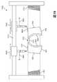
ここで図6を参照すると、一体型ニットベロ512の断面図が示されている。例示的な実施形態では、隆起要素は、第1ニット構成要素500がワンピース要素になるように、一体型ニットベロ512およびアッパー502との一体ニット構造から形成されている。この実施形態では、外側隆起要素514は第1近位端600でアッパー502に接合されており、内側隆起要素515は第2近位端601でアッパー502に接合されている。各隆起要素はアッパー502の第1の表面530からフラップ状構成で外方に延びて、一体型ニットベロ512の突き出し部分を形成している。この実施形態では、外側隆起要素514は第1近位端600から第1遠位端602まで外方に延びて、第1外向き面604および第1内向き面606を含んでいる。同様に、内側隆起要素515は第2近位端601から第2遠位端603まで外方に延びて、第2外向き面605および第2内向き面607を含んでいる。例示的な実施形態では、第1外向き面604および/または第2外向き面605は第1ニット構成要素500の各側部に向けて置いてもよいのに対し、第1内向き面606および/または第2内向き面607は一体型ニットベロ512が配置されている第1ニット構成要素500の中心に向けて置いていてもよい。 Referring now to FIG. 6, a cross-sectional view of an
くわえて、図6に図示するように、外側隆起要素514および内側隆起要素515は、第1内向き面606および/または第2内向き面607が第1の表面530に向いて置かれているように平らな構成で示されている。しかし、さまざまな実施形態では、外側隆起要素514および内側隆起要素515を含む隆起要素は、直立構成で配置してもよい。ここで図7を参照すると、外側隆起要素514および内側隆起要素515は、第1内向き面606および/または第2内向き面607が第1の表面530に対して略垂直に、または起立角度で置かれているように直立構成で示されている。いくつかの実施形態では、アッパー502を一体型ニットベロ512の両側にぴんと張るプロセス(例えば、第1ニット構成要素500をソール構造に接合して履物製品を形成することにより)が、外側隆起要素514および内側隆起要素515のそれぞれを平らな構成から直立構成へと移動させてもよい。 In addition, as illustrated in FIG. 6, the outer raised
例示的な実施形態では、一体型ニットベロ512の外側隆起要素514および内側隆起要素515は、第1ニット構成要素500の第1の表面530の上に第1の高さH1分延びていてもよい。いくつかの実施形態では、外側隆起要素514および内側隆起要素515の直立構成を使用して、締めひも開口部を一体型ニットベロ512に組み込んでもよい。この実施形態では、外側隆起要素514および内側隆起要素515の各側に沿って設けられて、第1外向き面604から第1内向き面606まで、また第2外向き面605から第2内向き面607まで貫通している複数の締めひも開口部700が示されている。いくつかの場合には、複数の締めひも開口部700は、隆起要素を形成している一体型ニットベロ512のニット構造内の空洞または開口部であってもよい。他の場合には、複数の締めひも開口部700は、前述した締めひも開口部に適した構造のいずれをも含めて、異なる構造を有していてもよい。 In the exemplary embodiment, the outer raised
図8および図9を参照すると、第2ニット構成要素800の例示的な実施形態の平面図を示している。第2ニット構成要素800は、前述したニット構成要素130および/または第1ニット構成要素500と実質的に同様であってもよい。いくつかの実施形態では、第2ニット構成要素800はアッパー802を画定する第1部分と、一体型ニットベロ812を画定する第2部分とを含む。例示的な実施形態では、第2ニット構成要素800は、一体ニット構造から形成されているアッパー802および一体型ニットベロ812を組み込んでいる。 With reference to FIGS. 8 and 9, a plan view of an exemplary embodiment of a
第1ニット構成要素500と同様に、第2ニット構成要素800は、外周および内周によって輪郭が描かれている略U字形構成を有する。この実施形態では、外周は、前周縁部803と、外側周縁部804と、内側周縁部805と、外側かかと縁部806および内側かかと縁部807を含む1対のかかと縁部とを含む。第2ニット構成要素800の内周は、足首開口部を形成してもよい外側内縁部808および内側内縁部809を含む。くわえて、第2ニット構成要素800は、アッパー802の外側面の一部を形成している第1の表面830と、アッパー802の内側面の一部を形成している反対側の第2の表面832とを有してもよい。 Similar to the
例示的な実施形態では、第2ニット構成要素800は、足首開口部に関連する第2ニット構成要素800の部分まで延びている上端814を含む一体型ニットベロ812を含んでもよい。上端814は第2ニット構成要素800の他の部分から全体的に自由であってもよい。一体型ニットベロ812は、第2ニット構成要素800のスロート区域820の前部およびスロート区域820の長さに沿って延びている一体型ニットベロ812の両側に沿って、アッパー802との一体ニット構造で形成してもよい。例示的な実施形態では、第2ニット構成要素800の一体型ニットベロ812は隆起要素を含んでいない。したがって、第1ニット構成要素500とは対照的に、第2ニット構成要素800は、一体型ニットベロ812の上に延びて外側内縁部816および内側内縁部817を形成しているアッパー802の一部を含む。より具体的には、一体型ニットベロ812の縁部は、外側内縁部816および内側内縁部817から外方に離間している第2ニット構成要素800の区域に編み込まれている。 In the exemplary embodiment, the
ここで図9を参照すると、一体型ニットベロ812の断面図が示されている。例示的な実施形態では、一体型ニットベロ812の縁部は、第2ニット構成要素800がワンピース要素になるように、アッパー802との一体ニット構造で形成されている。この実施形態では、一体型ニットベロ812の第1縁部900および第2縁部902は、一体型ニットベロ812がアッパー802の外側内縁部816および内側内縁部817の下に延びているように、アッパー802の第2の表面832と接合されている。この構成により、一体型ニットベロ812の上面は、外側内縁部816および内側内縁部817まで張り出して延びているアッパー802の部分に設けられている第2ニット構成要素800の第2の表面832に向いて置かれていてもよい。例示的な実施形態では、第2ニット構成要素800に含まれる一体型ニットベロ812の構成は、実質的に平らな状態で置かれるように提供してもよい。 Referring now to FIG. 9, a cross-sectional view of an
さまざまな実施形態において、ニット構成要素内に、着用者が履物製品の足首開口部から足を入れおよび/または足を抜くのを助けるしつらえを施してもよい。いくつかの実施形態では、ニット構成要素の一体型ニットベロは、より大きな足首開口部を可能にするように改造してもよい。図10から図15は、履物製品に組み込まれたときに、より大きな足首開口部を可能にするメカニズムを備えているニット構成要素の代替実施形態を示す。 In various embodiments, provisions may be made in the knitted component to help the wearer insert and / or remove the foot from the ankle opening of the footwear product. In some embodiments, the integral knit component of the knit component may be modified to allow for a larger ankle opening. FIGS. 10-15 illustrate an alternative embodiment of a knit component that includes a mechanism that allows for a larger ankle opening when incorporated into an article of footwear.
図10から図12は、履物製品に組み込んだときに、より大きな足首開口部を可能にするメカニズムを含むニット構成要素の代替実施例を示す。ここで図10を参照すると、部分的に一体の部分をもつ一体型ニットベロを有するニット構成要素の代替実施例の平面図が示されている。いくつかの実施形態では、第3ニット構成要素1000は、アッパー1002を画定する第1部分と、一体型ニットベロ1010を画定する第2部分とを含んでもよい。第3ニット構成要素1000は、前述したニット構成要素130、第1ニット構成要素500および/または第2ニット構成要素800と実質的に同様であってもよい。第1ニット構成要素500および/または第2ニット構成要素800と同様に、第3ニット構成要素1000は、外周および内周により輪郭が描かれる略U字形構成を有していてもよい。この実施形態では、外周は前周縁部1003と、外側周縁部1004と、内側周縁部1005と、外側かかと縁部1006および内側かかと縁部1007を含む1対のかかと縁部とを含む。第3ニット構成要素1000の内周は、足首開口部を形成してもよい外側内縁部1008と内側内縁部1009とを含む。くわえて、第3ニット構成要素1000は、アッパー1002の外側面の一部を形成している第1の表面1030と、アッパー1002の内側面の一部を形成している反対側の第2の表面1032とを有してもよい。 FIGS. 10-12 show an alternative embodiment of a knit component that includes a mechanism that allows for a larger ankle opening when incorporated into an article of footwear. Referring now to FIG. 10, there is shown a plan view of an alternative embodiment of a knit component having an integral knit tongue with a partially integral part. In some embodiments, the third
いくつかの実施形態では、第3ニット構成要素1000は、追加構造をさらに含んでもよい。例示的な実施形態では、第3ニット構成要素1000は、第3ニット構成要素1000のニット構造内に挿入されている少なくとも1つの伸張要素1040を含んでもよい。伸張要素1040に適した材料は、フィラメント(例、単繊維)、スレッド、ロープ、帯、ケーブル、または鎖の構成のヤーンまたはインレイストランドを含んでもよいが、これだけに限定されない。伸張要素1040は第3ニット構成要素1000を通って延びており、第3ニット構成要素1000内に形成されているニット構造1042内のさまざまなループの間を通過している。伸張要素1040は一般にニット構造1042内のコースに沿って延びていてよく、また伸張要素1040はニット構造1042内のウェールに沿って延びていてもよい。伸張要素1040の利点は、サポート、安定性および構造を提供することを含む。たとえば、伸張要素1040は足の周りにアッパー1002を固定するのを助け、アッパー1002の区域の変形を制限し(耐伸縮性を付与する等)、第3ニット構成要素を組み込んでいる履物製品のフィット性を高めるように締めひもと連動する。 In some embodiments, the third
本明細書で説明する実施形態で使用するためのインレイストランドまたは他の適した要素としての伸張要素、ならびにインレイストランドおよびニット構造を組み込んでいるニット構成要素を製造する方法は、2008年12月18日に出願され、2010年6月24日に特許文献1として公開された「ニット構成要素を組み込んだアッパーを有する履物製品」と題する、発明者Dua他、所有者が共通の米国特許出願第12/338,726号、および2011年3月15日に出願され、2012年9月20日に特許文献2として公表された「ニット構成要素を組み込んだ履物製品」と題する、発明者Huffa他の米国特許出願第13/048,514号の1つ以上に開示されており、これら出願の両方を参照によりその全体をこれに組み込む(本明細書において総称的に「インレイストランド案件」という)。 A method of manufacturing a stretch element as an inlay strand or other suitable element for use in the embodiments described herein, and a knit component incorporating the inlay strand and knit structure, is described in December 18, 2008. Inventor Dua et al., Commonly owned US patent application Ser. No. 12 entitled “Footwear product with upper incorporating knit components” filed on June 24, 2010 and published as US Pat. US Pat. No. 3,338,726, and inventor Huffa et al., Entitled “Footwear incorporating knitted components” filed Mar. 15, 2011 and published as U.S. Pat. Disclosed in one or more of patent applications 13 / 048,514, both of which are incorporated herein by reference in their entirety. Writing (generically referred to as "inlaid strand projects" in the present specification).
例示的な実施形態では、第3ニット構成要素1000は、アッパー1002の少なくとも一部および一体型ニットベロ1010の一部がワンピース要素になるように、一体ニット構造で形成されているアッパー1002および一体型ニットベロ1010を組み込んでいる。ある実施形態では、一体型ニットベロ1010は、一体型ニットベロ1010の両側に沿ってアッパー1002との一体ニット構造で形成されている第1部分と、第1部分との一体ニット構造で形成されているが、他の部分はアッパー1002から自由な第2部分とをさらに含んでもよい。この実施形態では、第3ニット構成要素1000は、部分的に一体の部分1012と自由部分1014とを有する一体型ニットベロ1010を含む。 In the exemplary embodiment, the third
例示的な実施形態では、部分的に一体の部分1012は第3ニット構成要素1000のスロート区域1020の中央に配置されていてもよく、かかと領域の足首開口部に隣接する距離D1から足の甲に対応する区域を越えて、足先領域に隣接する区域まで延びているとともに、第3ニット構成要素1000の外側側部と内側側部との間に延びていてもよい。ある実施形態では、部分的に一体の部分1012は、スロート区域1020の前方部分および第3ニット構成要素1000のスロート区域1020の長さに沿って延びている両側において、アッパー1002との一体ニット構造で形成されている。したがって、部分的に一体の部分1012は、部分的に一体の部分1012およびアッパー1002が共通の少なくとも1つのコースを含むように、および/または実質的に連続しているコースを含むように、スロート区域1020の前方部分ならびに外側側部および内側側部のそれぞれに沿って、アッパー1002に編み込むことにより接合されている。 In the exemplary embodiment, the partially
例示的な実施形態では、一体型ニットベロ1010は、スロート区域1020の両側に設けられて、一体型ニットベロ1010の長さに沿って延びている隆起要素を含んでもよい。隆起要素は、編みプロセスにより、アッパー1002の第1の表面1030から離れて外方に延びている一体型ニットベロ1010のフラップまたは突き出し部分になるように形成されている一体型ニットベロ1010の部分であってもよい。図10および図11に図示するように、一体型ニットベロ1010は、アッパー1002および一体型ニットベロ1010の部分的に一体の部分1012との一体ニット構造で形成されている外側隆起要素1016と内側隆起要素1015とを含む。外側隆起要素1016および/または内側隆起要素1015は、前述した外側隆起要素514および内側隆起要素515と実質的に同様で、また同様に形成されていてもよい。 In the exemplary embodiment, the
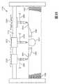
ここで図11を参照すると、例示的な実施形態において、足首開口部に隣接する第3ニット構成要素1000のスロート区域1020の上端に、自由部分1014が設けられていてもよい。ある実施形態では、自由部分1014は、スロート区域1020の後方部分1100において部分的に一体の部分1012との一体ニット構造で形成されているが、それ以外はアッパー1002および/または第3ニット構成要素1000の他の部分に接合または付着されていない。この構成により、足首開口部は、足首開口部から第3ニット構成要素1000のスロート区域1020に沿って距離D1分延びている一体型ニットベロ1010の部分的に一体の部分1012の後方部分1100の位置に対応するより大きな開口部を設けられていてもよい。一体型ニットベロ1010の自由部分1014は足首開口部内に置かれる着用者の足を覆って、第3ニット構成要素1000を組み込んでいる履物製品の快適性を高めてもよい。 Referring now to FIG. 11, in an exemplary embodiment, a
いくつかの実施形態では、一体型ニットベロ1010の部分的に一体の部分1012は、異なる種類のニット構造も含めて、多数のニット構造を含んでもよい。たとえば、部分的に一体の部分1012は第1ニット構造1102と第2ニット構造1104とを含んでもよい。第1ニット構造1102は第1ニットタイプに関連してもよく、中央に配置して、一体型ニットベロ1010に沿ってスロート区域1020の後方部分1100から前方部分まで延びていてもよい。第2ニット構造1104は第2ニットタイプに関連してもよく、一体型ニットベロ1010の周側部に沿って、第1ニット構造1102と、スロート区域1020の後方部分1100から前方部分まで同様に延びている外側隆起要素1016および内側隆起要素1015それぞれとの間に配置されていてもよい。ある実施形態では、第1ニット構造1102および第2ニット構造1104は、異なるニット構造または異なるタイプのニット構造であってもよい。たとえば、いくつかの場合には、第1ニット構造1102はメッシュまたは同様なニットタイプであってもよく、第2ニット構造1104はジャージーまたは同様なニットタイプであってもよい。他の場合には、第1ニット構造1102はダブルニットジャージー構造であってもよく、第2ニット構造1104はシングルニットジャージー構造であってもよい。図12に図示するように、第1ニット構造1102は、一体型ニットベロ1010の部分的に一体の部分1012の長さに沿って延びている第1ニット構造1102のいずれかの周側部に設けられている第2ニット構造1104よりも大きい厚さを有していてもよい。 In some embodiments, the partially
いくつかの実施形態では、締めひもを受ける締めひも開口部は、伸張要素1040によって提供してもよい。例示的な実施形態では、第3ニット構成要素1000のスロート区域1020の両側の外側隆起要素1016および内側隆起要素1015に隣接するニット構造1042から張り出して延びている伸張要素1040の部分に、複数の締めひもループ1110を設けていてもよい。この構成により、締めひも(図示せず)を複数の締めひもループ1110を通して配置して、第3ニット構成要素1000を組み込んでいる履物製品を着用者の足に固定するのを助けてもよい。他の実施形態では、締めひも開口部は、前述した締めひも開口部に適した構造のいずれをも含めて、異なる構造を有していてもよい。 In some embodiments, a lace opening that receives a lace may be provided by an
図13から図15は、履物製品に組み込まれたときに、より大きな足首開口部を可能にするメカニズムを有するニット構成要素の別の代替実施形態を示す。ここで図13を参照すると、一部分離しているニット要素をもつ一体型ニットベロとともにニット構成要素の代替実施形態の平面図が示されている。いくつかの実施形態では、第4ニット構成要素1300は、アッパー1302を画定する第1部分と、一体型ニットベロ1310を画定する第2部分とを含んでもよい。第4ニット構成要素1300は、前述したニット構成要素130、第1ニット構成要素500、第2ニット構成要素800、および/または第3ニット構成要素1000と実質的に同様な1つ以上の特徴を共有してもよい。ニット構成要素の前の実施形態と同様に、第4ニット構成要素1300は、外周および内周によって輪郭が描かれる略U字形の構成を同様に有してもよい。この実施形態では、外周は前周縁部1303と、外側周縁部1304と、内側周縁部1305と、外側かかと縁部1306および内側かかと縁部1307を含む1対のかかと縁部とを含む。第4ニット構成要素1300の内周は、足首開口部を形成してもよい外側内縁部1308および内側内縁部1309を含む。くわえて、第4ニット構成要素1300は、アッパー1302の外側面の一部を形成している第1の表面1330と、アッパー1302の内側面の一部を形成している反対側の第2の表面1332とを有してもよい。 FIGS. 13-15 illustrate another alternative embodiment of a knitted component having a mechanism that allows for a larger ankle opening when incorporated into an article of footwear. Referring now to FIG. 13, there is shown a plan view of an alternative embodiment of a knit component with an integral knit tongue having a partially separated knit element. In some embodiments, the
いくつかの実施形態では、第4ニット構成要素1300は、第4ニット構成要素1300のニット構造1342内に挿入している少なくとも1つの伸張要素1340を含めて、追加構造をさらに含んでもよい。伸張要素1340は、インレイストランド案件で開示されるような適した材料ならびに伸張要素およびニット構造を組み込んでいるニット構成要素の製造方法を含め、前述した伸張要素1040と実質的に同様としてもよい。例示的な実施形態では、伸張要素1340は、締めひもを受けるように構成されていてもよい複数の締めひもループ1344をさらに含んでもよい。複数の締めひもループ1344は、ニット構造1342から張り出して延びている伸張要素1340の部分に設けられていてもよく、前述した締めひもループ1110と実質的に同様な構造を有していてもよい。いくつかの場合には、締めひもループ1344は締めひもを受けるための締めひも開口部として機能してもよい。他の場合には、締めひもループ1344は、一体型ニットベロ1310の隆起要素内に設けられている1つ以上の締めひも開口部と協働して、締めひもを受けてもよい。さらに他の場合には、締めひもループ1344は隆起要素内に設けられている締めひも開口部を通って設けられていてもよく、アッパー1302のスロート区域1320を通って延びている締めひもを受けてもよい。 In some embodiments, the
例示的な実施形態では、第4ニット構成要素1300は、アッパー1302の少なくとも一部および一体型ニットベロ1310の一部がワンピース要素になるように、一体ニット構造で形成されているアッパー1302および一体型ニットベロ1310を組み込んでいる。ある実施形態では、アッパー1302の部分は多数のニット要素層から形成されていてもよい。したがって、一体型ニットベロ1310はニット要素層が少なくとも1つある一体ニット構造で形成されていてもよい。 In the exemplary embodiment, the fourth
いくつかの実施形態では、一体型ニットベロ1310は第4ニット構成要素1300のスロート区域1320の中央に配置されていてもよく、かかと領域の足首開口部に隣接する上端1314から足の甲に対応する区域を越えて、足先領域に隣接する区域まで延びているとともに、アッパー1302の外側側部と内側側部との間に延びていてもよい。例示的な実施形態では、一体型ニットベロ1310は、スロート区域1320の前方部分および第4ニット構成要素1300のスロート区域1320の長さに沿って延びている両側において、アッパー1302に関連する少なくとも1つのニット要素層との一体ニット構造で形成されている。 In some embodiments, the
例示的な実施形態では、第4ニット構成要素1300は、スロート区域1320の両側に設けられて、一体型ニットベロ1310の長さに沿って延びている隆起要素をさらに含んでもよい。図13から図15に図示するように、第4ニット構成要素1300は、アッパー1302の少なくとも1つのニット要素層との一体ニット構造で形成されている外側隆起要素1312および内側隆起要素1313を含む。外側隆起要素1312および/または内側隆起要素1313は、前述した外側隆起要素514、1016、および/または内側隆起要素515、1015と実質的に同様で、同様に形成されていてもよい。 In the exemplary embodiment, the fourth
いくつかの実施形態では、一体型ニットベロ1310を形成している第4ニット構成要素1300の部分は、第4ニット構成要素1300の残りの部分とは異なる材料から作ってもよい。例示的な実施形態では、一体型ニットベロ1310は弾力性の程度の大きい弾性糸から作ってもよい一方で、第4ニット構成要素1300の残りの部分は実質的に弾性のない、または弾性糸と比較して弾力性の程度が小さいレギュラーヤーンから作ってもよい。この構成により、第4ニット構成要素1300の一体型ニットベロ部分1310は、第4ニット構成要素1300を組み込んでいる履物製品の足首開口部から入れられる着用者の足を収容するように、スロート区域1320の伸縮を可能にして構成してもよい。 In some embodiments, the portion of the fourth
さらに、いくつかの実施形態では、第2ニット要素から一部分離している第4ニット構成要素1300の第1ニット要素層との一体ニット構造を成す一体型ニットベロ1310を形成することにより、スロート区域1320はさらに、第4ニット構成要素1300を組み込んでいる履物製品の足首開口部をより大きくできるように伸縮を可能にしてもよい。第1ニット要素層および第2ニット要素層の一部分離は、図14および図15に図示する。 Further, in some embodiments, the
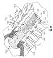
ここで図14および図15を参照すると、この実施形態では、アッパー1302は第4ニット構成要素1300の第1の表面1330に関連する第1ニット要素層1400と、第4ニット構成要素1300の第2の表面1332に関連する第2ニット要素層1402とを含んでもよい。例示的な実施形態では、第1ニット要素層1400および第2ニット要素層1402は、一体型ニットベロ1310に関連する第4ニット構成要素1300の部分で一部分離されていてもよい。すなわち、第4ニット構成要素1300の他の部分は、片側に第1の表面1330を、反対側に第2の表面1332を有するシングルニット要素を含んでもよいが、第4ニット構成要素1300の一部分離している部分は互いに隣接して設けられているが、その表面全体に沿って接合されてはいない個別の第1ニット要素層1400および第2ニット要素層1402を含む。したがって、第1の表面1330は第1ニット要素層1400の片側に設けられ、第2の表面1332は第2ニット要素層1402の片側に設けられている。第4ニット構成要素1300の他の部分では、第1ニット要素層1400および第2ニット要素層1402は編みプロセスにより互いに再接合するので、第4ニット構成要素1300の残りの部分を通って延びているシングルニット要素を形成してもよい。 Referring now to FIGS. 14 and 15, in this embodiment, upper 1302 includes first knitted
例示的な実施形態では、一体型ニットベロ1310は、少なくとも1つのニット要素層との一体ニット構造で形成されていてもよい。ある実施形態では、一体型ニットベロ1310は第2ニット要素層1402との一体ニット構造で形成されている。図14および図15に図示するように、一体型ニットベロ1310および第2ニット要素層1402が共通の少なくとも1つのコースを含むように、および/またはスロート区域1320を通って延びているアッパー1302の両側に沿って一体型ニットベロ1310と第2ニット要素層1402との間に実質的に連続しているコースを含むように、一体型ニットベロ1310はスロート区域1320の外側側部および内側側部のそれぞれに沿ってアッパー1302の第2ニット要素層1402に編み込むことによって接合されている。同様に、例示的な実施形態では、外側隆起要素1312および内側隆起要素1313を含めて隆起要素は、第1ニット要素層1400との一体ニット構造で形成されていてもよい。 In an exemplary embodiment, the
いくつかの実施形態では、一体型ニットベロ1310は、前述したように異なるタイプのニット構造も含め、多数のニット構造を含んでもよい。たとえば、一体型ニットベロ1310は第1ニット構造1410および第2ニット構造1412を含んでもよい。第1ニット構造1410は第1ニットタイプに関連してもよく、中央に配置して、一体型ニットベロ1310に沿ってスロート区域1320の後方部分から前方部分まで延びていてもよい。第2ニット構造1412は第2ニットタイプに関連してもよく、一体型ニットベロ1310の周側部に沿って、第1ニット構造1410と、スロート区域1320の後方部分から前方部分に同様に延びている外側隆起要素1312および内側隆起要素1313それぞれとの間に配置してもよい。この実施形態では、第1ニット構造1410および第2ニット構造1412は同様に弾性糸で作ってもよいが、第1ニット構造1410はダブルニットジャージー構造であってもよく、第2ニット構造1412はシングルニットジャージー構造であってもよい。図14および図15に図示するように、第1ニット構造1410は第2ニット構造1412よりも大きい厚さを有してもよい。 In some embodiments, the
いくつかの実施形態では、第1ニット要素層1400および第2ニット要素層1402の部分は、一体型ニットベロ1310に沿って所望の場所で第1ニット要素層1400および第2ニット要素層1402を固定するように接合されていてもよい。図14に図示するように、外側隆起要素1312が一体型ニットベロ1310の上に外方に延び始める第1端1406で、第1ニット要素層1400を第2ニット要素層1402を接合するために第1ヤーン1404を使用してもよい。同様に、内側隆起要素1313が一体型ニットベロ1310の上に外方に延び始める第2端1405で、第1ニット要素層1400を第2ニット要素層1402に接合するために第2ヤーン1403を使用してもよい。いくつかの場合には、第1ヤーン1404および/または第2ヤーン1403は、編みプロセス中に第1ニット要素層1400を第2ニット要素層1402に接合する第4ニット構成要素1300からの1本のヤーンまたは複数本のヤーンを含んでもよい。他の場合には、第1ヤーン1404および/または第2ヤーン1403は、編みプロセス後に第1ニット要素層1400を第2ニット要素層1402に接合するために使用される編み目または複数の編み目を含んでもよい。 In some embodiments, portions of the first
ある実施形態では、第1ヤーン1404および/または第2ヤーン1403の位置は、伸張要素1340の締めひもループ1344のうちの1つ以上と一致するように選択してもよい。この構成により、第1ニット要素層1400および第2ニット要素層1402は、第4ニット構成要素1300を組み込んでいる履物製品の着用者の足に適合するようにアッパー1302のスロート区域1320を固定するために締めひもを使用してもよい場所に対応する位置で、互いに固定してもよい。対して、図15に図示する第4ニット構成要素1300の一部分離している部分は、第1ニット要素層1400を第2ニット要素層1402に接合する第1ヤーン1404および/または第2ヤーン1403を含んでいない。したがって、一部分離している部分では、第1ニット要素層1400および第2ニット要素層1402は互いに独立して動くようにされていてもよい。この構成は、弾性糸を使用して一体型ニットベロ1310を形成している第2ニット要素層の1つ以上の部分を形成することと合わせて、第4ニット構成要素1300を組み込んでいる履物製品の足首開口部をより大きくできるように、スロート区域1320を伸縮させることができる。 In certain embodiments, the position of the
ニット構成要素の編みプロセス
図16から図29は、本明細書で説明する原理に従いニット構成要素の製造に使用してもよいさまざまな編みプロセスを示している。本明細書で説明するさまざまな実施形態において、ある特定のニット構成要素のさまざまなニット構造を、ニットタイプおよびヤーンの種類を含め、さまざまなニット構造の種類を用いて作製してもよい。Knitting Component Knitting Process FIGS. 16-29 illustrate various knitting processes that may be used to manufacture a knitted component in accordance with the principles described herein. In the various embodiments described herein, various knit structures of a particular knit component may be made using various knit structure types, including knit types and yarn types.
例示的な実施形態では、内側側部および外側側部に沿って隆起要素を含むニット構成要素の一体型ニットベロは、特定の編みプロセスを用いて形成してもよい。参照のために、図16は、たとえば、隆起要素142、隆起要素514、515、隆起要素1015、1016、および/または隆起要素1312、1313のいずれをも含め、一体型ニットベロに関連した隆起要素を編みプロセス1600を用いて形成する方法のループ図を示す。 In an exemplary embodiment, an integral knit bevel of knit components that includes raised elements along the inner and outer sides may be formed using a specific knitting process. For reference, FIG. 16 shows raised elements associated with an integral knit tongue, including, for example, raised
図16に図示するように、隆起要素を有する一体型ニットベロの編みプロセス1600は、一体型ニットベロを作製するために行われる編み操作の方向およびタイプを示すループ図を含む。ニット構成要素の残りの部分はあらゆる適した編みプロセスに従って作製してもよく、編みプロセス1600はニット構成要素全体の一体型ニットベロ部分の例示的な編みプロセスを詳述していることは理解されるべきである。したがって、第1ステップ1601で、ヤーンは編み機の後床に移される。次に、第2ステップ1602で、図示する第1方向に沿ってヤーンが編まれ、さらに第3ステップ1603で第2の反対方向に沿って戻る。次に、第4ステップ1604で、編み機の前床にヤーンが移されて、第5ステップ1605で第1方向に沿ってヤーンが編まれる。このプロセスにより、一体型ニットベロの片側に沿った隆起要素が形成される。一体型ニットベロの中央部分を形成する第5ステップ1605のために例示的なニットタイプを図示しているが、いずれか所望のニット構造を有する一体型ニットベロの中央部分を作製するのにあらゆる適したニットタイプを使用してもよい。 As illustrated in FIG. 16, the
同様に、第5ステップ1605から、一体型ニットベロの反対側に設けられている隆起要素も形成してもよい。図16に図示するように、第5ステップ1605に関連した編み完了後、第6ステップ1606でヤーンを編み機の後床に移してもよく、第7ステップ1607に示す第2方向に沿ってヤーンを編み、さらに第8ステップ1608で反対の第1方向に沿って戻す。それから、第9ステップ1609でヤーンを編み機の前床に戻してもよく、第10ステップ1610で一体型ニットベロの幅全体に沿って第2方向に沿いヤーンを編む。例示的な編みプロセス1600を複数回繰り返して、ニット構成要素に沿って所望の長さを有する隆起要素を備える一体型ニットベロを作製してもよい。同様に、編みプロセス1600に関連する針の数を変更することによって、一体型ニットベロの部分をより広くまたはより狭くしてもよい。たとえば、第5ステップ1605および/または第10ステップ1610を含む編みプロセス1600の部分は、一体型ニットベロの幅を対応して増やすまたは減らすために、より多くまたはより少ない針の数を含むように変えてもよい。くわえて、前述したように、ここに図示していない他の編みプロセスを使用して、ニット構成要素の残りの部分を作製してもよい。 Similarly, a raised element provided on the opposite side of the integrated knit tongue may be formed from the
さらに、図16に図示するニットタイプは例示的なものであり、異なる実施形態では変えてもよい。たとえば、編みプロセス1600に示すように、各隆起要素はダブルジャージー・ハーフゲージニットから作製されているが、一体型ニットベロの中央部分はシングルジャージー・ハーフゲージニットから作製されている。しかし、他の実施形態では、1つ以上のニットタイプを変えてもよい。たとえば、いくつかの場合には、一体型ニットベロの中央部分はフルゲージ(もしくは「全針」)シングルまたはダブルジャージーニットの1つ以上の部分を含んでもよい。他の場合には、一体型ニットベロの中央部分に沿ったさまざまなニットタイプの幅を、たとえば、前述したように異なる針の数を使用することにより、繰り返し変えてもよい。さらに他の場合は、ニット、タック編みもしくは浮き編みのさまざまな組合せを採用するニットタイプおよび/またはニット構造の組合せを含んでもよい。 Furthermore, the knit type illustrated in FIG. 16 is exemplary and may be varied in different embodiments. For example, as shown in the
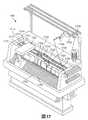
編みは手で行ってもよいが、ニット構成要素の商業的な製造は一般に編み機で行われる。図17は、ニット構成要素130、第1ニット構成要素500、第2ニット構成要素800、第3ニット構成要素1000、および/または第4ニット構成要素1300を含め、前の実施形態で説明したニット構成要素のいずれも、ならびに明示的に図示または説明していないが本明細書に説明される原理に従って作製されるニット構成要素の他の構成を生産するのに適した編み機1700の例示的な実施形態を示す。この実施形態では、編み機1700は、例示のためにVベッド型横編み機の構成を有するが、ニット構成要素またはニット構成要素の部分のいずれも他の種類の編み機で生産してもよい。 Although knitting may be done by hand, the commercial manufacture of knitted components is typically done on a knitting machine. FIG. 17 illustrates the knit described in the previous embodiment, including the
例示的な実施形態では、編み機1700は、互いに対して角度を成すことによりVベッドを形成している前針床1701および後針床702の2つの針床を含んでもよい。前針床1701および後針床1702のそれぞれは、前針床1701に関連する針1703および後針床1702に関連する針1704を含め、共通平面上にある複数の個々の針を含む。すなわち、前針床1701からの針1703は第1平面上にあり、後針床1702からの針1704は第2平面上にある。第1平面および第2平面(つまり、2つの針床1701、1702)は互いに対して角度を成しており、相交わって編み機1700の幅の大部分に沿って延びている交差部を形成する。以下さらに詳細に説明するように、針1703、1704はそれぞれ後退する第1位置と、延伸する第2位置とを有する。第1位置では、針1703、1704は第1平面と第2平面とが相交わる交差部から離れている。しかし、第2位置では、針1703、1704は第1平面と第2平面とが相交わる交差部を通過する。 In an exemplary embodiment, the
前方レール1710および後方レール1711を含む1対のレールが、針床1701、1702の交差部の上にかつ平行に延びており、複数の標準フィーダー1720およびコンビネーションフィーダー1722の装着ポイントを提供する。各レール1710、1711は2つの側部を有し、そのそれぞれが1つの標準フィーダー1720または1つのコンビネーションフィーダー1722のいずれかを収容する。この実施形態では、レール1710、1711は前側部1712および後側部1714を含む。このように、編み機1700は合計で4つのフィーダー1720および1722を含んでもよい。図示するように、最前列のレールである前方レール1710は対向する側部に1つのコンビネーションフィーダー1722および1つの標準フィーダー1720を含み、最後列のレールである後方レール1711は対向する側部に2つの標準フィーダー1720を含んでいる。2つのレール1710、1711を図示しているが、編み機1700のさらなる構成は追加レールを組み込んで、より多くの標準フィーダー1720および/またはコンビネーションフィーダー1722の装着ポイントを提供してもよい。 A pair of rails, including a
キャリッジ1730の作用により、フィーダー1720および1722はレール1710、1711および針床1701、1702に沿って移動し、それによって針1703、1704にヤーンを供給する。図17に図示するように、ヤーン1724はスプール1726によってコンビネーションフィーダー1722に供給される。より具体的には、ヤーン1724はスプール1726からさまざまなヤーンガイド1728、ヤーン引きばね、およびヤーンテンショナーに延びてから、コンビネーションフィーダー1722に進入する。図示していないが、スプール1726と実質的に同様にヤーンをフィーダー1720に供給するために、追加スプールを使用してもよい。 By the action of the
標準フィーダー1720は、編み機1700などのVベッド型横編み機で従来から使用されている。すなわち、既存の編み機は標準フィーダー1720を組み込んでいる。各標準フィーダー1720は、針1703、1704が編み、タック編みおよび浮き編みするために操作するヤーンを供給する能力を有する。比較として、コンビネーションフィーダー1722は、針1703、1704が編み、タック編みおよび浮き編みするヤーン(例、ヤーン1724)を供給する能力を有するとともに、コンビネーションフィーダー1722はヤーンを挿入する能力をさらに有する。また、コンビネーションフィーダー1722は、ヤーンまたは他のタイプのストランド(例、フィラメント、スレッド、ロープ、帯、ケーブルもしくは鎖)を含め、さまざまな異なる伸張要素を挿入する能力を有する。したがって、コンビネーションフィーダー1722は各標準フィーダー1720よりも優れた汎用性を示す。
標準フィーダー1720およびコンビネーションフィーダー1722は、前記参照によりその開示が組み込まれた2012年2月20日に出願された「ベロを有するニット構成要素を組み込んだ履物製品」と題する特許文献3に説明される標準フィーダーおよびコンビネーションフィーダーの構造と実質的に同様な構成を有していてもよい。 A
ここで、ニット構成要素を製造するために編み機1700を操作する方法を詳細に説明する。また、以下の説明は編みプロセス中の1つ以上の標準フィーダー1720および/またはコンビネーションフィーダー1722の操作を明示する。本明細書で述べる編みプロセスは、前記説明した実施形態のニット構成要素と同様なニット構成要素を含め、あらゆるニット構成要素であってもよいさまざまなニット構成要素の形成に関する。説明のために、図面では、ニット構造を例示できるように、図にはニット構成要素の比較的小さい区画しか示していない。また、編み機1700およびニット構成要素のさまざまな要素の縮尺または比率は、編みプロセスをよりよく例示するために拡大している。ニット構成要素は針床1701、1702間で形成されるが、図18から図29において例示のために、(a)編みプロセスの説明中により見えやすいように、および(b)互いに対する、また針床1701、1702に対するニット構成要素の部分の位置を示すために、ニット構成要素を針床1701、1702に隣接して示していることは理解されるべきである。また、1本のレール、少数の標準フィーダーおよびコンビネーションフィーダーを図示しているが、追加のレール、標準フィーダーおよびコンビネーションフィーダーを使用してもよい。したがって、編み機1700の全体構造は、編みプロセスの説明のために簡略化している。 Here, a method for operating the
図18から図21は、前述した第1ニット構成要素500としてニット構成要素を編む例示的なプロセスを示す。図18を参照すると、前針床1701に関連する針1703、後針床1702に関連する針1704、および前方レール1710を含む編み機1700の一部が示されている。さらに、この実施形態では、編み機1700は、前述した標準フィーダー1720と実質的に同様な第1標準フィーダー1800および第2標準フィーダー1802を含んでもよい。第1標準フィーダー1800は前方レール1710の前側部に固定されていてもよく、第2標準フィーダー1802は前方レール1710の後側部に固定されていてもよい。他の実施形態では、追加のフィーダーを使用してもよく、前方レール1710および/または後レール1711の前側部もしくは後側部に配置してもよい。 18-21 illustrate an exemplary process for knitting a knit component as the
この実施形態では、スプール(図示せず)から第1ヤーン1801が第1標準フィーダー1800を通過し、ヤーン1801の一端が第1標準フィーダー1800の末端の給糸先端部から外方に延びている。ヤーン1801が図示されているが、あらゆる他のストランド(例、フィラメント、スレッド、ロープ、帯、ケーブル、鎖またはヤーン)が第1標準フィーダー1800を通過してもよい。第2ヤーン1803も同様に第2標準フィーダー1802を通過して、給糸先端部から外方に延びている。例示的な実施形態では、第1ヤーン1801および第2ヤーン1803は、第1ニット構成要素500の部分を形成するために使用してもよい。この実施形態では、第1ヤーン1801のループが第1ニット構成要素500の内側かかと縁部507の最上コースを形成し、針1703および針1704の末端に配置されているフックによって保持されている状態が示されている。同様に、第2ヤーン1803のループは第1ニット構成要素500の外側かかと縁部506を形成するために使用してもよい。
In this embodiment, a
次に、図19に示すように、編み機1700は同様なプロセスを用いて、第1ニット構成要素500を形成する材料に追加コースを追加して、一体型ニットベロ512の外側周縁部504、内側周縁部505、外側内縁部508、内側内縁部509および前内縁部510を含め、さらなる部分を形成してもよい。この実施形態では、第1標準フィーダー1800および第2標準フィーダー1802は、前記図16に図示するループ図に従って一体型ニットベロ512を形成してもよい。図20は、編み機1700が一体型ニットベロ512、外側隆起要素514、内側隆起要素515、およびアッパー502を形成する第1ニット構成要素500の残りの部分に関連するコースを完了した状態を示す。図21は、編み機1700が第1ニット構成要素500を形成する編みプロセスはほぼ完了した状態を示す。同様なプロセスを用いて追加コースを追加することにより、第1ニット構成要素500を完了してもよい。
Next, as shown in FIG. 19, the
図22から図25は、前述した第3ニット構成要素1000としてのニット構成要素を編む例示的なプロセスを示す。図22を参照すると、前針床1701に関連する針1703、後針床1702に関連する針1704および前方レール1710を含む編み機1700の一部が示されている。さらに、この実施形態では、編み機1700は、前述した標準フィーダー1720と実質的に同様な第1標準フィーダー2200および第2標準フィーダー2204と、前述したコンビネーションフィーダー1722と実質的に同様なコンビネーションフィーダー2202とを含んでもよい。第1標準フィーダー1800およびコンビネーションフィーダー2202は前方レール1710の前側部に固定されていてもよく、第2標準フィーダー2204は前方レール1710の後側部に固定されていてもよい。他の実施形態では、追加フィーダーを使用してもよく、前方レール1710および/または後レール1711の前側部もしくは後側部に配置していてもよい。 22-25 illustrate an exemplary process for knitting a knit component as the
この実施形態では、スプール(図示せず)からの第1ヤーン2201は第1標準フィーダー2200を通過し、ヤーン2201の一端が第1標準フィーダー2200の末端の給糸先端部から外方に延びている。ヤーン2201が図示されているが、他のあらゆるストランド(例、フィラメント、スレッド、ロープ、帯、ケーブル、鎖またはヤーン)が第1標準フィーダー2200を通過してもよい。第2ヤーン2205は同様に第2標準フィーダー2204を通過し、給糸先端部から外方に延びている。第3ヤーン2203はコンビネーションフィーダー2202を通過して給糸先端部に向かう。例示的な実施形態では、第3ヤーン2203は第1ヤーン2201および/または第2ヤーン2205とは異なるタイプのヤーンであってもよい。この実施形態では、第3ヤーン2203は伸張要素または他のインレイストランドであってもよい。例示的な実施形態では、第1ヤーン2201および第2ヤーン2205を第3ニット構成要素1000のニット要素の部分を形成するのに使用してもよい一方、第3ヤーン2203は第3ニット構成要素1000の伸張要素としてニット要素内に挿入してもよい。しかし、他の実施形態では、第3ヤーン2203は第3ニット構成要素1000のニット要素の部分を形成するために使用してもよい。 In this embodiment, the
この実施形態では、第1ヤーン2201のループおよび第2ヤーン2205のループが、第3ニット構成要素1000の一体型ニットベロ1010の自由部分1014を形成するとともに、針1703および針1704の末端に配置されているフックによって保持されている状態が示されている。さらに、図23は、編み機1700が自由部分1014を形成するコースが完了した状態を示す。いくつかの実施形態では、自由部分1014の少なくとも最終コースは比較的詰んだまたは密な目のクロスタック編みを含んで、編みプロセスの後の段階で、一体型ニットベロ1010の自由部分1014が一体型ニットベロ1010の残りの部分と接合するのに針床1701、1702に確実に適切な様式で位置付けられたままにするようにしてもよい。
In this embodiment, the loop of the
ここで、編み機1700は、前述した同様な編みプロセスに従って、第3ニット構成要素1000を形成するニット要素の残りの部分を形成するプロセスを始める。例示的な実施形態では、さらに、第1ヤーン2201のループは第3ニット構成要素1000の内側かかと縁部1007の最上コースを形成し始めてもよく、第2ヤーン2205のループは第3ニット構成要素1000の外側かかと縁部1006の形成に使用してもよい。 Here, the
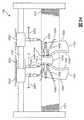
ここで図24を参照して、編みプロセスを続けると、第1標準フィーダー2200および第2標準フィーダー2204は、一体型ニットベロ1010の外側周縁部1004、内側周縁部1005、外側内縁部1008、内側内縁部1009および部分的に一体の部分1012を含め、第3ニット構成要素1000にコースを追加し続けてもよい。この実施形態では、第1標準フィーダー2200および第2標準フィーダー2204は、前記図16に図示するループ図に従い、一体型ニットベロ1010の部分的に一体の部分1012を形成してもよい。さらに、この実施形態では、コンビネーションフィーダー2202は、図24に図示するように、またインレイストランド案件に述べられる編みプロセスに従って、伸張要素1040を形成するために第3ヤーン2203を挿入する。 Referring now to FIG. 24, when the knitting process is continued, the first
例示的な実施形態では、図23および図24に図示する編みプロセス中、第3ニット構成要素1000に連続コースが形成されながら、第3ニット構成要素1000の部分が下方に移動して、自由部分1014に重なるとき、一体型ニットベロ1010の自由部分1014は針床1701、1702に対して固定されたままとしてもよい。これは、第3ニット構成要素1000の残りとともに形成される一体型ニットベロ1010の部分的に一体の部分1012に自由部分1014を接合する予定のコースが形成されるまで続く。図25は、編み機1700が第3ニット構成要素1000を形成する編みプロセスをほぼ完了している状態を示す。同様なプロセスを使用して追加コースを追加することにより、第3ニット構成要素1000を完了してもよい。 In the exemplary embodiment, during the knitting process illustrated in FIGS. 23 and 24, a continuous course is formed in the third
さらに、図22から図25に図示する編みプロセスでは、第1レール1710上のさまざまなフィーダーの相対位置が、各それぞれのフィーダーによって形成される第3ニット構成要素1000の部分を制限してもよい。たとえば、コンビネーションフィーダー2202の配置のために、第1標準フィーダー2200は一体型ニットベロ1010の内側側部に沿って、部分的に一体の部分1010全体に第3ニット構成要素1000の(第1の表面1030および第2の表面1032にそれぞれ関連する)前部分および後部分の両方を形成できるが、外側側部に沿った第3ニット構成要素1000の部分の形成は制限されてもよい。同様に、第2標準フィーダー2204は一体型ニットベロ1010の外側側部に沿って、部分的に一体の部分1012にわたり第3ニット構成要素1000の前後部分両方を形成できるが、内側側部に沿った第3ニット構成要素1000の部分の形成は制限されてもよい。この構成により、図22から図25に図示する編みプロセスは、特定のフィーダーを第3ニット構成要素1000の特定の部分を形成するのに使用することを要求してもよい。 Further, in the knitting process illustrated in FIGS. 22-25, the relative positions of the various feeders on the
図26から図29は、前述した第4ニット構成要素1300と同様なニット構成要素を編む例示的なプロセスを示す。図26を参照すると、前針床1701に関連する針1703、後針床1702に関連する針1704および前方レール1710を含む編み機1700の一部が示されている。さらに、この実施形態では、編み機1700は、前述した標準フィーダー1720と実質的に同様な第1標準フィーダー2600、第2標準フィーダー2602および第3標準フィーダー2604を含んでもよい。くわえて、第4ニット構成要素1300が伸張要素を含む実施形態では、前述したコンビネーションフィーダー1722と実質的に同様なコンビネーションフィーダー(図示せず)を含めて、第3ニット構成要素1000の編みプロセスに関して前述したプロセスに従い、またインレイストランド案件で説明するように、伸張要素1340を形成してもよい。そのため、例示しやすくするために、図26から図29では、第4ニット構成要素1300は伸張要素1340を含まずに示す。 FIGS. 26-29 illustrate an exemplary process for knitting a knit component similar to the
再び図26を参照すると、第1標準フィーダー2600および第2標準フィーダー2602は前方レール1710の前側部に固定されていてもよく、第3標準フィーダー2604は前方レール1710の後側部に固定されていてもよい。他の実施形態では、追加フィーダーを使用してもよく、前方レール1710および/または後レース1711の前側部もしくは後側部に配置していてもよい。 Referring to FIG. 26 again, the first
この実施形態では、スプール(図示せず)からの第1ヤーン2601は第1標準フィーダー2600を通過し、ヤーン2601の一端は第1標準フィーダー2600の末端の給糸先端部から外方に延びている。ヤーン2601が図示されているが、他のあらゆるストランド(例、フィラメント、スレッド、ロープ、帯、ケーブル、鎖またはヤーン)が第1標準フィーダー2600を通過してもよい。第2ヤーン2603は同様に第2標準フィーダー2602を通過し、給糸先端部から外方に延びている。第3ヤーン2605も同様に第3標準フィーダー2604を通過して給糸先端部に向かう。例示的な実施形態では、第2ヤーン2603は第1ヤーン2601および/または第3ヤーン2605とは異なるタイプのヤーンであってもよい。この実施形態では、第2ヤーン2603は、実質的に弾性のないヤーンまたは弾力性の量もしくは程度が小さいヤーンであってもよい第1ヤーン2601および/または第3ヤーン2605よりも、弾力性の量もしくは程度が大きい弾性糸であってもよい。例示的な実施形態では、第1ヤーン2601および第3ヤーン2605は第4ニット構成要素1300を形成するニット要素の外側部分および内側部分を形成するのに使用してもよいのに対し、第2ヤーン2603は、第4ニット構成要素1300のスロート区域1320内の中央に配置されている一体型ニットベロ1310の弾性部分を形成するために使用してもよい。しかし、他の実施形態では、第2ヤーン2603は第4ニット構成要素1300のニット要素の他の部分を形成するためにさらに使用してもよい。 In this embodiment, the
ここで図27を参照すると、第1ヤーン2601のループが第4ニット構成要素1300の内側かかと縁部1307の最上コースを形成している状態を示しており、第3ヤーン2605のループは第4ニット構成要素1300の外側かかと縁部1306を形成するために使用してもよい。第2ヤーン2603は第4ニット構成要素1300のどの部分の形成にもまだ使用されていない。次に、図28に図示するように、編み機1700は同様なプロセスを用いて、第4ニット構成要素1300を形成する材料に追加コースを追加して、外側周縁部1304、内側周縁部1305、外側内縁部1308および内側内縁部1309を含め、さらなる部分を形成してもよい。くわえて、この時点で、第2標準フィーダー2602は第2ヤーン2603を使用して、針床1701、1702から完成した上端1314まで延びている一体型ニットベロ1310を含め、第4ニット構成要素1300の部分を形成し始めていてもよい。
Referring now to FIG. 27, the loop of the
この実施形態では、第4ニット構成要素1300のスロート区域1320が伸縮することができるように、第2標準フィーダー2602は弾性糸を使用して一体型ニットベロ1310を形成してもよい。くわえて、第4ニット構成要素1300は前述したように1つ以上の分離したニット層を有して形成してもよい。図29は、編み機1700が一体型ニットベロ1310およびアッパー1302を形成する第4ニット構成要素1300の残りの部分を編むことに関連するコースを完了した状態を示す。同様なプロセスを用いて追加コースを追加することにより、第4ニット構成要素1300を完了してもよい。 In this embodiment, the
さらに、図26から図29に図示する編みプロセスでは、第1レール1710上のさまざまなフィーダーの相対位置が、それぞれのフィーダーによって形成される第4ニット構成要素1300の部分を制限してもよい。たとえば、第2標準フィーダー2602の配置は弾性の第2ヤーン2603を用いて一体型ニットベロ1310を形成する必要があるため、第1標準フィーダー2600は第4ニット構成要素1300の内側側部のみに沿って第4ニット構成要素1300の(第1の表面1330および第2の表面1332にそれぞれ関連する)前部分および後部分の両方を形成してもよい。同様に、第3標準フィーダー2604は第4ニット構成要素1300の外側側部のみに沿って、第4ニット構成要素1300の前後部分両方を形成してもよい。したがって、第2標準フィーダー2602を使用して、第4ニット構成要素1300の外側側部と内側側部との間にまたがる一体型ニットベロ1310を形成してもよい。この構成により、図26から図29に図示する編みプロセスは、特定のフィーダーを第4ニット構成要素1300の特定の部分を形成するのに使用することを要求してもよい。 Further, in the knitting process illustrated in FIGS. 26-29, the relative positions of the various feeders on the
既に説明し、図16から図29に図示したニット構成要素を編むプロセスおよび方法は例示的なものであり、網羅的なものではない。そのため、本明細書で説明した実施形態の特徴を含む追加のニット構成要素および本明細書で明示的に説明していない同様なニット構成要素は、前記および/またはインレイストランド案件で説明されるニット構成要素を編む方法と実質的に同様な1つ以上の編みプロセスを用いて作製してもよいことは理解されるべきである。 The processes and methods for knitting the knit components already described and illustrated in FIGS. 16-29 are exemplary and not exhaustive. As such, additional knit components, including features of the embodiments described herein, and similar knit components not explicitly described herein may be knit as described above and / or in inlay strand projects. It should be understood that it may be made using one or more knitting processes that are substantially similar to the method of knitting the components.
本発明のさまざまな実施形態を説明してきたが、説明は制限ではなく例示的なものを意図しており、本発明の範囲内で他にも多くの実施形態および実施態様が可能なことは当業者には明らかであろう。したがって、本発明は添付の請求項およびその均等物に照らす場合を除き制限されるべきではない。また、添付の請求項の範囲内でさまざまな修正および変更も行える。 While various embodiments of the present invention have been described, the description is intended to be illustrative rather than limiting and it is understood that many other embodiments and implementations are possible within the scope of the present invention. It will be clear to the contractor. Accordingly, the invention should not be limited except in light of the attached claims and their equivalents. Various modifications and changes may be made within the scope of the appended claims.
本出願は、2012年2月20日に出願された「ベロを有するニット構成要素を組み込んだ履物製品」と題する同時係属中の米国特許出願第13/440,551号の一部継続出願であり、この出願の全体を参照により本明細書に組み込む。 This application is a continuation-in-part of co-pending US patent application Ser. No. 13 / 440,551, filed Feb. 20, 2012, entitled “Footwear products incorporating knitted components having tongues”. This application is incorporated herein by reference in its entirety.
Claims (23)
Translated fromJapanese編み機を用いて、前記ニット構成要素の外側面および前記ニット構成要素の反対側の内側面のうちの少なくとも一方の一部を含むアッパーを画定するニット構成要素の部分を編むステップと、
前記編み機を用いて、前記アッパーに編まれ、前記ニット構成要素のスロート区域を通って延びている一体型ニットベロを編むステップとを備え、
前記一体型ニットベロは、前記編み機を用いて、(1)前記スロート区域の前方部分、ならびに(2)少なくとも前記前方部分から前記アッパーの足首開口部まで延びている前記ニット構成要素の前記スロート区域の外側側部および内側側部の両方の一部を前記スロート区域の長手方向の長さに沿って編むことにより接合される製造方法。A method of manufacturing a knitted component of a footwear product, the method comprising:
Using a knitting machine to knit a portion of the knit component that defines an upper that includes a portion of at least one of the outer surface of the knit component and the inner surface opposite the knit component;
Using the knitting machine, knitting an integral knit tongueknitted on the upperand extending through a throat area of the knit component,
The integral knit tongue uses the knitting machine to:(1) a front portion of the throat area; and(2) at least a portion of the throat area of the knitted component that extends from the front portion to the ankle opening of the upper. A manufacturing method in whicha part ofboth the outer side part and the inner side part is joined by knitting alongthe longitudinal length of the throat section .
前記編み機を用いて、前記スロート区域の前記前方部分、ならびに少なくとも前記ニット構成要素の前記スロート区域の前記外側側部および前記内側側部の両方の一部を前記スロート区域の長手方向の長さに沿って、前記アッパーの前記部分的に一体の部分を編むステップと、
前記編み機を用いて、前記一体型ニットベロの後方部分において、前記ニット構成要素の残りの部分には未付着のままである前記自由部分を編むステップと、
をさらに備える、請求項1〜4のいずれか一項に記載の方法。The integral knit tongue includes a partially integral part and a free part, the method comprising:
Using the knitting machine, the front portion of the throat area, and at least a portion ofboth the outer side and the inner side of the throat area of the knit component tothe longitudinal length of the throat area. along the steps of knitting the partial integral partof the upperover,
Using said knitting machine, at the rear portion of the integratedNittobero, the remaining portion of the knitted component comprising the steps of knitting the free portion remains unattached,
The method according to any one of claims 1 to 4, further comprising:
編み機を用いて前記一体型ニットベロの前記自由部分を編むステップと、
前記編み機の針に前記自由部分を保持するステップと、
前記自由部分を前記針に保持しながら、前記編み機を用いて前記一体型ニットベロの少なくとも前記後方部分を含む前記アッパーの第1部分を編むステップと、
前記後方部分で前記自由部分を前記一体型ニットベロに接合するステップと、
前記編み機を用いて前記アッパーの第2部分を編むステップと、
をさらに備える、請求項5に記載の方法。The step of knitting the free part comprises:
Knitting the free part of the integral knit tongue using a knitting machine;
Holding the free part on the needle of the knitting machine;
Knitting a first portion of the upper including at least the rear portion of the integral knit tongue using the knitting machine while holding the free portion on the needle;
Joining the free part to the integral knit tongue at the rear part;
Knitting a second portion of the upper using the knitting machine;
The method of claim 5, further comprising:
前記自由部分を接合するステップは、前記編み機を用いて、前記自由部分を前記一体型ニットベロに接合するコースを形成するステップを含み、
前記第2部分を編むステップは、前記アッパーの前記第2部分を編んでいるときに、前記自由部分および前記アッパーを合わせて移動するステップをさらに備える、請求項6に記載の方法。The step of knitting the first part further comprises the step of holding the free part against movement on the needle bed of the knitting machine when the first part of the upper is being knitted, The first part moves relative to the free part when knitting the first part of the upper;
Joining the free parts includes using the knitting machine to form a course that joins the free parts to the integral knit tongue;
The method of claim 6, wherein the step of knitting the second portion further comprises moving the free portion and the upper together when knitting the second portion of the upper.
編み機の第1フィーダーを用いて、前記ニット構成要素の外側面および前記ニット構成要素の反対側の内側面のうちの少なくとも一方の一部を含むアッパーを画定する前記ニット構成要素の第1部分を編むステップと、
前記編み機の第2フィーダーを用いて、前記アッパーを画定する前記ニット構成要素の第2部分を編むステップと、
前記編み機の前記第1フィーダーおよび前記第2フィーダーのうちの少なくとも一方を用いて、前記アッパーに編まれ、前記ニット構成要素のスロート区域を通って延びている一体型ニットベロを編むステップとを備えており、
前記一体型ニットベロは、前記編み機を用いて、前記スロート区域の前方部分を、ならびに前記前方部分から前記アッパーの足首開口部まで延びている前記ニット構成要素の前記スロート区域の外側側部および内側側部の少なくとも一部を沿って編むことにより接合される、製造方法。A method of manufacturing a knitted component of a footwear product, the method comprising:
Using a first feeder of a knitting machine, a first portion of the knit component defining an upper that includes a portion of at least one of an outer surface of the knit component and an inner surface opposite the knit component. Knitting steps,
Using the second feeder of the knitting machine to knit the second part of the knit component defining the upper;
Using at least one of the first feeder and the second feeder of the knitting machine, knitting an integral knit tongue knitted on the upper and extending through a throat area of the knit component. And
The integrated knit tongue uses the knitting machine to extend the front portion of the throat area and the outer and inner sides of the throat area of the knit component extending from the front portion to the ankle opening of the upper. The manufacturing method joined by knitting along at least one part of a part.
前記第1フィーダーを用いて、前記アッパーの前記第1部分の前記外側面を編むステップと、
前記第1フィーダーを用いて、前記アッパーの前記第1部分の前記反対側の内側面を編むステップと、
前記第1フィーダーを用いて、前記一体型ニットベロの少なくとも一部を編むステップと、
をさらに備える、請求項8に記載の方法。The step of knitting the first portion comprises:
Knitting the outer surface of the first portion of the upper using the first feeder;
Knitting the opposite inner surface of the first portion of the upper using the first feeder;
Using the first feeder, knitting at least a portion of the integral knit tongue;
The method of claim 8, further comprising:
前記第2フィーダーを用いて、前記アッパーの前記第1部分の前記外側面を編むステップと、
前記第2フィーダーを用いて、前記アッパーの前記第2部分の前記反対側の内側面を編むステップと、
前記第2フィーダーを用いて、前記一体型ニットベロの少なくとも一部を編むステップと、
をさらに備える、請求項9に記載の方法。The step of knitting the second part comprises:
Knitting the outer surface of the first portion of the upper using the second feeder;
Knitting the opposite inner surface of the second part of the upper using the second feeder;
Using the second feeder, knitting at least part of the integral knit tongue;
The method of claim 9, further comprising:
前記アッパーの前記第2部分の少なくとも1つのコースを、前記アッパーの前記スロート区域の前記内側側部に沿って前記一体型ニットベロの少なくとも1つのコースと実質的に連続させて形成するステップと、
をさらに備える、請求項12に記載の方法。Forming at least one course of the first portion of the upper substantially continuously with the at least one course of the integral knit tongue along the outer side of the throat area of the upper;
Forming at least one course of the second portion of the upper substantially continuously with the at least one course of the integral knit tongue along the inner side of the throat area of the upper;
The method of claim 12, further comprising:
前記編み機の少なくとも1つのフィーダーを用いて、前記一体型ニットベロの前記自由部分を編むステップと、
前記編み機の針に前記自由部分を保持するステップと、
前記自由部分を前記針に保持しながら、前記編み機の前記第1フィーダーを用いて前記アッパーの前記第1部分を編み、前記第2フィーダーを用いて前記アッパーの前記第2部分を編むステップであって、前記アッパーの前記第1部分および前記アッパーの前記第2部分は前記一体型ニットベロの少なくとも後方部分を含むステップと、
前記後方部分で前記自由部分を前記一体型ニットベロに接合するステップと、
前記編み機の前記第1フィーダーを用いて前記アッパーの前記第1部分を編むことを再開するとともに、前記編み機の前記第2フィーダーを用いて前記アッパーの前記第2部分を編むことを再開するステップと、
をさらに備える、請求項8〜14のいずれか一項に記載の方法。The integral knit tongue includes a partially integral part and a free part, the method comprising:
Using the at least one feeder of the knitting machine to knit the free part of the integral knit tongue;
Holding the free part on the needle of the knitting machine;
Knitting the first part of the upper using the first feeder of the knitting machine and knitting the second part of the upper using the second feeder while holding the free part on the needle. The first portion of the upper and the second portion of the upper include at least a rear portion of the integral knit tongue;
Joining the free part to the integral knit tongue at the rear part;
Resuming knitting of the first part of the upper using the first feeder of the knitting machine and resuming knitting of the second part of the upper using the second feeder of the knitting machine; ,
15. The method according to any one of claims 8 to 14, further comprising:
編み機の第1フィーダーを用いて、前記ニット構成要素の外側面および前記ニット構成要素の反対側の内側面のうちの少なくとも一方の一部を含むアッパーを画定する前記ニット構成要素の第1部分を編むステップと、
前記編み機の第2フィーダーを用いて、前記アッパーを画定する前記ニット構成要素の第2部分を編むステップと、
前記編み機の第3フィーダーを用いて、前記アッパーに編まれ、前記ニット構成要素のスロート区域を通って延びている一体型ニットベロを編むステップとを備えており、
前記一体型ニットベロは、前記編み機を用いて、前記スロート区域の前方部分を、ならびに前記前方部分から前記アッパーの足首開口部まで延びている前記ニット構成要素の前記スロート区域の外側側部および内側側部の少なくとも一部を沿って編むことにより接合される、製造方法。A method of manufacturing a knitted component of a footwear product, the method comprising:
Using a first feeder of a knitting machine, a first portion of the knit component defining an upper that includes a portion of at least one of an outer surface of the knit component and an inner surface opposite the knit component. Knitting steps,
Using the second feeder of the knitting machine to knit the second part of the knit component defining the upper;
Using a third feeder of the knitting machine, knitting an integral knit tongueknitted on the upperand extending through a throat area of the knit component,
The integrated knit tongue uses the knitting machine to extend the front portion of the throat area and the outer and inner sides of the throat area of the knit component extending from the front portion to the ankle opening of the upper. The manufacturing method joined by knitting along at least one part of a part.
前記一体型ニットベロは、前記第1タイプのヤーンとは異なる第2タイプのヤーンを備えている、請求項16に記載の方法。The upper comprises a first type of yarn;
The method of claim 16, wherein the integral knit tongue comprises a second type of yarn that is different from the first type of yarn.
前記アッパーの前記第2部分の少なくとも1つのコースを、前記アッパーの前記スロート区域の前記内側側部に沿って、前記一体型ニットベロの少なくとも1つのコースと実質的に連続させて形成するステップと、
をさらに備える、請求項19に記載の方法。Forming at least one course of the first portion of the upper along the outer side of the throat area of the upper and substantially continuously with at least one course of the integral knit tongue;
Forming at least one course of the second portion of the upper along the inner side of the throat area of the upper substantially continuously with at least one course of the integral knit tongue;
20. The method of claim 19, further comprising:
前記第1フィーダーを用いて、前記アッパーの前記第1部分の前記外側面を編むステップと、
前記第1フィーダーを用いて、前記アッパーの前記第1部分の前記反対側の内側面を編むステップと、
をさらに備える、請求項16〜21のいずれか一項に記載の方法。The step of knitting the first portion comprises:
Knitting the outer surface of the first portion of the upper using the first feeder;
Knitting the opposite inner surface of the first portion of the upper using the first feeder;
The method according to any one of claims 16 to 21, further comprising:
前記第2フィーダーを用いて、前記アッパーの前記第2部分の前記外側面を編むステップと、
前記第2フィーダーを用いて、前記アッパーの前記第2部分の前記反対側の内側面を編むステップと、
をさらに備える、請求項22に記載の方法。The step of knitting the second part comprises:
Knitting the outer surface of the second portion of the upper using the second feeder;
Knitting the opposite inner surface of the second part of the upper using the second feeder;
The method of claim 22, further comprising:
Applications Claiming Priority (4)
| Application Number | Priority Date | Filing Date | Title |
|---|---|---|---|
| US13/400,511US8448474B1 (en) | 2012-02-20 | 2012-02-20 | Article of footwear incorporating a knitted component with a tongue |
| US13/781,551 | 2013-02-28 | ||
| US13/781,551US9060562B2 (en) | 2012-02-20 | 2013-02-28 | Method of knitting a knitted component with an integral knit tongue |
| PCT/US2014/018852WO2014134247A1 (en) | 2012-02-20 | 2014-02-27 | Method of knitting a knitted component with an integral knit tongue |
Publications (3)
| Publication Number | Publication Date |
|---|---|
| JP2016516454A JP2016516454A (en) | 2016-06-09 |
| JP2016516454A5 JP2016516454A5 (en) | 2017-03-16 |
| JP6443993B2true JP6443993B2 (en) | 2018-12-26 |
Family
ID=48445228
Family Applications (6)
| Application Number | Title | Priority Date | Filing Date |
|---|---|---|---|
| JP2014557864AActiveJP6122878B2 (en) | 2012-02-20 | 2013-02-19 | Footwear products incorporating knit components with tongues |
| JP2015560294AActiveJP6443993B2 (en) | 2012-02-20 | 2014-02-27 | Method for knitting a knit component with an integral knit tongue |
| JP2017073958AActiveJP6527545B2 (en) | 2012-02-20 | 2017-04-03 | Footwear uppers |
| JP2019041703AActiveJP7005544B2 (en) | 2012-02-20 | 2019-03-07 | Manufacturing method of knit components |
| JP2022000425AActiveJP7301177B2 (en) | 2012-02-20 | 2022-01-05 | Method for manufacturing knitted components |
| JP2023100988AActiveJP7571204B2 (en) | 2012-02-20 | 2023-06-20 | Method for manufacturing knitted components |
Family Applications Before (1)
| Application Number | Title | Priority Date | Filing Date |
|---|---|---|---|
| JP2014557864AActiveJP6122878B2 (en) | 2012-02-20 | 2013-02-19 | Footwear products incorporating knit components with tongues |
Family Applications After (4)
| Application Number | Title | Priority Date | Filing Date |
|---|---|---|---|
| JP2017073958AActiveJP6527545B2 (en) | 2012-02-20 | 2017-04-03 | Footwear uppers |
| JP2019041703AActiveJP7005544B2 (en) | 2012-02-20 | 2019-03-07 | Manufacturing method of knit components |
| JP2022000425AActiveJP7301177B2 (en) | 2012-02-20 | 2022-01-05 | Method for manufacturing knitted components |
| JP2023100988AActiveJP7571204B2 (en) | 2012-02-20 | 2023-06-20 | Method for manufacturing knitted components |
Country Status (10)
| Country | Link |
|---|---|
| US (11) | US8448474B1 (en) |
| EP (7) | EP4487726A3 (en) |
| JP (6) | JP6122878B2 (en) |
| KR (3) | KR101626512B1 (en) |
| CN (3) | CN105768363B (en) |
| AR (1) | AR094973A1 (en) |
| BR (2) | BR112014020456B1 (en) |
| DE (7) | DE202013012930U1 (en) |
| TW (5) | TWI478674B (en) |
| WO (2) | WO2013126313A2 (en) |
Families Citing this family (149)
| Publication number | Priority date | Publication date | Assignee | Title |
|---|---|---|---|---|
| US7107235B2 (en) | 2000-03-10 | 2006-09-12 | Lyden Robert M | Method of conducting business including making and selling a custom article of footwear |
| US7347011B2 (en) | 2004-03-03 | 2008-03-25 | Nike, Inc. | Article of footwear having a textile upper |
| US7774956B2 (en) | 2006-11-10 | 2010-08-17 | Nike, Inc. | Article of footwear having a flat knit upper construction or other upper construction |
| US9301569B2 (en) | 2010-06-22 | 2016-04-05 | Nike, Inc. | Article of footwear with color change portion and method of changing color |
| US8839532B2 (en) | 2011-03-15 | 2014-09-23 | Nike, Inc. | Article of footwear incorporating a knitted component |
| US10172422B2 (en) | 2011-03-15 | 2019-01-08 | Nike, Inc. | Knitted footwear component with an inlaid ankle strand |
| US10398196B2 (en) | 2011-03-15 | 2019-09-03 | Nike, Inc. | Knitted component with adjustable inlaid strand for an article of footwear |
| US9060570B2 (en) | 2011-03-15 | 2015-06-23 | Nike, Inc. | Method of manufacturing a knitted component |
| US9420845B2 (en)* | 2011-12-27 | 2016-08-23 | Cheng-Tung Hsiao | Shoe upper structure |
| US8448474B1 (en) | 2012-02-20 | 2013-05-28 | Nike, Inc. | Article of footwear incorporating a knitted component with a tongue |
| US11319651B2 (en) | 2012-02-20 | 2022-05-03 | Nike, Inc. | Article of footwear incorporating a knitted component with an integral knit tongue |
| US9510636B2 (en) | 2012-02-20 | 2016-12-06 | Nike, Inc. | Article of footwear incorporating a knitted component with an integral knit tongue |
| US20130255103A1 (en) | 2012-04-03 | 2013-10-03 | Nike, Inc. | Apparel And Other Products Incorporating A Thermoplastic Polymer Material |
| DE102012206062B4 (en) | 2012-04-13 | 2019-09-12 | Adidas Ag | SHOE UPPER PART |
| US20140130373A1 (en) | 2012-11-15 | 2014-05-15 | Nike, Inc. | Article Of Footwear Incorporating A Knitted Component |
| US10182617B2 (en) | 2012-11-20 | 2019-01-22 | Nike, Inc. | Footwear upper incorporating a knitted component with collar and throat portions |
| US9498023B2 (en) | 2012-11-20 | 2016-11-22 | Nike, Inc. | Footwear upper incorporating a knitted component with sock and tongue portions |
| FR3002551B1 (en)* | 2013-02-26 | 2015-08-14 | Anton Percy Spielmann | METHOD FOR KNITTING A FOOTWEAR MEMBER AND FOOTWEAR COMPONENT OBTAINED BY SUCH A METHOD. |
| US12250994B2 (en) | 2013-04-19 | 2025-03-18 | Adidas Ag | Shoe |
| DE102013207155B4 (en) | 2013-04-19 | 2020-04-23 | Adidas Ag | Shoe upper |
| DE102013207156A1 (en) | 2013-04-19 | 2014-10-23 | Adidas Ag | Shoe, in particular a sports shoe |
| US11666113B2 (en) | 2013-04-19 | 2023-06-06 | Adidas Ag | Shoe with knitted outer sole |
| DE102013207163B4 (en) | 2013-04-19 | 2022-09-22 | Adidas Ag | shoe upper |
| US9538803B2 (en)* | 2013-05-31 | 2017-01-10 | Nike, Inc. | Method of knitting a knitted component for an article of footwear |
| BR112015030561A2 (en)* | 2013-06-17 | 2017-07-25 | Shima Seiki Mfg | upper and method for producing a upper |
| EP3491956B1 (en) | 2013-06-25 | 2023-08-09 | NIKE Innovate C.V. | Article of footwear with braided upper |
| US10863794B2 (en) | 2013-06-25 | 2020-12-15 | Nike, Inc. | Article of footwear having multiple braided structures |
| US9682519B2 (en)* | 2013-07-26 | 2017-06-20 | Aurora Flight Sciences Corporation | Integral composite bushing system and method |
| US9491983B2 (en)* | 2013-08-19 | 2016-11-15 | Nike, Inc. | Article of footwear with adjustable sole |
| US10645990B2 (en) | 2013-08-19 | 2020-05-12 | Nike, Inc. | Article of footwear with adjustable sole |
| CN105473018B (en)* | 2013-08-23 | 2017-02-08 | 株式会社岛精机制作所 | Shoe upper and shoe upper manufacturing method |
| US10092058B2 (en)* | 2013-09-05 | 2018-10-09 | Nike, Inc. | Method of forming an article of footwear incorporating a knitted upper with tensile strand |
| US8701232B1 (en) | 2013-09-05 | 2014-04-22 | Nike, Inc. | Method of forming an article of footwear incorporating a trimmed knitted upper |
| TWI633851B (en) | 2013-09-13 | 2018-09-01 | 島精機製作所股份有限公司 | Instep covers and knitting method of instep covers |
| US20150075031A1 (en)* | 2013-09-13 | 2015-03-19 | Nike, Inc. | Article Of Footwear Incorporating A Knitted Component With Monofilament Areas |
| US9145629B2 (en)* | 2014-02-03 | 2015-09-29 | Nike, Inc. | Article of footwear including a monofilament knit element with a fusible strand |
| US8973410B1 (en) | 2014-02-03 | 2015-03-10 | Nike, Inc. | Method of knitting a gusseted tongue for a knitted component |
| US8997529B1 (en)* | 2014-02-03 | 2015-04-07 | Nike, Inc. | Article of footwear including a monofilament knit element with peripheral knit portions |
| US9072335B1 (en) | 2014-02-03 | 2015-07-07 | Nike, Inc. | Knitted component for an article of footwear including a full monofilament upper |
| DE102014202432B4 (en) | 2014-02-11 | 2017-07-27 | Adidas Ag | Improved football boot |
| EP3090083B1 (en)* | 2014-03-04 | 2018-05-09 | Knitmaster LLC | Methods of making knitted shoe components |
| US10383388B2 (en)* | 2014-03-07 | 2019-08-20 | Nike, Inc. | Article of footware with upper incorporating knitted component providing variable compression |
| EP3123889B1 (en)* | 2014-03-28 | 2019-04-24 | Shima Seiki Mfg., Ltd | Shoe upper and method for knitting shoe upper |
| US9861162B2 (en) | 2014-04-08 | 2018-01-09 | Nike, Inc. | Components for articles of footwear including lightweight, selectively supported textile components |
| US9872537B2 (en) | 2014-04-08 | 2018-01-23 | Nike, Inc. | Components for articles of footwear including lightweight, selectively supported textile components |
| US10368606B2 (en) | 2014-04-15 | 2019-08-06 | Nike, Inc. | Resilient knitted component with wave features |
| KR101437472B1 (en)* | 2014-04-15 | 2014-11-04 | 송수복 | Upper of footwear, manufacturing method thereof, and footwear using it |
| CN103989290A (en)* | 2014-04-30 | 2014-08-20 | 福建省莆田市双驰科技有限公司 | Shoe |
| KR101903559B1 (en)* | 2014-05-02 | 2018-10-02 | 가부시키가이샤 시마세이키 세이사쿠쇼 | Shoe upper and method for knitting shoe upper |
| US9877536B2 (en)* | 2014-05-30 | 2018-01-30 | Nike, Inc. | Method of making an article of footwear including knitting a knitted component of warp knit construction forming a seamless bootie with wrap-around portion |
| US9907349B2 (en)* | 2014-05-30 | 2018-03-06 | Nike, Inc. | Article of footwear including knitting a knitted component of warp knit construction forming a seamless bootie |
| US9510637B2 (en) | 2014-06-16 | 2016-12-06 | Nike, Inc. | Article incorporating a knitted component with zonal stretch limiter |
| US9661892B2 (en)* | 2014-07-29 | 2017-05-30 | Nike, Inc. | Article of footwear incorporating an upper with a shifted knit structure |
| US20160058099A1 (en)* | 2014-08-29 | 2016-03-03 | Nike, Inc. | Article of Footwear Incorporating a Knitted Component with Monofilament Areas in Body and Heel Portions |
| US9375046B2 (en) | 2014-09-30 | 2016-06-28 | Nike, Inc. | Article of footwear incorporating a knitted component with inlaid tensile elements and method of assembly |
| US10822728B2 (en) | 2014-09-30 | 2020-11-03 | Nike, Inc. | Knitted components exhibiting color shifting effects |
| US9078488B1 (en) | 2014-09-30 | 2015-07-14 | Nike, Inc. | Article of footwear incorporating a lenticular knit structure |
| US9192204B1 (en) | 2014-09-30 | 2015-11-24 | Nike, Inc. | Article of footwear upper incorporating a textile component with tensile elements |
| CN114668214A (en)* | 2014-09-30 | 2022-06-28 | 耐克创新有限合伙公司 | Article of footwear incorporating a lenticular weaving structure |
| DE102014220087B4 (en) | 2014-10-02 | 2016-05-12 | Adidas Ag | Flat knitted shoe top for sports shoes |
| US10674791B2 (en)* | 2014-12-10 | 2020-06-09 | Nike, Inc. | Braided article with internal midsole structure |
| US9668544B2 (en) | 2014-12-10 | 2017-06-06 | Nike, Inc. | Last system for articles with braided components |
| CN107105817B (en)* | 2015-01-16 | 2020-06-12 | 耐克创新有限合伙公司 | Articles of footwear containing forefoot toe wraps |
| EP3250736B1 (en)* | 2015-01-30 | 2021-12-01 | NIKE Innovate C.V. | Method of forming a knitted component |
| US10182656B2 (en) | 2015-04-13 | 2019-01-22 | Steelcase Inc. | Seating components with laminated bonding material |
| US10130142B2 (en)* | 2015-04-14 | 2018-11-20 | Nike, Inc. | Article of footwear with knitted component having biased inter-toe member |
| WO2016168046A2 (en) | 2015-04-16 | 2016-10-20 | Nike Innovate C.V. | Article of footwear incorporating a knitted component having floated portions |
| US20160324269A1 (en) | 2015-05-08 | 2016-11-10 | Under Armour, Inc. | Footwear Including an Adaptable and Adjustable Lacing System |
| TWI620517B (en) | 2015-05-15 | 2018-04-11 | 耐克創新有限合夥公司 | Article of footwear incorporating a curved knitted lacing element and method of forming an upper of an article of footwear having a knitted component |
| US10555581B2 (en) | 2015-05-26 | 2020-02-11 | Nike, Inc. | Braided upper with multiple materials |
| US20160345675A1 (en) | 2015-05-26 | 2016-12-01 | Nike, Inc. | Hybrid Braided Article |
| US11000095B2 (en) | 2015-06-17 | 2021-05-11 | Nike, Inc. | Knitted member for an article of footwear |
| US20180199668A1 (en)* | 2015-07-30 | 2018-07-19 | Shima Seiki Mfg., Ltd. | Knitted fabric and knitted fabric joining method |
| US11103028B2 (en) | 2015-08-07 | 2021-08-31 | Nike, Inc. | Multi-layered braided article and method of making |
| US9888742B2 (en) | 2015-09-11 | 2018-02-13 | Nike, Inc. | Article of footwear with knitted component having plurality of graduated projections |
| EP4234784A3 (en)* | 2016-01-15 | 2023-11-15 | NIKE Innovate C.V. | Method of manufacturing a footwear upper with knitted component |
| TWI615105B (en)* | 2016-03-07 | 2018-02-21 | 重慶股份有限公司 | Method and system for manufacturing a footwear upper |
| WO2017172620A2 (en) | 2016-04-01 | 2017-10-05 | Nike Innovate C.V. | Article having a knitted component with a strap |
| CN109068785B (en)* | 2016-04-25 | 2021-04-13 | 株式会社岛精机制作所 | Method for manufacturing shoe and shoe |
| US20170311681A1 (en)* | 2016-04-29 | 2017-11-02 | Aknit International Ltd. | Shoe body-forming piece and manufacturing method thereof |
| US11492730B2 (en)* | 2016-06-27 | 2022-11-08 | Nike, Inc. | Textile including bulking yarn |
| US11445779B2 (en)* | 2016-07-21 | 2022-09-20 | Nike, Inc. | Article of footwear with multiple layers, retention system for an article of footwear, and methods of manufacture |
| WO2018031616A1 (en)* | 2016-08-12 | 2018-02-15 | Nike Innovate C.V. | Article having a first zone with first and second yarns |
| US10973268B2 (en)* | 2016-08-25 | 2021-04-13 | Nike, Inc. | Garment with zoned insulation and variable air permeability |
| MX2019001982A (en)* | 2016-08-26 | 2019-07-04 | Nike Innovate Cv | Articles of footwear having an upper that includes a knitted component with a cushioning region, an upper and methods for fabricating the footwear article. |
| US10349702B2 (en)* | 2016-09-09 | 2019-07-16 | Nike, Inc. | Knitting of multiple uppers on a machine |
| US10844526B2 (en) | 2016-10-23 | 2020-11-24 | Nike, Inc. | Upper including a knitted component having structures with apertures extending from a surface |
| DE112017005042B4 (en)* | 2016-11-09 | 2024-05-23 | Nike Innovate C.V. | TEXTILES AND ARTICLES AND METHODS OF MANUFACTURING THE SAME |
| US10753019B2 (en) | 2016-11-14 | 2020-08-25 | Nike, Inc. | Upper including a knitted component and a tab element |
| CN108342819B (en)* | 2017-01-25 | 2020-06-05 | 上海织遇织品有限公司 | Knitted boot and manufacturing method thereof |
| US11224261B2 (en) | 2017-02-10 | 2022-01-18 | Nike, Inc. | Knitted article with at least one scallop element and methods of manufacture |
| TWI632265B (en)* | 2017-03-10 | 2018-08-11 | 薩摩亞商紘織國際有限公司 | Method for integrally weaving an extended shoe with a flat knitting machine |
| TWI667965B (en) | 2017-03-10 | 2019-08-11 | 薩摩亞商紘織國際有限公司 | Method for manufacturing |
| JP6826653B2 (en)* | 2017-03-20 | 2021-02-03 | 株式会社アシックス | Shoe upper |
| WO2018195387A1 (en)* | 2017-04-21 | 2018-10-25 | Nike Innovate C.V. | Sole structure with proprioceptive elements and method of manufacturing a sole structure |
| EP3943653B1 (en)* | 2017-05-05 | 2025-01-08 | NIKE Innovate C.V. | Upper for an article of footwear and an article of footwear comprising the upper |
| US11051573B2 (en) | 2017-05-31 | 2021-07-06 | Nike, Inc. | Braided articles and methods for their manufacture |
| US10806210B2 (en) | 2017-05-31 | 2020-10-20 | Nike, Inc. | Braided articles and methods for their manufacture |
| CN110891448B (en)* | 2017-05-31 | 2022-09-23 | 耐克创新有限合伙公司 | Knitted parts for footwear |
| US11202483B2 (en) | 2017-05-31 | 2021-12-21 | Nike, Inc. | Braided articles and methods for their manufacture |
| TWI681728B (en)* | 2017-06-05 | 2020-01-11 | 薩摩亞商紘織國際有限公司 | Three-dimensional integrated shoe blank with tongue and method for manufacturing the same |
| CN108978010B (en)* | 2017-06-05 | 2020-07-07 | 纮织国际有限公司 | Integrally formed three-dimensional shoe blank with tongue piece and manufacturing method thereof |
| CN107326517B (en)* | 2017-06-22 | 2019-01-01 | 宁波慈星股份有限公司 | A kind of weaving method of vamp |
| US10711380B2 (en) | 2017-07-13 | 2020-07-14 | Under Armour, Inc. | Article with embroidered tape segments |
| EP4050140B1 (en)* | 2017-08-04 | 2025-05-14 | Nike Innovate C.V. | Article formed of a knitted component comprising at least one pod and an edge portion demarcating the pod, and a method of making same |
| US10731279B2 (en)* | 2018-01-20 | 2020-08-04 | Nike, Inc. | Knitted components reinforced with high tenacity yarn |
| US10791791B2 (en)* | 2018-01-20 | 2020-10-06 | Nike, Inc. | Articles of footwear reinforced with high tenacity yarn |
| US11168416B2 (en) | 2018-05-02 | 2021-11-09 | Fabdesigns, Inc. | System and method for knitting shoe uppers |
| US11828009B2 (en) | 2018-05-16 | 2023-11-28 | Fabdesigns, Inc. | System and method of unspooling a material into a textile machine |
| US11186930B2 (en) | 2018-05-17 | 2021-11-30 | Fabdesigns, Inc. | System and method for knitting shoe uppers |
| US11401638B2 (en) | 2018-05-22 | 2022-08-02 | Fabdesigns, Inc. | Method of knitting a warp structure on a flat knitting machine |
| USD891842S1 (en) | 2018-06-04 | 2020-08-04 | Steelcase Inc. | Chair arm |
| USD888479S1 (en) | 2018-06-04 | 2020-06-30 | Steelcase Inc. | Chair arm |
| US10619280B2 (en) | 2018-07-03 | 2020-04-14 | Under Armour, Inc. | Method of making article with ribbon structure and embroidered edges |
| US10758007B2 (en) | 2018-07-03 | 2020-09-01 | Under Armour, Inc. | Article with thermally bonded ribbon structure and method of making |
| US10716362B2 (en) | 2018-07-03 | 2020-07-21 | Under Armour, Inc. | Article with ribbon structure having nodes and links |
| US10736381B2 (en) | 2018-07-03 | 2020-08-11 | Under Armour, Inc. | Article with directional tensioning |
| US10736380B2 (en) | 2018-07-03 | 2020-08-11 | Under Armour, Inc. | Article with ribbon structure and embroidered edges |
| US10786043B2 (en) | 2018-07-03 | 2020-09-29 | Under Armour, Inc. | Article with thermally bonded ribbon structure and method of making |
| US10993497B2 (en) | 2018-11-15 | 2021-05-04 | Under Armour, Inc. | Article with ribbon loops for string lasting |
| US11441249B2 (en)* | 2018-12-10 | 2022-09-13 | Nike, Inc. | Knitting machine with extreme racking and related knitted component |
| CN111501184B (en)* | 2019-01-30 | 2021-10-26 | 佰龙机械厂股份有限公司 | Yarn feeder of flat knitting machine with variable yarn feeding position |
| US11421354B2 (en)* | 2019-02-27 | 2022-08-23 | Pai Lung Machinery Mill Co., Ltd. | Flat knitting machine yarn feeder with variable yarn feeding positions |
| KR102138621B1 (en)* | 2019-05-31 | 2020-07-28 | 아진시스텍(주) | Robot automation system for fastening of sandals upper and midsole using fiber rope |
| EP3976870B1 (en) | 2019-05-31 | 2025-10-01 | Nike Innovate C.V. | Method of manufacturing a knitted component |
| IT201900007821A1 (en) | 2019-06-03 | 2020-12-03 | Lonati Spa | UPPER STRUCTURE AND PROCEDURE FOR THE PRODUCTION OF AN UPPER STRUCTURE. |
| US12075886B2 (en) | 2019-07-24 | 2024-09-03 | Biothread Llc | Footwear having therapeutic light source |
| US10806211B1 (en) | 2019-07-24 | 2020-10-20 | Biothread Llc | Footwear having therapeutic light source |
| US12082640B2 (en) | 2019-08-02 | 2024-09-10 | Nike, Inc. | Textiles and articles and processes for making the same |
| US11655570B2 (en) | 2019-10-08 | 2023-05-23 | Biothread Llc | Illuminated garment |
| IT201900019984A1 (en)* | 2019-10-29 | 2021-04-29 | Ffi Global S R L | ACCIDENT PREVENTION FOOTWEAR AND RELATED PRODUCTION METHOD |
| EP4155444A1 (en) | 2019-11-18 | 2023-03-29 | NIKE Innovate C.V. | Knitted component having a foam surface feature |
| JP2021084322A (en)* | 2019-11-28 | 2021-06-03 | 株式会社リコー | Active energy ray-curable composition for inkjet, molding method, and molding apparatus |
| WO2021126480A1 (en)* | 2019-12-16 | 2021-06-24 | Ict Corporation | Knitted quilt fabric and compression garments made therefrom |
| US20210274887A1 (en) | 2020-03-09 | 2021-09-09 | Nike, Inc. | Upper for an article of footwear having angled tubular knit structures |
| US11399591B2 (en) | 2020-03-16 | 2022-08-02 | Robert Lyden | Article of footwear, method of making the same, and method of conducting retail and internet business |
| US12178288B2 (en) | 2020-03-16 | 2024-12-31 | Robert Lyden | Article of footwear, method of making the same, and method of conducting retail and internet business |
| EP4108121A4 (en)* | 2020-03-31 | 2023-03-01 | ASICS Corporation | Footwear |
| WO2021221674A1 (en) | 2020-04-30 | 2021-11-04 | Safran Seats Usa Llc | Knit amenities panel for aircraft seat |
| US11576462B2 (en)* | 2020-06-29 | 2023-02-14 | Saucony, Inc. | Footwear with mesh sole construction |
| US12310457B2 (en) | 2020-10-09 | 2025-05-27 | Nike, Inc. | Upper for article of footwear |
| CN116670347A (en)* | 2020-12-31 | 2023-08-29 | 耐克创新有限合伙公司 | Knitted article with variable features |
| EP4271867B1 (en) | 2020-12-31 | 2025-10-08 | NIKE Innovate C.V. | Athletic sock |
| IL303989A (en)* | 2020-12-31 | 2023-08-01 | Nike Innovate Cv | A knitted item with variable properties |
| US12193521B2 (en) | 2020-12-31 | 2025-01-14 | Nike, Inc. | Sleeve for an extremity |
| WO2024054583A1 (en) | 2022-09-09 | 2024-03-14 | MillerKnoll, Inc. | Seating structure having a knitted suspension material |
| US12150513B2 (en) | 2022-09-14 | 2024-11-26 | Lululemon Athletica Canada Inc. | Upper for article of footwear incorporating a knitted butterfly workpiece |
| USD1069380S1 (en)* | 2023-03-13 | 2025-04-08 | Amazon Technologies, Inc. | Footwear |
| JP2025064356A (en)* | 2023-10-06 | 2025-04-17 | 株式会社アシックス | Shoes |
Family Cites Families (180)
| Publication number | Priority date | Publication date | Assignee | Title |
|---|---|---|---|---|
| US601192A (en) | 1898-03-22 | Tongue for boots or shoes | ||
| US1215198A (en) | 1916-09-21 | 1917-02-06 | Joseph Rothstein | Cushion instep-raiser. |
| US1597934A (en) | 1922-10-10 | 1926-08-31 | Edwin B Stimpson | Stocking |
| US1902780A (en) | 1930-04-11 | 1933-03-21 | Holden Knitting Co | Knitted lining for rubber footwear and method of making same |
| US1910251A (en) | 1931-12-09 | 1933-05-23 | Reliable Knitting Works | Knitted foot covering and method of making the same |
| US1888172A (en) | 1932-06-06 | 1932-11-15 | Reliable Knitting Works | Knitted footwear and method of making the same |
| US2001293A (en) | 1934-02-10 | 1935-05-14 | Wilson Wallace | Knitted stocking foot protector |
| US2047724A (en) | 1934-07-12 | 1936-07-14 | Louis G Zuckerman | Knitted article and method of making same |
| US2147197A (en) | 1936-11-25 | 1939-02-14 | Hood Rubber Co Inc | Article of footwear |
| US2330199A (en) | 1939-05-22 | 1943-09-28 | Basch Olive Holmes | Knitted article |
| GB538865A (en) | 1939-11-18 | 1941-08-20 | Harold Edmund Brew | Improvements relating to knitted fabrics and manufactured knitted articles |
| US2314098A (en) | 1941-04-26 | 1943-03-16 | Mary C Mcdonald | Method of making shoes |
| US2343390A (en) | 1941-11-26 | 1944-03-07 | United Shoe Machinery Corp | Method of stiffening shoes |
| US2400692A (en) | 1943-03-24 | 1946-05-21 | Theotiste N Herbert | Foot covering |
| US2440393A (en) | 1944-08-18 | 1948-04-27 | Frank W Clark | Process of making last-fitting fabric uppers |
| US2569764A (en) | 1946-07-25 | 1951-10-02 | Boyd Welsh Inc | Initially soft stiffenable material |
| US2608078A (en) | 1950-01-04 | 1952-08-26 | Munsingwear Inc | Foundation garment and element therefor |
| US2586045A (en) | 1950-06-23 | 1952-02-19 | Hoza John | Sock-type footwear |
| US2641004A (en) | 1950-12-26 | 1953-06-09 | David V Whiting | Method for producing knitted shoe uppers of shrinkable yarn |
| US2675631A (en) | 1951-02-13 | 1954-04-20 | Doughty John Carr | Footwear article of the slipper-sock type |
| DE870963C (en) | 1951-03-13 | 1953-03-19 | Georg Hofer | Strap for boots, especially for ski boots |
| DE1084173B (en) | 1954-09-18 | 1960-06-23 | Walter Geissler | Shoe upper |
| US2994322A (en) | 1959-01-12 | 1961-08-01 | Charles C Cullen | Protective supporter |
| GB1223285A (en) | 1967-08-29 | 1971-02-24 | Onitsuka Co | Improvements in shoes |
| DE6944404U (en) | 1969-11-14 | 1970-02-19 | Justus Rieker Co Dr | INNER SHOE FOR BOOTS, IN PARTICULAR SKI BOOTS MADE OF PLASTIC |
| US3704474A (en) | 1971-10-21 | 1972-12-05 | Compo Ind Inc | Method of string-lasting |
| US3766566A (en) | 1971-11-01 | 1973-10-23 | S Tadokoro | Hem forming construction of garments, particularly trousers and skirts |
| US3778856A (en) | 1971-11-05 | 1973-12-18 | Salient Eng Ltd | String lasting |
| FR2171172A1 (en) | 1972-02-07 | 1973-09-21 | Ici Ltd | Non-woven fabric prodn - using composite fibres in layers with higher ratio of bonding fibres at surface |
| NL7304678A (en) | 1973-04-04 | 1974-10-08 | Non woven stitched fabric - including thermoplastic fibres fused to increase mech resistance | |
| US4211806A (en) | 1973-09-19 | 1980-07-08 | Milliken Research Corporation | Treated fabric structure |
| US4031586A (en) | 1974-05-09 | 1977-06-28 | Von Den Benken Elisabeth | Insole for footwear |
| US3952427A (en) | 1974-05-09 | 1976-04-27 | Von Den Benken Elisabeth | Insole for footwear |
| IT1015280B (en) | 1974-06-21 | 1977-05-10 | Toja E | MACHINE FOR THE ASSEMBLY OF TO UPPER DIRECTLY ON THE ASSEMBLY SHAPES |
| US4027402A (en) | 1976-04-02 | 1977-06-07 | Liu Hsing Ching | Novel educational toy |
| US4232458A (en) | 1978-03-13 | 1980-11-11 | Wheelabrator Corp. Of Canada | Shoe |
| GB1603487A (en) | 1978-03-30 | 1981-11-25 | Inmont Corp | Leather like materials |
| CH620953A5 (en) | 1978-04-12 | 1980-12-31 | Dubied & Cie Sa E | |
| US4258480A (en) | 1978-08-04 | 1981-03-31 | Famolare, Inc. | Running shoe |
| US4255949A (en) | 1979-08-16 | 1981-03-17 | Thorneburg James L | Athletic socks with integrally knit arch cushion |
| US4317292A (en) | 1979-12-04 | 1982-03-02 | Florence Melton | Slipper sock and method of manufacture |
| US4373361A (en) | 1981-04-13 | 1983-02-15 | Thorneburg James L | Ski sock with integrally knit thickened fabric areas |
| IT8121560U1 (en) | 1981-04-23 | 1982-10-23 | Nuova Zarine S P A Costruzione Macch E Stampi Per Calzature | Footwear with upper zonally covered with injected synthetic material permanently joined to the canvas |
| US4465448A (en) | 1982-03-19 | 1984-08-14 | Norwich Shoe Co., Inc. | Apparatus for making shoes |
| US4499741A (en)* | 1982-05-19 | 1985-02-19 | Kemfast Textiles, Inc. | Stretchable knitted article with printed design |
| US5095720A (en) | 1982-07-14 | 1992-03-17 | Annedeen Hosiery Mill, Inc. | Circular weft knitting machine |
| JPS5964905U (en)* | 1982-10-20 | 1984-04-28 | 鷲尾 邦夫 | Pocket warmer sock cover and socks |
| JPS59162041A (en) | 1983-03-04 | 1984-09-12 | アキレス株式会社 | Manufacture of sheet-shaped article |
| JPS6325004U (en) | 1986-07-31 | 1988-02-18 | ||
| US4756098A (en) | 1987-01-21 | 1988-07-12 | Gencorp Inc. | Athletic shoe |
| US4737396A (en) | 1987-02-04 | 1988-04-12 | Crown Textile Company | Composite fusible interlining fabric |
| US4813158A (en) | 1987-02-06 | 1989-03-21 | Reebok International Ltd. | Athletic shoe with mesh reinforcement |
| US4750339A (en) | 1987-02-17 | 1988-06-14 | Golden Needles Knitting & Glove Co., Inc. | Edge binding for fabric articles |
| DE3705908A1 (en) | 1987-02-24 | 1988-09-01 | Arova Mammut Ag | PADDED BELT |
| US4843653A (en) | 1988-02-22 | 1989-07-04 | Coble Terry G | Moisture absorbent wristband |
| US5152025A (en) | 1988-07-29 | 1992-10-06 | Sergio Hirmas | Method for manufacturing open-heeled shoes |
| WO1990003744A1 (en) | 1988-10-03 | 1990-04-19 | Rbfpt, Inc. | Heat embossed shoes |
| JPH0390665A (en) | 1989-01-06 | 1991-04-16 | Ikenaga:Kk | Pattern making control device of filling knitting machine |
| AR248218A1 (en) | 1989-06-03 | 1995-07-12 | Dassler Puma Sportschuh | Shoe with a closure device and with an upper made of flexible material |
| EP0448714B1 (en) | 1989-10-18 | 1996-07-03 | Toray Industries, Inc. | Process for producing a fabric having overlapping strips |
| DE4027790A1 (en)* | 1990-09-01 | 1992-04-16 | Franz Falke Rohen Strumpffabri | Durable sock or stocking marking - uses a different yarn in rows located below the ankle to be invisible in wear |
| US5192601A (en) | 1991-03-25 | 1993-03-09 | Dicey Fabrics, Incorporated | Dimensionally stabilized, fusibly bonded multilayered fabric and process for producing same |
| AU1977192A (en) | 1991-06-17 | 1993-01-12 | Puma Aktiengesellschaft Rudolf Dassler Sport | Method of producing a shaped shoe part from a strip of fabric, and a shaped shoe part produced by this method |
| JP2656405B2 (en)* | 1991-09-17 | 1997-09-24 | 旭化成工業株式会社 | Knit design system and method of creating knitting data |
| DE69218565T2 (en) | 1991-12-11 | 1997-08-07 | Nitto Boseki Co Ltd | Meltable adhesive yarn and process for its manufacture |
| JPH06113905A (en) | 1992-02-21 | 1994-04-26 | Daiyu Shoji:Kk | Instep covering material for shoes |
| JP2610208B2 (en)* | 1992-04-27 | 1997-05-14 | 株式会社島精機製作所 | Piping processing method at knitted fabric end and knitted fabric with knitted fabric piping at piping end |
| US5365677A (en) | 1992-06-30 | 1994-11-22 | Dalhgren Raymond E | Footwear for facilitating the removal and dissipation of perspiration from the foot of a wearer |
| US5623840A (en) | 1992-07-08 | 1997-04-29 | Tecnit-Technische Textilien Und Systeme Gmbh | Process for production of weave-knit material |
| US5319807A (en) | 1993-05-25 | 1994-06-14 | Brier Daniel L | Moisture-management sock and shoe for creating a moisture managing environment for the feet |
| CH689665A5 (en) | 1993-09-07 | 1999-08-13 | Lange Int Sa | Shoe portion other than the sole, in particular slipper tongue inside ski boot. |
| US5371957A (en) | 1993-12-14 | 1994-12-13 | Adidas America, Inc. | Athletic shoe |
| US5461884A (en) | 1994-01-19 | 1995-10-31 | Guilford Mills, Inc. | Warp-knitted textile fabric shoe liner and method of producing same |
| PT746214E (en) | 1994-02-28 | 2000-05-31 | Adam H Oreck | SHOE WITH TUBES FOR ATTACKERS |
| JPH08109553A (en) | 1994-10-04 | 1996-04-30 | Toho Seni Kk | Foundation cloth for three-layer sheet, its production and three-layer sheet for automobile seat, shoes, bag, pouch, etc., produced by using the three-layer foundation cloth |
| JP3406097B2 (en)* | 1994-12-02 | 2003-05-12 | 株式会社島精機製作所 | Knitted fabric having cut pockets and knitting method thereof |
| CN2220179Y (en) | 1995-01-04 | 1996-02-21 | 赵力 | Convenient overshoes |
| DE19506037A1 (en) | 1995-02-22 | 1996-08-29 | Hoechst Trevira Gmbh & Co Kg | Deformable, heat-stabilizable textile pile goods |
| US20050147787A1 (en) | 2000-08-08 | 2005-07-07 | Bailey Larry M. | Carpet construction and carpet backings for same |
| BR9602748A (en) | 1995-06-13 | 1998-04-22 | Faytex Corp | Footwear frame |
| EP0758693B1 (en) | 1995-08-11 | 2001-10-24 | BUCK, Alfred | Semi-finished product for composite material |
| US5678325A (en) | 1996-01-11 | 1997-10-21 | Columbia Footwear Corporation | Clog type shoe with a drawstring |
| US5735145A (en) | 1996-05-20 | 1998-04-07 | Monarch Knitting Machinery Corporation | Weft knit wicking fabric and method of making same |
| DE29616943U1 (en) | 1996-09-28 | 1996-11-21 | Recytex-Textilaufbereitung GmbH & Co. KG, 41751 Viersen | Textile fabrics |
| US5729918A (en) | 1996-10-08 | 1998-03-24 | Nike, Inc. | Method of lasting an article of footwear and footwear made thereby |
| US5823012A (en)* | 1996-11-20 | 1998-10-20 | Pine Hosiery Mills, Inc. | Jacquard knit patterned wristband and headband and methods of making same |
| DE29700546U1 (en)* | 1997-01-14 | 1997-05-15 | Jakut, Murat, 88416 Ochsenhausen | Knit shoe |
| US5765296A (en) | 1997-01-31 | 1998-06-16 | Nine West Group, Inc. | Exercise shoe having fit adaptive upper |
| DE19728848A1 (en) | 1997-07-05 | 1999-01-07 | Kunert Werke Gmbh | Stocking, etc. |
| US6166500A (en) | 1997-07-18 | 2000-12-26 | Siemens Canada Limited | Actively controlled regenerative snubber for unipolar brushless DC motors |
| JP3044370B2 (en) | 1997-08-21 | 2000-05-22 | 株式会社島精機製作所 | Yarn supply device in flat knitting machine |
| US6032387A (en) | 1998-03-26 | 2000-03-07 | Johnson; Gregory G. | Automated tightening and loosening shoe |
| US5996189A (en) | 1998-03-30 | 1999-12-07 | Velcro Industries B.V. | Woven fastener product |
| JPH11302943A (en) | 1998-04-20 | 1999-11-02 | Masahiko Ueda | Fabric for apparel, braid and production of shape stabilized textile product using the same |
| IT1305843B1 (en)* | 1998-09-10 | 2001-05-16 | Franco Sciacca | METHOD OR APPARATUS FOR THE PRODUCTION OF THREE-DIMENSIONAL OR CONFORMED ARTICLES OF TUBULAR SOCKS AND FOOTWEAR, PREFERABLY |
| US6392099B1 (en) | 1998-11-19 | 2002-05-21 | Eagleview Technologies, Inc. | Method and apparatus for the preparation of ketones |
| AT2872U3 (en)* | 1998-11-19 | 1999-09-27 | Kunert Ges M B H | FINE SOCKET |
| DE19855542A1 (en) | 1998-12-01 | 2000-06-08 | Keiper Recaro Gmbh Co | Stabilization of a knitted fabric with thermal material |
| US6170175B1 (en) | 1998-12-08 | 2001-01-09 | Douglas Funk | Footwear with internal reinforcement structure |
| AU5104899A (en) | 1998-12-22 | 2000-07-12 | Reebok International Ltd. | An article of footwear and method for making the same |
| US6029376A (en) | 1998-12-23 | 2000-02-29 | Nike, Inc. | Article of footwear |
| US6088936A (en) | 1999-01-28 | 2000-07-18 | Bahl; Loveleen | Shoe with closure system |
| JP2000238142A (en) | 1999-02-22 | 2000-09-05 | Ykk Corp | Molding material containing reinforcing fiber, method for producing molded article using the same, and safety shoe tip |
| US6558784B1 (en) | 1999-03-02 | 2003-05-06 | Adc Composites, Llc | Composite footwear upper and method of manufacturing a composite footwear upper |
| US6151802A (en) | 1999-06-15 | 2000-11-28 | Reynolds; Robert R. | Chain saw protective boot and bootie |
| US6308438B1 (en) | 1999-11-15 | 2001-10-30 | James L. Throneburg | Slipper sock moccasin and method of making same |
| US7752775B2 (en)* | 2000-03-10 | 2010-07-13 | Lyden Robert M | Footwear with removable lasting board and cleats |
| US6401364B1 (en)* | 2000-06-15 | 2002-06-11 | Salomon S.A. | Ventilated shoe |
| US6754983B2 (en) | 2000-07-26 | 2004-06-29 | Nike, Inc. | Article of footwear including a tented upper |
| US20020083820A1 (en) | 2000-10-10 | 2002-07-04 | Greenhalgh E. Skott | Stiffened fabric |
| US7056402B2 (en) | 2000-11-21 | 2006-06-06 | Eads Deutschland Gmbh | Technical production method, tension module and sewing material holder for creating textile preforms for the production of fibre-reinforced plastic components |
| FR2818506B1 (en) | 2000-12-22 | 2004-06-18 | Salomon Sa | SHOE |
| US6321574B1 (en)* | 2001-01-29 | 2001-11-27 | Domestic Fabrics Corporation | Double knit terry fabric with sculptural design |
| US6837771B2 (en) | 2001-02-06 | 2005-01-04 | Playtex Apparel, Inc. | Undergarments made from multi-layered fabric laminate material |
| GB0104143D0 (en) | 2001-02-20 | 2001-04-11 | Courtaulds Textiles Holdings | Knitted fabric |
| US20030126762A1 (en) | 2002-01-10 | 2003-07-10 | Tony Tseng | Three-dimensional spatial shoe vamp |
| US20030191427A1 (en) | 2002-04-05 | 2003-10-09 | Jay Lisa A. | Breast band for hands-free breast pumping |
| US20030200679A1 (en)* | 2002-04-24 | 2003-10-30 | Wilson Frederic T. | Shoe construction utilizing a bootie with an impervious sole and method of production |
| US6931762B1 (en) | 2002-12-18 | 2005-08-23 | Nike, Inc. | Footwear with knit upper and method of manufacturing the footwear |
| US6910288B2 (en) | 2002-12-18 | 2005-06-28 | Nike, Inc. | Footwear incorporating a textile with fusible filaments and fibers |
| JP4505212B2 (en)* | 2003-01-10 | 2010-07-21 | 美津濃株式会社 | Shoes and double raschel warp knitted fabric used therefor |
| CN1764751B (en) | 2003-02-26 | 2012-05-30 | 株式会社岛精机制作所 | Yarn carrier of weft knitting machine |
| US20040181972A1 (en) | 2003-03-19 | 2004-09-23 | Julius Csorba | Mechanism of tying of shoes circumferentially embracing the foot within the shoe |
| JP2005000234A (en)* | 2003-06-09 | 2005-01-06 | Aprica Kassai Inc | Shoe |
| US6922917B2 (en) | 2003-07-30 | 2005-08-02 | Dashamerica, Inc. | Shoe tightening system |
| JP2005058301A (en)* | 2003-08-08 | 2005-03-10 | Moon Star Co | Shoes with rubber straps |
| US7331127B2 (en) | 2003-09-10 | 2008-02-19 | Dashamerica, Inc. | Reduced skin abrasion shoe |
| JP2005160697A (en)* | 2003-12-02 | 2005-06-23 | Asics Corp | Long distance shoes |
| US8440055B2 (en) | 2004-01-30 | 2013-05-14 | Voith Patent Gmbh | Press section and permeable belt in a paper machine |
| ES2267336B1 (en) | 2004-02-13 | 2008-02-16 | Calzados Robusta, S.L. | METATARSIAN PROTECTION FOR SAFETY SHOES. |
| US7347011B2 (en)* | 2004-03-03 | 2008-03-25 | Nike, Inc. | Article of footwear having a textile upper |
| US20070294920A1 (en) | 2005-10-28 | 2007-12-27 | Soft shell boots and waterproof /breathable moisture transfer composites and liner for in-line skates, ice-skates, hockey skates, snowboard boots, alpine boots, hiking boots and the like | |
| US20050273988A1 (en) | 2004-06-11 | 2005-12-15 | Christy Philip T | Lace tightening article |
| US7568298B2 (en) | 2004-06-24 | 2009-08-04 | Dashamerica, Inc. | Engineered fabric with tightening channels |
| USD517297S1 (en) | 2004-08-20 | 2006-03-21 | Adidas International Marketing B.V. | Shoe upper |
| US7441348B1 (en) | 2004-09-08 | 2008-10-28 | Andrew Curran Dawson | Leisure shoe |
| US7293371B2 (en) | 2004-09-22 | 2007-11-13 | Nike, Inc. | Woven shoe with integral lace loops |
| JP4365775B2 (en)* | 2004-12-02 | 2009-11-18 | 日本マイヤー株式会社 | Manufacturing method of mesh spacer fabric using double jacquard ridge and spacer fabric manufactured by the manufacturing method |
| CN1317061C (en) | 2005-03-30 | 2007-05-23 | 长春师范学院 | Chelated surfacant |
| US8065818B2 (en) | 2005-06-20 | 2011-11-29 | Nike, Inc. | Article of footwear having an upper with a matrix layer |
| US7637032B2 (en) | 2005-07-29 | 2009-12-29 | Nike, Inc. | Footwear structure with textile upper member |
| JP4919470B2 (en)* | 2005-08-29 | 2012-04-18 | ピジョン株式会社 | Infant shoes |
| EP1972706B1 (en) | 2005-11-17 | 2013-09-04 | Shima Seiki Manufacturing., Ltd. | Weft knitting machine capable of inserting warp and knitting method by that weft knitting machine |
| US7849609B2 (en)* | 2006-03-31 | 2010-12-14 | Nike, Inc. | Interior and upper members for articles of footwear and other foot-receiving devices |
| US7552547B2 (en)* | 2006-05-03 | 2009-06-30 | Converse, Inc. | Slip on athleisure shoe |
| US8418380B2 (en) | 2006-05-25 | 2013-04-16 | Nike, Inc. | Article of footwear having an upper incorporating a tensile strand with a cover layer |
| US8312646B2 (en) | 2006-05-25 | 2012-11-20 | Nike, Inc. | Article of footwear incorporating a tensile element |
| US8312645B2 (en) | 2006-05-25 | 2012-11-20 | Nike, Inc. | Material elements incorporating tensile strands |
| US7543397B2 (en) | 2006-09-28 | 2009-06-09 | Nike, Inc. | Article of footwear for fencing |
| US7774956B2 (en)* | 2006-11-10 | 2010-08-17 | Nike, Inc. | Article of footwear having a flat knit upper construction or other upper construction |
| US8225530B2 (en)* | 2006-11-10 | 2012-07-24 | Nike, Inc. | Article of footwear having a flat knit upper construction or other upper construction |
| GB0701927D0 (en) | 2007-02-01 | 2007-03-14 | Stretchline Holdings Ltd | Fabric |
| FR2912427B1 (en)* | 2007-02-14 | 2009-12-11 | Soprema | METHOD FOR MANUFACTURING REINFORCING FRAME AND SEALING MEMBRANE COMPRISING SUCH FRAME AND PRODUCTS OBTAINED |
| US20080189830A1 (en) | 2007-02-14 | 2008-08-14 | Colin Egglesfield | Clothing with detachable symbols |
| JP2008291402A (en)* | 2007-05-25 | 2008-12-04 | Violetta Corp | Knitted fabric and method for producing the same |
| US20080313939A1 (en) | 2007-06-25 | 2008-12-25 | Ardill William D | Identification of personnel attending surgery or medical related procedure |
| CA2698291A1 (en) | 2007-09-12 | 2009-03-19 | Maidenform, Inc. | Fabric having a thermoplastic fusible yarn, process of making a fabric containing a thermoplastic fusible yarn, and fabric article formed with a fabric containing a thermoplastic fusible yarn |
| DE102008027856A1 (en)* | 2008-06-11 | 2009-12-24 | W. L. Gore & Associates Gmbh | Shoe with ventilation in the lower shaft area and air-permeable spacer construction |
| US8122616B2 (en) | 2008-07-25 | 2012-02-28 | Nike, Inc. | Composite element with a polymer connecting layer |
| US8347438B2 (en)* | 2008-09-29 | 2013-01-08 | Nike, Inc. | Footwear uppers and other textile components including reinforced and abutting edge joint seams |
| JP5157019B2 (en)* | 2008-09-30 | 2013-03-06 | 株式会社アシックス | Athletic shoes with a heel counter that retains the heel |
| US8490299B2 (en) | 2008-12-18 | 2013-07-23 | Nike, Inc. | Article of footwear having an upper incorporating a knitted component |
| WO2010098052A1 (en)* | 2009-02-25 | 2010-09-02 | 株式会社島精機製作所 | Tube-shaped knitted fabric, and knitting method therefor |
| US8215033B2 (en)* | 2009-04-16 | 2012-07-10 | Nike, Inc. | Article of footwear for snowboarding |
| US8474157B2 (en) | 2009-08-07 | 2013-07-02 | Pierre-Andre Senizergues | Footwear lacing system |
| US8266827B2 (en) | 2009-08-24 | 2012-09-18 | Nike, Inc. | Article of footwear incorporating tensile strands and securing strands |
| US9149086B2 (en)* | 2009-10-07 | 2015-10-06 | Nike, Inc. | Article of footwear having an upper with knitted elements |
| US9295298B2 (en)* | 2009-10-07 | 2016-03-29 | Nike, Inc. | Footwear uppers with knitted tongue elements |
| US8578632B2 (en)* | 2010-07-19 | 2013-11-12 | Nike, Inc. | Decoupled foot stabilizer system |
| US8595878B2 (en) | 2010-08-02 | 2013-12-03 | Nike, Inc. | Method of lasting an article of footwear |
| US9060570B2 (en) | 2011-03-15 | 2015-06-23 | Nike, Inc. | Method of manufacturing a knitted component |
| US8839532B2 (en)* | 2011-03-15 | 2014-09-23 | Nike, Inc. | Article of footwear incorporating a knitted component |
| US8800172B2 (en)* | 2011-04-04 | 2014-08-12 | Nike, Inc. | Article of footwear having a knit upper with a polymer layer |
| US20120255201A1 (en) | 2011-04-08 | 2012-10-11 | Dashamerica, Inc. D/B/A Pearl Izumi Usa, Inc. | Seamless upper for footwear and method for making the same |
| US9510636B2 (en)* | 2012-02-20 | 2016-12-06 | Nike, Inc. | Article of footwear incorporating a knitted component with an integral knit tongue |
| US8448474B1 (en)* | 2012-02-20 | 2013-05-28 | Nike, Inc. | Article of footwear incorporating a knitted component with a tongue |
| WO2014013790A1 (en) | 2012-07-17 | 2014-01-23 | 株式会社島精機製作所 | Shoe upper and method for producing shoe upper |
| CN202697860U (en)* | 2012-07-25 | 2013-01-30 | 蔡华娟 | knitted shoes |
| US9498023B2 (en)* | 2012-11-20 | 2016-11-22 | Nike, Inc. | Footwear upper incorporating a knitted component with sock and tongue portions |
| US8973410B1 (en)* | 2014-02-03 | 2015-03-10 | Nike, Inc. | Method of knitting a gusseted tongue for a knitted component |
- 2012
- 2012-02-20USUS13/400,511patent/US8448474B1/enactiveActive
- 2012-05-17USUS13/474,531patent/US8621891B2/enactiveActive
- 2013
- 2013-02-19TWTW102105769Apatent/TWI478674B/enactive
- 2013-02-19WOPCT/US2013/026618patent/WO2013126313A2/enactiveApplication Filing
- 2013-02-19KRKR1020147026058Apatent/KR101626512B1/enactiveActive
- 2013-02-19KRKR1020167013947Apatent/KR101691779B1/enactiveActive
- 2013-02-19TWTW103143383Apatent/TWI541402B/enactive
- 2013-02-19EPEP24213857.6Apatent/EP4487726A3/enactivePending
- 2013-02-19JPJP2014557864Apatent/JP6122878B2/enactiveActive
- 2013-02-19TWTW107108999Apatent/TWI650087B/enactive
- 2013-02-19DEDE202013012930.1Upatent/DE202013012930U1/ennot_activeExpired - Lifetime
- 2013-02-19EPEP13724426.5Apatent/EP2817442B1/enactiveActive
- 2013-02-19DEDE202013012929.8Upatent/DE202013012929U1/ennot_activeExpired - Lifetime
- 2013-02-19TWTW104104297Apatent/TWI644632B/enactive
- 2013-02-19DEDE202013012924.7Upatent/DE202013012924U1/ennot_activeExpired - Lifetime
- 2013-02-19CNCN201610221594.8Apatent/CN105768363B/enactiveActive
- 2013-02-19DEDE202013012922.0Upatent/DE202013012922U1/ennot_activeExpired - Lifetime
- 2013-02-19BRBR112014020456-0Apatent/BR112014020456B1/enactiveIP Right Grant
- 2013-02-19CNCN201380020780.XApatent/CN104246040B/enactiveActive
- 2013-02-19DEDE202013012939.5Upatent/DE202013012939U1/ennot_activeExpired - Lifetime
- 2013-02-19DEDE202013012921.2Upatent/DE202013012921U1/ennot_activeExpired - Lifetime
- 2013-02-19DEDE202013012927.1Upatent/DE202013012927U1/ennot_activeExpired - Lifetime
- 2013-02-19EPEP20151135.9Apatent/EP3666102B1/enactiveActive
- 2013-02-19EPEP15202457.6Apatent/EP3031966B1/enactiveActive
- 2013-02-28USUS13/781,551patent/US9060562B2/enactiveActive
- 2013-04-24USUS13/869,398patent/US9474320B2/enactiveActive
- 2013-11-27USUS14/091,367patent/US9445640B2/enactiveActive
- 2014
- 2014-02-27EPEP25162837.6Apatent/EP4545694A1/enactivePending
- 2014-02-27TWTW103106631Apatent/TWI542749B/enactive
- 2014-02-27KRKR1020157026367Apatent/KR101861419B1/enactiveActive
- 2014-02-27BRBR112015020813-4Apatent/BR112015020813B1/enactiveIP Right Grant
- 2014-02-27CNCN201480011235.9Apatent/CN105264133B/enactiveActive
- 2014-02-27WOPCT/US2014/018852patent/WO2014134247A1/enactiveApplication Filing
- 2014-02-27JPJP2015560294Apatent/JP6443993B2/enactiveActive
- 2014-02-27EPEP22184470.7Apatent/EP4112793B1/enactiveActive
- 2014-02-27EPEP14717892.5Apatent/EP2961873B1/enactiveActive
- 2014-02-28ARARP140100688Apatent/AR094973A1/enactiveIP Right Grant
- 2014-05-09USUS14/273,683patent/US9032763B2/enactiveActive
- 2015
- 2015-04-13USUS14/684,521patent/US9420844B2/enactiveActive
- 2016
- 2016-09-16USUS15/268,086patent/US10351979B2/enactiveActive
- 2017
- 2017-04-03JPJP2017073958Apatent/JP6527545B2/enactiveActive
- 2019
- 2019-03-07JPJP2019041703Apatent/JP7005544B2/enactiveActive
- 2019-05-16USUS16/413,997patent/US11155945B2/enactiveActive
- 2021
- 2021-10-25USUS17/510,331patent/US11566354B2/enactiveActive
- 2022
- 2022-01-05JPJP2022000425Apatent/JP7301177B2/enactiveActive
- 2022-12-16USUS18/083,262patent/US20230124221A1/enactivePending
- 2023
- 2023-06-20JPJP2023100988Apatent/JP7571204B2/enactiveActive
Also Published As
Similar Documents
| Publication | Publication Date | Title |
|---|---|---|
| JP7524238B2 (en) | Footwear upper | |
| JP6443993B2 (en) | Method for knitting a knit component with an integral knit tongue | |
| JP6921136B2 (en) | Products containing fabric components | |
| EP3954816B1 (en) | Article of footwear incorporating a knitted component having floated portions | |
| JP2017531473A (en) | Knit component for a product incorporating a lenticular knit structure and method of manufacturing the same | |
| US12264422B2 (en) | Article of footwear incorporating a knitted component with an integral knit tongue | |
| HK1215458B (en) | Method of knitting a knitted component with an integral knit tongue | |
| HK1222099B (en) | Article of footwear incorporating a knitted component with an integral knit tongue |
Legal Events
| Date | Code | Title | Description |
|---|---|---|---|
| A521 | Request for written amendment filed | Free format text:JAPANESE INTERMEDIATE CODE: A523 Effective date:20170209 | |
| A621 | Written request for application examination | Free format text:JAPANESE INTERMEDIATE CODE: A621 Effective date:20170209 | |
| A131 | Notification of reasons for refusal | Free format text:JAPANESE INTERMEDIATE CODE: A131 Effective date:20180110 | |
| A601 | Written request for extension of time | Free format text:JAPANESE INTERMEDIATE CODE: A601 Effective date:20180405 | |
| A601 | Written request for extension of time | Free format text:JAPANESE INTERMEDIATE CODE: A601 Effective date:20180607 | |
| A521 | Request for written amendment filed | Free format text:JAPANESE INTERMEDIATE CODE: A523 Effective date:20180628 | |
| TRDD | Decision of grant or rejection written | ||
| A01 | Written decision to grant a patent or to grant a registration (utility model) | Free format text:JAPANESE INTERMEDIATE CODE: A01 Effective date:20181101 | |
| A61 | First payment of annual fees (during grant procedure) | Free format text:JAPANESE INTERMEDIATE CODE: A61 Effective date:20181126 | |
| R150 | Certificate of patent or registration of utility model | Ref document number:6443993 Country of ref document:JP Free format text:JAPANESE INTERMEDIATE CODE: R150 | |
| R250 | Receipt of annual fees | Free format text:JAPANESE INTERMEDIATE CODE: R250 | |
| R250 | Receipt of annual fees | Free format text:JAPANESE INTERMEDIATE CODE: R250 | |
| R250 | Receipt of annual fees | Free format text:JAPANESE INTERMEDIATE CODE: R250 | |
| R250 | Receipt of annual fees | Free format text:JAPANESE INTERMEDIATE CODE: R250 |