JP6443548B2 - Evaporative fuel processor diagnostic device - Google Patents
Evaporative fuel processor diagnostic deviceDownload PDFInfo
- Publication number
- JP6443548B2 JP6443548B2JP2017524304AJP2017524304AJP6443548B2JP 6443548 B2JP6443548 B2JP 6443548B2JP 2017524304 AJP2017524304 AJP 2017524304AJP 2017524304 AJP2017524304 AJP 2017524304AJP 6443548 B2JP6443548 B2JP 6443548B2
- Authority
- JP
- Japan
- Prior art keywords
- fuel
- pressure
- leak diagnosis
- fuel tank
- temperature
- Prior art date
- Legal status (The legal status is an assumption and is not a legal conclusion. Google has not performed a legal analysis and makes no representation as to the accuracy of the status listed.)
- Expired - Fee Related
Links
Images


Classifications
- F—MECHANICAL ENGINEERING; LIGHTING; HEATING; WEAPONS; BLASTING
- F02—COMBUSTION ENGINES; HOT-GAS OR COMBUSTION-PRODUCT ENGINE PLANTS
- F02M—SUPPLYING COMBUSTION ENGINES IN GENERAL WITH COMBUSTIBLE MIXTURES OR CONSTITUENTS THEREOF
- F02M25/00—Engine-pertinent apparatus for adding non-fuel substances or small quantities of secondary fuel to combustion-air, main fuel or fuel-air mixture
- F02M25/08—Engine-pertinent apparatus for adding non-fuel substances or small quantities of secondary fuel to combustion-air, main fuel or fuel-air mixture adding fuel vapours drawn from engine fuel reservoir
- F02M25/0809—Judging failure of purge control system
- F02M25/0818—Judging failure of purge control system having means for pressurising the evaporative emission space
- F—MECHANICAL ENGINEERING; LIGHTING; HEATING; WEAPONS; BLASTING
- F02—COMBUSTION ENGINES; HOT-GAS OR COMBUSTION-PRODUCT ENGINE PLANTS
- F02D—CONTROLLING COMBUSTION ENGINES
- F02D41/00—Electrical control of supply of combustible mixture or its constituents
- F02D41/0025—Controlling engines characterised by use of non-liquid fuels, pluralities of fuels, or non-fuel substances added to the combustible mixtures
- F02D41/003—Adding fuel vapours, e.g. drawn from engine fuel reservoir
- F02D41/0032—Controlling the purging of the canister as a function of the engine operating conditions
- F02D41/0035—Controlling the purging of the canister as a function of the engine operating conditions to achieve a special effect, e.g. to warm up the catalyst
- F02D41/0037—Controlling the purging of the canister as a function of the engine operating conditions to achieve a special effect, e.g. to warm up the catalyst for diagnosing the engine
- F—MECHANICAL ENGINEERING; LIGHTING; HEATING; WEAPONS; BLASTING
- F02—COMBUSTION ENGINES; HOT-GAS OR COMBUSTION-PRODUCT ENGINE PLANTS
- F02M—SUPPLYING COMBUSTION ENGINES IN GENERAL WITH COMBUSTIBLE MIXTURES OR CONSTITUENTS THEREOF
- F02M25/00—Engine-pertinent apparatus for adding non-fuel substances or small quantities of secondary fuel to combustion-air, main fuel or fuel-air mixture
- F02M25/08—Engine-pertinent apparatus for adding non-fuel substances or small quantities of secondary fuel to combustion-air, main fuel or fuel-air mixture adding fuel vapours drawn from engine fuel reservoir
- F02M25/0836—Arrangement of valves controlling the admission of fuel vapour to an engine, e.g. valve being disposed between fuel tank or absorption canister and intake manifold
- F—MECHANICAL ENGINEERING; LIGHTING; HEATING; WEAPONS; BLASTING
- F02—COMBUSTION ENGINES; HOT-GAS OR COMBUSTION-PRODUCT ENGINE PLANTS
- F02M—SUPPLYING COMBUSTION ENGINES IN GENERAL WITH COMBUSTIBLE MIXTURES OR CONSTITUENTS THEREOF
- F02M25/00—Engine-pertinent apparatus for adding non-fuel substances or small quantities of secondary fuel to combustion-air, main fuel or fuel-air mixture
- F02M25/08—Engine-pertinent apparatus for adding non-fuel substances or small quantities of secondary fuel to combustion-air, main fuel or fuel-air mixture adding fuel vapours drawn from engine fuel reservoir
- F02M25/089—Layout of the fuel vapour installation
- F—MECHANICAL ENGINEERING; LIGHTING; HEATING; WEAPONS; BLASTING
- F02—COMBUSTION ENGINES; HOT-GAS OR COMBUSTION-PRODUCT ENGINE PLANTS
- F02D—CONTROLLING COMBUSTION ENGINES
- F02D41/00—Electrical control of supply of combustible mixture or its constituents
- F02D41/22—Safety or indicating devices for abnormal conditions
- F02D2041/224—Diagnosis of the fuel system
- F02D2041/225—Leakage detection
- F—MECHANICAL ENGINEERING; LIGHTING; HEATING; WEAPONS; BLASTING
- F02—COMBUSTION ENGINES; HOT-GAS OR COMBUSTION-PRODUCT ENGINE PLANTS
- F02D—CONTROLLING COMBUSTION ENGINES
- F02D2200/00—Input parameters for engine control
- F02D2200/02—Input parameters for engine control the parameters being related to the engine
- F02D2200/04—Engine intake system parameters
- F02D2200/0414—Air temperature
- F—MECHANICAL ENGINEERING; LIGHTING; HEATING; WEAPONS; BLASTING
- F02—COMBUSTION ENGINES; HOT-GAS OR COMBUSTION-PRODUCT ENGINE PLANTS
- F02D—CONTROLLING COMBUSTION ENGINES
- F02D2200/00—Input parameters for engine control
- F02D2200/02—Input parameters for engine control the parameters being related to the engine
- F02D2200/06—Fuel or fuel supply system parameters
- F02D2200/0602—Fuel pressure
- F—MECHANICAL ENGINEERING; LIGHTING; HEATING; WEAPONS; BLASTING
- F02—COMBUSTION ENGINES; HOT-GAS OR COMBUSTION-PRODUCT ENGINE PLANTS
- F02D—CONTROLLING COMBUSTION ENGINES
- F02D2200/00—Input parameters for engine control
- F02D2200/02—Input parameters for engine control the parameters being related to the engine
- F02D2200/06—Fuel or fuel supply system parameters
- F02D2200/0606—Fuel temperature
- F—MECHANICAL ENGINEERING; LIGHTING; HEATING; WEAPONS; BLASTING
- F02—COMBUSTION ENGINES; HOT-GAS OR COMBUSTION-PRODUCT ENGINE PLANTS
- F02M—SUPPLYING COMBUSTION ENGINES IN GENERAL WITH COMBUSTIBLE MIXTURES OR CONSTITUENTS THEREOF
- F02M25/00—Engine-pertinent apparatus for adding non-fuel substances or small quantities of secondary fuel to combustion-air, main fuel or fuel-air mixture
- F02M25/08—Engine-pertinent apparatus for adding non-fuel substances or small quantities of secondary fuel to combustion-air, main fuel or fuel-air mixture adding fuel vapours drawn from engine fuel reservoir
- F02M2025/0845—Electromagnetic valves
Landscapes
- Engineering & Computer Science (AREA)
- Chemical & Material Sciences (AREA)
- Combustion & Propulsion (AREA)
- Mechanical Engineering (AREA)
- General Engineering & Computer Science (AREA)
- Chemical Kinetics & Catalysis (AREA)
- Supplying Secondary Fuel Or The Like To Fuel, Air Or Fuel-Air Mixtures (AREA)
Description
Translated fromJapaneseこの発明は、給油時に燃料タンク内で発生する蒸発燃料をキャニスタを用いて処理する蒸発燃料処理装置に関し、特に、そのリークの有無を診断する診断装置に関する。 The present invention relates to an evaporative fuel processing apparatus for processing evaporative fuel generated in a fuel tank during refueling using a canister, and more particularly to a diagnostic apparatus for diagnosing the presence or absence of the leak.
車両の燃料タンクで発生する蒸発燃料が外部へ流出することがないように、活性炭等の吸着材を用いたキャニスタに一時的に吸着させ、その後、内燃機関の運転中に、新気の導入によりキャニスタから燃料成分をパージさせて内燃機関の吸気系に導入するようにした蒸発燃料処理装置が従来から広く用いられている。 In order to prevent the evaporated fuel generated in the fuel tank of the vehicle from flowing out to the outside, it is temporarily adsorbed by a canister using an adsorbent such as activated carbon and then introduced by introducing fresh air during the operation of the internal combustion engine. 2. Description of the Related Art Conventionally, an evaporative fuel processing apparatus in which a fuel component is purged from a canister and introduced into an intake system of an internal combustion engine has been widely used.
特許文献1には、燃料タンクとキャニスタとの間の通路に封鎖弁を備え、基本的に給油時にのみ燃料タンクからキャニスタへ蒸発燃料を吸着させるようにした蒸発燃料処理装置が開示されている。つまり、給油時以外の車両停車中は封鎖弁によって燃料タンクが密閉状態に維持され、蒸発燃料の外部への流出がより確実に防止されるシステムとなっている。 Patent Document 1 discloses an evaporative fuel processing apparatus that is provided with a blocking valve in a passage between a fuel tank and a canister so that evaporative fuel is adsorbed from the fuel tank to the canister basically only during refueling. In other words, the fuel tank is kept in a sealed state by the blocking valve when the vehicle is stopped other than at the time of refueling, and the system prevents the evaporative fuel from flowing out to the outside more reliably.
そして、特許文献1の蒸発燃料処理装置は、各部のリークの有無を診断する診断装置を具備している。この特許文献1の診断装置は、キャニスタのドレンポート側に接続された負圧ポンプを備え、車両停止中の適当な時期に、燃料タンクおよびキャニスタを含む系内をこの負圧ポンプによって減圧し、そのときの系内の圧力変化に基づいてリークの有無を判別している。 And the evaporative fuel processing apparatus of patent document 1 is equipped with the diagnostic apparatus which diagnoses the presence or absence of the leak of each part. The diagnostic device of Patent Document 1 includes a negative pressure pump connected to the drain port side of the canister, and at an appropriate time during vehicle stop, the system including the fuel tank and the canister is depressurized by the negative pressure pump. The presence or absence of leakage is determined based on the pressure change in the system at that time.
しかしながら、このようなポンプを利用したリーク診断では、ポンプの作動に伴うエネルギ消費が診断のたびに生じる。 However, in the leak diagnosis using such a pump, energy consumption accompanying the operation of the pump occurs every time the diagnosis is made.
一方、特許文献2には、機関停止後の燃料温度と外気温との差によるタンク内の圧力変化を利用することで、ポンプを用いることなくリーク診断を行うことが提案されている。 On the other hand,
しかしながら、封鎖弁を備えた蒸発燃料処理装置に用いられる密閉型の燃料タンクでは、一般に燃料タンクが厚肉で強固な構成となるため、外気温による燃料温度の変動が得られにくい。 However, in a closed type fuel tank used in an evaporative fuel processing apparatus provided with a block valve, the fuel tank generally has a thick and strong structure, so that it is difficult to obtain a change in fuel temperature due to the outside air temperature.
この発明に係る蒸発燃料処理装置の診断装置は、
給油時に燃料タンク内で発生した蒸発燃料をキャニスタで吸着し、内燃機関の運転中に該内燃機関の吸気系に導入して処理する蒸発燃料処理装置において、
上記燃料タンクと上記キャニスタとを含む系内を加圧もしくは減圧するポンプと、
系内の圧力を検出する少なくとも1つの圧力センサと、
上記燃料タンクにおける燃料の温度を検出する燃温センサと、
を備え、
リーク診断要求に対し、運転開始時の燃料温度と運転後の燃料温度との温度差に基づき、燃料タンク内に存在する正圧もしくは負圧を用いた第1のリーク診断と、上記ポンプによる強制的な加圧もしくは減圧を用いた第2のリーク診断と、を選択する。A diagnostic apparatus for a fuel vapor processing apparatus according to the present invention comprises:
In an evaporative fuel processing apparatus that adsorbs evaporative fuel generated in a fuel tank at the time of refueling with a canister and introduces it into an intake system of the internal combustion engine for processing during operation of the internal combustion engine.
A pump for pressurizing or depressurizing the system including the fuel tank and the canister;
At least one pressure sensor for detecting pressure in the system;
A fuel temperature sensor for detecting the temperature of the fuel in the fuel tank;
With
In response to the leak diagnosis request, based on the temperature difference between the fuel temperature at the start of operation and the fuel temperature after the operation, the first leak diagnosis using the positive pressure or the negative pressure existing in the fuel tank, and the forced by the pump The second leak diagnosis using a normal pressurization or decompression.
運転開始時の燃料温度と運転後の燃料温度との間にある程度の温度差があれば、燃料タンク内が正圧もしくは負圧となっていると考えられるので、ポンプを作動させることなくリーク診断を行う。例えば、系を密閉した状態で、系内の圧力変化を監視することにより、リークの有無を検出する。 If there is a certain temperature difference between the fuel temperature at the start of operation and the fuel temperature after operation, the fuel tank is considered to be positive or negative pressure, so leak diagnosis without operating the pump I do. For example, the presence or absence of a leak is detected by monitoring the pressure change in the system while the system is sealed.
上記の温度差が不十分な場合は、ポンプを作動させ、系内を正圧もしくは負圧とした上で、リーク診断を行う。例えば、正圧もしくは負圧とした状態で系を密閉し、その後の系内の圧力変化を監視することにより、リークの有無を検出する。 If the above temperature difference is insufficient, the pump is operated and the system is set to positive pressure or negative pressure, and then a leak diagnosis is performed. For example, the presence or absence of a leak is detected by sealing the system in a state of positive pressure or negative pressure and monitoring the subsequent pressure change in the system.
このように、本発明では、運転中に自然に生じる圧力変動を利用できるときにはポンプに依存せずにリーク診断を行うので、ポンプの作動頻度が減少し、エネルギ消費を抑制することができる。 As described above, according to the present invention, when the pressure fluctuation that naturally occurs during operation can be used, the leak diagnosis is performed without depending on the pump. Therefore, the operation frequency of the pump is reduced, and the energy consumption can be suppressed.
図1は、この発明に係る蒸発燃料処理装置の一実施例を示す構成説明図である。図示せぬ車両に、内燃機関1が搭載されているとともに、密閉型の燃料タンク2が設けられており、給油時に燃料タンク2内で発生した蒸発燃料を処理するために、キャニスタ3を用いた蒸発燃料処理装置が設けられている。上記燃料タンク2は、先端の給油口5aにフィラーキャップ4が着脱可能に装着された給油管部5を備えており、また、内燃機関1の燃料噴射装置6へ燃料を供給する燃料ポンプユニット7が燃料タンク2内部に収容されている。上記給油口5aは、燃料タンク2内の圧力が高い状態でのフィラーキャップ4の開放を制限するために、電気的にロックされるフューエルリッド8で覆われている。このフューエルリッド8は、運転席等に設けられたリッドオープンスイッチ9の信号に基づき、燃料タンク2内の圧力が低下した状態でロック解除される。なお、フューエルリッド8のロックに代えて、フィラーキャップ4自体をロックするようにしてもよい。 FIG. 1 is an explanatory diagram showing a configuration of an embodiment of an evaporative fuel processing apparatus according to the present invention. A vehicle (not shown) is equipped with an internal combustion engine 1 and is provided with a sealed
上記キャニスタ3は、合成樹脂製のケースによってUターン形状に流路が形成され、その内部に活性炭等からなる吸着材が充填されたものである。Uターン形状をなす流路の流れ方向の一端部に、蒸発燃料の流入部となるチャージポート13と、燃料成分を含むパージガスの流出部となるパージポート14と、が設けられており、流れ方向の他端部に、パージの際に外気を取り込むためのドレンポート15が設けられている。 The canister 3 has a U-turn channel formed by a synthetic resin case, and is filled with an adsorbent made of activated carbon or the like. At one end in the flow direction of the flow path having a U-turn shape, a
上記チャージポート13は、蒸発燃料通路16を介して燃料タンク2の上部空間に接続されている。なお、この蒸発燃料通路16の燃料タンク2側の先端部は、燃料液面が高い位置にあるときに液体燃料が蒸発燃料通路16内に溢れ出ることを防止するFLVバルブ20を介して燃料タンク2の上部空間に連通している。そして、上記蒸発燃料通路16の通路途中には、該蒸発燃料通路16を開閉する封鎖弁21が設けられている。この封鎖弁21は、原則として給油時以外はキャニスタ3と燃料タンク2との間を遮断して燃料タンク2を密閉状態とするためのものであって、非通電時に閉となる常閉型電磁弁から構成されている。 The
上記パージポート14は、内燃機関1の吸気系、例えば吸気通路17のスロットル弁18下流側に、パージ通路19を介して接続されている。上記パージ通路19には、内燃機関1へのパージガスの導入を制御するために該パージ通路19を開閉する第1パージ制御弁23が設けられている。内燃機関1の停止時のほか、未暖機時やフューエルカット時など所定の条件のときには、パージガスの導入を禁止するために、第1パージ制御弁23が閉となる。上記第1パージ制御弁23は、やはり常閉型電磁弁から構成されている。 The
上記ドレンポート15には、フィルタ24を介して先端が大気開放されたドレン通路25が接続されており、かつこのドレン通路25に、該ドレン通路25を開閉するドレンカットバルブ26が設けられている。このドレンカットバルブ26は、非通電時に開となる常開型電磁弁から構成されている。このドレンカットバルブ26は、リーク診断の際に系を閉じるほか、例えば、キャニスタ3の破過を何らかの手段で検知した場合などに閉じられ得るが、基本的には開状態となってドレン通路25を開放している。また、上記ドレン通路25には、上記ドレンカットバルブ26と並列に、キャニスタ3へ向けて大気を圧送する加圧用ポンプ27が設けられている。この加圧用ポンプ27は系のリーク診断の際に用いられるもので、加圧用ポンプ27と上記ドレンカットバルブ26は、リーク診断モジュール28として一体に構成されている。 The
上記蒸発燃料通路16と上記パージ通路19との間、詳しくは、蒸発燃料通路16の封鎖弁21よりも燃料タンク2側の位置とパージ通路19の第1パージ制御弁23よりも上流側(つまりキャニスタ3側)の位置との間に、両者を連通するタンク開放通路31が設けられている。そして、このタンク開放通路31の通路途中には、該タンク開放通路31を開閉する第2パージ制御弁32が設けられている。この第2パージ制御弁32は、非通電時に閉となる常閉型電磁弁から構成されている。ここで、第2パージ制御弁32としては、その通路面積が封鎖弁21の通路面積よりも小さなものが用いられる。具体的には、プランジャでもって開閉されるポートの口径が、封鎖弁21に比較して第2パージ制御弁32の方が小径となっている。なお、封鎖弁21は、円滑な給油を損なわないように、十分に大きな通路面積を有している。 More specifically, between the
上記の封鎖弁21、第1パージ制御弁23、第2パージ制御弁32、ドレンカットバルブ26、および加圧用ポンプ27は、内燃機関1の種々の制御(例えば、燃料噴射量制御、噴射時期制御、点火時期制御、スロットル弁18の開度制御など)を行うエンジンコントロールユニット35によって適宜に制御され、給油に際してのフィラーキャップ4開放前のタンク内圧力の低減、給油時の吸着処理、機関運転中のパージ処理、系の各部のリーク診断、などが実行される。 The
また、系内の圧力を検出する圧力センサとして、燃料タンク2にタンク圧センサ36が取り付けられているとともに、キャニスタ3のパージポート14近傍にエバポレーションライン圧(以下、エバポライン圧と略記する)センサ37が取り付けられている。前者のタンク圧センサ36は、封鎖弁21および第2パージ制御弁32により画成される系内の燃料タンク2側の領域の圧力(具体的には燃料タンク2の上部空間の圧力)を検出し、後者のエバポライン圧センサ37は、封鎖弁21と第2パージ制御弁32とドレンカットバルブ26と第1パージ制御弁23とによって囲まれた系内のキャニスタ3を含む領域の圧力を検出する。さらに、燃料タンク2に、内部の燃料の温度を検出する燃温センサ39が設けられており、車両の適宜位置には、外気温を検出する外気温センサ40が設けられている。 Further, as a pressure sensor for detecting the pressure in the system, a
なお、燃料タンク2内の圧力が異常に高圧になったときならびに燃料タンク2内の圧力が異常に低圧になったときに機械的に開く双方向のリリーフ弁38が、蒸発燃料通路16に封鎖弁21と並列に設けられている。 A
上記のように構成された蒸発燃料処理装置は、基本的に、給油時に発生する蒸発燃料のみがキャニスタ3に吸着され、給油時以外は、キャニスタ3による蒸発燃料の吸着は行われない。すなわち、この実施例の蒸発燃料処理装置は、内燃機関1を停止させた状態でのいわゆるEV走行が可能なハイブリッド車両に好適なものであり、この種の車両では、キャニスタ3のパージの機会が少なくなることから、キャニスタ3による蒸発燃料の吸着を給油時に限定している。 In the evaporative fuel processing apparatus configured as described above, basically only the evaporative fuel generated during refueling is adsorbed to the canister 3, and evaporative fuel is not adsorbed by the canister 3 except during refueling. That is, the evaporated fuel processing apparatus of this embodiment is suitable for a hybrid vehicle capable of so-called EV traveling with the internal combustion engine 1 stopped. In this type of vehicle, there is an opportunity for purging the canister 3. Therefore, the adsorption of the evaporated fuel by the canister 3 is limited at the time of refueling.
給油中は、ドレンカットバルブ26が開いている状態において、第1パージ制御弁23および第2パージ制御弁32が閉、封鎖弁21が開、となり、燃料タンク2内とキャニスタ3のチャージポート13とが連通状態となる。従って、給油に伴って燃料タンク2内で発生した蒸発燃料は、キャニスタ3に導入され、内部の吸着材に吸着される。 During refueling, in a state where the drain cut
そして、給油が終わると、封鎖弁21が閉となる。従って、燃料タンク2内がキャニスタ3から分離した密閉状態に保たれ、内燃機関1の停止中は、キャニスタ3の吸着量は基本的に増減しない。 And when refueling is completed, the blocking
その後、車両の運転が開始され、内燃機関1が所定の運転状態となると、封鎖弁21を閉とした状態のまま、第1パージ制御弁23が適宜に開かれ、キャニスタ3からの燃料成分のパージが行われる。つまり、内燃機関1の吸気系との圧力差によってドレンポート15から大気が導入され、この大気により吸着材12からパージされた燃料成分が、第1パージ制御弁23を通して内燃機関1の吸気通路17へと導入される。従って、内燃機関1の運転中に、キャニスタ3の吸着量は徐々に減少する。 Thereafter, when the operation of the vehicle is started and the internal combustion engine 1 enters a predetermined operation state, the first purge control valve 23 is appropriately opened while the
車両の運転停止後は、ドレンカットバルブ26が開、第1パージ制御弁23および第2パージ制御弁32が閉、封鎖弁21が閉、の状態に保持され、燃料タンク2が密閉されたまま放置される。そして、タイマにより所定時間(例えば30分〜50分程度)経過したことを検出したときに、リーク診断が実行される。 After the vehicle is stopped, the drain cut
リーク診断は、基本的には、燃料タンク2内に存在する正圧もしくは負圧、あるいは加圧用ポンプ27による加圧、を利用して系内を正圧もしくは負圧とした状態で、ドレンカットバルブ26を閉じ、系内を密閉する。そして、エバポライン圧センサ37もしくはタンク圧センサ36によって、その後の圧力変化を監視する。所定時間内に所定レベルの圧力低下が検出されなければ、リークがないものと診断する。 In the leak diagnosis, drain cut is basically performed in a state in which the positive pressure or the negative pressure existing in the
本実施例では、車両の運転開始時の燃料温度と運転後例えば運転終了時点の燃料温度との温度差を求め、この温度差が正負いずれであっても所定の大きさ(例えば±1℃)以上であれば、燃料タンク2内に正圧もしくは負圧が生じているものとして加圧用ポンプ27に依存しない第1のリーク診断を選択する。そして、温度差が所定の大きさ未満であれば、燃料タンク2内に十分な正圧もしくは負圧が生じていない可能性があるため、加圧用ポンプ27を利用した第2のリーク診断を選択する。 In this embodiment, the temperature difference between the fuel temperature at the start of operation of the vehicle and the fuel temperature after the operation, for example, at the end of the operation, is obtained, and a predetermined magnitude (eg, ± 1 ° C.) is obtained regardless of whether the temperature difference is positive or negative. If it is above, the 1st leak diagnosis which does not depend on the
従って、仮に車両の運転停止のたびにリーク診断を行うものとして、加圧用ポンプ27の作動を伴うリーク診断の頻度が少なくなり、電力消費の抑制が図れる。 Therefore, assuming that the leak diagnosis is performed every time the vehicle is stopped, the frequency of the leak diagnosis accompanying the operation of the pressurizing
以下、図2〜図5のフローチャートに基づいて、車両停止後のリーク診断の処理を詳細に説明する。 Hereinafter, the leak diagnosis process after the vehicle stops will be described in detail based on the flowcharts of FIGS.
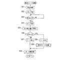
図2はリーク診断全体のメインフローチャートであって、ステップ1では、リーク診断の要求があったか否かを繰り返し判定する。車両停止後、所定時間が経過してリーク診断の要求が発生したときは、ステップ2へ進み、車両の運転開始時の燃料温度と運転終了時点の燃料温度との温度差ΔTが閾値(例えば±1℃)以上であるか否かを判定する。運転中に燃料温度が上昇すれば燃料タンク2内に正圧が発生し、逆に燃料温度が低下すれば燃料タンク2内が負圧化する。 FIG. 2 is a main flowchart of the entire leak diagnosis. In step 1, it is repeatedly determined whether or not there has been a request for leak diagnosis. When a predetermined time has elapsed after the vehicle has stopped and a leak diagnosis request has occurred, the process proceeds to step 2 where the temperature difference ΔT between the fuel temperature at the start of operation of the vehicle and the fuel temperature at the end of operation is a threshold value (for example, ± 1 ° C.) or higher. If the fuel temperature rises during operation, a positive pressure is generated in the
温度差ΔTが±1℃以上であれば、ステップ3へ進み、外気温と燃料温度との相対的な関係が、上記の燃料温度の温度差ΔTを経時的に縮小する方向であるか助長する方向であるかを判別する。つまり、運転中に燃料温度が多少上昇していたと仮定して、車両停止状態における外気温が燃料温度よりも低い場合には、リークと無関係に系内の圧力が低下し得るので、誤診断を防止するために、第1のリーク診断を禁止する。運転中に燃料温度が上昇している場合に、車両停止中の外気温が燃料温度よりも高ければ、温度差ΔTを助長する方向であるので、ステップ4へ進み、燃料タンク2内に存在する正圧を利用する第1のリーク診断を許可する。逆に、運転中に燃料温度が多少低下していたと仮定して、車両停止状態における外気温が燃料温度よりも高い場合には、リークと無関係に系内の圧力が上昇(負圧が減少)し得るので、やはり誤診断を防止するために、第1のリーク診断を禁止する。運転中に燃料温度が低下している場合に、車両停止中の外気温が燃料温度よりも低ければ、温度差ΔTを助長する方向であるので、ステップ4へ進み、燃料タンク2内に存在する負圧を利用した第1のリーク診断を許可する。 If the temperature difference ΔT is ± 1 ° C. or more, the process proceeds to step 3 and promotes whether the relative relationship between the outside air temperature and the fuel temperature is a direction to reduce the temperature difference ΔT of the fuel temperature with time. Determine if the direction. In other words, assuming that the fuel temperature has risen somewhat during operation, if the outside air temperature when the vehicle is stopped is lower than the fuel temperature, the pressure in the system can drop regardless of the leak, so a misdiagnosis is made. In order to prevent this, the first leak diagnosis is prohibited. If the outside air temperature while the vehicle is stopped is higher than the fuel temperature when the fuel temperature is increasing during operation, the temperature difference ΔT is promoted, so the process proceeds to step 4 and exists in the
ステップ2あるいはステップ3でNOの場合は、ステップ5さらにはステップ6へ進み、タンク圧センサ36の検出信号に基づき、燃料タンク2内の圧力が所定レベル以上の正圧であるか否か、所定レベル以上の負圧であるか否か、をそれぞれ判定する。所定レベル以上の正圧もしくは所定レベル以上の負圧でなければ、ステップ7へ進み、加圧用ポンプ27を利用した第2のリーク診断を実行する。 If NO in
ステップ5あるいはステップ6において、燃料タンク2内が所定レベル以上の正圧もしくは所定レベル以上の負圧であると判定した場合には、ステップ8あるいはステップ9へ進み、燃料タンク2内の正圧もしくは負圧による影響を排除するために、第2のリーク診断の実行に先だって、燃料タンク2内の圧力の開放処理を行う。具体的には、ドレンカットバルブ26が開いている状態において、まず第2パージ制御弁32を開弁し、次いで封鎖弁21を開弁して、燃料タンク2内を予めほぼ大気圧とする。そして、このように燃料タンク2内をほぼ大気圧とした上で、ステップ7へ進んで、加圧用ポンプ27を利用した第2のリーク診断を実行する。第2パージ制御弁32は封鎖弁21に比較して通路面積ないし口径が小さいので、上記のように封鎖弁21の開弁前に第2パージ制御弁32を開くことで、圧力開放時の初期の圧力変動が緩慢となり、異音の発生を回避できる。 If it is determined in
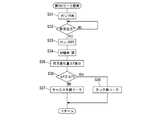
図3は、ステップ4の第1のリーク診断の詳細を示すフローチャートであり、ステップ11において、ドレンカットバルブ26を閉、封鎖弁21を開、第1パージ制御弁23を閉、第2パージ制御弁32を開、とする。つまり系内全体を1つの空間として密閉状態とする。封鎖弁21を開くことによって、燃料タンク2内に存在していた正圧もしくは負圧が系内全体に拡がる。 FIG. 3 is a flowchart showing details of the first leak diagnosis in step 4. In step 11, the drain cut
そして、ステップ12では、系内を密閉した時点での系内圧力をタンク圧センサ36もしくはエバポライン圧センサ37の検出信号から読み込むとともに、所定時間(例えば40分)経過後の系内圧力を再度読み込んで、両者の差つまり所定時間の間の圧力変化量ΔPを求める。ステップ13において、この圧力変化量ΔPを所定の閾値ΔP1と比較し、閾値ΔP1以上の圧力変化(正圧の低下もしくは負圧の減少)がなければ、ステップ14へ進んで、リーク無しと判定する。閾値ΔP1以上の圧力変化があれば、ステップ15へ進んで、リーク有りと判定し、さらに、リークの箇所が燃料タンク2側であるかキャニスタ3側であるかを特定するために、ステップ16へ進んで燃料タンク2側の領域のリーク診断(第3のリーク診断)を実行する。リークの有無を判定した後、最後にステップ17において、封鎖弁21等の各弁を初期状態に復帰させる。 In step 12, the system pressure at the time when the system is sealed is read from the detection signal of the
図4は、ステップ7の第2のリーク診断の詳細を示すフローチャートであり、ステップ21において、ドレンカットバルブ26を閉、封鎖弁21を開、第1パージ制御弁23を閉、第2パージ制御弁32を開、とする。つまり系内全体を1つの空間として密閉状態とする。次に、ステップ22において、加圧用ポンプ27をONとし、系内を加圧する。ステップ23では、系内が診断に必要な所定圧力に達したか否かを判定し、所定圧力に達した段階で、ステップ24へ進んで加圧用ポンプ27をOFFとする。これにより系内全体が加圧状態となる。 FIG. 4 is a flowchart showing details of the second leak diagnosis in
以降は、第1のリーク診断と基本的に同様であり、ステップ25において所定時間(例えば40分)経過後の系内圧力を再度読み込んで、加圧用ポンプ27停止時の所定圧力との差つまり所定時間の間の圧力変化量ΔPを求める。ステップ26において、この圧力変化量ΔPを所定の閾値ΔP2と比較し、閾値ΔP2以上の圧力低下がなければ、ステップ27へ進んで、リーク無しと判定する。閾値ΔP2以上の圧力低下があれば、ステップ28へ進んで、リーク有りと判定し、さらに、リークの箇所が燃料タンク2側であるかキャニスタ3側であるかを特定するために、ステップ29へ進んで燃料タンク2側の領域のリーク診断(第3のリーク診断)を実行する。リークの有無を判定した後、最後にステップ30において、封鎖弁21等の各弁を初期状態に復帰させる。 The subsequent steps are basically the same as the first leak diagnosis. In
なお、図3に示す第1のリーク診断もしくは図4に示す第2のリーク診断の際に、タンク圧センサ36の検出圧力とエバポライン圧センサ37の検出圧力とを互いに比較することで、封鎖弁21の閉固着(開度が小さい異常を含む)の診断が可能である。つまり、封鎖弁21が開いている状態では両者の検出圧力はほぼ等しいはずであるので、両者が所定の許容範囲以上に乖離している場合には、封鎖弁21の閉固着であると判定することができる。 In the first leak diagnosis shown in FIG. 3 or the second leak diagnosis shown in FIG. 4, the detection pressure of the
図5は、ステップ16およびステップ29の第3のリーク診断つまり封鎖弁21よりも燃料タンク2側の領域を対象としたリーク診断のフローチャートである。ステップ31において、加圧用ポンプ27をONとし、系内全体を加圧する。ステップ32では、タンク圧センサ36の検出圧力が診断に必要な所定圧力に達したか否かを判定し、所定圧力に達した段階で、ステップ33,34へ進み、加圧用ポンプ27をOFFとするとともに、封鎖弁21を閉、第2パージ制御弁32を閉、とする。これにより、封鎖弁21で区画される燃料タンク2側の領域が加圧かつ密閉された状態となる。ステップ35において所定時間(例えば40分)経過後の系内圧力を再度読み込んで、加圧用ポンプ27停止時の所定圧力との差つまり所定時間の間の圧力変化量ΔPを求める。ステップ36において、この圧力変化量ΔPを所定の閾値ΔP3と比較し、閾値ΔP3以上の圧力低下がなければ、ステップ37へ進んで、リークの箇所がキャニスタ3側の領域であると判定する。閾値ΔP3以上の圧力低下があれば、ステップ38へ進んで、リークの箇所が燃料タンク2側の領域であると判定する。 FIG. 5 is a flowchart of the third leak diagnosis in
以上、この発明の一実施例を説明したが、この発明は上記実施例に限定されるものではなく、種々の変更が可能である。例えば、上記実施例では加圧用ポンプ27により系内を加圧するようにしているが、減圧用ポンプを用いて減圧することでリーク診断を行うことも可能である。 As mentioned above, although one Example of this invention was described, this invention is not limited to the said Example, A various change is possible. For example, in the above embodiment, the inside of the system is pressurized by the pressurizing
Claims (5)
Translated fromJapanese上記燃料タンクと上記キャニスタとを含む系内を加圧もしくは減圧するポンプと、
系内の圧力を検出する少なくとも1つの圧力センサと、
上記燃料タンクにおける燃料の温度を検出する燃温センサと、
を備え、
リーク診断要求に対し、運転開始時の燃料温度と運転後の燃料温度との温度差に基づき、燃料タンク内に存在する正圧もしくは負圧を用いた第1のリーク診断と、上記ポンプによる強制的な加圧もしくは減圧を用いた第2のリーク診断と、を選択する、蒸発燃料処理装置の診断装置。In an evaporative fuel processing apparatus that adsorbs evaporative fuel generated in a fuel tank at the time of refueling with a canister and introduces it into an intake system of the internal combustion engine for processing during operation of the internal combustion engine.
A pump for pressurizing or depressurizing the system including the fuel tank and the canister;
At least one pressure sensor for detecting pressure in the system;
A fuel temperature sensor for detecting the temperature of the fuel in the fuel tank;
With
In response to the leak diagnosis request, based on the temperature difference between the fuel temperature at the start of operation and the fuel temperature after the operation, the first leak diagnosis using the positive pressure or the negative pressure existing in the fuel tank, and the forced by the pump Apparatus for evaporative fuel treatment, which selects a second leak diagnosis using a normal pressurization or decompression.
上記第1のリーク診断もしくは上記第2のリーク診断によってリークを検出したときに、上記封鎖弁により区画される燃料タンク側の領域のリーク診断、または上記封鎖弁により区画されるキャニスタ側の領域のリーク診断を上記ポンプを用いて行う、請求項1〜3のいずれかに記載の蒸発燃料処理装置の診断装置。A sealing valve provided in an evaporative fuel passage from the fuel tank to the canister;
When a leak is detected by the first leak diagnosis or the second leak diagnosis, the leak diagnosis of the area on the fuel tank side partitioned by the block valve or the area on the canister side partitioned by the block valve The diagnostic apparatus of the evaporative fuel processing apparatus according to claim 1, wherein leak diagnosis is performed using the pump.
上記圧力開放処理は、上記封鎖弁よりも通路面積の小さな電磁弁の開弁により燃料タンク内を大気圧に近付けてから上記封鎖弁を開弁する、請求項3に記載の蒸発燃料処理装置の診断装置。A sealing valve provided in an evaporative fuel passage from the fuel tank to the canister;
The evaporative fuel processing device according to claim 3, wherein the pressure release processing opens the block valve after the inside of the fuel tank is brought close to atmospheric pressure by opening a solenoid valve having a passage area smaller than the block valve. Diagnostic device.
Applications Claiming Priority (1)
| Application Number | Priority Date | Filing Date | Title |
|---|---|---|---|
| PCT/JP2015/067948WO2016207964A1 (en) | 2015-06-23 | 2015-06-23 | Diagnostic device for evaporated fuel processing device |
Publications (2)
| Publication Number | Publication Date |
|---|---|
| JPWO2016207964A1 JPWO2016207964A1 (en) | 2017-10-19 |
| JP6443548B2true JP6443548B2 (en) | 2018-12-26 |
Family
ID=57584863
Family Applications (1)
| Application Number | Title | Priority Date | Filing Date |
|---|---|---|---|
| JP2017524304AExpired - Fee RelatedJP6443548B2 (en) | 2015-06-23 | 2015-06-23 | Evaporative fuel processor diagnostic device |
Country Status (8)
| Country | Link |
|---|---|
| US (1) | US10184430B2 (en) |
| EP (1) | EP3315756B1 (en) |
| JP (1) | JP6443548B2 (en) |
| CN (1) | CN107709745B (en) |
| MX (1) | MX364020B (en) |
| MY (1) | MY167717A (en) |
| RU (1) | RU2666033C1 (en) |
| WO (1) | WO2016207964A1 (en) |
Families Citing this family (16)
| Publication number | Priority date | Publication date | Assignee | Title |
|---|---|---|---|---|
| JP6634997B2 (en)* | 2016-10-07 | 2020-01-22 | 株式会社デンソー | Evaporative fuel processing system |
| JP2018162762A (en)* | 2017-03-27 | 2018-10-18 | 三菱自動車工業株式会社 | Fuel evaporative emission control device |
| CN111094732B (en)* | 2017-09-15 | 2021-11-02 | 三菱自动车工业株式会社 | Fuel Evaporated Gas Emission Suppression Device |
| FR3078747B1 (en) | 2018-03-08 | 2020-02-14 | Continental Automotive France | LEAK DETECTION IN A DEVICE FOR EVAPORATING VAPORS OF A FUEL STORED IN A TANK OF A VEHICLE ENGINE |
| JP2019206959A (en)* | 2018-05-30 | 2019-12-05 | トヨタ自動車株式会社 | Fuel evaporation processing apparatus |
| EP3575587B1 (en) | 2018-05-31 | 2024-05-22 | Stoneridge, Inc. | Evaporative emissions control system leak check module including first and second solenoid valves |
| JP2020056344A (en) | 2018-10-01 | 2020-04-09 | 株式会社デンソー | Evaporated fuel treatment device |
| JP7163723B2 (en)* | 2018-11-06 | 2022-11-01 | 株式会社デンソー | Evaporative fuel processing device |
| CN110031160B (en)* | 2019-05-24 | 2020-06-09 | 安徽江淮汽车集团股份有限公司 | Fuel evaporation leakage detection system and method |
| US11073112B2 (en)* | 2019-07-29 | 2021-07-27 | Nissan North America, Inc. | Evaporative emission control system for a vehicle |
| JP7099638B2 (en)* | 2019-07-30 | 2022-07-12 | 三菱自動車工業株式会社 | Fuel tank system |
| JP7322809B2 (en)* | 2020-05-21 | 2023-08-08 | 株式会社デンソー | Leak hole determination device for evaporated fuel processing device |
| JP7341959B2 (en)* | 2020-08-05 | 2023-09-11 | 愛三工業株式会社 | Evaporated fuel processing equipment |
| DE102020215552A1 (en) | 2020-12-09 | 2022-06-09 | Audi Aktiengesellschaft | Method for operating a fuel tank arrangement for a motor vehicle and corresponding fuel tank arrangement |
| JP7467387B2 (en) | 2021-06-02 | 2024-04-15 | 愛三工業株式会社 | Leak diagnosis device for fuel vapor processing system |
| JP7626046B2 (en) | 2021-12-15 | 2025-02-04 | トヨタ自動車株式会社 | Leak Diagnostic Device |
Family Cites Families (19)
| Publication number | Priority date | Publication date | Assignee | Title |
|---|---|---|---|---|
| US5295472A (en)* | 1992-01-06 | 1994-03-22 | Toyota Jidosha Kabushiki Kaisha | Apparatus for detecting malfunction in evaporated fuel purge system used in internal combustion engine |
| JP3134704B2 (en)* | 1995-02-22 | 2001-02-13 | スズキ株式会社 | Evaporative fuel control system for internal combustion engine |
| JP3277774B2 (en)* | 1995-11-14 | 2002-04-22 | 日産自動車株式会社 | Fault diagnosis device for evaporative fuel evaporation prevention device of internal combustion engine and fuel refueling detection device |
| JPH10104114A (en)* | 1996-09-30 | 1998-04-24 | Nissan Motor Co Ltd | Leak diagnosis device in engine fuel vapor treatment system |
| US6807851B2 (en)* | 2001-07-25 | 2004-10-26 | Denso Corporation | Leak-check apparatus of fuel-vapor-processing system, fuel-temperature estimation apparatus and fuel-temperature-sensor diagnosis apparatus |
| JP4107053B2 (en)* | 2002-11-05 | 2008-06-25 | トヨタ自動車株式会社 | Evaporative fuel processing device for internal combustion engine |
| JP2004346812A (en)* | 2003-05-21 | 2004-12-09 | Honda Motor Co Ltd | Failure determination device for evaporative fuel processing system |
| JP4400312B2 (en)* | 2004-06-01 | 2010-01-20 | 日産自動車株式会社 | Evaporative fuel processor failure detection device |
| JP4815972B2 (en)* | 2005-09-28 | 2011-11-16 | 日産自動車株式会社 | Leak diagnostic device for evaporative fuel processing system |
| JP4715426B2 (en) | 2005-09-28 | 2011-07-06 | 日産自動車株式会社 | Leak diagnostic device for evaporative fuel processing system |
| JP2007177653A (en)* | 2005-12-27 | 2007-07-12 | Toyota Motor Corp | Evaporative fuel processing equipment |
| JP2012149592A (en) | 2011-01-20 | 2012-08-09 | Toyota Motor Corp | Evaporation system leakage diagnostic apparatus |
| JP6251469B2 (en)* | 2012-03-09 | 2017-12-20 | 日産自動車株式会社 | Evaporative fuel processor diagnostic device |
| JP5998529B2 (en)* | 2012-03-09 | 2016-09-28 | 日産自動車株式会社 | Evaporative fuel processor diagnostic device |
| US9026345B2 (en)* | 2012-09-12 | 2015-05-05 | Ford Global Technologies, Llc | Method and system for fuel vapor control |
| JPWO2014061135A1 (en)* | 2012-10-18 | 2016-09-05 | 三菱電機株式会社 | Airtightness diagnostic apparatus and airtightness diagnostic method |
| JP2014156787A (en)* | 2013-02-14 | 2014-08-28 | Denso Corp | Leak diagnosis device for evaporation gas purge system |
| US20150096355A1 (en)* | 2013-10-09 | 2015-04-09 | Aisan Kogyo Kabushiki Kaisha | Failure determination devices for fuel vapor processing systems |
| JP2015075032A (en)* | 2013-10-09 | 2015-04-20 | 愛三工業株式会社 | Failure detection system in evaporable fuel treatment apparatus |
- 2015
- 2015-06-23USUS15/739,020patent/US10184430B2/enactiveActive
- 2015-06-23RURU2017146139Apatent/RU2666033C1/enactive
- 2015-06-23MXMX2017016458Apatent/MX364020B/enactiveIP Right Grant
- 2015-06-23CNCN201580081107.6Apatent/CN107709745B/ennot_activeExpired - Fee Related
- 2015-06-23JPJP2017524304Apatent/JP6443548B2/ennot_activeExpired - Fee Related
- 2015-06-23EPEP15896286.0Apatent/EP3315756B1/enactiveActive
- 2015-06-23MYMYPI2017704895Apatent/MY167717A/enunknown
- 2015-06-23WOPCT/JP2015/067948patent/WO2016207964A1/ennot_activeCeased
Also Published As
| Publication number | Publication date |
|---|---|
| EP3315756A1 (en) | 2018-05-02 |
| US20180171938A1 (en) | 2018-06-21 |
| CN107709745A (en) | 2018-02-16 |
| WO2016207964A1 (en) | 2016-12-29 |
| EP3315756A4 (en) | 2018-05-02 |
| JPWO2016207964A1 (en) | 2017-10-19 |
| MX2017016458A (en) | 2018-05-17 |
| MY167717A (en) | 2018-09-21 |
| CN107709745B (en) | 2018-12-28 |
| MX364020B (en) | 2019-04-11 |
| RU2666033C1 (en) | 2018-09-05 |
| EP3315756B1 (en) | 2022-01-19 |
| US10184430B2 (en) | 2019-01-22 |
Similar Documents
| Publication | Publication Date | Title |
|---|---|---|
| JP6443548B2 (en) | Evaporative fuel processor diagnostic device | |
| JP5998529B2 (en) | Evaporative fuel processor diagnostic device | |
| JP5880159B2 (en) | Evaporative fuel processor diagnostic device | |
| JP6299867B2 (en) | Evaporative fuel processing equipment | |
| JP6287581B2 (en) | Evaporative fuel processing equipment | |
| US9341538B2 (en) | Evaporated fuel processing device and method for diagnosing evaporated fuel processing device | |
| CN105971774B (en) | Evaporated fuel treating apparatus | |
| US9863375B2 (en) | Device and method for diagnosing evaporated fuel processing device | |
| JP6749291B2 (en) | Leak detection device for evaporated fuel processing device | |
| JP6251469B2 (en) | Evaporative fuel processor diagnostic device | |
| JP6380676B2 (en) | Evaporative fuel processing equipment | |
| US9850855B2 (en) | Fuel evaporative gas emission control apparatus | |
| JP2015121113A (en) | Fuel evaporative emission control device | |
| JP3618272B2 (en) | Failure diagnosis device for fuel vapor purge system and fuel vapor purge system |
Legal Events
| Date | Code | Title | Description |
|---|---|---|---|
| A621 | Written request for application examination | Free format text:JAPANESE INTERMEDIATE CODE: A621 Effective date:20170706 | |
| A131 | Notification of reasons for refusal | Free format text:JAPANESE INTERMEDIATE CODE: A131 Effective date:20180605 | |
| TRDD | Decision of grant or rejection written | ||
| A01 | Written decision to grant a patent or to grant a registration (utility model) | Free format text:JAPANESE INTERMEDIATE CODE: A01 Effective date:20181030 | |
| A61 | First payment of annual fees (during grant procedure) | Free format text:JAPANESE INTERMEDIATE CODE: A61 Effective date:20181112 | |
| R151 | Written notification of patent or utility model registration | Ref document number:6443548 Country of ref document:JP Free format text:JAPANESE INTERMEDIATE CODE: R151 | |
| LAPS | Cancellation because of no payment of annual fees |