Movatterモバイル変換


[0]ホーム

URL:


JP6443363B2 - Information terminal device, image forming system, and program - Google Patents

Information terminal device, image forming system, and program
Download PDF

Info

Publication number
JP6443363B2
JP6443363B2JP2016043265AJP2016043265AJP6443363B2JP 6443363 B2JP6443363 B2JP 6443363B2JP 2016043265 AJP2016043265 AJP 2016043265AJP 2016043265 AJP2016043265 AJP 2016043265AJP 6443363 B2JP6443363 B2JP 6443363B2
Authority
JP
Japan
Prior art keywords
image forming
job
setting
terminal device
setting unit
Prior art date
Legal status (The legal status is an assumption and is not a legal conclusion. Google has not performed a legal analysis and makes no representation as to the accuracy of the status listed.)
Expired - Fee Related
Application number
JP2016043265A
Other languages
Japanese (ja)
Other versions
JP2017161980A (en
Inventor
直樹 澤
直樹 澤
Current Assignee (The listed assignees may be inaccurate. Google has not performed a legal analysis and makes no representation or warranty as to the accuracy of the list.)
Kyocera Document Solutions Inc
Original Assignee
Kyocera Document Solutions Inc
Priority date (The priority date is an assumption and is not a legal conclusion. Google has not performed a legal analysis and makes no representation as to the accuracy of the date listed.)
Filing date
Publication date
Application filed by Kyocera Document Solutions IncfiledCriticalKyocera Document Solutions Inc
Priority to JP2016043265ApriorityCriticalpatent/JP6443363B2/en
Publication of JP2017161980ApublicationCriticalpatent/JP2017161980A/en
Application grantedgrantedCritical
Publication of JP6443363B2publicationCriticalpatent/JP6443363B2/en
Expired - Fee Relatedlegal-statusCriticalCurrent
Anticipated expirationlegal-statusCritical

Links

Images

Landscapes

Description

Translated fromJapanese

本発明は、情報端末装置、画像形成システム、及びプログラムに関する。  The present invention relates to an information terminal device, an image forming system, and a program.

画像形成装置に対して複数のジョブの実行条件を並行して設定する技術が知られている。例えば、特許文献1には、複数のプレビュー画像を表示する画像形成装置が開示されている。具体的には、画像形成装置は、各プレビュー画像に対応する印刷条件の設定内容を変更し、設定内容が変更された場合には、対応するプレビュー画像を、変更された設定内容に応じたプレビュー画像に変更する。  A technique is known in which execution conditions for a plurality of jobs are set in parallel for an image forming apparatus. For example,Patent Document 1 discloses an image forming apparatus that displays a plurality of preview images. Specifically, the image forming apparatus changes the setting contents of the printing conditions corresponding to each preview image, and when the setting contents are changed, the corresponding preview image is previewed according to the changed setting contents. Change to an image.

特許文献1に記載の画像形成装置によれば、複数の印刷条件の設定を並行して行うことができる。  According to the image forming apparatus described inPatent Document 1, a plurality of printing conditions can be set in parallel.

特開2008−304709号公報JP 2008-304709 A

しかしながら、特許文献1に記載の画像形成装置では、画像形成装置の備えるディスプレーのサイズが小さい場合には、複数の印刷条件をユーザーが所望する大きさで表示できない場合がある。したがって、ユーザーが適正な印刷条件を設定できない可能性がある。  However, in the image forming apparatus described inPatent Document 1, when the display size of the image forming apparatus is small, a plurality of printing conditions may not be displayed in a size desired by the user. Therefore, there is a possibility that the user cannot set proper printing conditions.

本発明は、上記課題に鑑みてなされたものであり、複数のジョブの実行条件を並行して設定できる情報端末装置、画像形成システム、及びプログラムを提供することを目的としている。  SUMMARY An advantage of some aspects of the invention is that it provides an information terminal device, an image forming system, and a program that can set execution conditions for a plurality of jobs in parallel.

本発明の情報端末装置は、画像形成装置と通信する情報端末装置であって、ディスプレー、方向検出部、第1設定部、及び第2設定部を備える。前記方向検出部は、前記ディスプレーの方向を検出する。前記第1設定部は、前記方向検出部が第1方向を検出している場合に、第1ジョブの設定を前記画像形成装置に対して行う。前記第2設定部は、前記方向検出部が前記第1方向と相違する第2方向を検出している場合に、前記第1ジョブと相違する第2ジョブの設定を前記画像形成装置に対して行う。  An information terminal apparatus according to the present invention is an information terminal apparatus that communicates with an image forming apparatus, and includes a display, a direction detection unit, a first setting unit, and a second setting unit. The direction detection unit detects the direction of the display. The first setting unit sets a first job to the image forming apparatus when the direction detection unit detects the first direction. The second setting unit sets a second job setting different from the first job to the image forming apparatus when the direction detection unit detects a second direction different from the first direction. Do.

本発明の画像形成システムは、ディスプレーを備えた情報端末装置と、前記情報端末装置とする画像形成装置とを備える。前記情報端末装置は、方向検出部、第1設定部、及び第2設定部を備える。前記方向検出部は、前記ディスプレーの方向を検出する。前記第1設定部は、前記方向検出部が第1方向を検出している場合に、第1ジョブの設定を前記画像形成装置に対して行う。前記第2設定部は、前記方向検出部が前記第1方向と相違する第2方向を検出している場合に、前記第1ジョブと相違する第2ジョブの設定を前記画像形成装置に対して行う。前記画像形成装置は、指示受付部、及びジョブ制御部を備える。前記指示受付部は、前記情報端末装置からの指示を受け付ける。前記ジョブ制御部は、前記指示受付部が受け付けた指示に従って前記第1ジョブ及び前記第2ジョブの設定を行う。  The image forming system of the present invention includes an information terminal device provided with a display, and an image forming device serving as the information terminal device. The information terminal device includes a direction detection unit, a first setting unit, and a second setting unit. The direction detection unit detects the direction of the display. The first setting unit sets a first job to the image forming apparatus when the direction detection unit detects the first direction. The second setting unit sets a second job setting different from the first job to the image forming apparatus when the direction detection unit detects a second direction different from the first direction. Do. The image forming apparatus includes an instruction receiving unit and a job control unit. The instruction receiving unit receives an instruction from the information terminal device. The job control unit sets the first job and the second job in accordance with an instruction received by the instruction receiving unit.

本発明のプログラムは、情報端末装置に記憶されるプログラムであって、前記情報端末装置は、ディスプレーとコンピューターとを備え、画像形成装置と通信する。前記プログラムは、前記コンピューターを方向検出部、第1設定部、及び第2設定部として機能させる。前記方向検出部は、前記ディスプレーの方向を検出する。前記第1設定部は、前記方向検出部が第1方向を検出している場合に、第1ジョブの設定を前記画像形成装置に対して行う。前記第2設定部は、前記方向検出部が前記第1方向と相違する第2方向を検出している場合に、前記第1ジョブと相違する第2ジョブの設定を前記画像形成装置に対して行う。  The program of the present invention is a program stored in an information terminal device, and the information terminal device includes a display and a computer and communicates with the image forming apparatus. The program causes the computer to function as a direction detection unit, a first setting unit, and a second setting unit. The direction detection unit detects the direction of the display. The first setting unit sets a first job to the image forming apparatus when the direction detection unit detects the first direction. The second setting unit sets a second job setting different from the first job to the image forming apparatus when the direction detection unit detects a second direction different from the first direction. Do.

本発明の情報端末装置、画像形成システム、及びプログラムによれば、複数のジョブの実行条件を並行して設定できる。  According to the information terminal device, the image forming system, and the program of the present invention, execution conditions for a plurality of jobs can be set in parallel.

本発明の実施形態に係る画像形成システムの全体構成を示す図である。1 is a diagram illustrating an overall configuration of an image forming system according to an embodiment of the present invention.画像形成装置の構成を示す図である。1 is a diagram illustrating a configuration of an image forming apparatus.タブレット端末装置の制御部及び画像形成装置の制御部の構成を示す図である。It is a figure which shows the structure of the control part of a tablet terminal device, and the control part of an image forming apparatus.方向検出部が第1方向を検出している場合にディスプレーに表示されるプレビュー画像の一例を示す図である。It is a figure which shows an example of the preview image displayed on a display, when the direction detection part is detecting the 1st direction.方向検出部が第2方向を検出している場合にディスプレーに表示されるプレビュー画像の一例を示す図である。It is a figure which shows an example of the preview image displayed on a display, when the direction detection part is detecting the 2nd direction.方向検出部が第3方向を検出している場合にディスプレーに表示されるプレビュー画像の一例を示す図である。It is a figure which shows an example of the preview image displayed on a display, when the direction detection part is detecting the 3rd direction.方向検出部が第3方向を検出している場にディスプレーに表示されるプレビュー画像の他の一例を示す図である。It is a figure which shows another example of the preview image displayed on a display when the direction detection part is detecting the 3rd direction.方向検出部が第3方向を検出している場合にディスプレーに表示されるプレビュー画像の更に他の一例を示す図である。It is a figure which shows another example of the preview image displayed on a display, when the direction detection part is detecting the 3rd direction.タブレット端末装置の制御部の動作を示すフローチャートである。It is a flowchart which shows operation | movement of the control part of a tablet terminal device.タブレット端末装置の制御部の画像表示処理を示すフローチャートである。It is a flowchart which shows the image display process of the control part of a tablet terminal device.

以下、本発明の実施形態について、図面(図1〜図10)を参照しながら説明する。なお、図中、同一又は相当部分については同一の参照符号を付して説明を繰り返さない。  Embodiments of the present invention will be described below with reference to the drawings (FIGS. 1 to 10). In the drawings, the same or corresponding parts are denoted by the same reference numerals and description thereof is not repeated.

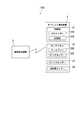
まず、図1を参照して本発明の実施形態に係る画像形成システム100について説明する。図1は、本発明の実施形態に係る画像形成システム100の全体構成を示す。図1に示すように、画像形成システム100は、タブレット端末装置1及び画像形成装置2を備える。タブレット端末装置1は、画像形成装置2と通信する。具体的には、タブレット端末装置1は、画像形成装置2と、例えば、Wi−Fi、Bluetooth(登録商標)のような無線通信を介して通信する。タブレット端末装置1は、「情報端末装置」の一例に相当する。  First, animage forming system 100 according to an embodiment of the present invention will be described with reference to FIG. FIG. 1 shows the overall configuration of animage forming system 100 according to an embodiment of the present invention. As shown in FIG. 1, theimage forming system 100 includes atablet terminal device 1 and animage forming device 2. Thetablet terminal device 1 communicates with theimage forming device 2. Specifically, thetablet terminal device 1 communicates with theimage forming device 2 via wireless communication such as Wi-Fi or Bluetooth (registered trademark). Thetablet terminal device 1 corresponds to an example of an “information terminal device”.

タブレット端末装置1は、制御部11、タッチパネル12、ジャイロセンサー13及び加速度センサー14を備える。タブレット端末装置1は、例えばタブレットPC(Personal Computer)である。制御部11は、タブレット端末装置1の動作を制御する。制御部11は、プロセッサー11A、及び記憶部11Bを備える。記憶部11Bには制御プログラムが記憶されている。プロセッサー11Aは、記憶部11Bに記憶された制御プログラムを読み出して実行することによってタブレット端末装置1の動作を制御する。  Thetablet terminal device 1 includes acontrol unit 11, atouch panel 12, agyro sensor 13, and anacceleration sensor 14. Thetablet terminal device 1 is, for example, a tablet PC (Personal Computer). Thecontrol unit 11 controls the operation of thetablet terminal device 1. Thecontrol unit 11 includes aprocessor 11A and astorage unit 11B. A control program is stored in thestorage unit 11B. Theprocessor 11A controls the operation of thetablet terminal device 1 by reading and executing the control program stored in thestorage unit 11B.

タッチパネル12は、ディスプレー12A及びタッチセンサー12Bを備える。ディスプレー12Aは、種々の画像を表示する。タッチセンサー12Bはタッチパネル12への物体の接触位置を検出する。タッチセンサー12Bは、例えばディスプレー12Aの表示面上に配置される。  Thetouch panel 12 includes adisplay 12A and atouch sensor 12B. Thedisplay 12A displays various images. Thetouch sensor 12 </ b> B detects the contact position of the object with thetouch panel 12. Thetouch sensor 12B is disposed on the display surface of thedisplay 12A, for example.

ジャイロセンサー13は、タブレット端末装置1の3軸方向の傾きを検出する。「3軸方向」とは、タブレット端末装置1の基準方向と、基準方向に直交する2方向とを示す。具体的には、基準方向は、例えば、ディスプレー12Aの表示面の4辺のうちの長辺方向を示す。基準方向に直交する2方向は、ディスプレー12Aの表示面の4辺のうちの短辺方向と、ディスプレー12Aの表示面と直交する方向とを示す。ジャイロセンサー13は、「方向検出部」の一部を構成する。  Thegyro sensor 13 detects the inclination of thetablet terminal device 1 in the three axis directions. “Triaxial direction” indicates a reference direction of thetablet terminal device 1 and two directions orthogonal to the reference direction. Specifically, the reference direction indicates, for example, the long side direction of the four sides of the display surface of thedisplay 12A. The two directions orthogonal to the reference direction indicate the short side direction of the four sides of the display surface of thedisplay 12A and the direction orthogonal to the display surface of thedisplay 12A. Thegyro sensor 13 constitutes a part of the “direction detection unit”.

加速度センサー14は、タブレット端末装置1の3軸方向の傾きを検出する。「3軸方向」とは、ジャイロセンサー13の「3軸方向」と同一の方向を示す。加速度センサー14は、「振動検出部」の一部を構成する。  Theacceleration sensor 14 detects the inclination of thetablet terminal device 1 in the three-axis direction. The “triaxial direction” indicates the same direction as the “triaxial direction” of thegyro sensor 13. Theacceleration sensor 14 constitutes a part of a “vibration detector”.

次に、図2を参照して画像形成装置2について説明する。図2は、画像形成装置2の構成を示す。図2に示すように、画像形成装置2は、複合機である。また、画像形成装置2は、画像形成ユニット21、画像読取ユニット22、原稿搬送ユニット23、操作パネル24及び制御部25を備える。  Next, theimage forming apparatus 2 will be described with reference to FIG. FIG. 2 shows the configuration of theimage forming apparatus 2. As shown in FIG. 2, theimage forming apparatus 2 is a multifunction machine. Further, theimage forming apparatus 2 includes animage forming unit 21, animage reading unit 22, adocument transport unit 23, anoperation panel 24, and acontrol unit 25.

画像形成ユニット21は、記録媒体の一例である用紙Pに画像を形成する。画像読取ユニット22は、原稿Rに形成された画像を読み取る。原稿搬送ユニット23は、原稿Rを画像読取ユニット22に供給する。操作パネル24は、タッチパネル241を備え、ユーザーからの操作を受け付ける。制御部25は、画像形成装置2の動作を制御する。  Theimage forming unit 21 forms an image on a sheet P that is an example of a recording medium. Theimage reading unit 22 reads an image formed on the document R. Thedocument transport unit 23 supplies the document R to theimage reading unit 22. Theoperation panel 24 includes atouch panel 241 and receives an operation from a user. Thecontrol unit 25 controls the operation of theimage forming apparatus 2.

また、画像形成ユニット21は、給紙カセット211、搬送ローラー対212、画像形成部213、定着器214、排出ローラー対215、及び排出トレイ216を備える。  Further, theimage forming unit 21 includes apaper feed cassette 211, atransport roller pair 212, animage forming unit 213, a fixingdevice 214, adischarge roller pair 215, and adischarge tray 216.

給紙カセット211から繰り出された用紙Pは、搬送ローラー対212によって画像形成部213まで搬送される。画像形成部213は、用紙Pに画像を形成する。画像が形成された用紙Pは、定着器214まで搬送される。定着器214は、用紙Pに形成された画像を用紙Pに定着する。画像が定着された用紙Pは、排出ローラー対215によって排出トレイ216へ排出される。  The paper P fed out from thepaper feed cassette 211 is transported to theimage forming unit 213 by thetransport roller pair 212. Theimage forming unit 213 forms an image on the paper P. The paper P on which the image is formed is conveyed to thefixing device 214. The fixingdevice 214 fixes the image formed on the paper P onto the paper P. The paper P on which the image is fixed is discharged to thedischarge tray 216 by thedischarge roller pair 215.

制御部25は、プロセッサー25A、及び記憶部25Bを備える。記憶部25Bには制御プログラムが記憶されている。プロセッサー25Aは、記憶部25Bに記憶された制御プログラムを読み出して実行することによって画像形成装置2の動作を制御する。  Thecontrol unit 25 includes aprocessor 25A and astorage unit 25B. A control program is stored in thestorage unit 25B. Theprocessor 25A controls the operation of theimage forming apparatus 2 by reading and executing the control program stored in thestorage unit 25B.

次に、図3を参照してタブレット端末装置1の制御部11及び画像形成装置2の制御部25の構成について説明する。図3は、タブレット端末装置1の制御部11及び画像形成装置2の制御部25の構成を示す。図3に示すように、制御部11は、方向検出部111、第1設定部112、第2設定部113、振動検出部114及び実行指示部115を備える。具体的には、プロセッサー11Aは、記憶部11Bに記憶された制御プログラムを読み出して実行することによって、方向検出部111、第1設定部112、第2設定部113、振動検出部114及び実行指示部115として機能する。  Next, the configuration of thecontrol unit 11 of thetablet terminal device 1 and thecontrol unit 25 of theimage forming apparatus 2 will be described with reference to FIG. FIG. 3 shows a configuration of thecontrol unit 11 of thetablet terminal device 1 and thecontrol unit 25 of theimage forming apparatus 2. As illustrated in FIG. 3, thecontrol unit 11 includes adirection detection unit 111, afirst setting unit 112, asecond setting unit 113, avibration detection unit 114, and anexecution instruction unit 115. Specifically, theprocessor 11A reads and executes the control program stored in thestorage unit 11B, thereby executing thedirection detection unit 111, thefirst setting unit 112, thesecond setting unit 113, thevibration detection unit 114, and the execution instruction. It functions as theunit 115.

方向検出部111は、ジャイロセンサー13の検出結果に基づいてディスプレー12Aの方向DRを検出する。  Thedirection detection unit 111 detects the direction DR of thedisplay 12 </ b> A based on the detection result of thegyro sensor 13.

第1設定部112は、方向検出部111が第1方向DR1を検出している場合に、第1ジョブJB1の実行条件の設定を画像形成装置2に対して行う。本実施形態では、第1ジョブJB1は、例えば1つの画像の印刷ジョブである。  Thefirst setting unit 112 sets the execution condition of the first job JB1 for theimage forming apparatus 2 when thedirection detection unit 111 detects the first direction DR1. In the present embodiment, the first job JB1 is, for example, a print job for one image.

第2設定部113は、方向検出部111が第1方向DR1と相違する第2方向DR2を検出している場合に、第2ジョブJB2の実行条件の設定を画像形成装置2に対して行う。第2方向DR2は、例えば、第1方向DR1と逆方向である。本実施形態では、第2ジョブJB2は、例えば1つの画像の印刷ジョブである。  Thesecond setting unit 113 sets an execution condition for the second job JB2 in theimage forming apparatus 2 when thedirection detection unit 111 detects a second direction DR2 that is different from the first direction DR1. The second direction DR2 is, for example, the opposite direction to the first direction DR1. In the present embodiment, the second job JB2 is, for example, a print job for one image.

振動検出部114は、加速度センサー14を介して、タブレット端末装置1の振動を検出する。  Thevibration detection unit 114 detects vibration of thetablet terminal device 1 via theacceleration sensor 14.

実行指示部115は、ユーザーからの入力に基づいて、第1ジョブJB1及び第2ジョブJB2の少なくとも一方の実行を画像形成装置2に対して指示する。  Theexecution instruction unit 115 instructs theimage forming apparatus 2 to execute at least one of the first job JB1 and the second job JB2 based on an input from the user.

図3に示すように、制御部25は、指示受付部251及びジョブ制御部252を備える。具体的には、プロセッサー25Aは、記憶部25Bに記憶された制御プログラムを読み出して実行することによって、指示受付部251及びジョブ制御部252として機能する。  As shown in FIG. 3, thecontrol unit 25 includes aninstruction receiving unit 251 and ajob control unit 252. Specifically, theprocessor 25A functions as aninstruction receiving unit 251 and ajob control unit 252 by reading and executing a control program stored in thestorage unit 25B.

指示受付部251は、タブレット端末装置1からの指示を受け付ける。ジョブ制御部252は、指示受付部251が受け付けたタブレット端末装置1からの指示に従ってジョブの設定及びジョブの実行を行う。  Theinstruction receiving unit 251 receives an instruction from thetablet terminal device 1. Thejob control unit 252 performs job setting and job execution in accordance with the instruction from thetablet terminal device 1 received by theinstruction receiving unit 251.

次に、図3〜図8を参照して、方向検出部111、第1設定部112及び第2設定部113の機能について説明する。まず、図3及び図4を参照して、方向検出部111及び第1設定部112について説明する。本実施形態では、便宜上、ディスプレー12Aが所定平面内で回転される場合について説明する。例えば、ディスプレー12Aの長辺方向が基準方向と一致する場合に、方向検出部111は、ディスプレー12Aの方向DRとして第1方向DR1を検出する。また、方向検出部111は、ディスプレー12Aの方向DRと第1方向DR1とのなす角度θを検出する。  Next, functions of thedirection detection unit 111, thefirst setting unit 112, and thesecond setting unit 113 will be described with reference to FIGS. First, thedirection detection unit 111 and thefirst setting unit 112 will be described with reference to FIGS. 3 and 4. In this embodiment, the case where thedisplay 12A is rotated within a predetermined plane will be described for convenience. For example, when the long side direction of thedisplay 12A coincides with the reference direction, thedirection detection unit 111 detects the first direction DR1 as the direction DR of thedisplay 12A. Further, thedirection detection unit 111 detects an angle θ formed by the direction DR of thedisplay 12A and the first direction DR1.

図4は、方向検出部111が第1方向DR1を検出している場合にディスプレー12Aに表示される第1プレビュー画像PV1の一例を示す。図4に示すように、第1方向DR1は、例えば、ディスプレー12Aの表示面の4辺のうちの長辺に略平行な方向を示す。  FIG. 4 shows an example of the first preview image PV1 displayed on thedisplay 12A when thedirection detection unit 111 detects the first direction DR1. As shown in FIG. 4, the first direction DR1 indicates a direction substantially parallel to the long side of the four sides of the display surface of thedisplay 12A, for example.

方向検出部111が第1方向DR1を検出している場合に、第1設定部112は、1つの画像の第1印刷条件C1を画像形成装置2に対して設定する。具体的には、第1設定部112は、ディスプレー12Aに図略の第1設定画面SC1を表示して、ユーザーからの入力に基づいて第1印刷条件C1を画像形成装置2に対して設定する。また、第1設定部112は、例えば、第1設定画面SC1に表示されたプレビューボタンPVBがタッチされた場合に、図4に示すように、第1印刷条件C1に対応する第1プレビュー画像PV1をディスプレー12Aに表示する。  When thedirection detection unit 111 detects the first direction DR1, thefirst setting unit 112 sets the first printing condition C1 of one image for theimage forming apparatus 2. Specifically, thefirst setting unit 112 displays a first setting screen SC1 (not shown) on thedisplay 12A, and sets the first printing condition C1 for theimage forming apparatus 2 based on an input from the user. . Further, thefirst setting unit 112, for example, when the preview button PVB displayed on the first setting screen SC1 is touched, as shown in FIG. 4, the first preview image PV1 corresponding to the first printing condition C1. Is displayed on thedisplay 12A.

次に、図3及び図5を参照して、方向検出部111及び第2設定部113について説明する。図5は、方向検出部111が第2方向DR2を検出している場合にディスプレー12Aに表示される第2プレビュー画像PV2の一例を示す。図5に示すように、本実施形態では、第2方向DR2は、第1方向DR1と逆方向である。第2方向DR2と第1方向DR1とのなす角度は、180°である。  Next, thedirection detection unit 111 and thesecond setting unit 113 will be described with reference to FIGS. 3 and 5. FIG. 5 shows an example of the second preview image PV2 displayed on thedisplay 12A when thedirection detection unit 111 detects the second direction DR2. As shown in FIG. 5, in the present embodiment, the second direction DR2 is opposite to the first direction DR1. The angle formed by the second direction DR2 and the first direction DR1 is 180 °.

方向検出部111が第2方向DR2を検出している場合に、第2設定部113は、1つの画像の第2印刷条件C2を画像形成装置2に対して設定する。第2印刷条件C2は、第1印刷条件C1とは相違する。第2設定部113は、ディスプレー12Aに図略の第2設定画面SC2を表示して、ユーザーからの入力に基づいて第2印刷条件C2を画像形成装置2に対して設定する。また、第2設定部113は、例えば、図略の設定画面に表示されたプレビューボタンPVBがタッチされた場合に、図5に示すように、第2印刷条件C2に対応する第2プレビュー画像PV2をディスプレー12Aに表示する。  When thedirection detection unit 111 detects the second direction DR2, thesecond setting unit 113 sets the second printing condition C2 for one image for theimage forming apparatus 2. The second printing condition C2 is different from the first printing condition C1. Thesecond setting unit 113 displays a second setting screen SC2 (not shown) on thedisplay 12A, and sets the second printing condition C2 for theimage forming apparatus 2 based on the input from the user. In addition, for example, when the preview button PVB displayed on the setting screen (not shown) is touched, thesecond setting unit 113 displays the second preview image PV2 corresponding to the second printing condition C2, as shown in FIG. Is displayed on thedisplay 12A.

第2印刷条件C2は、第1印刷条件C1と、例えば印刷濃度が異なる。第2印刷条件C2の印刷濃度は、第1印刷条件C1の印刷濃度よりも濃い。よって、第2プレビュー画像PV2は、第1プレビュー画像PV1よりも濃い。第2プレビュー画像PV2が第1プレビュー画像PV1よりも濃いことを、第2プレビュー画像PV2の人物の髪にハッチングを施し、第1プレビュー画像PV1の人物の髪にハッチングを施さないことによって図示している。  The second printing condition C2 is different from the first printing condition C1, for example, in print density. The printing density of the second printing condition C2 is higher than the printing density of the first printing condition C1. Therefore, the second preview image PV2 is darker than the first preview image PV1. The fact that the second preview image PV2 is darker than the first preview image PV1 is illustrated by hatching the human hair of the second preview image PV2 and not hatching the human hair of the first preview image PV1. Yes.

以上、図3〜図5を参照して説明したように、方向検出部111が第1方向DR1を検出している場合に、第1設定部112は第1ジョブJB1の実行条件の設定を画像形成装置2に対して行う。また、方向検出部111が第1方向DR1と相違する第2方向DR2を検出している場合に、第2設定部113は、第2ジョブJB2の実行条件の設定を画像形成装置2に対して行う。よって、ユーザーは方向検出部111が第1方向DR1を検出するようにタブレット端末装置1を配置することによって、第1ジョブJB1の実行条件の設定を画像形成装置2に対して行うことができる。また、ユーザーは方向検出部111が第2方向DR2を検出するようにタブレット端末装置1を配置することによって、第2ジョブJB2の実行条件の設定を画像形成装置2に対して行うことができる。したがって、複数のジョブJB1、JB2の実行条件を並行して設定できる。  As described above with reference to FIGS. 3 to 5, when thedirection detection unit 111 detects the first direction DR1, thefirst setting unit 112 sets the execution condition of the first job JB1 as an image. This is performed on the formingapparatus 2. When thedirection detection unit 111 detects a second direction DR2 that is different from the first direction DR1, thesecond setting unit 113 sets the execution condition of the second job JB2 to theimage forming apparatus 2. Do. Therefore, the user can set the execution condition of the first job JB1 to theimage forming apparatus 2 by arranging thetablet terminal device 1 so that thedirection detection unit 111 detects the first direction DR1. Further, the user can set the execution condition of the second job JB2 to theimage forming apparatus 2 by arranging thetablet terminal device 1 so that thedirection detection unit 111 detects the second direction DR2. Therefore, the execution conditions for the plurality of jobs JB1 and JB2 can be set in parallel.

また、第2方向DR2は、第1方向DR1と反対の方向である。よって、ユーザーは方向検出部111が第1方向DR1又は第2方向DR2を検出するようにタブレット端末装置1を容易に配置することができる。したがって、ユーザーは、第1ジョブJB1の実行条件の設定と、第2ジョブJB2の実行条件の設定とを容易に切り換えることができる。  The second direction DR2 is the opposite direction to the first direction DR1. Therefore, the user can easily arrange thetablet terminal device 1 so that thedirection detection unit 111 detects the first direction DR1 or the second direction DR2. Therefore, the user can easily switch between setting the execution condition of the first job JB1 and setting the execution condition of the second job JB2.

更に、第1設定部112は、ディスプレー12Aに第1設定画面SC1を表示する。そして、第1設定画面SC1に対するユーザーからの入力に基づいて第1ジョブJB1を画像形成装置2に対して設定する。一方、第2設定部113は、ディスプレー12Aに第2設定画面SC2を表示する。そして、第2設定画面SC2に対するユーザーからの入力に基づいて第2ジョブJB2を画像形成装置2に対して設定する。よって、ユーザーは、第1設定画面SC1を介して第1ジョブJB1の実行条件の画像形成装置2に対する設定を行うことができる。また、第2設定画面SC2を介して第2ジョブJB2の実行条件の画像形成装置2に対する設定を行うことができる。したがって、画像形成装置2に対して第1ジョブJB1及び第2ジョブJB2の実行条件を並行して容易に設定することができる。  Further, thefirst setting unit 112 displays a first setting screen SC1 on thedisplay 12A. Then, the first job JB1 is set for theimage forming apparatus 2 based on the input from the user to the first setting screen SC1. On the other hand, thesecond setting unit 113 displays a second setting screen SC2 on thedisplay 12A. Then, the second job JB2 is set for theimage forming apparatus 2 based on the input from the user to the second setting screen SC2. Therefore, the user can set the execution conditions for the first job JB1 for theimage forming apparatus 2 via the first setting screen SC1. Further, the execution conditions for the second job JB2 can be set for theimage forming apparatus 2 via the second setting screen SC2. Therefore, the execution conditions of the first job JB1 and the second job JB2 can be easily set in parallel to theimage forming apparatus 2.

加えて、第1ジョブJB1及び第2ジョブJB2は、画像の印刷ジョブである。また、第1設定部112は、画像の第1印刷条件C1を画像形成装置2に対して設定する。第1設定部112は、第1印刷条件C1に対応する第1プレビュー画像PV1をディスプレー12Aに表示する。一方、第2設定部113は、画像の第2印刷条件C2を画像形成装置2に対して設定する。第2印刷条件C2は、第1印刷条件C1とは相違する。第2設定部113は、第2印刷条件C2に対応する第2プレビュー画像PV2をディスプレー12Aに表示する。したがって、ユーザーは、第1プレビュー画像PV1を参照して第1印刷条件C1を所望する条件に設定すると共に、第2プレビュー画像PV2を参照して第2印刷条件C2を所望する条件に設定することができる。  In addition, the first job JB1 and the second job JB2 are image print jobs. Thefirst setting unit 112 sets the first print condition C1 for the image to theimage forming apparatus 2. Thefirst setting unit 112 displays the first preview image PV1 corresponding to the first printing condition C1 on thedisplay 12A. On the other hand, thesecond setting unit 113 sets the second print condition C2 for the image to theimage forming apparatus 2. The second printing condition C2 is different from the first printing condition C1. Thesecond setting unit 113 displays the second preview image PV2 corresponding to the second printing condition C2 on thedisplay 12A. Therefore, the user refers to the first preview image PV1 and sets the first printing condition C1 to a desired condition, and refers to the second preview image PV2 to set the second printing condition C2 to a desired condition. Can do.

次に、図3及び図6〜図8を参照して、方向検出部111、第1設定部112及び第2設定部113の機能について説明する。まず、図3及び図6を参照して方向検出部111、第1設定部112及び第2設定部113の機能について説明する。図6は、方向検出部111が第3方向DR3を検出している場合にディスプレー12Aに表示されるプレビュー画像PV1、PV2の一例を示す。  Next, functions of thedirection detection unit 111, thefirst setting unit 112, and thesecond setting unit 113 will be described with reference to FIG. 3 and FIGS. First, functions of thedirection detection unit 111, thefirst setting unit 112, and thesecond setting unit 113 will be described with reference to FIGS. FIG. 6 shows an example of preview images PV1 and PV2 displayed on thedisplay 12A when thedirection detection unit 111 detects the third direction DR3.

方向検出部111が第1方向DR1と第2方向DR2との間の第3方向DR3を検出している場合に、第1設定部112及び第2設定部113は、以下の処理を実行する。すなわち、第1設定部112はディスプレー12Aの第1領域R1に第1プレビュー画像PV1を表示する。第2設定部113はディスプレー12Aの第2領域R2に第2プレビュー画像PV2を表示する。第2領域R2は第1領域R1と相違する。  When thedirection detection unit 111 detects the third direction DR3 between the first direction DR1 and the second direction DR2, thefirst setting unit 112 and thesecond setting unit 113 perform the following processing. That is, thefirst setting unit 112 displays the first preview image PV1 in the first region R1 of thedisplay 12A. Thesecond setting unit 113 displays the second preview image PV2 in the second region R2 of thedisplay 12A. The second region R2 is different from the first region R1.

また、方向検出部111が第3方向DR3を検出している場合に、第1設定部112及び第2設定部113は、更に以下の処理を実行する。第1設定部112は、第1方向DR1と第3方向DR3とのなす角度θ1に応じて、第1領域R1のサイズを定める。第2設定部113は、第2方向DR2と第3方向DR3とのなす角度θ2に応じて、第2領域R2のサイズを定める。具体的には、第1設定部112は、角度θ1の大きさに応じて、第1領域R1のサイズを定める。第2設定部113は、角度θ2の大きさに応じて、第2領域R2のサイズを定める。更に、具体的には、第1設定部112は、角度θ1が小さい程、第1領域R1のサイズを大きく定める。第2設定部113は、角度θ2が小さい程、第2領域R2のサイズを大きく定める。  When thedirection detection unit 111 detects the third direction DR3, thefirst setting unit 112 and thesecond setting unit 113 further execute the following process. Thefirst setting unit 112 determines the size of the first region R1 according to the angle θ1 formed by the first direction DR1 and the third direction DR3. Thesecond setting unit 113 determines the size of the second region R2 according to the angle θ2 formed by the second direction DR2 and the third direction DR3. Specifically, thefirst setting unit 112 determines the size of the first region R1 according to the size of the angle θ1. Thesecond setting unit 113 determines the size of the second region R2 according to the size of the angle θ2. More specifically, thefirst setting unit 112 determines the size of the first region R1 to be larger as the angle θ1 is smaller. Thesecond setting unit 113 determines the size of the second region R2 to be larger as the angle θ2 is smaller.

方向検出部111が第3方向DR3を検出している。また、角度θ1の大きさは、角度θ2の大きさと同一である。よって、第1設定部112及び第2設定部113は、第1領域R1のサイズと第2領域R2のサイズとを同一に定める。したがって、図6に示すように、ディスプレー12Aに同一サイズの第1領域R1及び第2領域R2が表示される。また、第1領域R1には、第1設定部112が第1プレビュー画像PV1を表示し、第2領域R2には、第2設定部113が第2プレビュー画像PV2を表示している。  Thedirection detection unit 111 detects the third direction DR3. The size of the angle θ1 is the same as the size of the angle θ2. Therefore, thefirst setting unit 112 and thesecond setting unit 113 determine the size of the first region R1 and the size of the second region R2 to be the same. Therefore, as shown in FIG. 6, the first area R1 and the second area R2 having the same size are displayed on thedisplay 12A. Further, thefirst setting unit 112 displays the first preview image PV1 in the first region R1, and thesecond setting unit 113 displays the second preview image PV2 in the second region R2.

次に、図3及び図7を参照して第1設定部112及び第2設定部113の機能について説明する。図7は、方向検出部111が第3方向DR3を検出している場合にディスプレー12Aに表示されるプレビュー画像PV1、PV2の他の一例を示す。図7に示す第3方向DR3は、角度θ1が角度θ2よりも小さい点で図6に示す第3方向DR3と相違する。  Next, functions of thefirst setting unit 112 and thesecond setting unit 113 will be described with reference to FIGS. 3 and 7. FIG. 7 shows another example of preview images PV1 and PV2 displayed on thedisplay 12A when thedirection detection unit 111 detects the third direction DR3. The third direction DR3 shown in FIG. 7 is different from the third direction DR3 shown in FIG. 6 in that the angle θ1 is smaller than the angle θ2.

図7に示すように、方向検出部111が第3方向DR3を検出している。また、角度θ1が角度θ2よりも小さいため、第1領域R1及び第2領域R2が第1領域R1のサイズを第2領域R2のサイズより大きく定める。したがって、ディスプレー12Aに第2領域R2より大きく第1領域R1が表示される。また、第1領域R1には、第1設定部112が第1プレビュー画像PV1を表示し、第2領域R2には、第2設定部113が第2プレビュー画像PV2を表示している。  As shown in FIG. 7, thedirection detecting unit 111 detects the third direction DR3. Further, since the angle θ1 is smaller than the angle θ2, the first region R1 and the second region R2 determine the size of the first region R1 larger than the size of the second region R2. Accordingly, the first area R1 is displayed larger than the second area R2 on thedisplay 12A. Further, thefirst setting unit 112 displays the first preview image PV1 in the first region R1, and thesecond setting unit 113 displays the second preview image PV2 in the second region R2.

次に、図3及び図8を参照して第1設定部112及び第2設定部113の機能について説明する。図8は、方向検出部111が第3方向DP3を検出している場合にディスプレー12Aに表示されるプレビュー画像PV1、PV2の更に他の一例を示す。図8に示す第3方向DR3は、角度θ1が角度θ2よりも大きい点で図6に示す第3方向DR3及び図7に示す第3方向DR3と相違する。  Next, functions of thefirst setting unit 112 and thesecond setting unit 113 will be described with reference to FIGS. 3 and 8. FIG. 8 shows still another example of preview images PV1 and PV2 displayed on thedisplay 12A when thedirection detection unit 111 detects the third direction DP3. The third direction DR3 shown in FIG. 8 is different from the third direction DR3 shown in FIG. 6 and the third direction DR3 shown in FIG. 7 in that the angle θ1 is larger than the angle θ2.

図8に示すように、方向検出部111が第3方向DR3を検出している。また、角度θ1が角度θ2よりも大きいため、第1領域R1及び第2領域R2が第1領域R1のサイズを第2領域R2のサイズより小さく定める。したがって、ディスプレー12Aに第2領域R2より小さく第1領域R1が表示される。また、第1領域R1には、第1設定部112が第1プレビュー画像PV1を表示し、第2領域R2には、第2設定部113が第2プレビュー画像PV2を表示している。  As shown in FIG. 8, thedirection detection unit 111 detects the third direction DR3. Further, since the angle θ1 is larger than the angle θ2, the first region R1 and the second region R2 determine the size of the first region R1 smaller than the size of the second region R2. Accordingly, the first region R1 is displayed on thedisplay 12A smaller than the second region R2. Further, thefirst setting unit 112 displays the first preview image PV1 in the first region R1, and thesecond setting unit 113 displays the second preview image PV2 in the second region R2.

以上、図3及び図6〜図8を参照して説明したように、方向検出部111が第3方向DR3を検出している場合に、第1設定部112及び第2設定部113は、以下の処理を行う。すなわち、第1設定部112は、ディスプレー12Aの第1領域R1に第1プレビュー画像PV1を表示する。また、第2設定部113は、ディスプレー12Aの第2領域R2に第2プレビュー画像PV2を表示する。第2領域R2は、第1領域R1とは相違する。よって、ディスプレー12Aに第1プレビュー画像PV1及び第2プレビュー画像PV2を同時に表示するため、ユーザーは第1プレビュー画像PV1と第2プレビュー画像PV2とを比較することができる。したがって、ユーザーは、印刷画像が所望する画像となるように、第1印刷条件C1又は第2印刷条件C2を容易に変更できる。  As described above with reference to FIG. 3 and FIGS. 6 to 8, when thedirection detection unit 111 detects the third direction DR3, thefirst setting unit 112 and thesecond setting unit 113 are as follows. Perform the process. That is, thefirst setting unit 112 displays the first preview image PV1 in the first region R1 of thedisplay 12A. Thesecond setting unit 113 displays the second preview image PV2 in the second region R2 of thedisplay 12A. The second region R2 is different from the first region R1. Therefore, since the first preview image PV1 and the second preview image PV2 are simultaneously displayed on thedisplay 12A, the user can compare the first preview image PV1 and the second preview image PV2. Therefore, the user can easily change the first print condition C1 or the second print condition C2 so that the print image becomes a desired image.

また、方向検出部111が第3方向DR3を検出している場合に、第1設定部112及び第2設定部113は、更に以下の処理を実行する。第1設定部112は、角度θ1に応じて、第1領域R1のサイズを定める。第2設定部113は、角度θ2に応じて、第2領域R2のサイズを定める。よって、ユーザーは第3方向DR3を変更することによって、角度θ1及び角度θ2を変更できる。したがって、ユーザーは第1領域R1及び第2領域R2のサイズを変更できる。  When thedirection detection unit 111 detects the third direction DR3, thefirst setting unit 112 and thesecond setting unit 113 further execute the following process. Thefirst setting unit 112 determines the size of the first region R1 according to the angle θ1. Thesecond setting unit 113 determines the size of the second region R2 according to the angle θ2. Therefore, the user can change the angle θ1 and the angle θ2 by changing the third direction DR3. Therefore, the user can change the sizes of the first region R1 and the second region R2.

更に、第1設定部112は、角度θ1が小さい程、第1領域R1のサイズを大きく定める。第2設定部113は、角度θ2が小さい程、第2領域R2のサイズを大きく定める。よって、ユーザーは第3方向DR3を第1方向DR1に近づけることによって、第1領域R1のサイズを大きくすることができる。また、ユーザーは第3方向DR3を第2方向DR2に近づけることによって、第2領域R2のサイズを大きくすることができる。したがって、ユーザーは第1領域R1又は第2領域R2のサイズを大きくすることができる。  Furthermore, thefirst setting unit 112 determines the size of the first region R1 to be larger as the angle θ1 is smaller. Thesecond setting unit 113 determines the size of the second region R2 to be larger as the angle θ2 is smaller. Therefore, the user can increase the size of the first region R1 by bringing the third direction DR3 closer to the first direction DR1. The user can increase the size of the second region R2 by bringing the third direction DR3 closer to the second direction DR2. Therefore, the user can increase the size of the first region R1 or the second region R2.

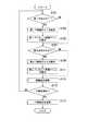
次に、図3及び図9を参照して、タブレット端末装置1の制御部11の動作について説明する。図9は、タブレット端末装置1の制御部11の動作を示すフローチャートである。
図9に示すように、まず、ステップS101において、方向検出部111が第1方向DR1を検出しているか否かを判定する。
方向検出部111が第1方向DR1を検出していないと判定した場合(ステップS101でNO)には、処理がステップS107に進む。方向検出部111が第1方向DR1を検出していると判定した場合(ステップS101でYES)には、処理がステップS103に進む。
そして、ステップS103において、第1設定部112が第1設定画面SC1を表示して、1つの画像の第1印刷条件C1を画像形成装置2に対して設定する。
次に、ステップS105において、プレビューボタンPVBのタッチを受け付けて、第1設定部112が第1印刷条件C1に対応する第1プレビュー画像PV1をディスプレー12Aに表示する。
Next, with reference to FIG.3 and FIG.9, operation | movement of thecontrol part 11 of thetablet terminal device 1 is demonstrated. FIG. 9 is a flowchart showing the operation of thecontrol unit 11 of thetablet terminal device 1.
As shown in FIG. 9, first, in step S101, it is determined whether or not thedirection detection unit 111 detects the first direction DR1.
If thedirection detection unit 111 determines that the first direction DR1 has not been detected (NO in step S101), the process proceeds to step S107. If thedirection detection unit 111 determines that the first direction DR1 is detected (YES in step S101), the process proceeds to step S103.
In step S <b> 103, thefirst setting unit 112 displays the first setting screen SC <b> 1 and sets the first printing condition C <b> 1 of one image for theimage forming apparatus 2.
Next, in step S105, the touch of the preview button PVB is received, and thefirst setting unit 112 displays the first preview image PV1 corresponding to the first printing condition C1 on thedisplay 12A.

そして、ステップS107において、方向検出部111が第2方向DR2を検出しているか否かを判定する。
方向検出部111が第2方向DR2を検出していないと判定した場合(ステップS107でNO)には、処理がステップS113に進む。方向検出部111が第2方向DR2を検出していると判定した場合(ステップS107でYES)には、処理がステップS109に進む。
そして、ステップS109において、第2設定部113が第2設定画面SC2を表示して、1つの画像の第2印刷条件C2を画像形成装置2に対して設定する。
次に、ステップS111において、プレビューボタンPVBのタッチを受け付けて、第2設定部113が第2印刷条件C2に対応する第2プレビュー画像PV2をディスプレー12Aに表示する。
In step S107, it is determined whether or not thedirection detection unit 111 detects the second direction DR2.
If thedirection detection unit 111 determines that the second direction DR2 has not been detected (NO in step S107), the process proceeds to step S113. If it is determined that thedirection detection unit 111 detects the second direction DR2 (YES in step S107), the process proceeds to step S109.
In step S <b> 109, thesecond setting unit 113 displays the second setting screen SC <b> 2 and sets the second printing condition C <b> 2 for one image for theimage forming apparatus 2.
Next, in step S111, the touch of the preview button PVB is received, and thesecond setting unit 113 displays the second preview image PV2 corresponding to the second printing condition C2 on thedisplay 12A.

次いで、ステップS113において、「画像表示処理」が実行される。「画像表示処理」は、方向検出部111が第3方向DP3を検出している場合に、第1設定部112、第2設定部113及び振動検出部114が行う処理である。具体的には、ディスプレー12Aに第1領域R1及び第2領域R2を配置し、第1プレビュー画像PV1及び第2プレビュー画像PV2を表示する。  Next, in step S113, “image display processing” is executed. The “image display process” is a process performed by thefirst setting unit 112, thesecond setting unit 113, and thevibration detection unit 114 when thedirection detection unit 111 detects the third direction DP3. Specifically, the first region R1 and the second region R2 are arranged on thedisplay 12A, and the first preview image PV1 and the second preview image PV2 are displayed.

次に、ステップS115において、実行指示部115が、ユーザーからの1つの入力に基づいて、第1印刷条件C1での印刷及び第2印刷条件C2での印刷の少なくとも一方の実行を画像形成装置2に対して指示するか否かの判定を行う。「1つの入力」は、例えば、ディスプレー12Aに表示された一括実行ボタンのタッチである。一括実行ボタンは、2つのジョブを実行する場合にタッチされる。「2つのジョブ」は、本実施形態では、第1印刷条件C1での印刷ジョブ及び第2印刷条件C2での印刷ジョブを示す。
実行指示部115が印刷の実行を画像形成装置2に対して指示しないと判定した場合(ステップS115でNO)には、処理がステップS101に戻る。実行指示部115が印刷の実行を画像形成装置2に対して指示すると判定した場合(ステップS115でYES)には、処理がステップS117に進む。
そして、ステップS117において、実行指示部115が、印刷の実行を画像形成装置2に対して送信し、処理が終了する。
Next, in step S115, theexecution instructing unit 115 executes at least one of printing under the first printing condition C1 and printing under the second printing condition C2 based on one input from the user. It is determined whether or not an instruction is issued. “One input” is, for example, a touch of a batch execution button displayed on thedisplay 12A. The batch execution button is touched when two jobs are executed. In this embodiment, “two jobs” indicate a print job under the first print condition C1 and a print job under the second print condition C2.
If theexecution instruction unit 115 determines not to instruct theimage forming apparatus 2 to execute printing (NO in step S115), the process returns to step S101. If theexecution instruction unit 115 determines to instruct theimage forming apparatus 2 to execute printing (YES in step S115), the process proceeds to step S117.
In step S117, theexecution instruction unit 115 transmits the execution of printing to theimage forming apparatus 2, and the process ends.

以上、図3及び図9を参照して説明したように、実行指示部115がユーザーからの1つの入力に基づいて、第1印刷条件C1での印刷及び第2印刷条件C2での印刷の実行を画像形成装置2に対して指示する。よって、第1印刷条件C1での印刷及び第2印刷条件C2での印刷を、1つの入力で行うことができる。  As described above with reference to FIGS. 3 and 9, theexecution instruction unit 115 executes printing under the first printing condition C1 and printing under the second printing condition C2 based on one input from the user. To theimage forming apparatus 2. Therefore, printing under the first printing condition C1 and printing under the second printing condition C2 can be performed with one input.

次に、図3及び図10を参照して、タブレット端末装置1の制御部11の「画像表示処理」における動作について説明する。図10は、タブレット端末装置1の制御部11の「画像表示処理」を示すフローチャートである。
図10に示すように、まず、ステップS201において、方向検出部111が第3方向DR3を検出する。
次に、ステップS203において、第1設定部112が角度θ1を求め、第2設定部113が角度θ2を求める。
そして、ステップS205において、第1設定部112が角度θ1に応じて、第1領域R1のサイズを定める。
次に、ステップS207において、第2設定部113が角度θ2に応じて、第2領域R2のサイズを定める。
そして、ステップS209において、第1設定部112が第1領域R1に第1プレビュー画像PV1を表示する。
次に、ステップS211において、第2設定部113が第2領域R2に第2プレビュー画像PV2を表示する。
Next, the operation in the “image display process” of thecontrol unit 11 of thetablet terminal device 1 will be described with reference to FIGS. 3 and 10. FIG. 10 is a flowchart showing the “image display process” of thecontrol unit 11 of thetablet terminal device 1.
As shown in FIG. 10, first, in step S201, thedirection detection unit 111 detects the third direction DR3.
Next, in step S203, thefirst setting unit 112 obtains the angle θ1, and thesecond setting unit 113 obtains the angle θ2.
In step S205, thefirst setting unit 112 determines the size of the first region R1 according to the angle θ1.
Next, in step S207, thesecond setting unit 113 determines the size of the second region R2 according to the angle θ2.
In step S209, thefirst setting unit 112 displays the first preview image PV1 in the first region R1.
Next, in step S211, thesecond setting unit 113 displays the second preview image PV2 in the second region R2.

次いで、ステップS213において、振動検出部114が振動を検出したか否かを判定する。
振動検出部114が振動を検出していない場合(ステップS213でNO)には、処理が図9のステップS115に進む。振動検出部114が振動を検出した場合(ステップS213でYES)には、処理がステップS215に進む。
そして、ステップS215において、振動検出部114が、振動の振幅Aが所定値AS以上であるか否かを判定する。
振動検出部114が、振動の振幅Aが所定値AS以上ではないと判定した場合(ステップS215でNO)には、処理が図9のステップS115に進む。振動検出部114が、振動の振幅Aが所定値AS以上であると判定した場合(ステップS215でYES)には、処理がステップS217に進む。
そして、ステップS217において、第1設定部112及び第2設定部113が、第1領域R1と第2領域R2とのプレビュー画像PV1、PV2を入れ換える。具体的には、第1設定部112が第1領域R1に第2プレビュー画像PV2を表示し、第2設定部113が第2領域R2に第1プレビュー画像PV1を表示する。そして、処理が図9のステップS115に進む。
Next, in step S213, it is determined whether thevibration detection unit 114 has detected vibration.
If thevibration detection unit 114 does not detect vibration (NO in step S213), the process proceeds to step S115 in FIG. If thevibration detection unit 114 detects vibration (YES in step S213), the process proceeds to step S215.
In step S215, thevibration detection unit 114 determines whether the vibration amplitude A is equal to or greater than a predetermined value AS.
If thevibration detection unit 114 determines that the vibration amplitude A is not greater than or equal to the predetermined value AS (NO in step S215), the process proceeds to step S115 in FIG. If thevibration detection unit 114 determines that the vibration amplitude A is greater than or equal to the predetermined value AS (YES in step S215), the process proceeds to step S217.
In step S217, thefirst setting unit 112 and thesecond setting unit 113 exchange the preview images PV1 and PV2 of the first region R1 and the second region R2. Specifically, thefirst setting unit 112 displays the second preview image PV2 in the first region R1, and thesecond setting unit 113 displays the first preview image PV1 in the second region R2. Then, the process proceeds to step S115 in FIG.

以上、図3及び図10を参照して説明したように、振動検出部114が所定値AS以上の振幅Aの振動を検出した場合に、第1設定部112及び第2設定部113は以下の処理を行う。すなわち、第1設定部112が第1領域R1に第2プレビュー画像PV2を表示し、第2設定部113が第2領域R2に第1プレビュー画像PV1を表示する。よって、ユーザーは、タブレット端末装置1を振ることによって、第1領域R1と第2領域R2とに表示するプレビュー画像PV1、PV2を入れ換えることができる。したがって、第1プレビュー画像PV1及び第2プレビュー画像PV2のうち、例えば、詳細な観察を所望するプレビュー画像PV1、PV2を大きく表示することができる。  As described above with reference to FIGS. 3 and 10, when thevibration detection unit 114 detects a vibration having an amplitude A equal to or greater than the predetermined value AS, thefirst setting unit 112 and thesecond setting unit 113 are as follows. Process. That is, thefirst setting unit 112 displays the second preview image PV2 in the first region R1, and thesecond setting unit 113 displays the first preview image PV1 in the second region R2. Therefore, the user can exchange the preview images PV1 and PV2 displayed in the first region R1 and the second region R2 by shaking thetablet terminal device 1. Therefore, among the first preview image PV1 and the second preview image PV2, for example, the preview images PV1 and PV2 for which detailed observation is desired can be displayed large.

以上、図面を参照しながら本発明の実施形態について説明した。ただし、本発明は、上記の実施形態に限られるものではなく、その要旨を逸脱しない範囲で種々の態様において実施することが可能である(例えば、下記に示す(1)〜(5))。図面は、理解し易くするために、それぞれの構成要素を主体に模式的に示しており、図示された各構成要素の厚み、長さ、個数等は、図面作成の都合上から実際とは異なる場合がある。また、上記の実施形態で示す各構成要素の形状、寸法等は一例であって、特に限定されるものではなく、本発明の構成から実質的に逸脱しない範囲で種々の変更が可能である。  The embodiments of the present invention have been described above with reference to the drawings. However, the present invention is not limited to the above-described embodiment, and can be implemented in various modes without departing from the gist thereof (for example, (1) to (5) shown below). For ease of understanding, the drawings schematically show each component as a main component, and the thickness, length, number, etc. of each component shown in the drawings are different from the actual for convenience of drawing. There is a case. Moreover, the shape, dimension, etc. of each component shown by said embodiment are an example, Comprising: It does not specifically limit, A various change is possible in the range which does not deviate substantially from the structure of this invention.

(1)図4〜図8を参照して説明したように、タブレット端末装置1は2つのジョブの実行条件を画像形成装置2に対して設定するが、本発明はこれに限定されない。タブレット端末装置1が3つ以上のジョブの実行条件を画像形成装置2に対して設定する形態でもよい。例えば、タブレット端末装置1が4つのジョブの実行条件を画像形成装置2に対して設定する形態でもよい。具体的には、方向検出部111が第1方向DR1〜第4方向DR4を検出している場合に、それぞれ、第1ジョブJB1〜第4ジョブJB4の実行条件を画像形成装置2に対して設定する。また、第1方向DR1〜第4方向DR4のうち互いに隣接する方向は、90°の角度をなす。例えば、第1方向DR1が、0(零)°である場合には、第2方向DR2〜第4方向DR4は、それぞれ、90°、180°、270°である。この形態では、4つのジョブの実行条件を画像形成装置2に対して設定できる。  (1) As described with reference to FIGS. 4 to 8, thetablet terminal device 1 sets two job execution conditions for theimage forming device 2, but the present invention is not limited to this. Thetablet terminal device 1 may be configured to set execution conditions for three or more jobs for theimage forming apparatus 2. For example, thetablet terminal device 1 may set four job execution conditions for theimage forming device 2. Specifically, when thedirection detection unit 111 detects the first direction DR1 to the fourth direction DR4, the execution conditions of the first job JB1 to the fourth job JB4 are set for theimage forming apparatus 2, respectively. To do. In addition, the adjacent directions among the first direction DR1 to the fourth direction DR4 form an angle of 90 °. For example, when the first direction DR1 is 0 (zero) °, the second direction DR2 to the fourth direction DR4 are 90 °, 180 °, and 270 °, respectively. In this embodiment, four job execution conditions can be set for theimage forming apparatus 2.

(2)図4〜図8を参照して説明したように、第1ジョブJB1及び第2ジョブJB2は印刷ジョブであるが、本発明はこれに限定されない。第1ジョブJB1及び第2ジョブJB2の少なくとも一方が印刷ジョブではない形態でもよい。例えば、第1ジョブJB1が印刷ジョブであって、第2ジョブJB2が画像データ送信ジョブである形態でもよい。画像データ送信ジョブは、例えば、印刷ジョブにおいて生成された原稿Rの画像データを、タブレット端末装置1に送信するジョブである。この形態では、ユーザーが所望する印刷条件で原稿Rの画像データを印刷すると共に、ユーザーが所望する画像条件で原稿Rの画像データをタブレット端末装置1に送信できる。また、図9を参照して説明したように、ユーザーは1つの入力によって、ユーザーが所望する印刷条件で原稿Rの画像データを印刷すると共に、ユーザーが所望する画像条件で原稿Rの画像データをタブレット端末装置1に送信できる。よって、ユーザーは、異なる種類のジョブを1つの入力によって実行することができる。  (2) As described with reference to FIGS. 4 to 8, the first job JB1 and the second job JB2 are print jobs, but the present invention is not limited to this. At least one of the first job JB1 and the second job JB2 may not be a print job. For example, the first job JB1 may be a print job and the second job JB2 may be an image data transmission job. The image data transmission job is a job for transmitting the image data of the document R generated in the print job to thetablet terminal device 1, for example. In this embodiment, the image data of the document R can be printed under the print conditions desired by the user, and the image data of the document R can be transmitted to thetablet terminal device 1 under the image conditions desired by the user. Further, as described with reference to FIG. 9, the user prints the image data of the document R under the printing condition desired by the user by one input, and the image data of the document R under the image condition desired by the user. It can be transmitted to thetablet terminal device 1. Therefore, the user can execute different types of jobs with one input.

(3)図4〜図8を参照して説明したように、方向検出部111が第1方向DR1を検出している場合に、第1設定部112は第1印刷条件C1を画像形成装置2に対して設定するが、本発明はこれに限定されない。また、方向検出部111が第2方向DR2を検出している場合に、第2設定部113は1つの画像の第2印刷条件C2を画像形成装置2に対して設定するが、本発明はこれに限定されない。例えば、ディスプレー12Aの適所に印刷条件設定ボタンを表示し、ユーザーが印刷条件設定ボタンをタッチした場合に、第1印刷条件C1又は第2印刷条件C2を画像形成装置2に対して設定する形態でもよい。この形態では、方向検出部111が第1方向DR1又は第2方向DR2を検出していない場合であっても、第1印刷条件C1及び第2印刷条件C2を画像形成装置2に対して設定することができる。印刷条件設定ボタンは、例えば、第1領域R1及び第2領域R2の内部又は近傍に、それぞれ、表示する形態が好ましい。この形態では、第1領域R1の内部又は近傍に表示された印刷条件設定ボタンをタッチすることによって第1印刷条件C1を設定することができる。また、第2領域R2の内部又は近傍に表示された印刷条件設定ボタンをタッチすることによって第2印刷条件C2を設定することができる。  (3) As described with reference to FIGS. 4 to 8, when thedirection detection unit 111 detects the first direction DR1, thefirst setting unit 112 sets the first printing condition C1 to theimage forming apparatus 2. However, the present invention is not limited to this. In addition, when thedirection detection unit 111 detects the second direction DR2, thesecond setting unit 113 sets the second printing condition C2 for one image for theimage forming apparatus 2. It is not limited to. For example, a printing condition setting button is displayed at an appropriate position on thedisplay 12A, and the first printing condition C1 or the second printing condition C2 is set for theimage forming apparatus 2 when the user touches the printing condition setting button. Good. In this embodiment, even if thedirection detection unit 111 does not detect the first direction DR1 or the second direction DR2, the first printing condition C1 and the second printing condition C2 are set for theimage forming apparatus 2. be able to. For example, the print condition setting button is preferably displayed in or near the first area R1 and the second area R2. In this embodiment, the first printing condition C1 can be set by touching a printing condition setting button displayed in or near the first region R1. Further, the second printing condition C2 can be set by touching a printing condition setting button displayed in or near the second region R2.

(4)図6〜図8を参照して説明したように、第1設定部112は第1領域R1に第1プレビュー画像PV1を表示し、第2設定部113は第2領域R2に第2プレビュー画像PV2を表示するが、本発明はこれに限定されない。ユーザーが、第1領域R1内で所定の操作を行った場合に、第1設定部112が第1プレビュー画像PV1を拡大又は縮小する形態でもよい。また、ユーザーが、第2領域R2内で所定の操作を行った場合に、第2設定部113が第2プレビュー画像PV2を拡大又は縮小する形態でもよい。これらの形態では、第1プレビュー画像PV1及び第2プレビュー画像PV2をユーザーが所望する倍率に拡大又は縮小して表示することができる。所定の操作は、例えば、ピンチアウト操作又はピンチイン操作である。  (4) As described with reference to FIGS. 6 to 8, thefirst setting unit 112 displays the first preview image PV1 in the first region R1, and thesecond setting unit 113 displays the second preview image PV1 in the second region R2. Although the preview image PV2 is displayed, the present invention is not limited to this. When the user performs a predetermined operation in the first region R1, thefirst setting unit 112 may enlarge or reduce the first preview image PV1. Further, when the user performs a predetermined operation in the second region R2, thesecond setting unit 113 may enlarge or reduce the second preview image PV2. In these forms, the first preview image PV1 and the second preview image PV2 can be displayed by being enlarged or reduced to a magnification desired by the user. The predetermined operation is, for example, a pinch-out operation or a pinch-in operation.

具体的には、第1設定部112がピンチアウト操作を検出した場合には、第1設定部112が第1プレビュー画像PV1を拡大表示する。同様に、第2設定部113がピンチアウト操作を検出した場合には、第2設定部113が第2プレビュー画像PV2を拡大表示する。一方、第1設定部112がピンチイン操作を検出した場合には、第1設定部112が第1プレビュー画像PV1を縮小表示する。同様に、第2設定部113がピンチイン操作を検出した場合には、第2設定部113が第2プレビュー画像PV2を縮小表示する。この形態では、第1プレビュー画像PV1及び第2プレビュー画像PV2を、それぞれ、ユーザーが所望する倍率に拡大表示又は縮小表示できる。  Specifically, when thefirst setting unit 112 detects a pinch-out operation, thefirst setting unit 112 enlarges and displays the first preview image PV1. Similarly, when thesecond setting unit 113 detects a pinch-out operation, thesecond setting unit 113 enlarges and displays the second preview image PV2. On the other hand, when thefirst setting unit 112 detects a pinch-in operation, thefirst setting unit 112 displays the first preview image PV1 in a reduced size. Similarly, when thesecond setting unit 113 detects a pinch-in operation, thesecond setting unit 113 displays the second preview image PV2 in a reduced size. In this form, the first preview image PV1 and the second preview image PV2 can be enlarged or reduced at a magnification desired by the user, respectively.

また、第1設定部112又は第2設定部113がピンチアウト操作を検出した場合に、第1設定部112が第1プレビュー画像PV1を拡大表示すると共に、第2設定部113が第2プレビュー画像PV2を拡大表示する形態でもよい。一方、第1設定部112又は第2設定部113がピンチイン操作を検出した場合に、第1設定部112が第1プレビュー画像PV1を縮小表示すると共に、第2設定部113が第2プレビュー画像PV2を縮小表示する。この形態では、第1プレビュー画像PV1及び第2プレビュー画像PV2を、同一の倍率で、拡大表示又は縮小表示できる。  When thefirst setting unit 112 or thesecond setting unit 113 detects a pinch-out operation, thefirst setting unit 112 enlarges and displays the first preview image PV1, and thesecond setting unit 113 displays the second preview image. PV2 may be enlarged and displayed. On the other hand, when thefirst setting unit 112 or thesecond setting unit 113 detects a pinch-in operation, thefirst setting unit 112 displays the first preview image PV1 in a reduced size, and thesecond setting unit 113 displays the second preview image PV2. Is displayed in a reduced size. In this form, the first preview image PV1 and the second preview image PV2 can be enlarged or reduced at the same magnification.

(5)図10を参照して説明したように、振動検出部114が所定値AS以上の振幅Aの振動を検出した場合に第1設定部112及び第2設定部113はプレビュー画像PV1、PV2を入れ換えるが、本発明はこれに限定されない。振動検出部114が振幅及び振動回数が所定の条件を満たすか否かを判定し、所定の条件を満たす場合に第1設定部112及び第2設定部113がプレビュー画像PV1、PV2を入れ換える形態でもよい。「所定の条件」は、例えば、振幅Aが所定値AS以上であって、且つ、振動回数が3回以上である。「振動回数」は、振動の方向が反転する回数の半分を示す。  (5) As described with reference to FIG. 10, when thevibration detection unit 114 detects a vibration having an amplitude A equal to or greater than the predetermined value AS, thefirst setting unit 112 and thesecond setting unit 113 display the preview images PV1 and PV2. However, the present invention is not limited to this. In the form in which thevibration detection unit 114 determines whether the amplitude and the number of vibrations satisfy the predetermined condition, and thefirst setting unit 112 and thesecond setting unit 113 replace the preview images PV1 and PV2 when the predetermined condition is satisfied. Good. The “predetermined condition” is, for example, that the amplitude A is a predetermined value AS or more and the number of vibrations is three or more. “Vibration frequency” indicates half of the number of times the direction of vibration is reversed.

本発明は、情報端末装置、画像形成システム、及びプログラムに利用可能である。  The present invention can be used for an information terminal device, an image forming system, and a program.

100 画像形成システム
1 タブレット端末装置(情報端末装置)
11 制御部
111 方向検出部
112 第1設定部
113 第2設定部
114 振動検出部
115 実行指示部
11A プロセッサー
11B 記憶部
12 タッチパネル
12A ディスプレー
12B タッチセンサー
13 ジャイロセンサー(方向検出部の一部)
14 加速度センサー(振動検出部の一部)
2 画像形成装置
21 画像形成ユニット
22 画像読取ユニット
23 原稿搬送ユニット
24 操作パネル
241 タッチパネル
25 制御部
251 指示受付部
252 ジョブ制御部
25A プロセッサー
25B 記憶部
PV1 第1プレビュー画像
PV2 第2プレビュー画像
100Image forming system 1 Tablet terminal device (information terminal device)
DESCRIPTION OFSYMBOLS 11Control part 111Direction detection part 1121st setting part 1132nd setting part 114Vibration detection part 115Execution instructionpart 11A Processor 11B Memory |storage part 12Touchpanel 12A Display12B Touch sensor 13 Gyro sensor (a part of direction detection part)
14 Accelerometer (part of the vibration detector)
2Image forming apparatus 21Image forming unit 22Image reading unit 23Document transport unit 24Operation panel 241Touch panel 25Control unit 251Instruction receiving unit 252Job controlunit 25A Processor 25B Storage unit PV1 First preview image PV2 Second preview image

Claims (9)

Translated fromJapanese
画像形成装置と通信する情報端末装置であって、
ディスプレーと、
前記ディスプレーの方向を検出する方向検出部と、
前記方向検出部が第1方向を検出している場合に、第1ジョブの設定を前記画像形成装置に対して行う第1設定部と、
前記方向検出部が前記第1方向と反対の方向である第2方向を検出している場合に、前記第1ジョブと相違する第2ジョブの設定を前記画像形成装置に対して行う第2設定部と
を備える、情報端末装置。
An information terminal device that communicates with an image forming apparatus,
Display,
A direction detector for detecting the direction of the display;
A first setting unit configured to set a first job for the image forming apparatus when the direction detection unit detects the first direction;
Second setting for setting the second job setting different from the first job to the image forming apparatus when the direction detecting unit detectsa second direction thatis opposite to the first direction. An information terminal device.
前記第1設定部は、前記ディスプレーに第1設定画面を表示し、前記第1設定画面に対するユーザーからの入力に基づいて前記第1ジョブを前記画像形成装置に対して設定し、
前記第2設定部は、前記ディスプレーに第2設定画面を表示し、前記第2設定画面に対するユーザーからの入力に基づいて前記第2ジョブを前記画像形成装置に対して設定する、請求項1に記載の情報端末装置。
The first setting unit displays a first setting screen on the display, sets the first job for the image forming apparatus based on an input from a user on the first setting screen,
The second setting unit sets a second setting screen displayed on said display, setting the second job to the image forming apparatus based on an input from the user with respect to the second setting screento Claim1 The information terminal device described.
前記第1ジョブ及び前記第2ジョブは、画像の印刷ジョブであって、
前記第1設定部は、前記画像の第1印刷条件を前記画像形成装置に対して設定すると共に、前記第1印刷条件に対応する第1プレビュー画像を前記ディスプレーに表示し、
前記第2設定部は、前記画像の第2印刷条件を前記画像形成装置に対して設定すると共に、前記第2印刷条件に対応する第2プレビュー画像を前記ディスプレーに表示する、請求項1又は請求項2に記載の情報端末装置。
The first job and the second job are image print jobs,
The first setting unit sets a first printing condition of the image for the image forming apparatus and displays a first preview image corresponding to the first printing condition on the display.
The second setting unit sets a second printing condition of the image on the image forming apparatus to display a second preview image corresponding to the second printing conditions on the display, according to claim 1or claim Item 3. The information terminal device accordingto Item 2 .
前記方向検出部が前記第1方向と前記第2方向との間の第3方向を検出している場合に、前記第1設定部は、前記ディスプレーの第1領域に前記第1プレビュー画像を表示し、前記第2設定部は、前記ディスプレーの前記第1領域とは相違する第2領域に前記第2プレビュー画像を表示する、請求項に記載の情報端末装置。When the direction detection unit detects a third direction between the first direction and the second direction, the first setting unit displays the first preview image in the first region of the display. The information terminal device according to claim3 , wherein the second setting unit displays the second preview image in a second area different from the first area of the display. 前記方向検出部が前記第3方向を検出している場合に、
前記第1設定部は、前記第1方向と前記第3方向とのなす角度に応じて、前記第1領域のサイズを定め、
前記第2設定部は、前記第2方向と前記第3方向とのなす角度に応じて、前記第2領域のサイズを定める、請求項に記載の情報端末装置。
When the direction detection unit detects the third direction,
The first setting unit determines a size of the first region according to an angle formed by the first direction and the third direction,
5. The information terminal device according to claim4 , wherein the second setting unit determines a size of the second region according to an angle formed by the second direction and the third direction.
前記第1設定部は、前記第1方向と前記第3方向とのなす角度の大きさに基づいて、前記第1領域のサイズを変更し、
前記第2設定部は、前記第2方向と前記第3方向とのなす角度の大きさに基づいて、前記第2領域のサイズを変更する、請求項に記載の情報端末装置。
The first setting unit changes a size of the first region based on an angle between the first direction and the third direction,
The information terminal device according to claim5 , wherein the second setting unit changes the size of the second region based on an angle between the second direction and the third direction.
ユーザーからの1つの入力に基づいて、前記第1ジョブ及び前記第2ジョブの実行を前記画像形成装置に対して指示する実行指示部を更に備える、請求項1から請求項のいずれか1項に記載の情報端末装置。Based on one input from a user, further comprising an execution instruction unit for instructing the execution of the first job and the second job to the image forming apparatus, any one of claims 1 to6 The information terminal device described in 1. ディスプレーを備えた情報端末装置と、前記情報端末装置と通信する画像形成装置とを備える画像形成システムであって、
前記情報端末装置は、
前記ディスプレーの方向を検出する方向検出部と、
前記方向検出部が第1方向を検出している場合に、第1ジョブの設定を前記画像形成装置に対して行う第1設定部と、
前記方向検出部が前記第1方向と反対の方向である第2方向を検出している場合に、前記第1ジョブと相違する第2ジョブの設定を前記画像形成装置に対して行う第2設定部と
を備え、
前記画像形成装置は、
前記情報端末装置からの指示を受け付ける指示受付部と、
前記指示受付部が受け付けた指示に従って前記第1ジョブ及び前記第2ジョブの設定を行うジョブ制御部と
を備える、画像形成システム。
An image forming system comprising an information terminal device provided with a display and an image forming device communicating with the information terminal device,
The information terminal device
A direction detector for detecting the direction of the display;
A first setting unit configured to set a first job for the image forming apparatus when the direction detection unit detects the first direction;
Second setting for setting the second job setting different from the first job to the image forming apparatus when the direction detecting unit detectsa second direction thatis opposite to the first direction. With
The image forming apparatus includes:
An instruction receiving unit for receiving an instruction from the information terminal device;
An image forming system comprising: a job control unit configured to set the first job and the second job in accordance with an instruction received by the instruction receiving unit.
情報端末装置に記憶されるプログラムであって、
前記情報端末装置は、ディスプレーとコンピューターとを備え、画像形成装置と通信し、
前記コンピューターを、
前記ディスプレーの方向を検出する方向検出部と、
前記方向検出部が第1方向を検出している場合に、第1ジョブの設定を前記画像形成装置に対して行う第1設定部と、
前記方向検出部が前記第1方向と反対の方向である第2方向を検出している場合に、前記第1ジョブと相違する第2ジョブの設定を前記画像形成装置に対して行う第2設定部と
して機能させる、プログラム。

A program stored in an information terminal device,
The information terminal device includes a display and a computer, and communicates with an image forming device.
The computer,
A direction detector for detecting the direction of the display;
A first setting unit configured to set a first job for the image forming apparatus when the direction detection unit detects the first direction;
Second setting for setting the second job setting different from the first job to the image forming apparatus when the direction detecting unit detectsa second direction thatis opposite to the first direction. A program that functions as a part.

JP2016043265A2016-03-072016-03-07 Information terminal device, image forming system, and programExpired - Fee RelatedJP6443363B2 (en)

Priority Applications (1)

Application NumberPriority DateFiling DateTitle
JP2016043265AJP6443363B2 (en)2016-03-072016-03-07 Information terminal device, image forming system, and program

Applications Claiming Priority (1)

Application NumberPriority DateFiling DateTitle
JP2016043265AJP6443363B2 (en)2016-03-072016-03-07 Information terminal device, image forming system, and program

Publications (2)

Publication NumberPublication Date
JP2017161980A JP2017161980A (en)2017-09-14
JP6443363B2true JP6443363B2 (en)2018-12-26

Family

ID=59858009

Family Applications (1)

Application NumberTitlePriority DateFiling Date
JP2016043265AExpired - Fee RelatedJP6443363B2 (en)2016-03-072016-03-07 Information terminal device, image forming system, and program

Country Status (1)

CountryLink
JP (1)JP6443363B2 (en)

Family Cites Families (5)

* Cited by examiner, † Cited by third party
Publication numberPriority datePublication dateAssigneeTitle
JP2001312385A (en)*2000-04-282001-11-09Canon Inc Print control apparatus and method, and storage medium
JP5836708B2 (en)*2011-09-022015-12-24キヤノン株式会社 Terminal device, information processing method, and program
JP5652433B2 (en)*2012-06-112015-01-14コニカミノルタ株式会社 PRINT SETTING DEVICE, PRINT SETTING DEVICE CONTROL METHOD, PRINT SETTING DEVICE CONTROL PROGRAM, AND PRINTING DEVICE
JP6180980B2 (en)*2014-03-262017-08-16京セラドキュメントソリューションズ株式会社 Image forming system and portable terminal
JP6095614B2 (en)*2014-07-182017-03-15ヤフー株式会社 Information display program, distribution device, information display method, and information display device

Also Published As

Publication numberPublication date
JP2017161980A (en)2017-09-14

Similar Documents

PublicationPublication DateTitle
US9516182B2 (en)Image forming apparatus that enhances operability on screen displayed as split screens
US20160191730A1 (en)Image processing apparatus
US20140376043A1 (en)Job processing apparatus, display control method of job processing apparatus, and storage medium
JP6351431B2 (en) Control device, control method, and program
US9749488B2 (en)Image reading apparatus that reads by intended read size and image processing apparatus
JP6142564B2 (en) Information display device and display control program
JP6443363B2 (en) Information terminal device, image forming system, and program
JP6269537B2 (en) Display input device, image forming apparatus including the same, display input device control method, and program
CN103686041A (en) Display input device and electronic equipment provided with the display input device
JP2016218841A (en) Display device and image forming apparatus
JP5298812B2 (en) Image forming apparatus
JP6178741B2 (en) Electronics
CN111688369A (en)Electronic device and storage medium
JP6089583B2 (en) Portable input reception device and input reception program
JP6274134B2 (en) Display input device and image forming apparatus having the same
JP5659193B2 (en) Display input device and image forming apparatus
JP2016045544A (en) Input / display device and image forming apparatus
JP2017207794A (en) Operation input device, image forming apparatus, and operation input method
JP2015142272A (en)Image processing device, image forming apparatus, portable terminal device, and image processing system
JP6319201B2 (en) Display device and image forming apparatus
JP7545638B2 (en) Printing device, print production method and program
JP5866040B2 (en) Display input device and image forming apparatus
US20250310448A1 (en)Information processing system, non-transitory computer readable medium, and information processing method
JP2023042911A (en)Input device, input method, and image formation device
JP6350470B2 (en) Display device and image forming apparatus

Legal Events

DateCodeTitleDescription
A621Written request for application examination

Free format text:JAPANESE INTERMEDIATE CODE: A621

Effective date:20171227

A977Report on retrieval

Free format text:JAPANESE INTERMEDIATE CODE: A971007

Effective date:20180724

A131Notification of reasons for refusal

Free format text:JAPANESE INTERMEDIATE CODE: A131

Effective date:20180807

A521Request for written amendment filed

Free format text:JAPANESE INTERMEDIATE CODE: A523

Effective date:20180921

TRDDDecision of grant or rejection written
A01Written decision to grant a patent or to grant a registration (utility model)

Free format text:JAPANESE INTERMEDIATE CODE: A01

Effective date:20181030

A61First payment of annual fees (during grant procedure)

Free format text:JAPANESE INTERMEDIATE CODE: A61

Effective date:20181112

R150Certificate of patent or registration of utility model

Ref document number:6443363

Country of ref document:JP

Free format text:JAPANESE INTERMEDIATE CODE: R150

LAPSCancellation because of no payment of annual fees

[8]ページ先頭

©2009-2025 Movatter.jp