JP6442154B2 - Image acquisition apparatus and image acquisition method - Google Patents
Image acquisition apparatus and image acquisition methodDownload PDFInfo
- Publication number
- JP6442154B2 JP6442154B2JP2014089350AJP2014089350AJP6442154B2JP 6442154 B2JP6442154 B2JP 6442154B2JP 2014089350 AJP2014089350 AJP 2014089350AJP 2014089350 AJP2014089350 AJP 2014089350AJP 6442154 B2JP6442154 B2JP 6442154B2
- Authority
- JP
- Japan
- Prior art keywords
- image
- amplification factor
- image acquisition
- pixels
- imaging condition
- Prior art date
- Legal status (The legal status is an assumption and is not a legal conclusion. Google has not performed a legal analysis and makes no representation as to the accuracy of the status listed.)
- Active
Links
- 238000000034methodMethods0.000titleclaimsdescription16
- 230000003321amplificationEffects0.000claimsdescription119
- 238000003199nucleic acid amplification methodMethods0.000claimsdescription119
- 238000003384imaging methodMethods0.000claimsdescription79
- 230000005855radiationEffects0.000claimsdescription42
- 238000001514detection methodMethods0.000claimsdescription39
- 238000006243chemical reactionMethods0.000claimsdescription24
- 230000005540biological transmissionEffects0.000description48
- 238000012935AveragingMethods0.000description4
- 238000007689inspectionMethods0.000description4
- 229910052684CeriumInorganic materials0.000description2
- 238000010586diagramMethods0.000description2
- 230000009977dual effectEffects0.000description2
- 230000002123temporal effectEffects0.000description2
- 229910052688GadoliniumInorganic materials0.000description1
- 229910052771TerbiumInorganic materials0.000description1
- 230000000295complement effectEffects0.000description1
- 239000006185dispersionSubstances0.000description1
- 230000000694effectsEffects0.000description1
- 235000013305foodNutrition0.000description1
- 229910052500inorganic mineralInorganic materials0.000description1
- 230000010354integrationEffects0.000description1
- 239000000463materialSubstances0.000description1
- 235000013372meatNutrition0.000description1
- 239000002184metalSubstances0.000description1
- 229910052751metalInorganic materials0.000description1
- 229910044991metal oxideInorganic materials0.000description1
- 150000004706metal oxidesChemical class0.000description1
- 239000011707mineralSubstances0.000description1
- 239000011347resinSubstances0.000description1
- 229920005989resinPolymers0.000description1
- 239000004065semiconductorSubstances0.000description1
- 239000002699waste materialSubstances0.000description1
Images


Classifications
- G—PHYSICS
- G01—MEASURING; TESTING
- G01N—INVESTIGATING OR ANALYSING MATERIALS BY DETERMINING THEIR CHEMICAL OR PHYSICAL PROPERTIES
- G01N23/00—Investigating or analysing materials by the use of wave or particle radiation, e.g. X-rays or neutrons, not covered by groups G01N3/00 – G01N17/00, G01N21/00 or G01N22/00
- G01N23/02—Investigating or analysing materials by the use of wave or particle radiation, e.g. X-rays or neutrons, not covered by groups G01N3/00 – G01N17/00, G01N21/00 or G01N22/00 by transmitting the radiation through the material
- G01N23/04—Investigating or analysing materials by the use of wave or particle radiation, e.g. X-rays or neutrons, not covered by groups G01N3/00 – G01N17/00, G01N21/00 or G01N22/00 by transmitting the radiation through the material and forming images of the material
- G—PHYSICS
- G01—MEASURING; TESTING
- G01T—MEASUREMENT OF NUCLEAR OR X-RADIATION
- G01T1/00—Measuring X-radiation, gamma radiation, corpuscular radiation, or cosmic radiation
- G01T1/16—Measuring radiation intensity
- G01T1/20—Measuring radiation intensity with scintillation detectors
- G01T1/2018—Scintillation-photodiode combinations
- G01T1/20184—Detector read-out circuitry, e.g. for clearing of traps, compensating for traps or compensating for direct hits
- G—PHYSICS
- G01—MEASURING; TESTING
- G01T—MEASUREMENT OF NUCLEAR OR X-RADIATION
- G01T1/00—Measuring X-radiation, gamma radiation, corpuscular radiation, or cosmic radiation
- G01T1/16—Measuring radiation intensity
- G01T1/20—Measuring radiation intensity with scintillation detectors
- G01T1/208—Circuits specially adapted for scintillation detectors, e.g. for the photo-multiplier section
Landscapes
- Physics & Mathematics (AREA)
- Health & Medical Sciences (AREA)
- Life Sciences & Earth Sciences (AREA)
- General Physics & Mathematics (AREA)
- High Energy & Nuclear Physics (AREA)
- Molecular Biology (AREA)
- Spectroscopy & Molecular Physics (AREA)
- Chemical & Material Sciences (AREA)
- Analytical Chemistry (AREA)
- Biochemistry (AREA)
- General Health & Medical Sciences (AREA)
- Immunology (AREA)
- Pathology (AREA)
- Analysing Materials By The Use Of Radiation (AREA)
- Measurement Of Radiation (AREA)
- Endoscopes (AREA)
- Instruments For Viewing The Inside Of Hollow Bodies (AREA)
- Apparatus For Radiation Diagnosis (AREA)
Description
Translated fromJapanese本発明は、対象物の放射線画像を取得する画像取得装置及び画像取得方法に関する。 The present invention relates to an image acquisition apparatus and an image acquisition method for acquiring a radiographic image of an object.
異物検査等を目的として、ベルトコンベア上を流れる対象物の放射線画像(放射線透過画像)を取得する画像取得装置が知られている(例えば特許文献1参照)。このような画像取得装置では、ラインスキャンカメラを用いて、搬送される対象物の放射線画像を取得している。 An image acquisition device that acquires a radiographic image (radiation transmission image) of an object flowing on a belt conveyor is known for the purpose of foreign object inspection or the like (see, for example, Patent Document 1). In such an image acquisition device, a radiation image of the object to be conveyed is acquired using a line scan camera.
上述した放射線画像を用いた技術は、異物検査等を行う上で極めて有効な技術であるが、取得される放射線画像のより一層の鮮明度向上が求められている。そこで本発明は、より鮮明な放射線画像を取得することができる画像取得装置及び画像取得方法を提供することを目的とする。 The above-described technique using a radiographic image is an extremely effective technique for performing foreign object inspection or the like, but further improvement in the sharpness of the acquired radiographic image is required. Then, an object of this invention is to provide the image acquisition apparatus and image acquisition method which can acquire a clearer radiographic image.
本発明に係る画像取得装置は、搬送方向に搬送される対象物の放射線画像を取得する画像取得装置であって、放射線を出力する放射線源と、対象物を搬送方向に搬送する搬送手段と、対象物を透過した放射線をシンチレーション光に変換する変換部、シンチレーション光を検出し検出信号を出力するラインスキャンカメラ部、及び、所定の設定増幅率にて検出信号を増幅し該増幅信号を出力する増幅部を有する検出手段と、増幅信号に基づいて、放射線画像を生成する画像生成部と、所定の撮像条件に基づいて、第1の増幅率又は第1の増幅率よりも低い増幅率である第2の増幅率のいずれか一方を設定増幅率として設定する設定手段と、を備える。 An image acquisition apparatus according to the present invention is an image acquisition apparatus that acquires a radiation image of an object conveyed in a conveyance direction, a radiation source that outputs radiation, a conveyance unit that conveys the object in the conveyance direction, A conversion unit that converts radiation transmitted through the object into scintillation light, a line scan camera unit that detects scintillation light and outputs a detection signal, and amplifies the detection signal at a predetermined set amplification factor and outputs the amplified signal The detection means having an amplification unit, an image generation unit that generates a radiographic image based on the amplification signal, and a first amplification factor or an amplification factor lower than the first amplification factor based on a predetermined imaging condition Setting means for setting any one of the second amplification factors as a set amplification factor.
また、本発明に係る画像取得装置は、搬送方向に搬送される対象物の放射線画像を取得する装置であって、放射線を出力する放射線源と、対象物を搬送方向に搬送する搬送手段と、対象物を透過した放射線をシンチレーション光に変換する変換部、シンチレーション光を検出し検出信号を出力するラインスキャンカメラ部、及び、所定の撮像条件に基づいて設定された増幅率にて検出信号を増幅し該増幅信号を出力する増幅部を有する検出手段と、増幅信号に基づいて、放射線画像を生成する画像生成部と、を備える。 Further, an image acquisition apparatus according to the present invention is an apparatus that acquires a radiographic image of an object conveyed in the conveyance direction, a radiation source that outputs radiation, a conveyance unit that conveys the object in the conveyance direction, A conversion unit that converts radiation transmitted through the object into scintillation light, a line scan camera unit that detects scintillation light and outputs a detection signal, and amplifies the detection signal at an amplification factor set based on predetermined imaging conditions And a detecting unit having an amplifying unit for outputting the amplified signal, and an image generating unit for generating a radiation image based on the amplified signal.
これらの画像取得装置では、対象物を透過した放射線に基づく検出信号が所定の設定増幅率にて増幅されて放射線画像が生成される。そして、設定増幅率は、所定の撮像条件に基づいて設定され、例えば、第1の増幅率又は第1の増幅率よりも低い増幅率である第2の増幅率のいずれか一方が設定される。鮮明な放射線画像を生成するために適切な増幅率は撮像条件によって変わるものであるところ、撮像条件に応じて設定増幅率が設定(選択)されることにより、鮮明な放射線画像を生成することができる。 In these image acquisition devices, a detection signal based on radiation transmitted through an object is amplified at a predetermined set amplification factor to generate a radiation image. The set amplification factor is set based on a predetermined imaging condition. For example, either the first amplification factor or the second amplification factor that is lower than the first amplification factor is set. . An appropriate amplification factor for generating a clear radiographic image varies depending on the imaging conditions. However, a set radiographic image is set (selected) in accordance with the imaging conditions to generate a clear radiographic image. it can.
また、ラインスキャンカメラ部は、搬送方向と交差する方向に並列した複数のラインセンサを有してもよい。これにより、搬送方向に搬送される対象物に係るシンチレーション光を、搬送方向と交差する方向に並列した複数のラインセンサで確実に検出することができる。 Further, the line scan camera unit may include a plurality of line sensors arranged in parallel in a direction intersecting the transport direction. Thereby, the scintillation light which concerns on the target object conveyed in a conveyance direction can be reliably detected with the several line sensor paralleled in the direction which cross | intersects a conveyance direction.
また、撮像条件は、放射線画像の複数の画素の輝度値に関するパラメータであってもよい。画素の輝度値を撮像条件とすることにより、設定増幅率を適切に設定することができる。 Further, the imaging condition may be a parameter related to luminance values of a plurality of pixels of the radiation image. By setting the luminance value of the pixel as an imaging condition, the set amplification factor can be set appropriately.
また、撮像条件は、画像生成部により生成される放射線画像に基づいて設定されたものであってもよい。画像生成部により生成される放射線画像に基づいて撮像条件を設定することにより、撮像条件を確実且つ容易に設定することができる。 Further, the imaging condition may be set based on a radiation image generated by the image generation unit. By setting the imaging condition based on the radiation image generated by the image generation unit, the imaging condition can be set reliably and easily.
また、撮像条件は、設定増幅率を第1の増幅率とした環境下で、画像生成部により生成される放射線画像に基づいて設定されたものであってもよい。比較的増幅率が高い第1の増幅率で生成された放射線画像は、画素の輝度値に関するパラメータの特定が容易である。そのため、当該放射線画像に基づいて、撮像条件を適切に設定することができる。 Further, the imaging condition may be set based on a radiation image generated by the image generation unit in an environment where the set amplification factor is the first amplification factor. The radiation image generated with the first amplification factor having a relatively high amplification factor makes it easy to specify parameters relating to the luminance value of the pixel. Therefore, it is possible to appropriately set the imaging condition based on the radiation image.
また、輝度値に関するパラメータは、放射線画像の複数の画素の輝度値の統計値であってもよい。これにより、設定増幅率をより適切に設定することができる。 Further, the parameter relating to the luminance value may be a statistical value of luminance values of a plurality of pixels of the radiation image. Thereby, the set amplification factor can be set more appropriately.
また、統計値は、複数の画素の輝度値のばらつき度合いであってもよい。ばらつき度合いを考慮することにより、設定増幅率を適切に設定することができる。 Further, the statistical value may be a degree of variation in luminance values of a plurality of pixels. By considering the degree of variation, the set amplification factor can be set appropriately.
また、放射線画像の複数の画素は、放射線画像の異なる空間に係る複数の画素であってもよい。これにより、放射線画像の異なる空間に係る複数の画素のパラメータを考慮して、設定増幅率を適切に設定することができる。 Further, the plurality of pixels of the radiographic image may be a plurality of pixels in different spaces of the radiographic image. Thereby, the set amplification factor can be appropriately set in consideration of parameters of a plurality of pixels related to different spaces of the radiographic image.
また、放射線画像の複数の画素は、放射線画像の異なる時間に係る複数の画素であってもよい。これにより、放射線画像の異なる時間に係る複数の画素のパラメータを考慮して、設定増幅率を適切に設定することができる。 Further, the plurality of pixels of the radiographic image may be a plurality of pixels related to different times of the radiographic image. Thereby, the set amplification factor can be appropriately set in consideration of parameters of a plurality of pixels related to different times of the radiographic image.
また、撮像条件は、放射線源の出力パラメータであってもよい。放射線源出力パラメータを撮像条件とすることにより、設定増幅率を適切に設定することができる。 Further, the imaging condition may be an output parameter of the radiation source. By setting the radiation source output parameter as an imaging condition, the set amplification factor can be set appropriately.
また、設定手段は、撮像条件のパラメータに対応するテーブルを有し、該テーブルを用いて設定増幅率を設定してもよい。テーブルを用いて設定増幅率を設定することにより、設定増幅率の設定を確実且つ簡易に行うことができる。 Further, the setting means may have a table corresponding to the imaging condition parameter, and set the set amplification factor using the table. By setting the set gain using the table, the set gain can be set reliably and easily.
また、設定手段は、撮像条件のパラメータに対応する閾値を有し、該閾値を用いて設定増幅率を設定してもよい。閾値を用いて設定増幅率を設定することにより、設定増幅率の設定を確実且つ簡易に行うことができる。 The setting unit may have a threshold value corresponding to the parameter of the imaging condition, and set the set amplification factor using the threshold value. By setting the set gain using the threshold value, the set gain can be set reliably and easily.
本発明に係る画像取得方法は、対象物を透過した放射線をシンチレーション光に変換し、ラインスキャンカメラ部によりシンチレーション光を検出し検出信号を出力するステップと、所定の撮像条件に基づいて、第1の増幅率又は第1の増幅率よりも低い増幅率である第2の増幅率のいずれか一方を設定増幅率として設定するステップと、設定増幅率にて検出信号を増幅し増幅信号を出力するステップと、増幅信号に基づいて放射線画像を生成するステップと、を備える。 According to the image acquisition method of the present invention, the radiation transmitted through the object is converted into scintillation light, the scintillation light is detected by the line scan camera unit, and the detection signal is output. A step of setting one of the second amplification factor and the second amplification factor that is lower than the first amplification factor as a set amplification factor, and amplifying the detection signal at the set amplification factor and outputting the amplified signal And a step of generating a radiation image based on the amplified signal.
また、本発明に係る画像取得方法は、対象物を搬送方向に搬送しながら、ラインスキャンカメラ部により対象物を透過した放射線を検出し、検出信号を出力し、所定の撮像条件に基づいた増幅率で検出信号を増幅して増幅信号を出力し、増幅信号に基づいて放射線画像を生成する、各ステップを備える。 In addition, the image acquisition method according to the present invention detects the radiation transmitted through the object by the line scan camera unit while conveying the object in the conveying direction, outputs a detection signal, and amplifies based on a predetermined imaging condition. Each step includes amplifying the detection signal at a rate, outputting an amplified signal, and generating a radiation image based on the amplified signal.
本発明によれば、鮮明な放射線画像を取得することができる。 According to the present invention, a clear radiation image can be acquired.
以下、図面を参照しつつ本実施形態に係る画像取得装置、及び、画像取得装置を用いた画像取得方法について説明する。なお、図面の説明においては同一又は相当部分には同一符号を付し、重複する説明を省略する。 Hereinafter, an image acquisition apparatus according to the present embodiment and an image acquisition method using the image acquisition apparatus will be described with reference to the drawings. In the description of the drawings, the same or corresponding parts are denoted by the same reference numerals, and redundant description is omitted.
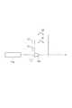
図1は、本実施形態に係る画像取得装置1の構成図である。図1に示されるように、画像取得装置1は、搬送方向TDに搬送される対象物Fに対してX線(放射線)を照射し、対象物Fを透過したX線に基づきX線透過画像(放射線画像)を取得する、X線透過画像取得装置である。画像取得装置1は、X線透過画像を用いて対象物Fに含まれる異物検出又は手荷物検査、基板検査等を行う。画像取得装置1は、ベルトコンベア(搬送手段)60と、X線照射器(放射線源)50と、X線検出カメラ(検出手段、設定手段)10と、制御装置(画像生成部)20と、表示装置30と、各種入力を行うための入力装置40と、を備えて構成されている。 FIG. 1 is a configuration diagram of an
ベルトコンベア60は、対象物Fが載置されるベルト部を有しており、該ベルト部を搬送方向TDに移動させることにより、対象物Fを所定の搬送速度で搬送方向TDに搬送する。対象物Fの搬送速度は、例えば48m/分である。ベルトコンベア60は、必要に応じて、搬送速度を、例えば24m/分や、96m/分等の搬送速度に変更することができる。また、ベルトコンベア60は、ベルト部の高さ位置を適宜変更し、X線照射器50と対象物Fとの距離を変更することができる。なお、ベルトコンベア60で搬送される対象物Fとしては、例えば、食肉等の食品、タイヤ等のゴム製品、樹脂製品、金属製品、鉱物等の資源材料、廃棄物、及び電子部品や電子基板等、様々な物品を挙げることができる。 The
X線照射器50は、X線源としてX線を対象物Fに照射(出力)する装置である。X線照射器50は、点光源であり、一定の照射方向に所定の角度範囲でX線を拡散させて照射する。X線照射器50は、X線の照射方向がベルトコンベア60に向けられると共に、拡散するX線が対象物Fの幅方向(搬送方向TDと交差する方向)全体に及ぶように、ベルトコンベア60から所定の距離を離れてベルトコンベア60の上方に配置されている。また、X線照射器50は、対象物Fの長さ方向(搬送方向TDと平行な方向)においては、長さ方向における所定の分割範囲が照射範囲とされ、対象物Fがベルトコンベア60にて搬送方向TDへ搬送されることにより、対象物Fの長さ方向全体に対してX線が照射されるようになっている。X線照射器50は、制御装置20により管電圧及び管電流が設定され、設定された管電圧及び管電流に応じた所定のエネルギー、放射線量のX線を、ベルトコンベア60に向けて照射する。 The
X線検出カメラ10は、X線照射器50により対象物Fに照射されたX線のうち、対象物Fを透過したX線を検出し、該X線に基づく信号を出力する。X線検出カメラ10は、X線を検出する構成が2組配置されたデュアルラインX線カメラである。本実施形態に係る画像取得装置1では、デュアルラインX線カメラのそれぞれのライン(第1のライン及び第2のライン)で検出されたX線に基づき、それぞれX線透過画像が生成される。そして、生成された2つのX線透過画像について、平均処理又は加算処理等を行うことによって、1つのラインで検出されたX線に基づきX線透過画像を生成する場合と比べて、少ないX線量で鮮明な(輝度の大きい)画像を取得することができる。 The
X線検出カメラ10は、シンチレータ(変換部)11a,11bと、ラインスキャンカメラ(ラインスキャンカメラ部)12a,12bと、センサ制御部13と、アンプ(増幅部)14a,14bと、AD変換器15a,15bと、補正回路16a,16bと、出力インターフェース17a,17bと、アンプ制御部(設定手段)18と、を有している。シンチレータ11a、ラインスキャンカメラ12a、アンプ14a、AD変換器15a、補正回路16a、及び出力インターフェース17aはそれぞれ電気的に接続されており、第1のラインに係る構成である。また、シンチレータ11b、ラインスキャンカメラ12b、アンプ14b、AD変換器15b、補正回路16b、及び出力インターフェース17bはそれぞれ電気的に接続されており、第2のラインに係る構成である。第1のラインのラインスキャンカメラ12aと、第2のラインのラインスキャンカメラ12bとは、搬送方向TDに沿って並んで配置されている。なお、以下では、第1のラインと第2のラインとで共通する構成については、第1のラインの構成を代表して説明する。 The
シンチレータ11aは、ラインスキャンカメラ12a上に接着等により固定されており、対象物Fを透過したX線をシンチレーション光に変換する。シンチレータ11aは、シンチレーション光をラインスキャンカメラ12aに出力する。 The
ラインスキャンカメラ12aは、シンチレータ11aからのシンチレーション光を検出し、電荷に変換して、検出信号(電気信号)としてアンプ14aに出力する。ラインスキャンカメラ12aは、搬送方向TDと交差する方向に並列した複数のラインセンサを有している。ラインセンサは、例えばCCD(Charge Coupled Device)イメージセンサやCMOS(ComplementaryMetal-Oxide Semiconductor)イメージセンサ等であり、複数のフォトダイオードを含んでいる。 The
センサ制御部13は、ラインスキャンカメラ12a,12bが、対象物Fの同じ領域を透過したX線を撮像できるように、ラインスキャンカメラ12a,12bを、所定の検出周期で繰り返し撮像するよう制御する。所定の検出周期は、例えば、ラインスキャンカメラ12a,12b間の距離、ベルトコンベア60の速度、X線照射器50とベルトコンベア60上の対象物Fとの距離(FOD(Focus Object Distance:線源物体間距離))、並びに、X線照射器50とラインスキャンカメラ12a,12bとの距離(FDD(FocusDetector Distance:線源センサ間距離))に基づいて、ラインスキャンカメラ12a,12b共通の周期が設定されてもよい。また、所定の周期は、ラインスキャンカメラ12a,12bそれぞれのラインセンサの画素配列方向と直交する方向のフォトダイオードの画素幅に基づいて、それぞれ個別に設定されてもよい。この場合には、ラインスキャンカメラ12a,12b間の距離、ベルトコンベア60の速度、X線照射器50とベルトコンベア60上の対象物Fとの距離(FOD(Focus Object Distance:線源物体間距離))、並びに、X線照射器50とラインスキャンカメラ12a,12bとの距離(FDD(FocusDetector Distance:線源センサ間距離))に応じて、ラインスキャンカメラ12a,12b間の検出周期のズレ(遅延時間)を特定し、それぞれ個別の周期が設定されてもよい。 The
アンプ14aは、所定の設定増幅率にて検出信号を増幅し、該増幅信号をAD変換器15aに出力する。設定増幅率は、アンプ制御部18によって設定される増幅率である。アンプ制御部18は、所定の撮像条件(制御装置20における選択。詳細は後述)に基づいて、アンプ14a,14bの設定増幅率を、比較的高い増幅率である高ゲイン(第1の増幅率)、又は、高ゲインよりも低い増幅率である低ゲイン(第2の増幅率)のいずれか一方に設定する。ゲイン変換は電気容量の切り替えにより行い、例えば0.5pFから15pFまでを0.5pF刻みで30種類選択することが可能となっている。低ゲインは高ゲインよりも相対的に低い増幅率であればよく、例えば、最大値の15pFを1倍とすると、低ゲインは、1倍の増幅率であり、高ゲインは、2倍の増幅率である。なお、電気容量は自由に組み合わせることができ、電気容量の数は何種類であってもよく、低ゲインと高ゲインの範囲は自由に設定してもよい。 The
アンプ14aは、例えば、図2及び図3に示すように、電流信号を増幅する電流電圧変換アンプ14x、及び、電圧信号を増幅する電圧増幅アンプ14yの少なくもいずれか一方を用いることができる。アンプ14aが電流電圧変換アンプ14xにより構成される場合、並びに、アンプ14aが電流電圧変換アンプ14x及び電圧増幅アンプ14yにより構成される場合のそれぞれについて、アンプ制御部18による設定増幅率の設定を、図2及び図3も参照して詳細に説明する。図2に示す例は電流電圧変換アンプ14xに電気容量が並列接続されている例であり、図3に示す例は電圧増幅アンプ14yに帰還抵抗が並列接続されている例である。 For example, as shown in FIGS. 2 and 3, the
図2に示す例では、電流電圧変換アンプ14xは、ラインスキャンカメラ12aのフォトダイオードから出力された電流信号(検出信号)を電圧信号に変換する。電流電圧変換アンプ14xには、電気容量C1が並列接続されている。これにより、電流信号は電気容量C1に応じた増幅率(例えば上述した第2の増幅率)にて増幅され、電圧信号として出力される。また、電流電圧変換アンプ14xには、電気容量C2がスイッチS1を介して並列接続されている。当該スイッチS1が接続状態(閉状態)とされることにより、電流信号は、電気容量C1及び電気容量C2トータルの電気容量に応じた、電気容量C1のみの場合の増幅率よりも大きい増幅率(例えば上述した第1の増幅率)にて増幅され、電圧信号として出力される。また、電流電圧変換アンプ14xには、スイッチS2が並列接続されている。当該スイッチS2は、電気容量をリセットするためのスイッチである。アンプ制御部18は、スイッチS1及びスイッチS2の開閉を制御することにより、電流電圧変換アンプ14xの設定増幅率を設定する。なお、電気容量C1,C2は、同じ電気容量であってもよいし異なってもよい。また、電気容量の数は2つに限定されず3つ以上であってもよい。 In the example shown in FIG. 2, the current-
また、図3に示す例では、電圧増幅アンプ14yは、電流電圧変換アンプ14xから出力された電圧信号(検出信号)を増幅する。電圧増幅アンプ14yには、帰還抵抗R1,R2,R3がそれぞれ並列接続されている。帰還抵抗R2についてはスイッチS3、帰還抵抗R3についてはスイッチS4を介して、それぞれ並列接続されている。ここで、設定増幅率は、入力側に設けられた入力抵抗Riの抵抗値と、帰還抵抗の抵抗値との比により決まる。アンプ制御部18は、スイッチS3及びスイッチS4の開閉を制御することにより、帰還抵抗の抵抗値を変化させ、電圧増幅アンプ14yの設定増幅率を設定する。なお、帰還抵抗R1,R2,R3の抵抗値は同じであってもよいし異なってもよい。また、帰還抵抗の数を増やすことで、より多くの増幅率から設定増幅率を設定してもよい。 In the example shown in FIG. 3, the
図1に戻り、AD変換器15aは、アンプ14aにより出力された増幅信号(電圧信号)をデジタル信号に変換し、補正回路16aに出力する。補正回路16aは、デジタル信号に対して、信号増幅等の所定の補正を行い、補正後のデジタル信号を出力インターフェース17aに出力する。出力インターフェース17aは、デジタル信号をX線検出カメラ10外部に出力する。 Returning to FIG. 1, the
制御装置20は、例えばPC等のコンピュータである。制御装置20は、X線検出カメラ10(より詳細には、出力インターフェース17a,17b)から出力されたデジタル信号(増幅信号)に基づいてX線透過画像を生成する。制御装置20は、出力インターフェース17a,17bから出力された2つのデジタル信号を平均処理又は加算処理することにより、1つのX線透過画像を生成する。生成されたX線透過画像は、表示装置30に出力され、表示装置30によって表示される。また、制御装置20は、X線照射器50及びセンサ制御部13を制御する。 The
また、制御装置20は、所定の撮像条件を特定し、特定した撮像条件をアンプ制御部18に出力する。所定の撮像条件とは、アンプ制御部18がアンプ14a,14bに設定増幅率を設定するための設定基準である。制御装置20は、X線照射器50から照射されるX線の信号領域に応じて、撮像条件を特定する。なお、シンチレータ11a,11bには、Gd2O2S:Tb、Gd2O2S:Pr、CsI:Tl、CdWO4、CaWO4、Gd2SiO5:Ce、Lu0.4Gd1.6SiO5、Bi4Ge3O12、Lu2SiO5:Ce、Y2SIO5、YALO3:Ce、Y2O2S:Tb、YTaO4:Tm、等のどれを用いても良い。これらシンチレータの種類によって蛍光変換効率はそれぞれ異なっており、蛍光変換効率に応じてアンプの増幅率を設定できるのが望ましい。制御装置20は、シンチレータ部に例えばCdWO4を用いたとする。一般的にCdWO4は蛍光変換量は約12〜15[photon/keV]程度であり、CsI(Tl):約54[photon/keV]程度やGOS(Tb):約60[photon/keV]程度に比べX線フォトンの蛍光変換量が低い。また、X線エネルギーが低い条件、例えば管電圧30kV程度ではX線フォトンの可視光へ変換量がより低くなる。In addition, the
このようにX線フォトンが可視光に変換する際の変換量が低い条件(シンチレータ部が蛍光変換量の低いCdWO4で管電圧30kV)において、低ゲイン(第2の増幅率)を1倍、高ゲイン(第1の増幅率)を2倍で12bit出力としたときの例を挙げて説明する。この条件のとき、画像のノイズ成分が量子ノイズより回路系ノイズが支配的となる領域で、例えば信号領域が300countより小さい場合には、「信号領域が300countよりも小さい」ことを撮像条件とする。アンプ制御部18は、「信号領域が300countよりも小さい」という撮像条件に基づいて、設定増幅率を高ゲイン(第1の増幅率)に設定する。また、制御装置20は、高ゲイン2倍と仮定しているため、12bit出力の最大値4095countの半分の値である2047countより大きい値はゲインを掛けれないため、信号領域が2047countより大きい場合には、「信号領域が2047countよりも大きい」ことを撮像条件とする。アンプ制御部18は、「信号領域が2047countよりも大きい」という撮像条件に基づいて、設定増幅率を低ゲイン(第2の増幅率)に設定する。ここで、制御装置20は、信号領域が300count以上〜2047count以下である場合には、X線照射器50の出力パラメータ、又は、X線透過画像の複数の画素の輝度値に関するパラメータを、撮像条件として特定する。以下、信号領域が300count以上〜2047count以下である場合の撮像条件の特定について説明する。なお、この設定値はゲイン倍率やシンチレータの種類によっても変化するため、各条件によって設定値は変更してよい。Under such conditions that the conversion amount when X-ray photons are converted into visible light is low (the scintillator section is CdWO4 having a low fluorescence conversion amount and the tube voltage is 30 kV), the low gain (second amplification factor) is 1 time, An example when the high gain (first amplification factor) is doubled and 12-bit output is given will be described. Under this condition, the image noise component is an area where the circuit noise is dominant over the quantum noise. For example, when the signal area is smaller than 300 count, the imaging condition is that the signal area is smaller than 300 count. . The
制御装置20は、X線照射器50の出力パラメータ、具体的には、X線照射器50から出力されるX線に係る管電圧及び管電流を撮像条件とする。制御装置20により撮像条件とされたX線に係る管電圧が所定値よりも高く、管電流が所定値よりも低い場合には、アンプ制御部18は、当該撮像条件に基づき、設定増幅率を低ゲイン(第2の増幅率)に設定する。一方、制御装置20により撮像条件とされたX線に係る管電圧が所定値よりも低く、管電流が所定値よりも高い場合には、アンプ制御部18は、当該撮像条件に基づき、設定増幅率を高ゲイン(第1の増幅率)に設定する。 The
また、制御装置20は、X線透過画像の複数の画素の輝度値に関するパラメータを撮像条件とする。このような輝度値に関するパラメータに基づく撮像条件は、制御装置20により生成されるX線透過画像に基づいて特定される。当該撮像条件は、対象物Fを流さない状態での撮像(空撮り)によって生成されたX線透過画像に基づいて特定されるものであってもよいし、テストピースを流した状態での撮像によって生成されたX線透過画像に基づいて特定されるものであってもよい。また、撮像条件は、設定増幅率を高ゲイン(第1の増幅率)とした環境下で制御装置20により生成されるX線透過画像に基づいて特定(設定)されるものであってもよい。以下、図4も参照しながら、X線透過画像に基づく撮像条件の特定について説明する。 In addition, the
X線透過画像の複数の画素の輝度値に関するパラメータは、例えば、1回の撮像で取得されるX線透過画像Xpを複数個合わせたX線透過画像Xaに基づいて特定される(図4参照)。図4に示す例では、1回の撮像で得られるX線透過画像Xpには、ラインセンサの画素数(100ピクセル)分の複数の画素(100ピクセル)が含まれている。このような複数の画素は、X線透過画像の異なる空間に係る複数の画素である。以下、異なる空間に係る複数の画素が並ぶ方向を水平方向(空間軸方向)として説明する場合がある。また、図4に示す例では、X線透過画像Xpが繰り返し複数回撮像されており、撮像の繰り返し回数(900回)に応じた複数の画素(900ピクセル)が取得される。このような複数の画素は、X線透過画像の異なる時間に係る複数の画素である。以下、異なる時間に係る複数の画素が並ぶ方向を垂直方向(時間軸方向)として説明する場合がある。よって、図4に示す例では、空間軸方向及び時間軸方向の画素を合わせると、100ピクセル×900ピクセルのX線透過画像Xaが取得される。 The parameter relating to the luminance values of the plurality of pixels of the X-ray transmission image is specified based on, for example, the X-ray transmission image Xa obtained by combining a plurality of X-ray transmission images Xp acquired by one imaging (see FIG. 4). ). In the example shown in FIG. 4, the X-ray transmission image Xp obtained by one imaging includes a plurality of pixels (100 pixels) corresponding to the number of pixels (100 pixels) of the line sensor. Such a plurality of pixels are a plurality of pixels in different spaces of the X-ray transmission image. Hereinafter, a direction in which a plurality of pixels in different spaces are arranged may be described as a horizontal direction (space axis direction). In the example illustrated in FIG. 4, the X-ray transmission image Xp is repeatedly captured a plurality of times, and a plurality of pixels (900 pixels) corresponding to the number of repeated imaging operations (900 times) are acquired. Such a plurality of pixels are a plurality of pixels related to different times of the X-ray transmission image. Hereinafter, the direction in which a plurality of pixels related to different times are arranged may be described as a vertical direction (time axis direction). Therefore, in the example illustrated in FIG. 4, when the pixels in the spatial axis direction and the time axis direction are combined, an X-ray transmission image Xa of 100 pixels × 900 pixels is acquired.
X線透過画像の複数の画素の輝度値に関するパラメータとは、例えばX線透過画像の複数の画素の輝度値の統計値である。統計値とは、例えば複数の画素の輝度値のばらつき度合いである。制御装置20により撮像条件とされた輝度値のばらつき度合いが所定値よりも大きい場合には、アンプ制御部18は、当該撮像条件に基づき、設定増幅率を低ゲイン(第2の増幅率)に設定する。一方、制御装置20により撮像条件とされた輝度値のばらつき度合いが所定値よりも小さい場合には、アンプ制御部18は、当該撮像条件に基づき、設定増幅率を高ゲイン(第1の増幅率)に設定する。 The parameter relating to the luminance values of the plurality of pixels of the X-ray transmission image is, for example, a statistical value of the luminance values of the plurality of pixels of the X-ray transmission image. The statistical value is, for example, the degree of variation in luminance values of a plurality of pixels. When the variation degree of the luminance value set as the imaging condition by the
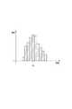
複数の画素の輝度値のばらつき度合いは、空間軸方向における複数の画素の輝度値のばらつき度合いに基づいて求められる。例えば図4に示す例において、空間軸方向における複数の画素の輝度値のばらつき度合いは、空間軸方向において同じ位置の画素の時間軸方向における輝度値の平均値(平均輝度)を求め(時間的な平均輝度を求め)、各平均輝度を空間軸方向における複数の画素単位で比較することにより求めることができる。ばらつき度は、標準偏差や、最大値及び最小値の差等から求める。より詳細には、ばらつき度は、平均輝度分布の最頻度に対する誤差(%)に基づいて求められる。例えば図5に示すように、時間平均をした空間軸方向における複数の画素の輝度値として、輝度fbが最頻度の輝度値(複数の画素の輝度値として最も多い輝度値)であったとすると、当該輝度fbに対する輝度値の誤差が、最頻度に対する輝度値の誤差とされる。なお、ばらつき度は、平均値又は中間値に対する誤差(%)に基づいて求めてもよい。すなわち、時間平均をした空間軸方向における複数の画素の平均値又は中間値に対する誤差に基づいてばらつき度を求めてもよい。また、ばらつき度は、時間平均をした空間軸方向における複数の画素の最大値と最小値との差に基づいて求めてもよい。 The degree of variation of the luminance values of the plurality of pixels is obtained based on the degree of variation of the luminance values of the plurality of pixels in the spatial axis direction. For example, in the example shown in FIG. 4, the degree of variation in the luminance value of a plurality of pixels in the spatial axis direction is obtained by calculating an average value (average luminance) of luminance values in the temporal axis direction of pixels at the same position in the spatial axis direction (temporal). The average luminance can be obtained by comparing each average luminance in units of a plurality of pixels in the spatial axis direction. The degree of variation is obtained from the standard deviation or the difference between the maximum value and the minimum value. More specifically, the degree of variation is obtained based on an error (%) with respect to the maximum frequency of the average luminance distribution. For example, as shown in FIG. 5, assuming that the luminance fb is the most frequent luminance value (the highest luminance value as the luminance value of the plurality of pixels) as the luminance value of the plurality of pixels in the spatial axis direction averaged over time. The error of the luminance value with respect to the luminance fb is the error of the luminance value with respect to the maximum frequency. The degree of variation may be obtained based on an error (%) with respect to the average value or the intermediate value. That is, the degree of variation may be obtained based on an error with respect to an average value or an intermediate value of a plurality of pixels in the spatial axis direction obtained by time averaging. The degree of variation may be obtained based on the difference between the maximum value and the minimum value of a plurality of pixels in the spatial axis direction obtained by time averaging.
また、複数の画素の輝度値のばらつき度合いは、時間軸方向における複数の画素の輝度値のばらつき度合いにより求められるものであってもよい。この場合には、同じ時間に取得された画素の輝度値の平均値(平均輝度)を求め(空間的な平均輝度を求め)、各平均輝度を時間軸方向における複数の画素単位で比較することにより求めることができる。なお、本実施形態における輝度値は、アナログ値であってもデジタル値であってもよい。 Further, the degree of variation of the luminance values of the plurality of pixels may be obtained from the degree of variation of the luminance values of the plurality of pixels in the time axis direction. In this case, the average value (average luminance) of the luminance values of the pixels acquired at the same time is obtained (spatial average luminance is obtained), and each average luminance is compared in units of a plurality of pixels in the time axis direction. It can ask for. Note that the luminance value in the present embodiment may be an analog value or a digital value.
上述した、アンプ制御部18による撮像条件に基づく設定増幅率の設定は、例えば撮像条件のパラメータ(輝度値のばらつき度合い等)に対応するテーブルに基づいて行われるものであってもよい。すなわち、アンプ制御部18は、撮像条件のパラメータに対応するテーブルを予め記憶しておき、該テーブルを用いて、設定増幅率として高ゲイン(第1の増幅率)を設定するか、低ゲイン(第2の増幅率)を設定するかを決定してもよい。また、アンプ制御部18による撮像条件に基づく設定増幅率の設定は、例えば撮像条件のパラメータ(輝度値のばらつき度合い等)に対応する閾値に基づいて行われるものであってもよい。すなわち、アンプ制御部18は、撮像条件のパラメータに対応する閾値を予め記憶しておき、該閾値を上回るか否かに応じて、設定増幅率として高ゲイン(第1の増幅率)を設定するか、低ゲイン(第2の増幅率)を設定するかを決定してもよい。 The setting of the set amplification factor based on the imaging condition by the
次に、画像取得装置1を用いた画像取得方法について説明する。本画像取得方法は、搬送方向TDに搬送される対象物FのX線透過画像を取得する画像取得方法である。本画像取得方法では、最初に、X線源であるX線照射器50によりX線が出力される(X線を出力するステップ)。また、ベルトコンベア60により対象物Fが搬送方向TDに搬送される(対象物Fを搬送方向TDに搬送するステップ)。つづいて、X線検出カメラ10のシンチレータ11a,11bにより、対象物Fを透過したX線がシンチレーション光に変換される(シンチレーション光に変換するステップ)。つづいて、ラインスキャンカメラ12a,12bによりシンチレーション光が検出され検出信号が出力される(検出信号を出力するステップ)。つづいて、アンプ14a,14bにより、所定の設定増幅率にて検出信号が増幅され増幅信号が出力される(増幅信号を出力するステップ)。なお、少なくとも、当該増幅信号を出力するステップよりも前に、アンプ制御部18により、所定の撮像条件に基づき、高ゲイン(第1の増幅率)、又は、高ゲインよりも低い増幅率である低ゲイン(第2の増幅率)のいずれか一方が設定増幅率として設定されている。最後に、制御装置20により、増幅信号に基づきX線透過画像が生成される。以上が、画像取得装置1を用いた画像取得方法である。 Next, an image acquisition method using the
次に、上述した本実施形態に係る画像取得装置1の作用効果について説明する。 Next, the effect of the
本実施形態に係る画像取得装置1では、対象物Fを透過したX線に基づく検出信号が所定の設定増幅率にて増幅されて、X線透過画像が生成される。そして、設定増幅率は、所定の撮像条件に基づき、高ゲイン(第1の増幅率)又は第1の増幅率よりも低い増幅率である低ゲイン(第2の増幅率)のいずれか一方が設定される。鮮明なX線透過画像を生成するために適切な増幅率は撮像条件によって変わるものであるところ、撮像条件に応じて設定増幅率が選択されることにより、鮮明なX線透過画像を生成することができる。 In the
また、画像取得装置1のラインスキャンカメラ12a,12bは、搬送方向TDと交差する方向に並列した複数のラインセンサを有している。複数のラインセンサにより、対象物Fに係るシンチレーション光を確実に検出することができる。 Further, the
また、撮像条件をX線透過画像の複数の画素の輝度値に関するパラメータとすることにより、アンプ制御部18は、設定増幅率を適切に設定することができる。より詳細には、輝度値に関するパラメータはX線透過画像の複数の画素の輝度値の統計値であり、当該統計値は、複数の画素の輝度値のばらつき度合いである。ベルトコンベア60により搬送される対象物FのX線透過画像を取得する場合、対象物Fを構成する成分等によって、X線検出カメラ10に入射するX線量は大きく異なる。例えば対象物FのうちX線を透過しにくい成分で構成される部分においては、X線検出カメラ10に入射するX線量は少なくなる。一方、対象物FのうちX線を透過しやすい成分で構成される部分においては、X線検出カメラ10に入射するX線量は多くなる。このようなX線量の違い等によって、X線透過画像における複数の画素の輝度値にばらつきが生じる。輝度値のばらつき度合いが大きい場合には、低ゲインを設定することによりX線透過画像が鮮明になる。よって、複数の画素の輝度値のばらつきを撮像条件として、アンプ制御部18が高ゲイン又は低ゲインを設定することにより、鮮明な(SNの向上が図られた)X線透過画像を生成することができる。なお、輝度値のばらつき度合いが小さい場合には、アンプ制御部18が高ゲインを設定することにより信号量を増やし長寿命化を図ることができる。アンプ制御部18の設定変更によって信号量を増やすため、X線照射器50の出力パラメータである管電圧や管電流を増やす操作は必要としない。X線照射器50の寿命は、出力パラメータである管電圧や管電流によって影響を受けることが分かっており、それらの値が大きくなるとX線照射器50の寿命は短くなる。アンプ制御部18によるゲインの設定変更によって信号量を増やした場合、X線照射器50の出力を大きくすることなく信号量を増やすことができるため、X線照射器50の寿命を長くすることができる。また、ラインスキャンカメラ12a,12bやシンチレータ11a,11bの寿命は、X線の被曝量に影響を受けることが分かっている。従って、アンプ制御部18によるゲインの設定変更によって信号量を増やした場合、X線照射器50の出力パラメータを大きくすることなく、信号量を増やすことができるため、ラインスキャンカメラ12a,12bやシンチレータ11a,11bの寿命を長くすることができる。 Moreover, the
また、撮像条件が、制御装置20により生成されたX線透過画像に基づいて設定されたものであるので、撮像条件を容易に設定することができる。さらに、撮像条件の設定に係るX線透過画像が、アンプ制御部18により高ゲイン(第1の増幅率)設定とされた環境下で生成されたものであるので、X線透過画像の複数の画素の輝度値に関するパラメータが明確になり、輝度値に関するパラメータを容易に特定することができる。これにより、X線透過画像に基づいて、より容易且つ適切に撮像条件を設定することができる。 Moreover, since the imaging condition is set based on the X-ray transmission image generated by the
また、X線透過画像の複数の画素はX線透過画像の異なる空間に係る複数の画素である。これにより、X線透過画像の異なる空間に係る複数の画素のパラメータを考慮して、設定増幅率を適切に設定することができる。 In addition, the plurality of pixels of the X-ray transmission image are a plurality of pixels related to different spaces of the X-ray transmission image. Thereby, the set amplification factor can be appropriately set in consideration of parameters of a plurality of pixels related to different spaces of the X-ray transmission image.
また、X線透過画像の複数の画素はX線透過画像の異なる時間に係る複数の画素であってもよい。この場合には、X線透過画像の異なる時間に係る複数の画素のパラメータを考慮して、設定増幅率を適切に設定することができる。 The plurality of pixels of the X-ray transmission image may be a plurality of pixels related to different times of the X-ray transmission image. In this case, the set amplification factor can be appropriately set in consideration of parameters of a plurality of pixels related to different times of the X-ray transmission image.
また、撮像条件は、X線照射器50の出力パラメータ、具体的には、X線照射器50から出力されるX線に係る管電圧及び管電流に基づくものであってもよい。X線照射器50の管電圧が高く管電流が低い場合には、複数の画素の輝度値がばらつく傾向にある。そのため、制御装置20により撮像条件とされたX線に係る管電圧が所定値よりも高く、管電流が所定値よりも低い場合には、アンプ制御部18は、当該撮像条件に基づき、設定増幅率を低ゲイン(第2の増幅率)に設定する。一方、制御装置20により撮像条件とされたX線に係る管電圧が所定値よりも低く、管電流が所定値よりも高い場合には、アンプ制御部18は、当該撮像条件に基づき、設定増幅率を高ゲイン(第1の増幅率)に設定する。これにより、設定増幅率を適切に設定することができる。 Further, the imaging conditions may be based on the output parameters of the
また、アンプ制御部18が、撮像条件のパラメータに対応するテーブルを有し、該テーブルを用いて、設定増幅率として高ゲイン(第1の増幅率)を設定するか、低ゲイン(第2の増幅率)を設定するかを決定してもよい。これにより、設定増幅率の設定を確実且つ簡易に行うことができる。 In addition, the
また、アンプ制御部18が、撮像条件のパラメータに対応する閾値を有し、該閾値を上回るか否かに応じて、設定増幅率として高ゲイン(第1の増幅率)を設定するか、低ゲイン(第2の増幅率)を設定するかを決定してもよい。これにより、設定増幅率の設定を確実且つ簡易に行うことができる。 Further, the
以上、本発明の好適な実施形態について説明したが、本発明は上記実施形態に限定されるものではない。 The preferred embodiment of the present invention has been described above, but the present invention is not limited to the above embodiment.
例えば、X線検出カメラはデュアルラインX線カメラであるとして説明したがこれに限定されず、シングルラインX線カメラや、デュアルエナジX線カメラ、TDI(Time Delay Integration)スキャンX線カメラであってもよい。 For example, the X-ray detection camera has been described as being a dual-line X-ray camera, but is not limited thereto, and is a single-line X-ray camera, a dual energy X-ray camera, or a TDI (Time Delay Integration) scan X-ray camera. Also good.
1…画像取得装置、10…X線検出カメラ、11a,11b…シンチレータ、12a,12b…ラインスキャンカメラ、14a,14b…アンプ、14x…電流電圧変換アンプ、14y…電圧増幅アンプ、18…アンプ制御部、20…制御装置、50…X線照射器、F…対象物、TD…搬送方向。
DESCRIPTION OF
Claims (13)
Translated fromJapanese放射線を出力する放射線源と、
前記対象物を前記搬送方向に搬送する搬送手段と、
前記対象物を透過した放射線をシンチレーション光に変換する変換部、前記シンチレーション光を検出し検出信号を出力するラインスキャンカメラ部、及び、所定の設定増幅率にて前記検出信号を増幅し該増幅信号を出力する増幅部を有する検出手段と、
前記増幅信号に基づいて、放射線画像を生成する画像生成部と、
所定の撮像条件に基づいて、第1の増幅率又は第1の増幅率よりも低い増幅率である第2の増幅率のいずれか一方を前記設定増幅率として設定する設定手段と、を備える画像取得装置。An image acquisition device for acquiring a radiographic image of an object conveyed in a conveyance direction,
A radiation source that outputs radiation;
Conveying means for conveying the object in the conveying direction;
A conversion unit that converts radiation transmitted through the object into scintillation light; a line scan camera unit that detects the scintillation light and outputs a detection signal; and amplifies the detection signal at a predetermined amplification factor. Detecting means having an amplifying unit for outputting
An image generation unit for generating a radiation image based on the amplified signal;
An image including: a setting unit configured to set, as the set amplification factor, either the first amplification factor or a second amplification factor that is lower than the first amplification factor based on a predetermined imaging condition; Acquisition device.
前記対象物を透過した放射線をシンチレーション光に変換し、ラインスキャンカメラ部により前記シンチレーション光を検出し検出信号を出力するステップと、
所定の撮像条件に基づいて、第1の増幅率又は第1の増幅率よりも低い増幅率である第2の増幅率のいずれか一方を設定増幅率として設定するステップと、
前記設定増幅率にて前記検出信号を増幅し増幅信号を出力するステップと、
前記増幅信号に基づいて放射線画像を生成するステップと、を備える画像取得方法。
An image acquisition method for acquiring a radiographic image of an object conveyed in a conveyance direction,
Converting the radiation transmitted through the object into scintillation light, detecting the scintillation light by a line scan camera unit, and outputting a detection signal;
Setting one of the first gain and the second gain that is lower than the first gain as the set gain based on a predetermined imaging condition;
Amplifying the detection signal at the set amplification factor and outputting an amplified signal;
Generating a radiation image based on the amplified signal.
Priority Applications (8)
| Application Number | Priority Date | Filing Date | Title |
|---|---|---|---|
| JP2014089350AJP6442154B2 (en) | 2014-04-23 | 2014-04-23 | Image acquisition apparatus and image acquisition method |
| ES15782767TES2948798T3 (en) | 2014-04-23 | 2015-02-02 | Image acquisition device and image acquisition method |
| EP15782767.6AEP3136087B1 (en) | 2014-04-23 | 2015-02-02 | Image acquisition device and image acquisition method |
| FIEP15782767.6TFI3136087T3 (en) | 2014-04-23 | 2015-02-02 | Image acquisition device and image acquisition method |
| PCT/JP2015/052875WO2015162963A1 (en) | 2014-04-23 | 2015-02-02 | Image acquisition device and image acquisition method |
| CN201580020701.4ACN106233127B (en) | 2014-04-23 | 2015-02-02 | Image acquisition device and image acquisition method |
| KR1020167031780AKR102277829B1 (en) | 2014-04-23 | 2015-02-02 | Image acquisition device and image acquisition method |
| US15/305,148US10267751B2 (en) | 2014-04-23 | 2015-02-02 | Image acquisition device and image acquisition method |
Applications Claiming Priority (1)
| Application Number | Priority Date | Filing Date | Title |
|---|---|---|---|
| JP2014089350AJP6442154B2 (en) | 2014-04-23 | 2014-04-23 | Image acquisition apparatus and image acquisition method |
Publications (2)
| Publication Number | Publication Date |
|---|---|
| JP2015206773A JP2015206773A (en) | 2015-11-19 |
| JP6442154B2true JP6442154B2 (en) | 2018-12-19 |
Family
ID=54332137
Family Applications (1)
| Application Number | Title | Priority Date | Filing Date |
|---|---|---|---|
| JP2014089350AActiveJP6442154B2 (en) | 2014-04-23 | 2014-04-23 | Image acquisition apparatus and image acquisition method |
Country Status (8)
| Country | Link |
|---|---|
| US (1) | US10267751B2 (en) |
| EP (1) | EP3136087B1 (en) |
| JP (1) | JP6442154B2 (en) |
| KR (1) | KR102277829B1 (en) |
| CN (1) | CN106233127B (en) |
| ES (1) | ES2948798T3 (en) |
| FI (1) | FI3136087T3 (en) |
| WO (1) | WO2015162963A1 (en) |
Families Citing this family (45)
| Publication number | Priority date | Publication date | Assignee | Title |
|---|---|---|---|---|
| US10241158B2 (en) | 2015-02-04 | 2019-03-26 | Lockheed Martin Corporation | Apparatus and method for estimating absolute axes' orientations for a magnetic detection system |
| US9910105B2 (en) | 2014-03-20 | 2018-03-06 | Lockheed Martin Corporation | DNV magnetic field detector |
| US10012704B2 (en) | 2015-11-04 | 2018-07-03 | Lockheed Martin Corporation | Magnetic low-pass filter |
| US10168393B2 (en) | 2014-09-25 | 2019-01-01 | Lockheed Martin Corporation | Micro-vacancy center device |
| WO2015157290A1 (en) | 2014-04-07 | 2015-10-15 | Lockheed Martin Corporation | Energy efficient controlled magnetic field generator circuit |
| WO2016118756A1 (en) | 2015-01-23 | 2016-07-28 | Lockheed Martin Corporation | Apparatus and method for high sensitivity magnetometry measurement and signal processing in a magnetic detection system |
| GB2551090A (en) | 2015-02-04 | 2017-12-06 | Lockheed Corp | Apparatus and method for recovery of three dimensional magnetic field from a magnetic detection system |
| WO2017087013A1 (en) | 2015-11-20 | 2017-05-26 | Lockheed Martin Corporation | Apparatus and method for closed loop processing for a magnetic detection system |
| WO2017095454A1 (en) | 2015-12-01 | 2017-06-08 | Lockheed Martin Corporation | Communication via a magnio |
| WO2017123261A1 (en) | 2016-01-12 | 2017-07-20 | Lockheed Martin Corporation | Defect detector for conductive materials |
| WO2017127096A1 (en) | 2016-01-21 | 2017-07-27 | Lockheed Martin Corporation | Diamond nitrogen vacancy sensor with dual rf sources |
| WO2017127079A1 (en) | 2016-01-21 | 2017-07-27 | Lockheed Martin Corporation | Ac vector magnetic anomaly detection with diamond nitrogen vacancies |
| GB2562958A (en) | 2016-01-21 | 2018-11-28 | Lockheed Corp | Magnetometer with a light emitting diode |
| WO2017127098A1 (en) | 2016-01-21 | 2017-07-27 | Lockheed Martin Corporation | Diamond nitrogen vacancy sensed ferro-fluid hydrophone |
| US10571530B2 (en) | 2016-05-31 | 2020-02-25 | Lockheed Martin Corporation | Buoy array of magnetometers |
| US10345396B2 (en) | 2016-05-31 | 2019-07-09 | Lockheed Martin Corporation | Selected volume continuous illumination magnetometer |
| US10359479B2 (en) | 2017-02-20 | 2019-07-23 | Lockheed Martin Corporation | Efficient thermal drift compensation in DNV vector magnetometry |
| US10281550B2 (en) | 2016-11-14 | 2019-05-07 | Lockheed Martin Corporation | Spin relaxometry based molecular sequencing |
| US10371765B2 (en) | 2016-07-11 | 2019-08-06 | Lockheed Martin Corporation | Geolocation of magnetic sources using vector magnetometer sensors |
| US10317279B2 (en) | 2016-05-31 | 2019-06-11 | Lockheed Martin Corporation | Optical filtration system for diamond material with nitrogen vacancy centers |
| US10527746B2 (en) | 2016-05-31 | 2020-01-07 | Lockheed Martin Corporation | Array of UAVS with magnetometers |
| US10145910B2 (en)* | 2017-03-24 | 2018-12-04 | Lockheed Martin Corporation | Photodetector circuit saturation mitigation for magneto-optical high intensity pulses |
| US10338163B2 (en) | 2016-07-11 | 2019-07-02 | Lockheed Martin Corporation | Multi-frequency excitation schemes for high sensitivity magnetometry measurement with drift error compensation |
| US20170343621A1 (en) | 2016-05-31 | 2017-11-30 | Lockheed Martin Corporation | Magneto-optical defect center magnetometer |
| US10345395B2 (en) | 2016-12-12 | 2019-07-09 | Lockheed Martin Corporation | Vector magnetometry localization of subsurface liquids |
| US10330744B2 (en) | 2017-03-24 | 2019-06-25 | Lockheed Martin Corporation | Magnetometer with a waveguide |
| US10228429B2 (en) | 2017-03-24 | 2019-03-12 | Lockheed Martin Corporation | Apparatus and method for resonance magneto-optical defect center material pulsed mode referencing |
| US10677953B2 (en) | 2016-05-31 | 2020-06-09 | Lockheed Martin Corporation | Magneto-optical detecting apparatus and methods |
| US10274550B2 (en) | 2017-03-24 | 2019-04-30 | Lockheed Martin Corporation | High speed sequential cancellation for pulsed mode |
| US10408890B2 (en) | 2017-03-24 | 2019-09-10 | Lockheed Martin Corporation | Pulsed RF methods for optimization of CW measurements |
| US10371760B2 (en) | 2017-03-24 | 2019-08-06 | Lockheed Martin Corporation | Standing-wave radio frequency exciter |
| US10379174B2 (en) | 2017-03-24 | 2019-08-13 | Lockheed Martin Corporation | Bias magnet array for magnetometer |
| US10459041B2 (en) | 2017-03-24 | 2019-10-29 | Lockheed Martin Corporation | Magnetic detection system with highly integrated diamond nitrogen vacancy sensor |
| US10338164B2 (en) | 2017-03-24 | 2019-07-02 | Lockheed Martin Corporation | Vacancy center material with highly efficient RF excitation |
| US10110777B1 (en)* | 2017-04-13 | 2018-10-23 | Microtek International Inc. | Image scanning apparatus |
| JP7057630B2 (en)* | 2017-06-23 | 2022-04-20 | 浜松ホトニクス株式会社 | Radiation detector |
| JP6717784B2 (en)* | 2017-06-30 | 2020-07-08 | アンリツインフィビス株式会社 | Article inspection apparatus and calibration method thereof |
| JP6920520B2 (en)* | 2018-03-09 | 2021-08-18 | 浜松ホトニクス株式会社 | Image acquisition system and image acquisition method |
| JP6738363B2 (en) | 2018-03-09 | 2020-08-12 | 浜松ホトニクス株式会社 | Image acquisition system and image acquisition method |
| JP6569069B1 (en)* | 2018-03-14 | 2019-09-04 | 株式会社 システムスクエア | Inspection device |
| JP7209329B2 (en)* | 2018-06-28 | 2023-01-20 | 株式会社 システムスクエア | inspection equipment |
| WO2021210618A1 (en)* | 2020-04-16 | 2021-10-21 | 浜松ホトニクス株式会社 | Radiographic image processing method, trained model, radiographic image processing module, radiographic image processing program, and radiographic image processing system |
| CN115427795A (en)* | 2020-04-16 | 2022-12-02 | 浜松光子学株式会社 | Radiation image acquisition device, radiation image acquisition system, and radiation image acquisition method |
| JP6985557B2 (en)* | 2020-07-17 | 2021-12-22 | 浜松ホトニクス株式会社 | Image acquisition system and image acquisition method |
| JP7250891B2 (en)* | 2020-07-17 | 2023-04-03 | 浜松ホトニクス株式会社 | Image acquisition system and image acquisition method |
Family Cites Families (26)
| Publication number | Priority date | Publication date | Assignee | Title |
|---|---|---|---|---|
| CN85107860A (en) | 1985-04-03 | 1986-10-01 | 海曼股份公司 | The X-ray scanner |
| JP3387760B2 (en) | 1996-12-25 | 2003-03-17 | 株式会社日立メディコ | X-ray luggage inspection device |
| US6163029A (en) | 1997-09-22 | 2000-12-19 | Kabushiki Kaisha Toshiba | Radiation detector, radiation detecting method and X-ray diagnosing apparatus with same radiation detector |
| JPH1194532A (en) | 1997-09-22 | 1999-04-09 | Toshiba Corp | X-ray solid state detector and X-ray diagnostic apparatus |
| DE19945763A1 (en)* | 1999-09-24 | 2001-03-29 | Philips Corp Intellectual Pty | Computer tomograph |
| US6486808B1 (en)* | 2001-10-16 | 2002-11-26 | Varian Medical Systems | Data signal amplifier with automatically controllable dynamic signal range |
| JP3757946B2 (en) | 2003-03-18 | 2006-03-22 | 株式会社島津製作所 | Radiation imaging device |
| US6901135B2 (en)* | 2003-08-28 | 2005-05-31 | Bio-Imaging Research, Inc. | System for extending the dynamic gain of an X-ray detector |
| JP4583155B2 (en)* | 2004-12-13 | 2010-11-17 | Hoya株式会社 | Defect inspection method and system, and photomask manufacturing method |
| JP2006319414A (en) | 2005-05-10 | 2006-11-24 | Shimadzu Corp | Light or radiation detector and light or radiation imaging apparatus provided with the same |
| BRPI0618680B1 (en)* | 2005-11-16 | 2018-06-05 | Ishida Co., Ltd. | X-RAY INSPECTION DEVICE |
| CN1936555A (en) | 2006-09-25 | 2007-03-28 | 天津安信通科技有限公司 | Damage-free detection system for strong conveying belt |
| JP4825116B2 (en)* | 2006-11-22 | 2011-11-30 | 浜松ホトニクス株式会社 | Solid-state imaging device and imaging method |
| JP2008224448A (en) | 2007-03-13 | 2008-09-25 | Omron Corp | X-ray inspection method and X-ray inspection apparatus |
| JP5148230B2 (en)* | 2007-09-26 | 2013-02-20 | 株式会社イシダ | X-ray inspection equipment |
| JP2009085627A (en) | 2007-09-27 | 2009-04-23 | Ishida Co Ltd | X-ray line sensor module and x-ray foreign matter inspection device |
| JP5559471B2 (en) | 2008-11-11 | 2014-07-23 | 浜松ホトニクス株式会社 | Radiation detection apparatus, radiation image acquisition system, radiation inspection system, and radiation detection method |
| JP5368772B2 (en) | 2008-11-11 | 2013-12-18 | 浜松ホトニクス株式会社 | Radiation detection apparatus, radiation image acquisition system, and radiation detection method |
| JP5203291B2 (en)* | 2009-05-18 | 2013-06-05 | 株式会社ジャパンディスプレイウェスト | Display device and electronic device |
| JP5457118B2 (en) | 2009-09-18 | 2014-04-02 | 浜松ホトニクス株式会社 | Radiation detector |
| US8717474B2 (en)* | 2009-12-04 | 2014-05-06 | Canon Kabushiki Kaisha | Imaging apparatus and method for driving the same |
| JP5246187B2 (en) | 2010-03-15 | 2013-07-24 | オムロン株式会社 | X-ray inspection apparatus, X-ray inspection method and program |
| CN103168252B (en) | 2010-10-26 | 2016-05-18 | 富士胶片株式会社 | Radiographic imaging device and radiation image image pickup method |
| US20130256542A1 (en) | 2012-03-28 | 2013-10-03 | Luxen Technologies, Inc. | Programmable readout integrated circuit for an ionizing radiation sensor |
| JP6218365B2 (en)* | 2012-08-08 | 2017-10-25 | 東芝メディカルシステムズ株式会社 | Medical diagnostic imaging equipment |
| JP5890286B2 (en)* | 2012-09-18 | 2016-03-22 | 富士フイルム株式会社 | Radiation image detection device |
- 2014
- 2014-04-23JPJP2014089350Apatent/JP6442154B2/enactiveActive
- 2015
- 2015-02-02CNCN201580020701.4Apatent/CN106233127B/enactiveActive
- 2015-02-02ESES15782767Tpatent/ES2948798T3/enactiveActive
- 2015-02-02FIFIEP15782767.6Tpatent/FI3136087T3/enactive
- 2015-02-02KRKR1020167031780Apatent/KR102277829B1/enactiveActive
- 2015-02-02EPEP15782767.6Apatent/EP3136087B1/enactiveActive
- 2015-02-02WOPCT/JP2015/052875patent/WO2015162963A1/enactiveApplication Filing
- 2015-02-02USUS15/305,148patent/US10267751B2/enactiveActive
Also Published As
| Publication number | Publication date |
|---|---|
| FI3136087T3 (en) | 2023-08-28 |
| CN106233127A (en) | 2016-12-14 |
| EP3136087A4 (en) | 2017-11-01 |
| US20170038314A1 (en) | 2017-02-09 |
| WO2015162963A1 (en) | 2015-10-29 |
| KR102277829B1 (en) | 2021-07-16 |
| JP2015206773A (en) | 2015-11-19 |
| CN106233127B (en) | 2019-05-21 |
| KR20160146827A (en) | 2016-12-21 |
| US10267751B2 (en) | 2019-04-23 |
| EP3136087A1 (en) | 2017-03-01 |
| ES2948798T3 (en) | 2023-09-19 |
| EP3136087B1 (en) | 2023-06-07 |
Similar Documents
| Publication | Publication Date | Title |
|---|---|---|
| JP6442154B2 (en) | Image acquisition apparatus and image acquisition method | |
| JP6243504B2 (en) | Radiation imaging apparatus, control method therefor, and radiation image detection apparatus | |
| JP5890286B2 (en) | Radiation image detection device | |
| JP6209683B2 (en) | Detection device for detecting photons and method therefor | |
| US10064585B2 (en) | Photon detecting element, photon detecting device, and radiation analyzing device | |
| US10074679B2 (en) | Radiation image detecting device | |
| US9958557B2 (en) | Photon counting apparatus and method, and radiographic imaging apparatus comprising the same | |
| CN102135626A (en) | Circuit arrangement for counting x-ray radiation x-ray quanta by way of quanta-counting detectors, and also an application-specific integrated circuit and an emitter-detector system | |
| EP2549297A3 (en) | Radiographic detector including trap occupancy change monitor and feedback, imaging apparatus and methods using the same | |
| CN109521455B (en) | X-ray image detector for realizing automatic gain switching and method thereof | |
| JP2016214394A (en) | Radiographic apparatus, radiographic method, and program | |
| US20140355739A1 (en) | Radiographic imaging apparatus and radiographic image generation method | |
| US6718011B2 (en) | Planar image detector for electromagnetic rays, particularly X-rays | |
| CN115398215A (en) | Radiological image processing method, learned model, radiological image processing module, radiological image processing program, and radiological image processing system | |
| JP2011089965A (en) | Article inspection device | |
| Yun et al. | Detective quantum efficiency of a phosphor-coupled photodiode array detector for use in digital X-ray tomosynthesis systems | |
| US9864068B2 (en) | Circuit, photon detector, and radiation analyzer | |
| WO2017085905A1 (en) | Radiation imaging system, signal processing apparatus, and signal processing method for radiographic image | |
| US20150103973A1 (en) | X-ray system with multiple dynamic range selections | |
| JP2017538470A5 (en) | ||
| US20140332671A1 (en) | Photon counting controller, radiographic imaging apparatus, and control method of photon counting controller | |
| US10426415B2 (en) | Method for receiving energy -selective image data, X-ray detector and X-ray system | |
| JP2013162822A5 (en) | ||
| KR101220883B1 (en) | X-ray readout integrated circuit and method for detecting x-rays with adjustable amplification gain and x-ray sensor using the same | |
| CN115427794A (en) | Radiological image processing method, learned model, radiological image processing module, radiological image processing program, radiological image processing system, and machine learning method |
Legal Events
| Date | Code | Title | Description |
|---|---|---|---|
| A621 | Written request for application examination | Free format text:JAPANESE INTERMEDIATE CODE: A621 Effective date:20170322 | |
| A131 | Notification of reasons for refusal | Free format text:JAPANESE INTERMEDIATE CODE: A131 Effective date:20180220 | |
| A601 | Written request for extension of time | Free format text:JAPANESE INTERMEDIATE CODE: A601 Effective date:20180410 | |
| TRDD | Decision of grant or rejection written | ||
| A01 | Written decision to grant a patent or to grant a registration (utility model) | Free format text:JAPANESE INTERMEDIATE CODE: A01 Effective date:20181120 | |
| A61 | First payment of annual fees (during grant procedure) | Free format text:JAPANESE INTERMEDIATE CODE: A61 Effective date:20181126 | |
| R150 | Certificate of patent or registration of utility model | Ref document number:6442154 Country of ref document:JP Free format text:JAPANESE INTERMEDIATE CODE: R150 | |
| R250 | Receipt of annual fees | Free format text:JAPANESE INTERMEDIATE CODE: R250 | |
| R250 | Receipt of annual fees | Free format text:JAPANESE INTERMEDIATE CODE: R250 |