JP6440949B2 - Irrigation ablation catheter having an irrigation port with reduced fluid resistance - Google Patents
Irrigation ablation catheter having an irrigation port with reduced fluid resistanceDownload PDFInfo
- Publication number
- JP6440949B2 JP6440949B2JP2014043592AJP2014043592AJP6440949B2JP 6440949 B2JP6440949 B2JP 6440949B2JP 2014043592 AJP2014043592 AJP 2014043592AJP 2014043592 AJP2014043592 AJP 2014043592AJP 6440949 B2JP6440949 B2JP 6440949B2
- Authority
- JP
- Japan
- Prior art keywords
- fluid
- tip electrode
- port
- diameter
- shell
- Prior art date
- Legal status (The legal status is an assumption and is not a legal conclusion. Google has not performed a legal analysis and makes no representation as to the accuracy of the status listed.)
- Active
Links
Images


Classifications
- A—HUMAN NECESSITIES
- A61—MEDICAL OR VETERINARY SCIENCE; HYGIENE
- A61B—DIAGNOSIS; SURGERY; IDENTIFICATION
- A61B18/00—Surgical instruments, devices or methods for transferring non-mechanical forms of energy to or from the body
- A61B18/04—Surgical instruments, devices or methods for transferring non-mechanical forms of energy to or from the body by heating
- A61B18/12—Surgical instruments, devices or methods for transferring non-mechanical forms of energy to or from the body by heating by passing a current through the tissue to be heated, e.g. high-frequency current
- A61B18/14—Probes or electrodes therefor
- A61B18/1492—Probes or electrodes therefor having a flexible, catheter-like structure, e.g. for heart ablation
- A—HUMAN NECESSITIES
- A61—MEDICAL OR VETERINARY SCIENCE; HYGIENE
- A61B—DIAGNOSIS; SURGERY; IDENTIFICATION
- A61B18/00—Surgical instruments, devices or methods for transferring non-mechanical forms of energy to or from the body
- A61B2018/00005—Cooling or heating of the probe or tissue immediately surrounding the probe
- A61B2018/00011—Cooling or heating of the probe or tissue immediately surrounding the probe with fluids
- A61B2018/00029—Cooling or heating of the probe or tissue immediately surrounding the probe with fluids open
- A—HUMAN NECESSITIES
- A61—MEDICAL OR VETERINARY SCIENCE; HYGIENE
- A61B—DIAGNOSIS; SURGERY; IDENTIFICATION
- A61B18/00—Surgical instruments, devices or methods for transferring non-mechanical forms of energy to or from the body
- A61B2018/00315—Surgical instruments, devices or methods for transferring non-mechanical forms of energy to or from the body for treatment of particular body parts
- A61B2018/00345—Vascular system
- A61B2018/00351—Heart
- A61B2018/00357—Endocardium
- A—HUMAN NECESSITIES
- A61—MEDICAL OR VETERINARY SCIENCE; HYGIENE
- A61B—DIAGNOSIS; SURGERY; IDENTIFICATION
- A61B18/00—Surgical instruments, devices or methods for transferring non-mechanical forms of energy to or from the body
- A61B2018/00571—Surgical instruments, devices or methods for transferring non-mechanical forms of energy to or from the body for achieving a particular surgical effect
- A61B2018/00577—Ablation
- A—HUMAN NECESSITIES
- A61—MEDICAL OR VETERINARY SCIENCE; HYGIENE
- A61B—DIAGNOSIS; SURGERY; IDENTIFICATION
- A61B18/00—Surgical instruments, devices or methods for transferring non-mechanical forms of energy to or from the body
- A61B2018/00636—Sensing and controlling the application of energy
- A61B2018/00773—Sensed parameters
- A61B2018/00791—Temperature
- A61B2018/00821—Temperature measured by a thermocouple
- A—HUMAN NECESSITIES
- A61—MEDICAL OR VETERINARY SCIENCE; HYGIENE
- A61B—DIAGNOSIS; SURGERY; IDENTIFICATION
- A61B18/00—Surgical instruments, devices or methods for transferring non-mechanical forms of energy to or from the body
- A61B2018/00636—Sensing and controlling the application of energy
- A61B2018/00773—Sensed parameters
- A61B2018/00839—Bioelectrical parameters, e.g. ECG, EEG
- A—HUMAN NECESSITIES
- A61—MEDICAL OR VETERINARY SCIENCE; HYGIENE
- A61B—DIAGNOSIS; SURGERY; IDENTIFICATION
- A61B34/00—Computer-aided surgery; Manipulators or robots specially adapted for use in surgery
- A61B34/20—Surgical navigation systems; Devices for tracking or guiding surgical instruments, e.g. for frameless stereotaxis
- A61B2034/2046—Tracking techniques
- A61B2034/2051—Electromagnetic tracking systems
- A—HUMAN NECESSITIES
- A61—MEDICAL OR VETERINARY SCIENCE; HYGIENE
- A61B—DIAGNOSIS; SURGERY; IDENTIFICATION
- A61B2218/00—Details of surgical instruments, devices or methods for transferring non-mechanical forms of energy to or from the body
- A61B2218/001—Details of surgical instruments, devices or methods for transferring non-mechanical forms of energy to or from the body having means for irrigation and/or aspiration of substances to and/or from the surgical site
- A61B2218/002—Irrigation
- A—HUMAN NECESSITIES
- A61—MEDICAL OR VETERINARY SCIENCE; HYGIENE
- A61M—DEVICES FOR INTRODUCING MEDIA INTO, OR ONTO, THE BODY; DEVICES FOR TRANSDUCING BODY MEDIA OR FOR TAKING MEDIA FROM THE BODY; DEVICES FOR PRODUCING OR ENDING SLEEP OR STUPOR
- A61M25/00—Catheters; Hollow probes
- A61M25/01—Introducing, guiding, advancing, emplacing or holding catheters
- A61M25/0105—Steering means as part of the catheter or advancing means; Markers for positioning
- A61M25/0133—Tip steering devices
- A61M25/0147—Tip steering devices with movable mechanical means, e.g. pull wires
Landscapes
- Health & Medical Sciences (AREA)
- Life Sciences & Earth Sciences (AREA)
- Surgery (AREA)
- Engineering & Computer Science (AREA)
- Plasma & Fusion (AREA)
- Medical Informatics (AREA)
- Otolaryngology (AREA)
- Physics & Mathematics (AREA)
- Cardiology (AREA)
- Biomedical Technology (AREA)
- Heart & Thoracic Surgery (AREA)
- Nuclear Medicine, Radiotherapy & Molecular Imaging (AREA)
- Molecular Biology (AREA)
- Animal Behavior & Ethology (AREA)
- General Health & Medical Sciences (AREA)
- Public Health (AREA)
- Veterinary Medicine (AREA)
- Surgical Instruments (AREA)
- Media Introduction/Drainage Providing Device (AREA)
Description
Translated fromJapanese (関連出願の相互参照)
本出願は、2010年4月28日出願の米国特許出願第12/769,592号、及び2010年4月29日出願の米国特許出願第12/770,582号の一部継続出願であり、これらの特許の優先権を主張及び利益を主張するものであり、これらの特許の内容全体が、引用により本明細書に組み入れられる。(Cross-reference of related applications)
This application is a continuation-in-part of U.S. Patent Application No. 12 / 769,592 filed on April 28, 2010 and U.S. Patent Application No. 12 / 770,582 filed on April 29, 2010, These patents claim priority and benefit, and the entire contents of these patents are incorporated herein by reference.
(発明の分野)
本発明は、心組織のアブレーション及び電気的活動の検知に特に有用な電気生理学的カテーテルに関する。(Field of Invention)
The present invention relates to an electrophysiology catheter that is particularly useful for the detection of cardiac tissue ablation and electrical activity.
心不整脈及び特に心房細動は、特に老年人口では、一般的かつ危険な病状として持続する。正常の洞律動を有する患者では、心房、心室、及び興奮伝導組織を含む心臓は、電気的に興奮して、同期的な、パターン化した形で拍動する。心不整脈の患者では、心臓組織の異常な領域は、正常の洞律動を有する患者のように通常の導電組織に結びついた同期的な拍動周期に従わない。これに対して、心組織の異常領域では隣接組織への伝導が異常であり、これにより心周期が乱れて非同期的な心律動となる。こうした異常伝導は、例えば、房室(AV)結節及びヒス束の伝導経路に沿った洞房(SA)結節の領域、又は心室及び心房室の壁を形成する心筋組織など、心臓の様々な領域で生じることがこれまでに知られている。 Cardiac arrhythmias and especially atrial fibrillation persists as a common and dangerous condition, especially in the elderly population. In patients with normal sinus rhythm, the heart, including the atrium, ventricle, and excitatory conduction tissue, is electrically excited and beats in a synchronous, patterned fashion. In patients with cardiac arrhythmia, abnormal regions of heart tissue do not follow the synchronous pulsatile cycle associated with normal conductive tissue like patients with normal sinus rhythm. On the other hand, in the abnormal region of the heart tissue, the conduction to the adjacent tissue is abnormal, thereby disturbing the cardiac cycle and an asynchronous heart rhythm. Such abnormal conduction occurs in various regions of the heart, such as the region of the sinoatrial (SA) node along the conduction pathway of the atrioventricular (AV) node and the His bundle, or the myocardial tissue that forms the walls of the ventricle and the atrial chamber. It has been known so far to occur.
心房性不整脈を含む心不整脈は、心房室の回りで散乱し、しばしば自己増殖する電気インパルスの複数の非同期的ループを特徴とする、マルチウェーブレットリエントラント型となる可能性がある。マルチウェーブレットリエントラント型に代わって又はそれに加えて、心不整脈はまた、心房の組織の孤立領域が、急速で反復的な様式で自律的に興奮する場合など、局所的な起源を有することもある。心室性頻脈症(V−tach又はVT)は、心室のうちの1つにおいて起こる頻脈症又は高速な心律動である。これは、心室細動及び突然死につながり得るため、場合によっては重篤な不整脈となる。 Cardiac arrhythmias, including atrial arrhythmias, can be multiwavelet reentrant, characterized by multiple asynchronous loops of electrical impulses that scatter around the atrial chamber and often self-proliferate. As an alternative to or in addition to the multiwavelet reentrant type, cardiac arrhythmias may also have a local origin, such as when isolated regions of atrial tissue are autonomously excited in a rapid and repetitive manner. Ventricular tachycardia (V-tach or VT) is a tachycardia or fast heart rhythm that occurs in one of the ventricles. This can lead to ventricular fibrillation and sudden death, and in some cases severe arrhythmia.
心不整脈の診断及び治療には、心臓組織の、特に心内膜の電気的性質及び心臓容積をマッピングすること、並びにエネルギーの印加によって心組織に選択的にアブレーションを施すことが含まれる。そのようなアブレーションにより、望ましくない電気信号が心臓のある部分から別の部分へと伝播するのを止めるか又は修正することができる。このアブレーション処理は、非導電性の損傷部位を形成することによって望ましくない電気経路を破壊するものである。損傷部位を形成するための様々なエネルギー供給の様式がこれまでに開示されており、心組織壁に沿って伝導遮断部分を形成するためのマイクロ波、レーザー、及びより一般的には高周波エネルギーの使用が挙げられる。マッピングに続いてアブレーションを行う2段階の手術においては、典型的には、1以上の電気センサ(又は電極)を収容したカテーテルを心臓の内部に前進させ、多数の点におけるデータを取得することによって心臓内の各点における電気活動が感知及び測定される。次いでこれらのデータが利用されて、アブレーションが実施される心内膜の標的領域が選択される。 Diagnosis and treatment of cardiac arrhythmias includes mapping the electrical properties and heart volume of heart tissue, particularly the endocardium, and selectively ablating the heart tissue by applying energy. Such ablation can stop or correct the propagation of unwanted electrical signals from one part of the heart to another. This ablation process destroys undesirable electrical pathways by creating non-conductive damage sites. Various energy delivery modes have been previously disclosed to form the site of injury, such as microwaves, lasers, and more generally radio frequency energy to form a conduction block along the heart tissue wall. Use. In a two-stage operation where ablation is performed following mapping, a catheter containing one or more electrical sensors (or electrodes) is typically advanced into the heart to acquire data at multiple points. Electrical activity at each point in the heart is sensed and measured. These data are then used to select the endocardial target area where ablation is to be performed.
電極カテーテルは、長年にわたり医療行為で一般的に用いられている。電極カテーテルは心臓内の電気的活動を刺激及びマッピングし、異常な電気的活動が見られる部位を除去するために用いられる。使用時には、電極カテーテルは大腿動脈などの主要な静脈又は動脈に挿入された後、対象とされる心室内に導かれる。典型的なアブレーション処置は、その遠位端に先端電極を有するカテーテルを、心腔内に挿入することを伴う。参照電極が、一般的には患者の皮膚にテープで貼り付けられるか、あるいは心臓内又は心臓付近に配置されている第2のカテーテルによって、提供される。RF(高周波)電流をアブレーションカテーテルの先端電極に通電すると、先端電極の周囲の媒質(すなわち、血液及び組織)に参照電極に向かって電流が流れる。電流の分布は、組織よりも導電性が高い血液に対して組織と接触した電極表面の量によって決まる。組織の電気抵抗によって組織が加熱する。組織が充分に加熱されると心組織の細胞が破壊され、心組織内に非導電性の損傷部位が形成される。この過程では、加熱された組織から電極自体への伝導によって電極も加熱する。電極温度が十分に高く、場合により60℃を上回ると、乾操した血液蛋白質の薄い透明な被膜が電極の表面上に形成される場合がある。温度が上昇し続けると、この脱水層が徐々に厚くなり、電極表面に血液が凝固する。脱水された生体物質は心臓内の組織よりも高い電気抵抗を有するため、組織内部への電気エネルギーの流れに対するインピーダンスも高くなる。インピーダンスが十分に高くなると、インピーダンス上昇が起こり、カテーテルを身体から除去して先端電極をきれいにしなければならない。 Electrode catheters have been commonly used in medical practice for many years. Electrode catheters are used to stimulate and map electrical activity in the heart and remove sites where abnormal electrical activity is seen. In use, the electrode catheter is inserted into a major vein or artery such as the femoral artery and then guided into the target ventricle. A typical ablation procedure involves inserting a catheter having a tip electrode at its distal end into the heart chamber. A reference electrode is typically provided by a second catheter that is taped to the patient's skin or placed in or near the heart. When RF (radio frequency) current is passed through the distal electrode of the ablation catheter, current flows through the medium around the distal electrode (ie, blood and tissue) toward the reference electrode. The current distribution is determined by the amount of electrode surface in contact with the tissue relative to blood that is more conductive than the tissue. The tissue is heated by the electrical resistance of the tissue. When the tissue is sufficiently heated, the cells of the heart tissue are destroyed and a non-conductive damaged site is formed in the heart tissue. In this process, the electrode is also heated by conduction from the heated tissue to the electrode itself. If the electrode temperature is sufficiently high, in some cases above 60 ° C., a thin transparent coating of dry blood protein may be formed on the surface of the electrode. As the temperature continues to rise, this dehydrated layer gradually thickens and blood coagulates on the electrode surface. Since the dehydrated biological material has a higher electrical resistance than the tissue in the heart, the impedance to the flow of electrical energy into the tissue also increases. When the impedance is high enough, an impedance rise occurs and the catheter must be removed from the body to clean the tip electrode.
高周波電流を心内膜に流す典型的な適用例の場合、循環する血液によってアブレーション電極に一定の冷却効果が与えられる。しかしながら、電極と組織の間には滞留領域が典型的に存在し、脱水されたタンパク質及び凝固物質が形成されやすい。出力及び/又はアブレーション時間が増大するに従って、インピーダンス上昇が起こる可能性も高くなる。この過程の結果、心組織に供給することが可能なエネルギーの量、したがって高周波損傷部位の大きさには本来的な上限が存在していた。歴史的に見て、高周波損傷部位は半球状の形状であり、損傷部位の最大寸法は直径約6mm、深さ3〜5mmであった。 In a typical application where a high frequency current is passed through the endocardium, the circulating blood provides a constant cooling effect to the ablation electrode. However, there is typically a residence area between the electrode and the tissue, which tends to form dehydrated proteins and coagulants. As the power and / or ablation time increases, the likelihood of an impedance rise increases. As a result of this process, there was an inherent upper limit on the amount of energy that could be delivered to the heart tissue, and hence the size of the high frequency injury site. Historically, the high frequency damage site was hemispherical and the maximum size of the damage site was about 6 mm in diameter and 3-5 mm in depth.
インピーダンス上昇を低減又は防止し、特定の心不整脈に対してはより大きな損傷部位を形成することが望ましい。これを実現するための1つの方法は、アブレーション電極を、血液による、より受動的な生理的冷却作用に頼る代わりに、例えば、室温の生理食塩水などで灌注することによって、アブレーション電極を能動的に冷却することである。この方法では、高周波電流の強さが界面の温度によって制限されることがないため、電流を大きくすることができる。これにより、通常約10〜12mmの、より大きく、かつより半球状の損傷部位が得られる。 It is desirable to reduce or prevent an increase in impedance and create a larger lesion site for certain cardiac arrhythmias. One way to accomplish this is to make the ablation electrode active by irrigating it with, for example, room temperature saline instead of relying on more passive physiological cooling by blood. To cool down. In this method, since the strength of the high-frequency current is not limited by the interface temperature, the current can be increased. This provides a larger and hemispherical damage site, typically about 10-12 mm.
アブレーション電極の灌注の効果は、電極構造内部の流れの分布及び先端部を通じた灌注流の速度に依存する。全体の電極温度を下げ、凝固形成を開始させるアブレーション電極のホットスポットをなくすことによって高い効果が実現される。 The effect of ablation electrode irrigation depends on the flow distribution within the electrode structure and the rate of irrigation flow through the tip. A high effect is achieved by lowering the overall electrode temperature and eliminating the ablation electrode hot spots that initiate solidification formation.
流路の数を増やし、流量を大きくすることが、全体の温度及び温度変化、すなわちホットスポットを低減するうえでより効果的である。しかしながら、冷媒の流速は患者の体内に注入することが可能な流体の量、及び手術の間に注入装置を監視する、場合により注入装置を再充填するために必要とされる大きな臨床的負荷に対してバランスがとれたものでなければならない。アブレーションの間の灌注流に加えて、冷媒流路に血液の流れが逆流することを防止するため、手術の全体を通じて典型的にはより低い流速のメンテナンス流が必要とされる。したがって、冷媒をできるだけ効率的に利用することによって冷媒の流量を低減することは、望ましい設計上の目的の1つである。 Increasing the number of channels and increasing the flow rate is more effective in reducing the overall temperature and temperature change, that is, hot spots. However, the flow rate of the refrigerant is subject to the amount of fluid that can be infused into the patient's body, and the large clinical load required to refill the infusion device, possibly monitoring the infusion device during surgery. It must be balanced against it. In addition to irrigation flow during ablation, a lower flow rate maintenance flow is typically required throughout the procedure to prevent backflow of blood through the refrigerant flow path. Therefore, reducing the refrigerant flow rate by utilizing the refrigerant as efficiently as possible is one of the desirable design objectives.
灌注管腔、位置センサ及び関連する電極リード線などの従来の内部カテーテル要素の配置は、先端電極の使用可能な断面積によって制限される。制限方向は、典型的には、先端電極の軸方向の中心線から外周に向けて放射状に広がる径方向である。先端電極内に形成される、灌注管を受容する従来の灌注管又は貫通通路は断面が円形であるため、こうした径方向の寸法によってその径が限定されてしまう。更に、カテーテルのシャフトの全長にわたった流体力学的抵抗/圧力低下を最小限に抑えるために、可能なかぎり大きな径の流体管腔を有することが一般的に望ましい。これらの要因のために、設計はしばしば、望ましい流体管腔よりも小径の管腔を用いるか、あるいはカテーテルのシャフト内のより大きな直径と先端電極におけるより小さな直径のカップラーとを有する2部品からなる管を用いたものとなる。カップラーを使用すると、接着剤による更なる接着連結部が形成されるため、流体が漏れる可能性が高くなる。 The placement of conventional internal catheter elements such as irrigation lumens, position sensors and associated electrode leads is limited by the available cross-sectional area of the tip electrode. The limiting direction is typically a radial direction that spreads radially from the axial center line of the tip electrode toward the outer periphery. A conventional irrigation tube or through-passage formed in the tip electrode that receives the irrigation tube has a circular cross section, and thus its diameter is limited by these radial dimensions. Furthermore, it is generally desirable to have as large a diameter fluid lumen as possible to minimize hydrodynamic resistance / pressure drop over the entire length of the catheter shaft. Because of these factors, designs often consist of two parts that use a smaller diameter lumen than the desired fluid lumen, or have a larger diameter in the catheter shaft and a smaller diameter coupler at the tip electrode. A tube is used. If a coupler is used, the possibility of fluid leaking increases because a further adhesive connection is formed by the adhesive.
更に、従来の灌注されたアブレーション先端電極は、内部に流体通路及び流体ポートが形成された中実のモノリシック構造として設計されており、内部の流体通路は、流体ポートの径よりも、2倍でなければ、3倍又は4倍といった具合に大幅に長くなっている。カテーテルのシャフトの長さに沿った流体の流れが層流であると仮定した場合、ポアズイユの法則によると所定距離にわたった圧力低下は、流体力学的抵抗が流体の粘性及び管路の形状の関数であるものとして、流速に流体力学的抵抗を乗じた値に比例する。灌注流体の温度、したがってポートの直径に対して高い流体の粘性、及び灌注管の長さのため、流体を先端電極に圧送するには相当な量のエネルギーが必要とされる。 Furthermore, conventional irrigated ablation tip electrodes are designed as a solid monolithic structure with fluid passages and fluid ports formed therein, with the internal fluid passages being twice the diameter of the fluid ports. If not, it is significantly longer, such as 3 or 4 times. Assuming that the fluid flow along the length of the catheter shaft is laminar, according to Poiseuille's law, the pressure drop over a given distance is due to the fact that the hydrodynamic resistance is related to the viscosity of the fluid and the shape of the conduit. As a function, it is proportional to the flow velocity multiplied by the hydrodynamic resistance. Due to the temperature of the irrigation fluid, and thus the high viscosity of the fluid relative to the port diameter, and the length of the irrigation tube, a considerable amount of energy is required to pump the fluid to the tip electrode.
従来の灌注されたアブレーション先端電極はまた、典型的には、流体の入力面積と比較して大幅に大きな全体の流体出力面積を有しており、流体出力面積は流体入力面積の2倍、3倍又は4倍となっている。そのため、出口流体ポートから流出する灌注流体の流れは、主として流体の慣性によって決まる。電極に流れ込む流体の流量は、電極から流れ出る流体の流量に等しいという保存の法則を適用すると、先端電極に流体を圧送するためだけでなく、電極からの望ましい流出速度を流体に与えるうえでも相当な量のエネルギーが使用される。 Conventional irrigated ablation tip electrodes also typically have an overall fluid output area that is significantly larger than the fluid input area, which is twice the fluid input area, 3 Doubled or quadrupled. Therefore, the flow of irrigation fluid flowing out from the outlet fluid port is mainly determined by the inertia of the fluid. Applying the conservation law that the flow rate of fluid flowing into the electrode is equal to the flow rate of fluid flowing out of the electrode, not only to pump the fluid to the tip electrode, but also to give the fluid the desired outflow rate from the electrode. A quantity of energy is used.
従来の灌注されたアブレーション先端電極の別の問題点として、先端電極を通じた流体の質量流速が軸方向に沿って変動することがある。先端電極チャンバの近位端に流れ込む流体は軸方向の運動量を有しているため、先端電極の径方向の側面上の流体ポートと比較してより多くの流体が遠位端の流体ポートから流れ出ることになる。このような流体の不均一な分布によって望ましくない「ホットスポット」が生じ、損傷部位の大きさ及び質が低下して、先端電極から凝固物を除去するためにアブレーション手術を中断する必要が生じる。 Another problem with conventional irrigated ablation tip electrodes is that the mass flow rate of the fluid through the tip electrode varies along the axial direction. Because the fluid flowing into the proximal end of the tip electrode chamber has an axial momentum, more fluid will flow out of the distal end fluid port compared to the fluid port on the radial side of the tip electrode It will be. This non-uniform distribution of fluid creates undesirable “hot spots” that reduce the size and quality of the damaged site and require the ablation procedure to be interrupted to remove coagulum from the tip electrode.
多孔質材料からなる構造を用いたアブレーション電極は、効率的な冷媒の流れをもたらすことができる。微粒子が互いに焼結されることによって金属の構造体を形成する多孔質材料は、電極構造の効率的な冷却を可能にする多数の相互に連結された通路を提供する。しかしながら、粒子が互いに焼結されていることにより、電極から粒子が遊離して血流に入ることが懸念される。 An ablation electrode using a structure made of a porous material can provide an efficient refrigerant flow. The porous material, which forms the metal structure by sintering the particles together, provides a number of interconnected channels that allow efficient cooling of the electrode structure. However, since the particles are sintered together, there is a concern that the particles are released from the electrode and enter the bloodstream.
複数の灌注流体ポートを有する、薄いシェルを用いる灌注先端アブレーション電極が知られている。流体ポートは、典型的には、形彫り放電加工(EDM)技術を使用して形成される。形彫りEDM法では正確な精密な外形形状が作り出されるが、典型的には極めて時間のかかる方法であり、単一の灌注ポートは、完全に形成されるのに少なくとも5分はかかる。 Irrigation tip ablation electrodes using a thin shell with multiple irrigation fluid ports are known. The fluid port is typically formed using a sculpting electrical discharge machining (EDM) technique. Although the sculpted EDM method produces an accurate and precise profile, it is typically a very time consuming method, where a single irrigation port takes at least 5 minutes to be fully formed.
したがって、カテーテルは、更なる接着連結部を導入する必要がなくなるように先端電極の空間をより効率的に使用することによって、マッピング及び灌注流体の流れが改善されたアブレーションに適合されることが望ましい。灌注された先端電極の使用により、流体の流れを改善して先端電極の冷却効果を高めるために内在的な流体力学を効果的に考慮及び利用した内部流体通路が与えられることが望ましい。更に、製造能力が向上するとともに単位原価が下がるような時間効率及びコスト効率がより高い方法を利用して、潅注ポートを形成することが望ましい。 Thus, it is desirable that the catheter be adapted for ablation with improved mapping and irrigation fluid flow by using the tip electrode space more efficiently so that no additional adhesive connections need be introduced. . It is desirable that the use of an irrigated tip electrode provides an internal fluid path that effectively considers and utilizes the inherent hydrodynamics to improve fluid flow and enhance the tip electrode cooling effect. Furthermore, it is desirable to form the irrigation port using a more time and cost efficient method that increases manufacturing capacity and lowers unit cost.
本発明は、マッピング並びに先端電極に流入及び流出する改善された灌注流体の流れによって、心組織をアブレーションするように適合されたカテーテルに関するものである。流体特性及び流体力学を考慮及び適用することにより、アブレーション先端電極は、効率的に空間を利用し、灌注流体の圧送供給源において大きな出力及びエネルギーを必ずしも用いることなく、また、患者に対する流体負荷を高めることなく、流体をより均一かつより大きな速度で分配するものである。 The present invention relates to a catheter adapted to ablate cardiac tissue by mapping and improved irrigation fluid flow into and out of the tip electrode. By considering and applying fluid properties and fluid dynamics, the ablation tip electrode efficiently utilizes space, does not necessarily use large power and energy in the pumping source of irrigation fluid, and also reduces fluid load on the patient. It distributes fluid more uniformly and at a higher rate without increasing.
一実施形態では、灌注式アブレーションカテーテルは、細長いカテーテル本体と、カテーテル本体の遠位側の偏向可能な部分と、アブレーション先端電極と、を含む。先端電極は、空洞を画定する薄い外側シェルと、シェルの内部に嵌合する内側部材と、の2つの部分からなる構成を有する。シェルは、それぞれが所定の直径を有するとともに先端電極の全流体出力面積に寄与する複数の所定の流体ポートを有する。内部部材は、プラグ部材とバッフル部材とを有する。プラグ部材は、先端電極の空洞への流体入口を有し、流体入口は流体入力面積を画定する所定の断面形状を有する。更に、空洞が変化する内側断面を与えることによってプレナムチャンバとして機能するように構成されていることにより、チャンバに流入する流体の運動量が拡散され、先端電極の流体ポートを通じた流体の質量流速の軸方向の変動量が低減される。 In one embodiment, an irrigated ablation catheter includes an elongated catheter body, a deflectable portion distal to the catheter body, and an ablation tip electrode. The tip electrode has a two-part configuration: a thin outer shell that defines a cavity and an inner member that fits inside the shell. The shell has a plurality of predetermined fluid ports each having a predetermined diameter and contributing to the total fluid output area of the tip electrode. The internal member has a plug member and a baffle member. The plug member has a fluid inlet to the cavity of the tip electrode, and the fluid inlet has a predetermined cross-sectional shape that defines a fluid input area. In addition, the cavity is configured to function as a plenum chamber by providing a varying inner cross section so that the momentum of the fluid entering the chamber is diffused and the axis of the fluid mass flow rate through the fluid port of the tip electrode. The amount of change in direction is reduced.
より詳細な実施形態では、本発明のカテーテルは先端電極を有し、流体入力面積に対する全流体出力面積の拡散比が2.0よりも小さく、かつ、流体ポートの直径に対する先端電極のシェルの厚さの流体ポート比が3.25よりも小さい。更に、先端電極は1.0よりも大きな流体入口のアスペクト比を有し、流体入口は、1つの軸に沿ったより広い寸法と別の軸に沿ったより狭い寸法とによって画定される非円形(例えば、卵形又は楕円形)の径方向断面を有する。プレナムチャンバは、例えば、ボトルネックのような内側の流れの輪郭を有し、狭い近位側部分がより広い遠位側部分に開くことによって流体の圧力が増大する一方で軸方向の流体の速度は小さくなり、これにより軸方向の運動量が減少して先端電極内で流体がより均一に分配され、したがってより均一な流体の流れが流体ポートから流出することになる。 In a more detailed embodiment, the catheter of the present invention has a tip electrode, the diffusion ratio of the total fluid output area to the fluid input area is less than 2.0, and the tip electrode shell thickness to the fluid port diameter. The fluid port ratio is less than 3.25. Further, the tip electrode has a fluid inlet aspect ratio greater than 1.0, where the fluid inlet is non-circular (eg, defined by a wider dimension along one axis and a narrower dimension along another axis). , Oval or oval) in radial cross section. The plenum chamber has an inner flow profile, such as a bottleneck, for example, and the fluid pressure increases while the narrow proximal portion opens to the wider distal portion while the axial fluid velocity. , Thereby reducing the axial momentum and more evenly distributing the fluid within the tip electrode, thus allowing a more uniform fluid flow out of the fluid port.
詳細な実施形態では、内部部材は、遠位側のバッフル部材と柄部によって連結された近位側のプラグ部材とを含む。灌注管、電極用リード線、引っ張りワイヤ及び熱電対ワイヤの遠位端は、プラグ部材の内部に係留される。プラグは入口通路を有し、これにより灌注管によって先端電極へと流体を供給することが可能である。この入口通路は軸線から外れており、先端電極内部の限定された空間を効率的に利用するための非円形の断面形状を有する。バッフル部材は、流体がプレナムチャンバのボトルネックを通じて流れる際に、灌注管から先端電極に流入する流体を拡散するような形状となっている。バッフル部材は、電磁位置センサを先端電極内の中央の遠位側位置に有利に収容することから軸上に配置されている。センサ用のケーブルが、バッフル部材、柄部及びプラグ部材を通じて延びる通路を通じてセンサから近位方向に延びている。 In a detailed embodiment, the inner member includes a distal baffle member and a proximal plug member connected by a stem. The distal ends of the irrigation tube, electrode lead, pull wire and thermocouple wire are anchored within the plug member. The plug has an inlet passage that allows fluid to be supplied to the tip electrode by an irrigation tube. The inlet passage is off axis and has a non-circular cross-sectional shape for efficiently utilizing the limited space inside the tip electrode. The baffle member is shaped to diffuse the fluid flowing from the irrigation tube to the tip electrode as the fluid flows through the plenum chamber bottleneck. The baffle member is disposed on the axis because it advantageously houses the electromagnetic position sensor in a central distal position within the tip electrode. A cable for the sensor extends proximally from the sensor through a passage extending through the baffle member, handle and plug member.
本発明の別の特徴として、流体ポートは、レーザードリル穿孔により形成される異なる壁部を有するテーパ付き円筒形構成を有する。レーザードリル穿孔には、従来のねじ切り盤又は形彫りEDM法と比較すると、消耗/劣化する工具がないことを含め、種々の利点がある。劣化する工具がないために、工具磨耗を補正するための工程内の調整が不要であるので、レーザードリル穿孔をより効率的な方法とすることができる。更に、レーザーカット機構は、単一の流体ポートのドリル穿孔が秒単位である比較可能なEDM法とは桁違いの速さである。 As another feature of the present invention, the fluid port has a tapered cylindrical configuration with different walls formed by laser drilling. Laser drilling has a number of advantages over conventional threading machines or engraved EDM methods, including the absence of worn / degraded tools. Laser drilling can be a more efficient method because there is no tool to degrade and no in-process adjustments to correct tool wear are required. In addition, the laser cut mechanism is orders of magnitude faster than comparable EDM methods where single fluid port drilling is in seconds.
レーザードリル穿孔による流体ポートの異なる壁部は、集束されたレーザービームで存在する横モード及び周囲の基板材料(即ち、シェル)との相互作用の成果である。テーパの度合いは、相対的に小さく、0〜6°の範囲であるが、テーパ部は体積流量の増加及び流体抵抗の減少を有利にもたらす。 The different walls of the fluid port due to laser drilling are the result of interaction with the transverse modes and surrounding substrate material (ie, shell) present in the focused laser beam. The degree of taper is relatively small, in the range of 0-6 °, but the taper advantageously provides an increase in volume flow and a decrease in fluid resistance.
一実施形態では、それぞれの流体ポートは、テーパ付き構成、例えば、より小さい入口直径と、より大きい出口直径を有する、テーパ角により形成される円錐台形構成を有し、このより小さい入口直径は、約0.076mm(0.003インチ)〜0.127mm(0.005インチ)の範囲である。テーパ角は、約0°〜6°の範囲とすることができる。電極シェルの厚さは、約0.076mm(0.003インチ)〜0.102mm(0.004インチ)の範囲とすることができる。 In one embodiment, each fluid port has a tapered configuration, e.g., a frustoconical configuration formed by a taper angle with a smaller inlet diameter and a larger outlet diameter, the smaller inlet diameter being The range is from about 0.076 mm (0.003 inch) to 0.127 mm (0.005 inch). The taper angle can be in the range of about 0 ° to 6 °. The thickness of the electrode shell may range from about 0.076 mm (0.003 inch) to 0.102 mm (0.004 inch).
本特許又は出願書類は、少なくとも1枚のカラー印刷図面を収容している。カラー図面を備える、本特許又は特許出願公開の複製は、要請があれば、必要な手数料を支払うことにより、特許庁によって提供されるであろう。 This patent or application contains at least one color printed drawing. Copies of this patent or patent application publication with color drawings will be provided by the Patent Office upon request, upon payment of the necessary fee.
本発明のこれらの及び他の特徴及び利点は、添付図面と合わせて考慮するとき、以下の詳細な説明を参照することにより、より十分に理解されるであろう。
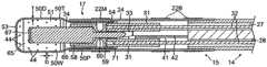
図1は、先端アブレーション電極17を通じた灌注流が改善されたカテーテル10の一実施形態を示したものである。先端電極は、流体有効範囲及び流れの均一化を先端電極外部の全ての場所にて行う際に、先端電極への流体の流れ及び先端電極内での拡散を促進するように構成される。したがって、カテーテルは、先端電極の冷却を向上すると同時に、患者に対する流体負荷を軽減しながら、より低い流量にて動作可能である。更に、先端電極における流体の流出速度が大きいことにより、先端電極の周囲に流体の境界層を形成するうえで有効な「噴射」作用が与えられ、これによりアブレーションの際の焦げ及び/又は血栓の発生率が低減される。先端電極からアブレーション部位に、例えば、生理食塩水又はヘパリン化生理食塩水などの流体が輸送されることによって、組織を冷却し、血液の凝固を低減し、かつ/又はより深い損傷部位の形成を促すことができる。神経阻害剤及び神経興奮剤などのあらゆる診断用及び治療用の流体を含む他の流体を同様に供給することも可能である点は、理解されるであろう。 FIG. 1 illustrates one embodiment of a
カテーテル10は、近位端及び遠位端を有する細長いカテーテル本体12、カテーテル本体12の遠位端の中間偏向部分14、及び灌注されたマッピング及びアブレーション先端電極17を有する遠位部分15を有する。カテーテルは更に、中間部分14の偏向方向(1方向又は2方向)を制御するための制御ハンドル16をカテーテル本体12の近位端に含む。
図2A及び図2Bを参照すると、カテーテル本体12は、1個の軸方向又は中央管腔18を有する細長い管状構造を含む。カテーテル本体12は可撓性、すなわち、折り曲げ可能であるが、その長さに沿っては実質的に非圧縮性である。カテーテル本体12は、任意の適当な構造のものであってよく、任意の適当な材料で製造することができる。現在好ましい構成体は、ポリウレタン又はPEBAXで製造された外壁20を含む。外壁20には、ステンレス鋼などの編組メッシュが埋め込まれていることによってカテーテル本体12のねじり剛性が高められているため、制御ハンドル16が回転すると、カテーテル10の中間部分14がこれに応じて回転する。 With reference to FIGS. 2A and 2B, the
カテーテル本体12の外径は重要ではないが、好ましくは約8フレンチ以下、より好ましくは7フレンチである。同様に外壁20の厚さもそれほど重要ではないが、外壁20は、中央管腔18が引っ張り部材(例えば、引っ張りワイヤ)、リード線、及び他の任意の所望のワイヤ、ケーブル又は管を収容できるように充分に薄い。必要に応じて、外壁20の内面は、ねじり安定性を向上させるために補強管22で裏打ちされる。開示した実施形態では、カテーテルは、外径約2.286mm(0.090インチ)〜約23.9mm(0.94インチ)及び内径約1.549mm(0.061インチ)〜約1.651mm(0.065インチ)の外壁20を有する。 The outer diameter of the
強化管22及び外壁20の遠位端は、ポリウレタン接着剤などによる接着接合部23を形成することによってカテーテル本体12の遠位端の近くに固定的に取り付けられている。第2の接着接合部25が、例えば、ポリウレタンなどの乾燥はより遅いがより強力な接着剤を使用して、強化管20の近位端と外壁22の近位端との間に形成される。 The distal ends of the reinforcing
制御ハンドル16と偏向可能な部分14との間に延在する要素は、カテーテル本体12の中央管腔18を通過する。これらの要素には、遠位部分15の先端電極17及びリング電極22用のリード線30、遠位部分15に流体を供給するための灌注管38、遠位部分に保持された位置特定センサ34用のケーブル33、中間部分14を偏向させるための引っ張りワイヤ32、並びに遠位側の先端部分15の温度を検知するための一対の熱電対ワイヤ41、42が含まれる。 An element extending between the control handle 16 and the
図2A、図2B及び図2Cは、管19の短い部分からなる中間部分14の一実施形態を示している。この管もやはり編組されたメッシュの構造を有しているが、例えば、管腔26、27、28及び29のような軸線から外れた複数の管腔を有している。第1の管腔26には、中間部分を偏向させるための引っ張りワイヤ32が収納されている。2方向に偏向させるために、正反対の位置にある第2の管腔27に第2の引っ張りワイヤ32を収納することができる。第3の管腔28には、リード線30、熱電対ワイヤ41及び42、並びにセンサケーブル33が収納されている。第4の管腔29には、灌注管38が収納されている。 2A, 2B and 2C show an embodiment of the
中間部分14の管19は、カテーテル本体12よりも高い可撓性を有する適当な毒性の無い材料で製造されている。管材19に適した材料は、編組ポリウレタン、すなわち、編組ステンレス鋼などのメッシュが包埋されたポリウレタンである。それぞれの管腔の大きさは重要ではないが、それを通して延在するそれぞれの構成要素を格納するのに十分である。 The
カテーテル本体12を中間部分14に取り付ける手段が、図2A及び図2Bに示されている。中間部分14の近位端は、カテーテル本体12の外壁20の内側表面を受容する外周ノッチ23を備えている。中間区域14及びカテーテル本体12は、糊等により取り付けられる。 Means for attaching the
必要に応じて、スペーサ(図示せず)を、カテーテル本体内の、補強管の遠位端(提供される場合)と中間区域の近位端との間に配置できる。スペーサは、カテーテル本体と中間区域との間の接合部で可撓性の変化をもたらし、これにより接合部が折り畳まれること又はよじれることなく滑らかに曲がることが可能になる。このようなスペーサを有するカテーテルは、米国特許第5,964,757号に開示され、この開示は参考として本明細書に組み込まれる。 If desired, a spacer (not shown) can be placed in the catheter body between the distal end of the stiffening tube (if provided) and the proximal end of the intermediate section. The spacer provides a change in flexibility at the junction between the catheter body and the intermediate section, which allows the junction to bend smoothly without being folded or kinked. A catheter having such a spacer is disclosed in US Pat. No. 5,964,757, the disclosure of which is incorporated herein by reference.
それぞれの引っ張りワイヤ32は、Teflon(登録商標)でコーティングされることが望ましい。引っ張りワイヤは、例えば、ステンレス鋼又はNitinolなどの任意の適当な金属で製造され、Teflonコーティングによって引っ張りワイヤに潤滑性を付与することができる。引っ張りワイヤは、約0.152〜約0.254mm(0.006〜約0.010インチ)の範囲の直径を有することが好ましい。 Each
図2Bに示されるように、カテーテル本体12内部の各引っ張りワイヤ32の一部は、その引っ張りワイヤを包囲する圧縮コイル35を通過する。圧縮コイル35は、カテーテル本体12の近位端から中間部分14の近位端まで延びている。圧縮コイルは、任意の適当な金属、好ましくはステンレス鋼で形成され、それ自体緊密に巻回されることによって可撓性、すなわち屈曲性を与えるが、圧縮には抗し得る。圧縮コイルの内径は、引っ張りワイヤの直径よりもわずかに大きいことが好ましい。カテーテル本体12内で、圧縮コイル35の外側表面はまた、例えば、ポリイミドのチューブ材で製造された、可撓性の非電導性シース39で被覆されている。 As shown in FIG. 2B, a portion of each
各引っ張りワイヤ32の近位端は、制御ハンドル16に係留されている。各引っ張りワイヤ32の遠位端は、下記に更に述べるように遠位部分15内に係留されている。平面に沿った中間部分14と遠位部分15の偏向をそれぞれ生じさせる、カテーテル本体12に対する引っ張りワイヤ32の個別かつ独立した長手方向の運動は、制御ハンドル16の偏向部材の適当な操作によって実現することができる。適切な偏向部材及び/又は偏向組立体が、2008年12月30日出願のDEFLECTABLE SHEATH INTRODUCERという名称の同時係属中の米国特許出願第12/346,834号、及び2008年5月27日出願のSTEERING MECHANISM FOR BI−DIRECTIONAL CATHETERという名称の米国特許出願第12/127,704号において記載されており、これらの特許の両方の開示内容の全体は、引用により本明細書に組み入れられる。 The proximal end of each
中間部分14の遠位端には遠位側の先端部分15が配置され、先端部分15は、先端電極17、及び先端電極17と中間部分14との間の比較的短い連結管部分、すなわち、被覆部材24を含む。図3及び4に示される実施形態では、連結管24は単一の管腔を有し、これに、先端電極17内へと延びる先端電極及びリング電極用のリード線30、センサケーブル33、熱電対ワイヤ41及び42、引っ張りワイヤ32、並びに灌注管38を通過させることができる。連結管24の単一の管腔により、これらの要素は、必要に応じて中間部分14内のそれぞれの管腔から先端電極17内部のそれぞれの位置に向かって再び向きを変えることができる。開示される実施形態では、管24は6mm〜12mmの範囲、より好ましくは約11mmの長さを有する、例えば、PEEK製の管のような保護管である。先端電極及びリング電極用リード線30などの選択された要素は、他の要素及び先端電極の構造を分かりやすくするために示されていない点には注意を要する。 A
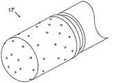
図3A及び図3Bに分かりやすく示されるように、先端電極17は長手方向軸を有し、導電性シェル50、内部部材52、並びにシェル及び内部部材によって概ね包囲かつ囲繞されている空洞又はチャンバ51を含む2つの部分からなる構成となっている。シェルは、管状又は円筒状の形状を有する細長いものである。シェルは、閉鎖して丸みを帯びた非外傷性の遠位端53と、内部部材によってシールされた開放した近位端54と、を有する。図の実施形態では、シェルは径方向に対称であり、シェル50の径方向の断面は円形であるが、径方向の断面は、任意の所望の形状であってよい点は理解されるであろう。シェルは、遠位側部分50D、近位側部分50P、及び2つの部分の間に配され、2つの部分を連結する短いテーパ部分50Tを有する。空洞51はシェルの長さにわたって延びているため、遠位側部分50Dの内側寸法、すなわち内径RD、テーパ部分50Tの内側寸法、すなわち内径RT、及び近位側部分50Pの内側寸法、すなわち内径RPがあり、各半径には以下の関係がある。すなわち、RD>RPかつRD>RT>RP。開示される実施形態では、RDは約1.15mmであり、RPは約1.0mmであり、RTは約1.075mmである。遠位端53から近位端54までのシェルの長さは約2mm〜12mm、好ましくは約3mm〜10mmの範囲であり、より好ましくは約7.5mmである。 As clearly shown in FIGS. 3A and 3B, the
シェルの近位側部分の内側の内部部材52は、シェルの長さの約半分の長さを有する。内部部材は径方向に対称であり、幅狭の軸上柄部60によって連結された遠位側部分(又はバッフル部材)58と近位側部分(又はプラグ部材)59とを有する。バッフル部材はより長く、プラグ部材はより短い。開示される実施形態では、内部部材52は径方向に対称であり、その長さは約3.0mm〜4.0mmであり、バッフル部材58の長さはプラグ部材59の長さの約2倍である。 The inner member 52 inside the proximal portion of the shell has a length that is approximately half the length of the shell. The inner member is radially symmetric and has a distal portion (or baffle member) 58 and a proximal portion (or plug member) 59 connected by a narrow
図5及び図6を参照すると、プラグ部材59はシェル50の近位側部分50Pの円形の断面に対応した円形の断面を有するため、先端電極17の近位端54において流体密シールをもたらす緊密な嵌合部を形成する。プラグ部材59はシェル50の内部空洞51をシールし、シェル及びプラグ部材は空洞の内部をプレナム状態(すなわち、下記に更に述べるように、シェルに形成された流体ポート44を通じて流体がより均一に分配されるように、流体が空洞内に圧送又は供給される場合)とすることを容易にする。 Referring to FIGS. 5 and 6, the
バッフル部材58は、バッフル部材を囲むシェルの内側の径方向断面と形状が一致しない径方向断面を有しているため、別個の間隙又は通路が形成されて先端電極を通じて流体が流れることができる。開示される実施形態では、バッフル部材58は、複数の角度をなしたバッフル、すなわちほぼ平坦な表面62を有する、例えば、図に示される三角形の断面のような多角形の断面を有する。各表面間の切り詰められた角部63は、シェル壁の内面と接触するような寸法に構成されている。内部部材52は、バッフル部材58、柄部60及びプラグ部材59を含む内部部材の長さの全体を通じて延びる軸線上の通路64を有する。バッフル部材58を通じて延びる通路の遠位側部分64Dは、位置センサ34の近位側部分を収容する。柄部60及びプラグ部材59を通じて延びる通路64の近位側(かつより狭い)部分64Pは、センサケーブル33がセンサから近位方向に延びることを可能とする。通路の遠位側部分と近位側部分との接合部は、位置センサ34の近位端に対して当接する係止部64Jとして機能する。開示される実施形態では、通路の遠位側部分64Dの長さは、位置センサ34の長さの約半分である。センサ34の遠位側部分は、ポリイミド管などの非導電性かつ生体適合性の管66によって周囲の流体からシールかつ保護されており、管66の遠位端は位置センサ34の遠位端をわずかに越えて延び、シーラント材料の栓67によってシールされている。管66の遠位端はシェル50の遠位端53よりも近位側に位置するため、流体が循環してシェルの遠位端に達することができるような空間又は間隙65が存在する。 Since the
内部部材52の柄部60は概ね円形の径方向の断面形状を有し、通路64Pの直径よりもわずかに大きい直径を有する。その直径が小さいことにより、灌注管38から流出した流体はバッフル部材58の近位面に衝突して循環し、先端電極のチャンバ51を効果的に充填した後に遠位方向に流れることになる。 The
プラグ部材59の近位端には、外周リップ70が形成されている。先端電極17が組み立てられた状態では、シェル50の近位端54がリップの遠位面に当接する。リップは、シェル50が内部部材52の周囲に不適切に配設されることを防止する。詳細には、リップによってバッフル部材の遠位端とシェルの遠位端との間の間隙65が確保される一方で、バッフル部材の切り詰められた角部によって、シェルと内部部材とが軸線上に一直線に確実に配置される。連結管24の遠位側部分は、管24の遠位端がシェルのテーパ部分50T又はその近くに位置するように、リップ70及びシェル50の近位側部分50Pを覆って延びる。 An outer
プラグ部材59の近位面には、止まり穴71、73及び74が設けられている。各引っ張りワイヤ32の遠位端は、当該技術分野で既知のフェルール31によって穴71内に係留される。先端電極用リード線30の遠位端は穴74内に係留され、熱電対ワイヤ41、42の遠位端は穴73内に係留される。上記に述べたように、軸線上の貫通通路64には、センサ34及びケーブル33が収容される。先端電極17の閉鎖チャンバ51に流体を供給する灌注管38の遠位端を受容するため、例えば、軸線から外れた貫通通路75のような別の貫通通路がプラグ部材59に設けられている。本発明の特徴の1つに従って、貫通通路75は、プラグ部材59の近位面の限られたスペースを効率的に利用する所定の断面形状を有する。すなわち、内部部材52を含む先端電極17は、下記式(1)によって定義される流体入口のアスペクト比(比入口)を考慮している。
比入口=L/W 式(1)
式中、
Lは、大きい方(長さ方向)の寸法であり、
Wは、小さい方(幅方向)の寸法である。On the proximal surface of the
Specificinlet = L / W Formula (1)
Where
L is the dimension of the larger one (length direction),
W is the dimension of the smaller one (width direction).
詳細には、プラグ部材59は、式(2)に示されるように比(比入口)が1.0以上の値に限定され、好ましくは式(2a)に示されるように10以下の値であるような灌注入口通路の径方向断面を有する。
比入口≧1
式(2)Specifically, the
Specificinlet ≧ 1
Formula (2)
図に示される実施形態では、流体入口通路75の卵形又は楕円形の断面形状は式(1)及び(2)によって定義され、上記の各寸法が互いにほぼ直交する場合を含むがこれに限定されない。図に示される実施形態は卵形又は楕円形であるが、本発明は、図7に示されるような不規則な円形、規則的又は不規則な多角形、並びに例えばインゲン豆形、三日月形、ピーナッツ形、砂時計形、及び洋なし形などの「アメーバ」状の形状を含む任意の非円形の形状を有する灌注入口を対象とすることは理解されるであろう。通路がとり得る非円形の断面形状は、互いに接触かつ/又は近接した2以上の複数の灌注管38の組み合わせによって形成されてもよい。実際、例えば、ファンネルシール又はスリーブによって通路がその近位端において効果的にシールされていさえすれば、灌注管の束を入口通路75に挿入することができる。実際、多数の異なる非円形形状は、先端電極内の他の要素の配置及び配列、入口通路を形成する際のプラグ部材の製造手段、及び/又は灌注管を入口通路に対してシールする手段によってのみ影響される。本発明は、非円形の断面形状は、円形の形状と比較して先端電極内部の空間をより効率的に利用できるという認識に基づいている。例えば、ポリイミドなどの可撓性材料で形成された灌注管は貫通通路の形状に容易に適合し得るため、管はその長さに沿って接着接合部を形成することなく連続的となり得る。図3Bに示されるように、少なくとも遠位部分15を通じて連続した灌注管38が使用されている。灌注管38の可撓性及び弾性のため、その長さに沿って異なる断面が可能である。概ね連結管24の内部に延びる管の遠位側部分38Dは、灌注貫通通路75の断面と同様の断面及びサイズを有している。連結管24の近位側の部分38Pは、より一般的な円形の断面を有している。 In the illustrated embodiment, the oval or elliptical cross-sectional shape of the
シェル50は、生体適合性合金を含む生体適合性金属で形成される。適当な生体適合性合金としては、ステンレス鋼合金、貴金属合金、及び/又はこれらの組み合わせから選択される合金が挙げられる。一実施形態では、このシェルは、約80重量%のパラジウム及び約20重量%の白金を含む合金で構築される。別の実施形態では、シェルは、約90重量%の白金及び約10重量%のイリジウムからなる合金で構築される。シェルは、取り扱い、患者の体内での輸送、並びにマッピング及びアブレーション手術の際の組織との接触に適した、充分に薄いが頑丈なシェル壁50Wを製造する深絞り製造プロセスによって形成することができる。開示される実施形態では、シェル壁50Wは、通常、約0.076mm(0.003インチ)〜0.254mm(0.010インチ)、好ましくは約0.076mm(0.003インチ)〜0.102のmm(0.004インチ)、更に好ましくは、約0.0889mm(0.0035インチ)の範囲の均一な厚さTを有する。深絞り法は充分に薄い壁を有するシェルを製造するのに非常に適しているが、ドリル穿孔及び/又はキャスティング/型成形などの他の方法を用いることもできる点は理解されるであろう。
充分に薄いシェル壁では、放電加工(EDM)法を用いることによって、チャンバ51とシェルの外部との流体連通を可能とする遠位側部分50Dのシェル壁50Wの複数の流体ポート又はオリフィス44を形成することができる。開示される実施形態では、複数のポート44は、約20個〜96個、好ましくは約30個〜60個の範囲、より好ましくは約56個である。それぞれの流体ポートの直径Dは、約0.076のmm(0.003インチ)〜0.178mm(0.007インチ)、好ましくは約0.076のmm(0.003インチ)〜0.102mm(0.004インチ)、更に好ましくは約0.0889mm(0.0035インチ)の範囲である。 For sufficiently thin shell walls, by using an electrical discharge machining (EDM) method, multiple fluid ports or
開示される実施形態では、56個のポートが6つの外周の列に配列され、5つの列R1〜R5がそれぞれ10個のポートを有し、遠位側の列R6が6個のポートを有する。列R1〜R5のポートは互いにほぼ等間隔であるが、隣り合う列のポートは互いにオフセットしているために、各ポートは4個又は6個の隣接するポートから等間隔となっている。最も遠位側の10個のポートからなる列R5は、丸みを帯びたシェルの遠位側部分に配置される。列(又は円)R6は、シェルの平坦又はほぼ平坦な遠位端53に配置されている。列R6の6個のポートは、円上で等角度に配置されている。 In the disclosed embodiment, 56 ports are arranged in 6 outer rows, 5 rows R1-R5 each have 10 ports, and distal row R6 has 6 ports. . The ports in the rows R1 to R5 are substantially equidistant from each other, but since the ports in adjacent rows are offset from each other, each port is equidistant from four or six adjacent ports. Row R5, consisting of the ten most distal ports, is located in the distal portion of the rounded shell. Row (or circle) R6 is located at the flat or nearly flat
本発明の別の特徴に従って、シェル50を含む先端電極17は、下記式(3)によって定義される流体ポートの比(比ポート)を考慮した構成を有する。
比ポート=T/D
式(3)
式中、
T=シェル壁の厚さであり、
D=流体ポートの直径である。In accordance with another feature of the present invention, the
Specificport = T / D
Formula (3)
Where
T = the thickness of the shell wall,
D = diameter of the fluid port.
詳細には、本発明の先端電極は、流体ポートのアスペクト比(比ポート)が下記式(4)に示されるように3.25未満、好ましくは式(5)に示されるように約1.5以下、より好ましくは下記式(6)に示されるように約1.0以下である。
比ポート<3.25 式(4)
比ポート≦1.5 式(5)
比ポート≦1.0 式(6)Specifically, the tip electrode of the present invention has a fluid port aspect ratio (ratioport ) of less than 3.25, as shown in equation (4) below, preferably about 1. As shown in equation (5). 5 or less, more preferably about 1.0 or less as shown in the following formula (6).
Specificport <3.25 Equation (4)
Specificport ≦ 1.5 Formula (5)
Specificport ≦ 1.0 Formula (6)
シェル壁の厚さTが流体ポートの直径Dよりも小さい場合を含め、所定の直径Dの流体ポート44を有する薄いシェルの構成は、後述するような特徴的な諸特性により機能する薄板オリフィス流として特徴付けられる、先端電極を通じた流体の流れを促進するものである。 The configuration of a thin shell having a
下記式(7)は、エネルギー保存の原理に基づいたベルヌーイの法則の一表現を示したものである(位置エネルギーが無視できるように流れの高さが共通であるという仮定を適用すると、圧力と運動エネルギーのみとなる)。
P外部=先端電極の外部の放出周囲圧、
P内部=先端電極の内部の灌注管の遠位端の上流圧、
ΔP外部−内部=流体ポートにおける圧力損失、
V外部=先端電極の外部の速度、
V内部=先端電極の内部の速度、
ρ=密度Equation (7) below shows an expression of Bernoulli's law based on the principle of energy conservation (applying the assumption that the flow height is common so that the potential energy is negligible) Only kinetic energy).
Poutside = discharge ambient pressure outside the tip electrode,
Pinside = upstream pressure at the distal end of the irrigation tube inside the tip electrode,
ΔPexternal-internal = pressure loss at fluid port,
Voutside = speed outside the tip electrode,
Vinside = speed inside tip electrode,
ρ = density
流体ポートにおける圧力損失が低いか無視できる(圧力低下は放出係数とともに含まれる)ものと仮定し、下記式(8)及び(9)に示されるように速度V外部及びV内部を流速と直径によって表すと、
D外部=流体ポートの直径Assuming that the pressure loss at the fluid port is low or negligible (the pressure drop is included with the discharge coefficient), the velocity Voutside and Vinside are dependent on the flow velocity and diameter as shown in equations (8) and (9) below. To represent
DExternal = Fluid port diameter
流体中の圧力低下は、下記式(10)によって表すことができる:
流体ポートは各流体ポート間の間隔よりも小さいため、D内部がD外部よりも大幅に大きい場合には、式(10)は下記式(11)に単純化することができる。式(11)は、流体ポートの直径が大きくなるに従って、流体力学的抵抗は4乗で減少することを示している。
ΔP=ρ(8Q2)/(π2D外部4)
式(11)Since the fluid port is smaller than the interval between each fluid port, when theinside of D is significantly larger than theoutside of D, equation (10) can be simplified to equation (11) below. Equation (11) shows that as the fluid port diameter increases, the hydrodynamic resistance decreases by the fourth power.
ΔP = ρ (8Q2 ) / (π2 Dexternal4 )
Formula (11)
本発明の別の特徴は、先端電極が下記式(12)に示されるような拡散比(比拡散)を考慮している点である。
比拡散=A出力/A入力 式(12)
式中、
A出力は、シェルのすべての流体ポートの全体の面積であり、
A入力は、灌注管の遠位端の入口の面積である。Another feature of the present invention is that the tip electrode considers a diffusion ratio (specificdiffusion ) as shown in the following formula (12).
Specificdiffusion = Aoutput / Ainput formula (12)
Where
Aoutput is the total area of all fluid ports of the shell,
The Ainput is the area of the inlet at the distal end of the irrigation tube.
詳細には、本発明の先端電極の構成によって拡散比(比拡散)が、下記式(13a)に示されるように約2.0未満、好ましくは式(13b)に示されるように約1.8未満、より好ましくは式(13c)に示されるように約1.3未満に制限される。
2.0>比拡散 式(13a)
1.8>比拡散 式(13b)
1.3>比拡散 式(13c)Specifically, the diffusion ratio (specificdiffusion ) is less than about 2.0 as shown in the following formula (13a), preferably about 1. as shown in the formula (13b) by the configuration of the tip electrode of the present invention. It is limited to less than 8, more preferably less than about 1.3 as shown in formula (13c).
2.0> Relativediffusion type (13a)
1.8> Relativediffusion formula (13b)
1.3> Relativediffusion formula (13c)
上記の式(7)のベルヌーイの法則では、流体が圧縮不能であり、管路を通じて移動する際に摩擦がないものと仮定している。現実的には、速度は、流体の粘性に応じて流体全体を通じて変化する。灌注されたカテーテルを通じた速度のように充分に小さな速度では、一般的に流れは層流、すなわち多層化している。層流では、速度は、円形の円筒状断面を有する管路にわたって放物線状に変化する。速度が臨界値を上回って増大すると、流体の速度と密度に応じて渦が発生して流れが乱流となる。 Bernoulli's law in equation (7) above assumes that the fluid is incompressible and that there is no friction when moving through the conduit. Realistically, the velocity varies throughout the fluid depending on the viscosity of the fluid. At a sufficiently small velocity, such as the velocity through an irrigated catheter, the flow is generally laminar, i.e. multilayered. In laminar flow, the velocity varies parabolically across a conduit having a circular cylindrical cross section. When the velocity increases above the critical value, vortices are generated according to the velocity and density of the fluid and the flow becomes turbulent.
管路を通じた層流は、単位時間当たりに流れる流体の体積が、管路の端部管の圧力差ΔP及び管路の半径rの4乗に比例することを述べた、下記式(14)に示されるハーゲン・ポアズイユの法則によって説明される。
Q=単位時間当たりに流れる流体の体積、
ΔP=管路の端部間の圧力差、
r=管路の半径、
L=管路の長さ、
η=与えられた流体の特性の1つである動粘度In the laminar flow through the pipe, the volume of the fluid flowing per unit time is proportional to the pressure difference ΔP of the pipe at the end of the pipe and the fourth power of the radius r of the pipe. Explained by Hagen-Poiseuille's law.
Q = volume of fluid flowing per unit time,
ΔP = pressure difference between the ends of the pipeline,
r = pipe radius,
L = the length of the pipeline,
η = kinematic viscosity, one of the properties of a given fluid
ΔPについて解くことにより、式(14)は、下記式(15)に示されるように、流速と半径の関数として圧力の変化によって表される。
したがって、半径が増大すると圧力の変化は大幅に減少し、またその逆も成り立つ。更に、流体力学的抵抗RHは、下記式(16)に示されるように速度と管路の形状の関数であることから、半径が増大すると流体力学的抵抗は大幅に減少し、またその逆も成り立つ。
本発明では、先端電極のシェルは、複数の所定の流体ポート44を有する薄い先端電極のシェル壁50Wを用いることによって、圧力の変化と流体ポートの半径との間、及び流体力学的抵抗と流体ポートの半径との間の逆の依存関係を効果的に利用している。シェル壁の比較的小さな厚さT(式(16)では「長さL」として表される)のため、流体ポートは、流体ポート比が上記式(4)に示されるように3.25未満、好ましくは式(5)に示されるように約1.5未満、より好ましくは式(6)に示されるように約1.0未満となるように様々なサイズ及び半径(式(16)では「半径r」として表される)で容易に製造することが可能である。流体ポート比が近づくか、又は1.0未満になると、ポートを通る流体の流れを「薄板オリフィス流」と特徴付けることができる。更に、所定の半径又は直径の所定の複数の流体ポートで、全出力面積(例えば、先端電極シェル内のポートの数xそれぞれのポートの領域)と入力面積(例えば、入口75の横断面積)の拡散比を容易に判断して、式(13a)に関して2.0未満、好ましくは、式(13b)に関して1.8未満、更に好ましくは、式(13c)に関して約1.3未満に制限することができる。拡散比を小さくすると、灌注流体の流れは、先端電極内部の流体の背圧によっておおよそ決まることになる。更に、先端電極の内部及び外部の流体の全質量流速は、上記式(7)に示されるように保存されるはずであるから、全出力面積の減少は、先端電極で「噴射作用」を生じる流体ポートにおける、より大きな流体速度によって有利に補償される。 In the present invention, the tip electrode shell employs a thin tip
本発明の更に別の特徴に従って、先端電極17、特にシェル50及びチャンバ51は内部の断面が変化し、遠位側部分50Dで遠位側の内側の径方向寸法又は断面積がより大きく、近位側部分50Pで近位側の内側の径方向寸法又は断面積がより小さくなっており、その間で変化する内側の径方向寸法の移行をテーパ部分50Tが促している。テーパ部分は、図に示されるようにシェルの長さに沿った中間点又はその近くに位置しているが、遠位端又は近位端のいずれかにより近くともよい。シェルの長さに沿った外側の径方向寸法は変化してもしなくともよいが、電極の長さに沿って変化する内側の径方向寸法こそが、流体の流れに有利な影響を及ぼし、チャンバ内部に望ましい乱流を形成することによってプレナム状態を生じさせる。 In accordance with yet another feature of the present invention, the
式(7)に従えば、チャンバ体積が近位側部分50Pのボトルネック形成部から遠位側部分50Dにかけて拡大して拡張又は増大すると、先端電極内を遠位方向に流れる流体の圧力が増大し、速度が低下する。これにより、流体の運動量、特に運動量の軸方向成分が拡散するプレナムチャンバ効果が生じる。運動量又は灌注流体が拡散すると、先端電極の流体ポート44を通じた流体の質量流速の軸方向の変動が小さくなる。この現象の全体的な効果は、ポート44を介して先端電極のチャンバ全体にわたり、したがって先端電極の外面のすべての点における、より均一な灌注流体による被覆及び流れである。 According to equation (7), as the chamber volume expands and expands or increases from the bottleneck formation of the
当業者であれば理解されるように、先端電極は、灌注流体の流れの軸方向の変動を制御する内部形状を与える。しかしながら、本発明には、図8に示されるように、先端電極17’の長さに沿った流体ポート44の密度(シェル壁又は表面の単位面積当たりの複数のポートを含む)が変化するような代替的な実施形態も含まれる。更に、図9に示されるような別の代替的な実施形態によれば、ポートの直径が、遠位端に向かって減少する場合のように先端電極50”の軸方向の長さに沿って変化するシェルが与えられる。いずれの場合も、有効流体出力面積が先端電極の長さとともに変化し、圧力低下が補償されることによって、より均一な質量流速が与えられる。 As will be appreciated by those skilled in the art, the tip electrode provides an internal shape that controls the axial variation of irrigation fluid flow. However, the present invention allows the density of fluid ports 44 (including multiple ports per unit area of the shell wall or surface) to vary along the length of the tip electrode 17 'as shown in FIG. Alternative embodiments are also included. Further, according to another alternative embodiment, as shown in FIG. 9, along the axial length of the
連結管24に取り付けられるリング電極21は、白金又は金、好ましくは白金とイリジウムの組み合わせなどの任意の適当な固体導電性材料で製造することができる。リング電極は、接着剤などによって連結管24上に取り付けることができる。また、リング電極は、管24を白金、金及び/又はイリジウムなどの導電性材料でコーティングすることによって形成することもできる。コーティングは、スパッタリング、イオンビーム蒸着又は等価技術を用いて適用できる。管24上のリング電極の数は、必要に応じて変えることができる。各リングは、単極であっても二極であってもよい。図の実施形態では、遠位側の単極リング電極及び近位側の一対の二極リング電極を示す。各リング電極は、それぞれのリード線30Rに接続されている。 The ring electrode 21 attached to the connecting
各リードワイヤ30Rは、任意の好適な方法により、対応するリング電極に取り付けられる。リード線をリング電極に取り付けるための好ましい一方法では、最初に管24の壁を通じて小さな穴を開けることが含まれる。このような穴は、例えば、非導電性カバーを通して針を挿入し、十分に針を加熱して永続的穴を形成することにより、作製できる。リード線は、次いで、マイクロフック等を用いることにより、穴を通して引かれる。次いでリードワイヤの端部がコーティングを剥ぎ取られ、リング電極の下側に溶接され、次いでその電極が、ホールの上の所定位置に滑り込まされ、ポリウレタン系接着剤などで適所に固定される。また、各リング電極は、リード線30Rを非導電性の管24の周囲に何度も巻き、外側に面した表面のリード線自体の絶縁コーティングを剥離することによっても形成される。 Each lead wire 30R is attached to the corresponding ring electrode by any suitable method. One preferred method for attaching the lead wire to the ring electrode involves first drilling a small hole through the wall of the
先端電極17は、リード線30Tによってアブレーションエネルギー源に電気的に接続される。各リング電極21は、それぞれのリード線30Rによって適当なマッピング又は監視システムに電気的に接続される。 The
リード線30T及び30Rは、偏向可能な中間部分14の管19の管腔28及びカテーテル本体12の中央管腔18を通過する。カテーテル本体12の中央管腔18及び管腔28の近位端を通じて延びる各リード線の部分は、任意の適当な材料、好ましくはポリイミドで形成することができる保護シース(図示せず)の内部に収納することができる。保護シースの遠位端は、ポリウレタン接着剤などにより管腔28内に接着することによって中間部分14の近位端に係留される。各電極のリードワイヤは、制御ハンドル16の近位端部にてコネクタ内で終端する近位端部を有する。 Leads 30T and 30R pass through
本発明の先端電極は、30ワット未満では約8mL/min以下、30〜50ワットでは約17mLで動作し得る。したがって、5〜6時間の手術では、患者に対する流体負荷の軽減が極めて顕著となり得る。更に、プログラム可能なポンプによって流速が調節される場合には、低いワット数での流速が更に低くなり得る。 The tip electrode of the present invention can operate at about 8 mL / min or less for less than 30 watts and about 17 mL for 30-50 watts. Therefore, in 5-6 hours of surgery, the reduction in fluid load on the patient can be very significant. Furthermore, if the flow rate is adjusted by a programmable pump, the flow rate at lower wattage can be even lower.
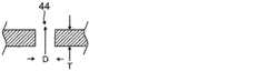
図10を参照すると、直角の円柱形の構成による流体ポート44が示されており、直径Dは、約0.076〜0.127mm(0.003〜0.005インチ)の範囲であり、シェル厚さTは、約0.076〜0.102mm(0.003〜0.004インチ)の範囲である。流体ポートは、形彫りEDM技術で製造される。タングステン電極が、電気侵蝕により個々の灌注ポートを形成するためにシェル壁に漸進的に突っ込まれる。まっすぐな円形の電極で、直角の円柱形の灌注ポートにはまっすぐな平行した壁が形成される。このプロセスは、所望の複数のポートを形成するためにシェル上で複数回繰り返される。 Referring to FIG. 10, there is shown a
図11を参照すると、テーパ付き円柱形の、又は円錐台形の構成による流体ポート44’であり、テーパ部αの角度は、約0〜10°、好ましくは約4〜6°の範囲である。一実施形態では、内側/入口ポート直径D1は、約0.076mm(0.003インチ)〜0.102mm(0.004インチ)の範囲であり、外側/出口ポート直径D2は、約0.102〜0.127mm(約0.004〜0.005インチ)の範囲であり、シェル厚さTは、約0.076〜0.102mm(約0.003インチ〜0.004インチ)の範囲である。本発明の特徴に従って、テーパ角αは、以下で説明するように、灌注ポートの流れに有益な影響を与える。 Referring to FIG. 11, a
図11を参照すると、以下のパラメータでの検討を行ったところ、灌注ポートの流れに及ぼすテーパ角の影響が実証された。
ポート直径D:0.076mm(0.003インチ)〜0.127mm(0.005インチ)
シェル厚さT:0.076mm(0.003インチ)〜0.102mm(0.004インチ)
バルク体積流量(bulk volumetric flow rate)F:8mL/min〜15mL/min
テーパ角α:0〜6°Referring to FIG. 11, examination of the following parameters demonstrated the effect of taper angle on irrigation port flow.
Port diameter D: 0.076 mm (0.003 inch) to 0.127 mm (0.005 inch)
Shell thickness T: 0.076 mm (0.003 inch) to 0.102 mm (0.004 inch)
Bulk volumetric flow rate F: 8 mL / min to 15 mL / min
Taper angle α: 0 to 6 °
流体ポート44を通る塩の流れを、ベルヌーイの式の適用により理論的にモデル化することができる。定常的な非圧縮性流れ及び無視できる摩擦損失という仮定で、ベルヌーイの式は、以下になる。
一般に、全体にわたってCdを除いた変数が、まっすぐでテーパ付きノズルの間で一定であると仮定した場合、ベルヌーイの式は、以下とすることができる。
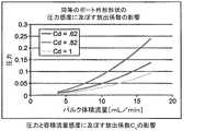
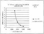
理論的なモデル化の代替手法は、コンピュータの数値解析法を使用することである。数値流体力学(CFD)分析は、異なる直径、テーパ角、及び体積流量にわたって単一の流体ポートを通る流体の流れ上で行われた。図14、15及び16に示すような実験的な空間を効率的に調べるために、複数のCFD実行の結果が、応答曲面DOEモデルにおいてMinitab内に読み込まれた。中央の合成DOEデザインを利用してCFD実行の組み合わせを生成した。最終応答プロットを直線近似を使用して生成した。これらのプロットでは、8mL/min及び15mL/minの両方の体積流量には、テーパ角の効果は、12°でさえ最小である。図16において生成される多変量線形関数を使用して、まっすぐな流体ポート44(図10)及びテーパ付き流体ポート44’(図11)の圧力降下を5%未満の差にて予想することができる。 An alternative to theoretical modeling is to use computer numerical analysis. Computational fluid dynamics (CFD) analysis was performed on the fluid flow through a single fluid port over different diameters, taper angles, and volumetric flow rates. In order to efficiently examine the experimental space as shown in FIGS. 14, 15 and 16, the results of multiple CFD runs were read into Minitab in a response surface DOE model. A central synthetic DOE design was used to generate CFD execution combinations. The final response plot was generated using a linear approximation. In these plots, for both 8 mL / min and 15 mL / min volume flow, the effect of the taper angle is minimal even at 12 °. Using the multivariate linear function generated in FIG. 16, the pressure drop across the straight fluid port 44 (FIG. 10) and the tapered
更に、図16の回帰表は、テーパ角について0.938のP値を示しており、これは統計的有意性はほとんどなく、したがって、流量及び入口ポート直径に対する軸方向の圧力降下に及ぼす影響が最小であることを示す。 In addition, the regression table of FIG. 16 shows a P value of 0.938 for the taper angle, which has little statistical significance, and therefore the effect on axial pressure drop on flow rate and inlet port diameter. Indicates minimum.
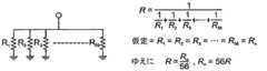
先に論じたように、先端電極シェルの壁の厚さ、その結果、流体ポート導管の「長さ」が、ポートを通る流れに影響を与える。Cdを正確には予測することができないために、代替手法は、ポートの全耐水圧性RHを特徴づけることであろう。耐水圧性により、流体の単位体積をポートに通すために必要とされる力の分配量が、実際上定量化されることになる。流体ポートについてRHを特徴づけるために、電気回路をアナログとみなすことが便利である。図17に示すように灌注先端シェルを通るバルク流体の流れに類似の単一の抵抗器回路を構築することができる。 As discussed above, the wall thickness of the tip electrode shell and, consequently, the “length” of the fluid port conduit affects the flow through the port. Since Cd cannot be predicted accurately, an alternative approach would be to characterize the total hydraulic resistance RH of the port. The water pressure resistance effectively quantifies the amount of force distribution required to pass a unit volume of fluid through the port. In order to characterize the RH for the fluid port, it is convenient to consider the electrical circuit as analog. A single resistor circuit similar to bulk fluid flow through the irrigation tip shell can be constructed as shown in FIG.
オームの法則を使用して、以下のように、図17の電気回路抵抗を電圧V及び電流iの関数として表することができる。
同様に、上記の水圧「回路」の抵抗RHは、圧力水頭P及び体積流量
式(20)は、共に灌注アブレーション先端電極の56の流体ポートの抵抗に対応する。しかしながら、全てのポートはほぼ同じサイズ、したがって同じ抵抗であると仮定して、それぞれのポートの個々の抵抗を図18に示すように、並列抵抗ネットワークアナログを使用して導出することができる。個々の抵抗器の電気抵抗は以下として表すことができる。
同じ引数により、水圧アナログを同様に以下として表すことができる。
上記の関係を用いて、先端電極の入口での圧力水頭P及び結果のバルク体積流量を測定することにより、所与のポート外形形状の耐水圧性を定量的に特徴づけることができる。
図19を参照すると、流れ固定具500は、様々な灌注先端シェルについて耐水圧性RHnを定量的に測定するために開発されたものである。流れ固定具500は、熱電対501、圧力水頭部502(貯水槽503、圧力計(基準確認)504及び先端シェル505を含む)、及び回収ビーカー506を含む。先端シェル505内の圧力Pは、ヘッド高さを介して正確に制御される。圧力は、以下の方程式を介してヘッド高さに関係づけられる。
体積流量
その後、個々のポートの耐水圧性RHnを以下として計算することができる。
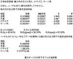
まず、様々なポート構成の先端シェルを走査型電子顕微鏡(SEM)で寸法的に特徴づけた。結果は、図20に要約されている。寸法的な特徴づけの後、それぞれの試料を流れ固定具500で試験した。体積流量を、図21に示すようにそれぞれの圧力水頭レベル設定について記録した。図21の線形回帰から、それぞれの先端シェルのバルク耐水圧性RHを計算することができる。したがって、それぞれのポートの耐水圧性RHnは、図22に示すように、56RHに等しい。First, the tip shells of various port configurations were dimensionally characterized with a scanning electron microscope (SEM). The results are summarized in FIG. After dimensional characterization, each sample was tested with
テーパ角の影響を理解するために、図23に示すように、レーザードリル穿孔したポート外形形状試料をEDM名目生成ポート外形形状試料に相関づける。相関プロットは、同じ圧力水頭については、レーザードリル穿孔したポート外形形状試料の方が若干低い体積流量を有し、したがって、抵抗が大きいことを示す。しかしながら、EDMポート及びレーザードリル穿孔したポートの領域は異なり、レーザードリル穿孔したポートの方が、より小さく、より制限的な領域を有する。 In order to understand the influence of the taper angle, as shown in FIG. 23, the laser drilled port profile sample is correlated with the EDM nominal generation port profile sample. The correlation plot shows that for the same pressure head, the laser drilled port profile sample has a slightly lower volumetric flow rate and therefore a higher resistance. However, the area of the EDM port and the laser drilled port is different, and the laser drilled port is smaller and has a more restrictive area.
EDM試料とレーザー試料との間でデータを名目0.0889mm(0.0035インチ)の入口ポート直径(したがって、全面積)に正規化し、それによってポート抵抗に及ぼす表面積の影響を排除することにより、図24に示すように、6°のテーパ角のために耐水圧性成分が露わになる。図24のプロットでは、相関ラインの勾配は1.0198であり、これは、レーザードリル穿孔したポートには、同じ圧力水頭にてポート直径を有するEDM先端と比較すると体積流量の増大があることを示す。6°のテーパ角の影響は、1.0198の勾配と1.0の理想的な相関との間の相違である。
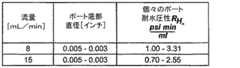
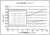
試験されたThermoCool SF灌注式先端シェルM−5787−03上の単一の灌注EDMの耐水圧性の範囲を図25の表に示す。図26を参照して、指数関数あてはめを利用して、それぞれ、0.076mm(0.003インチ)、0.0889mm(0.0035インチ)、及び0.127mm(0.005インチ)の直径のポートの明示的に試験されたEDM構成に基づいて0.102mm(0.004インチ)の直径ポートでのEDM先端の耐水圧性を補間した。補間方程式を利用して[具体的には、plsリスト式(#)(pls list Eqn(#))]、0.102mm(0.004インチ)EDM及びレーザードリル穿孔したポートの圧力と流れの関係を、図27及び図28に示すように、妥当性が確認された範囲に対して示すことができる。レーザードリル穿孔法の6°のテーパ角に対応するために圧力:流れ感度を2%を低減することにより、提案するレーザーポートの上側規格限界USLを妥当性が確認された範囲に対して示すこともできる。これらのグラフ図に基づいて、6°のテーパ角及び同等の入口ポート直径を有するレーザードリル穿孔した先端シェルは、当初のまっすぐなポートEDMカテーテルについて妥当性が確認された耐水圧性エンベロープで性能を発揮する。 The range of hydraulic resistance of a single irrigated EDM on the ThermoCool SF irrigated tip shell M-5787-03 tested is shown in the table of FIG. Referring to FIG. 26, using exponential fitting, the diameters of 0.076 mm (0.003 inch), 0.0889 mm (0.0035 inch), and 0.127 mm (0.005 inch) respectively. The hydraulic resistance of the EDM tip at a 0.102 mm (0.004 inch) diameter port was interpolated based on the explicitly tested EDM configuration of the port. Using interpolation equation [specifically, pls list equation (#) (pls list Eqn (#))], 0.102 mm (0.004 inch) EDM and laser drilled port pressure and flow relationship As shown in FIG. 27 and FIG. 28, it can be shown with respect to the range whose validity has been confirmed. Show the upper specification limit USL of the proposed laser port against a validated range by reducing pressure: flow sensitivity by 2% to accommodate the 6 ° taper angle of laser drilling. You can also. Based on these graphs, the laser-drilled tip shell with a 6 ° taper angle and equivalent inlet port diameter performs well with a water resistant envelope validated for the original straight port EDM catheter. To do.
本発明には、上記の比のいずれか又はすべてを満たすあらゆる灌注式アブレーション先端電極が含まれることは理解されるであろう。すなわち、灌注式先端電極は、二部分からなる構成を有するか否かによらず、関係する寸法及びパラメータが、上記の比のいずれか又はすべてを先端電極が満たすようなものである場合に本発明の有利な特徴をもたらすものである。先行技術は、本発明の特定の代表的な実施形態を参照して提示されてきた。当業者は、記載した構造の代替及び変化が、本発明の原理、趣旨及び範囲を逸脱することなく実施できることを理解するだろう。図面は、必ずしも縮尺通りではないことが理解される。したがって、前述の記載は、添付図面に記載及び例示された正確な構造のみに関するものとして読むべきではない。むしろ、その最も完全かつ最も正確な範囲を有する以下の特許請求の範囲に一致し、それを支持するものとして読むべきである。 It will be understood that the present invention includes any irrigated ablation tip electrode that meets any or all of the above ratios. That is, the irrigated tip electrode has a two-part configuration and is relevant when the relevant dimensions and parameters are such that the tip electrode meets any or all of the above ratios. It provides the advantageous features of the invention. The prior art has been presented with reference to certain exemplary embodiments of the invention. Those skilled in the art will appreciate that substitutions and variations of the described structures can be made without departing from the principles, spirit and scope of the invention. It will be understood that the drawings are not necessarily to scale. Therefore, the foregoing description should not be read as referring only to the precise structure described and illustrated in the accompanying drawings. Rather, it should be read as consistent with and supporting the following claims, whose fullest and most accurate scope.
〔実施の態様〕
(1) 細長いカテーテル本体と、
前記カテーテル本体の遠位側の偏向可能な部分と、
前記偏向可能な部分の遠位側の先端電極と、
それぞれ前記先端電極の全流体出力面積に寄与する所定の複数の流体ポートを有する、空洞を画定する外側シェルと、
流体入力面積を有する前記先端電極への流体入口を含む内部部材と、を備え、
それぞれの流体ポートは、テーパ状である、灌注式アブレーションカテーテル。
(2) それぞれの流体ポートが、約0.076mm(0.003インチ)〜0.127mm(0.005インチ)の入口直径を有する、実施態様1に記載のカテーテル。
(3) それぞれの流体ポートが、約0.076mm(0.003インチ)〜0.102mm(0.004インチ)の入口直径を有する、実施態様1に記載のカテーテル。
(4) それぞれの流体ポートが、約0〜6°の角度でテーパ状である、実施態様1に記載のカテーテル。
(5) 前記シェルが、約0.076mm(0.003インチ)〜0.102mm(0.004インチ)のシェル壁の厚さを有する、実施態様1に記載のカテーテル。Embodiment
(1) an elongated catheter body;
A distal deflectable portion of the catheter body;
A tip electrode distal to the deflectable portion;
An outer shell defining a cavity, each having a predetermined plurality of fluid ports that contribute to the total fluid output area of the tip electrode;
An internal member including a fluid inlet to the tip electrode having a fluid input area,
Each fluid port is tapered, an irrigated ablation catheter.
(2) The catheter of
3. The catheter of
(4) The catheter of
5. The catheter of
(6) 前記所定の複数のポートは、約56個である、実施態様1に記載のカテーテル。
(7) 細長いカテーテル本体と、
前記カテーテル本体の遠位側の偏向可能な部分と、
前記偏向可能な部分の遠位側の先端電極であって、それぞれ前記先端電極の全流体出力面積に寄与する所定の複数の流体ポートを有し、流体入力面積を有する流体入口も有する、先端電極と、を備え、
前記先端電極が、約1.8未満の拡散比を有し、それぞれの流体ポートが、テーパ付き構成を有する、灌注式アブレーションカテーテル。
(8) 前記テーパ付き構成が、円錐台形構成を含む、実施態様7に記載の灌注式アブレーションカテーテル。
(9) 前記テーパ付き構成が、約0〜6°のテーパ角を有する、実施態様7に記載の灌注式アブレーションカテーテル。
(10) それぞれの流体ポートが、約0.076mm(0.003インチ)〜0.127mm(0.005インチ)の範囲の入口直径を有する、実施態様7に記載の灌注式アブレーションカテーテル。(6) The catheter according to
(7) an elongated catheter body;
A distal deflectable portion of the catheter body;
A tip electrode distal to the deflectable portion, the tip electrode having a predetermined plurality of fluid ports each contributing to the total fluid output area of the tip electrode and also having a fluid inlet having a fluid input area And comprising
An irrigated ablation catheter wherein the tip electrode has a diffusion ratio of less than about 1.8 and each fluid port has a tapered configuration.
8. The irrigated ablation catheter of
9. The irrigated ablation catheter of
10. An irrigated ablation catheter according to
(11) 前記先端電極が、約0.076mm(0.003インチ)〜0.102mm(0.004インチ)の範囲のシェル厚さを有する、実施態様7に記載の灌注式アブレーションカテーテル。
(12) 細長いカテーテル本体と、
前記カテーテル本体の遠位側の偏向可能な部分と、
前記偏向可能な部分の遠位側の先端電極と、
それぞれ前記先端電極の全流体出力面積に寄与する所定の複数の流体ポートを有する、空洞を画定する外側シェルと、
流体入力面積を有する前記先端電極への流体入口を含む内部部材と、を備え、
前記先端電極が、所定の拡散比、所定の流体ポート比、及び所定の入口アスペクト比、並びに可変内側断面を有するチャンバを有し、
前記空洞が、前記先端電極の長さに沿って変化する内側断面を有し、
それぞれの流体ポートが、テーパ付き構成を有する、灌注式アブレーションカテーテル。11. The irrigated ablation catheter of
(12) an elongated catheter body;
A distal deflectable portion of the catheter body;
A tip electrode distal to the deflectable portion;
An outer shell defining a cavity, each having a predetermined plurality of fluid ports that contribute to the total fluid output area of the tip electrode;
An internal member including a fluid inlet to the tip electrode having a fluid input area,
The tip electrode has a chamber having a predetermined diffusion ratio, a predetermined fluid port ratio, a predetermined inlet aspect ratio, and a variable inner cross section;
The cavity has an inner cross-section that varies along the length of the tip electrode;
An irrigated ablation catheter, each fluid port having a tapered configuration.
Claims (10)
Translated fromJapanese前記カテーテル本体の遠位側の偏向可能な部分と、
前記偏向可能な部分の遠位側の先端電極と、
それぞれ前記先端電極の全流体出力面積に寄与する所定の複数の流体ポートを有する、空洞を画定する外側シェルと、
流体入力面積を有する前記先端電極への流体入口を含む内部部材と、を備え、
それぞれの流体ポートは、テーパ状であり、
それぞれの流体ポートが、入口側の開口の直径よりも出口側の開口の直径が大きくなり、4°〜6°の角度でテーパ状である、灌注式アブレーションカテーテル。An elongated catheter body;
A distal deflectable portion of the catheter body;
A tip electrode distal to the deflectable portion;
An outer shell defining a cavity, each having a predetermined plurality of fluid ports that contribute to the total fluid output area of the tip electrode;
An internal member including a fluid inlet to the tip electrode having a fluid input area,
Each fluid port is tapered,
An irrigated ablation catheter, wherein each fluid port has a larger diameter at the outlet side than the diameter of the inlet side opening and tapers at an angle of 4 ° to 6 °.
前記カテーテル本体の遠位側の偏向可能な部分と、
前記偏向可能な部分の遠位側の先端電極であって、それぞれ前記先端電極の全流体出力面積に寄与する所定の複数の流体ポートを有し、流体入力面積を有する流体入口も有する、先端電極と、を備え、
前記先端電極が、1.8未満の拡散比を有し、それぞれの流体ポートが、テーパ付き構成を有し、
前記拡散比は、以下の式で示されるものであり、
拡散比=A出力/A入力
式中、
A出力は、シェルのすべての流体ポートの全体の面積であり、
A入力は、灌注管の遠位端の入口の面積であり、
前記テーパ付き構成が、入口側の開口の直径よりも出口側の開口の直径が大きくなり、4°〜6°のテーパ角を有する、灌注式アブレーションカテーテル。An elongated catheter body;
A distal deflectable portion of the catheter body;
A tip electrode distal to the deflectable portion, the tip electrode having a predetermined plurality of fluid ports each contributing to the total fluid output area of the tip electrode and also having a fluid inlet having a fluid input area And comprising
The tip electrode has a diffusion ratio of less than 1.8 and each fluid port has a tapered configuration;
The diffusion ratio is represented by the following equation:
Diffusion ratio = Aoutput / Ainput
Where
Aoutput is the total area of all fluid ports of the shell,
Ainput is the area of the inlet at the distal end of the irrigation tube,
An irrigated ablation catheter in which the tapered configuration has a diameter of the outlet side opening larger than the diameter of the inlet side opening and has a taper angle of 4 ° to 6 °.
前記カテーテル本体の遠位側の偏向可能な部分と、
前記偏向可能な部分の遠位側の先端電極と、
それぞれ前記先端電極の全流体出力面積に寄与する所定の複数の流体ポートを有する、空洞を画定する外側シェルと、
流体入力面積を有する前記先端電極への流体入口を含む内部部材と、を備え、
前記先端電極が、所定の拡散比、所定の流体ポート比、及び所定の入口アスペクト比、並びに可変内側断面を有するチャンバを有し、
前記拡散比は、以下の式で示されるものであり、
拡散比=A出力/A入力
式中、
A出力は、シェルのすべての流体ポートの全体の面積であり、
A入力は、灌注管の遠位端の入口の面積であり、
前記流体ポート比は、以下の式で示されるものであり、
流体ポート比=T/D
式中、
T=シェル壁の厚さであり、
D=流体ポートの直径であり、
前記入口アスペクト比は、以下の式で示されるものであり、
入口アスペクト比=L/W
式中、
Lは、長さ方向の寸法であり、
Wは、幅方向の寸法であり、
前記空洞が、前記先端電極の長さに沿って変化する内側断面を有し、
それぞれの流体ポートが、テーパ付き構成を有し、
前記テーパ付き構成が、入口側の開口の直径よりも出口側の開口の直径が大きくなり、4°〜6°のテーパ角を有する、灌注式アブレーションカテーテル。An elongated catheter body;
A distal deflectable portion of the catheter body;
A tip electrode distal to the deflectable portion;
An outer shell defining a cavity, each having a predetermined plurality of fluid ports that contribute to the total fluid output area of the tip electrode;
An internal member including a fluid inlet to the tip electrode having a fluid input area,
The tip electrode has a chamber having a predetermined diffusion ratio, a predetermined fluid port ratio, a predetermined inlet aspect ratio, and a variable inner cross section;
The diffusion ratio is represented by the following equation:
Diffusion ratio = Aoutput / Ainput
Where
Aoutput is the total area of all fluid ports of the shell,
Ainput is the area of the inlet at the distal end of the irrigation tube,
The fluid port ratio is represented by the following equation:
Fluid port ratio = T / D
Where
T = the thickness of the shell wall,
D = diameter of fluid port,
The entrance aspect ratio is represented by the following equation :
Entrance aspect ratio = L / W
Where
L is the dimension in the length direction,
W is the dimension in the width direction,
The cavity has an inner cross-section that varies along the length of the tip electrode;
Each fluid port has a tapered configuration;
An irrigated ablation catheter in which the tapered configuration has a diameter of the outlet side opening larger than the diameter of the inlet side opening and has a taper angle of 4 ° to 6 °.
Applications Claiming Priority (2)
| Application Number | Priority Date | Filing Date | Title |
|---|---|---|---|
| US13/789,574 | 2013-03-07 | ||
| US13/789,574US9510894B2 (en) | 2010-04-28 | 2013-03-07 | Irrigated ablation catheter having irrigation ports with reduced hydraulic resistance |
Publications (2)
| Publication Number | Publication Date |
|---|---|
| JP2014171885A JP2014171885A (en) | 2014-09-22 |
| JP6440949B2true JP6440949B2 (en) | 2018-12-19 |
Family
ID=50239431
Family Applications (1)
| Application Number | Title | Priority Date | Filing Date |
|---|---|---|---|
| JP2014043592AActiveJP6440949B2 (en) | 2013-03-07 | 2014-03-06 | Irrigation ablation catheter having an irrigation port with reduced fluid resistance |
Country Status (8)
| Country | Link |
|---|---|
| EP (1) | EP2774567B1 (en) |
| JP (1) | JP6440949B2 (en) |
| CN (1) | CN104042328B (en) |
| AU (1) | AU2014200882B2 (en) |
| CA (1) | CA2843924A1 (en) |
| IL (1) | IL230845A (en) |
| IN (1) | IN2014DE00392A (en) |
| RU (1) | RU2666115C2 (en) |
Families Citing this family (9)
| Publication number | Priority date | Publication date | Assignee | Title |
|---|---|---|---|---|
| US11628009B2 (en)* | 2014-12-17 | 2023-04-18 | Biosense Webster (Israel) Ltd. | EP catheter with trained support member, and related methods |
| US11026745B2 (en)* | 2016-12-19 | 2021-06-08 | Boston Scientific Scimed Inc | Open-irrigated ablation catheter with proximal insert cooling |
| KR102584105B1 (en)* | 2017-01-17 | 2023-10-05 | 콜피고, 인코포레이티드. | Apparatus for ablation of tissue surfaces, and related systems and methods |
| CN108784896B (en)* | 2017-10-31 | 2024-04-05 | 杭州诺生医疗科技有限公司 | Interatrial ostomy device, interatrial ostomy system and method of operating the same |
| EP3735996B1 (en)* | 2019-05-07 | 2023-09-27 | Free Life Medical GmbH | Bi-directional perfusion cannula |
| PL3788974T3 (en) | 2019-09-05 | 2025-02-10 | Erbe Elektromedizin Gmbh | ABLATION PROBE |
| CN112603524B (en)* | 2020-11-30 | 2023-02-24 | 杭州诺生医疗科技有限公司 | Interatrial septum tissue stoma device and interatrial septum group weaving mouth system |
| CN112603617B (en)* | 2020-12-17 | 2024-03-22 | 杭州诺生医疗科技有限公司 | Atrial shunt instrument |
| CN115363740B (en)* | 2021-12-31 | 2025-04-25 | 杭州德晋医疗科技有限公司 | Ablation needle, ablation device and ablation system for myocardial ablation |
Family Cites Families (12)
| Publication number | Priority date | Publication date | Assignee | Title |
|---|---|---|---|---|
| US6129698A (en)* | 1996-05-24 | 2000-10-10 | Beck; Robert C | Catheter |
| US5964757A (en) | 1997-09-05 | 1999-10-12 | Cordis Webster, Inc. | Steerable direct myocardial revascularization catheter |
| US20030009094A1 (en)* | 2000-11-15 | 2003-01-09 | Segner Garland L. | Electrophysiology catheter |
| US6969373B2 (en)* | 2001-04-13 | 2005-11-29 | Tricardia, Llc | Syringe system |
| US8986298B2 (en)* | 2006-11-17 | 2015-03-24 | Biosense Webster, Inc. | Catheter with omni-directional optical tip having isolated optical paths |
| US7824406B2 (en)* | 2006-12-28 | 2010-11-02 | St. Jude Medical, Atrial Fibrillation Division, Inc. | Irrigated ablation catheter having a valve to prevent backflow |
| US7976537B2 (en)* | 2007-06-28 | 2011-07-12 | Biosense Webster, Inc. | Optical pyrometric catheter for tissue temperature monitoring during cardiac ablation |
| US8123745B2 (en)* | 2007-06-29 | 2012-02-28 | Biosense Webster, Inc. | Ablation catheter with optically transparent, electrically conductive tip |
| US8500730B2 (en)* | 2007-11-16 | 2013-08-06 | Biosense Webster, Inc. | Catheter with omni-directional optical tip having isolated optical paths |
| US8469919B2 (en)* | 2008-02-19 | 2013-06-25 | Boston Scientific Scimed, Inc. | Apparatus and methods for uniformly distributing coolant within a cryo-ablation device |
| US9943363B2 (en)* | 2010-04-28 | 2018-04-17 | Biosense Webster, Inc. | Irrigated ablation catheter with improved fluid flow |
| US9943362B2 (en)* | 2010-04-28 | 2018-04-17 | Biosense Webster, Inc. | Irrigated ablation catheter with improved fluid flow |
- 2014
- 2014-02-06ILIL230845Apatent/IL230845A/enactiveIP Right Grant
- 2014-02-12ININ392DE2014patent/IN2014DE00392A/enunknown
- 2014-02-20AUAU2014200882Apatent/AU2014200882B2/ennot_activeCeased
- 2014-02-26CACA2843924Apatent/CA2843924A1/ennot_activeAbandoned
- 2014-03-06JPJP2014043592Apatent/JP6440949B2/enactiveActive
- 2014-03-06RURU2014108748Apatent/RU2666115C2/ennot_activeIP Right Cessation
- 2014-03-07EPEP14158294.0Apatent/EP2774567B1/enactiveActive
- 2014-03-07CNCN201410081748.9Apatent/CN104042328B/enactiveActive
Also Published As
| Publication number | Publication date |
|---|---|
| IN2014DE00392A (en) | 2015-06-12 |
| EP2774567B1 (en) | 2017-04-19 |
| AU2014200882A1 (en) | 2014-09-25 |
| CA2843924A1 (en) | 2014-09-07 |
| RU2014108748A (en) | 2015-09-20 |
| CN104042328B (en) | 2018-12-14 |
| RU2666115C2 (en) | 2018-09-05 |
| EP2774567A1 (en) | 2014-09-10 |
| IL230845A0 (en) | 2014-09-30 |
| JP2014171885A (en) | 2014-09-22 |
| IL230845A (en) | 2017-06-29 |
| AU2014200882B2 (en) | 2018-11-01 |
| CN104042328A (en) | 2014-09-17 |
Similar Documents
| Publication | Publication Date | Title |
|---|---|---|
| US12076078B2 (en) | Irrigated ablation catheter having irrigation ports with reduced hydraulic resistance | |
| US10925667B2 (en) | Irrigated ablation catheter with improved fluid flow | |
| JP6440949B2 (en) | Irrigation ablation catheter having an irrigation port with reduced fluid resistance | |
| US9943362B2 (en) | Irrigated ablation catheter with improved fluid flow | |
| US11337752B2 (en) | Irrigated catheter with internal position sensor | |
| CN103417291B (en) | The conduit of the distal segment of the spring section of biasing deflection is useful for band | |
| AU2015203554B2 (en) | Irrigated ablation catheter with improved fluid flow | |
| RU2587954C2 (en) | Irrigated ablation catheter with improved flow of fluid medium |
Legal Events
| Date | Code | Title | Description |
|---|---|---|---|
| A621 | Written request for application examination | Free format text:JAPANESE INTERMEDIATE CODE: A621 Effective date:20170228 | |
| A977 | Report on retrieval | Free format text:JAPANESE INTERMEDIATE CODE: A971007 Effective date:20171213 | |
| A131 | Notification of reasons for refusal | Free format text:JAPANESE INTERMEDIATE CODE: A131 Effective date:20171219 | |
| A521 | Request for written amendment filed | Free format text:JAPANESE INTERMEDIATE CODE: A523 Effective date:20180308 | |
| A131 | Notification of reasons for refusal | Free format text:JAPANESE INTERMEDIATE CODE: A131 Effective date:20180612 | |
| A521 | Request for written amendment filed | Free format text:JAPANESE INTERMEDIATE CODE: A523 Effective date:20180821 | |
| TRDD | Decision of grant or rejection written | ||
| A01 | Written decision to grant a patent or to grant a registration (utility model) | Free format text:JAPANESE INTERMEDIATE CODE: A01 Effective date:20181030 | |
| A61 | First payment of annual fees (during grant procedure) | Free format text:JAPANESE INTERMEDIATE CODE: A61 Effective date:20181121 | |
| R150 | Certificate of patent or registration of utility model | Ref document number:6440949 Country of ref document:JP Free format text:JAPANESE INTERMEDIATE CODE: R150 | |
| R250 | Receipt of annual fees | Free format text:JAPANESE INTERMEDIATE CODE: R250 | |
| R250 | Receipt of annual fees | Free format text:JAPANESE INTERMEDIATE CODE: R250 | |
| R250 | Receipt of annual fees | Free format text:JAPANESE INTERMEDIATE CODE: R250 | |
| R250 | Receipt of annual fees | Free format text:JAPANESE INTERMEDIATE CODE: R250 |