JP6440860B2 - Variable configuration bending neck for articulating ultrasonic probes - Google Patents
Variable configuration bending neck for articulating ultrasonic probesDownload PDFInfo
- Publication number
- JP6440860B2 JP6440860B2JP2017545736AJP2017545736AJP6440860B2JP 6440860 B2JP6440860 B2JP 6440860B2JP 2017545736 AJP2017545736 AJP 2017545736AJP 2017545736 AJP2017545736 AJP 2017545736AJP 6440860 B2JP6440860 B2JP 6440860B2
- Authority
- JP
- Japan
- Prior art keywords
- link
- section
- bending
- bending neck
- pivot
- Prior art date
- Legal status (The legal status is an assumption and is not a legal conclusion. Google has not performed a legal analysis and makes no representation as to the accuracy of the status listed.)
- Active
Links
- 238000005452bendingMethods0.000titleclaimsdescription99
- 239000000523sampleSubstances0.000titleclaimsdescription24
- 238000005192partitionMethods0.000claims1
- 210000003739neckAnatomy0.000description66
- 238000000034methodMethods0.000description7
- 238000007373indentationMethods0.000description5
- 238000003384imaging methodMethods0.000description3
- 238000003754machiningMethods0.000description3
- 238000013175transesophageal echocardiographyMethods0.000description3
- 238000002604ultrasonographyMethods0.000description3
- 239000000463materialSubstances0.000description2
- 238000004873anchoringMethods0.000description1
- 230000000295complement effectEffects0.000description1
- 238000003780insertionMethods0.000description1
- 230000037431insertionEffects0.000description1
- 230000009916joint effectEffects0.000description1
- 238000003698laser cuttingMethods0.000description1
- 238000004519manufacturing processMethods0.000description1
- 239000002184metalSubstances0.000description1
- 229910001220stainless steelInorganic materials0.000description1
- 239000010935stainless steelSubstances0.000description1
Images


Classifications
- A—HUMAN NECESSITIES
- A61—MEDICAL OR VETERINARY SCIENCE; HYGIENE
- A61B—DIAGNOSIS; SURGERY; IDENTIFICATION
- A61B8/00—Diagnosis using ultrasonic, sonic or infrasonic waves
- A61B8/44—Constructional features of the ultrasonic, sonic or infrasonic diagnostic device
- A61B8/4444—Constructional features of the ultrasonic, sonic or infrasonic diagnostic device related to the probe
- A61B8/4461—Features of the scanning mechanism, e.g. for moving the transducer within the housing of the probe
- A61B8/4466—Features of the scanning mechanism, e.g. for moving the transducer within the housing of the probe involving deflection of the probe
- A—HUMAN NECESSITIES
- A61—MEDICAL OR VETERINARY SCIENCE; HYGIENE
- A61B—DIAGNOSIS; SURGERY; IDENTIFICATION
- A61B1/00—Instruments for performing medical examinations of the interior of cavities or tubes of the body by visual or photographical inspection, e.g. endoscopes; Illuminating arrangements therefor
- A61B1/00064—Constructional details of the endoscope body
- A61B1/00071—Insertion part of the endoscope body
- A61B1/00078—Insertion part of the endoscope body with stiffening means
- A—HUMAN NECESSITIES
- A61—MEDICAL OR VETERINARY SCIENCE; HYGIENE
- A61B—DIAGNOSIS; SURGERY; IDENTIFICATION
- A61B1/00—Instruments for performing medical examinations of the interior of cavities or tubes of the body by visual or photographical inspection, e.g. endoscopes; Illuminating arrangements therefor
- A61B1/005—Flexible endoscopes
- A61B1/0051—Flexible endoscopes with controlled bending of insertion part
- A61B1/0055—Constructional details of insertion parts, e.g. vertebral elements
- A—HUMAN NECESSITIES
- A61—MEDICAL OR VETERINARY SCIENCE; HYGIENE
- A61B—DIAGNOSIS; SURGERY; IDENTIFICATION
- A61B1/00—Instruments for performing medical examinations of the interior of cavities or tubes of the body by visual or photographical inspection, e.g. endoscopes; Illuminating arrangements therefor
- A61B1/005—Flexible endoscopes
- A61B1/008—Articulations
- A—HUMAN NECESSITIES
- A61—MEDICAL OR VETERINARY SCIENCE; HYGIENE
- A61B—DIAGNOSIS; SURGERY; IDENTIFICATION
- A61B8/00—Diagnosis using ultrasonic, sonic or infrasonic waves
- A61B8/12—Diagnosis using ultrasonic, sonic or infrasonic waves in body cavities or body tracts, e.g. by using catheters
- A—HUMAN NECESSITIES
- A61—MEDICAL OR VETERINARY SCIENCE; HYGIENE
- A61B—DIAGNOSIS; SURGERY; IDENTIFICATION
- A61B8/00—Diagnosis using ultrasonic, sonic or infrasonic waves
- A61B8/44—Constructional features of the ultrasonic, sonic or infrasonic diagnostic device
- A61B8/4444—Constructional features of the ultrasonic, sonic or infrasonic diagnostic device related to the probe
- A61B8/445—Details of catheter construction
- A—HUMAN NECESSITIES
- A61—MEDICAL OR VETERINARY SCIENCE; HYGIENE
- A61M—DEVICES FOR INTRODUCING MEDIA INTO, OR ONTO, THE BODY; DEVICES FOR TRANSDUCING BODY MEDIA OR FOR TAKING MEDIA FROM THE BODY; DEVICES FOR PRODUCING OR ENDING SLEEP OR STUPOR
- A61M25/00—Catheters; Hollow probes
- A61M25/01—Introducing, guiding, advancing, emplacing or holding catheters
- A61M25/0105—Steering means as part of the catheter or advancing means; Markers for positioning
- A61M25/0133—Tip steering devices
- A61M25/0138—Tip steering devices having flexible regions as a result of weakened outer material, e.g. slots, slits, cuts, joints or coils
- A—HUMAN NECESSITIES
- A61—MEDICAL OR VETERINARY SCIENCE; HYGIENE
- A61M—DEVICES FOR INTRODUCING MEDIA INTO, OR ONTO, THE BODY; DEVICES FOR TRANSDUCING BODY MEDIA OR FOR TAKING MEDIA FROM THE BODY; DEVICES FOR PRODUCING OR ENDING SLEEP OR STUPOR
- A61M25/00—Catheters; Hollow probes
- A61M25/01—Introducing, guiding, advancing, emplacing or holding catheters
- A61M25/0105—Steering means as part of the catheter or advancing means; Markers for positioning
- A61M25/0133—Tip steering devices
- A61M25/0141—Tip steering devices having flexible regions as a result of using materials with different mechanical properties
- A—HUMAN NECESSITIES
- A61—MEDICAL OR VETERINARY SCIENCE; HYGIENE
- A61M—DEVICES FOR INTRODUCING MEDIA INTO, OR ONTO, THE BODY; DEVICES FOR TRANSDUCING BODY MEDIA OR FOR TAKING MEDIA FROM THE BODY; DEVICES FOR PRODUCING OR ENDING SLEEP OR STUPOR
- A61M25/00—Catheters; Hollow probes
- A61M25/01—Introducing, guiding, advancing, emplacing or holding catheters
- A61M25/0105—Steering means as part of the catheter or advancing means; Markers for positioning
- A61M25/0133—Tip steering devices
- A61M25/0144—Tip steering devices having flexible regions as a result of inner reinforcement means, e.g. struts or rods
- A—HUMAN NECESSITIES
- A61—MEDICAL OR VETERINARY SCIENCE; HYGIENE
- A61B—DIAGNOSIS; SURGERY; IDENTIFICATION
- A61B17/00—Surgical instruments, devices or methods
- A61B17/00234—Surgical instruments, devices or methods for minimally invasive surgery
- A61B2017/00292—Surgical instruments, devices or methods for minimally invasive surgery mounted on or guided by flexible, e.g. catheter-like, means
- A61B2017/003—Steerable
- A61B2017/00305—Constructional details of the flexible means
- A61B2017/00314—Separate linked members
- A—HUMAN NECESSITIES
- A61—MEDICAL OR VETERINARY SCIENCE; HYGIENE
- A61B—DIAGNOSIS; SURGERY; IDENTIFICATION
- A61B17/00—Surgical instruments, devices or methods
- A61B17/00234—Surgical instruments, devices or methods for minimally invasive surgery
- A61B2017/00292—Surgical instruments, devices or methods for minimally invasive surgery mounted on or guided by flexible, e.g. catheter-like, means
- A61B2017/003—Steerable
- A61B2017/00318—Steering mechanisms
- A61B2017/00323—Cables or rods
- A—HUMAN NECESSITIES
- A61—MEDICAL OR VETERINARY SCIENCE; HYGIENE
- A61M—DEVICES FOR INTRODUCING MEDIA INTO, OR ONTO, THE BODY; DEVICES FOR TRANSDUCING BODY MEDIA OR FOR TAKING MEDIA FROM THE BODY; DEVICES FOR PRODUCING OR ENDING SLEEP OR STUPOR
- A61M25/00—Catheters; Hollow probes
- A61M25/01—Introducing, guiding, advancing, emplacing or holding catheters
- A61M25/0105—Steering means as part of the catheter or advancing means; Markers for positioning
- A61M25/0133—Tip steering devices
- A61M2025/0161—Tip steering devices wherein the distal tips have two or more deflection regions
- A—HUMAN NECESSITIES
- A61—MEDICAL OR VETERINARY SCIENCE; HYGIENE
- A61M—DEVICES FOR INTRODUCING MEDIA INTO, OR ONTO, THE BODY; DEVICES FOR TRANSDUCING BODY MEDIA OR FOR TAKING MEDIA FROM THE BODY; DEVICES FOR PRODUCING OR ENDING SLEEP OR STUPOR
- A61M25/00—Catheters; Hollow probes
- A61M25/01—Introducing, guiding, advancing, emplacing or holding catheters
- A61M25/0105—Steering means as part of the catheter or advancing means; Markers for positioning
- A61M25/0133—Tip steering devices
- A61M25/0147—Tip steering devices with movable mechanical means, e.g. pull wires
Landscapes
- Health & Medical Sciences (AREA)
- Life Sciences & Earth Sciences (AREA)
- Surgery (AREA)
- Engineering & Computer Science (AREA)
- Heart & Thoracic Surgery (AREA)
- Biophysics (AREA)
- Veterinary Medicine (AREA)
- Public Health (AREA)
- General Health & Medical Sciences (AREA)
- Animal Behavior & Ethology (AREA)
- Biomedical Technology (AREA)
- Medical Informatics (AREA)
- Physics & Mathematics (AREA)
- Molecular Biology (AREA)
- Radiology & Medical Imaging (AREA)
- Pathology (AREA)
- Nuclear Medicine, Radiotherapy & Molecular Imaging (AREA)
- Optics & Photonics (AREA)
- Hematology (AREA)
- Pulmonology (AREA)
- Anesthesiology (AREA)
- Rehabilitation Therapy (AREA)
- Mechanical Engineering (AREA)
- Instruments For Viewing The Inside Of Hollow Bodies (AREA)
- Endoscopes (AREA)
- Ultra Sonic Daignosis Equipment (AREA)
Description
Translated fromJapanese本発明は、超音波撮像プローブ(ultrasonic imaging probes)に関し、特に、超音波プローブを関節作動させる曲げネック(bending neck)に関する。 The present invention relates to ultrasonic imaging probes, and more particularly to a bending neck for articulating an ultrasonic probe.
カテーテルプローブ及び経食道心エコー検査(TEE)プローブを含む、幾つかの超音波プローブは、体内からの撮像(イメージング)のために設計されている。これらのプローブでは、撮像変換器(トランスデューサ)がプローブの先端に配置され、プローブは、一般的に、所望のビューを得るために操作者によって関節作動させられるように設計される。特にTEEプローブの場合において、プローブ先端を関節作動させる好適な方法は、曲げネックと呼ばれるカテーテル又は胃鏡の遠位部分を用いる。曲げネックは、互いに旋回的に接続される一連のリンクによって形成される。これは各リンクがその隣接するリンクに対して僅かに動くことを可能にし、故に、リンクの全区画が実質的な曲げ角度に亘って制御可能に関節作動するようにさせられ得る。関節作動の制御は、プローブの近位端にある制御ユニット内の制御ノブ又はモータのシャフト又はプーリの周りに巻かれるプローブ及びネックを通じて延びるケーブルによって行われる。操作者がノブを回すか或いはモータを作動させると、所望のケーブルが引っ張られ、それはプローブの関節作動するネック区画を曲げる。一般的に、リンク間のピボット軸は、幾つかの軸が0°〜180°の方向に曲がり得るのに対し、他の軸が90°〜270°の方向に曲がり得るよう、リンクからリンクに90°だけ互い違いになる。これらの2つの軸方向についての2つの制御装置及び制御ケーブルの使用は、操作者が曲げネックをこれらの方向のうちのいずれかの方向において又はそれらの間のいずれかの方向において関節作動させるのを可能にする。リンク、故に、曲げネックは中空であり、遠位先端にある変換器ための配線並びにガイドワイヤ及び手術ツールのような他の品目が、プローブの先端での又はプローブの先端を通じての操作のためにプローブを通じるのを可能にする。 Several ultrasound probes, including catheter probes and transesophageal echocardiography (TEE) probes, are designed for imaging from within the body. In these probes, an imaging transducer (transducer) is placed at the tip of the probe, and the probe is typically designed to be articulated by an operator to obtain the desired view. Particularly in the case of a TEE probe, a preferred method of articulating the probe tip uses a catheter called a bending neck or the distal portion of a gastroscope. The bending neck is formed by a series of links that are pivotally connected to each other. This allows each link to move slightly with respect to its adjacent links, thus allowing all sections of the link to be controllably articulated over a substantial bending angle. Control of articulation is effected by a control knob in the control unit at the proximal end of the probe or by a cable extending through the probe and neck wound around the shaft or pulley of the motor. When the operator turns the knob or activates the motor, the desired cable is pulled, which bends the articulating neck section of the probe. In general, the pivot axis between links is from link to link so that some axes can bend in the direction of 0 ° to 180 °, while other axes can bend in the direction of 90 ° to 270 °. It is staggered by 90 °. The use of two controllers and control cables for these two axial directions allows the operator to articulate the bending neck in either of these directions or in any direction between them. Enable. The link, and hence the bending neck, is hollow and wiring for the transducer at the distal tip and other items such as guide wires and surgical tools are available for manipulation at or through the probe tip. Allows to pass through the probe.
関節作動するプローブのための曲げネックの製造及び組立ては、忍耐を必要とすることがあり、高価なことがある。ネックの各リンクは、個別に形成されなければならず、次に、リンクは、リンクが互いに対して旋回するよう、ピン又はリベットによって接合される。ユーザが要求する広範な関節作動及び関節作動制御を依然として有しながら、曲げネックを構築するより容易でより安価な方法を有することが望ましい。 The manufacture and assembly of bending necks for articulating probes can require patience and can be expensive. Each link of the neck must be formed individually and then the links are joined by pins or rivets so that the links pivot with respect to each other. It would be desirable to have an easier and less expensive way to build a bending neck while still having the wide range of joint actuation and joint actuation control required by the user.
本発明の原理によれば、単一のチューブ又は入れ子式のチューブセットから形成される、制御可能に関節作動する超音波プローブのための曲げネックが提供される。チューブは、個別の旋回するリンクを形成するよう、エッチング処理され或いは機械加工される。入れ子式のチューブセットのチューブのうちの1つに形成される溝又は単一のチューブにある圧痕が、制御ケーブル通路をもたらす。曲げネック湾曲は、例えば、可動の曲げ地点、多数の制御ケーブルアンカ地点、異なるピボット軸間隔、及びマルチデュロメータのネックシースの使用によって、可変であるように形成される。 In accordance with the principles of the present invention, a bending neck for a controllably articulating ultrasound probe is provided that is formed from a single tube or nested tube set. The tubes are etched or machined to form individual pivot links. A groove formed in one of the tubes of a nested tube set or an indentation in a single tube provides a control cable path. The bending neck curvature is formed to be variable, for example, by the use of movable bending points, multiple control cable anchor points, different pivot axis spacings, and a multidurometer neck sheath.
図1を先ず参照すると、一般的にはステンレス鋼のような金属で作られる2つの同心状のチューブで形成された関節作動する(articulating)超音波プローブのための一体成形品(single piece)の曲げネック10(bending neck)が示されている。内側チューブ10bは、外側チューブ10a内にしっかりと嵌合している。挿入前に、2つの長手方向の溝12が、チューブ10bの外側の長さに沿って、対向する側に形成される。これらの溝は、以下に記載するような曲げネックの関節作動(articulation)を制御する制御ケーブルのための通路を形成する。溝12は、図1Aの断面図に明瞭に示されている。2つのチューブが同心状に位置付けられた状態で、チューブの長手方向軸に向かってレーザ切断することによって或いは他の機械加工技法によって、それらは個別のリンク11に切断される。リンクは、例えば、1つのリンクから次のリンクまで延び且つリンクの反対側に配置されるローブ14によって、互いに可動に接続されたままであるように、形成される。これらのローブ及び機械加工プロセスによって形成されるリンク間の間隔は、隣接するリンクが、リンクの反対側にある対向するローブを通じて延びる軸について互いに対して移動し且つ旋回するのを可能にする。各リンクは、その隣接するリンクに対して小さな角度だけ旋回するに過ぎないことがあるが、曲げネックを形成する多数の連続的なリンクは、全体的にかなりの湾曲で曲がることがある。これは、プローブの遠位端を必要とされる場所に位置付け得る程に有意であるが、曲げネックの中心管腔を通じるワイヤ、ツール、及び他の品目を拘束する程に任意の関節作動地点で鋭利でない、所望の関節作動である。 Referring first to FIG. 1, a single piece for an articulating ultrasound probe, typically formed of two concentric tubes made of a metal such as stainless steel. A
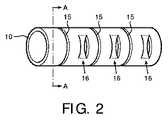
図2は、一体成形の曲げネックの第2の実施(implementation)を例示しているが、今回は単一のチューブ10だけを使用している。チューブ10は、上述のように別個の接続されたリンクに機械加工され、この図には、個別のリンク間の溝15が示されている。制御ケーブル溝のために使用される内側チューブは、この単一チューブの実施において存在しないので、曲げネックを通じて制御ケーブルを運ぶために、一連のリング状の圧痕16(indentations)がチューブの両側に形成される。チューブ壁を通じて2つの平行な切れ目を作られ、次に、切れ目の間の領域が内向きに押し込まれ、図2Aの断面図に明瞭に示されるような圧痕が形成される。圧痕は、頂部及び底部にあり且つ図2の図では見えない、ピボットローブ14(pivot lobes)の線(lines)からチューブの周りに90°ある、チューブの側面に形成される。チューブの対向する側面にある圧痕を通じる制御ケーブルは、曲げネックの遠位端に固定された後に引っ張られる。それらはそれぞれネックを図2の平面の内外に曲げさせる。 FIG. 2 illustrates a second implementation of an integrally formed bending neck, but this time only a
本発明の曲げネックの曲げを制御し且つ調整し得る多くの方法がある。1つの制御技法は、曲げが生じる偏向地点(deflection point)を制御することである。図3は、剛性部材18が、その遠位端が所望の偏向地点にある状態で、曲げネック内に配置される、技術を例示している。この場合、剛性部材は、チューブ18であり、この部分切欠図は、チューブ18の左側へのリンクを示しており、これらのリンクは、それらのピボットローブについて自由に旋回するのに対し、チューブが配置されるリンクは、旋回から不動化されている。偏向地点の位置は、曲げネックの内外への剛性部材18の延伸を調整することによって調整可能である。 There are many ways in which the bending of the bending neck of the present invention can be controlled and adjusted. One control technique is to control the deflection point at which bending occurs. FIG. 3 illustrates a technique in which the
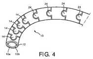
曲げネックのある区画(section)の湾曲によって定められる角度は、図4の曲げネック10によって例示するように、個々のリンクの長さを選択的に決定することによって設定されてよい。この実施において、ピボットローブ14を備える左側へのリンクは比較的短く、これらのリンクの長さは、比較的より短い曲率半径で曲がってよい。ピボットローブ24を備える右側へのより大きなリンクは、比較的より大きな曲率半径で最大限に曲がってよい。加えて、異なる大きさのリンクは、異なるモーメントを有し、それらは、共通して制御されるときに、どのセットのリンクが最初に曲がるかを決定する。より小さなモーメントを有するピボットローブ14を備えるより小さいリンクは、最初に曲がる。これは、例えば、より小さなリンクの遠位先端(図面の左側)での変換器の配置が制御されるときに有用である。曲げネックの両方の区画の関節作動は、溝12内の制御ケーブルを比較的強く引っ張ることによって略所望の位置に設定され、それにより、両方の区画に曲げを引き起こす。変換器がその所望の位置付近にある状態で、ケーブルを軽く引っ張ることを使用して、より小さなリンクの遠位部分のみを移動させ、変換器の最終的な所望の位置を微調整する。 The angle defined by the curvature of the section with the bending neck may be set by selectively determining the length of the individual links, as illustrated by the
隣接するリンクの間で旋回させる程度は、個別のリンクを形成するようチューブを通して機械加工される溝の関数である。図5は、チューブを通じて溝15を機械加工することによって別個のリンク11が形成された曲げネックの部分の部分側面図である。2つのリンクは、ピボットローブの軸の両側で溝を90°開閉する溝15の幅だけ、ピボットローブ14の周りで旋回し得る。より大きな旋回が望まれるならば、溝は、ピボットローブの上下のシータ(theta)の最大の開放(opening)を備える、テーパ状の幅(tapered width)で機械加工され得る。それにより、隣接するリンクの相対的な旋回は、角度シータの寸法まで増大させられる。 The degree to which it is swung between adjacent links is a function of the grooves that are machined through the tube to form individual links. FIG. 5 is a partial side view of a portion of the bending neck where
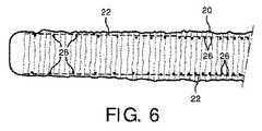
曲げネックの可変の曲げを提供する他の技法は、可変デュロメータを備えるシース内に曲げネックを封入することである。図6は、曲げネックの遠位端から近位端の左側まで可変デュロメータを備える曲げネックに亘るシース20を例示している。シースは右側に剛性が比較的より高く(より高いデュロメータ)、それはシースの遠位端に向かって剛性がより低くなる。制御ケーブルを作動させて曲げネックを曲げると、遠位端は、曲げネックのより高いデュロメータの近位区画よりも容易に、最初に曲がる。シースの長さに沿って使用される材料の選択によって、デュロメータを設定し得る。同じ結果を達成する他の方法は、シースの長さに沿ってシース材料の厚さを変化させることである。図6中の破線22は、シース20が、それがその遠位端に向かう並びに遠位端にあるよりも、その近位(右)端に向かってより厚いことを示している。同じ結果を達成する更に他の方法は、シースを曲げネックに固定する方法を通じてである。図6の実施例において、シース20は、曲げネックの近位部分に沿って近接して離間した地点26で曲げネックに鋲留めされ(tacked)、そして、曲げネックの遠位部分に沿ってより広く離間した地点28で曲げネックに鋲留めされている。これは曲げネックの遠位部分を近位部分よりも容易に且つ直ちに曲げさせる。 Another technique for providing variable bending of the bending neck is to enclose the bending neck within a sheath with a variable durometer. FIG. 6 illustrates a
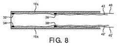
幾つかの実施例では、幾つかのときに、曲げネックの区画を制御可能に曲げ、他のときに、曲げネックを曲げられていない構成にロック(係止)するのが望ましいことがある。図7は、図4の実施態様を用いたこの構成の実施を例示している。この場合には、制御ケーブル通路12を通じて延びる、40−40’及び42−42’の2セットの制御ケーブルがある。ケーブル40−40’の端は、図8中にアンカ地点32及び34によって示すように、曲げネック10の遠位リンク(最左側)への取付けによって固着される。図8において、内側チューブ10bは、例示の明瞭化のために除去されている。ケーブルの他のセット42−42’の端は、アンカ地点36及び38によって示すように、ピボットローブ24を備えるリンクに続く第1のリンクである、リンク11’に固着される。各ケーブルペアが引っ張られ、相補的の方法において緩められると、曲げネックの対応する区画は、図面の平面内で曲げられ、ケーブルセット40−40’は、遠位(小さなリンク)区画を制御し、ケーブルセット42−42’は、近位(より大きなリンク)区画を制御する。しかしながら、ケーブル42−42’の両方を一致して引っ張るときに、近位区画のリンクは一緒に引っ張られ、図7に示すような直線構成にロックされる。曲げネックの遠位区画は、ケーブル40−40’の使用によって依然として制御可能に関節作動させられ得る。ケーブル40及び40’が一致して引っ張られるとき、曲げネック全体は直線構成においてロックされる。よって、多数の制御ケーブル及び選択的なアンカ地点を使用することによって、曲げネックの異なる区画をロックし或いは関節作動させることができる。 In some embodiments, it may be desirable to controllably bend the bend neck section at some times and lock the bend neck to an unbent configuration at other times. FIG. 7 illustrates the implementation of this configuration using the embodiment of FIG. In this case, there are two sets of control cables 40-40 'and 42-42' extending through the
図7の実施において、ピボットローブは、全て曲げネックの前面及び後面にあり、それは両方の関節作動区画が同じ平面、すなわち、図面の平面内で湾曲させられるのを可能にする。単一のセットの制御ケーブル通路12が、この関節作動のために両方のセットのケーブルを収容する。図9は、ピボットローブ14がチューブの前側及び後側に形成され、故に、それらのピボット軸が全て図面の平面に対して法線方向にある、実施を例示している。しかしながら、曲げネックの近位区画のピボットローブ24は、チューブの頂部及び底部に形成され、図面の平面に対して平行なそれらのピボット軸を有する。これは、ピボットローブ14を備える遠位区画を、図面の平面内で湾曲させ得るのに対し、リンクの近位区画を、図面の平面に出入りするよう直角に湾曲させ得ることを意味する。これらの異なる動作(action)を制御するために、異なるセットの制御ケーブルが使用される。ケーブル42及び42’は、ケーブル通路12を通じて延び、アンカ地点32及び34の端に固着される。これらのケーブルは、曲げネックの遠位(最左側)区画の関節作動を制御する。曲げネックの近位区画のための制御ケーブル40及び40’は、ケーブル42及び42’からチューブの円周の周りに90°向けられる。これら制御ケーブルは、通路12に対して90°に向けられる、それらの独自の異なって位置付けられる制御ケーブル通路を通過しなければならない。これらの制御ケーブル40及び40’は、図9の切欠図においてアンカ地点36で固着されるケーブル40によって示されるように、それらが制御するリンクの区画の遠位端に固着される。(ケーブル40’及びそのアンカ地点は、この図において切り取られている)。ケーブル42−42’が引っ張られると、リンクの遠位区画は、関節作動させられ或いはロックされ、ケーブル4−40’が引っ張られると、リンクの近位区画が制御される。 In the implementation of FIG. 7, the pivot lobes are all on the front and back surfaces of the bending neck, which allows both articulation sections to be curved in the same plane, ie the plane of the drawing. A single set of
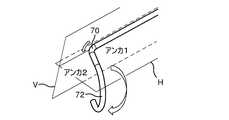
図10a−10bは、本発明の関節作動する超音波プローブの斜視図である。このプローブは、2つの直線状の非関節作動区画60及び62と、2つの関節作動区画70及び72とを有する。図7の実施と同様に、関節作動区画70及び72は、同じ平面、すなわち、図面の水平面H内で関節作動する。図10aにおいて、短い関節作動区画70は、区画70の遠位端に固着されるそのケーブルの制御によって湾曲させられる。図10bにおいて、区画72の遠位端に固着されるケーブルセットは、区画72を関節作動させるために使用される。全ての関節作動は同じ平面内にあるので、両方の区画のピボットローブは、区画の同じ側にあり、両方の区画の制御ケーブルのためには、単一のペアのケーブル通路のみが必要である。 10a-10b are perspective views of the articulating ultrasonic probe of the present invention. The probe has two linear
図11a−11bは、本発明の他の関節作動する超音波プローブの斜視図であり、この超音波プローブは、図9の場合におけるように、2つの平面内で関節作動を実施する。図9と同様に、図11aの関節作動区画72は、関節作動する区画70と比較してチューブの円周の周りに90°向けられた制御ケーブル通路、ピボット軸、及びピボットローブを有する。図11a及び図11bに例示するように、遠位区画72を垂直(V)方向に上下に制御可能に関節作動させることができる。 11a-11b are perspective views of another articulating ultrasonic probe of the present invention, which performs articulation in two planes, as in FIG. Similar to FIG. 9, the
上記の着想の他の変形が当業者の心に直ちに思い浮かぶであろう。ピボットローブは、他の形状及び大きさにおいて形成されてよく、リンク間の旋回(pivoting)は、他のより複雑なピン又はリベット構成によって提供されてよい。しかしながら、本明細書で例示する実施は、単一の又は同心状のチューブのペアから全体的に形成されるという利点を有する。同じに方向付けられるリンクの区画の代わりに、互いに対して90°で旋回するリンクに関節作動する区画を組み入れて、殆どあらゆる方向において湾曲させられる能力を関節作動する区画に与える。 Other variations of the above idea will immediately come to mind to those skilled in the art. The pivot lobe may be formed in other shapes and sizes, and pivoting between links may be provided by other more complex pin or rivet configurations. However, the implementation illustrated herein has the advantage that it is formed entirely from a single or concentric pair of tubes. Instead of the same oriented link section, the articulating section is incorporated into links that pivot at 90 ° relative to each other, giving the articulating section the ability to bend in almost any direction.
Claims (13)
Translated fromJapanese複数の枢動的に接続されるリンクであって、制御された関節作動が可能であるように構成されるリンクと、
当該曲げネックのリンクのある区画に調整可能に延在する剛性部材とを含み、
湾曲構成において、当該曲げネックのリンクの異なる区画が異なる曲率半径を示すよう、当該曲げネックの湾曲のための偏向地点が、前記剛性部材の位置によって決定され、
前記剛性部材は、当該曲げネックのリンクの前記区画に延在するチューブを含み、該チューブが延在する前記リンクは、直線区画において関節作動不能にされることを特徴とする、
曲げネック。An articulated bending neck for an ultrasonic probe,
A link that is more pivotallyconnected,and configuredRu linked asit is possiblecontrolled articulation,
A rigid member adjustably extending to the linked section of the bending neck,
In a curved configuration, the deflection point for bending of the bending neck is determined by the position of the rigid member so that different sections of the bending neck link exhibit different radii of curvature,
The rigid member includes a tube extending to the section of the link of the bending neck, wherein the link from which the tube extends is disabled in a straight section .
Bending neck.
当該曲げネックのリンクの第1の区画は、比較的近接して離間するピボット軸を有し、当該曲げネックのリンクの第2の区画は、比較的より広く離間するピボット軸を有する、
請求項1に記載の曲げネック。And further including a plurality of pivot axes extending through the link, the link being pivotable about the pivot axis;
The first sectionof the bend necklink has a pivot axis that is relatively closely spaced, and the second sectionof the bend necklink has a pivot axis that is relatively wider.
The bending neck according to claim 1.
ピボット軸が、各リンクの前記ピボットローブを通じて延びる、
請求項2に記載の曲げネック。Each link further includes a pivot lobe disposed on opposite sides of the link connecting the link to an adjacent link;
A pivot axis extends through the pivot lobe of each link;
The bending neck according to claim2 .
該取付けの地点は、前記シースの他の区画に沿って離間するよりも、前記シースの1つの区画に沿ってより近接して離間する、
請求項1に記載の曲げネック。A sheath surrounding the pivotally connected link, the sheath indicating a point of attachment to the link along its length;
The point of attachment is more closely spaced along one section of the sheath than is spaced along another section of the sheath;
The bending neck according to claim 1.
前記リンクを通じて延び、前記第1の制御ケーブルから当該曲げリンクに亘って前記リンクの前記区画の前記遠位端に固着される、第2の制御ケーブルとを更に含み、
両方の制御ケーブルが引っ張られるときに、前記リンクの前記区画は、直線構成においてロックされる、
請求項1に記載の曲げネック。Extend through the links, is affixed to the distal end ofa said link section, a first control cable, when pulled,the section of the link to articulation, a first control cable,
The extending through link, the is fixed from the first control cable to the distal end ofthe section of the link over the bending link further includes a second control cable,
When both of the control cable is pulled,the partition of the link is locked in the linear configuration,
The bending neck according to claim 1.
前記リンクを通じて延び、前記第3の制御ケーブルから当該曲げリンクに亘って前記リンクの第2の区画の前記遠位端に固着される、第4の制御ケーブルとを更に含み、
前記第1の区画及び前記第2の区画の関節作動は、別個に制御される、
請求項9に記載の曲げネック。A third control cable extending through the link and secured to the distal end of the second section of the link;
A fourth control cable extending through the link and secured to the distal end of the second section of the link from the third control cable across the bending link;
The articulation of the first compartment and the second compartment is controlled separately;
The bending neck according to claim9 .
ある区画の各リンクの前記ピボットローブは、ある区画の対向する側で列において整列させられ、
前記第1の区画のピボットローブの前記列は、前記第2の区画の前記ピボットローブの前記列と整列させられる、
請求項10に記載の曲げネック。Each link further includes a pivot lobe disposed on opposite sides of the link connecting the link to an adjacent link;
The pivot lobes of each link ofa compartment are aligned in a row on opposite sides of the compartment;
The rows of pivot lobes of the first section are aligned with the rows of pivot lobes of the second section;
The bending neck according to claim10 .
ある区画の各リンクの前記ピボットローブは、ある区画の対向する側で列において整列させられ、
前記第1の区画のピボットローブの前記列は、前記第2の区画のピボットローブの前記列から当該曲げネックの円周の周りに90°配置される、
請求項10に記載の曲げネック。Each link further includes a pivot lobe disposed on opposite sides of the link connecting the link to an adjacent link;
The pivot lobes of each link ofa compartment are aligned in a row on opposite sides of the compartment;
The row of pivot lobes of the first section is disposed 90 ° around the circumference of the bending neck from the row of pivot lobes of the second section.
The bending neck according to claim10 .
Applications Claiming Priority (3)
| Application Number | Priority Date | Filing Date | Title |
|---|---|---|---|
| US201562126750P | 2015-03-02 | 2015-03-02 | |
| US62/126,750 | 2015-03-02 | ||
| PCT/IB2016/051166WO2016139589A2 (en) | 2015-03-02 | 2016-03-02 | Variable configuration bending neck for an articulating ultrasound probe |
Publications (3)
| Publication Number | Publication Date |
|---|---|
| JP2018509973A JP2018509973A (en) | 2018-04-12 |
| JP2018509973A5 JP2018509973A5 (en) | 2018-09-27 |
| JP6440860B2true JP6440860B2 (en) | 2018-12-19 |
Family
ID=55524406
Family Applications (1)
| Application Number | Title | Priority Date | Filing Date |
|---|---|---|---|
| JP2017545736AActiveJP6440860B2 (en) | 2015-03-02 | 2016-03-02 | Variable configuration bending neck for articulating ultrasonic probes |
Country Status (5)
| Country | Link |
|---|---|
| US (1) | US11452501B2 (en) |
| EP (1) | EP3265160B1 (en) |
| JP (1) | JP6440860B2 (en) |
| CN (1) | CN107405468B (en) |
| WO (1) | WO2016139589A2 (en) |
Families Citing this family (9)
| Publication number | Priority date | Publication date | Assignee | Title |
|---|---|---|---|---|
| BR112018009251A2 (en)* | 2016-02-05 | 2019-04-09 | Board Of Regents Of The University Of Texas System | surgical apparatus and customized main controller for a surgical apparatus |
| CN106937897A (en)* | 2017-04-26 | 2017-07-11 | 上海百心安生物技术有限公司 | The Transmission system and preparation method of a kind of bioabsorbable stent |
| WO2019027768A1 (en) | 2017-08-02 | 2019-02-07 | Malekmehr Farshad | Guidewire |
| US10918268B2 (en)* | 2017-08-29 | 2021-02-16 | Opcom Inc. | Insert tube and endoscope using the same |
| JP2021506369A (en)* | 2017-12-12 | 2021-02-22 | ボストン サイエンティフィック サイムド,インコーポレイテッドBoston Scientific Scimed,Inc. | Medical device including ring member and connecting member |
| US11559191B2 (en)* | 2018-10-29 | 2023-01-24 | G.I. View Ltd. | Insertion unit for medical instruments and an intubation system thereof |
| US10856841B1 (en)* | 2020-01-24 | 2020-12-08 | King Saud University | Ultrasonic imaging probe |
| WO2023064510A1 (en)* | 2021-10-13 | 2023-04-20 | Hornak David P | Articulation devices, systems, and methods |
| CN114534067A (en)* | 2022-02-23 | 2022-05-27 | 南通伊诺精密塑胶导管有限公司 | Controllable guiding directional catheter |
Family Cites Families (46)
| Publication number | Priority date | Publication date | Assignee | Title |
|---|---|---|---|---|
| DE3829603A1 (en)* | 1988-09-01 | 1990-03-15 | Kontron Holding Ag | ULTRASONIC DOSCOPE DEVICE |
| DE9012370U1 (en)* | 1990-08-29 | 1990-12-06 | Billino, Helmut, 8000 München | Suction catheter |
| JP3143166B2 (en) | 1991-10-22 | 2001-03-07 | オリンパス光学工業株式会社 | Endoscope |
| JPH05253173A (en)* | 1992-03-13 | 1993-10-05 | Olympus Optical Co Ltd | Curving device |
| JP4096325B2 (en)* | 1998-12-14 | 2008-06-04 | 正喜 江刺 | Active capillary and method for manufacturing the same |
| US6887235B2 (en) | 1999-03-24 | 2005-05-03 | Micrus Corporation | Variable stiffness heating catheter |
| US6364828B1 (en)* | 2000-01-06 | 2002-04-02 | Hubert K. Yeung | Elongated flexible inspection neck |
| JP2002177201A (en)* | 2000-10-02 | 2002-06-25 | Olympus Optical Co Ltd | Endoscope |
| US7250027B2 (en) | 2002-05-30 | 2007-07-31 | Karl Storz Endovision, Inc. | Articulating vertebrae with asymmetrical and variable radius of curvature |
| JP2004105289A (en) | 2002-09-13 | 2004-04-08 | Olympus Corp | Ultrasonic endoscope |
| US7410483B2 (en)* | 2003-05-23 | 2008-08-12 | Novare Surgical Systems, Inc. | Hand-actuated device for remote manipulation of a grasping tool |
| CN1870930A (en)* | 2003-08-20 | 2006-11-29 | 新引导系统公司 | Activated polymer articulated instruments and methods of insertion |
| WO2005113057A1 (en) | 2004-05-17 | 2005-12-01 | C. R. Bard, Inc. | Articulated catheter |
| JP2005334050A (en) | 2004-05-24 | 2005-12-08 | Fujinon Corp | Angle section of endoscope |
| US7678117B2 (en)* | 2004-06-07 | 2010-03-16 | Novare Surgical Systems, Inc. | Articulating mechanism with flex-hinged links |
| DE102004027850A1 (en) | 2004-06-08 | 2006-01-05 | Henke-Sass Wolf Gmbh | Bendable section of an introducer tube of an endoscope and method for its manufacture |
| JP4477519B2 (en)* | 2005-02-14 | 2010-06-09 | オリンパス株式会社 | Endoscope |
| US8052597B2 (en) | 2005-08-30 | 2011-11-08 | Boston Scientific Scimed, Inc. | Method for forming an endoscope articulation joint |
| JP2007236751A (en) | 2006-03-10 | 2007-09-20 | Olympus Corp | Endoscope insertion section |
| US8679097B2 (en)* | 2005-12-20 | 2014-03-25 | Orthodynamix Llc | Method and devices for minimally invasive arthroscopic procedures |
| US8172758B2 (en)* | 2006-03-06 | 2012-05-08 | Imacor Inc. | Transesophageal ultrasound probe with an adaptive bending section |
| JP2009528910A (en)* | 2006-03-06 | 2009-08-13 | イマコー・エルエルシー | Transesophageal ultrasound probe with adjustable bending section |
| JP2007307068A (en) | 2006-05-17 | 2007-11-29 | Olympus Corp | Joint ring connecting body for insertion portion of endoscope and method for producing the same |
| JP2008259634A (en) | 2007-04-11 | 2008-10-30 | Olympus Corp | Connection structure of flexible tube for endoscope and annular connection member |
| JP2008295773A (en) | 2007-05-31 | 2008-12-11 | Olympus Corp | Curved tube of endoscope, endoscope, and method for producing curved tube of endoscope |
| US8864675B2 (en)* | 2007-06-28 | 2014-10-21 | W. L. Gore & Associates, Inc. | Catheter |
| WO2010091309A1 (en)* | 2009-02-06 | 2010-08-12 | Endoclear, Llc | Methods for cleaning endotracheal tubes |
| DE102009017175B4 (en) | 2009-04-09 | 2011-05-05 | Richard Wolf Gmbh | Method for producing a bendable tube |
| JP5404154B2 (en) | 2009-04-21 | 2014-01-29 | オリンパス株式会社 | Endoscope bending section and manufacturing method of bending tube |
| US9254123B2 (en)* | 2009-04-29 | 2016-02-09 | Hansen Medical, Inc. | Flexible and steerable elongate instruments with shape control and support elements |
| DE102009042488A1 (en)* | 2009-05-29 | 2010-12-02 | Aesculap Ag | Control device for use in endoscope, has proximal and distal end sections and center section, where proximal and distal end sections have articulated zone |
| US20100312056A1 (en) | 2009-06-03 | 2010-12-09 | Gyrus, ACMI, Inc. | Endoscope shaft |
| JP2011067423A (en) | 2009-09-25 | 2011-04-07 | Olympus Corp | Endoscope insertion part and manufacturing method of the same |
| WO2011041571A2 (en)* | 2009-10-01 | 2011-04-07 | Kardium Inc. | Medical device, kit and method for constricting tissue or a bodily orifice, for example, a mitral valve |
| CN102413863A (en) | 2009-10-14 | 2012-04-11 | 奥林巴斯医疗株式会社 | Flexible medical tube and insertion part of medical instrument |
| CN103857434B (en)* | 2011-06-28 | 2017-11-24 | 费雪派克医疗保健有限公司 | Improved medical tube |
| US8672206B2 (en)* | 2011-10-25 | 2014-03-18 | Covidien Lp | Apparatus for endoscopic procedures |
| EP2732751A4 (en) | 2011-12-06 | 2015-04-08 | Olympus Medical Systems Corp | FLEXIBLE JOINT |
| JP6082237B2 (en) | 2011-12-09 | 2017-02-15 | 株式会社トクヤマ | Manufacturing method of silicon substrate having texture structure |
| WO2013106444A1 (en) | 2012-01-10 | 2013-07-18 | Boston Scientific Scimed, Inc. | A steerable medical device having an imaging system |
| JP6034573B2 (en)* | 2012-02-28 | 2016-11-30 | テルモ株式会社 | Flexible tube for medical device and medical device |
| US8967204B2 (en) | 2012-08-24 | 2015-03-03 | Olympus Medical Systems Corporation | Curved pipe for endoscopes |
| JP2014233534A (en)* | 2013-06-04 | 2014-12-15 | コニカミノルタ株式会社 | Medical tube, and method for manufacturing the same |
| WO2016056417A1 (en)* | 2014-10-06 | 2016-04-14 | オリンパス株式会社 | Endoscope |
| EP3593700A1 (en)* | 2014-12-05 | 2020-01-15 | Fortimedix Surgical B.V. | Method for manufacturing a steerable instrument and such steerable instrument |
| CN107405055B (en)* | 2015-03-02 | 2020-08-28 | 皇家飞利浦有限公司 | One-piece bending neck for articulating ultrasound probe |
- 2016
- 2016-03-02JPJP2017545736Apatent/JP6440860B2/enactiveActive
- 2016-03-02WOPCT/IB2016/051166patent/WO2016139589A2/ennot_activeCeased
- 2016-03-02CNCN201680013006.XApatent/CN107405468B/enactiveActive
- 2016-03-02USUS15/551,735patent/US11452501B2/enactiveActive
- 2016-03-02EPEP16709596.7Apatent/EP3265160B1/enactiveActive
Also Published As
| Publication number | Publication date |
|---|---|
| US20190117193A1 (en) | 2019-04-25 |
| EP3265160A2 (en) | 2018-01-10 |
| WO2016139589A3 (en) | 2016-10-27 |
| WO2016139589A2 (en) | 2016-09-09 |
| US11452501B2 (en) | 2022-09-27 |
| CN107405468A (en) | 2017-11-28 |
| EP3265160B1 (en) | 2018-12-19 |
| JP2018509973A (en) | 2018-04-12 |
| CN107405468B (en) | 2020-08-18 |
Similar Documents
| Publication | Publication Date | Title |
|---|---|---|
| JP6440860B2 (en) | Variable configuration bending neck for articulating ultrasonic probes | |
| CN107405055B (en) | One-piece bending neck for articulating ultrasound probe | |
| US20200275983A1 (en) | Steerable tube | |
| US11627866B2 (en) | Method for manufacturing an endoscope insertion tube, and endoscope having an insertion tube | |
| US9204783B2 (en) | Elongate medical device with articulating portion | |
| JP7692348B2 (en) | joint | |
| US6585717B1 (en) | Deflection structure | |
| CN108992104B (en) | Articulated link structure exhibiting preferential bending and associated method | |
| EP2949262B1 (en) | Articulating mechanism with flex-hinged links | |
| US20170095138A1 (en) | Endoscope bending tube and endoscope provided with endoscope bending tube | |
| CN112969398B (en) | Method for manufacturing insertion tube of endoscope and endoscope having insertion tube | |
| TWI819471B (en) | A steerable arm for use in endoscopic surgical procedures | |
| JP7671332B2 (en) | Patterned Tube | |
| CN119235462B (en) | surgical robots | |
| JP7730614B2 (en) | Steerable, flexible robotic endoscopic instruments for minimally invasive procedures | |
| CN120788744A (en) | Steerable arm with sections curved in different planes |
Legal Events
| Date | Code | Title | Description |
|---|---|---|---|
| A521 | Request for written amendment filed | Free format text:JAPANESE INTERMEDIATE CODE: A523 Effective date:20180817 | |
| A621 | Written request for application examination | Free format text:JAPANESE INTERMEDIATE CODE: A621 Effective date:20180817 | |
| A871 | Explanation of circumstances concerning accelerated examination | Free format text:JAPANESE INTERMEDIATE CODE: A871 Effective date:20180817 | |
| TRDD | Decision of grant or rejection written | ||
| A975 | Report on accelerated examination | Free format text:JAPANESE INTERMEDIATE CODE: A971005 Effective date:20181009 | |
| A01 | Written decision to grant a patent or to grant a registration (utility model) | Free format text:JAPANESE INTERMEDIATE CODE: A01 Effective date:20181023 | |
| A61 | First payment of annual fees (during grant procedure) | Free format text:JAPANESE INTERMEDIATE CODE: A61 Effective date:20181120 | |
| R150 | Certificate of patent or registration of utility model | Ref document number:6440860 Country of ref document:JP Free format text:JAPANESE INTERMEDIATE CODE: R150 | |
| R250 | Receipt of annual fees | Free format text:JAPANESE INTERMEDIATE CODE: R250 | |
| R250 | Receipt of annual fees | Free format text:JAPANESE INTERMEDIATE CODE: R250 | |
| R250 | Receipt of annual fees | Free format text:JAPANESE INTERMEDIATE CODE: R250 | |
| R250 | Receipt of annual fees | Free format text:JAPANESE INTERMEDIATE CODE: R250 |