JP6440385B2 - Robot arm, display device and robot system - Google Patents
Robot arm, display device and robot systemDownload PDFInfo
- Publication number
- JP6440385B2 JP6440385B2JP2014119369AJP2014119369AJP6440385B2JP 6440385 B2JP6440385 B2JP 6440385B2JP 2014119369 AJP2014119369 AJP 2014119369AJP 2014119369 AJP2014119369 AJP 2014119369AJP 6440385 B2JP6440385 B2JP 6440385B2
- Authority
- JP
- Japan
- Prior art keywords
- robot arm
- display
- robot
- arm
- state
- Prior art date
- Legal status (The legal status is an assumption and is not a legal conclusion. Google has not performed a legal analysis and makes no representation as to the accuracy of the status listed.)
- Active
Links
Images


Classifications
- B—PERFORMING OPERATIONS; TRANSPORTING
- B25—HAND TOOLS; PORTABLE POWER-DRIVEN TOOLS; MANIPULATORS
- B25J—MANIPULATORS; CHAMBERS PROVIDED WITH MANIPULATION DEVICES
- B25J9/00—Programme-controlled manipulators
- B25J9/16—Programme controls
- B25J9/1674—Programme controls characterised by safety, monitoring, diagnostic
- B—PERFORMING OPERATIONS; TRANSPORTING
- B25—HAND TOOLS; PORTABLE POWER-DRIVEN TOOLS; MANIPULATORS
- B25J—MANIPULATORS; CHAMBERS PROVIDED WITH MANIPULATION DEVICES
- B25J9/00—Programme-controlled manipulators
- B25J9/0084—Programme-controlled manipulators comprising a plurality of manipulators
- B—PERFORMING OPERATIONS; TRANSPORTING
- B25—HAND TOOLS; PORTABLE POWER-DRIVEN TOOLS; MANIPULATORS
- B25J—MANIPULATORS; CHAMBERS PROVIDED WITH MANIPULATION DEVICES
- B25J9/00—Programme-controlled manipulators
- B25J9/16—Programme controls
- B25J9/1656—Programme controls characterised by programming, planning systems for manipulators
- B25J9/1664—Programme controls characterised by programming, planning systems for manipulators characterised by motion, path, trajectory planning
- B—PERFORMING OPERATIONS; TRANSPORTING
- B25—HAND TOOLS; PORTABLE POWER-DRIVEN TOOLS; MANIPULATORS
- B25J—MANIPULATORS; CHAMBERS PROVIDED WITH MANIPULATION DEVICES
- B25J9/00—Programme-controlled manipulators
- B25J9/16—Programme controls
- B25J9/1679—Programme controls characterised by the tasks executed
- B25J9/1682—Dual arm manipulator; Coordination of several manipulators
- G—PHYSICS
- G05—CONTROLLING; REGULATING
- G05B—CONTROL OR REGULATING SYSTEMS IN GENERAL; FUNCTIONAL ELEMENTS OF SUCH SYSTEMS; MONITORING OR TESTING ARRANGEMENTS FOR SUCH SYSTEMS OR ELEMENTS
- G05B2219/00—Program-control systems
- G05B2219/20—Pc systems
- G05B2219/24—Pc safety
- G05B2219/24092—Warning display lights, lamps, leds on module
- Y—GENERAL TAGGING OF NEW TECHNOLOGICAL DEVELOPMENTS; GENERAL TAGGING OF CROSS-SECTIONAL TECHNOLOGIES SPANNING OVER SEVERAL SECTIONS OF THE IPC; TECHNICAL SUBJECTS COVERED BY FORMER USPC CROSS-REFERENCE ART COLLECTIONS [XRACs] AND DIGESTS
- Y10—TECHNICAL SUBJECTS COVERED BY FORMER USPC
- Y10T—TECHNICAL SUBJECTS COVERED BY FORMER US CLASSIFICATION
- Y10T74/00—Machine element or mechanism
- Y10T74/20—Control lever and linkage systems
- Y10T74/20207—Multiple controlling elements for single controlled element
- Y10T74/20305—Robotic arm
Landscapes
- Engineering & Computer Science (AREA)
- Robotics (AREA)
- Mechanical Engineering (AREA)
- Manipulator (AREA)
- Numerical Control (AREA)
Description
Translated fromJapanese本発明は、他のロボットアームと協働するロボットアーム、表示装置およびロボットシステムに関するものである。The present invention relatesto a robot arm, a display device, and a robot systemthat cooperate with other robot arms .
近年、例えば小型で複雑な構造を持つ工業製品の組立に関しても工程の自動化の要求が高まっており、この種の製品は小型の産業用ロボットで高速かつ精密な組付けを行う必要がある。また、海外生産との競争力を確保するなどの見地から、コストを抑えた生産体制の確立が必須であり、一つのロボットが多くの組立工程を担い、高速かつ高精度で安定して止まらない生産性の高い生産ラインの確立が望まれている。 In recent years, for example, assembling of industrial products having a small and complicated structure has been increasingly demanded for process automation, and this type of product needs to be assembled with a small industrial robot at high speed and with precision. In addition, from the standpoint of ensuring competitiveness with overseas production, it is essential to establish a production system that keeps costs down, and a single robot is responsible for many assembly processes, and does not stop stably at high speed and high accuracy. Establishment of a production line with high productivity is desired.
このような高効率な生産ラインを実現するために、複腕(複数アーム)構成の産業用ロボットアームを用いて、それぞれの手先に握らせた部品を作業台上の部品に精密に組み付けることがある。このようなロボットシステムにおいてロボットに組み付け作業を教示する場合、複数の教示者が作業を行う場合がある。例えば、いわゆるティーチングペンダントのような教示装置によってロボットアームを操作する作業者と、部品同士を目視し続けて組み付けの具合や成否を監視する作業者に分かれて作業することがある。前者の作業者のことを「操作役」、後者の作業者のことを「監視役」ということがある。 In order to realize such a highly efficient production line, a multi-arm (multi-arm) industrial robot arm can be used to precisely assemble the parts gripped by each hand onto the parts on the workbench. is there. When teaching assembly work to a robot in such a robot system, a plurality of teachers may perform the work. For example, there are cases where the work is divided into an operator who operates the robot arm with a teaching device such as a so-called teaching pendant and an operator who keeps looking at the parts and monitors the state of assembly or success. The former worker may be referred to as an “operator”, and the latter worker may be referred to as a “supervisor”.
複数アーム構成のロボット装置において教示操作の対象とするロボットアームは、監視役と操作役が口頭によるコミュニケーションをとって、取り決められる。このようにして、これから教示操作の対象とするロボットアームのことを「取り決めアーム」ということがある。 The robot arm that is the target of the teaching operation in the robot apparatus having a plurality of arms is determined by verbal communication between the supervisor and the operator. In this way, the robot arm that is the subject of the teaching operation is sometimes referred to as the “arrangement arm”.
この取り決めアームの教示作業では、監視役は、取り決めアームの近傍で待機し、取り決めアームの手先に視線と意識を集中させている。この場合、操作役が取り決めアームに対して行った操作の結果は、ティーチングペンダント(以下、TPという)上にしか表示されないため、監視役はアームの動作可否状態を直接知ることは出来なかった。 In this arrangement arm teaching work, the supervisor waits in the vicinity of the arrangement arm and concentrates his gaze and consciousness on the tip of the arrangement arm. In this case, since the result of the operation performed by the operating combination on the agreed arm is displayed only on the teaching pendant (hereinafter referred to as TP), the monitoring combination cannot directly know whether the arm is operable or not.
ここで、「動作可否状態」とは特定操作(例えばTPによるジョグ操作やインチング操作)で直ちにロボットアームの動作が開始可能か否かの状態をいう。一般に、ロボットアームに対する教示は、TPの操作によって、現在の位置姿勢から次の教示点へ向かって実際にロボットアームを動作させることによって行われる。このような教示操作は、例えばTPの特定操作によって、TP(あるいはロボットシステム全体)を教示操作を行えるモード(後述の教示モード)に移行させることによって可能となる。あるいは、デッドマンキー(スイッチ)のようなイネーブルスイッチを採用したTPでは、イネーブルスイッチをイネーブル状態にして初めてそのような教示操作が可能となる。 Here, the “operation availability state” refers to a state of whether or not the robot arm can be immediately started by a specific operation (for example, jog operation or inching operation by TP). In general, teaching to a robot arm is performed by actually operating the robot arm from the current position and orientation toward the next teaching point by operating TP. Such a teaching operation can be performed by, for example, shifting the TP (or the entire robot system) to a mode in which a teaching operation can be performed (a teaching mode described later) by a specific operation of the TP. Alternatively, in a TP that employs an enable switch such as a deadman key (switch), such teaching operation can be performed only after the enable switch is enabled.
例えば上記のようなモード切り換えやスイッチ操作によって、教示操作が可能なモード、すなわち、教示モードにロボット装置を移行させることができる。この教示モードに入ると例えばロボットアームの関節を駆動するサーボモータがいわゆるサーボオン状態に切り換えられる。また、ロボットアームの各関節の動きをロックするブレーキなどが設けられている場合には、各関節のブレーキが係止状態から開放される。このような切り換えによって、続いて行われるTPの教示操作に応じてロボットアームを動作させることができるようになる。すなわち、教示モードであるとき動作可否状態は動作可能となり、教示モード以外のとき動作不可能となる。 For example, the robot apparatus can be shifted to a mode in which a teaching operation can be performed, that is, a teaching mode, by mode switching or switch operation as described above. When this teaching mode is entered, for example, the servo motor that drives the joint of the robot arm is switched to a so-called servo-on state. Further, when a brake or the like that locks the movement of each joint of the robot arm is provided, the brake of each joint is released from the locked state. By such switching, the robot arm can be operated in accordance with the subsequent TP teaching operation. That is, the operation availability state is operable when in the teaching mode, and operation is not possible when in a mode other than the teaching mode.
旧来は、監視役と操作役のロボットアームの動作可否状態の情報交換は、例えば口頭によるコミュニケーションによってのみ行われていた。しかしながら、このような構成、作業形態では、操作役が合図を送るのを忘れたままロボットアームを動作させてしまい、例えば取り決めアームが動くと思っていない監視役にアームを衝突させてしまうような可能性がある。 Traditionally, the information exchange of the operational status of the monitoring arm and the operating robot arm has been performed only by verbal communication, for example. However, in such a configuration and work mode, the robot arm is operated while the operator forgets to send a signal, for example, the arm is collided with a supervisor who does not think that the negotiating arm moves. there is a possibility.
この点に鑑み、ロボットアーム、もしくはロボットアーム近傍に動作可否を示す表示器を設ける表示制御装置が提案されている(例えば下記の特許文献1)。特許文献1の複腕構成のロボットシステムでは、複数のロボットアームにそれぞれ(またはロボットアーム近傍にそれぞれ)表示器が設けられ、これらの表示器によって、それぞれ当該のロボットアーム動作可否を示すようになっている。 In view of this point, a display control device has been proposed in which a display indicating whether or not the robot arm is operable is provided near the robot arm (for example,
しかしながら、特許文献1の構成では、特定のアームの動作可否状態は、そのアーム、またはその近傍に設けられた表示器によってのみ表示される。このため、特許文献1の構成では取り決めアーム以外のアーム(以下、非取り決めアームという)が教示モードになった場合、取り決めアームに集中している監視役は非取り決めアームが教示モードになったことに気付かない可能性がある。 However, in the configuration of
例えば、取り決めアームを教示し終わった後、今度は非取り決めアームを教示するべく、操作役が取り決めアームを切り換える旨の合図を送ることなく非取り決めアームを教示モードにした場合を考える。このような状況では、特許文献1の構成では、取り決めアームに集中している監視役が非取り決めアームが教示モードとなったことに気がつくのは難しい。なぜなら、特許文献1の構成では、操作役が非取り決めアームを教示モードにしたとき、非取り決めアームが教示モードであることを表示しているのは監視者役の視野外、意識外の非取り決めアーム上の表示器であるためである。特許文献1のような表示方式では、非取り決めアームの方を時折見るような行動を取っていない限り、非取り決めアームが教示モードとなったことに気がつくのは極めて難しい。 For example, consider the case where, after teaching the negotiating arm, the non-arranged arm is set to the teaching mode without sending a signal to the effect that the operating arm switches the negotiating arm in order to teach the non-arranging arm. In such a situation, in the configuration of
本発明は、以上の問題に鑑み、複数のロボットアームが併設されたロボット装置において、あるロボットアームに設けた表示器を介して他のロボットアームの動作可否状態を表示できるようにすることにある。 In view of the above problems, an object of the present invention is to enable a robot apparatus provided with a plurality of robot arms to display an operation availability state of another robot arm via a display provided on the robot arm. .
上記課題を解決するため、本発明においては、他のロボットアームと協働するロボットアームにおいて、前記ロボットアームの先端部に、前記他のロボットアームの状態を表示する表示装置を設けた構成を特徴とする。To solve the above problems, the present invention, wherein a robotarmcooperating withanother robot arm, the distal end ofthe robot arm, a structure in which a display device for displaying the status ofthe other robot arm And
あるいはさらに、本発明においては、前記表示装置に、その表示装置が設けられたロボットアームの状態を表示する構成を特徴とする。
Alternatively, the present invention is characterized in that the display devicedisplays a state of a robot arm provided with the display device.
上記の特徴的な構成により、本発明によれば、ロボットアームの先端部に設けた第1の表示器によって、そのロボットアームとは異なる他のロボットアームの状態を表示することができる。このため、当該のロボットアームの動作に集中している監視役は、視線を移動することなく、同時に他のロボットアームの状態を容易に認識することができる。このため、本発明によれば、例えば監視役が注視しているのとは異なるアームが教示モードに切り換えられても容易にそのことを認識し、必要な回避行動などを取ることができる。 With the above characteristic configuration, according to the present invention, the state of another robot arm different from the robot arm can be displayed by the first indicator provided at the tip of the robot arm. For this reason, the supervisor who concentrates on the operation of the robot arm can easily recognize the state of the other robot arm at the same time without moving the line of sight. Therefore, according to the present invention, for example, even when an arm different from the one watched by the supervisor is switched to the teaching mode, this can be easily recognized, and a necessary avoidance action can be taken.
以下、図面に示す実施例に基づき、発明を実施するための好ましい形態につき詳細に説明する。以下では、2台のロボットアームを併設して成るロボット装置に関する実施例を示す。 Hereinafter, preferred embodiments for carrying out the invention will be described in detail based on the embodiments shown in the drawings. In the following, an embodiment relating to a robot apparatus in which two robot arms are provided will be described.
図1は、本発明を実施したロボットアーム201、211を併設して成るロボット装置200の全体構成を示している。ロボットアーム201、211は、例えば6軸(関節)の垂直多関節ロボットアームであって、その各関節は各関節についてそれぞれ設けられたサーボモータをサーボ制御することにより所望の位置姿勢に制御することができる。 FIG. 1 shows the overall configuration of a
ロボットアーム201、211の動作は、ロボット制御装置202、212によりそれぞれ制御される。ロボット制御装置202、212には、それぞれTP203,213が接続されている。ロボット制御装置202、212に接続されたTP203、213の手動操作を介して各アームの動作をプログラミングすることができる。例えば各ロボットアーム201、211の基準位置(たとえばアーム先端のツール装着面など)を所望の軌跡で移動させる動作のプログラミングは、TP203、213によって軌跡上の教示点を順次指定することによって行われる。この教示点は、例えば、各アームを現在の位置姿勢から、TP203、213の手動操作によって移動させる動作を介して指定することができる。 The operations of the
TP203、213には、例えば、それぞれ対応するロボットアーム201、211を教示するための手動操作が可能な状態にするか、あるいは教示データに基づく自動運転を行う状態にするかの切り替えスイッチが設けられる。また、TP203、213には、それぞれ対応するロボットアーム201、211を教示モードにする教示モード指示スイッチが設けられる。また、TP203、213には、教示作業の動作指示を例えばTP203、213に設けられたディスプレイなどに表示出力させるための動作指示スイッチなどが設けられる。 For example, the TP 203 and 213 are provided with a changeover switch for enabling manual operation for teaching the
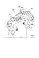
ロボットアーム201および211は、例えばそれぞれ6つの回転関節を有する6自由度マニプレータである。また、ロボットアーム201および211の先端には、作業対象のワークを把持するためのツールとして、図2に示すようなグリッパが設けられる。図2では、ロボットアーム201の先端に設けられるグリッパ2011廻りの構造を示しているが、ロボットアーム211の先端にも同様に構成されたグリッパが設けられる。 The
図2のグリッパ2011は、グリッパ先端部2011bにワークをハンドリングするためのフィンガー2011aを有する。図示したグリッパ2011は、ほぼ円筒断面を有するグリッパ先端部2011b、およびグリッパ基部2011cを有し、これらの内部に、フィンガー2011aを開閉するアクチュエータが設けられる。フィンガー2011aを開閉するアクチュエータは、モータやソレノイドなどの他、空気圧や油圧方式の任意のアクチュエータによって構成されていてよい。グリッパ2011は、ワークを作業場所に搬入、搬出したり、もしくは把持したワークを別のワークに組み付けたりする目的でロボットアームの先端に装着される。 The
また、グリッパ2011の作用部であるグリッパ先端部2011bおよびフィンガー2011aは、ロボットアーム201のツール装着面に対して旋回可能に支持される。グリッパ先端部2011bおよびフィンガー2011aの旋回駆動は例えばグリッパ基部2011c内部に配置されたサーボモータなどによって行われる。あるいはこの旋回駆動のための駆動源は、ロボットアーム201のツール装着部側に配置されていてもよい。 Further, the
図2に示すように、本実施例では、ロボットアーム201のグリッパ2011には、表示器205A、205Bから成る表示装置205を動作可否表示手段として設けてある。 As shown in FIG. 2, in the present embodiment, the
表示器205Aおよび205Bは、例えば一定間隔で配置された複数のLED206Aおよび206Bと、これらLEDを覆う円環(リング)形状の拡散板で構成する。LED206Aまたは206Bを点灯あるいは点滅駆動すると、これらLEDを覆う拡散板により外部に拡散照射される。本実施例では、上記のような構造により、表示器205Aおよび205Bの表示面は、好ましくはグリッパ先端部2011bの全周に渡って配置される。 The
従って、例えば上述のように操作役と監視役の2人の作業者で教示作業を行なう場合、特に監視役はロボットアーム201近傍のどのような位置に居ても表示装置205の表示状態を容易に視認することができる。この表示装置205の視認容易性は、例えば、ロボットアーム201の各関節をどのような姿勢に制御しても、また、グリッパ先端部2011bおよびフィンガー2011aをどのように旋回駆動しても変ることがない。 Accordingly, for example, when the teaching work is performed by the two operators, that is, the operating role and the monitoring role as described above, the display state of the
なお、表示装置205の配置位置は、グリッパ基部2011cの円周面上であってもかまわない。また、表示装置205の配置位置は、(特に監視役の)作業者が大きな視認移動を必要とせず、教示作業中、容易に視認できる位置であれば、グリッパ2011ではなく、ロボットアーム201側であってもかまわない。例えばロボットアーム201の先端に近い位置などに表示装置205を配置してもかまわない。 The arrangement position of the
本実施例では、図2に示したグリッパおよび表示装置の構造は、図1のロボットアーム211側にも設ける。図1では煩雑になるのを避けるためグリッパ関係の参照符号を省略し、例えば、ロボットアーム211に関しては、上記のグリッパに配置した表示装置205と同等の構成として、表示器215Aおよび215Bを有する表示装置215のみを図示している。 In this embodiment, the structure of the gripper and the display device shown in FIG. 2 is also provided on the
本実施例では、表示装置205、215の表示器205A、205B、215A、および215Bは、ロボットアーム201、211の状態、特に動作可否を表示するために用いる。ロボットアーム201の表示器205Aと205B、そしてロボットアーム211の表示器215Aと215Bは、図1、図2に示すように同時に表示内容が確認出来るようそれぞれ隣接して配置されている。 In the present embodiment, the
そして、各アームの第1の表示器205B、215Bは、その表示器が設けられたアームとは異なるアームの状態の表示に、また、第2の表示器205A、215Aはその表示器が設けられたアームの状態の表示に用いる。このように表示器を使い分けることにより、(特に監視役の)作業者は、一方のアーム先端部を注視しているだけでも、そのアームの状態はもちろん、同時にそのアームとは異なる他のアーム状態も視認することができる。 The
例えば、ロボットアーム201の表示器205Bおよびロボットアーム211の表示器215B(第1の表示器)は、各表示器が設けられたアームとは異なる他のロボットアーム211、およびロボットアーム201の状態表示にそれぞれ用いる。 For example, the
また、ロボットアーム201の表示器205Aおよびロボットアーム211の表示器215A(第2の表示器)は、各表示器が設けられたロボットアーム201、およびロボットアーム211の状態表示にそれぞれ用いる。 The
例えば、TP203の操作によってロボットアーム201が教示モードにされたときには、ロボットアーム201の表示器205Aと、ロボットアーム211の表示器215Bを点灯させる。また、TP213の操作によってロボットアーム211が教示モードにされたときには、ロボットアーム211の表示器215Aと、ロボットアーム201の表示器205Bを点灯させる。また、ロボットアーム201および211がともに教示モードでないときは、すべての表示器を消灯させる。このような表示制御は、後述の表示制御装置204A、204B、214A、214Bを介して行う。 For example, when the
ロボットアーム201、211を制御するロボット制御装置202とロボット制御装置212は、例えば基幹LAN230に接続されている。基幹LAN230は、例えばIEEE−802.3規格その他のネットワーク規格に基づき構成されたローカルエリアネットワークである。本実施例のロボット装置では、ロボットアーム201、211の状態、特に動作可否状態に関する情報は、基幹LAN230を介してネットワーク共有される。そして、共有された動作可否状態に基づき、後述の表示制御装置204A、204B、214A、214Bを介して上記の表示器205A、205B、215A、および215Bの表示が制御される。動作可否状態に関する情報の共有は、例えばロボット制御装置202、212が基幹LAN230に接続された不図示のPLC(Programmable Logic Controller)の共有メモリ空間にアクセスすることで実現できる。あるいは、上記の情報共有は、ロボットアームの動作可否状態が変化した時、あるいは間欠的にアームの動作可否状態に対応する情報を格納したパケットをロボット制御装置間で基幹LAN230を介して送受信することなどによっても可能である。上記の共有メモリ空間のアクセスや、パケット交換には、必要に応じて任意のネットワークプロトコルを用いることができる。 The
ここで、それぞれのロボット制御装置202、212から表示制御装置204A、204B、214A、214Bを介して各表示器を点灯制御させるための経路についてさらに詳細に説明する。上記の通り、ロボット制御装置202とロボット制御装置212は基幹LAN230で接続されており、各々のロボットアームの状態に関する情報(あるいは制御情報など)を互いに共有できるようになっている。 Here, a route for controlling the lighting of each display device from the respective
また、図1のロボット制御装置202の表示制御装置204A、204Bは表示器205A、205Bの表示をそれぞれ制御する。また、ロボット制御装置212の表示制御装置214A、214Bは表示器215A、215Bの表示をそれぞれ制御する。これら各表示制御装置および表示器の間の信号線は、例えば図1に破線で示すようにロボットアーム201、211の内部に配線する。 In addition, the
ロボットアーム201の表示制御装置204Aは、上記の通り当該のロボットアーム201の動作可否状態に応じて表示器205Aの表示を制御する。一方、ロボットアーム201の表示制御装置204Bは、当該のロボットアーム201とは異なるロボットアーム211の動作可否状態に応じて表示器205Bの表示を制御する。このため、ロボットアーム201の表示制御装置204Aは、制御装置202から当該のロボットアーム201の動作可否状態に関する信号を受け取り、表示器205Aの表示を制御する。また、同アームの表示制御装置204Bは、基幹LAN230を介して伝達されたロボットアーム211の動作可否状態に関する信号を受け取り、表示器205Bの表示を制御する。 The
また、ロボットアーム211の表示制御装置214Aは、上記の通り当該のロボットアーム211の動作可否状態に応じて表示器215Aの表示を制御する。一方、ロボットアーム211の表示制御装置214Bは、当該のロボットアーム211とは異なるロボットアーム201の動作可否状態に応じて表示器215Bの表示を制御する。このため、ロボットアーム211の表示制御装置214Aは、制御装置212から当該のロボットアーム211の動作可否状態に関する信号を受け取り、表示器215Aの表示を制御する。また、同アームの表示制御装置214Bは、基幹LAN230を介して伝達されたロボットアーム201の動作可否状態に関する信号を受け取り、表示器215Bの表示を制御する。 Further, the
表示制御装置204A、204B、214A、214Bが各表示器の表示を動作可否状態に応じて制御するための信号としては、例えば、ロボットアーム201、211の関節のサーボモータを制御するサーボ信号を用いることができる。例えば、あるロボットアームの教示モードにおいては、当該ロボットアームの全ての関節をティーチングペンダントの手動操作に応じて動作させることが必要である。このため、多くの場合当該アームの各関節のサーボモータは一括して、ON/OFF(イネーブル/ディスエーブル)される。従って、例えば各表示制御装置が各表示器の表示を動作可否状態に応じて制御するための信号としては、この各関節のサーボモータの1つ(あるいは全体)を制御するサーボ信号(いわゆるサーボON信号などのサーボ制御信号)を利用できる。 As a signal for the
以下、本実施例では、表示制御装置204A、204B、214A、214Bが各表示器の表示を動作可否状態に応じて制御するための信号としては、このようなサーボ制御信号を用いるものとする。この場合、表示制御装置204A、204B、214A、214Bは、例えばサーボ制御信号を表示装置205、215の各表示器に入力可能な表示駆動信号に変換するデューティ比(あるいはさらに電圧/電流)変換回路から構成することができる。 Hereinafter, in this embodiment, it is assumed that such a servo control signal is used as a signal for the
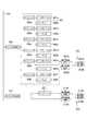
ここで、図8に、図1のロボット制御装置202(または212)、ロボットアーム201(または211)、TP203(213)の制御系の基本構成を示しておく。図8の制御系は、ロボット制御装置2、ロボットアーム1、およびTP3による構成である。図8のロボット制御装置2、およびロボットアーム1は、図1のロボット制御装置202(または212)およびロボットアーム201(または211)に対応し、図8のTP3は、図1のTP203(または213)に対応する。また、図8では図1の基幹LAN230に対応するネットワークとして基幹LAN30を示してある。 Here, FIG. 8 shows a basic configuration of a control system of the robot control device 202 (or 212), robot arm 201 (or 211), and TP 203 (213) of FIG. The control system of FIG. 8 is configured by the
なお、図8では、ロボット制御装置2、ロボットアーム1、およびTP3による基本構成のみを示し、上述の動作可否状態を表示するための表示系の構成は図示を省略してある。 In FIG. 8, only the basic configuration of the
ロボット制御装置2の主制御部は汎用マイクロプロセッサなどから成るCPU501により構成される。CPU501には当該のロボット装置全体を制御するプログラムを格納したROM502、CPU501のワークエリアとして用いられるRAM503が接続される。また、各種の制御データの入出力に用いられる記憶装置として、外部記憶装置504を設けることがある。この外部記憶装置504は、例えば(着脱式の)HDD、SSD、フラッシュメモリなどから構成され、ロボットアーム1の教示(プログラミング)内容や、ROM502のプログラムを更新する制御データの入出力に用いられる。上記各部は不図示の内部バスによって接続される。また、CPU501は任意のインターフェース規格に基づき構成されたインターフェース回路505aを介してTP3と通信し、TP3の操作状態を入力することができる。また、CPU501は上記のネットワーク規格に基づき構成されたインターフェース回路506を介して基幹LAN30と通信し、基幹LAN30を介して上述のように各ロボットアームの状態に関する情報を共有する。 The main controller of the
以下、上記構成における表示制御につき図3を参照して説明する。ここでは、ロボットアーム201を教示操作する場合の表示装置205(ロボットアーム201)、および表示装置215(ロボットアーム211)の表示制御を例示する。 Hereinafter, display control in the above configuration will be described with reference to FIG. Here, display control of the display device 205 (robot arm 201) and the display device 215 (robot arm 211) when teaching the
図3(A)は、ロボットアーム201を手動教示操作する際の制御の流れ(ステップS0〜S4)を示している。図3(A)は、主にTP203からの操作を中心に示してある。各ステップ(S0〜S4)の操作に応じたロボットアーム201各部の制御はロボット制御装置202のCPU501(図8)によって実行される。そのためのCPU501の制御プログラムは、例えば図8のROM502に格納しておくことができる。 FIG. 3A shows a control flow (steps S0 to S4) when the
また、図3(B)、(C)は図3(A)の各ステップ(ステップS0〜S4)に対応して、ロボットアーム201、211の表示装置205、215の表示状態を示している。表示装置205、215の各表示器205A、205B、215A、215Bに関しては、斜線により点灯状態を示すよう図示してある。 3B and 3C show the display states of the
また、図3(D)は図3(A)のステップS0〜S4におけるサーボ制御信号(左側)および表示駆動信号(右側)の変化を示している。本実施例では、表示装置205、215の各表示器の表示状態は、図3(A)の教示操作に応じて変動するサーボ制御信号に基づき、例えば表示制御装置204A、204B、214A、214Bが表示駆動信号を生成することにより実現される。なお、本実施例のようにサーボ制御信号を利用する場合、ロボットアームを教示モードに制御する場合は、そのアームのサーボ制御信号がいわゆるサーボON状態に制御される。このような信号変化の場合、図3(D)に示すように表示制御装置204A、204B、214A、214Bのデューティ比変換(あるいはタイミング変換)は基本的に不要である。そして、これら表示制御装置204A、204B、214A、214Bは、例えば、必要な電圧ないし電流変換を行うよう構成されていればよい。 FIG. 3D shows changes in the servo control signal (left side) and the display drive signal (right side) in steps S0 to S4 in FIG. In the present embodiment, the display state of each display of the
図3(A)の教示操作開始時(ステップS0)には、まだ教示操作が行われていないため、ロボットアーム201、211のサーボ制御信号はいわゆるサーボOFFである。このため、図3(B)、(C)に示すように、ロボットアーム201、211の全ての表示器205A、205B、215A、215Bは消灯している。 At the start of the teaching operation (step S0) in FIG. 3A, since the teaching operation has not yet been performed, the servo control signals of the
ここで、教示操作を行う作業者がTP203からロボットアーム201を教示モードにする(ステップS1)。これに応じて、ロボット制御装置202は、ロボットアーム201を教示モードとするため、当該アームのサーボ制御信号をサーボON状態とする。これにより、表示制御装置204Aを介して表示器205Aが点灯する。 Here, the operator who performs the teaching operation sets the
また、上記のように各アームの状態は、基幹LAN230を介して共有されているため、ロボットアーム201の教示モード(例えば上記サーボ制御信号の状態)は基幹LAN230を介してロボットアーム211のロボット制御装置212に伝達される。これに応じてロボット制御装置212は、ロボットアーム201のサーボ制御信号に応じた信号を表示制御装置214Bに供給して表示駆動信号を生成させ、表示器215Bを点灯させる。一方、この時ロボットアーム211は教示モードにはされておらず、サーボOFFであるため、上記とは逆の制御過程によって、表示器205B、表示器215Aは消灯状態に制御される(以下同様)。 Since the state of each arm is shared via the
TP203で教示操作が行われている間(ステップS2)は、ロボット制御装置202において当該ロボットアーム201のサーボ制御信号がサーボON状態に保持されるため、表示制御装置204Aを介して、表示器205Aが点灯し続ける。この状態はロボット制御装置212に継続して伝達されるため、表示制御装置214Bを介して、表示器215Bは点灯状態が続く。また、依然としてロボットアーム211は教示モードにはされておらず、サーボOFFであるため、上記とは逆の制御過程によって、表示器205B、表示器215Aは消灯し続ける。 While the teaching operation is being performed at TP203 (step S2), the servo control signal of the
教示操作が終わり、作業者がTP203からロボットアーム201を動作不可能にすると(ステップS3)、ロボット制御装置202はサーボ制御信号をサーボOFFとするので、これに応じて表示制御装置204Aを介して表示器205Aは消灯する。この状態はロボット制御装置212に継続して伝達されるため、表示制御装置214Bを介して、表示器215Bは消灯される。表示器205B、表示器215Aは依然として消灯状態である。教示操作終了時(ステップS4)、全ての表示器は消灯状態を保持する。 When the teaching operation is finished and the operator disables the
以上では、ロボットアーム201が教示操作に応じて教示モードに制御される例を示したが、ロボットアーム211が教示モードに制御される場合は、例えば図3(B)、(C)の各表示器の参照符号を相互に交換して読み換えればその時の表示状態になる。 In the above, an example in which the
以上のように、本実施例では、併設されたロボットアーム201、211の先端部付近に、当該アームの状態を表示する表示器と、そのアームとは異なる他のアームの状態を表示する表示器から成る表示装置205、215を設けている。これらの表示装置205、215を構成する表示器205A、205B、215A、215Bは、特に監視役がほとんど視線移動を必要とせず容易に視認することができる。従って、監視役は、注視しているロボットアームのみならず、併設された他のアームの状態、特に動作可否状態を極めて容易に同時に確認できる。このため、TP203、213を介して操作役が合図を忘れて監視役が注視しているのとは異なるロボットアームを教示モードに切り換えたとしても、監視役はそのことを直ちに認識できる。従って、監視役は必要な回避行動を取るなど、必要な措置を講じることができ、安心して作業に集中することができる、また、各ロボットアームの状態を効率よく確認でき、作業の円滑化を図ることができる、という優れた効果がある。 As described above, in the present embodiment, a display that displays the state of the arm and a display that displays the state of another arm that is different from the arm near the distal ends of the
また、本実施例では、上記の特定のアームの状態を表示する表示器と、そのアームとは異なる他のアームの状態を表示する表示器から成る表示装置205、215の表示面は、ロボットアーム先端部のほぼ全周に渡って設けられるよう構成されている。このような構造は表示装置205、215の表示面を図2に示したようにリング(円環)状に構成することにより実現される。このような構造により、特に監視役はロボットアーム201近傍のどのような位置に居ても表示装置205の表示状態を容易に視認することができる。また、ロボットアーム201の各関節をどのような姿勢に制御しても、また、グリッパ先端部2011bおよびフィンガー2011aをどのように旋回駆動しても変ることがない。このため、ロボット装置の動作状況や作業状況に拘らず、作業者は特定のアームの状態と、そのアームとは異なる他のアームの状態を極めて高い視認性をもって確認することができ、安心してロボット装置の教示作業を円滑かつ効率よく実施することができる。 Further, in this embodiment, the display surfaces of the
なお、以上では、2台のロボットアームが併設される構成を示したが、3台以上のロボットアームが併設される構成においても本発明の構成は実施できる。その場合、あるロボットアームに設ける表示装置(例えば上記の205)には、そのアームの状態を示す表示器(上記の205A)の他に、そのアームとは異なる他のアームの状態を表示する表示器を併設されているアームの数だけ配置できる。例えば、上記の表示装置205の場合、当該アームの状態を示す表示器205Aの他に、そのアームとは異なる他のアームの状態を表示する表示器205B、さらに205C、205D…を配置することができる。このような構成においても、上述同様に例えばネットワークを介して併設された各ロボットアームの状態に関する情報を共有することによって、特定のアーム先端の表示装置によって、そのアームとは異なる他のアームの状態を表示することができる。 In the above description, a configuration in which two robot arms are provided is shown. However, the configuration of the present invention can also be implemented in a configuration in which three or more robot arms are provided. In that case, on a display device (for example, 205 described above) provided in a certain robot arm, in addition to a display (205A described above) indicating the state of the arm, a display for displaying the state of another arm different from the arm. You can place as many arms as there are equipment. For example, in the case of the
また、以上では、2台のロボットアーム201、211が併設され、それぞれにロボット制御装置202、212とTP203とTP213が配置される構成を示した。しかしながら、そのアームの状態を示す表示器の他に、そのアームとは異なる他のアームの状態を表示する表示器を有する表示装置205、215を特定のアームの先端部に設ける構成はロボット制御装置やTPの配置態様に拘らず実施できる。 Further, in the above description, a configuration is shown in which two
例えば2台のロボットアームに対して、1組のロボット制御装置とTPが配置され、TPに設けた適当な教示操作対象切り換えスイッチなどによって、各アームの教示を行うような構成においても本発明の構成は実施可能である。この場合、教示操作対象切り換えスイッチの操作によって制御される教示操作対象アームの選択状態に応じて、表示装置205、215のうち適当な表示器の表示状態を変更することができる。すなわち、教示操作対象として選択された(あるいは選択されていない)アームの表示装置205、215のうち適当な表示器の表示状態を点滅や、表示色変更などを行うことができる。このような制御により、作業者は、教示操作対象の切り換えから、特定のアームが教示モードに至るまでの状態を段階的に、確実に把握することができる。 For example, even in a configuration in which a pair of robot control devices and a TP are arranged for two robot arms, and each arm is taught by an appropriate teaching operation target changeover switch provided on the TP. Configuration is possible. In this case, an appropriate display state of the
なお、図1に示したように2台(あるいはそれ以上)のロボットアームを併設し、特定の作業工程を担当させる場合、そのようなロボットアームの配置単位を「セル」などと呼ぶ場合がある。また、そのようなセルを複数、隣接して配置する単位を「ステーション」などと呼ぶ場合がある。図1に示したロボット装置では、例えばロボットアーム201、211を上記の1セルを構成するよう配置し、協働して何らかの組立や加工工程を担当するよう教示することができる。一方、本発明は、表示装置(205、215)が、それらの表示装置が設けられているアームとは異なる他のロボットアームの状態を表示できる表示器(上記の205B、215B…)を備えている点に1つの特徴がある。そして、他のロボットアームの状態を表示する表示器(205B、215B…)は、必ずしも同じセルやステーションといった配置単位に含まれる他のアームの状態を表示するものである必要はない。例えば、他のロボットアームの状態を表示する表示器(205B、215B…)は、隣接、離間状態に拘らず、そのアームが属するのとは別のセルやステーションなどの配置単位に含まれるアームの状態を表示するよう構成してもよい。 When two (or more) robot arms are provided as shown in FIG. 1 and a specific work process is assigned, such a robot arm arrangement unit may be called a “cell” or the like. . A unit in which a plurality of such cells are arranged adjacent to each other may be referred to as a “station”. In the robot apparatus shown in FIG. 1, for example, the
また、以上では、表示装置205、215の表示面は、ロボットアーム先端部のほぼ全周に渡って設けられるものとしたが、例えば作業者の典型的な立ち位置などに応じて、その作業者の最も視認しやすい面(のみ)に配置するようにしてもよい。例えば、表示装置205、215は、操作役や監視役の典型的な立ち位置から見てロボットアームの内側(または外側)の半周面に渡って配置するようにしてもよい。 In the above description, the display surfaces of the
すなわち、表示装置205、215の表示面は、ロボットアーム先端部片側の少なくともほぼ半周(あるいはそれ以上)に渡って配置すればよい。これにより、ロボットアームの位置姿勢などに拘らず作業者がそのアームおよびそのアームとは異なるアームの状態を容易に把握できる、という作用効果の大部分を達成することができる。 That is, the display surfaces of the
なお、以上では、表示装置205、215を、ロボットアームの先端部に対象物を取り扱うツールとして配置されるグリッパ2011に設ける構成を例示した。しかしながら、表示装置205、215を設けるツールはグリッパ(ハンド)などに限定されるものではなく、上記表示装置205、215と同等の表示装置は、ロボットアームに配置される任意のツール(ないしエンドエフェクタ)に設けることができる。また、表示装置205、215と同等の表示装置は、必ずしもツールやエンドエフェクタに配置する必要はなく、例えばロボットアームの先端部付近を構成するリンクの1つに設けるようにしてもよい。 In the above description, the configuration in which the
上記実施例では、表示装置205、215でロボットアームの状態を表示するためにサーボ制御信号を用いる例を示したが、ロボットアームの状態を表示するには、ロボット装置で用いられる他の信号を利用してもよい。以下の実施例では、ロボットアームの関節の動作を規制するブレーキを駆動するブレーキ駆動信号を利用して表示装置の表示駆動信号を生成する例を示す。 In the above embodiment, the servo control signal is used to display the robot arm status on the
ロボットアームでは、各回転関節のサーボモータの駆動電源が遮断された時に、重力に抗して位置を維持するための駆動装置として各関節のサーボモータの駆動軸にブレーキが設けられる。この種のブレーキには、例えば通電時解放型ブレーキが用いられる。この通電時解放型のブレーキは、無通電時はサーボモータの出力軸を制動保持し、通電時はサーボモータの出力軸を解放するよう動作する。通常、ロボット装置の電源投入直後は、ブレーキは無通電状態であり、ロボットアームのサーボモータの駆動軸は制動保持され、ロボットアームはその位置姿勢を保持する。一方、ロボットアームを教示モードにする場合には、各ブレーキに通電し駆動することにより、各関節のサーボモータの駆動軸を解放する。これにより各関節の状態をサーボモータに自由に制御できるようになる。 In the robot arm, a brake is provided on the drive shaft of the servo motor of each joint as a drive device for maintaining the position against gravity when the drive power of the servo motor of each rotary joint is shut off. For this type of brake, for example, a release brake when energized is used. This energized release brake operates to brake and hold the output shaft of the servo motor when not energized, and to release the output shaft of the servo motor when energized. Normally, immediately after the robot apparatus is powered on, the brake is in a non-energized state, the drive shaft of the servo motor of the robot arm is braked and held, and the robot arm holds its position and orientation. On the other hand, when the robot arm is set to the teaching mode, the drive shaft of the servo motor of each joint is released by energizing and driving each brake. As a result, the state of each joint can be freely controlled by the servo motor.
本実施例では、上記のロボットアームの関節に設けられるブレーキを制御するブレーキ制御信号を変換して、特定のアームの状態と、そのアームとは異なる他のアームの状態を表示する表示装置の表示駆動信号を生成する。 In this embodiment, a display of a display device that converts a brake control signal for controlling a brake provided at a joint of the robot arm and displays a state of a specific arm and a state of another arm different from the arm. A drive signal is generated.
図4および図5は、図1と同等の様式で、本実施例のロボット装置の構成を示している。図4と図5で異なるのは、ブレーキ制御信号を利用した表示装置の制御系の配線方式のみであり、対応する部材には各図で同一の参照符号を用いている。また、図4および図5では、図1の200番台の参照符号の代りに300番台の符号を用いており、図4および図5において10および1の桁が図1のものと一致する部材は図1のものと同一ないし同等の部材である。 4 and 5 show the configuration of the robot apparatus of the present embodiment in the same manner as FIG. 4 and 5 differ only in the wiring system of the control system of the display device using the brake control signal, and the same reference numerals are used for corresponding members in the respective drawings. 4 and FIG. 5, the reference numerals of the 300 series are used in place of the reference numerals of the 200 series of FIG. 1, and members whose
図4および図5のロボット装置300は、ロボットアーム301、311を併設して構成される。動作可否表示手段としての表示装置305、315を構成する表示器305A、305B、315A、315Bは、ロボットアーム301、311先端の図1と同等の位置に配置される。表示装置305、315が配置されるグリッパ廻りの構成は、図2に示したのとほぼ同様に構成でき、表示器305A、305B、315A、315Bの配置構造は図1、図2の表示器205A、205B、215A、215Bのものと同じでよい。 The
図4および図5の構成でも、ロボットアーム301、311にはそれぞれ対応するロボット制御装置302、312が配置されており、各ロボット制御装置にはTP303、313がそれぞれ接続されている。 4 and FIG. 5, corresponding
また、表示装置305、315の表示器305A、305B、315A、315Bの表示制御は、表示制御装置304A、304B、314A、314Bによって行われる。本実施例では、表示装置305または315が設けられたアームの状態を表示する表示器305A、315Aは表示制御装置304A、314Aにより制御される。 In addition, display control of the
図4、図5において、表示制御装置304A、314Aは、当該アームの関節の1つに設けられたブレーキ309K、319K(図4にのみ図示)のブレーキ制御信号を表示器305A、315Aの表示駆動信号に変換する。ブレーキ制御信号はロボットアーム301、311の先端に近い関節に配置されたブレーキ309K、319Kから取り出される。 4 and 5, the
そして、図4では、ロボットアーム301、311の内部に配置された表示制御装置304A、314Aに結線されている。一方、図5ではブレーキ制御信号はロボットアーム301、311の先端に近い関節に配置されたブレーキから関節外に導出され、ロボットアーム301、311のリンクの外側に配置された表示制御装置304A、314Aに結線されている。表示制御装置304A、314Aから表示器305A、315Aへの配線は、図4ではアーム内を通り、図5ではアーム外を通るよう結線されている。図4と図5で異なるのは、上記の表示制御装置304A、314Aの配置と、結線方式のみである。 In FIG. 4, the display control devices 304 </ b> A and 314 </ b> A arranged inside the
表示装置305、315の表示器305B、315Bの表示制御を行う表示制御装置304B、314Bは、図1の表示制御装置204B、214Bと同様にロボット制御装置302、312の側に配置されている。 The
ロボット制御装置302、312は、上述の図8に示したものと同様に構成することができる。各ロボットアームの状態に関する情報は、上述の実施例と同様、基幹LAN330を介して共有される。例えば、ブレーキ309K、319K(図4)のブレーキ制御信号の状態を基幹LAN330を介して共有し、表示制御装置204B、214Bは共有された他のアームのブレーキ制御信号の状態に応じて表示器305B、315Bを表示制御する。 The
図6に、上記のブレーキ制御信号を利用した表示制御系の構成をブロック図として示す。図6のロボットアーム301は6関節(6軸:J1〜J6)分のサーボモータ307a〜307fを含み、各サーボモータの動作はそれぞれドライバ306a〜306fを介してロボット制御装置302により制御される。 FIG. 6 is a block diagram showing the configuration of the display control system using the brake control signal. The
図6では、図4のブレーキ309Kに相当するのはブレーキ308eで、このブレーキ308eのブレーキ制御信号が表示制御装置304Aに入力され、表示器305Aの表示駆動信号に変換される。ブレーキ制御信号の状態は、基幹LAN330を介して共有され、ロボット制御装置302を介して表示制御装置304Bに入力される。なお、図6では図示を省略してあるが、ロボットアーム311側も上記のロボットアーム301側と同様に構成されているものとする。 In FIG. 6, the brake 308e corresponds to the
図7(A)〜(D)は、上記実施例の図3と同等の様式で上記構成における表示制御を示している。 7A to 7D show the display control in the above configuration in the same manner as in FIG. 3 of the above embodiment.
図7(A)は、ロボットアーム301を手動教示操作する際の制御の流れ(ステップS0〜S5)を示している。図7(A)は、主にTP303からの操作を中心に示してある。各ステップ(S0〜S5)の操作に応じたロボットアーム301各部の制御はロボット制御装置302のCPU501(図8)によって実行される。そのためのCPU501の制御プログラムは、例えば図8のROM502に格納しておくことができる。 FIG. 7A shows a control flow (steps S0 to S5) when the
また、図7(B)、(C)は図7(A)の各ステップ(ステップS0〜S5)に対応して、ロボットアーム301、311の表示装置305、315の表示状態を示している。表示装置305、315の各表示器305A、305B、315A、315Bに関しては、斜線などにより点灯および点滅状態を示すよう図示してある。 7B and 7C show the display states of the
また、図7(D)は図7(A)のステップS0〜S5におけるブレーキ制御信号(左側)および表示駆動信号(右側)の変化を示している。本実施例では、表示装置305、315の各表示器の表示状態は、図7(A)の教示操作に応じて変動するブレーキ制御信号に基づき、例えば表示制御装置304A、304B、314A、314Bが表示駆動信号を生成することにより実現される。 FIG. 7D shows changes in the brake control signal (left side) and the display drive signal (right side) in steps S0 to S5 in FIG. In this embodiment, the display state of each display of the
本実施例では、図7(D)の左側に示すように、ロボットアームがTPから教示対象として選択されると、ブレーキ制御信号は間欠的にブレーキを通電する状態に切り換えられる。そして、その後、ロボットアームを教示モードに切り換えると、ブレーキ制御信号は対応するブレーキを通電するON状態に切り換わる。アームが教示対象として選択された時、間欠的にブレーキを通電する時のブレーキ制御信号のデューティ比は、例えばブレーキを全開放しない程度(例えば1〜10数KHz程度)に選ばれる。 In this embodiment, as shown on the left side of FIG. 7D, when the robot arm is selected as a teaching target from TP, the brake control signal is switched to a state in which the brake is energized intermittently. After that, when the robot arm is switched to the teaching mode, the brake control signal is switched to the ON state in which the corresponding brake is energized. When the arm is selected as a teaching target, the duty ratio of the brake control signal when the brake is energized intermittently is selected, for example, to such an extent that the brake is not fully released (for example, about 1 to 10 KHz).
ブレーキ制御信号が上記のような信号変化を示す場合、図7(D)の左−>右に示すように表示制御装置304A、304B、314A、314Bは、適当な分周比でデューティ比変換を行う。これにより、当該のアームが教示対象として選択されたことを示すよう、作業者が視認可能な程度の周波数(例えば1〜数Hz程度)で表示器305A、305B、315A、315BをON/OFFする表示駆動信号に変換する。このように、ブレーキが解放されることのない程度のデューティ比の域のPWM波のブレーキ駆動信号を周波数変換し、点滅表示を行う表示駆動信号として利用することができる。 When the brake control signal shows the signal change as described above, the
図7(A)の教示操作開始時(ステップS0)には、ロボットアーム301、311のブレーキ制御信号は駆動信号はデューティ比0%である。この時は、図7(B)、(C)に示すように、ロボットアーム301、311の全ての表示器305A、305B、315A、315Bは消灯状態に制御される。 At the start of the teaching operation in FIG. 7A (step S0), the brake control signals of the
ここで、教示操作を行う作業者がTP303から教示対象としてロボットアーム301を選択すると(ステップS1)、ブレーキ制御信号はデューティ比10%となる。これにより、表示制御装置304A、314Bを介してブレーキ制御信号が表示駆動信号に変換され、表示器305Aと表示器315Bが点滅を開始する(図7(D))。この時、ロボットアーム311は教示対象として選択されておらず、表示器305B、表示器315Aは消灯したままに制御される。なお、表示器305B、315Bの表示状態が基幹LAN330を介して共有されるブレーキ制御信号によって制御されるのは上述の実施例と同じである。 Here, when the operator who performs the teaching operation selects the
次に、作業者がTP303からロボットアーム301を動作可能にする操作を行うと(ステップS2)、これに応じて、ロボット制御装置302は、当該アームのブレーキ制御信号をデューティ比100%の通電状態とする。これにより、ロボットアーム301の各ブレーキが開放状態となる。また、表示制御装置304A、314Bがブレーキ制御信号を変換して生成した表示駆動信号により、表示器305A、表示器315Bは点滅から点灯に表示が変わる。表示器305B、表示器315Aは依然として消灯したままに制御される。 Next, when the operator performs an operation for enabling the
操作役がTP303からアーム301を教示操作している間(ステップS3)、ブレーキ制御信号はデューティ比100%を維持し続け、表示器305A、表示器315Bは点灯状態、表示器305B、表示器315Aは消灯状態を維持する。そして、教示操作が終了すると(S4、S5)、ブレーキ制御信号はデューティ比0%に戻り、表示器305A、305B、315B、315Aは消灯状態に戻る。 While the operator performs teaching operation on the
本実施例において、特定のアームの状態を表示する表示器と、そのアームとは異なる他のアームの状態を表示する表示器から成る表示装置を設ける構造に関する作用効果は上述の実施例1と同様である。本実施例では、上述の実施例1の効果に加えて以下のような作用効果を期待できる。 In this embodiment, the operation and effect relating to the structure in which the display device including the display device for displaying the state of a specific arm and the display device for displaying the state of another arm different from the arm is the same as in the first embodiment described above. It is. In the present embodiment, the following effects can be expected in addition to the effects of the first embodiment.
実施例1では、表示装置205、215の設けられたアームそれ自体の状態を表示する表示器205A、215Aの表示駆動信号をロボットアーム201、211のアーム内部、および関節内部などを経由して先端まで配線する必要があった。これに対して、本実施例では、ロボットアーム301、311の関節のブレーキを制御するブレーキ制御信号を用いて表示装置305、315の設けられたアームそれ自体の状態を表示する表示器305A、315Aの表示駆動信号を生成している。このため、本実施例では、例えばアーム先端に近い関節付近から表示装置305、315の設けられたアーム先端部までブレーキ制御信号ないしこの信号を変換して生成された表示駆動信号の信号線を配線するだけでよい。従って、表示装置305、315の表示制御のために必要な信号線のうち少なくとも1本を実施例1よりも短くすることができる。 In the first embodiment, the display drive signals of the
特に表示装置305、315の表示器305A、315Aは、これらが配置されたアームそれ自体の状態を表示するものであって、特に表示の重要度が高い。そして、本実施例によれば、この表示の重要度が高い表示器305A、315Aのための信号線が断線する可能性を低減でき、信頼性を大きく向上することができる。 In particular, the
また、図5に示したように、表示制御のために必要な信号系はアーム外側に配線するよう構成してもよい。図5では、表示器305A、315Aのための信号線は、アームの関節部からブレーキ制御信号を導出し、リンクの1つに装着した表示制御装置304A、314Aに接続され、そこから表示駆動信号はアームの外側を経由させている。また、表示制御装置304B、314Bから表示器305B、315Bに向かう表示駆動信号の信号線もアームの外側を経由させている。このように自アームないし他アームの状態を表示する表示系をロボットアーム外部に配線することによって、良好なメンテナンス性を得られる。 Further, as shown in FIG. 5, the signal system necessary for display control may be configured to be wired outside the arm. In FIG. 5, the signal lines for the
また、図5のようにアーム外側に自アームないし他アームの状態を表示する表示系の信号系を配線する構成によれば、元々そのような表示系を有していないロボット装置に後から表示系を追加する場合にも比較的容易に対応できる。また、図5のようにアーム外側に表示系のための信号系を配線する構成は、例えばツールをロボットアームに対して着脱可能とする場合でも、信号系のためのコネクタや電極に関する制約が小さい。図5の構成によれば、例えば自アームないし他アームの状態を表示する表示系を有していないツールも着脱可能としたい場合、信号系のためのコネクタやピン配置の共通性を確保するのは比較的容易である。 Further, according to the configuration in which the signal system of the display system for displaying the state of the own arm or the other arm is wired outside the arm as shown in FIG. 5, it is displayed later on the robot apparatus which does not have such a display system. Even when a system is added, it can be handled relatively easily. Further, the configuration in which the signal system for the display system is wired outside the arm as shown in FIG. 5 has little restrictions on the connectors and electrodes for the signal system even when the tool is detachable from the robot arm, for example. . According to the configuration of FIG. 5, for example, when it is desired to attach / detach a tool that does not have a display system for displaying the state of its own arm or another arm, the commonality of the connector and pin arrangement for the signal system is ensured. Is relatively easy.
なお、上述の実施例1で述べた種々の変形例に関しては、本実施例特有の構成と矛盾を生じない限り、本実施例でも実施することができる。 The various modifications described in the first embodiment can be implemented in this embodiment as long as there is no contradiction with the configuration unique to this embodiment.
200、300…ロボット装置、201、211、301、311…ロボットアーム、202、212、302、312…ロボット制御装置、204A、204B、214A、214B、304A、304B、314A、314B…表示制御装置、205A、205B、215A、215B、305A、305B、315A、315B…表示器。200, 300 ... robot device, 201, 211, 301, 311 ... robot arm, 202, 212, 302, 312 ... robot control device, 204A, 204B, 214A, 214B, 304A, 304B, 314A, 314B ... display control device, 205A, 205B, 215A, 215B, 305A, 305B, 315A, 315B... Display.
Claims (13)
Translated fromJapanese前記ロボットアームの先端部に、前記他のロボットアームの状態を表示する表示装置を設けたことを特徴とするロボットアーム。In the robotarmcooperating withanother robot arm,
Roboticarm, characterized in that the distal end ofthe robot arm, is provided a display device for displaying the status ofsaid another robot arm.
前記第1のロボットアームの先端部に、前記第2のロボットアームの状態を表示する第1の表示装置を設けるとともに、 A first display device that displays the state of the second robot arm is provided at the tip of the first robot arm,
前記第2のロボットアームの先端部に、前記第1のロボットアームの状態を表示する第2の表示装置を設けたことを特徴とするロボットシステム。 A robot system comprising a second display device for displaying a state of the first robot arm at a tip of the second robot arm.
Priority Applications (5)
| Application Number | Priority Date | Filing Date | Title |
|---|---|---|---|
| JP2014119369AJP6440385B2 (en) | 2014-06-10 | 2014-06-10 | Robot arm, display device and robot system |
| US14/733,657US20150352720A1 (en) | 2014-06-10 | 2015-06-08 | Robot apparatus |
| EP15171225.4AEP2965874B1 (en) | 2014-06-10 | 2015-06-09 | Robot apparatus |
| CN201510314370.7ACN105313136B (en) | 2014-06-10 | 2015-06-10 | Robot device |
| US16/048,056US11104002B2 (en) | 2014-06-10 | 2018-07-27 | Robot apparatus |
Applications Claiming Priority (1)
| Application Number | Priority Date | Filing Date | Title |
|---|---|---|---|
| JP2014119369AJP6440385B2 (en) | 2014-06-10 | 2014-06-10 | Robot arm, display device and robot system |
Publications (3)
| Publication Number | Publication Date |
|---|---|
| JP2015231651A JP2015231651A (en) | 2015-12-24 |
| JP2015231651A5 JP2015231651A5 (en) | 2017-07-27 |
| JP6440385B2true JP6440385B2 (en) | 2018-12-19 |
Family
ID=53373329
Family Applications (1)
| Application Number | Title | Priority Date | Filing Date |
|---|---|---|---|
| JP2014119369AActiveJP6440385B2 (en) | 2014-06-10 | 2014-06-10 | Robot arm, display device and robot system |
Country Status (4)
| Country | Link |
|---|---|
| US (2) | US20150352720A1 (en) |
| EP (1) | EP2965874B1 (en) |
| JP (1) | JP6440385B2 (en) |
| CN (1) | CN105313136B (en) |
Cited By (1)
| Publication number | Priority date | Publication date | Assignee | Title |
|---|---|---|---|---|
| US12304057B2 (en) | 2020-06-25 | 2025-05-20 | Fanuc Corporation | Control system |
Families Citing this family (25)
| Publication number | Priority date | Publication date | Assignee | Title |
|---|---|---|---|---|
| HK1217847A1 (en) | 2013-03-15 | 2017-01-20 | JIBO, Inc. | Apparatus and methods for providing a persistent companion device |
| US20150314454A1 (en) | 2013-03-15 | 2015-11-05 | JIBO, Inc. | Apparatus and methods for providing a persistent companion device |
| JP6510761B2 (en)* | 2014-04-08 | 2019-05-08 | 川崎重工業株式会社 | Data acquisition system and method |
| USD746886S1 (en)* | 2014-05-23 | 2016-01-05 | JIBO, Inc. | Robot |
| CN104444351B (en)* | 2014-11-07 | 2016-11-02 | 京东方科技集团股份有限公司 | Robot arm and substrate pick-up device |
| JP6630042B2 (en)* | 2014-12-26 | 2020-01-15 | 川崎重工業株式会社 | Dual arm robot teaching system and dual arm robot teaching method |
| SG11201703891RA (en)* | 2014-12-26 | 2017-06-29 | Kawasaki Heavy Ind Ltd | Robot motion program generating method and robot motion program generating apparatus |
| EP3130305B1 (en) | 2015-08-12 | 2021-01-13 | medineering GmbH | Medical holding arm |
| WO2017033365A1 (en)* | 2015-08-25 | 2017-03-02 | 川崎重工業株式会社 | Remote control robot system |
| DE102016104940A1 (en)* | 2016-03-17 | 2017-09-21 | Deutsches Zentrum für Luft- und Raumfahrt e.V. | Protective device for an effector of a manipulator, device for manipulating workpieces and method for actuating a device for manipulating workpieces |
| JP6921488B2 (en)* | 2016-06-09 | 2021-08-18 | キヤノン株式会社 | Signal transmission equipment, signal transmission systems and equipment |
| ITUA20164576A1 (en)* | 2016-06-21 | 2017-12-21 | Alumotion S R L | Collaborative robot, reporting system and process of reporting a movement of a collaborative robot |
| CN106078710B (en)* | 2016-07-06 | 2018-03-06 | 英华达(上海)科技有限公司 | The multi-axis robot of multitask application |
| DE102016118123A1 (en) | 2016-09-26 | 2018-03-29 | Medineering Gmbh | Medical support arm for integration into an operating navigation system |
| JP6382906B2 (en) | 2016-10-17 | 2018-08-29 | ファナック株式会社 | Robot and indicator light installation method for robot |
| SG10201608757PA (en)* | 2016-10-19 | 2018-05-30 | Component Aerospace Singapore Pte Ltd | Method and apparatus for facilitating part verification |
| CN106346481A (en)* | 2016-11-17 | 2017-01-25 | 北京光年无限科技有限公司 | Intelligent robot system for achieving configuration information transplanting and information transplant method |
| US10624738B2 (en) | 2017-02-23 | 2020-04-21 | Edwards Lifesciences Corporation | Heart valve manufacturing devices and methods |
| JP6909626B2 (en)* | 2017-04-28 | 2021-07-28 | タクボエンジニアリング株式会社 | How to display the operating status of a painting robot and a painting robot using it |
| ES2760947T3 (en)* | 2017-06-23 | 2020-05-18 | Comau Spa | Functional set for an industrial machine, specifically for a robot, which includes a functional unit equipped with a safety cover |
| JP6773713B2 (en) | 2018-03-29 | 2020-10-21 | ファナック株式会社 | Robot system |
| JP6878664B2 (en)* | 2020-09-24 | 2021-06-02 | ファナック株式会社 | Robot system |
| JP7567534B2 (en)* | 2021-02-10 | 2024-10-16 | セイコーエプソン株式会社 | Robot System |
| KR102472443B1 (en)* | 2021-05-26 | 2022-12-01 | 주식회사 뉴로메카 | Mobile base of collaborative robot for cooking process |
| JP2024089385A (en)* | 2022-12-21 | 2024-07-03 | 川崎重工業株式会社 | Robot System |
Family Cites Families (21)
| Publication number | Priority date | Publication date | Assignee | Title |
|---|---|---|---|---|
| US4664588A (en)* | 1984-03-09 | 1987-05-12 | Applied Robotics Inc. | Apparatus and method for connecting and exchanging remote manipulable elements to a central control source |
| JP3183355B2 (en)* | 1991-12-20 | 2001-07-09 | 株式会社ダイヘン | Industrial robot control device |
| KR100449429B1 (en)* | 1995-09-14 | 2004-12-13 | 가부시키가이샤 야스가와덴끼 | Robot teaching device |
| US6297742B1 (en)* | 1996-08-22 | 2001-10-02 | Csi Technology, Inc. | Machine monitor with status indicator |
| US5917428A (en)* | 1996-11-07 | 1999-06-29 | Reliance Electric Industrial Company | Integrated motor and diagnostic apparatus and method of operating same |
| US6131299A (en)* | 1998-07-01 | 2000-10-17 | Faro Technologies, Inc. | Display device for a coordinate measurement machine |
| DE10314025B4 (en)* | 2003-03-28 | 2010-04-01 | Kuka Roboter Gmbh | Method and device for controlling a plurality of handling devices |
| JP2005231010A (en)* | 2004-02-23 | 2005-09-02 | Fanuc Ltd | Display device |
| US7479876B2 (en)* | 2005-02-02 | 2009-01-20 | Rockwell Automation Technologies, Inc. | Wireless integrated condition monitoring system |
| JP4990504B2 (en)* | 2005-03-30 | 2012-08-01 | 株式会社ダイヘン | Industrial robot system |
| EP1716983B1 (en)* | 2005-04-19 | 2008-05-14 | COMAU S.p.A. | Process for controlling industrial robots, and related robots, robot systems and computer programs |
| EP1901884B1 (en)* | 2005-06-30 | 2019-02-13 | Intuitive Surgical Operations Inc. | Indicator for tool state communication in multi-arm telesurgery |
| JP4247213B2 (en)* | 2005-07-20 | 2009-04-02 | ファナック株式会社 | Robot system including a plurality of robot control devices and robot control device |
| JP4859706B2 (en)* | 2006-08-29 | 2012-01-25 | 株式会社ダイヘン | Robot control system |
| WO2009097895A1 (en)* | 2008-02-05 | 2009-08-13 | Abb Technology Ab | An industrial robot system |
| JP5375297B2 (en)* | 2009-04-16 | 2013-12-25 | 株式会社安川電機 | Robot system |
| JP5370039B2 (en)* | 2009-09-18 | 2013-12-18 | 株式会社デンソーウェーブ | Robot system |
| JP5474472B2 (en)* | 2009-09-25 | 2014-04-16 | 株式会社ダイヘン | Robot control system |
| JP2012218139A (en)* | 2011-04-14 | 2012-11-12 | Seiko Epson Corp | Motor unit and robot |
| JP2013086223A (en)* | 2011-10-20 | 2013-05-13 | Seiko Epson Corp | Robot, and method for controlling indication of robot's movement |
| US9375841B1 (en)* | 2014-05-28 | 2016-06-28 | Google Inc. | Robotic devices with ambient indications of joint status |
- 2014
- 2014-06-10JPJP2014119369Apatent/JP6440385B2/enactiveActive
- 2015
- 2015-06-08USUS14/733,657patent/US20150352720A1/ennot_activeAbandoned
- 2015-06-09EPEP15171225.4Apatent/EP2965874B1/enactiveActive
- 2015-06-10CNCN201510314370.7Apatent/CN105313136B/enactiveActive
- 2018
- 2018-07-27USUS16/048,056patent/US11104002B2/enactiveActive
Cited By (1)
| Publication number | Priority date | Publication date | Assignee | Title |
|---|---|---|---|---|
| US12304057B2 (en) | 2020-06-25 | 2025-05-20 | Fanuc Corporation | Control system |
Also Published As
| Publication number | Publication date |
|---|---|
| EP2965874A3 (en) | 2016-06-15 |
| EP2965874B1 (en) | 2019-08-21 |
| US11104002B2 (en) | 2021-08-31 |
| JP2015231651A (en) | 2015-12-24 |
| US20150352720A1 (en) | 2015-12-10 |
| CN105313136A (en) | 2016-02-10 |
| CN105313136B (en) | 2018-12-04 |
| EP2965874A2 (en) | 2016-01-13 |
| US20180333856A1 (en) | 2018-11-22 |
Similar Documents
| Publication | Publication Date | Title |
|---|---|---|
| JP6440385B2 (en) | Robot arm, display device and robot system | |
| TWI673148B (en) | Remote operation robot system and operation method thereof | |
| JP6476632B2 (en) | Double arm robot | |
| JP6811635B2 (en) | Robot system and its control method | |
| TWI548957B (en) | Load-control system and load-driving system | |
| WO2020178717A1 (en) | Robotic arm assembly including an end effector and an end effector controller | |
| JP2014217913A (en) | Operation teaching method of parallel link robot and parallel link robot | |
| EP2949419A1 (en) | Gear incorporation system and gear incorporation method | |
| JP2020104256A (en) | Control device of robot system | |
| JP2018037038A (en) | Controller, work control device, multi-axis motion control device, and drive control device | |
| JP2019104099A (en) | Robot hand and control method for robot hand | |
| JP7007791B2 (en) | Robot driving methods, computer programs, and robot systems | |
| JP6414317B2 (en) | Industrial machinery systems | |
| KR101093166B1 (en) | industrial robot apparatus having emergency power connection | |
| KR102420896B1 (en) | Welding robot control system and robot recognition method thereof | |
| WO2014132401A1 (en) | Robot system | |
| JP7205972B2 (en) | Teaching system | |
| CN113442130A (en) | Robot | |
| CN107303674B (en) | Robotic system | |
| Kawasaki et al. | A Co-Thinking Collaborative Manipulator for Solving Combinatorial Optimization Problems | |
| JP2024089385A (en) | Robot System | |
| JPH0577183A (en) | Robot controller | |
| KR20160041123A (en) | Handling robot system and method for controlling the same | |
| JP2017013198A (en) | Parts manufacturing method and robot apparatus |
Legal Events
| Date | Code | Title | Description |
|---|---|---|---|
| A521 | Written amendment | Free format text:JAPANESE INTERMEDIATE CODE: A523 Effective date:20170609 | |
| A621 | Written request for application examination | Free format text:JAPANESE INTERMEDIATE CODE: A621 Effective date:20170609 | |
| A977 | Report on retrieval | Free format text:JAPANESE INTERMEDIATE CODE: A971007 Effective date:20180409 | |
| A131 | Notification of reasons for refusal | Free format text:JAPANESE INTERMEDIATE CODE: A131 Effective date:20180424 | |
| A521 | Written amendment | Free format text:JAPANESE INTERMEDIATE CODE: A523 Effective date:20180618 | |
| TRDD | Decision of grant or rejection written | ||
| A01 | Written decision to grant a patent or to grant a registration (utility model) | Free format text:JAPANESE INTERMEDIATE CODE: A01 Effective date:20181023 | |
| A61 | First payment of annual fees (during grant procedure) | Free format text:JAPANESE INTERMEDIATE CODE: A61 Effective date:20181120 | |
| R151 | Written notification of patent or utility model registration | Ref document number:6440385 Country of ref document:JP Free format text:JAPANESE INTERMEDIATE CODE: R151 |