JP6439615B2 - Ribbon cassette - Google Patents
Ribbon cassetteDownload PDFInfo
- Publication number
- JP6439615B2 JP6439615B2JP2015139573AJP2015139573AJP6439615B2JP 6439615 B2JP6439615 B2JP 6439615B2JP 2015139573 AJP2015139573 AJP 2015139573AJP 2015139573 AJP2015139573 AJP 2015139573AJP 6439615 B2JP6439615 B2JP 6439615B2
- Authority
- JP
- Japan
- Prior art keywords
- spool
- ink ribbon
- ribbon
- cassette case
- cassette
- Prior art date
- Legal status (The legal status is an assumption and is not a legal conclusion. Google has not performed a legal analysis and makes no representation as to the accuracy of the status listed.)
- Active
Links
- 238000004804windingMethods0.000claimsdescription149
- 230000002829reductive effectEffects0.000claimsdescription10
- 238000001514detection methodMethods0.000description67
- 230000002441reversible effectEffects0.000description23
- 238000003780insertionMethods0.000description22
- 230000037431insertionEffects0.000description22
- 238000005520cutting processMethods0.000description17
- 230000002093peripheral effectEffects0.000description17
- 230000007246mechanismEffects0.000description12
- 230000000694effectsEffects0.000description6
- 230000005489elastic deformationEffects0.000description6
- 230000000149penetrating effectEffects0.000description4
- 230000002452interceptive effectEffects0.000description3
- 239000002184metalSubstances0.000description3
- 238000003860storageMethods0.000description3
- 238000011144upstream manufacturingMethods0.000description3
- 238000013459approachMethods0.000description2
- 230000007423decreaseEffects0.000description2
- 230000004048modificationEffects0.000description2
- 238000012986modificationMethods0.000description2
- 239000011347resinSubstances0.000description2
- 229920005989resinPolymers0.000description2
- 239000000758substrateSubstances0.000description2
- 230000008859changeEffects0.000description1
- 238000010586diagramMethods0.000description1
- 238000007599dischargingMethods0.000description1
- 238000010438heat treatmentMethods0.000description1
- 230000002401inhibitory effectEffects0.000description1
- 238000009434installationMethods0.000description1
- 238000005304joiningMethods0.000description1
- 238000004519manufacturing processMethods0.000description1
- 239000000463materialSubstances0.000description1
- 230000004044responseEffects0.000description1
- 230000009466transformationEffects0.000description1
Images


Classifications
- B—PERFORMING OPERATIONS; TRANSPORTING
- B41—PRINTING; LINING MACHINES; TYPEWRITERS; STAMPS
- B41J—TYPEWRITERS; SELECTIVE PRINTING MECHANISMS, i.e. MECHANISMS PRINTING OTHERWISE THAN FROM A FORME; CORRECTION OF TYPOGRAPHICAL ERRORS
- B41J32/00—Ink-ribbon cartridges
- B—PERFORMING OPERATIONS; TRANSPORTING
- B41—PRINTING; LINING MACHINES; TYPEWRITERS; STAMPS
- B41J—TYPEWRITERS; SELECTIVE PRINTING MECHANISMS, i.e. MECHANISMS PRINTING OTHERWISE THAN FROM A FORME; CORRECTION OF TYPOGRAPHICAL ERRORS
- B41J17/00—Mechanisms for manipulating page-width impression-transfer material, e.g. carbon paper
- B41J17/22—Supply arrangements for webs of impression-transfer material
- B41J17/24—Webs supplied from reels or spools attached to the machine
- B—PERFORMING OPERATIONS; TRANSPORTING
- B41—PRINTING; LINING MACHINES; TYPEWRITERS; STAMPS
- B41J—TYPEWRITERS; SELECTIVE PRINTING MECHANISMS, i.e. MECHANISMS PRINTING OTHERWISE THAN FROM A FORME; CORRECTION OF TYPOGRAPHICAL ERRORS
- B41J17/00—Mechanisms for manipulating page-width impression-transfer material, e.g. carbon paper
- B41J17/32—Detachable carriers or holders for impression-transfer material mechanism
- B—PERFORMING OPERATIONS; TRANSPORTING
- B41—PRINTING; LINING MACHINES; TYPEWRITERS; STAMPS
- B41J—TYPEWRITERS; SELECTIVE PRINTING MECHANISMS, i.e. MECHANISMS PRINTING OTHERWISE THAN FROM A FORME; CORRECTION OF TYPOGRAPHICAL ERRORS
- B41J2/00—Typewriters or selective printing mechanisms characterised by the printing or marking process for which they are designed
- B41J2/315—Typewriters or selective printing mechanisms characterised by the printing or marking process for which they are designed characterised by selective application of heat to a heat sensitive printing or impression-transfer material
- B41J2/32—Typewriters or selective printing mechanisms characterised by the printing or marking process for which they are designed characterised by selective application of heat to a heat sensitive printing or impression-transfer material using thermal heads
- B41J2/325—Typewriters or selective printing mechanisms characterised by the printing or marking process for which they are designed characterised by selective application of heat to a heat sensitive printing or impression-transfer material using thermal heads by selective transfer of ink from ink carrier, e.g. from ink ribbon or sheet
Landscapes
- Impression-Transfer Materials And Handling Thereof (AREA)
Description
Translated fromJapanese本発明は、インクリボンを収納するリボンカセットに関する。 The present invention relates to a ribbon cassette that stores an ink ribbon.
従来、印字に使用されるインクリボンを収納するリボンカセットが知られている。例えば、特許文献1に記載のリボンカセットは、カセットケースによって回転自在に支持されたリボンスプール及び巻取スプールを備える。リボンスプールには、インクリボンが巻回されている。巻取スプールは、リボンスプールからインクリボンを引き出し、且つ、文字等の印字に使用されたインクリボンを巻き取る。巻取スプールの下端部には、クラッチバネが設けられている。クラッチバネは、巻取スプールをインクリボンの巻き取り方向とは反対方向に回転させる外力が加えられると、巻取スプールに回転負荷を付与する。これにより、インクリボンに適正なテンションが付与されている状態を保っている。 Conventionally, ribbon cassettes that store ink ribbons used for printing are known. For example, the ribbon cassette described in
従来のリボンカセットでは、例えばユーザがインクリボンを押して、弛ませてしまう場合があった。この場合、従来のリボンカセットは、弛んだ状態のインクリボンを適正なテンションが付与されている状態に戻すことが難しかった。 In the conventional ribbon cassette, for example, the user may press and loosen the ink ribbon. In this case, it has been difficult for the conventional ribbon cassette to return the slackened ink ribbon to a state where an appropriate tension is applied.
本発明の目的は、弛んだ状態のインクリボンを適正なテンションが付与されている状態に戻すことができるリボンカセットを提供することである。 An object of the present invention is to provide a ribbon cassette that can return an ink ribbon in a slack state to a state where an appropriate tension is applied.
本発明の第一態様に係るリボンカセットは、箱状のカセットケースと、前記カセットケースに収納され、前記カセットケースの第一外壁に設けられた第一孔と、前記カセットケースの第二外壁に設けられた第二孔との間で、一部が前記カセットケースから露出するインクリボンと、前記カセットケースによって回転可能に支持され、前記インクリボンの一端側が巻かれた円筒状の第一スプールと、前記カセットケースによって回転可能に支持され、前記インクリボンの他端側が第一部分に連結された円筒状の第二スプールと、前記カセットケースに設けられた係合部と、前記第二スプールの前記第一部分とは異なる第二部分に巻かれたバネ部材とを備え、前記バネ部材は、前記第二部分に巻かれた巻付部と、前記巻付部の第一端部から延設され、前記係合部と係合する延設部とを有し、前記巻付部は、前記第一端部から、前記第二スプールが前記インクリボンを巻き取る際の巻取り方向とは相対的に反対の方向である反対方向に巻かれており、前記第二孔を介して前記第二スプール側から前記インクリボンが引き出される際の第二引出し負荷は、前記第一孔を介して前記第一スプール側から前記インクリボンが引き出される際の第一引出し負荷よりも小さいことを特徴とする。 The ribbon cassette according to the first aspect of the present invention includes a box-shaped cassette case, a first hole accommodated in the cassette case and provided in the first outer wall of the cassette case, and a second outer wall of the cassette case. An ink ribbon partially exposed from the cassette case between the provided second hole, a cylindrical first spool that is rotatably supported by the cassette case and wound around one end of the ink ribbon; A cylindrical second spool that is rotatably supported by the cassette case, the other end of the ink ribbon being connected to the first portion, an engaging portion provided in the cassette case, and the second spool. A spring member wound around a second part different from the first part, wherein the spring member extends from a winding part wound around the second part and a first end of the winding part. An extending portion that engages with the engaging portion, and the winding portion is relative to the winding direction when the second spool winds the ink ribbon from the first end portion. The second pull-out load when the ink ribbon is pulled out from the second spool side through the second hole is wound through the first hole through the first hole. It is smaller than the first drawing load when the ink ribbon is drawn from one spool side.
上記第一態様に係るリボンカセットによれば、巻付部は、延設部が延設されている第一端部から、巻取り方向とは相対的に反対の方向に、第二スプールの第二部分に巻かれている。これにより、巻付部は、第二スプールが巻取り方向に回転した場合に拡径し、第二スプールが巻取り方向とは反対方向に回転した場合に縮径される。例えば、カセットケースから露出している第一孔と第二孔の間のインクリボンの面に対して垂直方向に所定の大きさの外力が付与された場合、第二引出し負荷は第一引出し負荷よりも小さいため、第二スプールが巻取り方向とは反対方向に回転する。この場合、第二スプールの巻取り方向とは反対方向の回転に伴い、バネ部材が巻取り方向とは反対方向に回転する。バネ部材が巻取り方向とは反対方向に回転すると、巻付部が縮径され、延設部が係合部との接触部を支点として弾性変形する。即ち、第二スプールは、延設部が弾性変形した分だけ巻取り方向とは反対方向に回転する。故に、インクリボンは、所定の大きさの外力によって第二スプールから引き出されて弛んだ状態になる。そして、インクリボンが所定の大きさの外力から解放された場合、弾性変形していた延設部が弾性力によって元の状態へ戻り、巻付部が拡径する。これにより、第二スプールが巻取り方向に回転して弛んだ状態であったインクリボンを巻き取るため、インクリボンは適正なテンションが付与されている状態に戻る。従って、リボンカセットは、弛んだ状態のインクリボンを適正なテンションが付与されている状態に戻すことができる。 According to the ribbon cassette according to the first aspect, the winding portion extends from the first end where the extending portion extends to the second spool in a direction relatively opposite to the winding direction. It is wound in two parts. As a result, the winding portion increases in diameter when the second spool rotates in the winding direction, and decreases in diameter when the second spool rotates in the direction opposite to the winding direction. For example, when an external force of a predetermined magnitude is applied in a direction perpendicular to the surface of the ink ribbon between the first hole and the second hole exposed from the cassette case, the second drawer load is the first drawer load. The second spool rotates in the direction opposite to the winding direction. In this case, the spring member rotates in the direction opposite to the winding direction as the second spool rotates in the direction opposite to the winding direction. When the spring member rotates in the direction opposite to the winding direction, the winding portion is reduced in diameter, and the extended portion is elastically deformed with the contact portion with the engaging portion as a fulcrum. That is, the second spool rotates in the direction opposite to the winding direction by the amount of elastic deformation of the extending portion. Therefore, the ink ribbon is pulled out from the second spool by an external force of a predetermined magnitude and is in a slack state. When the ink ribbon is released from an external force having a predetermined size, the extended portion that has been elastically deformed returns to the original state by the elastic force, and the winding portion expands in diameter. As a result, the ink ribbon that has been loosened by rotating in the winding direction of the second spool is taken up, so that the ink ribbon returns to a state in which an appropriate tension is applied. Therefore, the ribbon cassette can return the slackened ink ribbon to a state where an appropriate tension is applied.
本発明の第二態様に係るリボンカセットは、箱状のカセットケースと、前記カセットケースに収納され、前記カセットケースの第一外壁に設けられた第一孔と、前記カセットケースの第二外壁に設けられた第二孔との間で、一部が前記カセットケースから露出するインクリボンと、前記カセットケースによって回転可能に支持され、前記インクリボンの一端側が巻かれた円筒状の第一スプールと、前記カセットケースによって回転可能に支持され、前記インクリボンの他端側が第一部分に連結された円筒状の第二スプールと、前記カセットケースに設けられた係合部と、前記第二スプールの前記第一部分とは異なる第二部分に巻かれたバネ部材とを備え、前記バネ部材は、前記第二部分に巻かれた巻付部と、前記巻付部の第一端部から延設され、前記係合部と係合する延設部とを有し、前記巻付部は、前記第一端部から、前記第二スプールが前記インクリボンを巻き取る際の巻取り方向とは相対的に反対の方向である反対方向に巻かれており、前記係合部は、前記第一スプールの回転中心と前記第二スプールの回転中心と前記第一孔と前記第二孔とで囲まれる領域のうち、前記インクリボンの全てが前記第二スプールによって巻き取られた際のインクリボンの最外周よりも、前記第二スプールの回転中心から離隔する位置に設けられることを特徴とする。第二態様に係るリボンカセットによれば、第一態様と同様の効果を奏することができる。The ribbon cassette according to the second aspect of the present invention includes a box-shaped cassette case, a first hole accommodated in the cassette case and provided in the first outer wall of the cassette case, and a second outer wall of the cassette case. An ink ribbon partially exposed from the cassette case between the provided second hole, a cylindrical first spool that is rotatably supported by the cassette case and wound around one end of the ink ribbon; A cylindrical second spool that is rotatably supported by the cassette case, the other end of the ink ribbon being connected to the first portion, an engaging portion provided in the cassette case, and the second spool. A spring member wound around a second part different from the first part, wherein the spring member extends from a winding part wound around the second part and a first end of the winding part. An extending portion that engages with the engaging portion, and the winding portion is relative to the winding direction when the second spool winds the ink ribbon from the first end portion. The engagement portion issurrounded by the rotation center of the first spool, the rotation center of the second spool, the first hole, and the second hole. Among these, the ink ribbon is provided at a position farther from the rotation center of the second spool than the outermost circumference of the ink ribbon when all of the ink ribbon is wound by the second spool. According to the ribbon cassette which concerns on a 2nd aspect, there can exist an effect similar to a 1st aspect.
本発明の第三態様に係るリボンカセットは、箱状のカセットケースと、前記カセットケースに収納され、前記カセットケースの第一外壁に設けられた第一孔と、前記カセットケースの第二外壁に設けられた第二孔との間で、一部が前記カセットケースから露出するインクリボンと、前記カセットケースによって回転可能に支持され、前記インクリボンの一端側が巻かれた円筒状の第一スプールと、前記カセットケースによって回転可能に支持され、前記インクリボンの他端側が第一部分に連結された円筒状の第二スプールと、前記カセットケースに設けられた係合部と、前記第二スプールの前記第一部分とは異なる第二部分に巻かれたバネ部材とを備え、前記バネ部材は、前記第二部分に巻かれた巻付部と、前記巻付部の第一端部から延設され、前記係合部と係合する延設部とを有し、前記第二スプールに対して前記インクリボンを巻き取る巻取り方向に回転させる外力が付与された場合、前記延設部が前記係合部に接触することによって前記巻付部は拡径される一方、前記第二スプールに対して前記巻取り方向とは反対方向に回転させる外力が付与された場合、前記延設部が前記係合部に接触することによって前記巻付部は縮径されると共に、前記延設部は弾性変形し、前記第二孔を介して前記第二スプール側から前記インクリボンが引き出される際の第二引出し負荷は、前記第一孔を介して前記第一スプール側から前記インクリボンが引き出される際の第一引出し負荷よりも小さいことを特徴とする。第三態様に係るリボンカセットによれば、第一態様と同様の効果を奏することができる。 The ribbon cassette according to the third aspect of the present invention includes a box-shaped cassette case, a first hole accommodated in the cassette case and provided in the first outer wall of the cassette case, and a second outer wall of the cassette case. An ink ribbon partially exposed from the cassette case between the provided second hole, a cylindrical first spool that is rotatably supported by the cassette case and wound around one end of the ink ribbon; A cylindrical second spool that is rotatably supported by the cassette case, the other end of the ink ribbon being connected to the first portion, an engaging portion provided in the cassette case, and the second spool. A spring member wound around a second part different from the first part, wherein the spring member extends from a winding part wound around the second part and a first end of the winding part. And an extending portion that engages with the engaging portion, and when the external force that rotates the second spool in the winding direction for winding the ink ribbon is applied, the extending portion is engaged with the engaging portion. When the winding portion is expanded in diameter by contacting the joint portion, an external force that rotates the second spool in a direction opposite to the winding direction is applied to the extended portion. The winding portion is reduced in diameter by coming into contact with the joining portion, and the extending portion is elastically deformed, and the second portion when the ink ribbon is pulled out from the second spool side through the second hole. The drawing load is smaller than the first drawing load when the ink ribbon is drawn from the first spool side through the first hole. According to the ribbon cassette which concerns on a 3rd aspect, there can exist an effect similar to a 1st aspect.
本発明の第一態様から第三態様に係るリボンカセットにおいて、前記延設部は、前記第一端部から接線方向に延設されてもよい。この場合、延設部が巻付部の第一端部から曲げられて延設される場合に比べ、延設部が接続される巻付部の第一端部への負荷が小さい。故に、弾性変形したバネ部材は、元の形状である延設部が巻付部の第一端部から接線方向に延設されている形状に弾性力によって戻りやすい。従って、リボンカセットは、繰り返し使用によるバネ部材の変形を抑制できる。 The ribbon cassette which concerns on the 3rd aspect from the 1st aspect of this invention WHEREIN: The said extension part may be extended in the tangential direction from the said 1st end part. In this case, the load on the first end portion of the winding portion to which the extension portion is connected is smaller than when the extension portion is bent and extended from the first end portion of the winding portion. Therefore, the elastically deformed spring member is likely to return to the shape in which the extending portion, which is the original shape, is extended in the tangential direction from the first end portion of the winding portion by the elastic force. Therefore, the ribbon cassette can suppress deformation of the spring member due to repeated use.
本発明の第一態様から第三態様に係るリボンカセットにおいて、前記第二スプールは、前記第二スプールの回転中心から離隔する方向に延び、巻き取った前記インクリボンを保持するフランジを備え、前記フランジの径は、前記インクリボンの全てが前記第二スプールによって巻き取られた際のインクリボンの径よりも大きく、前記延設部の一部は、前記インクリボンとは反対側で前記フランジに沿って延び、且つ、前記フランジに接触してもよい。この場合、フランジは、バネ部材がインクリボンに接触することにより、第二スプールによるインクリボンの巻き取りが阻害されることを抑制できる。更に、フランジは、延設部の一部に接触することにより、延設部のフランジ側への変形を抑制できる。 In the ribbon cassette according to the first to third aspects of the present invention, the second spool includes a flange that extends in a direction away from the rotation center of the second spool and holds the wound up ink ribbon. The diameter of the flange is larger than the diameter of the ink ribbon when all of the ink ribbon is wound up by the second spool, and a part of the extended portion is on the flange on the side opposite to the ink ribbon. It may extend along and contact the flange. In this case, the flange can prevent the winding of the ink ribbon by the second spool from being inhibited by the spring member coming into contact with the ink ribbon. Furthermore, the flange can suppress a deformation | transformation to the flange side of an extension part by contacting a part of extension part.
本発明の第一態様から第三態様に係るリボンカセットにおいて、前記第一端部は、前記巻付部のうち、前記第一端部とは反対側の第二端部よりも前記フランジ側に位置してもよい。この場合、巻付部のうち、延設部が延設される第一端部が第二端部よりもフランジ側に位置する。これにより、延設部は、大きく変形することなくフランジに沿って延びることができる。従って、リボンカセットは、延設部のフランジ側への変形を抑制できる。 The ribbon cassette which concerns on the 3rd aspect from the 1st aspect of this invention WHEREIN: The said 1st end part is a said flange side rather than the 2nd end part on the opposite side to the said 1st end part among the said winding parts. May be located. In this case, among the winding portions, the first end portion where the extending portion is extended is located closer to the flange side than the second end portion. Thereby, the extending part can extend along the flange without being greatly deformed. Therefore, the ribbon cassette can suppress deformation of the extending portion toward the flange.
本発明の第一態様から第三態様に係るリボンカセットにおいて、前記延設部は、前記延設部の先端部から、前記延設部の延びる方向とは異なる所定方向に延びる係止部を有してもよい。この場合、係止部は、延設部が係合部から外れることを抑制できる。 In the ribbon cassette according to the first aspect to the third aspect of the present invention, the extending portion has a locking portion extending from a distal end portion of the extending portion in a predetermined direction different from a direction in which the extending portion extends. May be. In this case, the latching part can suppress that an extending part remove | deviates from an engaging part.
本発明の第一態様から第三態様に係るリボンカセットにおいて、前記所定方向は、前記第一端部に対して前記第二スプールの回転中心とは反対の方向であってもよい。この場合、係止部は、第二スプールが巻取り方向とは反対方向に回転した場合に、延設部が係合部から外れることを抑制できる。 In the ribbon cassette according to the first to third aspects of the present invention, the predetermined direction may be a direction opposite to the rotation center of the second spool with respect to the first end portion. In this case, when the second spool rotates in the direction opposite to the winding direction, the locking portion can suppress the extension portion from being detached from the engaging portion.
本発明の第一態様から第三態様に係るリボンカセットにおいて、前記係止部は、前記係合部よりも前記第二スプールの回転中心から離隔する位置において、前記係合部から離隔する位置と前記係合部に接触する位置との間で移動可能であってもよい。カセットケースから露出している第一孔と第二孔の間のインクリボンの面に対して垂直方向に所定の大きさの外力が付与された場合、延設部が弾性変形することにより、係止部が係合部から離隔する位置から、係合部に接触する位置に向かって移動する。この場合、係止部が係合部に接触する位置に移動するまで、インクリボンは弛むことができる。従って、リボンカセットは、より大きく弛んだ状態のインクリボンを適正なテンションが付与されている状態に戻すことができる。 In the ribbon cassette according to the first aspect to the third aspect of the present invention, the locking portion is separated from the engagement portion at a position separated from the rotation center of the second spool than the engagement portion. It may be movable between positions that contact the engaging portion. When an external force of a predetermined size is applied in a direction perpendicular to the surface of the ink ribbon between the first hole and the second hole exposed from the cassette case, the extended portion elastically deforms, The stop portion moves from a position separating from the engaging portion toward a position contacting the engaging portion. In this case, the ink ribbon can be loosened until the locking portion moves to a position where it comes into contact with the engaging portion. Therefore, the ribbon cassette can return the ink ribbon in a more loose state to a state where an appropriate tension is applied.
本発明の第一態様から第三態様に係るリボンカセットにおいて、前記係合部は、前記第一スプールの回転中心と前記第二スプールの回転中心との間、且つ、前記第一スプールの回転中心と前記第二スプールの回転中心とを結ぶ仮想線よりも前記インクリボンが露出している側、且つ、前記インクリボンの全てが前記第一スプールに巻かれた際のインクリボンの最外周よりも、前記第一スプールの回転中心から離隔する位置、且つ、前記インクリボンの全てが前記第二スプールによって巻き取られた際のインクリボンの最外周よりも、前記第二スプールの回転中心から離隔する位置に設けられてもよい。この場合、リボンカセットは、第一スプールに巻かれたインクリボン及び第二スプールに巻き取られたインクリボンと係合部とが互いに干渉することを抑制できる。
本発明の第四態様に係るリボンカセットは、箱状のカセットケースと、前記カセットケースに収納され、前記カセットケースの第一外壁に設けられた第一孔と、前記カセットケースの第二外壁に設けられた第二孔との間で、一部が前記カセットケースから露出するインクリボンと、前記カセットケースによって回転可能に支持され、前記インクリボンの一端側が巻かれた円筒状の第一スプールと、前記カセットケースによって回転可能に支持され、前記インクリボンの他端側が第一部分に連結された円筒状の第二スプールと、前記カセットケースに設けられた係合部と、前記第二スプールの前記第一部分とは異なる第二部分に巻かれたバネ部材とを備え、前記第二スプールは、前記第二スプールの回転中心から離隔する方向に延び、巻き取った前記インクリボンを保持するフランジを備え、前記フランジの径は、前記インクリボンの全てが前記第二スプールによって巻き取られた際のインクリボンの径よりも大きく、前記バネ部材は、前記第二部分に巻かれた巻付部と、前記巻付部の第一端部から延設され、前記係合部と係合する延設部とを有し、前記延設部の一部は、前記インクリボンとは反対側で前記フランジに沿って延び、且つ、前記フランジに接触し、前記巻付部は、前記第一端部から、前記第二スプールが前記インクリボンを巻き取る際の巻取り方向とは相対的に反対の方向である反対方向に巻かれており、前記係合部は、前記インクリボンの全てが前記第二スプールによって巻き取られた際のインクリボンの最外周よりも、前記第二スプールの回転中心から離隔する位置に設けられることを特徴とする。第四態様に係るリボンカセットによれば、第一態様と同様の効果を奏することができる。
本発明の第四態様に係るリボンカセットにおいて、前記第一端部は、前記巻付部のうち、前記第一端部とは反対側の第二端部よりも前記フランジ側に位置してもよい。この場合、リボンカセットは、延設部のフランジ側への変形を抑制できる。
本発明の第五態様に係るリボンカセットは、箱状のカセットケースと、前記カセットケースに収納され、前記カセットケースの第一外壁に設けられた第一孔と、前記カセットケースの第二外壁に設けられた第二孔との間で、一部が前記カセットケースから露出するインクリボンと、前記カセットケースによって回転可能に支持され、前記インクリボンの一端側が巻かれた円筒状の第一スプールと、前記カセットケースによって回転可能に支持され、前記インクリボンの他端側が第一部分に連結された円筒状の第二スプールと、前記カセットケースに設けられた係合部と、前記第二スプールの前記第一部分とは異なる第二部分に巻かれたバネ部材とを備え、前記バネ部材は、前記第二部分に巻かれた巻付部と、前記巻付部の第一端部から延設され、前記係合部と係合する延設部とを有し、前記延設部は、前記延設部の先端部から、前記延設部の延びる方向とは異なる方向であって、前記第一端部に対して前記第二スプールの回転中心とは反対の所定方向に延びる係止部を有し、前記巻付部は、前記第一端部から、前記第二スプールが前記インクリボンを巻き取る際の巻取り方向とは相対的に反対の方向である反対方向に巻かれており、前記係合部は、前記インクリボンの全てが前記第二スプールによって巻き取られた際のインクリボンの最外周よりも、前記第二スプールの回転中心から離隔する位置に設けられることを特徴とする。第五態様に係るリボンカセットによれば、第一態様と同様の効果を奏することができる。
本発明の第六態様に係るリボンカセットは、箱状のカセットケースと、前記カセットケースに収納され、前記カセットケースの第一外壁に設けられた第一孔と、前記カセットケースの第二外壁に設けられた第二孔との間で、一部が前記カセットケースから露出するインクリボンと、前記カセットケースによって回転可能に支持され、前記インクリボンの一端側が巻かれた円筒状の第一スプールと、前記カセットケースによって回転可能に支持され、前記インクリボンの他端側が第一部分に連結された円筒状の第二スプールと、前記カセットケースに設けられた係合部と、前記第二スプールの前記第一部分とは異なる第二部分に巻かれたバネ部材とを備え、前記バネ部材は、前記第二部分に巻かれた巻付部と、前記巻付部の第一端部から延設され、前記係合部と係合する延設部とを有し、前記延設部は、前記延設部の先端部から、前記延設部の延びる方向とは異なる所定方向に延びる係止部を有し、前記係止部は、前記係合部よりも前記第二スプールの回転中心から離隔する位置において、前記係合部から離隔する位置と前記係合部に接触する位置との間で移動可能であり、前記巻付部は、前記第一端部から、前記第二スプールが前記インクリボンを巻き取る際の巻取り方向とは相対的に反対の方向である反対方向に巻かれており、前記係合部は、前記インクリボンの全てが前記第二スプールによって巻き取られた際のインクリボンの最外周よりも、前記第二スプールの回転中心から離隔する位置に設けられることを特徴とする。第六態様に係るリボンカセットによれば、第一態様と同様の効果を奏することができる。
本発明の第七態様に係るリボンカセットは、箱状のカセットケースと、前記カセットケースに収納され、前記カセットケースの第一外壁に設けられた第一孔と、前記カセットケースの第二外壁に設けられた第二孔との間で、一部が前記カセットケースから露出するインクリボンと、前記カセットケースによって回転可能に支持され、前記インクリボンの一端側が巻かれた円筒状の第一スプールと、前記カセットケースによって回転可能に支持され、前記インクリボンの他端側が第一部分に連結された円筒状の第二スプールと、前記カセットケースに設けられた係合部と、前記第二スプールの前記第一部分とは異なる第二部分に巻かれたバネ部材とを備え、前記バネ部材は、前記第二部分に巻かれた巻付部と、前記巻付部の第一端部から延設され、前記係合部と係合する延設部とを有し、前記巻付部は、前記第一端部から、前記第二スプールが前記インクリボンを巻き取る際の巻取り方向とは相対的に反対の方向である反対方向に巻かれており、前記係合部は、前記第一スプールの回転中心と前記第二スプールの回転中心との間、且つ、前記第一スプールの回転中心と前記第二スプールの回転中心とを結ぶ仮想線よりも前記インクリボンが露出している側、且つ、前記インクリボンの全てが前記第一スプールに巻かれた際のインクリボンの最外周よりも、前記第一スプールの回転中心から離隔する位置、且つ、前記インクリボンの全てが前記第二スプールによって巻き取られた際のインクリボンの最外周よりも、前記第二スプールの回転中心から離隔する位置に設けられることを特徴とする。第七態様に係るリボンカセットによれば、第一態様と同様の効果を奏することができる。In the ribbon cassette according to the first to third aspects of the present invention, the engaging portion is between the rotation center of the first spool and the rotation center of the second spool, and the rotation center of the first spool. And the imaginary line connecting the rotation center of the second spool to the side where the ink ribbon is exposed and more than the outermost periphery of the ink ribbon when all of the ink ribbon is wound on the first spool A position away from the rotation center of the first spool, and away from the rotation center of the second spool from the outermost periphery of the ink ribbon when all of the ink ribbon is wound up by the second spool. It may be provided at a position. In this case, the ribbon cassette can suppress the interference between the ink ribbon wound around the first spool and the ink ribbon wound around the second spool and the engaging portion.
A ribbon cassette according to a fourth aspect of the present invention includes a box-shaped cassette case, a first hole accommodated in the cassette case and provided in the first outer wall of the cassette case, and a second outer wall of the cassette case. An ink ribbon partially exposed from the cassette case between the provided second hole, a cylindrical first spool that is rotatably supported by the cassette case and wound around one end of the ink ribbon; A cylindrical second spool that is rotatably supported by the cassette case, the other end of the ink ribbon being connected to the first portion, an engaging portion provided in the cassette case, and the second spool. A spring member wound around a second portion different from the first portion, wherein the second spool extends in a direction away from the rotation center of the second spool, and is wound up A flange for holding the ink ribbon, and the diameter of the flange is larger than the diameter of the ink ribbon when all of the ink ribbon is wound up by the second spool; A winding portion wound around the winding portion, and an extending portion that extends from a first end portion of the winding portion and engages with the engaging portion, wherein a part of the extending portion is the ink A winding direction when the second spool winds up the ink ribbon from the first end portion, extending along the flange on the side opposite to the ribbon and in contact with the flange. Is wound in an opposite direction, which is a direction opposite to that of the ink ribbon, and the engaging portion is more than the outermost periphery of the ink ribbon when all of the ink ribbon is wound by the second spool. Position away from the center of rotation of the second spool Characterized in that it is provided. According to the ribbon cassette which concerns on a 4th aspect, there can exist an effect similar to a 1st aspect.
The ribbon cassette which concerns on the 4th aspect of this invention WHEREIN: The said 1st end part is located in the said flange side rather than the 2nd end part on the opposite side to the said 1st end part among the said winding parts. Good. In this case, the ribbon cassette can suppress deformation of the extending portion toward the flange.
A ribbon cassette according to a fifth aspect of the present invention includes a box-shaped cassette case, a first hole accommodated in the cassette case and provided in the first outer wall of the cassette case, and a second outer wall of the cassette case. An ink ribbon partially exposed from the cassette case between the provided second hole, a cylindrical first spool that is rotatably supported by the cassette case and wound around one end of the ink ribbon; A cylindrical second spool that is rotatably supported by the cassette case, the other end of the ink ribbon being connected to the first portion, an engaging portion provided in the cassette case, and the second spool. A spring member wound around a second part different from the first part, wherein the spring member extends from a winding part wound around the second part and a first end of the winding part. An extending portion that engages with the engaging portion, wherein the extending portion is in a direction different from a direction in which the extending portion extends from a distal end portion of the extending portion, and the first portion A latching portion extending in a predetermined direction opposite to the rotation center of the second spool with respect to the end portion, the winding portion from the first end portion, and the second spool winds the ink ribbon. The engagement portion is wound in an opposite direction, which is a direction opposite to a winding direction at the time of taking, and the engagement portion is formed by the ink ribbon when all of the ink ribbon is wound by the second spool. It is provided at a position farther from the rotation center of the second spool than the outermost periphery. According to the ribbon cassette which concerns on a 5th aspect, there can exist an effect similar to a 1st aspect.
A ribbon cassette according to a sixth aspect of the present invention includes a box-shaped cassette case, a first hole accommodated in the cassette case and provided in the first outer wall of the cassette case, and a second outer wall of the cassette case. An ink ribbon partially exposed from the cassette case between the provided second hole, a cylindrical first spool that is rotatably supported by the cassette case and wound around one end of the ink ribbon; A cylindrical second spool that is rotatably supported by the cassette case, the other end of the ink ribbon being connected to the first portion, an engaging portion provided in the cassette case, and the second spool. A spring member wound around a second part different from the first part, wherein the spring member extends from a winding part wound around the second part and a first end of the winding part. An extending portion that engages with the engaging portion, and the extending portion includes a locking portion that extends from a distal end portion of the extending portion in a predetermined direction different from a direction in which the extending portion extends. And the locking portion moves between a position separated from the engaging portion and a position contacting the engaging portion at a position separated from the rotation center of the second spool than the engaging portion. The winding portion is wound from the first end portion in an opposite direction, which is a direction opposite to a winding direction when the second spool winds the ink ribbon. The engaging portion is provided at a position separated from the rotation center of the second spool from the outermost periphery of the ink ribbon when all of the ink ribbon is wound up by the second spool. To do. According to the ribbon cassette which concerns on a 6th aspect, there can exist an effect similar to a 1st aspect.
A ribbon cassette according to a seventh aspect of the present invention includes a box-shaped cassette case, a first hole accommodated in the cassette case and provided in the first outer wall of the cassette case, and a second outer wall of the cassette case. An ink ribbon partially exposed from the cassette case between the provided second hole, a cylindrical first spool that is rotatably supported by the cassette case and wound around one end of the ink ribbon; A cylindrical second spool that is rotatably supported by the cassette case, the other end of the ink ribbon being connected to the first portion, an engaging portion provided in the cassette case, and the second spool. A spring member wound around a second part different from the first part, wherein the spring member extends from a winding part wound around the second part and a first end of the winding part. An extending portion that engages with the engaging portion, and the winding portion is relative to the winding direction when the second spool winds the ink ribbon from the first end portion. The engagement portion is between the rotation center of the first spool and the rotation center of the second spool, and the rotation center of the first spool and the rotation direction of the first spool. The side where the ink ribbon is exposed from the imaginary line connecting the rotation center of the second spool, and the outermost circumference of the ink ribbon when all of the ink ribbon is wound on the first spool, A position separated from the rotation center of the first spool, and a position separated from the rotation center of the second spool from the outermost periphery of the ink ribbon when all of the ink ribbon is wound up by the second spool. Features that are provided To. According to the ribbon cassette which concerns on a 7th aspect, there can exist an effect similar to a 1st aspect.
本発明の一実施形態を、図面を参照して説明する。以下では、図1の左下方、右上方、左上方、右下方、上方、下方を、各々、印刷装置1の前方、後方、左方、右方、上方、下方と定義する。図7の右上方、左下方、右下方、左上方、上方、下方を、各々、リボンカセット100の前方、後方、左方、右方、上方、下方と定義する。 An embodiment of the present invention will be described with reference to the drawings. In the following, the lower left, upper right, upper left, lower right, upper and lower in FIG. 1 are defined as the front, rear, left, right, upper, and lower sides of the
(1.印刷装置1の構造説明)
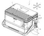
図1〜図6を参照し、印刷装置1を説明する。印刷装置1は、筒状の印刷媒体であるチューブ9を搬送しながら印刷し、且つ印刷後のチューブ9を切断する装置である。図1に示すように、印刷装置1は、本体ケース11及びカバー12を含む筐体10を備える。本体ケース11は、左右方向に長い直方体状の箱状部材である。カバー12は、本体ケース11の上側に配置された板状部材である。カバー12の後端部は、本体ケース11の後端部上側で回転可能に支持される。ロック機構13は、本体ケース11の前端部上側に設けられる。ロック機構13は、本体ケース11に対して閉じられたカバー12の前端部を係止して、カバー12の開放を規制する。(1. Description of the structure of the printing apparatus 1)
The
カバー12が本体ケース11に対して閉じられた場合(図1参照)、カバー12は装着面11A(図2参照)を覆う。装着面11Aは、本体ケース11の上面である。ユーザはカバー12を開く場合、ロック機構13を操作してカバー12の係止を解除し、カバー12をロック機構13から上側に回動させる。カバー12が本体ケース11に対して開かれた場合、装着面11Aは上方に露出する。 When the
カバー12の上面には、キーボード7が取り外し可能に装着される。キーボード7は、複数のキーを有する操作部7Aと、各種情報を含む画面を表示する表示部7Bを備える。ユーザは操作部7Aを操作することで、表示部7Bに表示される画面上で、チューブ9に印刷するキャラクタを編集できる。キャラクタは、文字、図形、及び記号等を含む。キーボード7内の基板(図示略)には、USB(Universal Serial Bus)ケーブル79が接続されている。USBケーブル79は、キーボード7の右側面から右方に引き出される。 A
筐体10の側面には、操作部17、チューブ挿入口15、及びチューブ排出口16(図2参照)が設けられる。操作部17は、本体ケース11の前面右側に設けられた、電源ボタン及びスタートボタンを含む複数の操作ボタンである。チューブ挿入口15は、本体ケース11の右面の後側上部に設けられた、チューブ9を筐体10の内部に案内するための開口である。チューブ排出口16は、本体ケース11の左面の後側上部に設けられた、チューブ9を筐体10の外部に排出するための開口である。チューブ排出口16は、チューブ挿入口15よりも若干前側にある。 An
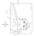
図2に示すように、装着面11Aには、リボン装着部30及びチューブ装着部40等が設けられる。リボン装着部30は、リボンカセット100を着脱可能な部位である。リボン装着部30は、平面視でリボンカセット100よりも若干大きい開口形状で形成された、上方に開口する凹部である。リボン装着部30の後部は、後述のチューブ装着部40と前後方向に連通している。本例のリボン装着部30は、装着面11Aの左部、且つチューブ装着部40の前側に設けられる。ユーザは、リボンカセット100の上下左右前後の各方向が、印刷装置1の上下左右前後の各方向と一致するように、リボンカセット100をリボン装着部30に上方から装着する。 As shown in FIG. 2, the mounting
リボン装着部30の内部には、位置決めピン31,32、支持ピン33,34、支持部35が設けられる。位置決めピン31,32及び支持ピン33,34は、何れもリボン装着部30の底面30Aから上方に延びる円柱状の軸体である。位置決めピン31,32及び支持ピン33,34の上端部は、何れも等しい上下方向位置(即ち、高さ位置)にある。位置決めピン31,32は、互いに同径である。支持ピン33,34は、互いに同径であり、且つ位置決めピン31,32よりも小径である。 Positioning pins 31 and 32, support pins 33 and 34, and a
位置決めピン31,32は、リボン装着部30に装着されたリボンカセット100の位置決め穴121,122(図9参照)と夫々対応する位置に設けられる。支持ピン33,34は、リボン装着部30に装着されたリボンカセット100のピン穴123,124(図9参照)と夫々対応する位置に設けられる。本例では、位置決めピン31及び支持ピン33は、後述の検出用回転軸71の右後側及び右前側に夫々設けられ、且つ互いに略前後方向に並ぶ。位置決めピン32及び支持ピン34は、後述のリボン巻取軸63の左前側及び左後側に夫々設けられ、且つ互いに略前後方向に並ぶ。位置決めピン32及び支持ピン34の前後方向距離は、位置決めピン31及び支持ピン33の前後方向距離よりも若干大きい。 The positioning pins 31 and 32 are provided at positions corresponding to the positioning holes 121 and 122 (see FIG. 9) of the
支持部35は、底面30Aから上方に突出する段差部である。支持部35の上端面は、位置決めピン31,32及び支持ピン33,34の各上端部と等しい上下方向位置(即ち、高さ位置)にある。支持部35は、リボン装着部30に装着されたリボンカセット100の前側凹部125(図9参照)と対応する位置に設けられる。本例では、支持部35は、印刷ヘッド61と前後方向に並ぶ位置、且つ位置決めピン32及び支持ピン33とを結ぶ線上に設けられる。支持部35の上端面は、平面視で前側凹部125に対応する形状の平面である。 The
チューブ装着部40は、チューブ9を着脱可能な部位である。チューブ装着部40は、チューブ挿入口15からチューブ排出口16の右側近傍まで延びる、上方に開口する溝部である。チューブ排出口16はチューブ挿入口15よりも若干前側にあるため、チューブ装着部40は若干左前側に傾いて略左右方向に延びる。チューブ挿入口15からチューブ排出口16に向けてチューブ装着部40が延びる方向を、チューブ搬送方向という。ユーザは、チューブ9がチューブ挿入口15からチューブ排出口16まで延びるように、チューブ9をチューブ搬送方向に沿ってチューブ装着部40に装着する。 The
図2〜図5を参照し、制御基板19、印刷機構60、搬送量検出部70、指標検出部80、及び切断機構90を説明する。図2に示すように、制御基板19は印刷装置1の動作制御を司る基板である。本例の制御基板19は、本体ケース11の内部における右後部に設けられ、且つUSB接続部18(図6参照)と接続する。USB接続部18は、筐体10(図1参照)の右面下部に形成されたプラグ収容部10A(図1参照)から、本体ケース11の外部に露出する。キーボード7から引き出されたUSBケーブル79(図1参照)は、プラグ収容部10Aを介してUSB接続部18に接続される。 The
印刷機構60は、印刷ヘッド61、可動搬送ローラ62、リボン巻取軸63、搬送モータ64(図6参照)等を含む。印刷ヘッド61及びリボン巻取軸63は、底面30Aから上方に向けて夫々立設される。印刷ヘッド61及びリボン巻取軸63は、位置決めピン31,32、支持ピン33,34、支持部35よりも上方まで延びる。 The
印刷ヘッド61は、発熱体(図示外)を備えるサーマルヘッドである。印刷ヘッド61は、リボン装着部30に装着されたリボンカセット100のヘッド挿入部109(図7参照)と対応する位置に設けられる。本例では、印刷ヘッド61はリボン装着部30の後部の略中央に設けられる。 The
リボン巻取軸63は、後述の巻取スプール300(図4参照)と共に回転可能な軸である。リボン巻取軸63の外周面には、リボン巻取軸63の軸線を中心として放射状且つ等間隔で配置された、複数の突出片63Aが設けられている(図4参照)。各突出片63Aは、リボン巻取軸63の外周面から半径方向外側に突出し、且つリボン巻取軸63の上端部近傍から下方に延びる。リボン巻取軸63は、リボン装着部30に装着されたリボンカセット100の第一支持孔111(図7参照)と対応する位置に設けられる。本例では、リボン巻取軸63は、リボン装着部30の左部において、支持ピン34よりも前側、且つ位置決めピン32よりも後側にある。 The ribbon take-up
可動搬送ローラ62は、印刷ヘッド61に相対して回転可能なローラである。可動搬送ローラ62は、リボン装着部30の後側に配置され、カバー12(図1参照)の開閉に伴って退避位置と作動位置とに変位可能である。可動搬送ローラ62が退避位置にある場合、可動搬送ローラ62はチューブ装着部40の後側に配置されて、印刷ヘッド61から離隔する(図2参照)。可動搬送ローラ62が作動位置にある場合、可動搬送ローラ62の一部はチューブ装着部40の内側に配置されて、印刷ヘッド61に近接する(図3参照)。 The
搬送モータ64は、可動搬送ローラ62及びリボン巻取軸63を回転駆動するモータである。図4に示すように、リボン巻取軸63の下端近傍には、リボン巻取軸63を中心として回転可能な円盤状のギア65が設けられる。ギア65は、ワンウェイクラッチ66を介して、リボン巻取軸63の周囲に固定された固定部材67と連結される。ワンウェイクラッチ66は、クラッチバネの弾性力によって、リボン巻取軸63を安定的に回転させると共に、リボン巻取軸63が所定の巻取り方向(本例では、平面視で反時計回り方向)とは反対方向(以下、逆転方向)に回転するのを規制する。 The
搬送モータ64は、ギア65を平面視で反時計回り方向に回転させることによって、ワンウェイクラッチ66及び固定部材67を介して、リボン巻取軸63を巻取り方向に回転させる。搬送モータ64がギア65を回転するのに伴って、ギア65と連動するギア群(図示外)を介して、可動搬送ローラ62(図2参照)が平面視で時計回り方向に回転する。これにより、可動搬送ローラ62及びリボン巻取軸63は同期して回転する。 The
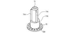
図4に示すように、搬送量検出部70は、印刷動作時におけるインクリボン8の搬送量を検出するための部材である。搬送量検出部70は、検出用回転軸71、検出板72、及びセンサ73を含む。検出用回転軸71は、底面30Aから上方に向けて立設される(図2参照)。検出用回転軸71は、位置決めピン31,32、支持ピン33,34、支持部35よりも上方まで延びる。検出用回転軸71の上端部は、印刷ヘッド61及びリボン巻取軸63の各上端部よりも下方にある。検出用回転軸71は、後述のリボンスプール200と共に回転可能な軸である。 As shown in FIG. 4, the carry
図2に示すように、検出用回転軸71は、リボン装着部30に装着されたリボンカセット100の第二支持孔112(図9参照)と対応する位置に設けられる。本例では、検出用回転軸71は、リボン装着部30の右部において、位置決めピン31よりも前側、且つ支持ピン33よりも後側にある。検出用回転軸71の軸線は、リボン巻取軸63の軸線よりも若干前側にある。 As shown in FIG. 2, the
図4及び図5に示すように、検出用回転軸71は、複数の突出片71A、円筒部71B、検出板72を有する。円筒部71Bは、検出用回転軸71の周囲に設けられ、且つ検出用回転軸71と共に回転可能な円筒状の部材である。複数の突出片71Aは、円筒部71Bの外周面に設けられ、且つ検出用回転軸71の軸線を中心として放射状且つ等間隔で配置される。各突出片71Aは、円筒部71Bの外周面から半径方向外側に突出し、且つ円筒部71Bの上端部近傍から下方に延びる。 As shown in FIGS. 4 and 5, the
検出板72は、円筒部71Bの下端近傍から半径方向外側に突出する円盤状である。検出板72の平面視中心は、検出用回転軸71の軸線と一致する。検出板72には、複数の検出孔72Aが設けられる。複数の検出孔72Aは、検出板72の平面視中心の周囲に放射状且つ等間隔で配置された、検出板72を上下方向に貫通する孔である。 The
センサ73は、発光部73A及び受光部73Bを有する透過型フォトセンサである。発光部73A及び受光部73Bは、検出板72を挟んだ上下両側に対向配置される。CPU41(図6参照)は印刷動作時に、発光部73Aから受光部73Bに向けて光を照射させる。発光部73Aから照射された光は、複数の検出孔72Aの何れかを通過すると、受光部73Bによって受光される。このときセンサ73は、ON信号をCPU41に出力する。一方、発光部73Aから照射された光は、検出板72で反射されると、受光部73Bによって受光されない。このときセンサ73は、OFF信号をCPU41に出力する。なお、センサ73は、検出板72で反射された光を検出可能な反射型フォトセンサでもよい。 The
図2に示すように、指標検出部80は、リボンカセット100の種類指標部190(図9参照)を検出するための部材である。指標検出部80は、図示外の基板上に設けられた五つの検出スイッチ81を有する。各検出スイッチ81は、上下方向に進退可能な機械式スイッチである。五つの検出スイッチ81は夫々、支持部35の上端面に形成された穴の内側で、上下方向に移動可能である。五つの検出スイッチ81は、リボン装着部30に装着されたリボンカセット100の指標部191〜195(図9参照)と対応する位置に設けられる。本例では、四つの検出スイッチ81が互いに左右方向に並んで配置される。これら四つの検出スイッチ81のうちで左から二番目の検出スイッチ81の後側に、残り一つの検出スイッチ81が配置される。 As shown in FIG. 2, the
各検出スイッチ81は、図示外のバネによって上方に付勢されている。外力が加えられていない検出スイッチ81は、図示外のバネの付勢力によって、支持部35から基準位置まで上方に移動する。指標検出部80は、基準位置にある検出スイッチ81に対応するOFF信号を、後述のCPU41(図6参照)に出力する。一方、上方から付勢された検出スイッチ81は、基準位置よりも下方にある押下位置まで移動する。指標検出部80は、押下位置にある検出スイッチ81に対応するON信号を、CPU41に出力する。五つの検出スイッチ81のON信号及びOFF信号の組み合わせを、種類検出パターンという。 Each
切断機構90は、チューブ9の切断動作を実行する機構である。切断機構90は、本体ケース11におけるチューブ装着部40の左端部近傍に設けられる。つまり切断機構90は、印刷ヘッド61よりもチューブ搬送方向の下流側にある。切断機構90は、受台91、切断刃92、及び切断モータ93(図6参照)を含む。受台91は、チューブ装着部40の左端部前側に設けられた直方体状である。切断刃92は、チューブ装着部40を挟んで、受台91に対して後側から対向する。切断モータ93は、切断刃92を前後方向に移動させることで、切断刃92を受台91に対して接近又は離隔させる。 The
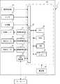
図6を参照し、印刷装置1の電気的構成を説明する。制御基板19は、CPU41、ROM42、RAM44、フラッシュメモリ45、及び入出力インターフェース49等を備え、これらがデータバスを介して接続される。ROM42は、CPU41が印刷動作を含む各種制御を実行するためのプログラムを記憶する。RAM44は、各種データを一時的に記憶する。フラッシュメモリ45は、種類検出パターンに対応するリボン種類を定めたテーブルを記憶する。例えばリボン種類は、リボンカセット100に収容されているインクリボン8の色及び幅である。 The electrical configuration of the
印刷装置1は、電源部48を有する。電源部48は、本体ケース11内に装着された電池(図示外)に接続され、又はコードを介して外部電源(図示外)に接続され、制御基板19に電源を供給する。操作部17、USB接続部18、駆動回路51〜53、センサ73、指標検出部80は、入出力インターフェース49に夫々接続される。USB接続部18は、USBケーブル79(図1参照)を介してキーボード7と接続する。CPU41は、操作部17を介して入力された各種情報を受付ける。CPU41は、操作部7A(図1参照)を介して入力された各種指示を受付け、且つ表示部7Bの画面を表示制御する。CPU41は、センサ73から出力されたON/OFF信号、及び指標検出部80から出力された種類検出パターンを受付ける。 The
駆動回路51〜53は、印刷ヘッド61、搬送モータ64、及び切断モータ93と夫々接続する。CPU41は、駆動回路51に制御信号を送信することによって、印刷ヘッド61を駆動制御する。CPU41は、駆動回路52にパルス信号を送信することによって、搬送モータ64を駆動制御する。CPU41は、駆動回路53に制御信号を送信することによって、切断モータ93を駆動制御する。 The
(2.リボンカセット100の構造説明)
図7〜図12を参照し、リボンカセット100を説明する。図7〜図10は、印刷動作に使用されていない初期状態のリボンカセット100を例示する。初期状態のリボンカセット100では、インクリボン8が全て未使用である。リボンスプール200には、予め定められた上限量のインクリボン8が巻かれている。巻取スプール300には、インクリボン8が巻かれていない(先述の図4も同様)。(2. Structure of ribbon cassette 100)
The
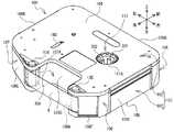
図7〜図9に示すように、リボンカセット100は、インクリボン8を収容するケース101を有する。ケース101の形状は、左右方向に長く且つ上下方向に短い箱状である。ケース101は、下ケース103と、下ケース103の上側に組み付けられる上ケース102とからなる。上ケース102の外面及び下ケース103の外面は夫々、ケース101の上面104及び下面105である。上面104及び下面105は、互いに上下方向に対向し、且つ平面視で略同形である。なお、ケース101の左右方向中心を通って前後方向に延びる仮想線は、中心線C1である。ケース101の前後方向中心を通って左右方向に延びる仮想線は、中心線C2である。 As shown in FIGS. 7 to 9, the
ケース101の側面106は、上面104と下面105とに亘って上下方向に延び、且つ上面104及び下面105の各外縁部に沿って延びる。側面106は、前面106A、右面106B、左面106C、ヘッド周面106D、及び接続面106E,106Fを含む。前面106Aは、左右方向に延びる。右面106B及び左面106Cは夫々、前面106Aの右端部及び左端部から平行に後方へ延びる。右面106B及び左面106Cは、互いに左右方向に並んで配置され、且つ各々の前後方向長さが略等しい。 The
ヘッド周面106Dは、側面106のうちで、平面視で中心線C1を跨いで設けられた、ケース101の後端側から前方に凹む部位である。接続面106Eは、ヘッド周面106Dの右後端部から右前方向に延び、右面106Bの後端部と接続する。接続面106Fは、ヘッド周面106Dの左後端部から左前方向に延び、左面106Cの後端部と接続する。接続面106Eの延伸方向長さは、接続面106Fの延伸方向長さよりも大きい。 The head
ヘッド周面106Dに囲まれた内側領域は、ヘッド挿入部109である。ヘッド挿入部109は、ケース101を上下方向に貫通し、且つケース101の後方に開口する。ヘッド挿入部109は、平面視で左右方向に長い略矩形状であり、且つ中心線C1を跨いで左右方向に延びる。ヘッド挿入部109の左右方向中心は、中心線C1よりも若干左側にある。 An inner region surrounded by the head
ケース101のうちでヘッド挿入部109の右側にある部位は、第一案内部107である。第一案内部107は、ヘッド周面106Dの右面と接続面106Eとで囲まれた、平面視で三角形状である。第一案内部107の左後端部には、ヘッド挿入部109と連通する開口であるリボン出口107Aが設けられる。インクリボン8は、リボン出口107Aを介してケース101内部から外部へと搬送される。ケース101のうちでヘッド挿入部109の左側にある部位は、第二案内部108である。第二案内部108は、ヘッド周面106Dの左面と接続面106Fとで囲まれた、平面視で三角形状である。第二案内部108の右後端部には、ヘッド挿入部109と連通する開口であるリボン入口108Aが設けられる。インクリボン8は、リボン入口108Aを介してケース101外部から内部へと搬送される。つまり、インクリボン8の一部は、リボン出口107Aとリボン入口108Aとの間で、ケース101から露出する。 A portion of the
ケース101には、巻取スプール300を回転支持する第一支持孔111と、リボンスプール200を回転支持する第二支持孔112(図9参照)とが設けられる。第一支持孔111は、ケース101の左部に設けられ、第二案内部108よりも前側、且つ後述の前側凹部125よりも後側にある。第一支持孔111は、上ケース102を上下方向に貫通する円孔である上孔111A(図8参照)と、下ケース103を上下方向に貫通する円孔である下孔111B(図9参照)とからなる。上孔111A及び下孔111Bは、互いに上下方向に並んで配置された同径の孔である。第一支持孔111で支持された巻取スプール300の回転中心を通る回転軸線を、軸線Jという。 The
第二支持孔112は、ケース101の右部に設けられ、第一案内部107よりも前側、且つ前側凹部125よりも後側にある。第二支持孔112は、下ケース103を上下方向に貫通する円孔である。第二支持孔112で支持されたリボンスプール200の回転中心を通る回転軸線を、軸線Pという。軸線P,Jは中心線C2よりも前側にある。軸線Pは軸線Jよりも前側にある。 The
図9に示すように、下ケース103には、位置決め穴121,122、ピン穴123,124、及び前側凹部125が設けられる。位置決め穴121,122、ピン穴123,124は、何れも下面105から上方に凹む凹部である。位置決め穴121,122及びピン穴123,124の各上端部は、ケース101において予め定められた上下方向位置である高さ基準位置にある。高さ基準位置は、ケース101の上下方向中心から規定距離だけ下方にある。規定距離は、ケース101の上下方向長さ(即ち、ケース101の厚み)に関わらず一定である。 As shown in FIG. 9, the
本例では、位置決め穴121及びピン穴123は、第二支持孔112の右後側及び右前側に夫々設けられ、且つ互いに略前後方向に並ぶ。位置決め穴121及びピン穴123は、何れも右面106Bの近傍にある。位置決め穴122及びピン穴124は、下孔111Bの左前側及び左後側に夫々設けられ、且つ互いに略前後方向に並ぶ。位置決め穴122及びピン穴124は、何れも左面106Cの近傍にある。位置決め穴122及びピン穴123は、中心線C2よりも後側にある。位置決め穴121及びピン穴124は、中心線C2よりも後側にある。位置決め穴122及びピン穴124の前後方向距離は、位置決め穴121及びピン穴123の前後方向距離よりも大きい。 In this example, the
位置決め穴121の下部は、円形の開口形状を有する。位置決め穴121の下部の開口幅は、位置決めピン31(図2参照)の軸径よりも若干大きい。位置決め穴121の上部である係止部121Aは、高さ基準位置にある天面(図示外)によって閉じられた、下方に開口する丸穴である。係止部121Aの開口幅は、位置決め穴121の下部よりも小径であって、位置決めピン31の軸径と同径である。 A lower portion of the
位置決め穴122の下部は、位置決め穴121の下部と同様に円形の開口形状を有する。位置決め穴122の下部の開口幅は、位置決めピン32(図2参照)の軸径よりも若干大きい。位置決め穴122の上部である係止部122Aは、高さ基準位置にある天面(図示外)によって閉じられた、下方に開口する穴である。係止部122Aは、右後方向及び左前方向に延びる長穴である。係止部122Aの最小開口幅(即ち、係止部122Aの短手方向長さ)は、位置決めピン32の軸径と同径である。係止部122Aの長手方向の延長線上に、係止部121Aが配置されている。係止部121A,122Aの各中心を結ぶ仮想直線は、連結線C3である。連結線C3は、係止部122Aの長手方向と略平行に延びる。軸線Jは連結線C3よりも左側にある。軸線Pは連結線C3よりも右側にある。 The lower portion of the
ピン穴123,124は、各々の上端部が高さ基準位置にある天面(図示外)によって閉じられた、下方に開口する丸穴である。ピン穴123,124の開口幅は夫々、支持ピン33,34の軸径よりも若干大きい。ピン穴123,124の開口幅は、互いに同径であり、且つ位置決め穴121,122の各下部の開口幅よりも小さい。 Each of the pin holes 123 and 124 is a round hole that opens downward and is closed by a top surface (not shown) having an upper end portion at a height reference position. The opening widths of the pin holes 123 and 124 are slightly larger than the shaft diameters of the support pins 33 and 34, respectively. The opening widths of the pin holes 123 and 124 have the same diameter and are smaller than the opening widths of the lower portions of the positioning holes 121 and 122.
前側凹部125は、下面105から上方に凹む段差部である。前側凹部125の上端面は、高さ基準位置にある。本例の支持部35は、ヘッド挿入部109と前後方向に並ぶ位置、且つ位置決め穴122及びピン穴123とを結ぶ線上にある。詳細には、前側凹部125は、下ケース103の前端部に設けられ、中心線C1を跨いで左右方向に延びる。前側凹部125の左端部は、左右方向において、ヘッド挿入部109の左端部と略等しい位置にある。前側凹部125の右端部は、左右方向において、ヘッド挿入部109の右端部よりも若干右側にある。前側凹部125の左右方向中心は、中心線C1よりも若干左側にある。前側凹部125は、底面視で中心線C1に沿って後方に延びる。前側凹部125の後端部は、前後方向において、ピン穴123と略等しい位置にある。 The front
前側凹部125の上端面には、リボン種類を示す種類指標部190が設けられる。軸線J,Pと交差する仮想直線は、連結線C4である。種類指標部190は、連結線C4よりも前側にあり、且つヘッド周面106Dと前後方向に並ぶ。本例の種類指標部190は、五つの指標部191〜195を含む。指標部191〜194は、前面106Aに沿って左右方向に並んで配置される。指標部195は、指標部191〜194のうちで左から二番目の指標部193の後側に配置される。各指標部191〜195は、リボンカセット100のリボン種類に応じたパターンで、面部又は孔部の何れかで構成される。本例では、指標部191〜193,195が孔部、指標部194が面部である。 A
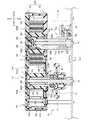
図5及び図10に示すように、インクリボン8は、その幅方向(短手方向)が上下方向と略平行となる姿勢で、ケース101内に収容される。ケース101の内部には、リボンスプール200及び巻取スプール300が設けられる。インクリボン8は、その幅方向が上下方向と略平行となる姿勢で、所定の搬送経路(以下、リボン搬送経路)を経由してリボンスプール200から巻取スプール300まで搬送される。リボン搬送経路に沿ってインクリボン8が搬送される方向を、リボン搬送方向という。リボンスプール200は、上下方向に延びる円筒状の部材であって、インクリボン8の長手方向の一端側(即ち、リボン搬送方向の上流側)が巻かれる。巻取スプール300は、上下方向に延びる円筒状の部材であって、インクリボン8の長手方向の他端側(即ち、リボン搬送方向の下流側)が連結される。 As shown in FIGS. 5 and 10, the
リボンスプール200の内部には、上下方向に貫通する装着孔200Aが設けられる。リボンスプール200の外周面は、未使用のインクリボン8が巻かれる供給面200Bである。詳細には、インクリボン8が有する両面のうちでインクが塗布されたインク面が内側となるように、供給面200Bに未使用のインクリボン8が巻かれる。リボンスプール200では、上限量のインクリボン8を供給面200Bに巻くことができる。以下の説明では、供給面200Bに巻かれた状態のインクリボン8を、第一リボンロール8Aという。第一リボンロール8Aの外径は、供給面200Bに上限量のインクリボン8が巻かれた状態で最大値となる。リボンスプール200に巻かれた上限量のインクリボン8を、最大径の第一リボンロール8Aという。 Inside the
リボンスプール200の上端部及び下端部には、突出部200C,200Dが夫々設けられる。突出部200Cは、供給面200Bよりも上方に突出する。突出部200Dは、供給面200Bよりも下方に突出する。上ケース102の内面102Aには、第二支持孔112と上下方向に対向する支持部140が設けられる(図11参照)。突出部200Cは、支持部140に下方から装着されて、支持部140によって回転支持される。突出部200Dは、第二支持孔112に上方から嵌め込まれて、第二支持孔112によって回転支持される。即ちリボンスプール200は、第二支持孔112及び支持部140によって回転自在に支持される。従って軸線Pは、平面視で第二支持孔112の中心と略一致する。 Protruding
装着孔200Aの上部には、クラッチバネ280が巻回された円筒状の回転部材290が装着される。クラッチバネ280の端部は、支持部140に係止される。回転部材290は、リボンスプール200と共に回転可能である。リボンスプール200が所定の引出し方向(本例では、平面視で時計回り方向、図10の矢印R3参照)に回転する場合、クラッチバネ280が拡径されるため、回転部材290を介してリボンスプール200に付与される回転負荷は相対的に小さい。回転負荷は、部材の回転を妨げるように作用する負荷である。回転負荷は、リボンスプール200に回転トルクを付与する。回転トルクは、第一リボンロール8Aの外径の大小によって変化せず、安定して発生する。 A cylindrical rotating
一方、リボンスプール200が引出し方向とは反対方向(図10の矢印R4参照)に回転する場合、クラッチバネ280が縮径されるため、回転部材290を介してリボンスプール200に付与される回転負荷は相対的に大きい。つまり回転部材290は、クラッチバネ280の弾性力によって、リボンスプール200を引出し方向に安定的に回転させると共に、リボンスプール200が引出し方向とは反対方向に回転するのを規制する。 On the other hand, when the
巻取スプール300は、本体部301、複数の係合突起302、上支持板303、下支持板304等を有する。本体部301は、上下方向に延びる円筒体である。本体部301の内部には、上下方向に貫通する装着孔300Aが設けられる。複数の係合突起302は夫々、本体部301の内周面から軸線Jに向けて突出する。複数の係合突起302は、軸線Jを中心として放射状且つ等間隔で配置されている。 The take-up
本体部301の外周面は、使用済みのインクリボン8が巻かれる巻取面300Bである。詳細には、インクリボン8が有する両面のうちでインク面が外側となるように、巻取り方向(矢印R1方向)に沿って巻取面300Bに使用済みのインクリボン8が巻かれる。巻取スプール300では、上限量のインクリボン8を巻取面300Bに巻くことができる。以下の説明では、巻取面300Bに巻かれた状態のインクリボン8を、第二リボンロール8Bという(図3参照)。第二リボンロール8Bの外径は、巻取面300Bに上限量のインクリボン8が巻かれた状態で最大値となる。巻取スプール300に巻かれた上限量のインクリボン8を、最大径の第二リボンロール8Bという。 The outer peripheral surface of the
上支持板303は、本体部301の上端近傍から半径方向外側に延びる円盤状である。下支持板304は、本体部301の下端近傍から半径方向外側に延びる円盤状である。上支持板303及び下支持板304は、上下方向に対向配置された同径の板状部材である。上支持板303と下支持板304との上下方向距離は、インクリボン8の幅方向長さよりも若干大きい。これにより、第二リボンロール8Bは、上支持板303と下支持板304との間で保持される。上支持板303と下支持板304と巻取面300Bとで囲まれた領域は、第二リボンロール8Bを収容可能な収容部305である。収容部305の外径(即ち、上支持板303及び下支持板304の夫々の外径)は、最大径の第二リボンロール8Bの外径よりも大きい。 The
本例では、上支持板303は、供給面200Bよりも上側にある。下支持板304は、供給面200Bよりも下側にある。上支持板303及び下支持板304の各右端部は、中心線C1とリボンスプール200との間にある。つまり、収容部305は供給面200Bに対して左側から近接する。所定量以上のインクリボン8が供給面200Bに巻かれている場合、第一リボンロール8Aの一部が収容部305に右側から進入する。換言すると、第一リボンロール8Aの半径が軸線Pから収容部305までの距離を超える場合、第一リボンロール8Aの一部が収容部305内に配置される。 In this example, the
このように、第一リボンロール8Aの外径が所定長さよりも大きい場合には、第一リボンロール8Aの一部が収容部305に収容される。リボンスプール200と巻取スプール300とをより近い位置に配置できるため、ケース101をより小型化できる。なお、インクリボン8の搬送に伴って、第二リボンロール8Bの外径が増加すると共に、第一リボンロール8Aの外径は減少する。そのため、第一リボンロール8A及び第二リボンロール8Bが互いに干渉することを抑制できる。 Thus, when the outer diameter of the
巻取スプール300の上端部及び下端部には、突出部300C,300Dが夫々設けられる。突出部300Cは、上支持板303よりも上方に突出する。突出部300Dは、下支持板304よりも下方に突出する。突出部300Cは、上孔111Aに下方から嵌め込まれて、上孔111Aによって回転支持される。突出部300Dは、下孔111Bに上方から嵌め込まれて、下孔111Bによって回転支持される。即ち巻取スプール300は、第一支持孔111によって回転自在に支持される。従って軸線Jは、平面視で第一支持孔111の中心と略一致する。 Protruding
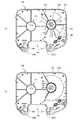
図10及び図12に示すように、下支持板304の下側には、金属製のクラッチバネ310が設けられる。クラッチバネ310は、弛んだ状態のインクリボン8を適切なテンションが付与されている状態に戻すためのバネ部材である。クラッチバネ310は、コイル状の巻付部311と、巻付部311の上端部311Aから延設された延設部312とを有する。 As shown in FIGS. 10 and 12, a metal
巻付部311は、巻付部311の上端部311Aから巻付部311の下端部311Bまで巻取り方向とは相対的に反対の方向(即ち、逆転方向、矢印R2方向)に延び、且つ突出部300Dの外周面に複数周(本例では、3周)巻かれる。上端部311Aは、下支持板304の下面304Aと接触する。下端部311Bは上端部311Aよりも下側(即ち、下支持板304から離隔する方向)に位置する。延設部312は、上端部311Aから下支持板304に沿って接線方向に、ヘッド周面106Dの近傍(即ち、平面視で後述の係合部150よりも軸線Jから離隔する位置)まで直線状に延びる。延設部312のうち上端部311Aから下支持板304の外径縁よりも内側の部位は、下面304Aと接触する。延設部312の先端部312A近傍はケース101に設けられた後述の係合部150に係合する。延設部312は、先端部312Aから上端部311Aに対して軸線Jとは反対の方向に延びる係止部313を有する。係止部313は、クラッチバネ310が後述の係合部150から延設部312の延びる方向に外れることを抑制する。 The winding
巻取スプール300が巻取り方向(矢印R1方向)に回転する場合、巻付部311が拡径されるため、巻取スプール300に付与される回転負荷は相対的に小さい。一方、巻取スプール300が逆転方向に回転する場合、巻付部311が縮径されるため、巻取スプール300に付与される回転負荷は相対的に大きい。つまり、クラッチバネ310は、弾性力によって、巻取スプール300を巻取り方向に安定的に回転させると共に、巻取スプール300がし逆転方向に回転するのを規制する。 When the take-up
図10に示すように、ケース101の内部には、係合部150及び複数の屈曲部131〜137が設けられる。係合部150は、クラッチバネ310の巻取り方向及び逆転方向への移動を規制するための部材である。係合部150は、平面視で中心線C1とヘッド周面106Dとの近傍に設けられる。即ち、係合部150は、平面視で軸線Jと軸線Pとの間、且つ連結線C4よりも後方に設けられる。上端部311Aから係合部150までの距離は、上端部311Aから先端部312Aまでの長さよりも小さく、且つ先端部312Aから係合部150までの距離よりも大きい。即ち、係合部150は、平面視で上端部311Aと先端部312Aとの間のうち、先端部312Aに近い位置に設けられる。軸線Pから係合部150までの距離は、最大径の第一リボンロール8Aの半径よりも大きい。即ち、係合部150は、平面視で最大径の第二リボンロール8Bの最外周よりも軸線Jから離隔する位置に設けられる。軸線Jから係合部150までの距離は、最大径の第二リボンロール8Bの半径よりも大きい。即ち、係合部150は、平面視で最大径の第二リボンロール8Bの最外周よりも軸線Pから離隔する位置に設けられる。係合部150は、第一係合部151と第二係合部152とを有する。 As shown in FIG. 10, an
第一係合部151は、ヘッド周面106Dの近傍、且つ中心線C1の若干左側で下ケース103の内面103Aに立設される。第一係合部151は、右前方及び上方に延びる板状部材である。第二係合部152は、第一係合部151から右前方に若干離隔した位置で内面103Aに立設される。第二係合部152は、右前方及び上方に延びる板状部材である。第一係合部151と第二係合部152とは、延設部312を挟んで互いに対向する。以下、第一係合部151及び第二係合部152おける互いに対向する面を、夫々、第一対向面151A及び第二対向面152Aという。 The
第一係合部151は、延設部312が第一対向面151Aに接触することにより、巻取り方向への延設部312の移動を規制する。一方、第二係合部152は、延設部312が第二対向面152Aに接触することにより、逆転方向への延設部312の移動を規制する。 The first
屈曲部131〜137は、リボン搬送経路を設定するための部材であり、且つリボン搬送経路を蛇行させるための部材である。各屈曲部131〜137は、内面103Aに立設され、上ケース102まで上方に延びる。屈曲部131,132,136は、下ケース103に固定された円柱体である。詳細には、屈曲部131,132,136は、下ケース103と一体に形成されている。屈曲部133〜135,137は、上下方向に延びる軸を中心に回転可能な円筒状の回転体である。 The
屈曲部131〜134は、ケース101の右後部に設けられる。屈曲部131は、平面視で、第二支持孔112(図9参照)の右後側にある。位置決め穴121は、前後方向において屈曲部131とリボンスプール200との間にある。屈曲部131は、左右方向において位置決め穴121とリボンスプール200との間にある。屈曲部131は、前後方向においてヘッド周面106Dとリボンスプール200との間にある。軸線Pから屈曲部131までの距離は、最大径の第一リボンロール8Aの半径よりも大きい。屈曲部132〜134は、第一案内部107にある。屈曲部132は、屈曲部131の左後側にある。屈曲部133は、屈曲部132の左側にある。屈曲部134は、屈曲部133の左後側にあり、且つ第一案内部107の左後部にある。 The
屈曲部135〜137は、ケース101の左後部に設けられる。屈曲部135〜137は、第一案内部107にある。屈曲部137は、第一支持孔111(図8参照)の左後側にある。軸線Jから屈曲部137までの距離は、最大径の第二リボンロール8B(図3参照)の半径よりも大きい。屈曲部136は、屈曲部137の左後側にある。屈曲部135は、屈曲部136の右後側にあり、且つ第二案内部108の右後部にある。 The
図8及び図11に示すように、上ケース102における支持部140の周囲には、窓部160及び少なくとも一つの弾性体180が設けられる。窓部160は、上ケース102を上下方向に貫通し、且つ支持部140を中心として半径方向に延びる長穴である。本例の窓部160は、支持部140の後側から後方に延びる。窓部160の後端部は、平面視で最大径の第一リボンロール8Aの外側にある。ユーザは、窓部160を介して第一リボンロール8Aの外径位置を目視することで、未使用のインクリボン8の残量を認識できる。 As shown in FIGS. 8 and 11, a
各弾性体180は、内面102Aに設けられた板状スポンジである。各弾性体180は、支持部140を中心として半径方向に延びる。各弾性体180は、平面視で、支持部140の外縁から最大径の第一リボンロール8Aの外側まで延びる。図4に示すように、各弾性体180はケース101の内部において、第一リボンロール8Aに対して上方から弾性接触する。即ち各弾性体180、第一リボンロール8Aの上面における半径方向全体に亘って面接触して、第一リボンロール8Aを下方に付勢する。本例では、二つの弾性体180が、支持部140の前側及び右前側に配置される。各弾性体180は、何れも4mm厚の扇形をなす同一の板状スポンジであり、図示外の両面テープによって内面102Aに貼り付けられる。各弾性体180が第一リボンロール8Aに弾性接触した状態で、各弾性体180の厚みは2mm程度である。 Each
(3.印刷装置1及びリボンカセット100の動作態様)
図2〜図4、図9、及び図10を参照し、印刷装置1及びリボンカセット100の動作態様を説明する。印刷装置1では、カバー12が開かれるのに伴って、可動搬送ローラ62は退避位置に変位する。リボン装着部30にリボンカセット100が装着されると、印刷ヘッド61はヘッド挿入部109に挿入される。リボン巻取軸63は下孔111Bを介して、巻取スプール300の装着孔300Aに挿入される。複数の突出片63Aは、複数の係合突起302に係合される。検出用回転軸71は第二支持孔112を介して、リボンスプール200の装着孔200Aに挿入される。複数の突出片71Aは、複数の突出片63Aと同様に、装着孔200A内でリボンスプール200に係合される。(3. Operational aspects of the
The operation modes of the
リボン装着部30に装着されるリボンカセット100は、以下のようにリボン装着部30における適正な位置に位置決めされる。位置決めピン31,32及び支持ピン33,34は、位置決め穴121,122及びピン穴123,124に夫々挿入される。支持ピン33の上端部は、ピン穴123の天面に接触して、リボンカセット100の上下方向を位置決めする。支持ピン34の上端部は、ピン穴124の天面に接触して、リボンカセット100の上下方向を位置決めする。位置決めピン31の上端部は、係止部121Aに緊密に嵌め込まれて、リボンカセット100の上下左右前後の各方向を位置決めする。位置決めピン32の上端部は、係止部122Aに緊密に嵌め込まれて、リボンカセット100の上下左右前後の各方向を位置決めする。支持部35は前側凹部125を下方から支持して、リボンカセット100の上下方向を位置決めする。 The
前側凹部125が支持部35によって支持されると、五つの検出スイッチ81が種類指標部190によって選択的に押圧される。本例では、各指標部191〜195が、五つの検出スイッチ81の何れかと夫々対向する。指標部191〜193,195と対向する各検出スイッチ81は、孔部内に挿入されて基準位置に保持される。指標部194と対向する検出スイッチ81は、面部で付勢されて押下位置に変位する。 When the front
指標検出部80は、基準位置の各検出スイッチ81に対応するOFF信号と、押下位置の検出スイッチ81に対応するON信号との組み合わせを、種類検出パターンとしてCPU41(図6参照)に出力する。CPU41は、受付けた種類検出パターンに対応するリボン種類を、フラッシュメモリ45(図6参照)のテーブルを参照して特定する。これにより印刷装置1は、リボン装着部30に装着されたリボンカセット100のリボン種類を特定できる。 The
リボンカセット100がリボン装着部30に装着され、且つチューブ9がチューブ装着部40に装着された状態で、カバー12が閉じられる。カバー12が閉じられると、可動搬送ローラ62は作動位置に変位する。可動搬送ローラ62は、チューブ装着部40にあるチューブ9と未使用のインクリボン8とを重ねて、印刷ヘッド61に向けて付勢する。このときチューブ9は、可動搬送ローラ62の付勢力によって弾性変形して、インクリボン8を介して印刷ヘッド61と面接触する。 The
CPU41は、キーボード7又は操作部17を介して印字開始指示が入力されると、搬送モータ64を駆動して可動搬送ローラ62及びリボン巻取軸63を回転させる。チューブ装着部40内にあるチューブ9は、可動搬送ローラ62の回転に伴って、チューブ搬送方向の下流側に搬送される。このとき、筐体10の外部にある印刷前のチューブ9は、チューブ挿入口15を介してチューブ装着部40内に引き込まれる。 When a print start instruction is input via the
リボン巻取軸63の回転に伴って、巻取スプール300が巻取り方向(矢印R1方向)に回転する。この場合、巻付部311は拡径される。巻取スプール300の回転に伴って、リボンスプール200が引出し方向(矢印R3方向)に回転する。これによりインクリボン8は、第一リボンロール8Aの後端近傍から引き出され、以下のリボン搬送経路に沿って搬送される。先述したように、リボンスプール200が引出し方向に回転する場合、クラッチバネ280の弾性力によって、リボンスプール200に相対的に小さい回転負荷が付与される。これにより、搬送されるインクリボン8に適度なテンションが付与されるため、インクリボン8の弛みが生じにくい。 As the
未使用のインクリボン8は、第一リボンロール8Aから引き出されたのち、屈曲部131の右前面側、屈曲部132の右後面側、屈曲部133の左前面側、屈曲部134の右後面側を順に経由する。次いで未使用のインクリボン8は、リボン出口107Aからケース101の外部に排出され、ヘッド挿入部109内を左方向に進む。このとき未使用のインクリボン8は、チューブ9と印刷ヘッド61との間を通る。 After the
CPU41は印刷ヘッド61を駆動して、チューブ9と印刷ヘッド61との間を通るインクリボン8を加熱して、チューブ9にキャラクタを印刷する。本例の印刷ヘッド61は、その後側を経由するチューブ9の前部にキャラクタを正像印刷する。その後、CPU41は切断モータ93を駆動して、切断刃92を受台91に対して接近させることで、印刷済みのチューブ9を切断する。切断されたチューブ9は、チューブ排出口16を介して筐体10の外部に排出される。 The
使用済みのインクリボン8は、リボン入口108Aからケース101の内部に進入して、屈曲部135の左後面側、屈曲部136の左面側、屈曲部137の右後面側を経由する。最後に、使用済みのインクリボン8は、巻取スプール300の左側から巻き取られ、第二リボンロール8Bとして保持される。このように、インクリボン8は、複数の屈曲部131〜137を経由することで、蛇行したリボン搬送経路に沿って搬送される。この場合、搬送されるインクリボン8と複数の屈曲部131〜137の夫々との間に摺動摩擦が生じる。リボン搬送経路に沿って搬送されるインクリボン8に、適度な搬送負荷が付与される。搬送負荷は、インクリボン8の搬送を妨げるように作用する負荷である。搬送されるインクリボン8に適度なテンションが付与されるため、インクリボン8の弛みが更に生じにくい。 The used
二つの弾性体180は、第一リボンロール8Aに対して軸線P方向に弾性接触する。未使用のインクリボン8が第一リボンロール8Aから引き出される場合、回転する第一リボンロール8Aと各弾性体180との間に摺動摩擦が生じる。この摺動摩擦によって、第一リボンロール8Aに適度な回転負荷が付与される。第一リボンロール8Aから引き出されるインクリボン8に、適度な搬送負荷が付与される。搬送されるインクリボン8に適度なテンションが付与されるため、インクリボン8の弛みが更に生じにくい。 The two
本例では、二つの弾性体180は、平面視で上支持板303(図4及び図10参照)と重複しない位置に設けられる。これにより、巻取スプール300及び各弾性体180が互いに干渉することを防止できる。二つの弾性体180は、窓部160とは異なる位置に設けられる。これにより、窓部160が各弾性体180によって塞がれることを防止できる。二つの弾性体180は、第一リボンロール8Aの互いに異なる周方向位置に弾性接触する。これにより、弾性体180が第一リボンロール8Aの一部分に偏って弾性接触する場合と比べて、第一リボンロール8Aの全体に適度な回転負荷を付与できる。二つの弾性体180は互いに同一部材であるため、各弾性体180の製造が容易である。 In this example, the two
第一リボンロール8Aの外径が最も小さい状態である場合に、弾性体180が第一リボンロール8Aに弾性接触すると、第一リボンロール8Aが幅方向に撓むおそれがある。本例では、二つの弾性体180は、第一リボンロール8Aの外径が最も小さい状態で、リボンスプール200と屈曲部131との間にあるインクリボン8とは異なる位置にある。第一リボンロール8Aの外径が最も小さい状態である場合、各弾性体180は第一リボンロール8Aと接触しない。これにより、第一リボンロール8Aから引き出されるインクリボン8が各弾性体180の弾性力で幅方向に撓むことを抑制できる。 When the outer diameter of the
なお、リボンスプール200の回転に伴って、検出用回転軸71も引出し方向に回転する。このときセンサ73は、発光部73Aの照射光が受光部73Bによって断続的に検出されることに応じて、ON信号及びOFF信号をCPU41に出力する。CPU41は、入力されたON/OFF信号に基づいて、印刷動作中における検出用回転軸71の回転量に相当するインクリボン8の搬送量を特定する。即ち印刷装置1は、印刷動作の開始時から起算したインクリボン8の使用量を特定できる。 As the
(4.引出し負荷)
インクリボン8が引き出される際の引出し負荷を説明する。引出し負荷は、ケース101内部から外部へのインクリボン8の引き出しを妨げるように作用する負荷である。リボン出口107Aを介してリボンスプール200側からインクリボン8が引き出される際には、インクリボン8に第一引出し負荷が付与される。第一引出し負荷は、リボン出口107Aよりもリボン搬送方向の上流側において、インクリボン8に付与される引出し負荷の総和である。具体的には、本例における第一引出し負荷は、リボン出口107Aよりもリボン搬送方向の上流側に設けられた複数の屈曲部131〜134とインクリボン8との間に生じた摺動摩擦による引出し負荷、クラッチバネ280の弾性力によってリボンスプール200に付与される回転負荷による引出し負荷、第一リボンロール8Aと各弾性体180との間に生じた摺動摩擦による引出し負荷等の和である。より詳細には、第一引出し負荷は、前記した引出し負荷に加え、リボンスプール200とケース101との間に生じる摺動摩擦による引出し負荷、第一リボンロール8Aにおいてインクリボン8同士の間に生じる摺動摩擦による引出し負荷、第一リボンロール8Aと内面103Aとの間に生じる摺動摩擦による引出し負荷等を含む。(4. Drawer load)
The drawing load when the
一方、リボン入口108Aを介して巻取スプール300側からインクリボン8が引き出される際には、インクリボン8に第二引出し負荷が付与される。第二引出し負荷は、リボン入口108Aよりもリボン搬送方向の下流側において、インクリボン8に付与される引出し負荷の総和である。具体的には、本例における第二引出し負荷は、リボン入口108Aよりもリボン搬送方向の下流側に設けられた複数の屈曲部135〜137とインクリボン8との間に生じる摺動摩擦による引出し負荷、クラッチバネ310の弾性力によって巻取スプール300に付与される回転負荷による引出し負荷等の和である。より詳細には、第二引出し負荷は、前記した引出し負荷に加え、巻取スプール300とケース101との間に生じる摺動摩擦による引出し負荷、第二リボンロール8Bと上支持板303又は下支持板304との間に生じる摺動摩擦による引出し負荷、第二リボンロール8Bにおいてインクリボン8同士の間に生じる摺動摩擦による引出し負荷等を含む。 On the other hand, when the
リボンカセット100では、第二引出し負荷が第一引出し負荷よりも小さくなるように、クラッチバネ310の材質、延設部312の長さ、巻付部311の巻き数、径等が選定され、且つ第二係合部152の設けられる位置(即ち、第二係合部152と上端部311Aとの間の距離)が決められている。これにより、例えばケース101から露出しているリボン出口107Aとリボン入口108Aとの間のインクリボン8のインク面に対して垂直方向に外力が付与された場合、インクリボン8は、リボン入口108Aを介して巻取スプール300側から引き出される。つまり、インクリボン8は、未使用のインクリボン8である第一リボンロール8Aからでなく、使用済みのインクリボン8である第二リボンロール8Bから引き出される。 In the
(5.クラッチバネ310の動作態様)
図10及び図13を参照し、クラッチバネ310の動作態様の詳細を説明する。例えば印刷動作時等、巻取スプール300に対して巻取り方向(矢印R1方向)に回転させる外力が付与された場合、巻取スプール300の回転に伴い、クラッチバネ310が巻取り方向に回転する。クラッチバネ310が巻取り方向に回転すると、延設部312が第一対向面151Aに接触し、巻取り方向への移動が規制される。これにより、巻付部311が拡径される。従って、巻取スプール300には相対的に小さな回転負荷しか付与されないため、巻取スプール300は安定的に巻取り方向に回転する。なお、巻取スプール300の巻取り方向への回転が終了した場合、拡径されていた巻付部311は拡径される前の状態(図10参照)に戻る。(5. Mode of operation of clutch spring 310)
With reference to FIG.10 and FIG.13, the detail of the operation | movement aspect of the
また、図13に示すように、例えばインクリボン8に対して後方から所定の大きさの外力Fが付与された場合、巻取スプール300に対して逆転方向(矢印R2方向)に回転させる外力が付与され、且つ、リボンスプール200に対して引出し方向(矢印R3方向)に回転させる外力が付与される。この場合、第二引出し負荷は第一引出し負荷よりも小さいため、巻取スプール300が逆転方向に回転する。巻取スプール300の逆転方向への回転に伴い、クラッチバネ310が逆転方向に回転する。 As shown in FIG. 13, for example, when an external force F having a predetermined magnitude is applied to the
クラッチバネ310が逆転方向に回転すると、延設部312が第二対向面152Aに接触し、逆転方向への移動が規制される。これにより、巻付部311が縮径されながら、延設部312が第二対向面152Aとの接触部を支点として弾性変形する。つまり、延設部312のうち上端部311A近傍の部分が突出部300Dの外周面に巻き込まれる。これに伴って、平面視で第二係合部152から離隔する位置にあった係止部313は、第二係合部152に接触する位置まで移動する。つまり、係止部313は、延設部312が突出部300Dの外周面に巻き込まれることにより、係合部150よりも軸線Jから離隔する位置において、係合部150から離隔する位置と係合部150に接触する位置との間で移動可能である。これにより、巻取スプール300は、延設部312が弾性変形した分だけ逆転方向に回転する。なお、外力Fが所定の大きさよりも小さい場合、係止部313は第二係合部152に接近するだけで、接触しない場合もある。 When the
以上のように、外力Fが付与されたインクリボン8は、巻取スプール300が逆転方向に回転することにより、リボン入口108Aを介して第二リボンロール8B側から引き出され、弛んだ状態となる。つまり、インクリボン8は、クラッチバネ310が弾性変形した分だけ弛む。ここで、インクリボン8が外力Fから解放された場合、弾性変形していたクラッチバネ310(図13参照)が弾性変形する前の形状(図10参照)に戻る。これにより、巻取スプール300は、巻取り方向に回転する。従って、弛んだ状態のインクリボン8(図13参照)は、適切なテンションが付与されている状態(図10参照)に戻される。 As described above, the
以上説明したように、本実施形態において、巻付部311は、延設部312が延設されている上端部311Aから、巻取り方向(矢印R1方向)とは相対的に反対の方向(矢印R2方向)に、巻取スプール300の突出部300Dの外周面に巻かれている。これにより、巻付部311は、巻取スプール300が巻取り方向に回転した場合に拡径され、巻取スプール300が逆転方向に回転した場合に縮径される。 As described above, in the present embodiment, the winding
例えば、ケース101から露出しているリボン出口107Aとリボン入口108Aとの間のインクリボン8のインク面に対して垂直方向に所定の大きさの外力(例えば外力F)が付与された場合、第二引出し負荷は第一引出し負荷よりも小さいため、巻取スプール300が逆転方向に回転する。この場合、巻取スプール300の逆転方向への回転に伴い、クラッチバネ310が逆転方向に回転する。 For example, when a predetermined external force (for example, external force F) is applied in a direction perpendicular to the ink surface of the
クラッチバネ310が逆転方向に回転すると、延設部312が第二対向面152Aに接触し、逆転方向への移動が規制される。これにより、巻付部311が縮径され、延設部312が係合部150との接触部を支点として弾性変形する。すなわち、巻取スプール300は、延設部312が弾性変形した分だけ逆転方向に回転する。故に、インクリボン8は、所定の大きさの外力によって、未使用のインクリボン8である第一リボンロール8Aからでなく、使用済みのインクリボン8である第二リボンロール8Bから引き出されて弛んだ状態になる。従って、リボンカセット100は、所定の大きさの外力によって未使用のインクリボン8が引き出されて無駄になることを抑制できる。 When the
そして、インクリボン8が所定の大きさの外力から解放された場合、弾性変形していた延設部312が弾性力によって元の状態へ戻り、巻付部311が拡径される。これにより、巻取スプール300が巻取り方向に回転して弛んだ状態であったインクリボン8を巻き取るため、インクリボン8は適正なテンションが付与されている状態に戻る。従って、リボンカセット100は、弛んだ状態のインクリボン8を適正なテンションが付与されている状態に戻すことができる。 When the
係合部150は、最大径の第二リボンロール8Bの最外周よりも巻取スプール300の軸線Jから離隔する位置に設けられる。従って、リボンカセット100は、第二リボンロール8Bと係合部150とが互いに干渉することを抑制できる。更に、上端部311Aと係合部150との間の距離を大きくできるため、延設部312の長さを長くできる。延設部312は、長さが長い方が弾性変形しやすい。従って、リボンカセット100は、延設部312の長さが短い場合に比べ、より大きく弛んだ状態のインクリボン8を適正なテンションが付与されている状態に戻すことができる。 The engaging
延設部312は、巻付部311の上端部311Aから接線方向に延設されている。これにより、延設部312が上端部311Aから曲げられて延設されている場合に比べ、上端部311Aへの負荷が小さい。故に、弾性変形したクラッチバネ310は、元の形状である延設部312が巻付部311の上端部311Aから接線方向に延設されている形状に弾性力によって戻りやすい。従って、リボンカセット100は、繰り返し使用によるクラッチバネ310の変形を抑制できる。 The extending
巻取スプール300は、上面で第二リボンロール8Bを保持する下支持板304を備える。下支持板304の外径は、最大径の第二リボンロール8Bの外径よりも大きい。延設部312は、第二リボンロール8Bとは反対側で下支持板304に沿って延びる。これにより、下支持板304は、クラッチバネ310がインクリボン8に接触し、巻取スプール300によるインクリボン8の巻き取りが阻害されることを抑制できる。延設部312のうち上端部311Aから下支持板304の外径縁よりも内側の部位は、下支持板304の下面304Aと接触している。これにより、下支持板304は、延設部312の下支持板304側への変形を抑制できる。 The take-up
巻付部311のうち、延設部312が延設される上端部311Aは、下端部311Bよりも下支持板304側(即ち、上側)に位置する。これにより、延設部312は、大きく変形することなく下支持板304の下面304Aに沿って接触しながら延びることができる。従って、リボンカセット100は、延設部312の上下方向の変形を抑制できる。 Of the winding
延設部312は、先端部312Aから、上端部311Aに対して軸線Jとは反対の方向に延びる係止部313を有する。この場合、係止部313は、巻取スプール300が逆転方向に回転した場合、第二係合部152に接触することにより、延設部312が係合部150から外れることを抑制できる。 The extending
係止部313は、係合部150よりも軸線Jから離隔する位置において、係合部150から離隔する位置と係合部150に接触する位置との間で移動可能である。例えば、ケース101から露出しているリボン出口107Aとリボン入口108Aとの間のインクリボン8のインク面に対して垂直方向に所定の大きさの外力(例えば外力F)が付与された場合、延設部312が弾性変形することにより、係止部313が係合部150から離隔する位置から、係合部150に接触する位置に向かって移動する。この場合、係止部313が係合部150に接触する位置に移動するまで、インクリボン8は弛むことができる。従って、リボンカセット100は、より大きく弛んだ状態のインクリボン8を適正なテンションが付与されている状態に戻すことができる。 The locking
平面視で、係合部150は、軸線Pと軸線Jとの間、且つ、連結線C4よりもインクリボン8が露出している側(即ち、後側)、且つ、最大径の第一リボンロール8Aの最外周よりも、軸線Pから離隔する位置、且つ、最大径の第二リボンロール8Bの最外周よりも、軸線Jから離隔する位置に設けられている。この場合、リボンカセット100は、第一リボンロール8A及び第二リボンロール8Bと係合部150とが互いに干渉することを抑制できる。 In a plan view, the engaging
なお、上記実施形態において、ケース101が本発明の「カセットケース」に相当する。接続面106Eが本発明の「第一外壁」に相当する。リボン出口107Aが本発明の「第一孔」に相当する。接続面106Fが本発明の「第二外壁」に相当するリボン入口108Aが本発明の「第二孔」に相当する。リボンスプール200が本発明の「第一スプール」に相当する。巻取スプール300が本発明の「第二スプール」に相当する。巻取面300Bが本発明の「第一部分」に相当する。突出部300Dが本発明の「第二部分」に相当する。クラッチバネ310が本発明の「バネ部材」に相当する。上端部311Aが本発明の「第一端部」に相当する。下端部311Bが本発明の「第二端部」に相当する。下支持板304が本発明の「フランジ」に相当する。係止部313が本発明の「係止部」に相当する。 In the above embodiment, the
本発明は上記実施形態に限定されず、各種変形が可能である。例えば、上記実施形態では、巻付部311は、突出部300Dの外周面に複数周巻かれるが、1周であってもよいし、1週未満であってもよい。延設部312は、上端部311Aから直線状に延びるが、屈曲部を有して延びてもよいし、湾曲しながら延びてもよい。 The present invention is not limited to the above embodiment, and various modifications can be made. For example, in the above-described embodiment, the winding
係止部313は、先端部312Aから、上端部311Aに対して軸線Jとは反対の方向に延びるが、延設部312が延びる方向とは異なる方向に延びればよい。この場合、係止部313は、係合部150に接触することによって、延設部312が係合部150から外れることを抑制できる。 The locking
上記実施形態では、係合部150は、内面103Aに立設されるが、これに限定されない。例えば、係合部150は、下ケース103を上下方向に貫通する貫通孔であってもよい。延設部312は、貫通孔に挿入することにより、係合部150と係合できる。この場合、係合部150として新たな部材(本例における第一係合部151、第二係合部152)を備えないので、リボンカセット100は軽量化できる。 In the above embodiment, the engaging
インクリボン8に対して第一引出し負荷及び第二引出し負荷を付与する部材は、上記実施形態に限定されない。例えば、内面103Aとインクリボン8との間にインクリボン8に弾性接触する弾性体を設けてもよい。この場合、リボンカセット100は、インクリボン8と弾性体との間に生じる摺動摩擦によってインクリボン8に対して第一引出し負荷を付与できる。 The member that applies the first drawing load and the second drawing load to the
上記実施形態では、クラッチバネ310は金属製であるが、第二引出し負荷が第一引出し負荷よりも小さければ、これに限定されない。クラッチバネ310は、例えば樹脂製であってもよいし、金属と樹脂とのハイブリッドであってもよい。 In the above embodiment, the
上記実施形態では、クラッチバネ310は、下支持板304の下側において、突出部300Dに設けられるが、上支持板303の上側において、突出部300Cに設けられてもよい。この場合、上支持板303が本発明の「フランジ」に相当する。係合部150は、上ケース102の内面102Aに立設されてもよい。延設部312は巻付部311の下端部311Bから延設されてもよい。この場合、巻付部311は、下端部311Bから上端部311Aまで逆転方向に巻かれればよい。 In the above embodiment, the
上記実施形態では、引出し方向は、平面視で時計回り方向であるが、平面視で反時計回り方向であってもよい。巻取り方向は、平面視で反時計回り方向であるが、平面視で時計回り方向であってもよい。巻取り方向が平面視で時計回り方向である場合、巻付部311は、延設部312が延設される上端部311Aから下端部311Bまで、平面視で反時計回り方向に巻かれればよい。 In the above embodiment, the drawing direction is a clockwise direction in a plan view, but may be a counterclockwise direction in a plan view. The winding direction is a counterclockwise direction in a plan view, but may be a clockwise direction in a plan view. When the winding direction is a clockwise direction in a plan view, the winding
上記実施形態では、リボンカセット100は二つの弾性体180を備えるが、第一リボンロール8Aに弾性接触する弾性体の数量、形状、位置等は変更可能である。リボンカセット100は、第二引出し負荷が第一引出し負荷よりも小さくなるように、第一リボンロール8Aに弾性接触する弾性体の数量、形状、位置等を変更すればよい。例えば、第一リボンロール8Aに弾性接触する弾性体を、上ケース102に代えて、下ケース103に設けてもよい。第一リボンロール8Aに弾性接触する弾性体を、上ケース102及び下ケース103の両方に設けてもよい。この場合、上ケース102に設けた弾性体と、下ケース103に設けた弾性体とは、互いに上下方向に対称及び非対称の何れでもよい。 In the above embodiment, the
図14(A)に示すように、二つの弾性体180に代えて、三つの弾性体181を設けてもよい。三つの弾性体181は、何れも弾性体180と同様の板状スポンジであるが、以下の点で弾性体180とは異なる。三つの弾性体181は、支持部140の左前側、右前側、及び右後側に配置される。三つの弾性体181は、互いに形状が異なる。支持部140の左前側にある弾性体181は、三つの弾性体181のうちで、最も周方向長さが小さい扇状である。支持部140の右後側にある弾性体181は、三つの弾性体181のうちで、最も周方向長さが大きい扇状である。 As shown in FIG. 14A, three
図14(B)に示すように、二つの弾性体180に代えて、一つの弾性体182を設けてもよい。本例では、窓部160が設けられていない。弾性体182は、弾性体180と同様の板状スポンジであるが、以下の点で弾性体180とは異なる。弾性体182は、底面視で支持部140を中心として、支持部140の左前側から左後側まで時計回り方向に延びる扇状である。 As shown in FIG. 14B, a single
1 印刷装置
8 インクリボン
100 リボンカセット
101 ケース
107A リボン出口
108A リボン入口
150 係合部
200 リボンスプール
300 巻取スプール
304 下支持板
310 クラッチバネDESCRIPTION OF
Claims (15)
Translated fromJapanese前記カセットケースに収納され、前記カセットケースの第一外壁に設けられた第一孔と、前記カセットケースの第二外壁に設けられた第二孔との間で、一部が前記カセットケースから露出するインクリボンと、
前記カセットケースによって回転可能に支持され、前記インクリボンの一端側が巻かれた円筒状の第一スプールと、
前記カセットケースによって回転可能に支持され、前記インクリボンの他端側が第一部分に連結された円筒状の第二スプールと、
前記カセットケースに設けられた係合部と、
前記第二スプールの前記第一部分とは異なる第二部分に巻かれたバネ部材と
を備え、
前記バネ部材は、前記第二部分に巻かれた巻付部と、前記巻付部の第一端部から延設され、前記係合部と係合する延設部とを有し、
前記巻付部は、前記第一端部から、前記第二スプールが前記インクリボンを巻き取る際の巻取り方向とは相対的に反対の方向である反対方向に巻かれており、
前記第二孔を介して前記第二スプール側から前記インクリボンが引き出される際の第二引出し負荷は、前記第一孔を介して前記第一スプール側から前記インクリボンが引き出される際の第一引出し負荷よりも小さいことを特徴とするリボンカセット。A box-shaped cassette case;
Part of the cassette case is exposed between the first hole provided in the first outer wall of the cassette case and the second hole provided in the second outer wall of the cassette case. An ink ribbon to
A cylindrical first spool that is rotatably supported by the cassette case and wound around one end of the ink ribbon;
A cylindrical second spool that is rotatably supported by the cassette case and the other end of the ink ribbon is connected to the first portion;
An engaging portion provided in the cassette case;
A spring member wound around a second part different from the first part of the second spool,
The spring member includes a winding portion wound around the second portion, and an extending portion that extends from a first end portion of the winding portion and engages with the engaging portion,
The winding portion is wound from the first end portion in an opposite direction which is a direction opposite to a winding direction when the second spool winds the ink ribbon,
The second drawing load when the ink ribbon is drawn from the second spool side through the second hole is the first load when the ink ribbon is drawn from the first spool side through the first hole. Ribbon cassette characterized by being smaller than the drawer load.
前記カセットケースに収納され、前記カセットケースの第一外壁に設けられた第一孔と、前記カセットケースの第二外壁に設けられた第二孔との間で、一部が前記カセットケースから露出するインクリボンと、
前記カセットケースによって回転可能に支持され、前記インクリボンの一端側が巻かれた円筒状の第一スプールと、
前記カセットケースによって回転可能に支持され、前記インクリボンの他端側が第一部分に連結された円筒状の第二スプールと、
前記カセットケースに設けられた係合部と、
前記第二スプールの前記第一部分とは異なる第二部分に巻かれたバネ部材と
を備え、
前記バネ部材は、前記第二部分に巻かれた巻付部と、前記巻付部の第一端部から延設され、前記係合部と係合する延設部とを有し、
前記巻付部は、前記第一端部から、前記第二スプールが前記インクリボンを巻き取る際の巻取り方向とは相対的に反対の方向である反対方向に巻かれており、
前記係合部は、
前記第一スプールの回転中心と前記第二スプールの回転中心と前記第一孔と前記第二孔とで囲まれる領域のうち、前記インクリボンの全てが前記第二スプールによって巻き取られた際のインクリボンの最外周よりも、前記第二スプールの回転中心から離隔する位置に設けられることを特徴とするリボンカセット。A box-shaped cassette case;
Part of the cassette case is exposed between the first hole provided in the first outer wall of the cassette case and the second hole provided in the second outer wall of the cassette case. An ink ribbon to
A cylindrical first spool that is rotatably supported by the cassette case and wound around one end of the ink ribbon;
A cylindrical second spool that is rotatably supported by the cassette case and the other end of the ink ribbon is connected to the first portion;
An engaging portion provided in the cassette case;
A spring member wound around a second part different from the first part of the second spool,
The spring member includes a winding portion wound around the second portion, and an extending portion that extends from a first end portion of the winding portion and engages with the engaging portion,
The winding portion is wound from the first end portion in an opposite direction which is a direction opposite to a winding direction when the second spool winds the ink ribbon,
The engaging portion is
Of the region surrounded by the rotation center of the first spool, the rotation center of the second spool, the first hole, and the second hole , all of the ink ribbon is wound by the second spool. A ribbon cassette, wherein the ribbon cassette is provided at a position farther from the rotation center of the second spool than the outermost periphery of the ink ribbon.
前記カセットケースに収納され、前記カセットケースの第一外壁に設けられた第一孔と、前記カセットケースの第二外壁に設けられた第二孔との間で、一部が前記カセットケースから露出するインクリボンと、
前記カセットケースによって回転可能に支持され、前記インクリボンの一端側が巻かれた円筒状の第一スプールと、
前記カセットケースによって回転可能に支持され、前記インクリボンの他端側が第一部分に連結された円筒状の第二スプールと、
前記カセットケースに設けられた係合部と、
前記第二スプールの前記第一部分とは異なる第二部分に巻かれたバネ部材と
を備え、
前記バネ部材は、前記第二部分に巻かれた巻付部と、前記巻付部の第一端部から延設され、前記係合部と係合する延設部とを有し、
前記第二スプールに対して前記インクリボンを巻き取る巻取り方向に回転させる外力が付与された場合、前記延設部が前記係合部に接触することによって前記巻付部は拡径される一方、前記第二スプールに対して前記巻取り方向とは反対方向に回転させる外力が付与された場合、前記延設部が前記係合部に接触することによって前記巻付部は縮径されると共に、前記延設部は弾性変形し、
前記第二孔を介して前記第二スプール側から前記インクリボンが引き出される際の第二引出し負荷は、前記第一孔を介して前記第一スプール側から前記インクリボンが引き出される際の第一引出し負荷よりも小さいことを特徴とするリボンカセット。A box-shaped cassette case;
Part of the cassette case is exposed between the first hole provided in the first outer wall of the cassette case and the second hole provided in the second outer wall of the cassette case. An ink ribbon to
A cylindrical first spool that is rotatably supported by the cassette case and wound around one end of the ink ribbon;
A cylindrical second spool that is rotatably supported by the cassette case and the other end of the ink ribbon is connected to the first portion;
An engaging portion provided in the cassette case;
A spring member wound around a second part different from the first part of the second spool,
The spring member includes a winding portion wound around the second portion, and an extending portion that extends from a first end portion of the winding portion and engages with the engaging portion,
When an external force for rotating the ink ribbon in the winding direction for winding the ink ribbon is applied to the second spool, the winding portion is expanded in diameter when the extension portion contacts the engagement portion. When the external force for rotating the second spool in the direction opposite to the winding direction is applied, the winding portion is reduced in diameter by the extension portion coming into contact with the engagement portion. The extending portion is elastically deformed,
The second drawing load when the ink ribbon is drawn from the second spool side through the second hole is the first load when the ink ribbon is drawn from the first spool side through the first hole. Ribbon cassette characterized by being smaller than the drawer load.
前記フランジの径は、前記インクリボンの全てが前記第二スプールによって巻き取られた際のインクリボンの径よりも大きく、
前記延設部の一部は、前記インクリボンとは反対側で前記フランジに沿って延び、且つ、前記フランジに接触することを特徴とする請求項1から4の何れかに記載のリボンカセット。The second spool includes a flange that extends in a direction away from the rotation center of the second spool and holds the wound up ink ribbon.
The diameter of the flange is larger than the diameter of the ink ribbon when all of the ink ribbon is wound up by the second spool,
5. The ribbon cassette according to claim 1, wherein a part of the extending portion extends along the flange on a side opposite to the ink ribbon and contacts the flange.
前記第一スプールの回転中心と前記第二スプールの回転中心との間、且つ、
前記第一スプールの回転中心と前記第二スプールの回転中心とを結ぶ仮想線よりも前記インクリボンが露出している側、且つ、
前記インクリボンの全てが前記第一スプールに巻かれた際のインクリボンの最外周よりも、前記第一スプールの回転中心から離隔する位置、且つ、
前記インクリボンの全てが前記第二スプールによって巻き取られた際のインクリボンの最外周よりも、前記第二スプールの回転中心から離隔する位置に設けられることを特徴とする請求項1から9の何れかに記載のリボンカセット。The engaging portion is
Between the rotation center of the first spool and the rotation center of the second spool; and
A side where the ink ribbon is exposed from an imaginary line connecting the rotation center of the first spool and the rotation center of the second spool; and
A position separated from the rotation center of the first spool from the outermost periphery of the ink ribbon when all of the ink ribbon is wound on the first spool; and
10. The apparatus according to claim 1, wherein all of the ink ribbon is provided at a position separated from a rotation center of the second spool from an outermost outer periphery of the ink ribbon when the ink ribbon is wound up by the second spool. A ribbon cassette according to any one of the above.
前記カセットケースに収納され、前記カセットケースの第一外壁に設けられた第一孔と、前記カセットケースの第二外壁に設けられた第二孔との間で、一部が前記カセットケースから露出するインクリボンと、
前記カセットケースによって回転可能に支持され、前記インクリボンの一端側が巻かれた円筒状の第一スプールと、
前記カセットケースによって回転可能に支持され、前記インクリボンの他端側が第一部分に連結された円筒状の第二スプールと、
前記カセットケースに設けられた係合部と、
前記第二スプールの前記第一部分とは異なる第二部分に巻かれたバネ部材と
を備え、
前記第二スプールは、前記第二スプールの回転中心から離隔する方向に延び、巻き取った前記インクリボンを保持するフランジを備え、
前記フランジの径は、前記インクリボンの全てが前記第二スプールによって巻き取られた際のインクリボンの径よりも大きく、
前記バネ部材は、前記第二部分に巻かれた巻付部と、前記巻付部の第一端部から延設され、前記係合部と係合する延設部とを有し、
前記延設部の一部は、前記インクリボンとは反対側で前記フランジに沿って延び、且つ、前記フランジに接触し、
前記巻付部は、前記第一端部から、前記第二スプールが前記インクリボンを巻き取る際の巻取り方向とは相対的に反対の方向である反対方向に巻かれており、
前記係合部は、前記インクリボンの全てが前記第二スプールによって巻き取られた際のインクリボンの最外周よりも、前記第二スプールの回転中心から離隔する位置に設けられることを特徴とするリボンカセット。A box-shaped cassette case;
Part of the cassette case is exposed between the first hole provided in the first outer wall of the cassette case and the second hole provided in the second outer wall of the cassette case. An ink ribbon to
A cylindrical first spool that is rotatably supported by the cassette case and wound around one end of the ink ribbon;
A cylindrical second spool that is rotatably supported by the cassette case and the other end of the ink ribbon is connected to the first portion;
An engaging portion provided in the cassette case;
A spring member wound around a second part different from the first part of the second spool,
The second spool includes a flange that extends in a direction away from the rotation center of the second spool and holds the wound up ink ribbon.
The diameter of the flange is larger than the diameter of the ink ribbon when all of the ink ribbon is wound up by the second spool,
The spring member includes a winding portion wound around the second portion, and an extending portion that extends from a first end portion of the winding portion and engages with the engaging portion,
A part of the extending portion extends along the flange on the side opposite to the ink ribbon, and contacts the flange.
The winding portion is wound from the first end portion in an opposite direction which is a direction opposite to a winding direction when the second spool winds the ink ribbon,
The engaging portion is provided at a position separated from the rotation center of the second spool from the outermost periphery of the ink ribbon when all of the ink ribbon is wound up by the second spool. Ribbon cassette.
前記カセットケースに収納され、前記カセットケースの第一外壁に設けられた第一孔と、前記カセットケースの第二外壁に設けられた第二孔との間で、一部が前記カセットケースから露出するインクリボンと、
前記カセットケースによって回転可能に支持され、前記インクリボンの一端側が巻かれた円筒状の第一スプールと、
前記カセットケースによって回転可能に支持され、前記インクリボンの他端側が第一部分に連結された円筒状の第二スプールと、
前記カセットケースに設けられた係合部と、
前記第二スプールの前記第一部分とは異なる第二部分に巻かれたバネ部材と
を備え、
前記バネ部材は、前記第二部分に巻かれた巻付部と、前記巻付部の第一端部から延設され、前記係合部と係合する延設部とを有し、
前記延設部は、前記延設部の先端部から、前記延設部の延びる方向とは異なる方向であって、前記第一端部に対して前記第二スプールの回転中心とは反対の所定方向に延びる係止部を有し、
前記巻付部は、前記第一端部から、前記第二スプールが前記インクリボンを巻き取る際の巻取り方向とは相対的に反対の方向である反対方向に巻かれており、
前記係合部は、前記インクリボンの全てが前記第二スプールによって巻き取られた際のインクリボンの最外周よりも、前記第二スプールの回転中心から離隔する位置に設けられることを特徴とするリボンカセット。A box-shaped cassette case;
Part of the cassette case is exposed between the first hole provided in the first outer wall of the cassette case and the second hole provided in the second outer wall of the cassette case. An ink ribbon to
A cylindrical first spool that is rotatably supported by the cassette case and wound around one end of the ink ribbon;
A cylindrical second spool that is rotatably supported by the cassette case and the other end of the ink ribbon is connected to the first portion;
An engaging portion provided in the cassette case;
A spring member wound around a second part different from the first part of the second spool,
The spring member includes a winding portion wound around the second portion, and an extending portion that extends from a first end portion of the winding portion and engages with the engaging portion,
The extending portion is in a direction different from the extending direction of the extending portion from the distal end portion of the extending portion, and is a predetermined direction opposite to the rotation center of the second spool with respect to the first end portion. A locking portion extending in the direction,
The winding portion is wound from the first end portion in an opposite direction which is a direction opposite to a winding direction when the second spool winds the ink ribbon,
The engaging portion is provided at a position separated from the rotation center of the second spool from the outermost periphery of the ink ribbon when all of the ink ribbon is wound up by the second spool. Ribbon cassette.
前記カセットケースに収納され、前記カセットケースの第一外壁に設けられた第一孔と、前記カセットケースの第二外壁に設けられた第二孔との間で、一部が前記カセットケースから露出するインクリボンと、
前記カセットケースによって回転可能に支持され、前記インクリボンの一端側が巻かれた円筒状の第一スプールと、
前記カセットケースによって回転可能に支持され、前記インクリボンの他端側が第一部分に連結された円筒状の第二スプールと、
前記カセットケースに設けられた係合部と、
前記第二スプールの前記第一部分とは異なる第二部分に巻かれたバネ部材と
を備え、
前記バネ部材は、前記第二部分に巻かれた巻付部と、前記巻付部の第一端部から延設され、前記係合部と係合する延設部とを有し、
前記延設部は、前記延設部の先端部から、前記延設部の延びる方向とは異なる所定方向に延びる係止部を有し、
前記係止部は、前記係合部よりも前記第二スプールの回転中心から離隔する位置において、前記係合部から離隔する位置と前記係合部に接触する位置との間で移動可能であり、
前記巻付部は、前記第一端部から、前記第二スプールが前記インクリボンを巻き取る際の巻取り方向とは相対的に反対の方向である反対方向に巻かれており、
前記係合部は、前記インクリボンの全てが前記第二スプールによって巻き取られた際のインクリボンの最外周よりも、前記第二スプールの回転中心から離隔する位置に設けられることを特徴とするリボンカセット。A box-shaped cassette case;
Part of the cassette case is exposed between the first hole provided in the first outer wall of the cassette case and the second hole provided in the second outer wall of the cassette case. An ink ribbon to
A cylindrical first spool that is rotatably supported by the cassette case and wound around one end of the ink ribbon;
A cylindrical second spool that is rotatably supported by the cassette case and the other end of the ink ribbon is connected to the first portion;
An engaging portion provided in the cassette case;
A spring member wound around a second part different from the first part of the second spool,
The spring member includes a winding portion wound around the second portion, and an extending portion that extends from a first end portion of the winding portion and engages with the engaging portion,
The extending portion has a locking portion extending from a distal end portion of the extending portion in a predetermined direction different from a direction in which the extending portion extends,
The locking portion is movable between a position separated from the engagement portion and a position contacting the engagement portion at a position separated from the rotation center of the second spool than the engagement portion. ,
The winding portion is wound from the first end portion in an opposite direction which is a direction opposite to a winding direction when the second spool winds the ink ribbon,
The engaging portion is provided at a position separated from the rotation center of the second spool from the outermost periphery of the ink ribbon when all of the ink ribbon is wound up by the second spool. Ribbon cassette.
前記カセットケースに収納され、前記カセットケースの第一外壁に設けられた第一孔と、前記カセットケースの第二外壁に設けられた第二孔との間で、一部が前記カセットケースから露出するインクリボンと、
前記カセットケースによって回転可能に支持され、前記インクリボンの一端側が巻かれた円筒状の第一スプールと、
前記カセットケースによって回転可能に支持され、前記インクリボンの他端側が第一部分に連結された円筒状の第二スプールと、
前記カセットケースに設けられた係合部と、
前記第二スプールの前記第一部分とは異なる第二部分に巻かれたバネ部材と
を備え、
前記バネ部材は、前記第二部分に巻かれた巻付部と、前記巻付部の第一端部から延設され、前記係合部と係合する延設部とを有し、
前記巻付部は、前記第一端部から、前記第二スプールが前記インクリボンを巻き取る際の巻取り方向とは相対的に反対の方向である反対方向に巻かれており、
前記係合部は、
前記第一スプールの回転中心と前記第二スプールの回転中心との間、且つ、
前記第一スプールの回転中心と前記第二スプールの回転中心とを結ぶ仮想線よりも前記インクリボンが露出している側、且つ、
前記インクリボンの全てが前記第一スプールに巻かれた際のインクリボンの最外周よりも、前記第一スプールの回転中心から離隔する位置、且つ、
前記インクリボンの全てが前記第二スプールによって巻き取られた際のインクリボンの最外周よりも、前記第二スプールの回転中心から離隔する位置に設けられることを特徴とするリボンカセット。A box-shaped cassette case;
Part of the cassette case is exposed between the first hole provided in the first outer wall of the cassette case and the second hole provided in the second outer wall of the cassette case. An ink ribbon to
A cylindrical first spool that is rotatably supported by the cassette case and wound around one end of the ink ribbon;
A cylindrical second spool that is rotatably supported by the cassette case and the other end of the ink ribbon is connected to the first portion;
An engaging portion provided in the cassette case;
A spring member wound around a second part different from the first part of the second spool,
The spring member includes a winding portion wound around the second portion, and an extending portion that extends from a first end portion of the winding portion and engages with the engaging portion,
The winding portion is wound from the first end portion in an opposite direction which is a direction opposite to a winding direction when the second spool winds the ink ribbon,
The engaging portion is
Between the rotation center of the first spool and the rotation center of the second spool; and
A side where the ink ribbon is exposed from an imaginary line connecting the rotation center of the first spool and the rotation center of the second spool; and
A position separated from the rotation center of the first spool from the outermost periphery of the ink ribbon when all of the ink ribbon is wound on the first spool; and
A ribbon cassette, wherein the ribbon cassette is provided at a position farther from the rotation center of the second spool than the outermost circumference of the ink ribbon when all of the ink ribbon is wound by the second spool.
Priority Applications (6)
| Application Number | Priority Date | Filing Date | Title |
|---|---|---|---|
| JP2015139573AJP6439615B2 (en) | 2015-07-13 | 2015-07-13 | Ribbon cassette |
| EP16824488.7AEP3323622B1 (en) | 2015-07-13 | 2016-07-13 | Ribbon cassette |
| PCT/JP2016/070669WO2017010508A1 (en) | 2015-07-13 | 2016-07-13 | Ribbon cassette |
| CN201620737114.9UCN205836284U (en) | 2015-07-13 | 2016-07-13 | Ribbon cartridge |
| CN201680031716.5ACN108025569B (en) | 2015-07-13 | 2016-07-13 | ribbon box |
| US15/718,213US10173448B2 (en) | 2015-07-13 | 2017-09-28 | Ribbon cassette including spring member for applying tension to ink ribbon |
Applications Claiming Priority (1)
| Application Number | Priority Date | Filing Date | Title |
|---|---|---|---|
| JP2015139573AJP6439615B2 (en) | 2015-07-13 | 2015-07-13 | Ribbon cassette |
Publications (2)
| Publication Number | Publication Date |
|---|---|
| JP2017019218A JP2017019218A (en) | 2017-01-26 |
| JP6439615B2true JP6439615B2 (en) | 2018-12-19 |
Family
ID=57620010
Family Applications (1)
| Application Number | Title | Priority Date | Filing Date |
|---|---|---|---|
| JP2015139573AActiveJP6439615B2 (en) | 2015-07-13 | 2015-07-13 | Ribbon cassette |
Country Status (5)
| Country | Link |
|---|---|
| US (1) | US10173448B2 (en) |
| EP (1) | EP3323622B1 (en) |
| JP (1) | JP6439615B2 (en) |
| CN (2) | CN108025569B (en) |
| WO (1) | WO2017010508A1 (en) |
Families Citing this family (11)
| Publication number | Priority date | Publication date | Assignee | Title |
|---|---|---|---|---|
| JP2018202631A (en)* | 2017-05-31 | 2018-12-27 | ブラザー工業株式会社 | Printing device and printing device main body as well as cassette |
| JP7142564B2 (en) | 2018-03-29 | 2022-09-27 | セイコーエプソン株式会社 | Ribbon cartridges and printing devices |
| JP7035713B2 (en)* | 2018-03-29 | 2022-03-15 | セイコーエプソン株式会社 | Ribbon cartridge |
| JP7073846B2 (en) | 2018-03-29 | 2022-05-24 | セイコーエプソン株式会社 | Printing cartridges, tape guides and printing equipment |
| KR102580618B1 (en) | 2018-03-29 | 2023-09-19 | 세이코 엡슨 가부시키가이샤 | Ribbon cartridge and printing device |
| JP7143648B2 (en)* | 2018-06-28 | 2022-09-29 | セイコーエプソン株式会社 | Tape printer, tape cartridge and tape cartridge set |
| JP7208785B2 (en) | 2018-12-26 | 2023-01-19 | セイコーエプソン株式会社 | cartridge |
| JP7213678B2 (en) | 2018-12-26 | 2023-01-27 | セイコーエプソン株式会社 | Tape printer, set of cartridges |
| JP7287860B2 (en)* | 2019-03-19 | 2023-06-06 | セイコーエプソン株式会社 | cartridge and tape printers |
| JP7389963B2 (en)* | 2019-07-31 | 2023-12-01 | ブラザー工業株式会社 | tape cassette |
| JP7347077B2 (en)* | 2019-09-30 | 2023-09-20 | ブラザー工業株式会社 | printing cassette |
Family Cites Families (7)
| Publication number | Priority date | Publication date | Assignee | Title |
|---|---|---|---|---|
| JPS61154876A (en)* | 1984-12-27 | 1986-07-14 | Matsushita Electric Ind Co Ltd | Ribbon cassette |
| JPH106625A (en)* | 1996-06-20 | 1998-01-13 | Nagano Japan Radio Co | Thermal printer |
| JP2009101649A (en)* | 2007-10-25 | 2009-05-14 | Funai Electric Co Ltd | Ink sheet winding device and thermal transfer printer |
| JP5348046B2 (en)* | 2010-03-26 | 2013-11-20 | ブラザー工業株式会社 | Tape cassette |
| JP5625632B2 (en) | 2010-08-31 | 2014-11-19 | ブラザー工業株式会社 | Ribbon cassette |
| CN202079921U (en)* | 2011-05-04 | 2011-12-21 | 上海研捷机电设备有限公司 | Ink ribbon control mechanism of thermal transfer coding machine |
| EP2776249B1 (en)* | 2011-11-07 | 2016-10-12 | ZIH Corp. | Media processing device with enhanced media and ribbon loading and unloading features |
- 2015
- 2015-07-13JPJP2015139573Apatent/JP6439615B2/enactiveActive
- 2016
- 2016-07-13EPEP16824488.7Apatent/EP3323622B1/enactiveActive
- 2016-07-13CNCN201680031716.5Apatent/CN108025569B/enactiveActive
- 2016-07-13CNCN201620737114.9Upatent/CN205836284U/enactiveActive
- 2016-07-13WOPCT/JP2016/070669patent/WO2017010508A1/ennot_activeCeased
- 2017
- 2017-09-28USUS15/718,213patent/US10173448B2/enactiveActive
Also Published As
| Publication number | Publication date |
|---|---|
| CN108025569A (en) | 2018-05-11 |
| CN108025569B (en) | 2019-10-22 |
| EP3323622A4 (en) | 2019-03-27 |
| EP3323622B1 (en) | 2021-06-16 |
| CN205836284U (en) | 2016-12-28 |
| JP2017019218A (en) | 2017-01-26 |
| WO2017010508A1 (en) | 2017-01-19 |
| US20180015758A1 (en) | 2018-01-18 |
| EP3323622A1 (en) | 2018-05-23 |
| US10173448B2 (en) | 2019-01-08 |
Similar Documents
| Publication | Publication Date | Title |
|---|---|---|
| JP6439615B2 (en) | Ribbon cassette | |
| CN107471836B (en) | with box | |
| US10737519B2 (en) | Ribbon cassette including ink ribbon, first spool, and second spool | |
| JP7073846B2 (en) | Printing cartridges, tape guides and printing equipment | |
| JP2009184832A (en) | Tape cassette and tape printer | |
| CN106132715A (en) | Tape box | |
| WO2015146092A1 (en) | Tape printing device and tape printing system | |
| JP6398932B2 (en) | Ribbon cassette | |
| JP5454361B2 (en) | Printing device | |
| JP5573412B2 (en) | Printing device | |
| JP5454359B2 (en) | Printing device | |
| JP5552762B2 (en) | Tape cassette | |
| JP6439614B2 (en) | Ribbon cassette | |
| JP6291716B2 (en) | Tape cassette | |
| JP6439613B2 (en) | Ribbon cassette | |
| JP2014231191A (en) | Opening and closing structure | |
| JP6252536B2 (en) | Printing device | |
| JP6060787B2 (en) | Tape cassette | |
| JP2012006201A (en) | Printer | |
| JP2005342972A (en) | Ink ribbon cartridge |
Legal Events
| Date | Code | Title | Description |
|---|---|---|---|
| A621 | Written request for application examination | Free format text:JAPANESE INTERMEDIATE CODE: A621 Effective date:20170808 | |
| A131 | Notification of reasons for refusal | Free format text:JAPANESE INTERMEDIATE CODE: A131 Effective date:20180612 | |
| A521 | Written amendment | Free format text:JAPANESE INTERMEDIATE CODE: A523 Effective date:20180808 | |
| TRDD | Decision of grant or rejection written | ||
| A01 | Written decision to grant a patent or to grant a registration (utility model) | Free format text:JAPANESE INTERMEDIATE CODE: A01 Effective date:20181023 | |
| A61 | First payment of annual fees (during grant procedure) | Free format text:JAPANESE INTERMEDIATE CODE: A61 Effective date:20181105 | |
| R150 | Certificate of patent or registration of utility model | Ref document number:6439615 Country of ref document:JP Free format text:JAPANESE INTERMEDIATE CODE: R150 |