JP6435360B2 - Optical fiber retention structure and junction box - Google Patents
Optical fiber retention structure and junction boxDownload PDFInfo
- Publication number
- JP6435360B2 JP6435360B2JP2017054711AJP2017054711AJP6435360B2JP 6435360 B2JP6435360 B2JP 6435360B2JP 2017054711 AJP2017054711 AJP 2017054711AJP 2017054711 AJP2017054711 AJP 2017054711AJP 6435360 B2JP6435360 B2JP 6435360B2
- Authority
- JP
- Japan
- Prior art keywords
- optical fiber
- substrate
- holding
- angle
- fixed
- Prior art date
- Legal status (The legal status is an assumption and is not a legal conclusion. Google has not performed a legal analysis and makes no representation as to the accuracy of the status listed.)
- Expired - Fee Related
Links
Images


Landscapes
- Light Guides In General And Applications Therefor (AREA)
- Connection Or Junction Boxes (AREA)
Description
Translated fromJapanese本発明は、光ファイバ保留構造及び接続箱に係り、特に異なる配線ケーブル同士を接続させるアダプタを内部に収容する接続箱において用いられる光ファイバ保留構造に関するものである。 The present invention relates to an optical fiber holding structure and a connection box, and more particularly to an optical fiber holding structure used in a connection box that accommodates an adapter that connects different wiring cables.
屋外から屋内に導入されたケーブルなどから伝送される光情報を集合住宅やビルなどの各部屋に割り当てるために、ケーブル内の光ファイバと各部屋から延びる光ファイバとをアダプタを介して接続させることが行われている。概して、このようなアダプタは、接続箱と呼ばれるケース体に収容されており、部屋数に対応した複数の入力ポートと出力ポートとを備えている。ある部屋に光情報を供給するために光ファイバの接続作業を行う場合には、接続箱の蓋を取り外してアダプタを露出させた後、屋外から引き込まれた光ファイバを入力ポートに差し込むとともに、所望の部屋から延びる光ファイバを出力ポートに差し込むことにより、屋外からの光ファイバと所望の部屋からの光ファイバとを接続させる。 In order to allocate optical information transmitted from cables introduced from outside to indoors to each room in an apartment or building, the optical fiber in the cable and the optical fiber extending from each room are connected via an adapter. Has been done. Generally, such an adapter is housed in a case body called a connection box, and includes a plurality of input ports and output ports corresponding to the number of rooms. When connecting optical fibers to supply optical information to a room, remove the lid of the connection box to expose the adapter, and then insert the optical fiber drawn from the outside into the input port. By inserting an optical fiber extending from the room into the output port, the optical fiber from the outside is connected to the optical fiber from the desired room.
しかしながら、各部屋から延びる光ファイバは、一般的に接続箱内に格納されているトレイなどにまとめて収容されているため、光ファイバの接続作業を行う際には、収容トレイにまとめて収容されている複数の光ファイバの中から所望の部屋に対応する光ファイバを探し出さなければならない(識別しなければならない)。そのため、接続作業に時間と手間がかかってしまうという問題があった。 However, since the optical fibers extending from each room are generally stored together in a tray or the like stored in a connection box, the optical fibers are collectively stored in the storage tray when connecting the optical fibers. An optical fiber corresponding to a desired room must be found (identified) from a plurality of optical fibers. For this reason, there has been a problem that it takes time and effort to connect.
本発明は、このような従来技術の問題点に鑑みてなされたもので、光ファイバの接続作業の作業効率を向上させる光ファイバ保留構造を提供することを第1の目的とする。 The present invention has been made in view of such problems of the prior art, and has as its first object to provide an optical fiber holding structure that improves the work efficiency of the optical fiber connection work.
また、このような光ファイバ保留構造を内部に収容でき、かつ、光ファイバの接続作業の作業効率をさらに向上させる接続箱を提供することを第2の目的とする。 It is a second object of the present invention to provide a connection box that can accommodate such an optical fiber holding structure inside and further improve the work efficiency of optical fiber connection work.
本発明の第1の態様によれば、光ファイバの接続作業の作業効率を向上させる光ファイバ保留構造が提供される。この光ファイバ保留構造は、第1のケーブルの複数の光ファイバと第2のケーブルの複数の光ファイバとを接続させるアダプタを収容する接続箱において、前記アダプタに未接続な未接続光ファイバを前記接続箱内で保留するためのものである。この光ファイバ保留構造は、上記接続箱の基板に固定された固定部と、上記基板に対して第1の角度をなす回動前状態から上記基板に対して第2の角度をなす回動後状態まで回動するように上記固定部に軸支された保留部とを備えている。上記保留部には、上記基板に垂直な奥行方向において上記基板に対して相対的に近い側で延びる上記未接続光ファイバを、上記奥行方向において上記基板に対して相対的に遠い側に案内することにより、上記未接続光ファイバの先端に設けられたコネクタが上記相対的に遠い側で吊り下がっている状態に保留するガイド面が形成されている。この場合において、上記第1の角度は、上記奥行方向において上記ガイド面が上記基板に対して相対的に近くなる角度であり、上記第2の角度は、上記奥行方向において上記ガイド面が上記基板に対して相対的に遠くなる角度である。
According to the first aspect of the present invention, there is provided an optical fiber holding structure that improves work efficiency of optical fiber connection work. The optical fiber holding structure includes a connection box that accommodates an adapter that connects a plurality of optical fibers of a first cable and a plurality of optical fibers of a second cable, and connects the unconnected optical fibers that are not connected to the adapter. It is for holding in the connection box. The optical fiber holding structure has a fixed portion fixed to the substrate of the connection box and a state before the rotation that forms the first angle with respect to the substrate and the state after the rotation that forms the second angle with respect to the substrate. And a retaining portion pivotally supported by the fixed portion so as to rotate to a state. In the holding portion, the unconnected optical fiber extending on the side relatively close to the substrate in the depth direction perpendicular to the substrate is guided to the side relatively far from the substrate in the depth direction. Thus, a guide surface is formed in whichthe connector provided at the tip of the unconnected optical fiber is suspended in a state where it is suspended on the relatively far side. In this case, the first angle is an angle at which the guide surface is relatively close to the substrate in the depth direction, and the second angle is an angle at which the guide surface is the substrate in the depth direction. The angle is relatively far from the angle.
このような構成によれば、接続箱の基板に近い側(作業者から遠い側)に位置する未接続光ファイバが、保留部に形成されたガイド面により基板から遠い側(作業者に近い側)にガイドされ、作業者に近い側で吊り下がって保留された状態になるため、作業者は、所望の光ファイバを容易に探し出す(識別する)ことができる。また、光ファイバの心数が多い場合には、この光ファイバ保留構造を並列して設置することで多くの未接続光ファイバを効率的に保留することができる。 According to such a configuration, the unconnected optical fiber located on the side close to the substrate of the junction box (the side far from the worker) is farther from the substrate (the side closer to the worker) by the guide surface formed in the holding portion. ) And is suspended and held on the side close to the worker, so that the worker can easily find (identify) a desired optical fiber. Further, when the number of optical fiber cores is large, many unconnected optical fibers can be efficiently held by installing this optical fiber holding structure in parallel.
また、この光ファイバ保留構造は、基板に対して相対的に近い側から遠い側まで回動可能な保留部を備えているため、保留部を回動させることで、作業者により近い位置で所望の未接続光ファイバを取り外すことができる。加えて、光ファイバ保留構造を並列して設置した場合でも、保留部を1つずつ倒しながら各保留部に保留されている未接続ファイバを確認できるため、所望の未接続ファイバを容易に探し出すことができる。さらに、他の保留部に妨げられることなく探し出した所望の未接続光ファイバを保留部から取り外すことができる。 In addition, since this optical fiber holding structure includes a holding portion that can be rotated from a relatively close side to a far side with respect to the substrate, the holding portion is rotated so that a desired position is closer to the operator. The unconnected optical fiber can be removed. In addition, even when optical fiber holding structures are installed in parallel, it is possible to check unconnected fibers held in each holding section while tilting the holding sections one by one, so that a desired unconnected fiber can be easily found. Can do. Furthermore, the desired unconnected optical fiber searched out without being obstructed by other holding units can be removed from the holding unit.
このように、本発明に係る光ファイバ保留構造によれば、所望の未接続光ファイバを容易に探し出すことができるとともに、保留部から容易に取り外すことができるため、光ファイバの接続作業の作業効率が向上する。 As described above, according to the optical fiber holding structure according to the present invention, a desired unconnected optical fiber can be easily found out and can be easily removed from the holding unit. Will improve.
ここで、上記第1の角度は0°であることが好ましい。このような構成により、保留部を接続箱の基板に平行な状態に維持することができるため、接続箱のカバーを薄くすることができ、接続箱のスリム化・小型化を実現できる。また、上記第2の角度は90°であることが好ましい。これにより、保留部が基板に対して回動した際に、保留部が作業者側(すなわち、奥行方向)に突出し、未接続光ファイバが作業者により近い場所まで引き寄せられることになるため、所望の未接続光ファイバをさらに容易に取り外すことができる。 Here, the first angle is preferably 0 °. With such a configuration, since the holding portion can be maintained in a state parallel to the substrate of the connection box, the cover of the connection box can be made thin, and the connection box can be made slim and small. The second angle is preferably 90 °. As a result, when the holding unit rotates with respect to the substrate, the holding unit protrudes toward the worker side (that is, in the depth direction), and the unconnected optical fiber is drawn closer to the worker. The unconnected optical fiber can be easily removed.
ところで、上記固定部及び上記保留部の一方には、上記固定部及び上記保留部の他方に設けられた被嵌合部に嵌合することによって上記回動前状態を保持する嵌合部が設けられてもよい。この場合において、上記嵌合部は、上記回動前状態において上記保留部から上記固定部に向かって延びる凸部であり、上記被嵌合部は、上記回動前状態において上記凸部を受け入れるように上記固定部に形成された凹部であってもよい。また、上記嵌合部は上記回動前状態において上記固定部から上記保留部に向かって延びる凸部であり、上記被嵌合部は、上記回動前状態において上記凸部を受け入れるように上記保留部に形成された凹部であってもよい。このような構成により、光ファイバ保護構造の回動前状態を効果的に維持することができる。 By the way, one of the fixing part and the holding part is provided with a fitting part that holds the pre-rotation state by fitting into a fitted part provided on the other of the fixing part and the holding part. May be. In this case, the fitting part is a convex part extending from the holding part toward the fixed part in the pre-rotation state, and the fitted part receives the convex part in the pre-rotation state. As described above, the concave portion formed in the fixed portion may be used. The fitting portion is a convex portion extending from the fixed portion toward the holding portion in the pre-rotation state, and the fitted portion is configured to receive the convex portion in the pre-rotation state. The recessed part formed in the reservation part may be sufficient. With such a configuration, the pre-rotation state of the optical fiber protection structure can be effectively maintained.
また、上記固定部は、上記回動後状態において上記保留部の一部に接触する回動規制面を有していることが好ましい。このような構成により、光ファイバ保護構造の回動後状態を効果的に維持することができる。この場合において、上記固定部は、上記固定部の外側に向かって凸となるように上記回動規制面から上記基板に向かって湾曲する湾曲面をさらに有していてもよい。このような構成により、湾曲部を円滑に回動させることができる。 Moreover, it is preferable that the said fixing | fixed part has a rotation control surface which contacts a part of said holding | maintenance part in the state after the said rotation. With such a configuration, the post-rotation state of the optical fiber protection structure can be effectively maintained. In this case, the fixing portion may further include a curved surface that curves from the rotation restricting surface toward the substrate so as to protrude toward the outside of the fixing portion. With such a configuration, the bending portion can be smoothly rotated.
なお、上記ガイド面は円周面をなしていることが好ましい。これにより、未接続光ファイバを保留する際に未接続光ファイバが破損してしまうことを抑制できる。また、上記保留部は、上記回動前状態において上記保留部から上記奥行方向に延びる把手を有してもよい。これにより、この把手を指でつまむことができるため、保留部を容易に回動させることができる。 The guide surface is preferably a circumferential surface. Thereby, it can suppress that an unconnected optical fiber will be damaged when suspending an unconnected optical fiber. Moreover, the said holding | maintenance part may have a handle extended in the said depth direction from the said holding | maintenance part in the state before the said rotation. Thereby, since this handle can be pinched with a finger, a reservation part can be rotated easily.
本発明の第2の態様によれば、光ファイバ保留構造を内部に収容することができ、かつ、光ファイバの接続作業の作業効率をさらに向上させる接続箱が提供される。この接続箱は、上述の光ファイバ保留構造と、上記基板と、上記基板に固定された上記アダプタと、上記複数の光ファイバを巻回させつつ上記アダプタに案内する光ファイバ案内部とを備える。 According to the 2nd aspect of this invention, the connection box which can accommodate an optical fiber holding | maintenance structure inside and improves the work efficiency of the connection work of an optical fiber further is provided. The junction box includes the above-described optical fiber holding structure, the substrate, the adapter fixed to the substrate, and an optical fiber guide portion that guides the adapter while winding the plurality of optical fibers.
このような構成により、複数の光ファイバを光ファイバ案内部に巻回させつつアダプタに案内することができるので、光ファイバの接続作業がさらに容易となり、作業効率がより向上する。 With such a configuration, since the plurality of optical fibers can be guided to the adapter while being wound around the optical fiber guide portion, the optical fiber connection work is further facilitated, and the work efficiency is further improved.
上記光ファイバ案内部は、上記基板を貫通して突出する固定突起を有していてもよく、上記基板には、上記光ファイバ案内部の上記固定突起に係合可能な複数の挿入孔が形成されていてもよい。この場合には、固定突起を挿入する挿入孔を変更することにより、光ファイバ案内部の固定位置を調整することができる。 The optical fiber guide portion may have a fixed protrusion that protrudes through the substrate, and the substrate has a plurality of insertion holes that can be engaged with the fixed protrusion of the optical fiber guide portion. May be. In this case, the fixing position of the optical fiber guide portion can be adjusted by changing the insertion hole for inserting the fixing protrusion.
ここで、上記光ファイバ案内部は円筒状の外形を有していることが好ましい。このような構成により、未接続光ファイバは光ファイバ案内部の円筒面に沿ってガイドされることになるため、未接続光ファイバを滑らかにガイドすることができ、未接続光ファイバが破損してしまうことが防止できる。 Here, the optical fiber guide part preferably has a cylindrical outer shape. With such a configuration, since the unconnected optical fiber is guided along the cylindrical surface of the optical fiber guide portion, the unconnected optical fiber can be smoothly guided, and the unconnected optical fiber is damaged. Can be prevented.
本発明によれば、保留部に形成されたガイド面により、接続箱の基板に近い側(作業者から遠い側)に位置する未接続光ファイバが基板から遠い側(作業者に近い側)にガイドされ、作業者に近い側で吊り下がって保留された状態になるため、作業者は、所望の光ファイバを容易に探し出すことができる。また、この光ファイバ保留構造は、基板に対して第1の角度から第2の角度まで回動可能な保留部を備えているため、保留部を作業者側に倒した状態にすることで、所望の未接続光ファイバを保留部から容易に取り外すことができる。このように、本発明に係る光ファイバ保留構造は、ガイド面を有し、かつ、基板に対して回動できる保留部を備えたことにより、所望の未接続光ファイバを容易に探し出すことができるとともに、保留部から容易に取り外すことができるため、光ファイバの接続作業の作業効率が向上する。 According to the present invention, the unconnected optical fiber located on the side close to the substrate of the connection box (the side far from the operator) is moved to the side far from the substrate (side close to the operator) by the guide surface formed in the holding portion. Since it is guided and suspended on the side close to the worker, the worker can easily find a desired optical fiber. Moreover, since this optical fiber holding structure is provided with a holding part that can be rotated from the first angle to the second angle with respect to the substrate, by putting the holding part in a state of being tilted to the operator side, A desired unconnected optical fiber can be easily removed from the holding portion. As described above, the optical fiber holding structure according to the present invention has a guide surface and includes a holding portion that can rotate with respect to the substrate, so that a desired unconnected optical fiber can be easily found. At the same time, since it can be easily removed from the holding portion, the work efficiency of the optical fiber connection work is improved.
以下、本発明に係る光ファイバ保持構造及び接続箱の実施形態について図1から図8を参照して詳細に説明する。なお、図1から図8において、同一又は相当する構成要素には、同一の符号を付して重複した説明を省略する。また、図1から図8においては、各構成要素の縮尺や寸法が誇張されて示されている場合や一部の構成要素が省略されている場合がある。 Hereinafter, embodiments of an optical fiber holding structure and a connection box according to the present invention will be described in detail with reference to FIGS. 1 to 8, the same or corresponding components are denoted by the same reference numerals, and redundant description is omitted. Moreover, in FIG. 1 to FIG. 8, there are cases where the scales and dimensions of each component are exaggerated and some components are omitted.
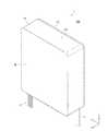
図1は、本発明の一実施形態における接続箱1を示す斜視図である。図1に示すように、接続箱1は、屋外から屋内に導入されたケーブル12(第1のケーブル)と、集合住宅やビルなどの各部屋から延びるケーブル17(第2のケーブル)とを接続させ、ケーブル12から伝送された光情報を各部屋に分配するためのものである。この接続箱1は、集合住宅やビル内の壁面900に固定されている。ここで、本明細書において、Y方向は壁面900の鉛直方向に対応しており、+Y方向側は、壁面900の鉛直方向における上側に、−Y方向側は壁面900の鉛直方向における下側にそれぞれ対応するものである。 FIG. 1 is a perspective view showing a junction box 1 according to an embodiment of the present invention. As shown in FIG. 1, the connection box 1 connects a cable 12 (first cable) introduced indoors from the outside and a cable 17 (second cable) extending from each room such as an apartment house or a building. The optical information transmitted from the
図1に示すように、接続箱1は、X方向及びY方向に延びる基板10と、基板10の+Z方向側を覆うカバー11を有している。基板10は、略正方形の板状部材により形成されている。カバー11は、基板10に垂直なZ方向(奥行方向)に延びており、基板10の縁部から+Z方向(接続箱1に対面する作業者等の側)に延びる枠部11Aと、枠部11Aの+Z方向側を塞ぐ蓋部11Bとが一体的に形成された構造を有している。このような構成により、基板10とカバー11との間に、アダプタや光ファイバなどを収容する収容空間が形成される。図1に示すように、この収容空間には屋外から屋内に導入されたケーブル12が導入されるとともに、屋内の各部屋につながるケーブル17が導出される。 As shown in FIG. 1, the junction box 1 includes a
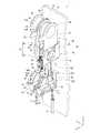
図2は、図1に示す接続箱1のカバー11を取り外した状態における接続箱1を示す平面図である。図2に示すように、接続箱1の基板10には、その四隅にネジ孔15が形成されており、基板10は、これらのネジ孔15と壁面900に形成されたネジ孔(図示せず)とにネジ2を螺合させることによって、壁面900に固定されている。この基板10には、ケーブル12の複数の光ファイバ14の余長が収容されるように光ファイバ14が巻回される余長収容部20と、余長収容部20から導出された光ファイバ14を保持してアダプタ部40にガイドする光ファイバガイド部30と、ケーブル17の複数の光ファイバ13を巻回させつつ、これらの光ファイバ13をアダプタ部40に案内する複数の光ファイバ案内部60と、複数の光ファイバ13のうちアダプタ部40に接続されていない未接続光ファイバ13Aを保留する複数の光ファイバ保留構造50とが設けられている。すなわち、接続箱1は、余長収容部20と、光ファイバガイド部30と、アダプタ部40と、複数の光ファイバ案内部60と、複数の光ファイバ保留構造50とをさらに有している。 FIG. 2 is a plan view showing the connection box 1 with the cover 11 of the connection box 1 shown in FIG. 1 removed. As shown in FIG. 2, screw holes 15 are formed in the four corners of the
図2に示すように、余長収容部20は、基板10の−X方向側(図2の右側)に設けられており、余長収容部20における+X方向側に立設された第1の壁部21Aと、−X方向側に立設された第2の壁部21Bとを含んでいる。第1の壁部21Aは、Y方向に延びる略長楕円形の外形を有しているが、その−X方向側にはY方向の略全長にわたって壁が設けられていない。第2の壁部21Bは、第1の壁部21Aの−X方向側で第1の壁部21Aから離間した位置に立設されており、Y方向に延びる直線状の外形を有している。この第2の壁部21Bは、Y方向における全長が第1の壁部21AのY方向における全長よりもやや短くなるように形成されている。このような構成により、余長収容部20の図2における右下側にケーブルや光ファイバなどを余長収容部20に導入する導入部23が形成され、右上側にケーブルや光ファイバなどを余長収容部20から導出する導出部24が形成される。 As shown in FIG. 2, the surplus
図2に示すように、ケーブル12は、余長収容部20の導入部23から余長収容部20内に導入されている。ケーブル12の複数の光ファイバ14は、この導入部23においてケーブル12から露出されている。露出されたこれらの光ファイバ14は、余長収容部20の第1の壁部21A及び第2の壁部21Bに沿って巻回された後、導出部24から余長収容部20の外部に導出される。このように、余長収容部20で光ファイバ14を必要な巻き数だけ巻回することにより、光ファイバ14の余長が吸収され、光ファイバ14が適切な長さに調整される。 As shown in FIG. 2, the
なお、第1の壁部21A及び第2の壁部21Bの頂部(+Z方向側の部分)には、余長収容部20の内側に向かって突出する複数の突起22が形成されており、このような突起22によって光ファイバ14が余長収容部20から脱落しないようになっている。 A plurality of
図2に示すように、余長収容部20の導出部24から導出された複数の光ファイバ14は、導出部24においてシリコンチューブ16によって束ねられる。そしてこのシリコンチューブ16は、光ファイバガイド部30によって基板10の+Y方向側の部分に保持されるとともに、基板10のX方向における中央部まで案内される。 As shown in FIG. 2, the plurality of
図2に示すように、光ファイバガイド部30は、基板10に固定された第1の部分31と、基板10に可動的に固定された第2の部分32とを含んでいる。第1の部分31は、第1の部分31の−X方向側から+X方向側に向かって次第に下降しながら湾曲する湾曲形状を有している。第2の部分32は、第2の部分32の底部に形成された図示しない凸部が基板10に形成されたスリット33に摺動可能に嵌合することによって基板10に取り付けられている。このスリット33はX方向に延びている。したがって、第2の部分32は、X方向に沿って(第1の部分31に向かって)摺動できるようになっている。この第2の部分32の一部には、第1の部分31の湾曲形状に対応して湾曲する湾曲部32Aが形成されている。このような構成により、第2の部分32を第1の部分31に近づけることにより、第1の部分31と第2の部分32との間に、シリコンチューブ16を基板10の+Y方向側から基板10の中央に向かって案内する案内路34が形成される。シリコンチューブ16は、この案内路34を通って、基板10の中央部に向かって案内される。 As shown in FIG. 2, the optical
なお、第1の部分31及び第2の部分32の頂部には、光ファイバガイド部30の内側に向かって突出する複数の突起35が形成されており、このような突起35によって、シリコンチューブ16が光ファイバガイド部30から脱落しないようになっている。 A plurality of
図2に示すように、複数の光ファイバ14は、光ファイバガイド部30の案内路34から出た(すなわち、基板10の中央部に向かって案内された)シリコンチューブ16から露出されている。これら光ファイバ14の先端のそれぞれには、コネクタ18が接続されている。一方、基板10の中央部には、アダプタ部40が設けられている。このアダプタ部40の上半分には、基板10の中央部に向かって案内された複数の光ファイバ14の数に対応した入力ポート41が設けられている。このような構成により、光ファイバ14の先端に接続されたコネクタ18が、対応するアダプタ部40の入力ポート41に嵌入され、光ファイバ14がアダプタ部40に接続される。 As shown in FIG. 2, the plurality of
図2に示すように、集合住宅やビルの屋内を延びるケーブル17は、屋内の各部屋から延びる複数の光ファイバ13を含んでおり、基板10の左下側から接続箱1内に導入されている。ケーブル17に含まれる複数の光ファイバ13は、ケーブル17の先端側において露出されており、これらの光ファイバ13のそれぞれの先端には、コネクタ19が接続されている。図2に示すように、基板10の左下側には、複数の(本実施形態では2つの)光ファイバ案内部60が設けられている。露出されたこれらの光ファイバ13は、この光ファイバ案内部60によって基板10に対して相対的に近い側(−Z方向側)から相対的に遠い側(+Z方向側)に案内される。また、上述したアダプタ部40の下半分には、光ファイバ13の数に対応した数の出力ポート42が設けられている。 As shown in FIG. 2, the
このような構成により、複数の光ファイバ13は基板10の−Y方向側の部分において基板10に近い側から遠い側に案内され、これらの光ファイバ13の先端に設けられたコネクタ19が対応するアダプタ部40の出力ポート42に嵌入されることにより、光ファイバ13がアダプタ部40に接続される。すなわち、ある部屋から延びる光ファイバ13が、光ファイバ14が接続されているアダプタ部40に接続されることにより、その光ファイバ13と光ファイバ14とが接続され、ケーブル12から伝送された光情報が所定の部屋まで伝送される。 With such a configuration, the plurality of
ところで、基板10の図2における左上側には、複数の(本実施形態では2つの)光ファイバ保留構造50が設けられている。さらに言えば、ケーブル12からの光情報を所望しない部屋や空き部屋が屋内にある場合等、アダプタ部40に接続する必要がない光ファイバ13(以下、このような光ファイバ13を「未接続光ファイバ13A」という。)が存在する場合には、これらの未接続光ファイバ13Aを光ファイバ保留構造50に吊り下げて保留することができるようになっている。 Incidentally, a plurality (two in this embodiment) of optical
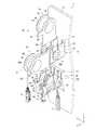
以下、このような光ファイバ保留構造50について詳細に説明する。ここで、図3及び図4は光ファイバ保留構造50と光ファイバ保留構造50の近傍を拡大して示す斜視図であり、図5は光ファイバ保留構造50の保留部80を固定部70から上方(+Y方向)に取り外した際の分解斜視図である。 Hereinafter, such an optical
図3及び図4に示すように、本実施形態における接続箱1は、X方向に近接して配置された2つの光ファイバ保留構造50,50を有している。図5に示すように、光ファイバ保留構造50,50のそれぞれは、基板10に固定されている固定部70と、固定部70に回動可能に固定されている保留部80とを有している。 As shown in FIGS. 3 and 4, the junction box 1 in the present embodiment has two optical
図5に示すように、固定部70は、そのYZ平面が略長方形の板状部材として形成されているが、+Z方向側における上方(+Y方向側)の端部には、固定部70の外側に向かって凸となる湾曲面73が形成されている。さらに言えば、固定部70の縁部は、この湾曲面73と、XZ平面として形成されている第1の平面77と、湾曲面73に接続され、XY平面として形成されている第2の平面78とを含んでいる。第1の平面77のうち−Z方向側の端部近傍には、嵌合凹部76が形成されている。また、固定部70のZ方向における中央部には、固定部70の縁部のうち上方に位置する部分から下方に向かって切り欠かれた切欠き部74が形成されている。 As shown in FIG. 5, the fixed
一方、図5に示すように、光ファイバ保留構造50の保留部80は、保留部80の下半分を構成する回動部81と、保留部80の上半分を構成する保留部本体82と、回動部81と保留部本体82とを段違いに接続する接続部89とを含んでいる。回動部81には軸部83が設けられている。図5の状態において、回動部81は半円形状の外形に形成されており、保留部本体82の先端は半円形状の外形に形成されている。保留部本体82には、保留部本体82から+Z方向側に突出する把手88が形成されている。また、接続部89には、図5に示す状態において接続部89の−Z方向側の端部から−Y方向側に突出する嵌合凸部89Aが形成されている。この嵌合凸部89Aは、後述する回動前状態において、上述の嵌合凹部76に受け入れられて嵌合するように形成されている。 On the other hand, as shown in FIG. 5, the holding
回動部81に設けられた軸部83は、固定部70に形成された切欠き部74に挿入可能に形成されており、軸部83が切欠き部74に挿入されることにより、保留部80が固定部70に対して所定の角度範囲だけ回動できるようになっている。より具体的には、保留部80は、保留部80が基板10に平行に延びている回動前状態(図3参照)から保留部80がZ方向(奥行方向)に延びている回動後状態(図4参照)まで、基板10に対して90°回動できるようになっている。なお、この回動機構については、後に改めて説明する。 The
図5に示すように、保留部80の保留部本体82のうち+Y方向側の部分は、リール状の外形に形成されている。より具体的には、保留部本体82の上縁部86は半円状に形成されており、その上縁部86よりも内側の部分には、保留部本体82から+X方向に延びる円筒状の筒部84が設けられている。そして、この筒部84の+X方向側の端部には、筒部84よりも拡径したフランジ部85が設けられている。 As shown in FIG. 5, a portion on the + Y direction side of the reservation portion
本実施形態によれば、アダプタ部40(図2参照)に接続する必要のない未接続光ファイバ13Aがある場合には、図2及び図3に示すように、未接続光ファイバ13Aを筒部84の円筒面84A(ガイド面)の上半分に巻きつけることにより、基板10に近い側(−Z方向側)から作業者に近い側(+Z方向側)に向かってガイドすることができるため、未接続光ファイバ13Aを作業者に近い側で吊り下げて保留することができる。 According to the present embodiment, when there is an unconnected
また、この未接続光ファイバ13Aをアダプタ部40に接続する必要がある場合には、図4に示すように、接続箱1のカバー11(図1参照)を取り外し、保留部80を基板10に対して90°倒して回動後状態にすることで、未接続光ファイバ13Aを作業者にさらに近い場所まで引き寄せることができる。さらに、上述のように筒部84のX方向における両側には筒部84に対して拡径するフランジ部85と上縁部86とが設けられているため、筒部84の円筒面84Aに巻きつけられて保留された未接続光ファイバ13AがX方向に脱落してしまうことが防止される。 Further, when it is necessary to connect the unconnected
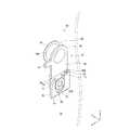
次に、上述した光ファイバ保留構造50の回動機構について詳細に説明する。ここで、図6は、保留部80が固定部70に対して回動する直前の状態を示す斜視図であり、図7は、光ファイバ保留構造50の回動後状態を示す斜視図である。 Next, the rotation mechanism of the optical
図5に示すように、光ファイバ保留構造50の保留部80の回動部81には、軸部83が形成されている。この軸部83は、軸本体83Aと、軸本体83Aの先端において拡径する軸拡径部83Bとを含んでいる。一方、上述したように、固定部70には切欠き部74が形成されているが、図5に示すように、この切欠き部74は、Z方向及びY方向の全長が短い略U字状の第1の切欠き74Aと、Z方向及びY方向の全長が第1の切欠き74Aに比べて長い略U字状の第2の切欠き74Bとを含んでいる。第1の切欠き74AのZ方向における全長及び湾曲部分の直径は、軸本体83Aの直径よりも少し大きくなるように形成されており、第2の切欠き74BのZ方向における全長及び湾曲部分の直径は、軸拡径部83Bの直径よりも少し大きくなるように形成されている。 As shown in FIG. 5, a
図5に示すように、第2の切欠き74Bは第1の切欠き規定面79の内側に形成されている。この第1の切欠き規定面79からは、切欠き部74の内側に向かって延出壁75が延出している。第1の切欠き74Aは、この延出壁75の先端に位置する第2の切欠き規定面75Aの内側に形成されている。 As shown in FIG. 5, the
このような構成により、図6に示すように、固定部70の切欠き部74の+Y方向側の部分から軸部83を切欠き部74に挿入すると、切欠き部74の延出壁75が軸部83の軸拡径部83Bと回動部81との間に挟み込まれ、保留部80が固定部70から脱落してしまうことが防止されるとともに、保留部80が軸部83の軸本体83Aを介して固定部70に対して回動可能に軸支された状態となる。 With such a configuration, as shown in FIG. 6, when the
また、図6に示すように、保留部80の接続部89の−Z方向側における端部には嵌合凸部89Aが形成されており、この嵌合凸部89Aに対応して、固定部70の第1の平面77の−Z方向側における端部には嵌合凹部76が形成されている。このような構成により、軸部83を切欠き部74に挿入させた状態(すなわち、図3に示す回動前状態)では、保留部80の接続部89の一部が固定部70の第1の平面77に載置され、嵌合凸部89Aが嵌合凹部76に嵌合した状態となる。これにより、回動前状態において、保留部80が基板10に平行に延びている状態(すなわち、保留部80と基板10とのなす角が0°の状態)が維持される。 Further, as shown in FIG. 6, a fitting
ここで、上述したように、保留部本体82には把手88が形成されている。したがって、この把手88を指でつまんで保留部80を+Y方向に引き上げることで、図6に示すように、嵌合凸部89Aと嵌合凹部76との嵌合が解除され、保留部80を固定部70に対して回動させることが可能となる。 Here, as described above, the holding portion
保留部80を回動させる際には、把手88をつまんで回動前状態の嵌合凸部89Aと嵌合凹部76との嵌合を解除した後(図6参照)、把手88を手前側(作業者側)に引きつつ、保留部80の接続部89を固定部70の湾曲面73に当接させる。これにより、保留部80は湾曲面73にガイドされつつ、軸部83の軸本体83Aを軸として固定部70に対して回動する。上述したように、この湾曲面73の終端部からは、第2の平面78が基板10と平行に(Y方向に)延びている。 When the holding
図7に示すように、保留部80を回動させていくと、保留部80の接続部89が基板10に対して平行に延びている状態(Y方向に延びている状態)になるが、この際に、作業者が把手88から手を放すと、保留部80は、保留部本体82や未接続光ファイバ13Aに接続されているコネクタ19などから荷重を受け、さらに下方に(すなわち、基板10に対してより大きな角度をなす位置まで)回動しようとする。しかしながら、この状態では、図7に示すように、接続部89の一部が第2の平面78に接触しているため、保留部80のそれ以上の回動が規制される。すなわち、保留部80が基板10に対して90°回動した後、保留部80の回動が規制されることにより、図4に示す回動後状態が維持される。このように、固定部70の第2の平面78は、保留部80の回動を規制する回動規制面として作用する。 As shown in FIG. 7, when the retaining
そして、図4に示すように、光ファイバ保留構造50を上述の回動前状態から回動後状態に移行させることより(すなわち、保留部80を基板10に対して90°回動させることにより)、未接続光ファイバ13Aを作業者のより近くまで引き寄せることができる。 Then, as shown in FIG. 4, the optical
ここで、再び図2及び図4を参照すると、上述の光ファイバ保留構造50,50のそれぞれの下方には、光ファイバ案内部60が設けられている。これらの光ファイバ案内部60,60は、基板10に固定された案内部固定板90を介して基板10に固定されている。 Here, referring to FIGS. 2 and 4 again, an
図8は、接続箱1の基板10の裏面10Aのうち光ファイバ案内部60が設けられている部分を示す図である。図8に示すように、光ファイバ案内部60は、案内部固定板90を貫通して−Z方向側(すなわち、基板10の裏面10A側)に突出する固定突起68を含んでいる。この固定突起68は、図示しない軸部と、この軸部の先端で拡径する拡径部68Aとを含んでいる。 FIG. 8 is a diagram illustrating a portion of the
図8に示すように、案内部固定板90の裏面111には、複数の(本実施形態では3つの)挿入孔112が形成されている。これらの挿入孔112は、瓢箪型に形成されており、+Y方向側に位置する大径部112Aと、−Y方向側に位置する小径部112Bとを含んでいる。大径部112Aの内径は、固定突起68の拡径部68Aの外径よりも大きくなっている。一方、小径部112Bの内径は、拡径部68Aの外径よりも小さく、かつ、固定突起68の軸部の外径よりも大きくなっている。このような構成により、拡径部68Aを大径部112Aに挿通させた上で、固定突起68の軸を−Y方向にずらして拡径部68Aを小径部112B側に移動させることにより、小径部112Bよりも大きな径を有する拡径部68Aが小径部112Bを介して案内部固定板90の裏面111に位置することとなるため、光ファイバ案内部60が小径部112Bから抜け出てしまうことが防止される。このように、光ファイバ案内部60の固定突起68が基板10に形成された挿入孔112に係合することで光ファイバ案内部60が基板10に固定される。 As shown in FIG. 8, a plurality (three in this embodiment) of
図3及び図8に示すように、本実施形態では、それぞれの光ファイバ案内部60に対してY方向に沿って3つの挿入孔112が形成されているため、使用する挿入孔112を変更することにより、光ファイバ案内部60のY方向の固定位置(高さ)を調整することができる。 As shown in FIGS. 3 and 8, in the present embodiment, since the three
図2から図4に示すように、光ファイバ案内部60は、X方向に延びる半円筒状のガイド部62と、ガイド部62の+X方向側の端部でガイド部62から拡径する第1の側部64と、−X方向側の端部でガイド部62から拡径する第2の側部65とを含んでいる。 As shown in FIGS. 2 to 4, the optical
図2から図4に示すように、第1の側部64の+Z方向側の部分には、+Z方向に延出してその先端が−X方向に屈曲している第1の延出部67が設けられている。また、第1の側部64の+Y方向側の部分には、切欠き64Aが形成されている。一方、第2の側部65の+Y方向側の部分には、第1の側部64の切欠き64Aに向かって+X方向に延出する第2の延出部63が設けられている。また、第2の側部65の+Z方向側の部分には、+Z方向に延出してその先端が第1の延出部67の先端部に向かって突出している第3の延出部66が設けられている。第1の延出部67の先端部と第3の延出部66の先端部とは、わずかな隙間がある程度の距離まで近接している。 As shown in FIG. 2 to FIG. 4, a first extending
このような光ファイバ案内部60が設けられていることにより、光ファイバ保留構造50から未接続光ファイバ13Aを取り外した作業者は、例えば、この未接続光ファイバ13Aを第1の延出部67に形成された切欠き64Aから光ファイバ案内部60の内側に引き込み(図4参照)、ガイド部62の円筒面(案内面)62A(図2参照)に沿って巻きつけることで、未接続光ファイバ13Aを基板10に近い側(−Z方向側)から作業者に近い側(+Z方向側)に引き寄せることができる。 By providing such an optical
この際、光ファイバ案内部60の+Y方向側には、第2の側部65から第1の側部64に向かって延出する第2の延出部63が設けられており、光ファイバ案内部60の+Z方向側には、+Z方向に延出して先端部同士が互いに近接する第1の延出部67及び第3の延出部66が設けられており、さらに、ガイド部62のX方向の両側には、ガイド部62から拡径する第1の側部64及び第2の側部65が設けられているため、ガイド部62に巻きつけられた未接続光ファイバ13Aは、光ファイバ案内部60から脱落することなく光ファイバ案内部60に保持される。 At this time, a second extending
以上のように、本実施形態おける接続箱1によれば、アダプタ部40に接続されない未接続光ファイバ13Aを、光ファイバ保留構造50の保留部80によって基板10に近い側から作業者に近い側に引き寄せた上、保留部80から吊り下げて保留することができる。したがって、作業者は、保留されている未接続光ファイバ13Aのそれぞれが、アダプタ部40の出力ポート42のうちどの出力ポートに対応するものであるかを容易に識別することができる。 As described above, according to the connection box 1 in the present embodiment, the unconnected
また、本実施形態における光ファイバ保留構造50は、固定部70に対して回動可能な保留部80を備えているため、保留部80を作業者側に引き寄せた上で所望の未接続光ファイバ13Aを保留部80から取り外すことができるため、所望の未接続光ファイバ13Aを保留部80から取り外すことが容易となる。 Moreover, since the optical
また、ケーブル17に含まれる光ファイバ13の数が多い場合には、図2に示すように、複数の光ファイバ保留構造50を設け、多数の未接続光ファイバ13Aを複数の光ファイバ保留構造50に分散して保留することによって、未接続光ファイバを識別しにくくなることが抑制される。また、このような複数の光ファイバ保留構造を、図2に示すように近接して設けることで、接続箱1の寸法が拡大してしまうことが抑制される。 When the number of
また、複数の光ファイバ保留構造50を近接して設けた場合でも、上述のように保留部80を回動させることができるため、所望の未接続光ファイバが保留されている保留部のみを回動させることによって、所望の光ファイバを保留部から容易に取り外すことができる。 Even when a plurality of optical
このように、本実施形態における光ファイバ保留構造50によれば、所望の未接続光ファイバ13Aを容易に識別することができるとともに、所望の光ファイバを保留部から容易に取り外すことができるため、接続作業の作業効率が向上する。 Thus, according to the optical
さらに、本実施形態における光ファイバ保留構造50によれば、保留部80を基板10に対して平行な状態(すなわち、基板10に対して0°の角度)に維持することができるため、基板10に被せるカバー11の全高を低くすることができる。したがって、接続箱1のスリム化・小型化を実現することができる。 Furthermore, according to the optical
また、本実施形態おける接続箱1は、光ファイバ保留構造50に加えて光ファイバ案内部60を備えているため、所望の未接続光ファイバ13Aを保留部80から取り外した際には、この未接続光ファイバ13Aを光ファイバ案内部60に巻きつけることで、容易に未接続光ファイバ13Aを作業者に近い側に保持することができるため、接続作業の作業効率がさらに向上する。また、図2に示すように、この光ファイバ案内部60に未接続光ファイバ13Aを巻きつけることで、未接続光ファイバ13Aの余長を吸収して適切な長さに調整することで、接続作業の作業効率をより向上させることができる。 In addition, since the junction box 1 in the present embodiment includes the optical
なお、上述の実施形態では、保留部80が基板10と平行になっている状態、すなわち、保留部80が基板10に対して0°(第1の角度)をなしている状態を回動前状態としたが、この第1の角度を任意に変更してもよいことは言うまでもない。ただし、上述のように、第1の角度を0°とすることで、接続箱1の厚みを薄くして接続箱1をスリム化・小型化できるというメリットがある。 In the above-described embodiment, the state in which the
また、上述の実施形態では、回動規制面78を基板10と平行に形成することによって、保留部80を固定部70に対して90°回動させることとしたが、すなわち、第1の角度(0°)から90°(第2の角度)だけ回動させることとしたが、上述の第1の角度は、Z方向(奥行方向)において円筒面84A(ガイド面)が基板10に対して相対的に近くなる角度であり、上述の第2の角度は、Z方向において円筒面84Aが基板10に対して相対的に遠くなる角度であればよい。このような構成でも、未接続光ファイバ13Aを取り外す際に作業者に近い側に引き寄せて作業することが可能である。この場合において、例えば、回動規制面78と基板10とのなす角を調整することによって、基板10に対して平行な状態(第1の角度が0°の状態)から、保留部80を基板に対して60°(第2の角度)だけ回動させることも可能である。 Further, in the above-described embodiment, the
ただし、上述のように、基板10に平行な状態から保留部80を90°回動させることにより、すなわち、第1の角度を0°とし、第2の角度を90°とすることにより、未接続光ファイバ13Aを作業者にもっとも近い側に引き寄せることができるというメリットがある。 However, as described above, by rotating the holding
また、上述の実施形態では、保留部80(接続部89)に嵌合凸部89A(嵌合部)を設け、固定部70(第1の平面77)に嵌合凹部76(被嵌合部)を形成することとしたが、保留部80に嵌合凹部を設け、固定部70に嵌合凸部を設けてもよいことは言うまでもない。また、その他の任意の構成により上述の回動前状態を維持してもよいことは言うまでもない。 Further, in the above-described embodiment, the retaining portion 80 (connecting portion 89) is provided with a fitting
また、上述の実施形態では、固定部70に湾曲面73を形成し、この湾曲面73に保留部80(接続部89)がガイドされることによって保留部80が回動するように構成されているが、必ずしもこのような湾曲面73を固定部70に形成する必要はない。ただし、湾曲面73を形成することによって、湾曲面73の湾曲面に沿って保留部80を回動させることができるため、円滑な回動を実現することができる。 In the above-described embodiment, the
また、上述の実施形態では、保留部本体82に、+Z方向に突出する把手88を形成しているが、必ずしもこのような把手を形成する必要はない。ただし、把手を形成することで、把手を指で摘んで保留部を回動させることができるため、作業が容易になる。 Further, in the above-described embodiment, the
また、上述の実施形態では、光ファイバ保留構造50の保留部80の筒部84を円筒状に形成したが、これに限られるものではない。ただし、円筒状に形成することによって、未接続光ファイバ13Aを円筒面に沿って滑らかに巻きつけることができるため、未接続光ファイバ13Aを巻きつける際に未接続光ファイバ13Aが筒部の角に当たって破損してしまうようなことが防止される。 Moreover, in the above-mentioned embodiment, although the
さらに言えば、保留部80を基板10に対して第1の角度をなす回動前状態から基板に対して第2の角度をなす回動後状態に回動させることができるのであれば、光ファイバ保留構造50の回動機構は上述のものに限られないことは言うまでもない。 Furthermore, if the holding
また、上述の実施形態では、接続箱1の光ファイバ案内部60のガイド部62を半円筒形に形成したが、これに限られるものではない。ただし、半円筒状に形成することによって、未接続光ファイバ13Aを円筒面に沿って滑らかに巻きつけることができるため、未接続光ファイバ13Aを巻きつける際に未接続光ファイバ13Aがガイド部の角に当たって破損してしまうようなことが防止される。 Moreover, in the above-mentioned embodiment, although the
これまで本発明の好ましい実施形態について説明したが、本発明は上述の実施形態に限定されず、その技術的思想の範囲内において種々異なる形態にて実施されてよいことは言うまでもない。 The preferred embodiments of the present invention have been described above, but the present invention is not limited to the above-described embodiments, and it goes without saying that the present invention may be implemented in various forms within the scope of the technical idea.
なお、本明細書において使用した用語「下」、「上」、「底」、「上方」、「下方」、「上側」、「下側」、その他の位置関係を示す用語は、図示した実施形態との関連において使用されているのであり、装置の相対的な位置関係によって変化するものである。 In addition, the terms “lower”, “upper”, “bottom”, “upper”, “lower”, “upper”, “lower”, and other terms indicating the positional relationship used in this specification are the illustrated implementation. It is used in relation to the form, and changes depending on the relative positional relationship of the device.
1 接続箱
10 基板
10A 裏面
11 カバー
11A 枠部
11B 蓋部
12 ケーブル(第1のケーブル)
13 光ファイバ
13A 未接続光ファイバ
14 光ファイバ
15 ネジ孔
16 シリコンチューブ
17 ケーブル(第2のケーブル)
18 コネクタ
19 コネクタ
20 余長収容部
21A 第1の壁部
21B 第2の壁部
22 突起
23 導入部
24 導出部
30 光ファイバガイド部
31 第1の部分
32 第2の部分
32A 湾曲部
33 スリット
34 案内路
35 突起
40 アダプタ部
41 入力ポート
42 出力ポート
50 光ファイバ保留構造
60 光ファイバ案内部
62 ガイド部
62A 円筒面
63 第2の延出部
64 第1の側部
64A 切欠き
65 第2の側部
66 第3の延出部
67 第1の延出部
68 固定突起
68A 拡径部
70 固定部
73 湾曲面
74 切欠き部
74A 第1の切欠き
74B 第2の切欠き
75 延出壁
75A 第2の切欠き規定面
76 嵌合凹部(被嵌合部)
77 第1の平面
78 第2の平面(回動規制面)
79 第1の切欠き規定面
80 保留部
81 回動部
82 保留部本体
83 軸部
83A 軸本体
83B 軸拡径部
84 筒部
84A 円筒面(ガイド面)
85 フランジ部
86 上縁部
88 把手
89 接続部
89A 嵌合凸部(嵌合部)
90 案内部固定板
111 裏面
112 挿入孔
112A 大径部
112B 小径部
900 壁面
DESCRIPTION OF SYMBOLS 1
13
18
77
79 First Notch Specified
85
90 Guide
Claims (9)
Translated fromJapanese前記接続箱の基板に固定された固定部と、
前記基板に対して第1の角度をなす回動前状態から前記基板に対して第2の角度をなす回動後状態まで回動するように前記固定部に軸支された保留部と
を備え、
前記保留部には、前記基板に垂直な奥行方向において前記基板に対して相対的に近い側で延びる前記未接続光ファイバを、前記奥行方向において前記基板に対して相対的に遠い側に案内することにより、前記未接続光ファイバの先端に設けられたコネクタが前記相対的に遠い側で吊り下がっている状態に保留するガイド面が形成されており、
前記第1の角度は、前記奥行方向において前記ガイド面が前記基板に対して相対的に近くなる角度であり、
前記第2の角度は、前記奥行方向において前記ガイド面が前記基板に対して相対的に遠くなる角度である、
光ファイバ保留構造。In a connection box that accommodates an adapter that connects a plurality of optical fibers of a first cable and a plurality of optical fibers of a second cable, to hold unconnected optical fibers that are not connected to the adapter in the connection box The optical fiber holding structure of
A fixing part fixed to the substrate of the connection box;
A holding portion pivotally supported by the fixed portion so as to rotate from a pre-rotation state that forms a first angle with respect to the substrate to a post-rotation state that forms a second angle with respect to the substrate. ,
The holding unit guides the unconnected optical fiber extending on a side relatively close to the substrate in a depth direction perpendicular to the substrate to a side relatively far from the substrate in the depth direction. By this, a guide surface is formed to holdthe connector provided at the tip of the unconnected optical fiber suspended in the relatively far side,
The first angle is an angle at which the guide surface is relatively close to the substrate in the depth direction,
The second angle is an angle at which the guide surface is relatively distant from the substrate in the depth direction.
Optical fiber retention structure.
前記被嵌合部は、前記回動前状態において前記凸部を受け入れるように前記固定部に形成された凹部である、
請求項3に記載の光ファイバ保留構造。The fitting portion is a convex portion that extends from the holding portion toward the fixed portion in the state before the rotation,
The fitted portion is a concave portion formed in the fixed portion so as to receive the convex portion in the state before the rotation.
The optical fiber holding structure according to claim 3.
前記基板と、
前記基板に固定された前記アダプタと、
前記複数の光ファイバを巻回させつつ前記アダプタに案内する光ファイバ案内部と
を備える、接続箱。The optical fiber holding structure according to any one of claims 1 to 7,
The substrate;
The adapter fixed to the substrate;
A connection box comprising: an optical fiber guide portion that guides the adapter while winding the plurality of optical fibers.
前記基板には、前記光ファイバ案内部の前記固定突起に係合可能な複数の挿入孔が形成される
請求項8に記載の接続箱。The optical fiber guide has a fixed protrusion protruding through the substrate;
The junction box according to claim 8, wherein a plurality of insertion holes that can be engaged with the fixing protrusions of the optical fiber guide portion are formed in the substrate.
Priority Applications (2)
| Application Number | Priority Date | Filing Date | Title |
|---|---|---|---|
| JP2017054711AJP6435360B2 (en) | 2017-03-21 | 2017-03-21 | Optical fiber retention structure and junction box |
| PCT/JP2018/006665WO2018173626A1 (en) | 2017-03-21 | 2018-02-23 | Optical fiber holding structure and junction box |
Applications Claiming Priority (1)
| Application Number | Priority Date | Filing Date | Title |
|---|---|---|---|
| JP2017054711AJP6435360B2 (en) | 2017-03-21 | 2017-03-21 | Optical fiber retention structure and junction box |
Publications (2)
| Publication Number | Publication Date |
|---|---|
| JP2018156029A JP2018156029A (en) | 2018-10-04 |
| JP6435360B2true JP6435360B2 (en) | 2018-12-05 |
Family
ID=63586326
Family Applications (1)
| Application Number | Title | Priority Date | Filing Date |
|---|---|---|---|
| JP2017054711AExpired - Fee RelatedJP6435360B2 (en) | 2017-03-21 | 2017-03-21 | Optical fiber retention structure and junction box |
Country Status (2)
| Country | Link |
|---|---|
| JP (1) | JP6435360B2 (en) |
| WO (1) | WO2018173626A1 (en) |
Families Citing this family (1)
| Publication number | Priority date | Publication date | Assignee | Title |
|---|---|---|---|---|
| JP7107978B2 (en)* | 2020-01-16 | 2022-07-27 | 矢崎総業株式会社 | Wire routing method |
Family Cites Families (10)
| Publication number | Priority date | Publication date | Assignee | Title |
|---|---|---|---|---|
| JPS58166310A (en)* | 1982-03-26 | 1983-10-01 | Fujitsu Ltd | Optical cable surplus length processing method |
| DE4229884C2 (en)* | 1992-09-04 | 1994-06-16 | Krone Ag | Device for storing the single and loose tubes of fiber optic cables in distribution facilities for telecommunications and data technology |
| JPH1090525A (en)* | 1996-09-12 | 1998-04-10 | Fujikura Ltd | Optical fiber branch connection device |
| JP2001272550A (en)* | 2000-03-27 | 2001-10-05 | Nippon Comsys Corp | Halter for treating cable slack |
| JP2003121658A (en)* | 2001-10-15 | 2003-04-23 | Fujitsu Ltd | Electronic equipment |
| EP2573602B1 (en)* | 2007-09-06 | 2014-07-09 | Prysmian S.p.A. | Modular system and methods for connecting an external communication network to a user network of a building |
| JP5264633B2 (en)* | 2009-07-02 | 2013-08-14 | 株式会社フジクラ | Optical termination box |
| JP2013024923A (en)* | 2011-07-15 | 2013-02-04 | Panasonic Corp | Termination box |
| US8913867B2 (en)* | 2011-11-21 | 2014-12-16 | Opterna Technology Limited | Fiber optic collector and terminal assemblies |
| US9042702B2 (en)* | 2012-09-18 | 2015-05-26 | Corning Cable Systems Llc | Platforms and systems for fiber optic cable attachment |
- 2017
- 2017-03-21JPJP2017054711Apatent/JP6435360B2/ennot_activeExpired - Fee Related
- 2018
- 2018-02-23WOPCT/JP2018/006665patent/WO2018173626A1/ennot_activeCeased
Also Published As
| Publication number | Publication date |
|---|---|
| WO2018173626A1 (en) | 2018-09-27 |
| JP2018156029A (en) | 2018-10-04 |
Similar Documents
| Publication | Publication Date | Title |
|---|---|---|
| JP3778021B2 (en) | Optical fiber cord surplus length processing apparatus and optical fiber cable housing apparatus incorporating the same | |
| US7065282B2 (en) | Holder and structure for organizing excess length | |
| US7010210B2 (en) | Entry and internal fiber clips for a fiber management system | |
| JP3841344B2 (en) | Optical connection box | |
| US6275641B1 (en) | Fiber tray insertion apparatus and method | |
| JP2013522661A (en) | Terminal enclosure with removable fiber organizing tray | |
| CN102937735A (en) | Fiber optic enclosure with internal cable spool | |
| KR102296297B1 (en) | Cable tray for info-communication with adjustable height and width | |
| KR102105899B1 (en) | Horizontal wiring structure for information communication network of apartment house | |
| JP6348608B2 (en) | Optical enclosure with pre-connected cable reel | |
| JP6435360B2 (en) | Optical fiber retention structure and junction box | |
| JP2021528675A (en) | Rack mount fiber optic splice enclosure | |
| JP2009115962A (en) | Optical connector splicing kit | |
| JP4046046B2 (en) | Floor wiring device | |
| JP4917505B2 (en) | Light rosette | |
| JP5854922B2 (en) | Wire bundle connection support device | |
| TW201926805A (en) | Optical fiber connection box for multi-dwelling unit | |
| KR102296292B1 (en) | Cable tray for info-communication with adjustable height | |
| JP5341487B2 (en) | Splitter module | |
| JP2008096668A (en) | Optical cabinet | |
| JP6469154B2 (en) | Connection box | |
| JP2003149457A (en) | Extra storage jig for plastic optical fiber cord and information outlet | |
| JP4312644B2 (en) | Signal converter | |
| JP4332097B2 (en) | Light outlet | |
| JP2005140826A (en) | Closure for optical cable |
Legal Events
| Date | Code | Title | Description |
|---|---|---|---|
| TRDD | Decision of grant or rejection written | ||
| A01 | Written decision to grant a patent or to grant a registration (utility model) | Free format text:JAPANESE INTERMEDIATE CODE: A01 Effective date:20181106 | |
| A61 | First payment of annual fees (during grant procedure) | Free format text:JAPANESE INTERMEDIATE CODE: A61 Effective date:20181112 | |
| R150 | Certificate of patent or registration of utility model | Ref document number:6435360 Country of ref document:JP Free format text:JAPANESE INTERMEDIATE CODE: R150 | |
| LAPS | Cancellation because of no payment of annual fees |