Movatterモバイル変換


[0]ホーム

URL:


JP6431580B1 - Power control system, supplier power system, control device, and power control method - Google Patents

Power control system, supplier power system, control device, and power control method
Download PDF

Info

Publication number
JP6431580B1
JP6431580B1JP2017151920AJP2017151920AJP6431580B1JP 6431580 B1JP6431580 B1JP 6431580B1JP 2017151920 AJP2017151920 AJP 2017151920AJP 2017151920 AJP2017151920 AJP 2017151920AJP 6431580 B1JP6431580 B1JP 6431580B1
Authority
JP
Japan
Prior art keywords
power
supply
consumer
control
supply source
Prior art date
Legal status (The legal status is an assumption and is not a legal conclusion. Google has not performed a legal analysis and makes no representation as to the accuracy of the status listed.)
Active
Application number
JP2017151920A
Other languages
Japanese (ja)
Other versions
JP2019033566A (en
Inventor
悠 宮崎
悠 宮崎
憲児 高瀬
憲児 高瀬
尚之 竹廣
尚之 竹廣
徹 田中
徹 田中
慶一 廣江
慶一 廣江
一史 湯淺
一史 湯淺
Current Assignee (The listed assignees may be inaccurate. Google has not performed a legal analysis and makes no representation or warranty as to the accuracy of the list.)
NTT DOCOMO BUSINESS, Inc.
Nippon Telegraph and Telephone Corp
NTT Communications Corp
NTT Facilities Inc
NTT Inc
Original Assignee
NTT DOCOMO BUSINESS, Inc.
Nippon Telegraph and Telephone Corp
NTT Communications Corp
NTT Facilities Inc
NTT Inc
Priority date (The priority date is an assumption and is not a legal conclusion. Google has not performed a legal analysis and makes no representation as to the accuracy of the date listed.)
Filing date
Publication date
Application filed by NTT DOCOMO BUSINESS, Inc., Nippon Telegraph and Telephone Corp, NTT Communications Corp, NTT Facilities Inc, NTT IncfiledCriticalNTT DOCOMO BUSINESS, Inc.
Priority to JP2017151920ApriorityCriticalpatent/JP6431580B1/en
Application grantedgrantedCritical
Publication of JP6431580B1publicationCriticalpatent/JP6431580B1/en
Publication of JP2019033566ApublicationCriticalpatent/JP2019033566A/en
Activelegal-statusCriticalCurrent
Anticipated expirationlegal-statusCritical

Links

Images

Classifications

Landscapes

Abstract

Translated fromJapanese

【課題】商用電源を利用する電力需要家の負担を軽減しながら予備電源の利用を可能とする。
【解決手段】電力供給元の供給元電力システム25は、蓄電及び放電を行う蓄電装置256と、商用電力の受電と、蓄電装置256が放電した電力の需要家電力システム35への供給とを制御する給電制御装置251とを備える。電力供給元の需要家電力システム35は、商用電力と供給元電力システム25が送電した電力を受電し、負荷装置353に供給する。制御装置45の制御部453は、商用電力の停電発生時に、需要家電力システム35における予測の電力需要量に基づく放電量の電力を蓄電装置256から放電して需要家電力システム35に供給するよう給電制御装置251に指示する。
【選択図】図5
An object of the present invention is to make it possible to use a standby power supply while reducing the burden on power consumers who use a commercial power supply.
A power supply system of a power supply source 25 controls a power storage device 256 that stores and discharges electric power, receives commercial power, and supplies electric power discharged from the power storage device 256 to a consumer power system 35. The power supply control device 251 is provided. The consumer power system 35 of the power supply source receives the commercial power and the power transmitted by the supply source power system 25 and supplies it to the load device 353. The control unit 453 of the control device 45 discharges the power of the discharge amount based on the predicted power demand amount in the consumer power system 35 from the power storage device 256 and supplies it to the consumer power system 35 when a commercial power failure occurs. The power supply control device 251 is instructed.
[Selection] Figure 5

Description

Translated fromJapanese

本発明は、電力制御システム、供給元電力システム、制御装置及び電力制御方法に関する。The present invention, power control system, the supply source powersystems, tocontrol apparatus and power control method.

近年、省エネルギー・省コスト、BCP(事業継続計画)強化のため、自前で予備電源を具備し、ピークシフト・小売電気事業者等への売電(ポジワット・ネガワット双方含む)などによる省コスト、および一般送配電事業者の電力網停電時のバックアップ電源供給等の運用を実施する企業やビル等が増加している。しかしながら、電力需要家が自身で予備電源を設置する場合、予備電源設置用スペースの確保、予備電源の運用に関する負担増や信頼性の確保などの問題がある。一方、需要家間をAC(Alternate Current:交流)バス及びDC(Direct Current:直流)バスで接続し、親クラスタの需要家から子クラスタの需要家へ電力を供給する電力融通システムがある(例えば、特許文献1参照)。  In recent years, energy saving and cost saving, BCP (Business Continuity Plan) strengthening, self-equipped spare power supply, peak shift, power saving to retail electricity companies (including both positive wattage and negative wattage), etc., and There are an increasing number of companies, buildings, etc. that perform operations such as backup power supply in case of power grid outages of general power transmission and distribution companies. However, when a power consumer installs a spare power supply by himself / herself, there are problems such as securing a space for installing a spare power supply, increasing the burden on the operation of the spare power supply, and ensuring reliability. On the other hand, there is a power interchange system in which consumers are connected by an AC (Alternate Current) bus and a DC (Direct Current: DC) bus to supply power from a customer in a parent cluster to a customer in a child cluster (for example, , See Patent Document 1).

特開2015−177574号公報Japanese Patent Laying-Open No. 2015-177574

上述した従来の電力融通システムは、親クラスタの需要家が商用電力系統の受電点となって子クラスタの需要家へ商用電源を供給する。そのため、各需要家が独立して商用電力を利用しながら、非常時には予備電源からの電力供給を受けるものではない。  In the conventional power interchange system described above, a consumer of a parent cluster serves as a power receiving point for a commercial power system and supplies commercial power to a consumer of a child cluster. Therefore, each customer does not receive power supply from a standby power supply in an emergency while using commercial power independently.

上記事情に鑑み、本発明は、商用電源を利用する電力需要家の省エネルギー・省コスト、BCPに関する負担を軽減しながら予備電源の利用を可能とする電力制御システム、供給元電力システム、制御装置及び電力制御方法を提供することを目的としている。In view of the above circumstances, the present invention is a power control system capable of utilizing the auxiliary power supply while reducing energy and cost saving of the electric power consumers utilizing commercial power, the burden related to BCP, Supplier powersystem, control system It is an object of the present invention to provide a power control method.

本発明の一態様は、電力供給元の供給元電力システムと、電力需要家の需要家電力システムと、制御装置とを有する電力制御システムであって、前記供給元電力システムは、蓄電及び放電を行う蓄電装置と、商用電力の受電と、前記蓄電装置が放電した電力の前記需要家電力システムへの供給とを制御する給電制御部とを備え、前記需要家電力システムは、商用電力と前記供給元電力システムから供給される電力とを受電する受電部と、前記受電部が受電した電力を前記電力需要家の負荷に供給する配電部とを備え、前記制御装置は、商用電力の停電発生時に、前記需要家電力システムにおける予測の電力需要量に基づく電力を前記蓄電装置から放電して前記需要家電力システムに供給するよう前記給電制御部に指示する制御部を備え、前記制御部は、商用電力の停電の発生がない常時に、前記蓄電装置に蓄電された電力量のうち非常時必要分の電力量を確保した上での余剰の電力を、前記需要家電力システムと前記電力供給元の負荷との少なくとも一方に供給する、又は、売電のための電力網に送電するよう前記給電制御部に指示し、前記制御部は、前記予測の電力需要量に基づく電力と、保守者が前記供給元電力システムの場所に移動するためにかかる予測時間とに基づいて、前記非常時必要分の電力量を算出する。One aspect of the present invention is a power control system having a power supply source power system, a power consumer power system, and a control device, wherein the power supply system stores and discharges electricity. A power supply control unit that controls a power storage device to perform, receiving commercial power, and supplying power discharged from the power storage device to the consumer power system, wherein the consumer power system includes commercial power and the supply A power receiving unit that receives the power supplied from the original power system; and a power distribution unit that supplies the power received by the power receiving unit to the load of the power consumer. includes a control unit that instructs the power supply controller to supply basedKu power to the power demand of prediction in the demand consumer electronics power system to the demand consumer electronics power systems discharged from said electrical storagedevice, wherein The control unit, when there is no power outage of commercial power, always keeps the surplus power after securing the amount of power necessary for emergency out of the amount of power stored in the power storage device as the customer power system. Supply to at least one of the power supply source loads, or instruct the power supply control unit to transmit power to the power network for power sale, the control unit, the power based on the predicted power demand, maintenance person on the basis of the expected time to move to the location of the supply source power system, it calculates the amount of power of the emergency needs min.

また、本発明の一態様は、上述の電力制御システムであって、前記給電制御部は、商用電力及び前記蓄電装置が放電した電力の前記電力供給元の負荷への供給をさらに制御し、前記制御部は、商用電力の停電発生時に、前記需要家電力システム及び前記供給元電力システムにおける予測の電力需要量に基づく電力を前記蓄電装置から放電し、前記需要家電力システムと前記電力供給元の負荷とに供給するよう前記給電制御部に指示する。One embodiment of the present invention is the above-described power control system, wherein the power supply control unit further controls supply of commercial power and power discharged from the power storage device to the load of the power supply source, control unit, when a power failure occurs in the commercial power, the basedKu power to the power demand of prediction in the demand consumer electronics power system and the supply source power system discharged from said electrical storage device, wherein said demand consumer electronics power system power The power supply control unit is instructed to supply to the supply source load.

また、本発明の一態様は、上述の電力制御システムであって、前記制御部は、前記蓄電装置から供給可能な電力量が前記予測の電力需要量に満たない場合に、前記電力需要家の負荷あるいは前記電力供給元の負荷の一部への電力供給を制限するよう制御する。Further, one aspect of the present invention is the above-described power control system, in which the control unit includes the power consumer when the amount of power that can be supplied from the power storage device is less than the predictedpower demand. Control is performed so as to limit power supply to theload or a partof the load of thepower supply source .

また、本発明の一態様は、上述の電力制御システムであって、前記電力制御システムは、複数の前記供給元電力システムを有し、前記制御部は、複数の前記供給元電力システムそれぞれの前記蓄電装置から供給可能な電力量と、1以上の前記需要家電力システムそれぞれにおける前記予測の電力需要量とに基づいて、前記需要家電力システムそれぞれに電力を供給する前記供給元電力システムを決定する。  One aspect of the present invention is the above-described power control system, wherein the power control system includes a plurality of the supply source power systems, and the control unit includes the plurality of the supply source power systems. The source power system that supplies power to each of the consumer power systems is determined based on the amount of power that can be supplied from the power storage device and the predicted power demand of each of the one or more consumer power systems. .

また、本発明の一態様は、上述の電力制御システムであって、前記制御部は、前記蓄電装置からの電力の供給先となる前記需要家電力システムが複数あり、かつ、前記蓄電装置から供給可能な電力量が供給先の前記予測の電力需要量の合計に満たない場合に、前記蓄電装置が放電した電力を、前記需要家電力システムの優先度に基づいて選択された前記需要家電力システムへ供給するよう制御する。  One embodiment of the present invention is the above-described power control system, in which the control unit includes a plurality of the consumer power systems to which power is supplied from the power storage device, and is supplied from the power storage device. The customer power system in which the power discharged from the power storage device is selected based on the priority of the customer power system when the possible power amount is less than the total predicted power demand of the supply destination Control to supply to.

また、本発明の一態様は、上述の電力制御システムであって、前記制御部は、前記蓄電装置から供給可能な電力量が供給先の前記予測の電力需要量の合計に満たない場合に、前記需要家電力システムの供給要求電力の優先度及び前記予測の電力需要量に基づいて前記需要家電力システムへの電力供給量を決定し、前記蓄電装置が放電した電力を決定した前記電力供給量に従って前記需要家電力システムへ供給するよう制御する。  One embodiment of the present invention is the above-described power control system, in which the control unit is configured such that the amount of power that can be supplied from the power storage device is less than the total of the predicted power demand of the supply destination. The power supply amount that determines the power supply amount to the consumer power system based on the priority of the required power supply of the consumer power system and the predicted power demand amount, and determines the power discharged by the power storage device To control the supply to the consumer power system.

また、本発明の一態様は、上述の電力制御システムであって、前記受電部は、前記供給元電力システムから供給される電力を交流と直流の何れか又は両方により受電する。  One embodiment of the present invention is the above-described power control system, in which the power reception unit receives power supplied from the supply source power system by either or both of AC and DC.

また、本発明の一態様は、上述の電力制御システムであって、前記制御部は、前記予測の電力需要量を、過去、現在及び予測の前記負荷の電力消費量及び天候の情報と、時間の情報等とのうち少なくとも一部に基づいて算出する。  One aspect of the present invention is the above-described power control system, wherein the control unit is configured to calculate the predicted power demand, past, present, and predicted power consumption and weather information of the load, and time. It is calculated based on at least a part of the information and the like.

本発明の一態様は、電力供給元の供給元電力システムと、電力需要家の需要家電力システムと、制御装置とを有する電力制御システムにおける前記供給元電力システムであって、蓄電及び放電を行う蓄電装置と、商用電力の受電と、前記蓄電装置が放電した電力の前記需要家電力システムへの供給とを制御する給電制御部と、を備え、前記給電制御部は、前記制御装置からの指示に従って、商用電力の停電発生時に、前記需要家電力システムにおける予測の電力需要量に基づく電力を前記蓄電装置から放電して前記需要家電力システムに供給するよう制御し、前記給電制御部は、前記制御装置からの指示に従って、商用電力の停電の発生がない常時に、前記蓄電装置に蓄電された電力量のうち非常時必要分の電力量を確保した上での余剰の電力を、前記需要家電力システムと前記電力供給元の負荷との少なくとも一方に供給する、又は、売電のための電力網に送電するよう制御し、前記非常時必要分の電力量は、前記予測の電力需要量に基づく電力と、保守者が前記供給元電力システムの場所に移動するためにかかる予測時間とに基づいて算出されるOne aspect of the present invention is the above-described power source power system in a power control system having a power source power source power system, a power consumer power system, and a control device, which stores and discharges electricity. A power supply control unit that controls power storage device, receiving of commercial power, and supply of power discharged from the power storage device to the consumer power system, the power supply control unit is an instruction from the control device according, when the power generation of the commercial power,and controls to supply basedKu power to the power demand of prediction in the demand consumer electronics power system to the demand consumer electronics power system by the discharge from the electric storagedevice, the power supply control unit In accordance with an instruction from the control device, the surplus power after securing the necessary amount of emergency power out of the amount of power stored in the power storage device at any time without occurrence of a commercial power outage Is supplied to at least one of the consumer power system and the load of the power supply source, or is transmitted to a power grid for power sale, and the amount of power necessary for emergency is calculated as follows. It is calculated based on the power based on the power demand and the estimated time required for the maintenance person to move to the place of the power supply system .

また、本発明の一態様は、電力供給元の供給元電力システムと、電力需要家の需要家電力システムと、制御装置とを有する電力制御システムにおける前記制御装置であって、商用電力の停電発生時に、前記需要家電力システムにおける予測の電力需要量に基づく電力を、蓄電及び放電を行う蓄電装置から放電して前記需要家電力システムに供給するよう前記供給元電力システムに指示する制御部、を備え、前記制御部は、商用電力の停電の発生がない常時に、前記蓄電装置に蓄電された電力量のうち非常時必要分の電力量を確保した上での余剰の電力を、前記需要家電力システムと前記電力供給元の負荷との少なくとも一方に供給する、又は、売電のための電力網に送電するよう前記供給元電力システムに指示し、前記制御部は、前記予測の電力需要量に基づく電力と、保守者が前記供給元電力システムの場所に移動するためにかかる予測時間とに基づいて、前記非常時必要分の電力量を算出する。According to another aspect of the present invention, there is provided a control device in a power control system including a power supply source power system, a power consumer power system, and a control device, wherein a commercial power outage occurs. sometimes, the control instructing basedKu power to the power demand of prediction in the demand consumer electronics power system, to the supply source power system to be discharged from the power storage device performing a power storage and discharge supplying to the demand consumer electronics power system Thecontrol unit, at any time without the occurrence of a power outage of commercial power, surplus power after securing the amount of power necessary for emergency out of the amount of power stored in the power storage device, Supplying to at least one of the customer power system and the load of the power supply source, or instructing the supply source power system to transmit power to a power network for power sale, the control unit And electric power based on the power demand, maintenance person on the basis of the expected time to move to the location of the supply source power system, it calculates the amount of power of the emergency needs min.

また、本発明の一態様は、電力供給元の供給元電力システムと、電力需要家の需要家電力システムと、制御装置とを有する電力制御システムにおいて実行される電力制御方法であって、前記供給元電力システムが、商用電力の受電と、蓄電及び放電を行う蓄電装置が放電した電力の前記需要家電力システムへの供給とを制御する給電制御ステップと、前記需要家電力システムが、商用電力と前記供給元電力システムから供給される電力とを受電し、受電した電力を前記電力需要家の負荷に供給する受電ステップと、を有し、前記給電制御ステップにおいては、商用電力の停電発生時に、前記制御装置からの指示に従って、前記需要家電力システムにおける予測の電力需要量に基づく電力を前記蓄電装置から放電して前記需要家電力システムに供給するよう制御し、前記給電制御ステップにおいては、商用電力の停電の発生がない常時に、前記制御装置からの指示に従って、前記蓄電装置に蓄電された電力量のうち非常時必要分の電力量を確保した上での余剰の電力を、前記需要家電力システムと前記電力供給元の負荷との少なくとも一方に供給する、又は、売電のための電力網に送電するよう制御し、前記非常時必要分の電力量は、前記予測の電力需要量に基づく電力と、保守者が前記供給元電力システムの場所に移動するためにかかる予測時間とに基づいて算出されるMoreover, one aspect of the present invention is a power control method executed in a power control system including a power supply source power system, a power consumer power system, and a control device, wherein the supply A power supply control step in which an original power system controls receiving of commercial power and supply of power discharged by a power storage device that stores and discharges to the consumer power system, and the consumer power system includes commercial power and A power receiving step of receiving power supplied from the power supply system and supplying the received power to a load of the power consumer, and in the power supply control step, when a power failure occurs in commercial power, in accordance with an instruction from the control unit, the basedKu power to the power demand of prediction in the demand consumer electronics power system to the demand consumer electronics power systems discharged from said electrical storage deviceControls tosupply, in the power supply control step, always there is no power failure of the commercial power, in accordance with an instruction from the control device, the electric energy of an emergency need fraction of the amount of power stored in the electricity to the electrical storage device To supply at least one of the consumer power system and the load of the power supply source, or to transmit the surplus power to the power grid for power sale, and for the emergency The power amount of the minute is calculated based on the power based on the predicted power demand amount and the predicted time required for the maintenance person to move to the place of the supply source power system .

本発明により、商用電源を利用する電力需要家の省エネルギー・省コスト、BCPに関する負担を軽減しながら予備電源の利用を可能とすることができる。  According to the present invention, it is possible to make it possible to use a standby power supply while reducing the energy and cost savings of a power consumer using a commercial power supply and the burden on the BCP.

本発明の第1の実施形態による電力制御システムの構成を示す機能ブロック図である。It is a functional block diagram which shows the structure of the electric power control system by the 1st Embodiment of this invention.第2の実施形態による電力制御システムの構成を示す機能ブロック図である。It is a functional block diagram which shows the structure of the electric power control system by 2nd Embodiment.第3の実施形態による電力制御システムの構成を示す機能ブロック図である。It is a functional block diagram which shows the structure of the power control system by 3rd Embodiment.第4の実施形態による電力制御システムの動作概要を示す図である。It is a figure which shows the operation | movement outline | summary of the power control system by 4th Embodiment.同実施形態による電力制御システムの構成を示す機能ブロック図である。It is a functional block diagram which shows the structure of the power control system by the embodiment.同実施形態による電力需要家の契約条件を示す図である。It is a figure which shows the contract conditions of the electric power consumer by the embodiment.同実施形態による電力制御システムの電力需要ピーク時期における非常時の電力需要家への電力供給例を示す図である。It is a figure which shows the example of the electric power supply to the electric power consumer at the time of an emergency in the electric power demand peak time of the electric power control system by the embodiment.同実施形態による電力制御システムの電力需要オフピーク時期における非常時の電力需要家への電力供給例を示す図である。It is a figure which shows the example of the electric power supply to the electric power consumer in the emergency in the electric power demand off-peak time of the electric power control system by the embodiment.同実施形態による電力制御システムにおける非常時の電源供給処理を示すフロー図である。It is a flowchart which shows the power supply process at the time of emergency in the power control system by the embodiment.第5の実施形態による電力制御システムの動作概要を示す図である。It is a figure which shows the operation | movement outline | summary of the electric power control system by 5th Embodiment.同実施形態による電力制御システムの構成を示す機能ブロック図である。It is a functional block diagram which shows the structure of the power control system by the embodiment.第6の実施形態による電力制御システムの動作概要を示す図である。It is a figure which shows the operation | movement outline | summary of the electric power control system by 6th Embodiment.同実施形態による電力制御システムの構成を示す機能ブロック図である。It is a functional block diagram which shows the structure of the power control system by the embodiment.同実施形態による電力制御システムにおける蓄電池マネジメントの例を説明するための図である。It is a figure for demonstrating the example of the storage battery management in the electric power control system by the embodiment.同実施形態による電力制御システムにおける保守者リアルタイム位置情報と連動した蓄電池マネジメント処理を示すフロー図である。It is a flowchart which shows the storage battery management process linked with the maintenance person real-time position information in the electric power control system by the embodiment.

以下、図面を参照しながら本発明の実施形態を詳細に説明する。  Hereinafter, embodiments of the present invention will be described in detail with reference to the drawings.

[第1の実施形態]
本実施形態では、企業やビル等の電力需要家が、省エネルギー・省コスト、BCP(事業継続計画)強化のために利用する予備電源の運用を、他の企業やビル等の電力供給元にアウトソースする。電力供給元においても、この予備電源を利用可能である。本実施形態では、電力供給元と電力需要家とを1対1で接続する。
[First Embodiment]
In the present embodiment, power consumers such as companies and buildings outsource the operation of standby power used for energy and cost saving and BCP (Business Continuity Plan) enhancement to other companies and buildings and other power supply sources. To source. This spare power source can also be used at the power supply source. In this embodiment, a power supply source and a power consumer are connected on a one-to-one basis.

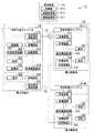
図1は、本発明の第1の実施形態による電力制御システム10の構成を示す機能ブロック図であり、本実施形態と関係する機能ブロックのみを抽出して示してある。電力制御システム10は、電力供給元の供給元電力システム20と、電力需要家の需要家電力システム30と、供給元電力システム20及び需要家電力システム30を制御する制御装置40とを有する。供給元電力システム20は、電力供給拠点となる電力供給元のビル等の施設に備えられ、需要家電力システム30は、電力需要拠点となる電力需要家のビル等の施設に備えられる。  FIG. 1 is a functional block diagram showing a configuration of thepower control system 10 according to the first embodiment of the present invention, and only functional blocks related to the present embodiment are extracted and shown. Thepower control system 10 includes asupply power system 20 that is a power supply source, aconsumer power system 30 that is a power consumer, and acontrol device 40 that controls thesupply power system 20 and theconsumer power system 30. The powersource power system 20 is provided in a facility such as a power supply source building serving as a power supply base, and thecustomer power system 30 is provided in a facility such as a power consumer building serving as a power demand base.

供給元電力システム20と需要家電力システム30とは、交流系統網51及び直流系統網52により接続される。なお、供給元電力システム20と需要家電力システム30とが、交流系統網51のみ又は直流系統網52のみにより接続されてもよい。交流系統網51は、例えば、一般送配電事業者の電力網であり、交流電力が流れる電力網である。交流系統網51が一般送配電事業者以外のものによって独自に敷設された交流電力の電力網である場合、供給元電力システム20及び需要家電力システム30には、交流系統網51とは別の交流系統網により商用電力が供給される。直流系統網52は、直流電力が流れる電力網であり、一般送配電事業者が敷設した送電網、若しくは、電力供給元と電力需要家の間で敷設された自営線網である。制御装置40と、供給元電力システム20及び需要家電力システム30とは、通信網53を介して通信する。通信網53は、有線/無線を問わない。  Thesupplier power system 20 and thecustomer power system 30 are connected by anAC grid network 51 and aDC grid network 52. Thesupplier power system 20 and theconsumer power system 30 may be connected only by theAC grid network 51 or only by the DCgrid network 52. TheAC system network 51 is, for example, a power network of a general power transmission and distribution company, and is a power network through which AC power flows. When theAC system network 51 is an AC power network independently laid by a person other than the general power transmission / distribution company, the supplysource power system 20 and theconsumer power system 30 have an AC power different from theAC system network 51. Commercial power is supplied by the grid. The DCsystem network 52 is a power network through which DC power flows, and is a power transmission network laid by a general power transmission / distribution company or a private line network laid between a power supply source and a power consumer. Thecontrol device 40 communicates with the supplysource power system 20 and thecustomer power system 30 via thecommunication network 53. Thecommunication network 53 may be wired / wireless.

供給元電力システム20は、発電機201、非常用発電機202、蓄電池203、交流潮流制御装置211、受電装置212、配電装置213、直流電源装置214、配電装置215、直流潮流制御装置216、負荷221及び負荷222を備える。  Thepower supply system 20 includes agenerator 201, anemergency generator 202, astorage battery 203, an AC powerflow control device 211, apower receiving device 212, apower distribution device 213, a DCpower supply device 214, apower distribution device 215, a DC powerflow control device 216, a load. 221 and aload 222.

発電機201は、例えば、太陽光発電機や風力発電機などであり、常時・非常時に自家発電を行う発電機である。非常用発電機202は、例えば、燃料電池やエンジン発電装置などであり、非常時に自家発電を行う発電機である。発電機201、非常用発電機202は配電装置213又は受電装置212に接続されるが、以下では配電装置213に接続される場合を例に説明する。蓄電池203は、例えば、リチウムイオン電池などの二次電池であり、商用電力や発電機201による発電電力、非常用発電機202による発電電力を蓄電する。  Thepower generator 201 is, for example, a solar power generator or a wind power generator, and is a power generator that performs self-power generation at all times or in an emergency. Theemergency generator 202 is, for example, a fuel cell or an engine generator, and is a generator that performs private power generation in an emergency. Thegenerator 201 and theemergency generator 202 are connected to thepower distribution device 213 or thepower receiving device 212. Hereinafter, a case where thepower generator 201 and theemergency generator 202 are connected to thepower distribution device 213 will be described as an example. Thestorage battery 203 is, for example, a secondary battery such as a lithium ion battery, and stores commercial power, power generated by thegenerator 201, and power generated by theemergency generator 202.

交流潮流制御装置211は、制御装置40の指示に従い、交流系統網51から商用電力の供給を受けるか、受電装置212から受電した交流電力を交流系統網51へ送電するかの交流電力の潮流の切替を行う。交流系統網51への送電は、非常時や省エネルギーのために需要家電力システム30へ電力を供給するときや、小売電気事業者等へ売電するときに行われる。  The AC powerflow control device 211 receives the supply of commercial power from theAC grid network 51 or transmits AC power received from thepower receiving device 212 to theAC grid network 51 in accordance with an instruction from thecontrol device 40. Switch. The power transmission to theAC network 51 is performed when power is supplied to thecustomer power system 30 in case of emergency or energy saving, or when power is sold to a retail electric company.

受電装置212は、交流潮流制御装置211が商用電力を受電している場合、交流潮流制御装置211から受電した商用電力の電圧を変換して配電装置213へ送電する。受電装置212は、交流潮流制御装置211が交流系統網51へ交流電力を送電する場合、配電装置213から受電した交流電力の電圧を変換して交流潮流制御装置211に送電する。  When the AC powerflow control device 211 is receiving commercial power, thepower receiving device 212 converts the commercial power voltage received from the AC powerflow control device 211 and transmits the converted power to thepower distribution device 213. When the AC powerflow control device 211 transmits AC power to theAC grid network 51, thepower receiving device 212 converts the voltage of the AC power received from thepower distribution device 213 and transmits it to the AC powerflow control device 211.

配電装置213は、電力の分岐を行う。配電装置213は、発電機201及び非常用発電機202が発電した電力を受電する。配電装置213は、交流潮流制御装置211が商用電力を受電している場合、受電装置212からの交流電力の受電と、負荷221及び直流電源装置214への送電をさらに行い、交流潮流制御装置211が交流電力を送電している場合、直流電源装置214からの交流電力の受電と、負荷221及び受電装置212への送電をさらに行う。また、配電装置213は、制御装置40からの指示を受け、一部の負荷221への電力供給を停止または抑制する負荷抑制制御を行う。  Thepower distribution device 213 performs power branching. Thepower distribution device 213 receives power generated by thegenerator 201 and theemergency generator 202. When the AC powerflow control device 211 is receiving commercial power, thepower distribution device 213 further receives AC power from thepower reception device 212 and transmits power to theload 221 and the DCpower supply device 214, and the AC powerflow control device 211. In the case of transmitting AC power, the AC power reception from the DCpower supply device 214 and the power transmission to theload 221 and thepower reception device 212 are further performed. In addition, thepower distribution apparatus 213 receives an instruction from thecontrol apparatus 40 and performs load suppression control that stops or suppresses power supply to some of theloads 221.

直流電源装置214は、配電装置213から受電した電力を交流から直流に変換し、配電装置215へ、又は、配電装置215及び蓄電池203へ送電する。また、直流電源装置214は、蓄電池203から放電された電力を交流に変換して配電装置213に送電し、配電装置215には直流のまま送電する。なお、直流電源装置214は交流から直流に変換する装置に加え、直流から交流に変換する装置を並列接続することで、双方向の電力供給が可能となる構成も含まれる。直流電源装置214から配電装置215へ送電される電力量は、負荷222における消費電力と、直流系統網52を介して需要家電力システム30への供給される直流電力との合計の電力量である。  The DCpower supply device 214 converts the power received from thepower distribution device 213 from alternating current to direct current, and transmits the power to thepower distribution device 215 or to thepower distribution device 215 and thestorage battery 203. Further, the DCpower supply device 214 converts the electric power discharged from thestorage battery 203 into alternating current and transmits it to thepower distribution device 213, and transmits power to thepower distribution device 215 without changing the direct current. Note that the DCpower supply device 214 includes a configuration that enables bidirectional power supply by connecting in parallel a device that converts DC to AC in addition to a device that converts AC to DC. The amount of power transmitted from the DCpower supply device 214 to thepower distribution device 215 is the total amount of power consumed by theload 222 and the DC power supplied to thecustomer power system 30 via theDC network 52. .

配電装置215は、電力の分岐を行う。配電装置215は、直流電源装置214から受電した直流電力を負荷222に供給し、供給元電力システム20が需要家電力システム30へ直流電力を供給している場合は、さらに、直流電源装置214から受電した直流電力を直流潮流制御装置216に送電する。また、配電装置215は、制御装置40からの指示を受け、一部の負荷222への電力供給を停止する負荷抑制制御を行う。  Thepower distribution device 215 performs power branching. Thepower distribution apparatus 215 supplies the DC power received from the DCpower supply apparatus 214 to theload 222. When thesupply power system 20 supplies DC power to theconsumer power system 30, thepower distribution apparatus 215 further The received DC power is transmitted to the DC powerflow control device 216. In addition, thepower distribution apparatus 215 receives an instruction from thecontrol apparatus 40 and performs load suppression control for stopping power supply to some of theloads 222.

直流潮流制御装置216は、制御装置40の指示に従い、配電装置215が出力した直流電力を需要家電力システム30に供給するか否かを切替える。直流潮流制御装置216からの直流電力は、直流系統網52を介して需要家電力システム30へ供給される。  The DC powerflow control device 216 switches whether to supply the DC power output from thepower distribution device 215 to theconsumer power system 30 in accordance with an instruction from thecontrol device 40. DC power from the DC powerflow control device 216 is supplied to thecustomer power system 30 via theDC network 52.

負荷221は、交流電力により動作する機器であり、負荷222は、直流電力により動作する機器である。  Theload 221 is a device that operates with AC power, and theload 222 is a device that operates with DC power.

需要家電力システム30は、受電装置311、配電装置312、直流電源装置313、配電装置314、負荷321及び負荷322を備える。
受電装置311は、交流系統網51からの電力の供給を検出した場合、交流系統網51から供給される交流電力の電圧を変換して配電装置312に出力する。また、受電装置311は、交流系統網51からの電力供給の停止や再開を検出し、制御装置40へ通知する。
Thecustomer power system 30 includes apower receiving device 311, apower distribution device 312, a DCpower supply device 313, apower distribution device 314, aload 321 and aload 322.
When detecting the supply of power from theAC grid network 51, thepower receiving apparatus 311 converts the voltage of the AC power supplied from theAC grid network 51 and outputs the converted voltage to thepower distribution apparatus 312. In addition, thepower receiving device 311 detects the stop or restart of the power supply from theAC grid network 51 and notifies thecontrol device 40 of it.

配電装置312は、電力の分岐を行う。配電装置312は、受電装置311から交流電力を受電し、直流電源装置313及び負荷321に送電する。また、配電装置312は、交流系統網51からの交流電力を受電できないとき、又は、交流系統網51からの受電した交流電力が負荷321による消費電力を下回るときには、直流電源装置313から交流電力を受電し、負荷321に送電する。配電装置312は、制御装置40からの指示を受け、一部の負荷321への電力供給を停止する負荷抑制制御を行う。  Thepower distribution apparatus 312 performs power branching. Thepower distribution device 312 receives AC power from thepower receiving device 311 and transmits the AC power to the DCpower supply device 313 and theload 321. Thepower distribution device 312 receives AC power from the DCpower supply device 313 when AC power from theAC grid network 51 cannot be received, or when AC power received from theAC grid network 51 is lower than power consumption by theload 321. The power is received and transmitted to theload 321. In response to the instruction from thecontrol device 40, thepower distribution device 312 performs load suppression control that stops power supply to some of theloads 321.

直流電源装置313は、配電装置312から受電した電力を交流から直流に変換し、配電装置314へ送電する。また、直流電源装置313は、配電装置314から受電した電力を直流から交流に変換し、配電装置312へ送電する。  The DCpower supply device 313 converts the power received from thepower distribution device 312 from alternating current to direct current, and transmits the power to thepower distribution device 314. In addition, the DCpower supply device 313 converts the power received from thepower distribution device 314 from DC to AC and transmits the power to thepower distribution device 312.

配電装置314は、電力の分岐を行う。また、配電装置314は、制御装置40からの指示を受け、一部の負荷322への電力供給を停止する負荷抑制制御を行う。配電装置314は、切替装置315を備える。切替装置315は、制御装置40からの指示を受け、直流電源装置313から受電した直流電力を負荷322に供給するか、直流系統網52を介して供給元電力システム20から供給された直流電力を直流電源装置313及び負荷322に送電するかを切替える。  Thepower distribution device 314 branches power. In addition, thepower distribution device 314 receives an instruction from thecontrol device 40 and performs load suppression control for stopping power supply to some of theloads 322. Thepower distribution device 314 includes aswitching device 315. Theswitching device 315 receives an instruction from thecontrol device 40 and supplies the DC power received from the DCpower supply device 313 to theload 322 or the DC power supplied from the supplysource power system 20 via theDC network 52. Whether to transmit power to theDC power supply 313 and theload 322 is switched.

なお、需要家電力システム30は、太陽光発電機や風力発電機など、自家発電を行う発電機を備えてもよい。この場合、発電機は、発電した電力を配電装置312又は受電装置311に送電する。  Theconsumer power system 30 may include a generator that performs private power generation, such as a solar power generator or a wind power generator. In this case, the generator transmits the generated power to thepower distribution device 312 or thepower receiving device 311.

制御装置40は、情報収集部401、情報記憶部402及び制御部403を備える。情報収集部401は、供給元電力システム20及び需要家電力システム30から、各監視項目の状態を表す状態情報を収集する。また、情報収集部401は、天候(気温、湿度)の情報や、売電時の取引価格の情報などを図示しない外部の装置から収集する。情報記憶部402は、情報収集部401が収集した状態情報の履歴であるログデータや、外部の装置から収集した情報の履歴を記憶する。ログデータは、状態情報の収集元のシステムを特定するシステム識別情報と、システム識別情報により特定される供給元電力システム20又は需要家電力システム30から収集された状態情報と、状態情報が得られた時刻を示す時刻情報とを対応付けた情報である。  Thecontrol device 40 includes aninformation collection unit 401, aninformation storage unit 402, and acontrol unit 403. Theinformation collection unit 401 collects state information indicating the state of each monitoring item from the supplysource power system 20 and theconsumer power system 30. In addition, theinformation collection unit 401 collects information on weather (temperature, humidity), information on transaction prices at the time of power sale, and the like from an external device (not shown). Theinformation storage unit 402 stores log data that is a history of state information collected by theinformation collection unit 401 and a history of information collected from an external device. The log data includes system identification information for identifying a system from which the state information is collected, state information collected from the supplysource power system 20 or thecustomer power system 30 identified by the system identification information, and state information. It is the information which matched the time information which shows the time.

情報収集部401は、例えば、以下の状態情報の一部又は全てを周期的に取得する。なお、情報収集部401が各状態情報を収集する時刻や収集を行う周期の長さは異なっていてもよい。  For example, theinformation collection unit 401 periodically acquires part or all of the following state information. Note that the time at which theinformation collection unit 401 collects each state information and the length of the collection period may be different.

(1)供給元電力システム20における商用電力の受電量、及び、供給元電力システム20から交流系統網51への送電量。例えば、これらの情報は、供給元電力システム20の交流潮流制御装置211から得られる。
(2)発電機201、非常用発電機202それぞれの発電量。例えば、これらの情報は、発電機201及び非常用発電機202のそれぞれから、又は、配電装置213から得られる。
(3)負荷221及び負荷222の消費電力量。例えば、これらの情報はそれぞれ、配電装置213及び配電装置215から得られる。
(4)蓄電池203における蓄電量及び放電量。例えば、これらの情報は、蓄電池203及び直流電源装置214から得られる。
(5)供給元電力システム20から直流系統網52への送電量。例えば、この情報は、直流潮流制御装置216から得られる。
(6)需要家電力システム30における交流電力の受電量。例えば、この情報は、受電装置311から得られる。
(7)負荷321及び負荷322の消費電力量。例えば、これらの情報はそれぞれ、配電装置312及び配電装置314から得られる。
(8)需要家電力システム30における直流電力の受電量。例えば、この情報は、配電装置314から得られる。
(9)需要家電力システム30が発電機を備える場合、その発電量。例えば、この情報は、発電機又は配電装置312から得られる。
(1) Amount of commercial power received in the supplysource power system 20 and a transmission amount from the supplysource power system 20 to theAC grid network 51. For example, these pieces of information are obtained from the AC powerflow control device 211 of the supplysource power system 20.
(2) Amount of power generated by each of thegenerator 201 and theemergency generator 202. For example, these pieces of information are obtained from each of thegenerator 201 and theemergency generator 202 or from thepower distribution device 213.
(3) Power consumption of theload 221 and theload 222. For example, these pieces of information are obtained from thepower distribution device 213 and thepower distribution device 215, respectively.
(4) Charge amount and discharge amount in thestorage battery 203. For example, these pieces of information are obtained from thestorage battery 203 and the DCpower supply device 214.
(5) Amount of power transmitted from thesupplier power system 20 to theDC grid 52. For example, this information is obtained from the DC powerflow control device 216.
(6) Amount of AC power received by thecustomer power system 30. For example, this information is obtained from thepower receiving device 311.
(7) The power consumption of theload 321 and theload 322. For example, these pieces of information are obtained from thepower distribution device 312 and thepower distribution device 314, respectively.
(8) Amount of DC power received by theconsumer power system 30. For example, this information is obtained from thepower distribution device 314.
(9) When thecustomer power system 30 includes a generator, the amount of power generation. For example, this information is obtained from a generator orpower distribution device 312.

また、情報収集部401は、供給元電力システム20及び需要家電力システム30から、状態情報として、交流電力の停電発生(交流系統網51からの電力供給の停止)や、交流電力の復電(交流系統網51からの電力供給の再開)など、状態変化の通知を受ける。また、交流系統網51が電力供給元と電力需要家が独自に敷設した交流電力の電力網である場合、情報収集部401は、供給元電力システム20及び需要家電力システム30から、交流系統網51とは別の商用電力が供給される交流系統網(一般送配電事業者の電力網)の停電発生や、交流電力の復電など、状態変化の通知を受ける。さらに、制御装置40は、状態情報として、需要家電力システム30から、直流系統網52を介した直流電力の受電開始や受電停止の通知を受ける。  In addition, theinformation collecting unit 401 receives, as status information, a power outage of AC power (stop of power supply from the AC grid network 51) and a return of AC power (from the powersource power system 20 and the customer power system 30). Notification of a change in state such as resumption of power supply from the AC network 51). In addition, when theAC grid network 51 is an AC power network that is laid independently by the power supply source and the power consumer, theinformation collection unit 401 receives theAC grid network 51 from thesource power system 20 and thecustomer power system 30. Receives notification of status changes, such as the occurrence of a power outage in an AC system network (general power transmission and distribution company's power network) supplied with different commercial power, and AC power recovery. Furthermore, thecontrol device 40 receives, from theconsumer power system 30 as state information, notification of the start or stop of reception of DC power via theDC system network 52.

制御部403は、情報収集部401が通知を受けた状態情報や、外部の装置から収集した情報、時刻、情報記憶部402に記憶される情報などに基づいて、供給元電力システム20及び需要家電力システム30を制御する。具体的には、制御部403は、供給元電力システム20及び需要家電力システム30に制御信号を送信し、以下の制御の少なくとも一部を行う。  Based on the status information notified by theinformation collection unit 401, information collected from an external device, time, information stored in theinformation storage unit 402, and the like, thecontrol unit 403Force system 30 is controlled. Specifically, thecontrol unit 403 transmits a control signal to the supplysource power system 20 and theconsumer power system 30 and performs at least a part of the following control.

(1)交流潮流制御装置211における商用電源の受電と交流系統網51への送電との切替、及び、受電時又は送電時の電圧。
(2)発電機201の発電及び発電停止。発電機201による発電量が制御可能な場合、発電の指示に併せて、発電量も指示する。
(3)非常用発電機202の発電及び発電停止。非常用発電機202による発電量が制御可能な場合、発電の指示に併せて、発電量も指示する。
(4)蓄電池203の蓄電と放電。蓄電池203による放電量が制御可能な場合、放電の指示に併せて、放電量も指示する。
(5)直流潮流制御装置216における直流系統網52への送電と送電停止。送電を指示する際には、送電時の電圧も指示する。
(6)配電装置213、配電装置215に対する負荷抑制及び電力消費量制限値の指示。
(7)配電装置312、配電装置314に対する負荷抑制及び電力消費量制限値の指示。
(8)配電装置314における直流系統網52からの直流電力の受電と受電停止の切替。
(1) Switching between commercial power reception and power transmission to theAC grid network 51 in the AC powerflow control device 211, and voltage at the time of power reception or power transmission.
(2) Power generation by thegenerator 201 and power generation stop. When the power generation amount by thegenerator 201 is controllable, the power generation amount is also instructed together with the power generation instruction.
(3) Power generation by theemergency generator 202 and power generation stop. When the power generation amount by theemergency generator 202 is controllable, the power generation amount is also instructed together with the power generation instruction.
(4) Storage and discharge of thestorage battery 203. When the discharge amount by thestorage battery 203 is controllable, the discharge amount is also instructed together with the discharge instruction.
(5) Transmission to theDC network 52 in the DC powerflow control device 216 and transmission stoppage. When instructing power transmission, the voltage during power transmission is also instructed.
(6) Instruction of load suppression and power consumption limit value for thepower distribution device 213 and thepower distribution device 215.
(7) Instruction of load suppression and power consumption limit value for thepower distribution device 312 and thepower distribution device 314.
(8) Switching between receiving and stopping of receiving DC power from theDC network 52 in thepower distribution device 314.

なお、交流系統網51が一般送配電事業者の電力網である場合に、制御部403は、供給元電力システム20から需要家電力システム30へ電力を供給するために、交流潮流制御装置211に対して交流系統網51への送電を指示する際には、交流系統網51に対して、需要家電力システム30への電力供給のルートを、商用電力の供給ルートから、供給元電力システム20からの電力の供給ルートへ切替えるよう指示する。  In addition, when theAC grid network 51 is a power transmission / distribution company's power network, thecontrol unit 403 provides power to the AC powerflow control device 211 in order to supply power from the supplysource power system 20 to theconsumer power system 30. When instructing power transmission to theAC grid network 51, the power supply route to theconsumer power system 30 is sent from the commercial power supply route to theAC grid network 51 from the supplysource power system 20. Instruct to switch to power supply route.

次に、電力制御システム10の動作例について説明する。なお、以下のケースは例であり、供給元電力システム20及び需要家電力システム30に対して他の制御が行われてもよい。
まず、表1に示すケースについて、供給元電力システム20の制御及び動作の例を説明する。
Next, an operation example of thepower control system 10 will be described. The following case is an example, and other control may be performed on the supplysource power system 20 and theconsumer power system 30.
First, in the case shown in Table 1, an example of control and operation of the supplysource power system 20 will be described.

Figure 0006431580
Figure 0006431580

<ケースA1−1.常時に電力供給元は商用電力を受電し、蓄電及び電力需要家への電力供給を行わない場合>
制御装置40の制御部403は、以下のように供給元電力システム20を制御する。
(1)交流潮流制御装置211に商用電源の受電及び電圧を指示。
(2)発電機201の発電又は発電停止を指示。発電機201による発電量が制御可能な場合、発電の指示に併せて、発電量も指示する。
(3)非常用発電機202に発電停止を指示。
(4)蓄電池203の蓄電及び放電の停止を指示。
(5)直流潮流制御装置216に直流系統網52への送電停止を指示。
(6)配電装置213、配電装置215への負荷抑制の指示なし。
<Case A1-1. When the power supplier always receives commercial power and does not supply electricity to the power storage and power consumers>
Thecontrol unit 403 of thecontrol device 40 controls the supplysource power system 20 as follows.
(1) Instruct AC powerflow control device 211 to receive power and voltage of commercial power.
(2) Instructing thegenerator 201 to generate power or stop generating power. When the power generation amount by thegenerator 201 is controllable, the power generation amount is also instructed together with the power generation instruction.
(3) Instruct theemergency generator 202 to stop power generation.
(4) Instructing the storage and discharge of thestorage battery 203 to stop.
(5) Instructing the DC powerflow control device 216 to stop power transmission to theDC network 52.
(6) There is no instruction for load suppression to thepower distribution device 213 and thepower distribution device 215.

供給元電力システム20は、以下のように動作する。
交流潮流制御装置211は、供給元電力システム20から指示された電圧により、交流系統網51から受電した商用電力を受電装置212に送電する。受電装置212は、交流潮流制御装置211から受電した商用電力を配電装置213へ送電する。発電機201は、制御装置40から発電が指示された場合、発電した電力を配電装置213へ供給する。配電装置213は、受電装置212から、又は、発電機201及び受電装置212から受電した電力を、直流電源装置214及び負荷221に送電する。直流電源装置214は、配電装置213から受電した電力を交流から直流に変換して配電装置215に出力する。配電装置215は、直流電源装置214から受電した直流電力を負荷222に供給する。
Thesupplier power system 20 operates as follows.
The AC powerflow control device 211 transmits the commercial power received from theAC grid network 51 to thepower receiving device 212 using the voltage instructed by the supplysource power system 20. Thepower receiving device 212 transmits the commercial power received from the AC powerflow control device 211 to thepower distribution device 213. Thegenerator 201 supplies the generated power to thepower distribution device 213 when power generation is instructed from thecontrol device 40. Thepower distribution device 213 transmits the power received from thepower receiving device 212 or from thegenerator 201 and thepower receiving device 212 to the DCpower supply device 214 and theload 221. The DCpower supply device 214 converts the power received from thepower distribution device 213 from AC to DC and outputs the power to thepower distribution device 215. Thepower distribution device 215 supplies the DC power received from the DCpower supply device 214 to theload 222.

<ケースA1−2.常時に電力供給元は商用電力を受電しながら蓄電し、電力需要家への電力供給を行わない場合>
制御装置40の制御部403は、蓄電池203への蓄電を指示する以外は、ケースA1−1と同様に供給元電力システム20を制御する。供給元電力システム20は、以下の動作以外は、ケースA1−1と同様に動作する。すなわち、直流電源装置214は、配電装置213から受電した電力を交流から直流に変換して、負荷222による消費電力量の電力を配電装置215に送電し、余剰の電力を蓄電池203に蓄電する。
<Case A1-2. When the power supplier always stores commercial power while receiving power and does not supply power to power consumers>
Thecontrol unit 403 of thecontrol device 40 controls the supplysource power system 20 in the same manner as in the case A1-1 except that thestorage unit 203 is instructed to store power. Thesupplier power system 20 operates in the same manner as in the case A1-1 except for the following operations. That is, the DCpower supply device 214 converts the power received from thepower distribution device 213 from alternating current to direct current, transmits the power consumed by theload 222 to thepower distribution device 215, and stores surplus power in thestorage battery 203.

<ケースA2−1.常時に電力供給元は、蓄電した電力を電力需要家へ交流で供給又は小売電気事業者等に売電>
制御装置40の制御部403は、以下のように供給元電力システム20を制御する。
(1)交流潮流制御装置211に交流系統網51への送電及び電圧を指示。
(2)発電機201の発電又は発電停止を指示。発電機201による発電量が制御可能な場合、発電の指示に併せて、発電量も指示する。
(3)非常用発電機202に発電停止を指示。
(4)蓄電池203の放電及び放電量が制御可能な場合はその放電量を指示。
(5)直流潮流制御装置216に直流系統網52への送電停止を指示。
(6)配電装置213、配電装置215への負荷抑制の指示なし。
<Case A2-1. The power supplier at all times supplies the stored power to the power consumer through exchange or sells it to retail electricity companies, etc.>
Thecontrol unit 403 of thecontrol device 40 controls the supplysource power system 20 as follows.
(1) Instruct the AC powerflow control device 211 to transmit power to theAC grid network 51 and voltage.
(2) Instructing thegenerator 201 to generate power or stop generating power. When the power generation amount by thegenerator 201 is controllable, the power generation amount is also instructed together with the power generation instruction.
(3) Instruct theemergency generator 202 to stop power generation.
(4) If the discharge and the discharge amount of thestorage battery 203 are controllable, the discharge amount is indicated.
(5) Instructing the DC powerflow control device 216 to stop power transmission to theDC network 52.
(6) There is no instruction for load suppression to thepower distribution device 213 and thepower distribution device 215.

供給元電力システム20は、以下のように動作する。
直流電源装置214は、蓄電池203が放電した直流電力を配電装置215に供給し、残りの電力を交流に変換して配電装置213に送電する。配電装置215は、直流電源装置214から受電した直流電力を負荷222に供給する。発電機201は、制御装置40から発電が指示された場合、発電した電力を配電装置213に送電する。配電装置213は、直流電源装置214から、又は、直流電源装置214及び発電機201から受電した電力を負荷221に供給し、残りの電力を受電装置212に送電する。受電装置212は、配電装置213から受電した電力を交流潮流制御装置211に出力し、交流潮流制御装置211は、受電装置212から受電した電力を交流系統網51に送電する。
Thesupplier power system 20 operates as follows.
The DCpower supply device 214 supplies the DC power discharged by thestorage battery 203 to thepower distribution device 215, converts the remaining power to AC, and transmits the power to thepower distribution device 213. Thepower distribution device 215 supplies the DC power received from the DCpower supply device 214 to theload 222. When power generation is instructed from thecontrol device 40, thegenerator 201 transmits the generated power to thepower distribution device 213. Thepower distribution device 213 supplies power received from the DCpower supply device 214 or from the DCpower supply device 214 and thegenerator 201 to theload 221, and transmits the remaining power to thepower reception device 212. Thepower receiving device 212 outputs the power received from thepower distribution device 213 to the AC powerflow control device 211, and the AC powerflow control device 211 transmits the power received from thepower receiving device 212 to theAC grid network 51.

<ケースA2−2.常時に電力供給元が蓄電した電力を電力需要家へ直流で供給>
制御装置40の制御部403は、以下のように供給元電力システム20を制御する。
(1)交流潮流制御装置211に商用電源の受電及び電圧を指示。
(2)発電機201の発電又は発電停止を指示。発電機201による発電量が制御可能な場合、発電の指示に併せて、発電量も指示する。
(3)非常用発電機202に発電停止を指示。
(4)蓄電池203の放電及び放電量が制御可能な場合はその放電量を指示。
(5)直流潮流制御装置216に直流系統網52への送電及び電圧を指示。
(6)配電装置213、配電装置215への負荷抑制の指示なし。
<Case A2-2. Supplying electric power stored by the power supply source to electric power consumers with direct current>
Thecontrol unit 403 of thecontrol device 40 controls the supplysource power system 20 as follows.
(1) Instruct AC powerflow control device 211 to receive power and voltage of commercial power.
(2) Instructing thegenerator 201 to generate power or stop generating power. When the power generation amount by thegenerator 201 is controllable, the power generation amount is also instructed together with the power generation instruction.
(3) Instruct theemergency generator 202 to stop power generation.
(4) If the discharge and the discharge amount of thestorage battery 203 are controllable, the discharge amount is indicated.
(5) Instructing the DC powerflow control device 216 to transmit power to theDC network 52 and voltage.
(6) There is no instruction for load suppression to thepower distribution device 213 and thepower distribution device 215.

供給元電力システム20は、以下のように動作する。
交流潮流制御装置211は、交流系統網51から受電した商用電力を受電装置212に送電する。受電装置212は、交流潮流制御装置211から受電した商用電力を配電装置213へ送電する。発電機201は、制御装置40から発電が指示された場合、発電した電力を配電装置213に送電する。配電装置213は、受電装置212から受電した商用電力と、発電機201が発電した電力とを、直流電源装置214及び負荷221に出力する。直流電源装置214は、配電装置213から受電し、直流に変換した電力と、蓄電池203が放電した直流電力とを、配電装置215に送電する。配電装置215は、直流電源装置214から受電した直流電力を負荷222に送電し、残りの電力を直流潮流制御装置216に送電する。直流潮流制御装置216は、配電装置215から受電した直流電力を、直流系統網52に送電する。
Thesupplier power system 20 operates as follows.
The AC powerflow control device 211 transmits the commercial power received from theAC grid network 51 to thepower receiving device 212. Thepower receiving device 212 transmits the commercial power received from the AC powerflow control device 211 to thepower distribution device 213. When power generation is instructed from thecontrol device 40, thegenerator 201 transmits the generated power to thepower distribution device 213. Thepower distribution device 213 outputs the commercial power received from thepower receiving device 212 and the power generated by thegenerator 201 to the DCpower supply device 214 and theload 221. The DCpower supply device 214 receives power from thepower distribution device 213 and transmits the power converted into direct current and the DC power discharged by thestorage battery 203 to thepower distribution device 215. Thepower distribution device 215 transmits the DC power received from the DCpower supply device 214 to theload 222 and transmits the remaining power to the DC powerflow control device 216. The DC powerflow control device 216 transmits the DC power received from thepower distribution device 215 to theDC system network 52.

<ケースA2−3.常時に電力供給元が蓄電した電力を電力需要家へ交流及び直流で供給>
制御装置40の制御部403は、以下のように供給元電力システム20を制御する。
(1)交流潮流制御装置211に交流系統網51への送電及び電圧を指示。
(2)発電機201の発電又は発電停止を指示。発電機201による発電量が制御可能な場合、発電の指示に併せて、発電量も指示する。
(3)非常用発電機202に発電停止を指示。
(4)蓄電池203の放電及び放電量が制御可能な場合はその放電量を指示。
(5)直流潮流制御装置216に直流系統網52への送電及び電圧を指示。
(6)配電装置213、配電装置215への負荷抑制の指示なし。
<Case A2-3. Supplying the electricity stored by the power supplier at all times to the power consumer with AC and DC>
Thecontrol unit 403 of thecontrol device 40 controls the supplysource power system 20 as follows.
(1) Instruct the AC powerflow control device 211 to transmit power to theAC grid network 51 and voltage.
(2) Instructing thegenerator 201 to generate power or stop generating power. When the power generation amount by thegenerator 201 is controllable, the power generation amount is also instructed together with the power generation instruction.
(3) Instruct theemergency generator 202 to stop power generation.
(4) If the discharge and the discharge amount of thestorage battery 203 are controllable, the discharge amount is indicated.
(5) Instructing the DC powerflow control device 216 to transmit power to theDC network 52 and voltage.
(6) There is no instruction for load suppression to thepower distribution device 213 and thepower distribution device 215.

供給元電力システム20は、以下のように動作する。
発電機201は、制御装置41から発電が指示された場合、発電した電力を配電装置213に送電する。配電装置213は、発電機201から受電した電力を負荷221に供給し、残りの電力を、受電装置212及び直流電源装置214に送電する。受電装置212は、配電装置213から受電した電力を交流潮流制御装置211に出力し、交流潮流制御装置211は、受電装置212から受電した電力を交流系統網51に送電する。
Thesupplier power system 20 operates as follows.
When power generation is instructed from thecontrol device 41, thegenerator 201 transmits the generated power to thepower distribution device 213. Thepower distribution device 213 supplies the power received from thegenerator 201 to theload 221 and transmits the remaining power to thepower reception device 212 and the DCpower supply device 214. Thepower receiving device 212 outputs the power received from thepower distribution device 213 to the AC powerflow control device 211, and the AC powerflow control device 211 transmits the power received from thepower receiving device 212 to theAC grid network 51.

直流電源装置214は、配電装置213から受電し、直流に変換した電力と、蓄電池203が放電した直流電力とを、配電装置215に送電する。配電装置215は、直流電源装置214から受電した直流電力を負荷222に送電し、残りの電力を直流潮流制御装置216に送電する。直流潮流制御装置216は、配電装置215から受電した直流電力を、直流系統網52に送電する。  The DCpower supply device 214 receives power from thepower distribution device 213 and transmits the power converted into direct current and the DC power discharged by thestorage battery 203 to thepower distribution device 215. Thepower distribution device 215 transmits the DC power received from the DCpower supply device 214 to theload 222 and transmits the remaining power to the DC powerflow control device 216. The DC powerflow control device 216 transmits the DC power received from thepower distribution device 215 to theDC system network 52.

なお、蓄電池203から放電された電力量が、負荷222の消費電力量と、直流により需要家電力システム30へ供給する電力量との合計よりも多い場合、直流電源装置214は、配電装置215へ送電した残りの電力を交流に変換して配電装置213へ送電する。配電装置213は、発電機201及び直流電源装置214から受電した電力を負荷221に供給し、残りの電力を受電装置212に送電する。  Note that when the amount of power discharged from thestorage battery 203 is greater than the sum of the amount of power consumed by theload 222 and the amount of power supplied to theconsumer power system 30 by direct current, the direct-currentpower supply device 214 passes to thepower distribution device 215. The remaining transmitted power is converted into alternating current and transmitted to thepower distribution apparatus 213. Thepower distribution device 213 supplies the power received from thegenerator 201 and the DCpower supply device 214 to theload 221 and transmits the remaining power to thepower reception device 212.

<ケースA3−1.非常時に電力供給元から電力を電力需要家へ交流で供給>
制御装置40の制御部403は、以下のように供給元電力システム20を制御する。
(1)交流潮流制御装置211に交流系統網51への送電及び電圧を指示。
(2)発電機201の発電又は発電停止を指示。発電機201による発電量が制御可能な場合、発電の指示に併せて、発電量も指示する。
(3)非常用発電機202の発電及び発電量が制御可能な場合はその発電量と、蓄電池203の放電及び放電量が制御可能な場合はその放電量との少なくとも一方を指示。
(4)配電装置213、配電装置215への負荷抑制の指示なし、又は、負荷抑制及び電力消費量制限値を指示。
(5)直流潮流制御装置216に直流系統網52への送電停止を指示。
<Case A3-1. In an emergency, power is supplied from the power supplier to the power consumer through exchanges>
Thecontrol unit 403 of thecontrol device 40 controls the supplysource power system 20 as follows.
(1) Instruct the AC powerflow control device 211 to transmit power to theAC grid network 51 and voltage.
(2) Instructing thegenerator 201 to generate power or stop generating power. When the power generation amount by thegenerator 201 is controllable, the power generation amount is also instructed together with the power generation instruction.
(3) When the power generation and power generation amount of theemergency generator 202 are controllable, the power generation amount is instructed, and when the discharge and discharge amount of thestorage battery 203 are controllable, at least one of the discharge amount is instructed.
(4) No instruction for load suppression to thepower distribution device 213 and thepower distribution device 215, or instructions for load suppression and power consumption limit values.
(5) Instructing the DC powerflow control device 216 to stop power transmission to theDC network 52.

供給元電力システム20は、以下のように動作する。
配電装置213及び配電装置215は、制御装置40から負荷抑制が指示された場合、電力消費量制限値に従って負荷221及び負荷222の一部への電力供給を停止する。なお、制御装置40は、電力消費量制限値に代えて、電力の供給を許可又は制限する対象の負荷221及び負荷222を指示してもよい。
Thesupplier power system 20 operates as follows.
Thepower distribution device 213 and thepower distribution device 215 stop power supply to a part of theload 221 and theload 222 according to the power consumption limit value when the load suppression is instructed from thecontrol device 40. Note that thecontrol device 40 may instruct theload 221 and theload 222 to be permitted or restricted to supply power instead of the power consumption limit value.

制御装置40から蓄電池203の放電が指示された場合、直流電源装置214は、蓄電池203が放電した直流電力を配電装置215に送電し、残りの電力を交流に変換して配電装置213に送電する。配電装置215は、直流電源装置214から受電した直流電力を電力供給対象の負荷222に供給する。発電機201及び非常用発電機202は、制御装置40から発電が指示された場合、発電した電力を配電装置213に送電する。配電装置213は、発電機201、非常用発電機202及び直流電源装置214から受電した電力を電力供給対象の負荷221に供給し、残りの電力を受電装置212に送電する。受電装置212は、配電装置213から受電した電力を交流潮流制御装置211に出力し、交流潮流制御装置211は、受電装置212から受電した電力を交流系統網51に送電する。  When thecontrol device 40 instructs thestorage battery 203 to be discharged, the DCpower supply device 214 transmits the DC power discharged by thestorage battery 203 to thepower distribution device 215, converts the remaining power to AC, and transmits the AC power to thepower distribution device 213. . Thepower distribution apparatus 215 supplies the DC power received from the DCpower supply apparatus 214 to theload 222 to be supplied with power. Thepower generator 201 and theemergency power generator 202 transmit the generated power to thepower distribution device 213 when power generation is instructed from thecontrol device 40. Thepower distribution device 213 supplies the power received from thepower generator 201, theemergency power generator 202, and the DCpower supply device 214 to theload 221 to be supplied with power, and transmits the remaining power to thepower receiving device 212. Thepower receiving device 212 outputs the power received from thepower distribution device 213 to the AC powerflow control device 211, and the AC powerflow control device 211 transmits the power received from thepower receiving device 212 to theAC grid network 51.

<ケースA3−2.非常時に電力供給元が蓄電した電力を電力需要家へ直流で供給>
制御装置40の制御部403は、以下のように供給元電力システム20を制御する。
(1)交流潮流制御装置211に商用電源の受電及び電圧を指示。
(2)発電機201の発電又は発電停止を指示。発電機201による発電量が制御可能な場合、発電の指示に併せて、発電量も指示する。
(3)非常用発電機202の発電及び発電量が制御可能な場合はその発電量と、蓄電池203の放電及び放電量が制御可能な場合はその放電量との少なくとも一方を指示。
(4)配電装置213、配電装置215への負荷抑制の指示なし、又は、負荷抑制及び電力消費量制限値を指示。
(5)直流潮流制御装置216に直流系統網52への送電及び電圧を指示。
<Case A3-2. Supplying electricity stored by the power supplier in the event of an emergency to DC customers in direct current>
Thecontrol unit 403 of thecontrol device 40 controls the supplysource power system 20 as follows.
(1) Instruct AC powerflow control device 211 to receive power and voltage of commercial power.
(2) Instructing thegenerator 201 to generate power or stop generating power. When the power generation amount by thegenerator 201 is controllable, the power generation amount is also instructed together with the power generation instruction.
(3) When the power generation and power generation amount of theemergency generator 202 are controllable, the power generation amount is instructed, and when the discharge and discharge amount of thestorage battery 203 are controllable, at least one of the discharge amount is instructed.
(4) No instruction for load suppression to thepower distribution device 213 and thepower distribution device 215, or instructions for load suppression and power consumption limit values.
(5) Instructing the DC powerflow control device 216 to transmit power to theDC network 52 and voltage.

供給元電力システム20は、以下のように動作する。
配電装置213及び配電装置215は、制御装置40から負荷抑制が指示された場合、電力消費量制限値に従って負荷221及び負荷222の一部への電力供給を停止する。発電機201及び非常用発電機202は、制御装置40から発電が指示された場合、発電した電力を配電装置213に送電する。制御装置40から蓄電池203の放電が指示された場合、直流電源装置214は、蓄電池203が放電した直流電力を受電する。
Thesupplier power system 20 operates as follows.
Thepower distribution device 213 and thepower distribution device 215 stop power supply to a part of theload 221 and theload 222 according to the power consumption limit value when the load suppression is instructed from thecontrol device 40. Thepower generator 201 and theemergency power generator 202 transmit the generated power to thepower distribution device 213 when power generation is instructed from thecontrol device 40. When thecontroller 40 instructs thestorage battery 203 to be discharged, theDC power supply 214 receives the DC power discharged from thestorage battery 203.

交流潮流制御装置211は、交流系統網51から受電した商用電力を受電装置212に送電する。受電装置212は、交流潮流制御装置211から受電した商用電力を配電装置213へ送電する。配電装置213は、受電装置212から受電した商用電力と、発電機201、非常用発電機202のそれぞれが発電した電力とを、直流電源装置214及び電力供給対象の負荷221に出力する。直流電源装置214は、蓄電池203が放電した電力、及び、配電装置213から受電し、直流に変換した電力を、配電装置215に出力する。配電装置215は、直流電源装置214から受電した直流電力を電力供給対象の負荷222に送電し、残りの電力を直流潮流制御装置216に送電する。直流潮流制御装置216は、配電装置215から受電した直流電力を、直流系統網52に送電する。需要家電力システム30は、直流系統網52を介して、供給元電力システム20から直流電力を受電する。  The AC powerflow control device 211 transmits the commercial power received from theAC grid network 51 to thepower receiving device 212. Thepower receiving device 212 transmits the commercial power received from the AC powerflow control device 211 to thepower distribution device 213. Thepower distribution device 213 outputs the commercial power received from thepower receiving device 212 and the power generated by each of thegenerator 201 and theemergency generator 202 to the DCpower supply device 214 and theload 221 to be supplied with power. The DCpower supply device 214 outputs the power discharged from thestorage battery 203 and the power received from thepower distribution device 213 and converted into direct current to thepower distribution device 215. Thepower distribution device 215 transmits the DC power received from the DCpower supply device 214 to theload 222 to be supplied with power, and transmits the remaining power to the DC powerflow control device 216. The DC powerflow control device 216 transmits the DC power received from thepower distribution device 215 to theDC system network 52. Thecustomer power system 30 receives DC power from the supplysource power system 20 via theDC system network 52.

<ケースA3−3.電力供給元から電力を電力需要家へ交流及び直流で供給>
制御装置40の制御部403は、以下のように供給元電力システム20を制御する。
(1)交流潮流制御装置211に交流系統網51への送電及び電圧を指示。
(2)発電機201の発電又は発電停止を指示。発電機201による発電量が制御可能な場合、発電の指示に併せて、発電量も指示する。
(3)非常用発電機202の発電及び発電量が制御可能な場合はその発電量と、蓄電池203の放電及び放電量が制御可能な場合はその放電量との少なくとも一方を指示。
(4)配電装置213、配電装置215への負荷抑制の指示なし、又は、負荷抑制及び電力消費量制限値を指示。
(5)直流潮流制御装置216に直流系統網52への送電及び電圧を指示。
<Case A3-3. Supplying power from power suppliers to power consumers via AC and DC>
Thecontrol unit 403 of thecontrol device 40 controls the supplysource power system 20 as follows.
(1) Instruct the AC powerflow control device 211 to transmit power to theAC grid network 51 and voltage.
(2) Instructing thegenerator 201 to generate power or stop generating power. When the power generation amount by thegenerator 201 is controllable, the power generation amount is also instructed together with the power generation instruction.
(3) When the power generation and power generation amount of theemergency generator 202 are controllable, the power generation amount is instructed, and when the discharge and discharge amount of thestorage battery 203 are controllable, at least one of the discharge amount is instructed.
(4) No instruction for load suppression to thepower distribution device 213 and thepower distribution device 215, or instructions for load suppression and power consumption limit values.
(5) Instructing the DC powerflow control device 216 to transmit power to theDC network 52 and voltage.

供給元電力システム20は、以下のように動作する。
配電装置213及び配電装置215は、制御装置41から負荷抑制が指示された場合、電力消費量制限値に従って負荷221及び負荷222の一部への電力供給を停止する。発電機201及び非常用発電機202は、制御装置41から発電が指示された場合、発電した電力を配電装置213に送電する。配電装置213は、発電機201及び非常用発電機202から受電した電力を電力供給対象の負荷221に供給し、残りの電力を、受電装置212及び直流電源装置214に送電する。受電装置212は、配電装置213から受電した電力を交流潮流制御装置211に出力し、交流潮流制御装置211は、受電装置212から受電した電力を交流系統網51に送電する。
Thesupplier power system 20 operates as follows.
Thepower distribution device 213 and thepower distribution device 215 stop power supply to a part of theload 221 and theload 222 according to the power consumption limit value when a load suppression is instructed from thecontrol device 41. Thegenerator 201 and theemergency generator 202 transmit the generated power to thepower distribution device 213 when power generation is instructed from thecontrol device 41. Thepower distribution device 213 supplies the power received from thegenerator 201 and theemergency generator 202 to theload 221 to be supplied with power, and transmits the remaining power to thepower reception device 212 and the DCpower supply device 214. Thepower receiving device 212 outputs the power received from thepower distribution device 213 to the AC powerflow control device 211, and the AC powerflow control device 211 transmits the power received from thepower receiving device 212 to theAC grid network 51.

直流電源装置214は、配電装置213から受電した電力を交流から直流に変換し、制御装置41から蓄電池203の放電が指示された場合はさらに、蓄電池203が放電した直流電力を受電する。直流電源装置214は、配電装置215に直流電力を送電する。配電装置215は、直流電源装置214から受電した直流電力を電力供給対象の負荷222に送電し、残りの電力を直流潮流制御装置216に送電する。直流潮流制御装置216は、配電装置215から受電した直流電力を、直流系統網52に送電する。  The DCpower supply device 214 converts the power received from thepower distribution device 213 from AC to DC, and further receives DC power discharged from thestorage battery 203 when thecontroller 41 instructs the discharge of thestorage battery 203. The DCpower supply device 214 transmits DC power to thepower distribution device 215. Thepower distribution device 215 transmits the DC power received from the DCpower supply device 214 to theload 222 to be supplied with power, and transmits the remaining power to the DC powerflow control device 216. The DC powerflow control device 216 transmits the DC power received from thepower distribution device 215 to theDC system network 52.

なお、蓄電池203から放電された電力量が、電力供給対象の負荷222の消費電力量と、直流により需要家電力システム30へ供給する電力量との合計よりも多い場合、直流電源装置214は、配電装置215へ送電した残りの電力を交流に変換して配電装置213へ送電する。配電装置213は、発電機201、非常用発電機202及び直流電源装置214から受電した電力を負荷221に供給し、残りの電力を受電装置212に送電する。  When the amount of power discharged from thestorage battery 203 is greater than the total amount of power consumed by theload 222 to be supplied and the amount of power supplied to theconsumer power system 30 by direct current, the direct currentpower supply device 214 The remaining power transmitted to thepower distribution apparatus 215 is converted into alternating current and transmitted to thepower distribution apparatus 213. Thepower distribution device 213 supplies the power received from thegenerator 201, theemergency generator 202 and the DCpower supply device 214 to theload 221, and transmits the remaining power to thepower reception device 212.

次に、表2に示すケースについて、需要家電力システム30の制御及び動作の例を説明する。  Next, an example of control and operation of theconsumer power system 30 will be described for the cases shown in Table 2.

Figure 0006431580
Figure 0006431580

<ケースB1−1.常時に電力需要家において商用電源を使用>
供給元電力システム20は、ケースA1−1、A1−2のように動作する。制御装置40の制御部403は、以下のように需要家電力システム30を制御する。
<Case B1-1. Always use commercial power for electricity consumers>
Supplyelectric power system 20 operates like cases A1-1 and A1-2. Thecontrol unit 403 of thecontrol device 40 controls theconsumer power system 30 as follows.

(1)配電装置312、配電装置314への負荷抑制の指示なし。
(2)配電装置314に直流系統網52からの直流電力の受電停止を指示。
(3)配電装置312、配電装置314への負荷抑制の指示なし。
(1) There is no instruction for load suppression to thepower distribution device 312 and thepower distribution device 314.
(2) Instructing thepower distribution device 314 to stop receiving DC power from theDC network 52.
(3) There is no instruction for load suppression to thepower distribution device 312 and thepower distribution device 314.

需要家電力システム30は、以下のように動作する。
受電装置311は、交流系統網51から受電した交流電力を配電装置312に送電する。配電装置312は、受電装置311から受電した交流電力を直流電源装置313及び負荷321に送電する。直流電源装置313は、配電装置312から受電した電力を交流から直流に変換して配電装置314に送電する。配電装置314の切替装置315は、直流電源装置313から受電した電力を負荷322に供給する。
Theconsumer power system 30 operates as follows.
Thepower receiving device 311 transmits the AC power received from theAC grid network 51 to thepower distribution device 312. Thepower distribution apparatus 312 transmits the AC power received from thepower receiving apparatus 311 to the DCpower supply apparatus 313 and theload 321. The DCpower supply device 313 converts the power received from thepower distribution device 312 from alternating current to direct current and transmits the power to thepower distribution device 314. Theswitching device 315 of thepower distribution device 314 supplies the power received from the DCpower supply device 313 to theload 322.

なお、交流系統網51が商用電力の交流系統網とは異なる場合、制御装置40の制御部403は、需要家電力システム30の受電装置311に対して、商用電力の交流系統網からの受電を指示する。需要家電力システム30の受電装置311は、制御装置40からの指示に従って商用電力の受電に切替える。  When theAC grid network 51 is different from the commercial power AC grid network, thecontrol unit 403 of thecontrol device 40 receives power from the commercial power AC grid network to thepower receiving device 311 of theconsumer power system 30. Instruct. Thepower receiving device 311 of theconsumer power system 30 switches to receiving commercial power according to an instruction from thecontrol device 40.

<ケースB2−1.常時に電力需要家が電力供給元からの供給電力を交流で受電>
供給元電力システム20は、ケースA2−1のように動作する。制御装置40の制御部403による需要家電力システム30の制御、及び、需要家電力システム30の動作は、ケースB1−1と同様である。なお、交流系統網51が商用電力の交流系統網とは異なる場合、制御装置40の制御部403は、需要家電力システム30の受電装置311に対して、交流系統網51からの受電を指示する。需要家電力システム30の受電装置311は、制御装置40からの指示に従って、交流系統網51からの受電に切替える。
<Case B2-1. Electricity consumers always receive power supplied from power supply sources by AC>
Supplyelectric power system 20 operates as in case A2-1. The control of theconsumer power system 30 by thecontrol unit 403 of thecontrol device 40 and the operation of theconsumer power system 30 are the same as in case B1-1. When theAC grid network 51 is different from the commercial power AC grid network, thecontrol unit 403 of thecontrol device 40 instructs thepower receiving device 311 of theconsumer power system 30 to receive power from theAC grid network 51. . Thepower receiving device 311 of theconsumer power system 30 switches to receiving power from theAC grid network 51 in accordance with an instruction from thecontrol device 40.

<ケースB2−2.常時に電力需要家が電力供給元からの供給電力を直流で受電>
供給元電力システム20は、ケースA2−2のように動作する。制御装置40の制御部403は、以下のように需要家電力システム30を制御する。
<Case B2-2. Electricity consumers always receive the power supplied from the power supplier by direct current>
Supplyelectric power system 20 operates as in case A2-2. Thecontrol unit 403 of thecontrol device 40 controls theconsumer power system 30 as follows.

(1)配電装置312、配電装置314への負荷抑制の指示なし。
(2)配電装置314に直流系統網52からの直流電力の受電を指示。
(3)配電装置312、配電装置314への負荷抑制の指示なし。
(1) There is no instruction for load suppression to thepower distribution device 312 and thepower distribution device 314.
(2) Instructing thepower distribution device 314 to receive DC power from theDC network 52.
(3) There is no instruction for load suppression to thepower distribution device 312 and thepower distribution device 314.

需要家電力システム30は、以下のように動作する。
受電装置311は、交流系統網51から受電した交流電力を配電装置312に送電する。配電装置312は、受電装置311から受電した交流電力を、直流電源装置313と、負荷321に送電する。直流電源装置313は、配電装置312から受電した電力を交流から直流に変換して配電装置314に送電する。配電装置314の切替装置315は、直流電源装置313から受電した電力と、直流系統網52から受電した直流電力とを、負荷322に送電する。
Theconsumer power system 30 operates as follows.
Thepower receiving device 311 transmits the AC power received from theAC grid network 51 to thepower distribution device 312. Thepower distribution apparatus 312 transmits the AC power received from thepower receiving apparatus 311 to the DCpower supply apparatus 313 and theload 321. The DCpower supply device 313 converts the power received from thepower distribution device 312 from alternating current to direct current and transmits the power to thepower distribution device 314. Theswitching device 315 of thepower distribution device 314 transmits the power received from the DCpower supply device 313 and the DC power received from theDC system network 52 to theload 322.

なお、直流系統網52から受電した電力が負荷322における消費電力よりも多い場合、配電装置314の切替装置315は、直流系統網52から受電した直流電力を負荷322及び直流電源装置313に送電する。直流電源装置313は、配電装置314から受電した電力を直流から交流に変換し、配電装置312に出力する。配電装置312は、直流電源装置313から受電した電力と、受電装置311から受電した電力とを、負荷321に供給する。  When the power received from theDC network 52 is greater than the power consumed by theload 322, theswitching device 315 of thepower distribution device 314 transmits the DC power received from theDC network 52 to theload 322 and the DCpower supply device 313. . The direct currentpower supply device 313 converts the power received from thepower distribution device 314 from direct current to alternating current, and outputs it to thepower distribution device 312. Thepower distribution device 312 supplies the power received from the DCpower supply device 313 and the power received from thepower receiving device 311 to theload 321.

なお、交流系統網51が商用電力の交流系統網とは異なる場合、制御装置40の制御部403は、需要家電力システム30の受電装置311に対して、商用電力の交流系統網からの受電を指示する。需要家電力システム30の受電装置311は、制御装置40からの指示に従って商用電力の受電に切替える。  When theAC grid network 51 is different from the commercial power AC grid network, thecontrol unit 403 of thecontrol device 40 receives power from the commercial power AC grid network to thepower receiving device 311 of theconsumer power system 30. Instruct. Thepower receiving device 311 of theconsumer power system 30 switches to receiving commercial power according to an instruction from thecontrol device 40.

<ケースB2−3.常時に電力需要家が電力供給元からの供給電力を交流及び直流で受電>
供給元電力システム20は、ケースA2−3のように動作する。制御装置40の制御部403による需要家電力システム30の制御、及び、需要家電力システム30の動作は、ケースB2−2と同様である。なお、交流系統網51が商用電力の交流系統網とは異なる場合、制御装置40の制御部403は、需要家電力システム30の受電装置311に対して、交流系統網51からの受電を指示する。需要家電力システム30の受電装置311は、制御装置40からの指示に従って、交流系統網51からの受電に切替える。
<Case B2-3. Electricity consumers always receive power supplied from power supply sources with AC and DC>
Supplyelectric power system 20 operates as in case A2-3. The control of theconsumer power system 30 by thecontrol unit 403 of thecontrol device 40 and the operation of theconsumer power system 30 are the same as in case B2-2. When theAC grid network 51 is different from the commercial power AC grid network, thecontrol unit 403 of thecontrol device 40 instructs thepower receiving device 311 of theconsumer power system 30 to receive power from theAC grid network 51. . Thepower receiving device 311 of theconsumer power system 30 switches to receiving power from theAC grid network 51 in accordance with an instruction from thecontrol device 40.

<ケースB3−1.非常時に電力需要家が電力供給元からの供給電力を交流で受電>
需要家電力システム30の受電装置311は、商用電力の電力供給が停止したことを検出すると、受電停止モードに遷移し、制御装置40に電力の供給停止を通知する。制御装置40の情報収集部401が通知を受信すると、制御部403は、供給元電力システム20に交流による電力需要家への電力供給を指示する。供給元電力システム20は、例えば、上記のケースA3−1のように動作する。
<Case B3-1. In an emergency, power consumers receive the power supplied from the power supply source by AC>
When thepower receiving device 311 of theconsumer power system 30 detects that the commercial power supply is stopped, thepower receiving device 311 transits to the power reception stop mode and notifies thecontrol device 40 of the power supply stop. When theinformation collecting unit 401 of thecontrol device 40 receives the notification, thecontrol unit 403 instructs the supplysource power system 20 to supply power to the power consumer through AC. Thesupplier power system 20 operates, for example, as in the above case A3-1.

制御装置40の制御部403は、以下のように需要家電力システム30を制御する。
(1)配電装置312、配電装置314への負荷抑制の指示なし、又は、負荷抑制及び電力消費量制限値を指示。
(2)配電装置314に直流系統網52からの直流電力の受電停止を指示。
Thecontrol unit 403 of thecontrol device 40 controls theconsumer power system 30 as follows.
(1) No instruction for load suppression to thepower distribution device 312 or thepower distribution device 314, or instructions for load suppression and power consumption limit values.
(2) Instructing thepower distribution device 314 to stop receiving DC power from theDC network 52.

需要家電力システム30は、以下のように動作する。
配電装置312及び配電装置314は、制御装置40から負荷抑制が指示された場合、電力消費量制限値に従って負荷321及び負荷322の一部への電力供給を停止する。なお、制御装置40は、電力消費量制限値に代えて、電力の供給を許可又は制限する対象の負荷321及び負荷322を指示してもよい。また、交流系統網51が商用電力の交流系統網ではない場合、受電装置311は、制御装置40からの指示に従って、交流系統網51からの電力の受電に切替える。
Theconsumer power system 30 operates as follows.
Thedistribution device 312 and thedistribution device 314 stop the power supply to theload 321 and a part of theload 322 according to the power consumption limit value when the load suppression is instructed from thecontrol device 40. Note that thecontrol device 40 may instruct theload 321 and theload 322 to be permitted or restricted for power supply instead of the power consumption limit value. WhenAC network 51 is not a commercial power AC network,power receiving device 311 switches to receiving power fromAC network 51 in accordance with an instruction fromcontrol device 40.

受電装置311は、交流系統網51から受電を検出すると、受電モードに切り替わり、制御装置40に復電を通知する。受電装置311は、受電した交流電力を配電装置312に送電する。配電装置312は、受電装置311から受電した交流電力を、直流電源装置313と、電力供給対象の負荷321に送電する。直流電源装置313は、配電装置312から受電した電力を交流から直流に変換して配電装置314に送電する。配電装置314の切替装置315は、直流電源装置313から受電した電力を、電力供給対象の負荷322に供給する。  When thepower receiving device 311 detects power reception from theAC grid network 51, thepower receiving device 311 switches to the power receiving mode and notifies thecontrol device 40 of power recovery. Thepower receiving device 311 transmits the received AC power to thepower distribution device 312. Thepower distribution apparatus 312 transmits the AC power received from thepower receiving apparatus 311 to the DCpower supply apparatus 313 and theload 321 to be supplied with power. The DCpower supply device 313 converts the power received from thepower distribution device 312 from alternating current to direct current and transmits the power to thepower distribution device 314. Theswitching device 315 of thepower distribution device 314 supplies the power received from the DCpower supply device 313 to theload 322 to be supplied with power.

<ケースB3−2.非常時に電力需要家が電力供給元からの供給電力を直流で受電>
需要家電力システム30の受電装置311は、商用電力の電力供給が停止したことを検出すると、受電停止モードに遷移し、制御装置40に電力の供給停止を通知する。制御装置40の情報収集部401が通知を受信すると、制御部403は、供給元電力システム20に直流による電力需要家への電力供給を指示する。供給元電力システム20は、例えば、上記のケースA3−2のように動作する。
<Case B3-2. In the event of an emergency, a power customer receives the power supplied from the power supply source by direct current>
When thepower receiving device 311 of theconsumer power system 30 detects that the commercial power supply is stopped, thepower receiving device 311 transits to the power reception stop mode and notifies thecontrol device 40 of the power supply stop. When theinformation collection unit 401 of thecontrol device 40 receives the notification, thecontrol unit 403 instructs the supplysource power system 20 to supply power to the power consumer using direct current. Thesupplier power system 20 operates, for example, as in the case A3-2 described above.

あるいは、制御装置40の制御部403は、供給元電力システム20にケースA3−1の制御を行う。制御部403は、供給元電力システム20が交流により電力需要家への電力供給を開始した後、所定時間が経過しても、需要家電力システム30の受電装置311から復電が通知されなかった場合、供給元電力システム20に直流による電力需要家への電力供給を指示してもよい。供給元電力システム20は、上記のケースA3−2のように動作する。  Alternatively, thecontrol unit 403 of thecontrol device 40 controls thesupply power system 20 in case A3-1. Thecontrol unit 403 has not been notified of power recovery from thepower receiving device 311 of theconsumer power system 30 even after a predetermined time has elapsed after thepower supply system 20 starts power supply to the power consumer through alternating current. In this case, the supplysource power system 20 may be instructed to supply power to a power consumer by direct current. Thesupplier power system 20 operates as in the case A3-2 described above.

制御装置40の制御部403は、以下のように需要家電力システム30を制御する。
(1)配電装置312、配電装置314への負荷抑制の指示なし、又は、負荷抑制及び電力消費量制限値を指示。
(2)配電装置314に直流系統網52からの直流電力の受電を指示。
Thecontrol unit 403 of thecontrol device 40 controls theconsumer power system 30 as follows.
(1) No instruction for load suppression to thepower distribution device 312 or thepower distribution device 314, or instructions for load suppression and power consumption limit values.
(2) Instructing thepower distribution device 314 to receive DC power from theDC network 52.

需要家電力システム30は、以下のように動作する。
配電装置312及び配電装置314は、制御装置40から負荷抑制が指示された場合、電力消費量制限値に従って負荷321及び負荷322の一部への電力供給を停止する。配電装置314は、直流系統網52から直流電力を受電し、切替装置315は、受電した直流電力を、直流電源装置313と電力供給対象の負荷322とに送電する。直流電源装置313は、配電装置314から受電した電力を直流から交流に変換し、配電装置312に出力する。配電装置312は、直流電源装置313から受電した電力を、電力供給対象の負荷321に供給する。
Theconsumer power system 30 operates as follows.
Thedistribution device 312 and thedistribution device 314 stop the power supply to theload 321 and a part of theload 322 according to the power consumption limit value when the load suppression is instructed from thecontrol device 40. Thepower distribution device 314 receives DC power from theDC network 52, and theswitching device 315 transmits the received DC power to the DCpower supply device 313 and theload 322 to be supplied with power. The direct currentpower supply device 313 converts the power received from thepower distribution device 314 from direct current to alternating current, and outputs it to thepower distribution device 312. Thepower distribution device 312 supplies the power received from the DCpower supply device 313 to theload 321 to be supplied with power.

<ケースB3−3.非常時に電力需要家が電力供給元からの供給電力を交流及び直流で受電>
需要家電力システム30の受電装置311は、商用電力の電力供給が停止したことを検出すると、受電停止モードに遷移し、制御装置40に電力の供給停止を通知する。制御装置40の情報収集部401が通知を受信すると、制御部403は、供給元電力システム20に交流及び直流による電力需要家への電力供給を指示する。供給元電力システム20は、例えば、上記のケースA3−3のように動作する。
<Case B3-3. In the event of an emergency, a power consumer receives the power supplied from the power supply source via AC and DC>
When thepower receiving device 311 of theconsumer power system 30 detects that the commercial power supply is stopped, thepower receiving device 311 transits to the power reception stop mode and notifies thecontrol device 40 of the power supply stop. When theinformation collection unit 401 of thecontrol device 40 receives the notification, thecontrol unit 403 instructs the supplysource power system 20 to supply power to the power consumer using AC and DC. Thesupplier power system 20 operates, for example, as in the above case A3-3.

制御装置40の制御部403は、以下のように需要家電力システム30を制御する。
(1)配電装置312、配電装置314への負荷抑制の指示なし、又は、負荷抑制及び電力消費量制限値を指示。
(2)配電装置314に直流系統網52からの直流電力の受電を指示。
Thecontrol unit 403 of thecontrol device 40 controls theconsumer power system 30 as follows.
(1) No instruction for load suppression to thepower distribution device 312 or thepower distribution device 314, or instructions for load suppression and power consumption limit values.
(2) Instructing thepower distribution device 314 to receive DC power from theDC network 52.

需要家電力システム30は、以下のように動作する。
配電装置312及び配電装置314は、制御装置40から負荷抑制が指示された場合、電力消費量制限値に従って負荷321及び負荷322の一部への電力供給を停止する。また、交流系統網51が商用電力の交流系統網ではない場合、受電装置311は、制御装置40からの指示に従って、交流系統網51からの電力の受電に切替える。受電装置311は、交流系統網51から受電を検出すると、受電モードに切り替わり、制御装置40に復電を通知する。
Theconsumer power system 30 operates as follows.
Thedistribution device 312 and thedistribution device 314 stop the power supply to theload 321 and a part of theload 322 according to the power consumption limit value when the load suppression is instructed from thecontrol device 40. WhenAC network 51 is not a commercial power AC network,power receiving device 311 switches to receiving power fromAC network 51 in accordance with an instruction fromcontrol device 40. When thepower receiving device 311 detects power reception from theAC grid network 51, thepower receiving device 311 switches to the power receiving mode and notifies thecontrol device 40 of power recovery.

受電装置311は、交流系統網51から受電した交流電力を配電装置312に送電する。配電装置312は、受電装置311から受電した交流電力を、直流電源装置313と、電力供給対象の負荷321に送電する。直流電源装置313は、配電装置312から受電した電力を交流から直流に変換して配電装置314に送電する。配電装置314の切替装置315は、直流電源装置313から受電した電力と、直流系統網52から受電した直流電力とを、電力供給対象の負荷322に送電する。  Thepower receiving device 311 transmits the AC power received from theAC grid network 51 to thepower distribution device 312. Thepower distribution apparatus 312 transmits the AC power received from thepower receiving apparatus 311 to the DCpower supply apparatus 313 and theload 321 to be supplied with power. The DCpower supply device 313 converts the power received from thepower distribution device 312 from alternating current to direct current and transmits the power to thepower distribution device 314. Theswitching device 315 of thepower distribution device 314 transmits the power received from the DCpower supply device 313 and the DC power received from theDC system network 52 to theload 322 to be supplied with power.

なお、直流系統網52から受電した電力が電力供給対象の負荷322における消費電力よりも多い場合、配電装置314の切替装置315は、直流系統網52から受電した直流電力を電力供給対象の負荷322及び直流電源装置313に送電する。直流電源装置313は、配電装置314から受電した電力を直流から交流に変換し、配電装置312に出力する。配電装置312は、直流電源装置313から受電した電力と、受電装置311から受電した電力とを、電力供給対象の負荷321に供給する。  When the power received from theDC grid 52 is greater than the power consumed by theload 322 to be supplied with power, theswitching device 315 of thepower distribution apparatus 314 uses the DC power received from theDC grid 52 as theload 322 to be supplied with power. The power is transmitted to the DCpower supply device 313. The direct currentpower supply device 313 converts the power received from thepower distribution device 314 from direct current to alternating current, and outputs it to thepower distribution device 312. Thepower distribution device 312 supplies the power received from the DCpower supply device 313 and the power received from thepower receiving device 311 to theload 321 to be supplied with power.

上述した実施形態によれば、電力需要家は、予備電源をアウトソーシングし、他の電力需要家からの影響なく、予備電源から供給される電力を使用できる。  According to the embodiment described above, the power consumer can outsource the standby power source and use the power supplied from the standby power source without being affected by other power consumers.

[第2の実施形態]
本実施形態では、電力供給元と電力需要家とを1対多で接続する。
図2は、本実施形態の実施形態による電力制御システム11の構成を示す機能ブロック図であり、本実施形態と関係する機能ブロックのみを抽出して示してある。同図において、図1に示す第1の実施形態による電力制御システム10と同一の部分には同一の符号を付し、その説明を省略する。電力制御システム11は、供給元電力システム20と、N個(Nは2以上の整数)の需要家電力システム30と、制御装置41とを有する。供給元電力システム20及び各需要家電力システム30はそれぞれ、第1の実施形態と同様である。以下では、N個の需要家電力システム30をそれぞれ、需要家電力システム30−1〜30−Nと記載する。
[Second Embodiment]
In the present embodiment, the power supply source and the power consumer are connected in a one-to-many manner.
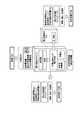
FIG. 2 is a functional block diagram showing a configuration of thepower control system 11 according to the embodiment of the present embodiment, and only functional blocks related to the present embodiment are extracted and shown. In this figure, the same parts as those in thepower control system 10 according to the first embodiment shown in FIG. Thepower control system 11 includes asupplier power system 20, N (N is an integer of 2 or more)customer power systems 30, and acontrol device 41. Thesupplier power system 20 and eachconsumer power system 30 are the same as those in the first embodiment. Hereinafter, the Ncustomer power systems 30 are referred to as customer power systems 30-1 to 30-N, respectively.

供給元電力システム20と需要家電力システム30−1〜30−Nのそれぞれとは、交流系統網51及び直流系統網52により接続される。なお、需要家電力システム30−1〜30−Nの全ての又は一部が、供給元電力システム20と交流系統網51又は直流系統網52のいずれかのみにより接続されてもよい。制御装置41と、供給元電力システム20及び需要家電力システム30−1〜30−Nとは、通信網53を介して通信する。  Thesupplier power system 20 and the customer power systems 30-1 to 30 -N are connected by anAC grid network 51 and aDC grid network 52. Note that all or part of the consumer power systems 30-1 to 30-N may be connected to the supplysource power system 20 only by either theAC grid network 51 or theDC grid network 52. Thecontrol device 41 communicates with thesupplier power system 20 and the customer power systems 30-1 to 30 -N via thecommunication network 53.

制御装置41は、供給元電力システム20及び需要家電力システム30−1〜30−Nの管理及び制御を行う。制御装置41は、情報収集部411、情報記憶部412及び制御部413を備える。情報収集部411は、供給元電力システム20及び需要家電力システム30−1〜30−Nから、各監視項目の状態を表す状態情報を収集する。情報収集部411が、供給元電力システム20及び需要家電力システム30−1〜30−Nのそれぞれから収集する状態情報は、第1の実施形態と同様である。また、情報収集部411は、天候の情報や、売電時の取引価格の情報などを図示しない外部の装置から収集する。  Thecontrol device 41 performs management and control of the supplysource power system 20 and the consumer power systems 30-1 to 30-N. Thecontrol device 41 includes aninformation collection unit 411, an information storage unit 412, and acontrol unit 413. Theinformation collecting unit 411 collects state information representing the state of each monitoring item from the supplysource power system 20 and the customer power systems 30-1 to 30-N. The state information collected by theinformation collection unit 411 from each of the supplysource power system 20 and the customer power systems 30-1 to 30-N is the same as that in the first embodiment. Theinformation collection unit 411 collects weather information, transaction price information at the time of power sale, and the like from an external device (not shown).

情報記憶部412は、情報収集部411が収集した状態情報の履歴であるログデータや、外部の装置から収集した情報の履歴を記憶する。ログデータは、システム識別情報と、システム識別情報により特定される供給元電力システム20又は需要家電力システム30−1〜30−Nのいずれかから収集された状態情報と、状態情報が得られた時刻を示す時刻情報とを対応付けた情報である。  The information storage unit 412 stores log data that is a history of state information collected by theinformation collection unit 411 and a history of information collected from an external device. As for the log data, the system identification information, the state information collected from any of the supplysource power system 20 or the customer power systems 30-1 to 30-N specified by the system identification information, and the state information are obtained. This is information in which time information indicating the time is associated.

制御部413は、情報収集部411が通知を受けた状態情報や、外部の装置から収集した情報、時刻、情報記憶部412に記憶される情報などに基づいて、供給元電力システム20及び需要家電力システム30−1〜30−Nを制御する。制御部413が供給元電力システム20に対して行う制御、及び、個々の需要家電力システム30−1〜30−Nに対して行う制御は、第1の実施形態の制御部403が供給元電力システム20に対して行う制御、及び、需要家電力システム30に対して行う制御と同様である。  Based on the status information notified by theinformation collection unit 411, information collected from an external device, time, information stored in the information storage unit 412 and the like, thecontrol unit 413 and theconsumer electronics system 20 The force systems 30-1 to 30-N are controlled. The control performed by thecontrol unit 413 on the supplysource power system 20 and the control performed on the individual customer power systems 30-1 to 30-N are performed by thecontrol unit 403 of the first embodiment. This is the same as the control performed on thesystem 20 and the control performed on theconsumer power system 30.

例えば、制御装置41の制御部413は、常時に、省エネルギーなどのために、需要家電力システム30−1〜30−Nのうち、1以上の需要家電力システム30−n(nは1以上N以下の整数)に供給元電力システム20が蓄電している電力を供給すると判断する。制御部413は、需要家電力システム30−n以外の1以上の需要家電力システム30−j(j≠n,jは1以上N以下の整数)にはケースB1−1の制御を行い、供給元電力システム20及び需要家電力システム30−nに対しては、以下の(1)〜(3)のいずれの制御を行う。  For example, thecontrol unit 413 of thecontrol device 41 always has one or more customer power systems 30-n (n is 1 or more N) among the customer power systems 30-1 to 30-N for energy saving or the like. It is determined that the power stored by the supplysource power system 20 is supplied to the following integer). Thecontrol unit 413 controls the case B1-1 for one or more customer power systems 30-j (j ≠ n, where j is an integer not less than 1 and not more than N) other than the customer power systems 30-n, and supplies them. Any control of the following (1)-(3) is performed with respect to the formerelectric power system 20 and the consumer electric power system 30-n.

(1)制御部413は、供給元電力システム20から交流により電力供給を行うと判断した場合、供給元電力システム20にケースA2−1の制御を行い、需要家電力システム30−nにケースB2−1の制御を行う。
(2)制御部413は、供給元電力システム20から直流により電力供給を行うと判断した場合、供給元電力システム20にケースA2−2の制御を行い、需要家電力システム30−nにケースB2−2の制御を行う。
(3)制御部413は、供給元電力システム20から交流及び直流により電力供給を行うと判断した場合、供給元電力システム20にケースA2−3の制御を行い、需要家電力システム30−nにケースB2−3の制御を行う。
(1) When thecontrol unit 413 determines that power is supplied from the supplysource power system 20 by alternating current, thecontrol unit 413 controls the supplysource power system 20 in the case A2-1, and controls the customer power system 30-n in the case B2. -1 control is performed.
(2) When thecontrol unit 413 determines that power is supplied from the supplysource power system 20 by direct current, thecontrol unit 413 controls the supplysource power system 20 in case A2-2, and controls the customer power system 30-n in case B2. -2 is performed.
(3) When thecontrol unit 413 determines that power is supplied from the supplysource power system 20 by alternating current and direct current, thecontrol unit 413 controls the supplysource power system 20 in Case A2-3 to provide power to the consumer power system 30-n. Case B2-3 is controlled.

なお、交流系統網51が一般送配電事業者の電力網である場合、(1)又は(3)の制御を行う際、制御部413は、交流系統網51に対して、需要家電力システム30−nへの電力供給のルートを、商用電力の供給ルートから、供給元電力システム20からの電力の供給ルートへ切替えるよう指示する。  In addition, when theAC grid network 51 is a power transmission / distribution company power grid, when performing the control (1) or (3), thecontrol unit 413 controls theAC grid network 51 with the consumer power system 30-. The power supply route to n is instructed to be switched from the commercial power supply route to the power supply route from the supplysource power system 20.

また、交流系統網51が一般送配電事業者(商用電力)の電力網ではない場合、(1)又は(3)の制御を行う際、制御部413は、需要家電力システム30−nの受電装置311に対して、供給元電力システム20からの電力の供給ルートである交流系統網51からの受電を指示する。需要家電力システム30の受電装置311は、制御装置41からの指示に従って、一般送配電事業者(商用電力)の電力網からの受電を、交流系統網51からの受電に切替える。  Further, when theAC grid network 51 is not a power transmission / distribution company (commercial power) power network, thecontrol unit 413 controls the power receiving device of the consumer power system 30-n when performing the control of (1) or (3). 311 is instructed to receive power from theAC grid network 51, which is a power supply route from the supplysource power system 20. Thepower reception device 311 of theconsumer power system 30 switches the power reception from the power transmission / distribution company (commercial power) to the power reception from theAC grid network 51 in accordance with an instruction from thecontrol device 41.

本実施形態では、交流のみ、直流のみ、又は、交流及び直流で供給元電力システム20からの電力供給を受ける需要家電力システム30−nが混在する場合がある。この場合、制御部413は、供給元電力システム20にはケースA2−3の制御を行い、交流のみで電力供給を受ける需要家電力システム30−nにはケースB2−1の制御を、直流のみで電力供給を受ける需要家電力システム30−nにはケースB2−2の制御を、交流及び直流で電力供給を受ける需要家電力システム30−nにはケースB2−3の制御を行う。  In the present embodiment, there may be a mixture of consumer power systems 30-n that receive power supply from the powersource power system 20 using only alternating current, only direct current, or alternating current and direct current. In this case, thecontrol unit 413 controls thesupply power system 20 in case A2-3, controls the case B2-1 in the consumer power system 30-n that receives power supply only through alternating current, and controls only direct current. The control of case B2-2 is performed for the consumer power system 30-n that receives power supply, and the control of case B2-3 is performed for the consumer power system 30-n that receives power supply by alternating current and direct current.

また、例えば、制御装置41の制御部413は、需要家電力システム30−1〜30−Nのうち、1以上の需要家電力システム30−n(nは1以上N以下の整数)に商用電力への供給が停止し、需要家電力システム30−n以外の1以上の需要家電力システム30−j(j≠n,jは1以上N以下の整数)には商用電力への供給が継続していることを検出する。制御部413は、需要家電力システム30−jに対しては、ケースB1−1の制御を行い、供給元電力システム20及び需要家電力システム30−nには以下の(1)〜(3)のいずれかの制御を行う。  Moreover, for example, thecontrol unit 413 of thecontrol device 41 supplies commercial power to one or more customer power systems 30-n (n is an integer of 1 to N) among the customer power systems 30-1 to 30-N. Supply to commercial power is continued in one or more consumer power systems 30-j (j ≠ n, where j is an integer between 1 and N) other than the consumer power system 30-n. Detect that Thecontrol unit 413 controls the case B1-1 for the consumer power system 30-j, and the following (1) to (3) for thesupplier power system 20 and the consumer power system 30-n. Do one of the controls.

(1)制御部413は、供給元電力システム20から交流により電力供給を行うと判断した場合、供給元電力システム20にケースA3−1の制御を行い、需要家電力システム30−nにケースB3−1の制御を行う。
(2)制御部413は、供給元電力システム20から直流により電力供給を行うと判断した場合、供給元電力システム20にケースA3−2の制御を行い、需要家電力システム30−nにケースB3−2の制御を行う。
(3)制御部413は、供給元電力システム20から交流及び直流により電力供給を行うと判断した場合、供給元電力システム20にケースA3−3の制御を行い、需要家電力システム30−nにケースB3−3の制御を行う。
(1) When thecontrol unit 413 determines that power is supplied from the supplysource power system 20 by alternating current, thecontrol unit 413 controls the supplysource power system 20 in case A3-1, and controls the consumer power system 30-n in case B3. -1 control is performed.
(2) When thecontrol unit 413 determines that power is supplied from the supplysource power system 20 by direct current, thecontrol unit 413 controls the supplysource power system 20 in Case A3-2, and controls the customer power system 30-n in case B3. -2 is performed.
(3) When thecontrol unit 413 determines that power is supplied from the supplysource power system 20 by alternating current and direct current, thecontrol unit 413 controls the supplysource power system 20 in Case A3-3 to provide power to the consumer power system 30-n. The case B3-3 is controlled.

本実施形態では、上述した常時の場合と同様に、非常時においても、交流のみ、直流のみ、又は、交流及び直流で供給元電力システム20からの電力供給を受ける需要家電力システム30−nが混在する場合がある。この場合、制御部413は、供給元電力システム20にはケースA3−3の制御を行い、交流のみで電力供給を受ける需要家電力システム30−nにはケースB3−1の制御を、直流のみで電力供給を受ける需要家電力システム30−nにはケースB3−2の制御を、交流及び直流で電力供給を受ける需要家電力システム30−nにはケースB3−3の制御を行う。以下に具体的な制御の例を説明する。  In the present embodiment, as in the normal case described above, even in an emergency, the consumer power system 30-n that receives power supply from the supplysource power system 20 only in alternating current, only direct current, or alternating current and direct current is provided. May be mixed. In this case, thecontrol unit 413 controls thesupply power system 20 in case A3-3, controls the case B3-1 in the consumer power system 30-n that receives power supply only through alternating current, and controls only direct current. The control of case B3-2 is performed for the consumer power system 30-n that receives power supply in step B3-3, and the control of case B3-3 is performed for the consumer power system 30-n that receives power supply by alternating current and direct current. A specific example of control will be described below.

制御部413は、需要家電力システム30−1〜30−i(iは2以上N−1以下の整数)への商用電力の供給が停止したことを検出する。需要家電力システム30−1〜30−iは、交流系統網51及び直流系統網52で供給元電力システム20と接続される。この場合、制御部413は、供給元電力システム20にケースA3−1の制御を、需要家電力システム30−1〜30−iにケースB3−1の制御を、需要家電力システム30−(i+1)〜30−NにケースB1−1の制御を行う。そして、制御部413は、需要家電力システム30−1〜30−iのうち、交流電力を受電できなかった需要家電力システム30に対してはケースB3−2の制御を開始し、供給元電力システム20に対してはケースA3−3の制御を開始する。  Thecontrol unit 413 detects that the supply of commercial power to the consumer power systems 30-1 to 30-i (i is an integer of 2 or more and N-1 or less) is stopped. The consumer power systems 30-1 to 30-i are connected to the supplysource power system 20 by theAC grid network 51 and theDC grid network 52. In this case, thecontrol unit 413 controls thesupply power system 20 in case A3-1, the consumer power systems 30-1 to 30-i in case B3-1, and the consumer power system 30- (i + 1). ) To 30-N, the case B1-1 is controlled. And controlpart 413 starts control of case B3-2 to consumerelectric power system 30 which was not able to receive exchange electric power among consumer electric power systems 30-1 to 30-i, and supply source electric power. Control of the case A3-3 is started for thesystem 20.

また、需要家電力システム30−1〜30−iの中には、交流系統網51のみ、又は、直流系統網52のみで供給元電力システム20と接続される需要家電力システム30が含まれ得る。この場合、制御部413は、需要家電力システム30−1〜30−iのうち、交流系統網51及び直流系統網52で供給元電力システム20と接続される需要家電力システム30に対してはケースB3−1又はB3−2又はB3−3の制御を行い、交流系統網51のみで供給元電力システム20と接続される需要家電力システム30に対してはケースB3−1の制御を行い、直流系統網52のみで供給元電力システム20と接続される需要家電力システム30に対してはケースB3−2の制御を行う。制御部413は、供給元電力システム20に対して、ケースA3−3の制御を行う。  The consumer power systems 30-1 to 30-i may include theconsumer power system 30 connected to the supplysource power system 20 only by theAC grid network 51 or only by theDC grid network 52. . In this case, thecontrol part 413 is with respect to the consumerelectric power system 30 connected with the supply sourceelectric power system 20 by the alternatingcurrent system network 51 and the directcurrent system network 52 among the consumer electric power systems 30-1 to 30-i. The case B3-1 or B3-2 or B3-3 is controlled, and the case B3-1 is controlled for thecustomer power system 30 connected to the supplysource power system 20 only by theAC grid network 51. Case B3-2 is controlled for thecustomer power system 30 connected to the supplysource power system 20 only by theDC system network 52. Thecontrol unit 413 controls thesupply power system 20 in case A3-3.

本実施形態によれば、複数の電力需要家が予備電源を共用するため、低コストで一つの電力供給元が有する予備電源から、複数の電力需要家に対して電力供給を行うことができる。  According to this embodiment, since a plurality of power consumers share a standby power source, it is possible to supply power to the plurality of power consumers from a standby power source possessed by one power supply source at a low cost.
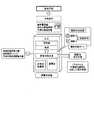
[第3の実施形態]
本実施形態では、複数の電力供給元がそれぞれ、1以上の電力需要家と接続される。
図3は、本実施形態の実施形態による電力制御システム12の構成を示す機能ブロック図であり、本実施形態と関係する機能ブロックのみを抽出して示してある。同図において、図1に示す第1の実施形態による電力制御システム10と同一の部分には同一の符号を付し、その説明を省略する。電力制御システム12は、複数の供給元電力システム22と、各供給元電力システム22と接続される1以上の需要家電力システム30と、制御装置42とを有する。各需要家電力システム30はそれぞれ、第1の実施形態と同様である。以下では、M個の供給元電力システム22をそれぞれ、供給元電力システム22−1〜22−Mと記載し、供給元電力システム22−m(mは1以上M以下の整数)と接続されるN個(Nは1以上の整数)の需要家電力システム30をそれぞれ、需要家電力システム30−m−1〜30−m−Nと記載する。また、需要家電力システム30−m−1〜30−m−Nを総称して需要家電力システム30−mとも記載する。
[Third Embodiment]
In the present embodiment, each of a plurality of power supply sources is connected to one or more power consumers.
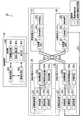
FIG. 3 is a functional block diagram showing a configuration of thepower control system 12 according to the embodiment of the present embodiment, and only functional blocks related to the present embodiment are extracted and shown. In this figure, the same parts as those in thepower control system 10 according to the first embodiment shown in FIG. Thepower control system 12 includes a plurality ofsupply power systems 22, one or moreconsumer power systems 30 connected to eachsupply power system 22, and acontrol device 42. Eachconsumer power system 30 is the same as that of the first embodiment. Hereinafter, the M supplysource power systems 22 are referred to as supply source power systems 22-1 to 22-M, and are connected to the supply source power systems 22-m (m is an integer of 1 to M). Nm (Nm is an integer equal to or greater than 1)customer power systems 30 will be referred to as customer power systems 30-m-1 to 30-m-Nm , respectively. Further, also referred to as demand consumer electronics power system 30-m collectively demand consumer electronics power system 30-m-1~30-m- N m.

供給元電力システム22−mと需要家電力システム30−mのそれぞれとは、交流系統網51及び直流系統網52により接続される。なお、供給元電力システム22−mと一部又は全ての需要家電力システム30−mとが、交流系統網51のみ又は直流系統網52のみにより接続されてもよい。制御装置42と、供給元電力システム22及び需要家電力システム30とは、通信網53を介して通信する。  The supplier power system 22-m and the customer power system 30-m are connected by anAC grid network 51 and aDC grid network 52. The supply source power system 22-m and a part or all of the customer power systems 30-m may be connected only by theAC grid network 51 or only by theDC grid network 52. Thecontrol device 42 communicates with the supplysource power system 22 and thecustomer power system 30 via thecommunication network 53.

供給元電力システム22が、第1の実施形態の供給元電力システム20と異なる点は、交流潮流制御装置211及び直流潮流制御装置216に代えて、交流潮流制御装置211a及び直流潮流制御装置216aを備える点である。交流潮流制御装置211aは、他の1以上の供給元電力システム22の交流潮流制御装置211aと交流系統網54により接続される。交流潮流制御装置211aは、第1の実施形態の交流潮流制御装置211と同様に動作し、さらに、交流系統網54からの交流電力の受電と交流系統網54への交流電力の送電とを行う。直流潮流制御装置216aは、他の1以上の供給元電力システム22の直流潮流制御装置216aと直流系統網55により接続される。直流潮流制御装置216aは、第1の実施形態の直流潮流制御装置216と同様に動作し、さらに、直流系統網55からの直流電力の受電と直流系統網55への直流電力の送電とを行う。  Thesource power system 22 is different from thesource power system 20 of the first embodiment in that an AC powerflow control device 211a and a DC powerflow control device 216a are used instead of the AC powerflow control device 211 and the DC powerflow control device 216. It is a point to prepare. The AC powerflow control device 211a is connected to the AC powerflow control device 211a of one or more otherpower supply systems 22 by theAC system network 54. The AC powerflow control device 211a operates in the same manner as the AC powerflow control device 211 of the first embodiment, and further receives AC power from theAC grid network 54 and transmits AC power to theAC grid network 54. . The DC powerflow control device 216a is connected to the DC powerflow control device 216a of the other one or more supplysource power systems 22 by theDC network 55. The DC powerflow control device 216a operates in the same manner as the DC powerflow control device 216 of the first embodiment, and further receives DC power from theDC network 55 and transmits DC power to theDC network 55. .

この構成により、供給元電力システム22−mは、非常時に自システムのみでは需要家電力システム30−mに対して供給する電力が不足する場合に、1以上の他の供給元電力システム22−k(k≠m,kは1以上M以下の整数)から交流系統網54と直流系統網55の一方又は両方を介して予備電源による電力(蓄電池203に蓄電されている電力や非常用発電機202により発電した電力)の供給を受ける。また、常時に供給元電力システム22間において蓄電電力を融通する。  With this configuration, in the event of an emergency, the supply source power system 22-m has one or more other supply source power systems 22-k when the power supply to the consumer power system 30-m is insufficient by itself. (K ≠ m, k is an integer from 1 to M) to the power from the standby power source via one or both of theAC grid network 54 and the DC grid network 55 (the power stored in thestorage battery 203 and theemergency generator 202 The power generated by In addition, the stored power is interchanged between the supplysource power systems 22 at all times.

なお、一部又は全ての供給元電力システム22は、他の供給元電力システム22と、交流系統網54又は直流系統網55のいずれかのみで接続されてもよい。また、一部の又は全ての供給元電力システム22は、他の供給元電力システム22から予備電源による電力を受けない構成としてもよい。  Note that some or all of the supplysource power systems 22 may be connected to other supplysource power systems 22 only by either theAC grid network 54 or theDC grid network 55. Also, some or all of the supplysource power systems 22 may be configured not to receive power from the standby power supply from other supplysource power systems 22.

制御装置42は、供給元電力システム22−1〜22−M及び需要家電力システム30−1−1〜30−M−Nの管理及び制御を行う。制御装置42は、情報収集部421、情報記憶部422及び制御部423を備える。情報収集部421は、供給元電力システム22−1〜22−M及び需要家電力システム30−1−1〜30−M−Nから、各監視項目の状態を表す状態情報を収集する。情報収集部421が、供給元電力システム22−1〜22−M及び需要家電力システム30−1−1〜30−M−Nのそれぞれから収集する状態情報は、第1の実施形態と同様である。また、情報収集部421は、天候の情報や、売電時の取引価格の情報などを図示しない外部の装置から収集する。Controller 42 performs management and control of the supply source power system 22-1 to 22-M and demand consumer electronics power system30-1-1~30-M-N M. Thecontrol device 42 includes aninformation collection unit 421, aninformation storage unit 422, and acontrol unit 423.Information collection unit 421 from the supply source power system 22-1 to 22-M and demand consumer electronics power system30-1-1~30-M-N M, collects the state information indicating the state of each monitored item.Information collection unit 421, the state information collected from each of the supply source power system 22-1 to 22-M and demand consumer electronics power system30-1-1~30-M-N M, as in the first embodiment It is. Theinformation collecting unit 421 collects weather information, transaction price information at the time of power sale, and the like from an external device (not shown).

情報記憶部422は、情報収集部421が収集した状態情報の履歴であるログデータや、外部の装置から収集した情報の履歴を記憶する。ログデータは、システム識別情報と、システム識別情報により特定される供給元電力システム22−1〜22−M又は需要家電力システム30−1−1〜30−M−Nのいずれかから収集された状態情報と、状態情報が得られた時刻を示す時刻情報とを対応付けた情報である。Theinformation storage unit 422 stores log data that is a history of state information collected by theinformation collection unit 421 and a history of information collected from an external device. The log data is collected from the system identification information and any of the power supply system 22-1 to 22-M or the customer power system 30-1-1-1 to 30-M-M specified by the system identification information. The state information is associated with time information indicating the time when the state information is obtained.

制御部423は、情報収集部421が通知を受けた状態情報や、外部の装置から収集した情報、時刻、情報記憶部422に記憶される情報などに基づいて、供給元電力システム22−1〜22−M及び需要家電力システム30−1−1〜30−M−Nを制御する。制御部423が、供給元電力システム22−m及び需要家電力システム30−m−1〜30−m−Nの組に対して行う制御は、第2の実施形態と同様の制御を含む。さらに、制御部423は、非常時に、供給元電力システム22−mから需要家電力システム30−mに対して供給する電力が不足する場合に、供給元電力システム22−mへ電力を融通する他の供給元電力システム22−k、融通する電力量、交流系統網54と直流系統網55のいずれを用いるかを決定し、供給元電力システム22−kに指示する。Based on the status information notified by theinformation collection unit 421, information collected from an external device, time, information stored in theinformation storage unit 422, and the like, thecontrol unit 423 supplies the power supply system 22-1 to 2-1. 22-M and consumer power systems 30-1-1-1 to 30-MM are controlled.Control unit 423, the control performed on the set of the supply source power system 22-m and demand consumer electronics power system 30-m-1~30-m- N m comprises a control similar to the second embodiment. Further, thecontrol unit 423, in the event of an emergency, supplies power to the supplier power system 22-m when the power supplied from the supplier power system 22-m to the consumer power system 30-m is insufficient. Supply power system 22-k, the amount of power to be accommodated, and whether to useAC network 54 orDC system network 55 is determined, and the power supply system 22-k is instructed.

以下に、表3に示すケースについて、制御部423の制御に基づく供給元電力システム22の動作例を説明する。  Below, the operation example of thesource power system 22 based on control of thecontrol part 423 is demonstrated about the case shown in Table 3. FIG.

Figure 0006431580
Figure 0006431580

<ケースA4−1:非常時に供給元電力システム22−mが交流で需要家電力システム30−mに電力を供給している場合に、他の供給元電力システム22−kが交流で電力を融通>
制御装置42の制御部423は、第1の実施形態のケースA3−1の制御を供給元電力システム22−mに行っており、供給元電力システム22−mから、需要家電力システム30−mに供給する電力が不足しているとする。制御部423は、供給元電力システム22−kから供給元電力システム22−mに交流で電力を融通する場合、供給元電力システム22−kに対して、以下の制御を行う。
<Case A4-1: When the power source power system 22-m supplies power to the customer power system 30-m in an emergency in the event of an emergency, the other power source power system 22-k interchanges power with the AC >
Thecontrol unit 423 of thecontrol device 42 performs control of the case A3-1 of the first embodiment to the supply source power system 22-m, and from the supply source power system 22-m to the consumer power system 30-m. Suppose that there is not enough power to supply Thecontrol unit 423 performs the following control on the supply source power system 22-k when ac power is interchanged from the supply source power system 22-k to the supply source power system 22-m.

(1)交流潮流制御装置211aに交流系統網54への送電及び電圧を指示。
(2)発電機201の発電又は発電停止を指示。発電機201による発電量が制御可能な場合、発電の指示に併せて、発電量も指示する。
(3)非常用発電機202の発電及び発電量が制御可能な場合はその発電量と、蓄電池203の放電及び放電量が制御可能な場合はその放電量との少なくとも一方を指示。
(1) Instructing the AC powerflow control device 211a to transmit power to theAC grid 54 and voltage.
(2) Instructing thegenerator 201 to generate power or stop generating power. When the power generation amount by thegenerator 201 is controllable, the power generation amount is also instructed together with the power generation instruction.
(3) When the power generation and power generation amount of theemergency generator 202 are controllable, the power generation amount is instructed, and when the discharge and discharge amount of thestorage battery 203 are controllable, at least one of the discharge amount is instructed.

さらに、制御装置42の制御部423は、供給元電力システム22−mに対して、交流潮流制御装置211aにおける交流系統網54からの受電を指示する。  Furthermore, thecontrol unit 423 of thecontrol device 42 instructs the supply source power system 22-m to receive power from theAC grid network 54 in the AC powerflow control device 211a.

供給元電力システム22−kは、以下のように動作する。
蓄電池203の放電が指示された場合、直流電源装置214は、蓄電池203が放電した直流電力を配電装置215に供給し、残りの電力を交流に変換して配電装置213に送電する。また、発電機201及び非常用発電機202は、発電が指示された場合、発電した電力を配電装置213に送電する。配電装置213は、発電機201、非常用発電機202及び直流電源装置214から受電した電力を負荷221に供給し、残りの電力を受電装置212に送電する。受電装置212は、配電装置213から受電した電力を交流潮流制御装置211aに出力し、交流潮流制御装置211aは、受電装置212から受電した電力を交流系統網54に送電する。供給元電力システム22−mの交流潮流制御装置211aは、交流系統網54を介して供給元電力システム22−kから交流電力を受電し、受電装置212から受電した電力と併せて交流系統網51に送電する。
The supplier power system 22-k operates as follows.
When the discharge of thestorage battery 203 is instructed, the DCpower supply device 214 supplies the DC power discharged by thestorage battery 203 to thepower distribution device 215, converts the remaining power to AC, and transmits the power to thepower distribution device 213. Thegenerator 201 and theemergency generator 202 transmit the generated power to thepower distribution device 213 when power generation is instructed. Thepower distribution device 213 supplies the power received from thegenerator 201, theemergency generator 202 and the DCpower supply device 214 to theload 221, and transmits the remaining power to thepower reception device 212. Thepower receiving device 212 outputs the power received from thepower distribution device 213 to the AC powerflow control device 211a, and the AC powerflow control device 211a transmits the power received from thepower receiving device 212 to theAC grid network 54. The AC powerflow control device 211a of the supply source power system 22-m receives AC power from the supply source power system 22-k via theAC grid network 54, and is combined with the power received from thepower reception device 212 in theAC grid network 51. Power to.

<ケースA4−2:非常時に供給元電力システム22−mが交流で需要家電力システム30−mに電力を供給している場合に、他の供給元電力システム22−kが直流で電力を融通>
制御装置42の制御部423は、第1の実施形態のケースA3−1の制御を供給元電力システム22−mに行っているときに、供給元電力システム22−kから供給元電力システム22−mに直流で電力を融通するよう制御する。この場合、制御部423は、供給元電力システム22−kに対して、以下の制御を行う。
<Case A4-2: When the supplier power system 22-m supplies power to the customer power system 30-m in an emergency, the other supplier power system 22-k exchanges power with the DC >
Thecontrol unit 423 of thecontrol device 42 performs the control of the case A3-1 of the first embodiment on the supply source power system 22-m to the supply source power system 22-k. It controls so that electric power can be accommodated in m by direct current. In this case, thecontrol unit 423 performs the following control on the supply source power system 22-k.

(1)発電機201の発電又は発電停止の指示。発電機201による発電量が制御可能な場合、発電の指示に併せて、発電量も指示する。
(2)非常用発電機202の発電及び発電量が制御可能な場合はその発電量と、蓄電池203の放電及び放電量が制御可能な場合はその放電量との少なくとも一方を指示。
(3)直流潮流制御装置216aに直流系統網55への送電及び電圧を指示。
(1) Instruction for power generation bygenerator 201 or power generation stop. When the power generation amount by thegenerator 201 is controllable, the power generation amount is also instructed together with the power generation instruction.
(2) Instructing at least one of the power generation amount when theemergency generator 202 can control the power generation amount and the discharge amount when the discharge and discharge amount of thestorage battery 203 are controllable.
(3) Instructing the DC powerflow control device 216a to transmit power to theDC network 55 and voltage.

さらに、制御装置42の制御部423は、供給元電力システム22−mに対して、直流潮流制御装置216aにおける直流系統網55からの受電を指示する。  Furthermore, thecontrol unit 423 of thecontrol device 42 instructs the supply source power system 22-m to receive power from theDC network 55 in the DC powerflow control device 216a.

供給元電力システム22−kは、以下のように動作する。
発電機201及び非常用発電機202は、制御装置42から発電が指示された場合、発電した電力を配電装置213に送電する。直流電源装置214は、制御装置42から蓄電池203の放電が指示された場合、蓄電池203が放電した電力を受電する。
The supplier power system 22-k operates as follows.
Thepower generator 201 and theemergency power generator 202 transmit the generated power to thepower distribution device 213 when power generation is instructed from thecontrol device 42. TheDC power supply 214 receives the electric power discharged from thestorage battery 203 when thecontroller 42 instructs the discharge of thestorage battery 203.

交流潮流制御装置211aは、交流系統網51から受電した商用電力を受電装置212に送電する。受電装置212は、交流潮流制御装置211aから受電した商用電力を配電装置213へ送電する。配電装置213は、受電装置212からの商用電力と、発電機201、非常用発電機202それぞれの発電電力を受電し、直流電源装置214及び負荷221に出力する。直流電源装置214は、蓄電池203が放電した電力、及び、配電装置213から受電し、直流に変換した電力を、配電装置215に出力する。配電装置215は、直流電源装置214から受電した直流電力を負荷222に送電し、残りの電力を直流潮流制御装置216aに送電する。直流潮流制御装置216aは、配電装置215から受電した直流電力を、直流系統網55に送電する。  The AC powerflow control device 211 a transmits the commercial power received from theAC grid network 51 to thepower receiving device 212. Thepower receiving device 212 transmits the commercial power received from the AC powerflow control device 211 a to thepower distribution device 213. Thepower distribution device 213 receives the commercial power from thepower receiving device 212 and the power generated by each of thegenerator 201 and theemergency generator 202 and outputs them to the DCpower supply device 214 and theload 221. The DCpower supply device 214 outputs the power discharged from thestorage battery 203 and the power received from thepower distribution device 213 and converted into direct current to thepower distribution device 215. Thepower distribution device 215 transmits the DC power received from the DCpower supply device 214 to theload 222, and transmits the remaining power to the DC powerflow control device 216a. The DC powerflow control device 216 a transmits the DC power received from thepower distribution device 215 to theDC network 55.

供給元電力システム22−mの直流潮流制御装置216aは、直流系統網55を介して、供給元電力システム22−kから直流電力を受電し、配電装置215に送電する。配電装置215は、直流潮流制御装置216aから受電した電力を負荷222及び直流電源装置214に送電する。直流電源装置214は、蓄電池203及び配電装置215から受電した電力を交流に変換し、配電装置213に送電する。以降の供給元電力システム22−mの動作は、ケースA3−1と同様である。  The DC powerflow control device 216 a of the supply source power system 22-m receives DC power from the supply source power system 22-k via theDC system network 55 and transmits it to thepower distribution device 215. Thepower distribution device 215 transmits the power received from the DC powerflow control device 216 a to theload 222 and the DCpower supply device 214. The DCpower supply device 214 converts the power received from thestorage battery 203 and thepower distribution device 215 into an alternating current, and transmits the alternating current to thepower distribution device 213. The subsequent operation of the supplier power system 22-m is the same as in the case A3-1.

<ケースA4−3:非常時に供給元電力システム22−mが交流で需要家電力システム30−mに電力を供給している場合に、他の供給元電力システム22−kが交流及び直流で電力を融通>
制御装置42の制御部423は、第1の実施形態のケースA3−1の制御を供給元電力システム22−mに行っているときに、供給元電力システム22−kから供給元電力システム22−mに交流及び直流で電力を融通するよう制御する。この場合、制御部423は、供給元電力システム22−kに対して、以下の制御を行う。
<Case A4-3: When the supplier power system 22-m supplies power to the customer power system 30-m in an emergency in the event of an emergency, the other supplier power system 22-k uses AC and DC power >
Thecontrol unit 423 of thecontrol device 42 performs the control of the case A3-1 of the first embodiment on the supply source power system 22-m to the supply source power system 22-k. It controls so that electric power can be accommodated in m by alternating current and direct current. In this case, thecontrol unit 423 performs the following control on the supply source power system 22-k.

(1)交流潮流制御装置211aに交流系統網54への送電及び電圧を指示。
(2)発電機201の発電又は発電停止を指示。発電機201による発電量が制御可能な場合、発電の指示に併せて、発電量も指示する。
(3)非常用発電機202の発電及び発電量が制御可能な場合はその発電量と、蓄電池203の放電及び放電量が制御可能な場合はその放電量との少なくとも一方を指示。
(4)直流潮流制御装置216aに直流系統網55への送電及び電圧を指示。
(1) Instructing the AC powerflow control device 211a to transmit power to theAC grid 54 and voltage.
(2) Instructing thegenerator 201 to generate power or stop generating power. When the power generation amount by thegenerator 201 is controllable, the power generation amount is also instructed together with the power generation instruction.
(3) When the power generation and power generation amount of theemergency generator 202 are controllable, the power generation amount is instructed, and when the discharge and discharge amount of thestorage battery 203 are controllable, at least one of the discharge amount is instructed.
(4) Instructing the DC powerflow control device 216a to transmit power to theDC network 55 and voltage.

さらに、制御装置42の制御部423は、供給元電力システム22−mに対して、交流潮流制御装置211aにおける交流系統網54からの受電と、直流潮流制御装置216aにおける直流系統網55からの受電を指示する。  Furthermore, thecontrol unit 423 of thecontrol device 42 receives power from theAC grid network 54 in the AC powerflow control device 211a and power reception from theDC power network 55 in the DC powerflow control device 216a for the supply power system 22-m. Instruct.

供給元電力システム22−kは、以下のように動作する。
発電機201及び非常用発電機202は、制御装置42から発電が指示された場合、発電した電力を配電装置213に送電する。配電装置213は、発電機201及び非常用発電機202から受電した電力を負荷221に供給し、残りの電力を、受電装置212及び直流電源装置214に送電する。受電装置212は、配電装置213から受電した電力を交流潮流制御装置211aに出力し、交流潮流制御装置211aは、受電装置212から受電した電力を交流系統網54に送電する。
The supplier power system 22-k operates as follows.
Thepower generator 201 and theemergency power generator 202 transmit the generated power to thepower distribution device 213 when power generation is instructed from thecontrol device 42. Thepower distribution apparatus 213 supplies the power received from thegenerator 201 and theemergency generator 202 to theload 221 and transmits the remaining power to thepower reception apparatus 212 and the DCpower supply apparatus 214. Thepower receiving device 212 outputs the power received from thepower distribution device 213 to the AC powerflow control device 211a, and the AC powerflow control device 211a transmits the power received from thepower receiving device 212 to theAC grid network 54.

直流電源装置214は、配電装置213から受電した電力を交流から直流に変換し、制御装置42から蓄電池203の放電が指示された場合はさらに、蓄電池203が放電した直流電力を受電する。直流電源装置214は、配電装置215に直流電力を送電する。配電装置215は、直流電源装置214から受電した直流電力を負荷222に送電し、残りの電力を直流潮流制御装置216aに送電する。直流潮流制御装置216aは、配電装置215から受電した直流電力を、直流系統網55に送電する。  The DCpower supply device 214 converts the power received from thepower distribution device 213 from AC to DC, and further receives the DC power discharged from thestorage battery 203 when thecontrol device 42 is instructed to discharge thestorage battery 203. The DCpower supply device 214 transmits DC power to thepower distribution device 215. Thepower distribution device 215 transmits the DC power received from the DCpower supply device 214 to theload 222, and transmits the remaining power to the DC powerflow control device 216a. The DC powerflow control device 216 a transmits the DC power received from thepower distribution device 215 to theDC network 55.

なお、蓄電池203から放電された電力量が、負荷222の消費電力量と、直流により需要家電力システム30へ供給する電力量との合計よりも多い場合、直流電源装置214は、配電装置215へ送電した残りの電力を交流に変換して配電装置213へ送電する。配電装置213は、発電機201、非常用発電機202及び直流電源装置214から受電した電力を負荷221に供給し、残りの電力を受電装置212に送電する。  Note that when the amount of power discharged from thestorage battery 203 is greater than the sum of the amount of power consumed by theload 222 and the amount of power supplied to theconsumer power system 30 by direct current, the direct-currentpower supply device 214 passes to thepower distribution device 215. The remaining transmitted power is converted into alternating current and transmitted to thepower distribution apparatus 213. Thepower distribution device 213 supplies the power received from thegenerator 201, theemergency generator 202 and the DCpower supply device 214 to theload 221, and transmits the remaining power to thepower reception device 212.

供給元電力システム22−mの直流潮流制御装置216aは、直流系統網55を介して、供給元電力システム22−kから直流電力を受電し、配電装置215に送電する。配電装置215は、直流潮流制御装置216aから受電した電力を電力供給対象の負荷222及び直流電源装置214に送電する。直流電源装置214は、蓄電池203及び配電装置215から受電した電力を交流に変換し、配電装置213に送電する。配電装置213は、発電機201、非常用発電機202及び直流電源装置214から受電した電力を電力供給対象の負荷221に供給し、残りの電力を受電装置212に送電する。受電装置212は、配電装置213から受電した電力を交流潮流制御装置211aに出力する。交流潮流制御装置211aは、受電装置212から受電した電力と、交流系統網54を介して供給元電力システム22−kから受電した交流電力とを、交流系統網51に送電する。  The DC powerflow control device 216 a of the supply source power system 22-m receives DC power from the supply source power system 22-k via theDC system network 55 and transmits it to thepower distribution device 215. Thepower distribution device 215 transmits the power received from the DC powerflow control device 216a to theload 222 and the DCpower supply device 214 that are power supply targets. The DCpower supply device 214 converts the power received from thestorage battery 203 and thepower distribution device 215 into an alternating current, and transmits the alternating current to thepower distribution device 213. Thepower distribution device 213 supplies the power received from thepower generator 201, theemergency power generator 202, and the DCpower supply device 214 to theload 221 to be supplied with power, and transmits the remaining power to thepower receiving device 212. Thepower receiving device 212 outputs the power received from thepower distribution device 213 to the AC powerflow control device 211a. The AC powerflow control device 211 a transmits the power received from thepower receiving device 212 and the AC power received from the supply source power system 22-k via theAC grid network 54 to theAC grid network 51.

<ケースA4−4:非常時に供給元電力システム22−mが直流で需要家電力システム30−mに電力を供給している場合に、他の供給元電力システム22−kが交流で電力を融通>
制御装置42の制御部423は、第1の実施形態のケースA3−2の制御を供給元電力システム22−mに行っており、供給元電力システム22−mから、需要家電力システム30−mに供給する電力が不足しているとする。制御部423は、供給元電力システム22−kから供給元電力システム22−mに交流で電力を融通する場合、供給元電力システム22−kに対して、ケースA4−1と同様の制御を行い、供給元電力システム22−mに対して、交流潮流制御装置211aにおける交流系統網54からの受電を指示する。これにより、供給元電力システム22−mは、以下の動作以外は、ケースA3−2と同様に動作する。すなわち、交流潮流制御装置211aは、交流系統網51から受電した交流電力と、交流系統網54から受電した交流電力とを合わせて受電装置212に出力する。
<Case A4-4: When the supplier power system 22-m supplies power to the customer power system 30-m in a direct current in an emergency, the other supplier power system 22-k exchanges power with an AC >
Thecontrol unit 423 of thecontrol device 42 performs control of the case A3-2 of the first embodiment to the supply source power system 22-m, and the supply source power system 22-m to the consumer power system 30-m. Suppose that there is not enough power to supply Thecontrol unit 423 performs the same control as the case A4-1 on the supply source power system 22-k when power is exchanged from the supply source power system 22-k to the supply source power system 22-m by alternating current. The power supply system 22-m is instructed to receive power from theAC network 54 in the AC powerflow control device 211a. Thereby, supply electric power system 22-m operate | moves similarly to case A3-2 except the following operation | movement. That is, the AC powerflow control device 211 a outputs the AC power received from theAC grid network 51 and the AC power received from theAC grid network 54 to thepower receiving device 212.

<ケースA4−5:非常時に供給元電力システム22−mが直流で需要家電力システム30−mに電力を供給している場合に、他の供給元電力システム22−kが直流で電力を融通>
制御装置42の制御部423は、第1の実施形態のケースA3−2の制御を行っている供給元電力システム22−mに供給元電力システム22−kから直流で電力を融通するよう制御する。この場合、制御部423は、供給元電力システム22−kに対して、ケースA4−2と同様の指示を行い、供給元電力システム22−mに対して、直流潮流制御装置216aにおける直流系統網55からの受電を指示する。供給元電力システム22−mは、以下の動作以外は、ケースA3−2と同様に動作する。すなわち、供給元電力システム22−mの直流潮流制御装置216aは、配電装置215から受電した直流電力と、直流系統網55を介して供給元電力システム22−kから受電した直流電力とを合わせて直流系統網52に送電する。
<Case A4-5: When the supplier power system 22-m supplies power to the customer power system 30-m in a direct current in an emergency, the other supplier power system 22-k exchanges power with the direct current >
Thecontrol unit 423 of thecontrol device 42 controls the supply source power system 22-m performing the control of the case A3-2 of the first embodiment so as to accommodate power from the supply source power system 22-k with direct current. . In this case, thecontrol unit 423 instructs the supply power system 22-k in the same manner as in case A4-2, and directs the supply power system 22-m to the DC power network in the DC powerflow control device 216a. Instruct to receive power from 55. The supplier power system 22-m operates in the same manner as in the case A3-2 except for the following operations. That is, the DC powerflow control device 216a of the supply source power system 22-m combines the DC power received from thepower distribution device 215 and the DC power received from the supply source power system 22-k via theDC system network 55. Power is transmitted to theDC network 52.

<ケースA4−6:非常時に供給元電力システム22−mが直流で需要家電力システム30−mに電力を供給している場合に、他の供給元電力システム22−kが直流及び交流で電力を融通>
制御装置42の制御部423は、第1の実施形態のケースA3−2の制御を行っている供給元電力システム22−mに供給元電力システム22−kから交流及び直流で電力を融通するよう制御する。この場合、制御部423は、供給元電力システム22−kに対して、ケースA4−3と同様の指示を行い、供給元電力システム22−mに対して、交流潮流制御装置211aにおける交流系統網54からの受電と、直流潮流制御装置216aにおける直流系統網55からの受電を指示する。供給元電力システム22−mは、以下の動作以外は、ケースA3−2と同様に動作する。すなわち、供給元電力システム22−mの交流潮流制御装置211aは、交流系統網51から受電した交流電力と、交流系統網54から受電した交流電力とを合わせて受電装置212に出力する。また、直流潮流制御装置216aは、配電装置215から受電した直流電力と、直流系統網55を介して供給元電力システム22−kから受電した直流電力とを合わせて直流系統網52に送電する。
<Case A4-6: When the supplier power system 22-m supplies power to the customer power system 30-m in a direct current in an emergency, the other supplier power system 22-k uses DC and AC power. >
Thecontrol unit 423 of thecontrol device 42 allows the supply source power system 22-m performing the control of the case A3-2 of the first embodiment to exchange power from the supply source power system 22-k by AC and DC. Control. In this case, thecontrol unit 423 instructs the supply source power system 22-k in the same manner as in case A4-3, and instructs the supply source power system 22-m to the AC grid network in the AC powerflow control device 211a. Instruct to receive power from 54 and to receive power from theDC network 55 in the DC powerflow control device 216a. The supplier power system 22-m operates in the same manner as in the case A3-2 except for the following operations. That is, the AC powerflow control device 211a of the supply source power system 22-m outputs the AC power received from theAC grid network 51 and the AC power received from theAC grid network 54 to thepower receiving device 212. Further, the DC powerflow control device 216a transmits the DC power received from thepower distribution device 215 and the DC power received from the supply source power system 22-k via theDC network 55 to theDC grid 52.

<ケースA4−7:非常時に供給元電力システム22−mが交流及び直流で需要家電力システム30−mに電力を供給している場合に、他の供給元電力システム22−kが交流で電力を融通>
制御装置42の制御部423は、第1の実施形態のケースA3−3の制御を行っている供給元電力システム22−mに供給元電力システム22−kから交流で電力を融通するよう制御する。この場合、制御部423は、供給元電力システム22−kに対して、ケースA4−1と同様の指示を行い、供給元電力システム22−mに対して、交流潮流制御装置211aにおける交流系統網54からの受電を指示する。供給元電力システム22−mは、以下の動作以外は、ケースA3−3と同様に動作する。すなわち、交流潮流制御装置211aは、交流系統網54から受電した電力と、受電装置212から受電した電力とを合わせて交流系統網51に送電する。
<Case A4-7: When the supplier power system 22-m supplies power to the customer power system 30-m with alternating current and direct current in the event of an emergency, the other supplier power system 22-k supplies power with alternating current >
Thecontrol unit 423 of thecontrol device 42 controls the power supply system 22-m performing control of the case A3-3 of the first embodiment to exchange power from the power supply system 22-k with AC. . In this case, thecontrol unit 423 instructs the supply power system 22-k in the same manner as in the case A4-1, and instructs the supply power system 22-m to the AC grid network in the AC powerflow control device 211a. Instruct to receive power from 54. The supplier power system 22-m operates in the same manner as in the case A3-3 except for the following operations. That is, the AC powerflow control device 211a transmits the power received from theAC grid network 54 and the power received from thepower receiving device 212 to theAC grid network 51.

<ケースA4−8:非常時に供給元電力システム22−mが交流及び直流で需要家電力システム30−mに電力を供給している場合に、他の供給元電力システム22−kが直流で電力を融通>
制御装置42の制御部423は、第1の実施形態のケースA3−3の制御を行っている供給元電力システム22−mに供給元電力システム22−kから直流で電力を融通するよう制御する。この場合、制御部423は、供給元電力システム22−kに対して、ケースA4−2と同様の指示を行い、供給元電力システム22−mに対して、直流潮流制御装置216aにおける直流系統網55からの受電を指示する。供給元電力システム22−mは、以下の動作以外は、ケースA3−3と同様に動作する。すなわち、直流潮流制御装置216aは、配電装置215から受電した直流電力と、直流系統網55を介して供給元電力システム22−kから受電した直流電力とを合わせて直流系統網52に送電する。
<Case A4-8: When the supplier power system 22-m supplies power to the consumer power system 30-m in an emergency in the event of an emergency, the other supplier power system 22-k uses DC power >
Thecontrol unit 423 of thecontrol device 42 controls the supply source power system 22-m performing the control of the case A3-3 of the first embodiment so as to accommodate power from the supply source power system 22-k with direct current. . In this case, thecontrol unit 423 instructs the supply power system 22-k in the same manner as in case A4-2, and directs the supply power system 22-m to the DC power network in the DC powerflow control device 216a. Instruct to receive power from 55. The supplier power system 22-m operates in the same manner as in the case A3-3 except for the following operations. That is, the DC powerflow control device 216a transmits the DC power received from thepower distribution device 215 and the DC power received from the supply source power system 22-k via theDC network 55 to theDC network 52.

<ケースA4−9:非常時に供給元電力システム22−mが交流及び直流で需要家電力システム30−mに電力を供給している場合に、他の供給元電力システム22−kが交流及び直流で電力を融通>
制御装置42の制御部423は、第1の実施形態のケースA3−3の制御を行っている供給元電力システム22−mに供給元電力システム22−kから交流及び直流で電力を融通するよう制御する。この場合、制御部423は、供給元電力システム22−kに対して、ケースA4−3と同様の指示を行い、供給元電力システム22−mに対して、交流潮流制御装置211aにおける交流系統網54からの受電と、直流潮流制御装置216aにおける直流系統網55からの受電を指示する。供給元電力システム22−mは、以下の動作以外は、ケースA3−3と同様に動作する。すなわち、交流潮流制御装置211aは、交流系統網54から受電した交流電力と、受電装置212から受電した電力とを合わせて交流系統網51に送電する。また、直流潮流制御装置216aは、配電装置215から受電した直流電力と、直流系統網55を介して供給元電力システム22−kから受電した直流電力とを合わせて直流系統網52に送電する。
<Case A4-9: When the supply source power system 22-m supplies power to the customer power system 30-m in an emergency in the event of an emergency, the other supply source power system 22-k is connected to the AC and DC. Power interchange with>
Thecontrol unit 423 of thecontrol device 42 allows the supply source power system 22-m performing the control of the case A3-3 of the first embodiment to exchange power from the supply source power system 22-k by AC and DC. Control. In this case, thecontrol unit 423 instructs the supply source power system 22-k in the same manner as in case A4-3, and instructs the supply source power system 22-m to the AC grid network in the AC powerflow control device 211a. Instruct to receive power from 54 and to receive power from theDC network 55 in the DC powerflow control device 216a. The supplier power system 22-m operates in the same manner as in the case A3-3 except for the following operations. In other words, the AC powerflow control device 211 a transmits the AC power received from theAC grid network 54 and the power received from thepower receiving device 212 to theAC grid network 51. Further, the DC powerflow control device 216a transmits the DC power received from thepower distribution device 215 and the DC power received from the supply source power system 22-k via theDC network 55 to theDC grid 52.

上記のケースA4−1〜A4−9において、制御装置42の制御部423は、非常時に供給元電力システム22間で蓄電している電力を融通するように制御している。以下のケースA5−1〜A5−4においては、制御装置42の制御部423は、常時に供給元電力システム22間で蓄電している電力を融通するように制御する。  In the above cases A4-1 to A4-9, thecontrol unit 423 of thecontrol device 42 performs control so as to accommodate the power stored between the supplysource power systems 22 in an emergency. In the following cases A5-1 to A5-4, thecontrol unit 423 of thecontrol device 42 performs control so that the power stored between the supplysource power systems 22 is always interchanged.

<ケースA5−1:常時に供給元電力システム22−mに他の供給元電力システム22−kが蓄電している電力を交流で融通>
制御装置42の制御部423は、供給元電力システム22−kに対して、非常用発電機202の発電停止と、蓄電池203の放電及び放電量が制御可能な場合はその放電量とを指示する以外は、ケースA4−1と同様の制御を行う。また、制御部423は、供給元電力システム22−mに対して、交流潮流制御装置211aにおける交流系統網54からの受電を指示した上で、ケースA1−1、A1−2と同様の制御を行う。これにより、供給元電力システム22−mの交流潮流制御装置211aは、交流系統網54を介して供給元電力システム22−kから交流電力を受電し、受電装置212に送電する。また、交流潮流制御装置211aは、交流系統網51から受電した商用電力を受電装置212に送電する。以降の供給元電力システム22−mの動作は、ケースA1−1、A1−2と同様である。
<Case A5-1: The power stored in the power supply system 22-m at another time by the other power supply system 22-k is interchanged with AC>
Thecontrol unit 423 of thecontrol device 42 instructs the supply power system 22-k to stop power generation of theemergency generator 202 and, when the discharge and discharge amount of thestorage battery 203 are controllable, the discharge amount. Otherwise, the same control as in case A4-1 is performed. In addition, thecontrol unit 423 instructs the supply power system 22-m to receive power from theAC network 54 in the AC powerflow control device 211a, and then performs the same control as the cases A1-1 and A1-2. Do. Thereby, the AC powerflow control device 211 a of the supply source power system 22-m receives AC power from the supply source power system 22-k via theAC grid network 54 and transmits the AC power to thepower reception device 212. Further, the AC powerflow control device 211 a transmits the commercial power received from theAC grid network 51 to thepower receiving device 212. The subsequent operation of the supplier power system 22-m is the same as that in cases A1-1 and A1-2.

<ケースA5−2:常時に供給元電力システム22−mに他の供給元電力システム22−kが蓄電している電力を直流で融通>
制御装置42の制御部423は、供給元電力システム22−kに対して、非常用発電機202の発電停止と、蓄電池203の放電及び放電量が制御可能な場合はその放電量とを指示する以外は、ケースA4−2と同様の制御を行う。また、制御部423は、供給元電力システム22−mに対して、直流潮流制御装置216aにおける直流系統網55からの受電を指示する以外は、ケースA1−1、A1−2と同様の制御を行う。これにより、供給元電力システム22−mの直流潮流制御装置216aは、直流系統網55を介して供給元電力システム22−kから直流電力を受電し、配電装置215に送電する。配電装置215は、直流潮流制御装置216aから受電した電力を負荷222に供給し、ケースA1−2の場合は、残りの電力を、直流電源装置214を介して蓄電池203に供給し、蓄電する。
<Case A5-2: The electric power stored in the other power source power system 22-k in the power source power system 22-m at all times is interchanged with a direct current>
Thecontrol unit 423 of thecontrol device 42 instructs the supply power system 22-k to stop power generation of theemergency generator 202 and, when the discharge and discharge amount of thestorage battery 203 are controllable, the discharge amount. Otherwise, the same control as in case A4-2 is performed. Thecontrol unit 423 performs the same control as the cases A1-1 and A1-2, except that the power supply system 22-m instructs the DCpower flow controller 216a to receive power from theDC network 55. Do. Thereby, the DC powerflow control device 216 a of the supply source power system 22-m receives DC power from the supply source power system 22-k via theDC system network 55 and transmits the DC power to thepower distribution device 215. Thepower distribution device 215 supplies the power received from the DC powerflow control device 216a to theload 222. In case A1-2, the remaining power is supplied to thestorage battery 203 via the DCpower supply device 214 and stored.

<ケースA5−3:常時に供給元電力システム22−mに他の供給元電力システム22−kが蓄電している電力を交流及び直流で融通>
制御装置42の制御部423は、供給元電力システム22−kに対して、非常用発電機202の発電停止と、蓄電池203の放電及び放電量が制御可能な場合はその放電量とを指示する以外は、ケースA4−3と同様の制御を行う。また、制御部423は、供給元電力システム22−mに対して、交流潮流制御装置211aにおける交流系統網54からの受電と、直流潮流制御装置216aにおける直流系統網55からの受電とを指示する以外は、ケースA1−1、A1−2と同様の制御を行う。
<Case A5-3: Accommodating power stored in the other power source system 22-k in the power source power system 22-m at any time by alternating current and direct current>
Thecontrol unit 423 of thecontrol device 42 instructs the supply power system 22-k to stop power generation of theemergency generator 202 and, when the discharge and discharge amount of thestorage battery 203 are controllable, the discharge amount. Except for this, the same control as in case A4-3 is performed. Further, thecontrol unit 423 instructs the power supply system 22-m to receive power from theAC network 54 in the AC powerflow control device 211a and to receive power from theDC power network 55 in the DC powerflow control device 216a. Except for the above, the same control as in cases A1-1 and A1-2 is performed.

これにより、供給元電力システム22−mは、以下の動作以外は、ケースA1−1、A1−2と同様に動作する。すなわち、交流潮流制御装置211aは、交流系統網54を介して供給元電力システム22−kから受電した交流電力と、交流系統網51から受電した商用電力とを受電装置212に送電する。また、直流潮流制御装置216aは、直流系統網55を介して供給元電力システム22−kから直流電力を受電し、配電装置215に送電する。配電装置215は、直流潮流制御装置216aから受電した電力を負荷222に供給し、ケースA1−2の場合は、残りの電力を、直流電源装置214を介して蓄電池203に供給し、蓄電する。  Thereby, supply electric power system 22-m operate | moves similarly to case A1-1 and A1-2 except the following operation | movement. In other words, the AC powerflow control device 211 a transmits the AC power received from the supply source power system 22-k through theAC grid network 54 and the commercial power received from theAC grid network 51 to thepower receiving device 212. Further, the DC powerflow control device 216 a receives DC power from the supply source power system 22-k via theDC network 55 and transmits the DC power to thepower distribution device 215. Thepower distribution device 215 supplies the power received from the DC powerflow control device 216a to theload 222. In case A1-2, the remaining power is supplied to thestorage battery 203 via the DCpower supply device 214 and stored.

<ケースA5−4:常時に供給元電力システム22−mが需要家電力システム32−mに電力を供給しながら、他の供給元電力システム22−kが蓄電している電力を供給元電力システム22−mに電力を融通>
常時に供給元電力システム22−mが需要家電力システム32−mに電力を供給しながら、他の供給元電力システム22−kが蓄電している電力を供給元電力システム22−mに電力を融通するときの動作は、以下の点を除き、ケースA4−1〜A4−9と同様である。つまり、制御装置42の制御部423は、供給元電力システム22−mに非常用発電機202の発電停止と、蓄電池203の放電及び放電量が制御可能な場合はその放電量とを指示する。また、制御部423は、供給元電力システム22−kに、非常用発電機202の発電停止と、蓄電池203の放電及び放電量が制御可能な場合はその放電量とを指示し、負荷抑制の指示を行わない。
<Case A5-4: While the supply source power system 22-m supplies power to the customer power system 32-m at all times, the supply source power system supplies the power stored in the other supply source power system 22-k. Power interchange to 22-m>
While the power supply system 22-m always supplies power to the customer power system 32-m, the power stored in the other power supply system 22-k is supplied to the power supply system 22-m. The operation at the time of accommodation is the same as the cases A4-1 to A4-9 except for the following points. That is, thecontrol unit 423 of thecontrol device 42 instructs the supply power system 22-m to stop power generation of theemergency generator 202 and, when the discharge and discharge amount of thestorage battery 203 are controllable, the discharge amount. In addition, thecontrol unit 423 instructs the supply power system 22-k to stop power generation of theemergency generator 202 and, when the discharge and discharge amount of thestorage battery 203 are controllable, to control the load. Do not give instructions.

第3の実施形態によれば、電力供給元において、連系している電力需要家への供給可能な電力が不足している場合、他の電力供給元からの電力の融通を受けて電力需要家へ電力を供給することが可能となる。また、蓄電池で蓄電した電力を、電力供給元の間で融通することも可能となる。  According to the third embodiment, when there is a shortage of power that can be supplied to a connected power consumer at the power supply source, the power demand is received in response to the interchange of power from other power supply sources. It becomes possible to supply power to the house. In addition, the power stored in the storage battery can be interchanged between power supply sources.

なお、電力供給元と電力需要家の一部又は全てが、需要家電力システム30としても動作する供給元電力システム20又は供給元電力システム22を備え、他の供給元電力システム20又は供給元電力システム22から電力の供給を受けてもよい。この場合、需要家電力システム30としても動作する供給元電力システム20又は供給元電力システム22において、受電装置212は配電装置312と同様の機能を有し、直流電源装置214は直流電源装置313と同様の機能を有し、配電装置215は配電装置314と同様の機能を有する。  Note that some or all of the power supply source and the power consumer include the supplysource power system 20 or the supplysource power system 22 that also operates as theconsumer power system 30, and the other supplysource power system 20 or the supply source power. Power may be supplied from thesystem 22. In this case, in the supplysource power system 20 or the supplysource power system 22 that also operates as theconsumer power system 30, thepower receiving device 212 has the same function as thepower distribution device 312, and the DCpower supply device 214 is connected to the DCpower supply device 313. Thepower distribution apparatus 215 has the same function as thepower distribution apparatus 314.

以上説明した第1〜第3の実施形態によれば、電力制御システムは、供給元電力システムと、需要家電力システムと、制御装置とを有する。電力制御システムは、供給元電力システムと需要家電力システムとは、1対1でもよく、1対多でもよい。また、電力制御システムは、1対1又は1対多の供給元電力システムと需要家電力システムの組を複数有してもよい。供給元電力システムは、予備電源と、交流系統網からの交流電力の受電と、予備電源から供給される電力の交流系統網への送電とを切替える交流潮流制御部とを備える。例えば、予備電源は、実施形態の非常用発電機202と蓄電池203の一方又は両方であり、交流潮流制御部は、実施形態の交流潮流制御装置211、211aである。需要家電力システムは、交流系統網から商用電力又は供給元電力システムが送電した電力である交流電力を受電する受電部と、受電部が受電した電力を負荷に供給する配電部とを備える。例えば、受電部は、実施形態の受電装置311であり、配電部は、実施形態の配電装置312、314である。制御装置は、供給元電力システムの交流潮流制御部における交流系統網からの交流電力の受電と、交流系統網への送電との切替えを制御する制御部を備える。  According to the first to third embodiments described above, the power control system includes a supplier power system, a consumer power system, and a control device. In the power control system, the supplier power system and the consumer power system may be one-to-one or one-to-many. Moreover, the power control system may have a plurality of sets of one-to-one or one-to-many supply power systems and customer power systems. The supply source power system includes a standby power source, an AC power flow control unit that switches between receiving AC power from the AC grid and transmitting power supplied from the backup power to the AC grid. For example, the standby power source is one or both of theemergency generator 202 and thestorage battery 203 of the embodiment, and the AC power flow control unit is the AC powerflow control devices 211 and 211a of the embodiment. The consumer power system includes a power receiving unit that receives AC power that is commercial power or power transmitted from a power source system from an AC grid, and a power distribution unit that supplies the power received by the power receiving unit to a load. For example, the power receiving unit is thepower receiving device 311 of the embodiment, and the power distribution units are thepower distribution devices 312 and 314 of the embodiment. The control device includes a control unit that controls switching between receiving AC power from the AC grid and transmitting power to the AC grid in the AC power flow control unit of the supply source power system.

また、供給元電力システムが、予備電源から供給される電力を直流系統網に送電するか否かを切替える直流潮流制御部をさらに備え、需要家電力システムが、予備電源から供給される電力を直流系統網から受電するか否かを切替える切替部をさらに備えてもよい。例えば、直流潮流制御部は、実施形態の直流潮流制御装置216、216aであり、切替部は、実施形態の切替装置315である。この場合、制御装置の制御部は、供給元電力システムの直流潮流制御部に対して直流系統網へ送電するか否かを切替える制御と、需要家電力システムの切替部に対して直流系統網から受電するか否かを切替える制御とを行う。需要家電力システムの配電部は、交流系統網又は直流系統網から受電した電力を負荷に供給する。  The power supply system further includes a DC power flow control unit that switches whether or not the power supplied from the standby power source is transmitted to the DC grid, and the consumer power system converts the power supplied from the standby power source to DC. You may further provide the switching part which switches whether it receives electric power from a grid network. For example, the DC power flow control unit is the DC powerflow control device 216, 216a of the embodiment, and the switching unit is theswitching device 315 of the embodiment. In this case, the control unit of the control device switches from the DC system network to the DC power network control unit that controls whether or not to transmit power to the DC system network to the DC power flow control unit of the supplier power system and the switching unit of the consumer power system. Control is performed to switch whether or not to receive power. The power distribution unit of the consumer power system supplies power received from the AC grid network or DC network to the load.

なお、電力制御システムが、1対1又は1対多の供給元電力システムと需要家電力システムの組を複数有する場合、供給元電力システムは、他の供給元電力システムの予備電源から供給された電力を、交流潮流制御部により交流系統網へ送電して需要家電力システムに供給してもよく、直流潮流制御部から直流系統網へ送電して需要家電力システムに供給してもよい。  When the power control system has a plurality of one-to-one or one-to-many supply power system and customer power system, the supply power system is supplied from a standby power supply of another supply power system. Electric power may be transmitted to the AC grid by the AC power flow control unit and supplied to the customer power system, or may be transmitted from the DC power flow control unit to the DC power network and supplied to the customer power system.

上述した第1〜第3の実施形態によれば、電力需要家は、非常用電源設備とその運用をアウトソースすることができる。従って、電力需要家は、従来必要であった非常用電源設備の設置スペースを他の用途に使用することができ、非常用電源設備の保守や運用の負担を軽減することが可能となる。  According to the first to third embodiments described above, a power consumer can outsource the emergency power supply facility and its operation. Therefore, the electric power consumer can use the installation space for the emergency power supply facility, which has been necessary in the past, for other purposes, and can reduce the burden of maintenance and operation of the emergency power supply facility.

[第4の実施形態]
本実施形態の電力制御システムは、蓄電池を含む予備電源を、非常時の電源供給を行う非常用電源として使用する。本実施形態の電力制御システムは、供給元電力システムにおける蓄電池、非常用発電機及び電力供給元の負荷の状況と、需要家電力システムの負荷へ供給する必要電力量及び電力需要家への電力供給の優先度等に基づいて、最適要件を満たす電力供給/充放電方法を算出し、供給元電力システムによる電力供給/蓄電池充放電を制御する。
[Fourth Embodiment]
The power control system of the present embodiment uses a standby power source including a storage battery as an emergency power source that supplies power in an emergency. The power control system of the present embodiment includes the status of the storage battery, emergency generator, and power supply load in the power supply system, the amount of necessary power supplied to the load of the consumer power system, and the power supply to the power consumer. The power supply / charge / discharge method that satisfies the optimum requirements is calculated based on the priority of the power supply, and the power supply / storage battery charge / discharge by the supply source power system is controlled.

図4は、本実施形態の電力制御システムの動作概要を示す図である。同図においては、電力供給元のビル及び電力需要家のビルをそれぞれ1つずつ示しているが、電力供給元のビル及び電力需要家のビルの数は任意とすることができる。  FIG. 4 is a diagram showing an outline of the operation of the power control system of the present embodiment. In the figure, each of the power supply source building and the power consumer building is shown, but the number of the power supply source building and the power consumer building may be arbitrary.

電力供給元のビルには、蓄電池や非常用発電機などの予備電源を有する供給元電力システムが備えられる。供給元電力システムは、常時・非常時に発電を行う発電機を備え得る。供給元電力システムは、電力供給元の負荷に電力を供給する。電力需要家のビルには、需要家電力システムが備えられ、電力需要家の負荷に電源を供給する。需要家電力システムは、太陽光発電機や風力発電機などの発電機を備え得る。負荷は、例えば、空調設備、照明設備、エレベータ設備、コンピュータサーバ、通信設備などであるが、これらの例示に限定されない。  The power supply building is provided with a power supply system having a backup power source such as a storage battery or an emergency generator. The supplier power system may include a generator that generates power at all times or in an emergency. The supply source power system supplies power to the load of the power supply source. The power consumer building is equipped with a consumer power system and supplies power to the load of the power consumer. The consumer power system may include a generator such as a solar generator or a wind generator. The load is, for example, air conditioning equipment, lighting equipment, elevator equipment, computer server, communication equipment, etc., but is not limited to these examples.

電力制御システムは、電力供給元における発電機や非常用発電機の発電量、負荷の電力消費量、蓄電池の蓄電量及び放電量、電力需要家へ給電した電力量と、電力需要家における負荷の電力消費量などの状態情報をリアルタイムに収集し、過去に収集したこれらの時系列の状態情報を実績情報として記載する。実績情報のうち、過去の時系列の負荷の電力消費量を過去負荷トレンドともいう。さらに、電力制御システムは、外部から天候条件(気温、湿度)の情報を定期的に受信し、受信した情報と受信時刻とを対応付けて外部収集情報として記憶する。  The power control system determines the amount of power generated by the generator or emergency generator at the power supply source, the power consumption of the load, the amount of storage and discharge of the storage battery, the amount of power supplied to the power consumer, and the load at the power consumer. State information such as power consumption is collected in real time, and these time-series state information collected in the past is recorded as performance information. Of the past information, the past time-series load power consumption is also referred to as a past load trend. Furthermore, the power control system periodically receives information on weather conditions (temperature, humidity) from the outside, and stores the received information and reception time in association with each other as external collection information.

電力制御システムは、過去、現在及び予測の発電機の発電量及び天候条件の情報のうち少なくとも一部の情報に基づいて、予測対象時間の発電予測を行う。予測対象時間は、例えば、現在時刻から所定時間が経過するまでの時間、または、その時間に含まれる一部の時間である。発電予測に用いられる予測の発電機の発電量は、過去に同様の発電予測を行った結果でもよく、外部から取得した発電予測でもよい。また、電力制御システムは、電力供給元における実績情報ならびに現在及び予測の状態情報と、停止可能負荷タイムテーブルと、過去、現在及び予測の天候の情報と、予測対象時間の時間帯、曜日や季節等との情報のうち少なくとも一部の情報を用いて、任意の予測技術により、予測対象時間における非常時に予備電源から供給可能な電力量と、予測対象時間における非常時の電力供給元の負荷容量とを予測する。時間帯は、例えば、早朝、昼間、夜間など1日を任意に分割した時間帯とすることができる。さらに、電力制御システムは、電力需要家における実績情報ならびに現在及び予測の状態情報と、停止可能負荷タイムテーブルと、過去、現在及び予測の天候の情報と、予測対象時間の時間帯、曜日や季節等との情報のうち少なくとも一部の情報を用いて、予測対象時間における非常時の電力需要家の負荷容量を予測する。  The power control system performs power generation prediction for the prediction target time based on at least a part of information on the power generation amount and weather conditions of the past, current and predicted generators. The prediction target time is, for example, a time until a predetermined time elapses from the current time, or a part of time included in the time. The predicted power generation amount of the generator used for the power generation prediction may be a result of a similar power generation prediction in the past or a power generation prediction acquired from the outside. In addition, the power control system also includes actual information at the power supplier, current and predicted status information, stoppable load time table, past, current and predicted weather information, time zone of forecast target time, day of the week and season. The amount of power that can be supplied from the standby power source in the emergency at the prediction target time and the load capacity of the power supply source at the emergency time in the prediction target time by using any prediction technology using at least a part of the information Predict. The time zone can be a time zone obtained by arbitrarily dividing one day such as early morning, daytime, and nighttime. In addition, the power control system also includes actual information on power consumers, current and predicted status information, stoptable load time table, past, current and predicted weather information, time zone of forecast target time, day of the week and season. The load capacity of the power consumer in an emergency at the prediction target time is predicted using at least a part of the information.

電力制御システムは、これらの予測結果と、設定情報と、非常用発電機の発電容量及び蓄電池の容量に基づいて、非常時において電力供給元の予備電源から供給可能な電力量と、電力供給元の負荷に供給する電力量と各電力需要家に供給する電力量を算出する。設定情報は、電力供給元及び電力需要家それぞれの各負荷の優先度及び定格電力消費量、各電力供給元及び各電力需要家の供給優先度、各電力供給元及び各電力需要家の非常時の供給要求電力、停止可能負荷タイムテーブルなどを含む。停止可能負荷タイムテーブルは、電力供給元及び電力需要家それぞれの非常時に停止可能な負荷を時間帯別に示し、各負荷の優先度を示す情報として用いてもよい。  The power control system, based on these prediction results, setting information, the power generation capacity of the emergency generator and the capacity of the storage battery, the amount of power that can be supplied from the standby power source of the power supply source in an emergency, and the power supply source The amount of power supplied to each load and the amount of power supplied to each power consumer are calculated. The setting information includes the priority and rated power consumption of each load of the power supply source and the power consumer, the supply priority of each power supply source and each power consumer, the emergency of each power supply source and each power consumer. Supply required power, stoptable load time table, and the like. The stoptable load time table may indicate the load that can be stopped in an emergency of each of the power supply source and the power consumer for each time zone, and may be used as information indicating the priority of each load.

図5は、第4の実施形態による電力制御システム15の構成を示す機能ブロック図であり、本実施形態と関係する機能ブロックのみを抽出して示してある。電力制御システム15は、電力供給元の供給元電力システム25と、電力需要家の需要家電力システム35と、供給元電力システム25及び需要家電力システム35を制御する制御装置45とを有する。供給元電力システム25は、電力供給拠点となる電力供給元のビル等の施設に備えられ、需要家電力システム35は、電力需要拠点となる電力需要家のビル等の施設に備えられる。  FIG. 5 is a functional block diagram showing a configuration of thepower control system 15 according to the fourth embodiment, and only functional blocks related to the present embodiment are extracted and shown. Thepower control system 15 includes asupply power system 25 that is a power supply source, aconsumer power system 35 that is a power consumer, and acontrol device 45 that controls thesupply power system 25 and theconsumer power system 35. The powersource power system 25 is provided in a facility such as a power supply source building serving as a power supply base, and thecustomer power system 35 is provided in a facility such as a power consumer building serving as a power demand base.

電力制御システム15は、P個(Pは1以上の整数)の供給元電力システム25及びQ個(Qは1以上の整数)の需要家電力システム35を有する。P=1、Q=1の場合、供給元電力システム25、需要家電力システム35及び制御装置45はそれぞれ、第1の実施形態の供給元電力システム20、需要家電力システム30及び制御装置40に相当する。P=1、Q≧2の場合、供給元電力システム25、需要家電力システム35及び制御装置45はそれぞれ、第2の実施形態の供給元電力システム20、需要家電力システム30及び制御装置41に相当する。P≧2、Q≧2の場合、供給元電力システム25、需要家電力システム35及び制御装置45はそれぞれ、第3の実施形態の供給元電力システム22、需要家電力システム30及び制御装置42に相当する。  Thepower control system 15 includes P power supply systems 25 (P is an integer of 1 or more) and Q customer power systems 35 (Q is an integer of 1 or more). When P = 1 and Q = 1, the supplysource power system 25, theconsumer power system 35, and thecontrol device 45 are respectively connected to the supplysource power system 20, theconsumer power system 30, and thecontrol device 40 of the first embodiment. Equivalent to. When P = 1 and Q ≧ 2, the supplysource power system 25, theconsumer power system 35, and thecontrol device 45 are respectively connected to the supplysource power system 20, theconsumer power system 30, and thecontrol device 41 of the second embodiment. Equivalent to. When P ≧ 2 and Q ≧ 2, the supplysource power system 25, theconsumer power system 35, and thecontrol device 45 are respectively connected to the supplysource power system 22, theconsumer power system 30, and thecontrol device 42 of the third embodiment. Equivalent to.

供給元電力システム25は、給電制御装置251、受変電装置252、変換装置253、非常用発電装置254、発電装置255、蓄電装置256及び負荷装置257を備える。給電制御装置251は、制御装置45からの指示に従って、供給元電力システム25内の各装置を制御する。受変電装置252は、交流電力の受電、送電及び変電を行う。受変電設備252は、第1〜第3の実施形態における交流潮流制御装置211又は211a、及び、受電装置212に相当する。変換装置253は、整流器やUPS(無停電電源装置)などであり、配電を行う。変換装置253は、配電を行う際には、必要に応じて直流電力と交流電力の変換を行う。変換装置253は、第1〜第3の実施形態における配電装置213、直流電源装置214、配電装置215、及び、直流潮流制御装置216又は216aに相当する。  The supplysource power system 25 includes a powersupply control device 251, a power receiving / transformingdevice 252, aconversion device 253, an emergency power generation device 254, a power generation device 255, apower storage device 256, and aload device 257. The powersupply control device 251 controls each device in the supplysource power system 25 in accordance with an instruction from thecontrol device 45. The power receiving / transformingdevice 252 receives AC power, transmits power, and transforms power. The power receiving / transformingequipment 252 corresponds to the AC powerflow control device 211 or 211a and thepower receiving device 212 in the first to third embodiments. Theconverter 253 is a rectifier, UPS (uninterruptible power supply), etc., and distributes power. Theconversion device 253 performs conversion between DC power and AC power as necessary when distributing power. Theconversion device 253 corresponds to thepower distribution device 213, the DCpower supply device 214, thepower distribution device 215, and the DC powerflow control device 216 or 216a in the first to third embodiments.

非常用発電装置254は、非常時に自家発電を行う発電機であり、第1〜第3の実施形態における非常用発電機202に相当する。発電装置255は、太陽光発電機や風力発電機など常時及び非常時に発電を行う発電機であり、第1〜第3の実施形態における発電機201に相当する。蓄電装置256は、例えば、リチウムイオン電池などの二次電池であり、非常時に放電を行う。蓄電装置256は、第1〜第3の実施形態における蓄電池203に相当する。負荷装置257は、電力により動作する機器であり、第1〜第3の実施形態における負荷221及び負荷222に相当する。  The emergency power generator 254 is a power generator that performs private power generation in an emergency, and corresponds to theemergency power generator 202 in the first to third embodiments. The power generation device 255 is a power generator that generates power at all times and in an emergency, such as a solar power generator or a wind power generator, and corresponds to thepower generator 201 in the first to third embodiments. Thepower storage device 256 is, for example, a secondary battery such as a lithium ion battery, and discharges in an emergency. Thepower storage device 256 corresponds to thestorage battery 203 in the first to third embodiments. Theload device 257 is a device that operates with electric power, and corresponds to theload 221 and theload 222 in the first to third embodiments.

需要家電力システム35は、受変電装置351、変換装置352及び負荷装置353を備える。受変電装置351は、交流電力の受電及び変電を行う。受変電装置351は、第1〜第3の実施形態における受電装置311に相当する。変換装置352は、整流器やUPSなどであり、配電を行う。変換装置352は、配電を行う際には、必要に応じて直流電力と交流電力の変換を行う。変換装置352は、第1〜第3の実施形態における配電装置312、直流電源装置313及び配電装置314に相当する。負荷装置353は、電力により動作する機器であり、第1〜第3の実施形態における負荷321及び負荷322に相当する。  Thecustomer power system 35 includes a power receiving / transformingdevice 351, aconversion device 352, and aload device 353. The power receiving / transformingdevice 351 receives and transforms AC power. The power receiving / transformingdevice 351 corresponds to thepower receiving device 311 in the first to third embodiments. Theconversion device 352 is a rectifier, a UPS, or the like, and distributes power. Theconversion device 352 converts DC power and AC power as necessary when distributing power. Theconversion device 352 corresponds to thepower distribution device 312, the DCpower supply device 313, and thepower distribution device 314 in the first to third embodiments. Theload device 353 is a device that operates with electric power, and corresponds to theload 321 and theload 322 in the first to third embodiments.

供給元電力システム25の受変電装置252と、需要家電力システム35の受変電装置351とは、交流系統網511及び自営線網512により接続される。交流系統網511は、商用電力の電力網である。自営線網512は、電力供給元と電力需要家との間で敷設された交流電力の電力網である。なお、自営線網512を設けず、交流系統網511のみを交流電力の電力網として用いてもよい。また、供給元電力システム25の変換装置253と需要家電力システム35の変換装置352とは、自営線521により接続される。自営線521は、電力供給元と電力需要家との間で敷設された直流電力の電力網であり、第1〜第3の実施形態の直流系統網52に相当する。  The power receiving / transformingdevice 252 of the supplysource power system 25 and the power receiving / transformingdevice 351 of theconsumer power system 35 are connected by anAC grid network 511 and aprivate network 512. TheAC system network 511 is a commercial power network. Theprivate network 512 is an AC power network laid between a power supply source and a power consumer. In addition, you may use onlyAC system network 511 as a power network of alternating current power, without providing the self-supportingline network 512. FIG. In addition, theconversion device 253 of the supplysource power system 25 and theconversion device 352 of theconsumer power system 35 are connected by aprivate line 521. Theprivate line 521 is a direct-current power network laid between the power supply source and the power consumer, and corresponds to the direct-current grid 52 in the first to third embodiments.

P≧2、Q≧2の場合、P個の供給元電力システム25と、Q個の需要家電力システム35とが、交流系統網511及び自営線網512によりメッシュで接続されていてもよい。この場合、制御装置45によって、各需要家電力システム35がそれぞれ、1つの供給元電力システム25からのみ電力の供給を受けるように決定することで、第3の実施形態のように、1つの需要家電力システム35については、1つの供給元電力システム25からのみ電力の供給を受ける構成とすることができる。また、需要家電力システム35が、自営線網512又は自営線521のいずれかのみより、供給元電力システム25と接続されてもよい。また、自営線網512を設けない場合、あるいは、自営線網512がある場合でも、交流系統網511を利用して、供給元電力システム25から需要家電力システム35への電力供給を行ってもよい。この場合、交流系統網511は、第1〜第3の実施形態における交流系統網51に相当する。  In the case of P ≧ 2 and Q ≧ 2, P supplysource power systems 25 and Qcustomer power systems 35 may be connected to each other by a mesh via anAC grid network 511 and aprivate network 512. In this case, eachconsumer power system 35 is determined by thecontrol device 45 to receive power supply from only one supplysource power system 25, so that one demand is provided as in the third embodiment. Thehome power system 35 can be configured to receive power from only one powersource power system 25. Further, theconsumer power system 35 may be connected to the supplysource power system 25 only from either theprivate line network 512 or theprivate line 521. Further, even when theprivate network 512 is not provided or when theprivate network 512 is provided, the power supply from the supplysource power system 25 to theconsumer power system 35 can be performed using theAC system network 511. Good. In this case, theAC system network 511 corresponds to theAC system network 51 in the first to third embodiments.

制御装置45は、情報収集部451、情報記憶部452及び制御部453を備える。情報記憶部452は、第1〜第3の実施形態の情報記憶部402、412、422に相当し、情報収集部451は、第1〜第3の実施形態の情報収集部401、411、421に相当する。制御部453は、第1〜第3の実施形態の制御部403、413、423に相当する。  Thecontrol device 45 includes aninformation collection unit 451, aninformation storage unit 452, and acontrol unit 453. Theinformation storage unit 452 corresponds to theinformation storage units 402, 412, and 422 of the first to third embodiments, and theinformation collection unit 451 is theinformation collection units 401, 411, and 421 of the first to third embodiments. It corresponds to. Thecontrol unit 453 corresponds to thecontrol units 403, 413, and 423 of the first to third embodiments.

情報収集部451は、供給元電力システム25及び需要家電力システム35のそれぞれから状態情報を収集し、外部の装置から天候(気温、湿度)等の情報を取得する。情報記憶部452は、各種情報を記憶する。情報記憶部452は、情報収集部451が収集した状態情報を情報の収集時刻と対応付けた実績情報と、情報収集部451が外部の装置から収集した天候の情報を情報の収集時刻と対応付けた外部収集情報とを記憶する。情報記憶部452は、さらに設定情報を記憶する。設定情報は、電力供給元の負荷装置257及び電力需要家の負荷装置353それぞれの優先度及び定格電力消費量、停止可能負荷タイムテーブル、各電力需要家の優先度、各電力需要家の非常時の供給要求電力などを含む。  Theinformation collecting unit 451 collects state information from each of the supplysource power system 25 and thecustomer power system 35 and acquires information such as weather (temperature, humidity) from an external device. Theinformation storage unit 452 stores various types of information. Theinformation storage unit 452 associates the status information collected by theinformation collection unit 451 with the information collection time and the weather information collected by theinformation collection unit 451 from an external device with the information collection time. Store externally collected information. Theinformation storage unit 452 further stores setting information. The setting information includes the priority and rated power consumption of theload device 257 of the power supply source and theload device 353 of the power consumer, the stoptable load time table, the priority of each power consumer, and the emergency of each power consumer. Including the required power supply.

制御部453は、需要量算出部454、供給量算出部455及び指示部456を備える。需要量算出部454は、情報記憶部452に記憶される設定情報と、情報収集部451が取得した又は情報記憶部452に記憶される過去、現在及び予測の状態情報及び天候などの情報と、予測対象時間の時間帯、曜日、季節等の情報とのうち少なくとも一部の情報を用いて、任意の予測技術により、予測対象時間における各電力需要家の非常時の電力需要量を算出する。なお、予測の状態情報は、制御部453が任意の技術により予測したものでもよく、外部の装置から受信したものでもよい。  Thecontrol unit 453 includes a demand amount calculation unit 454, a supply amount calculation unit 455, and aninstruction unit 456. The demand amount calculation unit 454 includes setting information stored in theinformation storage unit 452, information such as past, current and predicted state information and weather acquired by theinformation collection unit 451 or stored in theinformation storage unit 452, By using at least a part of information such as the time zone, day of the week, season, etc. of the prediction target time, an emergency power demand amount of each power consumer at the prediction target time is calculated by an arbitrary prediction technique. Note that the prediction state information may be predicted by thecontrol unit 453 using an arbitrary technique or may be received from an external device.

供給量算出部455は、情報記憶部452に記憶される設定情報と、情報収集部451が取得した又は情報記憶部452に記憶される過去、現在及び予測の状態情報及び天候などの情報と、予測対象時間の時間帯、曜日、季節等の情報とのうち少なくとも一部の情報を用いて、任意の予測技術により、予測対象時間において各電力供給元が非常時に電力需要家に供給可能な電力である供給可能電力量を算出する。  The supply amount calculation unit 455 includes setting information stored in theinformation storage unit 452, information such as past, current and predicted state information and weather acquired by theinformation collection unit 451 or stored in theinformation storage unit 452; Power that can be supplied to power consumers in an emergency by the forecasting time using any forecasting technology using at least a part of the forecasting time zone, day of the week, season, etc. The amount of power that can be supplied is calculated.

指示部456は、需要量算出部454及び供給量算出部455の算出結果に基づいて、供給元電力システム25の給電制御装置251に対して、非常用発電装置254による発電、蓄電装置256からの放電及び負荷装置257の一部停止を指示し、需要家電力システム35の受変電装置351に対して供給元電力システム25から供給される交流電力の受電を、変換装置352に対して供給元電力システム25から供給される直流電力の受電及び負荷装置353の一部停止を指示する。なお、指示部456は、これらの指示のうち一部のみを行ってもよい。  Based on the calculation results of the demand amount calculation unit 454 and the supply amount calculation unit 455, theinstruction unit 456 generates power from the emergency power generation device 254 and outputs power from thepower storage device 256 to the powersupply control device 251 of the supplysource power system 25. Instructing the partial stop of the discharge andload device 257 and receiving the AC power supplied from thesupply power system 25 to the power receiving / transformingdevice 351 of theconsumer power system 35, the supply power to theconversion device 352 Instruct to receive DC power supplied from thesystem 25 and to partially stop theload device 353. Note that theinstruction unit 456 may perform only a part of these instructions.

図6〜図8を用いて、電力制御システム15における非常時の電力需要家への電力供給例を説明する。
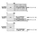
図6は、電力需要家A、B、Cそれぞれの契約条件を示す図である。なお、契約条件の情報は、設定情報に含まれる。電力需要家Aは、電力需要家Aのビルにおける平時の負荷の電力消費量の100%、上限500kWを、ギャランティー型の供給要求電力として契約している。ギャランティー型は、電力供給が保障されることを示す。
An example of power supply to power consumers in an emergency in thepower control system 15 will be described with reference to FIGS.
FIG. 6 is a diagram showing the contract conditions of the power consumers A, B, and C. The contract condition information is included in the setting information. The powerconsumer A contracts 100% of the power consumption of the load in the normal time in the building of the power consumer A and the upper limit of 500 kW as the guarantee type power supply demand. The guarantee type indicates that power supply is guaranteed.

電力需要家Bは、電力需要家Bのビルにおける平時の負荷の電力消費量の30%、上限150kWをギャランティー型の供給要求電力として、同じく平時の負荷の電力消費量の30%、上限150kWをさらにベストエフォート型の供給要求電力として契約している。ベストエフォート型は、予備電源に供給可能な余剰の電力がある場合に供給される電力量の上限を示す。  The power customer B uses 30% of the power consumption of the normal load in the building of the power consumer B and the upper limit of 150 kW as the guarantee-type power supply requirement, and similarly 30% of the power consumption of the normal load and the upper limit of 150 kW. Is contracted as the best-effort power supply requirement. The best effort type indicates the upper limit of the amount of power supplied when there is surplus power that can be supplied to the standby power supply.

電力需要家Cは、電力需要家Cのビルにおける平時の負荷の電力消費量の30%、上限150kWをベストエフォート型の供給要求電力として契約している。  The power consumer C contracts 30% of the power consumption of the load during normal times in the building of the power consumer C and the upper limit of 150 kW as the best effort type power supply requirement.

電力需要家A、B、Cの電力供給の優先度はそれぞれ、高、中、低である。また、電力需要家Aのギャランティー型、電力需要家Bのギャランティー型、電力需要家Bのベストエフォート型、電力需要家Cのベストエフォート型の順に電力供給の優先度が高い。  The priority of power supply of the power consumers A, B, and C is high, medium, and low, respectively. Moreover, the priority of power supply is high in order of the guarantee type of the electric power consumer A, the guarantee type of the electric power consumer B, the best effort type of the electric power consumer B, and the best effort type of the electric power consumer C.

図7は、電力制御システム15の電力需要ピーク時期における非常時の電力需要家への電力供給例を示す図である。制御装置45の需要量算出部454は、予測対象時間の時間帯、季節、曜日等と同じ又は類似した条件における過去負荷トレンドや、過去、現在及び予測の天候、気象条件等の外部要因等の少なくとも一部の情報に基づいて、予測対象時間内の各時刻において停電が発生、継続した場合に、電力需要家A〜Cにどれだけの電力供給が必要になるかの電力需要量をリアルタイムに算出する。ここでは、需要量算出部454は、電力需要家Aの電力需要量がギャランティー型500kW、電力需要家Bの電力需要量がギャランティー型150kW、ベストエフォート型150kW、電力需要家Cの電力需要量がギャランティー型150kWであると算出する。  FIG. 7 is a diagram illustrating an example of power supply to power consumers in an emergency in the power demand peak period of thepower control system 15. The demand amount calculation unit 454 of thecontrol device 45 includes a past load trend under the same or similar conditions as the time zone, season, day of the week, etc., external factors such as past, present and forecast weather, weather conditions, etc. Based on at least some of the information, if a power outage occurs and continues at each time within the prediction target time, the amount of power demand for how much power is required for the power consumers A to C is calculated in real time. calculate. Here, the demand amount calculation unit 454 has a power demand amount of the power customer A of 500 kW for the guarantee type, a power demand amount of the power consumer B of 150 kW for the guarantee type, a best effort type of 150 kW, and a power demand of the power consumer C. The amount is calculated to be a guarantee type 150 kW.

さらに、制御装置45の供給量算出部455は、各電力需要家A〜Cへ非常時に電力を供給する候補の電力供給元である電力供給元候補の供給元電力システム25のそれぞれについて供給可能電力量を算出する。供給量算出部455は、各電力需要家A〜Cの電力需要量、電力供給元候補の供給可能電力量の多寡、供給元電力システム25から需要家電力システム35までの送電距離等による損失が最小となる組み合わせ等から、各電力需要家A〜Cへ電力を供給する電力供給元を判断する。  Furthermore, the supply amount calculation unit 455 of thecontrol device 45 can supply power for each of the power source candidate powersource power systems 25 that are power source candidates that supply power to the power consumers A to C in an emergency. Calculate the amount. The supply amount calculation unit 455 has a loss due to the power demand amount of each of the power consumers A to C, the amount of suppliable power amount of the power supply source candidates, the transmission distance from the supplysource power system 25 to theconsumer power system 35, and the like. The power supply source that supplies power to each of the power consumers A to C is determined from the combination that is minimized.

なお、供給量算出部455は、経済的合理性に基づいて、各電力需要家への供給優先順位を判断してもよい。例えば、電力供給元A〜Cから供給可能な電力量が、全ての電力需要家A〜Cが必要とする電力量に対して不足する場合、供給量算出部455は、電力需要家への電力供給による収入金額が最も高くなる組み合わせによって、各電力需要家へ電力を供給する電力供給元を決定する。あるいは、供給量算出部455は、電力供給元A〜Cから供給可能な電力量が、電力需要家A〜Cのギャランティー型による電力供給に必要な電力量の合計に対して不足する場合には、ギャランティー型の電力量が賄えなかったときのペナルティー金額が最小となる組み合わせによって、各電力需要家へ電力を供給する電力供給元を決定する。ペナルティー金額は、例えば、電力需要家との間のサービスレベルアグリーメント(SLA)によって予め決められる。  The supply amount calculation unit 455 may determine the priority order of supply to each power consumer based on economic rationality. For example, when the amount of power that can be supplied from the power supply sources A to C is insufficient with respect to the amount of power required by all the power consumers A to C, the supply amount calculation unit 455 supplies the power to the power consumers. An electric power supply source that supplies electric power to each electric power consumer is determined according to a combination in which the amount of income from supply becomes the highest. Or supply amount calculation part 455, when the amount of electric power which can be supplied from electric power supply sources AC is insufficient with respect to the total amount of electric power required for the power supply by the guarantee type of electric power consumers AC. Determines a power supply source that supplies power to each power consumer by a combination that minimizes the penalty amount when the guarantee type power amount cannot be covered. The penalty amount is determined in advance by, for example, a service level agreement (SLA) with a power consumer.

例えば、供給量算出部455は、電力供給元Aからの供給可能電力量が600kW、電力供給元Bからの供給可能電力量が200kW、電力供給元Cからの供給可能電力量が100kWであると算出する。電力供給元間での電力融通がない場合、供給量算出部455は、ギャランティー型を優先させ、電力供給元Aから電力需要家Aへ500kW、電力供給元Bから電力需要家Bへ150kWを供給すると判断する。電力供給元Cから電力供給が可能な電力量は、電力需要家B、Cのベストエフォート型での供給が必要な電力用に満たないため、電力供給は行わない。電力供給元間での電力融通がある場合、供給量算出部455は、電力供給元B、Cは、他の電力供給元の供給元電力システム25から電力の融通が可能である場合、その電力を受けて電力需要家B、Cのベストエフォート型の電力需要量の電力供給を行う。  For example, the supply amount calculation unit 455 determines that the suppliable power amount from the power supply source A is 600 kW, the suppliable power amount from the power supply source B is 200 kW, and the suppliable power amount from the power supply source C is 100 kW. calculate. When there is no power interchange between the power supply sources, the supply amount calculation unit 455 gives priority to the guarantee type and gives 500 kW from the power supply source A to the power consumer A, and 150 kW from the power supply source B to the power consumer B. Judge to supply. Since the amount of power that can be supplied from the power supply source C is less than the amount of power that needs to be supplied by the power consumers B and C in the best effort type, the power supply is not performed. When there is power accommodation between the power supply sources, the supply amount calculation unit 455 determines that the power supply sources B and C have the power when the power supply from thesupply power system 25 of the other power supply source is possible. In response, the power consumers B and C supply power of the best effort type power demand.

図8は、電力制御システム15の電力需要オフピーク時期における非常時の電力需要家への電力供給例を示す図である。制御装置45の需要量算出部454は、上記と同様に、各時刻において停電が発生、継続した場合に電力需要家A〜Cにどれだけの電力供給が必要になるかの電力需要量をリアルタイムに算出する。需要量算出部454は、電力需要家Aの電力需要量がギャランティー型250kW、電力需要家Bの電力需要量がギャランティー型75kW、ベストエフォート型75kW、電力需要家Cの電力需要量がギャランティー型75kWであると算出する。  FIG. 8 is a diagram illustrating an example of power supply to power consumers in an emergency in the power demand off-peak period of thepower control system 15. Similarly to the above, the demand amount calculation unit 454 of thecontrol device 45 provides real-time power demand amount indicating how much power supply is required to the power consumers A to C when a power failure occurs and continues at each time. To calculate. The demand amount calculation unit 454 has a power demand amount of 250 kW for the power consumer A, a power demand amount of 75 kW for the power consumer B, a 75 kW best effort type, and a power demand amount for the power consumer C. It is calculated that the tee type is 75 kW.

さらに、制御装置45の供給量算出部455は、上記と同様に、各電力需要家A〜Cへ非常時に電力を供給する電力供給元候補の供給元電力システム25のそれぞれについて供給可能電力量を算出する。例えば、供給量算出部455は、電力供給元Aからの供給可能電力量が600kW、電力供給元Bからの供給可能電力量が200kW、電力供給元Cからの供給可能電力量が100kWであると算出する。供給量算出部455は、ギャランティー型を優先させ、電力供給元Aから電力需要家Aへ250kW、電力供給元Bから電力需要家Bへ75kWを供給すると判断する。続いて、供給量算出部455は、電力供給元Bに余剰電力があるため、電力供給元Bから電力需要家Bへベストエフォート型の75kWを供給し、電力供給元Cからは電力需要家Cへ75kWを供給すると判断する。  Further, similarly to the above, the supply amount calculation unit 455 of thecontrol device 45 calculates the suppliable power amount for each of the power source candidatepower source systems 25 that supply power to the power consumers A to C in an emergency. calculate. For example, the supply amount calculation unit 455 determines that the suppliable power amount from the power supply source A is 600 kW, the suppliable power amount from the power supply source B is 200 kW, and the suppliable power amount from the power supply source C is 100 kW. calculate. The supply amount calculation unit 455 gives priority to the guarantee type, and determines that 250 kW is supplied from the power supply source A to the power consumer A and 75 kW is supplied from the power supply source B to the power consumer B. Subsequently, since the power supply source B has surplus power, the supply amount calculation unit 455 supplies best effort type 75 kW from the power supply source B to the power consumer B, and the power supplier C It is determined that 75 kW will be supplied.

上記のように、制御装置45は、電力需要家の電力需要量を判断し、ギャランティー型の電力需要量を供給しても余剰電力があるときには、その剰余電力をベストエフォート型で契約している電力需要家など、優先度が低い電力需要家へ供給することができる。例えば、オフピークの期間のほか、夜間などは電力消費量が昼間よりも低いことがある。そこで、ギャランティー型で契約している供給電力要求量よりも実際の電力消費量が低いことが予想される場合は、その余剰分を優先度が低い電力需要家へ供給することができる。従って、従来のように実際の電力消費量が低いことが予想される場合でもギャランティー型の供給電力要求量を常に確保しておく場合と比較し、多くの電力需要家に電力を供給できる可能性がある。  As described above, thecontrol device 45 determines the power demand amount of the power consumer, and if there is surplus power even if the guarantee type power demand amount is supplied, the surplus power is contracted on a best effort basis. It can be supplied to low-priority power consumers such as existing power consumers. For example, the power consumption may be lower than during the daytime in addition to the off-peak period. Therefore, when it is expected that the actual power consumption is lower than the supply power requirement amount contracted with the guarantee type, the surplus can be supplied to the power consumers with low priority. Therefore, even when actual power consumption is expected to be low as in the past, it is possible to supply power to a large number of power consumers as compared with the case where a guarantee type supply power requirement is always secured. There is sex.

また、ギャランティー型、ベストエフォート型の供給電力要求量を、常時の電力消費量に対する割合として設定することができる。このような設定にすることで、オフピーク期間や夜間など電力消費量が低いことが予想される場合には、より効率的に、多くの電力需要家へ電力を供給することが可能となる。  Also, the guarantee-type and best-effort supply power requirements can be set as a ratio to the normal power consumption. With this setting, when the power consumption is expected to be low, such as during off-peak periods or at night, it is possible to supply power to many power consumers more efficiently.

図9は、電力制御システム15における非常時の電源供給処理を示すフロー図である。非常時の電源供給処理において、制御装置45は、各電力需要家について予想される停電発生時の電力需要量をリアルタイムに管理し、どの電力供給元のビルの供給元電力システム25から、どの電力需要家のビルの需要家電力システム35に電力を供給するかを判断する。制御装置45は、電力供給先となる電力需要家の優先度付けを実施し、供給元電力システム25に電力供給を指示する。供給元電力システム25の給電制御装置251は、制御装置45からの指示に従って、自システムが備える非常用発電装置254や蓄電装置256から需要家電力システム35に電力を供給するための制御を行う。以下に非常時の電源供給処理を詳細に説明する。  FIG. 9 is a flowchart showing power supply processing in an emergency in thepower control system 15. In an emergency power supply process, thecontrol device 45 manages the power demand in the event of a power failure that is predicted for each power consumer in real time, and selects which power from thepower supply system 25 of which power supply source building. It is determined whether to supply power to theconsumer power system 35 of the customer's building. Thecontrol device 45 prioritizes power consumers as power supply destinations and instructs thepower supply system 25 to supply power. In accordance with an instruction from thecontrol device 45, the powersupply control device 251 of the supplysource power system 25 performs control for supplying power from the emergency power generation device 254 and thepower storage device 256 included in the own system to theconsumer power system 35. The emergency power supply process will be described in detail below.

制御装置45の需要量算出部454は、各時刻において停電が発生、継続した場合に各電力需要家にどれだけの電力供給が必要になるかの予想の電力需要量をリアルタイムに、例えば、数分から数十分などの時間間隔で算出する(ステップS105)。需要量算出部454は、電力需要量の予測を、例えば、予測対象時間の季節、時間帯、曜日等が同じ又は類似した条件における負荷装置353の負荷変動のトレンド、天候、気象条件等の外部要因などに基づいて行う。  The demand amount calculation unit 454 of thecontrol device 45 calculates the expected power demand amount in real time, for example, the number of power supply required for each power consumer when a power failure occurs and continues at each time Calculation is performed at time intervals such as minutes to several tens of minutes (step S105). The demand amount calculation unit 454 predicts the power demand amount, for example, the trend of the load fluctuation of theload device 353 under the same or similar conditions of the forecast target time, such as season, time zone, day of the week, weather, weather conditions, etc. Based on factors.

各需要家電力システム35の受変電装置351は、電力系統の停電発生を監視する。受変電装置351は、交流系統網511により供給される商用電力の停電発生を検出した場合、停電信号を制御装置45に送信する(ステップS110)。制御装置45の情報収集部451は、停電信号を受信し、受信した停電信号に設定されている送信元の情報から、停電が発生した需要家電力システム35を判断する(ステップS115)。  The power receiving / transformingdevice 351 of eachconsumer power system 35 monitors the occurrence of a power failure in the power system. The power receiving / transformingdevice 351 transmits a power failure signal to thecontrol device 45 when detecting the occurrence of a power failure of the commercial power supplied from the AC grid 511 (step S110). Theinformation collecting unit 451 of thecontrol device 45 receives the power failure signal, and determines theconsumer power system 35 in which the power failure has occurred from the information of the transmission source set in the received power failure signal (step S115).

需要量算出部454は、情報記憶部452に記憶される設定情報から読み出した各電力需要家の優先度に基づいて、停電が発生した各電力需要家への電力供給の優先度を算出する(ステップS120)。なお、設定情報は、電力需要家との契約等に基づいて予め設定される。  The demand amount calculation unit 454 calculates the priority of power supply to each power consumer in which a power failure has occurred based on the priority of each power consumer read from the setting information stored in the information storage unit 452 ( Step S120). The setting information is set in advance based on a contract with a power consumer.

供給量算出部455は、停電が発生した電力需要家に対する電力供給元候補を選択する。電力供給元候補は全ての供給元電力システム25としてもよく、需要家電力システム35から所定距離以内の需要家電力システム35などとしてもよく、需要家電力システム35それぞれの電力供給元候補となり得る供給元電力システム25の情報を設定情報に含めて設定しておいてもよい。供給量算出部455は、選択した電力供給元候補の供給元電力システム25それぞれについて供給可能電力量を算出する(ステップS125)。  The supply amount calculation unit 455 selects a power supply source candidate for a power consumer in which a power failure has occurred. The power supply source candidates may be all the powersource power systems 25, may be thecustomer power system 35 within a predetermined distance from thecustomer power system 35, and the supply that can be a power source candidate for each of theconsumer power systems 35. Information of theoriginal power system 25 may be set in the setting information. The supply amount calculation unit 455 calculates the suppliable power amount for each of the selected power supply source candidate supply source power systems 25 (step S125).

指示部456は、停電が発生した各電力需要家の予測される電力需要量及び優先度、電力供給元候補の供給元電力システム25からの供給可能電力量の多寡、送電距離等による損失が最小となる組み合わせ等に基づいて、いずれの供給元電力システム25から、停電が発生したいずれの需要家電力システム35へどれだけの電力を供給するかを判断する。具体的には、優先度や、電力供給元と電力供給先の電力需要家との組み合わせなどを決めるパラメーターは、以下のうち1以上である。  Theinstruction unit 456 minimizes the loss due to the predicted power demand and priority of each power consumer in which a power failure has occurred, the amount of power that can be supplied from thepower source system 25 of the power source candidate, the transmission distance, etc. Based on the combination and the like, it is determined how much power is supplied from which supplypower system 25 to whichconsumer power system 35 in which a power failure has occurred. Specifically, the parameter that determines the priority and the combination of the power supply source and the power consumer of the power supply destination is one or more of the following.

(1)電力供給元及び電力供給先の供給優先度。
(2)リアルタイムに算出した各電力供給元の供給元電力システム25における供給可能電力量。
(3)各電力需要家の非常時の供給要求電力。各電力需要家おいて停電が発生した場合に必要な負荷容量の予測値であり、ギャランティー型として供給が必要な電力量と、ベストエフォートの電力量との合計である。
(4)各電力需要家において供給が必要な時間(停電後2時間等の供給継続時間)。
(5)供給元電力システム25と需要家電力システム35間の送電距離等による給電損失。
(6)供給ルート(交流系統網511を通じて給電か、自営線網512を通じて給電か、自営線521を通じて給電か。)。
(7)被災状況に応じた電力供給ルートの判断結果。
(1) Supply priority of the power supply source and the power supply destination.
(2) The amount of power that can be supplied in the powersource power system 25 of each power source calculated in real time.
(3) Supply demand power in an emergency of each power consumer. This is a predicted value of the load capacity required when a power outage occurs in each power consumer, and is the total of the amount of power that needs to be supplied as a guarantee type and the amount of power at best effort.
(4) Time required for supply at each electric power consumer (supply continuation time such as 2 hours after a power failure).
(5) Power supply loss due to the transmission distance between thesupplier power system 25 and theconsumer power system 35 or the like.
(6) Supply route (whether power is supplied through theAC network 511, power is supplied through theprivate network 512, or power is supplied through the private line 521).
(7) The determination result of the power supply route according to the disaster situation.

指示部456は、判断結果に基づいて、優先順位に従い、停電が発生した電力供給先の需要家電力システム35へ電力供給を開始するよう供給元電力システム25に指示し、電力供給先の需要家電力システム35に供給元電力システム25からの供給電力の受電を開始するよう指示する(ステップS130)。供給元電力システム25への指示には、非常用発電装置254の発電量や、蓄電装置256からの放電量などの指示も含まれ得る。  Based on the determination result, theinstruction unit 456 instructs the supplysource power system 25 to start power supply to theconsumer power system 35 of the power supply destination where the power failure has occurred according to the priority order, and the consumer electronics of the power supply destination Thepower system 35 is instructed to start receiving the power supplied from the supply source power system 25 (step S130). The instructions to the supplysource power system 25 may include instructions such as the amount of power generated by the emergency power generation device 254 and the amount of discharge from thepower storage device 256.

また、供給元電力システム25の蓄電装置256の放電可能電力量が、供給元電力システム25における電力需要量と、電力供給先の需要家電力システム35における電力需要量との合計に満たない場合は、指示部456は、負荷装置257及び負荷装置353の一部への電力供給を停止すると判断する。指示部457は、電力供給を停止する負荷装置257及び負荷装置353を、情報記憶部452に記憶される設定情報から読み出した停止可能負荷タイムテーブル、あるいは、負荷装置257や負荷装置353の優先度等に基づいて決定する。指示部456は、負荷装置257の一部の電力供給の停止を供給元電力システム25の給電制御装置251に指示する。また、指示部456は、負荷装置353の一部の電力供給の停止するよう需要家電力システム35の変換装置352を制御する。  Further, when the dischargeable power amount of thepower storage device 256 of the supplysource power system 25 is less than the total of the power demand amount in the supplysource power system 25 and the power demand amount in theconsumer power system 35 of the power supply destination Theinstruction unit 456 determines to stop power supply to theload device 257 and a part of theload device 353. The instruction unit 457 reads theload device 257 and theload device 353 that stop power supply from the setting information stored in theinformation storage unit 452, or the priority of theload device 257 and theload device 353. Etc. are determined. Theinstruction unit 456 instructs the powersupply control device 251 of the supplysource power system 25 to stop the partial power supply of theload device 257. In addition, theinstruction unit 456 controls theconversion device 352 of theconsumer power system 35 so as to stop a part of the power supply of theload device 353.

制御装置45からの指示に従って、供給元電力システム25は予備電源からの電力を需要家電力システム35に供給し、需要家電力システム35は、供給元電力システム25から供給される電力を受電し、負荷装置353に供給する(ステップS135)。具体的には、供給元電力システム25の給電制御装置251は、制御装置45からの指示に従って、非常用発電装置254が発電した電力や、蓄電装置256から放電された電力を、交流系統網511と自営線521の一方又は両方、もしくは、自営線網512と自営線521の一方又は両方により、需要家電力システム35に供給するよう制御する。また、給電制御装置251は、制御装置45からの指示に従って、負荷装置257の一部への電力供給を停止する。需要家電力システム35は、供給元電力システム25から供給される交流電力を受電する場合、その交流電力を、交流系統網511を介して受変電装置351により受電するか、受変電装置351を自営線網512に切替えて受電する。需要家電力システム35は、供給元電力システム25から供給される直流電力を受電する場合、その直流電力を、自営線521を介して変換装置352により受電する。需要家電力システム35は、供給元電力システム25から受電した電力を負荷装置353に供給する。  In accordance with an instruction from thecontrol device 45, the supplysource power system 25 supplies power from the standby power source to theconsumer power system 35, and theconsumer power system 35 receives the power supplied from the supplysource power system 25, It supplies to the load apparatus 353 (step S135). Specifically, the powersupply control device 251 of the supplysource power system 25 converts the power generated by the emergency power generation device 254 and the power discharged from thepower storage device 256 into theAC grid 511 in accordance with an instruction from thecontrol device 45. And one or both of theprivate line 521, or one or both of theprivate line network 512 and theprivate line 521, theconsumer power system 35 is controlled to be supplied. In addition, the powersupply control device 251 stops power supply to a part of theload device 257 in accordance with an instruction from thecontrol device 45. When thecustomer power system 35 receives AC power supplied from thesupplier power system 25, thecustomer power system 35 receives the AC power by the power receiving / transformingdevice 351 via theAC network 511, or operates the power receiving / transformingdevice 351 independently. Switch to thewire network 512 to receive power. When theconsumer power system 35 receives the DC power supplied from thesupplier power system 25, theconsumer power system 35 receives the DC power by theconversion device 352 via theprivate line 521. Thecustomer power system 35 supplies the power received from the supplysource power system 25 to theload device 353.

需要家電力システム35の受変電装置351は、電力系統の復電信号を監視する。受変電装置351は、商用電力の復電を確認すると、復電通知信号を制御装置45に送信する(ステップS140)。制御装置45の情報収集部451が復電信号を受信すると(ステップS145)、指示部456は、全ての電力需要家の需要家電力システム35が復電したかを判断する(ステップS150)。指示部456は、まだ復電していない需要家電力システム35があると判断した場合、ステップS130(あるいは、ステップS120又はステップS125)からの処理を行い、優先度順位に従って、いずれの供給元電力システム25から、復電した需要家電力システム35を除く未だ停電中の需要家電力システム35へ電力を供給するかを指示する。例えば、指示部456は、停電信号の受信からの経過時間が所定時間以内の場合はステップS130からの処理を、所定時間を超えた場合はステップS120又はステップS125からの処理を行うようにしてもよい。  The power receiving / transformingdevice 351 of theconsumer power system 35 monitors a power recovery signal of the power system. When the power receiving / transformingdevice 351 confirms that the commercial power is restored, the power receiving / transformingdevice 351 transmits a power restoration notification signal to the control device 45 (step S140). When theinformation collection unit 451 of thecontrol device 45 receives the power recovery signal (step S145), theinstruction unit 456 determines whether theconsumer power systems 35 of all power consumers have recovered (step S150). When theinstruction unit 456 determines that there is aconsumer power system 35 that has not yet recovered power, theinstruction unit 456 performs the processing from step S130 (or step S120 or step S125), and according to the priority ranking, Thesystem 25 is instructed whether to supply power to thecustomer power system 35 that is still in a power outage, excluding the restoredcustomer power system 35. For example, theinstruction unit 456 may perform the process from step S130 when the elapsed time from the reception of the power failure signal is within a predetermined time, and perform the process from step S120 or step S125 when the predetermined time is exceeded. Good.

そして、指示部456は、全ての電力需要家の需要家電力システム35が復電したと判断した場合、供給元電力システム25に、非常用発電装置254、蓄電装置256等の予備電源からの電力供給を停止するよう指示し、需要家電力システム35に商用電力の受電を指示する(ステップS155)。供給元電力システム25の給電制御装置251は、制御装置45からの指示に従い、非常用発電装置254の発電、蓄電装置256の放電、変換装置253から自営線521への送電を停止し、受変電装置252が交流系統網511から商用電力を受電するよう制御する。需要家電力システム35の受変電装置351は、自営線網512からの受電を行っていた場合には交流系統網511からの受電に切替え、自営線521からの受電を停止する(ステップS160)。電力制御システム15は、図9の処理を繰り返す。  And when the instruction |indication part 456 judges that the consumerelectric power system 35 of all the electric power consumers was restored, the electric power from standby power supplies, such as the emergency power generator 254 and theelectrical storage apparatus 256, is supplied to the supply sourceelectric power system 25. The supply is instructed to be stopped, and theconsumer power system 35 is instructed to receive commercial power (step S155). In accordance with an instruction from thecontrol device 45, the powersupply control device 251 of the supplysource power system 25 stops the power generation of the emergency power generation device 254, the discharge of thepower storage device 256, and the power transmission from theconversion device 253 to theprivate line 521. Thedevice 252 is controlled to receive commercial power from theAC grid 511. The power receiving / transformingdevice 351 of theconsumer power system 35 switches to receiving power from theAC grid 511 when receiving power from theprivate network 512 and stops receiving power from the private line 521 (step S160). Thepower control system 15 repeats the process of FIG.

上述した実施形態によれば、例えば、広範囲で停電が起こった場合に、電力供給が可能な電力供給元から、医療機関を優先するなど、電力需要家の優先度に応じて電力を供給するとともに、各電力需要家において最低限必要な電力を優先して供給することができる。また、電力需要家における電力消費量が少なく、電力供給元に余剰の電力がある場合には、優先度の低い電力需要家にも電力を供給したり、ベストエフォート型などの優先度が低い供給要求電力量の電力についても電力需要家へ供給したりすることが可能となる。  According to the above-described embodiment, for example, when a power failure occurs in a wide range, power is supplied from a power supply source that can supply power according to the priority of power consumers, such as giving priority to medical institutions. , It is possible to preferentially supply the minimum necessary power in each power consumer. In addition, when there is little power consumption by power consumers and there is surplus power at the power supply source, power is also supplied to low-priority power consumers or low-priority supply such as best effort type It is also possible to supply power demand to the power consumer.

[第5の実施形態]
本実施形態の電力制御システムは、蓄電池を商用電源の停電が発生していない常時用として使用し、顧客の電力システムにおける自家発電量・電力消費量・電力料金(時間別)等からコスト最適となる充放電方法を算出し蓄電池充放電を制御する。
[Fifth Embodiment]
The power control system of the present embodiment uses the storage battery as a constant power source that does not cause a power failure of the commercial power source, and is optimal in cost from the amount of private power generation, power consumption, power charge (by hour), etc. in the customer's power system The charge / discharge method is calculated to control storage battery charge / discharge.

図10は、本実施形態の電力制御システムの動作概要を示す図である。ビルには、蓄電池を有する供給元電力システムが備えられる。供給元電力システムは、常時・非常時に発電を行う発電機や、非常時に発電を行う非常用発電機をさらに備え得る。同図においては、ビルを1つみ示しているが、供給元電力システムが設置されたビルの数は任意とすることができる。供給元電力システムは、常時に蓄電池の放電又は蓄電を行い、放電した電力については、ビル内の負荷に供給したり、小売電気事業者等に売電したり、調整力取引市場等に売電したりする。あるいは、供給元電力システムは、蓄電池が放電した電力を、電力需要家のビルに供給(又は売電)してもよい。  FIG. 10 is a diagram showing an outline of the operation of the power control system of the present embodiment. The building is equipped with a supplier power system having a storage battery. The supplier power system may further include a generator that generates power at all times and in an emergency, and an emergency generator that generates power in an emergency. Although only one building is shown in the figure, the number of buildings in which the power supply system is installed can be arbitrarily set. The supplier's power system always discharges or stores the storage battery, and supplies the discharged power to a load in the building, sells it to a retail electricity supplier, etc. To do. Alternatively, the supplier power system may supply (or sell) the power discharged from the storage battery to the building of the power consumer.

電力制御システムは、ビルに設置された発電機の発電量、各負荷の電力消費量などの状態情報をリアルタイムに収集し、過去に収集したこれらの状態情報を状態情報として記憶している。さらに、電力制御システムは、外部から収集した天候(気温、湿度)や、調整力取引市場等における市場取引価格をリアルタイムに収集し、外部収集情報として記憶している。電力制御システムは、過去、現在及び予測の状態情報と、電気料金タリフの情報と、過去、現在及び予測の天候の情報や市場取引価格等の売電価格の情報と、予測対象時間の時間帯、曜日、季節等の情報とのうち少なくとも一部の情報を用いた任意の予測技術により、予測対象時間において最もコスト最適となる蓄電池充放電のタイミングを決定する。電気料金タリフは、時間帯別の単位電力消費量当たりの商用電力の料金を示す。この電気料金タリフは、ダイナミックプライシング等のリアルタイムに変動する価格形態を含んでもよい。また、売電価格は、例えば市場価格(スポット価格、先物等)、インバランス料金価格、相対契約価格、FIT(Feed-in Tariff)価格などが考えられる。例えば、夜間は電気料金が低いため、夜間に蓄電池へ蓄電し、昼間に放電するようにすることで、電気料金の値差を利用してコストを削減できる。また、予測対象時間の時間帯、天候、季節、市場取引価格等の条件が、市場取引価格が高いときの条件と類似している場合に、売電することでもコストを削減できる可能性がある。電力制御システムは、決定した蓄電池充放電のタイミングに基づいて、コストを最適化するように蓄電池の充放電をリアルタイムで制御する。  The power control system collects status information such as the amount of power generated by a generator installed in a building and the power consumption of each load in real time, and stores the status information collected in the past as status information. Furthermore, the power control system collects the weather (temperature, humidity) collected from the outside and the market transaction price in the adjustment power transaction market in real time and stores it as external collection information. The power control system consists of past, present and forecast status information, electricity tariff information, past, present and forecast weather information, information on power selling prices such as market transaction prices, and forecast time periods. The storage battery charging / discharging timing at which the cost is optimal in the prediction target time is determined by an arbitrary prediction technique using at least a part of the information such as day of the week and season. Electricity tariff indicates the price of commercial power per unit power consumption by time zone. This electricity tariff may include a price form that varies in real time, such as dynamic pricing. The power selling price may be, for example, market price (spot price, futures, etc.), imbalance fee price, relative contract price, FIT (Feed-in Tariff) price, and the like. For example, since the electricity charge is low at night, it is possible to reduce the cost by using the value difference of the electricity charge by storing electricity in the storage battery at night and discharging it during the day. In addition, if the conditions such as the forecast time zone, weather, season, market transaction price, etc. are similar to the conditions when the market transaction price is high, it may be possible to reduce costs by selling power. . The power control system controls charge / discharge of the storage battery in real time so as to optimize the cost based on the determined storage battery charge / discharge timing.

図11は、第5の実施形態による電力制御システム16の構成を示す機能ブロック図であり、本実施形態と関係する機能ブロックのみを抽出して示してある。同図において、図5に示す第4の実施形態による電力制御システム15と同一の部分には同一の符号を付し、その説明を省略する。電力制御システム16は、1以上の供給元電力システム25と、1以上の需要家電力システム35と、供給元電力システム25及び需要家電力システム35を制御する制御装置46とを有する。なお、電力供給元が需要家電力システム35への電力供給を行わない場合、電力制御システム16は需要家電力システム35を備えなくてもよい。この場合、供給元電力システム25の受変電装置252は、自営線網512と接続されず、変換装置253は、自営線521と接続されない。  FIG. 11 is a functional block diagram showing the configuration of thepower control system 16 according to the fifth embodiment, and only functional blocks related to the present embodiment are extracted and shown. In this figure, the same parts as those of thepower control system 15 according to the fourth embodiment shown in FIG. Thepower control system 16 includes one or more supplysource power systems 25, one or moreconsumer power systems 35, and acontrol device 46 that controls the supplysource power system 25 and theconsumer power system 35. When the power supply source does not supply power to theconsumer power system 35, thepower control system 16 may not include theconsumer power system 35. In this case, the power receiving / transformingdevice 252 of the supplysource power system 25 is not connected to theprivate line network 512, and theconversion device 253 is not connected to theprivate line 521.

制御装置46は、情報収集部461、情報記憶部462及び制御部463を備える。情報記憶部462は、第1〜第3の実施形態の情報記憶部402、412、422に相当し、情報収集部461は、第1〜第3の実施形態の情報収集部401、411、421に相当する。制御部463は、第1〜第3の実施形態の制御部403、413、423に相当する。  Thecontrol device 46 includes aninformation collection unit 461, aninformation storage unit 462, and acontrol unit 463. Theinformation storage unit 462 corresponds to theinformation storage units 402, 412, and 422 of the first to third embodiments, and theinformation collection unit 461 is theinformation collection units 401, 411, and 421 of the first to third embodiments. It corresponds to. Thecontrol unit 463 corresponds to thecontrol units 403, 413, and 423 of the first to third embodiments.

情報収集部461は、供給元電力システム25から状態情報を収集し、外部の装置から天候(気温、湿度)の情報や、調整力取引市場等におけるリアルタイムの市場取引価格等の情報を取得する。情報記憶部462は、各種情報を記憶する。情報記憶部462は、情報収集部461が収集した状態情報を、情報の収集時刻と対応付けた実績情報を記憶する。また、情報記憶部462は、天候、市場取引価格等の情報を、情報の収集時刻と対応付けて外部収集情報として記憶する。さらに、情報記憶部462は、電力供給元の各負荷の優先度及び定格電力消費量、停止可能負荷タイムテーブルなどの設定情報や、商用電力の電気料金タリフなどを含む各種情報を記憶する。  Theinformation collecting unit 461 collects state information from the supplysource power system 25, and acquires information such as weather (temperature, humidity) and real-time market transaction price in an adjustment power transaction market from an external device. Theinformation storage unit 462 stores various types of information. Theinformation storage unit 462 stores performance information in which the state information collected by theinformation collection unit 461 is associated with the information collection time. Further, theinformation storage unit 462 stores information such as weather and market transaction prices as external collection information in association with information collection time. Further, theinformation storage unit 462 stores various information including setting information such as priority and rated power consumption of each load of the power supply source, stoptable load time table, and electricity tariff for commercial power.

制御部463は、情報記憶部462に記憶される電力タリフと、情報収集部461が取得した又は情報記憶部462に記憶される過去、現在及び予測の状態情報、調整力取引市場等における過去、現在及び予測の市場取引価格、過去、現在及び予測の天候などの情報と、予測対象時間の時間帯、曜日、季節等の情報とのうち少なくとも一部の情報に基づいて、任意の予測技術により、予測対象時間(例えば、現在から所定時間先までの間)において料金を低減できる蓄電装置256の常時における充放電スケジュールを所定の時間ごとに算出する。放電を行う場合、制御部463は、放電された電力を売電するか、負荷装置257へ供給するか、需要家電力システム35に供給するかを決定する。制御部463は、充放電スケジュールに従って、供給元電力システム25の給電制御装置251に蓄電装置256の充放電を指示する。需要家電力システム35への供給を行う場合、制御部463は、需要家電力システム35に供給元電力システム25からの受電を指示する。  Thecontrol unit 463 includes the power tariff stored in theinformation storage unit 462, the past acquired by theinformation collection unit 461 or stored in theinformation storage unit 462, the current and predicted state information, the past in the adjustment power trading market, Based on at least a part of information such as current and forecast market transaction price, past, present and forecast weather and forecast time, day of the week, season, etc., by any forecast technology The charging / discharging schedule of thepower storage device 256 that can reduce the charge during the prediction target time (for example, from the present to a predetermined time ahead) is calculated for each predetermined time. When discharging, thecontrol unit 463 determines whether the discharged power is sold, supplied to theload device 257, or supplied to theconsumer power system 35. Thecontrol unit 463 instructs the powersupply control device 251 of the supplysource power system 25 to charge / discharge thepower storage device 256 according to the charge / discharge schedule. When supplying theconsumer power system 35, thecontrol unit 463 instructs theconsumer power system 35 to receive power from thesupplier power system 25.

供給元電力システム25の給電制御装置251は、制御装置46からの指示に従って、蓄電装置256からの充放電と、受変電装置252における交流系統網511又は自営線網512への送電あるいは交流系統網511からの受電、変換装置253における自営線521への送電又は送電停止を制御する。  In accordance with an instruction from thecontrol device 46, the powersupply control device 251 of the supplysource power system 25 performs charge / discharge from thepower storage device 256, power transmission to theAC grid network 511 or theprivate network 512 in the power receiving / transformingdevice 252, or an AC grid network. Power reception from 511, power transmission to theprivate line 521 in theconverter 253, or power transmission stop is controlled.

具体的には、常時に蓄電を行う場合、給電制御装置251は、受変電装置252が交流系統網511から受電するよう制御し、変換装置253が蓄電装置256への電力を供給し、自営線521への送電を停止するよう制御する。  Specifically, when power is always stored, the powerfeeding control device 251 controls the power receiving / transformingdevice 252 to receive power from theAC grid 511, theconversion device 253 supplies power to thepower storage device 256, and the private line Control is performed to stop power transmission to 521.

常時に蓄電装置256の放電を行い、負荷装置257へ供給する場合、給電制御装置251は、受変電装置252が交流系統網511との間の受電及び送電を停止するよう制御し、変換装置253が蓄電装置256から放電された電力を負荷装置257に供給するよう制御する。なお、蓄電装置256から放電される電力が負荷装置257の消費電力に満たない場合、給電制御装置251は、受変電装置252が交流系統網511から受電を行うよう制御する。  When thepower storage device 256 is always discharged and supplied to theload device 257, the powersupply control device 251 controls the power receiving / transformingdevice 252 to stop power reception and power transmission with theAC grid 511, and theconversion device 253. Controls to supply the electric power discharged from thepower storage device 256 to theload device 257. Note that when the power discharged from thepower storage device 256 is less than the power consumption of theload device 257, the powerfeeding control device 251 controls the power receiving / transformingdevice 252 to receive power from theAC grid 511.

また、常時に蓄電装置256の放電を行い、調整力取引市場等に売電する場合、給電制御装置251は、変換装置253が蓄電装置256から放電された電力を受変電装置252に送電し、受変電装置252が交流系統網511へ送電を行うよう制御する。  Further, when thepower storage device 256 is always discharged and sold to the adjustment power trading market or the like, the powerfeeding control device 251 transmits the power discharged from thepower storage device 256 to the power receiving / transformingdevice 252 by theconversion device 253, Control is performed so that the power receiving / transformingdevice 252 transmits power to theAC grid 511.

また、常時に蓄電装置256の放電を行い、需要家電力システム35に供給する場合、給電制御装置251は、変換装置253が蓄電装置256から放電された電力を受変電装置252に送電し、受変電装置252が交流系統網511又は自営線網512へ送電するよう制御するか、変換装置253が蓄電装置256から放電された電力を自営線521へ送電するよう制御する。あるいは、給電制御装置251は、変換装置253が蓄電装置256から放電された電力を受変電装置252及び自営線521に送電し、受変電装置252が交流系統網511又は自営線網512へ送電するよう制御してもよい。需要家電力システム35は、制御装置46からの指示に従い、受変電装置351における交流系統網51又は自営線網512からの受電と、変換装置352における自営線521からの受電との一方又は両方を行い、蓄電装置256から放電された電力を受電する。  When thepower storage device 256 is always discharged and supplied to theconsumer power system 35, the powersupply control device 251 transmits the power discharged from thepower storage device 256 to the power receiving / transformingdevice 252 by theconversion device 253. Thesubstation 252 is controlled to transmit power to theAC grid network 511 or theprivate network 512, or theconverter 253 is controlled to transmit power discharged from thepower storage device 256 to theprivate line 521. Alternatively, the powersupply control device 251 transmits the power discharged from thepower storage device 256 by theconversion device 253 to the power receiving / transformingdevice 252 and theprivate line 521, and the power receiving / transformingdevice 252 transmits the power to theAC grid network 511 or theprivate line network 512. You may control so. Theconsumer power system 35 receives one or both of power reception from theAC grid network 51 or theprivate network 512 in the power receiving / transformingdevice 351 and power reception from theprivate line 521 in theconversion device 352 in accordance with an instruction from thecontrol device 46. The power discharged from thepower storage device 256 is received.

例えば、晴天の日の場合、太陽光発電量が増加し、調整力が必要となり、調整力取引市場の市場価格が高騰する。制御装置46の制御部463は、調整力市場における売買による収益が商用電力の電気料金削減効果よりも大きいため、蓄電装置256に蓄電されている余裕分の電力を放電し、調整力取引市場に売却するよう制御を行う。電力システム26の給電制御装置251は、制御装置46からの指示に従って、蓄電装置256から放電し、受変電装置252から交流系統網511へ送電するよう制御する。  For example, on a sunny day, the amount of photovoltaic power generation increases, adjustment is required, and the market price of the adjustment trading market rises. Thecontrol unit 463 of thecontrol device 46 discharges the surplus power stored in thepower storage device 256 because the profit from buying and selling in the adjustment power market is larger than the electricity charge reduction effect of commercial power, and enters the adjustment power trading market. Control to sell. The powersupply control device 251 of the power system 26 controls to discharge from thepower storage device 256 and transmit power from the power receiving / transformingdevice 252 to theAC grid 511 in accordance with an instruction from thecontrol device 46.

一方で、雨天の日の場合、太陽光発電量がほとんどなく、調整力が不要となり、市場価格が下落する。制御装置46の制御部463は、調整力市場における売買による収益よりも、電気料金削減効果のほうが大きいため、昼間時間帯におけるピークシフトに蓄電装置256からの放電電力を活用すると判断する。供給元電力システム25の給電制御装置251は、制御装置46からの指示に従って、蓄電装置256から放電し、負荷装置257へ供給するよう制御する。  On the other hand, on a rainy day, there is almost no photovoltaic power generation, no adjustment is required, and the market price drops. Thecontrol unit 463 of thecontrol device 46 determines that the discharge power from thepower storage device 256 is used for the peak shift in the daytime time period because the effect of reducing the electricity bill is greater than the profit from trading in the adjustment power market. The powersupply control device 251 of the supplysource power system 25 controls to discharge from thepower storage device 256 and supply it to theload device 257 in accordance with an instruction from thecontrol device 46.

なお非常時に、制御装置46の制御部463は、情報記憶部462に記憶される実績情報と、情報収集部461が取得した又は情報記憶部462に記憶される過去、現在及び予測の状態情報及び天候などの情報と、予測対象時間の時間帯、曜日、季節等の情報とのうち少なくとも一部の情報に基づいて、任意の予測技術により、非常用発電装置254、発電装置255による発電量及び蓄電装置256からの放電量を算出する。制御部463は、算出結果に基づいて、供給元電力システム25に非常用発電装置254による発電、蓄電装置256からの放電、負荷装置257の一部停止等を指示する。供給元電力システム25の給電制御装置251は、制御装置46からの指示に従って、非常用発電装置254による発電及び蓄電装置256からの放電と、一部の負荷装置257の停止を行い、非常時に稼働させる負荷装置257のみに電力を供給するよう制御する。  In the event of an emergency, thecontrol unit 463 of thecontrol device 46 includes the actual information stored in theinformation storage unit 462, the past, current, and predicted state information acquired by theinformation collection unit 461 or stored in theinformation storage unit 462, and Based on at least part of the information such as the weather and the time zone, day of the week, season, etc. of the prediction target time, the power generation amount by the emergency power generation device 254 and the power generation device 255 and the The amount of discharge frompower storage device 256 is calculated. Based on the calculation result, thecontrol unit 463 instructs thesupply power system 25 to generate power by the emergency power generation device 254, discharge from thepower storage device 256, partial stop of theload device 257, and the like. The powersupply control device 251 of the supplysource power system 25 operates in an emergency by performing power generation by the emergency power generation device 254 and discharging from thepower storage device 256 and stopping some of theload devices 257 in accordance with instructions from thecontrol device 46. Control is performed so that power is supplied only to theload device 257 to be operated.

本実施形態によれば、常時において、省エネルギー、コスト削減のために顧客のビルに設置された蓄電池を活用することができる。また、供給元電力システムは、調整力取引市場等に売電する代わりに、蓄電池が放電した電力を所定の電力タリフにより電力需要家に売電してもよい。これにより、電力需要家は、商用電力よりも低い料金により電力を購入することも可能となる。また、電力供給元と電力需要家を、1対多又は多対多とすることで、1つの電力供給元の予備電源を複数の電力需要家で共有し、電力制御システム全体として予備電源の数を抑えることができる。  According to this embodiment, the storage battery installed in the customer's building can be utilized at all times for energy saving and cost reduction. Further, the supplier power system may sell the electric power discharged from the storage battery to the electric power consumer by a predetermined electric power tariff instead of selling the electric power to the adjustment power trading market. Thereby, the electric power consumer can also purchase electric power with a charge lower than commercial electric power. In addition, by setting the power supply source and the power consumer to one-to-many or many-to-many, the standby power source of one power supply source is shared by a plurality of power consumers, and the number of standby power sources as a whole power control system Can be suppressed.

[第6の実施形態]
第4の実施形態の電力制御システムは非常時に蓄電池を活用し、第5の実施形態の電力制御システムは常時に蓄電池を活用していた。第6の実施形態の電力制御システムは、蓄電池を常時と非常時の両方に活用する。そこで、本実施形態の電力制御システムは、停電が発生した場合に必要な蓄電池充電容量をリアルタイムで算出し、常時において、その必要な充電容量を超えて蓄電している放電可能な電力容量を、第5の実施形態にと同様にコスト最適化に活用する。一方で、非常時においては、本実施形態の電力制御システムは、第4の実施形態と同様の動作を行う。
[Sixth Embodiment]
The power control system of the fourth embodiment uses a storage battery in an emergency, and the power control system of the fifth embodiment always uses a storage battery. The power control system of the sixth embodiment utilizes a storage battery both at all times and in an emergency. Therefore, the power control system of the present embodiment calculates the storage battery charging capacity required in the event of a power failure in real time, and always has a dischargeable power capacity that is stored exceeding the required charging capacity, As in the fifth embodiment, it is used for cost optimization. On the other hand, in an emergency, the power control system of the present embodiment performs the same operation as that of the fourth embodiment.

図12は、本実施形態の電力制御システムの動作概要を示す図である。同図においては、電力供給元のビル及び電力需要家のビルをそれぞれ1つずつ示しているが、電力供給元のビル及び電力需要家のビルの数は任意とすることができる。  FIG. 12 is a diagram showing an outline of the operation of the power control system of the present embodiment. In the figure, each of the power supply source building and the power consumer building is shown, but the number of the power supply source building and the power consumer building may be arbitrary.

電力供給元のビルには、蓄電池や非常用発電機などの予備電源を有する供給元電力システムが備えられる。供給元電力システムは、常時・非常時に発電を行う発電機を備え得る。供給元電力システムは、電力供給元の負荷に電力を供給する。電力需要家のビルには、需要家電力システムが備えられ、電力需要家の負荷に電源を供給する。供給元電力システムは、太陽光発電機や風力発電機などの発電機を備え得る。  The power supply building is provided with a power supply system having a backup power source such as a storage battery or an emergency generator. The supplier power system may include a generator that generates power at all times or in an emergency. The supply source power system supplies power to the load of the power supply source. The power consumer building is equipped with a consumer power system and supplies power to the load of the power consumer. The supplier power system may comprise a generator such as a solar generator or a wind generator.

電力制御システムは、電力供給元における発電機や非常用発電機の発電量、負荷の電力消費量、蓄電池の蓄電量及び放電量、電力需要家へ給電した電力量と、電力需要家における負荷の電力消費量などの状態情報をリアルタイムに収集し、過去に収集したこれらの時系列の状態情報を実績情報として記憶する。さらに、電力制御システムは、外部から天候(気温、湿度)や、調整力取引市場等における市場取引価格などの情報を定期的に受信し、受信した情報と受信時刻とを対応付けて記憶する。  The power control system determines the amount of power generated by the generator or emergency generator at the power supply source, the power consumption of the load, the amount of storage and discharge of the storage battery, the amount of power supplied to the power consumer, and the load at the power consumer. Status information such as power consumption is collected in real time, and these time-series status information collected in the past is stored as performance information. Furthermore, the power control system periodically receives information such as weather (temperature, humidity) and market transaction price in the adjustment power transaction market from the outside, and stores the received information and reception time in association with each other.

電力制御システムは、過去、現在及び予測の発電機の発電量と、過去、現在及び予測の天候条件の情報のうち少なくとも一部の情報に基づいて、予測対象時間の発電予測をリアルタイムに行う。また、電力制御システムは、電力供給元における過去、現在及び予測の状態情報と、停止可能負荷タイムテーブルと、過去、現在及び予測の天候の情報と、予測対象時間の時間帯、曜日、季節等との情報のうち少なくとも一部の情報を用いて、任意の予測技術により、電力供給元における非常時の負荷容量をリアルタイムに予測する。さらに、電力制御システムは、電力需要家における過去、現在及び予測の状態情報と、停止可能負荷タイムテーブルと、過去、現在及び予測の天候の情報と、予測対象時間の時間帯、曜日、季節等との情報のうち少なくとも一部の情報を用いて、電力需要家における非常時の負荷容量をリアルタイムに予測する。  The power control system performs power generation prediction for the prediction target time in real time based on the power generation amount of the generator of the past, current, and prediction, and at least a part of the information on the weather conditions of the past, current, and prediction. In addition, the power control system includes the past, present and forecast status information, stoptable load time table, past, present and forecast weather information, forecast time zone, day of the week, season, etc. The emergency load capacity at the power supply source is predicted in real time by an arbitrary prediction technique using at least a part of the information. In addition, the power control system includes past, present and forecast status information, stoptable load time tables, past, present and forecast weather information, forecast target time periods, days of the week, seasons, etc. The emergency load capacity in the electric power consumer is predicted in real time using at least a part of the information.

電力制御システムは、これらの予測に基づいて、非常時に必要な蓄電容量(以下、「非常時必要分」とも記載する。)を算出し、さらに、蓄電池の定格の又は実際に蓄電している蓄電池容量のうち非常時必要分の蓄電容量を超えた余剰の蓄電容量(以下、「余裕分」とも記載する。)の予測をリアルタイムに算出する。このとき、電力制御システムは、供給元電力システムの保守者の位置情報に基づいて、保守者が電力供給元のビルに到着するまでの時間を算出する。電力制御システムは、保守者が到着するまでの時間において電力供給元及び電力需要家に供給が必要な電力量を算出し、算出した電力量については非常時必要分に加える。  Based on these predictions, the power control system calculates the storage capacity required in the event of an emergency (hereinafter also referred to as “emergency requirement”), and the storage battery rated or actually stored in the storage battery. A prediction of surplus storage capacity (hereinafter also referred to as “margin”) exceeding the storage capacity necessary for emergency in the capacity is calculated in real time. At this time, the power control system calculates the time until the maintenance person arrives at the building of the power supply source based on the position information of the maintenance person of the supply source power system. The power control system calculates the amount of power that needs to be supplied to the power supply source and the power consumer in the time until the maintenance person arrives, and adds the calculated amount of power to the emergency necessary amount.

常時において、電力制御システムは、余裕分の蓄電容量を放電可能な電力量として、第5の実施形態と同様の制御を行ってコストを最適化するように蓄電池の充放電をリアルタイムで制御し、省エネ・省コストに有効に活用する。また、非常時において、電力制御システムは、第4の実施形態と同様に非常時必要分の蓄電容量を制御し、最適な電力需要家への供給を行う。このような制御により、本実施形態の電力制御システムは、蓄電池の容量管理を最適化する。  At all times, the power control system controls the charging / discharging of the storage battery in real time so as to optimize the cost by performing the same control as in the fifth embodiment as the amount of power that can be discharged from the remaining storage capacity, Effective use for energy saving and cost saving. Further, in the event of an emergency, the power control system controls the storage capacity required for the emergency in the same manner as in the fourth embodiment, and supplies it to the optimal power consumer. Through such control, the power control system of the present embodiment optimizes storage battery capacity management.

図13は、本実施形態による電力制御システム17の構成を示す機能ブロック図であり、本実施形態と関係する機能ブロックのみを抽出して示してある。同図において、図5に示す第4の実施形態による装置と同一の部分には同一の符号を付し、その説明を省略する。電力制御システム17は、1以上の供給元電力システム25と、1以上の需要家電力システム35と、保守者の位置を管理する保守者位置管理装置47と、供給元電力システム25及び需要家電力システム35を制御する制御装置48とを有する。制御装置48は、第1の実施形態の制御装置40、第2の実施形態の制御装置41、又は、第3の実施形態の制御装置42に相当する。なお、保守者位置管理装置47と制御装置48とを統合した装置としてもよい。  FIG. 13 is a functional block diagram showing the configuration of thepower control system 17 according to the present embodiment, in which only functional blocks related to the present embodiment are extracted and shown. In this figure, the same parts as those of the apparatus according to the fourth embodiment shown in FIG. Thepower control system 17 includes one or moresupplier power systems 25, one or moreconsumer power systems 35, a maintainerlocation management device 47 that manages the location of the maintainer, thesupplier power system 25, and customer power. And acontrol device 48 for controlling thesystem 35. Thecontrol device 48 corresponds to thecontrol device 40 of the first embodiment, thecontrol device 41 of the second embodiment, or thecontrol device 42 of the third embodiment. The maintenance personposition management device 47 and thecontrol device 48 may be integrated.

保守者位置管理装置47は、受信部471、保守者管理情報記憶部472、保守者位置情報取得部473、駆付予測時間算定部474及び通知部475を備える。
受信部471は、保守者が保有する通信端末61から保守者の現在位置を示す保守者位置情報を受信する。保守者管理情報記憶部472は、各保守者の保守者位置情報及び保守者アドレス情報と、電力需要家のビルに駆付可能な又は駆付不可の保守者の情報を記憶する。保守者位置情報は、保守者の位置を示す。保守者アドレス情報は、メールアドレスや、通信端末61の電話番号など、保守者へ通知を行うときに使用するアドレスを示す。
The maintenance personposition management device 47 includes a receivingpart 471, a maintenance person management information storage part 472, a maintenance person position information acquisition part 473, an estimated drivingtime calculation part 474, and anotification part 475.
The receivingunit 471 receives maintenance person position information indicating the current position of the maintenance person from thecommunication terminal 61 owned by the maintenance person. The maintenance person management information storage unit 472 stores maintenance person position information and maintenance person address information of each maintenance person, and information on maintenance persons who can or cannot drive to the building of the power consumer. The maintenance person position information indicates the position of the maintenance person. The maintenance person address information indicates an address used when notifying the maintenance person such as a mail address or a telephone number of thecommunication terminal 61.

保守者位置情報取得部473は、保守者管理情報記憶部472から駆付可能な保守者の位置情報を取得する。駆付予測時間算定部474は、保守者位置情報取得部473が取得した保守者の位置情報に基づいて、保守者が現在位置から、担当する電力需要家のビルへ到着するまでにかかる予測の時間である駆付予測時間を算出する。駆付予測時間算定部474は、電力需要家のビルごとに、そのビルに駆付可能な保守者の中から最も駆付予測時間が短い保守者を選択する。駆付予測時間算定部474は、電力需要家のビルごとに、選択された保守者の駆付予測時間を制御装置48に通知する。  The maintenance person position information acquisition unit 473 acquires position information of a maintenance person who can be driven from the maintenance person management information storage unit 472. Based on the position information of the maintenance person acquired by the maintenance person position information acquisition unit 473, the predicted drivingtime calculation unit 474 performs prediction of the time required for the maintenance person to arrive at the building of the power consumer in charge from the current position. Calculate the estimated driving time, which is the time. The predicted drivingtime calculation unit 474 selects a maintenance person with the shortest predicted driving time among maintenance persons who can drive to the building of each power consumer. The predicted drivingtime calculation unit 474 notifies thecontrol device 48 of the predicted predicted driving time of the maintenance person for each building of the electric power consumer.

通知部475は、電力供給元又は電力需要家のビルに停電が発生した旨の通知を受信した場合、停電が発生した電力供給元のビル又は停電が発生した電力需要家のビルに電力供給を行う電力供給元のビルについて選択された保守者の保守者アドレス情報を保守者管理情報記憶部472から読み出す。通知部475は、読み出した保守者アドレス情報を宛先として、電力供給元のビルに駆付けるよう保守者に指示する旨の情報を送信する。  When thenotification unit 475 receives a notification that a power failure has occurred in a power supply source or a power consumer building, thenotification unit 475 supplies power to the power supply source building in which the power failure has occurred or the power consumer building in which the power failure has occurred. The maintenance person address information of the maintenance person selected for the power supply source building to be read is read from the maintenance person management information storage unit 472. Thenotification unit 475 transmits information for instructing the maintenance person to drive to the building that is the power supply source with the read maintenance person address information as the destination.

制御装置48は、情報収集部481、情報記憶部482及び制御部483を備える。情報記憶部482は、第1〜第3の実施形態の情報記憶部402、412、422に相当し、情報収集部481は、第1〜第3の実施形態の情報収集部401、411、421に相当する。制御部483は、第1〜第3の実施形態の制御部403、413、423に相当する。  Thecontrol device 48 includes aninformation collection unit 481, aninformation storage unit 482, and acontrol unit 483. Theinformation storage unit 482 corresponds to theinformation storage units 402, 412, and 422 of the first to third embodiments, and theinformation collection unit 481 is theinformation collection units 401, 411, and 421 of the first to third embodiments. It corresponds to. Thecontrol unit 483 corresponds to thecontrol units 403, 413, and 423 of the first to third embodiments.

情報収集部481は、供給元電力システム25、需要家電力システム35から状態情報を収集し、外部の装置から天候(気温、湿度)の情報や、調整力取引市場等における市場取引価格等の情報を取得する。情報記憶部482は、各種情報を記憶する。情報記憶部482は、情報収集部481が収集した状態情報を、情報の収集時刻と対応付けた実績情報を記憶する。また、情報記憶部482は、天候、市場取引価格等の情報を、情報の収集時刻と対応付けて外部収集情報として記憶する。情報記憶部482は、さらに設定情報を記憶する。設定情報は、蓄電装置256の定格の蓄電容量、電力供給元の負荷装置257及び電力需要家の負荷装置353それぞれの優先度及び定格電力消費量、停止可能負荷タイムテーブル、各電力需要家の優先度、各電力需要家の非常時の供給要求電力などを含む。  Theinformation collection unit 481 collects state information from thesupplier power system 25 and thecustomer power system 35, and information on weather (temperature, humidity) from external devices, information on market transaction prices in the adjustment power transaction market, etc. To get. Theinformation storage unit 482 stores various types of information. Theinformation storage unit 482 stores performance information in which the state information collected by theinformation collection unit 481 is associated with the information collection time. In addition, theinformation storage unit 482 stores information such as weather and market transaction prices as external collection information in association with the information collection time. Theinformation storage unit 482 further stores setting information. The setting information includes the rated storage capacity of thestorage device 256, the priority and rated power consumption of theload device 257 of the power supply source and theload device 353 of the power consumer, the stoptable load time table, and the priority of each power consumer. This includes the power demands of each power consumer in case of emergency.

制御部483は、放電可能時間算定部484、放電実施時間取得部485、指示部486及び省コスト効果算出部489を備える。放電可能時間算定部484は、駆付予測時間と、非常時の応急復旧の対応に必要な時間とを合計した復旧予測時間を算出する。さらに、放電可能時間算定部484は、情報記憶部482に記憶される設定情報と、情報収集部481が取得した又は情報記憶部482に記憶される過去、現在及び予測の状態情報及び天候などの情報と、予測対象時間の時間帯、曜日、季節等の情報とのうち少なくとも一部の情報を用いて、任意の予測技術により、電力供給元のビルにおける負荷装置257と、その電力供給元から電力の供給を受ける電力需要家のビルにおける負荷装置353の非常時の予測電力消費量及び常時の予測電力消費量を算出する。放電可能時間算定部484は、非常時の予測電力消費量を復旧予測時間分使用したときの電力量である非常時必要分の蓄電容量を算出する。放電可能時間算定部484は、電力供給元の供給元電力システム25が備える蓄電装置256の定格の蓄電池容量(又は現在の蓄電池容量)から、非常時必要分の蓄電容量を減算した値、又は、その値から所定のマージンを除いた値を余裕分の蓄電容量として算出する。放電可能時間算定部484は、この余裕分の蓄電容量から、常時の予測電力消費量を供給することができる時間である放電可能時間を算出する。  Thecontrol unit 483 includes a dischargeabletime calculation unit 484, a discharge executiontime acquisition unit 485, aninstruction unit 486, and a cost savingeffect calculation unit 489. The dischargeabletime calculation unit 484 calculates a predicted recovery time that is the sum of the estimated driving time and the time required for emergency emergency response. Further, the dischargeabletime calculation unit 484 includes setting information stored in theinformation storage unit 482, past, current and predicted state information acquired by theinformation collection unit 481 or stored in theinformation storage unit 482, weather, and the like. From the information and theload device 257 in the building of the power supply source and the power supply source by any prediction technology using at least a part of the information such as the time zone, day of the week, season, etc. of the prediction target time The emergency predicted power consumption and the normal predicted power consumption of theload device 353 in the building of the power consumer that receives the power supply are calculated. The dischargeabletime calculation unit 484 calculates the storage capacity for emergency necessary, which is the amount of power when the predicted power consumption during emergency is used for the estimated recovery time. The dischargeabletime calculating unit 484 is a value obtained by subtracting the storage capacity for emergency necessary from the rated storage battery capacity (or the current storage battery capacity) of thepower storage device 256 provided in the power supplysource power system 25 of the power supply source, or A value obtained by removing a predetermined margin from the value is calculated as a storage capacity for the margin. The dischargeabletime calculation unit 484 calculates a dischargeable time, which is a time during which the normal predicted power consumption can be supplied, from the remaining storage capacity.

放電実施時間取得部485は、電力供給元の供給元電力システム25が蓄電装置256から放電を行った時間である放電実施時間をリアルタイムで取得する。  The discharge executiontime acquisition unit 485 acquires, in real time, a discharge execution time that is a time when thepower supply system 25 of the power supply source discharges from thepower storage device 256.

指示部486は、供給元電力システム25や需要家電力システム35を制御するための指令を送信する。指示部486は、放電指示部487及び充電指示部488を備える。放電指示部487は、省コスト効果がある時間に応じて、蓄電装置256からの放電の指令を供給元電力システム25に送信する。充電指示部488は、蓄電装置256が放電可能時間分の放電を行った後、省コスト効果がある時間に応じて、蓄電装置256の充電の指令を供給元電力システム25に送信する。  Theinstruction unit 486 transmits a command for controlling the supplysource power system 25 and theconsumer power system 35. Theinstruction unit 486 includes adischarge instruction unit 487 and acharge instruction unit 488. Thedischarge instructing unit 487 transmits a discharge command from thepower storage device 256 to the supplysource power system 25 in accordance with a time with a cost saving effect. Thecharge instructing unit 488 transmits a command for charging thepower storage device 256 to the supplysource power system 25 in accordance with the time when thepower storage device 256 discharges for the dischargeable time, and has a cost-saving effect.

省コスト効果算出部489は、供給元電力システム25の蓄電装置256の充放電を制御したことによる省コストの効果を算出する。  The cost savingeffect calculation unit 489 calculates the cost saving effect by controlling the charging / discharging of thepower storage device 256 of the supplysource power system 25.

図14は、電力制御システム17における保守者リアルタイム位置情報と連動した蓄電池マネジメントの例を説明するための図である。
保守者は、スマートホンなどの可搬の通信端末61を携帯している。通信端末61は、現在位置の情報を取得する位置情報取得部として、GPS(Global Positioning System)を備えている。通信端末61は、一定時間毎に現在位置を示す位置情報を保守者位置管理装置47に通知する。保守者位置管理装置47は、各保守者の通信端末61から受信した位置情報に基づいて、電力供給元のビルに各保守者が到着するまでにかかると予想される時間である駆付予測時間を随時リアルタイムに算出し、管理する。
FIG. 14 is a diagram for explaining an example of storage battery management linked to maintenance person real-time position information in thepower control system 17.
The maintenance person carries aportable communication terminal 61 such as a smart phone. Thecommunication terminal 61 includes a GPS (Global Positioning System) as a position information acquisition unit that acquires current position information. Thecommunication terminal 61 notifies the maintenance personposition management device 47 of position information indicating the current position at regular time intervals. Based on the position information received from thecommunication terminal 61 of each maintenance person, the maintenance personposition management device 47 predicts the estimated driving time that is expected to take for each maintenance person to arrive at the power supply source building. Is calculated and managed in real time as needed.

制御装置48は、駆付予測時間と、非常時の応急復旧の対応に必要な時間とを合計した復旧予測時間を算出する。さらに、制御装置48は、電力供給元のビル及び電力需要家のビルそれぞれにおける非常時及び常時における予測電力消費量を算出する。制御装置48は、電力供給元のビルに設置される蓄電池(蓄電装置256)の蓄電池容量から、非常時の予測電力消費量を復旧予測時間分使用するための非常時必要分の蓄電容量を除いた残りである余裕分の蓄電容量を算出する。制御装置48は、余裕分の蓄電容量から、常時の予測電力消費量を供給することができる時間である放電可能時間を算出する。  Thecontrol device 48 calculates a predicted recovery time by adding up the predicted driving time and the time required for emergency emergency response. Furthermore, thecontrol apparatus 48 calculates the predicted power consumption in the emergency and always in the building of the power supply source and the building of the power consumer. Thecontrol device 48 excludes the storage capacity of an emergency necessary for using the predicted power consumption in the emergency for the estimated recovery time from the storage battery capacity of the storage battery (power storage device 256) installed in the building of the power supply source. The remaining storage capacity is calculated. Thecontrol device 48 calculates a dischargeable time, which is a time during which the normal predicted power consumption can be supplied, from the remaining storage capacity.

例えば、非常時の応急復旧の対応に必要な時間が1時間であり、非常時の予測電力消費量が常時の予測電力消費量の100%であるとする。また、蓄電池容量から、予測の電力消費量を3時間分供給可能であるとする。保守者が、電力供給元のビル内にいる場合、駆付予測時間は0又は0に近い状態であり、復旧予測時間は1時間となるため、放電可能時間は2時間である。一方、保守者が、自宅等にいるために、駆付予測時間が1.5時間である場合、復旧予測時間は2.5時間であり、放電可能時間は0.5時間となる。  For example, it is assumed that the time required for emergency emergency response is one hour, and the predicted power consumption in an emergency is 100% of the predicted power consumption at all times. Further, it is assumed that the predicted power consumption can be supplied for 3 hours from the storage battery capacity. When the maintenance person is in the building of the power supply source, the estimated driving time is 0 or close to 0 and the estimated recovery time is 1 hour, so the dischargeable time is 2 hours. On the other hand, if the maintenance person is at home or the like and the predicted driving time is 1.5 hours, the predicted recovery time is 2.5 hours, and the dischargeable time is 0.5 hours.

制御装置48は、各電力供給元のビルの各蓄電池の放電可能時間をリアルタイムに算出する。制御装置48は、省コスト効果がある時間を判断し、その時間に蓄電池からの放電の指令を供給元電力システム25に発出し、放電可能時間に達するまで放電を行うよう制御する。供給元電力システム25は、制御装置48からの指令に基づいて蓄電池からの放電を行い、負荷装置257に供給するか、放電電力を需要家電力システム35に供給するか、小売電気事業者等に売電するか、調整力取引市場等に売電する。制御装置48は、蓄電池の充放電を制御したことによる省コスト効果を算出し、算出結果を蓄積する。  Thecontrol device 48 calculates the dischargeable time of each storage battery of each power supply source building in real time. Thecontrol device 48 determines a time when there is a cost-saving effect, and issues a discharge command from the storage battery to the supplysource power system 25 at that time, and controls to discharge until the dischargeable time is reached. Thesupplier power system 25 discharges the storage battery based on a command from thecontrol device 48 and supplies it to theload device 257, supplies the discharged power to theconsumer power system 35, Sell power or sell power to the trading market. Thecontrol device 48 calculates the cost saving effect by controlling the charging / discharging of the storage battery, and accumulates the calculation results.

図15は、電力制御システム17における保守者リアルタイム位置情報と連動した蓄電池マネジメント処理を示すフロー図である。
保守者位置管理装置47の受信部471は、各保守者の通信端末61から定期的に保守者位置情報を受信し、保守者管理情報記憶部472に書き込んでいる。また、作業実施中などで駆付不可である保守者は、通信端末61により駆付不可の旨を保守者位置管理装置47に通知する。受信部471は、駆付不可を通知した保守者の情報を保守者管理情報記憶部472に書き込む。駆付不可の通知後、駆付可能となった場合、保守者は、通信端末61により駆付不可の解除を保守者位置管理装置47に通知する。受信部471は、保守者管理情報記憶部472が記憶する駆付不可の保守者の情報から、駆付可能を通知した保守者の情報を削除する。
FIG. 15 is a flowchart showing a storage battery management process in conjunction with the maintenance person real-time position information in thepower control system 17.
The receivingunit 471 of the maintenance personposition management device 47 periodically receives maintenance person position information from thecommunication terminal 61 of each maintenance person and writes it in the maintenance person management information storage unit 472. Further, a maintenance person who is unable to drive due to work being performed or the like notifies the maintenance personposition management device 47 that the driving cannot be performed via thecommunication terminal 61. The receivingunit 471 writes the information of the maintenance person who has notified the impossibility of driving to the maintenance person management information storage unit 472. If it becomes possible to drive after the notification that the driving cannot be performed, the maintenance person notifies the maintenance personposition management device 47 of the cancellation of the driving impossible using thecommunication terminal 61. The receivingunit 471 deletes the information of the maintenance person who has notified the possibility of driving from the information of the maintenance person who is not allowed to drive, stored in the maintenance person management information storage unit 472.

保守者位置管理装置47の保守者位置情報取得部473は、保守者管理情報記憶部472から駆付不可の情報が登録されている保守者を除く、駆付可能な保守者の位置情報を取得する(ステップS205)。駆付予測時間算定部474は、保守者位置情報取得部473が取得した各保守者の位置情報に基づいて、その保守者が担当する電力需要家のビルへの駆付予測時間を算定する(ステップS210)。具体的には、駆付予測時間は、保守者の位置情報と電力需要家の各ビルの位置情報とから算出される距離、及び、移動手段(車、電車、自転車等)、各時間帯における道路混雑状況、電車時刻表等に基づいて算定される。駆付予測時間算定部474は、電力需要家のビルごとに、そのビルに駆付可能な保守者の中から最も駆付予測時間が短い保守者を選択する。駆付予測時間算定部474は、電力需要家のビルごとに、そのビルについて選択された保守者の駆付予測時間を制御装置48に通知する。保守者位置管理装置47は、ステップS205〜ステップS210の処理を、所定の周期毎、位置情報の受信毎など、随時行う。  The maintenance person position information acquisition unit 473 of the maintenance personposition management device 47 acquires the position information of the maintenance person who can be driven from the maintenance person management information storage unit 472, excluding the maintenance person in which the non-driveable information is registered. (Step S205). Based on the position information of each maintenance person acquired by the maintenance person position information acquisition part 473, the estimated drivingtime calculation part 474 calculates the estimated driving time to the building of the electric power consumer in charge of the maintenance person ( Step S210). Specifically, the estimated driving time is the distance calculated from the location information of the maintenance person and the location information of each building of the electric power consumer, the moving means (car, train, bicycle, etc.), and the time zone. Calculated based on road congestion, train timetable, etc. The predicted drivingtime calculation unit 474 selects a maintenance person with the shortest predicted driving time among maintenance persons who can drive to the building of each power consumer. The predicted drivingtime calculation unit 474 notifies thecontrol device 48 of the predicted driving time of the maintenance person selected for the building of each power consumer building. The maintenance personlocation management device 47 performs the processing of step S205 to step S210 at any time, such as every predetermined period or every time position information is received.

電力制御システム17は、ステップS215以降の処理を、電力需要家のビルごとに行う。まず、制御装置48の放電可能時間算定部484は、電力需要家のビルの供給元電力システム25が備える蓄電装置256の放電可能時間を算出する(ステップS215)。例えば、蓄電装置256の蓄電容量が、設計負荷の負荷容量を3時間供給可能であり、非常時は、常時の100%の負荷容量を供給するものとする。放電可能時間算定部484は、第4の実施形態の制御部483と同様に、現在時刻から所定時間先までの電力供給元と、その電力供給元の電力供給先である電力需要家とについて、予測の実負荷容量(電力需要量)を算出する。現在時刻から6時間は実負荷が設計負荷の50%であると予測した場合、放電可能時間算定部484は、蓄電装置256の蓄電容量は6時間分であると判断する。放電可能時間算定部484は、この6時間分から、駆付予測時間と所定の復旧作業時間(例えば、1時間)とを加算した時間を減算し、放電可能時間とする。制御装置48は、ステップS215の処理を、例えば、保守者位置管理装置47から駆付予測時間を受信する度に行うなど、放電可能時間を随時算出する。  Thepower control system 17 performs the processing after step S215 for each building of the power consumer. First, the dischargeabletime calculation unit 484 of thecontrol device 48 calculates the dischargeable time of thepower storage device 256 provided in thepower supply system 25 of the power consumer building (step S215). For example, the power storage capacity of thepower storage device 256 can supply the load capacity of the design load for 3 hours, and in an emergency, the load capacity is always 100%. As with thecontrol unit 483 of the fourth embodiment, the dischargeabletime calculation unit 484 is a power supply source from a current time to a predetermined time ahead and a power consumer that is a power supply destination of the power supply source. Calculate the predicted actual load capacity (power demand). When it is predicted that the actual load is 50% of the design load for 6 hours from the current time, the dischargeabletime calculation unit 484 determines that the storage capacity of thepower storage device 256 is 6 hours. The dischargeabletime calculation unit 484 subtracts a time obtained by adding the estimated driving time and a predetermined recovery work time (for example, 1 hour) from the 6 hours to obtain a dischargeable time. Thecontrol device 48 calculates the dischargeable time at any time, for example, performing the process of step S215 every time the predicted driving time is received from the maintenance personposition management device 47, for example.

放電指示部487は、電力供給元のビルにおいて、もっとも省コスト効果がある時間に合わせて、蓄電装置256から、ステップS215において算出した放電可能時間分の放電を行うよう供給元電力システム25に指示する(ステップS220)。例えば、放電指示部487は、第5の実施形態と同様に、放電によるピークカット、ピークシフトおよび外部向けの調整力活用等、電力供給元のビルにおける電気料金削減もしくは外部との電力取引における金銭的メリットが最大となる時間帯を予測し、放電を実施する。  Thedischarge instructing unit 487 instructs the supplysource power system 25 to discharge from thepower storage device 256 for the dischargeable time calculated in step S215 in accordance with the most cost-saving time in the building of the power supply source. (Step S220). For example, thedischarge instructing unit 487, like the fifth embodiment, reduces the electricity bill in the power supply source building such as peak cut due to discharge, peak shift, and utilization of external adjustment power, or money in the power transaction with the outside. Predict the time zone where the maximum merit will be maximized and perform the discharge.

供給元電力システム25の給電制御装置251は、制御装置48からの指示に従って、蓄電装置256からの放電を開始する(ステップS225)。蓄電装置256からの放電電力を負荷装置257へ供給する場合、給電制御装置251は、変換装置253が蓄電装置256から放電された電力を負荷装置257に供給するよう制御する。なお、蓄電装置256から放電される電力が負荷装置257の消費電力に満たない場合、給電制御装置251は、受変電装置252が交流系統網511から受電を行うよう制御する。  The powerfeeding control device 251 of the supplysource power system 25 starts discharging from thepower storage device 256 in accordance with an instruction from the control device 48 (step S225). When supplying the discharge power from thepower storage device 256 to theload device 257, the powersupply control device 251 controls theconversion device 253 to supply the power discharged from thepower storage device 256 to theload device 257. Note that when the power discharged from thepower storage device 256 is less than the power consumption of theload device 257, the powerfeeding control device 251 controls the power receiving / transformingdevice 252 to receive power from theAC grid 511.

また、放電電力を小売電気事業者等に売電する、もしくは調整力取引市場等に売電する場合、給電制御装置251は、変換装置253が蓄電装置256から放電された電力を受変電装置252に送電し、受変電装置252が交流系統網511へ送電するよう制御する。  In addition, when the discharged power is sold to a retail electricity supplier or the like, or sold to the adjustment power trading market or the like, the powersupply control device 251 receives the power discharged from thepower storage device 256 by theconversion device 253 and receives and transforms thepower conversion device 252. And the receiving / transformingdevice 252 is controlled to transmit power to theAC grid 511.

また、放電電力を需要家電力システム35に供給する場合、給電制御装置251は、蓄電装置256から放電された電力を、変換装置253が交流に変換して受変電装置252へ送電し、受変電装置252が交流系統網511又は自営線網512へ送電するよう制御するか、変換装置253が直流のまま自営線521へ送電するよう制御するか、あるいは、その両方を行うよう制御してもよい。需要家電力システム35は、制御装置46からの指示に従い、蓄電装置256から放電された電力を、受変電装置351により交流系統網511又は自営線網512から、変換装置352により自営線521から受電し、負荷装置353に供給する。  Moreover, when supplying discharge electric power to the consumerelectric power system 35, the electric powerfeeding control apparatus 251 converts the electric power discharged from theelectrical storage apparatus 256 into the alternating current by theconverter 253, and transmits it to the receiving / transformingapparatus 252, and receives / transforms electric power. Thedevice 252 may be controlled to transmit power to theAC system network 511 or theprivate network 512, or theconversion device 253 may be controlled to transmit power to theprivate line 521 with direct current, or may be controlled to perform both. . In accordance with an instruction from thecontrol device 46, thecustomer power system 35 receives the electric power discharged from thepower storage device 256 from theAC grid network 511 or theprivate network 512 by the power receiving / transformingdevice 351 and from theprivate line 521 by theconversion device 352. And supplied to theload device 353.

供給元電力システム25の給電制御装置251は、放電実施時間を制御装置48に随時通知する(ステップS230)。制御装置48の放電実施時間取得部485は、供給元電力システム25から通知された放電実施時間の情報を受信する(ステップS235)。放電実施時間取得部485は、受信した放電実施時間が、放電可能時間に達したか否かを判断する(ステップS240)。ステップS215の処理は随時行わるため、駆付可能な保守者がビルから離れるなどした場合、放電可能時間は更新される。よって、比較には、最新の放電可能時間を用いる。放電実施時間取得部485は、放電実施時間が放電可能時間に達していないと判断した場合、ステップS235からの処理を繰り返す。  The powersupply control device 251 of the supplysource power system 25 notifies thecontrol device 48 of the discharge execution time as needed (step S230). The discharge executiontime acquisition unit 485 of thecontrol device 48 receives information on the discharge execution time notified from the supply source power system 25 (step S235). The discharge executiontime acquisition unit 485 determines whether or not the received discharge execution time has reached a dischargeable time (step S240). Since the process of step S215 is performed at any time, the dischargeable time is updated when a maintainable operator leaves the building. Therefore, the latest dischargeable time is used for comparison. When the discharge executiontime acquisition unit 485 determines that the discharge execution time has not reached the dischargeable time, the process from step S235 is repeated.

そして、放電実施時間取得部485が、放電実施時間は放電可能時間に達したと判断すると、充電指示部488は、供給元電力システム25に放電終了を指示する(ステップS245)。自営線網512を介して需要家電力システム35に蓄電電力を供給していた場合、制御装置48の充電指示部488は、さらに、需要家電力システム35に、受変電装置351を自営線網512から交流系統網511へ切替え、受変電装置351による自営線521からの受電を停止するよう制御する。  Then, when the discharge executiontime acquisition unit 485 determines that the discharge execution time has reached the dischargeable time, thecharge instruction unit 488 instructs the supplysource power system 25 to end the discharge (step S245). When the stored power is supplied to theconsumer power system 35 via theprivate network 512, the charginginstruction unit 488 of thecontrol device 48 further connects the power receiving / transformingdevice 351 to theconsumer power system 35. Is switched to theAC system network 511, and control is performed so as to stop the power reception from theprivate line 521 by the power receiving / transformingdevice 351.

供給元電力システム25の給電制御装置251は、制御装置48からの指示に従って、蓄電装置256からの放電を終了し、受変電装置252における交流系統網511からの受電を開始し、変換装置253における自営線521への送電を停止するよう制御する(ステップS250)。給電制御装置251は、蓄電装置256からの放電終了を制御装置48に通知する(ステップS255)。  In accordance with an instruction from thecontrol device 48, the powersupply control device 251 of the supplysource power system 25 finishes discharging from thepower storage device 256, starts receiving power from theAC grid 511 in the power receiving / transformingdevice 252, and Control is performed to stop power transmission to the private line 521 (step S250). The powersupply control device 251 notifies thecontrol device 48 of the end of the discharge from the power storage device 256 (step S255).

制御装置48の充電指示部488は、供給元電力システム25から放電終了の通知を受信する(ステップS260)。充電指示部488は、蓄電装置256からの放電を終了した供給元電力システム25に対して、最も省コスト効果がある時間に合わせて蓄電装置256の充電開始を指示する(ステップS265)。例えば、充電指示部488は、電力供給元のビルの電力受給契約において電力料金が最も安くなる時間帯(例えば、夜間10時〜朝8時など)を予測し、充電の実施を指示する。供給元電力システム25の給電制御装置251は、制御装置48からの指示に基づいて、蓄電装置256の充電を開始する(ステップS270)。給電制御装置251は、蓄電装置256の充電が完了すると、充電終了を制御装置48に通知する(ステップS275)。  The charginginstruction unit 488 of thecontrol device 48 receives a notification of the end of discharging from the supply source power system 25 (step S260). The charginginstruction unit 488 instructs the supplysource power system 25 that has finished discharging from thepower storage device 256 to start charging thepower storage device 256 in accordance with the most cost-effective time (step S265). For example, the charginginstruction unit 488 predicts a time zone (for example, from 10 o'clock at night to 8 o'clock in the morning) at which the power charge is the lowest in the power supply contract of the building of the power supply source, and instructs to perform charging. The powersupply control device 251 of the supplysource power system 25 starts charging thepower storage device 256 based on an instruction from the control device 48 (step S270). When the charging of thepower storage device 256 is completed, the powersupply control device 251 notifies thecontrol device 48 of the end of charging (step S275).

制御装置48の充電指示部488が充電完了を受信すると(ステップS280)、省コスト効果算出部489は、供給元電力システム25において蓄電装置256の放電により低減したコストと、蓄電装置256の充電にかかったコストの差分を算出する。例えば、省コスト効果算出部489は、情報記憶部482から、供給元電力システム25において蓄電装置256が放電した時間と、充電した時間の電気料金タリフを読み出す。省コスト効果算出部489は、蓄電装置256が放電した電力量と放電時の電気料金タリフとから、節約できた電気料金を算出し、蓄電装置256が充電した電力量と、充電時の電気料金タリフから、充電にかかった電気料金を算出する。省コスト効果算出部489は、それら電気料金の差をコスト差分とし、情報記憶部482に蓄積する(ステップS285)。売電を行った場合、省コスト効果算出部489は、売電を行ったときの市場取引価格の情報と、放電した電力量とから売電の価格を算出し、コスト差分に加算する。  When the charginginstruction unit 488 of thecontrol device 48 receives the completion of charging (step S280), the cost savingeffect calculation unit 489 uses the cost reduced by the discharging of thepower storage device 256 in the supplysource power system 25 and the charging of thepower storage device 256. Calculate the difference in cost. For example, the cost savingeffect calculation unit 489 reads, from theinformation storage unit 482, the time when thepower storage device 256 is discharged in the supplysource power system 25 and the electric tariff tariff for the charging time. The cost savingeffect calculation unit 489 calculates the saved electricity bill from the amount of power discharged by thepower storage device 256 and the electricity tariff at the time of discharge, and the amount of power charged by thepower storage device 256 and the electricity bill at the time of charging. Calculate the electricity bill for charging from the tariff. The cost savingeffect calculation unit 489 sets the difference between the electricity charges as a cost difference and accumulates it in the information storage unit 482 (step S285). When selling power, the cost-savingeffect calculation unit 489 calculates the price of selling power from the information on the market transaction price when selling power and the amount of discharged electric power, and adds it to the cost difference.

なお、電力供給元のビルにおいて停電が発生した場合は供給元電力システム25の給電制御装置251が、電力需要家のビルにおいて停電が発生した場合は需要家電力システム35の受変電装置351が、制御装置48を介して、又は、直接、保守者位置管理装置47に停電通知を送信する。保守者位置管理装置47は、停電が発生した電力需要家のビルについて選択した保守者の通信端末61に対して、電力需要家のビルへの駆付指示を発信する。通信端末61は、保守者位置管理装置47から受信した駆付指示を表示し、保守者は、表示された駆付指示を確認する。制御装置48は、第4の実施形態と同様の処理により、供給元電力システム25から需要家電力システム35へ電力供給を行うよう制御する。  When a power failure occurs in the building of the power supply source, the powersupply control device 251 of the powersource power system 25 is used. When a power failure occurs in the building of the power consumer, the power receiving / transformingdevice 351 of thecustomer power system 35 is A power failure notification is transmitted to the maintenance personposition management device 47 via thecontrol device 48 or directly. The maintenance personposition management device 47 transmits a driving instruction to the building of the power consumer to thecommunication terminal 61 of the maintenance person who has selected the building of the power consumer where the power failure has occurred. Thecommunication terminal 61 displays the driving instruction received from the maintenance personposition management device 47, and the maintenance person confirms the displayed driving instruction. Thecontrol device 48 performs control to supply power from the supplysource power system 25 to theconsumer power system 35 by the same processing as in the fourth embodiment.

本実施形態によれば、1つの蓄電池を非常時用と常時用の両方に活用することができる。すなわち、制御装置48は、現時点で停電になった場合の非常時必要分の蓄電容量をリアルタイムで算出し、放電可能な余裕の蓄電容量をコスト最適化に活用する。また、電力供給元と電力需要家を、1対多又は多対多とすることで、1つの電力供給元の予備電源を複数の電力需要家で共有して使用することができるため、電力制御システム全体として予備電源の数を抑えることができる。  According to this embodiment, one storage battery can be utilized for both emergency and regular use. In other words, thecontrol device 48 calculates in real time the necessary storage capacity in the event of a power failure at the current time, and uses the remaining storage capacity that can be discharged for cost optimization. In addition, since the power supply source and the power consumer are one-to-many or many-to-many, a standby power source of one power supply source can be shared and used by a plurality of power consumers. As a whole system, the number of standby power supplies can be reduced.

以上説明した実施形態によれば、電力制御システム(例えば、電力制御システム15、17)は、電力供給元の供給元電力システム(例えば、供給元電力システム25)と、電力需要家の需要家電力システム(例えば、需要家電力システム35)と、制御装置(例えば、制御装置45、48)とを有する。供給元電力システムは、蓄電及び放電を行う蓄電装置(例えば、蓄電装置256)と、商用電力の受電と、蓄電装置が放電した電力の需要家電力システムへの供給とを制御する給電制御部(例えば、給電制御装置251)とを備える。需要家電力システムは、商用電力と供給元電力システムから供給された電力とを受電する受電部(例えば、受変電装置351、変換装置352)と、受電部が受電した電力を電力需要家の負荷に供給する配電部(例えば、変換装置352)とを備える。制御装置は、商用電力の停電発生時である非常時に、需要家電力システムにおける予測の電力需要量に基づく放電量の電力を蓄電装置から放電して需要家電力システムに供給するよう給電制御部に指示する制御部(例えば、制御部453、483)を備える。  According to the embodiments described above, the power control system (for example, thepower control systems 15 and 17) includes the power source power source power system (for example, the power source power system 25) and the power consumer power. It has a system (for example, consumer power system 35) and a control device (for example,control devices 45 and 48). The supply source power system includes a power storage device (for example, a power storage device 256) that performs power storage and discharge, a power reception control unit that controls the reception of commercial power and the supply of power discharged by the power storage device to a consumer power system ( For example, a power supply control device 251) is provided. The consumer power system includes a power receiving unit (for example, a power receiving / transformingdevice 351 and a conversion device 352) that receives commercial power and power supplied from a power source power system, and the power received by the power receiving unit is a load of the power consumer. And a power distribution unit (for example, a conversion device 352). The controller controls the power supply control unit to discharge the power of the discharge amount based on the predicted power demand in the consumer power system from the power storage device and supply it to the consumer power system in the event of an emergency when a power failure occurs in commercial power. Control units (for example,control units 453 and 483) for instructing are provided.

給電制御部は、商用電力及び蓄電装置が放電した電力の電力供給元の負荷への供給をさらに制御し、制御部は、非常時に、需要家電力システム及び供給元電力システムにおける予測の電力需要量に基づく放電量の電力を蓄電装置から放電し、需要家電力システムと電力供給元の負荷(例えば、負荷装置257)とに供給するよう給電制御部に指示してもよい。また、制御部は、蓄電装置から供給可能な電力量が予測の電力需要量に満たない場合に、負荷の一部への電力供給を制限するよう制御してもよい。  The power supply control unit further controls the supply of the commercial power and the power discharged from the power storage device to the load of the power supply source, and the control unit predicts the power demand in the customer power system and the power supply system in an emergency. May be instructed to be discharged from the power storage device and supplied to the consumer power system and the load of the power supply source (for example, the load device 257). Further, the control unit may perform control so as to limit power supply to a part of the load when the amount of power that can be supplied from the power storage device is less than the predicted power demand.

電力制御システムが複数の供給元電力システムを有する場合、制御部は、複数の供給元電力システムそれぞれの蓄電装置から供給可能な電力量と、1以上の需要家電力システムそれぞれにおける予測の電力需要量とに基づいて、需要家電力システムそれぞれに電力を供給する供給元電力システムを決定してもよい。  When the power control system has a plurality of supply power systems, the control unit can supply power that can be supplied from the power storage devices of each of the plurality of supply power systems and the predicted power demand in each of the one or more consumer power systems. Based on the above, a supply source power system that supplies power to each consumer power system may be determined.

なお、制御部は、蓄電装置からの電力の供給先となる需要家電力システムが複数あり、かつ、蓄電装置から供給可能な電力量が供給先の予測の電力需要量の合計に満たない場合に、蓄電装置が放電した電力を、需要家電力システムの優先度に基づいて選択された需要家電力システムへ供給するよう制御してもよい。また、制御部は、蓄電装置から供給可能な電力量が供給先の予測の電力需要量の合計に満たない場合に、需要家電力システムの供給要求電力の優先度及び予測の電力需要量に基づいて需要家電力システムへの電力供給量を決定し、蓄電装置が放電した電力を決定した電力供給量に従って需要家電力システムへ供給するよう制御してもよい。  The control unit has a plurality of customer power systems to which power from the power storage device is supplied, and the amount of power that can be supplied from the power storage device is less than the total power demand predicted by the power supply device. The electric power discharged from the power storage device may be controlled to be supplied to the consumer power system selected based on the priority of the consumer power system. In addition, when the amount of power that can be supplied from the power storage device is less than the total predicted power demand of the supply destination, the control unit is based on the priority of the required power demand of the consumer power system and the predicted power demand. The power supply amount to the consumer power system may be determined, and the power discharged from the power storage device may be controlled to be supplied to the consumer power system according to the determined power supply amount.

また、制御部は、商用電力の停電の発生がない常時に、蓄電装置に蓄電された電力量のうち非常時必要分の電力量を確保した上での余剰の電力を、需要家電力システムと電力供給元の負荷との少なくとも一方に供給する、又は、売電のための電力網に送電するよう給電制御部に指示してもよい。制御部は、非常時必要分の電力量を、所定の情報に基づいて算出してもよい。例えば、制御部は、予測の電力需要量と、保守者が電力需要家のビルなど、供給元電力システムの場所に移動するためにかかる予測時間とに基づいて、非常時必要分の電力量を算出する。  In addition, the control unit, when there is no power outage of commercial power, always uses surplus power after securing the amount of power necessary for emergency in the amount of power stored in the power storage device as the consumer power system. The power supply control unit may be instructed to supply power to at least one of the loads of the power supply source or to transmit power to the power network for power sale. The control unit may calculate the amount of power necessary for emergency based on predetermined information. For example, the control unit calculates the amount of power required for emergency based on the predicted power demand and the predicted time required for the maintenance person to move to the location of the power supply system such as the building of the power consumer. calculate.

本実施形態により、商用電源を利用する電力需要家の省エネルギー・省コスト、BCPに関する負担を軽減しながら、予備電源の利用を可能とする。  According to the present embodiment, it is possible to use a standby power supply while reducing the energy and cost savings of a power consumer using a commercial power supply and the burden on the BCP.

上述した実施形態における制御装置40、41、42、45、46、48、保守者位置管理装置47の機能をコンピュータで実現するようにしてもよい。その場合、これらの機能を実現するためのプログラムをコンピュータ読み取り可能な記録媒体に記録して、この記録媒体に記録されたプログラムをコンピュータシステムに読み込ませ、実行することによって実現してもよい。なお、ここでいう「コンピュータシステム」とは、OSや周辺機器等のハードウェアを含むものとする。また、「コンピュータ読み取り可能な記録媒体」とは、フレキシブルディスク、光磁気ディスク、ROM、CD−ROM等の可搬媒体、コンピュータシステムに内蔵されるハードディスク等の記憶装置のことをいう。さらに「コンピュータ読み取り可能な記録媒体」とは、インターネット等のネットワークや電話回線等の通信回線を介してプログラムを送信する場合の通信線のように、短時間の間、動的にプログラムを保持するもの、その場合のサーバやクライアントとなるコンピュータシステム内部の揮発性メモリのように、一定時間プログラムを保持しているものも含んでもよい。また上記プログラムは、前述した機能の一部を実現するためのものであってもよく、さらに前述した機能をコンピュータシステムにすでに記録されているプログラムとの組み合わせで実現できるものであってもよい。  The functions of thecontrol devices 40, 41, 42, 45, 46, 48, and the maintenance personposition management device 47 in the above-described embodiment may be realized by a computer. In that case, a program for realizing these functions may be recorded on a computer-readable recording medium, and the program recorded on the recording medium may be read into a computer system and executed. Here, the “computer system” includes an OS and hardware such as peripheral devices. The “computer-readable recording medium” refers to a storage device such as a flexible medium, a magneto-optical disk, a portable medium such as a ROM and a CD-ROM, and a hard disk incorporated in a computer system. Furthermore, the “computer-readable recording medium” dynamically holds a program for a short time like a communication line when transmitting a program via a network such as the Internet or a communication line such as a telephone line. In this case, a volatile memory inside a computer system serving as a server or a client in that case may be included and a program held for a certain period of time. The program may be a program for realizing a part of the functions described above, and may be a program capable of realizing the functions described above in combination with a program already recorded in a computer system.

以上、この発明の実施形態について図面を参照して詳述してきたが、具体的な構成はこの実施形態に限られるものではなく、この発明の要旨を逸脱しない範囲の設計等も含まれる。  The embodiment of the present invention has been described in detail with reference to the drawings. However, the specific configuration is not limited to this embodiment, and includes designs and the like that do not depart from the gist of the present invention.

予備電源を他の施設に設置する場合に適用可能である。  This is applicable when a standby power supply is installed in another facility.

10,11,12,15,16,17…電力制御システム
20,22−1〜22−M,25、26…供給元電力システム
30,30−1〜30−N,30−1−1〜30−M−N,35…需要家電力システム
40,41,42,45,46,48…制御装置
47…保守者位置管理装置
51,54…交流系統網
52,55…直流系統網
53…通信網
61…通信端末
201…発電機
202…非常用発電機
203…蓄電池
211、211a…交流潮流制御装置
212…受電装置
213…配電装置
214…直流電源装置
215…配電装置
216,216a…直流潮流制御装置
221,222,321,322…負荷
251…給電制御装置
252…受変電装置
253…変換装置
254…非常用発電装置
255…発電装置
256…蓄電装置
257…負荷装置
311…受電装置
312…配電装置
313…直流電源装置
314…配電装置
315…切替装置
351…受変電装置
352…変換装置
353…負荷装置
401,411,421,451,461,481…情報収集部
402,412,422,452,462,482…情報記憶部
403,413,423,453,463,483…制御部
454…需要量算出部
455…供給量算出部
456,486…指示部
471…受信部
472…保守者管理情報記憶部
473…保守者位置情報取得部
474…駆付予測時間算定部
475…通知部
484…放電可能時間算定部
485…放電実施時間取得部
487…放電指示部
488…充電指示部
489…省コスト効果算出部
511…交流系統網
512…自営線網
521…自営線
10, 11, 12, 15, 16, 17 ...power control system 20, 22-1 to 22-M, 25, 26 ...source power system 30, 30-1 to 30-N, 30-1-1-1 -M-NM , 35 ...consumer power system 40, 41, 42, 45, 46, 48 ...control device 47 ... maintenance personposition management device 51, 54 ...AC system network 52, 55 ...DC system network 53 ...communication Network 61 ...Communication terminal 201 ...Generator 202 ...Emergency generator 203 ...Storage batteries 211, 211a ... AC powerflow control device 212 ...Power receiving device 213 ...Power distribution device 214 ... DCpower supply device 215 ...Power distribution device 216, 216a ... DC powerflow control Devices 221, 222, 321, 322 ...Load 251 ... Powerfeeding control device 252 ... Power receiving / transformingdevice 253 ... Conversion device 254 ... Emergency power generating device 255 ...Power generating device 256 ...Power storage device 257 ...Negative Device 311 ...Power receiving device 312 ...Power distribution device 313 ... DCpower supply device 314 ...Power distribution device 315 ...Switching device 351 ... Power receiving / transformingdevice 352 ...Conversion device 353 ...Load device 401, 411, 421, 451, 461, 481 ...Information collecting unit 402, 412, 422, 452, 462, 482...Information storage unit 403, 413, 423, 453, 463, 483 ... control unit 454 ... demand amount calculation unit 455 ... supplyamount calculation unit 456, 486 ...instruction unit 471 ... reception Unit 472 ... maintenance person management information storage unit 473 ... maintenance person positioninformation acquisition unit 474 ... predicted drivingtime calculation unit 475 ...notification unit 484 ... dischargeabletime calculation unit 485 ... discharge executiontime acquisition unit 487 ... dischargeinstruction unit 488 ...Charging instruction unit 489 ... Cost-savingeffect calculating unit 511 ...AC network 512 ... Self-operatedline network 521 ... Self-supporting line

Claims (11)

Translated fromJapanese
電力供給元の供給元電力システムと、電力需要家の需要家電力システムと、制御装置とを有する電力制御システムであって、
前記供給元電力システムは、
蓄電及び放電を行う蓄電装置と、
商用電力の受電と、前記蓄電装置が放電した電力の前記需要家電力システムへの供給とを制御する給電制御部とを備え、
前記需要家電力システムは、
商用電力と前記供給元電力システムから供給される電力とを受電する受電部と、
前記受電部が受電した電力を前記電力需要家の負荷に供給する配電部とを備え、
前記制御装置は、
商用電力の停電発生時に、前記需要家電力システムにおける予測の電力需要量に基づく電力を前記蓄電装置から放電して前記需要家電力システムに供給するよう前記給電制御部に指示する制御部を備え
前記制御部は、商用電力の停電の発生がない常時に、前記蓄電装置に蓄電された電力量のうち非常時必要分の電力量を確保した上での余剰の電力を、前記需要家電力システムと前記電力供給元の負荷との少なくとも一方に供給する、又は、売電のための電力網に送電するよう前記給電制御部に指示し、
前記制御部は、前記予測の電力需要量に基づく電力と、保守者が前記供給元電力システムの場所に移動するためにかかる予測時間とに基づいて、前記非常時必要分の電力量を算出する、
ことを特徴とする電力制御システム。
A power control system having a power supply source power system, a power consumer power system, and a control device,
The supplier power system is:
A power storage device that performs power storage and discharge; and
A power supply control unit that controls reception of commercial power and supply of power discharged by the power storage device to the consumer power system;
The consumer power system is:
A power receiving unit that receives commercial power and power supplied from the source power system;
A power distribution unit that supplies power received by the power reception unit to a load of the power consumer;
The control device includes:
When power failure of the commercial power, the control unit instructing the power supply control unit to supply basedKu power to the power demand of prediction in the demand consumer electronics power system to the demand consumer electronics power systems discharged from said electrical storage device equipped witha,
The control unit is configured to supply surplus power after securing an amount of power necessary for emergency out of the amount of power stored in the power storage device at any time without occurrence of a power failure of commercial power. And at least one of the load of the power supply source, or instructing the power supply control unit to transmit power to the power network for power sale,
The control unit calculates the amount of power required for the emergency based on the power based on the predicted power demand and the predicted time required for a maintenance person to move to the location of the supply source power system. ,
A power control system characterized by that.
前記給電制御部は、商用電力及び前記蓄電装置が放電した電力の前記電力供給元の負荷への供給をさらに制御し、
前記制御部は、商用電力の停電発生時に、前記需要家電力システム及び前記供給元電力システムにおける予測の電力需要量に基づく電力を前記蓄電装置から放電し、前記需要家電力システムと前記電力供給元の負荷とに供給するよう前記給電制御部に指示する、
ことを特徴とする請求項1に記載の電力制御システム。
The power supply control unit further controls supply of commercial power and power discharged from the power storage device to the load of the power supply source,
Wherein, when the power generation of the commercial power, the basedKu power to the power demand of prediction in the demand consumer electronics power system and the supply source power system discharged from said electrical storage device, wherein said demand consumer electronics power system Instructing the power supply control unit to supply to the load of the power supply source,
The power control system according to claim 1.
前記制御部は、前記蓄電装置から供給可能な電力量が前記予測の電力需要量に満たない場合に、前記電力需要家の負荷あるいは前記電力供給元の負荷の一部への電力供給を制限するよう制御する、
ことを特徴とする請求項2に記載の電力制御システム。
The control unit restricts power supply to a load of thepower consumer or a partof the load of thepower supply source when the amount of power that can be supplied from the power storage device is less than the predicted power demand. To control,
The power control system according to Motomeko 2you wherein a.
前記電力制御システムは、複数の前記供給元電力システムを有し、
前記制御部は、複数の前記供給元電力システムそれぞれの前記蓄電装置から供給可能な電力量と、1以上の前記需要家電力システムそれぞれにおける前記予測の電力需要量とに基づいて、前記需要家電力システムそれぞれに電力を供給する前記供給元電力システムを決定する、
ことを特徴とする請求項1から請求項3のいずれか一項に記載の電力制御システム。
The power control system has a plurality of the supply power systems,
The control unit, based on the amount of power that can be supplied from the power storage device of each of the plurality of source power systems, and the predicted power demand in each of the one or more customer power systems, the customer power Determining the source power system supplying power to each of the systems;
The power control system according toany one of claims 1 to 3, wherein:
前記制御部は、前記蓄電装置からの電力の供給先となる前記需要家電力システムが複数あり、かつ、前記蓄電装置から供給可能な電力量が供給先の前記予測の電力需要量の合計に満たない場合に、前記蓄電装置が放電した電力を、前記需要家電力システムの優先度に基づいて選択された前記需要家電力システムへ供給するよう制御する、
ことを特徴とする請求項1から請求項3のいずれか一項に記載の電力制御システム。
The control unit includes a plurality of the consumer power systems that are power supply destinations from the power storage device, and an amount of power that can be supplied from the power storage device satisfies a total of the predicted power demand of the supply destination. If not, the power discharged by the power storage device is controlled to be supplied to the consumer power system selected based on the priority of the consumer power system.
The power control system according toany one of claims 1 to 3, wherein:
前記制御部は、前記蓄電装置から供給可能な電力量が供給先の前記予測の電力需要量の合計に満たない場合に、前記需要家電力システムの供給要求電力の優先度及び前記予測の電力需要量に基づいて前記需要家電力システムへの電力供給量を決定し、前記蓄電装置が放電した電力を決定した前記電力供給量に従って前記需要家電力システムへ供給するよう制御する、
ことを特徴とする請求項に記載の電力制御システム。
The control unit, when the amount of power that can be supplied from the power storage device is less than the total of the predicted power demand of the supply destination, the priority of the demand power supply of the consumer power system and the predicted power demand Determining a power supply amount to the consumer power system based on the amount, and controlling the power discharged by the power storage device to be supplied to the consumer power system according to the determined power supply amount;
The power control system according to claim4 .
前記受電部は、前記供給元電力システムから供給される電力を交流と直流の何れか又は両方により受電する、
ことを特徴とする請求項1から請求項のいずれか一項に記載の電力制御システム。
The power receiving unit receives power supplied from the supply source power system by either or both of AC and DC,
The power control system according to any one of claims 1 to6 , wherein
前記制御部は、前記予測の電力需要量を、過去、現在及び予測の前記負荷の電力消費量及び天候の情報と、時間の情報とのうち少なくとも一部に基づいて算出する、
ことを特徴とする請求項1から請求項のいずれか一項に記載の電力制御システム。
The control unit calculates the predicted power demand based on at least a part of past, present and predicted power consumption and weather information of the load, and time information.
The power control system according to any one of claims 1 to7 , wherein
電力供給元の供給元電力システムと、電力需要家の需要家電力システムと、制御装置とを有する電力制御システムにおける前記供給元電力システムであって、
蓄電及び放電を行う蓄電装置と、
商用電力の受電と、前記蓄電装置が放電した電力の前記需要家電力システムへの供給とを制御する給電制御部と、
を備え、
前記給電制御部は、前記制御装置からの指示に従って、商用電力の停電発生時に、前記需要家電力システムにおける予測の電力需要量に基づく電力を前記蓄電装置から放電して前記需要家電力システムに供給するよう制御
前記給電制御部は、前記制御装置からの指示に従って、商用電力の停電の発生がない常時に、前記蓄電装置に蓄電された電力量のうち非常時必要分の電力量を確保した上での余剰の電力を、前記需要家電力システムと前記電力供給元の負荷との少なくとも一方に供給する、又は、売電のための電力網に送電するよう制御し、
前記非常時必要分の電力量は、前記予測の電力需要量に基づく電力と、保守者が前記供給元電力システムの場所に移動するためにかかる予測時間とに基づいて算出される、
ことを特徴とする供給元電力システム。
The power supply system in the power control system having a power supply system, a power supply system of a power supplier, a consumer power system of a power consumer, and a control device,
A power storage device that performs power storage and discharge; and
A power supply control unit that controls reception of commercial power and supply of power discharged by the power storage device to the consumer power system;
With
The power supply control unit according to an instruction from the control unit, upon occurrence of a power failure of the commercial power, the demand consumer electronics force basedKu power to the power demand of prediction in the demand consumer electronics power systems discharged from said electrical storage device Controlto supply the system,
In accordance with an instruction from the control device, the power supply control unit ensures that there is an emergency power out of the amount of power stored in the power storage device at any time without a commercial power failure. To supply power to at least one of the consumer power system and the load of the power supply source, or to transmit power to a power grid for power sale,
The amount of power required for the emergency is calculated based on the power based on the predicted power demand and the predicted time required for a maintenance person to move to the place of the supply power system.
A power supply system characterized by that.
電力供給元の供給元電力システムと、電力需要家の需要家電力システムと、制御装置とを有する電力制御システムにおける前記制御装置であって、
商用電力の停電発生時に、前記需要家電力システムにおける予測の電力需要量に基づく電力を、蓄電及び放電を行う蓄電装置から放電して前記需要家電力システムに供給するよう前記供給元電力システムに指示する制御部、
を備え
前記制御部は、商用電力の停電の発生がない常時に、前記蓄電装置に蓄電された電力量のうち非常時必要分の電力量を確保した上での余剰の電力を、前記需要家電力システムと前記電力供給元の負荷との少なくとも一方に供給する、又は、売電のための電力網に送電するよう前記供給元電力システムに指示し、
前記制御部は、前記予測の電力需要量に基づく電力と、保守者が前記供給元電力システムの場所に移動するためにかかる予測時間とに基づいて、前記非常時必要分の電力量を算出する、
ことを特徴とする制御装置。
The control device in a power control system having a power supply source power system, a power consumer power system, and a control device,
When power failure of the commercial power, the basedKu power to the power demand of prediction in the demand consumer electronics power system, the supply source power to be discharged from the power storage device is supplied to the demand consumer electronics power system for power storage and discharge A control unit that directs the system,
Equipped witha,
The control unit is configured to supply surplus power after securing an amount of power necessary for emergency out of the amount of power stored in the power storage device at any time without occurrence of a power failure of commercial power. And instructing the source power system to transmit to at least one of the power source and the load of the power source, or to transmit power to the power grid for sale,
The control unit calculates the amount of power required for the emergency based on the power based on the predicted power demand and the predicted time required for a maintenance person to move to the location of the supply source power system. ,
A control device characterized by that.
電力供給元の供給元電力システムと、電力需要家の需要家電力システムと、制御装置とを有する電力制御システムにおいて実行される電力制御方法であって、
前記供給元電力システムが、商用電力の受電と、蓄電及び放電を行う蓄電装置が放電した電力の前記需要家電力システムへの供給とを制御する給電制御ステップと、
前記需要家電力システムが、商用電力と前記供給元電力システムから供給される電力とを受電し、受電した電力を前記電力需要家の負荷に供給する受電ステップと、
を有し、
前記給電制御ステップにおいては、商用電力の停電発生時に、前記制御装置からの指示に従って、前記需要家電力システムにおける予測の電力需要量に基づく電力を前記蓄電装置から放電して前記需要家電力システムに供給するよう制御
前記給電制御ステップにおいては、商用電力の停電の発生がない常時に、前記制御装置からの指示に従って、前記蓄電装置に蓄電された電力量のうち非常時必要分の電力量を確保した上での余剰の電力を、前記需要家電力システムと前記電力供給元の負荷との少なくとも一方に供給する、又は、売電のための電力網に送電するよう制御し、
前記非常時必要分の電力量は、前記予測の電力需要量に基づく電力と、保守者が前記供給元電力システムの場所に移動するためにかかる予測時間とに基づいて算出される、
ことを特徴とする電力制御方法。
A power control method executed in a power control system having a power source supplier power system, a power consumer power system, and a control device,
The power supply control step in which the source power system controls the receiving of commercial power and the supply of the power discharged by the power storage device that stores and discharges to the consumer power system;
A power receiving step in which the consumer power system receives commercial power and power supplied from the supplier power system, and supplies the received power to a load of the power consumer;
Have
Wherein in the power supply control step, when the power generation of the commercial power, in accordance with an instruction from the control device, the demand home appliances basedKu power to the power demand of prediction in the demand consumer electronics power systems discharged from said electrical storage device Controlto supply power system,
In the power supply control step, in accordance with an instruction from the control device at any time when there is no commercial power failure, out of the amount of power stored in the power storage device, the amount of power necessary for emergency is secured. Control surplus power to be supplied to at least one of the consumer power system and the load of the power supply source, or to transmit power to a power grid for power sale,
The amount of power required for the emergency is calculated based on the power based on the predicted power demand and the predicted time required for a maintenance person to move to the place of the supply power system.
A power control method characterized by the above.
JP2017151920A2017-08-042017-08-04 Power control system, supplier power system, control device, and power control methodActiveJP6431580B1 (en)

Priority Applications (1)

Application NumberPriority DateFiling DateTitle
JP2017151920AJP6431580B1 (en)2017-08-042017-08-04 Power control system, supplier power system, control device, and power control method

Applications Claiming Priority (1)

Application NumberPriority DateFiling DateTitle
JP2017151920AJP6431580B1 (en)2017-08-042017-08-04 Power control system, supplier power system, control device, and power control method

Related Child Applications (1)

Application NumberTitlePriority DateFiling Date
JP2018196180ADivisionJP6640954B2 (en)2018-10-172018-10-17 Power control system, control device, and power control method

Publications (2)

Publication NumberPublication Date
JP6431580B1true JP6431580B1 (en)2018-11-28
JP2019033566A JP2019033566A (en)2019-02-28

Family

ID=64480635

Family Applications (1)

Application NumberTitlePriority DateFiling Date
JP2017151920AActiveJP6431580B1 (en)2017-08-042017-08-04 Power control system, supplier power system, control device, and power control method

Country Status (1)

CountryLink
JP (1)JP6431580B1 (en)

Cited By (1)

* Cited by examiner, † Cited by third party
Publication numberPriority datePublication dateAssigneeTitle
CN117827933A (en)*2024-01-022024-04-05北京易成慧众能源科技有限公司Power transaction data graph generation method and system

Families Citing this family (4)

* Cited by examiner, † Cited by third party
Publication numberPriority datePublication dateAssigneeTitle
JP7485554B2 (en)*2020-06-232024-05-16株式会社日立製作所 Control device and control method for power supply system
JP7595444B2 (en)*2020-11-272024-12-06京セラ株式会社 Power Management System
JP7669263B2 (en)2021-12-162025-04-28株式会社東芝 Gateway device, gateway program, and gateway system
JP7660494B2 (en)*2021-12-222025-04-11三菱電機株式会社 Power management device, power management system, and power management program

Family Cites Families (4)

* Cited by examiner, † Cited by third party
Publication numberPriority datePublication dateAssigneeTitle
JP4944578B2 (en)*2006-11-142012-06-06財団法人電力中央研究所 Self-sustaining operation method of low-voltage system and self-sustaining operation system of low-pressure system
US10389116B2 (en)*2012-12-102019-08-20Nec CorporationDistributed electric power generation system, control station, and method of controlling the same
JP6251609B2 (en)*2014-03-132017-12-20株式会社Nttファシリティーズ Power interchange system and power interchange method
JP6754615B2 (en)*2015-07-172020-09-16積水化学工業株式会社 Incentive calculation system and control method of incentive calculation system

Cited By (2)

* Cited by examiner, † Cited by third party
Publication numberPriority datePublication dateAssigneeTitle
CN117827933A (en)*2024-01-022024-04-05北京易成慧众能源科技有限公司Power transaction data graph generation method and system
CN117827933B (en)*2024-01-022024-06-07北京易成慧众能源科技有限公司Power transaction data graph generation method and system

Also Published As

Publication numberPublication date
JP2019033566A (en)2019-02-28

Similar Documents

PublicationPublication DateTitle
JP6431580B1 (en) Power control system, supplier power system, control device, and power control method
US11669920B2 (en)Computing component arrangement based on ramping capabilities
US12434586B2 (en)Behind-the-meter branch loads for electrical vehicle charging field
US10727784B2 (en)Aggregation system, control method thereof, and control apparatus
US11757304B2 (en)Versatile site energy router
US20200006954A1 (en)Aggregation control system, aggregation control method, and control apparatus
JP5530314B2 (en) Regional power interchange system
JP2019176725A (en)System and method for managing battery at battery replacement station
JP6640954B2 (en) Power control system, control device, and power control method
US20070005192A1 (en)Fast acting distributed power system for transmission and distribution system load using energy storage units
US20160276832A1 (en)Energy management system for adjusting energy supply and demand of plurality of districts, and energy management method
US11404877B2 (en)Hierarchical power control system
US20160086292A1 (en)Price setting device and power regulation device
JP2003199249A (en) Operation method and system of power supply network
TW201843906A (en)Storage battery operation device and storage battery operation method
JP2016173689A (en) Energy management system
JP6467470B1 (en) Power control system, supplier power system, control device, and power control method
JPH1155856A (en) Power system operation system and customer terminal equipment used for it
JP7653469B2 (en) Battery delivery system and battery delivery method
JP7740332B2 (en) Charge/discharge management device, charge/discharge management method, and program
JP6499239B2 (en) Power control system, supplier power system, control device, and power control method
KR20190061496A (en)Hierarchical type power control system
US20250276588A1 (en)Energy management systems for extreme fast-charging systems, and associated methods
KR20190061495A (en)Hierarchical type power control system
JP2023031522A (en)Storage battery power distribution system

Legal Events

DateCodeTitleDescription
A521Request for written amendment filed

Free format text:JAPANESE INTERMEDIATE CODE: A523

Effective date:20181017

TRDDDecision of grant or rejection written
A01Written decision to grant a patent or to grant a registration (utility model)

Free format text:JAPANESE INTERMEDIATE CODE: A01

Effective date:20181030

A61First payment of annual fees (during grant procedure)

Free format text:JAPANESE INTERMEDIATE CODE: A61

Effective date:20181102

R150Certificate of patent or registration of utility model

Ref document number:6431580

Country of ref document:JP

Free format text:JAPANESE INTERMEDIATE CODE: R150

S531Written request for registration of change of domicile

Free format text:JAPANESE INTERMEDIATE CODE: R313531

R350Written notification of registration of transfer

Free format text:JAPANESE INTERMEDIATE CODE: R350

R250Receipt of annual fees

Free format text:JAPANESE INTERMEDIATE CODE: R250

R250Receipt of annual fees

Free format text:JAPANESE INTERMEDIATE CODE: R250

S111Request for change of ownership or part of ownership

Free format text:JAPANESE INTERMEDIATE CODE: R313115

R350Written notification of registration of transfer

Free format text:JAPANESE INTERMEDIATE CODE: R350

R250Receipt of annual fees

Free format text:JAPANESE INTERMEDIATE CODE: R250

R250Receipt of annual fees

Free format text:JAPANESE INTERMEDIATE CODE: R250

S533Written request for registration of change of name

Free format text:JAPANESE INTERMEDIATE CODE: R313533

R350Written notification of registration of transfer

Free format text:JAPANESE INTERMEDIATE CODE: R350


[8]ページ先頭

©2009-2025 Movatter.jp