JP6430476B2 - Expandable coil spinal implant - Google Patents
Expandable coil spinal implantDownload PDFInfo
- Publication number
- JP6430476B2 JP6430476B2JP2016500741AJP2016500741AJP6430476B2JP 6430476 B2JP6430476 B2JP 6430476B2JP 2016500741 AJP2016500741 AJP 2016500741AJP 2016500741 AJP2016500741 AJP 2016500741AJP 6430476 B2JP6430476 B2JP 6430476B2
- Authority
- JP
- Japan
- Prior art keywords
- balloon
- implant
- spinal implant
- height
- coil
- Prior art date
- Legal status (The legal status is an assumption and is not a legal conclusion. Google has not performed a legal analysis and makes no representation as to the accuracy of the status listed.)
- Active
Links
- 239000007943implantSubstances0.000titleclaimsdescription214
- 239000012530fluidSubstances0.000claimsdescription39
- 239000002639bone cementSubstances0.000claimsdescription30
- 230000033001locomotionEffects0.000claimsdescription20
- 239000002872contrast mediaSubstances0.000claimsdescription13
- XLYOFNOQVPJJNP-UHFFFAOYSA-NwaterSubstancesOXLYOFNOQVPJJNP-UHFFFAOYSA-N0.000claimsdescription12
- FAPWRFPIFSIZLT-UHFFFAOYSA-MSodium chlorideChemical compound[Na+].[Cl-]FAPWRFPIFSIZLT-UHFFFAOYSA-M0.000claimsdescription11
- 239000011780sodium chlorideSubstances0.000claimsdescription11
- 229910045601alloyInorganic materials0.000claimsdescription10
- 239000000956alloySubstances0.000claimsdescription10
- 239000000017hydrogelSubstances0.000claimsdescription10
- 229910001000nickel titaniumInorganic materials0.000claimsdescription9
- HLXZNVUGXRDIFK-UHFFFAOYSA-Nnickel titaniumChemical compound[Ti].[Ti].[Ti].[Ti].[Ti].[Ti].[Ti].[Ti].[Ti].[Ti].[Ti].[Ni].[Ni].[Ni].[Ni].[Ni].[Ni].[Ni].[Ni].[Ni].[Ni].[Ni].[Ni].[Ni].[Ni]HLXZNVUGXRDIFK-UHFFFAOYSA-N0.000claimsdescription8
- 229910000831SteelInorganic materials0.000claimsdescription6
- RTAQQCXQSZGOHL-UHFFFAOYSA-NTitaniumChemical compound[Ti]RTAQQCXQSZGOHL-UHFFFAOYSA-N0.000claimsdescription6
- 229910052782aluminiumInorganic materials0.000claimsdescription6
- XAGFODPZIPBFFR-UHFFFAOYSA-NaluminiumChemical compound[Al]XAGFODPZIPBFFR-UHFFFAOYSA-N0.000claimsdescription6
- 239000010959steelSubstances0.000claimsdescription6
- 229910052719titaniumInorganic materials0.000claimsdescription6
- 239000010936titaniumSubstances0.000claimsdescription6
- PXHVJJICTQNCMI-UHFFFAOYSA-NNickelChemical compound[Ni]PXHVJJICTQNCMI-UHFFFAOYSA-N0.000claimsdescription4
- 229910052759nickelInorganic materials0.000claimsdescription2
- 230000000149penetrating effectEffects0.000claims1
- 239000012528membraneSubstances0.000description63
- 210000000988bone and boneAnatomy0.000description50
- 239000000463materialSubstances0.000description49
- 238000000034methodMethods0.000description17
- 238000003780insertionMethods0.000description8
- 230000037431insertionEffects0.000description8
- 238000001356surgical procedureMethods0.000description7
- 229910052751metalInorganic materials0.000description6
- 239000002184metalSubstances0.000description6
- 210000000115thoracic cavityAnatomy0.000description6
- 230000008468bone growthEffects0.000description5
- 150000002739metalsChemical class0.000description5
- 241001465754MetazoaSpecies0.000description4
- 239000000853adhesiveSubstances0.000description4
- 230000001070adhesive effectEffects0.000description4
- 230000007547defectEffects0.000description4
- 238000010883osseointegrationMethods0.000description4
- 229920000642polymerPolymers0.000description4
- 229910000389calcium phosphateInorganic materials0.000description3
- 239000001506calcium phosphateSubstances0.000description3
- 235000011010calcium phosphatesNutrition0.000description3
- 230000006870functionEffects0.000description3
- 229910052588hydroxylapatiteInorganic materials0.000description3
- 238000002513implantationMethods0.000description3
- 239000007788liquidSubstances0.000description3
- XYJRXVWERLGGKC-UHFFFAOYSA-Dpentacalcium;hydroxide;triphosphateChemical compound[OH-].[Ca+2].[Ca+2].[Ca+2].[Ca+2].[Ca+2].[O-]P([O-])([O-])=O.[O-]P([O-])([O-])=O.[O-]P([O-])([O-])=OXYJRXVWERLGGKC-UHFFFAOYSA-D0.000description3
- -1polyamineimide (PAI)Polymers0.000description3
- QORWJWZARLRLPR-UHFFFAOYSA-Htricalcium bis(phosphate)Chemical compound[Ca+2].[Ca+2].[Ca+2].[O-]P([O-])([O-])=O.[O-]P([O-])([O-])=OQORWJWZARLRLPR-UHFFFAOYSA-H0.000description3
- 239000011800void materialSubstances0.000description3
- 229930040373ParaformaldehydeNatural products0.000description2
- 239000004696Poly ether ether ketoneSubstances0.000description2
- 229920002873PolyethyleniminePolymers0.000description2
- 229920000491PolyphenylsulfonePolymers0.000description2
- 229910000883Ti6Al4VInorganic materials0.000description2
- 210000002805bone matrixAnatomy0.000description2
- 239000002131composite materialSubstances0.000description2
- 229920001971elastomerPolymers0.000description2
- 230000004927fusionEffects0.000description2
- 208000014674injuryDiseases0.000description2
- 238000004519manufacturing processMethods0.000description2
- 239000004033plasticSubstances0.000description2
- 229920003023plasticPolymers0.000description2
- 229920003229poly(methyl methacrylate)Polymers0.000description2
- 229920002530polyetherether ketonePolymers0.000description2
- 239000004926polymethyl methacrylateSubstances0.000description2
- 229920006324polyoxymethylenePolymers0.000description2
- 239000005060rubberSubstances0.000description2
- 230000008733traumaEffects0.000description2
- 210000002517zygapophyseal jointAnatomy0.000description2
- 102000007350Bone Morphogenetic ProteinsHuman genes0.000description1
- 108010007726Bone Morphogenetic ProteinsProteins0.000description1
- 208000018084Bone neoplasmDiseases0.000description1
- OKTJSMMVPCPJKN-UHFFFAOYSA-NCarbonChemical compound[C]OKTJSMMVPCPJKN-UHFFFAOYSA-N0.000description1
- 102000008186CollagenHuman genes0.000description1
- 108010035532CollagenProteins0.000description1
- 241000124008MammaliaSpecies0.000description1
- 206010033372Pain and discomfortDiseases0.000description1
- 239000004698PolyethyleneSubstances0.000description1
- 229910001069Ti alloyInorganic materials0.000description1
- 238000010521absorption reactionMethods0.000description1
- 230000002411adverseEffects0.000description1
- 239000003570airSubstances0.000description1
- 238000010171animal modelMethods0.000description1
- 230000003416augmentationEffects0.000description1
- 238000005452bendingMethods0.000description1
- 230000036760body temperatureEffects0.000description1
- 229940112869bone morphogenetic proteinDrugs0.000description1
- 229910052799carbonInorganic materials0.000description1
- 239000000788chromium alloySubstances0.000description1
- 229920001436collagenPolymers0.000description1
- 238000004891communicationMethods0.000description1
- 238000012790confirmationMethods0.000description1
- 229940039231contrast mediaDrugs0.000description1
- 230000006378damageEffects0.000description1
- 230000007850degenerationEffects0.000description1
- 201000010099diseaseDiseases0.000description1
- 208000037265diseases, disorders, signs and symptomsDiseases0.000description1
- 229920002457flexible plasticPolymers0.000description1
- 239000011888foilSubstances0.000description1
- 239000003102growth factorSubstances0.000description1
- 238000010438heat treatmentMethods0.000description1
- 239000001257hydrogenSubstances0.000description1
- 229910052739hydrogenInorganic materials0.000description1
- 125000004435hydrogen atomChemical class[H]*0.000description1
- 238000002347injectionMethods0.000description1
- 239000007924injectionSubstances0.000description1
- 230000001788irregularEffects0.000description1
- 230000007774longtermEffects0.000description1
- 210000004705lumbosacral regionAnatomy0.000description1
- 239000000178monomerSubstances0.000description1
- 230000000921morphogenic effectEffects0.000description1
- 230000036961partial effectEffects0.000description1
- 230000008447perceptionEffects0.000description1
- 229920000573polyethylenePolymers0.000description1
- 238000012545processingMethods0.000description1
- 108090000623proteins and genesProteins0.000description1
- 102000004169proteins and genesHuman genes0.000description1
- 239000002994raw materialSubstances0.000description1
- 230000002829reductive effectEffects0.000description1
- 230000000717retained effectEffects0.000description1
- 230000002441reversible effectEffects0.000description1
- 210000000954sacrococcygeal regionAnatomy0.000description1
- 238000007789sealingMethods0.000description1
- 238000007493shaping processMethods0.000description1
- 230000035939shockEffects0.000description1
- 239000002002slurrySubstances0.000description1
- 210000004872soft tissueAnatomy0.000description1
- 229910000679solderInorganic materials0.000description1
- 239000000243solutionSubstances0.000description1
- 229910052715tantalumInorganic materials0.000description1
- GUVRBAGPIYLISA-UHFFFAOYSA-Ntantalum atomChemical compound[Ta]GUVRBAGPIYLISA-UHFFFAOYSA-N0.000description1
- 238000012800visualizationMethods0.000description1
Images


Classifications
- A—HUMAN NECESSITIES
- A61—MEDICAL OR VETERINARY SCIENCE; HYGIENE
- A61F—FILTERS IMPLANTABLE INTO BLOOD VESSELS; PROSTHESES; DEVICES PROVIDING PATENCY TO, OR PREVENTING COLLAPSING OF, TUBULAR STRUCTURES OF THE BODY, e.g. STENTS; ORTHOPAEDIC, NURSING OR CONTRACEPTIVE DEVICES; FOMENTATION; TREATMENT OR PROTECTION OF EYES OR EARS; BANDAGES, DRESSINGS OR ABSORBENT PADS; FIRST-AID KITS
- A61F2/00—Filters implantable into blood vessels; Prostheses, i.e. artificial substitutes or replacements for parts of the body; Appliances for connecting them with the body; Devices providing patency to, or preventing collapsing of, tubular structures of the body, e.g. stents
- A61F2/02—Prostheses implantable into the body
- A61F2/30—Joints
- A61F2/44—Joints for the spine, e.g. vertebrae, spinal discs
- A61F2/442—Intervertebral or spinal discs, e.g. resilient
- A—HUMAN NECESSITIES
- A61—MEDICAL OR VETERINARY SCIENCE; HYGIENE
- A61B—DIAGNOSIS; SURGERY; IDENTIFICATION
- A61B17/00—Surgical instruments, devices or methods
- A61B17/56—Surgical instruments or methods for treatment of bones or joints; Devices specially adapted therefor
- A61B17/58—Surgical instruments or methods for treatment of bones or joints; Devices specially adapted therefor for osteosynthesis, e.g. bone plates, screws or setting implements
- A61B17/68—Internal fixation devices, including fasteners and spinal fixators, even if a part thereof projects from the skin
- A61B17/70—Spinal positioners or stabilisers, e.g. stabilisers comprising fluid filler in an implant
- A61B17/7097—Stabilisers comprising fluid filler in an implant, e.g. balloon; devices for inserting or filling such implants
- A—HUMAN NECESSITIES
- A61—MEDICAL OR VETERINARY SCIENCE; HYGIENE
- A61B—DIAGNOSIS; SURGERY; IDENTIFICATION
- A61B17/00—Surgical instruments, devices or methods
- A61B17/56—Surgical instruments or methods for treatment of bones or joints; Devices specially adapted therefor
- A61B17/58—Surgical instruments or methods for treatment of bones or joints; Devices specially adapted therefor for osteosynthesis, e.g. bone plates, screws or setting implements
- A61B17/88—Osteosynthesis instruments; Methods or means for implanting or extracting internal or external fixation devices
- A61B17/8802—Equipment for handling bone cement or other fluid fillers
- A61B17/8805—Equipment for handling bone cement or other fluid fillers for introducing fluid filler into bone or extracting it
- A61B17/8811—Equipment for handling bone cement or other fluid fillers for introducing fluid filler into bone or extracting it characterised by the introducer tip, i.e. the part inserted into or onto the bone
- A—HUMAN NECESSITIES
- A61—MEDICAL OR VETERINARY SCIENCE; HYGIENE
- A61B—DIAGNOSIS; SURGERY; IDENTIFICATION
- A61B17/00—Surgical instruments, devices or methods
- A61B17/56—Surgical instruments or methods for treatment of bones or joints; Devices specially adapted therefor
- A61B17/58—Surgical instruments or methods for treatment of bones or joints; Devices specially adapted therefor for osteosynthesis, e.g. bone plates, screws or setting implements
- A61B17/88—Osteosynthesis instruments; Methods or means for implanting or extracting internal or external fixation devices
- A61B17/885—Tools for expanding or compacting bones or discs or cavities therein
- A61B17/8852—Tools for expanding or compacting bones or discs or cavities therein capable of being assembled or enlarged, or changing shape, inside the bone or disc
- A61B17/8855—Tools for expanding or compacting bones or discs or cavities therein capable of being assembled or enlarged, or changing shape, inside the bone or disc inflatable, e.g. kyphoplasty balloons
- A—HUMAN NECESSITIES
- A61—MEDICAL OR VETERINARY SCIENCE; HYGIENE
- A61F—FILTERS IMPLANTABLE INTO BLOOD VESSELS; PROSTHESES; DEVICES PROVIDING PATENCY TO, OR PREVENTING COLLAPSING OF, TUBULAR STRUCTURES OF THE BODY, e.g. STENTS; ORTHOPAEDIC, NURSING OR CONTRACEPTIVE DEVICES; FOMENTATION; TREATMENT OR PROTECTION OF EYES OR EARS; BANDAGES, DRESSINGS OR ABSORBENT PADS; FIRST-AID KITS
- A61F2/00—Filters implantable into blood vessels; Prostheses, i.e. artificial substitutes or replacements for parts of the body; Appliances for connecting them with the body; Devices providing patency to, or preventing collapsing of, tubular structures of the body, e.g. stents
- A61F2/02—Prostheses implantable into the body
- A61F2/30—Joints
- A61F2/44—Joints for the spine, e.g. vertebrae, spinal discs
- A61F2/441—Joints for the spine, e.g. vertebrae, spinal discs made of inflatable pockets or chambers filled with fluid, e.g. with hydrogel
- A—HUMAN NECESSITIES
- A61—MEDICAL OR VETERINARY SCIENCE; HYGIENE
- A61F—FILTERS IMPLANTABLE INTO BLOOD VESSELS; PROSTHESES; DEVICES PROVIDING PATENCY TO, OR PREVENTING COLLAPSING OF, TUBULAR STRUCTURES OF THE BODY, e.g. STENTS; ORTHOPAEDIC, NURSING OR CONTRACEPTIVE DEVICES; FOMENTATION; TREATMENT OR PROTECTION OF EYES OR EARS; BANDAGES, DRESSINGS OR ABSORBENT PADS; FIRST-AID KITS
- A61F2/00—Filters implantable into blood vessels; Prostheses, i.e. artificial substitutes or replacements for parts of the body; Appliances for connecting them with the body; Devices providing patency to, or preventing collapsing of, tubular structures of the body, e.g. stents
- A61F2/02—Prostheses implantable into the body
- A61F2/30—Joints
- A61F2/44—Joints for the spine, e.g. vertebrae, spinal discs
- A61F2/4455—Joints for the spine, e.g. vertebrae, spinal discs for the fusion of spinal bodies, e.g. intervertebral fusion of adjacent spinal bodies, e.g. fusion cages
- A—HUMAN NECESSITIES
- A61—MEDICAL OR VETERINARY SCIENCE; HYGIENE
- A61F—FILTERS IMPLANTABLE INTO BLOOD VESSELS; PROSTHESES; DEVICES PROVIDING PATENCY TO, OR PREVENTING COLLAPSING OF, TUBULAR STRUCTURES OF THE BODY, e.g. STENTS; ORTHOPAEDIC, NURSING OR CONTRACEPTIVE DEVICES; FOMENTATION; TREATMENT OR PROTECTION OF EYES OR EARS; BANDAGES, DRESSINGS OR ABSORBENT PADS; FIRST-AID KITS
- A61F2/00—Filters implantable into blood vessels; Prostheses, i.e. artificial substitutes or replacements for parts of the body; Appliances for connecting them with the body; Devices providing patency to, or preventing collapsing of, tubular structures of the body, e.g. stents
- A61F2/02—Prostheses implantable into the body
- A61F2/30—Joints
- A61F2/46—Special tools for implanting artificial joints
- A61F2/4601—Special tools for implanting artificial joints for introducing bone substitute, for implanting bone graft implants or for compacting them in the bone cavity
- A—HUMAN NECESSITIES
- A61—MEDICAL OR VETERINARY SCIENCE; HYGIENE
- A61F—FILTERS IMPLANTABLE INTO BLOOD VESSELS; PROSTHESES; DEVICES PROVIDING PATENCY TO, OR PREVENTING COLLAPSING OF, TUBULAR STRUCTURES OF THE BODY, e.g. STENTS; ORTHOPAEDIC, NURSING OR CONTRACEPTIVE DEVICES; FOMENTATION; TREATMENT OR PROTECTION OF EYES OR EARS; BANDAGES, DRESSINGS OR ABSORBENT PADS; FIRST-AID KITS
- A61F2/00—Filters implantable into blood vessels; Prostheses, i.e. artificial substitutes or replacements for parts of the body; Appliances for connecting them with the body; Devices providing patency to, or preventing collapsing of, tubular structures of the body, e.g. stents
- A61F2/02—Prostheses implantable into the body
- A61F2/30—Joints
- A61F2/46—Special tools for implanting artificial joints
- A61F2/4603—Special tools for implanting artificial joints for insertion or extraction of endoprosthetic joints or of accessories thereof
- A61F2/4611—Special tools for implanting artificial joints for insertion or extraction of endoprosthetic joints or of accessories thereof of spinal prostheses
- A—HUMAN NECESSITIES
- A61—MEDICAL OR VETERINARY SCIENCE; HYGIENE
- A61B—DIAGNOSIS; SURGERY; IDENTIFICATION
- A61B17/00—Surgical instruments, devices or methods
- A61B17/02—Surgical instruments, devices or methods for holding wounds open, e.g. retractors; Tractors
- A61B17/025—Joint distractors
- A61B2017/0256—Joint distractors for the spine
- A—HUMAN NECESSITIES
- A61—MEDICAL OR VETERINARY SCIENCE; HYGIENE
- A61F—FILTERS IMPLANTABLE INTO BLOOD VESSELS; PROSTHESES; DEVICES PROVIDING PATENCY TO, OR PREVENTING COLLAPSING OF, TUBULAR STRUCTURES OF THE BODY, e.g. STENTS; ORTHOPAEDIC, NURSING OR CONTRACEPTIVE DEVICES; FOMENTATION; TREATMENT OR PROTECTION OF EYES OR EARS; BANDAGES, DRESSINGS OR ABSORBENT PADS; FIRST-AID KITS
- A61F2/00—Filters implantable into blood vessels; Prostheses, i.e. artificial substitutes or replacements for parts of the body; Appliances for connecting them with the body; Devices providing patency to, or preventing collapsing of, tubular structures of the body, e.g. stents
- A61F2/02—Prostheses implantable into the body
- A61F2/28—Bones
- A61F2002/2817—Bone stimulation by chemical reactions or by osteogenic or biological products for enhancing ossification, e.g. by bone morphogenetic or morphogenic proteins [BMP] or by transforming growth factors [TGF]
- A—HUMAN NECESSITIES
- A61—MEDICAL OR VETERINARY SCIENCE; HYGIENE
- A61F—FILTERS IMPLANTABLE INTO BLOOD VESSELS; PROSTHESES; DEVICES PROVIDING PATENCY TO, OR PREVENTING COLLAPSING OF, TUBULAR STRUCTURES OF THE BODY, e.g. STENTS; ORTHOPAEDIC, NURSING OR CONTRACEPTIVE DEVICES; FOMENTATION; TREATMENT OR PROTECTION OF EYES OR EARS; BANDAGES, DRESSINGS OR ABSORBENT PADS; FIRST-AID KITS
- A61F2/00—Filters implantable into blood vessels; Prostheses, i.e. artificial substitutes or replacements for parts of the body; Appliances for connecting them with the body; Devices providing patency to, or preventing collapsing of, tubular structures of the body, e.g. stents
- A61F2/02—Prostheses implantable into the body
- A61F2/28—Bones
- A61F2002/2835—Bone graft implants for filling a bony defect or an endoprosthesis cavity, e.g. by synthetic material or biological material
- A—HUMAN NECESSITIES
- A61—MEDICAL OR VETERINARY SCIENCE; HYGIENE
- A61F—FILTERS IMPLANTABLE INTO BLOOD VESSELS; PROSTHESES; DEVICES PROVIDING PATENCY TO, OR PREVENTING COLLAPSING OF, TUBULAR STRUCTURES OF THE BODY, e.g. STENTS; ORTHOPAEDIC, NURSING OR CONTRACEPTIVE DEVICES; FOMENTATION; TREATMENT OR PROTECTION OF EYES OR EARS; BANDAGES, DRESSINGS OR ABSORBENT PADS; FIRST-AID KITS
- A61F2/00—Filters implantable into blood vessels; Prostheses, i.e. artificial substitutes or replacements for parts of the body; Appliances for connecting them with the body; Devices providing patency to, or preventing collapsing of, tubular structures of the body, e.g. stents
- A61F2/02—Prostheses implantable into the body
- A61F2/30—Joints
- A61F2002/30001—Additional features of subject-matter classified in A61F2/28, A61F2/30 and subgroups thereof
- A61F2002/30003—Material related properties of the prosthesis or of a coating on the prosthesis
- A61F2002/30004—Material related properties of the prosthesis or of a coating on the prosthesis the prosthesis being made from materials having different values of a given property at different locations within the same prosthesis
- A61F2002/30019—Material related properties of the prosthesis or of a coating on the prosthesis the prosthesis being made from materials having different values of a given property at different locations within the same prosthesis differing in mechanical expandability, e.g. in mechanical, self- or balloon expandability
- A—HUMAN NECESSITIES
- A61—MEDICAL OR VETERINARY SCIENCE; HYGIENE
- A61F—FILTERS IMPLANTABLE INTO BLOOD VESSELS; PROSTHESES; DEVICES PROVIDING PATENCY TO, OR PREVENTING COLLAPSING OF, TUBULAR STRUCTURES OF THE BODY, e.g. STENTS; ORTHOPAEDIC, NURSING OR CONTRACEPTIVE DEVICES; FOMENTATION; TREATMENT OR PROTECTION OF EYES OR EARS; BANDAGES, DRESSINGS OR ABSORBENT PADS; FIRST-AID KITS
- A61F2/00—Filters implantable into blood vessels; Prostheses, i.e. artificial substitutes or replacements for parts of the body; Appliances for connecting them with the body; Devices providing patency to, or preventing collapsing of, tubular structures of the body, e.g. stents
- A61F2/02—Prostheses implantable into the body
- A61F2/30—Joints
- A61F2002/30001—Additional features of subject-matter classified in A61F2/28, A61F2/30 and subgroups thereof
- A61F2002/30003—Material related properties of the prosthesis or of a coating on the prosthesis
- A61F2002/30004—Material related properties of the prosthesis or of a coating on the prosthesis the prosthesis being made from materials having different values of a given property at different locations within the same prosthesis
- A61F2002/30056—Material related properties of the prosthesis or of a coating on the prosthesis the prosthesis being made from materials having different values of a given property at different locations within the same prosthesis differing in radiographic density
- A—HUMAN NECESSITIES
- A61—MEDICAL OR VETERINARY SCIENCE; HYGIENE
- A61F—FILTERS IMPLANTABLE INTO BLOOD VESSELS; PROSTHESES; DEVICES PROVIDING PATENCY TO, OR PREVENTING COLLAPSING OF, TUBULAR STRUCTURES OF THE BODY, e.g. STENTS; ORTHOPAEDIC, NURSING OR CONTRACEPTIVE DEVICES; FOMENTATION; TREATMENT OR PROTECTION OF EYES OR EARS; BANDAGES, DRESSINGS OR ABSORBENT PADS; FIRST-AID KITS
- A61F2/00—Filters implantable into blood vessels; Prostheses, i.e. artificial substitutes or replacements for parts of the body; Appliances for connecting them with the body; Devices providing patency to, or preventing collapsing of, tubular structures of the body, e.g. stents
- A61F2/02—Prostheses implantable into the body
- A61F2/30—Joints
- A61F2002/30001—Additional features of subject-matter classified in A61F2/28, A61F2/30 and subgroups thereof
- A61F2002/30003—Material related properties of the prosthesis or of a coating on the prosthesis
- A61F2002/3006—Properties of materials and coating materials
- A61F2002/30062—(bio)absorbable, biodegradable, bioerodable, (bio)resorbable, resorptive
- A—HUMAN NECESSITIES
- A61—MEDICAL OR VETERINARY SCIENCE; HYGIENE
- A61F—FILTERS IMPLANTABLE INTO BLOOD VESSELS; PROSTHESES; DEVICES PROVIDING PATENCY TO, OR PREVENTING COLLAPSING OF, TUBULAR STRUCTURES OF THE BODY, e.g. STENTS; ORTHOPAEDIC, NURSING OR CONTRACEPTIVE DEVICES; FOMENTATION; TREATMENT OR PROTECTION OF EYES OR EARS; BANDAGES, DRESSINGS OR ABSORBENT PADS; FIRST-AID KITS
- A61F2/00—Filters implantable into blood vessels; Prostheses, i.e. artificial substitutes or replacements for parts of the body; Appliances for connecting them with the body; Devices providing patency to, or preventing collapsing of, tubular structures of the body, e.g. stents
- A61F2/02—Prostheses implantable into the body
- A61F2/30—Joints
- A61F2002/30001—Additional features of subject-matter classified in A61F2/28, A61F2/30 and subgroups thereof
- A61F2002/30003—Material related properties of the prosthesis or of a coating on the prosthesis
- A61F2002/3006—Properties of materials and coating materials
- A61F2002/3008—Properties of materials and coating materials radio-opaque, e.g. radio-opaque markers
- A—HUMAN NECESSITIES
- A61—MEDICAL OR VETERINARY SCIENCE; HYGIENE
- A61F—FILTERS IMPLANTABLE INTO BLOOD VESSELS; PROSTHESES; DEVICES PROVIDING PATENCY TO, OR PREVENTING COLLAPSING OF, TUBULAR STRUCTURES OF THE BODY, e.g. STENTS; ORTHOPAEDIC, NURSING OR CONTRACEPTIVE DEVICES; FOMENTATION; TREATMENT OR PROTECTION OF EYES OR EARS; BANDAGES, DRESSINGS OR ABSORBENT PADS; FIRST-AID KITS
- A61F2/00—Filters implantable into blood vessels; Prostheses, i.e. artificial substitutes or replacements for parts of the body; Appliances for connecting them with the body; Devices providing patency to, or preventing collapsing of, tubular structures of the body, e.g. stents
- A61F2/02—Prostheses implantable into the body
- A61F2/30—Joints
- A61F2002/30001—Additional features of subject-matter classified in A61F2/28, A61F2/30 and subgroups thereof
- A61F2002/30003—Material related properties of the prosthesis or of a coating on the prosthesis
- A61F2002/3006—Properties of materials and coating materials
- A61F2002/30092—Properties of materials and coating materials using shape memory or superelastic materials, e.g. nitinol
- A—HUMAN NECESSITIES
- A61—MEDICAL OR VETERINARY SCIENCE; HYGIENE
- A61F—FILTERS IMPLANTABLE INTO BLOOD VESSELS; PROSTHESES; DEVICES PROVIDING PATENCY TO, OR PREVENTING COLLAPSING OF, TUBULAR STRUCTURES OF THE BODY, e.g. STENTS; ORTHOPAEDIC, NURSING OR CONTRACEPTIVE DEVICES; FOMENTATION; TREATMENT OR PROTECTION OF EYES OR EARS; BANDAGES, DRESSINGS OR ABSORBENT PADS; FIRST-AID KITS
- A61F2/00—Filters implantable into blood vessels; Prostheses, i.e. artificial substitutes or replacements for parts of the body; Appliances for connecting them with the body; Devices providing patency to, or preventing collapsing of, tubular structures of the body, e.g. stents
- A61F2/02—Prostheses implantable into the body
- A61F2/30—Joints
- A61F2002/30001—Additional features of subject-matter classified in A61F2/28, A61F2/30 and subgroups thereof
- A61F2002/30108—Shapes
- A61F2002/3011—Cross-sections or two-dimensional shapes
- A61F2002/30138—Convex polygonal shapes
- A61F2002/30153—Convex polygonal shapes rectangular
- A—HUMAN NECESSITIES
- A61—MEDICAL OR VETERINARY SCIENCE; HYGIENE
- A61F—FILTERS IMPLANTABLE INTO BLOOD VESSELS; PROSTHESES; DEVICES PROVIDING PATENCY TO, OR PREVENTING COLLAPSING OF, TUBULAR STRUCTURES OF THE BODY, e.g. STENTS; ORTHOPAEDIC, NURSING OR CONTRACEPTIVE DEVICES; FOMENTATION; TREATMENT OR PROTECTION OF EYES OR EARS; BANDAGES, DRESSINGS OR ABSORBENT PADS; FIRST-AID KITS
- A61F2/00—Filters implantable into blood vessels; Prostheses, i.e. artificial substitutes or replacements for parts of the body; Appliances for connecting them with the body; Devices providing patency to, or preventing collapsing of, tubular structures of the body, e.g. stents
- A61F2/02—Prostheses implantable into the body
- A61F2/30—Joints
- A61F2002/30001—Additional features of subject-matter classified in A61F2/28, A61F2/30 and subgroups thereof
- A61F2002/30108—Shapes
- A61F2002/30199—Three-dimensional shapes
- A61F2002/30224—Three-dimensional shapes cylindrical
- A61F2002/30235—Three-dimensional shapes cylindrical tubular, e.g. sleeves
- A—HUMAN NECESSITIES
- A61—MEDICAL OR VETERINARY SCIENCE; HYGIENE
- A61F—FILTERS IMPLANTABLE INTO BLOOD VESSELS; PROSTHESES; DEVICES PROVIDING PATENCY TO, OR PREVENTING COLLAPSING OF, TUBULAR STRUCTURES OF THE BODY, e.g. STENTS; ORTHOPAEDIC, NURSING OR CONTRACEPTIVE DEVICES; FOMENTATION; TREATMENT OR PROTECTION OF EYES OR EARS; BANDAGES, DRESSINGS OR ABSORBENT PADS; FIRST-AID KITS
- A61F2/00—Filters implantable into blood vessels; Prostheses, i.e. artificial substitutes or replacements for parts of the body; Appliances for connecting them with the body; Devices providing patency to, or preventing collapsing of, tubular structures of the body, e.g. stents
- A61F2/02—Prostheses implantable into the body
- A61F2/30—Joints
- A61F2002/30001—Additional features of subject-matter classified in A61F2/28, A61F2/30 and subgroups thereof
- A61F2002/30108—Shapes
- A61F2002/30199—Three-dimensional shapes
- A61F2002/30261—Three-dimensional shapes parallelepipedal
- A61F2002/30263—Three-dimensional shapes parallelepipedal cubical
- A—HUMAN NECESSITIES
- A61—MEDICAL OR VETERINARY SCIENCE; HYGIENE
- A61F—FILTERS IMPLANTABLE INTO BLOOD VESSELS; PROSTHESES; DEVICES PROVIDING PATENCY TO, OR PREVENTING COLLAPSING OF, TUBULAR STRUCTURES OF THE BODY, e.g. STENTS; ORTHOPAEDIC, NURSING OR CONTRACEPTIVE DEVICES; FOMENTATION; TREATMENT OR PROTECTION OF EYES OR EARS; BANDAGES, DRESSINGS OR ABSORBENT PADS; FIRST-AID KITS
- A61F2/00—Filters implantable into blood vessels; Prostheses, i.e. artificial substitutes or replacements for parts of the body; Appliances for connecting them with the body; Devices providing patency to, or preventing collapsing of, tubular structures of the body, e.g. stents
- A61F2/02—Prostheses implantable into the body
- A61F2/30—Joints
- A61F2002/30001—Additional features of subject-matter classified in A61F2/28, A61F2/30 and subgroups thereof
- A61F2002/30108—Shapes
- A61F2002/30199—Three-dimensional shapes
- A61F2002/30289—Three-dimensional shapes helically-coiled
- A—HUMAN NECESSITIES
- A61—MEDICAL OR VETERINARY SCIENCE; HYGIENE
- A61F—FILTERS IMPLANTABLE INTO BLOOD VESSELS; PROSTHESES; DEVICES PROVIDING PATENCY TO, OR PREVENTING COLLAPSING OF, TUBULAR STRUCTURES OF THE BODY, e.g. STENTS; ORTHOPAEDIC, NURSING OR CONTRACEPTIVE DEVICES; FOMENTATION; TREATMENT OR PROTECTION OF EYES OR EARS; BANDAGES, DRESSINGS OR ABSORBENT PADS; FIRST-AID KITS
- A61F2/00—Filters implantable into blood vessels; Prostheses, i.e. artificial substitutes or replacements for parts of the body; Appliances for connecting them with the body; Devices providing patency to, or preventing collapsing of, tubular structures of the body, e.g. stents
- A61F2/02—Prostheses implantable into the body
- A61F2/30—Joints
- A61F2002/30001—Additional features of subject-matter classified in A61F2/28, A61F2/30 and subgroups thereof
- A61F2002/30108—Shapes
- A61F2002/30199—Three-dimensional shapes
- A61F2002/30291—Three-dimensional shapes spirally-coiled, i.e. having a 2D spiral cross-section
- A—HUMAN NECESSITIES
- A61—MEDICAL OR VETERINARY SCIENCE; HYGIENE
- A61F—FILTERS IMPLANTABLE INTO BLOOD VESSELS; PROSTHESES; DEVICES PROVIDING PATENCY TO, OR PREVENTING COLLAPSING OF, TUBULAR STRUCTURES OF THE BODY, e.g. STENTS; ORTHOPAEDIC, NURSING OR CONTRACEPTIVE DEVICES; FOMENTATION; TREATMENT OR PROTECTION OF EYES OR EARS; BANDAGES, DRESSINGS OR ABSORBENT PADS; FIRST-AID KITS
- A61F2/00—Filters implantable into blood vessels; Prostheses, i.e. artificial substitutes or replacements for parts of the body; Appliances for connecting them with the body; Devices providing patency to, or preventing collapsing of, tubular structures of the body, e.g. stents
- A61F2/02—Prostheses implantable into the body
- A61F2/30—Joints
- A61F2002/30001—Additional features of subject-matter classified in A61F2/28, A61F2/30 and subgroups thereof
- A61F2002/30316—The prosthesis having different structural features at different locations within the same prosthesis; Connections between prosthetic parts; Special structural features of bone or joint prostheses not otherwise provided for
- A61F2002/30329—Connections or couplings between prosthetic parts, e.g. between modular parts; Connecting elements
- A61F2002/30331—Connections or couplings between prosthetic parts, e.g. between modular parts; Connecting elements made by longitudinally pushing a protrusion into a complementarily-shaped recess, e.g. held by friction fit
- A—HUMAN NECESSITIES
- A61—MEDICAL OR VETERINARY SCIENCE; HYGIENE
- A61F—FILTERS IMPLANTABLE INTO BLOOD VESSELS; PROSTHESES; DEVICES PROVIDING PATENCY TO, OR PREVENTING COLLAPSING OF, TUBULAR STRUCTURES OF THE BODY, e.g. STENTS; ORTHOPAEDIC, NURSING OR CONTRACEPTIVE DEVICES; FOMENTATION; TREATMENT OR PROTECTION OF EYES OR EARS; BANDAGES, DRESSINGS OR ABSORBENT PADS; FIRST-AID KITS
- A61F2/00—Filters implantable into blood vessels; Prostheses, i.e. artificial substitutes or replacements for parts of the body; Appliances for connecting them with the body; Devices providing patency to, or preventing collapsing of, tubular structures of the body, e.g. stents
- A61F2/02—Prostheses implantable into the body
- A61F2/30—Joints
- A61F2002/30001—Additional features of subject-matter classified in A61F2/28, A61F2/30 and subgroups thereof
- A61F2002/30316—The prosthesis having different structural features at different locations within the same prosthesis; Connections between prosthetic parts; Special structural features of bone or joint prostheses not otherwise provided for
- A61F2002/30329—Connections or couplings between prosthetic parts, e.g. between modular parts; Connecting elements
- A61F2002/30462—Connections or couplings between prosthetic parts, e.g. between modular parts; Connecting elements retained or tied with a rope, string, thread, wire or cable
- A—HUMAN NECESSITIES
- A61—MEDICAL OR VETERINARY SCIENCE; HYGIENE
- A61F—FILTERS IMPLANTABLE INTO BLOOD VESSELS; PROSTHESES; DEVICES PROVIDING PATENCY TO, OR PREVENTING COLLAPSING OF, TUBULAR STRUCTURES OF THE BODY, e.g. STENTS; ORTHOPAEDIC, NURSING OR CONTRACEPTIVE DEVICES; FOMENTATION; TREATMENT OR PROTECTION OF EYES OR EARS; BANDAGES, DRESSINGS OR ABSORBENT PADS; FIRST-AID KITS
- A61F2/00—Filters implantable into blood vessels; Prostheses, i.e. artificial substitutes or replacements for parts of the body; Appliances for connecting them with the body; Devices providing patency to, or preventing collapsing of, tubular structures of the body, e.g. stents
- A61F2/02—Prostheses implantable into the body
- A61F2/30—Joints
- A61F2002/30001—Additional features of subject-matter classified in A61F2/28, A61F2/30 and subgroups thereof
- A61F2002/30316—The prosthesis having different structural features at different locations within the same prosthesis; Connections between prosthetic parts; Special structural features of bone or joint prostheses not otherwise provided for
- A61F2002/30329—Connections or couplings between prosthetic parts, e.g. between modular parts; Connecting elements
- A61F2002/30476—Connections or couplings between prosthetic parts, e.g. between modular parts; Connecting elements locked by an additional locking mechanism
- A61F2002/30484—Mechanically expandable devices located on the first prosthetic part for locking into or onto the second prosthetic part
- A—HUMAN NECESSITIES
- A61—MEDICAL OR VETERINARY SCIENCE; HYGIENE
- A61F—FILTERS IMPLANTABLE INTO BLOOD VESSELS; PROSTHESES; DEVICES PROVIDING PATENCY TO, OR PREVENTING COLLAPSING OF, TUBULAR STRUCTURES OF THE BODY, e.g. STENTS; ORTHOPAEDIC, NURSING OR CONTRACEPTIVE DEVICES; FOMENTATION; TREATMENT OR PROTECTION OF EYES OR EARS; BANDAGES, DRESSINGS OR ABSORBENT PADS; FIRST-AID KITS
- A61F2/00—Filters implantable into blood vessels; Prostheses, i.e. artificial substitutes or replacements for parts of the body; Appliances for connecting them with the body; Devices providing patency to, or preventing collapsing of, tubular structures of the body, e.g. stents
- A61F2/02—Prostheses implantable into the body
- A61F2/30—Joints
- A61F2002/30001—Additional features of subject-matter classified in A61F2/28, A61F2/30 and subgroups thereof
- A61F2002/30316—The prosthesis having different structural features at different locations within the same prosthesis; Connections between prosthetic parts; Special structural features of bone or joint prostheses not otherwise provided for
- A61F2002/30329—Connections or couplings between prosthetic parts, e.g. between modular parts; Connecting elements
- A61F2002/30518—Connections or couplings between prosthetic parts, e.g. between modular parts; Connecting elements with possibility of relative movement between the prosthetic parts
- A61F2002/3052—Connections or couplings between prosthetic parts, e.g. between modular parts; Connecting elements with possibility of relative movement between the prosthetic parts unrestrained in only one direction, e.g. moving unidirectionally
- A—HUMAN NECESSITIES
- A61—MEDICAL OR VETERINARY SCIENCE; HYGIENE
- A61F—FILTERS IMPLANTABLE INTO BLOOD VESSELS; PROSTHESES; DEVICES PROVIDING PATENCY TO, OR PREVENTING COLLAPSING OF, TUBULAR STRUCTURES OF THE BODY, e.g. STENTS; ORTHOPAEDIC, NURSING OR CONTRACEPTIVE DEVICES; FOMENTATION; TREATMENT OR PROTECTION OF EYES OR EARS; BANDAGES, DRESSINGS OR ABSORBENT PADS; FIRST-AID KITS
- A61F2/00—Filters implantable into blood vessels; Prostheses, i.e. artificial substitutes or replacements for parts of the body; Appliances for connecting them with the body; Devices providing patency to, or preventing collapsing of, tubular structures of the body, e.g. stents
- A61F2/02—Prostheses implantable into the body
- A61F2/30—Joints
- A61F2002/30001—Additional features of subject-matter classified in A61F2/28, A61F2/30 and subgroups thereof
- A61F2002/30316—The prosthesis having different structural features at different locations within the same prosthesis; Connections between prosthetic parts; Special structural features of bone or joint prostheses not otherwise provided for
- A61F2002/30535—Special structural features of bone or joint prostheses not otherwise provided for
- A61F2002/30537—Special structural features of bone or joint prostheses not otherwise provided for adjustable
- A61F2002/30556—Special structural features of bone or joint prostheses not otherwise provided for adjustable for adjusting thickness
- A—HUMAN NECESSITIES
- A61—MEDICAL OR VETERINARY SCIENCE; HYGIENE
- A61F—FILTERS IMPLANTABLE INTO BLOOD VESSELS; PROSTHESES; DEVICES PROVIDING PATENCY TO, OR PREVENTING COLLAPSING OF, TUBULAR STRUCTURES OF THE BODY, e.g. STENTS; ORTHOPAEDIC, NURSING OR CONTRACEPTIVE DEVICES; FOMENTATION; TREATMENT OR PROTECTION OF EYES OR EARS; BANDAGES, DRESSINGS OR ABSORBENT PADS; FIRST-AID KITS
- A61F2/00—Filters implantable into blood vessels; Prostheses, i.e. artificial substitutes or replacements for parts of the body; Appliances for connecting them with the body; Devices providing patency to, or preventing collapsing of, tubular structures of the body, e.g. stents
- A61F2/02—Prostheses implantable into the body
- A61F2/30—Joints
- A61F2002/30001—Additional features of subject-matter classified in A61F2/28, A61F2/30 and subgroups thereof
- A61F2002/30316—The prosthesis having different structural features at different locations within the same prosthesis; Connections between prosthetic parts; Special structural features of bone or joint prostheses not otherwise provided for
- A61F2002/30535—Special structural features of bone or joint prostheses not otherwise provided for
- A61F2002/30563—Special structural features of bone or joint prostheses not otherwise provided for having elastic means or damping means, different from springs, e.g. including an elastomeric core or shock absorbers
- A—HUMAN NECESSITIES
- A61—MEDICAL OR VETERINARY SCIENCE; HYGIENE
- A61F—FILTERS IMPLANTABLE INTO BLOOD VESSELS; PROSTHESES; DEVICES PROVIDING PATENCY TO, OR PREVENTING COLLAPSING OF, TUBULAR STRUCTURES OF THE BODY, e.g. STENTS; ORTHOPAEDIC, NURSING OR CONTRACEPTIVE DEVICES; FOMENTATION; TREATMENT OR PROTECTION OF EYES OR EARS; BANDAGES, DRESSINGS OR ABSORBENT PADS; FIRST-AID KITS
- A61F2/00—Filters implantable into blood vessels; Prostheses, i.e. artificial substitutes or replacements for parts of the body; Appliances for connecting them with the body; Devices providing patency to, or preventing collapsing of, tubular structures of the body, e.g. stents
- A61F2/02—Prostheses implantable into the body
- A61F2/30—Joints
- A61F2002/30001—Additional features of subject-matter classified in A61F2/28, A61F2/30 and subgroups thereof
- A61F2002/30316—The prosthesis having different structural features at different locations within the same prosthesis; Connections between prosthetic parts; Special structural features of bone or joint prostheses not otherwise provided for
- A61F2002/30535—Special structural features of bone or joint prostheses not otherwise provided for
- A61F2002/30581—Special structural features of bone or joint prostheses not otherwise provided for having a pocket filled with fluid, e.g. liquid
- A61F2002/30583—Special structural features of bone or joint prostheses not otherwise provided for having a pocket filled with fluid, e.g. liquid filled with hardenable fluid, e.g. curable in-situ
- A—HUMAN NECESSITIES
- A61—MEDICAL OR VETERINARY SCIENCE; HYGIENE
- A61F—FILTERS IMPLANTABLE INTO BLOOD VESSELS; PROSTHESES; DEVICES PROVIDING PATENCY TO, OR PREVENTING COLLAPSING OF, TUBULAR STRUCTURES OF THE BODY, e.g. STENTS; ORTHOPAEDIC, NURSING OR CONTRACEPTIVE DEVICES; FOMENTATION; TREATMENT OR PROTECTION OF EYES OR EARS; BANDAGES, DRESSINGS OR ABSORBENT PADS; FIRST-AID KITS
- A61F2/00—Filters implantable into blood vessels; Prostheses, i.e. artificial substitutes or replacements for parts of the body; Appliances for connecting them with the body; Devices providing patency to, or preventing collapsing of, tubular structures of the body, e.g. stents
- A61F2/02—Prostheses implantable into the body
- A61F2/30—Joints
- A61F2002/30001—Additional features of subject-matter classified in A61F2/28, A61F2/30 and subgroups thereof
- A61F2002/30316—The prosthesis having different structural features at different locations within the same prosthesis; Connections between prosthetic parts; Special structural features of bone or joint prostheses not otherwise provided for
- A61F2002/30535—Special structural features of bone or joint prostheses not otherwise provided for
- A61F2002/30581—Special structural features of bone or joint prostheses not otherwise provided for having a pocket filled with fluid, e.g. liquid
- A61F2002/30584—Special structural features of bone or joint prostheses not otherwise provided for having a pocket filled with fluid, e.g. liquid filled with gas
- A—HUMAN NECESSITIES
- A61—MEDICAL OR VETERINARY SCIENCE; HYGIENE
- A61F—FILTERS IMPLANTABLE INTO BLOOD VESSELS; PROSTHESES; DEVICES PROVIDING PATENCY TO, OR PREVENTING COLLAPSING OF, TUBULAR STRUCTURES OF THE BODY, e.g. STENTS; ORTHOPAEDIC, NURSING OR CONTRACEPTIVE DEVICES; FOMENTATION; TREATMENT OR PROTECTION OF EYES OR EARS; BANDAGES, DRESSINGS OR ABSORBENT PADS; FIRST-AID KITS
- A61F2/00—Filters implantable into blood vessels; Prostheses, i.e. artificial substitutes or replacements for parts of the body; Appliances for connecting them with the body; Devices providing patency to, or preventing collapsing of, tubular structures of the body, e.g. stents
- A61F2/02—Prostheses implantable into the body
- A61F2/30—Joints
- A61F2002/30001—Additional features of subject-matter classified in A61F2/28, A61F2/30 and subgroups thereof
- A61F2002/30316—The prosthesis having different structural features at different locations within the same prosthesis; Connections between prosthetic parts; Special structural features of bone or joint prostheses not otherwise provided for
- A61F2002/30535—Special structural features of bone or joint prostheses not otherwise provided for
- A61F2002/30581—Special structural features of bone or joint prostheses not otherwise provided for having a pocket filled with fluid, e.g. liquid
- A61F2002/30586—Special structural features of bone or joint prostheses not otherwise provided for having a pocket filled with fluid, e.g. liquid having two or more inflatable pockets or chambers
- A—HUMAN NECESSITIES
- A61—MEDICAL OR VETERINARY SCIENCE; HYGIENE
- A61F—FILTERS IMPLANTABLE INTO BLOOD VESSELS; PROSTHESES; DEVICES PROVIDING PATENCY TO, OR PREVENTING COLLAPSING OF, TUBULAR STRUCTURES OF THE BODY, e.g. STENTS; ORTHOPAEDIC, NURSING OR CONTRACEPTIVE DEVICES; FOMENTATION; TREATMENT OR PROTECTION OF EYES OR EARS; BANDAGES, DRESSINGS OR ABSORBENT PADS; FIRST-AID KITS
- A61F2/00—Filters implantable into blood vessels; Prostheses, i.e. artificial substitutes or replacements for parts of the body; Appliances for connecting them with the body; Devices providing patency to, or preventing collapsing of, tubular structures of the body, e.g. stents
- A61F2/02—Prostheses implantable into the body
- A61F2/30—Joints
- A61F2002/30001—Additional features of subject-matter classified in A61F2/28, A61F2/30 and subgroups thereof
- A61F2002/30316—The prosthesis having different structural features at different locations within the same prosthesis; Connections between prosthetic parts; Special structural features of bone or joint prostheses not otherwise provided for
- A61F2002/30535—Special structural features of bone or joint prostheses not otherwise provided for
- A61F2002/30581—Special structural features of bone or joint prostheses not otherwise provided for having a pocket filled with fluid, e.g. liquid
- A61F2002/30588—Special structural features of bone or joint prostheses not otherwise provided for having a pocket filled with fluid, e.g. liquid filled with solid particles
- A—HUMAN NECESSITIES
- A61—MEDICAL OR VETERINARY SCIENCE; HYGIENE
- A61F—FILTERS IMPLANTABLE INTO BLOOD VESSELS; PROSTHESES; DEVICES PROVIDING PATENCY TO, OR PREVENTING COLLAPSING OF, TUBULAR STRUCTURES OF THE BODY, e.g. STENTS; ORTHOPAEDIC, NURSING OR CONTRACEPTIVE DEVICES; FOMENTATION; TREATMENT OR PROTECTION OF EYES OR EARS; BANDAGES, DRESSINGS OR ABSORBENT PADS; FIRST-AID KITS
- A61F2/00—Filters implantable into blood vessels; Prostheses, i.e. artificial substitutes or replacements for parts of the body; Appliances for connecting them with the body; Devices providing patency to, or preventing collapsing of, tubular structures of the body, e.g. stents
- A61F2/02—Prostheses implantable into the body
- A61F2/30—Joints
- A61F2002/30001—Additional features of subject-matter classified in A61F2/28, A61F2/30 and subgroups thereof
- A61F2002/30316—The prosthesis having different structural features at different locations within the same prosthesis; Connections between prosthetic parts; Special structural features of bone or joint prostheses not otherwise provided for
- A61F2002/30535—Special structural features of bone or joint prostheses not otherwise provided for
- A61F2002/30593—Special structural features of bone or joint prostheses not otherwise provided for hollow
- A—HUMAN NECESSITIES
- A61—MEDICAL OR VETERINARY SCIENCE; HYGIENE
- A61F—FILTERS IMPLANTABLE INTO BLOOD VESSELS; PROSTHESES; DEVICES PROVIDING PATENCY TO, OR PREVENTING COLLAPSING OF, TUBULAR STRUCTURES OF THE BODY, e.g. STENTS; ORTHOPAEDIC, NURSING OR CONTRACEPTIVE DEVICES; FOMENTATION; TREATMENT OR PROTECTION OF EYES OR EARS; BANDAGES, DRESSINGS OR ABSORBENT PADS; FIRST-AID KITS
- A61F2/00—Filters implantable into blood vessels; Prostheses, i.e. artificial substitutes or replacements for parts of the body; Appliances for connecting them with the body; Devices providing patency to, or preventing collapsing of, tubular structures of the body, e.g. stents
- A61F2/02—Prostheses implantable into the body
- A61F2/30—Joints
- A61F2002/30001—Additional features of subject-matter classified in A61F2/28, A61F2/30 and subgroups thereof
- A61F2002/30316—The prosthesis having different structural features at different locations within the same prosthesis; Connections between prosthetic parts; Special structural features of bone or joint prostheses not otherwise provided for
- A61F2002/30535—Special structural features of bone or joint prostheses not otherwise provided for
- A61F2002/30594—Special structural features of bone or joint prostheses not otherwise provided for slotted, e.g. radial or meridian slot ending in a polar aperture, non-polar slots, horizontal or arcuate slots
- A—HUMAN NECESSITIES
- A61—MEDICAL OR VETERINARY SCIENCE; HYGIENE
- A61F—FILTERS IMPLANTABLE INTO BLOOD VESSELS; PROSTHESES; DEVICES PROVIDING PATENCY TO, OR PREVENTING COLLAPSING OF, TUBULAR STRUCTURES OF THE BODY, e.g. STENTS; ORTHOPAEDIC, NURSING OR CONTRACEPTIVE DEVICES; FOMENTATION; TREATMENT OR PROTECTION OF EYES OR EARS; BANDAGES, DRESSINGS OR ABSORBENT PADS; FIRST-AID KITS
- A61F2/00—Filters implantable into blood vessels; Prostheses, i.e. artificial substitutes or replacements for parts of the body; Appliances for connecting them with the body; Devices providing patency to, or preventing collapsing of, tubular structures of the body, e.g. stents
- A61F2/02—Prostheses implantable into the body
- A61F2/30—Joints
- A61F2002/30001—Additional features of subject-matter classified in A61F2/28, A61F2/30 and subgroups thereof
- A61F2002/30316—The prosthesis having different structural features at different locations within the same prosthesis; Connections between prosthetic parts; Special structural features of bone or joint prostheses not otherwise provided for
- A61F2002/30535—Special structural features of bone or joint prostheses not otherwise provided for
- A61F2002/30601—Special structural features of bone or joint prostheses not otherwise provided for telescopic
- A—HUMAN NECESSITIES
- A61—MEDICAL OR VETERINARY SCIENCE; HYGIENE
- A61F—FILTERS IMPLANTABLE INTO BLOOD VESSELS; PROSTHESES; DEVICES PROVIDING PATENCY TO, OR PREVENTING COLLAPSING OF, TUBULAR STRUCTURES OF THE BODY, e.g. STENTS; ORTHOPAEDIC, NURSING OR CONTRACEPTIVE DEVICES; FOMENTATION; TREATMENT OR PROTECTION OF EYES OR EARS; BANDAGES, DRESSINGS OR ABSORBENT PADS; FIRST-AID KITS
- A61F2/00—Filters implantable into blood vessels; Prostheses, i.e. artificial substitutes or replacements for parts of the body; Appliances for connecting them with the body; Devices providing patency to, or preventing collapsing of, tubular structures of the body, e.g. stents
- A61F2/02—Prostheses implantable into the body
- A61F2/30—Joints
- A61F2002/30001—Additional features of subject-matter classified in A61F2/28, A61F2/30 and subgroups thereof
- A61F2002/30667—Features concerning an interaction with the environment or a particular use of the prosthesis
- A61F2002/30677—Means for introducing or releasing pharmaceutical products, e.g. antibiotics, into the body
- A—HUMAN NECESSITIES
- A61—MEDICAL OR VETERINARY SCIENCE; HYGIENE
- A61F—FILTERS IMPLANTABLE INTO BLOOD VESSELS; PROSTHESES; DEVICES PROVIDING PATENCY TO, OR PREVENTING COLLAPSING OF, TUBULAR STRUCTURES OF THE BODY, e.g. STENTS; ORTHOPAEDIC, NURSING OR CONTRACEPTIVE DEVICES; FOMENTATION; TREATMENT OR PROTECTION OF EYES OR EARS; BANDAGES, DRESSINGS OR ABSORBENT PADS; FIRST-AID KITS
- A61F2/00—Filters implantable into blood vessels; Prostheses, i.e. artificial substitutes or replacements for parts of the body; Appliances for connecting them with the body; Devices providing patency to, or preventing collapsing of, tubular structures of the body, e.g. stents
- A61F2/02—Prostheses implantable into the body
- A61F2/30—Joints
- A61F2/30767—Special external or bone-contacting surface, e.g. coating for improving bone ingrowth
- A61F2/30771—Special external or bone-contacting surface, e.g. coating for improving bone ingrowth applied in original prostheses, e.g. holes or grooves
- A61F2002/30772—Apertures or holes, e.g. of circular cross section
- A61F2002/30784—Plurality of holes
- A—HUMAN NECESSITIES
- A61—MEDICAL OR VETERINARY SCIENCE; HYGIENE
- A61F—FILTERS IMPLANTABLE INTO BLOOD VESSELS; PROSTHESES; DEVICES PROVIDING PATENCY TO, OR PREVENTING COLLAPSING OF, TUBULAR STRUCTURES OF THE BODY, e.g. STENTS; ORTHOPAEDIC, NURSING OR CONTRACEPTIVE DEVICES; FOMENTATION; TREATMENT OR PROTECTION OF EYES OR EARS; BANDAGES, DRESSINGS OR ABSORBENT PADS; FIRST-AID KITS
- A61F2/00—Filters implantable into blood vessels; Prostheses, i.e. artificial substitutes or replacements for parts of the body; Appliances for connecting them with the body; Devices providing patency to, or preventing collapsing of, tubular structures of the body, e.g. stents
- A61F2/02—Prostheses implantable into the body
- A61F2/30—Joints
- A61F2/44—Joints for the spine, e.g. vertebrae, spinal discs
- A61F2002/448—Joints for the spine, e.g. vertebrae, spinal discs comprising multiple adjacent spinal implants within the same intervertebral space or within the same vertebra, e.g. comprising two adjacent spinal implants
- A—HUMAN NECESSITIES
- A61—MEDICAL OR VETERINARY SCIENCE; HYGIENE
- A61F—FILTERS IMPLANTABLE INTO BLOOD VESSELS; PROSTHESES; DEVICES PROVIDING PATENCY TO, OR PREVENTING COLLAPSING OF, TUBULAR STRUCTURES OF THE BODY, e.g. STENTS; ORTHOPAEDIC, NURSING OR CONTRACEPTIVE DEVICES; FOMENTATION; TREATMENT OR PROTECTION OF EYES OR EARS; BANDAGES, DRESSINGS OR ABSORBENT PADS; FIRST-AID KITS
- A61F2/00—Filters implantable into blood vessels; Prostheses, i.e. artificial substitutes or replacements for parts of the body; Appliances for connecting them with the body; Devices providing patency to, or preventing collapsing of, tubular structures of the body, e.g. stents
- A61F2/02—Prostheses implantable into the body
- A61F2/30—Joints
- A61F2/46—Special tools for implanting artificial joints
- A61F2/4603—Special tools for implanting artificial joints for insertion or extraction of endoprosthetic joints or of accessories thereof
- A61F2002/4625—Special tools for implanting artificial joints for insertion or extraction of endoprosthetic joints or of accessories thereof with relative movement between parts of the instrument during use
- A61F2002/4627—Special tools for implanting artificial joints for insertion or extraction of endoprosthetic joints or of accessories thereof with relative movement between parts of the instrument during use with linear motion along or rotating motion about the instrument axis or the implantation direction, e.g. telescopic, along a guiding rod, screwing inside the instrument
- A—HUMAN NECESSITIES
- A61—MEDICAL OR VETERINARY SCIENCE; HYGIENE
- A61F—FILTERS IMPLANTABLE INTO BLOOD VESSELS; PROSTHESES; DEVICES PROVIDING PATENCY TO, OR PREVENTING COLLAPSING OF, TUBULAR STRUCTURES OF THE BODY, e.g. STENTS; ORTHOPAEDIC, NURSING OR CONTRACEPTIVE DEVICES; FOMENTATION; TREATMENT OR PROTECTION OF EYES OR EARS; BANDAGES, DRESSINGS OR ABSORBENT PADS; FIRST-AID KITS
- A61F2/00—Filters implantable into blood vessels; Prostheses, i.e. artificial substitutes or replacements for parts of the body; Appliances for connecting them with the body; Devices providing patency to, or preventing collapsing of, tubular structures of the body, e.g. stents
- A61F2/02—Prostheses implantable into the body
- A61F2/30—Joints
- A61F2/46—Special tools for implanting artificial joints
- A61F2002/4635—Special tools for implanting artificial joints using minimally invasive surgery
- A—HUMAN NECESSITIES
- A61—MEDICAL OR VETERINARY SCIENCE; HYGIENE
- A61F—FILTERS IMPLANTABLE INTO BLOOD VESSELS; PROSTHESES; DEVICES PROVIDING PATENCY TO, OR PREVENTING COLLAPSING OF, TUBULAR STRUCTURES OF THE BODY, e.g. STENTS; ORTHOPAEDIC, NURSING OR CONTRACEPTIVE DEVICES; FOMENTATION; TREATMENT OR PROTECTION OF EYES OR EARS; BANDAGES, DRESSINGS OR ABSORBENT PADS; FIRST-AID KITS
- A61F2/00—Filters implantable into blood vessels; Prostheses, i.e. artificial substitutes or replacements for parts of the body; Appliances for connecting them with the body; Devices providing patency to, or preventing collapsing of, tubular structures of the body, e.g. stents
- A61F2/02—Prostheses implantable into the body
- A61F2/30—Joints
- A61F2/46—Special tools for implanting artificial joints
- A61F2002/4681—Special tools for implanting artificial joints by applying mechanical shocks, e.g. by hammering
- A61F2002/4683—Special tools for implanting artificial joints by applying mechanical shocks, e.g. by hammering by applying ultrasonic vibrations
- A—HUMAN NECESSITIES
- A61—MEDICAL OR VETERINARY SCIENCE; HYGIENE
- A61F—FILTERS IMPLANTABLE INTO BLOOD VESSELS; PROSTHESES; DEVICES PROVIDING PATENCY TO, OR PREVENTING COLLAPSING OF, TUBULAR STRUCTURES OF THE BODY, e.g. STENTS; ORTHOPAEDIC, NURSING OR CONTRACEPTIVE DEVICES; FOMENTATION; TREATMENT OR PROTECTION OF EYES OR EARS; BANDAGES, DRESSINGS OR ABSORBENT PADS; FIRST-AID KITS
- A61F2/00—Filters implantable into blood vessels; Prostheses, i.e. artificial substitutes or replacements for parts of the body; Appliances for connecting them with the body; Devices providing patency to, or preventing collapsing of, tubular structures of the body, e.g. stents
- A61F2/02—Prostheses implantable into the body
- A61F2/30—Joints
- A61F2/46—Special tools for implanting artificial joints
- A61F2002/4688—Special tools for implanting artificial joints having operating or control means
- A—HUMAN NECESSITIES
- A61—MEDICAL OR VETERINARY SCIENCE; HYGIENE
- A61F—FILTERS IMPLANTABLE INTO BLOOD VESSELS; PROSTHESES; DEVICES PROVIDING PATENCY TO, OR PREVENTING COLLAPSING OF, TUBULAR STRUCTURES OF THE BODY, e.g. STENTS; ORTHOPAEDIC, NURSING OR CONTRACEPTIVE DEVICES; FOMENTATION; TREATMENT OR PROTECTION OF EYES OR EARS; BANDAGES, DRESSINGS OR ABSORBENT PADS; FIRST-AID KITS
- A61F2310/00—Prostheses classified in A61F2/28 or A61F2/30 - A61F2/44 being constructed from or coated with a particular material
- A61F2310/00005—The prosthesis being constructed from a particular material
- A61F2310/00011—Metals or alloys
- A61F2310/00017—Iron- or Fe-based alloys, e.g. stainless steel
- A—HUMAN NECESSITIES
- A61—MEDICAL OR VETERINARY SCIENCE; HYGIENE
- A61F—FILTERS IMPLANTABLE INTO BLOOD VESSELS; PROSTHESES; DEVICES PROVIDING PATENCY TO, OR PREVENTING COLLAPSING OF, TUBULAR STRUCTURES OF THE BODY, e.g. STENTS; ORTHOPAEDIC, NURSING OR CONTRACEPTIVE DEVICES; FOMENTATION; TREATMENT OR PROTECTION OF EYES OR EARS; BANDAGES, DRESSINGS OR ABSORBENT PADS; FIRST-AID KITS
- A61F2310/00—Prostheses classified in A61F2/28 or A61F2/30 - A61F2/44 being constructed from or coated with a particular material
- A61F2310/00005—The prosthesis being constructed from a particular material
- A61F2310/00011—Metals or alloys
- A61F2310/00023—Titanium or titanium-based alloys, e.g. Ti-Ni alloys
- A—HUMAN NECESSITIES
- A61—MEDICAL OR VETERINARY SCIENCE; HYGIENE
- A61F—FILTERS IMPLANTABLE INTO BLOOD VESSELS; PROSTHESES; DEVICES PROVIDING PATENCY TO, OR PREVENTING COLLAPSING OF, TUBULAR STRUCTURES OF THE BODY, e.g. STENTS; ORTHOPAEDIC, NURSING OR CONTRACEPTIVE DEVICES; FOMENTATION; TREATMENT OR PROTECTION OF EYES OR EARS; BANDAGES, DRESSINGS OR ABSORBENT PADS; FIRST-AID KITS
- A61F2310/00—Prostheses classified in A61F2/28 or A61F2/30 - A61F2/44 being constructed from or coated with a particular material
- A61F2310/00005—The prosthesis being constructed from a particular material
- A61F2310/00011—Metals or alloys
- A61F2310/00035—Other metals or alloys
- A61F2310/00047—Aluminium or Al-based alloys
- A—HUMAN NECESSITIES
- A61—MEDICAL OR VETERINARY SCIENCE; HYGIENE
- A61F—FILTERS IMPLANTABLE INTO BLOOD VESSELS; PROSTHESES; DEVICES PROVIDING PATENCY TO, OR PREVENTING COLLAPSING OF, TUBULAR STRUCTURES OF THE BODY, e.g. STENTS; ORTHOPAEDIC, NURSING OR CONTRACEPTIVE DEVICES; FOMENTATION; TREATMENT OR PROTECTION OF EYES OR EARS; BANDAGES, DRESSINGS OR ABSORBENT PADS; FIRST-AID KITS
- A61F2310/00—Prostheses classified in A61F2/28 or A61F2/30 - A61F2/44 being constructed from or coated with a particular material
- A61F2310/00005—The prosthesis being constructed from a particular material
- A61F2310/00011—Metals or alloys
- A61F2310/00035—Other metals or alloys
- A61F2310/00071—Nickel or Ni-based alloys
Landscapes
- Health & Medical Sciences (AREA)
- Orthopedic Medicine & Surgery (AREA)
- Biomedical Technology (AREA)
- Engineering & Computer Science (AREA)
- Life Sciences & Earth Sciences (AREA)
- General Health & Medical Sciences (AREA)
- Heart & Thoracic Surgery (AREA)
- Animal Behavior & Ethology (AREA)
- Public Health (AREA)
- Veterinary Medicine (AREA)
- Neurology (AREA)
- Transplantation (AREA)
- Surgery (AREA)
- Vascular Medicine (AREA)
- Cardiology (AREA)
- Oral & Maxillofacial Surgery (AREA)
- Molecular Biology (AREA)
- Medical Informatics (AREA)
- Nuclear Medicine, Radiotherapy & Molecular Imaging (AREA)
- Physical Education & Sports Medicine (AREA)
- Dispersion Chemistry (AREA)
- Chemical & Material Sciences (AREA)
- Prostheses (AREA)
Description
Translated fromJapanese本開示は、広義には脊椎インプラントに関し、特に椎体、円板、及び少なくとも1つの脊椎運動セグメント(機能的脊椎単位としても知られる)の損傷又は疾患を治療する必要があるときに流体によって膨張されたときにコイルを拡張して、脊椎再建を促進するコイルの環の間又はコイル内に散在するバルーンを有する拡張式コイルとして構成されるインプラントに特に関する。 The present disclosure relates broadly to spinal implants and, in particular, expands by fluid when it is necessary to treat damage or disease of the vertebral body, disc, and at least one spinal motion segment (also known as a functional spinal unit). It particularly relates to implants configured as expandable coils with balloons interspersed within or within the coils of the coil that expand the coils when promoted to facilitate spinal reconstruction.
脊椎では、椎骨が脊柱の剛性及び支持を提供し、椎間板が運動中の可撓性及び衝撃吸収性を提供する。一部の個人においては、外傷から椎間板が損傷する場合があり、及び/又は変性のためにその完全性を喪失する場合がある。変性及び損傷した円板は脊椎の可撓性及び耐荷重能力に悪影響を及ぼし、また被験者に痛み及び不快感を生じさせる場合があり、また被験者が物体を移動させる又は持ち上げる能力を阻害し得る。 In the spine, the vertebrae provide spinal stiffness and support, and the intervertebral disc provides flexibility and shock absorption during movement. In some individuals, the disc may be damaged from trauma and / or its integrity may be lost due to degeneration. Degenerated and damaged discs can adversely affect spinal flexibility and load-bearing capacity, can cause pain and discomfort to the subject, and can hinder the subject's ability to move or lift objects.
変性又は損傷した円板の機能を復元するためには、かかる円板は典型的には少なくとも部分的に外科除去されて、人工円板と交換される。人工円板は隣接する椎骨を一体にブリッジし、かつ天然の円板の機能を担うインプラントの形態を取る場合がある。かかるインプラントは、骨成長を促進する骨又は材料を含むことが多く、この場合インプラントは、新骨の成長による2つの隣接する椎骨の固定を補助する。天然の脊椎整合を再建及び維持する、椎間板と交換するためのインプラントを提供する必要性が依然として存在する。 In order to restore the function of a degenerated or damaged disc, such a disc is typically at least partially surgically removed and replaced with an artificial disc. Artificial discs may take the form of implants that bridge adjacent vertebrae together and perform the functions of a natural disc. Such implants often include bone or material that promotes bone growth, where the implant assists in the fixation of two adjacent vertebrae by new bone growth. There remains a need to provide an implant for replacement with an intervertebral disc that reconstructs and maintains natural spinal alignment.
いくつかの場合では、骨腫瘍又は重大な骨外傷によって、椎体の部分的又は全体的な除去が必要となる。失われた高さを復元し、空洞を塞ぎ、再建された椎骨の長期安定性をもたらす、椎体の三次元的再建を提供するインプラントを提供する必要性が更に存在する。 In some cases, bone tumors or severe bone trauma may require partial or total removal of the vertebral body. There is a further need to provide an implant that provides a three-dimensional reconstruction of the vertebral body that restores the lost height, closes the cavity, and provides long-term stability of the reconstructed vertebra.
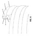
本開示は椎体の再建及び/又は椎間板交換に用いられ得る脊椎インプラントを特徴とする。一般的には、インプラントは拡張式コイルを備え、コイルは頂部及び底部を備え、かつ第1端部、第2端部、及び内腔部を画定する側壁を有する中空管から形成される。第1端部及び/又は第2端部は開放されていてもよく、閉鎖されていてもよい。コイルは中空管から形成された複数の環を含み、また垂直方向に隣接する環はこれらの対応する下部側壁と上部側壁との間に空間を有する。したがって、コイルは複数の環及び複数の空間を備える。 The present disclosure features spinal implants that can be used for vertebral body reconstruction and / or disc replacement. Generally, an implant comprises an expandable coil, the coil being formed from a hollow tube having a top and a bottom and having a first end, a second end, and a sidewall defining a lumen. The first end and / or the second end may be open or closed. The coil includes a plurality of rings formed from hollow tubes, and the vertically adjacent rings have a space between their corresponding lower and upper sidewalls. Accordingly, the coil includes a plurality of rings and a plurality of spaces.
いくつかの態様では、インプラントは側壁を貫いて内腔部に延在する複数の開孔部を備える。いくつかの態様では、インプラントは複数の開孔部の代わりに、側壁を貫いて内腔部に延在する間隙を備える。間隙は第1端部から第2端部へと長手方向に延在し、環内に形成された管の上部又は下部表面のいずれかに存在する。 In some aspects, the implant includes a plurality of apertures extending through the sidewalls to the lumen. In some embodiments, the implant includes a gap extending through the sidewall and into the lumen instead of a plurality of apertures. The gap extends longitudinally from the first end to the second end and is present on either the upper or lower surface of the tube formed in the annulus.
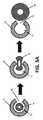
インプラントは全体に散在する少なくとも1つのバルーンを備え得、その結果上下に隣接した環の間の空間を占める。いくつかの態様では、バルーンは、配置されるまでは内腔部内に収容される。バルーンは、内腔部から間隙を通して、上下に隣接した環の間の空間に配置され得る。上下に隣接した環の間の空間内にあり、かつ充填されているとき、バルーンはコイルの環を上下方向に押し離して、その結果コイルを拡張する。例えば、バルーンがその外方向の最大容量まで充填及び拡張するために、バルーンはバルーンの真上にある環の下部表面を押して下部表面(及び環)を上方に押し上げ、またバルーンはバルーンの真下にある環の上部表面を更に押して上部表面(及び環)を下方に押し上げる。コイルが拡張されるとき、インプラントは椎間板の高さ、及び/又は椎体の高さに近い高さを有し、いくつかの態様では、2つの椎骨及び少なくとも1つの円板(例えば脊椎運動セグメント又は機能的脊椎単位)の高さに近い高さを有する。いくつかの態様では、脊椎運動セグメントは2つの隣接する椎体、これらの関節突起によって作られる椎間関節、これらの間の椎間板及び付随する軟組織を備える。椎間板及び椎間関節(正中線の各側面上にあるもの)は、運動セグメントレベルでの屈曲、伸長、側部曲げ、及び回転運動を可能にする。少なくとも1つのバルーンは柔軟、半柔軟、又は非柔軟であり得る。 The implant may comprise at least one balloon interspersed throughout, so that it occupies the space between the upper and lower adjacent rings. In some aspects, the balloon is housed within the lumen until deployed. Balloons can be placed in the space between the upper and lower adjacent rings from the lumen through the gap. When in the space between the upper and lower adjacent rings and filled, the balloon pushes the coil ring up and down, thereby expanding the coil. For example, in order for the balloon to fill and expand to its maximum outward volume, the balloon pushes the lower surface of the annulus just above the balloon to push the lower surface (and the ring) upward, and the balloon is just below the balloon Push the upper surface of a ring further to push the upper surface (and the ring) down. When the coil is expanded, the implant has an intervertebral disc height and / or a height close to that of the vertebral body, and in some embodiments, two vertebrae and at least one disc (eg, a spinal motion segment). (Or functional spinal unit). In some aspects, the spinal motion segment comprises two adjacent vertebral bodies, a facet joint created by these articular processes, an intervertebral disc between them, and accompanying soft tissue. Intervertebral discs and facet joints (on each side of the midline) allow flexion, extension, side bending, and rotational motion at the motion segment level. The at least one balloon can be flexible, semi-flexible, or inflexible.
中空管は、形状記憶能力を有して、応力誘引性の超弾性、及び最大8〜10%歪みの可逆的変形性を付与する金属を含む可撓性金属からなり得る。好適な金属としてはチタン、鋼鉄、アルミニウム、又はニチノールなどの合金が挙げられる。 The hollow tube can be made of flexible metals including metals that have shape memory capability, impart stress-induced superelasticity, and reversible deformability of up to 8-10% strain. Suitable metals include titanium, steel, aluminum, or alloys such as nitinol.
骨移植材料又は骨セメントは、内腔部内に存在し得るか又は第1端部に着脱自在に接続され、かつ骨移植材料又は骨セメントの供給源に作動可能に更に接続される工具によって内腔部に導入され得る。したがって、工具は骨移植材料又は骨セメントを供給源から取り、続いてインプラントの内腔部に挿入し得る。骨移植材料は、海綿状自家移植骨片、同種移植骨片、脱灰骨基質(DBM)、骨形態形成蛋白質(BMP)、又はこれらの任意の組み合わせであり得る。骨セメントはリン酸カルシウム又はヒドロキシアパタイトを含み得る。 The bone graft material or bone cement can be in the lumen or can be removably connected to the first end and can be lumened by a tool that is further operatively connected to a source of bone graft material or bone cement. Can be introduced into the department. Thus, the tool can take bone graft material or bone cement from the source and subsequently insert it into the lumen of the implant. The bone graft material can be a spongy autograft bone piece, an allograft bone piece, demineralized bone matrix (DBM), bone morphogenic protein (BMP), or any combination thereof. The bone cement can include calcium phosphate or hydroxyapatite.
いくつかの態様では、インプラントは2つ、3つ、4つ、5つ、6つ、7つ、8つ、又はそれ以上を含む複数のバルーンを含む。これらのバルーンは、かかるバルーンが内腔部から配置された後を含み、各環の間の空間全体に散在され、かつこの空間を占める。バルーンのうちのいずれかは、単一のチャンバ又は複数のチャンバを含み得る。バルーンは、バルーンを充填するために空気又は流体をチャンバ内に入れる開口部を更に含む。工具は開口部に着脱自在に接続され得、この工具は空気又は流体の供給源に作動可能に更に接続され得る。バルーンに注入を含む挿入をされる流体は、水、食塩液、造影剤、水素、ヒドロゲル、又は骨セメントを含み得る。バルーンチャンバに挿入されるとき流体は液状であり得、また、インプラントの移植時に一旦バルーン及び/又は体内に挿入されると、重合可能、結晶化可能、又は凝固可能である。1つ又は複数のバルーンは接着剤によって環に取り付けられ得るが、いくつかの態様では接着剤は用いられない。 In some aspects, the implant includes a plurality of balloons including two, three, four, five, six, seven, eight, or more. These balloons are interspersed and occupy the entire space between each ring, including after such balloons are placed from the lumen. Any of the balloons may include a single chamber or multiple chambers. The balloon further includes an opening that allows air or fluid into the chamber to fill the balloon. The tool can be removably connected to the opening, and the tool can be further operably connected to a source of air or fluid. The fluid to be inserted including injection into the balloon may include water, saline, contrast media, hydrogen, hydrogel, or bone cement. The fluid can be liquid when inserted into the balloon chamber and can be polymerized, crystallized, or solidified once inserted into the balloon and / or body during implantation of the implant. One or more balloons may be attached to the ring by an adhesive, but in some embodiments no adhesive is used.
本開示は、椎体の増強又は再建方法と、椎間板の修復又は交換方法と、脊椎運動セグメントの再建方法と、を更に特徴とする。方法は、本明細書に記載又は例示された任意のインプラントなどのインプラントを椎体(例えば、それによって椎骨が除去される椎体切除手術によって作られた垂直体(vertical body)内の空隙)若しくは椎間腔又は除去された脊椎運動セグメントにインプラントすることと、内腔部からバルーンを配置する及び/又はコイルを拡張してインプラントの高さを所望の高さまで増加させるのに十分な量の流体でバルーンを充填することと、任意で複数の開孔部若しくは間隙並びに/又は第1及び第2開口部から椎体又は椎間腔に骨移植材料又は骨セメントを配置することと、任意で椎体又は椎間腔から拡張式コイルを除去することと、を一般に含む。骨移植材料又は骨セメントが配置された場合は、骨移植材料又は骨セメントを配置した後で、コイルは椎体又は椎間腔から除去されてもよい。 The disclosure further features a vertebral body augmentation or reconstruction method, a disc repair or replacement method, and a spinal motion segment reconstruction method. The method may include implanting an implant, such as any of the implants described or exemplified herein, with a vertebral body (eg, a void in a vertical body created by a vertebral body excision by which a vertebra is removed) or A sufficient amount of fluid to implant into the intervertebral space or removed spinal motion segment and to place the balloon from the lumen and / or expand the coil to increase the height of the implant to the desired height Filling the balloon, optionally placing a bone graft material or bone cement from the plurality of apertures or gaps and / or the first and second openings into the vertebral body or intervertebral space, and optionally the vertebrae. Removing the expandable coil from the body or intervertebral space. If a bone graft material or bone cement is deployed, the coil may be removed from the vertebral body or intervertebral space after placing the bone graft material or bone cement.
本開示は、以下の詳細な説明を添付図面と引き合わせながら読むことで最もよく理解できる。図面の様々な特徴は、慣行に従い縮尺通りではないことを強調する。その上、様々な特徴の寸法は、明確さのために任意に拡大又は縮小される。図面には以下の図が含まれる。
本開示の態様に関連する様々な用語が、本明細書及び特許請求の範囲を通して用いられる。かかる用語は特に指示のない限りは当該技術分野の一般的な意味を有する。その他の具体的に定義される用語は、本文献で与えられる定義と一致する方法で解釈される。 Various terms related to aspects of the disclosure are used throughout the specification and the claims. Such terms have their ordinary meaning in the art unless otherwise indicated. Other specifically defined terms are construed in a manner consistent with the definitions given in this document.
本明細書を通じて用いられるとき、単数形「a」、「an」、及び「the」は、別段の明確な指示がない限り、複数の指示対象を含む。 As used throughout this specification, the singular forms “a”, “an”, and “the” include plural referents unless the content clearly dictates otherwise.
用語「被験者」及び「患者」は同じ意味で用いられる。患者は、コンパニオンアニマル、実験動物、非ヒト霊長類などの哺乳類を含む任意の動物であり得る。ヒトが好ましい。 The terms “subject” and “patient” are used interchangeably. The patient can be any animal including mammals such as companion animals, laboratory animals, non-human primates. Human is preferred.
本開示は、椎間板を交換若しくは再建する、椎体などの椎骨の少なくとも1部分を交換若しくは再建する、又はこれを必要とする患者の脊椎運動セグメントを交換又は再建するための装置、システム、方法を特徴とする。装置、システム、及び方法は、例えば脊椎再建、修復、又は固定手術に用途を見出し得る。基本的な特徴は、コイルの空間全体に散在するバルーンを有する拡張式コイルである。椎体の再建にはより大きな拡張式コイルが用いられ得る。円板交換のための椎間腔により小さな拡張式コイルが用いられ得る。少なくとも2つの椎体及び少なくとも1つの椎間板に及ぶ脊椎運動セグメントの再建には、更に大きな拡張式コイルが用いられ得る。 The present disclosure provides an apparatus, system, and method for exchanging or rebuilding a disc, replacing or rebuilding at least a portion of a vertebra such as a vertebral body, or replacing or rebuilding a spinal motion segment of a patient in need thereof. Features. The device, system, and method may find application in, for example, spinal reconstruction, repair, or fixation surgery. The basic feature is an expandable coil with balloons scattered throughout the coil space. Larger expandable coils can be used for vertebral body reconstruction. Small expandable coils can be used in the intervertebral space for disc replacement. Larger expandable coils can be used to reconstruct spinal motion segments that span at least two vertebral bodies and at least one intervertebral disc.
拡張式コイルの構成要素は、任意の好適な材料又は材料の組み合わせから製造可能である。材料しては、好ましくは医療又は外科グレードの、好ましくは生体適合性のプラスチック、ポリマー、金属、及び複合材、並びに天然又は合成骨が挙げられる。好適なポリマーの比限定的な例としては、ポリエーテルエーテルケトン(PEEK)、ポリアミンイミド(PAI)、ポリエチレンイミン(PEI)、ポリフェニルスルホン(PPSU)、ポリオキシメチレン(POM)、及び超高分子量ポリエチレン(UHMW−PE)が挙げられる。好適な金属の比限定的な例としては、チタン、タンタル、アルミニウム、外科グレードの鋼鉄、並びにニチノール(ニッケル−チタン合金)、Ti−6Al−4V(TAV)、及びTi−6Al−7Nb(TAN)などのチタン合金並びにコバルトクロム合金を含む合金が挙げられる。ニチノールが好ましい。炭素はインプラントコイルの少なくとも一部を製造するために更に用いられ得る。好ましくは、コイルが拡張し得るように、材料は十分に可撓性である。 The components of the expandable coil can be manufactured from any suitable material or combination of materials. Materials include preferably medical or surgical grade, preferably biocompatible plastics, polymers, metals, and composites, and natural or synthetic bone. Specific examples of suitable polymers include polyetheretherketone (PEEK), polyamineimide (PAI), polyethyleneimine (PEI), polyphenylsulfone (PPSU), polyoxymethylene (POM), and ultra high molecular weight A polyethylene (UHMW-PE) is mentioned. Specific examples of suitable metals include titanium, tantalum, aluminum, surgical grade steel, and nitinol (nickel-titanium alloy), Ti-6Al-4V (TAV), and Ti-6Al-7Nb (TAN). And alloys including titanium alloys and cobalt chromium alloys. Nitinol is preferred. Carbon can further be used to produce at least a portion of the implant coil. Preferably, the material is sufficiently flexible so that the coil can expand.
図を参照すると、図面を含む様々な図を通じて参照番号が同様の構成要素を示し、図1は拡張式コイルインプラント10の例を示す。コイル状インプラント10は頂部12及び底部14並びに複数の拡張式環16を含む。インプラント10はコイルであり、コイル状インプラント10は環16の間に散在する複数の空間18を更に含む。空間18は隣接する環16の間に垂直に配向される。例えば、各環16は上部表面、下部表面、外部表面、及び内部表面を有する側壁20を備え、各空間18は環16の下部表面の真下かつ垂直表面内で環16に最も近い環16の上部表面の真上に位置する。空間18は水平方向に隣接する環の間ではなく垂直方向に隣接する環の間にあり、中央空隙19は水平方向に隣接する環の間にある。コイル状インプラント10は一般に頂部12に位置する第1端部11及び一般に底部14に位置する第2端部13を含む。第1端部11及び第2端部13は点を含み得るか又は平坦であり得、これらはそれぞれ鈍角であることが好ましい。第1端部11及び第2端部13は、例えばインプラント10を所定の位置に保持するために、椎骨に係合して食い込む縁部、返し部、又は突起部を含み得る。 Referring to the drawings, like numerals indicate like components throughout the various views, including the drawings, and FIG. 1 illustrates an example of an
コイル状インプラント10環16は好ましくは中空であり、そのため内腔部22を包囲する管状側壁20を備える(図5a及び5b)。管状側壁20は実質的に円形、楕円形、四角形、五角形、六角形、七角形又は八角形を含み得るが、任意の数の側面を有する形状が用いられ得る。図1は実質的に円形の側壁20を示す。いくつかの態様では、インプラント10は、側壁20を貫通して内腔部22内に通じる複数の開孔部24を更に含み得る。更に、いくつかの態様では、第1端部11及び第2端部13のうちの少なくとも1つが開口部15、17を含み得る。 The
第1工具100は、インプラント10の第1端部11又は第2端部13のいずれか又は両方に着脱自在に係合し得る。第1工具100は罠又はスネアを含み得るか、又は単に開口部15又は17上又は内への摩擦嵌合を含む嵌合がなされるように適合的に形成され得る。第1工具100はポンプを含み得るか、又は骨移植材料の供給源及び/又は空気若しくは流体の供給源に作動可能に接続され得る。 The
いくつかの態様では、インプラント10は側壁20を貫通する複数の開孔部24を含まない。その代わりに、かかる態様では、側壁20は側壁20を貫通して内腔部22内に通じる間隙26を備える。間隙26は、インプラント10の実質的な全長を通り、例えば、間隙は第1端部11から第2端部13に延在する。間隙26は環16の側壁20の上部、下部、外部、又は内部表面のいずれの上にあってもよい。好ましくは、間隙26は側壁20の上部表面又は下部表面のいずれかの上に存在する。図6は側壁20の下部表面上の間隙26の例を示す。 In some aspects, the
いくつかの態様では、環16間の空間18は、好ましくはバルーン30又は膜30によって占められる。この実施形態の一例を図2に示す。バルーン30又は膜30は、垂直方向に隣接する環16の側壁20の間に例えば摩擦嵌合によって挟まれ得、及び/又は接着剤によって側壁20に取り付けられ得る。 In some embodiments, the
いくつかの態様では、バルーン30又は膜30は、当初、例えば移植手術それ自体の間は空間18内に存在しない。かかる態様では、バルーン30又は膜30はインプラント10の内腔部22内に収容され、一旦インプラント10が椎骨又は椎間腔内の所望の位置に設置されると、内腔部22から空間18内に配置される。内腔部22内に収容される間、バルーン30又は膜30は実質的に膨張していないことが好ましい。かかる態様では、インプラント10は間隙26を含み、バルーン30又は膜30は内腔部22から間隙26を通ってインプラント10の空間18内に配置される。例えば図6を参照されたい。間隙26は任意の好適な幅を含み得る。例えば図5A及び5Bを参照されたい。バルーン30又は膜30は、本明細書に記載される通り、例えば空気又は流体でこれを充填することによって配置され得る。バルーン30又は膜30の充填によって、バルーン30又は膜30は、それが充填され続ける間隙26から押し出され、続いて空間18内に挟まれ、続いてそれにより垂直方向に隣接する環16の上部及び下部表面と接触し、続いてこれが充填され続けると、垂直方向に隣接する環16をそれぞれ上方及び可能に押して、それによってコイルを拡張させる。 In some embodiments, the
第2工具200は、バルーン30又は膜30が内腔部22、空間18、及び/又は中央空隙19内にあろうと、バルーン30又は膜30の開放端に着脱自在に係合し得る。第2工具200は、可撓性プラスチック若しくはゴム製管、又は更にはより剛性の高い金属製管を含む管を含み得る。例えば、かかる管は、バルーン30又は膜30上の開口部に摩擦嵌合を含む係合をし得る。第2工具200はポンプを含み得るか、及び/又は空気又は流体の供給源に作動可能に接続され得る。 The
第1工具100はインプラント10を保持する(例えば椎体内におけるその所望の位置に、又は椎間腔内にコイル状インプラント10を設置する)ために用いられ得る。第1工具100は、インプラント10をその所望の位置に配置するために、インプラント10を移動させるためにも更に用いられ得る。いくつかの態様では、第1工具100は骨移植材料又は骨セメントを第1端部11又は第2端部13を通してインプラント10の内腔部22に送達するために用いられ得る。例えば、骨移植材料は第1工具100を通して、続いて第1工具100が取り付けられるコイル状インプラント10の開口部15又は17を通して(第1工具100が第1端部11又は第2端部13のいずれに取り付けられているかに応じて)押し出され得る。続いて骨移植材料又は骨セメントは内腔部22に入って貫き、複数の開孔部24又は間隙26を通して、内腔部22及び第1工具100と接続されていない開口部15又は17から出得る。したがって、複数の開孔部24及び開口部15又は17は骨移植材料又は骨セメントを配置する。いくつかの態様では、間隙26は骨移植材料又は骨セメントを配置するために用いられ得る。 The
1つを超えるバルーン30又は膜30が用いられ得る。バルーン30又は膜30は任意の好適な材料から製造され得る。例えば、材料は生体適合性プラスチック、ポリマー、ゴム、複合材、ホイル、又はこれらの組み合わせを含み得る。バルーン30又は膜30は例えば柔軟又は半柔軟であり得、充填時に拡張し得る。バルーン30又は膜30は例えば非柔軟であり得、充填時に実質的に拡張し得ないが、かかる非柔軟バルーン30又は膜30は、折り畳まれた場合は開かない場合がある。バルーン30又は膜30は単一の容積又は複数の容積を含む場合があり、例えば後者の場合では、バルーン30又は膜30は充填され得る複数のチャンバを有する場合がある。バルーン30又は膜30は、それを通してチャンバを充填するために流体又は空気を挿入可能な各チャンバと連通する少なくとも1つの開口部を含む。バルーン30又は膜30が所望のレベルまで充填されると、開口部は例えばストッパ、タイ、接着剤、シール、はんだ、又はその他の好適なクロージャを用いて閉鎖され得る。開口部は自己密封式バルブを含むバルブを備え得る。 More than one
バルーン30又は膜30は、例えば好適な量の空気又は流体で充填され得る。例えば、バルーン30又は膜30が拡張して、それによってインプラント10の挿入及び配置の間にバルーン30又は膜30が環内空間18内の定位置に保持されるように、バルーン30又は膜30は空気又は流体で少なくとも部分的に充填され得る。一旦インプラント10が椎体又は椎間腔内の所望の位置に位置すると、バルーン30又は膜30は、バルーン30又は膜30を更に拡張させる追加の空気又は液体を充填され得る。バルーン30又は膜30は、充填されて拡張するとコイルの隣接する環16に対して外方に向かう圧力を働かせ、それによって環16を軸Xを中心に上方向/下方向へと互いに引き離す。環16が拡張して離れると、インプラント10の高さHは増加する。インプラント10の高さHが増加することで、インプラント10の椎骨間の嵌合が改善され、椎間腔の円板代替品として用いられるときは隣接する椎骨の端板間の所望の距離を定めて、例えば、従前は天然の円板によって占められていた天然の距離を復元するか、又は脊柱前湾の角度を定める。
バルーン30又は膜30及び環16は連携して、インプラント10の中心部19を本質的に「ウォールオフ」し得、ここで中心部19は本質的に環16及び空間18によって包囲される空隙19であり、この空間18はバルーン30又は膜30によって占められ得る。したがって、いくつかの態様では、例えば開孔部24及び/又は開口部15若しくは17を通して配置される材料である骨移植材料は、環16の内部表面とバルーン30又は膜の内部表面との間に収容される空隙19を充填し得、かつ椎骨に接触し得、またいくつかの態様では、隣接する椎骨の骨に接触する。
いくつかの代替的な実施形態では、バルーン30又は膜30はコイルの中心にある空隙19の少なくとも1部分内にも更に存在する。したがって、バルーン30又は膜30はコイル状インプラント10の中心部19の一部又は全部を占め得る。かかるバルーン30又は膜30は、環16の間の空間18のうちの少なくとも1つ内に更に存在し得、又は、バルーン30又は膜30は環16の間の空間18のいずれをも占め得ず、かつコイルを構成する複数の環16によって本質的に閉じ込められる。 In some alternative embodiments, the
骨移植材料は天然であっても又は合成であってもよく、また、海綿状自家移植骨片、同種移植骨片、コラーゲンヒドロキシアパタイト、脱灰骨基質(DBM)、多孔質の合成代用骨移植片、骨形態形成蛋白質(BMP)、又はこれらの組み合わせを含み得る骨成長及びオッセオインテグレーションを促進する任意の材料が用いられ得る。骨移植材料はペースト、パテ、又はスラリー状であり得る。骨移植材料は成長因子を含み得る。多数の骨移植材料が市販されており、またインプラント10に関する使用に好適である。 The bone graft material may be natural or synthetic, and can also be spongy autograft bone, allograft bone, collagen hydroxyapatite, demineralized bone matrix (DBM), porous synthetic bone graft. Any material that promotes bone growth and osseointegration, which may include a piece, bone morphogenetic protein (BMP), or a combination thereof may be used. The bone graft material can be in the form of a paste, putty or slurry. The bone graft material can include a growth factor. A number of bone graft materials are commercially available and are suitable for use with the
バルーン30又は膜30は、バルーン30又は膜の開放端に取り付けられ得、それによって空気又は流体をバルーン30又は膜30チャンバに送達し得る第2工具200によって充填され得る。流体は生理食塩水、放射線不透過造影剤(adiopaque contrast solution)を含み得、又は水を含み得、又はヒドロゲルを含み得、又は重合性モノマー若しくはポリマーを含み得、又は骨セメントを含み得、又は結晶化性材料を含み得る。骨セメントの非限定的な例には、リン酸カルシウム(CaP)及び/又はヒドロキシアパタイトが含まれる。好ましくは、流体は生体適合性である。好ましくは、流体は緩衝作用を提供し、更に例えば被験者が物体を移動させる又は持ち上げるなどの脊椎の運動による負荷力のうちの一部に耐え得る。椎骨再建の場合、流体は骨セメントであり得、より低い緩衝作用を提供し、またより高い耐荷重機能を提供する。流体はポリメチルメタクリレート(PMMA)を含み得る。バルーンチャンバに挿入されるとき、流体は液状であり得、インプラントの移植時に一旦バルーン及び/又は体内に挿入されると重合可能、結晶化可能、又は凝固可能である。 The
コイル状インプラント10は高さHを含む(図1及び図2)。拡張した又は未拡張のインプラント高さHは、頂部12の表面から底部14の表面まで測定されることが好ましい。椎骨再建のためのコイル状インプラント10は、実質的に再建される椎体の高さと近似する、比較的高い高さHを有し得る。円板交換のためのコイル状インプラント10は、実質的に交換される円板の高さと近似する、比較的低い高さHを有し得る。 The
円板交換に用いられる未拡張のコイル状インプラント10(例えば椎間のコイル状インプラント10)の高さHは、約5mm〜約20mmであり得る。いくつかの態様では、未拡張の円板交換インプラントの高さHは、約5mm〜約10mm、約5mm〜約12mm、約5mm〜約14mm、約5mm〜約15mm、約5mm〜約16mm、約5mm〜約18mm、約5mm〜約20mm、約7mm〜約mm、約7mm〜約12mm、約7mm〜約4mm、約7mm〜約5mm、約7mm〜約6mm、約7mm〜約8mm、約7mm〜約20mm、約9mm〜約12mm、約9mm〜約14mm、約9mm〜約15mm、約9mm〜約16mm、約9mm〜約18mm、約9mm〜約20mm、約10mm〜約12mm、約10mm〜約14mm、約10mm〜約15mm、約10mm〜約6mm、約10mm〜約8mm、約10mm〜約20mm、約11mm〜約3mm、約12mm〜約14mm、約12mm〜約15mm、約12mm〜約16mm、約12mm〜約18mm、約12mm〜約20mm、約13mm〜約15mm、約14mm〜約16mm、約14mm〜約18mm、約14mm〜約20mm、約15mm〜約17mm、約15mm〜約18mm、又は約15mm〜約20mmである。未拡張のインプラントの高さは5mm未満、又は20mm超であり得る。 The height H of the unexpanded coiled implant 10 (eg, intervertebral coiled implant 10) used for disc replacement may be between about 5 mm and about 20 mm. In some aspects, the height H of the unexpanded disc replacement implant is about 5 mm to about 10 mm, about 5 mm to about 12 mm, about 5 mm to about 14 mm, about 5 mm to about 15 mm, about 5 mm to about 16 mm, about 5 mm to about 18 mm, about 5 mm to about 20 mm, about 7 mm to about mm, about 7 mm to about 12 mm, about 7 mm to about 4 mm, about 7 mm to about 5 mm, about 7 mm to about 6 mm, about 7 mm to about 8 mm, about 7 mm to About 20 mm, about 9 mm to about 12 mm, about 9 mm to about 14 mm, about 9 mm to about 15 mm, about 9 mm to about 16 mm, about 9 mm to about 18 mm, about 9 mm to about 20 mm, about 10 mm to about 12 mm, about 10 mm to about 14 mm About 10 mm to about 15 mm, about 10 mm to about 6 mm, about 10 mm to about 8 mm, about 10 mm to about 20 mm, about 11 mm to about 3 mm, about 12 mm to about 1 mm, about 12 mm to about 15 mm, about 12 mm to about 16 mm, about 12 mm to about 18 mm, about 12 mm to about 20 mm, about 13 mm to about 15 mm, about 14 mm to about 16 mm, about 14 mm to about 18 mm, about 14 mm to about 20 mm, About 15 mm to about 17 mm, about 15 mm to about 18 mm, or about 15 mm to about 20 mm. The height of the unexpanded implant can be less than 5 mm or greater than 20 mm.
拡張したインプラント10は、頚椎間板、胸椎間板、腰椎間板又は仙椎間板を含む交換される椎間板の高さに近い場合がある。一旦拡張されると、円板交換に用いられるコイル状インプラント10の高さHは、約5mm〜約35mmであり得る。いくつかの態様では、拡張円板交換インプラントの高さHは、約7.5mm〜約10mm、約7.5mm〜約12mm、約7.5mm〜約14mm、約7.5mm〜約15mm、約7.5mm〜約16mm、約7.5mm〜約18mm、約7.5mm〜約20mm、約7.5mm〜約25mm、約7.5mm〜約27mm、約7.5mm〜約30mm、約9mm〜約12mm、約9mm〜約15mm、約8mm〜約16mm、約8mm〜約8mm、約8mm〜約20mm、約9mm〜約22mm、約9mm〜約24mm、約9mm〜約25mm、約9mm〜約30mm、約10mm〜約12mm、約10mm〜約14mm、約10mm〜約15mm、約10mm〜約6mm、約10mm〜約8mm、約10mm〜約20mm、約10mm〜約22mm、約10mm〜約24mm、約10mm〜約26mm、約10mm〜約28mm、約10mm〜約30mm、約12mm〜約16mm、約12mm〜約18mm、約12mm〜約20mm、約12mm〜約22mm、約12mm〜約24mm、約12mm〜約26mm、約12mm〜約30mm、約14mm〜約18mm、約14mm〜約20mm、約14mm〜約22mm、約14mm〜約24mm、約16mm〜約8mm、約16mm〜約20mm、約16mm〜約22mm、約16mm〜約24mm、約18mm〜約20mm、約18mm〜約22mm、約18mm〜約25mm、約20mm〜約22mm、約20mm〜約24mm、約22mm〜約26mm、又は約23mm〜約25mmである。未拡張のインプラント高さは5mm未満、又は35mm超であり得る。 The expanded
椎体又は脊椎運動セグメントの再建に用いられる未拡張のコイル状インプラント10(例えば、椎体コイル状インプラント10)の高さHは、約10mm〜約60mmであり得る。いくつかの態様では、高さHは約10mm〜約15mm、約10mm〜約20mm、約10mm〜約25mm、約10mm〜約30mm、約10mm〜約35mm、約10mm〜約40mm、約10mm〜約45mm、約15mm〜約20mm、約15mm〜約25mm、約15mm〜約30mm、約15mm〜約35mm、約15mm〜約40mm、約15mm〜約45mm、約20mm〜約25mm、約20mm〜約30mm、約20mm〜約35mm、約20mm〜約40mm、約20mm〜約45mm、約25mm〜約30mm、約25mm〜約35mm、約25mm〜約40mm、約25mm〜約45mm、約30mm〜約40mm、約30mm〜約45mm、又は約35〜約40mmであり得る。 The height H of an unexpanded coiled implant 10 (eg, vertebral body coiled implant 10) used for the reconstruction of a vertebral body or spinal motion segment may be from about 10 mm to about 60 mm. In some aspects, the height H is about 10 mm to about 15 mm, about 10 mm to about 20 mm, about 10 mm to about 25 mm, about 10 mm to about 30 mm, about 10 mm to about 35 mm, about 10 mm to about 40 mm, about 10 mm to about 45 mm, about 15 mm to about 20 mm, about 15 mm to about 25 mm, about 15 mm to about 30 mm, about 15 mm to about 35 mm, about 15 mm to about 40 mm, about 15 mm to about 45 mm, about 20 mm to about 25 mm, about 20 mm to about 30 mm, About 20 mm to about 35 mm, about 20 mm to about 40 mm, about 20 mm to about 45 mm, about 25 mm to about 30 mm, about 25 mm to about 35 mm, about 25 mm to about 40 mm, about 25 mm to about 45 mm, about 30 mm to about 40 mm, about 30 mm To about 45 mm, or about 35 to about 40 mm.
拡張インプラント10は、頚椎体、胸椎体、腰椎体又は仙椎体を含む再建される椎体又は脊椎運動セグメント、またいくつかの態様では、更に少なくとも1つの椎間板の高さに近い場合がある。一旦拡張されると、椎体再建に用いられるコイル状インプラント10の高さHは、約10mm〜約80mmであり得る。いくつかの態様では、拡張された高さHは約10mm〜約15mm、約10mm〜約20mm、約10mm〜約25mm、約10mm〜約30mm、約10mm〜約35mm、約10mm〜約40mm、約10mm〜約45mm、約10mm〜約50mm、約10mm〜約55mm、約10mm〜約60mm、約10mm〜約70mm、約15mm〜約20mm、約15mm〜約25mm、約15mm〜約30mm、約15mm〜約35mm、約15mm〜約40mm、約15mm〜約45mm、約15mm〜約50mm、約15mm〜約55mm、約15mm〜約60mm、約15mm〜約70mm、約20mm〜約25mm、約20mm〜約30mm、約20mm〜約35mm、約20mm〜約40mm、約20mm〜約45mm、約20mm〜約50mm、約20mm〜約55mm、約20mm〜約60mm、約20mm〜約65mm、約25mm〜約30mm、約25mm〜約35mm、約25mm〜約40mm、約25mm〜約45mm、約25mm〜約50mm、約25mm〜約55mm、約30mm〜約40mm、約30mm〜約45mm、約30mm〜約50mm、約30mm〜約45mm、約35mm〜約40mm、約35mm〜約45mm、約35mm〜約50mm、又は約35mm〜約60mmであり得る。 The
一旦バルーン30又は膜30が充填されると、インプラント高さHは最大で約100%増加し得、又はいくつかの態様では、最大約125%、最大約150%、又は最大約175%増加し得る。好ましくは、インプラント高さHは未拡張の高さHと比較して約10%〜約50%増加する。インプラント高さHは、未拡張の高さHと比較して約10%〜約40%、約10%〜約33%、約10%〜約30%、約10%〜約25%、約10%〜約20%、約10%〜約15%、約15%〜約45%、約15%〜約40%、約15%〜約33%、約15%〜約30%、約15%〜約25%、約15%〜約20%、約20%〜約50%、約20%〜約40%、約20%〜約33%、約20%〜約30%、約20%〜約25%、約25%〜約50%、約25%〜約40%、約25%〜約33%、約25%〜約30%、約50%〜約0.5%、約30%〜約40%、又は約40%〜約50%増加し得る。いくつかの態様では、インプラント高さHは、その未拡張の高さHと比較して約10%、約15%、約20%、約25%、約30%、約35%、約40%、約45%、約50%、約55%、約60%、約65%、約70%、約75%、約80%、約85%、約90%、約95%、約100%、又はそれ以上増加する。 Once the
いくつかの態様では、コイル状インプラント10は、インプラント10の1側面の高さHがインプラント10の対向面の高さHよりも大きくなるように、前弯角を含む。より大きな高さH及びより小さな高さHは、本明細書に記載又は例示されるサイズを独立して含み得る。 In some aspects, the coiled
コイル状インプラント10は、好ましくは実質的に均一な幅Wを有する。幅は、インプラント10の1側面上の環16の外部表面からインプラント10の対向する側面上の環16の外部表面まで測定され得る。コイル状インプラント10が実質的に円形状を備える実施形態では、幅Wは直径を備える。コイル状インプラントは、長円形、楕円形、又は更には不規則形を含む非円形を含み得る。 The
インプラント幅Wは約10mm〜約70mmであり得る。いくつかの態様では、幅Wは約10mm〜約20mm、約10mm〜約25mm、約10mm〜約30mm、約10mm〜約35mm、約10mm〜約40mm、約10mm〜約45mm、約10mm〜約50mm、約10mm〜約65mm、約15mm〜約20mm、約15mm〜約25mm、約15mm〜約30mm、約15mm〜約35mm、約15mm〜約40mm、約15mm〜約45mm、約15mm〜約50mm、約15mm〜約55mm、約15mm〜約60mm、約15mm〜約65mm、約15mm〜約70mm、約20mm〜約25mm、約20mm〜約30mm、約20mm〜約35mm、約20mm〜約40mm、約20mm〜約45mm、約20mm〜約50mm、約20mm〜約60mm、約20mm〜約65mm、約20mm〜約70mm、約25mm〜約30mm、約25mm〜約35mm、約25mm〜約40mm、約25mm〜約45mm、約25mm〜約50mm、約25mm〜約60mm、約30mm〜約35mm、約30mm〜約40mm、約30mm〜約45mm、約30mm〜約50mm、約30mm〜約60mm、約35mm〜約40mm、約35mm〜約45mm、約35mm〜約50mm、約35mm〜約55mm、約40mm〜約45mm、約40mm〜約50mm、約40mm〜約55mm、約45mm〜約50mm、約45mm〜約55mm、又は約45〜約60mmであり得る。10mmよりも短い又は70mmよりも長い幅Wが可能である。幅Wは椎骨の外側寸法を超えて延在しないことが好ましい。 The implant width W can be about 10 mm to about 70 mm. In some aspects, the width W is about 10 mm to about 20 mm, about 10 mm to about 25 mm, about 10 mm to about 30 mm, about 10 mm to about 35 mm, about 10 mm to about 40 mm, about 10 mm to about 45 mm, about 10 mm to about 50 mm. About 10 mm to about 65 mm, about 15 mm to about 20 mm, about 15 mm to about 25 mm, about 15 mm to about 30 mm, about 15 mm to about 35 mm, about 15 mm to about 40 mm, about 15 mm to about 45 mm, about 15 mm to about 50 mm, about 15 mm to about 55 mm, about 15 mm to about 60 mm, about 15 mm to about 65 mm, about 15 mm to about 70 mm, about 20 mm to about 25 mm, about 20 mm to about 30 mm, about 20 mm to about 35 mm, about 20 mm to about 40 mm, about 20 mm to About 45 mm, about 20 mm to about 50 mm, about 20 mm to about 60 mm, about 20 mm to about 6 mm, about 20 mm to about 70 mm, about 25 mm to about 30 mm, about 25 mm to about 35 mm, about 25 mm to about 40 mm, about 25 mm to about 45 mm, about 25 mm to about 50 mm, about 25 mm to about 60 mm, about 30 mm to about 35 mm, About 30 mm to about 40 mm, about 30 mm to about 45 mm, about 30 mm to about 50 mm, about 30 mm to about 60 mm, about 35 mm to about 40 mm, about 35 mm to about 45 mm, about 35 mm to about 50 mm, about 35 mm to about 55 mm, about 40 mm To about 45 mm, about 40 mm to about 50 mm, about 40 mm to about 55 mm, about 45 mm to about 50 mm, about 45 mm to about 55 mm, or about 45 to about 60 mm. A width W shorter than 10 mm or longer than 70 mm is possible. The width W preferably does not extend beyond the outer dimension of the vertebra.
いくつかの態様では、コイル状インプラント10が椎間腔に挿入するために用いられることが好ましい。したがって、一旦挿入されると、インプラント10の頂部12及び底部14は隣接する椎骨端板の骨と接触し、ここでインプラント10はこれらの隣接する椎骨端板の間の、従前は損傷した、病気にかかった、又は変性した円板によって占められていた空間に位置する。コイル状インプラント10は頚椎、胸椎、腰椎又は仙椎の椎間腔に挿入され得、高さHは、脊柱内のインプラントの意図された位置(例えば、脊椎の頚椎、胸椎、腰椎又は仙椎領域)に基づき得る。 In some aspects, the coiled
いくつかの態様では、コイル状インプラント10は椎体の三次元的再建のために用いられることが好ましい。したがって、一旦挿入されると、インプラント10の頂部12及び底部14は、椎体の欠損部分に近似し、ここでインプラント10は、椎体内の従前は損傷した、病気にかかった、又は変性した椎骨の部分によって占められていた空間に位置することが好ましい。コイル状インプラント10は、頚椎、胸椎、腰椎又は仙椎に挿入され得、高さHは骨の欠損部分に基づき得る。 In some embodiments, the coiled
いくつかの態様では、コイル状インプラント10は脊椎運動セグメントの三次元的再建のために用いられることが好ましい。したがって、一旦挿入されると、インプラント10の頂部12及び底部14は、2つの椎体及び少なくとも1つの椎間板の欠損部分に近似し、ここでインプラント10は、従前は損傷した、病気にかかった、又は変性した椎骨及び円板の部分によって占められていた空間内に位置することが好ましい。コイル状インプラント10は、頚椎、胸椎、腰椎又は仙椎、及びこれらの対応する椎間板の空間に挿入され得、高さHは骨及び円板の欠損部分に基づき得る。 In some embodiments, the coiled
インプラント10は脊椎固定手術の一部として身体内に挿入され得、又はいかなる固定工程にも参加せずに円板プロテーゼ形態として挿入され得る。この後者の場合、例えば、インプラント10は椎間腔を占めるが、新骨成長又は隣接する椎骨の固定を促進しない。固定されない場合、インプラント10は将来のある時点において椎間腔から除去され得る。脊椎固定手術の一部として用いられるとき、インプラント10は骨移植材料の送達工程を含み、新骨成長及びインプラント10のオッセオインテグレーションを促進するのはこの骨移植材料である。 The
いくつかの好ましい態様では、インプラント10の側壁20が製造される材料は、弾性を有し、形状記憶を更に備える。例えば、材料は被験者の身体外でコイルを形成するのに用いられ得、コイルは例えば、挿入手術の間にインプラントが通過する切り込みのサイズを最小化するために被験者に挿入するためにまっすぐに伸ばされるが、まっすぐに伸ばされたコイルは一旦身体に挿入されるとコイル形状に戻る。可撓性ワイヤを含むガイドワイヤが、非コイル状のインプラント10を円板の空間又は椎体内のその位置に誘導するために用いられ、そして一旦インプラント10が所望の位置に配置されると除去され得るが(and removed one the implant 10 is in a desired place,)、ガイドワイヤの除去によって、コイル状インプラント10が作られた原材料の形状記憶に基づいて再成形することが可能となる。 In some preferred embodiments, the material from which the
いくつかの態様では、インプラント10は温度記憶(例えば熱記憶)を備える。例えば、熱記憶を備えるインプラント10は、室温下でまっすぐに伸ばされ得るが、体温を含む加熱温度下ではコイル状になり得る。いくつかの態様では、インプラント10は超弾性記憶を備える。例えば、直線状の管(例えばニチノール)は高温(例えば480〜520℃)下で予めコイルに成形されて、続けて、例えば冷水内で急冷され得る。コイル状の管は非コイル状に引き伸ばされ、続いて直線状のカニューレ又はシースに挿入/固定され得るが、直線状のカニューレ又はシースから解放されると、管は管が製造された材料の超弾性記憶によって自動的に巻き直る。 In some aspects, the
コイル状形態又はまっすぐに伸ばされた形態(用いる場合はガイドワイヤを含む)のいずれであっても、インプラント10は、前方又は後方外科手術によって被験者の体内に挿入され得る。インプラント10は椎骨の前方、後方、側面、又は椎孔を通して挿入され得る。インプラント10は経椎弓根的(trans-pedicularly)に挿入され得る。 The
円板交換手術の間、損傷又は変性した椎間板の少なくとも1部分が除去され、いくつかの態様では円板全体が除去され得る。続いて椎間板空間はコイル状インプラント10を受容するように成形及び処理され得るが、これには必要であれば椎骨端板の骨の成形及び処理が含まれる。一旦椎間腔の準備が整えば、少なくとも1つのコイル状インプラント10が処理された椎間腔に挿入されてよい。コイル状インプラント10は非コイル状直線状管として、例えば、非コイル状インプラント10を直線状カニューレを通して体内に挿入されてもよく、ここでカニューレは体内に挿入される。続いてインプラント10はカニューレから解放され得、ここでインプラント10は巻き直る。巻き直りは、インプラント10を製造するために用いられた材料の熱記憶又は超弾性記憶に因り得る。 During disc replacement surgery, at least a portion of the damaged or degenerated disc can be removed, and in some embodiments the entire disc can be removed. Subsequently, the disc space may be shaped and processed to receive the coiled
椎体再建手術の間、損傷した又は病気にかかった椎体の少なくとも1部分が除去され(例えば椎体切除(copectomy))、いくつかの態様では椎体全体が除去され得る。続いて椎体の部分はコイル状インプラント10を受容するように成形及び処理され得る。一旦椎間腔の準備が整えば、少なくとも1つのコイル状インプラント10が処理された椎体の部分に挿入されてよい。コイル状インプラント10は非コイル状直線状管として、例えば、非コイル状インプラント10を直線状カニューレを通して体内に挿入されてもよく、ここでカニューレは体内に挿入される。続いてインプラント10はカニューレから解放され得、ここでインプラント10は巻き直る。巻き直りは、インプラント10を製造するために用いられた材料の熱記憶又は超弾性記憶に因り得る。 During vertebral body reconstruction surgery, at least a portion of the damaged or diseased vertebral body is removed (eg, copectomy), and in some embodiments the entire vertebral body can be removed. Subsequently, the portion of the vertebral body can be shaped and processed to receive the coiled
インプラント10挿入のための椎骨領域の処理には、窩洞形成手術が含まれ得る。かかる手術では、施術者は、例えば、窩洞形成バルーン(インプラント10のバルーン30ではない)を用いて海綿質骨を押すことにより、挿入標的部位を包囲する局部周辺に窩洞を形成する。一旦窩洞が形成されると、窩洞形成バルーンは収縮されて除去され、後に拡大された空間又は窩洞を残し得る。この窩洞により、カニューレを通した挿入を含むインプラント10の挿入に伴い得る抵抗が低減される。事実、窩洞はまっすぐに伸ばされたインプラント10を窩洞内でその熱又は超弾性記憶に基づき巻き直させるために用いられ得る。 Treatment of the vertebral region for
1つ超のコイル状インプラント10が椎間腔又は椎体に移植され得る。いくつかの態様では、1つのコイル状インプラント10が用いられ得るが、いくつかの態様では、2つ又は更には3つのインプラント10が移植され得る。コイル状インプラント10は椎骨端板の前側方又は後側方領域を含む椎骨端板の前方領域、後方領域、又は側方領域に配置され得る(例えば図3Aを参照されたい)。1つ超のインプラント10が用いられる場合、1つのインプラント10は前方領域内に配置され得、第2インプラント10は後方領域内に配置され得(例えば図3Bを参照されたい)、又は、1つのインプラント10は1つの側方領域に配置され得、第2インプラント10は対向する側方領域内に配置され得る。 More than one coiled
一旦インプラント10が所定の位置に配置されると、バルーン30又は膜30は所望のレベルの空気又は流体で充填され得、その結果、バルーン30又は膜30が触れる環16を押すことによってコイルの高さHを拡張して、インプラント10の軸Xを中心に上方及び下方に移動させる。軸Xは、被験者の脊椎(例えば直立歩行するヒトの脊椎)の垂直配向に近いことが好ましい。いくつかの態様では、例えば、被験者が四足歩行動物である場合、軸Xは被験者の脊椎の水平配向に近似し得る。空気又は流体は第2工具200によって供給され得る。 Once the
いくつかの態様では、一旦インプラント10が所定の位置に配置されたが、バルーン30又は膜30が空気又は流体で充填される前に、インプラント10のコイリング(非コイル状で挿入された場合はその場でのコイリング)及び/又は配置が、例えば、バルーンを恒久的な空気又は流体で充填することにより及び/又は骨移植材料又は骨セメントを配置することにより、永続性が確率される前に視覚化及び確認され得るように、バルーン30又は膜30は放射線造影剤などの造影剤で充填され得る。造影剤によるバルーン30又は膜30の充填は、バルーン30又は膜が間隙26から及び/又は空間18へと適切に配置することの視覚化及び確認に更に用いられ得る。造影剤は、バルーン30又は膜30が空気又は流体で充填される前にバルーン30又は膜30から除去されることが好ましい。 In some aspects, once the
空気又は流体のレベルは、適切に復元された椎間腔の高さ又は適切に再建された椎体の高さを含む被験者の必要に従って変化し得る。いくつかの態様では、1つ超のバルーン30又は膜30がコイル状インプラント10内に存在するか、又は1つ超のチャンバを有する単一のバルーン30又は膜30がコイル状インプラント内に存在する。かかる態様では、第1のバルーン30若しくは膜30又はバルーン30若しくは膜30の第1のチャンバはあるレベルまで充填されてもよく、また、少なくとも第2のバルーン30若しくは膜30又はバルーン30若しくは膜の第2のチャンバは、椎間腔内に前弯角を確立するように、第1のバルーン30若しくは膜又は第1のチャンバのレベルよりも大きいか又は小さい別のレベルまで充填されてもよい。言い換えれば、あるレベルまで充填された一方のバルーン30若しくは膜30、又は単一のバルーン30若しくは膜30の一方のチャンバ、及び別のレベルまで充填されたもう一方のバルーン30若しくは膜、又は単一のバルーン30若しくは膜30のもう一方のチャンバによって、コイル状インプラント10の拡張された高さHは少なくとも側面で異なり、これらの側面間の高さHにおけるこの差異が所望の前弯角を確立する。 The air or fluid level may vary according to the subject's needs, including the properly restored intervertebral space height or the properly reconstructed vertebral body height. In some aspects, more than one
バルーン(単数又は複数)30又は膜(単数又は複数)30の充填の前、後、又はそれと同時に、骨移植材料はインプラント10から配置され得る。例えば、骨移植材料は、例えば第1工具100によって開口部15又は17に挿入されて内腔部22に入り複数の開孔部24から出て、また、任意で、もう一方の開口部15又は17からも椎間腔内に入る場合がある。配置されると、骨移植材料はコイルの外側上及びその周辺に存在し得、及び/又は環16及びバルーン30又は膜30によって作られた中央空隙19を含むコイルの内側上及びその周辺に存在し得る。いくつかの態様では、骨移植材料が内腔部22に予備充填され、続いて空気、水、又は食塩水が開口部15又は17に注入され、それによって骨移植材料が開孔部24から押し出される。骨移植材料は所定の位置に留まってインプラントのオッセオインテグレーションを促進し、またいくつかの態様では、骨が骨移植材料からの形成を開始すると、隣接する椎骨の固定を促進し得る。 Bone graft material may be placed from the
いくつかの任意的実施形態では、コイル状インプラント10はバルーン30又は膜30が充填された後で被験者から除去される。この場合、バルーン30又は膜30は保持されて、円板交換又は椎体再建を補助する。コイル状インプラント10が留まる場合、インプラント10及びバルーン30又は膜30が円板交換又は椎体再建を補助する。骨移植材料によってもたらされるオッセオインテグレーション及び固定が十分に進行するまで、インプラント10及び/又はバルーン30若しくは膜30は失われた円板又は失われた椎骨としての機能を果たす。 In some optional embodiments, the coiled
本開示は上記で記載及び例示した実施形態に限定されるものではなく、添付の特許請求の範囲を逸脱しない範囲で変更及び修正が可能である。 The present disclosure is not limited to the embodiments described and exemplified above, but can be changed and modified without departing from the scope of the appended claims.
〔実施の態様〕
(1) 脊椎インプラントであって、第1端部、第2端部、内腔部を画定する側壁、及び前記側壁を貫く複数の開孔部を有する中空管を備える拡張式コイルであって、前記中空管が垂直方向に隣接する環の下部側壁と上部側壁との間に空間を有する複数の環に形成された、拡張式コイルと、垂直方向に隣接する環の間の前記空間のうちの少なくともいくつかに存在する少なくとも1つのバルーンと、を備え、前記コイルが拡張されたときに、前記インプラントが椎間板の高さ、椎体の高さ、又は脊椎運動セグメントの高さと近似する高さを有する、脊椎インプラント。
(2) 前記中空管が、ニッケル、チタン、鋼鉄、アルミニウム、又はこれらの合金を含む、実施態様1に記載の脊椎インプラント。
(3) 前記合金が、ニチノールを含む、実施態様2に記載の脊椎インプラント。
(4) 前記少なくとも1つのバルーンが、単一のチャンバを含む、実施態様1に記載の脊椎インプラント。
(5) 前記少なくとも1つのバルーンが、複数のチャンバを含む、実施態様1に記載の脊椎インプラント。Embodiment
(1) A spinal implant, an expandable coil comprising a hollow tube having a first end, a second end, a side wall defining a lumen, and a plurality of apertures extending through the side wall. The hollow tube is formed in a plurality of rings having a space between a lower side wall and an upper side wall of a ring adjacent in the vertical direction, and the space between the ring adjacent in the vertical direction At least one balloon present in at least some of the two, and when the coil is expanded, the implant approximates a disc height, a vertebral body height, or a spinal motion segment height. A spinal implant.
(2) The spinal implant according to
(3) The spinal implant according to embodiment 2, wherein the alloy comprises nitinol.
4. The spinal implant of
5. The spinal implant according to
(6) 前記チャンバが、水、生理食塩水、放射線不透過造影剤、ヒドロゲル、及び骨セメントからなる群から選択される流体を含む、実施態様4に記載の脊椎インプラント。
(7) 前記複数のチャンバが、水、生理食塩水、放射線不透過造影剤、ヒドロゲル、及び骨セメントからなる群から選択される流体を含む、実施態様5に記載の脊椎インプラント。
(8) 前記少なくとも1つのバルーンが、柔軟又は半柔軟バルーンである、実施態様1に記載の脊椎インプラント。
(9) 前記少なくとも1つのバルーンが、非柔軟バルーンである、実施態様1に記載の脊椎インプラント。
(10) 脊椎インプラントであって、第1端部、第2端部、内腔部を画定する側壁、及び前記第1端部から前記第2端部に延在する前記側壁を貫く間隙を有する中空管を備える拡張式コイルであって、前記中空管が垂直方向に隣接する環の下部側壁と上部側壁との間に空間を有する複数の環に形成される、拡張式コイルと、前記内腔部に存在する少なくとも1つのバルーンと、を備え、前記コイルが拡張されたとき、前記インプラントが、椎間板の高さ、椎体の高さ、又は脊椎運動セグメントの高さと近似する高さを有する、脊椎インプラント。(6) The spinal implant according to embodiment 4, wherein the chamber comprises a fluid selected from the group consisting of water, saline, radiopaque contrast agent, hydrogel, and bone cement.
(7) The spinal implant according to embodiment 5, wherein the plurality of chambers comprises a fluid selected from the group consisting of water, saline, radiopaque contrast agent, hydrogel, and bone cement.
(8) The spinal implant according to
(9) The spinal implant according to
(10) A spinal implant having a first end, a second end, a side wall defining a lumen, and a gap extending through the side wall extending from the first end to the second end. An expandable coil comprising a hollow tube, wherein the hollow tube is formed into a plurality of rings having a space between a lower side wall and an upper side wall of a ring adjacent in the vertical direction; At least one balloon present in the lumen, and when the coil is expanded, the implant has a height approximating a disc height, a vertebral body height, or a spinal motion segment height. Having a spinal implant.
(11) 前記中空管が、チタン、鋼鉄、アルミニウム、又はこれらの合金を含む、実施態様10に記載の脊椎インプラント。
(12) 前記合金が、ニチノールを含む、実施態様11に記載の脊椎インプラント。
(13) 前記少なくとも1つのバルーンが、単一のチャンバを含む、実施態様10に記載の脊椎インプラント。
(14) 前記少なくとも1つのバルーンが、複数のチャンバを含む、実施態様10に記載の脊椎インプラント。
(15) 前記チャンバが、水、生理食塩水、放射線不透過造影剤、ヒドロゲル、及び骨セメントからなる群から選択される流体を含む、実施態様13に記載の脊椎インプラント。(11) The spinal implant according to
(12) The spinal implant of
The spinal implant of
The spinal implant according to
15. The spinal implant according to
(16) 前記複数のチャンバが、水、生理食塩水、放射線不透過造影剤、ヒドロゲル、及び骨セメントからなる群から選択される流体を含む、実施態様14に記載の脊椎インプラント。
(17) 前記少なくとも1つのバルーンが、柔軟又は半柔軟バルーンである、実施態様10に記載の脊椎インプラント。
(18) 前記少なくとも1つのバルーンが、非柔軟バルーンである、実施態様10に記載の脊椎インプラント。
(19) 実施態様1に記載のインプラントを椎体に移植することと、少なくとも1つのバルーンを、コイルを拡張させ、かつ前記インプラントの高さを増加させるのに十分な量の流体で充填することと、任意で骨移植材料又は骨セメントを複数の開孔部から前記椎体に配置することと、任意で前記椎体から前記拡張式コイルを除去することと、を含む、椎体再建方法。
(20) 実施態様1に記載のインプラントを椎間板の少なくとも1部分が除去された椎間腔に移植することと、少なくとも1つのバルーンを、コイルを拡張させ、かつ前記インプラントの高さを増加させるのに十分な量の流体で充填することと、任意で骨移植材料又は骨セメントを複数の開孔部から前記椎間腔に配置することと、任意で前記椎間から前記拡張式コイルを除去することと、を含む、椎間板の交換方法。16. The spinal implant according to
17. The spinal implant according to
18. The spinal implant according to
(19) Implanting the implant of
(20) implanting the implant of
(21) 実施態様10に記載のインプラントを椎体に移植することと、少なくとも1つのバルーンを間隙から、垂直方向に隣接する環の下部側壁と上部側壁との間の空間に配置するのに十分な量の流体で、前記少なくとも1つのバルーンを充填して、それによってコイルを拡張させて前記インプラントの高さを増加させることと、任意で骨移植材料又は骨セメントを前記間隙から前記椎体に配置することと、任意で前記椎体から前記拡張式コイルを除去することと、を含む、椎体再建方法。
(22) 実施態様10に記載のインプラントを、椎間板の少なくとも1部分が除去された椎間腔に移植することと、少なくとも1つのバルーンを間隙から、垂直方向に隣接する環の下部側壁と上部側壁との間の空間に配置するのに十分な量の流体で、前記少なくとも1つのバルーンを充填して、それによってコイルを拡張させ前記インプラントの高さを増加させることと、任意で骨移植材料又は骨セメントを前記間隙から前記椎間腔に配置することと、任意で前記椎間腔から前記拡張式コイルを除去することと、を含む、椎間板の交換方法。
(23) 実施態様1に記載のインプラントを、従前は2つの椎体のうちの少なくとも1部分及び少なくとも1つの椎間板によって占められていた空隙に移植することと、前記少なくとも1つのバルーンを、コイルを拡張させ、かつ前記インプラントの高さを増加させるのに十分な量の流体で充填することと、任意で骨移植材料又は骨セメントを間隙から前記空隙に配置することと、任意で前記空隙から前記拡張式コイルを除去することと、を含む、脊椎運動セグメントの再建方法。
(24) 実施態様10に記載のインプラントを、従前は2つの椎体のうちの少なくとも1部分及び少なくとも1つの椎間板によって占められていた空隙に移植することと、少なくとも1つのバルーンを間隙から、垂直方向に隣接する環の下部側壁と上部側壁との間の空間に配置するのに十分な量の流体で、前記少なくとも1つのバルーンを充填して、それによってコイルを拡張させて前記インプラントの高さを増加させることと、任意で骨移植材料又は骨セメントを前記間隙から前記空隙に配置することと、任意で前記空隙から前記拡張式コイルを除去することと、を含む、脊椎運動セグメントの再建方法。(21) sufficient to implant the implant of
(22) Implanting the implant of
(23) implanting the implant of
24. Implant the implant according to
Claims (18)
Translated fromJapanese第1端部、第2端部、及び内腔部を画定する側壁を有する中空管を備える拡張可能なコイルであって、前記中空管が高さ方向に積み重ねられた複数の環に形成され、前記内腔部がコイル形状を有するように前記複数の環は垂直方向に隣接する環の下部側壁と上部側壁との間に空間を有し、前記中空管は前記高さ方向における断面形状がC字形状である、拡張式コイルと、
前記コイルを拡張させるために、前記コイルの前記内腔部から、垂直方向に隣接する環の間の前記空間のうちの少なくともいくつかに、配置可能な少なくとも1つのバルーンと、
を備え、
前記コイルが拡張されたときに、前記インプラントが椎間板の高さ、椎体の高さ、又は脊椎運動セグメントの高さと近似する高さを有する、脊椎インプラント。A spinal implant,
First end, a second end,and anexpandable coil having a hollow tube havinga sidewall defining a lumen,a plurality of rings in which the hollow tubeare stacked in the height direction The plurality of ringshave a space between a lower side wall and an upper side wall of a ring adjacent toeach other in a vertical directionso that the lumen portion has a coil shape, and thehollow tube is in the height direction An expandable coil havinga C-shaped cross section ;
At least one balloonpositionable in the at least some of the spaces between the vertically adjacent ringsfrom the lumen of the coil to expand the coil ;
With
A spinal implant wherein, when the coil is expanded, the implant has a height that approximates the height of a disc, the height of a vertebral body, or the height of a spinal motion segment.
第1端部、第2端部、内腔部を画定する側壁、及び前記第1端部から前記第2端部に延在する前記側壁を貫く間隙を有する中空管を備える拡張可能なコイルであって、前記中空管が高さ方向に積み重ねられた複数の環に形成され、前記複数の環は垂直方向に隣接する環の下部側壁と上部側壁との間に空間を有し、前記中空管は前記高さ方向における断面形状がC字形状であり、前記中空管の垂直方向に隣接する環の間の前記空間に面する前記中空管の一部に前記間隙が形成された、拡張式コイルと、
前記内腔部に存在する少なくとも1つのコイル状のバルーンであって、前記少なくとも1つのコイル状のバルーンは前記空間の高さを増加させるために垂直方向に隣接する環の間の前記空間へと拡張するように膨張可能である、バルーンと、
を備え、
前記コイルが拡張されたとき、前記インプラントが、椎間板の高さ、椎体の高さ、又は脊椎運動セグメントの高さと近似する高さを有する、脊椎インプラント。A spinal implant,
First end, a second end, side walls defining an inner lumen, andexpandable coil with a hollow tube having a gap penetrating the sidewall extending from said first end to said second end a is, the hollow tubeis formed in a plurality of rings stacked in the height direction, the plurality of ringshave a space between the lower sidewall and the upper sidewall of the ring verticallyadjacent, the The hollow tube has a C-shaped cross-section in the height direction, and the gap is formed in a part of the hollow tube facing the space between the rings adjacent in the vertical direction of the hollow tube. It was, and expandable coil,
At least onecoiled balloon present in the lumen, wherein the at least one coiled balloon enters the space between vertically adjacent rings to increase the height of the space. A balloonthat is inflatable to expand ;
With
A spinal implant, wherein when the coil is expanded, the implant has a height that approximates the height of an intervertebral disc, the height of a vertebral body, or the height of a spinal motion segment.
Applications Claiming Priority (3)
| Application Number | Priority Date | Filing Date | Title |
|---|---|---|---|
| US13/804,336US9358120B2 (en) | 2013-03-14 | 2013-03-14 | Expandable coil spinal implant |
| US13/804,336 | 2013-03-14 | ||
| PCT/US2014/021248WO2014158980A1 (en) | 2013-03-14 | 2014-03-06 | Expandable coil spinal implant |
Publications (2)
| Publication Number | Publication Date |
|---|---|
| JP2016511073A JP2016511073A (en) | 2016-04-14 |
| JP6430476B2true JP6430476B2 (en) | 2018-11-28 |
Family
ID=50489378
Family Applications (1)
| Application Number | Title | Priority Date | Filing Date |
|---|---|---|---|
| JP2016500741AActiveJP6430476B2 (en) | 2013-03-14 | 2014-03-06 | Expandable coil spinal implant |
Country Status (6)
| Country | Link |
|---|---|
| US (3) | US9358120B2 (en) |
| EP (1) | EP2967897B1 (en) |
| JP (1) | JP6430476B2 (en) |
| CN (1) | CN105188614A (en) |
| AU (1) | AU2014241509B2 (en) |
| WO (1) | WO2014158980A1 (en) |
Families Citing this family (55)
| Publication number | Priority date | Publication date | Assignee | Title |
|---|---|---|---|---|
| AU2004212942A1 (en) | 2003-02-14 | 2004-09-02 | Depuy Spine, Inc. | In-situ formed intervertebral fusion device |
| AU2006279558B2 (en)* | 2005-08-16 | 2012-05-17 | Izi Medical Products, Llc | Spinal tissue distraction devices |
| WO2008070863A2 (en) | 2006-12-07 | 2008-06-12 | Interventional Spine, Inc. | Intervertebral implant |
| US8900307B2 (en) | 2007-06-26 | 2014-12-02 | DePuy Synthes Products, LLC | Highly lordosed fusion cage |
| EP2237748B1 (en) | 2008-01-17 | 2012-09-05 | Synthes GmbH | An expandable intervertebral implant |
| US8936641B2 (en) | 2008-04-05 | 2015-01-20 | DePuy Synthes Products, LLC | Expandable intervertebral implant |
| US9526620B2 (en) | 2009-03-30 | 2016-12-27 | DePuy Synthes Products, Inc. | Zero profile spinal fusion cage |
| US9393129B2 (en) | 2009-12-10 | 2016-07-19 | DePuy Synthes Products, Inc. | Bellows-like expandable interbody fusion cage |
| EP2547292B1 (en) | 2010-03-16 | 2019-04-24 | Pinnacle Spine Group, LLC | Ntervertebral implants and graft delivery systems |
| US9907560B2 (en) | 2010-06-24 | 2018-03-06 | DePuy Synthes Products, Inc. | Flexible vertebral body shavers |
| US8979860B2 (en) | 2010-06-24 | 2015-03-17 | DePuy Synthes Products. LLC | Enhanced cage insertion device |
| US8623091B2 (en) | 2010-06-29 | 2014-01-07 | DePuy Synthes Products, LLC | Distractible intervertebral implant |
| US9402732B2 (en) | 2010-10-11 | 2016-08-02 | DePuy Synthes Products, Inc. | Expandable interspinous process spacer implant |
| US9380932B1 (en) | 2011-11-02 | 2016-07-05 | Pinnacle Spine Group, Llc | Retractor devices for minimally invasive access to the spine |
| US9717601B2 (en) | 2013-02-28 | 2017-08-01 | DePuy Synthes Products, Inc. | Expandable intervertebral implant, system, kit and method |
| US9522070B2 (en) | 2013-03-07 | 2016-12-20 | Interventional Spine, Inc. | Intervertebral implant |
| US9572676B2 (en) | 2013-03-14 | 2017-02-21 | DePuy Synthes Products, Inc. | Adjustable multi-volume balloon for spinal interventions |
| US9585761B2 (en) | 2013-03-14 | 2017-03-07 | DePuy Synthes Products, Inc. | Angulated rings and bonded foils for use with balloons for fusion and dynamic stabilization |
| US9358120B2 (en) | 2013-03-14 | 2016-06-07 | DePuy Synthes Products, Inc. | Expandable coil spinal implant |
| WO2014159739A1 (en) | 2013-03-14 | 2014-10-02 | Pinnacle Spine Group, Llc | Interbody implants and graft delivery systems |
| AU2016200179B2 (en) | 2015-01-14 | 2020-09-17 | Stryker European Operations Holdings Llc | Spinal implant with porous and solid surfaces |
| AU2016200195B2 (en) | 2015-01-14 | 2020-07-02 | Vb Spine Us Opco Llc | Spinal implant with fluid delivery capabilities |
| US11426290B2 (en) | 2015-03-06 | 2022-08-30 | DePuy Synthes Products, Inc. | Expandable intervertebral implant, system, kit and method |
| US10709570B2 (en) | 2015-04-29 | 2020-07-14 | Institute for Musculoskeletal Science and Education, Ltd. | Implant with a diagonal insertion axis |
| JP6768001B2 (en) | 2015-04-29 | 2020-10-14 | インスティテュート フォー マスキュロスケレタル サイエンス アンド エジュケイション,リミテッド | Coiled implants and systems and how to make them |
| US10492921B2 (en) | 2015-04-29 | 2019-12-03 | Institute for Musculoskeletal Science and Education, Ltd. | Implant with arched bone contacting elements |
| US10449051B2 (en) | 2015-04-29 | 2019-10-22 | Institute for Musculoskeletal Science and Education, Ltd. | Implant with curved bone contacting elements |
| CA2930123A1 (en) | 2015-05-18 | 2016-11-18 | Stryker European Holdings I, Llc | Partially resorbable implants and methods |
| EP3474784A2 (en) | 2016-06-28 | 2019-05-01 | Eit Emerging Implant Technologies GmbH | Expandable and angularly adjustable intervertebral cages with articulating joint |
| US11510788B2 (en) | 2016-06-28 | 2022-11-29 | Eit Emerging Implant Technologies Gmbh | Expandable, angularly adjustable intervertebral cages |
| US10478312B2 (en) | 2016-10-25 | 2019-11-19 | Institute for Musculoskeletal Science and Education, Ltd. | Implant with protected fusion zones |
| US11033394B2 (en) | 2016-10-25 | 2021-06-15 | Institute for Musculoskeletal Science and Education, Ltd. | Implant with multi-layer bone interfacing lattice |
| US10888433B2 (en) | 2016-12-14 | 2021-01-12 | DePuy Synthes Products, Inc. | Intervertebral implant inserter and related methods |
| BR112019015878A2 (en)* | 2017-02-06 | 2020-04-14 | Depuy Synthes Products Inc | foldable graft containment cage |
| US10667924B2 (en) | 2017-03-13 | 2020-06-02 | Institute for Musculoskeletal Science and Education, Ltd. | Corpectomy implant |
| US10213317B2 (en) | 2017-03-13 | 2019-02-26 | Institute for Musculoskeletal Science and Education | Implant with supported helical members |
| US10357377B2 (en) | 2017-03-13 | 2019-07-23 | Institute for Musculoskeletal Science and Education, Ltd. | Implant with bone contacting elements having helical and undulating planar geometries |
| US10512549B2 (en) | 2017-03-13 | 2019-12-24 | Institute for Musculoskeletal Science and Education, Ltd. | Implant with structural members arranged around a ring |
| US10398563B2 (en) | 2017-05-08 | 2019-09-03 | Medos International Sarl | Expandable cage |
| US11344424B2 (en) | 2017-06-14 | 2022-05-31 | Medos International Sarl | Expandable intervertebral implant and related methods |
| US10940016B2 (en) | 2017-07-05 | 2021-03-09 | Medos International Sarl | Expandable intervertebral fusion cage |
| EP3459502B1 (en) | 2017-09-20 | 2024-05-22 | Stryker European Operations Holdings LLC | Spinal implants |
| US10940015B2 (en) | 2017-11-21 | 2021-03-09 | Institute for Musculoskeletal Science and Education, Ltd. | Implant with improved flow characteristics |
| US10744001B2 (en) | 2017-11-21 | 2020-08-18 | Institute for Musculoskeletal Science and Education, Ltd. | Implant with improved bone contact |
| US10695192B2 (en) | 2018-01-31 | 2020-06-30 | Institute for Musculoskeletal Science and Education, Ltd. | Implant with internal support members |
| WO2019148344A1 (en)* | 2018-01-31 | 2019-08-08 | 肖志娟 | Expandable coil implant for minimally invasive spine surgery |
| US11446156B2 (en) | 2018-10-25 | 2022-09-20 | Medos International Sarl | Expandable intervertebral implant, inserter instrument, and related methods |
| US11426286B2 (en) | 2020-03-06 | 2022-08-30 | Eit Emerging Implant Technologies Gmbh | Expandable intervertebral implant |
| CN112773573B (en)* | 2021-02-10 | 2022-05-03 | 北京爱康宜诚医疗器材有限公司 | Inner support prosthesis for femoral head |
| US11850160B2 (en) | 2021-03-26 | 2023-12-26 | Medos International Sarl | Expandable lordotic intervertebral fusion cage |
| US11752009B2 (en) | 2021-04-06 | 2023-09-12 | Medos International Sarl | Expandable intervertebral fusion cage |
| CN113813088B (en)* | 2021-08-11 | 2024-07-23 | 宁波华科润生物科技有限公司 | Annular interbody fusion system under full endoscope of backbone |
| CN113693793B (en)* | 2021-08-11 | 2025-05-30 | 宁波华科润生物科技有限公司 | A fully endoscopic spinal interbody fusion system |
| US12090064B2 (en) | 2022-03-01 | 2024-09-17 | Medos International Sarl | Stabilization members for expandable intervertebral implants, and related systems and methods |
| WO2023177179A1 (en)* | 2022-03-15 | 2023-09-21 | 가톨릭관동대학교산학협력단 | Loop-transformable expandable cage |
Family Cites Families (87)
| Publication number | Priority date | Publication date | Assignee | Title |
|---|---|---|---|---|
| US3211152A (en) | 1961-11-15 | 1965-10-12 | Ernest A Stern | Safety endotracheal tube cuff |
| US4077394A (en) | 1976-08-25 | 1978-03-07 | Mccurdy Martin D | Integral pressure sensor probe for a cardiac assistance device |
| US4512766A (en) | 1982-12-08 | 1985-04-23 | Whitman Medical Corporation | Catheter valve |
| US4856510A (en) | 1988-04-06 | 1989-08-15 | Kowalewski Ryszard J | Tracheal tube inflator |
| US5772661A (en) | 1988-06-13 | 1998-06-30 | Michelson; Gary Karlin | Methods and instrumentation for the surgical correction of human thoracic and lumbar spinal disease from the antero-lateral aspect of the spine |
| JP2514087Y2 (en) | 1990-05-25 | 1996-10-16 | 幸三 牧田 | Balloon with detachable double-sided check valve |
| DE4128332A1 (en)* | 1991-08-27 | 1993-03-04 | Man Ceramics Gmbh | SPINE BONE REPLACEMENT |
| US5423850A (en) | 1993-10-01 | 1995-06-13 | Berger; J. Lee | Balloon compressor for internal fixation of bone fractures |
| WO2003059213A2 (en) | 1994-01-26 | 2003-07-24 | Kyphon Inc. | Inflatable device for use in surgical protocol relating to fixation of bone |
| ATE361028T1 (en)* | 1994-01-26 | 2007-05-15 | Kyphon Inc | IMPROVED INFLATABLE DEVICE FOR USE IN SURGICAL METHODS OF FIXATION OF BONE |
| WO1995020362A1 (en) | 1994-01-26 | 1995-08-03 | Reiley Mark A | Improved inflatable device for use in surgical protocol relating to fixation of bone |
| US20030032963A1 (en) | 2001-10-24 | 2003-02-13 | Kyphon Inc. | Devices and methods using an expandable body with internal restraint for compressing cancellous bone |
| DE59510855D1 (en)* | 1995-11-08 | 2004-03-18 | Ct Pulse Orthopedics Ltd | Intervertebral prosthesis |
| US7618451B2 (en) | 2001-05-25 | 2009-11-17 | Conformis, Inc. | Patient selectable joint arthroplasty devices and surgical tools facilitating increased accuracy, speed and simplicity in performing total and partial joint arthroplasty |
| EP1905392B1 (en) | 1997-03-07 | 2011-05-18 | Kyphon SÀRL | System for percutaneous bone and spinal stabilization, fixation and repair |
| CA2333761C (en) | 1998-06-01 | 2008-05-27 | Kyphon Inc. | Expandable preformed structures for deployment in interior body regions |
| US6187000B1 (en) | 1998-08-20 | 2001-02-13 | Endius Incorporated | Cannula for receiving surgical instruments |
| US6228022B1 (en) | 1998-10-28 | 2001-05-08 | Sdgi Holdings, Inc. | Methods and instruments for spinal surgery |
| US6582451B1 (en) | 1999-03-16 | 2003-06-24 | The University Of Sydney | Device for use in surgery |
| US20020169473A1 (en) | 1999-06-02 | 2002-11-14 | Concentric Medical, Inc. | Devices and methods for treating vascular malformations |
| AU2001233098A1 (en) | 2000-01-27 | 2001-08-07 | Sterilis, Inc. | Cavity enlarger method and apparatus |
| US6468200B1 (en) | 2000-03-06 | 2002-10-22 | Michael C. Fischi | Segmented peristaltic intra-aortic balloon pump |
| US6679886B2 (en) | 2000-09-01 | 2004-01-20 | Synthes (Usa) | Tools and methods for creating cavities in bone |
| CA2429149C (en) | 2000-12-15 | 2010-08-24 | Spineology, Inc. | Annulus-reinforcing band |
| US6632235B2 (en) | 2001-04-19 | 2003-10-14 | Synthes (U.S.A.) | Inflatable device and method for reducing fractures in bone and in treating the spine |
| US20090234457A1 (en) | 2001-06-29 | 2009-09-17 | The Regents Of The University Of California | Systems, devices and methods for treatment of intervertebral disorders |
| US20030045923A1 (en) | 2001-08-31 | 2003-03-06 | Mehran Bashiri | Hybrid balloon expandable/self expanding stent |
| US7267687B2 (en)* | 2001-10-02 | 2007-09-11 | Rex Medical, L.P | Spinal implant and method of use |
| US7074226B2 (en) | 2002-09-19 | 2006-07-11 | Sdgi Holdings, Inc. | Oval dilator and retractor set and method |
| AU2004212942A1 (en) | 2003-02-14 | 2004-09-02 | Depuy Spine, Inc. | In-situ formed intervertebral fusion device |
| US7655010B2 (en) | 2003-09-30 | 2010-02-02 | Depuy Spine, Inc. | Vertebral fusion device and method for using same |
| US20050278027A1 (en)* | 2004-06-11 | 2005-12-15 | Hyde Edward R Jr | Annulus fibrosus stent |
| US20050288766A1 (en) | 2004-06-28 | 2005-12-29 | Xtent, Inc. | Devices and methods for controlling expandable prostheses during deployment |
| US7503920B2 (en) | 2004-08-11 | 2009-03-17 | Tzony Siegal | Spinal surgery system and method |
| US8236029B2 (en) | 2004-08-11 | 2012-08-07 | Nlt Spine Ltd. | Devices for introduction into a body via a substantially straight conduit to for a predefined curved configuration, and methods employing such devices |
| WO2006074237A2 (en) | 2005-01-07 | 2006-07-13 | Stryker Spine | Three-prong retractor with elastomeric sheath |
| US7643884B2 (en) | 2005-01-31 | 2010-01-05 | Warsaw Orthopedic, Inc. | Electrically insulated surgical needle assembly |
| CA2598742A1 (en) | 2005-03-01 | 2006-09-08 | Columna Pty Ltd | Intervertebral disc restoration |
| US7141727B1 (en) | 2005-05-16 | 2006-11-28 | International Business Machines Corporation | Method and apparatus for fabricating a carbon nanotube transistor having unipolar characteristics |
| WO2006130796A2 (en) | 2005-06-02 | 2006-12-07 | Zimmer Spine, Inc. | Interbody fusion ring and method of using the same |
| DE102005034529A1 (en) | 2005-07-23 | 2007-01-25 | Qualimed Innovative Medizinprodukte Gmbh | balloon dilatation catheter |
| CA2618366C (en) | 2005-08-11 | 2014-05-27 | Technion Research And Development Foundation Ltd. | Tip propelled device for motion through a passage |
| AU2006279558B2 (en) | 2005-08-16 | 2012-05-17 | Izi Medical Products, Llc | Spinal tissue distraction devices |
| WO2008103781A2 (en) | 2007-02-21 | 2008-08-28 | Benvenue Medical, Inc. | Devices for treating the spine |
| US8366773B2 (en)* | 2005-08-16 | 2013-02-05 | Benvenue Medical, Inc. | Apparatus and method for treating bone |
| US7699894B2 (en) | 2005-12-22 | 2010-04-20 | Depuy Spine, Inc. | Nucleus pulposus trial device and technique |
| US20070162132A1 (en) | 2005-12-23 | 2007-07-12 | Dominique Messerli | Flexible elongated chain implant and method of supporting body tissue with same |
| US20070191956A1 (en) | 2006-02-10 | 2007-08-16 | Replication Medical, Inc. | Radially extended support member for spinal nucleus implants and methods of use |
| US20070255406A1 (en) | 2006-04-27 | 2007-11-01 | Sdgi Holdings, Inc. | Devices, apparatus, and methods for bilateral approach to disc augmentation |
| US20090299476A1 (en) | 2006-05-19 | 2009-12-03 | Ashish Diwan | Tissue prosthesis |
| US8236057B2 (en) | 2006-06-12 | 2012-08-07 | Globus Medical, Inc. | Inflatable multi-chambered devices and methods of treatment using the same |
| US7740659B2 (en)* | 2006-06-29 | 2010-06-22 | Depuy Spine, Inc. | Insert for nucleus implant |
| CN101616642A (en) | 2006-10-16 | 2009-12-30 | 先锋外科技术公司 | fusion device |
| CA2668655A1 (en) | 2006-11-16 | 2008-05-29 | Rex Medical, L.P. | Spinal implant and method of use |
| US7947078B2 (en) | 2007-01-09 | 2011-05-24 | Nonlinear Technologies Ltd. | Devices for forming curved or closed-loop structures |
| EP2124778B1 (en)* | 2007-02-21 | 2019-09-25 | Benvenue Medical, Inc. | Devices for treating the spine |
| US20110092859A1 (en) | 2007-06-25 | 2011-04-21 | Neubardt Seth L | System for determining and placing spinal implants or prostheses |
| CA2688437C (en) | 2007-06-29 | 2015-12-22 | Synthes Usa, Llc | Flexible chain implants and instrumentation |
| US7922767B2 (en)* | 2007-07-07 | 2011-04-12 | Jmea Corporation | Disk fusion implant |
| US20110054408A1 (en) | 2007-07-10 | 2011-03-03 | Guobao Wei | Delivery systems, devices, tools, and methods of use |
| WO2009019669A1 (en) | 2007-08-09 | 2009-02-12 | Nonlinear Technologies Ltd. | Device and method for spinous process distraction |
| US20090088788A1 (en) | 2007-09-28 | 2009-04-02 | Steven Mouw | Methods and apparatus having multiple separately actuatable expandable members |
| US20090118833A1 (en) | 2007-11-05 | 2009-05-07 | Zimmer Spine, Inc. | In-situ curable interspinous process spacer |
| US20090222096A1 (en) | 2008-02-28 | 2009-09-03 | Warsaw Orthopedic, Inc. | Multi-compartment expandable devices and methods for intervertebral disc expansion and augmentation |
| EP2271377A2 (en) | 2008-03-12 | 2011-01-12 | Nonlinear Technologies Ltd. | Spinal implant with structural support and bone interface surfaces formed from uhmwpe |
| US8147555B2 (en) | 2008-03-31 | 2012-04-03 | Aflatoon Kamran | Artificial disc prosthesis for replacing a damaged nucleus |
| US8328812B2 (en) | 2008-07-27 | 2012-12-11 | NLT-Spine Ltd. | Tool and corresponding method for removal of material from within a body |
| CA2731351A1 (en) | 2008-07-27 | 2010-02-04 | Nonlinear Technologies Ltd. | Tool and corresponding method for removal of material from within a body |
| US8540667B2 (en) | 2008-11-12 | 2013-09-24 | Sanovas, Inc. | Multi-balloon catheter for extravasated drug delivery |
| US8128699B2 (en) | 2009-03-13 | 2012-03-06 | Warsaw Orthopedic, Inc. | Spinal implant and methods of implantation and treatment |
| US8535327B2 (en)* | 2009-03-17 | 2013-09-17 | Benvenue Medical, Inc. | Delivery apparatus for use with implantable medical devices |
| EP2416721B1 (en) | 2009-04-09 | 2013-07-10 | Synthes GmbH | Minimally invasive spine augmentation and stabilization system |
| EP2467099B1 (en) | 2009-08-19 | 2019-05-15 | Synthes GmbH | Apparatus for augmenting bone |
| US9615933B2 (en)* | 2009-09-15 | 2017-04-11 | DePuy Synthes Products, Inc. | Expandable ring intervertebral fusion device |
| JP2013509959A (en) | 2009-11-06 | 2013-03-21 | ジンテス ゲゼルシャフト ミット ベシュレンクテル ハフツング | Minimally invasive interspinous spacer implant and method |
| US9039769B2 (en) | 2010-03-17 | 2015-05-26 | Globus Medical, Inc. | Intervertebral nucleus and annulus implants and method of use thereof |
| WO2011123439A2 (en)* | 2010-03-31 | 2011-10-06 | Kitchen Michael S | Intervertebral spacer and methods of use |
| CN103118631B (en) | 2010-10-18 | 2016-08-03 | 新特斯有限责任公司 | Implantation piece |
| US9498365B2 (en) | 2010-10-19 | 2016-11-22 | Apollo Endosurgery, Inc. | Intragastric implants with multiple fluid chambers |
| US8597239B2 (en) | 2011-03-01 | 2013-12-03 | Sanovas, Inc. | Abrading balloon catheter for extravasated drug delivery |
| US9180281B2 (en) | 2011-04-08 | 2015-11-10 | Sanovas, Inc. | Adjustable balloon catheter for extravasated drug delivery |
| US20120259216A1 (en) | 2011-04-08 | 2012-10-11 | Gerrans Lawrence J | Balloon catheter with drug delivery probe |
| CA2845654C (en) | 2011-08-18 | 2016-09-13 | Matthias Militz | Expansion device for bone expansion and medical apparatus for bone expansion |
| US9572676B2 (en) | 2013-03-14 | 2017-02-21 | DePuy Synthes Products, Inc. | Adjustable multi-volume balloon for spinal interventions |
| US9358120B2 (en) | 2013-03-14 | 2016-06-07 | DePuy Synthes Products, Inc. | Expandable coil spinal implant |
| US9480574B2 (en)* | 2013-03-14 | 2016-11-01 | Benvenue Medical, Inc. | Spinal fusion implants and devices and methods for deploying such implants |
| US9585761B2 (en) | 2013-03-14 | 2017-03-07 | DePuy Synthes Products, Inc. | Angulated rings and bonded foils for use with balloons for fusion and dynamic stabilization |
- 2013
- 2013-03-14USUS13/804,336patent/US9358120B2/ennot_activeExpired - Fee Related
- 2014
- 2014-03-06JPJP2016500741Apatent/JP6430476B2/enactiveActive
- 2014-03-06AUAU2014241509Apatent/AU2014241509B2/ennot_activeCeased
- 2014-03-06EPEP14717896.6Apatent/EP2967897B1/ennot_activeNot-in-force
- 2014-03-06WOPCT/US2014/021248patent/WO2014158980A1/enactiveApplication Filing
- 2014-03-06CNCN201480014789.4Apatent/CN105188614A/enactivePending
- 2016
- 2016-05-10USUS15/150,504patent/US9889015B2/enactiveActive
- 2018
- 2018-01-02USUS15/859,785patent/US10864085B2/enactiveActive
Also Published As
| Publication number | Publication date |
|---|---|
| EP2967897A1 (en) | 2016-01-20 |
| US20180116813A1 (en) | 2018-05-03 |
| US20140277464A1 (en) | 2014-09-18 |
| JP2016511073A (en) | 2016-04-14 |
| US20160250032A1 (en) | 2016-09-01 |
| CN105188614A (en) | 2015-12-23 |
| WO2014158980A1 (en) | 2014-10-02 |
| AU2014241509A1 (en) | 2015-10-29 |
| US10864085B2 (en) | 2020-12-15 |
| EP2967897B1 (en) | 2017-11-22 |
| US9889015B2 (en) | 2018-02-13 |
| US9358120B2 (en) | 2016-06-07 |
| AU2014241509B2 (en) | 2018-07-05 |
Similar Documents
| Publication | Publication Date | Title |
|---|---|---|
| JP6430476B2 (en) | Expandable coil spinal implant | |
| US11589999B2 (en) | Angulated rings and bonded foils for use with balloons for fusion and dynamic stabilization | |
| EP3639777B1 (en) | Support element for implantation into or between subject's bones, and implant component and implant system containing the same | |
| JP4990293B2 (en) | Flexible elongated chain implant and method for supporting body tissue using the implant | |
| US8177812B2 (en) | Bone fusion device and methods | |
| AU2008219002B2 (en) | Expandable devices for emplacement in bone and other body parts and methods of use of such devices | |
| US20070118222A1 (en) | Intervertebral devices and methods | |
| US20050010297A1 (en) | Balloon technologies for tissue repair | |
| US9572676B2 (en) | Adjustable multi-volume balloon for spinal interventions | |
| WO2009048314A1 (en) | A scalable matrix for the in vivo cultivation of bone and cartilage | |
| US20110270399A1 (en) | Mechanical Apparatus and Method for Artificial Disc Fusion and Nucleus Replacement | |
| JP4891991B2 (en) | Rail-based modular disc nucleus pulposus prosthesis | |
| WO2006134844A1 (en) | Spinal column disc substitute material for nucleus pulposus and process for producing the same | |
| EP2140841A1 (en) | Device for closing spinal disc annulus |
Legal Events
| Date | Code | Title | Description |
|---|---|---|---|
| A621 | Written request for application examination | Free format text:JAPANESE INTERMEDIATE CODE: A621 Effective date:20170302 | |
| A977 | Report on retrieval | Free format text:JAPANESE INTERMEDIATE CODE: A971007 Effective date:20180130 | |
| A131 | Notification of reasons for refusal | Free format text:JAPANESE INTERMEDIATE CODE: A131 Effective date:20180206 | |
| A601 | Written request for extension of time | Free format text:JAPANESE INTERMEDIATE CODE: A601 Effective date:20180502 | |
| A521 | Request for written amendment filed | Free format text:JAPANESE INTERMEDIATE CODE: A523 Effective date:20180528 | |
| TRDD | Decision of grant or rejection written | ||
| A01 | Written decision to grant a patent or to grant a registration (utility model) | Free format text:JAPANESE INTERMEDIATE CODE: A01 Effective date:20181023 | |
| A61 | First payment of annual fees (during grant procedure) | Free format text:JAPANESE INTERMEDIATE CODE: A61 Effective date:20181031 | |
| R150 | Certificate of patent or registration of utility model | Ref document number:6430476 Country of ref document:JP Free format text:JAPANESE INTERMEDIATE CODE: R150 | |
| R250 | Receipt of annual fees | Free format text:JAPANESE INTERMEDIATE CODE: R250 | |
| R250 | Receipt of annual fees | Free format text:JAPANESE INTERMEDIATE CODE: R250 | |
| R250 | Receipt of annual fees | Free format text:JAPANESE INTERMEDIATE CODE: R250 | |
| R250 | Receipt of annual fees | Free format text:JAPANESE INTERMEDIATE CODE: R250 |