JP6429339B2 - Continuously variable transmission mechanism - Google Patents
Continuously variable transmission mechanismDownload PDFInfo
- Publication number
- JP6429339B2 JP6429339B2JP2017032790AJP2017032790AJP6429339B2JP 6429339 B2JP6429339 B2JP 6429339B2JP 2017032790 AJP2017032790 AJP 2017032790AJP 2017032790 AJP2017032790 AJP 2017032790AJP 6429339 B2JP6429339 B2JP 6429339B2
- Authority
- JP
- Japan
- Prior art keywords
- speed change
- guide grooves
- inclined support
- continuously variable
- cross
- Prior art date
- Legal status (The legal status is an assumption and is not a legal conclusion. Google has not performed a legal analysis and makes no representation as to the accuracy of the status listed.)
- Expired - Fee Related
Links
Images


Landscapes
- Friction Gearing (AREA)
Description
Translated fromJapanese本発明は、無段変速機構に関し、特に、機構の体積が小さく、幅広い無段変速範囲を有し、且つ伝動効率が高く、変速時にジャダーが発生しないものに関する。 The present invention relates to a continuously variable transmission mechanism, and more particularly to a continuously variable transmission mechanism having a small volume, a wide continuously variable transmission range, high transmission efficiency, and no judder during shifting.
交通用具に速度を調整させることができ或いはガソリン消費量を減少させるため、現在の交通用具には均しくシフト機構が設けられている。従来のシフト機構は、主にギアセット、或いはギアセットと油路を介しているが、ギアセット、或いはギアセットと油路の機構が複雑で、体積も大きすぎ、シフト範囲も小さく、伝動による損耗が多く且つシフト時にジャダーが発生しやすいため、その後2つのシーブとVベルトを組み合わせた無段シフト機構が開発されてきたが、シーブとVベルトの体積もやはり大きく且つシフト範囲もやはり小さかった。よって、如何にして機構の体積が小さく、幅広い無段変速範囲を有し、且つ伝動効率が高く、変速時にジャダーが発生しない無段変速機構を発明するかが、本発明の積極的に開示しようとするところである。 In order to allow the traffic equipment to adjust the speed or to reduce gasoline consumption, current traffic equipment is equally equipped with a shift mechanism. The conventional shift mechanism mainly uses a gear set or a gear set and an oil passage. However, the gear set or the gear set and the oil passage mechanism are complicated, the volume is too large, the shift range is small, and transmission is performed. Since there is a lot of wear and judder is likely to occur during shifting, a stepless shift mechanism that combines two sheaves and a V-belt has been developed since then, but the volume of the sheave and the V-belt is also large and the shift range is also small. . Therefore, how to invent a continuously variable transmission mechanism in which the volume of the mechanism is small, has a wide continuously variable transmission range, has high transmission efficiency, and does not generate judder during a shift will be disclosed positively. It is a place to do.
本発明者は、上記従来技術の問題点に鑑み、鋭意研究を重ねていたところ、無段変速機構を開発し、機構体積が小さく、幅広い無段変速範囲を有し、且つ伝動効率が高く、変速時にジャダーが発生しないという目的を達成することを期した。 The present inventor has conducted intensive research in view of the problems of the above-described prior art, developed a continuously variable transmission mechanism, has a small mechanism volume, has a wide continuously variable transmission range, and has high transmission efficiency, It was intended to achieve the goal of avoiding judder when shifting.
本発明は、複数の収容孔と複数の十字形ガイド溝と複数のガイド溝とを備え、それら収容孔、それら十字形ガイド溝及びそれらガイド溝が各々円環状に配列され、それらガイド溝、それら収容孔及びそれら十字形ガイド溝が内方から外方に向かって配列され、各該収容孔が各該十字形ガイド溝と各該ガイド溝の間を連通する変速ケースと、各々変速球体と変速ロッドと変速スライダーとを備え、各該変速ロッドが各該変速球体を遊貫させ、各該変速スライダーが各該変速ロッドの各該変速球体から露出する一端部に直結し、各該変速球体が各該収容孔に移動自在に収容され、且つ各該収容孔の両開放側に露出し、各該変速スライダー及び各該変速ロッドの各該変速球体から露出する一端部が各該十字形ガイド溝を摺動し、各該変速ロッドの各該変速球体から露出する他端部が各該ガイド溝を摺動する複数の変速ユニットと、傾斜支持環体と円錐台形ボール環体と傾斜支持体とを各々備え、各該傾斜支持環体は外方傾斜支持環面と内方傾斜挟持環面とを有し、各該傾斜支持体が外方傾斜挟持環面を有し、それら傾斜支持体が該変速ケースの両側面に各々連接し、各該円錐台形ボール環体が各該内方傾斜挟持環面と各該外方傾斜挟持環面の間を挟持し、それら外方傾斜支持環面が各々それら収容孔の両開放側からそれら変速球体を支持する2つの傾斜支持ユニットと、内方傾斜の動力入力挟持環面を有する動力入力回転体と、内方傾斜の動力出力挟持環面を有し、該内方傾斜の動力入力挟持環面及び該内方傾斜の動力出力挟持環面が各々それら収容孔の両開放側からそれら変速球体を挟持する動力出力回転体と、を含む無段変速機構を提供する。 The present invention includes a plurality of receiving holes, a plurality of cross-shaped guide grooves, and a plurality of guide grooves, and each of the receiving holes, the cross-shaped guide grooves, and the guide grooves are arranged in an annular shape. The receiving holes and the cross-shaped guide grooves are arranged from the inside toward the outside, and the receiving holes communicate with the cross-shaped guide grooves and the guide grooves, and the speed change spheres and the speed change spheres. A rod and a speed change slider, each speed change rod passes through each speed change sphere, each speed change slider is directly connected to one end of each speed change rod exposed from each speed change sphere, and each speed change sphere is Each cross-shaped guide groove is movably accommodated in each accommodation hole and exposed at both open sides of each accommodation hole, and is exposed from each of the speed change spheres of each speed change slider and each speed change rod. Each of the speed change rods Each of the other ends exposed from the speed change sphere includes a plurality of speed change units that slide in the guide grooves, an inclined support ring, a frustoconical ball ring, and an inclined support. Each of the inclined supports has an outer inclined holding ring surface, and each of the inclined supports is connected to both side surfaces of the transmission case, and The frustoconical ball ring clamps between the inner inclined clamping ring surfaces and the outer inclined clamping ring faces, and the outer inclined support ring faces are the speed changing spheres from both open sides of the receiving holes, respectively. A power input rotating body having an inwardly inclined power input holding ring surface, and an inwardly inclined power output holding ring surface, the inwardly inclined power input holding ring surface And the inwardly inclined power output clamping ring faces the transmission spheres from both open sides of the receiving holes. A power output rotary member to provide a continuously variable transmission mechanism including.
前記無段変速機構において、該変速ケースは互いに連接する2つの半変速ケースを備え、それら半変速ケースが各々複数の半収容孔と複数の半十字形ガイド溝と複数の半ガイド溝とを備え、それらを連結すると、それら収容孔、それら十字形ガイド溝及びそれらガイド溝を形成できる。 In the continuously variable transmission mechanism, the transmission case includes two half transmission cases connected to each other, and each of the half transmission cases includes a plurality of half receiving holes, a plurality of half cross shaped guide grooves, and a plurality of half guide grooves. When they are connected, the receiving holes, the cross-shaped guide grooves and the guide grooves can be formed.
前記無段変速機構において、各該変速球体内には、2つのリミット潤滑嵌め輪と潤滑嵌め輪とを備え、該潤滑嵌め輪がそれらリミット潤滑嵌め輪の間に位置し、各該変速ロッドがそれらリミット潤滑嵌め輪及び該潤滑嵌め輪を遊貫する。 In the continuously variable transmission mechanism, each of the shift spheres includes two limit lubrication fitting wheels and a lubrication fitting wheel, the lubrication fitting wheels are located between the limit lubrication fitting wheels, and each of the transmission rods The limit lubrication ring and the lubrication ring are allowed to pass through.
前記無段変速機構において、各該傾斜支持体がT字形を呈し、各該傾斜支持体の凸起部が各該円錐台形ボール環体及び各該傾斜支持環体を挿通した後、該変速ケースの一側面に連接する。 In the continuously variable transmission mechanism, each of the inclined supports has a T-shape, and a protruding portion of each of the inclined supports is inserted through each of the truncated cone-shaped ball ring and each of the inclined support rings, and then the transmission case Articulated on one side.
前記無段変速機構において、各該傾斜支持体の凸起部は、それらガイド溝に各々連通するため、円環状に配列される複数の延伸ガイド溝を備える。 In the continuously variable transmission mechanism, the projecting portion of each inclined support body includes a plurality of extending guide grooves arranged in an annular shape in order to communicate with the guide grooves.
前記無段変速機構において、該動力入力回転体は、第1軸部を備え、該動力出力回転体が第2軸部を備え、該第1軸部及び該第2軸部が各々それら傾斜支持体に枢着される。 In the continuously variable transmission mechanism, the power input rotator includes a first shaft portion, the power output rotator includes a second shaft portion, and the first shaft portion and the second shaft portion each support the tilt. It is pivotally attached to the body.
これを介して、本発明の無段変速機構は、機構体積が小さく、幅広い無段変速範囲を有し、且つ伝動効率が高く、変速時にジャダーが発生しない。 As a result, the continuously variable transmission mechanism of the present invention has a small mechanism volume, a wide continuously variable transmission range, high transmission efficiency, and no judder during shifting.
本発明の目的、特徴及び効果を十分理解してもらうため、下記具体的実施例を通じて添付図面を基に、本発明に対し詳細な説明を行う。 In order to fully understand the objects, features, and effects of the present invention, the present invention will be described in detail through the following specific embodiments based on the accompanying drawings.
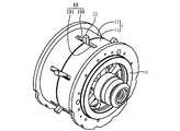
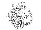
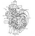
図1乃至図10を参照すると、図に示すように、本発明は、変速ケース1と複数の変速ユニット2と2つの傾斜支持ユニット3と動力入力回転体4と動力出力回転体5と、を含む無段変速機構を提供する。前記変速ケース1は、自動車のホイール状を呈すことができ、且つその両側に各々円柱状凹溝を備える。該変速ケース1は、複数の収容孔12と複数の十字形ガイド溝13と複数のガイド溝14とを備え、それら収容孔12、それら十字形ガイド溝13及びそれらガイド溝14が各々円環状に配列され、それらガイド溝14、それら収容孔12及びそれら十字形ガイド溝13が該変速ケース1の半径方向に沿って内方から外方に向かって配列され、各該収容孔12が各該十字形ガイド溝13と各該ガイド溝14の間を連通し、且つ各々円形を呈することができ;それら変速ユニット2は、変速球体21と変速ロッド22と変速スライダー23とを備え、各該変速ロッド22が各該変速球体21を遊貫し、各該変速スライダー23が各該変速ロッド22の各該変速球体21から露出する一端部に直結し、各該変速球体21が各該収容孔12に移動自在に収容され、且つ各該収容孔12の両開放側に露出し、各該変速スライダー23及び各該変速ロッド22の各該変速球体21から露出する一端部が各々各該十字形ガイド溝13の横方向部分及び縦方向部分を摺動し、且つ各該変速ロッド22の各該変速球体21から露出する一端部も該変速ケース1に露出し、各該変速ロッド22の各該変速球体21から露出する他端部が各該ガイド溝14を摺動し;それら傾斜支持ユニット3は、各々傾斜支持環体31と円錐台形ボール環体32と傾斜支持体33とを備え、各該傾斜支持環体31の両側面が各々外方傾斜支持環面311と内方傾斜挟持環面312とを有し、各該傾斜支持体33が外方傾斜挟持環面331を有し、それら傾斜支持体33が各々該変速ケース1の両側面の円柱状凹溝内に連接し、各該円錐台形ボール環体32が複数ボール321と円錐台形環体322とを備え、それらボール321が間隔を空けて該円錐台形環体322に移動自在に収容され、各該円錐台形ボール環体32が各該内方傾斜挟持環面312と各該外方傾斜挟持環面331の間を挟持し、それら外方傾斜支持環面311がそれら収容孔12の両開放側からそれら変速球体21の内周縁を支持し;該動力入力回転体4は、内方傾斜の動力入力挟持環面41を有し;該動力出力回転体5は、内方傾斜の動力出力挟持環面51を有し、該内方傾斜の動力入力挟持環面41及び該内方傾斜の動力出力挟持環面51が各々それら収容孔12の両開放側からそれら変速球体21の外周縁を挟持する。 Referring to FIGS. 1 to 10, as shown in the drawings, the present invention includes a
図10を参照すると、図に示すように、該動力入力回転体4が回転し且つそれら変速スライダー23が右に向けて摺動した時、それら変速ロッド22及びそれら変速球体21が右側に偏向し且つ各該変速ロッド22が各該変速球体21に対して摺動し、該動力出力回転体5は該動力入力回転体4の回転方向と逆回転し、且つ速度を下げる効果を奏するため、該動力出力回転体5の回転速度が該動力入力回転体4の回転速度より小さくなり;該動力入力回転体4が回転し且つそれら変速スライダー23が左に向けて摺動した時、それら変速ロッド22及びそれら変速球体21が左側に偏向し且つ各該変速ロッド22が各該変速球体21に対して摺動し、該動力出力回転体5が該動力入力回転体4の回転方向と逆回転し、且つ速度を上げる効果を奏するため、該動力出力回転体5の回転速度が該動力入力回転体4の回転速度より大きくなる。 Referring to FIG. 10, when the
図10を参照すると、図に示すように、それら変速球体21は、該内方傾斜の動力入力挟持環面41、該内方傾斜の動力出力挟持環面51及びそれら外方傾斜支持環面311の間を移動自在に挟持するため、各該変速球体21が僅か4点のみ挟持し、摩擦力が小さく、伝動効率も高く、且つ変速時にジャダーが発生しない。このほかに、該変速ケース1、それら変速ユニット2及びそれら傾斜支持ユニット3は、該動力入力回転体4の内方傾斜の動力入力挟持環面41及び該動力出力回転体5の内方傾斜の動力出力挟持環面51の挟持を介して該動力入力回転体4と該動力出力回転体5の間を浮動でき、よって該動力入力回転体4が回転を開始した時、或いは該動力入力回転体4が回転し且つそれら変速ユニット2が偏向した時、各構成要素はやはり良好な接触を保つことで伝動効率を高めさせることができ;次に、本発明の無段変速機構のそれら変速ユニット2の偏向可能な幅が大きいため、機構体積が小さく且つ幅広い無段変速範囲を有することができる。 Referring to FIG. 10, as shown in the figure, these
図1乃至図10を参照すると、図に示すように、前記無段変速機構において、該変速ケース1は、互いに連接する2つの半変速ケース11を備えることができ、それら半変速ケース11が各々複数の半収容孔121と複数の半十字形ガイド溝131と複数の半ガイド溝141とを備え、それを連結すると、それら収容孔12、それら十字形ガイド溝13及びそれらガイド溝14を形成できる。これを介して、本発明の無段変速機構の組み立てに便利で、且つ各該変速球体21は各該変速スライダー23及び各該変速ロッド22を介して各該収容孔12内に浮動するように枢着できる。 Referring to FIGS. 1 to 10, as shown in the figure, in the continuously variable transmission mechanism, the
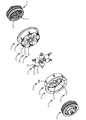
図9及び図10を参照すると、図に示すように、前記無段変速機構において、各該変速球体21内には2つのリミット潤滑嵌め輪211と潤滑嵌め輪212とを備えることができ、各該リミット潤滑嵌め輪211が自己潤滑性の嵌め輪とすることができ、各該潤滑嵌め輪212が自己潤滑性の嵌め輪とすることができ、各該変速ロッド22がそれらリミット潤滑嵌め輪211及び該潤滑嵌め輪212を遊貫でき、且つそれらリミット潤滑嵌め輪211及び該潤滑嵌め輪212を通じて各該変速球体21に対して摺動すると共に摩擦力を減らすことができる。 Referring to FIGS. 9 and 10, as shown in the figure, in the continuously variable transmission mechanism, each of the
図5乃至図8を参照すると、図に示すように、前記無段変速機構において、各該傾斜支持体33はT字形を呈することができ、各該傾斜支持体33の凸起部332が各該円錐台形ボール環体32及び各該傾斜支持環体31を挿通した後に該変速ケース1の一側面の円柱状凹溝内に連接できる。これを介して、本発明の無段変速機構は、それら変速球体21の該変速ケース1への組み込みに便利である。 Referring to FIGS. 5 to 8, as shown in the figure, in the continuously variable transmission mechanism, each of the
図5乃至図8を参照すると、図に示すように、前記無段変速機構において、各該傾斜支持体33の凸起部332は、それらガイド溝14を各々連通するため、円環状に配列された複数の延伸ガイド溝3321を備えることができる。これを介して、本発明の無段変速機構は、それら変速ユニット2の偏向範囲を広くことができる。 Referring to FIGS. 5 to 8, as shown in the figure, in the continuously variable transmission mechanism, the protruding
図6、図7、図9及び図10を参照すると、図に示すように、前記無段変速機構において、該動力入力回転体4は、第1軸部42を備えることができ、該動力出力回転体5が第2軸部52を備えることができ、該第1軸部42及び該第2軸部52が各々軸受333を通じてそれら傾斜支持体33を枢着できる。これを介して、本発明の無段変速機構は、更に該変速ケース1、それら変速ユニット2及びそれら傾斜支持ユニット3を該動力入力回転体4と該動力出力回転体5の間に安定して連接させることができる。 Referring to FIGS. 6, 7, 9, and 10, in the continuously variable transmission mechanism, as shown in the figure, the power
図1、図10及び図11を参照すると、図に示すように、前記無段変速機構において、円環状の駆動体6を更に含むことができ、該円環状の駆動体6は複数の斜めガイド孔61を備え、該円環状の駆動体6が該変速ケース1上に嵌め込まれることができ、それら斜めガイド孔61がそれら変速ロッド22の該変速ケース1に露出する一端部を各々ガイドできる。これを介して、該円環状の駆動体6が該変速ケース1に対して時計回り方向に回転或いは反時計回り方向に回転した時、それら変速ロッド22は各々それら斜めガイド孔61にガイドされてそれら変速ロッド22及びそれら変速球体21を左側に偏向又は右側に偏向させることができる。 1, 10, and 11, as shown in the figure, the continuously variable transmission mechanism may further include an annular driving body 6, and the annular driving body 6 includes a plurality of oblique guides. The annular driving body 6 can be fitted onto the
発明の詳細な説明の項においてなされた好ましい実施例は、あくまでも本発明の技術内容を明らかにするものであって、そのような具体例にのみ限定して狭義に解釈されるべきものではないことは当業者にとって明白だろう。ここで留意すべき点は、当該実施例との等価構造変化及び置換は、いずれも本発明の範疇内にカバーする。よって本発明の保護範囲は、特許請求の範囲で特定するものに準じる。 The preferred embodiments made in the section of the detailed description of the invention are merely to clarify the technical contents of the present invention, and should not be construed in a narrow sense by limiting only to such specific examples. Will be apparent to those skilled in the art. It should be noted that all equivalent structural changes and substitutions with the embodiment are within the scope of the present invention. Therefore, the protection scope of the present invention conforms to that specified in the claims.
1 変速ケース
11 半変速ケース
12 収容孔
121 半収容孔
13 十字形ガイド溝
131 半十字形ガイド溝
14 ガイド溝
141 半ガイド溝
2 変速ユニット
21 変速球体
211 リミット潤滑嵌め輪
212 潤滑嵌め輪
22 変速ロッド
23 変速スライダー
3 傾斜支持ユニット
31 傾斜支持環体
311 外方傾斜支持環面
312 内方傾斜挟持環面
32 円錐台形ボール環体
321 ボール
322 円錐台形環体
33 傾斜支持体
331 外方傾斜挟持環面
332 凸起部
3321 延伸ガイド溝
333 軸受
4 動力入力回転体
41 内方傾斜の動力入力挟持環面
42 第1軸部
5 動力出力回転体
51 内方傾斜の動力出力挟持環面
52 第2軸部
6 円環状の駆動体
61 斜めガイド孔DESCRIPTION OF
Claims (3)
Translated fromJapanese各々変速球体と変速ロッドと変速スライダーとを備え、各前記変速ロッドが各前記変速球体に遊貫させ、各前記変速スライダーが各前記変速ロッドの各前記変速球体から露出する一端部に直結し、各前記変速球体が各前記収容孔に移動自在に収容され、且つ各前記収容孔の両開放側に露出し、各前記変速スライダー及び各前記変速ロッドの各前記変速球体から露出する一端部が各前記十字形ガイド溝を摺動し、各前記変速ロッドの各前記変速球体から露出する他端部が各前記ガイド溝を摺動する複数の変速ユニットと、
傾斜支持環体と円錐台形ボール環体と傾斜支持体とを各々備え、各前記傾斜支持環体は外方傾斜支持環面と内方傾斜挟持環面とを有し、各前記傾斜支持体が外方傾斜挟持環面を有し、前記傾斜支持体が前記変速ケースの両側面に各々連接し、各前記円錐台形ボール環体が各前記内方傾斜挟持環面と各前記外方傾斜挟持環面の間を挟持し、前記外方傾斜支持環面が各々前記収容孔の両開放側から前記変速球体を支持する2つの傾斜支持ユニットと、
内方傾斜の動力入力挟持環面を有する動力入力回転体と、
内方傾斜の動力出力挟持環面を有し、前記内方傾斜の動力入力挟持環面及び前記内方傾斜の動力出力挟持環面が各々前記収容孔の両開放側から前記変速球体を挟持する動力出力回転体と、
を含むことを特徴とする無段変速機構。A plurality of receiving holes, a plurality of cross-shaped guide grooves, and a plurality of guide grooves, wherein the receiving holes, the cross-shaped guide grooves and the guide grooves are each arranged in an annular shape; A speed change case in which cross-shaped guide grooves are arranged from the inside toward the outside, and each of the receiving holes communicates between each of the cross-shaped guide grooves and each of the guide grooves,
Each of the speed change spheres, speed change rods, and speed change sliders, the speed change rods loosely penetrate the speed change spheres, and the speed change sliders are directly connected to the end portions of the speed change rods exposed from the speed change spheres, Each of the speed change spheres is movably accommodated in each of the accommodation holes, and is exposed to both open sides of each of the accommodation holes, and one end portion of each speed change slider and each speed change rod that is exposed from each speed change sphere is A plurality of speed change units that slide in the cross-shaped guide grooves, and the other end portions exposed from the speed change spheres of the speed change rods slide in the guide grooves;
An inclined support ring, a frustoconical ball ring, and an inclined support, each inclined support ring having an outer inclined support ring surface and an inward inclined clamping ring surface, and each of the inclined support members Each of the frustoconical ball rings is connected to each of the inner inclined clamping ring and each of the outer inclined clamping rings. Two inclined support units sandwiching between the surfaces, and each of the outer inclined support ring surfaces supports the transmission sphere from both open sides of the accommodation hole,
A power input rotator having an inwardly inclined power input clamping ring;
An inwardly inclined power output holding ring surface, and the inwardly inclined power input holding ring surface and the inwardly inclined power output holding ring surface hold the shift sphere from both open sides of the accommodation hole, respectively. A power output rotor,
A continuously variable transmission mechanism comprising:
Priority Applications (1)
| Application Number | Priority Date | Filing Date | Title |
|---|---|---|---|
| JP2017032790AJP6429339B2 (en) | 2017-02-24 | 2017-02-24 | Continuously variable transmission mechanism |
Applications Claiming Priority (1)
| Application Number | Priority Date | Filing Date | Title |
|---|---|---|---|
| JP2017032790AJP6429339B2 (en) | 2017-02-24 | 2017-02-24 | Continuously variable transmission mechanism |
Publications (2)
| Publication Number | Publication Date |
|---|---|
| JP2018136011A JP2018136011A (en) | 2018-08-30 |
| JP6429339B2true JP6429339B2 (en) | 2018-11-28 |
Family
ID=63365440
Family Applications (1)
| Application Number | Title | Priority Date | Filing Date |
|---|---|---|---|
| JP2017032790AExpired - Fee RelatedJP6429339B2 (en) | 2017-02-24 | 2017-02-24 | Continuously variable transmission mechanism |
Country Status (1)
| Country | Link |
|---|---|
| JP (1) | JP6429339B2 (en) |
Family Cites Families (4)
| Publication number | Priority date | Publication date | Assignee | Title |
|---|---|---|---|---|
| US7011600B2 (en)* | 2003-02-28 | 2006-03-14 | Fallbrook Technologies Inc. | Continuously variable transmission |
| EP2142826B1 (en)* | 2007-04-24 | 2015-10-28 | Fallbrook Intellectual Property Company LLC | Electric traction drives |
| US8784261B2 (en)* | 2009-12-02 | 2014-07-22 | Toyota Jidosha Kabushiki Kaisha | Continuously variable transmission |
| JP6033388B1 (en)* | 2015-10-22 | 2016-11-30 | 摩特動力工業股▲ふん▼有限公司Motive Power Industry Co.,Ltd. | Linear transmission mechanism for chainless vehicles |
- 2017
- 2017-02-24JPJP2017032790Apatent/JP6429339B2/ennot_activeExpired - Fee Related
Also Published As
| Publication number | Publication date |
|---|---|
| JP2018136011A (en) | 2018-08-30 |
Similar Documents
| Publication | Publication Date | Title |
|---|---|---|
| JP2013053734A (en) | Cage for rolling bearing and rolling bearing | |
| JP6429339B2 (en) | Continuously variable transmission mechanism | |
| TW201907101A (en) | Continuously variable transmission control system for rolling vehicle | |
| US8092335B2 (en) | Differential for vehicle | |
| TWI648494B (en) | Stepless speed change mechanism | |
| TWI571576B (en) | Linear gear transmission mechanism | |
| JP2015158212A (en) | thrust bearing | |
| CA2936457C (en) | Linear gear shift mechanism | |
| EP3327305A1 (en) | Transmission | |
| CN113631820B (en) | Inner ring separated angular contact ball bearing | |
| TWI610038B (en) | Stepless shifting ring seat drive mechanism | |
| US20170122368A1 (en) | Tapered Roller Bearing | |
| JP6154873B2 (en) | Linear transmission mechanism | |
| JP5348271B2 (en) | Ball bearing | |
| CN203670511U (en) | Novel oil ring adopting oil carrying structure | |
| JP5909918B2 (en) | Roller bearing cage | |
| JP2013092240A (en) | Cage for deep groove ball bearing, deep groove ball bearing using the cage, and bearing device | |
| JP6374552B1 (en) | Drive mechanism for continuously variable annular base | |
| JP2018091399A (en) | Holder for rolling bearing, and rolling bearing including the same | |
| KR20210054100A (en) | Ball spline having oil filling structure | |
| JP2019027468A (en) | Continuously variable speed control system of rolling vehicle | |
| CN106555871B (en) | Linear gear mechanism | |
| US20170102052A1 (en) | Linear gear shift mechanism | |
| JP2017223363A (en) | Weight device | |
| KR101747547B1 (en) | Linear gear shift mechanism |
Legal Events
| Date | Code | Title | Description |
|---|---|---|---|
| A521 | Request for written amendment filed | Free format text:JAPANESE INTERMEDIATE CODE: A523 Effective date:20180529 | |
| TRDD | Decision of grant or rejection written | ||
| A01 | Written decision to grant a patent or to grant a registration (utility model) | Free format text:JAPANESE INTERMEDIATE CODE: A01 Effective date:20181016 | |
| A61 | First payment of annual fees (during grant procedure) | Free format text:JAPANESE INTERMEDIATE CODE: A61 Effective date:20181026 | |
| R150 | Certificate of patent or registration of utility model | Ref document number:6429339 Country of ref document:JP Free format text:JAPANESE INTERMEDIATE CODE: R150 | |
| LAPS | Cancellation because of no payment of annual fees |