JP6428411B2 - Drawing apparatus and nail inclination detection method - Google Patents
Drawing apparatus and nail inclination detection methodDownload PDFInfo
- Publication number
- JP6428411B2 JP6428411B2JP2015054435AJP2015054435AJP6428411B2JP 6428411 B2JP6428411 B2JP 6428411B2JP 2015054435 AJP2015054435 AJP 2015054435AJP 2015054435 AJP2015054435 AJP 2015054435AJP 6428411 B2JP6428411 B2JP 6428411B2
- Authority
- JP
- Japan
- Prior art keywords
- nail
- finger
- inclination
- unit
- width direction
- Prior art date
- Legal status (The legal status is an assumption and is not a legal conclusion. Google has not performed a legal analysis and makes no representation as to the accuracy of the status listed.)
- Active
Links
Images


Classifications
- G—PHYSICS
- G06—COMPUTING OR CALCULATING; COUNTING
- G06T—IMAGE DATA PROCESSING OR GENERATION, IN GENERAL
- G06T7/00—Image analysis
- G06T7/70—Determining position or orientation of objects or cameras
- G06T7/73—Determining position or orientation of objects or cameras using feature-based methods
- A—HUMAN NECESSITIES
- A45—HAND OR TRAVELLING ARTICLES
- A45D—HAIRDRESSING OR SHAVING EQUIPMENT; EQUIPMENT FOR COSMETICS OR COSMETIC TREATMENTS, e.g. FOR MANICURING OR PEDICURING
- A45D29/00—Manicuring or pedicuring implements
- A—HUMAN NECESSITIES
- A45—HAND OR TRAVELLING ARTICLES
- A45D—HAIRDRESSING OR SHAVING EQUIPMENT; EQUIPMENT FOR COSMETICS OR COSMETIC TREATMENTS, e.g. FOR MANICURING OR PEDICURING
- A45D29/00—Manicuring or pedicuring implements
- A45D2029/005—Printing or stamping devices for applying images or ornaments to nails
Landscapes
- Engineering & Computer Science (AREA)
- Computer Vision & Pattern Recognition (AREA)
- Physics & Mathematics (AREA)
- General Physics & Mathematics (AREA)
- Theoretical Computer Science (AREA)
- Coating Apparatus (AREA)
- Manufacturing & Machinery (AREA)
Description
Translated fromJapanese本発明は、描画装置及び描画装置を用いた爪傾き検出方法に関するものである。 The present invention relates to a drawing apparatus and a nail inclination detection method using the drawing apparatus.
従来、爪にネイルデザインを描画する描画装置が知られている(例えば、特許文献1参照)。
このような装置を用いれば、ネイルサロン等を利用しなくても手軽にネイルデザインを楽しむことができる。2. Description of the Related Art Conventionally, a drawing apparatus that draws a nail design on a nail is known (see, for example, Patent Document 1).
If such an apparatus is used, a nail design can be easily enjoyed without using a nail salon or the like.
しかしながら、ネイルプリント用の描画装置の描画対象である爪は、通常の描画装置の描画対象である紙等と異なり、その爪を有する指がその延在方向の軸を回転中心として回転することで、爪が傾いてしまうことがある。
爪が傾いてしまった場合に、これに気付かずに傾いた状態のまま描画してしまうと、描画されたデザインが傾いたり歪んだりしてしまい、美しい仕上がりとならない。
このため、爪が傾いている場合には、傾いた分を補正した上で描画したり、描画動作を中止して指をセットし直したりすようにユーザに促す等の対応をすることが好ましい。However, the nail that is the drawing target of the drawing device for nail printing is different from the paper that is the drawing target of the normal drawing device, and the finger having the nail rotates around the axis in the extending direction. , The nails may tilt.
If the nail is tilted and it is drawn without being aware of it, the drawn design will be tilted or distorted, resulting in a beautiful finish.
For this reason, when the nail is inclined, it is preferable to correct the amount of inclination and draw, or to prompt the user to stop the drawing operation and reset the finger. .
しかし、爪を上方から撮影して得た画像から爪の輪郭(爪領域)を検出する従来の構成では、指が回転していることによる爪の傾きを精度よく検出することは困難であった。 However, with the conventional configuration in which the nail contour (nail region) is detected from an image obtained by photographing the nail from above, it is difficult to accurately detect the nail inclination due to the rotation of the finger. .
本発明の課題は、比較的簡易な構成で、精度よく爪の傾きを検出することができる描画装置及び描画装置を用いた爪傾き検出方法を提供することである。 An object of the present invention is to provide a drawing apparatus and a nail inclination detection method using the drawing apparatus that can accurately detect the inclination of the nail with a relatively simple configuration.
前記課題を解決するために、本発明の描画装置は、
爪を有する指が載置される載置面を有する載置部と、
前記爪の幅方向に沿って、前記爪の上に撮影可能に形成された撮影対象物を撮影した画像における、前記撮影対象物の前記幅方向に沿った形状に基づいて、前記爪の前記載置面に対する傾斜状態を検出する爪傾き検出部と、
を備えていることを特徴としている。In order to solve the above problems, a drawing apparatus of the present invention provides:
A placement portion having a placement surface on which a finger having a nail is placed;
The description above of the nail based on the shape along the width direction of the photographing object in an image obtained by photographing the photographing object formed on the nail so as to be photographable along the width direction of the nail. A claw inclination detecting unit for detecting an inclination state with respect to the placement surface;
It is characterized by having.
本発明によれば、比較的簡易な構成で、精度よく爪の傾きを検出することができる。 According to the present invention, it is possible to accurately detect the inclination of the nail with a relatively simple configuration.
以下、添付図面を参照して、本発明に係る描画装置及び描画装置を用いた爪傾き検出方法の実施形態の一例を詳細に説明する。ただし、発明の範囲は、図示例に限定されない。
また、以下の実施形態では、描画装置は手の指の爪を描画対象として、これに描画するものとして説明するが、本発明の描画対象は手の指の爪に限るものではなく、例えば足の指の爪を描画対象としてもよい。Hereinafter, an example of an embodiment of a drawing apparatus and a nail inclination detection method using the drawing apparatus according to the present invention will be described in detail with reference to the accompanying drawings. However, the scope of the invention is not limited to the illustrated examples.
In the following embodiments, the drawing apparatus will be described assuming that the fingernail of the hand is drawn on the drawing object, but the drawing object of the present invention is not limited to the fingernail of the hand. The fingernail may be drawn.
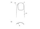
図1は、描画装置の正面図であり、図2は図1に示す描画装置の一部を断面にして内部構造を示した側面図である。
図1及び図2に示すように、この描画装置1は、描画ヘッド41とペン等の筆記具71とを備えるハイブリッド方式のネイルプリント装置であり、ケース本体2と、このケース本体2に収容される装置本体10と、を備えている。なお、図1及び図2において、ケース本体を二点鎖線で示している。FIG. 1 is a front view of the drawing apparatus, and FIG. 2 is a side view showing the internal structure of a part of the drawing apparatus shown in FIG.
As shown in FIGS. 1 and 2, the
ケース本体2の前面上部の一端には、後述する描画部40の筆記具71を交換するために開閉可能に構成された筆記具交換用蓋部23が設けられている。筆記具交換用蓋部23は、例えばヒンジ等を介して、図2に示すように閉状態から開状態まで回動自在となっている。
さらに、ケース本体2の一側面(本実施形態では、図1において左側面)であって後述する筆記具慣書部61に対応する位置には、筆記具慣書部61に載置される被描画媒体(図示せず)を入れ替え可能な媒体挿出口24が形成されている。One end of the front upper portion of the
Further, a drawing medium placed on the writing instrument custom-designing
ケース本体2の上面(天板)には操作部25(図5参照)が設置されている。
操作部25は、ユーザが各種入力を行う入力部である。
操作部25には、例えば、描画装置1の電源をONする電源スイッチ釦、動作を停止させる停止スイッチ釦、爪Tに描画するデザイン画像を選択するデザイン選択釦、描画開始を指示する描画開始釦等、各種の入力を行うための図示しない操作釦が配置されている。An operation unit 25 (see FIG. 5) is installed on the upper surface (top plate) of the
The
The
また、ケース本体2の上面(天板)のほぼ中央部には表示部26が設置されている。
表示部26は、例えば液晶ディスプレイ(LCD:Liquid Crystal Display)、有機エレクトロルミネッセンスディスプレイその他のフラットディスプレイ等で構成されている。
本実施形態において、この表示部26には、例えば、印刷指U1を撮影して得た指画像(爪Tの画像を含む印刷指U1の画像)、この指画像中に含まれる爪Tの輪郭線等の画像、爪Tに描画すべきデザイン画像を選択するためのデザイン選択画面、デザイン確認用のサムネイル画像、各種の指示を表示させる指示画面等が適宜表示される。
特に本実施形態では、後述する爪傾き検出部812b(図5参照)が検出した爪Tの傾きが所定以上である場合には、指をセットし直すように促す等のメッセージを表示部26の表示画面に表示させるようになっており、表示部26は、爪Tの傾きが所定以上の場合にユーザに報知する報知部として機能する。
なお、表示部26の表面にタッチパネルが一体的に構成されていてもよい。この場合には、例えば、指先等でタッチパネル表面にタッチすることにより各種選択や指示を行うことができる。指以外でも例えばスタイラスペンや、先の尖った棒状の筆記具等によって表示部26の表面をタッチするタッチ操作によっても各種の入力を行うことができるように構成される。In addition, a
The
In the present embodiment, the
In particular, in the present embodiment, when the inclination of the nail T detected by a nail
A touch panel may be integrally formed on the surface of the
装置本体10は、ほぼ箱状に形成され、ケース本体2の内部下方に設置された下部機枠11と、この下部機枠11の上方で且つケース本体2の内部上方に設置されている上部機枠12と、を備えている。 The apparatus
まず、下部機枠11について説明する。
下部機枠11は、背面板111、底板112、左右一対の側板113a,113b、X方向移動ステージ収容部114、Y方向移動ステージ収容部115及び隔壁116を有する。
側板113a,113bの下端部は、底板112の左右両端部にそれぞれ連結され、側板113a,113bが底板112に対して立てられた状態に設けられている。
図2に示すように、背面板111の下部は、前方(指挿入方向手前側)に向かって2段に窪むように形成されている。背面板111の下端部は底板112の前端部に連結されており、背面板111は、底板112と側板113a,113bによって囲われた領域を前後に区切っている。
この窪んだ背面板111の後ろ側に形成される空間がX方向移動ステージ収容部114、Y方向移動ステージ収容部115(図2参照)となっている。X方向移動ステージ収容部114内には、描画部40(図2参照)が前方(指挿入方向手前側)に移動した際に描画部40のX方向移動ステージ45が収容される。また、Y方向移動ステージ収容部115内には、描画部40のY方向移動ステージ47が配置されている。
また、隔壁116は、下部機枠11の内部前方側の空間(背面板111、底板112及び側板113a,113bによって囲われた指挿入方向手前側の空間)を上下に区切るように下部機枠11の内側に設けられている。隔壁116はほぼ水平に設けられ、隔壁116の左右両端部が側板113a,113bにそれぞれ連結され、隔壁116の後端部が背面板111に連結されている。First, the
The
The lower ends of the
As shown in FIG. 2, the lower portion of the
The space formed on the back side of the recessed back
Further, the
この下部機枠11には、指固定部30が一体的に設けられている。
図3を参照して、指固定部30について説明する。
図3は指固定部30及びその周辺の構成を模式的に示した要部断面図である。The
The
FIG. 3 is a cross-sectional view of an essential part schematically showing the configuration of the
指固定部30は、描画対象である、描画を施す爪Tに対応する指(以下、これを「印刷指U1」という。)を受け入れる指受入部31と、描画対象でない、この印刷指U1以外の指(以下、これを「非印刷指U2」という。)を退避させる指退避部32と、から構成されている。
指受入部31は、隔壁116の上側であって下部機枠11の幅方向のほぼ中央部に配置されている。また、隔壁116によって下部機枠11の下側に区分けられた空間が指退避部32を構成している。
例えば、薬指の爪Tに描画を施す場合には、図3に示すように、指受入部31に印刷指U1としての薬指を挿入し、非印刷指U2であるその他の4指(親指、人差し指、中指、小指)を指退避部32に挿入する。
指受入部31は、下部機枠11の前面側(印刷指挿入方向の手前側)に開口しており、下側が隔壁116の一部を構成する指載置部116a、両側が仕切り31a、奥側が仕切り31cによって区画されている。指載置部116aは、載置面(XY平面)を有し、描画を施す爪Tの指(印刷指U1)を載置面上に載置するものである。
また、指受入部31の上側は天井部31dによって区画されている。天井部31dには、指受入部31に挿入された印刷指U1の爪Tを露出させるための窓31eが形成されている。The
The
For example, when drawing on the nail T of the ring finger, as shown in FIG. 3, the ring finger as the printing finger U1 is inserted into the
The
Further, the upper side of the
指載置部116aの載置面上には、指受入部31内に挿入された印刷指U1を下側から保持する指保持部33が配置されている。指保持部33は、図示しない機構により昇降可能に構成されていてもよい。この場合には、印刷指U1を指受入部31内に挿入したり、指受入部31内から取り出したりする際には、指保持部33が印刷指U1の出し入れの支障とならない高さまで下降し、印刷指U1を固定する際には、印刷指U1の上面が天井部31dの下面に突き当たる位置まで印刷指U1を押し上げるように指保持部33が上昇するようにする。
また、指受入部31内には、仕切り31cから突出する爪乗せ台34が設けられており、印刷指U1が指保持部33によって押し上げられた状態において、爪Tの先端部分が爪乗せ台34の上に乗るようになっている。これにより、爪Tの高さ方向における位置が固定される。
なお、指保持部33、爪乗せ台34は描画装置の必須の構成ではなく、これを備えない装置でもよい。On the placement surface of the
Further, a
Note that the
また、隔壁116の上面であって下部機枠11の前面側の両側部には、下部機枠11の前面側を塞ぐ前壁31f(図1参照)が立設されている。また、隔壁116の上面には、この前壁31fの中央部寄りの端部から前記指受入部31に向けて狭窄し、印刷指U1を指受入部31内に案内する一対のガイド壁31gが立設されている。
ユーザは指受入部31に挿入した印刷指U1と指退避部32に挿入した非印刷指U2との間に隔壁116を挟むことができる。そのため、指受入部31内に挿入された印刷指U1が安定して固定される。
なお、本実施形態では、隔壁116の前端部に下方向に張り出した突出部116bが形成されている。突出部116bは、手前側に向かうにつれてその厚さが漸減し、奥側に向かうにつれて漸増するテーパー部となっていてもよいし、突出部116bの厚さが、隔壁116の奥側の窪みに対して全体が厚い構造になっていてもよい。隔壁116の前端部に突出部116bが形成されていることにより、非印刷指U2が指退避部32に挿入された際、描画済みの指の爪Tと隔壁116との間に空間が確保され、爪Tが隔壁116の下面に接触して装置側にインクが付着したり、爪Tに描画された絵柄が擦れて損なわれたりするのを防止することができる。Further,
The user can sandwich the
In the present embodiment, a protruding
隔壁116の上面であって、指受入部31の横(ケース本体2の媒体挿出口24に対応する位置であり、本実施形態では、図1において左側)の領域は、非描画時に、描画ヘッド41及び筆記具71が待機しているホームエリアとなっている。
このホームエリアには、筆記具慣書部61、筆記具キャップ62及びヘッドキャップ機構43が設けられている。An area on the upper surface of the
This home area is provided with a writing instrument
筆記具慣書部61は、後述する筆記具71の慣らし書きをするためのものであり、筆記具71による描画可能範囲内に配置されている。
筆記具慣書部61は、平板状の部分であり、前述のケース本体2の媒体挿出口24から挿入された図示しない被描画媒体が載置されるようになっている。
筆記具慣書部61に載置される被描画媒体は、ペン先712を慣らすことができるものであればよく、例えば紙片である。
なお、筆記具慣書部61は、印刷指U1が指受入部31に挿入された際の爪Tの高さとほぼ同じとなる高さに設けられていることが好ましい。The writing
The writing instrument
The drawing medium placed on the writing
Note that the writing instrument
筆記具慣書部61は、ペン先712が乾いていたりインクの乗りが悪い等により書き始めがかすれたりするのを防止するために、爪Tに画像データによる描画を開始する前に被描画媒体の上に筆記具71を下ろして「○」や「∞」等の所定の図形を描画して慣らし書きを行い、ペン先712の状態を良好にするためのものである。慣らし書きを行う際に描画する所定の図形は特に限定されないが、インクを無駄に使いすぎないよう、「○」や「∞」等の単純な図形であることが好ましい。この慣らし書きにおいては、筆記具慣書部61の範囲内で、慣らし書きを行う度に「○」や「∞」等の図形を描画する位置を少しずつずらしながら書くようにすることが好ましい。なお、被描画媒体のほぼ全面に書いてしまったときには、表示部26に「紙を交換して下さい」等の被描画媒体の交換を促す表示画面を表示させるようにする。この場合、ユーザが媒体挿出口24から被描画媒体を取り出して新しいものと交換することにより新しい被描画媒体に慣らし書きができる状態となる。もし、被描画媒体がロール紙である場合は、描画スペースが無くなったときには、ロール紙から被描画媒体を繰り出し、新しい描画面に慣らし書きを行えるようにする。 The writing
筆記具キャップ62は、描画部40に筆記具71を装着後であって描画を行っていないとき(非描画時)に、筆記具71(特に筆記具71のペン先712)が収容されるものであり、例えばゴム等で形成されている。
本実施形態では、筆記具キャップ62が筆記具慣書部61の前方(指挿入方向の手前側)に設置されている。筆記具キャップ62は、描画部40に装着される筆記具71に対応する数(本実施形態では4つ)だけ設けられている。
非描画時には、筆記具71を筆記具キャップ62の真上に筆記具71を移動させた後、後述するソレノイド742によって筆記具71を下降させ、ペン先712を筆記具キャップ62内に収容する。これにより、非描画時におけるペン先712の乾燥を防止できるようになっている。なお、筆記具キャップ62の形状等は図示例に限定されず、例えば、描画部40に装着される全ての筆記具71のペン先712を受け入れることのできる長尺な溝状の筆記具キャップ等であってもよい。
なお、本実施形態では、このように、筆記具キャップ62が筆記具慣書部61の傍に設けられているので、描画を開始するときには、筆記具71を上昇させてすぐ傍の筆記具慣書部61で慣らし書きを行い、描画を開始することができる。このため、筆記具71の移動等にかかる時間を最小限に抑えることができ、迅速な描画動作を行うことができる。The
In the present embodiment, the
At the time of non-drawing, the
In the present embodiment, since the
また、ヘッドキャップ機構43は、非描画時に描画ヘッド41の吐出面を覆うものである。ヘッドキャップ機構43は、隔壁116の上であって、筆記具71が筆記具キャップ62内に収容されている際に描画ヘッド41が配置される位置に対応する位置に配置されている。
ヘッドキャップ機構43を設けて、非描画時に描画ヘッド41の吐出面を覆うことにより、非描画時における描画ヘッド41の乾燥を防ぐことができる。The
By providing the
描画部40は、複数種類のインクを用いて、選択されたデザイン画像の画像データに基づき爪Tに描画を施すものであり、本実施形態では描画用具である描画ヘッド41及び筆記具71を備える筆記具ユニット72が搭載されたキャリッジ42を備えている。
キャリッジ42は、キャリッジ支持部材44に取り付けられており、これにより、描画ヘッド41及び筆記具ユニット72は、キャリッジ42を介してキャリッジ支持部材44に支持されている。
描画部40は、キャリッジ42及びこれを支持するキャリッジ支持部材44の他、キャリッジ42をX方向(図1におけるX方向、描画装置1の左右方向)に移動させるためのX方向移動ステージ45、X方向移動モータ46、キャリッジ42をY方向(図2におけるY方向、描画装置1の前後方向)に移動させるためのY方向移動ステージ47、Y方向移動モータ48等を備えて構成されている。The
The
The
描画ヘッド41は、液状材料であるインクを描画対象面である爪Tの表面に噴射塗布して、この爪Tの表面に描画を施すインクジェット方式の描画用具である。なお、描画ヘッド41がインクを噴射塗布する構成、方式は特に限定されない。
本実施形態の描画ヘッド41は、インクタンクが一体化された一体型のカートリッジであり、内部には、個別に仕切られた複数のインク室(インク収容部、図示せず)が設けられ、各インク室内には、例えば、液状材料としてC,M,Y3色のインクがそれぞれ充填されている。なお、インク(液状材料)の種類や数はここに例示したものに限定されない。
描画ヘッド41の下側面(描画ヘッド41をキャリッジ42に装着した際に指載置部116aに対向する面)には、インク室に充填されている各色のインクを吐出させる吐出口が形成された吐出面(図示せず)が設けられている。
描画ヘッド41は、この吐出面の吐出口からインクを吐出させるためのインク吐出部411を備えている。インク吐出部411は、例えばアクチュエータとしてのピエゾ素子(図示せず)等で構成されている。
キャリッジ42には、描画ヘッド41を駆動させるヘッドドライブ回路基板(図示せず)が設けられており、キャリッジ42に描画ヘッド41を装着した際に描画ヘッド41側のコネクタ(図示せず)がヘッドドライブ回路基板と接続され、ヘッドドライブ回路基板を介してインク吐出部411が制御装置80と電気的に接続される。これにより、後述する描画制御部815の制御にしたがって、インク吐出部411を構成するピエゾ素子に駆動電圧が印加され、電圧の印加によってピエゾ素子が変形又は振動することで図示しないインク流路が圧縮されて吐出面の吐出口からインクが吐出されるようになっている。The drawing
The drawing
On the lower surface of the drawing head 41 (the surface facing the
The drawing
The
筆記具ユニット72は、印刷指U1の爪Tに描画を施す描画用具である筆記具71を少なくとも一つ備えている。筆記具71は筆記具保持部73に保持されている。
本実施形態において、筆記具ユニット72は、それぞれ1本ずつ筆記具71を保持する筆記具保持部73(後述)を4つ備えている。なお、筆記具保持部73の数・形状等は図示例に限定されない。
筆記具71は、前述の筆記具交換用蓋部23を開けて適宜交換することが可能である。なお、筆記具71は、全ての筆記具保持部73に装着されていてもよいし、4つの筆記具保持部73のうちの一部のみに装着されていてもよい。The
In the present embodiment, the
The writing
描画用具である筆記具71は、爪Tの表面に液状材料であるインクを塗布して描画を施すものである。
各筆記具保持部73に保持される筆記具(描画用具)71は、ペン軸部711の先端側にペン先712が設けられたものである。ペン軸部711の内部は、各種インクを収容するインク収容部となっている。ペン軸部711の内部に収容されるインクは、粘度や色材の粒径(粒子の大きさ)等は特に限定されず、例えば、金銀のラメ入りのインクや白色のインク、UV硬化型のインクやジェルネイル、アンダーコート用、トップコート用やマニキュア等も用いることができる。The
The writing tool (drawing tool) 71 held in each writing
筆記具71は、例えばペン先712を爪Tの表面に押し当てることでペン軸部711内に収容されているインクが染み出して描画する、ペン先712がボールペンタイプとなったペンである。なお、筆記具71は、ボールペンタイプのものに限定されず、例えばフェルト状のペン先にインクを染み込ませて描画するサインペンタイプや、束ねた毛にインクを染み込ませて描画する筆ペンタイプのもの等であってもよい。また、ペン先712の太さも各種のものを用意することができる。
各筆記具保持部73に保持される筆記具71は、同じタイプのペン先712を有するペンでもよいし、異なるタイプのペン先712を有する筆記具であってもよい。The
The
なお、本実施形態では、筆記具71を保持する筆記具保持部73が装置の幅方向(左右方向、図1におけるX方向)に4つ並んでいるため、ペン先712の位置がX方向(装置の左右方向)にずれているが、このずれは描画動作における1ステップの整数倍になっており、描画に使われる筆記具71に応じて当該ずれている分のステップ数だけ補正して描画を行うため、4つの筆記具71は、同じ位置に描画を行うことができるようになっている。 In the present embodiment, since four writing
各筆記具保持部73には、筆記具71をほぼ垂直に保持する筒状部である筆記具ホルダ731が設けられている。筆記具ホルダ731は、筆記具71をほぼ垂直に保持した状態でばね741とソレノイド742との協働によって筆記具71を上下移動させるようになっている。具体的には、ソレノイド742が駆動されている状態ではばね741の付勢力に抗して筆記具71が降下して、描画対象である爪Tの表面や被描画媒体と接触可能な描画状態となる。また、ソレノイド742が開放された状態では、ばね741の付勢力によって筆記具71が上昇し、爪Tの表面や被描画媒体と接触しない非描画状態となる。
なお、本実施形態では、筆記具71を上下させるためのアクチュエータとしてソレノイド742を用いているが、筆記具71を上下させるためのアクチュエータは、ソレノイド742に限定されない。筆記具71は軽量であるため、ソレノイドの他、各種小型の駆動装置により筆記具71を上下させるためのアクチュエータを構成することができる。Each writing
In this embodiment, the
キャリッジ42を支持するキャリッジ支持部材44は、X方向移動ステージ45に取り付けられたX方向移動部451に固定されている。X方向移動部451は、X方向移動モータ46の駆動によりX方向移動ステージ45上を図示しないガイドに沿ってX方向に移動するようになっており、これにより、キャリッジ42がX方向(図1におけるX方向、描画装置1の左右方向)に移動するようになっている。
また、X方向移動ステージ45は、Y方向移動ステージ47のY方向移動部471に固定されている。Y方向移動部471は、Y方向移動モータ48の駆動によりY方向移動ステージ47上を図示しないガイドに沿ってY方向に移動するようになっており、これにより、キャリッジ42がY方向(図2におけるY方向、描画装置1の前後方向)に移動するようになっている。
なお、本実施形態において、X方向移動ステージ45及びY方向移動ステージ47は、X方向移動モータ46、Y方向移動モータ48と、図示しないボールネジ及びガイドとを組み合わせることで構成されている。本実施形態のX方向移動モータ46及びY方向移動モータ48としては、1パルス送られるごとに所定量ずつ移動するステップモータが適用される。
本実施形態では、X方向移動モータ46及びY方向移動モータ48等により、爪Tに描画を施す筆記具71を備えるキャリッジ42をX方向及びY方向に駆動するキャリッジ移動部49(図5参照)が構成されている。A
The X
In this embodiment, the X
In the present embodiment, the carriage moving unit 49 (see FIG. 5) that drives the
描画部40における描画ヘッド41のインク吐出部411、筆記具71を上下移動させるためのソレノイド742、X方向移動モータ46、Y方向移動モータ48は、後述する制御装置80の描画制御部815(図5参照)に接続され、該描画制御部815によって制御されるようになっている。 The
図1及び図2に示すように、上部機枠12には基板13が設置されている。
この基板13の裏面側(すなわち、図1及び図2において下側)には、装置の前後方向(図2におけるY方向)に延在してガイドレール57が設けられている。
また、このガイドレール57には移動ステージ56が取り付けられている。移動ステージ56は、ステージ移動用モータ58(図5参照)によって、ガイドレール57に沿って装置の前後方向(図2におけるY方向)に移動可能に構成されている。As shown in FIGS. 1 and 2, a
On the back side of the substrate 13 (that is, the lower side in FIGS. 1 and 2), a
A moving
この移動ステージ56における左右方向(すなわち図1におけるX方向)の中央部であって、前後方向(すなわち図2におけるY方向)における装置奥側(すなわち図2における左側)の下面には、レーザ照射部55が設置されている。
本実施形態において、レーザ照射部55は、レーザ光を照射する図示しないレーザ光源と、このレーザ光源からの光を1直線状(ライン状)の光にするための図示しないスリット部とを有している。レーザ照射部55は、レーザ光源からの光を、スリット部を介して照射することにより、ライン状のレーザ光(以下においてラインレーザ光とする。)を対象物に照射するものであり、本実施形態では、後述する爪領域検出部812aによって検出された爪領域の幅方向にライン(撮影対象物)La(図6(a)及び図7(a)参照)を形成するライン形成部として機能する。Laser irradiation is applied to the lower surface of the rear side of the apparatus (that is, the left side in FIG. 2) in the front-rear direction (that is, the Y direction in FIG. 2) at the center in the left-right direction (that is, the X direction in FIG.
In the present embodiment, the
レーザ照射部55は、装置奥側から指受入部31に向かって、指載置部116aの載置面に対して垂直で、爪Tの幅方向に対して直交する、指受入部31に対する印刷指U1の挿入方向に沿った仮想垂直面において、載置面の延在方向に対して傾斜した傾斜角度を有する向きて配置されており、指受入部31に挿入されている印刷指U1及びその爪Tの上に、爪Tの真上よりも指の延在方向にずれた斜め上方向(本実施形態では、爪先方向の斜め上方)から、爪Tの幅方向に1本の直線状(ライン状)となったラインレーザ光を照射するようになっている。すなわち、ラインレーザ光は、その照射方向から見たときには、爪Tの幅方向に沿った直線となっている。
本実施形態では、移動ステージ56をY方向に適宜移動させることによって、レーザ照射部55から照射されるラインレーザ光が、少なくとも、爪Tの幅方向の長さが最も長い部分又はその近傍に当たるように、レーザ照射部55の位置が設定されるようになっている。このレーザ照射部55の位置は、更に、ラインレーザ光が、爪Tの幅方向の端部が接している指の部分にも当たる位置に設定されていることが好ましい。この場合には、爪Tの幅方向の端部が指と接している部分では、表面の曲率が大きく変化するため、ラインレーザ光によって形成されるラインが当該部分を通ることで、ラインを撮影したライン画像Lb中に他の部分と明確に区別できる2か所の特徴点が現れる。この特徴点について、詳しくは後述する。 なお、ライン形成部としてのレーザ照射部55は、ラインレーザ光を照射するものに限定されない。例えば、ビーム状のレーザ光を爪Tに照射しながら幅方向に走査するものでもよい。この場合には、レーザ照射部55を爪の幅方向(すなわち、図1におけるX方向)に走査させる機構がさらに必要となる。
レーザ照射部55は、後述する制御装置80のレーザ制御部816(図5参照)に接続され、該レーザ制御部816によって制御されるようになっている。The
In the present embodiment, by moving the moving
The
また、移動ステージ56における左右方向(すなわち図1におけるX方向)の中央部であって、指受入部31に挿入されている印刷指U1の爪Tの真上又はその近傍位置には、撮像装置としてのカメラ51が設置されている。
カメラ51は、例えば200万画素程度以上の画素を有するものであることが好ましい。
カメラ51は、指受入部31に挿入されている印刷指U1の爪Tをほぼ真上から撮影して、指画像(爪Tの画像を含む印刷指U1の画像)を得るものである。
また、本実施形態では、カメラ51は、レーザ照射部55によって爪Tの表面に形成されたライン(撮影対象物)La(図6及び図7参照)を撮影して、ライン画像Lb(図4参照)を取得するライン撮影部として機能する。In addition, an imaging device is provided at the central portion in the left-right direction (that is, the X direction in FIG. 1) of the moving
The
The
In this embodiment, the
後述するように、本実施形態においては、爪傾き検出部812bは、カメラ51によって取得された指画像から爪Tの輪郭の形状を検出する他、ライン画像Lbに基づいて三角測量の原理により爪Tの高さ方向の位置を検出するようになっている。
このため、本実施形態では、レーザ照射部55を装置奥側に配置して、爪Tの真上や真横からではなく、ある程度の傾斜角度(例えば、図3では45度程度)をもって指の延在方向にずれた位置から爪Tを含む印刷指U1にラインレーザ光を照射させるようになっており、カメラ51は、レーザ照射部55によって形成されたラインLaを印刷指U1の爪Tをほぼ真上から撮影する。
図4は、指受入部31に挿入された印刷指U1及びその爪Tの表面に形成されたラインLaを撮影して得た画像例である。ある程度の傾斜角度を有して照射されたラインレーザ光により形成されたライン(撮影対象物)Laを爪Tのほぼ真上から撮影することで、図4に示すような弧状の形状を有するライン画像Lbを含む指画像が撮影される。As will be described later, in the present embodiment, the nail
For this reason, in the present embodiment, the
FIG. 4 is an image example obtained by photographing the printing finger U1 inserted into the
なお、レーザ照射部55及びカメラ51の配置等は、図示例に限定されない。
例えば、レーザ照射部55が爪Tを含む印刷指U1に対してラインレーザ光を照射する角度は30度から70度程度の間であればよく、45度に限定されない。
また、カメラ51の位置や角度は、爪T全体を撮影可能であればよく、図示例のように指受入部31に挿入されている印刷指U1の爪Tをほぼ真上から撮影可能な位置に配置される場合に限定されない。
さらに、本実施形態とは逆に、レーザ照射部55を、指受入部31に挿入されている印刷指U1の爪Tをほぼ真上に配置して、爪T表面に対してほぼ垂直にラインレーザ光を照射するように構成し、カメラ51が、爪Tの真上よりも指の延在方向にずれた斜め上方向(例えば、爪先方向の斜め上方)からラインLaを撮影するように構成してもよい。すなわち、爪Tに対してレーザ照射部55からラインレーザ光が照射される方向が上記仮想垂直面において、載置面の延在方向に対して第1の角度を有する方向に設定されており、爪Tに対するカメラ51の光軸の方向が上記仮想垂直面において、載置面の延在方向に対して、第1の角度と異なる第2の角度を有する方向に設定されていればよい。このとき、第1の角度と第2の角度の差が上記傾斜角度となる。The arrangement of the
For example, the angle at which the
The position and angle of the
Further, contrary to the present embodiment, the
また、移動ステージ56には、カメラ51を囲むように白色LED等の照明灯(照明装置)52が設置されている。照明灯52は、カメラ51による撮影の際に、印刷指U1の爪Tを照明するものである。
本実施形態の撮影部50は、このカメラ51及び照明灯52を備えて構成されている。
この撮影部50は、後述する制御装置80の撮影制御部811(図5参照)に接続され、該撮影制御部811によって制御されるようになっている。
撮影部50によって撮影された画像の画像データは、後述する記憶部82の爪画像記憶領域821に記憶される。The moving
The photographing
The photographing
Image data of an image photographed by the photographing
また、制御装置80は、例えば上部機枠12に配置された基板13等に設置されている。
図5は、本実施形態における制御構成を示す要部ブロック図である。
制御装置80は、図5に示すように、図示しないCPU(Central Processing Unit)により構成される制御部81と、ROM(Read Only Memory)及びRAM(Random Access Memory)等(いずれも図示せず)で構成される記憶部82とを備えるコンピュータである。Further, the
FIG. 5 is a principal block diagram showing a control configuration in the present embodiment.
As shown in FIG. 5, the
記憶部82には、描画装置1を動作させるための各種プログラムや各種データ等が格納されている。
具体的には、記憶部82のROMには、指画像から爪Tの形状や位置、爪Tの傾き等の爪情報を検出するための爪情報検出プログラム、描画データを生成するための描画データ生成プログラム、描画処理を行うための描画プログラム等の各種プログラムが格納されており、これらのプログラムが制御装置80によって実行されることによって、描画装置1の各部が統括制御されるようになっている。
また、本実施形態において記憶部82には、撮影部50によって取得されたユーザの印刷指U1の爪Tの画像(爪Tの画像を含む指画像)を記憶する爪画像記憶領域821、爪情報検出部812によって検出された爪情報が記憶される爪情報記憶領域822、爪Tに描画されるデザイン画像の画像データを記憶するデザイン記憶領域823等が設けられている。The
Specifically, the ROM of the
In the present embodiment, the
制御部81は、機能的に見た場合、撮影制御部811、爪情報検出部812、描画データ生成部813、表示制御部814、描画制御部815及びレーザ制御部816等を備えている。これら撮影制御部811、爪情報検出部812、描画データ生成部813、表示制御部814及び描画制御部815等としての機能は、制御部81のCPUと記憶部82のROMに記憶されたプログラムとの共働によって実現される。 When viewed functionally, the
撮影制御部811は、撮影部50のカメラ51及び照明灯52を制御してカメラ51により、指受入部31に挿入された印刷指U1の爪Tの画像を撮影させるものである。
本実施形態において、撮影制御部811は、撮影部50のカメラ51及び照明灯52を制御して、印刷指U1の爪Tについて撮影を行い、爪Tの画像を取得する。
また、撮影制御部811は、ライン撮影部をなす撮影部50のカメラ51及び照明灯52を制御して、レーザ照射部55によって爪傾き検出用のラインLaが表面に形成された爪Tを含む印刷指U1を斜め上方向から撮影させ、ライン画像Lbを含む印刷指U1の画像を取得させる。The photographing
In the present embodiment, the photographing
Further, the
爪情報検出部812は、カメラ51によって撮影された印刷指U1の爪Tの画像に基づいて、印刷指U1の爪Tについての爪情報を検出するものである。
本実施形態において、爪情報検出部812は、爪領域検出部812aと爪傾き検出部812bとを含んでいる。
ここで、爪情報とは、爪Tの輪郭による爪領域の形状や大きさ)、爪Tの位置(水平位置)、爪Tの傾き等を含んでおり、爪領域検出部812aは、爪Tの輪郭を検出し、爪Tの輪郭がなす領域の全体を爪領域として検出する。爪領域検出部812aによって検出された爪領域が描画部40により描画が施される描画領域となる。爪傾き検出部812bは、印刷指U1の長さ方向の軸を回転中心とした回転(ロール)による爪Tの傾きを検出する。
なお、後述するように、爪傾き検出部812bは、爪Tの傾きを検出する過程において、爪Tの湾曲形状(爪Tの幅方向における曲率、以下、爪曲率とする)を検出する。検出された爪曲率に基づいてデザイン画像の曲面補正を行うことにより、描画装置1において歪みのない綺麗な仕上がりのネイルプリントを行うことが可能になる。The nail
In the present embodiment, the nail
Here, the nail information includes the shape and size of the nail region according to the contour of the nail T), the position (horizontal position) of the nail T, the inclination of the nail T, and the nail
As will be described later, the nail
ここで、爪情報検出部812による爪情報の検出について具体的に説明する。
爪領域検出部812aは、例えば、カメラ51により取得された印刷指U1の爪Tの爪画像を含む指画像から爪Tとそれ以外の指部分との色の違い等に基づいて爪Tの輪郭の形状や大きさ、位置を検出し、この輪郭をx,y座標等で表される情報として取得する。なお、爪領域検出部812aが爪Tの輪郭(形状等)を検出する手法は特に限定されず、ここに挙げたものに限られない。Here, the detection of nail information by the nail
The nail
また、爪傾き検出部812bは、カメラ51によって撮影された爪傾き検出用のラインLaの画像(すなわち、ライン画像Lb)を含む指画像(爪Tの画像を含む印刷指U1の画像)に基づいて、印刷指U1が印刷指U1の長さ方向の軸を回転中心として回転している場合に、その回転による爪Tの傾きを検出する。
本実施形態では、爪傾き検出部812bは、まず、爪Tや指部分との色の違いや光の反射具合の違い等に基づいて指画像からライン画像Lbを検出する。そして、このライン画像Lbに基づき、爪Tの傾きを検出する。
すなわち、カメラ51及びレーザ照射部55の位置及び傾斜角度は装置側で予め設定されていて、その設定値は既知であり、図6(a)及び図7(a)に示すように、ラインレーザ光を爪Tの真上よりも指の延在方向にずれた斜め上方向から照射することで爪T及び印刷指U1の表面に、そのラインレーザ光の照射方向から見て直線状に形成されたラインLaを爪Tのほぼ真上から撮影すると、ラインLaが爪T及び印刷指U1の表面の形状に従って湾曲し、図4に示すような弧状のライン画像Lbを含む指画像(爪Tの画像を含む印刷指U1の画像)が撮影される。爪傾き検出部812bは、このライン画像Lbの形状と傾斜角度の値とに基づいて、三角測量の原理により、ラインLaが形成されている爪T及び印刷指U1の表面の実際の高さの、爪Tの幅方向に沿った変化(すなわち、ラインLaが引かれている部分についての任意の基準位置から爪Tの表面までの距離の、爪Tの幅方向に沿った変化)を算出する。
なお、ライン画像Lbにある程度の幅がある場合(すなわち、ラインLaが比較的太い場合)には、爪傾き検出部812bは、ライン画像Lbの幅方向の中心位置(例えば、最も輝度の高い部分)を抽出して、この中心位置を用いて爪Tの傾きの検出を行う。
また、ラインレーザ光は1本の直線状の形状に形成されているとしたが、これに限るものではなく、例えば、爪Tの幅方向に沿った一辺が直線状の形状になっていて、他の部分は曲線等の任意の形状になっていてもよい。この場合には、この直線状になっている一辺の部分を使用して、爪Tの傾きの検出を行うことができる。更には、一辺が直線状の形状でなく、曲線や折れ線等の予め設定された形状になっていてもよい。この場合にも、この予め設定された形状になっている一辺の部分を使用して、爪Tの湾曲形状の検出を行うことができる。The nail
In the present embodiment, the nail
That is, the positions and tilt angles of the
When the line image Lb has a certain width (that is, when the line La is relatively thick), the nail
In addition, the line laser beam is formed in one linear shape, but is not limited to this, for example, one side along the width direction of the nail T has a linear shape, Other portions may have any shape such as a curve. In this case, it is possible to detect the inclination of the nail T using the one side portion that is in a straight line. Furthermore, one side may be a preset shape such as a curved line or a broken line instead of a linear shape. Also in this case, it is possible to detect the curved shape of the nail T using the one side portion having the preset shape.
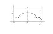
図6(b)及び図7(b)は、爪傾き検出部812bによりライン画像Lbから算出された爪T及び印刷指U1の表面の高さの変化をプロットして得られる、爪T及び印刷指U1の表面の幅方向に沿った高さの変化を示す曲線のイメージ図であり、爪T及び印刷指U1の表面の幅方向における高さの変化を示している。ここでは、ラインレーザ光が、爪Tの幅方向の端部が接している指の部分にも当たっている場合について示している。
図6(b)は図6(a)に示すように印刷指U1が、印刷指U1の長さ方向の軸(回転軸)を回転中心としてほとんど回転しておらず、傾きがほとんど無く、正しく指受入部31内に載置されている場合における爪T及び印刷指U1の表面の幅方向における高さの変化を示している。一方、図7(b)は、図7(a)に示すように印刷指U1が指受入部31内で、印刷指U1の長さ方向の軸(回転軸)を回転中心として比較的大きく回転していて、比較的大きく傾いている場合における爪T及び印刷指U1の表面の幅方向における高さの変化を示している。
図6(b)及び図7(b)において一点鎖線で囲んだ部分は、爪Tの幅方向の端部が指と接している部分であり、その高さが、その位置に対する幅方向の両側に対して下がる形となっていて、曲率がその両側に対して大きく変化するとともに、湾曲の方向もその両側に対して逆となる部分である。本実施形態では、ライン画像Lb中に現れるこの曲率が大きく変化している部分を特徴点Pとする。なお、図7(b)では、印刷指U1の傾きが大きいために、特徴点Pは左側の1箇所のみに見えていて、右側には特徴点Pが見えていない場合を示している。
図6(b)に示すように、ライン画像Lb中に2つの特徴点Pが現れている場合、この2つの特徴点Pの間は爪Tの表面の幅方向の高さの変化を示しており、各特徴点Pよりも外側は、指の爪T以外の部分の表面の幅方向の高さの変化を示している。
本実施形態では、爪傾き検出部812bにより検出されたこの2つの特徴点Pの間の高さの変化が、爪Tの湾曲形状(爪曲率)を示すものとして検出される。FIGS. 6B and 7B show the nail T and the printing obtained by plotting the change in the height of the surface of the nail T and the printing finger U1 calculated from the line image Lb by the nail
In FIG. 6B, as shown in FIG. 6A, the printing finger U1 is hardly rotated about the axis (rotation axis) in the length direction of the printing finger U1, and there is almost no inclination, and it is correct. The change of the height in the width direction of the surface of the nail | Tail T and the printing finger | toe U1 in the case of being mounted in the finger | toe receiving
6 (b) and FIG. 7 (b), the portion surrounded by the alternate long and short dash line is the portion where the end in the width direction of the nail T is in contact with the finger, and the height is on both sides in the width direction with respect to the position The curvature is greatly changed with respect to both sides thereof, and the bending direction is also opposite to both sides thereof. In the present embodiment, a portion where the curvature that appears in the line image Lb is greatly changed is defined as a feature point P. In FIG. 7B, since the inclination of the printing finger U1 is large, the feature point P is visible only at one place on the left side, and the feature point P is not visible on the right side.
As shown in FIG. 6B, when two feature points P appear in the line image Lb, a change in height in the width direction of the surface of the nail T is shown between the two feature points P. In addition, the outside of each feature point P indicates a change in the height in the width direction of the surface of the portion other than the fingernail T.
In the present embodiment, a change in height between the two feature points P detected by the nail
本実施形態の爪傾き検出部812bは、爪Tの表面の高さの幅方向に沿った変化を示す図6(b)及び図7(b)に示すような曲線を得ると、爪Tの、指の長さ方向の軸(回転軸)を回転中心とした回転による傾きの程度を表す評価値を算出する。
以下に爪Tの傾きの程度を評価する手法について説明する。When the nail
A method for evaluating the degree of inclination of the nail T will be described below.
まず、第1の手法としては、爪Tの幅方向に沿った高さの変化を示す曲線を、図8及び図10に示すように、縦(高さ)方向をG、横(幅)方向をxとしたグラフGxとみなし、x方向の最小値(i=0)から最大値(i=W)までの間の幅Wの中点(W/2)を求める。
そして、この中点(W/2)を境に、右側又は左側の何れか一方側を左右反転させ、他方側に重ね合わせて、左右の対称性を判断する。First, as a first method, as shown in FIGS. 8 and 10, a curve indicating the change in height along the width direction of the nail T is G in the vertical (height) direction and the horizontal (width) direction. X is a graph Gx, and the midpoint (W / 2) of the width W between the minimum value (i = 0) and the maximum value (i = W) in the x direction is obtained.
Then, with this midpoint (W / 2) as a boundary, either the right side or the left side is reversed left and right, and superimposed on the other side to determine left-right symmetry.
例えば、図8に示すグラフは、指が指の長さ方向の軸(回転軸)を回転中心としてほとんど回転しておらず、爪Tがほとんど傾いていない場合の図6(a)及び図6(b)に対応するものである。この場合、中点(W/2)よりも左側の形状は、図9(a)において実線で示す形状となっている。そして、中点(W/2)よりも右側を一方側として、この一方側を左右反転させると、その形状は図9(b)において一点鎖線で示す形状となっている。図9(c)は、図9(a)における実線と図9(b)における一点鎖線とを重ね合わせたものである。
図9(c)に示すように、指がほとんど回転していおらず、爪がほとんど傾いていない状態では、中点(W/2)を中心に左右を重ね合わせると両者はほぼ重なり、左右はほぼ対称となっていることが分かる。
なお、このような左右対称性は、下記の式1のように、左右対称のときに値が0となるような評価式によってその評価値を算出することができる。
なお、実際には爪Tの幅方向の中点を正確に求めることは困難であると考えられるため、中点が(W/2)−1や(W/2)+1である場合についても評価式を計算し、このうち最も小さい値をGxの評価値としてもよい。
多くの人の指(爪Tを含む指)では、高さ方向の形状はほぼ左右対称に近いため、指が指の長さ方向の回転軸を回転中心としてほとんど回転していない状態では、この評価値は小さくなる。For example, in the graph shown in FIG. 8, the finger is hardly rotated about the axis (rotation axis) in the length direction of the finger, and the nail T is hardly inclined. This corresponds to (b). In this case, the shape on the left side of the midpoint (W / 2) is the shape indicated by the solid line in FIG. Then, when the right side of the middle point (W / 2) is set as one side and this one side is reversed left and right, the shape becomes a shape indicated by a one-dot chain line in FIG. 9B. FIG. 9 (c) is obtained by superimposing the solid line in FIG. 9 (a) and the one-dot chain line in FIG. 9 (b).
As shown in FIG. 9 (c), in a state where the finger is hardly rotated and the nail is hardly tilted, when the left and right are overlapped around the midpoint (W / 2), the two are substantially overlapped. It turns out that it is almost symmetrical.
Note that such left-right symmetry can be calculated by an evaluation formula such that the value is 0 when left-right symmetry, as in
Note that it is actually difficult to accurately determine the midpoint in the width direction of the nail T. Therefore, the evaluation is also made when the midpoint is (W / 2) -1 or (W / 2) +1. The formula may be calculated, and the smallest value among them may be used as the Gx evaluation value.
In many human fingers (including the fingernail T), the shape in the height direction is almost symmetrical, so in the state where the finger is hardly rotating around the rotation axis in the finger length direction, The evaluation value becomes smaller.
これに対して、指が指の長さ方向の回転軸を回転中心として回転していて、爪Tが傾いている場合には、この評価値が大きくなる。
例えば、図10に示すグラフは、指が指の長さ方向の回転軸に対して比較的大きく回転している状態である図7(a)及び図7(b)に対応するものである。この場合、中点(W/2)よりも左側の形状は、図11(a)において実線で示す形状となっている。そして、中点(W/2)よりも右側を他方側として、これを左右反転させると、その形状は図11(b)において一点鎖線で示す形状となっている。図11(c)は、図11(a)における実線と図11(b)における一点鎖線とを重ね合わせたものである。
図11(c)に示すように、指が比較的大きく回転している状態では、中点(W/2)を中心に左右を重ね合わせると両者が大きくずれていて、左右対称でないことが分かる。
このような場合には、上記の評価式によって算出される評価値が大きくなる。On the other hand, when the finger rotates about the rotation axis in the length direction of the finger and the nail T is tilted, this evaluation value becomes large.
For example, the graph shown in FIG. 10 corresponds to FIG. 7A and FIG. 7B in which the finger rotates relatively large with respect to the rotation axis in the finger length direction. In this case, the shape on the left side of the midpoint (W / 2) is the shape indicated by the solid line in FIG. Then, when the right side of the middle point (W / 2) is set as the other side and this is reversed left and right, the shape becomes a shape indicated by a one-dot chain line in FIG. FIG.11 (c) superimposes the continuous line in Fig.11 (a), and the dashed-dotted line in FIG.11 (b).
As shown in FIG. 11C, it can be seen that when the finger is relatively rotated, when the left and right are overlapped around the middle point (W / 2), the two are greatly displaced and are not symmetrical. .
In such a case, the evaluation value calculated by the above evaluation formula becomes large.
本実施形態では、算出された評価値が所定の閾値よりも大きい場合には、ユーザに報知するようになっている。
報知の具体的な手法は特に限定されないが、例えば、表示部26に「爪が傾いています。真直ぐに入れ直してください」等の警告を表示させ、ユーザに印刷指U1(爪T)の再挿入や挿入した指の回転方向の位置の調整を促す。
なお、評価値が閾値以下の場合には、爪Tの傾きの程度に応じて適宜描画データ補正部813aが描画データを補正した上で、描画動作を行う。
なお、この手法においては、ライン画像Lb中に特徴点Pが現れていなくてもよいため、この場合には、ラインレーザ光が爪Tに当たる位置が、ラインレーザ光が、爪Tの幅方向の端部が接している指の部分には当たらない位置とされていてもよい。In this embodiment, when the calculated evaluation value is larger than a predetermined threshold value, the user is notified.
Although the specific method of notification is not particularly limited, for example, a warning such as “the nail is tilted. Please reinsert straight” is displayed on the
If the evaluation value is less than or equal to the threshold value, the drawing data correction unit 813a appropriately corrects the drawing data according to the degree of inclination of the nail T, and then performs the drawing operation.
In this method, the feature point P does not have to appear in the line image Lb. In this case, the position where the line laser light hits the nail T is the position where the line laser light is in the width direction of the nail T. You may be made into the position which does not contact the part of the finger | toe which the edge part touches.
また、第2の手法としては、図6(b)及び図7(b)に一点鎖線で囲んだ特徴点Pのように、爪T部分と指部分との境界部分で曲率が大きく変化する2点(特徴点)を抽出し、指におけるこの2点の箇所の高さの差を算出し、この算出結果を評価値としてもよい。
例えば、指がほとんど回転しておらず、爪Tが傾いていない状態である場合には、図6(b)に示すように、指における2つの特徴点Pの箇所の高さはほぼ同じとなり、評価値は小さくなる。これに対して、指が比較的大きく回転していて、爪Tが比較的大きく傾いている状態である場合には、指における2つの特徴点Pの箇所の高さが大きく異なり、あるいは、図7(b)に示すように、特徴点Pが1箇所にのみ検出されて、評価値は大きくなる。
そして、この評価値が所定の閾値よりも大きい場合には、ユーザに報知し、評価値が閾値以下の場合には、爪Tの傾きの程度に応じて適宜描画データ補正部813aが描画データを補正した上で描画動作を行う。Further, as a second method, as shown by a feature point P surrounded by a one-dot chain line in FIGS. 6B and 7B, the curvature greatly changes at the boundary portion between the nail T portion and the
For example, when the finger is hardly rotated and the nail T is not inclined, the heights of the two feature points P on the finger are substantially the same as shown in FIG. The evaluation value becomes small. On the other hand, when the finger rotates relatively large and the nail T is inclined relatively large, the heights of the two feature points P on the finger differ greatly, As shown in FIG. 7B, the feature point P is detected only in one place, and the evaluation value becomes large.
If the evaluation value is larger than the predetermined threshold value, the user is notified. If the evaluation value is equal to or smaller than the threshold value, the drawing data correction unit 813a appropriately selects the drawing data according to the degree of inclination of the nail T. The drawing operation is performed after correction.
爪Tの傾きの評価値を得るための上記2つの手法(すなわち、ライン画像Lbから検出できる爪Tの幅方向における形状の左右対称性を評価する手法、及びライン画像Lb中の複数の特徴点Pの高さ位置の差を評価する手法)は、いずれか一方を適用してもよいし、両方の手法を併用してもよい。両方の手法を併用する場合には、例えば、各手法で得られた評価値を足し合わせた値が所定の閾値を超えるか否かで判断する。
なお、爪傾き検出部812bが爪Tの傾きを検出する手法、爪Tの傾きを評価する手法は、ここに示したものに限定されない。The above two methods for obtaining an evaluation value of the inclination of the nail T (that is, a method for evaluating the left-right symmetry of the shape in the width direction of the nail T that can be detected from the line image Lb, and a plurality of feature points in the line image Lb) Any one of the methods for evaluating the difference in height position of P) may be applied, or both methods may be used in combination. When both methods are used in combination, for example, determination is made based on whether or not a value obtained by adding the evaluation values obtained by the respective methods exceeds a predetermined threshold value.
Note that the method of detecting the inclination of the nail T by the nail
なお、上記各手法における評価値の閾値は、描画データ補正部813aによる描画データの補正で対応可能か否かの観点から適宜設定される。
補正可能な傾きのレベルは、爪Tの湾曲形状(爪曲率)にも依存するため、評価値の閾値は、当該爪Tの爪曲率に応じて設定されることが好ましい。
例えば、爪Tを、爪曲率の大きさに応じて複数段階の円弧パターンに分類し(例えば、曲率が最も小さい範囲のものをパターン1とし、曲率が最も大きい範囲のものをパターン3とし、曲率がこれらの中間の範囲のものをパターン2とするというように3段階に分類。)、当該複数段階の爪Tの円弧パターンに応じた評価値の閾値を記憶部82等に記憶させておき、ユーザの爪Tが上記円弧パターンのうちのどれに最も近いかによって当該爪Tに適用する評価値の閾値を決定してもよい。
この評価値の閾値は、当該爪Tについて一旦設定された後は、ユーザ名や指種等と関連付けて記憶部82等に記憶させておき、同じユーザの同じ指の爪Tが描画対象となるときには、該当する閾値を記憶部82から読み出して適用するようにしてもよい。Note that the threshold value of the evaluation value in each of the above methods is appropriately set from the viewpoint of whether or not the drawing data correction unit 813a can handle the drawing data.
Since the level of inclination that can be corrected also depends on the curved shape (nail curvature) of the nail T, the threshold value of the evaluation value is preferably set according to the nail curvature of the nail T.
For example, the nail T is classified into a plurality of stages of arc patterns according to the size of the nail curvature (for example, the pattern with the smallest curvature is
After the threshold value of the evaluation value is once set for the nail T, it is stored in the
描画データ生成部813は、爪情報検出部812により検出された爪情報に基づいて、描画部40により印刷指U1の爪Tに施される描画用のデータを生成する。
具体的には、描画データ生成部813は、爪情報検出部812により検出された爪Tの形状等の爪情報に基づいてデザイン画像の画像データを縮小又は拡大する等による合せ込み処理(フィッティング処理)を行い、爪Tに、デザイン画像を描画するための描画データを生成する。The drawing
Specifically, the drawing
本実施形態の描画データ生成部813は、描画データを補正する描画データ補正部813aを含んでいる。
また、指の回転により爪Tが傾いているが、補正で対応可能な範囲内と判断されたとき(すなわち、評価値が所定の閾値以下の場合)は、描画データ補正部813aは、爪傾き検出部812bによる検出結果に基づいて爪Tに描画を施すための描画データを補正する。
さらに、本実施形態では、爪傾き検出部812bによって爪Tの爪曲率が検出され、描画データ補正部813aは、この爪曲率に応じて描画データを補正(曲面補正)する。
なお、爪Tを複数段階の円弧パターン(例えばパターン1からパターン3)に分類し、各円弧パターンごとに曲面補正の補正値が用意されている場合には、描画データ補正部813aは、爪Tの円弧パターンに応じた補正値にしたがって描画データを補正(曲面補正)する。The drawing
In addition, the nail T is tilted by the rotation of the finger, but when it is determined that the correction is within a compatible range (that is, when the evaluation value is equal to or less than a predetermined threshold value), the drawing data correction unit 813a The drawing data for drawing on the nail T is corrected based on the detection result by the
Further, in the present embodiment, the nail
When the nail T is classified into a plurality of stages of arc patterns (for example,
表示制御部814は、表示部26を制御して表示部26に各種の表示画面を表示させるものである。本実施形態では、表示制御部814は、例えばデザイン画像の選択画面やデザイン確認用のサムネイル画像、印刷指U1を撮影した指画像や指画像に含まれる爪画像(爪Tの画像)、各種の指示画面等を表示部26に表示させるようになっている。
本実施形態では、爪Tの傾きが所定の閾値を超えていると判断された場合に、表示制御部814は、表示部26に指をセットし直すように促す警告を表示させて、ユーザへの報知を行う。The
In the present embodiment, when it is determined that the inclination of the nail T exceeds a predetermined threshold, the
描画制御部815は、描画データ生成部813によって適宜曲面補正された上で生成されたデザイン画像の描画データを描画部40に出力し、爪Tに対してこの描画データにしたがった描画を施すように、描画部40のキャリッジ移動部49であるX方向移動モータ46、Y方向移動モータ48、描画ヘッド41のインク吐出部411、筆記具71を上下させるソレノイド742の動作を制御する。 The
レーザ制御部816は、レーザ照射部55の動作を制御するものである。
本実施形態では、レーザ制御部816は、爪領域検出部812aによって検出された爪領域のうち、爪Tの幅方向の長さがもっとも長い部分(すなわち、幅広部分)又はその近傍の位置、好ましくは、更にラインレーザ光が爪Tの幅方向の端部が接している指の部分にも当たる位置に、レーザ照射部55からのラインレーザ光を照射するようになっている。
制御部81は、適宜ステージ移動用モータ58を制御して、移動ステージ56をガイドレール57に沿ってY方向(すなわち、描画装置1の前後方向)に移動させ、レーザ照射部55からのラインレーザ光が、爪Tの幅方向の長さがもっとも長い部分又はその近傍、好ましくは、更にラインレーザ光が爪Tの幅方向の端部が接している指の部分にも当たる位置に照射されるように、レーザ照射部55の位置を調整する。具体的には、ラインレーザ光の照射位置は、カメラ51の画像に基づいて装置側において把握され、これに応じて自動的にレーザ照射部55の位置調整が行われる。
なお、レーザ照射部55の位置調整は自動で行われる場合に限定されず、カメラ51で撮影された画像を表示部26に適宜表示させ、この表示を見ながらユーザが手動でレーザ照射部55の位置調整を行ってもよい。The
In the present embodiment, the
The
The position adjustment of the
次に、本実施形態における描画装置1の動作及び描画装置1を用いた爪傾き検出方法について説明する。 Next, the operation of the
図12は、本実施形態の爪傾き検出方法の流れを示すフローチャートである。
図12に示すように、描画装置1を用いて爪傾きの検出を行う場合には、ユーザはまず、電源スイッチを入れて制御装置80を起動させる。
次に、ユーザは、印刷指U1を指受入部31に挿入し、非印刷指U2を指退避部32に挿入して、印刷指U1を固定した上で、検出動作を開始させるスイッチを操作する。
スイッチから指示が入力されると、撮影制御部811が撮影部50を制御して、照明灯52により印刷指U1を照明しながらカメラ51により印刷指U1を撮影させる。これにより、撮影制御部811は、指受入部31に挿入された印刷指U1の指画像を取得する(ステップS1)。FIG. 12 is a flowchart showing a flow of the nail inclination detection method of the present embodiment.
As shown in FIG. 12, when detecting the nail inclination using the
Next, the user inserts the printing finger U1 into the
When an instruction is input from the switch, the photographing
次に、爪領域検出部812aは、指画像に基づいて爪Tの輪郭(爪領域)を検出(算出)する(ステップS2)。
レーザ制御部816は、印刷指U1における、検出された爪領域のうち、爪Tの幅方向(x方向)の長さが最大又はその近傍、好ましくは、更にラインレーザ光が爪Tの幅方向の端部が接している指の部分にも当たる、特定箇所を求める(ステップS3)。そして、印刷指U1の当該特定箇所に、レーザ照射部55によってラインレーザ光を照射することにより、爪Tの幅方向に爪傾き検出用のラインLa(図6(a)及び図7(a)参照)を形成させる(ステップS4)。Next, the nail
The
爪TにラインLaが形成されると、再度撮影制御部811が撮影部50を制御して、照明灯52により印刷指U1を照明しながらカメラ51により印刷指U1を撮影させる。これにより、撮影制御部811は、爪Tに描かれたラインLaのライン画像Lbを含む指画像を取得する(ステップS5)。
指画像が取得されると、爪傾き検出部812bは、爪Tとの色の差異等に基づいて指画像からライン画像Lbを検出する(ステップS6)。
そして、爪傾き検出部812bは、このライン画像Lbに基づいて、当該爪T及び印刷指U1の表面の幅方向に沿った高さの変化を求める(ステップS7)。これに基づいて、爪Tの傾きの程度を評価し、傾きが補正可能範囲内か否かを判断する(ステップS8)。具体的には、爪Tの高さ方向の位置を表す曲線の左右対称性を評価する評価値を算出したり、爪Tの高さ方向の位置を表す曲線に現れる複数の特徴点の位置を比較して評価値を算出し、この評価値が所定の閾値を超えるか否かを判断する。
そして、爪Tの傾きが補正可能範囲内であると判断した場合(すなわち、評価値が閾値以下の場合、ステップS8;YES)には、描画データ補正部813aが爪Tの傾きに応じた補正値を求めて描画データを補正し(ステップS9)、補正後の描画データによりデザイン画像を描画する(ステップS10)。
これに対して、爪Tの傾きが補正可能範囲内でないと判断した場合(すなわち、評価値が閾値を超える場合、ステップS8;NO)には、印刷指U1をセットし直すように表示部26に表示させる等によりユーザに報知し(ステップS11)、描画処理を終了する。When the line La is formed on the nail T, the
When the finger image is acquired, the nail
Then, the nail
When it is determined that the inclination of the nail T is within the correctable range (that is, when the evaluation value is equal to or smaller than the threshold value, step S8; YES), the drawing data correction unit 813a corrects according to the inclination of the nail T. The drawing data is corrected by obtaining the value (step S9), and the design image is drawn with the corrected drawing data (step S10).
On the other hand, when it is determined that the inclination of the nail T is not within the correctable range (that is, when the evaluation value exceeds the threshold value, step S8; NO), the
以上のように、本実施形態によれば、ラインレーザ光を照射することにより爪領域の幅方向にラインLaを形成し、このラインLaを斜め上方向から撮影して得たライン画像Lbに基づいて、爪傾き検出部812bが爪Tの傾きを検出する。
これにより、指が延在方向の軸を中心として回転することで爪Tが傾いてしまった場合でも、比較的簡易かつ確実に爪Tの傾きの検出を行うことができる。
また、爪傾き検出部812bが、ライン画像Lb中の複数の特徴点Pの高さ方向の位置を比較することで爪Tの傾きを検出する場合には、簡易な処理により確実に爪Tの傾きを検出することができる。
また、爪傾き検出部812bが、ライン画像Lbの爪Tの幅方向における対称性を評価することで爪Tの傾きを検出する場合には、必ずしも特徴点Pを含むようにラインLaを形成し特徴点Pを含むライン画像Lbを取得しなくても、爪Tの幅方向の中心(W/2)を含むある程度の幅のライン画像Lbを取得できれば左右対称性を判断でき、爪Tの形状が特殊である等により特徴点Pを取りにくい場合等でも適切に爪Tの傾きを検出することができる。
また、上記特徴点Pの高さ方向の位置を比較する手法と爪Tの幅方向における対称性を評価する手法とを併せて爪の傾きの判断に用いる場合には、より確実に爪Tの傾きを検出することができる。
また、本実施形態では、爪傾き検出部812bが検出した爪Tの傾きが所定以上である場合に、表示部26等にメッセージを表示させ、ユーザに報知するようになっている。このため、爪Tが傾いた状態のまま、これに気づかずに描画を行い、ネイルプリントに失敗してしまうのを防止することができる。As described above, according to the present embodiment, the line La is formed in the width direction of the nail region by irradiating the line laser beam, and the line La is obtained based on the line image Lb obtained by photographing the line La obliquely from above. Thus, the nail
Thereby, even when the nail T is tilted by rotating the finger about the extending direction axis, the inclination of the nail T can be detected relatively easily and reliably.
In addition, when the nail
When the nail
In addition, when the method for comparing the position of the feature point P in the height direction and the method for evaluating the symmetry of the nail T in the width direction are used for the determination of the inclination of the nail, the nail T Tilt can be detected.
In the present embodiment, when the inclination of the nail T detected by the nail
なお、本発明を適用可能な実施形態は、上述した実施形態に限定されることなく、本発明の趣旨を逸脱しない範囲で適宜変更可能である。 The embodiments to which the present invention can be applied are not limited to the above-described embodiments, and can be appropriately changed without departing from the spirit of the present invention.
例えば、上記実施形態では、描画制御部815は、爪領域のうち、爪Tの幅方向における最大幅又はその近傍の1箇所にラインLaを1本のみ形成し、このラインLaを撮影して得たライン画像Lbに基づいて爪傾き検出部812bが爪の傾きを検出する場合を例示したが、爪傾き検出部812bによる爪Tの傾きの検出はこれに限定されない。
例えば、爪Tの幅方向に沿って複数本のラインLaを形成し、これを撮影部50によって撮影させて複数本のライン画像Lbを取得し、この複数本のライン画像Lbに基づいて爪Tの傾きの検出を行ってもよい。検出対象となるライン画像Lbの数を増やした場合には、爪Tについて、より詳細な三次元形状を取得することが可能となり、これに基づいて描画データを補正することで、爪T上により高精細な描画を行うことが可能となる。For example, in the above embodiment, the
For example, a plurality of lines La are formed along the width direction of the nail T, and this is photographed by the photographing
また、本実施形態では、1つのカメラ51によって爪Tの輪郭等を検出するための撮影と、ライン画像Lbを得るための撮影とを行う場合を例示したが、撮影は1つのカメラによって行う場合に限定されず、例えば、ライン画像Lbを得るためのカメラ51を装置の奥側に配置し、これとは別に、爪Tの輪郭等を検出するための画像を取得するカメラを爪Tの真上等に配置してもよい。 Further, in the present embodiment, the case where photographing for detecting the outline of the nail T and the like for obtaining the line image Lb are performed by one
また、本実施形態では、爪傾き検出用のラインLaをレーザ照射部55からラインレーザ光を照射することで形成する場合を例示したが、ラインLaを形成する手段はレーザ照射部55に限定されない。例えば、描画ヘッド41や筆記具71等の描画用具によって爪Tの表面の幅方向に直線を描くことでラインLaを形成してもよい。
この場合、例えば、爪Tに施されるネイルデザインの背景となる色(例えば白色等)のインクを用いてラインLaを描いてもよい。
このようにした場合には、爪Tへのネイルデザイン描画前にラインLaを除去する必要がなく、爪Tの傾きの検出処理後に続けてネイルデザインの描画を行うことができる。Further, in this embodiment, the case where the line La for detecting the nail inclination is formed by irradiating the line laser beam from the
In this case, for example, the line La may be drawn using an ink of a color (for example, white) that becomes the background of the nail design applied to the nail T.
In this case, it is not necessary to remove the line La before the nail design is drawn on the nail T, and the nail design can be drawn continuously after the detection processing of the inclination of the nail T.
さらに、例えば紫外線発光型の透明塗料等、所定の光を照射することで発光し可視化されるインクによって爪Tの表面に直線を描き、爪傾き検出用のラインLaを形成してもよい。
この場合には、当該塗料を発光させるための所定の強度をもった光を照射可能な光源(例えば紫外線を照射するブラックライト等)を装置内に備え、ラインLaを撮影してライン画像Lbを得る際には、この光源から所定の光を爪Tの表面に照射して、ラインLaを発光させた状態で撮影を行う。
このようにした場合には、通常状態(すなわち所定の光源からの光を照射しない状態)ではラインLaが可視化されないため、爪Tへのネイルデザイン描画前にラインLaを除去する必要がなく、爪Tの傾きの検出処理後に続けてネイルデザインの描画を行うことができる。Further, a line La for detecting the inclination of the nail may be formed by drawing a straight line on the surface of the nail T with ink that is emitted and visualized by irradiating predetermined light, such as an ultraviolet light emitting transparent paint.
In this case, a light source (for example, a black light that irradiates ultraviolet rays) capable of emitting light having a predetermined intensity for causing the paint to emit light is provided in the apparatus, and the line La is photographed to obtain the line image Lb. When obtaining, the surface of the nail T is irradiated with predetermined light from this light source, and photographing is performed in a state where the line La is emitted.
In this case, since the line La is not visualized in a normal state (that is, a state where light from a predetermined light source is not irradiated), it is not necessary to remove the line La before drawing the nail design on the nail T. The nail design can be drawn after the detection of the inclination of T.
また、本実施形態では、カメラ51及びレーザ照射部55が移動ステージ56に取り付けられ、Y方向(すなわち、描画装置1の前後方向)に移動可能に構成されている場合を例示したが、カメラ51及びレーザ照射部55が移動可能に構成されていることは本発明の必須の要素ではなく、爪Tにラインレーザ光を照射可能な位置にレーザ照射部55が固定配置され、ラインレーザ光によって形成されたラインを斜め上方向から撮影可能な位置にカメラ51が固定配置されていてもよい。 In the present embodiment, the case where the
また、本実施形態では描画装置1が、描画用具として、インクジェット方式の描画ヘッド41と筆記具71とを備えるハイブリット式のネイルプリント装置である場合を例示して説明したが、描画装置はこれに限定されず、筆記具71のみを備えるプロッタ方式のネイルプリント装置やインクジェット方式の描画ヘッドのみを備えるネイルプリント装置であっても本発明の構成を用いることは可能である。 In the present embodiment, the
以上、本発明のいくつかの実施形態を説明したが、本発明の範囲は、上述の実施の形態に限定するものではなく、特許請求の範囲に記載された発明の範囲をその均等の範囲を含む。
以下に、この出願の願書に最初に添付した特許請求の範囲に記載した発明を付記する。付記に記載した請求項の項番は、この出願の願書に最初に添付した特許請求の範囲の通りである。As mentioned above, although several embodiment of this invention was described, the scope of the present invention is not limited to the above-mentioned embodiment, The range of the invention described in the claim is equal to the equivalent range. Including.
The invention described in the scope of claims attached to the application of this application will be added below. The item numbers of the claims described in the appendix are as set forth in the claims attached to the application of this application.
〔付記〕
<請求項1>
爪を有する指が載置される載置面を有する載置部と、
前記爪の幅方向に沿って、前記爪の上に撮影可能に形成された撮影対象物を撮影した画像における、前記撮影対象物の前記幅方向に沿った形状に基づいて、前記爪の前記載置面に対する傾斜状態を検出する爪傾き検出部と、
を備えていることを特徴とする描画装置。
<請求項2>
前記指は、前記載置面に第1方向に沿って挿入されて載置され、
前記撮影対象物は、前記載置面に対して垂直で前記第1方向に沿った垂直面における、前記載置面の延在方向に対して第1の角度を有する第2方向から前記幅方向に沿った直線状の部分を有し、
前記爪傾き検出部は、前記撮影対象物が形成された前記爪を、前記垂直面における、前記第1の角度異なる第2の角度を有する第3方向から撮影した画像における前記撮影対象物の形状と、前記第1の角度と前記第2の角度の差と、に基づいて、前記爪の前記傾斜状態を検出することを特徴とする請求項1に記載の描画装置。
<請求項3>
前記爪傾き検出部は、前記撮影対象物の前記形状における、前記爪の幅方向の端部から中央までの形状についての対称性の程度に基づいて、前記傾斜状態を検出することを特徴とする請求項1又は2に記載の描画装置。
<請求項4>
前記撮影対象物は、前記爪の表面上と、前記指の前記爪の幅方向の端部が接する部分の表面上と、に跨って形成され、
前記爪傾き検出部は、前記撮影対象物の、前記爪の表面上及び前記指の前記爪の幅方向の端部が接している部分の表面上の形状を取得することを特徴とする請求項1から請求項3のいずれか一項に記載の描画装置。
<請求項5>
前記爪傾き検出部は、前記撮影対象物の前記形状における、前記爪の幅方向の端部が前記指に接している部分に対応する曲率の変化が検出される少なくとも1つの箇所を少なくとも1つの特徴点として抽出し、前記指における前記特徴点に対応する箇所の高さに基づいて前記傾斜状態を検出することを特徴とする請求項4に記載の描画装置。
<請求項6>
選択されたデザイン画像に応じた描画データを、前記爪傾き検出部により検出された前記爪の前記傾斜状態に応じて補正する描画データ補正部と、
前記爪傾き検出部が検出した前記爪の前記傾斜状態における傾斜の程度が、前記描画データ補正部による前記補正ができない大きさであるとき、これを報知する報知部を有していることを特徴とする請求項1から請求項5のいずれか一項に記載の描画装置。
<請求項7>
指の爪に描画を施す描画装置における爪傾き検出方法であって、
前記爪の幅方向に沿って、前記爪の上に撮影可能に形成された撮影対象物を撮影した画像における、前記撮影対象物の前記幅方向に沿った形状に基づいて、前記爪の前記載置面に対する傾斜状態を検出することを特徴とする爪傾き検出方法。
<請求項8>
前記指は、前記載置面に第1方向に沿って挿入されて載置され、
前記撮影対象物は、前記載置面に対して垂直で前記第1方向に沿った垂直面における、前記載置面の延在方向に対して第1の角度を有する第2方向から前記幅方向に沿った直線状の部分を有し、
前記撮影対象物が形成された前記爪を、前記垂直面における、前記第1の角度異なる第2の角度を有する第3方向から撮影した画像における前記撮影対象物の形状と、前記第1の角度と前記第2の角度の差と、に基づいて、前記爪の前記傾斜状態を検出することを特徴とする請求項7に記載の爪傾き検出方法。[Appendix]
<Claim 1>
A placement portion having a placement surface on which a finger having a nail is placed;
The description above of the nail based on the shape along the width direction of the photographing object in an image obtained by photographing the photographing object formed on the nail so as to be photographable along the width direction of the nail. A claw inclination detecting unit for detecting an inclination state with respect to the placement surface;
A drawing apparatus comprising:
<Claim 2>
The finger is inserted and placed on the placement surface along the first direction,
The photographing object is perpendicular to the placement surface and is in a width direction from a second direction having a first angle with respect to an extending direction of the placement surface in a vertical plane along the first direction. Having a linear portion along
The nail inclination detector detects the shape of the photographing object in an image obtained by photographing the nail on which the photographing object is formed from a third direction having a second angle different from the first angle on the vertical plane. The drawing apparatus according to
<Claim 3>
The nail inclination detecting unit detects the inclination state based on a degree of symmetry with respect to a shape from an end portion in a width direction of the nail to a center in the shape of the photographing object. The drawing apparatus according to
<Claim 4>
The object to be photographed is formed across the surface of the nail and the surface of the part of the finger that contacts the end in the width direction of the nail,
The nail inclination detection unit acquires the shape of the object to be photographed on the surface of the nail and on the surface of a portion of the finger in contact with an end in the width direction of the nail. The drawing apparatus according to any one of
<Claim 5>
The nail inclination detecting unit has at least one location where a change in curvature corresponding to a portion of the shape of the object to be photographed corresponding to a portion of the nail width direction in contact with the finger is detected. The drawing apparatus according to
<Claim 6>
A drawing data correction unit that corrects drawing data corresponding to the selected design image according to the inclination state of the nail detected by the nail inclination detection unit;
And a notifying unit for notifying the degree of inclination of the nail in the inclined state detected by the nail inclination detecting unit when the correction by the drawing data correcting unit is not possible. The drawing apparatus according to any one of
<Claim 7>
A nail inclination detection method in a drawing device for drawing on a fingernail,
The description above of the nail based on the shape along the width direction of the photographing object in an image obtained by photographing the photographing object formed on the nail so as to be photographable along the width direction of the nail. A claw inclination detection method, comprising detecting an inclination state with respect to a placement surface.
<Claim 8>
The finger is inserted and placed on the placement surface along the first direction,
The photographing object is perpendicular to the placement surface and is in a width direction from a second direction having a first angle with respect to an extending direction of the placement surface in a vertical plane along the first direction. Having a linear portion along
The shape of the object to be photographed in an image obtained by photographing the nail formed with the object to be photographed from a third direction having a second angle different from the first angle on the vertical plane, and the first angle The nail inclination detection method according to claim 7, wherein the inclination state of the nail is detected based on the difference between the second angle and the second angle.
1 描画装置
10 装置本体
40 描画部
41 描画ヘッド
49 キャリッジ移動部
50 撮影部
51 カメラ
71 筆記具
80 制御装置
81 制御部
82 記憶部
811 撮影制御部
812 爪情報検出部
812a 爪領域検出部
812b 爪傾き検出部
813 描画データ生成部
813a 描画データ補正部
814 表示制御部
815 描画制御部
T 爪DESCRIPTION OF
Claims (8)
Translated fromJapanese前記爪の幅方向に沿って、前記爪の上に撮影可能に形成された撮影対象物を撮影した画像における、前記撮影対象物の前記幅方向に沿った形状に基づいて、前記爪の前記載置面に対する傾斜状態を検出する爪傾き検出部と、
を備えていることを特徴とする描画装置。A placement portion having a placement surface on which a finger having a nail is placed;
The description above of the nail based on the shape along the width direction of the photographing object in an image obtained by photographing the photographing object formed on the nail so as to be photographable along the width direction of the nail. A claw inclination detecting unit for detecting an inclination state with respect to the placement surface;
A drawing apparatus comprising:
前記撮影対象物は、前記載置面に対して垂直で前記第1方向に沿った垂直面における、前記載置面の延在方向に対して第1の角度を有する第2方向から前記幅方向に沿った直線状の部分を有し、
前記爪傾き検出部は、前記撮影対象物が形成された前記爪を、前記垂直面における、前記第1の角度異なる第2の角度を有する第3方向から撮影した画像における前記撮影対象物の形状と、前記第1の角度と前記第2の角度の差と、に基づいて、前記爪の前記傾斜状態を検出することを特徴とする請求項1に記載の描画装置。The finger is inserted and placed on the placement surface along the first direction,
The photographing object is perpendicular to the placement surface and is in a width direction from a second direction having a first angle with respect to an extending direction of the placement surface in a vertical plane along the first direction. Having a linear portion along
The nail inclination detector detects the shape of the photographing object in an image obtained by photographing the nail on which the photographing object is formed from a third direction having a second angle different from the first angle on the vertical plane. The drawing apparatus according to claim 1, wherein the inclination state of the nail is detected based on the difference between the first angle and the second angle.
前記爪傾き検出部は、前記撮影対象物の、前記爪の表面上及び前記指の前記爪の幅方向の端部が接している部分の表面上の形状を取得することを特徴とする請求項1から請求項3のいずれか一項に記載の描画装置。The object to be photographed is formed across the surface of the nail and the surface of the part of the finger that contacts the end in the width direction of the nail,
The nail inclination detection unit acquires the shape of the object to be photographed on the surface of the nail and on the surface of a portion of the finger in contact with an end in the width direction of the nail. The drawing apparatus according to any one of claims 1 to 3.
前記爪傾き検出部が検出した前記爪の前記傾斜状態における傾斜の程度が、前記描画データ補正部による前記補正ができない大きさであるとき、これを報知する報知部を有していることを特徴とする請求項1から請求項5のいずれか一項に記載の描画装置。A drawing data correction unit that corrects drawing data corresponding to the selected design image according to the inclination state of the nail detected by the nail inclination detection unit;
And a notifying unit for notifying the degree of inclination of the nail in the inclined state detected by the nail inclination detecting unit when the correction by the drawing data correcting unit is not possible. The drawing apparatus according to any one of claims 1 to 5.
前記爪の幅方向に沿って、前記爪の上に撮影可能に形成された撮影対象物を撮影した画像における、前記撮影対象物の前記幅方向に沿った形状に基づいて、前記爪の前記載置面に対する傾斜状態を検出することを特徴とする爪傾き検出方法。A nail inclination detection method in a drawing device for drawing on a fingernail,
The description above of the nail based on the shape along the width direction of the photographing object in an image obtained by photographing the photographing object formed on the nail so as to be photographable along the width direction of the nail. A claw inclination detection method, comprising detecting an inclination state with respect to a placement surface.
前記撮影対象物は、前記載置面に対して垂直で前記第1方向に沿った垂直面における、前記載置面の延在方向に対して第1の角度を有する第2方向から前記幅方向に沿った直線状の部分を有し、
前記撮影対象物が形成された前記爪を、前記垂直面における、前記第1の角度異なる第2の角度を有する第3方向から撮影した画像における前記撮影対象物の形状と、前記第1の角度と前記第2の角度の差と、に基づいて、前記爪の前記傾斜状態を検出することを特徴とする請求項7に記載の爪傾き検出方法。The finger is inserted and placed on the placement surface along the first direction,
The photographing object is perpendicular to the placement surface and is in a width direction from a second direction having a first angle with respect to an extending direction of the placement surface in a vertical plane along the first direction. Having a linear portion along
The shape of the object to be photographed in an image obtained by photographing the nail formed with the object to be photographed from a third direction having a second angle different from the first angle on the vertical plane, and the first angle The nail inclination detection method according to claim 7, wherein the inclination state of the nail is detected based on the difference between the second angle and the second angle.
Priority Applications (3)
| Application Number | Priority Date | Filing Date | Title |
|---|---|---|---|
| JP2015054435AJP6428411B2 (en) | 2015-03-18 | 2015-03-18 | Drawing apparatus and nail inclination detection method |
| US15/064,425US9799116B2 (en) | 2015-03-18 | 2016-03-08 | Drawing apparatus and method for acquiring inclination of nail |
| CN201610152832.4ACN105984213B (en) | 2015-03-18 | 2016-03-17 | The slant detection method of drawing apparatus and nail |
Applications Claiming Priority (1)
| Application Number | Priority Date | Filing Date | Title |
|---|---|---|---|
| JP2015054435AJP6428411B2 (en) | 2015-03-18 | 2015-03-18 | Drawing apparatus and nail inclination detection method |
Publications (2)
| Publication Number | Publication Date |
|---|---|
| JP2016171969A JP2016171969A (en) | 2016-09-29 |
| JP6428411B2true JP6428411B2 (en) | 2018-11-28 |
Family
ID=56924090
Family Applications (1)
| Application Number | Title | Priority Date | Filing Date |
|---|---|---|---|
| JP2015054435AActiveJP6428411B2 (en) | 2015-03-18 | 2015-03-18 | Drawing apparatus and nail inclination detection method |
Country Status (3)
| Country | Link |
|---|---|
| US (1) | US9799116B2 (en) |
| JP (1) | JP6428411B2 (en) |
| CN (1) | CN105984213B (en) |
Families Citing this family (16)
| Publication number | Priority date | Publication date | Assignee | Title |
|---|---|---|---|---|
| US11265444B2 (en)* | 2013-08-23 | 2022-03-01 | Preemadonna Inc. | Apparatus for applying coating to nails |
| US9687059B2 (en)* | 2013-08-23 | 2017-06-27 | Preemadonna Inc. | Nail decorating apparatus |
| JP7084935B2 (en)* | 2017-01-31 | 2022-06-15 | ネイロマティック リミテッド | Nail polish kit for use with automatic nail polish applicator |
| JP2018124167A (en)* | 2017-01-31 | 2018-08-09 | オムロン株式会社 | Inclination measuring device |
| JP7182058B2 (en) | 2017-01-31 | 2022-12-02 | ネイロマティック リミテッド | Brush-integrated capsule with film-forming polymer for nail polish |
| WO2018232510A1 (en)* | 2017-06-21 | 2018-12-27 | H3Alth Technologies Inc. | SYSTEM AND METHOD FOR MANUFACTURING PERSONALIZED NAILS |
| JP6926795B2 (en)* | 2017-08-04 | 2021-08-25 | カシオ計算機株式会社 | Nail printing device |
| JP7035394B2 (en)* | 2017-09-13 | 2022-03-15 | カシオ計算機株式会社 | Drawing device and drawing method |
| JP7020020B2 (en)* | 2017-09-20 | 2022-02-16 | カシオ計算機株式会社 | Drawing data generator, drawing data generation method and program |
| WO2019070886A1 (en) | 2017-10-04 | 2019-04-11 | Preemadonna Inc. | Systems and methods of adaptive nail printing and collaborative beauty platform hosting |
| WO2020152683A1 (en)* | 2019-01-22 | 2020-07-30 | Nailomatic Ltd. | Nail polish application and solidification apparatus |
| WO2020176430A1 (en)* | 2019-02-26 | 2020-09-03 | Elementree Inc. | Automatic nail polish application system and method |
| WO2020183621A1 (en)* | 2019-03-12 | 2020-09-17 | カワノ株式会社 | Adhesive coating device and adhesive coating method |
| KR20220106763A (en) | 2019-10-29 | 2022-07-29 | 네일프로, 인코포레이티드 | Automated total nail care system, device and method |
| JP7363409B2 (en)* | 2019-11-25 | 2023-10-18 | 船井電機株式会社 | printing device |
| CN112273835B (en)* | 2020-10-27 | 2024-07-26 | 中国地质大学(武汉) | Intelligent toenail grinding device and toenail grinding method |
Family Cites Families (22)
| Publication number | Priority date | Publication date | Assignee | Title |
|---|---|---|---|---|
| US6175422B1 (en)* | 1991-01-31 | 2001-01-16 | Texas Instruments Incorporated | Method and apparatus for the computer-controlled manufacture of three-dimensional objects from computer data |
| US5931166A (en)* | 1998-12-22 | 1999-08-03 | Weber; Paul J. | Fingernail decorating |
| US6286517B1 (en)* | 1998-12-22 | 2001-09-11 | Pearl Technology Holdings, Llc | Fingernail and toenail decoration using ink jets |
| JP3016147B1 (en)* | 1998-12-25 | 2000-03-06 | 株式会社アトラス | Nail art equipment |
| US6035860A (en)* | 1999-01-14 | 2000-03-14 | Belquette Ltd. | System and method for applying fingernail art |
| US6668099B1 (en)* | 2000-10-26 | 2003-12-23 | General Phosphorix Llc | Method of measuring an angle of inclination of trapezoidal micro object side faces |
| JP4610341B2 (en)* | 2002-11-13 | 2011-01-12 | ミック アメリカ インコーポレイテッド | System and method for creating a custom-fitting artificial nail using a non-contact optical measurement device |
| US7253908B2 (en)* | 2004-07-22 | 2007-08-07 | The Boeing Company | Non-destructive inspection using laser profiling and associated method |
| US20100069744A1 (en)* | 2006-03-10 | 2010-03-18 | Ray Andrew Simpkin | Imaging System |
| JP2008093212A (en)* | 2006-10-12 | 2008-04-24 | Cp Toms:Kk | Model |
| GB0905006D0 (en)* | 2009-03-24 | 2009-05-06 | Rawlinson Paul | Testing and mounting IC's on PCB's |
| JP5494562B2 (en)* | 2011-04-28 | 2014-05-14 | カシオ計算機株式会社 | Curved surface printing apparatus and printing control method for curved surface printing apparatus |
| JP5402980B2 (en)* | 2011-05-09 | 2014-01-29 | カシオ計算機株式会社 | Nail printing apparatus and printing control method for nail printing apparatus |
| JP6186975B2 (en)* | 2012-09-06 | 2017-08-30 | カシオ計算機株式会社 | Nail printing apparatus and printing control method for nail printing apparatus |
| US9267792B2 (en)* | 2013-01-21 | 2016-02-23 | Systèmes Pavemetrics Inc. | Method and apparatus for compensating lateral displacements and low speed variations in the measure of a longitudinal profile of a surface |
| US20150377606A1 (en)* | 2013-02-25 | 2015-12-31 | Nikon Metrology N.V. | Projection system |
| US9237279B2 (en)* | 2013-05-06 | 2016-01-12 | Bergen Teknologioverfoering As | Method of investigating a solid sample |
| JP6268771B2 (en)* | 2013-07-05 | 2018-01-31 | カシオ計算機株式会社 | Nail printing apparatus, printing method and program for nail printing apparatus |
| JP6127793B2 (en)* | 2013-07-18 | 2017-05-17 | カシオ計算機株式会社 | Nail printing apparatus and printing method for nail printing apparatus |
| US9751329B2 (en)* | 2013-08-22 | 2017-09-05 | Yuan Chang | Method for printing on elevation contours of the print object |
| JP6331409B2 (en)* | 2014-01-20 | 2018-05-30 | カシオ計算機株式会社 | Drawing apparatus and drawing control method of drawing apparatus |
| JP6439342B2 (en)* | 2014-09-22 | 2018-12-19 | カシオ計算機株式会社 | Nail information detection device, drawing device, and nail information detection method |
- 2015
- 2015-03-18JPJP2015054435Apatent/JP6428411B2/enactiveActive
- 2016
- 2016-03-08USUS15/064,425patent/US9799116B2/enactiveActive
- 2016-03-17CNCN201610152832.4Apatent/CN105984213B/enactiveActive
Also Published As
| Publication number | Publication date |
|---|---|
| US9799116B2 (en) | 2017-10-24 |
| JP2016171969A (en) | 2016-09-29 |
| CN105984213A (en) | 2016-10-05 |
| CN105984213B (en) | 2018-12-28 |
| US20160270506A1 (en) | 2016-09-22 |
Similar Documents
| Publication | Publication Date | Title |
|---|---|---|
| JP6428411B2 (en) | Drawing apparatus and nail inclination detection method | |
| JP6428415B2 (en) | Drawing apparatus and nail shape detection method | |
| CN106901484B (en) | Drawing device and drawing method for drawing device | |
| US10022984B2 (en) | Drawing apparatus and drawing method for drawing apparatus | |
| CN105269957B (en) | Drawing device and drawing control method of drawing device | |
| JP6128067B2 (en) | Drawing apparatus and drawing control method of drawing apparatus | |
| JP6790513B2 (en) | Drawing device and drawing method of drawing device | |
| JP6589469B2 (en) | Drawing apparatus and drawing method of drawing apparatus | |
| CN106913053A (en) | The plotting method of drawing apparatus and drawing apparatus | |
| CN106313905B (en) | The drawing control method of plotting unit and plotting unit | |
| JP2017118897A (en) | Drawing apparatus and method for controlling drawing apparatus | |
| JP6390740B2 (en) | Drawing apparatus and drawing control method of drawing apparatus | |
| JP6939957B2 (en) | Drawing device and drawing method of drawing device | |
| JP2017055933A (en) | Nail shape detection device, drawing device, and nail shape detection method | |
| JP2016171968A (en) | Drawing apparatus and drawing method | |
| JP6733251B2 (en) | Drawing device and drawing method of drawing device | |
| JP7184130B2 (en) | Rendering device and rendering method | |
| JP2017006351A (en) | Drawing device and drawing method of drawing device |
Legal Events
| Date | Code | Title | Description |
|---|---|---|---|
| A621 | Written request for application examination | Free format text:JAPANESE INTERMEDIATE CODE: A621 Effective date:20171225 | |
| A977 | Report on retrieval | Free format text:JAPANESE INTERMEDIATE CODE: A971007 Effective date:20180912 | |
| TRDD | Decision of grant or rejection written | ||
| A01 | Written decision to grant a patent or to grant a registration (utility model) | Free format text:JAPANESE INTERMEDIATE CODE: A01 Effective date:20181002 | |
| A61 | First payment of annual fees (during grant procedure) | Free format text:JAPANESE INTERMEDIATE CODE: A61 Effective date:20181015 | |
| R150 | Certificate of patent or registration of utility model | Ref document number:6428411 Country of ref document:JP Free format text:JAPANESE INTERMEDIATE CODE: R150 |