JP6423964B2 - Method and system for generating geometric patch surface models - Google Patents
Method and system for generating geometric patch surface modelsDownload PDFInfo
- Publication number
- JP6423964B2 JP6423964B2JP2017526064AJP2017526064AJP6423964B2JP 6423964 B2JP6423964 B2JP 6423964B2JP 2017526064 AJP2017526064 AJP 2017526064AJP 2017526064 AJP2017526064 AJP 2017526064AJP 6423964 B2JP6423964 B2JP 6423964B2
- Authority
- JP
- Japan
- Prior art keywords
- location data
- data points
- surface model
- patch surface
- reference plane
- Prior art date
- Legal status (The legal status is an assumption and is not a legal conclusion. Google has not performed a legal analysis and makes no representation as to the accuracy of the status listed.)
- Active
Links
Images


Classifications
- G—PHYSICS
- G06—COMPUTING OR CALCULATING; COUNTING
- G06T—IMAGE DATA PROCESSING OR GENERATION, IN GENERAL
- G06T17/00—Three dimensional [3D] modelling, e.g. data description of 3D objects
- G—PHYSICS
- G06—COMPUTING OR CALCULATING; COUNTING
- G06T—IMAGE DATA PROCESSING OR GENERATION, IN GENERAL
- G06T19/00—Manipulating 3D models or images for computer graphics
- G06T19/20—Editing of 3D images, e.g. changing shapes or colours, aligning objects or positioning parts
- A—HUMAN NECESSITIES
- A61—MEDICAL OR VETERINARY SCIENCE; HYGIENE
- A61B—DIAGNOSIS; SURGERY; IDENTIFICATION
- A61B34/00—Computer-aided surgery; Manipulators or robots specially adapted for use in surgery
- A61B34/10—Computer-aided planning, simulation or modelling of surgical operations
- A61B2034/101—Computer-aided simulation of surgical operations
- A61B2034/105—Modelling of the patient, e.g. for ligaments or bones
- G—PHYSICS
- G06—COMPUTING OR CALCULATING; COUNTING
- G06T—IMAGE DATA PROCESSING OR GENERATION, IN GENERAL
- G06T2210/00—Indexing scheme for image generation or computer graphics
- G06T2210/44—Morphing
- G—PHYSICS
- G06—COMPUTING OR CALCULATING; COUNTING
- G06T—IMAGE DATA PROCESSING OR GENERATION, IN GENERAL
- G06T2210/00—Indexing scheme for image generation or computer graphics
- G06T2210/56—Particle system, point based geometry or rendering
- G—PHYSICS
- G06—COMPUTING OR CALCULATING; COUNTING
- G06T—IMAGE DATA PROCESSING OR GENERATION, IN GENERAL
- G06T2219/00—Indexing scheme for manipulating 3D models or images for computer graphics
- G06T2219/20—Indexing scheme for editing of 3D models
- G06T2219/2021—Shape modification
Landscapes
- Engineering & Computer Science (AREA)
- Physics & Mathematics (AREA)
- Computer Graphics (AREA)
- Theoretical Computer Science (AREA)
- General Physics & Mathematics (AREA)
- Software Systems (AREA)
- Geometry (AREA)
- General Engineering & Computer Science (AREA)
- Computer Hardware Design (AREA)
- Architecture (AREA)
- Measuring And Recording Apparatus For Diagnosis (AREA)
- Measurement And Recording Of Electrical Phenomena And Electrical Characteristics Of The Living Body (AREA)
- Image Generation (AREA)
Description
Translated fromJapanese関連出願の相互参照
本出願は、2014年11月18日に出願された仮出願番号第62/081,089号の優先権を主張し、その明細書全体が本明細書に組み込まれている。CROSS REFERENCE TO RELATED APPLICATIONS This application claims priority to provisional application number 62 / 081,089 filed on November 18, 2014, the entire specification of which is incorporated herein.
本開示は、幾何学的構造の多次元モデルを生成するためのシステムおよび方法に関する。より詳細には、本開示は、心臓内構造などの幾何学的構造のパッチ表面モデルを生成するためのコンピュータで実施されるシステムおよび方法に関する。 The present disclosure relates to systems and methods for generating multi-dimensional models of geometric structures. More particularly, the present disclosure relates to computer-implemented systems and methods for generating patch surface models of geometric structures such as intracardiac structures.
解剖学的構造などの幾何学的構造の多次元表面モデルを生成するために、様々なコンピュータ・ベースのシステムおよびコンピュータで実施される方法を使用できることが知られている。より具体的には、心臓および/またはその特定の部位の多次元表面モデルを生成するために種々のシステムおよび方法が使用されている。 It is known that various computer-based systems and computer-implemented methods can be used to generate multidimensional surface models of geometric structures such as anatomical structures. More specifically, various systems and methods have been used to generate a multidimensional surface model of the heart and / or its particular site.
1つの従来の方法または技法には、特定の構造の異なる関心領域に対応する複数の個別表面モデルを生成し、個別表面モデル同士を結合して単一の複合多次元表面モデルを形成することが含まれる。それぞれの関心領域の表面および表面に包まれたボリュームから場所データ点を収集し、これらの場所データ点を用いて関心領域ごとに個別表面モデルを生成することにより、個別表面モデルを生成することが知られている。 One conventional method or technique involves generating multiple individual surface models corresponding to different regions of interest of a particular structure and combining the individual surface models to form a single composite multidimensional surface model. included. Individual surface models can be generated by collecting location data points from the surface of each region of interest and the volume encased in the surface, and using these location data points to generate individual surface models for each region of interest Are known.
たとえば凸包、星形ドメイン近似(star−shaped domain approximation)、およびアルファ・シェイプの技法を含む任意数の技法を用いて、それぞれの場所データ点から個別表面モデルを生成することができる。しかしながら、少なくともいくつかの既知のモデル化システムは、実際の幾何学的構造にかかわらず、トポロジー的に球に相当する閉曲面を生成する。したがって、幾何学的構造の一部のみがモデル化される場合、その実際の一部が開曲面であっても、少なくともいくつかの既知のモデル化システムは、生成されるモデルを閉曲面とし、その結果、不正確なパンケーキ型のモデルとなる。そのような不正確性は、生成されたモデルを用いて幾何学的構造を分析するユーザの能力に影響し得る。 Individual surface models can be generated from each location data point using any number of techniques including, for example, convex hull, star-shaped domain approximation, and alpha shape techniques. However, at least some known modeling systems produce a closed surface that topologically corresponds to a sphere, regardless of the actual geometric structure. Thus, if only a part of the geometric structure is modeled, at least some known modeling systems make the generated model a closed surface, even if the actual part is an open surface. The result is an inaccurate pancake model. Such inaccuracies can affect the user's ability to analyze geometric structures using the generated model.
一実施形態では、本開示は、幾何学的構造のパッチ表面モデルを生成するためのシステムを対象とする。システムは、幾何学的構造の表面上のそれぞれの場所に対応する元の場所データ点のセットを取得するように構成された少なくとも1つのセンサを含む装置に結合されるように構成されたコンピュータ・ベースのモデル構築システムであって、取得された元の場所データ点に基づいて基準面を生成し、基準面を複数の三角形に細分化し、元の場所データ点の少なくとも一部を細分化された基準面上のそれぞれの最近傍点に投影し、投影された場所データ点を元の場所データ点にモーフィングする関数を計算してパッチ表面モデルを生成し、パッチ表面モデルの境界を決定するようにさらに構成されたコンピュータ・ベースのモデル構築システムを含む。 In one embodiment, the present disclosure is directed to a system for generating a patch surface model of geometric structure. A computer configured to be coupled to a device including at least one sensor configured to obtain an original set of location data points corresponding to each location on a surface of a geometric structure. A base model building system that generates a reference plane based on the acquired original location data points, subdivides the reference plane into a plurality of triangles, and subdivides at least part of the original location data points Project to each nearest point on the reference plane, calculate a function that morphs the projected location data point back to the original location data point, generates a patch surface model, and further determines the boundary of the patch surface model Includes a configured computer-based model building system.
他の実施形態では、本開示は、幾何学的構造のパッチ表面モデルを生成するコンピュータで実施される方法を対象とする。方法は、幾何学的構造の表面上のそれぞれの場所に対応する元の場所データ点のセットを受信することと、取得された元の場所データ点に基づいて基準面を生成することと、基準面を複数の三角形に細分化することと、元の場所データ点の少なくとも一部を細分化された基準面のそれぞれの最近傍点に投影することと、投影された場所データ点を元の場所データ点にモーフィングする関数を計算してパッチ表面モデルを生成することと、パッチ表面モデルの境界を決定することとを含む。 In other embodiments, the present disclosure is directed to a computer-implemented method for generating a geometric patch surface model. The method receives a set of original location data points corresponding to each location on the surface of the geometric structure, generates a reference plane based on the obtained original location data points, Subdividing the surface into multiple triangles, projecting at least a portion of the original location data points onto their nearest neighbors on the refined reference surface, and the projected location data points to the original location data Calculating a function that morphs to points to generate a patch surface model and determining a boundary of the patch surface model.
他の実施形態では、本開示は、幾何学的構造のパッチ表面モデルを生成するための処理装置を対象とする。処理装置は、幾何学的構造の表面上のそれぞれの場所に対応する元の場所データ点のセットを受信し、取得された元の場所データ点に基づいて基準面を生成し、基準面を複数の三角形に細分化し、元の場所データ点の少なくとも一部を細分化された基準面のそれぞれの最近傍点に投影し、投影された場所データ点を元の場所データ点にモーフィングする関数を計算してパッチ表面モデルを生成し、パッチ表面モデルの境界を決定するように構成される。 In other embodiments, the present disclosure is directed to a processing apparatus for generating a patch surface model of geometric structure. The processor receives a set of original location data points corresponding to each location on the surface of the geometric structure, generates a reference plane based on the acquired original location data points, and generates a plurality of reference planes. Subdivided into triangles, projecting at least a portion of the original location data points onto the nearest neighbor points of the refined reference plane, and calculating a function to morph the projected location data points to the original location data points Generating a patch surface model and determining a boundary of the patch surface model.
本開示の前述および他の態様、特徴、詳細、効用および利点は、以下の説明および特許請求の範囲を読むことから、および添付の図面を概観することから明らかとなろう。 The foregoing and other aspects, features, details, utilities and advantages of the present disclosure will become apparent from reading the following description and claims, and from reviewing the accompanying drawings.
図面のいくつかの図を通して、対応する参照文字は対応する部分を示す。 Corresponding reference characters indicate corresponding parts throughout the several views of the drawings.
本開示は、パッチ表面モデル(たとえば心臓の内部表面)を生成するためのシステムおよび方法を提供する。本明細書に記載の技法は、複数の取得された場所データ点から表面モデルを生成することが可能である。本明細書で使用される場合、「パッチ表面モデル」とは、全表面を含む全面の任意の部分(すなわち、パッチ)を表す開曲面モデルまたは閉曲面モデルを指す。たとえば、表面モデルは、本明細書に記載のように、心臓の内部表面の一部または全部をモデル化した隣接する三角形の集合を含むことができる。 The present disclosure provides systems and methods for generating a patch surface model (eg, an internal surface of the heart). The techniques described herein can generate a surface model from a plurality of acquired location data points. As used herein, a “patch surface model” refers to an open surface model or a closed surface model that represents any portion (ie, patch) of the entire surface including the entire surface. For example, a surface model can include a collection of adjacent triangles that model some or all of the internal surface of the heart, as described herein.
ここで、種々の図における同一の構成要素を識別するために同様の参照番号が使用された図面を参照すると、図1には、1つまたは複数の幾何学的構造の多次元表面モデルを生成するためのシステム10の一例示的実施形態が示されている。以下で説明されるように、本実施形態では、システム10により生成されるモデルは3次元モデルである。しかしながら、3次元モデルの生成が以下で説明されるが、本開示がそのように限定されないものとすることは理解されよう。むしろ、他の実施形態において、システム10は3次元以外の多次元モデルを生成するように構成することができ、そのような実施形態は本開示の趣旨および範囲から逸脱しない。 Referring now to the drawings in which like reference numbers are used to identify identical components in the various figures, FIG. 1 generates a multidimensional surface model of one or more geometric structures. One exemplary embodiment of a
以下の説明では、解剖学的構造、特に心臓の構造のモデルの生成にシステム10を使用することに主に焦点を当てているが、本開示がそのように限定されないものとすることにさらに留意されたい。むしろ、システム10、ならびにそれにより使用される方法および技法は、心臓の構造以外の解剖学的構造を含む任意数の幾何学的構造の3次元モデルの生成に適用することができる。しかしながら、例示および説明を簡単にするために、以下の説明は、心臓の構造の3次元モデルの生成にシステム10を使用することに焦点が当てられる。 While the following discussion focuses primarily on the use of the
引き続き図1を参照すると、本実施形態では、システム10は、構成要素の中でもとりわけ、医療装置およびモデル構築システム14を含む。本実施形態では、医療装置はカテーテル12であり、モデル構築システム14はその一部において処理装置16を含む。処理装置16は、たとえば、カテーテル12により収集されたデータを用いて心臓内の構造の3次元モデルを構築するように構成された、電子制御ユニットの形態をとることができる。 With continued reference to FIG. 1, in this embodiment,
図1に示されるように、カテーテル12は患者の体18に、より詳細には患者の心臓20に挿入されるように構成される。カテーテル12は、ケーブル・コネクタまたはインターフェース22、ハンドル24、近位端28および遠位端30を有するシャフト26(本明細書で使用される場合、「近位」は臨床医に近いカテーテル12の部分へ向かう方向を指し、「遠位」は臨床医から離れた、(概ね)患者の体の内部へ向かう方向を指す)、およびカテーテル12のシャフト26の中または上に取り付けられた1つまたは複数のセンサ32(たとえば321、322、323)を含むことができる。本実施形態では、センサ32は、シャフト26の遠位端30に、またはその近くに配置される。カテーテル12は、他の従来の構成要素、たとえば、限定はしないが、温度センサ、追加のセンサまたは電極、アブレーション素子(たとえばRFアブレーション・エネルギーを供給するためのアブレーション先端電極、高密度焦点式超音波アブレーション素子など)、および対応する導体またはリード線をさらに含むことができる。As shown in FIG. 1, the
コネクタ22は、モデル構築システム14および/またはシステム10の他の構成要素(たとえば可視化、ナビゲーション、および/またはマッピング・システム(モデル構築システム14とは分離し別個である場合)、アブレーション発生器、潅注源など)に延びるケーブル34、36などのケーブルに対する機械的、流体的、および電気的接続を提供する。コネクタ22は、当技術分野における従来のものであり、カテーテル12の近位端28、特にそのハンドル24に配置される。 The
シャフト26の近位端28に配置されたハンドル24は、臨床医がカテーテル12を保持するための場所を提供し、患者の体18内でシャフト26を操作または誘導するための手段をさらに提供することができる。たとえば、ハンドル24は、シャフト26を操作するために、カテーテル12の中を通りシャフト26の遠位端30まで延びる操作ワイヤの長さを変更するための手段を含むことができる。ハンドル24もまた当技術分野において従来のものであり、ハンドル24の構造が異なっていてもよいことは理解されよう。他の実施形態では、カテーテル12はロボットで駆動または制御することができる。したがって、臨床医がハンドルを操作してカテーテル12およびそのシャフト26を操作または誘導するのではなく、そのような実施形態では、ロボットを用いてカテーテル12が操作される。 A
シャフト26は、体18の中で動かせるように構成された細長い管状の柔軟性のある部材である。シャフト26は、たとえば、限定はしないが、センサおよび/またはそれに取り付けられた電極、たとえばセンサ32、関連する導体、および場合により信号処理および調節に使用される追加の電子機器を支持する。また、シャフト26は、流体(潅注流体、低温アブレーション流体、および体液を含む)、医薬品、および/または手術道具または器具の運搬、供給、および/または除去を可能にしてもよい。シャフト26は従来の材料、たとえばポリウレタンで作ることができ、導体、流体、または手術道具を収容および/または運搬するように構成された1つまたは複数の管腔を定める。シャフト26は、血管または体18内の他の構造の中へ従来の導入器を介して導入することができる。そして、シャフト26は、体18の中へ所望の場所、たとえば心臓20まで、当技術分野でよく知られている手段を用いて操作または誘導することができる。 The
カテーテル12のシャフト26の中または上に取り付けられたセンサ32は、種々の診断および治療の目的で、一例であって限定はしないが、電気生理学的研究、ペーシング、心臓マッピング、およびアブレーションなどを目的として設けることができる。本実施形態では、センサ32のうちの1つまたは複数は、場所または位置検知機能を実行するために設けられる。より詳細には、以下でより詳細に説明されるように、センサ32のうちの1つまたは複数は、特定の時点におけるカテーテル12、詳細にはそのシャフト26の遠位端30の場所(位置および向き)に関する情報を提供する測位センサとなるように構成される。したがって、カテーテル12は心臓20の関心のある構造の表面に沿っておよび/またはその構造の内部で動かされるので、センサ32を用いて、関心のある構造の表面および/またはその中の他の場所に対応する場所データ点を収集することができる。そして、これらの場所データ点は、たとえば、モデル構築システム14により、関心のある構造の3次元モデルを構築する際に使用することができ、これは以下でより詳細に説明される。見やすくし例示のために、以下の説明では、カテーテル12の複数のセンサ32が測位センサを備える実施形態を論じることにする。しかしながら、本開示の趣旨および範囲を逸脱しない他の実施形態では、カテーテル12は1つまたは複数の測位センサ、ならびに他の診断および/または治療機能を実行するように構成された他のセンサの両方を備えることができることは理解されよう。 A
上記で簡単に説明されたように、また、以下でより詳細に説明されるように、モデル構築システム14は、カテーテル12により収集された場所データを部分的に用いて、心臓内の構造の3次元モデルを構築するように構成される。より詳細には、モデル構築システム14の処理装置16は、センサ32により収集された場所データ点を取得し、場所データ点が対応する構造のモデルを構築または生成する際にこれらの場所データ点を使用するように構成される。本実施形態では、モデル構築システム14は、センサ32と共に機能して場所データ点を収集することで場所データ点を取得する。しかしながら、他の実施形態では、モデル構築システム14は、センサ32またはシステム10の他の構成要素、たとえばモデル構築システム14の一部であるもしくはそれによりアクセス可能であるメモリもしくは他の記憶装置から、場所データ点の収集に積極的に参加することなく単純に場所データ点を取得することができる。モデル構築システム14は、収集された場所データ点の一部または全部に基づいて3次元モデルを構築するように構成される。例示および見やすさの目的で、以下の説明は、モデル構築システム14が、モデルを構築することと、センサ32と共に機能して場所データ点を収集することで場所データ点を取得することとの両方を行うように構成された実施形態に限定される。しかしながら、モデル構築システム14が、単に、センサ32またはシステム10の他の構成要素からは場所データ点を取得し、これに基づいて3次元モデルを構築する他の実施形態が、本開示の趣旨および範囲から逸脱しないことは理解されよう。 As briefly described above, and as described in more detail below, the
したがって、本実施形態では、構造のモデルを構築するのに加えて、モデル構築システム14は、センサ32と共に機能して、3次元モデルの構築に使用される場所データ点を収集するように構成される。モデル構築システム14は、電場ベースのシステム、たとえばSt.Jude Medical社から市販されている、「Method and Apparatus for Catheter Navigation and Location and Mapping in the Heart」と題された、その開示全体が本明細書に引用により組み込まれている、米国特許第7,263,397号に関して概略的に示された、EnSite(商標)NavX(商標)システムなどを備えることができる。しかしながら他の実施形態では、モデル構築システム14は、他のタイプのシステム、たとえば、限定はしないが:磁場ベースのシステム、たとえばBiosense Websterから入手可能であって、開示全体が本明細書に引用により組み込まれた、「Intrabody Measurement」と題された米国特許第6,498,944号、「Medical Diagnosis, Treatment and Imaging Systems」と題された米国特許第6,788,967号、および「System and Method for Determining the Location and Orientation of an Invasive Medical Instrument」と題された米国特許第6,690,963号のうちの1つまたは複数を参照して概略的に示されたCarto(商標)システム、またはMediGuide社から入手可能であって、開示全体が本明細書に引用により組み込まれた、「Medical Positioning System」と題された米国特許6,233,476号、「System for Determining the Position and Orientation of a Catheter」と題された米国特許7,197,354号、および「Medical Imaging and Navigation System」と題された米国特許7,386,339号のうちの1つまたは複数を参照して概略的に示されたgMPSシステム;電場ベースおよび磁場ベースの組み合わせのシステム、たとえば同じくBiosense Websterから入手可能なCarto 3(商標)システム;ならびに他のインピーダンス・ベースのローカリゼーション・システム、音波または超音波ベースのシステム、一般的に入手可能な透視コンピュータ断層撮影(CT:computed tomography)、および磁気共鳴画像(MRI:magnetic resonance imaging)ベースのシステムを備えることができる。 Thus, in this embodiment, in addition to building a model of the structure, the
上記で簡単に説明されたように、カテーテル12のセンサ32は測位センサを含む。センサ32は、カテーテルの場所(位置および/または向き)の情報を示す信号を生成する。モデル構築システム14が電場ベースのシステムである本実施形態では、センサ32は1つまたは複数の電極を備えることができる。あるいは、モデル構築システム14が磁場ベースのシステムである一実施形態では、センサ32は、低強度の磁場の1つまたは複数の特徴を検出するように構成された1つまたは複数の磁気センサを含むことができる。たとえば、一例示的実施形態では、センサ32は、カテーテル12のシャフト26の上または中に配置された磁気コイルを含むことができる。 As briefly described above, the
見やすくし例示のために、モデル構築システム14は、電場ベースのシステム、たとえば上記で特定されたEnSite(商標)NavX(商標)システムなどを含むものとして以下説明される。以下の説明はセンサ32が1つまたは複数の電極を含む一実施形態に主に限定されているが、他の実施形態では、センサ32が1つまたは複数の磁場センサ(たとえばコイル)を含むことができることが理解されよう。したがって、以下に記載されるセンサまたは電極以外の測位センサを含むモデル構築システムは、本開示の趣旨および範囲から逸脱しない。 For clarity and illustrative purposes,
図2を参照すると、処理装置16に加えて、モデル構築システム14は、可能な構成要素の中でもとりわけ、複数のパッチ電極38、多重化スイッチ40、信号発生器42、および表示装置44を含むことができる。他の実施形態では、これらの構成要素の一部または全部は、モデル構築システム14とは分離し別個のものであるが、モデル構築システム14に電気的に接続され、これと通信するように構成される。 Referring to FIG. 2, in addition to the
処理装置16は、プログラム可能なマイクロプロセッサまたはマイクロコントローラを含むことができ、特定用途向け集積回路(ASIC:application specific integrated circuit)を含むことができる。処理装置16は、中央処理装置(CPU:central processing unit)と、処理装置16がパッチ電極38およびセンサ32により生成された信号などを含む複数の入力信号を受信することができ、表示装置44およびスイッチ40などを制御するおよび/またはこれらにデータを提供するために使用される出力信号などを含む複数の出力信号を生成することができる入力/出力(I/O)インターフェースとを含むことができる。処理装置16は、様々な機能、たとえば上記および下記でより詳細に記載された機能などを、適切なプログラミング命令またはコード(すなわちソフトウェア)によって実行するように構成することができる。したがって、処理装置16は、本明細書に記載の機能を実行するようにコンピュータ記憶媒体に符号化された1つまたは複数のコンピュータ・プログラムによってプログラムされている。 The
「腹部パッチ(belly patch)」と呼ばれるパッチ電極38Bを除いて、パッチ電極38は、カテーテル12の位置および向きを決定する際などに使用される電気信号を生成するために設けられる。一実施形態では、パッチ電極38は、体18の表面に直交して配置され、体18内に軸固有の電場を生成するために使用される。たとえば一実施形態では、パッチ電極38X1、38X2を第1の(x)軸に沿って配置することができる。パッチ電極38Y1、38Y2を第2の(y)軸に沿って配置することができ、パッチ電極38Z1、38Z2を第3の(z)軸に沿って配置することができる。パッチ電極38の各々は、多重化スイッチ40に接続することができる。本実施形態では、処理装置16は、適切なソフトウェアによって、制御信号をスイッチ40に与えて電極38のペアを信号発生器42に順次接続するように構成される。電極38の各ペアが励起すると、体18の中に、および心臓20などの関心領域の中に電場が発生する。腹部パッチ38Bを基準とした非励起電極38における電圧レベルは、フィルタリングおよび変換され、基準値として使用できるように処理装置16に与えられる。With the exception of
本実施形態では、カテーテル12のセンサ32は、処理装置16に電気的に接続され、位置検知機能を果たすように構成される。より詳細には、センサ32は、パッチ電極38を励起させることで体18内に(たとえば心臓内に)生成される電場内に配置される。見やすくし例示だけのために、以下の説明は、単一のセンサ32が電場内に配置される一実施形態に限定される。しかしながら、本開示の趣旨および範囲から逸脱しない他の実施形態では、複数のセンサ32を電場内に配置することができ、各センサの位置および向きを後述の技法を用いて決定することができることは理解されよう。 In this embodiment, the
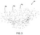
センサ32は、電場内に配置された場合、パッチ電極38間での場所と、組織に対するセンサ32の位置とに依存する電圧を受ける。センサ32およびパッチ電極38の間で行われる電圧測定比較を用いて、組織に対するセンサ32の場所を決定することができる。したがって、特定の関心のある領域または表面の周辺でまたはこれに沿ってカテーテル12が掃引された場合、処理装置16は、センサ32における電圧レベルの変化を反映するセンサ32から信号(場所情報)、および非導通のパッチ電極38からの信号(場所情報)を受信する。そして、処理装置16は、様々な既知のアルゴリズムを用いて、センサ32の場所(位置および向き)を決定し、センサ32の場所、したがってモデル化される関心のある構造の表面上または内部の点に対応する場所データ点46(本明細書では「データ点46」とも呼ばれ、図3に示されている)として、処理装置16に関連付けられたまたはこれによりアクセス可能なメモリまたは記憶装置、たとえばメモリ47に記録することができる。いくつかの実施形態では、場所を場所データ点として記録する前に、処理装置16により受信された信号により表される生の場所データを処理装置16により補正して、既知のまたは今後開発される技法を用いて呼吸、心臓活動、およびその他のアーティファクトを説明することができる。さらに、カテーテル12の他の部分の場所を、内挿または外挿などによりセンサ32における測定値から推測することで、さらなる場所データ点46を生成することができる。いずれにしても、経時的に取得された場所データ点46(461、462、...、46n)が収集されると、メモリまたは記憶装置に格納される点群48(図3に最もよく示されている)が形成される。When placed in an electric field, the
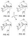
上記の説明はここまでは概してパッチ電極38の直交配置に関するものであるが、本開示はそのように限定される意図はない。むしろ、他の実施形態では、非直交配置を用いて、センサ32の場所座標を決定することができる。たとえば、大まかに言えば、図4A〜図4Dに、座標系50に設定された複数の例示的な非直交ダイポールD0、D1、D2、およびD3が示されている。図4A〜図4Dでは、X軸パッチ電極はXAおよびXBと呼ばれ、Y軸パッチ電極はYAおよびYBと呼ばれ、Z軸パッチ電極はZAおよびZBと呼ばれる。任意の所望の軸について、所定の駆動(ソース・シンク)構成の組から得られたセンサ32などの心臓内センサを介して測定された電位を代数的に結合して、直交軸に沿って均一な電流を単に駆動することで得られるのと同じ有効電位を生成することができる。パッチ電極38X1、38X2、38Y1、38Y2、38Z1、および38Z2(図2参照)のうちの任意の2つを、腹部パッチ38Bなどの接地基準に対するダイポールのソースおよびドレインとして選択することができ、非励起パッチ電極が接地基準に対する電圧を測定する。また、心臓20内に配置されたセンサ32は、電流パルスに関する場にさらされ、接地(たとえば腹部パッチ38B)に対して測定される。Although the above description has generally been directed to an orthogonal arrangement of
他の例示的実施形態では、複数のパッチ電極38を、共通の軸に沿って直線的に配列することができる。そのような実施形態では、パッチ電極38のうちの1つとカテーテル12に取り付けられた電極とを含む電極ペアを励起させると、電場が発生する。そして、非励起パッチ電極38は、センサ32の位置を決定するのに使用可能な電位を測定することができる。したがって、そのような実施形態では、異なるパッチ電極38とカテーテルに取り付けられた電極とを含む複数の電極ペアの励起を用いて、センサ32の位置を決定することができる。 In other exemplary embodiments, the plurality of
パッチ電極38の各々およびセンサ32からのデータセットは全て、心臓20内のセンサ32の場所を決定するために使用される。電圧測定が行われた後、パッチ電極38の異なるペアが電流源により励起され、残りのパッチ電極38およびセンサ32の電圧測定処理が行われる。センサ32の場所が決定されると、上記で説明されたように、場所はデータ点46として上記と同じように記録することができる。いくつかの実施形態では、場所を場所データ点として記録する前に、処理装置16により受信された信号により表される生の場所データを処理装置16により補正して、既知のまたは今後開発される技法を用いて呼吸、心臓活動、およびその他のアーティファクトを説明することができる。したがって、センサ32の場所を決定するために、したがってそれに対応するデータ点を収集するために任意数の技法を用いることができ、その各々は本開示の趣旨および範囲から逸脱しないことは理解されよう。 Each of the
図3は、モデル化される特定の関心のある構造に対応する場所データ点461、462、...46nを含む点群48を示す。実際には、点群48は数百から数十万のデータ点46を一般的に含むことは理解されよう。しかしながら、例示および説明を簡単にするために、以下の説明は、限られた数の場所データ点を有する点群、たとえば場所データ点46を含む点群48に限定される。関心のある構造の異なる領域に対応する場所データ点46を収集できることも理解されよう。そのような実施形態では、処理装置16は、それらが収集された関心のある構造の領域に対応するデータ点46をグループ化するように構成することができる。したがって、関心のある構造の2つの領域が存在する場合、第1の領域に対応する場所データ点の全てが共にグループ化され第1の点群を形成し、第2の領域に対応するデータ点の全てが共に同様にグループ化され第2の点群を形成する。FIG. 3 shows the location data points 461 , 462 ,. . . A point group 48 including 46n is shown. In practice, it will be appreciated that the point cloud 48 typically includes hundreds to hundreds of thousands of data points 46. However, for ease of illustration and description, the following description is limited to a point cloud having a limited number of location data points, eg, a point cloud 48 including location data points 46. It will also be appreciated that location data points 46 corresponding to different regions of the structure of interest can be collected. In such an embodiment, the
図5は、パッチ表面モデルを生成するための方法500のフロー図である。いくつかの実施形態では、たとえば、方法500は上述の処理装置16を用いて実施される。方法500は、(図3に示された)場所データ点46などの複数の場所データ点を取得する(502)ことを含む。場所データ点は、上述のシステムおよび方法を用いるなどして取得する(502)ことができる。 FIG. 5 is a flow diagram of a
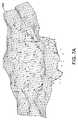
基準面が場所データ点に基づいて生成される(504)。具体的には、場所データ点により形成される点群を最も近似する基準面が生成される。いくつかの実施形態では、点群の全体形状に応じて、基準面は平面または球となる。代替として、基準面は、方法500が本明細書に記載のように機能することを可能にする任意の幾何学的形状とすることができる。一実施形態では、点群に最も適合する球が最初に選択される。選択された球の半径が大きすぎて(たとえば200ミリメートル(mm)より大きい)(後述の)細分化が非実用的になる場合(たとえば、ジオメトリおよびマップを十分に詳細に表示するのに十分小さい三角形の大きさを得るには、非常に多数の頂点および三角形が必要となるなどの理由で)、点群は代わりに平面に最も適合される。 A reference plane is generated based on the location data points (504). Specifically, a reference plane that most closely approximates a point group formed by location data points is generated. In some embodiments, the reference plane is a plane or a sphere, depending on the overall shape of the point cloud. Alternatively, the reference plane can be any geometric shape that allows the
基準面は複数の三角形に細分化される(506)。一実施形態では、基準面は複数の正三角形に細分化され(506)、各正三角形は3つの頂点を有する。正三角形の大きさは、ユーザがユーザ入力装置53(図1に図示)などを操作することによって指定することができる。正三角形が小さいほど頂点が多くなり、正三角形が大きいほど頂点が少なくなる。 The reference plane is subdivided into a plurality of triangles (506). In one embodiment, the reference plane is subdivided into a plurality of equilateral triangles (506), and each equilateral triangle has three vertices. The size of the equilateral triangle can be specified by the user operating the user input device 53 (shown in FIG. 1) or the like. The smaller the regular triangle, the more vertices, and the larger the regular triangle, the fewer vertices.
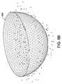
基準面が平面である場合、平面を複数の正三角形に分割することは比較的簡単である。基準面が球である場合、球を20面体(すなわち、20面を有する多面体)に間引くことができる。20面体の各面は、3つの頂点を有する正三角形である。さらに、各面は、三角形が所定の大きさに到達するまで、より小さい三角形に再帰的に分割することができる。図6Aは、(図3に示された)点群48について生成された細分化された平面基準面602を示し、図6Bは、点群48について生成された細分化された球面基準面604を示す。 When the reference plane is a plane, it is relatively easy to divide the plane into a plurality of equilateral triangles. When the reference surface is a sphere, the sphere can be thinned into a icosahedron (ie, a polyhedron having 20 surfaces). Each face of the icosahedron is an equilateral triangle having three vertices. Furthermore, each face can be recursively divided into smaller triangles until the triangles reach a predetermined size. FIG. 6A shows a refined
基準面の三角形が識別された状態で、この実施形態では、点群の各場所データ点が基準面上の最近傍点に投影される(508)。代替として、いくつかの実施形態では、場所データ点のサブセット(すなわち、全てより少ない)のみが、基準面状の最近傍点に投影される。これにより、方法500のリアルタイム性能が向上する。たとえば、一実施形態では、所定数の場所データ点(たとえば、800点)が投影される。点を決定するために、ジオメトリの3D空間全体を複数のビン(たとえばボクセル)に分割することができ、元の場所データ点のそれぞれは、それを含むビンに関連付けられる。場所データ点を含むビンの数Nがカウントされる。Nが所定数の半分未満(たとえば400点未満)である場合、ビンはより小さくされる。Nが限度より大きい場合、ビンはより大きくされる。次いで、1つのランダムな場所データ点が各ビンから選択され、選択された点が基準面に投影される。これにより、3D空間全体にわたって800点がランダムに選択された場合よりも、より均一な分布が得られる。 In this embodiment, with the reference plane triangle identified, each location data point in the point cloud is projected to the nearest point on the reference plane (508). Alternatively, in some embodiments, only a subset of location data points (i.e., less than all) is projected onto reference plane-like nearest points. This improves the real-time performance of the
投影(508)に続いて、投影された場所データ点を元の場所データ点へモーフィングする薄板スプライン関数を計算する(510)。薄板スプライン関数は、たとえば、基準面上の頂点ごとに高さ値を指定する高さ関数とすることができる。この関数を基準面に適用して、パッチ表面モデルを生成する。図7Aは、(図6Aに示された)平面基準面602から生成されたパッチ表面モデル702を示し、図7Bは、(図6Bに示された)球面基準面604から生成されたパッチ表面モデル704を示す。この実施形態では、薄板スプライン関数が使用される。代替として、任意の適切な数学関数を利用して、基準面からパッチ表面モデルを生成することができる。 Following projection (508), a thin plate spline function is computed (510) that morphs the projected location data points to the original location data points. The thin plate spline function can be, for example, a height function that specifies a height value for each vertex on the reference surface. This function is applied to the reference plane to generate a patch surface model. FIG. 7A shows a
一実施形態では、薄板スプライン関数は、投影された場所点および元の場所点が基準対として使用される3次元放射基底関数である。投影された点を元の場所点に最良にモーフィングする薄板スプライン関数が計算され、基準面の頂点ごとに変換を評価してパッチ表面モデルを生成する。 In one embodiment, the thin plate spline function is a three-dimensional radial basis function in which the projected location point and the original location point are used as a reference pair. A thin plate spline function that best morphs the projected point back to the original location point is calculated, and the transformation is evaluated for each vertex of the reference plane to generate a patch surface model.
最終的なパッチ表面モデルを生成するために、境界が決定される(512)。境界は、様々な技法を用いて決定する(512)ことができる。たとえば、基準面が平面または球である場合、投影された場所データ点を含むあらゆる三角形を含めることによって境界を決定する(512)ことができる。他の例では、基準面が平面または球である場合、投影された場所データ点の全てを含むバウンディング・ボックスが定義され、三角形がバウンディング・ボックスのエッジからエロードされ、これは、投影された場所データ点を含む三角形はエロードできず、エロードが60°の角度(すなわち、突き出たまたは窪んだ、孤立した三角形)を生成できないという条件で行われる。これらの条件によって、比較的滑らかな境界を決定する(512)ことが容易になる。代替として、任意の適切なエロードアルゴリズムを用いて、境界を決定する(512)ことができる。 In order to generate a final patch surface model, boundaries are determined (512). The boundary can be determined 512 using various techniques. For example, if the reference plane is a plane or sphere, the boundary can be determined 512 by including any triangles that contain projected location data points. In another example, if the reference plane is a plane or sphere, a bounding box is defined that includes all of the projected location data points, and a triangle is loaded from the bounding box edge, which is the projected location Triangles containing data points cannot be loaded, provided that the erode cannot produce a 60 ° angle (ie, an isolated triangle that is protruding or depressed). These conditions facilitate determining (512) a relatively smooth boundary. Alternatively, the boundary can be determined 512 using any suitable eload algorithm.
さらに他の例では、基準面が平面である場合、正三角形の辺に平行な線を生成し(これにより6つの異なる向きの線が生成される)、投影された場所データ点の全てを含む線によって形成される最小の六角形として境界を決定する(512)ことによって、境界を決定する(512)ことができる。 In yet another example, if the reference plane is a plane, it generates a line parallel to the sides of the equilateral triangle (which creates a line with six different orientations) and includes all of the projected location data points The boundary can be determined (512) by determining (512) the smallest hexagon formed by the line.
他の例では、基準面の外側境界を一回りし、外側境界の頂点ごとに、最も近い元の場所データ点を発見することによって境界が決定される(512)。2つの後続の外側境界の頂点についての最も近い元の場所データ点が異なる場合、これらを接続してエッジを形成する。外側境界全体が一回りされると、(単一の閉曲線を形成する)エッジがパッチ表面モデルに投影され、単一の閉曲線の外側の全ての三角形および部分三角形がトリミングされる。この方法は比較的頑健であるが、面が空洞または分離した構成要素を含む場合に失敗することがある。 In another example, the boundary is determined by going around the outer boundary of the reference plane and finding the nearest original location data point for each vertex of the outer boundary (512). If the nearest original location data points for the two subsequent outer boundary vertices are different, they are connected to form an edge. Once the entire outer boundary has been circled, the edges (forming a single closed curve) are projected onto the patch surface model and all triangles and partial triangles outside the single closed curve are trimmed. This method is relatively robust, but may fail if the surface contains cavities or separate components.
他の例では、「ボール・ピボット(ball pivoting)」(たとえば、Bernardini,F.ら、1999年、「The ball−pivoting algorithm for surface reconstruction」、IEEE Transactions on Visualization and Computer Graphics 5(4)、349−359頁を参照されたい)と類似した方法を用いて表面境界が決定される(512)。この例では、既知の外部の場所データ点から開始して、所定の半径と、パッチ表面モデルに垂直な(または、外部の点および外部境界の間のベクトル、もしくは2つのベクトルの何らかの線形結合などに垂直な)軸とを有する、データ点に接する円筒が作成される。半径は、境界の決定の粗さまたは細かさを決定する。次いで、円筒は表面の周りを反時計回りの方向に「回転」され、接触した連続する各場所データ点を表面に投影し、前の例と同様に、これをトリミングされる閉境界曲線の一部とする。この方法は、空洞および複数の構成要素を扱うことができるが、前の例ほど頑健ではなく、表面が滑らかでない(法線ベクトルをあまりに急激に変化させる)場合に失敗することがある。 Other examples include "ball pivoting" (e.g., Bernardini, F. et al., 1999, "The ball-pivoting algorithm for surface reconduction 5", IEEE Transaction 5). The surface boundary is determined using a method similar to (see page -359) (512). In this example, starting from a known external location data point, a given radius and perpendicular to the patch surface model (or a vector between the external point and the external boundary, or some linear combination of two vectors, etc.) A cylinder is created that touches the data point with an axis (perpendicular to). The radius determines the roughness or fineness of the boundary determination. The cylinder is then “rotated” around the surface in a counterclockwise direction, projecting each successive location data point that touches it onto the surface, which, like the previous example, is one of the closed boundary curves being trimmed. Part. This method can handle cavities and multiple components, but is not as robust as the previous example and may fail if the surface is not smooth (changes the normal vector too rapidly).
さらに他の例では、ユーザは、トリミングされるパッチ・ジオメトリ表面の周辺に残留するための所定の「ボーダー距離」を指定することができる。「ボーダー距離」は、グラフィカル・ユーザ・インターフェース(GUI)に表示されたスライダを用いるなどして調整することができる。デフォルトでは、上記の手順は、元の場所データ点の周辺にボーダーを残さない(すなわち、ゼロ距離)。しかしながら、境界エッジリスト内の各点は、ユーザ指定されたボーダー距離だけパッチ・ジオメトリ表面に沿って外側に、その近傍のエッジの平均法線の方向に単純に移動させることができる。次いで、移動された点は、トリミング用の新たな境界エッジリストとして使用することができる。なお、三角形の元の「基準面」は、少なくともボーダー距離で元の場所データ点を含むのに十分大きくなければならない。この技法は、本明細書に記載の表面境界決定方法のいずれとも併用することができる。 In yet another example, the user can specify a predetermined “border distance” to remain around the patch geometry surface to be trimmed. The “border distance” can be adjusted by using a slider displayed on a graphical user interface (GUI). By default, the above procedure does not leave a border around the original location data point (ie, zero distance). However, each point in the boundary edge list can simply be moved outward along the patch geometry surface by a user-specified border distance in the direction of the average normal of its neighboring edges. The moved point can then be used as a new boundary edge list for trimming. Note that the original “reference plane” of the triangle must be large enough to include the original location data point at least at the border distance. This technique can be used in conjunction with any of the surface boundary determination methods described herein.
境界が決定される(512)と、最終的なパッチ表面モデルが完成する。最終的なパッチ表面モデルは、(図1に示された)表示装置44などに表示することができる。当業者には理解されるように、診断ランドマーク・マップ(diagnostic landmark map)(すなわち、異なる色での所与の特性についての異なるスカラー値を示すマップ)、テープ・メジャー、ラベル、傷(lesion)、カットアウト、および/または他のマーカを、最終的なパッチ表面モデル上に配置し描画することができる。もちろん、最終的なパッチ表面モデルは必ずしも閉じていないので、いくつかのオブジェクト(たとえば、マーカおよびカットアウト)を適宜修正する必要がある場合がある。 Once the boundary is determined (512), the final patch surface model is complete. The final patch surface model can be displayed on a display device 44 (shown in FIG. 1) or the like. As will be appreciated by those skilled in the art, a diagnostic landmark map (ie, a map showing different scalar values for a given property in different colors), tape measure, label, scratch ), Cutouts, and / or other markers can be placed and rendered on the final patch surface model. Of course, the final patch surface model is not necessarily closed, so some objects (eg, markers and cutouts) may need to be modified accordingly.
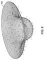
いくつかの実施形態では、最終的なパッチ表面モデルの「平滑性」を選択的に調整することができる。具体的には、ユーザは、(たとえば表示装置44に表示されたスライダを操作することによって)平滑係数を調整することができる。最大平滑係数について、計算された薄板スプライン係数は、曲がりまたは反りなしで基準面を生成する。対照的に、最小平滑係数について、計算された薄板スプライン係数は、場所データ点の全てを通過するパッチ表面モデルを生成し、その結果、パッチ表面モデルが比較的急峻でギザギザになり得る。例示のために、図7Bに、比較的低い平滑係数を選択して生成したパッチ表面モデル704を示し、図8に、比較的高い平滑係数を選択して生成したパッチ表面モデル802を示す。図7Bおよび図8に示されるように、パッチ表面モデル802に比べて、パッチ表面モデル704上により多くの表面特徴が定義されている。さらに、図7Bおよび図8に示されるように、パッチ表面モデル704および802の両方は開曲面モデルである。他の実施形態では、生成されるパッチ表面モデルは閉曲面とすることができる。 In some embodiments, the “smoothness” of the final patch surface model can be selectively adjusted. Specifically, the user can adjust the smoothing coefficient (for example, by operating a slider displayed on the display device 44). For the maximum smoothing factor, the calculated thin plate spline factor produces a reference surface without bending or warping. In contrast, for the minimum smoothing factor, the calculated thin plate spline coefficients produce a patch surface model that passes through all of the location data points, so that the patch surface model can be relatively steep and jagged. For illustration, FIG. 7B shows a
上述のモデル構築システム14、特に処理装置16は、全てが本明細書に記載の機能に従って作動する、関連付けられたメモリに格納された事前にプログラムされた命令を実行可能な、当技術分野で知られている従来の処理装置を含むことができることは理解されたい。本発明の実施形態の方法ステップを限定なしで含む、本明細書に記載の方法が、いくつかの実施形態でプログラムされ、結果のソフトウェアが関連付けられたメモリに格納され、またそのように記載された場合、そのような方法を実行するための手段を構成することもできることが企図されている。前述の実施可能な程度の記載を考慮したソフトウェアでの本発明の実装は、当業者によるプログラミング技術の日常的な使用を求めるにすぎない。さらにそのようなシステムは、ソフトウェアを格納することができ、なおかつ動的に生成されたデータおよび/または信号を格納および処理できるように、ROM、RAMの両方、不揮発性および揮発性(修正可能)メモリの組み合わせを有する種類のものとすることができる。 The
本開示の特定の実施形態がある程度詳細に上記で説明されているが、当業者であれば、本開示の趣旨または範囲から逸脱することなく、開示の実施形態の多数の変形を行うことができる。全ての方向に関する言及(たとえば、上部、下部、上方、下方、左、右、左方、右方、頂部、底部、上、下、垂直、水平、時計回り、および反時計回り)は、読者が本開示を理解するのを支援するための識別のためのものにすぎず、特に本開示の位置、向き、または使用について限定するものではない。結合に関する言及(たとえば、添付される、結合される、接続される、など)は、広く解釈されるべきであり、要素の接続間の中間部材、および要素間の相対移動を含むことができる。したがって、結合に関する言及は必ずしも、2つの要素が直接接続されており、互いに固定された関係にあることを暗示するものではない。上記の記載に含まれたまたは添付の図面に示された全ての事項が、単なる例示として解釈され、限定として解釈されないものであることが意図されている。細部または構造の変更は、添付の特許請求の範囲で定義された本開示の趣旨から逸脱することなく行うことができる。 While particular embodiments of the present disclosure have been described above in some detail, a person skilled in the art can make many variations of the disclosed embodiments without departing from the spirit or scope of the present disclosure. . References to all directions (eg, top, bottom, top, bottom, left, right, left, right, top, bottom, top, bottom, vertical, horizontal, clockwise, and counterclockwise) It is merely for identification purposes to assist in understanding the present disclosure and does not specifically limit the position, orientation, or use of the present disclosure. References to coupling (eg, attached, coupled, connected, etc.) are to be interpreted broadly and can include intermediate members between the connections of the elements and relative movement between the elements. Thus, references to coupling do not necessarily imply that the two elements are directly connected and in a fixed relationship with each other. It is intended that all matter contained in the above description or shown in the accompanying drawings shall be interpreted as illustrative only and not as limiting. Changes in detail or structure may be made without departing from the spirit of the present disclosure as defined in the appended claims.
本開示またはその好適な実施形態の要素を紹介する際に、冠詞「a」、「an」、「the」、および「said」は、その要素の1つまたは複数が存在することを意味するものとする。「comprising(備える)」、「including(含む)」、および「having(有する)」という用語は、包括的であるものとし、列挙された要素以外の追加要素が存在し得ることを意味する。 In introducing elements of this disclosure or its preferred embodiments, the articles “a”, “an”, “the”, and “said” mean that one or more of the elements are present. And The terms “comprising”, “including”, and “having” are intended to be inclusive and mean that there may be additional elements other than the listed elements.
本開示の範囲から逸脱することなく上記の構成に様々な変更を行うことができるので、上記の説明に含まれるまたは添付の図面に示された全ての事項が、例示的なものとして限定的な意味でなく解釈されるべきであることが意図されている。
以下の項目は、国際出願時の特許請求の範囲に記載の要素である。
[項目1]
幾何学的構造のパッチ表面モデルを生成するためのシステムであって、
前記幾何学的構造の表面上のそれぞれの場所に対応する元の場所データ点のセットを取得するように構成された少なくとも1つのセンサを含む装置に結合されるように構成されたコンピュータ・ベースのモデル構築システムを備え、前記コンピュータ・ベースのモデル構築システムは、
取得された前記元の場所データ点に基づいて基準面を生成し、
前記基準面を複数の三角形に細分化し、
前記元の場所データ点の少なくとも一部を細分化された前記基準面上のそれぞれの最近傍点に投影し、
投影された前記場所データ点を前記元の場所データ点にモーフィングする関数を計算してパッチ表面モデルを生成し、
前記パッチ表面モデルの境界を決定する
ようにさらに構成された、システム。
[項目2]
前記基準面は平面および球のうち1つである、項目1に記載のシステム。
[項目3]
関数を計算するために、前記コンピュータ・ベースのモデル構築システムは、薄板スプライン関数を計算するように構成された、項目1に記載のシステム。
[項目4]
前記パッチ表面モデルの境界を決定するために、前記コンピュータ・ベースのモデル構築システムは、
前記パッチ表面モデル上の外側境界の頂点ごとに、最も近い元の場所データ点を決定し、
連続する最も近い元の場所データ点の間にエッジを描いて閉曲線を形成し、
前記閉曲線を前記パッチ表面モデルに投影し、
投影された前記閉曲線の外側の三角形および部分三角形をトリミングする
ように構成された、項目3に記載のシステム。
[項目5]
前記パッチ表面モデルの境界を決定するために、前記コンピュータ・ベースのモデル構築システムは、
バウンディング・ボックスを定義し、
前記バウンディング・ボックスのエッジから複数の正三角形の一部をエロードする
ように構成された、項目3に記載のシステム。
[項目6]
関数を計算するために、前記コンピュータ・ベースのモデル構築システムは、開曲面モデルであるパッチ表面モデルを生成する関数を計算するように構成された、項目1に記載のシステム。
[項目7]
関数を計算するために、前記コンピュータ・ベースのモデル構築システムは、ユーザにより選択される平滑係数に基づいて関数を計算するように構成された、項目1に記載のシステム。
[項目8]
幾何学的構造のパッチ表面モデルを生成する、コンピュータで実施される方法であって、
前記幾何学的構造の表面上のそれぞれの場所に対応する元の場所データ点のセットを受信することと、
取得された前記元の場所データ点に基づいて基準面を生成することと、
前記基準面を複数の三角形に細分化することと、
前記元の場所データ点の少なくとも一部を細分化された前記基準面上のそれぞれの最近傍点に投影することと、
投影された前記場所データ点を前記元の場所データ点にモーフィングする関数を計算してパッチ表面モデルを生成することと、
前記パッチ表面モデルの境界を決定することと、
を備える方法。
[項目9]
基準面を生成することは、平面および球のうち1つを生成することを備える、項目8に記載の方法。
[項目10]
前記基準面を複数の三角形に細分化することは、前記基準面を複数の正三角形に細分化することを備える、項目8に記載の方法。
[項目11]
前記パッチ表面モデルの境界を決定することは、
前記パッチ表面モデル上の外側境界の頂点ごとに、最も近い元の場所データ点を決定することと、
連続する最も近い元の場所データ点の間にエッジを描いて閉曲線を形成することと、
前記閉曲線を前記パッチ表面モデルに投影することと、
投影された前記閉曲線の外側の三角形および部分三角形をトリミングすることとを備える、項目10に記載の方法。
[項目12]
前記パッチ表面モデルの境界を決定することは、
バウンディング・ボックスを定義することと、
前記バウンディング・ボックスのエッジから前記複数の正三角形の一部をエロードすることと
を備える、項目10に記載の方法。
[項目13]
前記パッチ表面モデルの境界を決定することは、ユーザ指定されたボーダー距離に基づいて境界を決定することを備える、項目8に記載の方法。
[項目14]
関数を計算することは、ユーザにより選択される平滑係数に基づいて計算することを備える、項目8に記載の方法。
[項目15]
幾何学的構造のパッチ表面モデルを生成するための処理装置であって、
前記幾何学的構造の表面上のそれぞれの場所に対応する元の場所データ点のセットを受信し、
取得された前記元の場所データ点に基づいて基準面を生成し、
前記基準面を複数の三角形に細分化し、
前記元の場所データ点の少なくとも一部を細分化された前記基準面上のそれぞれの最近傍点に投影し、
投影された前記場所データ点を前記元の場所データ点にモーフィングする関数を計算してパッチ表面モデルを生成し、
前記パッチ表面モデルの境界を決定する
ように構成された処理装置。Since various modifications can be made to the above configuration without departing from the scope of the present disclosure, all matter contained in the above description or shown in the accompanying drawings is illustrative only and not limiting. It is intended to be interpreted rather than meaning.
The following items are the elements described in the claims at the time of international application.
[Item 1]
A system for generating a patch surface model of geometric structure,
Computer-based configured to be coupled to an apparatus including at least one sensor configured to obtain an original location data point set corresponding to each location on the surface of the geometric structure Comprising a model building system, the computer-based model building system comprising:
Generate a reference plane based on the acquired original location data points;
Subdividing the reference plane into a plurality of triangles;
Projecting at least a portion of the original location data points to respective nearest points on the subdivided reference plane;
Generating a patch surface model by calculating a function to morph the projected location data points to the original location data points;
Determine the boundary of the patch surface model
Further configured as a system.
[Item 2]
The system according to item 1, wherein the reference plane is one of a plane and a sphere.
[Item 3]
The system of item 1, wherein the computer-based model building system is configured to calculate a thin plate spline function to calculate a function.
[Item 4]
In order to determine the boundary of the patch surface model, the computer-based model building system comprises:
For each vertex of the outer boundary on the patch surface model, determine the nearest original location data point;
Draw an edge between the nearest consecutive original location data points to form a closed curve,
Projecting the closed curve onto the patch surface model;
Trim triangles and partial triangles outside the projected closed curve
4. A system according to item 3, configured as described above.
[Item 5]
In order to determine the boundary of the patch surface model, the computer-based model building system comprises:
Define the bounding box,
Erod some of the equilateral triangles from the edge of the bounding box
4. A system according to item 3, configured as described above.
[Item 6]
The system of item 1, wherein the computer-based model building system is configured to calculate a function that generates a patch surface model that is an open surface model to calculate a function.
[Item 7]
The system of claim 1, wherein to calculate a function, the computer-based model building system is configured to calculate a function based on a smoothing factor selected by a user.
[Item 8]
A computer-implemented method for generating a geometric patch surface model comprising:
Receiving a set of original location data points corresponding to each location on the surface of the geometric structure;
Generating a reference plane based on the acquired original location data points;
Subdividing the reference plane into a plurality of triangles;
Projecting at least a portion of the original location data points to respective nearest points on the subdivided reference plane;
Generating a patch surface model by calculating a function that morphs the projected location data points to the original location data points;
Determining boundaries of the patch surface model;
A method comprising:
[Item 9]
The method of item 8, wherein generating the reference plane comprises generating one of a plane and a sphere.
[Item 10]
9. The method of item 8, wherein subdividing the reference plane into a plurality of triangles comprises subdividing the reference plane into a plurality of equilateral triangles.
[Item 11]
Determining the boundary of the patch surface model is
Determining the closest original location data point for each vertex of the outer boundary on the patch surface model;
Drawing an edge between successive successive original location data points to form a closed curve;
Projecting the closed curve onto the patch surface model;
12. Trimming triangles and partial triangles outside the projected closed curve.
[Item 12]
Determining the boundary of the patch surface model is
Defining a bounding box;
Eroding a portion of the equilateral triangles from an edge of the bounding box;
A method according to
[Item 13]
9. The method of item 8, wherein determining a boundary of the patch surface model comprises determining a boundary based on a user-specified border distance.
[Item 14]
Item 9. The method of item 8, wherein calculating the function comprises calculating based on a smoothing factor selected by a user.
[Item 15]
A processing device for generating a patch surface model of geometric structure, comprising:
Receiving a set of original location data points corresponding to each location on the surface of the geometric structure;
Generate a reference plane based on the acquired original location data points;
Subdividing the reference plane into a plurality of triangles;
Projecting at least a portion of the original location data points to respective nearest points on the subdivided reference plane;
Generating a patch surface model by calculating a function to morph the projected location data points to the original location data points;
Determine the boundary of the patch surface model
A processing apparatus configured as described above.
Claims (15)
Translated fromJapanese前記幾何学的構造の表面上のそれぞれの場所に対応する元の場所データ点のセットを取得するように構成された少なくとも1つのセンサを含む装置に結合されるように構成されたコンピュータ・ベースのモデル構築システムを備え、前記コンピュータ・ベースのモデル構築システムは、
取得された前記元の場所データ点に基づいて基準面を生成し、
前記基準面を複数の三角形に細分化し、
前記元の場所データ点の少なくとも一部を細分化された前記基準面上のそれぞれの最近傍点に投影し、
投影された前記場所データ点を前記元の場所データ点にモーフィングする関数を計算してパッチ表面モデルを生成し、
前記パッチ表面モデルの境界を決定する
ようにさらに構成された、システム。A system for generating a patch surface model of geometric structure,
Computer-based configured to be coupled to an apparatus including at least one sensor configured to obtain an original location data point set corresponding to each location on the surface of the geometric structure Comprising a model building system, the computer-based model building system comprising:
Generate a reference plane based on the acquired original location data points;
Subdividing the reference plane into a plurality of triangles;
Projecting at least a portion of the original location data points to respective nearest points on the subdivided reference plane;
Generating a patch surface model by calculating a function to morph the projected location data points to the original location data points;
A system further configured to determine a boundary of the patch surface model.
前記パッチ表面モデル上の外側境界の頂点ごとに、最も近い元の場所データ点を決定し、
連続する最も近い元の場所データ点の間にエッジを描いて閉曲線を形成し、
前記閉曲線を前記パッチ表面モデルに投影し、
投影された前記閉曲線の外側の三角形および部分三角形をトリミングする
ように構成された、請求項3に記載のシステム。In order to determine the boundary of the patch surface model, the computer-based model building system comprises:
For each vertex of the outer boundary on the patch surface model, determine the nearest original location data point;
Draw an edge between the nearest consecutive original location data points to form a closed curve,
Projecting the closed curve onto the patch surface model;
The system of claim 3, configured to trim triangles and partial triangles outside the projected closed curve.
バウンディング・ボックスを定義し、
前記バウンディング・ボックスのエッジから複数の正三角形の一部をエロードする
ように構成された、請求項3に記載のシステム。In order to determine the boundary of the patch surface model, the computer-based model building system comprises:
Define the bounding box,
The system of claim 3, wherein the system is configured to load a portion of a plurality of equilateral triangles from an edge of the bounding box.
前記幾何学的構造の表面上のそれぞれの場所に対応する元の場所データ点のセットを受信することと、
取得された前記元の場所データ点に基づいて基準面を生成することと、
前記基準面を複数の三角形に細分化することと、
前記元の場所データ点の少なくとも一部を細分化された前記基準面上のそれぞれの最近傍点に投影することと、
投影された前記場所データ点を前記元の場所データ点にモーフィングする関数を計算してパッチ表面モデルを生成することと、
前記パッチ表面モデルの境界を決定することと、
を備える方法。A computer-implemented method for generating a geometric patch surface model comprising:
Receiving a set of original location data points corresponding to each location on the surface of the geometric structure;
Generating a reference plane based on the acquired original location data points;
Subdividing the reference plane into a plurality of triangles;
Projecting at least a portion of the original location data points to respective nearest points on the subdivided reference plane;
Generating a patch surface model by calculating a function that morphs the projected location data points to the original location data points;
Determining boundaries of the patch surface model;
A method comprising:
前記パッチ表面モデル上の外側境界の頂点ごとに、最も近い元の場所データ点を決定することと、
連続する最も近い元の場所データ点の間にエッジを描いて閉曲線を形成することと、
前記閉曲線を前記パッチ表面モデルに投影することと、
投影された前記閉曲線の外側の三角形および部分三角形をトリミングすることとを備える、請求項10に記載の方法。Determining the boundary of the patch surface model is
Determining the closest original location data point for each vertex of the outer boundary on the patch surface model;
Drawing an edge between successive successive original location data points to form a closed curve;
Projecting the closed curve onto the patch surface model;
11. Trimming triangles and partial triangles outside the projected closed curve.
バウンディング・ボックスを定義することと、
前記バウンディング・ボックスのエッジから前記複数の正三角形の一部をエロードすることと
を備える、請求項10に記載の方法。Determining the boundary of the patch surface model is
Defining a bounding box;
The method of claim 10, comprising: loading a portion of the plurality of equilateral triangles from an edge of the bounding box.
前記幾何学的構造の表面上のそれぞれの場所に対応する元の場所データ点のセットを受信し、
取得された前記元の場所データ点に基づいて基準面を生成し、
前記基準面を複数の三角形に細分化し、
前記元の場所データ点の少なくとも一部を細分化された前記基準面上のそれぞれの最近傍点に投影し、
投影された前記場所データ点を前記元の場所データ点にモーフィングする関数を計算してパッチ表面モデルを生成し、
前記パッチ表面モデルの境界を決定する
ように構成された処理装置。A processing device for generating a patch surface model of geometric structure, comprising:
Receiving a set of original location data points corresponding to each location on the surface of the geometric structure;
Generate a reference plane based on the acquired original location data points;
Subdividing the reference plane into a plurality of triangles;
Projecting at least a portion of the original location data points to respective nearest points on the subdivided reference plane;
Generating a patch surface model by calculating a function to morph the projected location data points to the original location data points;
A processing apparatus configured to determine a boundary of the patch surface model.
Applications Claiming Priority (3)
| Application Number | Priority Date | Filing Date | Title |
|---|---|---|---|
| US201462081089P | 2014-11-18 | 2014-11-18 | |
| US62/081,089 | 2014-11-18 | ||
| PCT/US2015/056441WO2016081130A1 (en) | 2014-11-18 | 2015-10-20 | Method and system for generating a patch surface model of a geometric structure |
Publications (2)
| Publication Number | Publication Date |
|---|---|
| JP2018501549A JP2018501549A (en) | 2018-01-18 |
| JP6423964B2true JP6423964B2 (en) | 2018-11-14 |
Family
ID=54397003
Family Applications (1)
| Application Number | Title | Priority Date | Filing Date |
|---|---|---|---|
| JP2017526064AActiveJP6423964B2 (en) | 2014-11-18 | 2015-10-20 | Method and system for generating geometric patch surface models |
Country Status (5)
| Country | Link |
|---|---|
| US (2) | US9947142B2 (en) |
| EP (1) | EP3180775B1 (en) |
| JP (1) | JP6423964B2 (en) |
| CN (1) | CN107111891B (en) |
| WO (1) | WO2016081130A1 (en) |
Families Citing this family (21)
| Publication number | Priority date | Publication date | Assignee | Title |
|---|---|---|---|---|
| US11567201B2 (en) | 2016-03-11 | 2023-01-31 | Kaarta, Inc. | Laser scanner with real-time, online ego-motion estimation |
| EP3427008B1 (en) | 2016-03-11 | 2022-09-07 | Kaarta, Inc. | Laser scanner with real-time, online ego-motion estimation |
| US11573325B2 (en) | 2016-03-11 | 2023-02-07 | Kaarta, Inc. | Systems and methods for improvements in scanning and mapping |
| US10989542B2 (en) | 2016-03-11 | 2021-04-27 | Kaarta, Inc. | Aligning measured signal data with slam localization data and uses thereof |
| WO2019099605A1 (en) | 2017-11-17 | 2019-05-23 | Kaarta, Inc. | Methods and systems for geo-referencing mapping systems |
| WO2019165194A1 (en)* | 2018-02-23 | 2019-08-29 | Kaarta, Inc. | Methods and systems for processing and colorizing point clouds and meshes |
| WO2019195270A1 (en) | 2018-04-03 | 2019-10-10 | Kaarta, Inc. | Methods and systems for real or near real-time point cloud map data confidence evaluation |
| US11259871B2 (en) | 2018-04-26 | 2022-03-01 | Vektor Medical, Inc. | Identify ablation pattern for use in an ablation |
| US11564641B2 (en) | 2018-04-26 | 2023-01-31 | Vektor Medical, Inc. | Generating simulated anatomies of an electromagnetic source |
| WO2020009826A1 (en) | 2018-07-05 | 2020-01-09 | Kaarta, Inc. | Methods and systems for auto-leveling of point clouds and 3d models |
| EP3880105B8 (en) | 2018-11-13 | 2025-08-27 | The Vektor Group, Inc. | Augmentation of images with source locations |
| CN109580649B (en)* | 2018-12-18 | 2020-11-27 | 清华大学 | A method and system for identification and projection correction of surface cracks in engineering structures |
| US10595736B1 (en) | 2019-06-10 | 2020-03-24 | Vektor Medical, Inc. | Heart graphic display system |
| US10709347B1 (en) | 2019-06-10 | 2020-07-14 | Vektor Medical, Inc. | Heart graphic display system |
| EP3866107A1 (en)* | 2020-02-14 | 2021-08-18 | Koninklijke Philips N.V. | Model-based image segmentation |
| US11315329B1 (en)* | 2020-02-25 | 2022-04-26 | Facebook Technologies, Llc. | Scene reconstruction from sparse data |
| US11113899B1 (en)* | 2020-08-31 | 2021-09-07 | Biosense Webster (Israel) Ltd. | Correcting anatomical maps |
| CN118103924A (en) | 2021-08-09 | 2024-05-28 | 维克多医疗股份有限公司 | Organization status graphic display system |
| US11534224B1 (en) | 2021-12-02 | 2022-12-27 | Vektor Medical, Inc. | Interactive ablation workflow system |
| WO2023107932A1 (en) | 2021-12-06 | 2023-06-15 | Snap Inc. | 3d models for augmented reality (ar) |
| US12045938B2 (en)* | 2022-08-16 | 2024-07-23 | Biosense Webster (Israel) Ltd. | Anatomical modeling with the ball-pivoting algorithm |
Family Cites Families (39)
| Publication number | Priority date | Publication date | Assignee | Title |
|---|---|---|---|---|
| US5546327A (en)* | 1990-12-27 | 1996-08-13 | Matsushita Electric Industrial Co., Ltd. | Apparatus for calculating geometrical view factor |
| US5601084A (en)* | 1993-06-23 | 1997-02-11 | University Of Washington | Determining cardiac wall thickness and motion by imaging and three-dimensional modeling |
| US6690963B2 (en) | 1995-01-24 | 2004-02-10 | Biosense, Inc. | System for determining the location and orientation of an invasive medical instrument |
| EP0973440B1 (en) | 1998-01-22 | 2006-08-02 | Biosense Webster, Inc. | Intrabody measurement |
| US7263397B2 (en) | 1998-06-30 | 2007-08-28 | St. Jude Medical, Atrial Fibrillation Division, Inc. | Method and apparatus for catheter navigation and location and mapping in the heart |
| US6591004B1 (en)* | 1998-09-21 | 2003-07-08 | Washington University | Sure-fit: an automated method for modeling the shape of cerebral cortex and other complex structures using customized filters and transformations |
| US6535213B1 (en)* | 1998-09-22 | 2003-03-18 | Sony Corporation | Curve edition system, curve-loop detecting system, curve-loop removing system |
| US7212197B1 (en)* | 1999-02-01 | 2007-05-01 | California Institute Of Technology | Three dimensional surface drawing controlled by hand motion |
| US6369815B1 (en) | 1999-04-23 | 2002-04-09 | Spatial Technology, Inc. | Deformable modeling using generalized curve constraints |
| US6233476B1 (en) | 1999-05-18 | 2001-05-15 | Mediguide Ltd. | Medical positioning system |
| US7386339B2 (en) | 1999-05-18 | 2008-06-10 | Mediguide Ltd. | Medical imaging and navigation system |
| US6545676B1 (en)* | 1999-05-24 | 2003-04-08 | Parametric Technology Corporation | Method and system for creating a tessellated approximation of an outer envelope of a complex model |
| US6941251B1 (en) | 1999-12-27 | 2005-09-06 | Spatial Corp. | Method for transforming CAD model using general function composition mechanism |
| US7023432B2 (en)* | 2001-09-24 | 2006-04-04 | Geomagic, Inc. | Methods, apparatus and computer program products that reconstruct surfaces from data point sets |
| US7697972B2 (en)* | 2002-11-19 | 2010-04-13 | Medtronic Navigation, Inc. | Navigation system for cardiac therapies |
| US20050140670A1 (en)* | 2003-11-20 | 2005-06-30 | Hong Wu | Photogrammetric reconstruction of free-form objects with curvilinear structures |
| US7974674B2 (en)* | 2004-05-28 | 2011-07-05 | St. Jude Medical, Atrial Fibrillation Division, Inc. | Robotic surgical system and method for surface modeling |
| US7197354B2 (en) | 2004-06-21 | 2007-03-27 | Mediguide Ltd. | System for determining the position and orientation of a catheter |
| US7936352B2 (en) | 2004-07-21 | 2011-05-03 | Dassault Systemes Solidworks Corporation | Deformation of a computer-generated model |
| US7358969B2 (en)* | 2004-09-27 | 2008-04-15 | International Business Machines Corporation | Method and system for partitioning the surface of a three dimentional digital object model in order to map a texture |
| JP4392507B2 (en)* | 2006-11-08 | 2010-01-06 | 国立大学法人東京工業大学 | 3D surface generation method |
| US8169435B2 (en)* | 2007-12-06 | 2012-05-01 | Esko Ip Nv | Generating and rendering three dimensional models of flexible packaging |
| US8269770B1 (en)* | 2008-02-29 | 2012-09-18 | Adobe Systems Incorporated | Tessellation of trimmed parametric surfaces by walking the surface |
| JP2010186288A (en)* | 2009-02-12 | 2010-08-26 | Seiko Epson Corp | Image processing for changing predetermined texture characteristic amount of face image |
| US20130124148A1 (en) | 2009-08-21 | 2013-05-16 | Hailin Jin | System and Method for Generating Editable Constraints for Image-based Models |
| JP4998905B2 (en)* | 2010-04-14 | 2012-08-15 | Necシステムテクノロジー株式会社 | 3D terrain data high accuracy apparatus, 3D terrain data high accuracy method and program |
| US8665266B2 (en)* | 2010-06-23 | 2014-03-04 | The United States Of America, As Represented By The Secretary Of The Navy | Global visualization process terrain database builder |
| EP2468212B1 (en)* | 2010-08-31 | 2015-01-21 | Straumann Holding AG | Computer-implemented method for digitally designing a dental restoration |
| CN103238170B (en)* | 2010-12-02 | 2015-11-25 | Dipro株式会社 | Display processing method and device |
| GB201104312D0 (en)* | 2011-03-14 | 2011-04-27 | Bell Alexandra | Improved virtual try on simulation service |
| US8909502B2 (en)* | 2011-12-29 | 2014-12-09 | St. Jude Medical, Atrial Fibrillation Division, Inc. | Method and system for constructing an electrophysiology map |
| JP5801209B2 (en)* | 2012-01-06 | 2015-10-28 | Kddi株式会社 | Camera posture estimation device, program |
| EP2876607B1 (en)* | 2012-07-23 | 2019-07-31 | Fujitsu Limited | Shape data generation method and device |
| KR20140031613A (en)* | 2012-09-05 | 2014-03-13 | 삼성전자주식회사 | Apparatus and method for processing image |
| US9895079B2 (en)* | 2012-09-26 | 2018-02-20 | Biosense Webster (Israel) Ltd. | Electropotential mapping |
| US9582615B2 (en)* | 2013-01-16 | 2017-02-28 | Jostens, Inc. | Modeling using thin plate spline technology |
| JP6461916B2 (en)* | 2013-04-18 | 2019-01-30 | セント・ジュード・メディカル・エイトリアル・フィブリレーション・ディヴィジョン・インコーポレーテッド | Method of operating a system for visualizing and analyzing arrhythmias utilizing a 2D planar projection and a partially developed surface mapping process |
| US9208609B2 (en)* | 2013-07-01 | 2015-12-08 | Mitsubishi Electric Research Laboratories, Inc. | Method for fitting primitive shapes to 3D point clouds using distance fields |
| CN103985155B (en)* | 2014-05-14 | 2017-01-25 | 北京理工大学 | Scattered point cloud Delaunay triangulation curved surface reconstruction method based on mapping method |
- 2015
- 2015-10-20JPJP2017526064Apatent/JP6423964B2/enactiveActive
- 2015-10-20WOPCT/US2015/056441patent/WO2016081130A1/enactiveApplication Filing
- 2015-10-20USUS14/887,479patent/US9947142B2/enactiveActive
- 2015-10-20EPEP15790378.2Apatent/EP3180775B1/enactiveActive
- 2015-10-20CNCN201580062345.2Apatent/CN107111891B/enactiveActive
- 2018
- 2018-03-08USUS15/915,808patent/US10861246B2/enactiveActive
Also Published As
| Publication number | Publication date |
|---|---|
| US20180240282A1 (en) | 2018-08-23 |
| US9947142B2 (en) | 2018-04-17 |
| CN107111891A (en) | 2017-08-29 |
| JP2018501549A (en) | 2018-01-18 |
| US20160140757A1 (en) | 2016-05-19 |
| WO2016081130A1 (en) | 2016-05-26 |
| CN107111891B (en) | 2020-11-17 |
| US10861246B2 (en) | 2020-12-08 |
| EP3180775A1 (en) | 2017-06-21 |
| EP3180775B1 (en) | 2019-02-13 |
Similar Documents
| Publication | Publication Date | Title |
|---|---|---|
| JP6423964B2 (en) | Method and system for generating geometric patch surface models | |
| JP5823635B2 (en) | System for constructing electrophysiology map and method of operating the processing apparatus | |
| JP6750085B2 (en) | Method and system for generating a smoothed image of an elongated medical device | |
| US9282915B2 (en) | Method and system for generating and/or repairing a surface model of a geometric structure | |
| JP6223585B2 (en) | Method and system for generating a multidimensional surface model of a geometric structure | |
| JP6691963B2 (en) | Method and system for displaying electrophysiological damage | |
| JP5890537B2 (en) | Method and system for generating a multidimensional surface model of a geometric structure | |
| JP6655176B2 (en) | Method and system for generating an electrophysiological map |
Legal Events
| Date | Code | Title | Description |
|---|---|---|---|
| A977 | Report on retrieval | Free format text:JAPANESE INTERMEDIATE CODE: A971007 Effective date:20180619 | |
| A131 | Notification of reasons for refusal | Free format text:JAPANESE INTERMEDIATE CODE: A131 Effective date:20180703 | |
| TRDD | Decision of grant or rejection written | ||
| A01 | Written decision to grant a patent or to grant a registration (utility model) | Free format text:JAPANESE INTERMEDIATE CODE: A01 Effective date:20180925 | |
| A61 | First payment of annual fees (during grant procedure) | Free format text:JAPANESE INTERMEDIATE CODE: A61 Effective date:20181019 | |
| R150 | Certificate of patent or registration of utility model | Ref document number:6423964 Country of ref document:JP Free format text:JAPANESE INTERMEDIATE CODE: R150 | |
| R250 | Receipt of annual fees | Free format text:JAPANESE INTERMEDIATE CODE: R250 | |
| R250 | Receipt of annual fees | Free format text:JAPANESE INTERMEDIATE CODE: R250 | |
| R250 | Receipt of annual fees | Free format text:JAPANESE INTERMEDIATE CODE: R250 | |
| R250 | Receipt of annual fees | Free format text:JAPANESE INTERMEDIATE CODE: R250 |