JP6421393B1 - Manufacturing method of microneedle - Google Patents
Manufacturing method of microneedleDownload PDFInfo
- Publication number
- JP6421393B1 JP6421393B1JP2018517239AJP2018517239AJP6421393B1JP 6421393 B1JP6421393 B1JP 6421393B1JP 2018517239 AJP2018517239 AJP 2018517239AJP 2018517239 AJP2018517239 AJP 2018517239AJP 6421393 B1JP6421393 B1JP 6421393B1
- Authority
- JP
- Japan
- Prior art keywords
- rod
- microneedle
- polymer compound
- hole
- liquid
- Prior art date
- Legal status (The legal status is an assumption and is not a legal conclusion. Google has not performed a legal analysis and makes no representation as to the accuracy of the status listed.)
- Expired - Fee Related
Links
Images


Classifications
- A—HUMAN NECESSITIES
- A61—MEDICAL OR VETERINARY SCIENCE; HYGIENE
- A61M—DEVICES FOR INTRODUCING MEDIA INTO, OR ONTO, THE BODY; DEVICES FOR TRANSDUCING BODY MEDIA OR FOR TAKING MEDIA FROM THE BODY; DEVICES FOR PRODUCING OR ENDING SLEEP OR STUPOR
- A61M37/00—Other apparatus for introducing media into the body; Percutany, i.e. introducing medicines into the body by diffusion through the skin
- A61M37/0015—Other apparatus for introducing media into the body; Percutany, i.e. introducing medicines into the body by diffusion through the skin by using microneedles
- B—PERFORMING OPERATIONS; TRANSPORTING
- B81—MICROSTRUCTURAL TECHNOLOGY
- B81C—PROCESSES OR APPARATUS SPECIALLY ADAPTED FOR THE MANUFACTURE OR TREATMENT OF MICROSTRUCTURAL DEVICES OR SYSTEMS
- B81C1/00—Manufacture or treatment of devices or systems in or on a substrate
- B81C1/00015—Manufacture or treatment of devices or systems in or on a substrate for manufacturing microsystems
- B81C1/00023—Manufacture or treatment of devices or systems in or on a substrate for manufacturing microsystems without movable or flexible elements
- B81C1/00111—Tips, pillars, i.e. raised structures
- A—HUMAN NECESSITIES
- A61—MEDICAL OR VETERINARY SCIENCE; HYGIENE
- A61M—DEVICES FOR INTRODUCING MEDIA INTO, OR ONTO, THE BODY; DEVICES FOR TRANSDUCING BODY MEDIA OR FOR TAKING MEDIA FROM THE BODY; DEVICES FOR PRODUCING OR ENDING SLEEP OR STUPOR
- A61M37/00—Other apparatus for introducing media into the body; Percutany, i.e. introducing medicines into the body by diffusion through the skin
- A61M37/0015—Other apparatus for introducing media into the body; Percutany, i.e. introducing medicines into the body by diffusion through the skin by using microneedles
- A61M2037/003—Other apparatus for introducing media into the body; Percutany, i.e. introducing medicines into the body by diffusion through the skin by using microneedles having a lumen
- A—HUMAN NECESSITIES
- A61—MEDICAL OR VETERINARY SCIENCE; HYGIENE
- A61M—DEVICES FOR INTRODUCING MEDIA INTO, OR ONTO, THE BODY; DEVICES FOR TRANSDUCING BODY MEDIA OR FOR TAKING MEDIA FROM THE BODY; DEVICES FOR PRODUCING OR ENDING SLEEP OR STUPOR
- A61M37/00—Other apparatus for introducing media into the body; Percutany, i.e. introducing medicines into the body by diffusion through the skin
- A61M37/0015—Other apparatus for introducing media into the body; Percutany, i.e. introducing medicines into the body by diffusion through the skin by using microneedles
- A61M2037/0053—Methods for producing microneedles
- B—PERFORMING OPERATIONS; TRANSPORTING
- B81—MICROSTRUCTURAL TECHNOLOGY
- B81C—PROCESSES OR APPARATUS SPECIALLY ADAPTED FOR THE MANUFACTURE OR TREATMENT OF MICROSTRUCTURAL DEVICES OR SYSTEMS
- B81C2201/00—Manufacture or treatment of microstructural devices or systems
- B81C2201/03—Processes for manufacturing substrate-free structures
- B81C2201/034—Moulding
- B—PERFORMING OPERATIONS; TRANSPORTING
- B81—MICROSTRUCTURAL TECHNOLOGY
- B81C—PROCESSES OR APPARATUS SPECIALLY ADAPTED FOR THE MANUFACTURE OR TREATMENT OF MICROSTRUCTURAL DEVICES OR SYSTEMS
- B81C2201/00—Manufacture or treatment of microstructural devices or systems
- B81C2201/03—Processes for manufacturing substrate-free structures
- B81C2201/036—Hot embossing
Landscapes
- Engineering & Computer Science (AREA)
- Health & Medical Sciences (AREA)
- Life Sciences & Earth Sciences (AREA)
- Animal Behavior & Ethology (AREA)
- Anesthesiology (AREA)
- Biomedical Technology (AREA)
- Heart & Thoracic Surgery (AREA)
- Hematology (AREA)
- Dermatology (AREA)
- Medical Informatics (AREA)
- General Health & Medical Sciences (AREA)
- Public Health (AREA)
- Veterinary Medicine (AREA)
- Manufacturing & Machinery (AREA)
- Chemical & Material Sciences (AREA)
- Analytical Chemistry (AREA)
- Microelectronics & Electronic Packaging (AREA)
- Media Introduction/Drainage Providing Device (AREA)
Abstract
Translated fromJapaneseDescription
Translated fromJapanese本発明は、例えば生体吸収高分子材料を使用した中空タイプのマイクロニードルの製造方法に好適なものである。 The present invention is suitable for a method for producing a hollow type microneedle using, for example, a bioabsorbable polymer material.
近年、美容目的などで、生体吸収高分子などの高分子化合物を使用したマイクロニードルが広く知られている。(例えば特許文献1参照)。 In recent years, microneedles using polymer compounds such as bioabsorbable polymers are widely known for cosmetic purposes and the like. (For example, refer to Patent Document 1).
しかしながら、上述したマイクロニードルは、目的物質をそのままマイクロニードル化するため、使用可能な目的物質に制限があるため、高分子化合物を使用した中空タイプのマイクロニードルが要望されている。 However, since the above-described microneedles are converted into microneedles as they are, the usable target substances are limited, so that hollow type microneedles using a polymer compound are desired.
本発明はこのような問題を解決するためになされたもので、その目的は、高分子化合物を使用した中空タイプのマイクロニードルの製造方法を提供するものである。 The present invention has been made to solve such problems, and an object thereof is to provide a method for producing a hollow type microneedle using a polymer compound.
かかる課題を解決するため、本発明のマイクロニードルの製造方法は、 貫通孔に細い棒状部材を貫通させ、液状又は半液状の液状高分子化合物に前記棒状部材を貫通させた状態でマイクロニードルの形状を決定する成形ステップと、
前記高分子化合物を固化させる固化ステップと
前記棒状部材を引き抜く引抜ステップとを有することを特徴とする。In order to solve such a problem, the microneedle manufacturing method of the present invention includes a microneedle shape in a state where a thin rod-like member is passed through a through-hole and the rod-like member is passed through a liquid or semi-liquid liquid polymer compound. Determining the molding step;
It has the solidification step which solidifies the said high molecular compound, and the extraction step which extracts the said rod-shaped member, It is characterized by the above-mentioned.
本発明は、高分子化合物を使用した中空タイプのマイクロニードルの製造方法を実現できる。 The present invention can realize a method for producing a hollow microneedle using a polymer compound.
<第1の実施の形態>
以下、本発明を実施するための形態について図面を参照して説明する。<First Embodiment>
Hereinafter, embodiments for carrying out the present invention will be described with reference to the drawings.
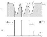
近年、美容や医療用途において、皮膚をできるだけ傷付けないように目的物質である美容成分や薬剤を皮膚に注入することを目的として、直径が小さい微小突起でなるマイクロニードルが提案されている(例えば特許第5495034号参照)。図1に示すように、このマイクロニードルP1は、金型などのモールド型P9を使用してパターンを転写することにより形成される。一般的に、マイクロニードルP1は、シート状の台座部P3に複数形成される。 In recent years, microneedles having small protrusions with a small diameter have been proposed for the purpose of injecting cosmetic ingredients and drugs as target substances into the skin so as not to damage the skin as much as possible in beauty and medical applications (for example, patents). No. 5495034). As shown in FIG. 1, the microneedle P1 is formed by transferring a pattern using a mold P9 such as a mold. Generally, a plurality of microneedles P1 are formed on a sheet-like pedestal P3.
このマイクロニードルでは、マイクロニードルそのものが目的物質を含んでおり、皮膚に刺さったマイクロニードルがそのまま体内に吸収される。しかしながら、マイクロニードルに含有させることができる目的物質の種類や量に制限がある。 In this microneedle, the microneedle itself contains the target substance, and the microneedle stabbed in the skin is absorbed into the body as it is. However, there are limitations on the types and amounts of target substances that can be contained in the microneedles.
そこで、本願発明人は、マイクロニードルに孔を形成し、当該孔を通じて目的物質を体内に注入するマイクロニードルの製造方法を見出した。 Accordingly, the inventors of the present application have found a method of manufacturing a microneedle in which a hole is formed in the microneedle and a target substance is injected into the body through the hole.
図2に示すように、本発明のマイクロニードルの製造方法では、マイクロニードルの転写パターンを有するモールド型1と、棒状部材5と、スペーサ9とが使用される。モールド型1では、マイクロニードルの転写パターンである突起用凹部2と、当該突起用凹部2に通じモールド型1の底面(突起用凹部2の対向面)へと抜ける貫通孔3を有している。この貫通孔3は、全ての突起用凹部2に対して1つずつ設けられている。モールド型1の材質に制限はなく、金属、木材及び樹脂材料など、公知の種々の材質を使用することができる。 As shown in FIG. 2, in the microneedle manufacturing method of the present invention, a mold 1 having a microneedle transfer pattern, a rod-
棒状部材5は、貫通孔3の位置に合わせて形成された複数の棒部6と、平面状の板部7とを有しており、板部7から棒部6が突出するように固着されている。板部7及び棒部6の材質に制限はなく、金属、木材及び樹脂材料など、公知の種々の材質を使用することができる。例えば棒部6は、ねじなどの留め金によって板部7に固定されている。 The rod-
スペーサ9は、棒状部材5及びモールド型1の間に挟まれることが想定されており、棒状部材5及びモールド型1の間に所定の隙間空間を形成することを目的としている。スペーサ9は、棒状部材5及びモールド型1から取り外すことができるフリー状態で存在する。 The spacer 9 is assumed to be sandwiched between the rod-
図3に示すように、まず、モールド型1に対して棒状部材5が挿入されると共に、棒状部材5及びモールド型1の間にスペーサ9が挟まれる。この結果、棒状部材5及びモールド型1の間に一定の隙間空間を残した状態で、棒状部材5がモールド型1の貫通孔3を突き抜け、モールド型1から突出する。 As shown in FIG. 3, first, the rod-
図4に示すように、棒状部材5が挿入されたモールド型1に対し、被加工物10が充填される。被加工物10は、液状又は半液状の状態で充填される。なお、液状又は半液状とは、充填時の温度における粘度が10〜30000mPa・s/60rpmであることをいい、流動性の高い液体からチキソ性の高いジェル状の状態のものを含む。そして棒状部材5が被加工物10から突き出た状態で固化される。固化の方法としては、特に制限はなく、加温されて液状化した被加工物10の冷却や、低分子の被加工物10が架橋剤や硬化剤によって化学反応(高分子化)することによる硬化、結晶化、溶媒成分の蒸発などにより被加工物10が固化される。 As shown in FIG. 4, the
固化した状態の被加工物10としては、高分子化合物を主成分とする。本明細書において、高分子化合物とは、平均分子量Mwが5000以上の有機化合物を意味する。主成分とは、被加工物における化学的骨格を担うことをいい、好ましくは高分子化合物が被加工物全体の50重量%以上である。但し、水や有機溶剤など、平均分子量Mwが300未満の溶媒成分は全体重量に含めない。例えば、ヒアルロン酸ナトリウムやコラーゲン、セルロースなどのように、水分子など特定の分子(溶媒成分)を抱き込む性質がある場合、これらの溶媒成分を全体重量に含めないものとする。高分子化合物としては、Tg(ガラス転移点)が50℃以上、より好ましくは70℃以上であることが好ましい。Tgが低いと、常温での取り扱いがしづらくなるからである。 The
高分子化合物としては、1種類のみ含有しても良く、2種類以上混合しても良い。なお、この主成分の割合は、被加工物の全加工工程終了後の重量であり、微少突起の形成後の乾燥工程で意図して蒸発させる、いわゆる溶媒成分を含まない。すなわち、被加工物の加工終了後における割合である。 As a high molecular compound, only 1 type may be contained and 2 or more types may be mixed. The ratio of the main component is the weight after completion of all the processing steps of the workpiece, and does not include a so-called solvent component that is intentionally evaporated in the drying step after the formation of the minute protrusions. That is, the ratio after the processing of the workpiece is completed.
高分子化合物としては、既知の化合物(合成高分子及び天然高分子)を使用することができる。例えばPET(ポリエチレンテレフタレート)や、ポリエチレン、ポリプロピレン、アクリル樹脂、エポキシ樹脂、ポリスチレンなど、種々のプラスチック材料の他、生体吸収高分子を使用することができる。 Known compounds (synthetic polymers and natural polymers) can be used as the polymer compound. For example, in addition to various plastic materials such as PET (polyethylene terephthalate), polyethylene, polypropylene, acrylic resin, epoxy resin, and polystyrene, bioabsorbable polymers can be used.
生体吸収高分子としては、既知の化合物(合成高分子及び天然高分子)を使用することができる。例えば、ポリ乳酸、ポリグリコール酸、ポリ−εカプロラクトン、ポリ−ρ−ジオキサン、ポリリンゴ酸などのエステル化合物、ポリ酸無水物などの酸無水物、ポリオルソエステルなどのオルソエステル化合物、ポリカーボネートなどのカーボネート化合物、ポリジアミノホスファゼンなどのホスファゼン化合物、合成ポリペプチドなどのペプチド化合物、ポリホスホエステルウレタンなどのリン酸エステル化合物、ポリシアノアクリレートなどの炭素−炭素化合物、ポリ−β−ヒドロキシ酪酸、ポリリンゴ酸などのエステル化合物、ポリアミノ酸、キチン、キトサン、ヒアルロン酸、ヒアルロン酸ナトリウム、ペクチン酸、ガラクタン、デンプン、デキストラン、デキストリン、アルギン酸、アルギン酸ナトリウム、セルロース化合物(エチルセルロース、カルボキシメチルセルロース、ヒドロキシエチルセルロース、ヒドロキシプロピルセルロース、ヒドロキシプロピルメチルセルロース、メチルセルロース)、ゼラチン、寒天、ケルトロール、レオザン、キサンタンガム、プルラン、アラビアゴムなどのグリコシド化合物(多糖類)、コラーゲン、ゼラチン、フィブリン、グルテン、血清アルブミンなどのペプチド化合物(ペプチド、タンパク質)、デオキシリボ核酸、リボ核酸などのリン酸エステル化合物(核酸)、ポリビニルアルコールなどのビニル化合物などが挙げられる。 As the bioabsorbable polymer, known compounds (synthetic polymers and natural polymers) can be used. For example, polylactic acid, polyglycolic acid, poly-ε caprolactone, poly-ρ-dioxane, ester compounds such as polymalic acid, acid anhydrides such as polyanhydrides, orthoester compounds such as polyorthoesters, carbonates such as polycarbonate Compounds, phosphazene compounds such as polydiaminophosphazene, peptide compounds such as synthetic polypeptides, phosphate ester compounds such as polyphosphoester urethane, carbon-carbon compounds such as polycyanoacrylate, poly-β-hydroxybutyric acid, polymalic acid, etc. Ester compound, polyamino acid, chitin, chitosan, hyaluronic acid, sodium hyaluronate, pectic acid, galactan, starch, dextran, dextrin, alginic acid, sodium alginate, cellulose compound (ethi Cellulose, carboxymethylcellulose, hydroxyethylcellulose, hydroxypropylcellulose, hydroxypropylmethylcellulose, methylcellulose), gelatin, agar, celtrol, leozan, xanthan gum, pullulan, gum arabic and other glycoside compounds (polysaccharides), collagen, gelatin, fibrin, gluten And peptide compounds (peptides, proteins) such as serum albumin, phosphate compounds (nucleic acids) such as deoxyribonucleic acid and ribonucleic acid, and vinyl compounds such as polyvinyl alcohol.
固化後、モールド型1から被加工物10が離型され、成形品となる。ここで、仮に棒状部材5が挿入されたまま被加工物10を離型しようとすると、被加工物10が変形したり、棒部6が折れてしまう恐れがある。そこで本発明では、棒状部材5を引き抜いてから被加工物10の離型を行う。 After solidification, the
ここで、液状又は半液状の状態における被加工物10が棒部6の表面における細かい凹凸に入り込むなどして互いに親和性が高くなっており、これらを引き剥がすのにある程度の力を要する。仮に、棒状部材5をモールド型1から離隔する方向に引っ張ると、初期の強い力で勢い良く棒状部材5を引っ張ることになり、被加工物10が硬い場合には途中で棒状部材5が折れてしまう危険性が生じる。また、被加工物が柔らかい場合には、棒部6に付着した被加工物10によって孔の先端が塞がれてしまう恐れもある。 Here, the
そこで、図4(A)及び(B)に示すように、棒状部材5をモールド型1から引き抜く場合には、まずスペーサ9を取り除き、棒状部材5をモールド型1側に一旦移動させてから、棒状部材5をモールド型1から引き抜く。 Therefore, as shown in FIGS. 4A and 4B, when pulling out the rod-shaped
これにより、まず棒部6と被加工物10の親和性を無くすと共に、被加工物10の付着物を反対側に押しだし、後は小さい力でゆっくりと棒状部材5をモールド型1から引き抜くことが可能となる。 Thereby, first, the affinity between the
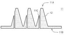
そしてモールド型1から被加工物10を離型することにより、成形品としてのマイクロニードルシート11を製造することができる。このマイクロニードルシート11は、マイクロニードル12を皮膚に刺すことにより、医療又は美容目的での注射針などに使用されることが想定されている。 And the microneedle sheet |
注射針として使用される場合、マイクロニードルシート11は、必要に応じて所定のサイズにカットされた後、目的物質が入ったアプリケータが底面11B側に装着されると共に、使用時以外において目的物質が漏れないよう、人体に刺されたときに簡単に溶けるキャップ(図示しない)が孔11Cにおける先端11A側に装着される。 When used as an injection needle, the
このように、モールド型1と棒部6とを取り外し可能に構成することにより、モールド法を使用して中空タイプのマイクロニードルシート11を簡易に製造することが可能である。また、モールド型1に突出部を形成せずに済み、モールド型1の製造コストや耐久性を向上させることができる。更には、中空形成としてのサイズ、位置などの自由度を持たせる事が可能となる。 In this way, by configuring the mold 1 and the
<第2の実施の形態>
次に、図6〜図9を用いて第2の実施の形態について説明する。なお、図1〜5を用いて説明した第1の実施の形態とは、被加工物に対する加工方法が相違している。なお、第1の実施の形態と対応する箇所に100を加算した符号を附し、第1の実施の形態と同一箇所についての説明は省略する。<Second Embodiment>
Next, a second embodiment will be described with reference to FIGS. In addition, the processing method with respect to a to-be-processed object is different from 1st Embodiment demonstrated using FIGS. In addition, the code | symbol which added 100 to the location corresponding to 1st Embodiment is attached | subjected, and description about the same location as 1st Embodiment is abbreviate | omitted.
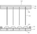
本実施の形態では、図6に示すように、板状の台座板101,103に貫通孔102,104がそれぞれ形成されている。台座板101,103は、成形品としてのマイクロニードルシート111(図9参照)においてシート部分を構成するものであり、その材質に制限はない。金属、樹脂材料など種々の材質を使用することができるが、被加工物110に対して濡れ性が高く、接着性が良好な材料が選択されることが好ましい。また、ぬれ性や接着性を向上させるため、台座板101,103の表面に凹凸を形成したり、プラズマ処理を施したり、アンカー剤、プライマー剤又は粘着剤などを塗布するなどして表面を改質することもできる。なお、台座板101の剛性が不足する場合には、台座板101と同様に貫通孔が形成された支持板を重ねて使用しても良い。 In the present embodiment, as shown in FIG. 6, through
台座板101における貫通孔102上には、所定量の粘性を有する液体又は半液体状の被加工物110が粒状に配置される。また、台座板101上には、スペーサ109が配置される。なお、被加工物110の配置量は、マイクロニードルの体積の約2倍である。液体又は半液体状とは、常温(25℃)における粘度が300〜30000mPa・s/6rpm、より好ましくは1000〜20000mPa・sであることをいい、流動性の高い液体からチキソ性の高いジェル状の状態のものを含む。台座板103の貫通孔104には、予め棒状部材105の棒部106が貫通され、台座板103と板部107が接触した状態にセットされている。 On the through
そして図7に示すように、被加工物110を突き抜けるようにして棒状部材105の棒部106が貫通され、スペーサ109による隙間空間を介して台座板101及び103が対向する。スペーサ109の高さは、台座板101及び103の両方に被加工物110が接触するように設定されている。 Then, as shown in FIG. 7, the
図8に示すように、台座板103をゆっくり引き上げる(又は台座板101を引き下げる)と、台座板101,103近傍の上下(根元)部分は太くなる一方、中心付近が細くなる。この状態で被加工物110を固化させ、棒状部材105を引き抜いた後、中心部分でカットすると、図9に示すように、マイクロニードル112を製造することができる。 As shown in FIG. 8, when the
また、中心部分が千切れるまで台座板103を引き上げて被加工物を固化させてから棒状部材105を引き抜くこともできる。この場合、中心部分でカットする工程が省略できる。液状又は半液状における被加工物110や、固化後の被加工物110の特性によって引き上げる速度や引き上げる距離を適宜選択することが可能である。 Further, the
このように、第2の実施の形態では、2枚の台座板101,103で粒状の被加工物を挟むと共に、被加工物110のほぼ中心に形成された貫通孔102,104に対して棒状部材105を挿入し、2枚の台座板101,103を引き離すことにより、マイクロニードル112を形成するようにした。これにより、簡易な工程で中空のマイクロニードルシート111を製造することができる。 As described above, in the second embodiment, the granular workpiece is sandwiched between the two
<動作及び効果>
以上の構成において、図10に示すように、本発明のマイクロニードルの製造方法は、
ステップS11(成形ステップ)において、貫通孔に細い棒状部材(棒状部材5)を貫通させ、液状又は半液状の液状高分子化合物(被加工物10)に前記棒状部材を貫通させた状態でマイクロニードル(マイクロニードル12)の形状を決定し、
ステップS12(固化ステップ)において、前記高分子化合物を固化させ、
ステップS13(引抜ステップ)において、前記棒状部材を引き抜くことを特徴とする。<Operation and effect>
In the above configuration, as shown in FIG.
In step S11 (molding step), a microneedle is formed in a state where a thin rod-like member (rod-like member 5) is passed through the through-hole and the rod-like member is penetrated through a liquid or semi-liquid liquid polymer compound (workpiece 10). Determine the shape of the (microneedle 12)
In step S12 (solidification step), the polymer compound is solidified,
In step S13 (extraction step), the rod-shaped member is extracted.
これにより、予め貫通させた棒状部材を引き抜くだけで中空構造を形成することができるため、簡易な工程で中空タイプのマイクロニードルを製造できる。 Thereby, since a hollow structure can be formed only by pulling out the rod-shaped member penetrated beforehand, a hollow type microneedle can be manufactured by a simple process.
前記成形ステップ及び前記固化ステップでは、
複数のマイクロニードルが同時に形成され、
前記棒状部材は、
前記複数のマイクロニードルに対応する複数の棒が板状部材に固定されている
ことを特徴とするに請求項1に記載のマイクロニードルの製造方法。In the molding step and the solidifying step,
A plurality of microneedles are formed simultaneously,
The rod-shaped member is
The method for manufacturing a microneedle according to claim 1, wherein a plurality of rods corresponding to the plurality of microneedles are fixed to a plate-like member.
これにより、複数のマイクロニードルを同時に製造できるため、簡易な工程で大量生産が可能である。 Thereby, since a plurality of microneedles can be manufactured simultaneously, mass production is possible with a simple process.
前記成形ステップ及び前記固化ステップにおいて、
前記板状部材と前記貫通孔との間に隙間が形成され、
前記引抜ステップでは、
前記棒状部材を前記貫通孔に近づく方向へと移動させた後、前記棒状部材を前記固化された高分子化合物から引き抜くことを特徴とする。In the molding step and the solidifying step,
A gap is formed between the plate member and the through hole,
In the drawing step,
The rod-shaped member is pulled out from the solidified polymer compound after the rod-shaped member is moved in a direction approaching the through hole.
これにより、隙間を利用して棒状部材を高分子化合物へ向かって押す方向へと一旦移動させてから棒状部材を引き抜くことができるため、棒状部材の引抜き動作を簡易にできる。 Thereby, since the rod-shaped member can be pulled out after temporarily moving the rod-shaped member toward the polymer compound using the gap, the pulling-out operation of the rod-shaped member can be simplified.
前記成形ステップでは、
マイクロニードルを形成するための凹部と当該凹部内に設けられた貫通孔とを有するモールド型に対し、前記貫通孔から突出するように細い棒状部材を貫通させて貫通モールド型を形成した後、前記貫通モールド型に前記液状高分子化合物を流し込むことを特徴とする。In the molding step,
For a mold having a recess for forming a microneedle and a through hole provided in the recess, after forming a through mold by penetrating a thin rod-like member so as to protrude from the through hole, The liquid polymer compound is poured into a through mold.
これにより、棒状部材に対応する突出部分をモールド型と一体形成する必要がないため、簡易な構成で貫通モールド型を形成することができる。 Thereby, since it is not necessary to form the protrusion part corresponding to a rod-shaped member integrally with a mold type | mold, a penetration mold type | mold can be formed with a simple structure.
固化した高分子化合物から前記棒状部材が抜かれたのち、前記固化した高分子化合物を成形品として前記貫通モールド型から外す成形品離型ステップを有することを特徴とする。 After the rod-shaped member is pulled out from the solidified polymer compound, a molded product release step of removing the solidified polymer compound as a molded product from the penetration mold is provided.
これにより、棒状部材がない状態で離型を行うため、棒状部材と相違する方向に力和加えた場合でも、棒状部材の破損や、棒状部材に起因する成形品の変形などを未然に防止することができる。 As a result, the mold release is performed in the absence of the bar-like member, so that even when a force is applied in a direction different from that of the bar-like member, damage to the bar-like member, deformation of the molded product due to the bar-like member, and the like can be prevented. be able to.
前記成形ステップでは、
台座板に形成された前記貫通孔上に前記液状高分子化合物を粒状にして配置し、前記棒状部材を前記貫通孔に貫通させた状態で、板状部材から前記棒状部材が突出した棒板部材を前記台座板に対向させて前記液状高分子化合物に接触させた後、前記棒板部材を引き上げることを特徴とする。In the molding step,
A bar plate member in which the liquid polymer compound is arranged in a granular form on the through hole formed in the base plate, and the bar member protrudes from the plate member in a state in which the bar member is passed through the through hole. The rod plate member is pulled up after the plate is brought into contact with the liquid polymer compound so as to face the pedestal plate.
これにより、モールド型から離型する作業などが不要となり、マイクロニードルを簡易な工程で製造することができると共に、液状高分子化合物の粘性やチキソ性などの選択により、モールド型を使用した場合と比して先端をより細くすることが可能である。また、モールド型が不要であるため、製造工程に必要な道具が少なくて済み、大量生産に好適である。 This eliminates the need to release the mold from the mold, makes it possible to manufacture the microneedle in a simple process, and uses the mold by selecting the viscosity and thixotropy of the liquid polymer compound. The tip can be made thinner than that. Moreover, since a mold is not required, fewer tools are required for the manufacturing process, which is suitable for mass production.
前記成形ステップでは、
前記棒状部材と前記液状高分子化合物との間に、前記棒が貫通孔に貫通された状態の第2の台座板が配置されることを特徴とする。In the molding step,
Between the rod-shaped member and the liquid polymer compound, a second pedestal plate in which the rod is penetrated through a through hole is arranged.
これにより、上下で同じマイクロニードルシートを作製することができるため、マイクロニードルの大量生産が可能となる。 Thereby, since the same microneedle sheet | seat can be produced up and down, mass production of microneedle is attained.
前記成形ステップでは、
前記液状高分子化合物が前記台座板と前記棒板部材との間で切れるまで前記板状部材を引き上げることを特徴とする。In the molding step,
The plate member is pulled up until the liquid polymer compound is cut between the base plate and the bar plate member.
これにより、中心をカットする工程が不要となり、工程を簡易にすることができると共に、マイクロニードルの先端を極めて細くすることができる。 Thereby, the process of cutting the center becomes unnecessary, the process can be simplified, and the tip of the microneedle can be made extremely thin.
前記固化ステップでは、
前記液状高分子化合物が前記台座板と前記棒板部材との間で繋がっている状態で前記液状高分子化合物を固化し、
前記引抜きステップの後に、前記台座板の中心近傍で固化した液状高分子化合物をカットすることを特徴とする。In the solidification step,
Solidifying the liquid polymer compound in a state where the liquid polymer compound is connected between the base plate and the bar plate member,
After the drawing step, the liquid polymer compound solidified near the center of the base plate is cut.
これにより、マイクロニードルの先端の径を調整することができるため、マイクロニードルの強度の維持が可能となる。 Thereby, since the diameter of the tip of the microneedle can be adjusted, the strength of the microneedle can be maintained.
前記液状高分子化合物は、
粘性のある液体又は半液状であることを特徴とする。The liquid polymer compound is
It is characterized by being a viscous liquid or semi-liquid.
これにより、液状高分子化合物の粘性を利用して、マイクロニードルの先端部分をより長くすることが可能となる。 This makes it possible to make the tip portion of the microneedle longer by utilizing the viscosity of the liquid polymer compound.
前記台座板は、
表面改質処理が施されていることを特徴とする。The base plate is
A surface modification treatment is performed.
これにより、液状高分子化合物の台座板表面に対するぬれ及び固化したマイクロニードルの台座板に対する密着性を調整することができる。 Thereby, the wetness with respect to the base plate surface of a liquid polymer compound and the adhesiveness with respect to the base plate of the solidified microneedle can be adjusted.
前記第1の台座板は、
前記マイクロニードルを接続するシート部として使用されることを特徴とする。The first base plate is
It is used as a seat portion for connecting the microneedles.
これにより、複数のマイクロニードルを有するマイクロニードルシートを簡易な工程で製造することができる。 Thereby, the microneedle sheet | seat which has several microneedle can be manufactured in a simple process.
<他の実施の形態>
なお上述実施形態では、スペーサ9を用いたが、本発明はこれに限らず、スペーサは必須でない。<Other embodiments>
In the above embodiment, the spacer 9 is used. However, the present invention is not limited to this, and the spacer is not essential.
本発明は、例えば注射用途でのマイクロニードルに適用することができる。 The present invention can be applied to, for example, a microneedle for injection use.
1 :モールド型
2 :突起用凹部
3,102,104 :貫通孔
5,105 :棒状部材
6,106 :棒部
7,107 :板部
9,109 :スペーサ
10,110 :被加工物
11,111 :マイクロニードルシート
11A :先端
11B :底面
11C :孔
12,112 :マイクロニードル
101,103 :台座板
1: Mold die 2: Protrusion recesses 3, 104, 104: Through
Claims (12)
Translated fromJapanese前記液状高分子化合物を固化させる固化ステップと、
前記隙間空間を利用して前記板状部材を前記貫通孔材に近づく方向へと移動させた後、前記板状部材を前記貫通孔材から遠ざかる方向へ移動させて前記棒部を前記固化させた高分子化合物から引き抜く引抜ステップと
を有することを特徴とするマイクロニードルの製造方法。In the rod-shaped member having a rod portion fixed to the plate-like member, the rod portion is penetrated through the through-hole,and a gap space is formed between the through-hole material in which the through-hole is formed and the plate-like member. A molding step for determining the shape of the microneedle in a state where therod portion is penetrated by a semi-liquid liquid polymer compound;
A solidifying step for solidifying theliquid polymer compound;
After moving the plate-like member in a direction approaching the through-hole material using the gap space, the plate-like member is moved in a direction away from the through-hole material to solidify the rod portion. A method for producing a microneedle, comprising a drawing step of drawingfrom a polymer compound .
複数のマイクロニードルが同時に形成され、
前記棒状部材は、
前記複数のマイクロニードルに対応する複数の棒部が前記板状部材に固定されている
ことを特徴とするに請求項1に記載のマイクロニードルの製造方法。In the molding step and the solidifying step,
A plurality of microneedles are formed simultaneously,
The rod-shaped member is
The method of manufacturing a microneedle according to claim 1,wherein a plurality ofrod portions corresponding to the plurality of microneedles are fixed to the plate-like member.
前記板状部材と前記貫通孔材との間にスペーサが配置されることにより、前記前記隙間空間が形成される
ことを特徴とする請求項2に記載のマイクロニードルの製造方法。In the molding step and the solidifying step,
The method of manufacturing a microneedle according to claim 2,wherein the gap space is formed by arranging a spacer between the plate-like member and the through holematerial .
マイクロニードルを形成するための凹部と当該凹部内に設けられた前記貫通孔を有する前記貫通孔材としてのモールド型に対し、前記貫通孔から突出するように前記棒部を貫通させて貫通モールド型を形成した後、前記貫通モールド型に前記液状高分子化合物を流し込む
ことを特徴とする請求項1〜請求項3のいずれかに記載のマイクロニードルの製造方法。In the molding step,
The mold partas the through hole material having the concave part for forming the microneedle and the through hole provided in the concavepart is penetrated by therod part soas to protrude from the through hole. The microneedle manufacturing method according to any one of claims 1 to 3, wherein the liquid polymer compound is poured into the through mold after forming.
第1の台座板に形成された前記貫通孔上に前記液状高分子化合物を粒状にして配置し、前記棒部を前記貫通孔に貫通させた状態で、前記棒状部材を前記第1の台座板に対向させて前記液状高分子化合物に接触させた後、前記棒状部材を引き上げる
ことを特徴とする請求項1〜請求項3のいずれかに記載のマイクロニードルの製造方法。In the molding step,
First to the formed the through hole on the pedestal plate wherein the liquid polymer compound disposed granulated, in a state in whichthe rod portion is passed through the through hole, the said rod-like member first seat plate The method of manufacturing a microneedle according to any one of claims 1 to 3, wherein the rod-shaped member is pulled up after being brought into contact with the liquid polymer compound.
前記液状高分子化合物を固化させる固化ステップと、
前記棒部を前記固化させた高分子化合物から引き抜く引抜ステップと
を有することを特徴とするマイクロニードルの製造方法。Aliquid or semi-liquid liquid polymer compound is arranged in a granular form on the through hole formed in the first base plate,and the rod portion in the rod member having a rod portion fixed to the plate member is formed in the through hole.The rod-shaped member is opposed to the first pedestal plate in contact with the liquid polymer compound with therod portion penetrating the through-hole, and then the rod-shaped member is pulled up.A molding stepfor determining the shape of the microneedle in a state where the rod portion is penetrated through the liquid polymer compound ;
A solidifying step for solidifying theliquid polymer compound;
And a drawing step of drawing therod part from thesolidified polymer compound.
前記棒状部材と前記液状高分子化合物との間に、前記棒が前記貫通孔に貫通された状態の第2の台座板が配置される
ことを特徴とする請求項6に記載のマイクロニードルの製造方法。In the molding step,
The microneedle manufacturing method according to claim 6, wherein a second pedestal plate in which the rod is penetrated through the through hole is disposed between the rod-shaped member and the liquid polymer compound. Method.
前記液状高分子化合物が前記第1の台座板と前記棒状部材との間で切れるまで前記板状部材を引き上げる
ことを特徴とする請求項6又は請求項7のいずれかに記載のマイクロニードルの製造方法。In the molding step,
8. The microneedle according to claim 6, wherein the liquid polymer compound is pulled up until the liquid polymer compound is cut between the first base plate and the rod-shaped member. Method.
前記液状高分子化合物が前記第1の台座板と前記棒状部材との間で繋がっている状態で前記液状高分子化合物を固化し、
前記引抜ステップの後に、前記第1の台座板及び前記棒状部材の中心近傍で固化した液状高分子化合物をカットする
ことを特徴とする請求項6又は請求項7のいずれかに記載のマイクロニードルの製造方法。In the solidification step,
Solidifying the liquid polymer compound in a state where the liquid polymer compound is connected between the first base plate and the rod-shaped member;
The liquid needle compound solidified near the center of the first base plate and the rod-shaped member is cut after the drawing step. The microneedle according to any one of claims 6 and 7, Production method.
粘性のある液体又は半液状である
ことを特徴とする請求項6〜請求項9のいずれかに記載のマイクロニードルの製造方法。The liquid polymer compound is
It is a viscous liquid or a semi-liquid. The manufacturing method of the microneedle in any one of Claims 6-9 characterized by the above-mentioned.
表面改質処理が施されている
ことを特徴とする請求項6〜請求項10のいずれかに記載のマイクロニードルの製造方法。The first base plate is
The method for producing a microneedle according to any one of claims 6 to 10, wherein surface modification treatment is performed.
前記マイクロニードルを接続するシート部として使用される
ことを特徴とする請求項6〜請求項11のいずれかに記載のマイクロニードルの製造方法。The first base plate is
It is used as a sheet | seat part which connects the said microneedle. The manufacturing method of the microneedle in any one of Claims 6-11 characterized by the above-mentioned.
Applications Claiming Priority (3)
| Application Number | Priority Date | Filing Date | Title |
|---|---|---|---|
| JP2017088370 | 2017-04-27 | ||
| JP2017088370 | 2017-04-27 | ||
| PCT/JP2018/013740WO2018198675A1 (en) | 2017-04-27 | 2018-03-30 | Microneedle production method |
Publications (2)
| Publication Number | Publication Date |
|---|---|
| JP6421393B1true JP6421393B1 (en) | 2018-11-14 |
| JPWO2018198675A1 JPWO2018198675A1 (en) | 2019-06-27 |
Family
ID=63919059
Family Applications (1)
| Application Number | Title | Priority Date | Filing Date |
|---|---|---|---|
| JP2018517239AExpired - Fee RelatedJP6421393B1 (en) | 2017-04-27 | 2018-03-30 | Manufacturing method of microneedle |
Country Status (5)
| Country | Link |
|---|---|
| US (1) | US20210100994A1 (en) |
| EP (1) | EP3616744A4 (en) |
| JP (1) | JP6421393B1 (en) |
| CN (1) | CN110545879A (en) |
| WO (1) | WO2018198675A1 (en) |
Families Citing this family (7)
| Publication number | Priority date | Publication date | Assignee | Title |
|---|---|---|---|---|
| JP6850457B2 (en)* | 2019-03-12 | 2021-03-31 | シンクランド株式会社 | How to collect the stratum corneum |
| CN112426514B (en)* | 2020-11-26 | 2023-02-28 | 南京鼓楼医院 | A gastric target oral macromolecule carrier and its preparation method |
| CN112843461A (en)* | 2021-01-07 | 2021-05-28 | 上海揽微医学科技有限公司 | Soluble microneedle fabrication systems and methods |
| CA3235026A1 (en)* | 2021-10-15 | 2023-04-20 | Thomas M. LIJNSE | Microneedle and array and method of fabricating same |
| WO2024237204A1 (en)* | 2023-05-12 | 2024-11-21 | Asti株式会社 | Microneedle manufacturing method, microneedle, and microneedle unit |
| CN119588891B (en)* | 2024-12-05 | 2025-09-23 | 哈尔滨工业大学 | Preparation method of hollow microneedle and mold thereof |
| CN119589855A (en)* | 2024-12-05 | 2025-03-11 | 哈尔滨工业大学 | A novel preparation device and method for hollow microneedles |
Citations (3)
| Publication number | Priority date | Publication date | Assignee | Title |
|---|---|---|---|---|
| US20060025717A1 (en)* | 2003-04-18 | 2006-02-02 | The Regents Of The University Of California | Method for forming hollow out-of-plane microneedles and devices formed hereby |
| DE102008052702A1 (en)* | 2008-10-22 | 2010-04-29 | Hahn-Schickard-Gesellschaft für angewandte Forschung e.V. | Needle arrangement e.g. plastic injection molding part, for use in e.g. pharmaceutical industry, has needle with part arranged at distance from insertion end of needle such that surface of object rests on receiving surface |
| CN102526870A (en)* | 2012-01-09 | 2012-07-04 | 上海交通大学 | Anomalous plane hollow microneedle based on surface micro processing process and preparation method thereof |
Family Cites Families (9)
| Publication number | Priority date | Publication date | Assignee | Title |
|---|---|---|---|---|
| CN100349629C (en)* | 2001-09-12 | 2007-11-21 | 贝克顿迪肯森公司 | Microneedle-based pen device for drug delivery and method of using same |
| CA2587387C (en)* | 2004-11-18 | 2013-06-25 | 3M Innovative Properties Company | Method of contact coating a microneedle array |
| KR100781702B1 (en)* | 2006-07-21 | 2007-12-03 | 연세대학교 산학협력단 | Hollow microneedle and manufacturing method thereof |
| US20120150023A1 (en)* | 2007-08-06 | 2012-06-14 | Kaspar Roger L | Microneedle arrays for active agent delivery |
| CN100591388C (en)* | 2008-01-04 | 2010-02-24 | 南京大学 | A kind of preparation method of microneedle array syringe |
| CN101332327A (en)* | 2008-08-06 | 2008-12-31 | 清华大学 | A kind of micro hollow silicon needle and preparation method thereof |
| JP5495034B2 (en) | 2010-02-22 | 2014-05-21 | コスメディ製薬株式会社 | Multi-needle microneedle patch |
| KR101254240B1 (en)* | 2010-12-17 | 2013-04-12 | 주식회사 라파스 | Process for preparing microstructures |
| KR101698846B1 (en)* | 2016-06-23 | 2017-01-23 | 이상혁 | Method and apparatus for manufacturing micro needle, micro needle and computer readable recording medium |
- 2018
- 2018-03-30JPJP2018517239Apatent/JP6421393B1/ennot_activeExpired - Fee Related
- 2018-03-30WOPCT/JP2018/013740patent/WO2018198675A1/ennot_activeCeased
- 2018-03-30USUS16/608,273patent/US20210100994A1/ennot_activeAbandoned
- 2018-03-30CNCN201880026724.XApatent/CN110545879A/enactivePending
- 2018-03-30EPEP18791681.2Apatent/EP3616744A4/ennot_activeWithdrawn
Patent Citations (3)
| Publication number | Priority date | Publication date | Assignee | Title |
|---|---|---|---|---|
| US20060025717A1 (en)* | 2003-04-18 | 2006-02-02 | The Regents Of The University Of California | Method for forming hollow out-of-plane microneedles and devices formed hereby |
| DE102008052702A1 (en)* | 2008-10-22 | 2010-04-29 | Hahn-Schickard-Gesellschaft für angewandte Forschung e.V. | Needle arrangement e.g. plastic injection molding part, for use in e.g. pharmaceutical industry, has needle with part arranged at distance from insertion end of needle such that surface of object rests on receiving surface |
| CN102526870A (en)* | 2012-01-09 | 2012-07-04 | 上海交通大学 | Anomalous plane hollow microneedle based on surface micro processing process and preparation method thereof |
Also Published As
| Publication number | Publication date |
|---|---|
| EP3616744A1 (en) | 2020-03-04 |
| EP3616744A4 (en) | 2020-05-27 |
| JPWO2018198675A1 (en) | 2019-06-27 |
| US20210100994A1 (en) | 2021-04-08 |
| WO2018198675A1 (en) | 2018-11-01 |
| CN110545879A (en) | 2019-12-06 |
Similar Documents
| Publication | Publication Date | Title |
|---|---|---|
| JP6421393B1 (en) | Manufacturing method of microneedle | |
| CA3007753C (en) | Microstructure for transdermal absorption and method for manufacturing same | |
| JP2011012050A (en) | Microneedle array using porous substrate and method for producing the same | |
| US10850083B2 (en) | Method for manufacturing microneedle by using biocompatible polymer | |
| JP6038173B2 (en) | Method for producing transdermal absorption sheet | |
| US20180250851A1 (en) | Manufacturing method of pattern sheet | |
| KR102074603B1 (en) | Manufacturing method of mold, manufacturing method of pattern sheet, manufacturing method of electroforming mold, and manufacturing method of mold using electroforming mold | |
| CN104321105B (en) | Micropin and microneedle array | |
| EP2823850A1 (en) | Polymer micro-needle array chip, preparation process and use thereof | |
| JP5542404B2 (en) | Manufacturing method of microneedle stamper | |
| CN104780968A (en) | Transdermal absorption sheet, and manufacturing method for same | |
| JP2013153866A (en) | Transdermal absorption sheet and method for manufacturing transdermal absorption sheet | |
| JP2009082206A (en) | Method for producing functional membrane | |
| KR102249834B1 (en) | Manufacturing method of microneedl patch | |
| EP3243624B1 (en) | Production method of mold, manufacturing method of pattern sheet, production method of electroform, production method of mold using electroform, and original | |
| JP6681378B2 (en) | Microneedle and manufacturing method thereof | |
| JP6269068B2 (en) | Manufacturing method of microneedle | |
| JPWO2019059265A1 (en) | Microneedle sheet and method for manufacturing microneedle sheet | |
| JP6691025B2 (en) | Method for manufacturing needle-shaped array sheet | |
| CN105434332A (en) | Preparation method for water-soluble biological macromolecular microneedle membrane | |
| CN107427671B (en) | Microneedle and manufacturing method thereof | |
| JP2017213171A (en) | Recessed pattern mold, method of manufacturing recessed pattern mold, and method of manufacturing pattern sheet | |
| JP2015208922A (en) | Method for producing acicular body |
Legal Events
| Date | Code | Title | Description |
|---|---|---|---|
| A621 | Written request for application examination | Free format text:JAPANESE INTERMEDIATE CODE: A621 Effective date:20180330 | |
| A871 | Explanation of circumstances concerning accelerated examination | Free format text:JAPANESE INTERMEDIATE CODE: A871 Effective date:20180405 | |
| AA64 | Notification of invalidation of claim of internal priority (with term) | Free format text:JAPANESE INTERMEDIATE CODE: A241764 Effective date:20180412 | |
| A521 | Request for written amendment filed | Free format text:JAPANESE INTERMEDIATE CODE: A523 Effective date:20180510 | |
| A975 | Report on accelerated examination | Free format text:JAPANESE INTERMEDIATE CODE: A971005 Effective date:20180619 | |
| A131 | Notification of reasons for refusal | Free format text:JAPANESE INTERMEDIATE CODE: A131 Effective date:20180628 | |
| A521 | Request for written amendment filed | Free format text:JAPANESE INTERMEDIATE CODE: A523 Effective date:20180815 | |
| TRDD | Decision of grant or rejection written | ||
| A01 | Written decision to grant a patent or to grant a registration (utility model) | Free format text:JAPANESE INTERMEDIATE CODE: A01 Effective date:20180830 | |
| A61 | First payment of annual fees (during grant procedure) | Free format text:JAPANESE INTERMEDIATE CODE: A61 Effective date:20180927 | |
| R150 | Certificate of patent or registration of utility model | Ref document number:6421393 Country of ref document:JP Free format text:JAPANESE INTERMEDIATE CODE: R150 | |
| LAPS | Cancellation because of no payment of annual fees | ||
| S531 | Written request for registration of change of domicile | Free format text:JAPANESE INTERMEDIATE CODE: R313531 | |
| R350 | Written notification of registration of transfer | Free format text:JAPANESE INTERMEDIATE CODE: R350 |