JP6421365B2 - Vehicle seat control system, vehicle seat control method, and program - Google Patents
Vehicle seat control system, vehicle seat control method, and programDownload PDFInfo
- Publication number
- JP6421365B2 JP6421365B2JP2017023192AJP2017023192AJP6421365B2JP 6421365 B2JP6421365 B2JP 6421365B2JP 2017023192 AJP2017023192 AJP 2017023192AJP 2017023192 AJP2017023192 AJP 2017023192AJP 6421365 B2JP6421365 B2JP 6421365B2
- Authority
- JP
- Japan
- Prior art keywords
- unit
- frame
- vehicle
- control unit
- seat
- Prior art date
- Legal status (The legal status is an assumption and is not a legal conclusion. Google has not performed a legal analysis and makes no representation as to the accuracy of the status listed.)
- Expired - Fee Related
Links
Images


Classifications
- B—PERFORMING OPERATIONS; TRANSPORTING
- B60—VEHICLES IN GENERAL
- B60N—SEATS SPECIALLY ADAPTED FOR VEHICLES; VEHICLE PASSENGER ACCOMMODATION NOT OTHERWISE PROVIDED FOR
- B60N2/00—Seats specially adapted for vehicles; Arrangement or mounting of seats in vehicles
- B60N2/02—Seats specially adapted for vehicles; Arrangement or mounting of seats in vehicles the seat or part thereof being movable, e.g. adjustable
- B60N2/0224—Non-manual adjustments, e.g. with electrical operation
- B60N2/0244—Non-manual adjustments, e.g. with electrical operation with logic circuits
- B—PERFORMING OPERATIONS; TRANSPORTING
- B60—VEHICLES IN GENERAL
- B60N—SEATS SPECIALLY ADAPTED FOR VEHICLES; VEHICLE PASSENGER ACCOMMODATION NOT OTHERWISE PROVIDED FOR
- B60N3/00—Arrangements or adaptations of other passenger fittings, not otherwise provided for
- B60N3/06—Arrangements or adaptations of other passenger fittings, not otherwise provided for of footrests
- B60N3/063—Arrangements or adaptations of other passenger fittings, not otherwise provided for of footrests with adjustment systems
- B—PERFORMING OPERATIONS; TRANSPORTING
- B60—VEHICLES IN GENERAL
- B60N—SEATS SPECIALLY ADAPTED FOR VEHICLES; VEHICLE PASSENGER ACCOMMODATION NOT OTHERWISE PROVIDED FOR
- B60N2/00—Seats specially adapted for vehicles; Arrangement or mounting of seats in vehicles
- B60N2/02—Seats specially adapted for vehicles; Arrangement or mounting of seats in vehicles the seat or part thereof being movable, e.g. adjustable
- B60N2/0224—Non-manual adjustments, e.g. with electrical operation
- B60N2/0244—Non-manual adjustments, e.g. with electrical operation with logic circuits
- B60N2/0272—Non-manual adjustments, e.g. with electrical operation with logic circuits using sensors or detectors for detecting the position of seat parts
- B—PERFORMING OPERATIONS; TRANSPORTING
- B60—VEHICLES IN GENERAL
- B60N—SEATS SPECIALLY ADAPTED FOR VEHICLES; VEHICLE PASSENGER ACCOMMODATION NOT OTHERWISE PROVIDED FOR
- B60N2/00—Seats specially adapted for vehicles; Arrangement or mounting of seats in vehicles
- B60N2/02—Seats specially adapted for vehicles; Arrangement or mounting of seats in vehicles the seat or part thereof being movable, e.g. adjustable
- B60N2/22—Seats specially adapted for vehicles; Arrangement or mounting of seats in vehicles the seat or part thereof being movable, e.g. adjustable the back-rest being adjustable
- B—PERFORMING OPERATIONS; TRANSPORTING
- B60—VEHICLES IN GENERAL
- B60N—SEATS SPECIALLY ADAPTED FOR VEHICLES; VEHICLE PASSENGER ACCOMMODATION NOT OTHERWISE PROVIDED FOR
- B60N2/00—Seats specially adapted for vehicles; Arrangement or mounting of seats in vehicles
- B60N2/90—Details or parts not otherwise provided for
- B60N2/914—Hydro-pneumatic adjustments of the shape
- B—PERFORMING OPERATIONS; TRANSPORTING
- B60—VEHICLES IN GENERAL
- B60N—SEATS SPECIALLY ADAPTED FOR VEHICLES; VEHICLE PASSENGER ACCOMMODATION NOT OTHERWISE PROVIDED FOR
- B60N2/00—Seats specially adapted for vehicles; Arrangement or mounting of seats in vehicles
- B60N2/90—Details or parts not otherwise provided for
- B60N2/995—Lower-leg-rests, e.g. calf-rests
- B—PERFORMING OPERATIONS; TRANSPORTING
- B60—VEHICLES IN GENERAL
- B60R—VEHICLES, VEHICLE FITTINGS, OR VEHICLE PARTS, NOT OTHERWISE PROVIDED FOR
- B60R16/00—Electric or fluid circuits specially adapted for vehicles and not otherwise provided for; Arrangement of elements of electric or fluid circuits specially adapted for vehicles and not otherwise provided for
- B60R16/02—Electric or fluid circuits specially adapted for vehicles and not otherwise provided for; Arrangement of elements of electric or fluid circuits specially adapted for vehicles and not otherwise provided for electric constitutive elements
- B60R16/037—Electric or fluid circuits specially adapted for vehicles and not otherwise provided for; Arrangement of elements of electric or fluid circuits specially adapted for vehicles and not otherwise provided for electric constitutive elements for occupant comfort, e.g. for automatic adjustment of appliances according to personal settings, e.g. seats, mirrors, steering wheel
Landscapes
- Engineering & Computer Science (AREA)
- Mechanical Engineering (AREA)
- Transportation (AREA)
- Aviation & Aerospace Engineering (AREA)
- Seats For Vehicles (AREA)
- Passenger Equipment (AREA)
Description
Translated fromJapanese本発明は、車両シート制御システム、車両シートの制御方法、およびプログラムに関する。 The present invention relates to a vehicle seat control system, a vehicle seat control method, and a program.
従来、乗員の着座を快適にするために車両用シートに足載せ台を設けたものがある。特許文献1には、シートの着座部から出し入れ自在な足載せ台について記載されている。この足載せ台は、着座部から出し入れ自在な可動台座と、台座に対して回転自在に軸支された足載せ部材とを備えている。 2. Description of the Related Art Conventionally, there is a vehicle seat provided with a footrest in order to make a passenger seat comfortably.
ところで、近年、自動運転に関しても実用化が進められている。それに伴い、車両の走行状態に基づいて、乗員が着座するシートの機能を制御する技術についての研究が進められている。車両が自動運転モードの際に、乗員はシートから足載せ台等を用いてリラックス姿勢をとる場合がある。しかしながら、従来の技術では、車両の運転モードの変化に応じて、足載せ台を制御して乗員のリラックス姿勢を保つことは行われていなかった。 By the way, in recent years, practical use is also being promoted regarding automatic driving. Along with this, research on a technique for controlling the function of a seat on which an occupant is seated is being advanced based on the running state of the vehicle. When the vehicle is in the automatic driving mode, the occupant may take a relaxed posture from the seat using a footrest or the like. However, in the prior art, it has not been possible to maintain a relaxed posture of the occupant by controlling the footrest according to changes in the driving mode of the vehicle.
本発明は、このような事情を考慮してなされたものであり、車両の走行状態に応じて乗員の脚部を支持するための制御を行うことができる車両シート制御システム、車両シートの制御方法、およびプログラムを提供することを目的とする。 The present invention has been made in consideration of such circumstances, and a vehicle seat control system and a vehicle seat control method capable of performing control for supporting a leg portion of an occupant in accordance with a running state of the vehicle. And to provide a program.
請求項1に記載の発明は、座面部と背もたれ部とを回転自在に連結する連結部の角度を検出する角度検出部と、一対の縦枠と、前記一対の縦枠同士を連結する横枠とを備え、前記座面部に収納自在に設けられた枠体と、前記横枠の延在方向に平行な第1回転軸を有し、前記枠体の内側に前記枠体に対して回転自在に設けられた脚支持部と、前記一対の縦枠の少なくとも一方の基端に設けられ、前記座面部から出された状態の前記枠体を前記横枠の延在方向に平行な第2回転軸周りに回転させる駆動部と、車両の少なくとも自動運転時に、前記角度検出部の検出結果に基づいて前記駆動部を制御する制御部と、を備える、車両シート制御システムである。 The invention according to
請求項2に記載の発明は、請求項1に記載の車両シート制御システムであって、前記枠体の内側または前記脚支持部の上面のどちらか一方に取り付けられ、乗員の脚部を挟持する形状に膨張可能な袋体部と、前記袋体部を流体によって膨張させる加圧部と、を更に備え、前記制御部は、前記車両の自動運転時に前記加圧部を作動させるものである。 Invention of
請求項3に記載の発明は、請求項2に記載の車両シート制御システムであって、前記枠体は、管状部材で形成され、前記流体は前記管状部材の内部を介して前記袋体部に流入されるものである。 Invention of
請求項4に記載の発明は、請求項2または3に記載の車両シート制御システムであって、前記制御部は、前記乗員の操作に基づいて前記加圧部の制御態様を変更するものである。 Invention of
請求項5に記載の発明は、請求項2から4のいずれか1項に記載の車両シート制御システムであって、前記座面部から前記枠体が出し入れされたことを検出する検出部を更に備え、前記制御部は、前記検出部の検出結果に基づいて前記駆動部及び前記加圧部の制御を開始するものである。 A fifth aspect of the present invention is the vehicle seat control system according to any one of the second to fourth aspects, further comprising a detection unit that detects that the frame body has been taken in and out of the seat surface portion. The control unit starts control of the drive unit and the pressurizing unit based on the detection result of the detection unit.
請求項6に記載の発明は、請求項2から5のいずれか1項に記載の車両シート制御システムであって、前記袋体部に温度変化を与える熱源部を更に備え、前記制御部は、乗員の操作に基づいて前記熱源部を制御して前記袋体部に温度変化を与えるものである。 Invention of Claim 6 is a vehicle seat control system of any one of Claim 2-5, Comprising: The heat source part which gives a temperature change to the said bag body part is further provided, The said control part is The heat source part is controlled based on the operation of the passenger to give a temperature change to the bag body part.
請求項7に記載の発明は、一対の縦枠と、前記一対の縦枠同士を連結する横枠とを備え、座面部に収納自在に設けられた枠体と、前記横枠の延在方向に平行な第1回転軸を有し、前記枠体の内側に前記枠体に対して回転自在に設けられた脚支持部と、前記一対の縦枠の少なくとも一方の基端に設けられ、座面部から出された状態の前記枠体を前記横枠の延在方向に平行な第2回転軸周りに回転させる駆動部と、を備える車両用シートの制御方法であって、コンピュータに、前記座面部と背もたれ部とを回転自在に連結する連結部の角度を検出させ、車両の少なくとも自動運転時に、検出結果に基づいて前記駆動部を制御させる、車両シートの制御方法である。 The invention according to claim 7 is provided with a pair of vertical frames and a horizontal frame connecting the pair of vertical frames, and a frame body that can be stored in a seating surface portion, and an extending direction of the horizontal frame A leg support portion provided on the inner side of the frame body so as to be rotatable with respect to the frame body, and provided at a base end of at least one of the pair of vertical frames, A vehicle seat control method comprising: a drive unit configured to rotate the frame body in a state of being protruded from a surface part around a second rotation axis parallel to an extending direction of the horizontal frame, the computer comprising the seat This is a vehicle seat control method in which an angle of a connecting portion that rotatably connects a surface portion and a backrest portion is detected, and the driving portion is controlled based on a detection result at least during automatic driving of the vehicle.
請求項8に記載の発明は、一対の縦枠と、前記一対の縦枠同士を連結する横枠とを備え、座面部に収納自在に設けられた枠体と、前記横枠の延在方向に平行な第1回転軸を有し、前記枠体の内側に前記枠体に対して回転自在に設けられた脚支持部と、前記一対の縦枠の少なくとも一方の基端に設けられ、座面部から出された状態の前記枠体を前記横枠の延在方向に平行な第2回転軸周りに回転させる駆動部と、を備える、車両用シートの制御プログラムであって、コンピュータが、前記座面部と背もたれ部とを回転自在に連結する連結部の角度を検出し、車両の少なくとも自動運転時に、検出結果に基づいて前記駆動部を制御する、プログラムである。 The invention according to
請求項1、7、8に記載の発明によれば、車両が自動運転中に乗員がシートをリクライニング状態にした場合、足載せ部に関する制御を行うことで乗員の快適性を向上することができる。 According to the first, seventh, and eighth aspects of the present invention, when the occupant puts the seat into the reclining state while the vehicle is in automatic operation, the comfort of the occupant can be improved by performing control related to the footrest portion. .
請求項2に記載の発明によれば、車両が自動運転中に足載せ部に設けられた袋体が加圧部によって膨張し、乗員の脚部に対して経時的変化を伴う加圧状態を与えることができ、乗員の快適性を更に向上することができる。 According to the second aspect of the present invention, the bag provided on the footrest portion is inflated by the pressurizing portion during the automatic driving of the vehicle, and the pressurization state accompanied with a change with time is applied to the occupant's leg portion. The comfort of the passenger can be further improved.
請求項3に記載の発明によれば、袋体の膨張に用いられる流体の配管は、枠体が兼ねていることで装置構成を簡略化することができる。 According to the third aspect of the present invention, the fluid piping used for the expansion of the bag body can also simplify the device configuration by serving as the frame body.
請求項4に記載の発明によれば、乗員が加圧部の制御態様を操作によって変更することができ、乗員の快適性を向上することができる。 According to the fourth aspect of the present invention, the passenger can change the control mode of the pressurizing unit by operation, and the comfort of the passenger can be improved.
請求項5に記載の発明によれば、検出部が足載せ部の出し入れを検出した後に足載せ部の制御が開始するため、足載せ部の安全性を向上させることができる。 According to the fifth aspect of the present invention, since the control of the footrest portion is started after the detection portion detects the insertion / removal of the footrest portion, the safety of the footrest portion can be improved.
請求項6に記載の発明によれば、袋体に温度変化を与えることで足載せ部を使用している乗員の快適性を更に向上することができる。 According to invention of Claim 6, the comfort of the passenger | crew who uses the footrest part can further be improved by giving a temperature change to a bag body.
以下、図面を参照し、本発明の車両システム、車両制御方法、および車両制御プログラムの実施形態について説明する。車両システムは自動運転車両に適用されるものである。以下でいう自動運転は、車線維持や追従走行を複合的に行う高度運転支援を含んでもよいし、高度運転支援を含まず、車線変更や分岐までを自動的に行う自動運転を指すものであってもよい。 Hereinafter, embodiments of a vehicle system, a vehicle control method, and a vehicle control program of the present invention will be described with reference to the drawings. The vehicle system is applied to an autonomous driving vehicle. The automatic driving described below may include advanced driving support that combines lane maintenance and follow-up driving, or does not include advanced driving support and refers to automatic driving that automatically performs lane change and branching. May be.
<第1実施形態>
[全体構成]
図1は、第1実施形態の車両システム1の構成図である。車両システム1が搭載される車両(以下、車両Mと称する)は、例えば、二輪や三輪、四輪等の車両であり、その駆動源は、ディーゼルエンジンやガソリンエンジン等の内燃機関、電動機、或いはこれらの組み合わせである。電動機は、内燃機関に連結された発電機による発電電力、或いは二次電池や燃料電池の放電電力を使用して動作する。<First Embodiment>
[overall structure]
FIG. 1 is a configuration diagram of a
車両システム1は、例えば、カメラ10と、レーダ装置12と、ファインダ14と、物体認識装置16と、通信装置20と、HMI(Human Machine Interface)30と、ナビゲーション装置50と、MPU(Micro-Processing Unit)60と、車両センサ70と、運転操作子80と、車室内カメラ90と、自動運転制御ユニット100と、走行駆動力出力装置200と、ブレーキ装置210と、ステアリング装置220と、シート装置300と、を備える。これらの装置や機器は、CAN(Controller Area Network)通信線等の多重通信線やシリアル通信線、無線通信網等によって互いに接続される。なお、図1に示す構成はあくまで一例であり、構成の一部が省略されてもよいし、更に別の構成が追加されてもよい。 The
カメラ10は、例えば、CCD(Charge Coupled Device)やCMOS(Complementary Metal Oxide Semiconductor)等の固体撮像素子を利用したデジタルカメラである。カメラ10は、車両システム1が搭載される車両Mの任意の箇所に一つまたは複数が取り付けられる。前方を撮像する場合、カメラ10は、フロントウインドシールド上部やルームミラー裏面等に取り付けられる。後方を撮像する場合、カメラ10は、リアウインドシールド上部やバックドア等に取り付けられる。側方を撮像する場合、カメラ10は、ドアミラー等に取り付けられる。カメラ10は、例えば、周期的に繰り返し車両Mの周辺を撮像する。カメラ10は、ステレオカメラであってもよい。 The
レーダ装置12は、車両Mの周辺にミリ波等の電波を放射するとともに、物体によって反射された電波(反射波)を検出して少なくとも物体の位置(距離および方位)を検出する。レーダ装置12は、車両Mの任意の箇所に一つまたは複数が取り付けられる。レーダ装置12は、FMCW(Frequency Modulated Continuous Wave)方式によって物体の位置および速度を検出してもよい。 The
ファインダ14は、照射光に対する散乱光を測定し、対象までの距離を検出するLIDAR(Light Detection and Ranging、或いはLaser Imaging Detection and Ranging)である。ファインダ14は、車両Mの任意の箇所に一つまたは複数が取り付けられる。 The
物体認識装置16は、カメラ10、レーダ装置12、およびファインダ14のうち一部または全部による検出結果に対してセンサフュージョン処理を行って、物体の位置、種類、速度等を認識する。物体認識装置16は、認識結果を自動運転制御ユニット100に出力する。 The
通信装置20は、例えば、セルラー網やWi−Fi網、Bluetooth(登録商標)、DSRC(Dedicated Short Range Communication)等を利用して、車両Mの周辺に存在する他車両と通信し、或いは無線基地局を介して各種サーバ装置と通信する。また、通信装置20は、車外の人物が所持する端末装置と通信する。 The
HMI30は、車内の乗員に対して各種情報を提示するとともに、乗員による入力操作を受け付ける。HMI30は、例えば、各種表示装置、スピーカ、ブザー、タッチパネル、各種操作スイッチ、キー等である。 The
ナビゲーション装置50は、例えば、GNSS(Global Navigation Satellite System)受信機51と、ナビHMI52と、経路決定部53とを備え、HDD(Hard Disk Drive)やフラッシュメモリ等の記憶装置に第1地図情報54を保持している。GNSS受信機は、GNSS衛星から受信した信号に基づいて、車両Mの位置を特定する。車両Mの位置は、車両センサ70の出力を利用したINS(Inertial Navigation System)によって特定または補完されてもよい。ナビHMI52は、表示装置、スピーカ、タッチパネル、キー等を含む。ナビHMI52は、前述したHMI30と一部または全部が共通化されてもよい。経路決定部53は、例えば、GNSS受信機51により特定された車両Mの位置(或いは入力された任意の位置)から、ナビHMI52を用いて乗員により入力された目的地までの経路(例えば、目的地まで走行するときの経由地に関する情報を含む)を、第1地図情報54を参照して決定する。第1地図情報54は、例えば、道路を示すリンクと、リンクによって接続されたノードとによって道路形状が表現された情報である。第1地図情報54は、道路の曲率やPOI(Point Of Interest)情報等を含んでもよい。経路決定部53により決定された経路は、MPU60に出力される。また、ナビゲーション装置50は、経路決定部53により決定された経路に基づいて、ナビHMI52を用いた経路案内を行ってもよい。なお、ナビゲーション装置50は、例えば、ユーザの保有するスマートフォンやタブレット端末等の端末装置の機能によって実現されてもよい。また、ナビゲーション装置50は、通信装置20を介してナビゲーションサーバに現在位置と目的地を送信し、ナビゲーションサーバから返信された経路を取得してもよい。 The
MPU60は、例えば、推奨車線決定部61として機能し、HDDやフラッシュメモリ等の記憶装置に第2地図情報62を保持している。推奨車線決定部61は、ナビゲーション装置50から提供された経路を複数のブロックに分割し(例えば、車両進行方向に関して100[m]毎に分割し)、第2地図情報62を参照してブロックごとに推奨車線を決定する。推奨車線決定部61は、左から何番目の車線を走行するといった決定を行う。推奨車線決定部61は、経路において分岐箇所や合流箇所等が存在する場合、車両Mが、分岐先に進行するための合理的な走行経路を走行できるように、推奨車線を決定する。 For example, the
第2地図情報62は、第1地図情報54よりも高精度な地図情報である。第2地図情報62は、例えば、車線の中央の情報あるいは車線の境界の情報等を含んでいる。また、第2地図情報62には、道路情報、交通規制情報、住所情報(住所・郵便番号)、施設情報、電話番号情報等が含まれてよい。道路情報には、高速道路、有料道路、国道、都道府県道といった道路の種別を表す情報や、道路の車線数、非常駐車帯の領域、各車線の幅員、道路の勾配、道路の位置(経度、緯度、高さを含む3次元座標)、車線のカーブの曲率、車線の合流および分岐ポイントの位置、道路に設けられた標識等の情報が含まれる。第2地図情報62は、通信装置20を用いて他装置にアクセスすることにより、随時、アップデートされてよい。 The
車両センサ70は、車両Mの速度を検出する車速センサ、加速度を検出する加速度センサ、鉛直軸回りの角速度を検出するヨーレートセンサ、車両Mの向きを検出する方位センサ等を含む。加速度センサは、例えば、車両Mの横方向に関する重力加速度(以下、「横加速度」と称する)を検出する横加速度センサを含んでいてもよい。 The
運転操作子80は、例えば、アクセルペダル、ブレーキペダル、シフトレバー、ステアリングホイールその他の操作子を含む。運転操作子80には、操作量あるいは操作の有無を検出するセンサが取り付けられており、その検出結果は、自動運転制御ユニット100、もしくは、走行駆動力出力装置200、ブレーキ装置210、およびステアリング装置220のうち一方または双方に出力される。 The driving
車室内カメラ90は、例えば、車両Mの室内を撮像する。例えば、車室内カメラ90は、シート装置300またはシート装置300の周囲を撮像する。車室内カメラ90は、例えば、周期的に繰り返し車両Mの室内を撮像する。車室内カメラ90の撮像画像は、自動運転制御ユニット100に出力される。 The vehicle interior camera 90 images the interior of the vehicle M, for example. For example, the vehicle interior camera 90 images the
[自動運転制御ユニット]
自動運転制御ユニット100は、例えば、第1制御部120と、第2制御部140と、インターフェース制御部150と、シート制御部160と、物体判定部170と、挙動取得部180とを備える。第1制御部120と、第2制御部140と、インターフェース制御部150と、シート制御部160と、物体判定部170と、挙動取得部180とは、それぞれ、CPU(Central Processing Unit)等のプロセッサがプログラム(ソフトウェア)を実行することで実現される。また、以下に説明する第1制御部120、第2制御部140、インターフェース制御部150、シート制御部160、物体判定部170、および挙動取得部180の各機能部のうち一部または全部は、LSI(Large Scale Integration)やASIC(Application Specific Integrated Circuit)、FPGA(Field-Programmable Gate Array)等のハードウェアによって実現されてもよいし、ソフトウェアとハードウェアの協働によって実現されてもよい。[Automatic operation control unit]
The automatic
第1制御部120は、例えば、外界認識部121と、自車位置認識部122と、行動計画生成部123とを備える。 The
外界認識部121は、カメラ10、レーダ装置12、およびファインダ14から物体認識装置16を介して入力される情報に基づいて、周辺車両の位置および速度、加速度等の状態を認識する。周辺車両の位置は、その周辺車両の重心やコーナー等の代表点で表されてもよいし、周辺車両の輪郭で表現された領域で表されてもよい。周辺車両の「状態」とは、周辺車両の加速度やジャーク、あるいは「行動状態」(例えば車線変更をしている、またはしようとしているか否か)を含んでもよい。 Based on information input from the
また、外界認識部121は、周辺車両に加えて、ガードレールや電柱、駐車車両、歩行者等の人物、その他の物体の位置を認識してもよい。 In addition to the surrounding vehicles, the external
自車位置認識部122は、例えば、車両Mが走行している車線(走行車線)、並びに走行車線に対する車両Mの相対位置および姿勢を認識する。自車位置認識部122は、例えば、第2地図情報62から得られる道路区画線のパターン(例えば実線と破線の配列)と、カメラ10によって撮像された画像から認識される車両Mの周辺の道路区画線のパターンとを比較することで、走行車線を認識する。この認識において、ナビゲーション装置50から取得される車両Mの位置やINSによる処理結果が加味されてもよい。 The own vehicle position recognition unit 122 recognizes, for example, the lane (traveling lane) in which the vehicle M is traveling, and the relative position and posture of the vehicle M with respect to the traveling lane. The own vehicle position recognition unit 122, for example, a road around the vehicle M recognized from a pattern of road marking lines (for example, an array of solid lines and broken lines) obtained from the
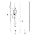
そして、自車位置認識部122は、例えば、走行車線に対する車両Mの位置や姿勢を認識する。図2は、自車位置認識部122により走行車線L1に対する車両Mの相対位置および姿勢が認識される様子を示す図である。自車位置認識部122は、例えば、車両Mの基準点(例えば重心)の走行車線中央CLからの乖離OS、および車両Mの進行方向の走行車線中央CLを連ねた線に対してなす角度θを、走行車線L1に対する車両Mの相対位置および姿勢として認識する。なお、これに代えて、自車位置認識部122は、走行車線L1の何れかの側端部に対する車両Mの基準点の位置等を、走行車線に対する車両Mの相対位置として認識してもよい。自車位置認識部122により認識される車両Mの相対位置は、推奨車線決定部61および行動計画生成部123に提供される。 And the own vehicle position recognition part 122 recognizes the position and attitude | position of the vehicle M with respect to a travel lane, for example. FIG. 2 is a diagram illustrating how the vehicle position recognition unit 122 recognizes the relative position and posture of the vehicle M with respect to the travel lane L1. The own vehicle position recognizing unit 122, for example, an angle θ formed with respect to a line connecting the deviation point OS of the reference point (for example, the center of gravity) of the vehicle M from the travel lane center CL and the travel lane center CL in the traveling direction of the vehicle M. Is recognized as the relative position and posture of the vehicle M with respect to the traveling lane L1. Instead of this, the vehicle position recognition unit 122 may recognize the position of the reference point of the vehicle M with respect to any side end portion of the traveling lane L1 as the relative position of the vehicle M with respect to the traveling lane. . The relative position of the vehicle M recognized by the own vehicle position recognition unit 122 is provided to the recommended
行動計画生成部123は、車両Mが目的地等に対して自動運転を行うための行動計画を生成する。例えば、行動計画生成部123は、推奨車線決定部61により決定された推奨車線を走行するように、且つ、車両Mの周辺状況に対応できるように、自動運転制御において順次実行されるイベントを決定する。第1実施形態の自動運転におけるイベントには、例えば、一定速度で同じ走行車線を走行する定速走行イベント、車両Mの走行車線を変更する車線変更イベント、前走車両を追い越す追い越しイベント、前走車両に追従して走行する追従走行イベント、合流地点で車両を合流させる合流イベント、道路の分岐地点で車両Mを目的の方向に走行させる分岐イベント、車両Mを緊急停車させる緊急停車イベント、自動運転を終了して手動運転に切り替えるための切替イベント等がある。また、これらのイベントの実行中に、車両Mの周辺状況(周辺車両や歩行者の存在、道路工事による車線狭窄等)に基づいて、回避のための行動が計画される場合もある。 The action
行動計画生成部123は、自車両Mが将来走行する目標軌道を生成する。目標軌道は、自車両Mの到達すべき地点(軌道点)を順に並べたものとして表現される。軌道点は、所定の走行距離ごとの自車両Mの到達すべき地点であり、それとは別に、所定のサンプリング時間(例えば0コンマ数[sec]程度)ごとの目標速度および目標加速度が、目標軌道の一部として生成される。また、軌道点は、所定のサンプリング時間ごとの、そのサンプリング時刻における自車両Mの到達すべき位置であってもよい。この場合、目標速度や目標加速度の情報は軌道点の間隔で表現される。 The action
図3は、推奨車線に基づいて目標軌道が生成される様子を示す図である。図示するように、推奨車線は、目的地までの経路に沿って走行するのに都合が良いように設定される。行動計画生成部123は、推奨車線の切り替わり地点の所定距離手前(イベントの種類に応じて決定されてよい)に差し掛かると、車線変更イベント、分岐イベント、合流イベント等を起動する。各イベントの実行中に、障害物を回避する必要が生じた場合には、図示するように回避軌道が生成される。 FIG. 3 is a diagram illustrating a state in which a target track is generated based on the recommended lane. As shown in the figure, the recommended lane is set so as to be convenient for traveling along the route to the destination. The action
行動計画生成部123は、例えば、複数の目標軌道の候補を生成し、安全性と効率性の観点に基づいて、その時点で目的地までの経路に適合する最適な目標軌道を選択する。 For example, the action
第2制御部140は、例えば、走行制御部141と、切替制御部142とを備える。走行制御部141は、行動計画生成部123によって生成された目標軌道を、予定の時刻通りに車両Mが通過するように、走行駆動力出力装置200、ブレーキ装置210、およびステアリング装置220を制御する。 The
切替制御部142は、行動計画生成部123により生成される行動計画に基づいて、車両Mの運転モードを切り替える。例えば、切替制御部142は、自動運転の開始予定地点で、運転モードを手動運転から自動運転に切り替える。また、切替制御部142は、自動運転の終了予定地点で、運転モードを自動運転から手動運転に切り替える。 The switching control unit 142 switches the driving mode of the vehicle M based on the behavior plan generated by the behavior
また、切替制御部142は、例えばHMI30に含まれる自動運転切替スイッチから入力される切替信号に基づいて自動運転と手動運転とを相互に切り替えてもよい。また、切替制御部142は、例えば、アクセスペダルやブレーキペダル、ステアリングホイール等の運転操作子80に対する加速、減速または操舵を指示する操作に基づいて、車両Mの運転モードを自動運転から手動運転へ切り替えてもよい。 Further, the switching control unit 142 may switch between automatic driving and manual driving based on a switching signal input from an automatic driving changeover switch included in the
手動運転時には、運転操作子80からの入力情報が、走行駆動力出力装置200、ブレーキ装置210、およびステアリング装置220に出力される。また、運転操作子80からの入力情報は、自動運転制御ユニット100を介して走行駆動力出力装置200、ブレーキ装置210、およびステアリング装置220に出力されてもよい。走行駆動力出力装置200、ブレーキ装置210、およびステアリング装置220の各ECU(Electronic Control Unit)は、運転操作子80等からの入力情報に基づいて、それぞれの動作を行う。 During manual driving, input information from the driving
インターフェース制御部150は、車両Mの自動運転時または手動運転時の走行状態、自動運転と手動運転とが相互に切り替わるタイミング、乗員に手動運転を行わせるための要求等に関する通知等を、HMI30に出力させる。また、インターフェース制御部150は、シート制御部160による制御内容に関する情報を、HMI30に出力させてもよい。また、インターフェース制御部150は、HMI30により受け付けた情報を第1制御部120やシート制御部160に出力してもよい。 The
シート制御部160は、例えば、HMI30により受け付けた情報に基づいてシート装置300を制御する他、切替制御部142による運転モードの切り替え時に、後述するようにシート装置300を制御する。また、シート制御部160は、シート装置300で検出される情報に基づいて、シート装置300を制御する。シート制御部160の機能の詳細については後述する。 For example, the
走行駆動力出力装置200は、車両が走行するための走行駆動力(トルク)を駆動輪に出力する。走行駆動力出力装置200は、例えば、内燃機関、電動機、および変速機等の組み合わせと、これらを制御するECUとを備える。ECUは、走行制御部141から入力される情報、或いは運転操作子80から入力される情報に従って、上記の構成を制御する。 The traveling driving
ブレーキ装置210は、例えば、ブレーキキャリパーと、ブレーキキャリパーに油圧を伝達するシリンダと、シリンダに油圧を発生させる電動モータと、ブレーキECUとを備える。ブレーキECUは、走行制御部141から入力される情報、或いは運転操作子80から入力される情報に従って電動モータを制御し、制動操作に応じたブレーキトルクが各車輪に出力されるようにする。ブレーキ装置210は、運転操作子80に含まれるブレーキペダルの操作によって発生させた油圧を、マスターシリンダを介してシリンダに伝達する機構をバックアップとして備えてよい。 The brake device 210 includes, for example, a brake caliper, a cylinder that transmits hydraulic pressure to the brake caliper, an electric motor that generates hydraulic pressure in the cylinder, and a brake ECU. The brake ECU controls the electric motor in accordance with the information input from the travel control unit 141 or the information input from the driving
なお、ブレーキ装置210は、上記説明した構成に限らず、走行制御部141から入力される情報、或いは運転操作子80から入力される情報に従ってアクチュエータを制御して、マスターシリンダの油圧をシリンダに伝達する電子制御式油圧ブレーキ装置であってもよい。また、ブレーキ装置210は、安全面を考慮して複数系統のブレーキ装置を備えていてもよい。 The brake device 210 is not limited to the configuration described above, and controls the actuator in accordance with information input from the travel control unit 141 or information input from the driving
ステアリング装置220は、例えば、ステアリングECUと、電動モータとを備える。電動モータは、例えば、ラックアンドピニオン機構に力を作用させて転舵輪の向きを変更する。ステアリングECUは、走行制御部141から入力される情報、或いは運転操作子80から入力される情報に従って、電動モータを駆動し、転舵輪の向きを変更させる。 The
シート装置300は、車両Mの乗員が着座するシート(座席)であり、電気的に駆動可能なシートである。シート装置300には、運転操作子80が設けられた運転席、助手席、後部座席等が含まれる。 The
[シート制御システム]
以下、第1実施形態のシート制御システム40について説明する。シート制御システム40は、シート装置300とシート制御部160とを備える。[Seat control system]
Hereinafter, the
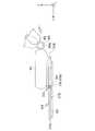
図4は、シート装置300を示す図である。シート装置300は、例えば、着座部301と、背もたれ部302と、足載せ部310とを備える。着座部301の一端と背もたれ部302の下端とは、第1連結部308によって回転自在に連結されている。背もたれ部302の上端には、ヘッドレスト303が設けられている。 FIG. 4 is a diagram illustrating the
着座部301は、乗員の下半身を支持する部材である。着座部301には、乗員が着座する座面301aが形成されている。座面301aは、クッション性の素材で形成されている。着座部301は、床面Fに固定部材304を介して取り付けられている。床面Fと着座部301との間の空間には、足載せ部310が収納自在に設けられている。足載せ部の構成については後に詳述する。着座部301の一端と背もたれ部302の下端とは第1連結部308を介して回転自在に連結されている。 The
背もたれ部302は、乗員の胴部を支持する部材である。背もたれ部302は、背もたれ面302aは、クッション性の素材で形成されている。背もたれ部302の先端にはヘッドレスト303が設けられている。ヘッドレスト303は、着座部301に着座した乗員Dの頭部または首部を支持する。背もたれ部302は、第1連結部308によって、床面Fに対して回転角を付けてリクライニング状態とすることができる。第1連結部308は、例えば回転ヒンジ構造を有する。 The
第1連結部308は、例えば、回転バネ等の付勢手段(不図示)を備え、背もたれ部302と着座部301とのなす角度が狭まる方向(+X方向)に背もたれ部302を付勢している。第1連結部308は、着座部301に設けられたレバー307に連動したロック機構(不図示)を備える。 The first connecting
レバー307を解除すると、背もたれ部302は、第1連結部308の付勢力によって第1連結部308を中心に前方(+X方向)に倒れる。レバー307の解除状態で乗員が背もたれ面302aに後方(−X方向)に力を加えると、背もたれ部302が第1連結部308を中心に後方に倒れる。このようにして乗員は、背もたれ部302のリクライニング角度を調整することができる。第1連結部308の上記構成は機械式を例示したが、第1連結部308は電動で制御されるものであってもよく、ステッピングモータ、アクチュエータ等、角度調整することができればどのような構成のものを用いてもよい。第1連結部308が電動の場合、第1連結部308は、シート制御部160によって制御される。 When the
また、第1連結部308は、着座部301と背もたれ部302とのなす第1角度θ1を検出する第1角度検出部308a(図5参照)を備える。第1角度検出部308aは、シート制御部160に接続されている。例えば着座部301は床面Fと平行に設置されているため、床面Fと背もたれ部302とのなす角度を、第1角度θ1として扱ってもよい。 Moreover, the
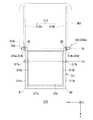
図5は、足載せ部310の構成を示す平面図である。足載せ部310は、いわゆるオットマンである。足載せ部310は、枠体311と、脚支持部312と、レール部313と、第2連結部314とを備える。レール部313は、一対のレール部材313a,313bと、位置検出部313cとを備える。一対のレール部材313a,313bは、着座部301の底面に平行に取り付けられている。 FIG. 5 is a plan view showing the configuration of the
位置検出部313cは、一対のレール部材313a,313bのいずれかの先端(+X方向の先端)に設けられている。本実施形態では、位置検出部313cは、レール部材313aの先端に設けられている構成が例示されているが、少なくとも一方のレール部材313a,313bに位置検出部313cが設けられていればよい。位置検出部313cは、例えばメカニカルスイッチが用いられる。位置検出部313cは、物体の位置が検出できればどのようなものを用いてもよい。 The
位置検出部313cは、枠体311が先端に位置することを検出する。位置検出部313cは、シート制御部160に検出結果を出力する。枠体311は、レール部313の下方にレール部313に対して第2連結部314を介して回転自在に連結されている。 The
第2連結部314は、一対の連結部材314a,314bを備える。第2連結部314は、レール部313に対して摺動自在に取り付けられている。一対の連結部材314a,314bは、それぞれ一対のレール部材313a,313bに取り付けられている。これにより、枠体311は、レール部313に対して前後方向(X軸方向)に摺動自在となる。そして、枠体311は着座部301に対して収納自在となる。 The second connecting
枠体311は、例えばパイプを折り曲げて逆門型形状(矩形の開水路断面形状)に形成されたパイプフレームである。枠体311は、パイプを溶接して形成されていてもよいし、パイプを継手で連結して形成されていてもよい。枠体311は、例えば、一対の縦枠311a,311bと、横枠311cとを備える。一対の縦枠311a,311bは、例えば、進行方向(X軸方向)に沿って対向して平行に配置されている。 The
一対の縦枠311a,311bのそれぞれの先端A1,A2には、先端A同士を連結する横枠311cが設けられている。311c横枠は、乗員のかかとを支持する。横枠311cの位置は、一対の縦枠311a,311bのそれぞれの先端A1,A2以外の位置でもよい。 A
横枠311cは、左右方向(Y軸方向)に沿って配置されている。一対の縦枠311a,311bのそれぞれの基端B1,B2には、第2連結部314の連結部材314a,314bがそれぞれ設けられている。第2連結部314によって、枠体311は、着座部301に対して相対的にY軸方向に沿った回転軸(第1回転軸)Lbを中心に回転する。第2連結部314の連結部材314bには、枠体311を回転駆動する駆動部315が設けられている。駆動部315は、一対の連結部材314a,314bの少なくとも一方に設けられていればよい。駆動部315は、シート制御部160に接続されている。 The
駆動部315には、第2連結部314の回転角度を検出する第2角度検出部315aが設けられている。第2角度検出部315aは、レール部313と枠体311とのなす第2角度θ2を検出する。第2角度検出部315aは、駆動部315と別体で設けられていてもよいし、一体で設けられていてもよい。 The driving
第2角度検出部315aは、シート制御部160に接続されている。第2角度検出部315aは、シート制御部160に第2連結部314の第2角度θ2の検出結果を出力する。シート制御部160は、上記の第1角度検出部308aの検出結果に基づいて駆動部315を制御して第2角度検出部315aを調整する。 The second
第2連結部314の連結部材314aには、枠体311のレール部313に対する摺動をロックするロック機構316が設けられている。駆動部315及びロック機構316は、シート制御部160に接続されると共に、シート制御部160によって制御される(図6参照)。ロック機構316は、シート制御部160により、自動運転時にロックが解除される。即ち、枠体311は、自動運転時に着座部301の下方から出し入れ自在となる。枠体311が着座部301から乗員によって引き出されて、レール部313の先端に位置した場合、位置検出部313cが枠体311を検出し、シート制御部160に検出結果を出力する。 A
シート制御部160は、位置検出部313cの検出結果に基づいて駆動部315の制御を開始する。シート制御部160の制御によって枠体311は、回転軸Lb周りに下方に回転制御される。駆動部315の制御については後述する。 The
枠体311の内側には、脚支持部312が設けられている。脚支持部312は、矩形の板状体であり、枠体311の内側の形状より小さく形成されている。脚支持部312の左右方向(Y軸方向)の側面312a,312bには、一対の回転連結部317a,317bが設けられている。一対の回転連結部317a,317bは、横枠311cの延在方向に沿った回転軸(第2回転軸)Laを中心として脚支持部312を枠体311に対して相対的に回転させる。 A
脚支持部312は、枠体311が着座部301の下に収納されている状態では一対の縦枠311a,311bの延在方向に沿って平行に配置されている。この脚支持部312の位置を初期状態と呼ぶ。 The
一対の回転連結部317a,317bには、例えば、ばね(不図示)により回転軸La周りに脚支持部312が回転する際に、脚支持部312に対して回転軸L2周りに初期状態に戻る方向に付勢力を与える。従って、枠体311が着座部301から引き出された後、脚支持部312が回転軸La周りに所定の角度範囲で回転すると、ばねの付勢力によって脚支持部312は回転軸La周りに与えられた回転方向と反対方向に回転して初期状態に戻る。 For example, when the
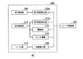
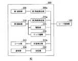
図6は、シート制御システム40の構成を示すブロック図である。シート制御部160は、第1角度検出部308aの検出結果に基づいて、駆動部315を制御して第2角度θ2を調整する。シート制御部160は、例えば、車両Mの運転モードが手動運転から自動運転に切り替わっている場合にシート装置300を制御する。切替制御部142(図1参照)が自動運転の開始予定地点で運転モードを手動運転から自動運転に切り替えると(図3参照)、シート制御部160は、シート装置300の制御を開始する。 FIG. 6 is a block diagram illustrating a configuration of the
このとき、シート制御部160は、HMI30にシート装置300の制御を開始する旨の表示をしてもよい。シート制御部160は、切替制御部142が自動運転の終了予定地点で運転モードを自動運転から手動運転に切り替えた場合、シート装置300を制御して前回の手動運転終了時のシート装置300の状態に戻してもよい。 At this time, the
以下、シート制御部160によるシート装置300の具体的な制御方法について説明する。図7は、リクライニング状態のシート装置300を示す図である。シート制御部160は、車両Mが自動運転に切り替わると第2連結部314のロック機構316を解除し、足載せ部310を出し入れ可能にする。 Hereinafter, a specific control method of the
乗員Dは、自動運転時に背もたれ部302をリクライニング状態にする場合、例えば着座部301の側面に設けられたレバー307を引いたまま第1連結部308のロックを解除する。その後、乗員Dが背もたれ部302を後方(−X方向)押してリクライニング角度を付けて、再びレバー307を戻し、第1連結部308をロックして背もたれ部302をリクライニング状態に保つ。 When the occupant D places the
図8は、足載せ部310が着座部301から引き出された状態を示す図である。例えば、乗員Dが背もたれ部302をリクライニング状態にした後、足載せ部310を引き出す。シート制御部160は、レール部313の位置検出部306の検出結果に基づいて足載せ部310が前方(+X方向)に引き出されたことを認識する。シート制御部160は、駆動部315の制御を開始する。即ち、シート制御部160は、第2連結部314の第2角度θ2を調整開始する。 FIG. 8 is a view showing a state in which the
図9は、角度調整された足載せ部310の状態を示す図である。シート制御部160は、第1角度検出部308aの第1角度θ1の検出結果に基づいて、駆動部315を制御して第1連結部308の第1角度θ1に対して最適な第2連結部314の第2角度θ2を調整する。即ち、シート制御部160は、リクライニングの角度に応じて乗員Dが足を載せやすい状態となるよう足載せ部310の角度を調整する。例えば、リクライニング角度が大きい場合、即ちθ1が小さい場合、第2角度θ2は小さく調整される。 FIG. 9 is a diagram illustrating a state of the
図10は、脚支持部312が回転した状態を示す図である。第2角度θ2が調整された後、乗員Dが脚支持部312に脚部を載置すると、脚支持部312は、乗員が脚部を載置した際に脚部の自重によって回転する。そして乗員の脚部のふくらはぎは、脚支持部312によって支持される。そのとき乗員のかかとは、横枠311cによって支持される。 FIG. 10 is a diagram illustrating a state in which the
上記の調整された足載せ部310の第2角度θ2は、乗員Dが微調整を行ってもよい。その場合、シート制御システム420は、乗員D毎に微調整値を記憶しておき、自動運転時において乗員D毎にシート装置300を調整してもよい。乗員D毎の設定において、シート制御部160は、HMI30により設定情報を受け付けてもよい。また、足載せ部310の制御は乗員Dが任意に選択するものであってもよく、乗員Dが操作を行って動作または解除されるものであってもよい。 The occupant D may finely adjust the second angle θ2 of the adjusted
シート制御部160は、切替制御部142が自動運転の終了予定地点で運転モードを自動運転から手動運転に切り替える前で、駆動部315を制御して第2連結部314の第2角度θ2を制御開始前の状態に戻してもよい。このときシート制御部160は、HMI30にシート装置300の制御を終了し、足載せ部310の収納を促す旨の表示をしてもよい。 The
以下、シート制御部160が制御する処理の流れについて説明する。 Hereinafter, the flow of processing controlled by the
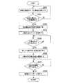
図11は、シート制御部160が行う処理の流れについて説明するフローチャートである。シート制御部160は、切替制御部142から車両Mの運転モードの情報を取得する(ステップS100)。シート制御部160は、切替制御部142からの情報より、車両Mの運転モードが自動運転の場合(ステップS101:Yes)、自動運転時のシート装置300の制御を開始する(ステップS102)。 FIG. 11 is a flowchart for explaining the flow of processing performed by the
シート制御部160は、第2連結部314のロック機構を解除して足載せ部310を着座部301の下側から引き出せるようにする(ステップS103)。シート制御部160は、レール部313の位置検出部306の出力結果に基づいて足載せ部310が引き出されたか否かを判断する(ステップS104)。シート制御部160は、足載せ部310が引き出されたと判断した場合(ステップS104:Yes)、第1連結部308の第1角度検出部308aの出力に基づいて背もたれ部302の第1角度θ1を検出する(ステップS105)。 The
シート制御部160は、第1角度θ1に基づいて第2連結部314の駆動部315を制御して第2角度検出部315aでモニタされる第2角度θ2を調整する(ステップS106)。上記処理で否定的な結果となる場合は、シート制御部160によって所定のステップに戻る処理が行われる。 The
上述したように、第1実施形態のシート制御システム40によると、車両Mの自動運転時に乗員Dがシート装置300をリクライニング状態にした場合、足載せ部310の角度を自動調整して乗員Dの快適な着座姿勢を確保することができる。これにより、シート制御システム40によって自動運転時の乗員Dの快適性を向上させることができる。 As described above, according to the
<第2実施形態>
第1実施形態のシート制御システム40では、車両Mの自動運転時に乗員Dがシート装置300をリクライニング状態にした場合、足載せ部310の角度が自動調整して乗員Dの快適性を向上させた。第2実施形態のシート制御システム42では、足載せ部310に付加機能を加えて、自動運転時の乗員Dの快適性を更に向上させる。Second Embodiment
In the
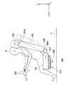
図12は、第2実施形態のシート装置350の構成を示す図である。シート装置350は、シート装置300の構成に対して、例えば袋体部330と、加圧部320とを更に備える。 FIG. 12 is a diagram illustrating a configuration of a
加圧部320は、袋体部330内部を流体fによって加圧する装置である。加圧部320は、例えば空気を送るコンプレッサーである。加圧部320は、例えば着座部301の下方の床面Fに配置されている。加圧部320は、足載せ部310が着座部301の下に収容された状態で邪魔にならないように配置されている。 The pressurizing
加圧部320と縦枠311aの基端B1との間には、可撓性の配管321(例えばエアホース)で接続されている。これにより、加圧部320は、枠体311内部に流体fを流入させて加圧することができる。加圧部320が作動中は、枠体311内部が加圧され、加圧部320が停止すると加圧された流体fが枠体311外部に流出するものとする。加圧部320は、加圧の他、減圧を行ってもよい。加圧部320は、シート制御部160によって制御される。加圧部320の制御については後述する。 Between the
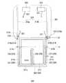
図13は、袋体部330の構成を示す断面図である。袋体部330は、乗員の脚部を挟持するための膨張自在なエアバッグである。袋体部330は、例えば一対の側方袋体331,332と、中央袋体333とを備える。袋体部330の収縮時の形状は、足載せ部310の出し入れに支障が無いように形成されている。 FIG. 13 is a cross-sectional view showing the configuration of the
側方袋体331は、縦枠311aの内側に沿って延在している。同様に側方袋体332は、縦枠311bの内側に沿って延在している。側方袋体331と側方袋体332とは同様の構成のため、代表して側方袋体331について説明する。 The
側方袋体331は、側方袋体331と縦枠311aとの間は、例えば接着剤で接着されることにより密着している。側方袋体331と縦枠311aとの接着部分には、側方袋体331と縦枠311aとの内部を貫通する複数の貫通孔T1が形成されている。貫通孔T1には、縦枠311a内部を流通する流体f(例えば空気)が流入出し、側方袋体331内部が流体によって加圧または減圧される。 The
流体fは液体も用いられ得る。側方袋体331は、流体fが流入して加圧された場合、乗員Dの一方の脚部D3の一側面を側方から押圧する形状に膨張する。側方袋体331は、例えばゴムで形成されている。このとき、側方袋体331は、脚部D3の形状に合わせて弾性変形する。 The fluid f can also be a liquid. When the fluid f flows in and pressurizes, the
次に、中央袋体333について説明する。中央袋体333は、一対の側方袋体331,332の間に設けられている。中央袋体333は、縦枠311a,311bの延在方向に沿って形成されている。中央袋体333の内部には、横枠311cの中央から縦枠311a,311bの延在方向に沿って枠体311の内側に向かって設けられた支柱管311dが設けられている。 Next, the
即ち中央袋体333は、支柱管311dを覆っており、中央袋体333の基端333aは、支柱管311dと気密性を保つように例えば接着剤で接着されている。支柱管311dは、枠体311と同じ材質で形成されている管状部材である。支柱管311dの基端は横枠311cに接続されており、支柱管311dの内部と横枠311cの内部は連通している。支柱管311dには、複数の貫通孔T2が形成されている。 That is, the
貫通孔T2には、支柱管311dからの内部を流通する流体f(例えば空気)が流入出し、中央袋体333内部が流体によって加圧または減圧される。中央袋体333は、流体fが流入して加圧された場合、乗員Dの一対の脚部D3,D4の間から脚部D3,D4の対向する面をそれぞれ押圧する形状に膨張する。側方袋体331は、例えばゴムで形成されている。このとき、中央袋体333は、脚部D3,D4の形状に合わせて弾性変形する。 The fluid f (for example, air) flowing through the inside of the
これにより、一対の側方袋体331,332と、中央袋体333とによって、袋体部330の膨張時に乗員Dの脚部D3,D4が挟持される。 Accordingly, the leg portions D3 and D4 of the occupant D are held by the pair of
図14は、第2実施形態のシート制御システム42の構成を示すブロック図である。シート制御システム42は、第1実施形態のシート制御システム40の構成に対して袋体部330を膨張制御するための加圧部320を更に備える。加圧部320は、シート制御部160によって制御され、袋体部330内部に流体fを送って加圧状態として袋体部330を膨張させる。 FIG. 14 is a block diagram illustrating a configuration of the
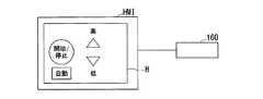
シート制御部160は、加圧部320を制御することにより、袋体部330の膨張度合いに経時的な変化を与える。即ち、シート制御部160は、袋体部330を用いて乗員Dの脚部D3,D4にマッサージを与えることができる。加圧部320の制御態様は、例えばHMI30に表示される選択画面Gを介して乗員Dによって変更されてもよい。図15は、HMI30に表示される選択画面Gを示す図である。 The
次に、シート制御システム42のシート制御部160が制御する処理の流れについて説明する。図16は、シート制御部160が行う処理の流れについて説明するフローチャートである。ステップS200からステップS206までは第1実施形態と同一である。ここでは、ステップS207とステップS208とが追加されている。以下、第1実施形態と同じ処理については説明を適宜省略する。 Next, the flow of processing controlled by the
シート制御部160は、足載せ部310の第2角度θ2を調整した後(ステップS206)、HMI30に表示される選択画面Gを介して加圧部320に対する操作が行われたか否かを判定する(ステップS207)。シート制御部160は、加圧部320に対する操作が行われた場合(ステップS207:Yes)、選択画面Gで選択された操作に基づいて加圧部320の制御態様を変更し、乗員Dの脚部D3,D4のマッサージを行う(ステップS208)。 After adjusting the second angle θ2 of the footrest unit 310 (step S206), the
上述したように第2実施形態のシート制御システム42によると、自動運転時に乗員Dが引き出した足載せ部310の加圧部320を制御することで、自動運転時の快適性を向上させることができる。 As described above, according to the
<第3実施形態>
第2実施形態のシート制御システム42では、加圧部320を制御することで、マッサージを行い自動運転時の快適性を向上させた。第3実施形態に係るでは、袋体部330に温度変化を与えることで乗員Dに更なる快適性を与えるシート制御システム44を例示する。<Third Embodiment>
In the
図17は、第3実施形態にかかるシート装置380の構成を示す図である。シート装置350は、例えば第2実施形態のシート装置350に対して熱源部375と、熱源制御部370とを更に備える。熱源部375は、例えばニクロム線で構成されたヒータである。熱源部375は、縦枠311a内に設けられた第1ヒータ376と、縦枠311b内に設けられた第2ヒータ377と、支柱管311d内に設けられた第3ヒータ378とを備える。 FIG. 17 is a diagram illustrating a configuration of a
熱源部375は、ニクロム線の他、例えば電磁コイルで金属製の枠体311に渦電流を生じさせて熱を発生させるものであってもよい。但し、熱源部375は、枠体311内の流体fの流れを妨げにくい形状のものが用いられる。 The
熱源部375は、配線371を介して熱源制御部370に接続されている。熱源部375は、熱源制御部370によって温度調整される。熱源制御部370は、熱源部375を温度調整するための制御回路を備え、シート制御部160によって制御される。熱源制御部370は、例えば着座部301の下方の床面Fに配置される。The
熱源部375の温度は、例えばHMI30に表示される操作画面を介して乗員Dによって変更されてもよい。図18は、熱源部375の温度調整をするためにHMI30に表示される操作画面Hを示す図である。また、熱源部375の温度は、シート制御部160によって自動制御されてもよい。この他、熱源部375は、熱源制御部370に設けられたメカニカルスイッチで乗員Dによって任意に温度調整されてもよい。 For example, the temperature of the
図19は、第3実施形態にかかるシート制御システム44の構成を示すブロック図である。シート制御システム44の構成は、第2実施形態のシート制御システム42の構成に対して熱源部375と、熱源制御部370とが追加されている。 FIG. 19 is a block diagram illustrating a configuration of a
シート制御部160は、加圧部320を制御して袋体部330を膨張した後、HMI30に温度調整をするための操作画面Hを表示させる。シート制御部160は、乗員Dが行った操作画面Hの操作に基づいて熱源制御部370を制御して熱源部375の温度を変更する。これにより袋体部330の内部の流体fの温度が変化し、乗員Dの快適性が向上する。
図20は、シート制御部160が行う処理の流れについて説明するフローチャートである。ステップS300からステップS308までは第2実施形態と同一である。ここでは、ステップS309とステップS310とが追加されている。以下、第2実施形態と同じ処理については説明を適宜省略する。The
FIG. 20 is a flowchart illustrating the flow of processing performed by the
シート制御部160は、袋体部330の制御を行った後(ステップS308)、HMI30に表示される操作画面Hを介して熱源部375に対する操作が行われたか否かを判定する(ステップS309)。シート制御部160は、熱源部375に対する操作が行われた場合(ステップS309:Yes)、操作画面Hで選択された操作に基づいて熱源制御部370を制御して熱源部375の温度調整を行い、袋体部330の温度を調整する(ステップS310)。 After controlling the bag body 330 (step S308), the
上述した第3実施形態のシート制御システム44によると、袋体部330の温度を調整することができ、乗員Dの快適性を向上させることができる。 According to the
以上説明した実施形態におけるシート車両シート制御システム、車両シート制御方法、および車両シート制御プログラムによれば、車両Mが自動運転中に乗員Dがシートをリクライニング状態にした場合、足載せ部310に関する制御を行うことで乗員Dの快適性を向上することができる。 According to the seat vehicle seat control system, the vehicle seat control method, and the vehicle seat control program in the embodiment described above, when the vehicle D is in the reclining state while the vehicle M is in automatic operation, the control related to the
以上、本発明を実施するための形態について実施形態を用いて説明したが、本発明はこうした実施形態に何等限定されるものではなく、本発明の要旨を逸脱しない範囲内において種々の変形及び置換を加えることができる。例えば、上記実施形態では枠体311に袋体部330を設ける場合を例示したが、これに限らず、袋体部は脚支持部312上に設けられていてもよい。 As mentioned above, although the form for implementing this invention was demonstrated using embodiment, this invention is not limited to such embodiment at all, In the range which does not deviate from the summary of this invention, various deformation | transformation and substitution Can be added. For example, although the case where the
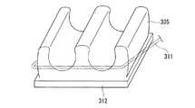
図21は、袋体の変形例を示す図である。図示するように、袋体部335は脚支持部312上に設けられている。この場合、袋体部335は、膨張時に乗員Dの脚部を挟持する形状に形成される。そして袋体部335は、収縮時には、足載せ部310の出し入れに支障が出ない形状に戻る。これにより、袋体部335の構成を簡略化することができる。 FIG. 21 is a diagram showing a modification of the bag. As shown in the figure, the
その他、上記実施形態では、足載せ部310は、自動運転時にはロック機構316によって着座部301から取り出せないようになっていた。しかし、席が運転席以外である場合には、この限りでなく、手動運転時にも足載せ部310を取り出して使用できるようにしてもよい。 In addition, in the above embodiment, the
1…車両システム、10…カメラ、12…レーダ装置、14…ファインダ、16…物体認識装置、20…通信装置、40…シート制御システム、42…シート制御システム、44…シート制御システム、50…ナビゲーション装置、51…(Global…Navigation…Satellite…System)受信機、51…受信機、53…経路決定部、54…第1地図情報、61…推奨車線決定部、62…第2地図情報、70…車両センサ、80…運転操作子、90…車室内カメラ、100…自動運転制御ユニット、120…第1制御部、121…外界認識部、122…自車位置認識部、123…行動計画生成部、140…第2制御部、141…走行制御部、142…切替制御部、150…インターフェース制御部、160…シート制御部、170…物体判定部、180…挙動取得部、200…走行駆動力出力装置、210…ブレーキ装置、220…ステアリング装置、300…シート装置、301…着座部、301a…座面、302…背もたれ部、302a…背もたれ面、303…ヘッドレスト、304…固定部材、306…位置検出部、307…レバー、308…第1連結部、308a…第1角度検出部、310…足載せ部、311…枠体、311a…縦枠、311b…縦枠、311c…横枠、311d…支柱管、312…脚支持部、313…レール部、313a…レール部材、313b…レール部材、313c…位置検出部、314…第2連結部、314a…連結部材、314b…連結部材、315…駆動部、315a…第2角度検出部、316…ロック機構、317a…回転連結部、317b…回転連結部、320…加圧部、321…配管、330…袋体部、331…側方袋体、332…側方袋体、333…中央袋体、335…袋体部、350…シート装置、370…熱源制御部、371…配線、375…熱源部、376…第1ヒータ、377…第2ヒータ、378…第3ヒータ、380…シート装置、420…シート制御システム、f…流体、F…床面、G…選択画面、H…操作画面、HMI52…ナビ、M…車両、T1…貫通孔、T2…貫通孔DESCRIPTION OF
Claims (8)
Translated fromJapanese一対の縦枠と、前記一対の縦枠同士を連結する横枠とを備え、前記座面部に収納自在に設けられた枠体と、
前記横枠の延在方向に平行な第1回転軸を有し、前記枠体の内側に前記枠体に対して回転自在に設けられた脚支持部と、
前記一対の縦枠の少なくとも一方の基端に設けられ、前記座面部から出された状態の前記枠体を前記横枠の延在方向に平行な第2回転軸周りに回転させる駆動部と、
車両の少なくとも自動運転時に、前記角度検出部の検出結果に基づいて前記駆動部を制御する制御部と、を備える、
車両シート制御システム。An angle detection unit that detects an angle of a connecting part that rotatably connects the seat surface part and the backrest part; and
A frame provided with a pair of vertical frames and a horizontal frame connecting the pair of vertical frames, the frame body being storable in the seat surface portion;
A leg support portion having a first rotation axis parallel to the extending direction of the horizontal frame, and provided rotatably inside the frame body with respect to the frame body;
A drive unit that is provided at at least one base end of the pair of vertical frames and rotates the frame in a state of being protruded from the seating surface unit around a second rotation axis parallel to the extending direction of the horizontal frame;
A control unit that controls the drive unit based on a detection result of the angle detection unit at least during automatic driving of the vehicle,
Vehicle seat control system.
前記袋体部を流体によって膨張させる加圧部と、を更に備え、
前記制御部は、前記車両の自動運転時に前記加圧部を作動させる、
請求項1に記載の車両シート制御システム。A bag body part that is attached to either the inside of the frame body or the upper surface of the leg support part, and is inflatable into a shape that sandwiches the legs of the occupant,
A pressurizing part for inflating the bag body part with a fluid,
The control unit operates the pressurizing unit during automatic driving of the vehicle.
The vehicle seat control system according to claim 1.
請求項2に記載の車両シート制御システム。The frame body is formed of a tubular member, and the fluid flows into the bag body portion through the inside of the tubular member.
The vehicle seat control system according to claim 2.
請求項2または3に記載の車両シート制御システム。The control unit changes a control mode of the pressurizing unit based on an operation of the occupant.
The vehicle seat control system according to claim 2 or 3.
前記制御部は、前記検出部の検出結果に基づいて前記駆動部及び前記加圧部の制御を開始する、
請求項2から4のいずれか1項に記載の車両シート制御システム。A detection unit for detecting that the frame body has been taken in and out from the seat surface part;
The control unit starts control of the drive unit and the pressurizing unit based on a detection result of the detection unit.
The vehicle seat control system according to any one of claims 2 to 4.
前記制御部は、乗員の操作に基づいて前記熱源部を制御して前記袋体部に温度変化を与える、
請求項2から5のいずれか1項に記載の車両シート制御システム。It further comprises a heat source part that gives a temperature change to the bag part,
The control unit controls the heat source unit based on an operation of an occupant to give a temperature change to the bag body unit,
The vehicle seat control system according to any one of claims 2 to 5.
コンピュータに、
前記座面部と背もたれ部とを回転自在に連結する連結部の角度を検出させ、
車両の少なくとも自動運転時に、検出結果に基づいて前記駆動部を制御させる、
車両シートの制御方法。A frame having a pair of vertical frames and a horizontal frame connecting the pair of vertical frames, and having a frame body that can be stored in a seating surface portion, and a first rotation axis parallel to the extending direction of the horizontal frame. The frame is in a state where it is provided at a base end of at least one of the pair of vertical frames and protruded from the seat surface portion, and is provided on the inner side of the frame so as to be rotatable with respect to the frame. A vehicle seat control method comprising: a drive unit that rotates a body around a second rotation axis parallel to an extending direction of the horizontal frame,
On the computer,
Detecting the angle of the connecting portion that rotatably connects the seat surface portion and the backrest portion;
Controlling the drive unit based on a detection result at least during automatic driving of the vehicle;
Vehicle seat control method.
コンピュータが、
前記座面部と背もたれ部とを回転自在に連結する連結部の角度を検出し、
車両の少なくとも自動運転時に、検出結果に基づいて前記駆動部を制御する、
プログラム。A frame having a pair of vertical frames and a horizontal frame connecting the pair of vertical frames, and having a frame body that can be stored in a seating surface portion, and a first rotation axis parallel to the extending direction of the horizontal frame. The frame is in a state where it is provided at a base end of at least one of the pair of vertical frames and protruded from the seat surface portion, and is provided on the inner side of the frame so as to be rotatable with respect to the frame. A vehicle seat control program comprising: a drive unit that rotates a body around a second rotation axis parallel to the extending direction of the horizontal frame;
Computer
Detecting the angle of the connecting portion for rotatably connecting the seat surface portion and the backrest portion;
Controlling the drive unit based on a detection result at least during automatic driving of the vehicle;
program.
Priority Applications (3)
| Application Number | Priority Date | Filing Date | Title |
|---|---|---|---|
| JP2017023192AJP6421365B2 (en) | 2017-02-10 | 2017-02-10 | Vehicle seat control system, vehicle seat control method, and program |
| CN201810104009.5ACN108407675B (en) | 2017-02-10 | 2018-02-01 | Vehicle seat control system, control method of vehicle seat, and storage medium |
| US15/886,866US10889224B2 (en) | 2017-02-10 | 2018-02-02 | Vehicle seat control system, vehicle seat control method, and storage medium |
Applications Claiming Priority (1)
| Application Number | Priority Date | Filing Date | Title |
|---|---|---|---|
| JP2017023192AJP6421365B2 (en) | 2017-02-10 | 2017-02-10 | Vehicle seat control system, vehicle seat control method, and program |
Publications (2)
| Publication Number | Publication Date |
|---|---|
| JP2018127169A JP2018127169A (en) | 2018-08-16 |
| JP6421365B2true JP6421365B2 (en) | 2018-11-14 |
Family
ID=63106736
Family Applications (1)
| Application Number | Title | Priority Date | Filing Date |
|---|---|---|---|
| JP2017023192AExpired - Fee RelatedJP6421365B2 (en) | 2017-02-10 | 2017-02-10 | Vehicle seat control system, vehicle seat control method, and program |
Country Status (3)
| Country | Link |
|---|---|
| US (1) | US10889224B2 (en) |
| JP (1) | JP6421365B2 (en) |
| CN (1) | CN108407675B (en) |
Families Citing this family (10)
| Publication number | Priority date | Publication date | Assignee | Title |
|---|---|---|---|---|
| JP2018197089A (en)* | 2017-05-25 | 2018-12-13 | トヨタ紡織株式会社 | Footrest device for vehicle |
| JP7092045B2 (en)* | 2019-01-16 | 2022-06-28 | トヨタ自動車株式会社 | Vehicle interior control device |
| DE112020001663T5 (en)* | 2019-03-29 | 2022-03-24 | Intel Corporation | Autonomous Vehicle System |
| JP7135988B2 (en)* | 2019-04-22 | 2022-09-13 | トヨタ紡織株式会社 | Wiring harness routing structure for heater for ottoman with telescopic function |
| CN110380386B (en)* | 2019-06-14 | 2021-06-08 | 浙江零跑科技有限公司 | Electric seat controller with protection function and control method thereof |
| CN110920497A (en)* | 2019-12-09 | 2020-03-27 | 东风汽车有限公司 | Automobile seat leg drag adjusting method and electronic equipment |
| US11400846B2 (en)* | 2020-01-07 | 2022-08-02 | The Braun Corporation | Foot rest assembly for a seat of a motorized vehicle |
| CN111674308A (en)* | 2020-05-07 | 2020-09-18 | 宁波舜宇精工股份有限公司 | Pedal mechanism and vehicle provided with same |
| CN112092686A (en)* | 2020-08-20 | 2020-12-18 | 艾福迈汽车系统(上海)有限公司 | Adaptive seat comfort system based on fit of passenger and seat and adjusting method |
| CN112158113B (en)* | 2020-10-27 | 2021-08-31 | 杭州职业技术学院 | A leg support structure for a car seat |
Family Cites Families (118)
| Publication number | Priority date | Publication date | Assignee | Title |
|---|---|---|---|---|
| US1951793A (en)* | 1932-02-27 | 1934-03-20 | Lewis X Herman | Chair device |
| US2174622A (en)* | 1937-06-24 | 1939-10-03 | Glenn L Martin Co | Aircraft furniture |
| US2484803A (en)* | 1945-09-29 | 1949-10-18 | Heywood Wakefield Co | Retractile leg rest |
| NL91234C (en)* | 1954-07-08 | |||
| US3007738A (en)* | 1958-12-16 | 1961-11-07 | Gardel Robert | Extension leg rest for chairs and the like |
| US3794381A (en)* | 1971-10-26 | 1974-02-26 | D Caldemeyer | Footrest for reclining chair |
| US4358156A (en)* | 1980-03-28 | 1982-11-09 | Sharff Harold M | Foot rest and actuator for chairs for patients and invalids |
| FR2501486B1 (en)* | 1981-03-16 | 1985-10-18 | Air France | LEG SUPPORT, ESPECIALLY FOR TRANSPORT VEHICLES AND ESPECIALLY FOR AIRCRAFT |
| JPS6036339A (en) | 1983-06-06 | 1985-02-25 | ボリス・エル・ルドイ | Glass product continuous manufacture device |
| JPS6036339U (en)* | 1983-08-19 | 1985-03-13 | 株式会社タチエス | relaxation sheet |
| JPS61157040U (en)* | 1985-03-23 | 1986-09-29 | ||
| US5098158A (en)* | 1989-08-17 | 1992-03-24 | Palarski Timothy D | Articulated relaxation chair |
| JPH0492445A (en) | 1990-08-07 | 1992-03-25 | Seiko Epson Corp | semiconductor equipment |
| JPH0492445U (en)* | 1990-12-28 | 1992-08-12 | ||
| US5082324A (en)* | 1991-04-16 | 1992-01-21 | Ben Company Ltd. | Foldable reclining chair |
| US5333818A (en)* | 1993-07-19 | 1994-08-02 | Erda, Inc. | Aircraft berthing seat |
| US5560681A (en)* | 1995-03-21 | 1996-10-01 | Burns Aerospace Corporation | Seat bottom extension mechanism for passenger seats |
| US5651587A (en)* | 1995-06-09 | 1997-07-29 | P.L. Porter Co. | Vehicle seat and system for controlling the same |
| JP3086785B2 (en)* | 1996-12-04 | 2000-09-11 | 小糸工業株式会社 | Vehicle seating equipment |
| JPH10229931A (en)* | 1996-12-19 | 1998-09-02 | Araco Corp | Child chair |
| US6212719B1 (en)* | 1997-10-10 | 2001-04-10 | D2Rm Corp. | Air massager cushioning device |
| JP3323989B2 (en)* | 1998-05-28 | 2002-09-09 | ジョンソン コントロールズ オートモーティブ システムズ株式会社 | Electric ottoman device |
| JP3593888B2 (en) | 1998-07-13 | 2004-11-24 | トヨタ車体株式会社 | Seat mechanism |
| US6161663A (en)* | 1998-08-07 | 2000-12-19 | Enidine, Incorporated | Stroke limiting velocity sensitive valve for a hydraulic lock mechanism |
| US6237994B1 (en)* | 1999-06-11 | 2001-05-29 | Weber Aircraft, Inc. | Multi-function seats |
| EP1116653B1 (en)* | 2000-01-14 | 2006-03-15 | Be Aerospace, Inc. | Passenger seat with fabric suspension legrest |
| EP1116652B1 (en)* | 2000-01-14 | 2006-03-15 | Be Aerospace, Inc. | Passenger seat with variable length seat bottom |
| DE10003407A1 (en)* | 2000-01-27 | 2001-08-09 | Recaro Aircraft Seating Gmbh | Vehicle seat for aircraft or motor vehicles |
| FR2808433B1 (en)* | 2000-05-04 | 2002-08-02 | Labinal | METHOD FOR MANAGING THE KINEMATICS OF A SEAT WITH PRE-PROGRAMMED POSITIONS AND SEAT USING THE SAME |
| FR2810930B1 (en)* | 2000-06-29 | 2002-11-29 | Labinal | METHOD FOR MANAGING THE KINEMATICS OF A MOBILE SEAT |
| FR2811272B1 (en)* | 2000-07-05 | 2002-09-27 | Sicma Aero Seat | AIRPLANE SEAT WITH LEG-BASED ADJUSTMENT AND ADJUSTABLE LEGS |
| DE50014680D1 (en)* | 2000-08-25 | 2007-11-08 | Recaro Aircraft Seating Gmbh | SEAT FOR PASSENGER TRANSPORT, IN PARTICULAR PASSENGER SEAT |
| US6588837B1 (en)* | 2000-11-01 | 2003-07-08 | Hill-Rom Services, Inc. | Chair with pull out sleep surface |
| US6382727B1 (en)* | 2000-12-18 | 2002-05-07 | Peter B. Pickard | Foldable chair |
| US6439636B1 (en)* | 2001-02-07 | 2002-08-27 | Ming C. Kuo | Vehicle electric reclining seats |
| JP2002240616A (en)* | 2001-02-15 | 2002-08-28 | Minebea Co Ltd | Footrest device for vehicular seat |
| JP2002238695A (en)* | 2001-02-15 | 2002-08-27 | Minebea Co Ltd | Footrest device of sheet for vehicle |
| JP2002240598A (en)* | 2001-02-21 | 2002-08-28 | Minebea Co Ltd | Electrically operated seat for vehicle and its adjusting method |
| JP2002238698A (en)* | 2001-02-22 | 2002-08-27 | Minebea Co Ltd | Seat |
| JP2002248971A (en)* | 2001-02-22 | 2002-09-03 | Minebea Co Ltd | Motorized seat |
| FR2821252B1 (en)* | 2001-02-27 | 2003-12-12 | Labinal | SEAT WITH MOBILE PARTS |
| DE20106560U1 (en)* | 2001-04-14 | 2002-08-29 | Dewert Antriebs- und Systemtechnik GmbH & Co KG, 32278 Kirchlengern | Seat-recliner armchair adjustable by motor |
| JP3086785U (en) | 2001-12-18 | 2002-07-05 | 嘉雄 巫 | Anima fir ball |
| DE10209234B4 (en)* | 2002-03-04 | 2005-06-09 | Daimlerchrysler Ag | Vehicle seat with lower leg support |
| DE10209185C1 (en)* | 2002-03-04 | 2003-06-26 | Daimler Chrysler Ag | Automobile passenger seat with leg support adjusted between stowed position fitting below seat squab and extended working position |
| DE10209186B4 (en)* | 2002-03-04 | 2007-10-18 | Daimlerchrysler Ag | Vehicle seat with footrest |
| FR2838085B1 (en)* | 2002-04-08 | 2004-07-16 | Sicma Aero Seat | SEAT WITH MECHANICAL SYNCHRONIZATION OF THE LEG BACK AND REST |
| US6916069B2 (en)* | 2002-05-07 | 2005-07-12 | Recaro Aircraft Seating Gmbh & Co. | Seat |
| US6805322B2 (en)* | 2002-08-15 | 2004-10-19 | The Boeing Company | Multiple-position seat |
| US6799805B2 (en)* | 2002-11-27 | 2004-10-05 | Be Aerospace, Inc. | Single beam aircraft passenger seat |
| DE102004025507A1 (en)* | 2004-05-21 | 2005-12-15 | Johnson Controls Gmbh Automotive Systems Group | vehicle seat |
| DE202005000574U1 (en)* | 2005-01-14 | 2006-05-24 | Deon Ag | armchair |
| US20080272629A1 (en)* | 2005-02-22 | 2008-11-06 | Walkingshaw Nathan R | Folding Chair Cot for Use with Emergency Vehicles |
| JP4635835B2 (en)* | 2005-11-10 | 2011-02-23 | アイシン精機株式会社 | Electric telescopic device for vehicle seat |
| US7108329B1 (en)* | 2005-11-15 | 2006-09-19 | Robert Clough | Seating unit with retractable footrest |
| DE202006005981U1 (en)* | 2006-04-12 | 2006-06-08 | Isringhausen Gmbh & Co. Kg | Swivel mounted footrest for car seat, comprising lowered axle for perfect position of lower legs |
| DE102006038736B4 (en)* | 2006-08-19 | 2008-09-04 | Kintec-Solution Gmbh | armchair |
| US7546215B2 (en)* | 2007-04-14 | 2009-06-09 | Crane Co. | Method for calibrating a powered seat |
| US7621599B2 (en)* | 2007-09-04 | 2009-11-24 | Honda Motor Co., Ltd | Vehicle seat having an integral, retractable step |
| US20090088930A1 (en)* | 2007-10-02 | 2009-04-02 | Mazda Motor Corporation | Driving posture adjusting apparatus |
| DE102007053119A1 (en)* | 2007-11-08 | 2009-05-14 | Bayerische Motoren Werke Aktiengesellschaft | Method and device for adjusting a seat and seat |
| JP2009292405A (en)* | 2008-06-09 | 2009-12-17 | Toyota Boshoku Corp | Vehicular seat |
| US8070219B2 (en)* | 2008-10-23 | 2011-12-06 | L&P Property Management Company | Chair leg rest assembly |
| DE102008057861B4 (en)* | 2008-11-18 | 2010-09-16 | Continental Automotive Gmbh | Method for automatic seat adjustment and its application |
| US8444226B2 (en)* | 2009-03-30 | 2013-05-21 | Zodiac Seats Us Llc | Leg-rests for passenger seats |
| EP2414233B1 (en)* | 2009-04-03 | 2013-07-31 | BE Aerospace, Inc. | Passenger seat with single actuator seat mechanism |
| FR2948612B1 (en)* | 2009-07-31 | 2011-08-26 | Precilec | METHOD FOR MANAGING THE CINEMATICS OF A SEAT WITH MOBILE PARTS BY SPACE OF FREEDOM AND SEAT USING THE SAME |
| WO2011061711A1 (en)* | 2009-11-19 | 2011-05-26 | Air New Zealand Limited | Method and system for reserving and allocating vehicle seating |
| EP2531403B1 (en)* | 2010-02-02 | 2015-08-05 | BE Aerospace, Inc. | Deployable legrest |
| US8408646B2 (en)* | 2010-04-08 | 2013-04-02 | Ford Global Technologies, Llc | Seat cushion extension mechanism |
| US10543764B2 (en)* | 2010-10-01 | 2020-01-28 | Nissan Motor Co., Ltd. | Vehicle seat and stiffness setting method for vehicle seat |
| US10238566B2 (en)* | 2010-12-08 | 2019-03-26 | Hill-Rom Services, Inc. | Mattress bladder boosting during chair egress |
| IT1403161B1 (en)* | 2010-12-14 | 2013-10-04 | Autostudi S R L | TRANSFORMABLE ARMCHAIR IN CHAISE LONGUE |
| CN105361488B (en)* | 2011-03-30 | 2018-09-07 | 美国皮革制品经营有限责任公司 | Chair and furniture |
| US20120286544A1 (en)* | 2011-05-12 | 2012-11-15 | Warren Cohen | Collapsible Lounge Chair with Backpack Straps |
| WO2012157321A1 (en)* | 2011-05-19 | 2012-11-22 | 日産自動車株式会社 | Seat |
| CN202234113U (en)* | 2011-08-17 | 2012-05-30 | 李宛豫 | Flip footrest |
| KR20130002526U (en)* | 2011-10-19 | 2013-04-29 | (주) 엑토 | Officerecliner |
| US8944498B2 (en)* | 2012-01-05 | 2015-02-03 | L & Property Management Company | Linkage mechanism for a dual-motor lifting recliner |
| EP2825422A4 (en)* | 2012-01-31 | 2016-10-19 | Rajasingham Arjuna Indraeswaran | SUPPORT FOR OCCUPANTS OF A VEHICLE |
| JP5884640B2 (en)* | 2012-05-28 | 2016-03-15 | トヨタ紡織株式会社 | Vehicle seat |
| KR101381575B1 (en)* | 2012-09-06 | 2014-04-07 | 현대다이모스(주) | Seat for vehicle |
| CA2904874C (en)* | 2013-04-04 | 2018-01-09 | B/E Aerospace, Inc. | Passenger seat with drop-down armrest assembly |
| MX345580B (en)* | 2013-07-23 | 2017-02-07 | Nissan Motor | Vehicular drive assist device, and vehicular drive assist method. |
| KR101422820B1 (en)* | 2013-08-06 | 2014-08-01 | 포레시아오토모티브시팅코리아 유한회사 | Apparatus for adjusting length of seat cushion for vehicle |
| US20150084394A1 (en)* | 2013-09-23 | 2015-03-26 | Keith Dwayne Hempstead | Portable seat cushion with extending footrest |
| CA2927634C (en)* | 2013-10-21 | 2018-08-14 | B/E Aerospace, Inc. | Linearly deployable aircraft seat legrest |
| GB2520350B (en)* | 2013-11-19 | 2017-03-08 | Jaguar Land Rover Ltd | Deployable leg rest assembly |
| WO2015153902A1 (en)* | 2014-04-03 | 2015-10-08 | Zodiac Seats Us Llc | Integrated deployable leg rest for reclining passenger seats |
| US9481466B2 (en)* | 2014-06-26 | 2016-11-01 | Itt Manufacturing Enterprises Llc | Powered seat and control thereof |
| EP2974961B1 (en)* | 2014-07-15 | 2017-04-26 | Airbus Defence and Space GmbH | Seat assembly, seat arrangement and passenger cabin for an aircraft |
| FR3025759B1 (en)* | 2014-09-17 | 2016-12-09 | Sogerma | MULTI-POSITION SEAT FOR DRIVING OPERATOR |
| EP3000651B1 (en)* | 2014-09-24 | 2018-02-21 | Volvo Car Corporation | A system and method for seat retraction during an autonomous driving mode |
| US9357847B2 (en)* | 2014-09-26 | 2016-06-07 | Ultra-Mek, Inc. | Reclining seating unit with power actuators |
| US9155394B1 (en)* | 2014-10-03 | 2015-10-13 | Joshua Cohen | Chair with slide-out leg rest |
| JP2016120174A (en)* | 2014-12-25 | 2016-07-07 | 株式会社馬場家具 | Foot mount device and seating tool comprising the same |
| DE102015206501A1 (en)* | 2015-04-13 | 2016-10-13 | Bayerische Motoren Werke Aktiengesellschaft | Method for operating a vehicle and vehicle |
| DE102015107988A1 (en)* | 2015-05-20 | 2016-11-24 | Recaro Aircraft Seating Gmbh & Co. Kg | Passenger seating device |
| EP3153346B1 (en)* | 2015-10-07 | 2019-09-25 | Volvo Car Corporation | A seat system for autonomous vehicles |
| JP2017136898A (en)* | 2016-02-02 | 2017-08-10 | 株式会社Subaru | Vehicle seat control device |
| KR102531815B1 (en)* | 2016-03-11 | 2023-05-16 | 이노텍 모션 게엠베하 | Seating Furniture Chassis with Retractable and Extendable Foot Supports |
| KR101738062B1 (en)* | 2016-05-09 | 2017-05-19 | 현대자동차주식회사 | Structure of leg-rest |
| KR101818357B1 (en)* | 2016-07-19 | 2018-01-12 | 현대다이모스(주) | Apparatus and method for controlling regsupport of vehicle back seat |
| US10093200B2 (en)* | 2016-10-18 | 2018-10-09 | Ford Global Technologies, Llc | Reconfigurable seating assembly |
| US10220754B2 (en)* | 2016-10-18 | 2019-03-05 | Ford Global Technologies, Llc | Inflatable member |
| US10059455B2 (en)* | 2016-10-26 | 2018-08-28 | Ami Industries, Inc. | Cabin attendant seat legrest with an extendable footrest |
| GB2557936B (en)* | 2016-12-19 | 2019-06-12 | Thompson Aero Seating Ltd | Deployable foot rest assembly |
| US11077782B2 (en)* | 2016-12-27 | 2021-08-03 | Adient Engineering and IP GmbH | Vehicle seat with extendable and retractable ottoman |
| JP6421364B2 (en)* | 2017-02-07 | 2018-11-14 | 本田技研工業株式会社 | Vehicle seat control system, vehicle seat control method, and vehicle seat control program |
| JP6464495B2 (en)* | 2017-02-10 | 2019-02-06 | 本田技研工業株式会社 | Vehicle system, vehicle control method, and vehicle control program |
| US10065535B1 (en)* | 2017-03-02 | 2018-09-04 | Ford Global Technologies, Llc | Seatback lift mechanism for a supine motor vehicle seating assembly |
| US10081270B1 (en)* | 2017-03-03 | 2018-09-25 | Ford Global Technologies, Llc | Front seat sleeper seat and features |
| KR101924179B1 (en)* | 2017-04-20 | 2019-02-22 | 대원산업 주식회사 | Leg-rest for vehicle |
| GB2563003B (en)* | 2017-05-23 | 2019-10-02 | Ford Global Tech Llc | A Deployable footrest |
| KR102410521B1 (en)* | 2017-12-06 | 2022-06-20 | 현대자동차주식회사 | Relax seat belt for vehicle |
| US10232740B1 (en)* | 2018-03-06 | 2019-03-19 | Ford Global Technologies, Llc | Adjustable seatback recline angle and warning system |
| US10869555B2 (en)* | 2018-07-09 | 2020-12-22 | Marshea Jones | Motorized chair assembly |
| JP7225812B2 (en)* | 2019-01-16 | 2023-02-21 | トヨタ紡織株式会社 | vehicle seat |
- 2017
- 2017-02-10JPJP2017023192Apatent/JP6421365B2/ennot_activeExpired - Fee Related
- 2018
- 2018-02-01CNCN201810104009.5Apatent/CN108407675B/ennot_activeExpired - Fee Related
- 2018-02-02USUS15/886,866patent/US10889224B2/ennot_activeExpired - Fee Related
Also Published As
| Publication number | Publication date |
|---|---|
| CN108407675A (en) | 2018-08-17 |
| JP2018127169A (en) | 2018-08-16 |
| US20180229638A1 (en) | 2018-08-16 |
| CN108407675B (en) | 2020-04-07 |
| US10889224B2 (en) | 2021-01-12 |
Similar Documents
| Publication | Publication Date | Title |
|---|---|---|
| JP6421365B2 (en) | Vehicle seat control system, vehicle seat control method, and program | |
| CN109703561B (en) | Vehicle operating system, vehicle operating method and storage medium | |
| JP6464496B2 (en) | Vehicle seat device | |
| JP6421364B2 (en) | Vehicle seat control system, vehicle seat control method, and vehicle seat control program | |
| CN108382271B (en) | Vehicle system, vehicle control method, and storage medium | |
| JP6496944B2 (en) | Vehicle seat device | |
| CN107415957A (en) | Vehicle control system, control method for vehicle and wagon control program | |
| CN108327592B (en) | Vehicle control system, vehicle control method, and storage medium | |
| JPWO2018173161A1 (en) | Crew restraint structure | |
| JP2018176902A (en) | Vehicle control system, vehicle control method, and vehicle control program | |
| JPWO2018185931A1 (en) | Vehicle control system, vehicle control method, and program | |
| JP2018090057A (en) | Occupant holding device | |
| JP2018127136A (en) | Vehicle seat device | |
| CN110382304B (en) | Passenger restraint structure | |
| JP6458815B2 (en) | Vehicle seat device | |
| JP2018108746A (en) | Vehicle control device | |
| CN108569244A (en) | The non-transitory storage medium of occupant protection system, the control method of occupant protection system and storage program | |
| JP2018131065A (en) | Vehicle seat device | |
| JP6421362B2 (en) | Mobile body interior member control device, mobile body interior member control method, and mobile body interior member control program | |
| JP6933467B2 (en) | Vehicle control systems, vehicle control methods, and vehicle control programs | |
| JP2018154263A (en) | Crew restraint structure |
Legal Events
| Date | Code | Title | Description |
|---|---|---|---|
| TRDD | Decision of grant or rejection written | ||
| A01 | Written decision to grant a patent or to grant a registration (utility model) | Free format text:JAPANESE INTERMEDIATE CODE: A01 Effective date:20180918 | |
| A61 | First payment of annual fees (during grant procedure) | Free format text:JAPANESE INTERMEDIATE CODE: A61 Effective date:20180925 | |
| R150 | Certificate of patent or registration of utility model | Ref document number:6421365 Country of ref document:JP Free format text:JAPANESE INTERMEDIATE CODE: R150 | |
| LAPS | Cancellation because of no payment of annual fees |