JP6420499B2 - Adapter and charge control method - Google Patents
Adapter and charge control methodDownload PDFInfo
- Publication number
- JP6420499B2 JP6420499B2JP2017557443AJP2017557443AJP6420499B2JP 6420499 B2JP6420499 B2JP 6420499B2JP 2017557443 AJP2017557443 AJP 2017557443AJP 2017557443 AJP2017557443 AJP 2017557443AJP 6420499 B2JP6420499 B2JP 6420499B2
- Authority
- JP
- Japan
- Prior art keywords
- current
- charging
- voltage
- sampling
- unit
- Prior art date
- Legal status (The legal status is an assumption and is not a legal conclusion. Google has not performed a legal analysis and makes no representation as to the accuracy of the status listed.)
- Expired - Fee Related
Links
Images


Classifications
- H—ELECTRICITY
- H02—GENERATION; CONVERSION OR DISTRIBUTION OF ELECTRIC POWER
- H02J—CIRCUIT ARRANGEMENTS OR SYSTEMS FOR SUPPLYING OR DISTRIBUTING ELECTRIC POWER; SYSTEMS FOR STORING ELECTRIC ENERGY
- H02J7/00—Circuit arrangements for charging or depolarising batteries or for supplying loads from batteries
- H02J7/02—Circuit arrangements for charging or depolarising batteries or for supplying loads from batteries for charging batteries from AC mains by converters
- G—PHYSICS
- G01—MEASURING; TESTING
- G01R—MEASURING ELECTRIC VARIABLES; MEASURING MAGNETIC VARIABLES
- G01R31/00—Arrangements for testing electric properties; Arrangements for locating electric faults; Arrangements for electrical testing characterised by what is being tested not provided for elsewhere
- G01R31/36—Arrangements for testing, measuring or monitoring the electrical condition of accumulators or electric batteries, e.g. capacity or state of charge [SoC]
- G01R31/382—Arrangements for monitoring battery or accumulator variables, e.g. SoC
- G01R31/3842—Arrangements for monitoring battery or accumulator variables, e.g. SoC combining voltage and current measurements
- H—ELECTRICITY
- H01—ELECTRIC ELEMENTS
- H01M—PROCESSES OR MEANS, e.g. BATTERIES, FOR THE DIRECT CONVERSION OF CHEMICAL ENERGY INTO ELECTRICAL ENERGY
- H01M10/00—Secondary cells; Manufacture thereof
- H01M10/05—Accumulators with non-aqueous electrolyte
- H01M10/052—Li-accumulators
- H01M10/0525—Rocking-chair batteries, i.e. batteries with lithium insertion or intercalation in both electrodes; Lithium-ion batteries
- H—ELECTRICITY
- H01—ELECTRIC ELEMENTS
- H01M—PROCESSES OR MEANS, e.g. BATTERIES, FOR THE DIRECT CONVERSION OF CHEMICAL ENERGY INTO ELECTRICAL ENERGY
- H01M10/00—Secondary cells; Manufacture thereof
- H01M10/42—Methods or arrangements for servicing or maintenance of secondary cells or secondary half-cells
- H01M10/425—Structural combination with electronic components, e.g. electronic circuits integrated to the outside of the casing
- H—ELECTRICITY
- H01—ELECTRIC ELEMENTS
- H01M—PROCESSES OR MEANS, e.g. BATTERIES, FOR THE DIRECT CONVERSION OF CHEMICAL ENERGY INTO ELECTRICAL ENERGY
- H01M10/00—Secondary cells; Manufacture thereof
- H01M10/42—Methods or arrangements for servicing or maintenance of secondary cells or secondary half-cells
- H01M10/44—Methods for charging or discharging
- H—ELECTRICITY
- H02—GENERATION; CONVERSION OR DISTRIBUTION OF ELECTRIC POWER
- H02J—CIRCUIT ARRANGEMENTS OR SYSTEMS FOR SUPPLYING OR DISTRIBUTING ELECTRIC POWER; SYSTEMS FOR STORING ELECTRIC ENERGY
- H02J7/00—Circuit arrangements for charging or depolarising batteries or for supplying loads from batteries
- H02J7/00032—Circuit arrangements for charging or depolarising batteries or for supplying loads from batteries characterised by data exchange
- H02J7/00036—Charger exchanging data with battery
- H—ELECTRICITY
- H02—GENERATION; CONVERSION OR DISTRIBUTION OF ELECTRIC POWER
- H02J—CIRCUIT ARRANGEMENTS OR SYSTEMS FOR SUPPLYING OR DISTRIBUTING ELECTRIC POWER; SYSTEMS FOR STORING ELECTRIC ENERGY
- H02J7/00—Circuit arrangements for charging or depolarising batteries or for supplying loads from batteries
- H02J7/00032—Circuit arrangements for charging or depolarising batteries or for supplying loads from batteries characterised by data exchange
- H02J7/00038—Circuit arrangements for charging or depolarising batteries or for supplying loads from batteries characterised by data exchange using passive battery identification means, e.g. resistors or capacitors
- H02J7/00043—Circuit arrangements for charging or depolarising batteries or for supplying loads from batteries characterised by data exchange using passive battery identification means, e.g. resistors or capacitors using switches, contacts or markings, e.g. optical, magnetic or barcode
- H—ELECTRICITY
- H02—GENERATION; CONVERSION OR DISTRIBUTION OF ELECTRIC POWER
- H02J—CIRCUIT ARRANGEMENTS OR SYSTEMS FOR SUPPLYING OR DISTRIBUTING ELECTRIC POWER; SYSTEMS FOR STORING ELECTRIC ENERGY
- H02J7/00—Circuit arrangements for charging or depolarising batteries or for supplying loads from batteries
- H02J7/0013—Circuit arrangements for charging or depolarising batteries or for supplying loads from batteries acting upon several batteries simultaneously or sequentially
- H02J7/0025—Sequential battery discharge in systems with a plurality of batteries
- H—ELECTRICITY
- H02—GENERATION; CONVERSION OR DISTRIBUTION OF ELECTRIC POWER
- H02J—CIRCUIT ARRANGEMENTS OR SYSTEMS FOR SUPPLYING OR DISTRIBUTING ELECTRIC POWER; SYSTEMS FOR STORING ELECTRIC ENERGY
- H02J7/00—Circuit arrangements for charging or depolarising batteries or for supplying loads from batteries
- H02J7/0029—Circuit arrangements for charging or depolarising batteries or for supplying loads from batteries with safety or protection devices or circuits
- H02J7/0031—Circuit arrangements for charging or depolarising batteries or for supplying loads from batteries with safety or protection devices or circuits using battery or load disconnect circuits
- H—ELECTRICITY
- H02—GENERATION; CONVERSION OR DISTRIBUTION OF ELECTRIC POWER
- H02J—CIRCUIT ARRANGEMENTS OR SYSTEMS FOR SUPPLYING OR DISTRIBUTING ELECTRIC POWER; SYSTEMS FOR STORING ELECTRIC ENERGY
- H02J7/00—Circuit arrangements for charging or depolarising batteries or for supplying loads from batteries
- H02J7/0042—Circuit arrangements for charging or depolarising batteries or for supplying loads from batteries characterised by the mechanical construction
- H—ELECTRICITY
- H02—GENERATION; CONVERSION OR DISTRIBUTION OF ELECTRIC POWER
- H02J—CIRCUIT ARRANGEMENTS OR SYSTEMS FOR SUPPLYING OR DISTRIBUTING ELECTRIC POWER; SYSTEMS FOR STORING ELECTRIC ENERGY
- H02J7/00—Circuit arrangements for charging or depolarising batteries or for supplying loads from batteries
- H02J7/0047—Circuit arrangements for charging or depolarising batteries or for supplying loads from batteries with monitoring or indicating devices or circuits
- H02J7/0048—Detection of remaining charge capacity or state of charge [SOC]
- H02J7/0049—Detection of fully charged condition
- H—ELECTRICITY
- H02—GENERATION; CONVERSION OR DISTRIBUTION OF ELECTRIC POWER
- H02J—CIRCUIT ARRANGEMENTS OR SYSTEMS FOR SUPPLYING OR DISTRIBUTING ELECTRIC POWER; SYSTEMS FOR STORING ELECTRIC ENERGY
- H02J7/00—Circuit arrangements for charging or depolarising batteries or for supplying loads from batteries
- H02J7/007—Regulation of charging or discharging current or voltage
- H02J7/0071—Regulation of charging or discharging current or voltage with a programmable schedule
- H—ELECTRICITY
- H02—GENERATION; CONVERSION OR DISTRIBUTION OF ELECTRIC POWER
- H02J—CIRCUIT ARRANGEMENTS OR SYSTEMS FOR SUPPLYING OR DISTRIBUTING ELECTRIC POWER; SYSTEMS FOR STORING ELECTRIC ENERGY
- H02J7/00—Circuit arrangements for charging or depolarising batteries or for supplying loads from batteries
- H02J7/007—Regulation of charging or discharging current or voltage
- H02J7/00711—Regulation of charging or discharging current or voltage with introduction of pulses during the charging process
- H—ELECTRICITY
- H02—GENERATION; CONVERSION OR DISTRIBUTION OF ELECTRIC POWER
- H02J—CIRCUIT ARRANGEMENTS OR SYSTEMS FOR SUPPLYING OR DISTRIBUTING ELECTRIC POWER; SYSTEMS FOR STORING ELECTRIC ENERGY
- H02J7/00—Circuit arrangements for charging or depolarising batteries or for supplying loads from batteries
- H02J7/007—Regulation of charging or discharging current or voltage
- H02J7/00712—Regulation of charging or discharging current or voltage the cycle being controlled or terminated in response to electric parameters
- H02J7/00714—Regulation of charging or discharging current or voltage the cycle being controlled or terminated in response to electric parameters in response to battery charging or discharging current
- H—ELECTRICITY
- H02—GENERATION; CONVERSION OR DISTRIBUTION OF ELECTRIC POWER
- H02J—CIRCUIT ARRANGEMENTS OR SYSTEMS FOR SUPPLYING OR DISTRIBUTING ELECTRIC POWER; SYSTEMS FOR STORING ELECTRIC ENERGY
- H02J7/00—Circuit arrangements for charging or depolarising batteries or for supplying loads from batteries
- H02J7/007—Regulation of charging or discharging current or voltage
- H02J7/00712—Regulation of charging or discharging current or voltage the cycle being controlled or terminated in response to electric parameters
- H02J7/007182—Regulation of charging or discharging current or voltage the cycle being controlled or terminated in response to electric parameters in response to battery voltage
- H—ELECTRICITY
- H02—GENERATION; CONVERSION OR DISTRIBUTION OF ELECTRIC POWER
- H02J—CIRCUIT ARRANGEMENTS OR SYSTEMS FOR SUPPLYING OR DISTRIBUTING ELECTRIC POWER; SYSTEMS FOR STORING ELECTRIC ENERGY
- H02J7/00—Circuit arrangements for charging or depolarising batteries or for supplying loads from batteries
- H02J7/007—Regulation of charging or discharging current or voltage
- H02J7/007188—Regulation of charging or discharging current or voltage the charge cycle being controlled or terminated in response to non-electric parameters
- H02J7/007192—Regulation of charging or discharging current or voltage the charge cycle being controlled or terminated in response to non-electric parameters in response to temperature
- H—ELECTRICITY
- H02—GENERATION; CONVERSION OR DISTRIBUTION OF ELECTRIC POWER
- H02J—CIRCUIT ARRANGEMENTS OR SYSTEMS FOR SUPPLYING OR DISTRIBUTING ELECTRIC POWER; SYSTEMS FOR STORING ELECTRIC ENERGY
- H02J7/00—Circuit arrangements for charging or depolarising batteries or for supplying loads from batteries
- H02J7/02—Circuit arrangements for charging or depolarising batteries or for supplying loads from batteries for charging batteries from AC mains by converters
- H02J7/04—Regulation of charging current or voltage
- H02J7/06—Regulation of charging current or voltage using discharge tubes or semiconductor devices
- H—ELECTRICITY
- H02—GENERATION; CONVERSION OR DISTRIBUTION OF ELECTRIC POWER
- H02J—CIRCUIT ARRANGEMENTS OR SYSTEMS FOR SUPPLYING OR DISTRIBUTING ELECTRIC POWER; SYSTEMS FOR STORING ELECTRIC ENERGY
- H02J7/00—Circuit arrangements for charging or depolarising batteries or for supplying loads from batteries
- H02J7/14—Circuit arrangements for charging or depolarising batteries or for supplying loads from batteries for charging batteries from dynamo-electric generators driven at varying speed, e.g. on vehicle
- H02J7/16—Regulation of the charging current or voltage by variation of field
- H02J7/24—Regulation of the charging current or voltage by variation of field using discharge tubes or semiconductor devices
- H02J7/2434—Regulation of the charging current or voltage by variation of field using discharge tubes or semiconductor devices with pulse modulation
- H—ELECTRICITY
- H02—GENERATION; CONVERSION OR DISTRIBUTION OF ELECTRIC POWER
- H02M—APPARATUS FOR CONVERSION BETWEEN AC AND AC, BETWEEN AC AND DC, OR BETWEEN DC AND DC, AND FOR USE WITH MAINS OR SIMILAR POWER SUPPLY SYSTEMS; CONVERSION OF DC OR AC INPUT POWER INTO SURGE OUTPUT POWER; CONTROL OR REGULATION THEREOF
- H02M1/00—Details of apparatus for conversion
- H02M1/0003—Details of control, feedback or regulation circuits
- H02M1/0009—Devices or circuits for detecting current in a converter
- H—ELECTRICITY
- H02—GENERATION; CONVERSION OR DISTRIBUTION OF ELECTRIC POWER
- H02M—APPARATUS FOR CONVERSION BETWEEN AC AND AC, BETWEEN AC AND DC, OR BETWEEN DC AND DC, AND FOR USE WITH MAINS OR SIMILAR POWER SUPPLY SYSTEMS; CONVERSION OF DC OR AC INPUT POWER INTO SURGE OUTPUT POWER; CONTROL OR REGULATION THEREOF
- H02M1/00—Details of apparatus for conversion
- H02M1/08—Circuits specially adapted for the generation of control voltages for semiconductor devices incorporated in static converters
- H—ELECTRICITY
- H02—GENERATION; CONVERSION OR DISTRIBUTION OF ELECTRIC POWER
- H02M—APPARATUS FOR CONVERSION BETWEEN AC AND AC, BETWEEN AC AND DC, OR BETWEEN DC AND DC, AND FOR USE WITH MAINS OR SIMILAR POWER SUPPLY SYSTEMS; CONVERSION OF DC OR AC INPUT POWER INTO SURGE OUTPUT POWER; CONTROL OR REGULATION THEREOF
- H02M1/00—Details of apparatus for conversion
- H02M1/44—Circuits or arrangements for compensating for electromagnetic interference in converters or inverters
- H—ELECTRICITY
- H02—GENERATION; CONVERSION OR DISTRIBUTION OF ELECTRIC POWER
- H02M—APPARATUS FOR CONVERSION BETWEEN AC AND AC, BETWEEN AC AND DC, OR BETWEEN DC AND DC, AND FOR USE WITH MAINS OR SIMILAR POWER SUPPLY SYSTEMS; CONVERSION OF DC OR AC INPUT POWER INTO SURGE OUTPUT POWER; CONTROL OR REGULATION THEREOF
- H02M3/00—Conversion of DC power input into DC power output
- H02M3/22—Conversion of DC power input into DC power output with intermediate conversion into AC
- H02M3/24—Conversion of DC power input into DC power output with intermediate conversion into AC by static converters
- H02M3/28—Conversion of DC power input into DC power output with intermediate conversion into AC by static converters using discharge tubes with control electrode or semiconductor devices with control electrode to produce the intermediate AC
- H02M3/325—Conversion of DC power input into DC power output with intermediate conversion into AC by static converters using discharge tubes with control electrode or semiconductor devices with control electrode to produce the intermediate AC using devices of a triode or a transistor type requiring continuous application of a control signal
- H02M3/335—Conversion of DC power input into DC power output with intermediate conversion into AC by static converters using discharge tubes with control electrode or semiconductor devices with control electrode to produce the intermediate AC using devices of a triode or a transistor type requiring continuous application of a control signal using semiconductor devices only
- H02M3/33507—Conversion of DC power input into DC power output with intermediate conversion into AC by static converters using discharge tubes with control electrode or semiconductor devices with control electrode to produce the intermediate AC using devices of a triode or a transistor type requiring continuous application of a control signal using semiconductor devices only with automatic control of the output voltage or current, e.g. flyback converters
- H02M3/33523—Conversion of DC power input into DC power output with intermediate conversion into AC by static converters using discharge tubes with control electrode or semiconductor devices with control electrode to produce the intermediate AC using devices of a triode or a transistor type requiring continuous application of a control signal using semiconductor devices only with automatic control of the output voltage or current, e.g. flyback converters with galvanic isolation between input and output of both the power stage and the feedback loop
- H—ELECTRICITY
- H02—GENERATION; CONVERSION OR DISTRIBUTION OF ELECTRIC POWER
- H02M—APPARATUS FOR CONVERSION BETWEEN AC AND AC, BETWEEN AC AND DC, OR BETWEEN DC AND DC, AND FOR USE WITH MAINS OR SIMILAR POWER SUPPLY SYSTEMS; CONVERSION OF DC OR AC INPUT POWER INTO SURGE OUTPUT POWER; CONTROL OR REGULATION THEREOF
- H02M3/00—Conversion of DC power input into DC power output
- H02M3/22—Conversion of DC power input into DC power output with intermediate conversion into AC
- H02M3/24—Conversion of DC power input into DC power output with intermediate conversion into AC by static converters
- H02M3/28—Conversion of DC power input into DC power output with intermediate conversion into AC by static converters using discharge tubes with control electrode or semiconductor devices with control electrode to produce the intermediate AC
- H02M3/325—Conversion of DC power input into DC power output with intermediate conversion into AC by static converters using discharge tubes with control electrode or semiconductor devices with control electrode to produce the intermediate AC using devices of a triode or a transistor type requiring continuous application of a control signal
- H02M3/335—Conversion of DC power input into DC power output with intermediate conversion into AC by static converters using discharge tubes with control electrode or semiconductor devices with control electrode to produce the intermediate AC using devices of a triode or a transistor type requiring continuous application of a control signal using semiconductor devices only
- H02M3/33569—Conversion of DC power input into DC power output with intermediate conversion into AC by static converters using discharge tubes with control electrode or semiconductor devices with control electrode to produce the intermediate AC using devices of a triode or a transistor type requiring continuous application of a control signal using semiconductor devices only having several active switching elements
- H02M3/33576—Conversion of DC power input into DC power output with intermediate conversion into AC by static converters using discharge tubes with control electrode or semiconductor devices with control electrode to produce the intermediate AC using devices of a triode or a transistor type requiring continuous application of a control signal using semiconductor devices only having several active switching elements having at least one active switching element at the secondary side of an isolation transformer
- H02M3/33592—Conversion of DC power input into DC power output with intermediate conversion into AC by static converters using discharge tubes with control electrode or semiconductor devices with control electrode to produce the intermediate AC using devices of a triode or a transistor type requiring continuous application of a control signal using semiconductor devices only having several active switching elements having at least one active switching element at the secondary side of an isolation transformer having a synchronous rectifier circuit or a synchronous freewheeling circuit at the secondary side of an isolation transformer
- H—ELECTRICITY
- H02—GENERATION; CONVERSION OR DISTRIBUTION OF ELECTRIC POWER
- H02M—APPARATUS FOR CONVERSION BETWEEN AC AND AC, BETWEEN AC AND DC, OR BETWEEN DC AND DC, AND FOR USE WITH MAINS OR SIMILAR POWER SUPPLY SYSTEMS; CONVERSION OF DC OR AC INPUT POWER INTO SURGE OUTPUT POWER; CONTROL OR REGULATION THEREOF
- H02M5/00—Conversion of AC power input into AC power output, e.g. for change of voltage, for change of frequency, for change of number of phases
- H02M5/02—Conversion of AC power input into AC power output, e.g. for change of voltage, for change of frequency, for change of number of phases without intermediate conversion into DC
- H02M5/04—Conversion of AC power input into AC power output, e.g. for change of voltage, for change of frequency, for change of number of phases without intermediate conversion into DC by static converters
- H—ELECTRICITY
- H02—GENERATION; CONVERSION OR DISTRIBUTION OF ELECTRIC POWER
- H02M—APPARATUS FOR CONVERSION BETWEEN AC AND AC, BETWEEN AC AND DC, OR BETWEEN DC AND DC, AND FOR USE WITH MAINS OR SIMILAR POWER SUPPLY SYSTEMS; CONVERSION OF DC OR AC INPUT POWER INTO SURGE OUTPUT POWER; CONTROL OR REGULATION THEREOF
- H02M7/00—Conversion of AC power input into DC power output; Conversion of DC power input into AC power output
- H02M7/02—Conversion of AC power input into DC power output without possibility of reversal
- H02M7/04—Conversion of AC power input into DC power output without possibility of reversal by static converters
- H02M7/06—Conversion of AC power input into DC power output without possibility of reversal by static converters using discharge tubes without control electrode or semiconductor devices without control electrode
- H—ELECTRICITY
- H02—GENERATION; CONVERSION OR DISTRIBUTION OF ELECTRIC POWER
- H02M—APPARATUS FOR CONVERSION BETWEEN AC AND AC, BETWEEN AC AND DC, OR BETWEEN DC AND DC, AND FOR USE WITH MAINS OR SIMILAR POWER SUPPLY SYSTEMS; CONVERSION OF DC OR AC INPUT POWER INTO SURGE OUTPUT POWER; CONTROL OR REGULATION THEREOF
- H02M7/00—Conversion of AC power input into DC power output; Conversion of DC power input into AC power output
- H02M7/02—Conversion of AC power input into DC power output without possibility of reversal
- H02M7/04—Conversion of AC power input into DC power output without possibility of reversal by static converters
- H02M7/12—Conversion of AC power input into DC power output without possibility of reversal by static converters using discharge tubes with control electrode or semiconductor devices with control electrode
- H02M7/21—Conversion of AC power input into DC power output without possibility of reversal by static converters using discharge tubes with control electrode or semiconductor devices with control electrode using devices of a triode or transistor type requiring continuous application of a control signal
- H02M7/217—Conversion of AC power input into DC power output without possibility of reversal by static converters using discharge tubes with control electrode or semiconductor devices with control electrode using devices of a triode or transistor type requiring continuous application of a control signal using semiconductor devices only
- H—ELECTRICITY
- H01—ELECTRIC ELEMENTS
- H01M—PROCESSES OR MEANS, e.g. BATTERIES, FOR THE DIRECT CONVERSION OF CHEMICAL ENERGY INTO ELECTRICAL ENERGY
- H01M10/00—Secondary cells; Manufacture thereof
- H01M10/42—Methods or arrangements for servicing or maintenance of secondary cells or secondary half-cells
- H01M10/425—Structural combination with electronic components, e.g. electronic circuits integrated to the outside of the casing
- H01M10/4257—Smart batteries, e.g. electronic circuits inside the housing of the cells or batteries
- H—ELECTRICITY
- H01—ELECTRIC ELEMENTS
- H01M—PROCESSES OR MEANS, e.g. BATTERIES, FOR THE DIRECT CONVERSION OF CHEMICAL ENERGY INTO ELECTRICAL ENERGY
- H01M10/00—Secondary cells; Manufacture thereof
- H01M10/42—Methods or arrangements for servicing or maintenance of secondary cells or secondary half-cells
- H01M10/425—Structural combination with electronic components, e.g. electronic circuits integrated to the outside of the casing
- H01M2010/4271—Battery management systems including electronic circuits, e.g. control of current or voltage to keep battery in healthy state, cell balancing
- H—ELECTRICITY
- H02—GENERATION; CONVERSION OR DISTRIBUTION OF ELECTRIC POWER
- H02J—CIRCUIT ARRANGEMENTS OR SYSTEMS FOR SUPPLYING OR DISTRIBUTING ELECTRIC POWER; SYSTEMS FOR STORING ELECTRIC ENERGY
- H02J2207/00—Indexing scheme relating to details of circuit arrangements for charging or depolarising batteries or for supplying loads from batteries
- H02J2207/10—Control circuit supply, e.g. means for supplying power to the control circuit
- H—ELECTRICITY
- H02—GENERATION; CONVERSION OR DISTRIBUTION OF ELECTRIC POWER
- H02J—CIRCUIT ARRANGEMENTS OR SYSTEMS FOR SUPPLYING OR DISTRIBUTING ELECTRIC POWER; SYSTEMS FOR STORING ELECTRIC ENERGY
- H02J2207/00—Indexing scheme relating to details of circuit arrangements for charging or depolarising batteries or for supplying loads from batteries
- H02J2207/20—Charging or discharging characterised by the power electronics converter
- H—ELECTRICITY
- H02—GENERATION; CONVERSION OR DISTRIBUTION OF ELECTRIC POWER
- H02J—CIRCUIT ARRANGEMENTS OR SYSTEMS FOR SUPPLYING OR DISTRIBUTING ELECTRIC POWER; SYSTEMS FOR STORING ELECTRIC ENERGY
- H02J7/00—Circuit arrangements for charging or depolarising batteries or for supplying loads from batteries
- H02J7/00032—Circuit arrangements for charging or depolarising batteries or for supplying loads from batteries characterised by data exchange
- H02J7/00034—Charger exchanging data with an electronic device, i.e. telephone, whose internal battery is under charge
- H—ELECTRICITY
- H02—GENERATION; CONVERSION OR DISTRIBUTION OF ELECTRIC POWER
- H02J—CIRCUIT ARRANGEMENTS OR SYSTEMS FOR SUPPLYING OR DISTRIBUTING ELECTRIC POWER; SYSTEMS FOR STORING ELECTRIC ENERGY
- H02J7/00—Circuit arrangements for charging or depolarising batteries or for supplying loads from batteries
- H02J7/0029—Circuit arrangements for charging or depolarising batteries or for supplying loads from batteries with safety or protection devices or circuits
- H02J7/00304—Overcurrent protection
- Y—GENERAL TAGGING OF NEW TECHNOLOGICAL DEVELOPMENTS; GENERAL TAGGING OF CROSS-SECTIONAL TECHNOLOGIES SPANNING OVER SEVERAL SECTIONS OF THE IPC; TECHNICAL SUBJECTS COVERED BY FORMER USPC CROSS-REFERENCE ART COLLECTIONS [XRACs] AND DIGESTS
- Y02—TECHNOLOGIES OR APPLICATIONS FOR MITIGATION OR ADAPTATION AGAINST CLIMATE CHANGE
- Y02E—REDUCTION OF GREENHOUSE GAS [GHG] EMISSIONS, RELATED TO ENERGY GENERATION, TRANSMISSION OR DISTRIBUTION
- Y02E60/00—Enabling technologies; Technologies with a potential or indirect contribution to GHG emissions mitigation
- Y02E60/10—Energy storage using batteries
Landscapes
- Engineering & Computer Science (AREA)
- Power Engineering (AREA)
- Chemical & Material Sciences (AREA)
- Manufacturing & Machinery (AREA)
- Chemical Kinetics & Catalysis (AREA)
- Electrochemistry (AREA)
- General Chemical & Material Sciences (AREA)
- Physics & Mathematics (AREA)
- Microelectronics & Electronic Packaging (AREA)
- General Physics & Mathematics (AREA)
- Materials Engineering (AREA)
- Electromagnetism (AREA)
- Charge And Discharge Circuits For Batteries Or The Like (AREA)
- Secondary Cells (AREA)
- Dc-Dc Converters (AREA)
- Direct Current Feeding And Distribution (AREA)
- Theoretical Computer Science (AREA)
- Emergency Protection Circuit Devices (AREA)
- Protection Of Static Devices (AREA)
- Rectifiers (AREA)
Description
Translated fromJapanese本発明の実施例は充電分野に関し、より詳しくは、アダプター及び充電制御方法に関する。 Embodiments of the present invention relate to the field of charging, and more particularly, to an adapter and a charging control method.
アダプターは、電源アダプターとも呼ばれる充電対象機器(例えば端末)を充電するためのものである。現在市販されているアダプターは、一般的に定電圧方式を採用して充電対象機器(例えば端末)を充電する。充電対象機器における電池は、一般的にリチウム電池であるため、定電圧方式を使用して充電対象機器を充電すると、リチウム析出現象を容易に引き起こし、電池の寿命低下を招く。 The adapter is for charging a charging target device (for example, a terminal) also called a power adapter. The adapter currently marketed generally employs a constant voltage method to charge a device to be charged (for example, a terminal). Since the battery in the device to be charged is generally a lithium battery, charging the device to be charged using the constant voltage method easily causes a lithium precipitation phenomenon, leading to a reduction in battery life.
本出願の実施例は、アダプター及び充電制御方法を提供し、電池のリチウム析出現象を低減し、電池の使用寿命を向上する。 The embodiments of the present application provide an adapter and a charge control method, reduce the lithium deposition phenomenon of the battery, and improve the service life of the battery.
本発明の実施例によりアダプター及び充電制御方法を提供し、電池のリチウム析出現象を低減し、電池の使用寿命を向上する。 Embodiments of the present invention provide an adapter and a charge control method, reduce the lithium deposition phenomenon of the battery, and improve the service life of the battery.
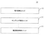
第1態様として、アダプターを提供する。前記アダプターは、第1充電モード及び第2充電モードを有し、前記第1充電モードが定電圧モードであり、前記第2充電モードが定電流モードであり、入力される交流を変換し、出力電圧及び出力電流を取得する電力変換ユニットと、該電力変換ユニットに接続されるサンプリング保持ユニットと、該サンプリング保持ユニットに接続される電流採取制御ユニットとを備え、前記出力電流が第1脈動波形の電流であり、前記サンプリング保持ユニットがサンプリング状態にある場合、前記サンプリング保持ユニットは、前記第1脈動波形の電流をサンプリングするために用いられ、前記サンプリング保持ユニットが保持状態にある場合、前記サンプリング保持ユニットは、前記第1脈動波形の電流のピーク値を保持するために用いられ、前記電流採取制御ユニットは、前記サンプリング保持ユニットが前記保持状態にあるか否かを判断するために用いられ、前記サンプリング保持ユニットが前記保持状態にあると判断された場合に、前記サンプリング保持ユニットにより保持された前記第1脈動波形の電流のピーク値を採取する。 As a first aspect, an adapter is provided. The adapter has a first charging mode and a second charging mode, the first charging mode is a constant voltage mode, the second charging mode is a constant current mode, converts an alternating current input, and outputs A power conversion unit for acquiring a voltage and an output current, a sampling holding unit connected to the power conversion unit, and a current sampling control unit connected to the sampling holding unit, wherein the output current has a first pulsation waveform When the sampling and holding unit is in the sampling state, the sampling and holding unit is used for sampling the current of the first pulsation waveform, and when the sampling and holding unit is in the holding state, the sampling and holding unit is used. The unit is used to hold the peak value of the current of the first pulsation waveform. The current sampling control unit is used to determine whether or not the sampling holding unit is in the holding state. When the sampling holding unit is determined to be in the holding state, the current sampling control unit holds the sampling holding unit. The peak value of the current of the first pulsation waveform is collected.
第2態様として、充電制御方法を提供する。前記方法は、アダプターに適用し、前記アダプターは、第1充電モード及び第2充電モードを有し、前記第1充電モードが定電圧モードであり、前記第2充電モードが定電流モードであり、前記アダプターは、電力変換ユニットと、サンプリング保持ユニットとを備え、前記電力変換ユニットは、入力される交流を変換し、前記出力電圧及び出力電流を取得するために用いられ、前記出力電流が第1脈動波形の電流であり、前記サンプリング保持ユニットが前記電力変換ユニットに接続され、前記サンプリング保持ユニットがサンプリング状態にある場合、前記サンプリング保持ユニットは、前記第1脈動波形の電流をサンプリングするために用いられ、前記サンプリング保持ユニットが保持状態にある場合、前記サンプリング保持ユニットは、前記第1脈動波形の電流のピーク値を保持するために用いられ、前記サンプリング保持ユニットが前記保持状態にあるか否かを判断するステップと、前記サンプリング保持ユニットが前記保持状態にあると判断された場合に、前記サンプリング保持ユニットにより保持された前記第1脈動波形の電流のピーク値を採取するステップとを含む。 As a second aspect, a charge control method is provided. The method is applied to an adapter, and the adapter has a first charging mode and a second charging mode, the first charging mode is a constant voltage mode, and the second charging mode is a constant current mode, The adapter includes a power conversion unit and a sampling holding unit, and the power conversion unit is used to convert input alternating current and obtain the output voltage and output current, and the output current is first. When the sampling holding unit is connected to the power conversion unit and the sampling holding unit is in the sampling state, the sampling holding unit is used to sample the current of the first pulsating waveform. And when the sampling holding unit is in a holding state, the sampling holding unit A step of determining whether the sampling holding unit is in the holding state, and determining that the sampling holding unit is in the holding state, which is used to hold the peak value of the current of the first pulsation waveform And collecting the peak value of the current of the first pulsation waveform held by the sampling holding unit.
本発明の実施形態のアダプターの出力電流は、脈動波形の電流(又は脈動直流電と称する)であり、脈動波形の電流は、電池のリチウム析出現象を低減することができる。また、脈動波形の電流は、充電インターフェースの接点のアーク放電の確率及び強度を減少し、充電インターフェースの寿命を向上することができる。 The output current of the adapter according to the embodiment of the present invention is a pulsating waveform current (or referred to as pulsating direct current), and the pulsating waveform current can reduce the lithium deposition phenomenon of the battery. Also, the pulsating waveform current can reduce the probability and intensity of arcing at the charging interface contacts and improve the life of the charging interface.
本発明の実施形態の明細書をより明確に説明するために、以下、本発明の実施形態において使用する必要のある図面を簡単に説明し、明らかに、以下に説明する図面はただ本発明の一部の実施例であり、当業者にとって、想像の範囲内という前提で、これらの図面に基づいて、他の図面をさらに得ることができる。
以下、本発明の実施形態における添付図面を合わせて、本発明の実施形態における明細書について明確かつ完全な説明を行い、明らかに、説明される実施形態は、本発明の一部の実施例であり、すべての実施例ではない。本発明における実施例に基づいて、当業者の想像の範囲内という前提で得られるすべての他の実施例は、本発明の保護範囲に属すべきである。 DESCRIPTION OF EXEMPLARY EMBODIMENTS The following clearly and completely describes the specification of the embodiments of the present invention with reference to the accompanying drawings in the embodiments of the present invention. The clearly described embodiments are some examples of the present invention. Yes, not all examples. Based on the embodiments of the present invention, all other embodiments obtained on the assumption that they are within the scope of those skilled in the art should fall within the protection scope of the present invention.
関連技術において、充電対象機器(例えば端末)を充電するための第1アダプターが言及された。該第1アダプターが定電圧モードで作動する。定電圧モードにおいて、該第1アダプターの出力電圧は、基本的に、例えば5V、9V、12V又は20Vなどの一定に維持される。 In the related art, a first adapter for charging a device to be charged (for example, a terminal) has been mentioned. The first adapter operates in a constant voltage mode. In the constant voltage mode, the output voltage of the first adapter is basically maintained constant, such as 5V, 9V, 12V or 20V.
第1アダプターの出力電圧は、直接に電池の両端に印加するのに適さず、充電対象機器(例えば端末)内の電池の予期充電電圧及び/又は充電電流が得られるように、先ずは、充電対象機器(例えば端末)内の変換回路を経由して変換する必要がある。 First, the output voltage of the first adapter is not suitable for being directly applied to both ends of the battery. First, charging is performed so that the expected charging voltage and / or charging current of the battery in the charging target device (eg, terminal) can be obtained. It is necessary to perform conversion via a conversion circuit in the target device (for example, a terminal).
変換回路は、第1アダプターの出力電圧に対して変換するために用いられ、電池の予期充電電圧及び/又は充電電流のニーズを満たす。 The conversion circuit is used to convert the output voltage of the first adapter to meet the expected charging voltage and / or charging current of the battery.
一例として、変換回路は、充電管理モジュール、例えば、充電集積回路(integrated circuit,IC)を指す。電池の充電プロセスにおいて、電池の充電電圧及び/又は充電電流に対して管理を行うために用いられる。変換回路は、電圧フィードバックモジュールの機能を有し、及び/又は電流フィードバックモジュールの機能を有することにより、電池の充電電圧及び/又は充電電流に対する管理を実現する。 As an example, the conversion circuit refers to a charge management module, for example, an integrated circuit (IC). It is used to manage the charging voltage and / or charging current of the battery in the battery charging process. The conversion circuit has a function of a voltage feedback module and / or a function of a current feedback module, thereby realizing management of the charging voltage and / or charging current of the battery.
例えば、電池の充電プロセスは、トリクル充電段階、定電流充電段階及び定電圧充電段階のうちの少なくとも一つを含むことができる。トリクル充電段階において、変換回路は、電流フィードバックループを利用して、トリクル充電段階で電池に流れ込む電流が電池の予期充電電流の大きさ(例えば、第1充電電流)を満たすようにすることができる。定電流充電段階において、変換回路は電流フィードバックループを利用して、定電流充電段階で電池に流れ込む電流が電池の予期充電電流の大きさ(例えば、第2充電電流、該第2充電電流は第1充電電流より大きくてもよい)を満たすようにすることができる。定電圧充電段階において、変換回路は電圧フィードバックループを利用して定電圧充電段階で電池の両端に印加する電圧が電池の予期充電電圧の大きさを満たすようにすることができる。 For example, the battery charging process may include at least one of a trickle charging phase, a constant current charging phase, and a constant voltage charging phase. In the trickle charge phase, the conversion circuit may utilize a current feedback loop so that the current flowing into the battery in the trickle charge phase satisfies the expected charge current magnitude (eg, the first charge current) of the battery. . In the constant current charging stage, the conversion circuit uses a current feedback loop so that the current flowing into the battery in the constant current charging stage is the magnitude of the expected charging current of the battery (eg, the second charging current, the second charging current is the first charging current). It may be larger than 1 charging current). In the constant voltage charging stage, the conversion circuit may use a voltage feedback loop so that the voltage applied across the battery in the constant voltage charging stage satisfies the expected charging voltage of the battery.
一例として、第1アダプターの出力電圧が電池の予期充電電圧より大きい場合、降圧変換した後に得られる充電電圧が電池の予期充電電圧のニーズを満たすように、変換回路は、第1アダプターの出力電圧に対して降圧処理を行うために用いられることができる。また一例として、第1アダプターの出力電圧が電池の予期充電電圧より小さい場合、昇圧変換した後に得られる充電電圧が電池の予期充電電圧のニーズを満たすように、変換回路は、第1アダプターの出力電圧に対して昇圧処理を行うために用いられることができる。 For example, when the output voltage of the first adapter is larger than the expected charging voltage of the battery, the conversion circuit may output the output voltage of the first adapter so that the charging voltage obtained after the step-down conversion satisfies the needs of the expected charging voltage of the battery. Can be used to perform a step-down process. As an example, when the output voltage of the first adapter is smaller than the expected charging voltage of the battery, the conversion circuit outputs the output of the first adapter so that the charging voltage obtained after the boost conversion satisfies the needs of the expected charging voltage of the battery. It can be used to boost the voltage.
また一例として、例えば、第1アダプターが5Vの定電圧を出力する。電池は、単一セル(例えばリチウム電池セル、単一セルの充電終止電圧が4.2Vである)を有する場合、降圧した後に得られる充電電圧が電池の予期充電電圧のニーズを満たすように、変換回路(例えばBuck降圧回路)は、第1アダプターの出力電圧に対して降圧処理を行うことができる。 As an example, for example, the first adapter outputs a constant voltage of 5V. If the battery has a single cell (for example, a lithium battery cell, the end-of-charge voltage of the single cell is 4.2V), so that the charge voltage obtained after stepping down meets the battery's expected charge voltage needs, A conversion circuit (for example, a Buck step-down circuit) can perform step-down processing on the output voltage of the first adapter.
また一例として、例えば、第1アダプターが5Vの定電圧を出力する。第1アダプターが複数の単セルを直列接続した電池(例えば、リチウム電池セル、単一セルの充電終止電圧が4.2Vである)を充電する場合、昇圧した後に得られる充電電圧が電池の予期充電電圧のニーズを満たすように、変換回路(例えばBoost昇圧回路)は、第1アダプターの出力電圧に対して昇圧処理を行うことができる。 As an example, for example, the first adapter outputs a constant voltage of 5V. When the first adapter charges a battery in which a plurality of single cells are connected in series (for example, a lithium battery cell, the end-of-charge voltage of a single cell is 4.2 V), the charge voltage obtained after boosting is expected to In order to satisfy the needs of the charging voltage, the conversion circuit (for example, the boost booster circuit) can perform the boosting process on the output voltage of the first adapter.
変換回路が回路の変換効率低下という原因で制限されることは、変換されない分の電気エネルギーが熱量の形でなくなることを招く。この部分の熱量が充電対象機器(例えば端末)の内部に集まる。充電対象機器(例えば端末)の設計スペース及び放熱スペースが非常に小さいため(例えば、ユーザが使用する移動端末の物理的なサイズがますます薄くなるとともに、移動端末の性能を向上させるために、移動端末内に数多くの電子素子を密に配列するようになる)、変換回路の設計難易度を上げ、充電対象機器(例えば端末)内に集まっている熱の迅速除去が難しくなり、さらに、充電対象機器(例えば端末)の異常を引き起こす。 Limitation of the conversion circuit due to a decrease in the conversion efficiency of the circuit causes the electric energy corresponding to the unconverted amount to be lost in the form of heat. The amount of heat in this part collects inside the charging target device (for example, a terminal). The design space and heat dissipation space of the device to be charged (for example, the terminal) is very small (for example, the physical size of the mobile terminal used by the user is becoming increasingly thinner, and the mobile terminal is moved to improve the performance of the mobile terminal. Many electronic elements will be densely arranged in the terminal), the design difficulty of the conversion circuit will be increased, it will be difficult to quickly remove the heat collected in the charging target device (for example, terminal), and the charging target Causes an abnormality of a device (for example, a terminal).
例えば、変換回路に集まっている熱は、変換回路の付近の電子素子に対して熱干渉を引き起こし、電子素子の作動異常の誘因となるおそれがある。また、例えば、変換回路に集まっている熱は、変換回路及び付近の電子素子の使用寿命を短縮するおそれがある。また、例えば、変換回路に集まっている熱は、電池に対して熱干渉を引き起こすおそれがあり、さらに、電池の充放電異常を招く。また、例えば、変換回路に集まっている熱は、充電対象機器(例えば端末)の温度上昇を引き起こすおそれがあり、充電中におけるユーザの使用体験に影響を及ぼす。また、例えば、変換回路に集まっている熱は、変換回路自身の短絡を引き起こすおそれがあり、第1アダプターの出力電圧が直接に電池の両端に印加することにより、充電異常を引き起こし、電池が長時間過電圧充電状態にある場合、電池の爆発さえ引き起こし、ユーザの安全を危険にさらす。 For example, heat collected in the conversion circuit may cause thermal interference with an electronic element in the vicinity of the conversion circuit, and may cause malfunction of the electronic element. Further, for example, heat collected in the conversion circuit may shorten the service life of the conversion circuit and nearby electronic elements. In addition, for example, heat collected in the conversion circuit may cause thermal interference with the battery, and further causes abnormal charging / discharging of the battery. In addition, for example, heat collected in the conversion circuit may cause an increase in the temperature of a device to be charged (for example, a terminal), which affects the user's use experience during charging. In addition, for example, heat collected in the conversion circuit may cause a short circuit of the conversion circuit itself, and when the output voltage of the first adapter is directly applied to both ends of the battery, charging abnormality is caused and the battery is long. When in a time overvoltage charge state, it can even cause an explosion of the battery, jeopardizing user safety.
本発明の一実施形態においては、出力電圧調節可能の第2アダプターを提供する。第2アダプターは、電池の状態情報を取得することができる。電池の状態情報は、電池の現在の電気量情報及び/又は電圧情報を含むことができる。第2アダプターは、取得される電池の状態情報に基づいて第2アダプター自身の出力電圧を調節することにより、電池の予期充電電圧及び/又は充電電流のニーズを満たすができる。さらに、電池充電プロセスの定電流充電段階において、第2アダプターによって調節された後の出力電圧は、直接に電池の両端に印加して電池を充電することができる。 In one embodiment of the present invention, a second adapter with adjustable output voltage is provided. The second adapter can acquire battery state information. The battery status information may include current electricity information and / or voltage information of the battery. The second adapter can meet the needs of the expected charging voltage and / or charging current of the battery by adjusting the output voltage of the second adapter itself based on the acquired battery state information. Furthermore, in the constant current charging stage of the battery charging process, the output voltage after being adjusted by the second adapter can be directly applied to both ends of the battery to charge the battery.
電池の充電電圧及び/又は充電電流に対する管理を実現するために、第2アダプターは、電圧フィードバックモジュールの機能及び電流フィードバックモジュールの機能を有することができる。 In order to realize management of the charging voltage and / or charging current of the battery, the second adapter may have a voltage feedback module function and a current feedback module function.
第2アダプターは、取得される電池の状態情報に基づいて第2アダプター自身の出力電圧を調節する。第2アダプターは、リアルタイムに電池の状態情報を取得し、毎回の取得される電池のリアルタイム状態情報に基づいて第2アダプター自身の出力電圧を調節することができ、電池の予期充電電圧及び/又は充電電流を満たすことを指す。 The second adapter adjusts the output voltage of the second adapter itself based on the acquired battery state information. The second adapter acquires battery state information in real time, and can adjust the output voltage of the second adapter itself based on the battery real-time state information acquired each time. Satisfies charging current.
該第2アダプターは、リアルタイムに取得される電池の状態情報に基づいて第2アダプター自身の出力電圧を調節するとは、充電プロセスにおける電池の電圧が絶えず上昇するにつれて、第2アダプターは、充電プロセスにおける異なる時点の電池の現在の状態情報を取得し、電池の現在の状態情報に基づいて第2アダプター自身の出力電圧をリアルタイムに調節することができ、電池の予期充電電圧及び/又は充電電流のニーズを満たす。 The second adapter adjusts the output voltage of the second adapter itself based on battery state information acquired in real time. As the battery voltage in the charging process constantly increases, the second adapter The current state information of the battery at different points in time can be obtained, and the output voltage of the second adapter itself can be adjusted in real time based on the current state information of the battery, and the expected charging voltage and / or charging current needs of the battery Meet.
例えば、電池の充電プロセスは、トリクル充電段階、定電流充電段階及び定電圧充電段階のうちの少なくとも一つを含むことができる。トリクル充電段階において、第2アダプターは、電流フィードバックループを利用して、トリクル充電段階で第2アダプターから出力されて電池に流れ込む電流が電池の予期充電電流の要求(例えば、第1充電電流)を満たすようにすることができる。定電流充電段階において、第2アダプターは、電流フィードバックループを利用して、定電流充電段階で第2アダプターから出力されて電池に流れ込む電流が電池の予期充電電流の要求(例えば、第2充電電流、第2充電電流は第1充電電流より大きくてもよい)を満たすことができ、また、定電流充電段階において、第2アダプターは、出力される充電電圧を直接に電池の両端に印加して電池を充電することができる。定電圧充電段階において、第2アダプターは電圧フィードバックループを利用して、定電圧充電段階で第2アダプターから出力される電圧が電池の予期充電電圧のニーズを満たす。 For example, the battery charging process may include at least one of a trickle charging phase, a constant current charging phase, and a constant voltage charging phase. In the trickle charge phase, the second adapter uses a current feedback loop to output the battery's expected charge current request (eg, the first charge current) that is output from the second adapter in the trickle charge phase and flows into the battery. Can be met. In the constant current charging stage, the second adapter uses a current feedback loop, and the current output from the second adapter and flowing into the battery in the constant current charging stage is a request for the expected charging current of the battery (for example, the second charging current). The second charging current may be larger than the first charging current), and in the constant current charging stage, the second adapter applies the output charging voltage directly across the battery. The battery can be charged. In the constant voltage charging stage, the second adapter uses a voltage feedback loop, and the voltage output from the second adapter in the constant voltage charging stage meets the needs of the expected charging voltage of the battery.
トリクル充電段階及び定電圧充電段階について、第2アダプターの出力電圧は、第1アダプターに類似する処理方式を採用してもよい。すなわち、充電対象機器(例えば端末)内の変換回路を経由して変換することにより、充電対象機器(例えば端末)内の電池の予期充電電圧及び/又は充電電流が得られる。 For the trickle charging stage and the constant voltage charging stage, the output voltage of the second adapter may adopt a processing method similar to that of the first adapter. That is, the expected charging voltage and / or charging current of the battery in the charging target device (for example, the terminal) can be obtained by performing conversion via the conversion circuit in the charging target device (for example, the terminal).
電池の充電プロセスの信頼性及び安全性を向上させるため、本発明の実施形態は、第2アダプターを制御して脈動波形を有する電圧/電流を出力するようにし、以下、図1に組み合わせて、本発明の一実施形態に係る第2アダプターについて詳しく説明する。 In order to improve the reliability and safety of the battery charging process, the embodiment of the present invention controls the second adapter to output a voltage / current having a pulsation waveform, and is combined with FIG. The second adapter according to one embodiment of the present invention will be described in detail.
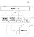
図1は、本発明の一実施形態に係る第2アダプターの構成概略図である。図1の第2アダプター10は、電力変換ユニット11と、サンプリング保持ユニット12と、電流採取制御ユニット13とを備える。 FIG. 1 is a schematic configuration diagram of a second adapter according to an embodiment of the present invention. The
電力変換ユニット11は、第2アダプター10の出力電圧及び出力電流が得られるように、入力される交流を変換するために用いられる。第2アダプター10の出力電流は、第1脈動波形の電流である。 The
サンプリング保持ユニット12が電力変換ユニット11に接続される。サンプリング保持ユニット12がサンプリング状態にある場合、サンプリング保持ユニット12は、第1脈動波形の電流をサンプリングするために用いられる。サンプリング保持ユニット12が保持状態にある場合、サンプリング保持ユニット12は、第1脈動波形の電流のピーク値を保持(又はロックアップ)するために用いられる。 A
電流採取制御ユニット13は、サンプリング保持ユニット12に接続される。電流採取制御ユニット13は、サンプリング保持ユニット12が保持状態にあるか否かを判断し、サンプリング保持ユニット12が保持状態にあると判断された場合に、サンプリング保持ユニット12の保持する第1脈動波形の電流のピーク値を採取するために用いられる。 The current
本発明の実施例の第2アダプターの出力電流は、脈動波形の電流(又は脈動直流電流と称する)であり、脈動波形の電流は、電池のリチウム析出現象を低減することができる。また、脈動波形の電流は、充電インターフェースの接点のアーク放電の確率及び強度を減少し、充電インターフェースの寿命を向上することができる。 The output current of the second adapter of the embodiment of the present invention is a pulsating waveform current (or referred to as a pulsating direct current), and the pulsating waveform current can reduce the lithium deposition phenomenon of the battery. Also, the pulsating waveform current can reduce the probability and intensity of arcing at the charging interface contacts and improve the life of the charging interface.
第2アダプターは、一般的に、実際の状況に合わせて第2アダプターの出力電流を調整する。定電流モードをサポートするする第2アダプターを一例として、第2アダプターは、一般的に、充電対象機器(例えば端末)の電池の電圧に基づいて第2アダプターの出力電流を絶えず調節し、多段階式定電流の方式で電池を充電する。そのため、充電プロセスにおいて、第2アダプターの出力電流をリアルタイムに検出及び制御する必要がある。第2アダプターの出力電流の電流値が一定である場合、第2アダプターの出力電流の検出及び制御が比較的容易に実現される。しかし、本発明の一実施形態において、第2アダプターの出力電流は、第1脈動波形を有する電流であり、第1脈動波形の電流の振幅が変動しているため、第2アダプターの出力電流を検出及び制御する専門的な方式を設計する必要がある。 The second adapter generally adjusts the output current of the second adapter according to the actual situation. Taking the second adapter that supports the constant current mode as an example, the second adapter generally adjusts the output current of the second adapter based on the voltage of the battery of the device to be charged (for example, a terminal) in a multi-step manner. The battery is charged by the constant current method. Therefore, in the charging process, it is necessary to detect and control the output current of the second adapter in real time. When the current value of the output current of the second adapter is constant, the detection and control of the output current of the second adapter can be realized relatively easily. However, in one embodiment of the present invention, the output current of the second adapter is a current having a first pulsation waveform, and the amplitude of the current of the first pulsation waveform varies, so the output current of the second adapter is It is necessary to design a professional method to detect and control.
これに鑑み、本発明の一実施形態は、サンプリング保持ユニット12及び電流採取制御ユニット13を導入し、サンプリング保持ユニット12及び電流採取制御ユニット13により、第2アダプターの出力電流のピーク値を採取することができ、したがって、第2アダプターが出力電流に対する有効な制御を確保することができる。 In view of this, the embodiment of the present invention introduces the
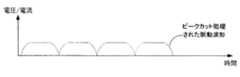
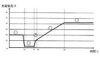
上記に示すように、第2アダプターの出力電流は、第1脈動波形の電流である。本発明における脈動波形は、完全な脈動波形であってもよく、完全な脈動波形をピークカット処理した後に得られる脈動波形であってもよい。上記ピークカット処理とは、脈動波形におけるある閾値を超える部分をフィルタリングすることを指し、脈動波形のピーク値に対する制御を実現する。図2Aに示される実施例において、脈動波形は、完全な脈動波形であり、図2Bに示される実施例において、脈動波形は、ピークカット処理を経た後の脈動波形である。 As described above, the output current of the second adapter is the current of the first pulsation waveform. The pulsation waveform in the present invention may be a complete pulsation waveform, or may be a pulsation waveform obtained after the complete pulsation waveform is subjected to peak cut processing. The peak cut processing refers to filtering a portion exceeding a certain threshold in the pulsation waveform, and realizes control over the peak value of the pulsation waveform. In the embodiment shown in FIG. 2A, the pulsation waveform is a complete pulsation waveform. In the embodiment shown in FIG. 2B, the pulsation waveform is a pulsation waveform after undergoing a peak cut process.
なお、本発明の実施形態は、電力変換ユニット11が交流を第1脈動波形の電流に変換する方式について具体的に限定しない。例えば、電力変換ユニット11における1次フィルタユニット及び2次フィルタユニットを取り去って、第1脈動波形の電流を形成することができる。このようにして、第2アダプター10が第1脈動波形の電流を出力することができるだけでなく、第2アダプター10の体積を大幅に削減することもでき、第2アダプター10の小型化に有利である。 In addition, embodiment of this invention does not specifically limit about the system in which the
本発明の実施形態において、使用される充電対象機器は、「通信端末」(又は「端末」と略す)であることが可能であり、有線回線を経由して接続する(例えば、公衆交換電話網(public switched telephone network,PSTN)、デジタル加入者線(digital subscriber line,DSL)、デジタルケーブル、直接ケーブル接続を経由して接続し、及び/又は別のデータネットワークを経由して接続する)及び/又は(例えば、セルラーネットワーク、無線LAN(wireless local area network,WLAN)、例えば、デジタルビデオブロードキャスティングハンドヘルド(digital video broadcasting handheld,DVB−H)ネットワークのデジタルテレビネットワーク、衛星ネットワーク、振幅変調−周波数変調(amplitude modulation−frequency modulation,AM−FM)ラジオ送信機及び/又は別の通信端末に対する)無線インターフェースを経由して通信信号を受信・送信するように設置される装置を含むが、これらに限定されるわけではない。無線インターフェースを介して通信するように設置される通信端末は、「無線通信端末」、「無線端末」及び/又は「移動端末」と呼ばれてもよい。移動端末の例として、衛星又はセルラー電話と、セルラー無線電話、データ処理、ファックス及びデータ通信機能を組み合わせることのできる個人的通信システム(personal communication system,PCS)端末と、無線電話、ポケベル、インターネット/イントラネットへのアクセス、Webブラウザ、ノートブック、カレンダー及び/又は全地球測位システム(global positioning system,GPS)受信機を含むことができるパーソナルデジタルアシスタント(Personal Digital Assistant,PDA)と、通常のラップトップ型及び/又はパームトップ型受信機又は無線電話トランシーバーを含む他の電子装置とを含むが、これらに限定されるわけではない。 In the embodiment of the present invention, the target device to be used can be a “communication terminal” (or “terminal”), and is connected via a wired line (for example, a public switched telephone network). (Public switched telephone network, PSTN), digital subscriber line (DSL), digital cable, connect via direct cable connection and / or connect via another data network) and / or Or (e.g., cellular network, wireless local area network (WLAN), e.g., digital video broadcasting handheld, DVB-H) network of digital television network, satellite network, amplitude modulation-frequency modulation (AM-FM) radio transmitter and / or via radio interface (to another communication terminal) Including, but not limited to, devices installed to receive and transmit. A communication terminal installed to communicate via a wireless interface may be referred to as a “wireless communication terminal”, “wireless terminal” and / or “mobile terminal”. Examples of mobile terminals include satellite or cellular telephones, cellular wireless telephones, personal communication system (PCS) terminals that can combine data processing, fax and data communication functions, wireless telephones, pagers, Internet / Personal digital assistant (Personal Digital Assistant, PDA) that can include intranet access, web browser, notebook, calendar, and / or global positioning system (GPS) receiver, and regular laptop And / or other electronic devices, including but not limited to palmtop receivers or radiotelephone transceivers. There.
一部の実施例において、第2アダプター10は、充電インターフェース(図19Aの充電インターフェース191を参照)を備えていてもよい。本発明の実施例は、充電インターフェースのタイプについて具体的に限定せず、例えば、ユニバーサル・シリアル・バス(Universal Serial Bus,USB)インターフェースであってもよい。USBインターフェースは、標準USBインターフェースであってもよく、micro USBインターフェースであってもよく、また、Type−Cインターフェースであってもよい。 In some embodiments, the
本発明の実施例は、サンプリング保持ユニット12の実現形態について、具体的に限定せず、一般的には、サンプリング保持ユニット12は、コンデンサにより信号のサンプリング及び保持を実現することができる。以下、図3に組み合わせて、サンプリング保持ユニット12の具体的な形式について詳しく説明する。 The embodiment of the present invention does not specifically limit the implementation form of the sampling and holding
好ましくは、一部の実施例において、図3に示すように、サンプリング保持ユニット12は、電流サンプリングユニット14と、電流保持ユニット15とを備えることができる。電流サンプリングユニット14が電力変換ユニット11に接続され、第1脈動波形の電流を検出して、サンプリング電流を取得し、サンプリング電流をサンプリング電圧に変換するために用いられる。サンプリング電圧は、第1脈動波形の電流の大きさを示すために用いられる。電流保持ユニット15が電流サンプリングユニット14及び電流採取制御ユニット13に接続される。電流保持ユニット15は、電流サンプリングユニット14からサンプリング電圧を受信し、サンプリング電圧に基づいて電流保持ユニット15におけるコンデンサ(図3に図示せず)を充電する。電流採取制御ユニット13は、電流採取制御ユニット13におけるコンデンサの両端の電圧を取得することにより、第1脈動波形の電流のピーク値を採取する。 Preferably, in some embodiments, the sampling and holding
第1脈動波形が立ち上がりエッジにある場合、電流保持ユニット15におけるコンデンサの静電容量は、第1脈動波形の電流の電流値が上昇するにつれて上昇し、サンプリング保持ユニット12は、サンプリング状態にある。第1脈動波形がピーク値又は立ち下がりエッジにある場合、電流保持ユニット15におけるコンデンサの両端の電圧は、そのまま変化せず、サンプリング保持ユニット12は、保持状態にある。 When the first pulsation waveform is at the rising edge, the capacitance of the capacitor in the
本発明の実施例は、電流採取制御ユニット13を介して、サンプリング保持ユニット12により保持された第1脈動波形の電流のピーク値を採取する。一部の実施例において、電流採取制御ユニット13は、アナログデジタル変換器(Analog−to−Digital Converter,ADC)を備えることが可能であり、電流採取制御ユニット13は、ADCにより第1脈動波形の電流のピーク値を採取することができる。一部の実施例において、電流制御ユニット13は、制御ユニットをさらに備えていてもよい。制御ユニットは、例えばマイクロコントロールユニット(Microcontroller Unit,MCU)であることができる。制御ユニットは、ADCポートを備える。制御ユニットは、ADCポートを介してサンプリング保持ユニット12におけるコンデンサに接続されることができ、コンデンサの両端の電圧を取得することにより、第1脈動波形の電流のピーク値を採取する。 The embodiment of the present invention collects the peak value of the current of the first pulsation waveform held by the
サンプリング保持ユニット12がサンプリング状態である場合、コンデンサの両端の電圧は、第1脈動波形の電流の電流値が増加するにつれて増加し、充電プロセスに相当する。サンプリング保持ユニット12が保持状態にある場合、コンデンサの両端の電圧は、最大値に達する。コンデンサの両端の電圧と第1脈動波形の電流値の対応関係をあらかじめ確立してもよい。このようにして、電流採取制御ユニット13は、コンデンサの両端の電圧値を取得することにより、第1脈動波形の電流のピーク値を知ることができる。 When the
好ましくは、一部の実施例において、電流採取制御ユニット13は、第1脈動波形の電流のピーク値を採取した後、サンプリング保持ユニット12を制御して保持状態からサンプリング状態に変換させることに用いられる。 Preferably, in some embodiments, the current
具体的には、第1脈動波形の電流のピーク値は、リアルタイムに変化するおそれがあるため、第1脈動波形の電流のピーク値を絶えず検出する必要があり、電流情報のリアルタイム性及び正確性を確保し、さらに、充電の全プロセスが順調に進むことを確保する。これに基づいて、本発明の実施例が提供する電流採取制御ユニット13は、第1脈動波形の電流のピーク値を採取した後、サンプリング保持ユニット12を制御してサンプリング状態に入るようにすることができ、第1脈動波形の電流に対するサンプリングを再度行い、第1脈動波形の電流ピーク値の取得のリアルタイム性及び正確性を確保する。 Specifically, since the current peak value of the first pulsation waveform may change in real time, it is necessary to constantly detect the peak value of the current of the first pulsation waveform. And ensure that the entire charging process goes smoothly. Based on this, the current
さらに、一部の実施例において、電流採取制御ユニット13は、第1脈動波形の各周期内にピーク値の取得を一回完成してもよく、ピーク値を取得した後、直ちにサンプリング保持ユニット12を制御して保持状態からサンプリング状態に切り替えさせる。このようにして、電流採取制御ユニット13によって取得される第1脈動波形の電流のピーク値は、第1脈動波形の周期を単位として、リアルタイムに更新し、第1脈動波形の電流ピーク値の取得のリアルタイム性及び正確性を確保する。 Furthermore, in some embodiments, the current
上記により、第2アダプター10の出力電流、即ち、充電電流が第1脈動波形の電流である。充電電流は、断続的な方式で電池を充電することができ、充電電流の周期は、電力網の周波数に従って変化することができる。一部の実施例において、充電電流の周期が対応する周波数は、電力網の周波数の整数倍又は逆数倍であってもよい。言い換えると、該充電電流は、断続的な方式で電池を充電することができる。一部の実施例において、該充電電流は、電力網と同期する一つ又は一組の脈動から構成されることができる。 As described above, the output current of the
なお、電流採取制御ユニット13がサンプリング保持ユニット12を制御して保持状態から取得状態に切り替えさせる方式は、一部あってもよい。例えば、電流サンプリングユニット13は、サンプリング保持ユニット12におけるコンデンサを制御して放電させ、コンデンサの両端の電荷をクリアし、次のサンプリング周期が到来する場合、サンプリング保持ユニット12におけるコンデンサを再度充電できるようにする。 Note that there may be some methods in which the current
好ましくは、一部の実施例において、図4に示すように、サンプリング保持ユニット12は、サンプリング保持ユニット12におけるコンデンサ(図4に図示せず)により、第1脈動波形の電流のピーク値を保持する。電流採取制御ユニット13は、放電ユニット16と、制御ユニット17とを備えることができる。放電ユニット16は、制御ユニット17及びサンプリング保持ユニット12におけるコンデンサにそれぞれ接続される。放電ユニット16は、制御ユニット17の制御下で、サンプリング保持ユニット12におけるコンデンサの両端の電荷を解放するために用いられ、したがって、サンプリング保持ユニット12を保持状態からサンプリング状態に変換させる。さらに、サンプリング保持ユニット12により保持された第1脈動波形の電流のピーク値の採取は、制御ユニット17により完成することができる。 Preferably, in some embodiments, as shown in FIG. 4, the
放電ユニット16の実現形態は、他にあってもよい。例えば、放電ユニット16は、サンプリング保持ユニット12におけるコンデンサに直列接続されるスイッチと抵抗を備えていてもよい。放電が必要となる場合、制御ユニット17がスイッチを制御してオフにし、コンデンサを抵抗に対して放電させ、したがって、コンデンサの両端の電荷を消耗する。 There may be other implementations of the
本発明の実施例は、サンプリング保持ユニット12が保持状態にあるか否かを電流採取制御ユニット13が判断する方式について、具体的に限定せず、以下、具体的な実施例に組み合わせて詳しく説明する。 The embodiment of the present invention does not specifically limit the method by which the current
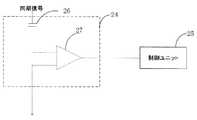
好ましくは、一部の実施例において、電流採取制御ユニット13は、サンプリング保持ユニット12によってサンプリングされた電流値をリアルタイムに検出することができ、二回連続で検出された電流値がそのまま変化しない場合、サンプリング保持ユニット12が保持状態にあることを表明する。 Preferably, in some embodiments, the current
好ましくは、一部の実施例において、電流採取制御ユニット13は、同期信号を受信するために用いられ、同期信号に基づいてサンプリング保持ユニット12が保持状態にあるか否かを判断する。同期信号の周期は、第1脈動波形の周期の1/Nであり、Nは、1以上の整数である。 Preferably, in some embodiments, the current
第1脈動形式の電流が周期的に変化するため、サンプリング保持ユニット12がサンプリング状態から保持状態になる間の時間間隔は、第1脈動波形の電流の周期に関連する(時間間隔は、第1脈動波形の電流の周期の1/2であってもよい)。これに基づいて、本発明の実施例は、第1脈動波形の周期と特定関係を有する同期信号(即ち、同期信号の周期は、第1脈動波形の周期の1/Nである)を導入し、同期信号に基づいてサンプリング保持ユニット12の作動状態を判断する。例えば、同期信号と第1脈動波形の周期及び/又は位相との関係を利用して、第1脈動波形がピーク値又は立ち下がりエッジにあるか否かを決定する。第1脈動波形がピーク値又は立ち下がりエッジにある場合、サンプリング保持ユニット12が保持状態にあると判断する。本文において、第1脈動波形がピーク値又は立ち下がりエッジにあるか否かを決定するとは、第1脈動波形が第1脈動波形のピーク値又は立ち下がりエッジにあるか否かを決定する。代替的には、上記第1脈動波形がピーク値又は立ち下がりエッジにあるか否かを決定するとは、第2アダプターの現在の出力電流が第1脈動波形のピーク値又は立ち下がりエッジにあるか否か、又は第2アダプターの現在の出力電流が第1脈動波形のピーク値又は立ち下がりエッジの対応する電流であるか否かを決定する。 Since the current of the first pulsation type changes periodically, the time interval during which the
好ましくは、一つの実現形態として、第1脈動波形の周期と同期信号の周期が同じである。さらに、一部の実施例において、第1脈動波形と同期信号が位相が同じでありであってもよい。言い換えると、同期信号が立ち上がりエッジにある場合、第1脈動波形は、立ち上がりエッジにあり、同期信号がピーク値又は立ち下がりエッジにある場合、第1脈動波形は、ピーク値又は立ち下がりエッジにある。第1脈動波形がピーク値又は立ち下がりエッジにある場合、サンプリング保持ユニット12が保持状態にあるため、同期信号がいつピーク値又は立ち下がりエッジにあるかを判断すると、サンプリング保持ユニット12がいつ保持状態にあるかを判断することができる。ほかの一部の実施例において、第1脈動波形の位相と同期信号の位相との差が一定であってもよく、例えば差が90度、又は180度である。この場合において、同じく、両者間の周期と位相の関係に基づいて第1脈動波形がいつピーク値又は立ち下がりエッジにあるかを判断することができ、さらに、サンプリング保持ユニット12がいつ保持状態にあるかを判断する。 Preferably, as one embodiment, the period of the first pulsation waveform and the period of the synchronization signal are the same. Further, in some embodiments, the first pulsation waveform and the synchronization signal may have the same phase. In other words, when the synchronization signal is at the rising edge, the first pulsation waveform is at the rising edge, and when the synchronization signal is at the peak value or the falling edge, the first pulsation waveform is at the peak value or the falling edge. . When the first pulsation waveform is at the peak value or the falling edge, the
同期信号の周期が第1脈動波形の周期の1/2、1/3、1/4などである場合、同じく、同期信号と第1脈動波形との位相及び周期の関係に基づいてサンプリング保持ユニット12の作動状態について判断を行う。図5に示すように、同期信号の波形は、実線で示され、第1脈動波形の波形は、破線で示される。同期信号の周期は、第1脈動波形の周期の1/2であり、同期信号がマイナスの半周期にある場合、第1脈動波形は、ピーク値又は立ち下がりエッジにあり、サンプリング保持ユニット12は、保持状態にある。そのため、ただ、同期信号の波形がいつマイナスの半周期にあるかを判断すれば、第1脈動波形がいつピーク値又は立ち下がりエッジにあるかを判断することができる。他の場合は同様であり、ここでは、枚挙しないことにする。 When the period of the synchronization signal is 1/2, 1/3, 1/4, etc. of the period of the first pulsation waveform, the sampling holding unit is similarly based on the phase and period relationship between the synchronization signal and the first pulsation waveform. 12 operation states are determined. As shown in FIG. 5, the waveform of the synchronization signal is indicated by a solid line, and the waveform of the first pulsation waveform is indicated by a broken line. The period of the synchronization signal is ½ of the period of the first pulsation waveform. When the synchronization signal is in the negative half period, the first pulsation waveform is at the peak value or the falling edge, and the
なお、同期信号は、脈動波形の同期信号であってもよく、三角波形の同期信号であってもよく、さらに、他のタイプの同期信号であってもよい。本発明の実施例は、これについて具体的に限定しない。 The synchronization signal may be a pulsating waveform synchronization signal, a triangular waveform synchronization signal, or another type of synchronization signal. Embodiments of the present invention are not specifically limited in this regard.
本発明の実施例は、同期信号の取得方式について具体的に限定せず、以下、具体的な実施例に組み合わせて、同期信号の選択可能な取得方式を提供する。 The embodiment of the present invention does not specifically limit the acquisition method of the synchronization signal, and provides an acquisition method capable of selecting the synchronization signal in combination with a specific embodiment below.
好ましくは、一部の実施例において、電流採取制御ユニット13が電力変換ユニット11に接続され、電力変換ユニット11から同期信号を取得する。 Preferably, in some embodiments, the current
なお、電力変換ユニット11から取得された同期信号は、電力変換ユニット11が受信する交流信号、電力変換ユニット11が1次整流後に取得した電流/電圧信号、電力変換ユニット11の1次から2次に結合された電流/電圧信号、2次整流後の電流/電圧信号などであってもよい。本発明の実施例は、これについて具体的に限定しない。 The synchronization signal acquired from the
好ましくは、一部の実施例において、図6に示すように、電力変換ユニット11は、1次ユニット18と、2次ユニット19とを備えることができる。電流採取制御ユニット13が2次ユニット19に接続され、2次ユニット19から同期信号を取得する。 Preferably, in some embodiments, the
なお、2次ユニット19から同期信号を取得する方式は複数ある。例えば、2次ユニット19のバス(VBUS)から直接に同期信号を取得する。具体的には、第2アダプター10が出力するのが第1脈動波形の電流であり、第2アダプター10の出力端が2次ユニット19のバスに接続されるため、2次ユニット19のバスにも第1脈動波形の電流を有するはずであり、2次ユニット19のバスから直接に同期信号を取得することができる。また、図7に示すように、2次ユニット19は、第1整流ユニット20を備えることができる。第1整流ユニット20が電流採取制御ユニット13に接続される。第1整流ユニット20は、1次ユニット18から2次ユニット19に結合された電流について整流を行い、第2脈動形式の電圧を得て、第2脈動波形の電圧を同期信号として、電流採取制御ユニット13に送信するために用いられる。 There are a plurality of methods for acquiring the synchronization signal from the
2次ユニット19自身は、2次整流ユニットを備える。2次整流ユニットと上記第1整流ユニット20とは、二つの独立した整流ユニットであってもよい。2次整流ユニットは、1次から2次に結合された電流を整流し、第2アダプターの出力電流を得るために用いられる。第1整流ユニットは、1次から2次に結合された電流に対して整流を行い、同期信号を得るために用いられる。図21を参照すると、図21における符号39で示されるユニットは、2次整流ユニットである。2次整流ユニット39及び第1整流ユニット20は、いずれも変圧器T1の2次巻線に近い一側に位置してもよく、したがって、第2アダプターが1次から2次に結合された電流に対して整流を行う。 The
好ましくは、一部の実施例において、図8に示すように、電力変換ユニット11は、1次ユニット18と、2次ユニット19とを備えることができる。電流採取制御ユニット13が1次ユニット18に接続され、1次ユニット18から同期信号を取得する。 Preferably, in some embodiments, the
なお、1次ユニット18から同期信号を取得する方式は複数ある。例えば、1次ユニット18から直接に交流信号を取得し、交流信号を同期信号として電流採取制御ユニット13に送信することができる。また、例えば、1次ユニット18における整流回路によって整流された脈動直流信号を同期信号として、電流採取制御ユニット13に送信することができる。 There are a plurality of methods for acquiring the synchronization signal from the
具体的には、図9に示すように、1次ユニット18が交流ACに対して整流を行い、第3脈動波形の電圧を取得する。第3脈動波形と第1脈動との周期が同じである。1次ユニット18は、光結合ユニット21を介して、第3脈動波形の電圧を第2アダプター10の1次から2次に結合して、第4脈動波形の電圧を取得し、第4脈動波形の電圧を同期信号として、電流採取制御ユニット13に送信することができる。光結合ユニット21は、1次と2次との間の相互干渉を隔離する作用を果たすことができる。代替方式として、1次ユニット18は、光結合ユニット21を経由せずに、第3脈動波形の電圧を電流採取制御ユニット13に直接送信する。本発明の実施例は、これについて具体的に限定しない。 Specifically, as shown in FIG. 9, the
上記具体的な実施例に組み合わせて、電力変換ユニット11から同期信号を取得する方式を詳しく説明したが、同期信号の取得方式は、これに限らず、以下は、同期信号の他の取得方式を提供する。 The method of acquiring the synchronization signal from the
好ましくは、一部の実施例において、電流採取制御ユニット13は、サンプリング保持ユニット12から同期信号を取得することができる。 Preferably, in some embodiments, the current
具体的には、サンプリング保持ユニット12は、第2アダプターの出力電流、即ち第1脈動波形の電流に対してサンプリングを行い、サンプリング電流を取得し、サンプリング保持ユニット12が取得するサンプリング電流、又はサンプリング電流に対応するサンプリング電圧などの信号のいずれも、第1脈動波形の電流と、周期及び位相の両方が同じである。該サンプリング電流又はサンプリング電圧を同期信号にすると、サンプリング保持ユニット12の作動状態についての判断ロジックを簡素化することができる。 Specifically, the
普通の場合に、サンプリング保持ユニット12は、第1脈動波形の電流に対してサンプリングを行い、サンプリング電流を取得し、サンプリング電流をサンプリング電圧に変換する。サンプリング電圧は、第1脈動波形の電流の大きさを示すために用いられることができる。サンプリング保持ユニット12は、該サンプリング電圧を同期信号として、電流採取制御ユニット13に送信することができる。例えば、図21を参照すると、図21の検流計の出力ポート(OUTPUT)から出力される電圧信号を同期信号にすることができる。 In the normal case, the
上記において主に説明したのは同期信号の取得方式であり、以下は、具体的な実施例に組み合わせて、同期信号に基づいて第1脈動波形がピーク値又は立ち下がりエッジにあるか否かを判断する方式を詳しく説明する。 In the above description, the synchronization signal acquisition method is mainly described. The following is combined with a specific embodiment to determine whether the first pulsation waveform is at the peak value or the falling edge based on the synchronization signal. The determination method will be described in detail.
好ましくは、一部の実施例において、電流採取制御ユニット13は、同期信号に基づいて、第1脈動波形がピーク値又は立ち下がりエッジにあるか否かを判断し、第1脈動波形がピーク値又は立ち下がりエッジにあると判断された場合に、サンプリング保持ユニット12により保持された第1脈動波形の電流のピーク値を採取する。 Preferably, in some embodiments, the current
具体的には、サンプリング保持ユニット12は、コンデンサの充放電に基づいて、サンプリング状態と保持状態との間に切り替えを行う。第1脈動波形が立ち上がりエッジにある場合、サンプリング保持ユニット12におけるコンデンサが充電状態にあり、該コンデンサの両端の電圧は、第1脈動波形の電流が増大するにつれて増大し、この場合、サンプリング保持ユニット12がサンプリング状態にある。第1脈動波形がピーク値又は立ち下がりエッジにある場合、該コンデンサの両端の電圧は、引き続き増大せず、この場合、サンプリング保持ユニット12が保持状態にある。そのため、第1脈動波形がいつピーク値又は立ち下がりエッジにあるかを判断することにより、サンプリング保持ユニット12がいつ保持状態にあるかを判断することができる。同期信号の周期及び位相と、第1脈動波形の周期及び位相とが固定の関係を有するため、同期信号の周期及び/又は位相に基づいて、第1脈動波形がピーク値又は立ち下がりエッジにあるか否かを決定することができる。例えば、同期信号と第1脈動波形との位相が同じであり、同期信号がピーク値又は立ち下がりエッジにある場合、第1脈動波形がピーク値又は立ち下がりエッジにある。また、例えば、同期信号と第1脈動波形との周期が同じであり、位相差が半周期であり、同期信号が立ち上がりエッジにある場合、第1脈動波形も、ピーク値又は立ち下がりエッジにある。 Specifically, the
同期信号の位相の検出方式は、様々あってもよい。例えば、電流計又は電圧計により同期信号の電流又は電圧をリアルタイムに検出することができ、したがって、同期信号の位相を決定し、さらに、第1脈動波形がピーク値又は立ち下がりエッジにあるか否かを判断する。しかし、このような実現形態は、追加の電流電圧検出回路が必要であり、実現が複雑である。以下は、2種類のコンパレータに基づく実現形態を提供し、同期信号の電圧と参考電圧とを比較することにより、方便地第1脈動波形がピーク値又は立ち下がりエッジにあるか否かを判断することを便利にする。 There may be various methods for detecting the phase of the synchronization signal. For example, the current or voltage of the synchronization signal can be detected in real time by an ammeter or voltmeter, thus determining the phase of the synchronization signal, and whether the first pulsation waveform is at the peak value or the falling edge. Determine whether. However, such an implementation requires an additional current voltage detection circuit and is complicated to implement. The following provides an implementation based on two types of comparators to determine whether the first pulsation waveform of the flight destination is at a peak value or a falling edge by comparing the voltage of the synchronization signal with a reference voltage Make it convenient.
好ましくは、一部の実施例において、図10に示すように、電流採取制御ユニット13は、コンパレータ22及び制御ユニット23を備えることができる。コンパレータ22の第1入力端は、同期信号を受信するために用いられ、コンパレータ22の第2入力端は、参考電圧を受信するために用いられる。制御ユニット23がコンパレータ22の出力端に接続され、同期信号の電圧と参考電圧との比較結果に基づいて、第1脈動波形がピーク値又は立ち下がりエッジにあるか否かを判断する。一部の実施例において、第1入力端は、コンパレータの同相入力端であり、第2入力端は、コンパレータの逆相入力端である。ほかの一部の実施例において、第1入力端は、コンパレータの逆相入力端であり、第2入力端は、コンパレータの同相入力端である。 Preferably, in some embodiments, the current
なお、本発明の実施例は、参考電圧の電圧値の選択方式について具体的に限定せず、例えば、同期信号がゼロクロス点の脈動波形信号であり、参考電圧の電圧値を0より大きく、同期信号のピーク値より小さいある電圧値とすることができる。例えば、同期信号が交流信号であり、参考電圧の電圧値を0とすることができる。 The embodiment of the present invention does not specifically limit the selection method of the voltage value of the reference voltage. For example, the synchronization signal is a pulsation waveform signal at the zero cross point, the voltage value of the reference voltage is larger than 0, The voltage value may be smaller than the peak value of the signal. For example, the synchronization signal is an AC signal, and the voltage value of the reference voltage can be set to zero.
一方、本発明の実施例は、上記同期信号の電圧と参考電圧との比較結果に基づいて、第1脈動波形がピーク値又は立ち下がりエッジにあるか否かを判断する方式について具体的に限定せず、これは、同期信号の周期及び位相、並びに、第1脈動波形の周期及び位相と関連する。以下、図11及び図12に組み合わせて、例えば、同期信号と第1脈動波形との周期が同じであり、第1脈動波形のピーク値又は立ち下がりエッジの判断方式について例を挙げて説明する。図11及び図12の実施例において、電流採取制御ユニット13は、第1脈動波形の周期毎に、サンプリング保持ユニットにより保持された第1脈動波形の電流のピーク値を採取する。取得完了した後、電流採取制御ユニット13は、放電ユニットにおけるMOS管に制御電圧を直ちに提供し、放電ユニットにおけるMOS管を制御して導通にし、サンプリング保持ユニット12におけるコンデンサの両端の電荷を解放する。ただし、図11及び図12は、例示的な説明に過ぎず、本発明の実施例は、これに限らない。例えば、電流採取制御ユニット13は、複数の周期おきに1次第1脈動波形の電流のピーク値を採取することができる。また、放電ユニットは、MOS管以外の他の実現形態を採用してもよく、例えば他のタイプのスイッチ素子を使用して放電ユニットのオンとオフを実現する。 On the other hand, the embodiment of the present invention specifically limits the method for determining whether the first pulsation waveform is at the peak value or the falling edge based on the comparison result between the voltage of the synchronization signal and the reference voltage. Instead, this is related to the period and phase of the synchronization signal and the period and phase of the first pulsation waveform. Hereinafter, in combination with FIG. 11 and FIG. 12, for example, the method of determining the peak value or the falling edge of the first pulsation waveform with the same period of the synchronization signal and the first pulsation waveform will be described. 11 and 12, the current
図11の実施例において、同期信号と第1脈動波形(第1脈動波形は、ピークカット処理を経た後の脈動波形)との位相が同じである。図11から分かるように、同期信号と第1脈動波形との位相が同じであるため、同期信号がピーク値又は立ち下がりエッジにある場合、第1脈動波形もピーク値又は立ち下がりエッジにある。そのため、同期信号がいつ同期信号の波形のピーク値又は立ち下がりエッジにあるかを判断すれば、第1脈動波形がいつピーク値又は立ち下がりエッジにあるかを知ることができる。 In the embodiment of FIG. 11, the phase of the synchronization signal and the first pulsation waveform (the first pulsation waveform is the pulsation waveform after the peak cut process) are the same. As can be seen from FIG. 11, since the phase of the synchronization signal and the first pulsation waveform are the same, when the synchronization signal is at the peak value or the falling edge, the first pulsation waveform is also at the peak value or the falling edge. Therefore, by determining when the synchronization signal is at the peak value or falling edge of the waveform of the synchronization signal, it is possible to know when the first pulsation waveform is at the peak value or falling edge.
さらに、同期信号がいつピーク値又は立ち下がりエッジにあるかを判断するために、図11の実施例がコンパレータを導入する。コンパレータは、同期信号及び参考電圧の電圧値を比較することにより、コンパレータの出力レベルの変化曲線、即ち図11に示すような矩形波を取得する。矩形波から分かるように、コンパレータの出力レベルが高レベルから低レベルに変換する時点(以下は、目標時点と称する)に、第1脈動波形が立ち下がりエッジにある。この場合、サンプリング保持ユニット12におけるコンデンサは、保持状態にある。そのため、本発明の実施例は、目標時点をピーク値のサンプリング点とし、電流採取制御ユニット13を制御してサンプリング保持ユニット12におけるコンデンサの両端の電圧を取得し、さらに、第1脈動波形の電流のピーク値を採取し、第1脈動波形の電流のピーク値を採取した後、直ちに放電ユニットにおけるMOS管を制御してオンにし、サンプリング保持ユニット12におけるコンデンサの両端の電荷を解放して、次の周期の取得のために準備をする。 Furthermore, the embodiment of FIG. 11 introduces a comparator to determine when the synchronization signal is at a peak value or falling edge. The comparator obtains a change curve of the output level of the comparator, that is, a rectangular wave as shown in FIG. 11, by comparing the voltage value of the synchronization signal and the reference voltage. As can be seen from the rectangular wave, the first pulsation waveform is at the falling edge at the time when the output level of the comparator changes from the high level to the low level (hereinafter referred to as the target time). In this case, the capacitor in the
図12の実施例において、同期信号と第1脈動波形との位相差が180°であり、かつ、第1脈動波形は、ピークカット処理を経た後の脈動波形である。図12から分かるように、同期信号と第1脈動波形との位相差が180°であるため、同期信号がピーク値又は立ち上がりエッジにある場合、第1脈動波形がピーク値又は立ち下がりエッジにある。そのため、同期信号がいつピーク値又は立ち上がりエッジにあるかを判断すれば、第1脈動波形がいつピーク値又は立ち下がりエッジにあるかを知ることができる。 In the embodiment of FIG. 12, the phase difference between the synchronization signal and the first pulsation waveform is 180 °, and the first pulsation waveform is the pulsation waveform after the peak cut processing. As can be seen from FIG. 12, since the phase difference between the synchronization signal and the first pulsation waveform is 180 °, when the synchronization signal is at the peak value or the rising edge, the first pulsation waveform is at the peak value or the falling edge. . Therefore, by determining when the synchronization signal is at the peak value or the rising edge, it is possible to know when the first pulsation waveform is at the peak value or the falling edge.
さらに、同期信号がいつピーク値又は立ち上がりエッジにあるかを判断するために、図12の実施例は、コンパレータを導入する。コンパレータは、同期信号及び参考電圧の電圧値を比較することにより、コンパレータの出力レベルの変化曲線、即ち、図12に示すような矩形波を取得する。矩形波から分かるように、コンパレータの出力レベルが低レベルから高レベルに変換する時点(以下、目標時点と称する)に、第1脈動波形が立ち下がりエッジにある。この場合、サンプリング保持ユニット12におけるコンデンサが保持状態にある。そのため、本発明の実施例は、目標時点をピーク値のサンプリング点とし、サンプリング保持ユニット12におけるコンデンサの両端の電圧を取得するように電流採取制御ユニット13を制御し、さらに、第1脈動波形の電流のピーク値を採取し、第1脈動波形の電流のピーク値を採取した後、直ちに放電ユニットにおけるMOS管を制御してオンにし、サンプリング保持ユニット12におけるコンデンサの両端の電荷を解放して、次の周期の取得のために準備をする。 Further, in order to determine when the synchronization signal is at the peak value or rising edge, the embodiment of FIG. 12 introduces a comparator. The comparator obtains a change curve of the output level of the comparator, that is, a rectangular wave as shown in FIG. 12, by comparing the voltage value of the synchronization signal and the reference voltage. As can be seen from the rectangular wave, the first pulsation waveform is at the falling edge at the time when the output level of the comparator is converted from the low level to the high level (hereinafter referred to as the target time). In this case, the capacitor in the
好ましくは、ほかの一部の実施例において、図13に示すように、電流採取制御ユニット13は、比較ユニット24と、制御ユニット25とを備える。比較ユニット24は、コンデンサ26及びコンパレータ27を備えることができる。コンデンサ26は、同期信号を受信するために用いられ、同期信号における直流信号をフィルタリングして、ゼロクロス点の交流信号を取得する。コンパレータ27の第1入力端がコンデンサ26に接続され、交流信号を受信するために用いられる。コンパレータ27の第2入力端は、参考電圧を受信するために用いられる。コンパレータ27は、交流信号の電圧と参考電圧とを比較するために用いられる。制御ユニット25がコンパレータ27の出力端に接続され、交流信号の電圧と参考電圧の比較結果に基づいて、第1脈動波形がピーク値又は立ち下がりエッジにあるか否かを判断する。さらに、本発明の実施例において、参考電圧の電圧値は、0と設置することができる。一部の実施例において、第1入力端は、コンパレータの同相入力端であり、第2入力端は、コンパレータの逆相入力端である。ほかの一部の実施例において、第1入力端は、コンパレータの逆相入力端であり、第2入力端は、コンパレータの同相入力端である。 Preferably, in some other embodiments, the current
同期信号が、脈動波形信号であることを一例として、脈動波形の信号は、直流信号(又は直流成分)とゼロクロス点の交流信号(又は交流成分)とを混合することにより構成された信号と見なすことができる。コンデンサ26により、脈動波形信号における直流信号をフィルタリングすることができ、ゼロクロス点の交流信号を残る。このような実現形態において、コンパレータ27の参考電圧を0と設置すれば(例えば、コンパレータの第2入力端を接地させる)、同期信号の位相を判断することを便利にすることができる。 Taking the synchronization signal as a pulsating waveform signal as an example, the pulsating waveform signal is regarded as a signal configured by mixing a DC signal (or DC component) and an AC signal (or AC component) at the zero crossing point. be able to.
さらに、本発明の実施例において、交流信号及び参考電圧に基づいて、同期信号、第1脈動波形がピーク値又は立ち下がりエッジにあるか否かを判断する方式は様々あり、これは、交流信号の周期及び位相、並びに、第1脈動波形の周期及び位相と関連し、具体的な判断方式は、図11及び図12で説明する判断方式に類似し、ここでは、詳しく説明しない。 Furthermore, in the embodiment of the present invention, there are various methods for determining whether the synchronization signal and the first pulsation waveform are at the peak value or the falling edge based on the AC signal and the reference voltage. The specific determination method is similar to the determination method described with reference to FIGS. 11 and 12 and will not be described in detail here.
上記では、第1脈動波形の電流ピーク値の取得方式を詳しく説明した。以下では、具体的な実施例に組み合わせて、取得される第1脈動波形の電流ピーク値に基づく充電プロセスの制御方式について詳しく説明する。 In the above, the acquisition method of the current peak value of the first pulsation waveform has been described in detail. Hereinafter, a control method of the charging process based on the acquired current peak value of the first pulsation waveform will be described in detail in combination with a specific embodiment.
好ましくは、一部の実施例において、図14に示すように、第2アダプター10は、電圧調整ユニット28をさらに備えることができる。電圧調整ユニット28が電力変換ユニット11に接続され、第2アダプター10の出力電圧を検出して調整するために用いられる。電流採取制御ユニット13は、電圧調整ユニット28に接続され、電圧調整ユニット28を介して、第1脈動波形の電流のピーク値を調整する。 Preferably, in some embodiments, as shown in FIG. 14, the
なお、電圧調整ユニット28の最も基本の機能は、第2アダプターの出力電圧の調整を実現することである。具体的には、電圧調整ユニット28は、電力変換ユニット11を介して第2アダプター10の出力電圧を検出し、電力変換ユニット11を介して第2アダプター10の出力電圧に対して調整を行う。言い換えると、電圧調整ユニット28と電力変換ユニット11とが第2アダプターの出力電圧のフィードバック制御システムを形成し、該フィードバック制御システムを電圧フィードバックループと称してもよい。なお、第2アダプターの出力電力が一定である場合に、電圧に対する調整も、電流の変化を引き起こす。そのため、本発明の実施例の電流採取制御ユニット13が第1脈動波形の電流のピーク値を採取した後、上記電圧フィードバックループを利用して電流の調整を実現することができる。例えば、電流採取制御ユニット13が第1脈動波形の電流の現在のピーク値を取得した後、該現在のピーク値を目標ピーク値に調整しようとする場合、ソフトウェアにより、第1脈動波形の電流のピーク値を目標ピーク値に調整する際に、対応する第2アダプター10の出力電圧の目標値を算出し、その後、上記電圧フィードバックループを利用して第2アダプター10の出力電圧を目標値に調整すればよい。 The most basic function of the
本発明の実施例の電流採取制御ユニット13と電圧フィードバックループとが第2アダプターの出力電流のピーク値のフィードバック制御システムを形成した。フィードバック制御システムは、電流フィードバックループと称してもよい。つまり、本発明の実施例は、電圧フィードバックループ(ハードウェアにより実現する)を含むだけでなく、電流フィードバックループ(電圧フィードバックループに基づき、ソフトウェアにより算出して実現する)をも含み、よって、第2アダプターは、第2アダプターの出力電圧の制御を実現することができるほか、第2アダプターの出力電流の制御を実現することもでき、第2アダプターの機能を豊富にし、第2アダプターの智能度合を向上する。 The current
電流採取制御ユニット13が電圧調整ユニット28を介して第1脈動波形の電流のピーク値を調整する方式は、様々あってもよい。以下、図15及び図17に組み合わせて一例を挙げて説明する。 There may be various ways in which the current
好ましくは、一部の実施例において、図15に示すように、電圧調整ユニット28は、電圧サンプリングユニット29と、電圧比較ユニット30と、電圧制御ユニット31とを含むことができる。電圧サンプリングユニット29が電力変換ユニット11に接続され、電圧比較ユニット30の入力端が電圧サンプリングユニット29に接続され、第1電圧と第1参考電圧を比較するために用いられる。電圧制御ユニット31の入力端が電圧比較ユニット30の出力端に接続される。電圧制御ユニット31の出力端が電力変換ユニット11に接続される。電圧制御ユニット31は、第1電圧と第1参考電圧との比較結果に応じて、第2アダプター10の出力電圧を制御する。電流採取制御ユニット13が電圧比較ユニット30に接続され、第1参考電圧の電圧値を調整することにより、第1脈動波形の電流のピーク値を調整する。 Preferably, in some embodiments, as shown in FIG. 15, the
具体的には、第2アダプターの出力電圧を採取するために、電圧サンプリングユニット29の入力端が第2アダプターのバス(VBUS)に接続されてもよい。一部の実施例において、電圧サンプリングユニット29は、導線であってもよい。このようにして、電圧サンプリングユニット29によってサンプリングされる第1電圧は、即ち、第2アダプターの出力電圧である。ほかの一部の実施例において、電圧サンプリングユニット29は、分圧のための二つの抵抗を備えていてもよい。このようにして、電圧サンプリングユニット29によってサンプリングされる第1電圧は、二つの抵抗で分圧された後に得られる電圧である。電圧比較ユニット30は、演算増幅器により実現することができる。演算増幅器の一つの入力端は、電圧サンプリングユニット29によって入力される第1電圧を受信するために用いられ、もう一つの入力端は、第1参考電圧を受信するために用いられる。演算増幅器の出力端は、電圧フィードバック信号を生成し、第1電圧と第1参考電圧は、等しいであるか否かを示す。電圧制御ユニット31は、光結合とPWMコントローラなどの素子により実現し、電圧比較ユニット30によって提供される電圧フィードバック信号に基づいて、第2アダプターの出力電圧に対して調整を行う。第2アダプターの出力電力が一定である場合に、電流採取制御ユニット13は、第1脈動波形の電流のピーク値の所期値に基づいて、対応する第2アダプターの出力電圧の所期値を算出する。その後、第1参考電圧の電圧値を調節することにより、第2アダプターの出力電圧を該第2アダプターの出力電圧の所期値に調整し、したがって、第1脈動波形の電流のピーク値を第1脈動波形の電流のピーク値の所期値に調整する。 Specifically, in order to collect the output voltage of the second adapter, the input end of the
電流採取制御ユニット13が第1参考電圧の電圧値を調整する方式は一部あってもよい。好ましくは、一つの実施例として、図16に示すように、電流採取制御ユニット13は、制御ユニット32と、デジタルアナログ変換器(Digital to Analog Converter,DAC)33と、を備えていてもよい。DAC33の入力端が制御ユニット32に接続され、DAC33の出力端が電圧比較ユニット30に接続される。制御ユニット32は、DAC33を介して第1参考電圧の電圧値を調整することにより、第1脈動波形の電流のピーク値を調整する。好ましくは、もう一つの実施例として、制御ユニット32は、RCユニット、ディジタルポテンショメータなどの回路を介して第1参考電圧の電圧値の調節を実現することができ、本発明の実施例は、これについて具体的に限定しない。 There may be some methods in which the current
好ましくは、一部の実施例において、図17に示すように、電圧調整ユニット28は、分圧ユニット34と、電圧比較ユニット30と、電圧制御ユニット31とを備えることができる。分圧ユニット34の入力端が電力変換ユニット11に接続され、設定される分圧比に基づいて第2アダプター10の出力電圧に対して分圧を行い、第2電圧を生成するために用いられる。電圧比較ユニット30の入力端が分圧ユニット34の出力端に接続され、第2電圧と第2参考電圧とを比較するために用いられる。電圧制御ユニット31の入力端が電圧比較ユニット30の入力端に接続される。電圧制御ユニット31の出力端が電力変換ユニット11に接続される。電圧制御ユニット31は、第2電圧と第2参考電圧との比較結果に応じて、第2アダプター10の出力電圧を制御する。電流採取制御ユニット13が電圧比較ユニット30に接続され、分圧比を調整することにより、第1脈動波形の電流のピーク値を調整する。 Preferably, in some embodiments, as shown in FIG. 17, the
本発明の実施例は図15の実施例に類似し、異なる点としては、本発明の実施例が分圧ユニットを導入する点にある。分圧ユニットの分圧比は、調節可能である。さらに、本発明の実施例における電流採取制御ユニット13は、電圧比較ユニット30の参考電圧を調整することにより、第1脈動波形の電流のピーク値に対して調整を行うことではなく、分圧ユニット34の分圧比を調整することにより、第1脈動波形の電流のピーク値に対して調整を行う。本発明の実施例は、分圧ユニットに基づいて、第2アダプターの出力電圧のサンプリングを実現するほか、第1脈動波形の電流のピーク値の調節をも実現し、第2アダプターの回路構成を簡素化する。 The embodiment of the present invention is similar to the embodiment of FIG. 15 with the difference that the embodiment of the present invention introduces a voltage dividing unit. The partial pressure ratio of the partial pressure unit is adjustable. Furthermore, the current
なお、本発明の実施例は、分圧ユニットの分圧比を調節することにより、第1脈動波形の電流のピーク値の調節を実現するため、本発明の実施例における電圧比較ユニットの参考電圧(即ち上記の第2参考電圧)は、一定であってもよい。 The embodiment of the present invention realizes the adjustment of the peak value of the current of the first pulsation waveform by adjusting the voltage dividing ratio of the voltage dividing unit, so that the reference voltage of the voltage comparison unit in the embodiment of the present invention ( That is, the second reference voltage) may be constant.
本発明の実施例の分圧ユニット34の実現形態は様々ある。例えば、ディジタルポテンショメータを採用して実現してもよく、分散された抵抗、スイッチなどの素子により上記分圧及び分圧比調節の機能を実現してもよい。 There are various implementations of the
ディジタルポテンショメータの実現形態を一例として、図18に示すように、電流採取制御ユニット13は、制御ユニット32を備える。分圧ユニット34は、ディジタルポテンショメータ35を備える。ディジタルポテンショメータ35の高電位端が電力変換ユニット11に接続される。ディジタルポテンショメータ35の低電位端が接地される。ディジタルポテンショメータ35の出力端が電圧比較ユニット30に接続される。制御ユニット32は、ディジタルポテンショメータ35の制御端に接続され、ディジタルポテンショメータ35の制御端を介してディジタルポテンショメータ35の分圧比を調整することにより、第1脈動波形の電流のピーク値を調整する。 Taking a digital potentiometer as an example, the current
好ましくは、一部の実施例において、第2アダプター10は、第1充電モード及び第2充電モードを有することができる。第2アダプター10の第2充電モード下の充電対象機器(例えば端末)に対する充電速度が第2アダプター10の第1充電モード下の充電対象機器(例えば端末)に対する充電速度(上記第1脈動波形の電流が第2アダプターの前記第2充電モード下の出力電流であってもよい)より速い。言い換えると、同じ容量の充電対象機器(例えば端末)における電池を充満するのに費やした時間については、第1充電モードで作動する第2アダプター10に対し、第2充電モードで作動する第2アダプター10のほうがより短い。 Preferably, in some embodiments, the
第2アダプター10は、制御ユニットを備える。第2アダプター10が充電対象機器(例えば端末)と接続するプロセスにおいて、制御ユニットが充電対象機器(例えば端末)と双方向通信を行い、第2充電モードの充電プロセスを制御する。制御ユニットは、上記いずれの実施例における制御ユニットであってもよく、例えば、第1調整ユニットにおける制御ユニットであってもよく、第2調整ユニットにおける制御ユニットであってもよい。 The
第1充電モードは、普通充電モードであることが可能であり、第2充電モードは、急速充電モードであることができる。普通充電モードとは、第2アダプターが比較的小さい電流値(通常は、2.5Aより小さい)を出力して、又は比較的小さい電力(通常は、15Wより小さい)で、充電対象機器(例えば端末)における電池を充電する。普通充電モードにおいて、比較的大容量の電池(例えば3000アンペア時間容量の電池)を完全に充満しようとするなら、通常は、数時間をかける必要があり、急速充電モードにおいて、第2アダプターは、比較的大きい電流(通常は、2.5Aより大きく、例えば4.5A、5A、さらにこれより高い)を出力し、又は比較的大きい電力(通常より大きいと等しい15W)で充電対象機器(例えば端末)における電池を充電し、普通充電モードに対し、第2アダプターが急速充電モードにおいて、同じ容量の電池を完全に充満するのに必要とする充電時間を明らかに短縮することができ、充電速度がより速い。 The first charging mode can be a normal charging mode, and the second charging mode can be a quick charging mode. In the normal charging mode, the second adapter outputs a relatively small current value (usually less than 2.5 A) or with relatively small power (usually less than 15 W), and the charging target device (for example, Charge the battery in the terminal. In normal charging mode, if you want to fully charge a relatively large capacity battery (for example, a battery with a capacity of 3000 amps), you usually need to spend several hours. In fast charging mode, the second adapter Output a relatively large current (usually greater than 2.5A, for example 4.5A, 5A or even higher), or a device to be charged (for example, a terminal) with relatively large power (15W equal to greater than normal) ), The charging time required for the second adapter to fully charge a battery of the same capacity in the quick charging mode can be obviously reduced compared to the normal charging mode, and the charging speed is Faster.
本発明の実施例は、第2アダプターの制御ユニットと充電対象機器(例えば端末)との通信内容、及び制御ユニットが第2アダプターの第2充電モード下の出力に対する制御方式について具体的に限定しない。例えば、制御ユニットは、充電対象機器(例えば端末)と通信して、充電対象機器(例えば端末)における電池の現在電圧又は現在電気量を交互に通信し、電池の現在電圧又は現在電気量に基づいて、第2アダプターの出力電圧又は出力電流を調整することができる。以下、具体的な実施例に組み合わせて、制御ユニットと充電対象機器(例えば端末)との間の通信内容、及び制御ユニットが第2充電モード下の第2アダプターの出力に対する制御方式について詳しく説明する。 The embodiment of the present invention does not specifically limit the communication contents between the control unit of the second adapter and the device to be charged (for example, the terminal) and the control method for the output of the second adapter in the second charging mode of the second adapter. . For example, the control unit communicates with a charging target device (for example, a terminal), and alternately communicates the current voltage or current amount of the battery in the charging target device (for example, terminal), based on the current voltage or current amount of the battery. Thus, the output voltage or output current of the second adapter can be adjusted. Hereinafter, in combination with a specific embodiment, details of communication between the control unit and the charging target device (for example, a terminal) and a control method for the output of the second adapter under the second charging mode by the control unit will be described in detail. .
好ましくは、一部の実施例において、制御ユニットが充電対象機器(例えば端末)と双方向通信を行い、第2充電モード下の第2アダプターの出力を制御するプロセスは、制御ユニットが充電対象機器(例えば端末)と双方向通信を行い、第2アダプターと充電対象機器(例えば端末)との間の充電モードをネゴシエーションするステップを含むことができる。 Preferably, in some embodiments, the process in which the control unit performs two-way communication with a charging target device (for example, a terminal) and controls the output of the second adapter under the second charging mode is performed by the control unit. It may include a step of performing bidirectional communication with (for example, a terminal) and negotiating a charging mode between the second adapter and a charging target device (for example, a terminal).
本発明の実施例において、第2アダプターは、第2充電モードを盲目的に採用して充電対象機器(例えば端末)に対して急速充電を行うことではなく、充電対象機器(例えば端末)と双方向通信を行い、第2アダプターは、第2充電モードを採用して充電対象機器(例えば端末)に対して急速充電を行うことができるかどうかについてネゴシエーションし、このようにして、充電プロセスの安全性を向上させることができる。 In the embodiment of the present invention, the second adapter blindly adopts the second charging mode and does not charge the charging target device (for example, the terminal) quickly, but both the charging target device (for example, the terminal). The second adapter adopts the second charging mode to negotiate whether or not the charging target device (for example, the terminal) can be rapidly charged, and thus makes the charging process safe. Can be improved.
具体的には、制御ユニットが充電対象機器(例えば端末)と双方向通信を行い、第2アダプターと充電対象機器(例えば端末)との間の充電モードをネゴシエーションするステップは、制御ユニットが充電対象機器(例えば端末)に充電対象機器(例えば端末)が第2充電モードをオンにするか否かを問い合わせるための第1命令を送信するステップと、制御ユニットが第1命令に対する充電対象機器(例えば端末)から送信される充電対象機器(例えば端末)が第2充電モードをオンにすることに同意するかどうかを示すための返信命令を受信するステップと、充電対象機器(例えば端末)が第2充電モードをオンにすることに同意された場合に、制御ユニットが第2充電モードを使用して充電対象機器(例えば端末)を充電するステップとを含むことができる。 Specifically, the control unit performs two-way communication with a charging target device (for example, a terminal) and negotiates a charging mode between the second adapter and the charging target device (for example, a terminal). Transmitting a first command for inquiring whether or not the charging target device (for example, the terminal) turns on the second charging mode to the device (for example, the terminal), and the control unit for the charging target device (for example, the first command) A charging target device (for example, the terminal) transmitted from the terminal) receives a reply command for indicating whether or not to agree to turn on the second charging mode; and the charging target device (for example, the terminal) When the control unit agrees to turn on the charging mode, the control unit uses the second charging mode to charge the charging target device (for example, the terminal). It can contain.
本発明の実施例の上記説明は、第2アダプター(又は第2アダプターの制御ユニット)と充電対象機器(例えば端末)との主従性について限定することではなく、言い換えると、制御ユニットと充電対象機器(例えば端末)のうちのいずれも主装置側として、双方向通信セッションを発起することができ、したがって、相手方が従装置側として主装置側が発起する通信に対して第1応答又は第1返信を出す。可能な方式として、通信プロセスにおいて、第2アダプター側及び充電対象機器(例えば端末)側の大地に対するレベルの高さを比較することにより、主装置及び従装置のアイデンティティを確認することができる。 The above description of the embodiment of the present invention is not limited to the master slave of the second adapter (or the control unit of the second adapter) and the charging target device (for example, terminal), in other words, the control unit and the charging target device. Any of the (for example, terminals) can initiate a two-way communication session on the master device side, so that the other party sends a first response or a first reply to communication initiated by the master device side as a slave device side. put out. As a possible method, in the communication process, the identity of the master device and the slave device can be confirmed by comparing the height of the level with respect to the ground on the second adapter side and the charging target device (for example, terminal) side.
本発明の実施例は、第2アダプター(又は第2アダプターの制御ユニット)と充電対象機器(例えば端末)との間の双方向通信の具体的な実現形態について制限を施すことではなく、つまり、第2アダプター(又は第2アダプターの制御ユニット)と充電対象機器(例えば端末)とのうちのいずれも主装置側として通信セッションを発起することができ、したがって相手方が従装置側として、主装置側が発起する通信セッションに対して第1応答又は第1返信を出し、同時に、主装置側は、従装置側の第1応答又は第1返信に対して第2応答を出すことができ、即ち、主装置及び従装置の間に充電モードのネゴシエーションプロセスが一回完成される。可能な実施方式として、主装置及び従装置の間に充電モードのネゴシエーションが何度も完成された後、主装置及び従装置の間の充電操作を実行することができ、ネゴシエーション後の充電プロセスが安全かつ確実に実行されることを確保する。 The embodiment of the present invention does not limit the specific implementation of bidirectional communication between the second adapter (or the control unit of the second adapter) and the charging target device (for example, a terminal), that is, Any of the second adapter (or the control unit of the second adapter) and the charging target device (for example, a terminal) can initiate a communication session as the master device side, so that the other party is the slave device side and the master device side is the master device side. A primary response or a first reply can be sent to the originating communication session, and at the same time, the master device can send a second response to the slave device's first response or the first reply. The charge mode negotiation process is completed once between the device and the slave device. As a possible implementation, after the charging mode negotiation between the master device and the slave device is completed many times, the charging operation between the master device and the slave device can be executed, and the charging process after the negotiation is Ensure that it is executed safely and reliably.
主装置側として、従装置側の通信セッションに対する第1応答又は第1返信に応じて第2応答を出す一つの方式は、さらに、主装置側が従装置側の通信セッションに対する第1応答又は第1返信を受信し、受信された従装置の第1応答又は第1返信に応じて目標性のある第2応答を出すことができる。一例として、主装置側が所定時間内に従装置側の通信セッションに対する第1応答又は第1返信を受信する場合、主装置側は、従装置の第1応答又は第1返信に対して目標性のある第2応答を出す。具体的には、主装置側と従装置側とが充電モードのネゴシエーションを一回完成し、主装置側と従装置側との間がネゴシエーション結果に応じて、第1充電モード又は第2充電モードに基づいて充電操作を実行し、即ち、第2アダプターがネゴシエーション結果に応じて、第1充電モード又は第2充電モードで作動して充電対象機器(例えば端末)を充電する。 One method in which the main device issues a second response in response to the first response or the first reply to the communication session on the slave device side is further the first response or first response from the master device side to the communication session on the slave device side. A reply can be received, and a second response with a target can be issued in response to the received first response or first reply of the slave device. As an example, when the master device receives the first response or the first reply for the communication session of the slave device within a predetermined time, the master device has a target property for the first response or the first reply of the slave device. Issue a second response. Specifically, the main device side and the slave device side complete the negotiation of the charging mode once, and the main device side and the slave device side are in the first charge mode or the second charge mode depending on the negotiation result. In other words, the second adapter operates in the first charging mode or the second charging mode according to the negotiation result to charge the device to be charged (for example, the terminal).
主装置側として、従装置側の通信セッションに対する第1応答又は第1返信に応じて更なる第2応答を出すことのできる一つの方式は、主装置側が所定時間内に従装置側の通信セッションに対する第1応答又は第1返信を受信せずとも、主装置側が従装置の第1応答又は第1返信に対して目標性のある第2応答を出す。例として、主装置側が所定時間内に従装置側の通信セッションに対する第1応答又は第1返信を受信せずとも、主装置側が従装置の第1応答又は第1返信に対して目標性のある第2応答を出すとは、具体的には、主装置側と従装置側とが充電モードのネゴシエーションを一回完成し、主装置側と従装置側との間に第1充電モードに基づいて充電操作が実行され、即ち、第2アダプターが第1充電モードで作動して充電対象機器(例えば端末)を充電する。 One method by which the main device side can send a further second response in response to the first response or the first reply to the communication session on the slave device side is that the master device side has a communication session on the slave device side within a predetermined time. Even if the first response or the first reply is not received, the main device issues a second response with a target to the first response or the first reply of the slave device. As an example, even if the master device does not receive the first response or the first reply for the communication session of the slave device within a predetermined time, the master device has the target for the first response or the first reply of the slave device Specifically, when the second response is issued, the master device side and the slave device side complete the charge mode negotiation once, and the master device side and the slave device side are based on the first charge mode. A charging operation is performed, that is, the second adapter operates in the first charging mode to charge a device to be charged (for example, a terminal).
好ましくは、一部の実施例において、充電対象機器(例えば端末)が主装置として、通信セッションを発起する場合、第2アダプター(又は第2アダプターの制御ユニット)が従装置として、主装置側が発起する通信セッションに対して第1応答又は第1返信を出した後、充電対象機器(例えば端末)が第2アダプターの第1応答又は第1返信に対して目標性のある第2応答を出さなくとも、第2アダプター(又は第2アダプターの制御ユニット)と充電対象機器(例えば端末)との間に充電モードのネゴシエーションプロセスが一回完成されると認め、さらに、第2アダプターがネゴシエーション結果に応じて第1充電モード又は第2充電モードで充電対象機器(例えば端末)を充電することを決定することができる。 Preferably, in some embodiments, when a charging target device (for example, a terminal) starts a communication session as a main device, the second adapter (or a control unit of the second adapter) starts as a slave device, and the main device starts After issuing the first response or the first reply to the communication session to be performed, the charging target device (for example, the terminal) does not send the second response with the target property to the first response or the first reply of the second adapter. In both cases, it is recognized that the negotiation process of the charging mode is completed once between the second adapter (or the control unit of the second adapter) and the charging target device (for example, the terminal), and the second adapter responds to the negotiation result. Then, it can be determined to charge the device to be charged (for example, the terminal) in the first charging mode or the second charging mode.
好ましくは、一部の実施例において、制御ユニットが充電対象機器(例えば端末)と双方向通信を行い、第2アダプターの第2充電モード下の出力のプロセスを制御するステップは、制御ユニットが充電対象機器(例えば端末)と双方向通信を行い、第2充電モード下の第2アダプターが出力する充電対象機器(例えば端末)を充電するための充電電圧を決定するステップと、制御ユニットが第2アダプターの出力電圧に対して調整を行い、第2アダプターの出力電圧と、第2充電モード下の第2アダプターが出力する充電対象機器(例えば端末)を充電するための充電電圧とを等しくするステップとを含むことができる。 Preferably, in some embodiments, the control unit performs two-way communication with a charging target device (for example, a terminal), and the step of controlling the output process of the second adapter under the second charging mode is performed by the control unit. Determining a charging voltage for charging a charging target device (for example, a terminal) output from the second adapter under the second charging mode by performing bidirectional communication with the target device (for example, a terminal); A step of adjusting the output voltage of the adapter so that the output voltage of the second adapter is equal to the charging voltage for charging the charging target device (for example, terminal) output by the second adapter under the second charging mode. Can be included.
具体的には、制御ユニットが充電対象機器(例えば端末)と双方向通信を行い、第2充電モード下の第2アダプターが出力する充電対象機器(例えば端末)を充電するための充電電圧を決定するステップは、制御ユニットが充電対象機器(例えば端末)に第2アダプターの出力電圧と充電対象機器(例えば端末)の電池の現在電圧とがマッチングするかどうかを問い合わせるための第2命令を送信するステップと、制御ユニットが充電対象機器(例えば端末)から送信される第2アダプターの出力電圧が電池の現在電圧とマッチングし、やや高い又はやや低いことを示すための第2命令の返信命令を受信するステップを含むことができる。代替的には、第2命令は、第2アダプターの現在の出力電圧を第2充電モード下の第2アダプターが出力する充電対象機器(例えば端末)を充電するための充電電圧とするのは適合であるかどうかを問い合わせるために用いられ、第2命令の返信命令は、現在第2アダプターの出力電圧は、適合、やや高い又はやや低いであることを示すために用いられる。第2アダプターの現在出力電圧が電池の現在電圧とマッチングし、又は第2アダプターの現在の出力電圧を第2充電モード下の第2アダプターが出力する充電対象機器(例えば端末)を充電するための充電電圧とするのは適合であるとは、第2アダプターの現在出力電圧は、電池の現在電圧よりやや高く、第2アダプターの出力電圧と電池の現在電圧との間の差値は、所定範囲内(通常は、何百ミリボルト級)にある。 Specifically, the control unit performs two-way communication with a charging target device (for example, a terminal), and determines a charging voltage for charging the charging target device (for example, the terminal) output by the second adapter in the second charging mode. In the step of performing, the control unit transmits a second command for inquiring whether or not the output voltage of the second adapter matches the current voltage of the battery of the charging target device (for example, terminal) to the charging target device (for example, the terminal). Step and the control unit receives a second command return command for indicating that the output voltage of the second adapter transmitted from the charging target device (for example, terminal) matches the current voltage of the battery and is slightly higher or lower Steps may be included. Alternatively, the second command may be adapted so that the current output voltage of the second adapter is a charging voltage for charging a device to be charged (for example, a terminal) output by the second adapter under the second charging mode. The second command reply command is used to indicate that the output voltage of the second adapter is currently compliant, slightly higher or slightly lower. The current output voltage of the second adapter matches the current voltage of the battery, or the current output voltage of the second adapter is for charging a charging target device (for example, a terminal) output by the second adapter under the second charging mode. It is appropriate to use the charging voltage as the current output voltage of the second adapter is slightly higher than the current voltage of the battery, and the difference value between the output voltage of the second adapter and the current voltage of the battery is within a predetermined range. Within (usually hundreds of millivolts).
好ましくは、一部の実施例において、制御ユニットが充電対象機器(例えば端末)と双方向通信を行い、第2充電モード下の第2アダプターの出力を制御する充電プロセスは、制御ユニットが充電対象機器(例えば端末)と双方向通信を行い、第2充電モード下の第2アダプターが出力する充電対象機器(例えば端末)を充電するための充電電流を決定するステップと、制御ユニットが第1脈動波形の電流のピーク値に対して調整を行い、第1脈動波形の電流のピーク値を第2充電モード下の第2アダプターが出力する充電対象機器を充電するための充電電流と等しくするステップとを含むことができる。 Preferably, in some embodiments, the control unit performs two-way communication with a device to be charged (for example, a terminal) and controls the output of the second adapter under the second charging mode. Bi-directional communication with a device (for example, a terminal), determining a charging current for charging a device to be charged (for example, a terminal) output by the second adapter under the second charging mode; Adjusting the peak value of the waveform current, and making the peak value of the first pulsating waveform current equal to the charging current for charging the charging target device output by the second adapter under the second charging mode; Can be included.
具体的には、制御ユニットが充電対象機器(例えば端末)と双方向通信を行い、第2充電モード下の第2アダプターが出力する充電対象機器(例えば端末)を充電するための充電電流を決定するステップは、制御ユニットが充電対象機器(例えば端末)に充電対象機器(例えば端末)の現在サポートできる最大充電電流を問い合わせるための第3命令を送信するステップと、制御ユニットが充電対象機器(例えば端末)から送信される充電対象機器(例えば端末)の現在サポートできる最大充電電流を示すための第3命令の返信命令を受信するステップと、制御ユニットが充電対象機器(例えば端末)の現在サポートできる最大充電電流に応じて、第2充電モード下の第2アダプターが出力する充電対象機器(例えば端末)を充電するための充電電流を決定するステップとを含むことができる。なお、制御ユニットが充電対象機器(例えば端末)の現在サポートできる最大充電電流に応じて、第2充電モード下の第2アダプターが出力する充電対象機器(例えば端末)を充電するための充電電流を決定する方式は様々ある。例えば、第2アダプターは、充電対象機器(例えば端末)の現在サポートできる最大充電電流を第2充電モード下の第2アダプターが出力する充電対象機器(例えば端末)を充電するための充電電流と決定してもよく、充電対象機器(例えば端末)の現在サポートできる最大充電電流及び自身の電流出力機能などの要素を総合的に考えた後、第2充電モード下の第2アダプターが出力する充電対象機器(例えば端末)を充電するための充電電流を決定してもよい。 Specifically, the control unit performs two-way communication with a charging target device (for example, a terminal), and determines the charging current for charging the charging target device (for example, the terminal) output by the second adapter in the second charging mode. A step in which the control unit transmits a third command for inquiring a charging target device (for example, a terminal) a maximum charging current that can be supported by the charging target device (for example, a terminal); A step of receiving a return instruction of a third command for indicating the maximum charge current that can be supported by the charging target device (for example, the terminal) currently transmitted from the terminal), and the control unit can currently support the charging target device (for example, the terminal). Depending on the maximum charging current, for charging a charging target device (for example, a terminal) output by the second adapter under the second charging mode. It can include determining a Denden flow. In addition, the charging current for charging the charging target device (for example, terminal) output by the second adapter under the second charging mode according to the maximum charging current that the control unit can currently support for the charging target device (for example, the terminal). There are various ways to decide. For example, the second adapter determines the maximum charging current that can be currently supported by the charging target device (for example, the terminal) as the charging current for charging the charging target device (for example, the terminal) output by the second adapter in the second charging mode. The charging target output from the second adapter under the second charging mode after comprehensively considering factors such as the maximum charging current that can be currently supported by the charging target device (for example, the terminal) and its own current output function You may determine the charging current for charging an apparatus (for example, terminal).
好ましくは、一部の実施例において、制御ユニットが充電対象機器(例えば端末)と双方向通信を行い、第2充電モード下の第2アダプターの出力を制御するプロセスは、第2アダプターが第2充電モードを使用して充電対象機器(例えば端末)を充電するプロセスにおいて、制御ユニットが充電対象機器(例えば端末)と双方向通信を行い、第1脈動波形の電流のピーク値を調整するステップを含むことができる。 Preferably, in some embodiments, the process in which the control unit performs two-way communication with a charging target device (for example, a terminal) and controls the output of the second adapter under the second charging mode, In the process of charging the charging target device (for example, terminal) using the charging mode, the control unit performs two-way communication with the charging target device (for example, terminal) and adjusts the peak value of the current of the first pulsation waveform. Can be included.
具体的には、制御ユニットが充電対象機器(例えば端末)と双方向通信を行い、第1脈動波形の電流のピーク値を調整するステップは、制御ユニットが充電対象機器(例えば端末)に充電対象機器(例えば端末)の電池の現在電圧を問い合わせるための第4命令を送信するステップと、制御ユニットが第2アダプターから送信される電池の現在電圧を示すための第4命令の返信命令を受信するステップと、制御ユニット電池の現在電圧に応じて、第1脈動波形の電流のピーク値を調整するステップとを含むことができる。 Specifically, the control unit performs two-way communication with a charging target device (for example, a terminal) and adjusts the peak value of the current of the first pulsation waveform. Transmitting a fourth command for inquiring the current voltage of the battery of the device (eg, terminal), and receiving a return command of the fourth command for indicating the current voltage of the battery transmitted from the second adapter by the control unit; And a step of adjusting a peak value of the current of the first pulsation waveform according to the current voltage of the control unit battery.
好ましくは、一部の実施例において、図19Aに示すように、第2アダプター10は、充電インターフェース191を備える。さらに、一部の実施例において、第2アダプター10における制御ユニット(図21のMCU)は、充電インターフェース191におけるデータ線192を介して充電対象機器(例えば端末)と双方向通信することができる。 Preferably, in some embodiments, the
好ましくは、一部の実施例において、制御ユニットが充電対象機器(例えば端末)と双方向通信を行い、第2充電モード下の第2アダプターの出力を制御するプロセスは、制御ユニットが充電対象機器(例えば端末)と双方向通信を行い、充電インターフェースの接触が不良であるか否かを決定するステップを含むことができる。 Preferably, in some embodiments, the process in which the control unit performs two-way communication with a charging target device (for example, a terminal) and controls the output of the second adapter under the second charging mode is performed by the control unit. Bi-directional communication with (e.g., a terminal) may be included to determine whether the charging interface contact is poor.
具体的には、制御ユニットが充電対象機器(例えば端末)と双方向通信を行い、充電インターフェースの接触が不良であるか否かを決定するステップは、制御ユニットが充電対象機器(例えば端末)に充電対象機器(例えば端末)の電池の現在電圧を問い合わせるための第4命令を送信するステップと、制御ユニットが充電対象機器(例えば端末)から送信される充電対象機器(例えば端末)の電池の現在電圧を示すための第4命令の返信命令を受信するステップと、制御ユニットが第2アダプターの出力電圧及び充電対象機器(例えば端末)の電池の現在電圧に応じて、充電インターフェースの接触が不良であるか否かを決定するステップとを含むことができる。例えば、制御ユニットが第2アダプターの出力電圧と充電対象機器(例えば端末)の現在電圧との電圧差が所定の電圧閾値より大きいであることを決定すると、この場合、電圧差を第2アダプターが出力する現在電流値で割って得られる抵抗は、所定抵抗閾値より大きいであることを表明し、充電インターフェースの接触が不良であると決定することができる。 Specifically, the control unit performs two-way communication with a charging target device (for example, a terminal) and determines whether or not the contact of the charging interface is poor. A step of transmitting a fourth command for inquiring a current voltage of a battery of a charging target device (for example, a terminal), and a current state of a battery of the charging target device (for example, the terminal) transmitted from the charging target device (for example, the terminal) The step of receiving a reply command of the fourth command for indicating the voltage, and the control unit has a bad contact with the charging interface according to the output voltage of the second adapter and the current voltage of the battery of the device to be charged (eg terminal) Determining whether or not there is. For example, if the control unit determines that the voltage difference between the output voltage of the second adapter and the current voltage of the charging target device (eg, terminal) is greater than a predetermined voltage threshold, the voltage difference is determined by the second adapter in this case. It can be determined that the resistance obtained by dividing by the current current value to be output is greater than a predetermined resistance threshold and that the charging interface contact is poor.
好ましくは、一部の実施例において、充電インターフェースが接触不良を起こすことは、充電対象機器(例えば端末)によって決定されてもよい。充電対象機器(例えば端末)が制御ユニットに第2アダプターの出力電圧を問い合わせるための第六命令を送信し、充電対象機器(例えば端末)が制御ユニットから送信される第2アダプターの出力電圧を示すための第六命令の返信命令を受信し、充電対象機器(例えば端末)が充電対象機器(例えば端末)の電池の現在電圧及び第2アダプターの出力電圧に応じて、充電インターフェースの接触が不良であるか否かを決定する。充電対象機器(例えば端末)が充電インターフェースの接触が不良であると決定した後、充電対象機器(例えば端末)が制御ユニットに充電インターフェースの接触不良を示すための第五命令を送信する。制御ユニットが第五命令を受信した後、第2アダプターを制御して第2充電モードから退出することができる。 Preferably, in some embodiments, the contact failure of the charging interface may be determined by a charging target device (for example, a terminal). The charging target device (for example, terminal) transmits a sixth command for inquiring the output voltage of the second adapter to the control unit, and the charging target device (for example, terminal) indicates the output voltage of the second adapter transmitted from the control unit. The charging target device (for example, the terminal) is poor in contact with the charging interface according to the current voltage of the battery of the charging target device (for example, the terminal) and the output voltage of the second adapter. Determine whether there is. After the charging target device (for example, the terminal) determines that the contact of the charging interface is poor, the charging target device (for example, the terminal) transmits a fifth command for indicating the poor contact of the charging interface to the control unit. After the control unit receives the fifth command, the second adapter can be controlled to exit the second charging mode.
以下、図19Bに組み合わせて、第2アダプターにおける制御ユニットと充電対象機器(例えば端末)との間の通信プロセスをさらに詳しく説明する。なお、図19Bの例は、ただ当業者が本発明の実施例を理解するのに力を添えるためのものであって、本発明の実施例を例示された具体的な数値又は具体的な場面に限定するためのものではない。当業者は、提供される図19Bの例に基づいて、各種同等の添削又は変更を行うことができるのは明らかなことであり、このような添削又は変更も本発明の実施例の範囲内にある。 Hereinafter, in combination with FIG. 19B, the communication process between the control unit and the charging target device (for example, terminal) in the second adapter will be described in more detail. Note that the example of FIG. 19B is only for helping those skilled in the art to understand the embodiment of the present invention, and is a specific numerical value or a specific scene illustrating the embodiment of the present invention. It is not meant to be limited to. It will be apparent to those skilled in the art that various equivalent corrections or modifications can be made based on the example of FIG. 19B provided, and such corrections or modifications are also within the scope of the embodiments of the present invention. is there.
図19Bに示すように、第2充電モード下の第2アダプターの出力が充電対象機器(例えば端末)を充電するプロセス、即ち充電プロセスは、五つの段階を含むことができる。
段階1
充電対象機器(例えば端末)が電源提供装置に接続された後、充電対象機器(例えば端末)は、データ線D+,D−を介して電源提供装置のタイプを検出することができ、電源提供装置が第2アダプターであることが検出された場合、充電対象機器(例えば端末)によって吸收される電流は、所定電流閾値I2(例えば1A)より大きくてもよい。第2アダプターにおける制御ユニットが所定時間(例えば、連続するT1時間)内に第2アダプターの出力電流がI2以上であることが検出された場合、制御ユニットは、充電対象機器(例えば端末)の電源提供装置のタイプに対する識別が既に完成されると認めてもよく、制御ユニットは、第2アダプターと充電対象機器(例えば端末)との間のネゴシエーションプロセスをスタートさせ、充電対象機器(例えば端末)に命令1(上記第1命令に対応する)を送信し、第2アダプターが第2充電モードで充電対象機器(例えば端末)を充電することに充電対象機器(例えば端末)が同意するかどうかを問い合わせる。
制御ユニットが充電対象機器(例えば端末)から送信される命令1の返信命令を受信し、該命令1の返信命令が第2アダプターが第2充電モードで充電対象機器(例えば端末)を充電することに充電対象機器(例えば端末)が同意しないと示す場合、制御ユニットは、第2アダプターの出力電流を再度検出する。第2アダプターの出力電流が所定連続する時間内(例えば、連続するT1時間)に依然としてI2以上である場合、制御ユニットは、充電対象機器(例えば端末)に命令1を再送信し、第2アダプターが第2充電モードで充電対象機器(例えば端末)を充電することに充電対象機器(例えば端末)が同意するかどうかを問い合わせる。制御ユニットは、第2アダプターが第2充電モードで充電対象機器(例えば端末)を充電することに充電対象機器(例えば端末)が同意し、又は第2アダプターの出力電流がI2以上であるという条件が満たされるまで、段階1の上記ステップを繰り返す。As shown in FIG. 19B, the process in which the output of the second adapter under the second charging mode charges the device to be charged (for example, the terminal), that is, the charging process can include five stages.
After the charging target device (for example, a terminal) is connected to the power supply device, the charging target device (for example, the terminal) can detect the type of the power supply device through the data lines D + and D−, and the power supply device Is detected as the second adapter, the current absorbed by the device to be charged (for example, the terminal) may be larger than a predetermined current threshold I2 (for example, 1 A). When the control unit in the second adapter detects that the output current of the second adapter is equal to or greater than I2 within a predetermined time (for example, continuous T1 time), the control unit supplies power to the device to be charged (for example, terminal). It may be recognized that the identification for the type of the providing device has already been completed, and the control unit starts a negotiation process between the second adapter and the charging target device (for example, terminal), and causes the charging target device (for example, terminal) to Send command 1 (corresponding to the first command above) and inquire whether the charging target device (eg, terminal) agrees that the second adapter charges the charging target device (eg, terminal) in the second charging mode .
The control unit receives a
第2アダプターが第2充電モードで充電対象機器(例えば端末)を充電することに充電対象機器(例えば端末)が同意した後、通信プロセスが第2段階に移行する。
段階2
第2アダプターの出力電圧は、複数のランクを含んでいてもよい。制御ユニットが充電対象機器(例えば端末)に命令2(上記第2命令に対応する)を送信し、第2アダプターの出力電圧(現在の出力電圧)が充電対象機器(例えば端末)の電池の現在電圧とマッチングするかどうかを問い合わせる。After the charging target device (for example, the terminal) agrees that the second adapter charges the charging target device (for example, the terminal) in the second charging mode, the communication process proceeds to the second stage.
Stage 2
The output voltage of the second adapter may include a plurality of ranks. The control unit transmits command 2 (corresponding to the second command) to the charging target device (for example, the terminal), and the output voltage (current output voltage) of the second adapter is the current of the battery of the charging target device (for example, the terminal). Queries whether the voltage matches.
充電対象機器(例えば端末)が制御ユニットに命令2の返信命令を送信し、第2アダプターの出力電圧が充電対象機器(例えば端末)の電池の現在電圧とマッチングし、やや高い又はやや低いことを示す。命令2に対する返信命令が第2アダプターの出力電圧がやや高い又はやや低いことを示す場合、制御ユニットは、第2アダプターの出力電圧を1ランクに調整し、充電対象機器(例えば端末)に命令2を再送信し、第2アダプターの出力電圧が充電対象機器(例えば端末)の電池の現在電圧とマッチングするかどうかを再度問い合わせることができる。第2アダプターの出力電圧が充電対象機器(例えば端末)の電池の現在電圧とマッチングすることを充電対象機器(例えば端末)が決定するまで、段階2の上記ステップを繰り返して、3段階に移行する。 The charging target device (for example, the terminal) sends a reply command of command 2 to the control unit, and the output voltage of the second adapter matches the current voltage of the battery of the charging target device (for example, the terminal) and is slightly higher or lower Show. If the reply command to the command 2 indicates that the output voltage of the second adapter is slightly higher or lower, the control unit adjusts the output voltage of the second adapter to one rank, and sends the command 2 to the charging target device (for example, terminal). Can be retransmitted to inquire again whether the output voltage of the second adapter matches the current voltage of the battery of the device to be charged (for example, the terminal). The above-mentioned step 2 is repeated until the charging target device (eg, terminal) determines that the output voltage of the second adapter matches the current voltage of the battery of the charging target device (eg, terminal), and the process proceeds to step 3. .
段階3
制御ユニットが充電対象機器(例えば端末)に命令3(上記第3命令に対応する)を送信し、充電対象機器(例えば端末)の現在サポートできる最大充電電流を問い合わせる。充電対象機器(例えば端末)が制御ユニットに命令3の返信命令を送信し、充電対象機器(例えば端末)の現在サポートできる最大充電電流を示し、第4段階に移行する。Stage 3
The control unit transmits command 3 (corresponding to the third command) to the charging target device (for example, terminal), and inquires about the maximum charging current that can be currently supported by the charging target device (for example, terminal). The charging target device (for example, terminal) transmits a reply command of command 3 to the control unit, indicating the maximum charging current that can be supported by the charging target device (for example, terminal), and proceeds to the fourth stage.
段階4
制御ユニットは、充電対象機器(例えば端末)の現在サポートできる最大充電電流に応じて、第2充電モード下の第2アダプターが出力する充電対象機器(例えば端末)を充電するための充電電流を決定し、その後、段階5、即ち定電流充電段階に移行する。Stage 4
The control unit determines a charging current for charging the charging target device (for example, the terminal) output by the second adapter under the second charging mode according to the maximum charging current that can be currently supported by the charging target device (for example, the terminal). Thereafter, the process proceeds to stage 5, that is, a constant current charging stage.
段階5
定電流充電段階に入った後、制御ユニットは、一定時間おきに充電対象機器(例えば端末)に命令4(上記第4命令に対応する)を送信し、充電対象機器(例えば端末)の電池の現在電圧を問い合わせることができる。充電対象機器(例えば端末)は、制御ユニットに命令4の返信命令を送信し、充電対象機器(例えば端末)の電池の現在電圧をフィードバックする。制御ユニットは、充電対象機器(例えば端末)の電池の現在電圧に応じて、充電インターフェースの接触が良好であるかどうか、及び第1脈動波形の電流のピーク値を低下させる必要があるかどうかを判断することができる。第2アダプターが充電インターフェースの接触が不良であると判断された場合、充電対象機器(例えば端末)に命令5(上記第五命令に対応する)を送信することができ、第2アダプターは、第2充電モードから退出し、その後、リセットして再度段階1に移行する。Stage 5
After entering the constant current charging stage, the control unit transmits a command 4 (corresponding to the fourth command) to the charging target device (for example, the terminal) at regular intervals, and the battery of the charging target device (for example, the terminal) You can query the current voltage. The charging target device (for example, terminal) transmits a reply command of command 4 to the control unit, and feeds back the current voltage of the battery of the charging target device (for example, terminal). The control unit determines whether the contact of the charging interface is good and whether the peak value of the current of the first pulsation waveform needs to be reduced according to the current voltage of the battery of the device to be charged (eg, terminal). Judgment can be made. When the second adapter is determined to have poor contact with the charging interface, it can send command 5 (corresponding to the fifth command) to the charging target device (for example, the terminal), and the second adapter Exit from 2 charge mode, then reset and go to
好ましくは、一部の実施例において、段階1において、充電対象機器(例えば端末)が命令1の返信命令を送信する場合、命令1の返信命令には、充電対象機器(例えば端末)の通路抵抗のデータ(又は情報)を有する。充電対象機器(例えば端末)の通路抵抗データは、段階5で、充電インターフェースの接触が良好であるかどうかを判断するために用いられる。 Preferably, in some embodiments, when the charging target device (for example, the terminal) transmits a reply command of the
好ましくは、一部の実施例において、段階2において、第2アダプターが第2充電モードで充電対象機器(例えば端末)を充電することに充電対象機器(例えば端末)が同意するから、制御ユニットが第2アダプターの出力電圧を適合の充電電圧に調整するまで経過した時間は、一定範囲内に制限される。時間が所定範囲を超える場合、第2アダプター又は充電対象機器(例えば端末)は、急速充電通信プロセスに異常があると判定し、リセットして再度段階1に入ることができる。 Preferably, in some embodiments, in step 2, since the charging target device (eg, terminal) agrees that the second adapter charges the charging target device (eg, terminal) in the second charging mode, the control unit The time elapsed until the output voltage of the second adapter is adjusted to a suitable charging voltage is limited within a certain range. When the time exceeds the predetermined range, the second adapter or the charging target device (for example, the terminal) can determine that there is an abnormality in the quick charging communication process, reset, and enter
好ましくは、一部の実施例において、段階2において、第2アダプターの出力電圧が充電対象機器(例えば端末)の電池の現在電圧よりΔV(ΔVは、200〜500mVと設定することができる)高い場合、充電対象機器(例えば端末)は、制御ユニットに命令2の返信命令を送信し、第2アダプターの出力電圧が充電対象機器(例えば端末)の電池電圧とマッチングすることを示すことができる。 Preferably, in some embodiments, in step 2, the output voltage of the second adapter is higher by ΔV (ΔV can be set to 200-500 mV) than the current voltage of the battery of the charging target device (eg, terminal). In this case, the charging target device (for example, the terminal) can send a command 2 reply command to the control unit to indicate that the output voltage of the second adapter matches the battery voltage of the charging target device (for example, the terminal).
好ましくは、一部の実施例において、段階4において、第2アダプターの出力電流の調整速度は、一定範囲内に制限されてもよく、このようにして、調整速度が速すぎるため、第2充電モード下の第2アダプターの出力が充電対象機器(例えば端末)を充電するプロセスに異常が起こるのを避けることができる。 Preferably, in some embodiments, in step 4, the adjustment speed of the output current of the second adapter may be limited within a certain range, and thus the adjustment speed is too fast, so that the second charging It is possible to avoid the occurrence of an abnormality in the process in which the output of the second adapter under the mode charges the charging target device (for example, the terminal).
好ましくは、一部の実施例において、段階5において、第2アダプターの出力電流の変化振幅を5%以内に制限することができる。 Preferably, in some embodiments, in step 5, the change amplitude of the output current of the second adapter can be limited to within 5%.
好ましくは、一部の実施例において、段階5において、制御ユニットは、充電回路の通路抵抗をリアルタイムに検出することができる。具体的には、制御ユニットは、第2アダプターの出力電圧、出力電流及び充電対象機器(例えば端末)がフィードバックする電池の現在電圧に応じて、充電回路の通路抵抗を検出することができる。「充電回路の通路抵抗」>「充電対象機器(例えば端末)の通路抵抗+充電ケーブルの抵抗」の場合、充電インターフェースが接触不良を起こすと認められ、第2アダプターが第2充電モードで充電対象機器(例えば端末)を充電することを停止する。 Preferably, in some embodiments, in step 5, the control unit can detect the path resistance of the charging circuit in real time. Specifically, the control unit can detect the passage resistance of the charging circuit according to the output voltage of the second adapter, the output current, and the current voltage of the battery fed back by the charging target device (for example, the terminal). If “path resistance of charging circuit”> “path resistance of charging target device (for example, terminal) + resistance of charging cable”, it is recognized that the charging interface causes poor contact, and the second adapter is charged in the second charging mode. Stop charging the device (eg terminal).
好ましくは、一部の実施例において、第2アダプターが第2充電モードで充電対象機器(例えば端末)を充電するのをスタートさせた後、制御ユニットと充電対象機器(例えば端末)との間の通信時間の間隔を一定範囲内に制限することができ、通信間隔が短すぎるため、通信プロセスに異常が起こるのを避ける。 Preferably, in some embodiments, after the second adapter starts to charge the charging target device (eg, terminal) in the second charging mode, between the control unit and the charging target device (eg, terminal). The communication time interval can be limited within a certain range, and the communication interval is too short, so that an abnormal communication process is avoided.
好ましくは、一部の実施例において、充電プロセスの停止(又は第2アダプターが第2充電モードで充電対象機器(例えば端末)を充電するプロセスの停止)は、回復可能な停止と回復不可能な停止の2種類に分かれる。 Preferably, in some embodiments, the charging process stop (or the process in which the second adapter charges the charging target device (eg, terminal) in the second charging mode) is recoverable and non-recoverable. There are two types of stop.
例えば、充電対象機器(例えば端末)の電池の充満又は充電インターフェースの接触不良が検出された場合、充電プロセスが停止され、充電通信プロセスがリセットされ、充電プロセスが再度段階1に移行する。その後、第2アダプターが第2充電モードで充電対象機器(例えば端末)を充電することに充電対象機器(例えば端末)が同意しないと、通信プロセスは段階2に移行しない。このような場合の充電プロセスの停止は、回復不可能な停止と見なすことができる。 For example, when charging of a battery of a device to be charged (for example, a terminal) or contact failure of a charging interface is detected, the charging process is stopped, the charging communication process is reset, and the charging process proceeds to Step 1 again. After that, if the charging target device (for example, the terminal) does not agree that the second adapter charges the charging target device (for example, the terminal) in the second charging mode, the communication process does not shift to Step 2. Stopping the charging process in such a case can be considered as an unrecoverable stop.
また、例えば、制御ユニットと充電対象機器(例えば端末)との間に通信異常が現れる場合、充電プロセスが停止され、充電通信プロセスがリセットされ、充電プロセスが再度段階1に移行する。段階1の要求を満たした後、第2アダプターが第2充電モードで充電対象機器(例えば端末)を充電することに充電対象機器(例えば端末)が同意し、充電プロセスを回復する。このような場合の充電プロセスの停止は、回復可能な停止と見なすことができる。 Further, for example, when a communication abnormality appears between the control unit and the charging target device (for example, a terminal), the charging process is stopped, the charging communication process is reset, and the charging process shifts to Step 1 again. After satisfying the request of
また、例えば、充電対象機器(例えば端末)が電池に異常が現れるのが検出された場合、充電プロセスが停止され、充電通信プロセスがリセットされ、充電プロセスが再度段階1に移行する。その後、第2アダプターが第2充電モードで充電対象機器(例えば端末)を充電することに充電対象機器(例えば端末)が同意しない。電池が正常に回復し、段階1のニーズを満たした後、第2アダプターが第2充電モードで充電対象機器(例えば端末)を充電することに充電対象機器(例えば端末)が同意する。このような場合の急速充電プロセスの停止は、回復可能な停止と見なすことができる。 In addition, for example, when it is detected that an abnormality appears in the battery of the device to be charged (for example, a terminal), the charging process is stopped, the charging communication process is reset, and the charging process shifts to Step 1 again. Thereafter, the charging target device (for example, the terminal) does not agree that the second adapter charges the charging target device (for example, the terminal) in the second charging mode. After the battery recovers normally and meets the needs of
以上は、図19Bに示される通信ステップ又は操作に対する例に過ぎない。例えば、段階1において、充電対象機器(例えば端末)が第2アダプターに接続された後、充電対象機器(例えば端末)と制御ユニットとの間のハンドシェイク通信は、充電対象機器(例えば端末)によって発起されてもよく、すなわち、充電対象機器(例えば端末)が命令1を送信し、制御ユニットが第2充電モードをオンにするか否かを問い合わせる。充電対象機器(例えば端末)が第2アダプターが第2充電モードで充電対象機器(例えば端末)を充電することに制御ユニットが同意することを示す制御ユニットの返信命令を受信する場合、第2アダプターが第2充電モードで充電対象機器(例えば端末)の電池を充電し始める。 The above is only an example for the communication steps or operations shown in FIG. 19B. For example, in
また、例えば、段階5の後、定電圧充電段階をさらに含むことができる。具体的には、段階5において、充電対象機器(例えば端末)は、制御ユニットに電池の現在電圧をフィードバックすることができ、電池の現在電圧が定電圧充電電圧閾値に達する場合、充電段階は、定電流充電段階から定電圧充電段階に転じる。定電圧充電段階において、充電電流が徐々に減小し、電流ある閾値に低下する場合、充電の全プロセスを停止し、充電対象機器(例えば端末)の電池が充満されることを表明する。 Also, for example, after step 5, a constant voltage charging step can be further included. Specifically, in stage 5, the charging target device (eg, terminal) can feed back the current voltage of the battery to the control unit, and if the current voltage of the battery reaches a constant voltage charging voltage threshold, the charging stage is: The constant current charging phase shifts to the constant voltage charging phase. In the constant voltage charging stage, when the charging current gradually decreases and falls to a certain threshold current, the whole charging process is stopped, and the battery of the charging target device (for example, terminal) is filled.
さらに、図20に示すように、上記実施例のいずれかにおいて、第2アダプター10は、第1充電モード及び第2充電モードを有することができ、第2アダプターの第2充電モード下の充電対象機器(例えば端末)に対する充電速度は、第2アダプターの第1充電モード下の充電対象機器(例えば端末)に対する充電速度より速い。電力変換ユニット11は、2次フィルタユニット37を備えることが可能であり、第2アダプター10は、制御ユニット36を備えることが可能であり、制御ユニット36が2次フィルタユニット37に接続される。第1充電モードにおいて、制御ユニット36が2次フィルタユニット37を制御して作動させ、第2アダプター10の出力電圧の電圧値を一定にする。第2充電モードおいて、制御ユニット36が2次フィルタユニット37を制御して作動を停止させ、第2アダプター10の出力電流を第1脈動波形の電流とする。 Furthermore, as shown in FIG. 20, in any of the above embodiments, the
本発明の実施例において、制御ユニットは、2次フィルタユニットが作動するかどうかを制御し、第2アダプターが電流値が一定である普通直流電を出力することができ、電流値が変化する脈動直流電を出力することもでき、したがって、従来の充電モードに適合する。 In an embodiment of the present invention, the control unit controls whether or not the secondary filter unit is operated, and the second adapter can output a normal DC power having a constant current value, and a pulsating DC power having a variable current value. Can therefore be output, and thus is compatible with conventional charging modes.
好ましくは、一部の実施例において、第2アダプターは、第1脈動波形の電流を直接に充電対象機器(例えば端末)の電池の両端に印加して、電池を直接充電する。 Preferably, in some embodiments, the second adapter directly applies the current of the first pulsation waveform to both ends of the battery of the device to be charged (for example, a terminal) to directly charge the battery.
具体的には、直接充電は、2アダプターの出力電圧及び出力電流を直接に充電対象機器(例えば端末)の電池の両端に加え(又は直接に伝導する)、充電対象機器(例えば端末)の電池を充電し、途中では、変換回路を経由して第2アダプターの出力電流又は出力電圧を変換する必要がなく、変換プロセスがもたらすエネルギーの損失を避ける。第2充電モードを使用する充電プロセスにおいて、充電回路における充電電圧又は充電電流を調整するために、第2アダプターを知能的なアダプターに設計することができ、第2アダプターが充電電圧又は充電電流の変換を完成させ、このようにして、充電対象機器(例えば端末)負担を軽減し、充電対象機器の発熱量を低下させることができる。 Specifically, in the direct charging, the output voltage and output current of the two adapters are directly applied to (or directly conducted to) the both ends of the battery of the charging target device (for example, terminal), and the battery of the charging target device (for example, the terminal). In the middle, it is not necessary to convert the output current or output voltage of the second adapter via the conversion circuit, thereby avoiding energy loss caused by the conversion process. In the charging process using the second charging mode, the second adapter can be designed as an intelligent adapter to adjust the charging voltage or charging current in the charging circuit, and the second adapter can be used for charging voltage or charging current. The conversion can be completed, and in this way, the burden on the device to be charged (for example, the terminal) can be reduced, and the heat generation amount of the device to be charged can be reduced.
本発明の実施例の第2アダプター10は、定電流モードで作動することができる。本文における定電流モードは、第2アダプターの出力電流に対して制御を行う充電モードを指し、第2アダプターの出力電流が一定を維持して変動しないことを求めていない。実際では、第2アダプターが定電流モードにおいて、常に段階化定電流の方式を採用して充電を行う。 The
段階化定電流充電(Multi−stage constant current charging)がN充電段階(Nが2以上の整数である)を有する。段階化定電流充電は、所定の充電電流で第1段階の充電を始めることができる。段階化定電流充電のN充電段階は、第1段階から第(N−1)段階まで順次に実行され、充電段階のうちの一つ前の充電段階が次の充電段階に転じた後、充電電流値が小さくなり、電池電圧が充電終止電圧閾値に達する場合、充電段階のうちの一つ前の充電段階が次の充電段階に転じる。 Multi-stage constant current charging has N charging stages (N is an integer of 2 or more). The stepped constant current charging can start the first stage charging with a predetermined charging current. The N charging stage of the stepped constant current charging is sequentially executed from the first stage to the (N-1) stage, and after the previous charging stage of the charging stage is changed to the next charging stage, the charging is performed. When the current value decreases and the battery voltage reaches the end-of-charge voltage threshold, the previous charging stage in the charging stage is shifted to the next charging stage.
さらに、第2アダプターの出力電流が脈動直流電である場合に、定電流モードは、脈動直流電のピーク値又は平均値に対して制御を行う充電モードを指す。すなわち、第2アダプターの出力電流のピーク値が定電流モードに対応する電流を超えないように制御する。 Furthermore, when the output current of the second adapter is a pulsating direct current, the constant current mode indicates a charging mode in which control is performed on the peak value or average value of the pulsating direct current. That is, control is performed so that the peak value of the output current of the second adapter does not exceed the current corresponding to the constant current mode.
以下、具体的な一例に組み合わせて、本発明の実施例をさらに詳しく説明する。なお、図21及び図22の例は、ただ当業者が本発明の実施例を理解するのに力を添えるためのものであって、本発明の実施例を例示された具体的な数値又は具体的な場面に限定するためのものではない。当業者は、提供される図21及び図22の例に基づいて、各種同等の添削又は変更を行うことができるのは明らかなことであり、このような添削又は変更も本発明の実施例の範囲内にある。 Hereinafter, the embodiment of the present invention will be described in more detail in combination with a specific example. Note that the examples in FIGS. 21 and 22 are merely for helping those skilled in the art to understand the embodiments of the present invention, and specific numerical values or specific examples illustrated in the embodiments of the present invention. It is not intended to be limited to specific scenes. It will be apparent to those skilled in the art that various equivalent corrections or modifications can be made based on the examples of FIGS. 21 and 22 provided, and such corrections or modifications are also included in the embodiments of the present invention. Is in range.
第2アダプターは、電力変換ユニット(上記の電力変換ユニット11に対応する)を備え、図21に示すように、該電力変換ユニットは、交流ACの入力端と、1次整流ユニット38と、変圧器T1と、2次整流ユニット39と、第1整流ユニット20とを備えることができる。 The second adapter includes a power conversion unit (corresponding to the
具体的には、交流ACの入力端が商用電源(一般的には、220Vの交流)を導入し、その後、商用電源を1次整流ユニット38に伝送する。 Specifically, the AC AC input terminal introduces a commercial power source (generally 220 V AC), and then transmits the commercial power source to the
1次整流ユニット38は、商用電源を第2脈動波形の電流に変換し、その後、第2脈動直流電を変圧器T1に伝送するために用いられる。1次整流ユニット38は、ブリッジ整流ユニットであってもよい。図21に示されるようなフルブリッジ整流ユニットであってもよく、又は、ハーフブリッジ整流ユニットであってもよい。本発明の実施例は、これについて具体的に限定しない。 The
変圧器T1は、第1脈動直流電を変圧器の1次から2次に結合するために用いられる。変圧器T1は、一般の変圧器であってもよく、作動周波数が50KHz−2MHzdである高周波変圧器であってもよい。変圧器T1の1次巻線の数及び接続形式が第2アダプターにおいて採用されるスイッチング電源のタイプに関連し、本発明の実施例は、これについて具体的に限定しない。図21に示すように、第2アダプターは、フライバックスイッチング電源を採用することができ、変圧器の1次巻線の一端が1次整流ユニット38に接続され、1次巻線の他端がPWMコントローラによって制御されるスイッチに接続される。無論、第2アダプターは、順方向スイッチング電源又はプッシュプルスイッチング電源を採用する第2アダプターであってもよい。異なるタイプのスイッチング電源における1次整流ユニット及び変圧器は、それぞれの接続形式を有し、簡潔のために、ここでは、いちいち例を挙げない。 The transformer T1 is used to couple the first pulsating direct current from the primary to the secondary of the transformer. The transformer T1 may be a general transformer or a high-frequency transformer with an operating frequency of 50 KHz-2 MHzd. The number of primary windings and the connection type of the transformer T1 are related to the type of switching power supply employed in the second adapter, and embodiments of the present invention are not specifically limited thereto. As shown in FIG. 21, the second adapter can employ a flyback switching power supply, one end of the primary winding of the transformer is connected to the
2次整流ユニット39は、1次から2次に結合された電流に対して整流を行い、第1脈動波形の電流を取得するために用いられる。2次整流ユニット39の形式はいろいろあり、図21に示されるのは、典型的な2次同期整流回路の一種である。該同期整流回路は、同期整流(Synchronous Rectifier,SR)チップと、該SRチップによって制御される金属酸化物半導体(Metal Oxide Semiconductor,MOS)管と、MOS管のソース電極及びドレイン電極の両端に接続されるダイオードとを備える。SRチップがMOS管のゲート電極にPWM制御信号を送信し、該MOS管のオン・オフを制御し、したがって、2次同期整流を実現する。 The
第1整流ユニット20は、1次から2次に結合された電流に対して整流を行い、同期信号を得るために用いられる。図21に示すように、第1整流ユニット20は、順方向整流回路であってもよい。同期信号は、順方向整流回路から出力される順方向電圧(forward voltage)である。 The
さらに、第2アダプターは、サンプリング保持ユニット(上記のサンプリング保持ユニット12に対応する)を備えることができる。サンプリング保持ユニットは、電流サンプリングユニット(上記の電流サンプリングユニット14に対応する)と、電流保持ユニット(上記の電流保持ユニット15に対応する)とを備える。 Further, the second adapter may include a sampling holding unit (corresponding to the
具体的には、図21に示すように、電流サンプリングユニットは、具体的に、検流抵抗R3と、検流計とを備える。検流計は、検流抵抗R3を介して第1脈動波形の電流に対して検流を行い、サンプリング電流を取得し、サンプリング電流を対応するサンプリング電圧(サンプリング電圧は、第1脈動波形の電流の大きさを示すために用いられる)に変換する。 Specifically, as shown in FIG. 21, the current sampling unit specifically includes a galvanometer resistance R3 and a galvanometer. The galvanometer senses the current of the first pulsation waveform via the galvanometer resistor R3, acquires the sampling current, and sets the sampling current corresponding to the sampling voltage (the sampling voltage is the current of the first pulsation waveform). Used to indicate the size of).
回路保持ユニットは、分圧抵抗R4及びR5と、コンデンサC1とを備える。回路保持ユニットは、まず、分圧抵抗R4,R5を介して検流計の出力ポート(OUTPUT)から出力されるサンプリング電圧に対して分圧を行い、その後、分圧した後得られる電圧を利用してコンデンサC1を充電し、コンデンサC1の両端の電圧が第1脈動波形の電流が変化するにつれて変化するようにする。第1脈動波形がピーク値又は立ち下がりエッジに達する場合、コンデンサC1の両端の電圧が最大値(該最大値は、第1脈動波形の電流のピーク値に対応することができる)に達し、サンプリング保持ユニットが保持状態に入る。 The circuit holding unit includes voltage dividing resistors R4 and R5 and a capacitor C1. The circuit holding unit first performs voltage division on the sampling voltage output from the output port (OUTPUT) of the galvanometer via the voltage dividing resistors R4 and R5, and then uses the voltage obtained after voltage division. Then, the capacitor C1 is charged so that the voltage across the capacitor C1 changes as the current of the first pulsation waveform changes. When the first pulsation waveform reaches a peak value or a falling edge, the voltage across the capacitor C1 reaches a maximum value (the maximum value can correspond to the peak value of the current of the first pulsation waveform), and sampling is performed. The holding unit enters the holding state.
さらに、第2アダプターは、電流採取制御ユニット(上記の電流採取制御ユニット13に対応する)を備える。電流採取制御ユニッは、MCU(上記の制御ユニットに対応する)と、比較ユニット24と、放電ユニット16とを備えることができる。 Further, the second adapter includes a current sampling control unit (corresponding to the current sampling control unit 13). The current sampling control unit can include an MCU (corresponding to the above control unit), a
具体的には、比較ユニット24は、コンパレータを備えていてもよい。コンパレータの第1入力端は、同期信号を受信するために用いられる。コンパレータの第2入力端は、参考電圧を受信するために用いられる。一部の実施例において、第1入力端は、同相入力端であり、第2入力端は、逆相入力端である。ほかの一部の実施例において、第1入力端は、逆相入力端であり、第2入力端は、同相入力端である。コンパレータは、比較結果をMCUに送信する。 Specifically, the
MCUは、コンパレータの比較結果に基づいて、第1脈動波形がいつピーク値又は立ち下がりエッジにあるかを判断する。第1脈動波形がピーク値又は立ち下がりエッジにある場合、サンプリング保持回路が保持状態にあることを表明する。MCUがADCを介してコンデンサC1の両端の電圧を取得し、したがって、第1脈動波形の電流のピーク値を決定する。 The MCU determines when the first pulsation waveform is at the peak value or the falling edge based on the comparison result of the comparator. When the first pulsation waveform is at the peak value or the falling edge, it is asserted that the sampling holding circuit is in the holding state. The MCU obtains the voltage across the capacitor C1 via the ADC, and thus determines the peak value of the current of the first pulsation waveform.
放電ユニット16は、スイッチ管Q3と、抵抗R6とを含むことができる。MCUが第1脈動波形の電流のピーク値を採取した後、MCUは、スイッチ管Q3を制御してオンにし、コンデンサC1は、抵抗R6に放電し、コンデンサC1の両端の電荷を解放する。このようにして、コンデンサC1の両端の電圧は、再度第1脈動波形の電流が変化するにつれて変化することができ、サンプリング保持ユニットが保持状態からサンプリング状態に切り替えたことも表明される。 The
さらに、第2アダプターは、電圧調整ユニット(上記の電圧調整ユニット28に対応する)を備えることができる。電圧調整ユニットは、電圧サンプリングユニット(上記の電圧サンプリングユニット29に対応する)と、電圧比較ユニット(上記の電圧比較ユニット30に対応する)と、電圧制御ユニット(上記の電圧制御ユニット31に対応する)とを備えることができる。 Further, the second adapter may include a voltage adjustment unit (corresponding to the
具体的には、図21に示すように、電圧サンプリングユニットは、第2アダプターの出力電圧に対して分圧を行い、第1電圧を取得するための抵抗R1及び抵抗R2を備える。 Specifically, as shown in FIG. 21, the voltage sampling unit includes a resistor R1 and a resistor R2 for dividing the output voltage of the second adapter and acquiring the first voltage.
電圧比較ユニットは、演算増幅器OPAを備える。OPAの逆相入力端は、第1電圧を受信するために用いられる。OPAの同相入力端は、DACに接続され、DACによって提供される第1参考電圧を受信するために用いられる。DACがMCUに接続される。MCUは、DACを介して第1参考電圧調整することができ、さらに、第2アダプターの出力電圧及び/又は出力電流を調整する。 The voltage comparison unit includes an operational amplifier OPA. The negative phase input terminal of the OPA is used for receiving the first voltage. The common mode input of the OPA is connected to the DAC and used to receive a first reference voltage provided by the DAC. The DAC is connected to the MCU. The MCU can adjust the first reference voltage via the DAC, and further adjust the output voltage and / or output current of the second adapter.
電圧制御ユニットは、光結合ユニット40と、PWMコントローラとを備える。光結合ユニット40の入力端がOPAの出力端に接続される。OPAの出力電圧が光結合ユニット40の作動電圧VDDより低い場合、光結合ユニット40は、作動し始め、PWMコントローラのFB端にフィードバック電圧を提供する。PWMコントローラは、CS端とFB端の電圧を比較することにより、PWM端から出力されるPWM信号のデューティー比を制御する。OPAの出力電圧が0である場合、FB端の電圧が安定していて、PWMコントローラのPWM端から出力されるPWM制御信号のデューティー比が一定値に維持する。PWMコントローラのPWM端は、スイッチ管Q2を介して変圧器T1の1次巻線に接続され、第2アダプターの出力電圧及び出力電流を制御するために用いられる。PWM端によって送信される制御信号のデューティー比が一定である場合、第2アダプターの出力電圧及び出力電流の安定も維持される。 The voltage control unit includes an
また、MCUは、通信インターフェースをさらに備えていてもよい。通信インターフェースを介して充電対象機器(例えば端末)と双方向通信を行い、第2アダプターの充電プロセスを制御することができる。例えば、充電インターフェースがUSBインターフェースであり、通信インターフェースは、該USBインターフェースであってもよい。具体的には、第2アダプターは、USBインターフェースにおける電源リードを使用して充電対象機器(例えば端末)を充電し、USBインターフェースにおけるデータ線(D+及び/又はD−)を使用して充電対象機器(例えば端末)と通信することができる。 The MCU may further include a communication interface. Bidirectional communication with a charging target device (for example, a terminal) can be performed via the communication interface to control the charging process of the second adapter. For example, the charging interface may be a USB interface, and the communication interface may be the USB interface. Specifically, the second adapter charges a target device (for example, a terminal) using a power supply lead in the USB interface, and uses a data line (D + and / or D−) in the USB interface. (For example, a terminal).
また、光結合ユニット40は、さらに、電圧安定ユニットに接続されてもよく、光結合の作動電圧の安定を維持する。図21に示すように、本発明の実施例における電圧安定ユニットは、低損失レギュレータ(Low Dropout Regulator,LDO)を採用することにより、実現されることができる。 Further, the
図22の実施例は、図21の実施例に類似し、異なる点としては、図21における抵抗R1と抵抗R2から構成される電圧取得ユニットをディジタルポテンショメータ(該ディジタルポテンショメータは、上記の分圧ユニット34に対応する)と置き換え、OPAの逆相入力端が固定の第2参考電圧に接続され、MCUがディジタルポテンショメータの分圧比を調節することにより、第2アダプターの出力電圧及び出力電流を調節する。例えば、第2アダプターの出力電圧が5Vであると望む場合、ディジタルポテンショメータの分圧比を調節することができ、これにより、第2アダプターの出力電圧が5Vである場合のディジタルポテンショメータの出力端の電圧を第2参考電圧と等しくする。同様に、第2アダプターの出力電圧が3Vであると望む場合、ディジタルポテンショメータの分圧比を調整することにより、第2アダプターの出力電圧が3Vである場合のディジタルポテンショメータの出力端の電圧を第2参考電圧と等しくすることができる。 The embodiment shown in FIG. 22 is similar to the embodiment shown in FIG. 21, and is different from the embodiment shown in FIG. 21 in that a voltage acquisition unit composed of the resistor R1 and the resistor R2 in FIG. 21 is replaced with a digital potentiometer. And the negative phase input terminal of the OPA is connected to the fixed second reference voltage, and the MCU adjusts the voltage dividing ratio of the digital potentiometer, thereby adjusting the output voltage and output current of the second adapter. . For example, if the output voltage of the second adapter is desired to be 5V, the voltage dividing ratio of the digital potentiometer can be adjusted, whereby the voltage at the output end of the digital potentiometer when the output voltage of the second adapter is 5V. Is made equal to the second reference voltage. Similarly, when the output voltage of the second adapter is desired to be 3V, the voltage at the output terminal of the digital potentiometer when the output voltage of the second adapter is 3V is adjusted by adjusting the voltage dividing ratio of the digital potentiometer. It can be made equal to the reference voltage.
図21及び図22に示される実施例において、同期信号は、第1整流ユニット20の整流により取得されるが、本発明の実施例は、これに限らず、第2アダプターの1次から同期信号を取得してもよく、図9に示されるような実現形態を採用する。又は、サンプリング保持ユニットから同期信号を取得してもよく、図21及び図22に示されるような検流計の出力ポート(OUTPUT)から取得する。 In the embodiment shown in FIGS. 21 and 22, the synchronization signal is acquired by the rectification of the
図21及び図22に示される実施例において、比較ユニット24は、同期信号と参考電圧とを直接に比較し、サンプリング保持ユニットが保持状態にあるか否かを判断するが、本発明の実施例は、これに限らない。図13に示されるような実現形態を採用してもよく、コンデンサにより同期信号における直流信号をフィルタリングし、ゼロクロス点の交流信号を取得し、その後、ゼロクロス点の交流信号と参考電圧を比較し、サンプリング保持ユニットが保持状態にあるか否かを判断する。 In the embodiment shown in FIGS. 21 and 22, the
本文において、異なる符号で示される制御ユニットは、互いに分離された制御ユニットであってもよく、同一の制御ユニットであってもよい。好ましくは、一部の実施例において、第2アダプターは、MCUを備え、本発明における制御ユニットは、いずれもMCUを指す。 In the present text, the control units indicated by different symbols may be control units separated from each other or the same control unit. Preferably, in some embodiments, the second adapter comprises an MCU and any control unit in the present invention refers to an MCU.
以上では図1〜図22に組み合わせて、本発明の一実施形態の装置を詳しく説明した。以下は、図23に組み合わせて、本発明の一実施形態に係る方法実施例を詳しく説明する。なお、方法の説明と装置の説明が互いに対応し、簡潔のために、重複した説明を適宜省略する。 The apparatus according to an embodiment of the present invention has been described in detail above in combination with FIGS. The following is a detailed description of a method example according to one embodiment of the present invention in combination with FIG. Note that the description of the method and the description of the apparatus correspond to each other, and for the sake of brevity, redundant description will be omitted as appropriate.
図23は、本発明の一実施形態が提供する充電制御方法の概略的なフロー図である。図23の方法は第2アダプターに適用することができ、例えば、図1から図22で説明される第2アダプターであってもよい。第2アダプターは、電力変換ユニットと、サンプリング保持ユニットとを備えることができる。電力変換ユニットは、入力される交流を変換し、第2アダプターの出力電圧及び出力電流を取得するために用いられることができる。第2アダプターの出力電流が第1脈動波形の電流である。サンプリング保持ユニットが電力変換ユニットに接続される。サンプリング保持ユニットがサンプリング状態にある場合、サンプリング保持ユニットは、第1脈動波形の電流をサンプリングするために用いられる。サンプリング保持ユニットが保持状態にある場合、サンプリング保持ユニットは、第1脈動波形の電流のピーク値を保持するために用いられる。 FIG. 23 is a schematic flowchart of a charge control method provided by an embodiment of the present invention. The method of FIG. 23 can be applied to the second adapter, and may be, for example, the second adapter described with reference to FIGS. The second adapter may include a power conversion unit and a sampling holding unit. The power conversion unit can be used to convert input alternating current and obtain the output voltage and output current of the second adapter. The output current of the second adapter is the current of the first pulsation waveform. A sampling holding unit is connected to the power conversion unit. When the sampling holding unit is in the sampling state, the sampling holding unit is used to sample the current of the first pulsation waveform. When the sampling holding unit is in the holding state, the sampling holding unit is used to hold the peak value of the current of the first pulsation waveform.
図23の方法は、以下のような動作を含む。
2310、前記サンプリング保持ユニットが保持状態にあるか否かを判断する。
2320、前記サンプリング保持ユニットが保持状態にあると判断された場合に、サンプリング保持ユニットにより保持された第1脈動波形の電流のピーク値を採取する。The method of FIG. 23 includes the following operations.
2310, it is determined whether the sampling holding unit is in a holding state.
2320, when it is determined that the sampling holding unit is in the holding state, the peak value of the current of the first pulsation waveform held by the sampling holding unit is collected.
好ましくは、一部の実施例において、サンプリング保持ユニットが保持状態にあるか否かを判断するステップは、周期が第1脈動波形の周期の1/Nである同期信号を受信するステップと、同期信号に基づいて、サンプリング保持ユニットが保持状態にあるか否かを判断するステップとを含むことができる。Nは、1以上の整数である。 Preferably, in some embodiments, the step of determining whether the sampling and holding unit is in the holding state is synchronized with the step of receiving a synchronization signal whose period is 1 / N of the period of the first pulsation waveform. Determining whether the sampling and holding unit is in a holding state based on the signal. N is an integer of 1 or more.
好ましくは、一部の実施例において、同期信号を受信するステップは、電力変換ユニットから同期信号を取得するステップを含むことができる。 Preferably, in some embodiments, receiving the synchronization signal may include obtaining the synchronization signal from the power conversion unit.
好ましくは、一部の実施例において、電力変換ユニットは、1次ユニットと、2次ユニットとを備えている。電力変換ユニットから同期信号を取得するステップは、2次ユニットから同期信号を取得するステップを含むことができる。 Preferably, in some embodiments, the power conversion unit comprises a primary unit and a secondary unit. Obtaining the synchronization signal from the power conversion unit may include obtaining the synchronization signal from the secondary unit.
好ましくは、一部の実施例において、2次ユニットは、第1整流ユニットを備える。第1整流ユニットが電流採取制御ユニットに接続される。第1整流ユニットは、1次ユニットから2次ユニットに結合された電流に対して整流を行い、第2脈動形式の電圧を取得し、第2脈動波形の電圧を同期信号として、電流採取制御ユニットに送信するために用いられる。 Preferably, in some embodiments, the secondary unit comprises a first rectification unit. The first rectification unit is connected to the current sampling control unit. The first rectification unit rectifies the current coupled from the primary unit to the secondary unit, obtains a second pulsation type voltage, and uses the voltage of the second pulsation waveform as a synchronization signal, thereby obtaining a current sampling control unit. Used to send to.
好ましくは、一部の実施例において、電力変換ユニットは、1次ユニットと、2次ユニットとを備えることができる。電力変換ユニットから同期信号を取得するステップは、1次ユニットから同期信号を取得するステップを含むことができる。 Preferably, in some embodiments, the power conversion unit may comprise a primary unit and a secondary unit. Obtaining the synchronization signal from the power conversion unit may include obtaining the synchronization signal from the primary unit.
好ましくは、一部の実施例において、1次ユニットは、交流に対して整流を行い、第3脈動波形の電圧を取得するために用いられる。第3脈動波形と第1脈動波形の周期が同じである。1次ユニットは、光結合ユニットを介して第3脈動波形の電圧を第2アダプターの1次から第2アダプターの2次に結合し、第4脈動波形の電圧を取得し、第4脈動波形の電圧を同期信号として、電流採取制御ユニットに送信する。 Preferably, in some embodiments, the primary unit is used to rectify the alternating current and obtain the voltage of the third pulsation waveform. The period of the 3rd pulsation waveform and the 1st pulsation waveform is the same. The primary unit couples the voltage of the third pulsation waveform from the primary of the second adapter to the secondary of the second adapter via the optical coupling unit, obtains the voltage of the fourth pulsation waveform, The voltage is sent as a synchronization signal to the current sampling control unit.
好ましくは、一部の実施例において、同期信号を受信するステップは、サンプリング保持ユニットから同期信号を取得するステップを含むことができる。 Preferably, in some embodiments, receiving the synchronization signal may include obtaining the synchronization signal from the sampling and holding unit.
好ましくは、一部の実施例において、サンプリング保持ユニットは、第1脈動波形の電流に対してサンプリングを行い、サンプリング電流を取得し、サンプリング電流をサンプリング電圧に変換し、該サンプリング電圧を同期信号として、電流採取制御ユニットに送信するために用いられる。サンプリング電圧は、第1脈動波形の電流の大きさを示すためのものである。 Preferably, in some embodiments, the sampling holding unit samples the current of the first pulsation waveform, acquires the sampling current, converts the sampling current into a sampling voltage, and uses the sampling voltage as a synchronization signal. , Used to transmit to the current sampling control unit. The sampling voltage is for indicating the magnitude of the current of the first pulsation waveform.
好ましくは、一部の実施例において、同期信号に基づいて、サンプリング保持ユニットが保持状態にあるか否かを判断するステップは、同期信号に基づいて、第1脈動波形がピーク値又は立ち下がりエッジにあるか否かを判断するステップと、第1脈動波形がピーク値又は立ち下がりエッジにあると判断された場合に、サンプリング保持ユニットが保持状態にあると決定するステップとを含むことができる。 Preferably, in some embodiments, the step of determining whether or not the sampling holding unit is in the holding state based on the synchronization signal is based on the synchronization signal and the first pulsation waveform has a peak value or a falling edge. And determining that the sampling holding unit is in a holding state when it is determined that the first pulsation waveform is at a peak value or a falling edge.
好ましくは、一部の実施例において、同期信号に基づいて、第1脈動波形がピーク値又は立ち下がりエッジにあるか否かを判断するステップは、同期信号の電圧と参考電圧との比較結果に基づいて、第1脈動波形がピーク値又は立ち下がりエッジにあるか否かを判断するステップを含むことができる。 Preferably, in some embodiments, the step of determining whether the first pulsation waveform is at a peak value or a falling edge based on the synchronization signal is based on a comparison result between the voltage of the synchronization signal and the reference voltage. Based on this, the method may include determining whether the first pulsation waveform is at a peak value or a falling edge.
好ましくは、一部の実施例において、同期信号に基づいて、第1脈動波形がピーク値又は立ち下がりエッジにあるか否かを判断するステップは、同期信号における直流信号をフィルタリングし、ゼロクロス点の交流信号を取得するステップと、交流信号の電圧と参考電圧を比較するステップと、交流信号の電圧と参考電圧との比較結果に基づいて、第1脈動波形がピーク値又は立ち下がりエッジにあるか否かを判断するステップとを含むことができる。参考電圧の電圧値が0である。 Preferably, in some embodiments, the step of determining whether the first pulsation waveform is at a peak value or a falling edge based on the synchronization signal is performed by filtering the DC signal in the synchronization signal, Whether the first pulsation waveform is at the peak value or the falling edge based on the step of obtaining the AC signal, the step of comparing the voltage of the AC signal and the reference voltage, and the comparison result of the voltage of the AC signal and the reference voltage Determining whether or not. The voltage value of the reference voltage is 0.
好ましくは、一部の実施例において、第1脈動波形の周期と同期信号の周期が同じである。 Preferably, in some embodiments, the period of the first pulsation waveform and the period of the synchronization signal are the same.
好ましくは、一部の実施例において、図23の方法は、第1脈動波形の電流のピーク値を採取した後、サンプリング保持ユニットを制御して保持状態からサンプリング状態に変換させるステップをさらに含むことができる。 Preferably, in some embodiments, the method of FIG. 23 further includes the step of controlling the sampling holding unit to convert from the holding state to the sampling state after taking the peak value of the current of the first pulsation waveform. Can do.
好ましくは、一部の実施例において、サンプリング保持ユニットは、コンデンサを備える。サンプリング保持ユニットは、サンプリング保持ユニットにおけるコンデンサにより、第1脈動波形の電流のピーク値を保持する。サンプリング保持ユニットを制御して保持状態からサンプリング状態に変換させるステップは、サンプリング保持ユニットにおけるコンデンサの両端の電荷を解放することにより、サンプリング保持ユニットを保持状態からサンプリング状態に変換させるステップを含むことができる。 Preferably, in some embodiments, the sampling and holding unit comprises a capacitor. The sampling holding unit holds the peak value of the current of the first pulsation waveform by the capacitor in the sampling holding unit. The step of controlling the sampling holding unit to convert from the holding state to the sampling state may include the step of converting the sampling holding unit from the holding state to the sampling state by releasing the charge across the capacitor in the sampling holding unit. it can.
好ましくは、一部の実施例において、第2アダプターは、電圧調整ユニットをさらに備える。電圧調整ユニットが電力変換ユニットに接続され、第2アダプターの出力電圧を検出して調整するために用いられる。図23の方法は、電圧調整ユニットにより、第1脈動波形の電流のピーク値を調整するステップをさらに含むことができる。 Preferably, in some embodiments, the second adapter further comprises a voltage regulation unit. A voltage adjustment unit is connected to the power conversion unit and used to detect and adjust the output voltage of the second adapter. The method of FIG. 23 may further include the step of adjusting the peak value of the current of the first pulsation waveform by the voltage adjustment unit.
好ましくは、一部の実施例において、電圧調整ユニットは、電圧サンプリングユニットと、電圧比較ユニットと、電圧制御ユニットとを備える。電圧サンプリングユニットが電力変換ユニットに接続され、第2アダプターの出力電圧に対してサンプリングを行い、第1電圧を取得するために用いられる。電圧比較ユニットの入力端が電圧サンプリングユニットに接続され、第1電圧と第1参考電圧を比較するために用いられる。電圧制御ユニットの入力端が電圧比較ユニットの出力端に接続される。電圧制御ユニットの出力端が電力変換ユニットに接続される。電圧制御ユニットは、第1電圧と第1参考電圧との比較結果に応じて、第2アダプターの出力電圧を制御する。電圧調整ユニットにより、第1脈動波形の電流のピーク値調整するステップは、第1参考電圧の電圧値を調整することにより、第1脈動波形の電流のピーク値を調整するステップを含むことができる。 Preferably, in some embodiments, the voltage regulation unit comprises a voltage sampling unit, a voltage comparison unit, and a voltage control unit. A voltage sampling unit is connected to the power conversion unit and used to sample the output voltage of the second adapter to obtain the first voltage. An input terminal of the voltage comparison unit is connected to the voltage sampling unit, and is used for comparing the first voltage and the first reference voltage. The input terminal of the voltage control unit is connected to the output terminal of the voltage comparison unit. The output terminal of the voltage control unit is connected to the power conversion unit. The voltage control unit controls the output voltage of the second adapter according to the comparison result between the first voltage and the first reference voltage. The step of adjusting the peak value of the current of the first pulsation waveform by the voltage adjustment unit may include the step of adjusting the peak value of the current of the first pulsation waveform by adjusting the voltage value of the first reference voltage. .
好ましくは、一部の実施例において、第1参考電圧の電圧値を調整することにより、第1脈動波形の電流のピーク値を調整するステップは、デジタルDACを介して第1参考電圧の電圧値を調整することにより、第1脈動波形の電流のピーク値を調整するステップを含むことができる。 Preferably, in some embodiments, the step of adjusting the peak value of the current of the first pulsating waveform by adjusting the voltage value of the first reference voltage is performed via the digital DAC. Adjusting the peak value of the current of the first pulsation waveform can be included.
好ましくは、一部の実施例において、電圧調整ユニットは、分圧ユニットと、電圧比較ユニットと、電圧制御ユニットとを備える。分圧ユニットの入力端が電力変換ユニットに接続され、設定される分圧比に基づいて第2アダプターの出力電圧に対して分圧を行い、第2電圧を生成するために用いられる。電圧比較ユニットの入力端が分圧ユニットの出力端に接続され、第2電圧と第2参考電圧を比較するために用いられる。電圧制御ユニットの入力端が電圧比較ユニットの入力端に接続される。電圧制御ユニットの出力端が電力変換ユニットに接続される。電圧制御ユニットは、第2電圧と第2参考電圧との比較結果に応じて、第2アダプターの出力電圧を制御する。電圧調整ユニットにより、第1脈動波形の電流のピーク値を調整するステップは、分圧比を調整することにより、第1脈動波形の電流のピーク値を調整するステップを含むことができる。 Preferably, in some embodiments, the voltage adjustment unit comprises a voltage dividing unit, a voltage comparison unit, and a voltage control unit. An input terminal of the voltage dividing unit is connected to the power conversion unit, and is used to generate a second voltage by dividing the output voltage of the second adapter based on a set voltage dividing ratio. The input terminal of the voltage comparison unit is connected to the output terminal of the voltage dividing unit, and is used for comparing the second voltage and the second reference voltage. The input terminal of the voltage control unit is connected to the input terminal of the voltage comparison unit. The output terminal of the voltage control unit is connected to the power conversion unit. The voltage control unit controls the output voltage of the second adapter according to the comparison result between the second voltage and the second reference voltage. The step of adjusting the peak value of the current of the first pulsation waveform by the voltage adjustment unit may include the step of adjusting the peak value of the current of the first pulsation waveform by adjusting the voltage dividing ratio.
好ましくは、一部の実施例において、分圧ユニットは、ディジタルポテンショメータを備える。ディジタルポテンショメータの高電位端が電力変換ユニットに接続される。ディジタルポテンショメータの低電位端が接地される。ディジタルポテンショメータの出力端が電圧比較ユニットに接続される。分圧比を調整することにより、第1脈動波形の電流のピーク値を調整するステップは、ディジタルポテンショメータの分圧比を調整することにより、第1脈動波形の電流のピーク値を調整するステップを含むことができる。 Preferably, in some embodiments, the voltage divider unit comprises a digital potentiometer. The high potential end of the digital potentiometer is connected to the power conversion unit. The low potential end of the digital potentiometer is grounded. The output terminal of the digital potentiometer is connected to the voltage comparison unit. The step of adjusting the peak value of the current of the first pulsating waveform by adjusting the voltage dividing ratio includes the step of adjusting the peak value of the current of the first pulsating waveform by adjusting the voltage dividing ratio of the digital potentiometer. Can do.
好ましくは、一部の実施例において、サンプリング保持ユニットは、電流サンプリングユニットと、電流保持ユニットとを備えることができる。電流サンプリングユニットが電力変換ユニットに接続され、第1脈動波形の電流を検出して、サンプリング電流を取得し、サンプリング電流をサンプリング電圧に変換するために用いられる。サンプリング電圧は、第1脈動波形の電流の大きさを示すためのものである。電流保持ユニットが電流サンプリングユニット及び電流採取制御ユニットに接続される。電流保持ユニットは、電流サンプリングユニットからサンプリング電圧を受信し、サンプリング電圧に基づいて電流保持ユニットにおけるコンデンサを充電する。サンプリング保持ユニットにより保持された第1脈動波形の電流のピーク値を採取するステップは、サンプリング保持ユニットにおけるコンデンサの両端の電圧を取得することにより、第1脈動波形の電流のピーク値を採取するステップを含むことができる。 Preferably, in some embodiments, the sampling and holding unit may comprise a current sampling unit and a current holding unit. A current sampling unit is connected to the power conversion unit and is used to detect the current of the first pulsation waveform, acquire the sampling current, and convert the sampling current into a sampling voltage. The sampling voltage is for indicating the magnitude of the current of the first pulsation waveform. A current holding unit is connected to the current sampling unit and the current sampling control unit. The current holding unit receives the sampling voltage from the current sampling unit and charges a capacitor in the current holding unit based on the sampling voltage. The step of collecting the peak value of the current of the first pulsating waveform held by the sampling holding unit is a step of collecting the peak value of the current of the first pulsating waveform by acquiring the voltage across the capacitor in the sampling holding unit. Can be included.
好ましくは、一部の実施例において、サンプリング保持ユニットにより保持された第1脈動波形の電流のピーク値を採取するステップは、ADCにより第1脈動波形の電流のピーク値を採取するステップを含むことができる。 Preferably, in some embodiments, the step of collecting the peak value of the current of the first pulsation waveform held by the sampling holding unit includes the step of collecting the peak value of the current of the first pulsation waveform by the ADC. Can do.
好ましくは、一部の実施例において、第2アダプターは、第1充電モード及び第2充電モードをサポートする。第2アダプターの第2充電モード下の充電対象機器に対する充電速度は、第2アダプターの第1充電モード下の充電対象機器に対する充電速度より速い。第1脈動波形の電流が第2アダプターの第2充電モード下の出力電流である。図23の方法は、第2アダプターが充電対象機器と接続するプロセスにおいて、充電対象機器と双方向通信を行い、第2充電モード下の前記第2アダプターの出力を制御するステップをさらに含むことができる。 Preferably, in some embodiments, the second adapter supports a first charging mode and a second charging mode. The charging speed for the charging target device under the second charging mode of the second adapter is faster than the charging speed for the charging target device under the first charging mode of the second adapter. The current of the first pulsation waveform is the output current under the second charging mode of the second adapter. The method of FIG. 23 further includes the step of performing bidirectional communication with the charging target device and controlling the output of the second adapter under the second charging mode in the process of connecting the second adapter to the charging target device. it can.
好ましくは、一部の実施例において、充電対象機器と双方向通信を行い、第2充電モード下の第2アダプターの出力を制御するプロセスは、充電対象機器と双方向通信を行い、第2アダプターと充電対象機器との間の充電モードをネゴシエーションするステップを含むことができる。 Preferably, in some embodiments, the process of performing bidirectional communication with the charging target device and controlling the output of the second adapter under the second charging mode performs bidirectional communication with the charging target device, and the second adapter. And a step of negotiating a charging mode between the charging target device and the charging target device.
好ましくは、一部の実施例において、充電対象機器と双方向通信を行い、第2アダプターと充電対象機器との間の充電モードをネゴシエーションするステップは、充電対象機器に充電対象機器が第2充電モードをオンにするか否かを問い合わせるための第1命令を送信するステップと、充電対象機器から送信される充電対象機器が第2充電モードをオンにすることに同意するかどうかを示すための第1命令の返信命令を受信するステップと、充電対象機器が第2充電モードをオンにすることに同意された場合に、第2充電モードを使用して充電対象機器を充電するステップとを含むことができる。 Preferably, in some embodiments, the two-way communication with the charging target device and the step of negotiating the charging mode between the second adapter and the charging target device include: Transmitting a first command for inquiring whether to turn on the mode, and indicating whether the charging target device transmitted from the charging target device agrees to turn on the second charging mode Receiving a reply command for the first command and charging the device to be charged using the second charge mode when the device to be charged has agreed to turn on the second charge mode. be able to.
好ましくは、一部の実施例において、充電対象機器と双方向通信を行い、第2充電モード下の第2アダプターの出力を制御するプロセスは、充電対象機器と双方向通信を行い、第2充電モード下の第2アダプターが出力する充電対象機器を充電するための充電電圧を決定するステップと、第2アダプターの出力電圧に対して調整を行い、第2アダプターの出力電圧と、第2充電モード下の第2アダプターが出力する充電対象機器を充電するための充電電圧とを等しくするステップとを含むことができる。 Preferably, in some embodiments, the process of performing bi-directional communication with the charging target device and controlling the output of the second adapter under the second charging mode performs bi-directional communication with the charging target device and performing the second charging. Determining the charging voltage for charging the device to be charged output by the second adapter under the mode, adjusting the output voltage of the second adapter, the output voltage of the second adapter, and the second charging mode And a step of equalizing the charging voltage for charging the charging target device output by the lower second adapter.
好ましくは、一部の実施例において、充電対象機器と双方向通信を行い、第2充電モード下の第2アダプターが出力する充電対象機器を充電するための充電電圧を決定するステップは、充電対象機器に第2アダプターの出力電圧が充電対象機器の電池の現在電圧とマッチングするかどうかを問い合わせるための第2命令を送信するステップと、充電対象機器から送信される第2アダプターの出力電圧が電池のとマッチングし、やや高い又はやや低いことを示すための前記第2命令の返信命令を受信するステップとを含むことができる。 Preferably, in some embodiments, the step of performing bi-directional communication with the charging target device and determining a charging voltage for charging the charging target device output by the second adapter under the second charging mode includes: A step of transmitting a second command for inquiring whether the output voltage of the second adapter matches the current voltage of the battery of the device to be charged to the device; and the output voltage of the second adapter transmitted from the device to be charged is the battery And receiving a reply command of the second command to indicate that it is slightly higher or slightly lower.
好ましくは、一部の実施例において、充電対象機器と双方向通信を行い、第2充電モード下の第2アダプターの出力を制御するプロセスは、充電対象機器と双方向通信を行い、第2充電モード下の第2アダプターが出力する充電対象機器を充電するための充電電流を決定するステップと、第1脈動波形の電流のピーク値に対して調整を行い、第1脈動波形の電流のピーク値と、第2充電モード下の第2アダプターが出力する充電対象機器を充電するための充電電流とを等しくするステップとを含むことができる。 Preferably, in some embodiments, the process of performing bi-directional communication with the charging target device and controlling the output of the second adapter under the second charging mode performs bi-directional communication with the charging target device and performing the second charging. The step of determining the charging current for charging the charging target device output by the second adapter under the mode, and the adjustment of the peak value of the current of the first pulsation waveform, and the peak value of the current of the first pulsation waveform And a step of equalizing the charging current for charging the charging target device output by the second adapter under the second charging mode.
好ましくは、一部の実施例において、充電対象機器と双方向通信を行い、第2充電モード下の第2アダプターが出力する充電対象機器を充電するための充電電流を決定するステップは、充電対象機器に充電対象機器の現在サポートできる最大充電電流を問い合わせるための第3命令を送信するステップと、充電対象機器から送信される充電対象機器の現在サポートできる最大充電電流を示すための第3命令の返信命令を受信するステップと、充電対象機器の現在サポートできる最大充電電流に応じて、第2充電モード下の第2アダプターが出力する充電対象機器を充電するための充電電流を決定するステップとを含むことができる。 Preferably, in some embodiments, the step of performing two-way communication with the charging target device and determining a charging current for charging the charging target device output by the second adapter under the second charging mode includes: A step of transmitting a third command for inquiring the maximum charging current that can be currently supported by the charging target device to the device, and a third command for indicating the maximum charging current that can be currently supported by the charging target device transmitted from the charging target device. Receiving a reply command; and determining a charging current for charging the charging target device output by the second adapter under the second charging mode according to a maximum charging current that can be currently supported by the charging target device. Can be included.
好ましくは、一部の実施例において、充電対象機器と双方向通信を行い、第2充電モード下の第2アダプターの出力を制御するプロセスは、第2充電モードを使用して充電するプロセスにおいて、充電対象機器と双方向通信を行い、第1脈動波形の電流のピーク値を調整するステップを含むことができる。 Preferably, in some embodiments, the process of performing two-way communication with the device to be charged and controlling the output of the second adapter under the second charging mode is a process of charging using the second charging mode, The method may include a step of performing bidirectional communication with the device to be charged and adjusting the peak value of the current of the first pulsation waveform.
好ましくは、一部の実施例において、充電対象機器と双方向通信を行い、第1脈動波形の電流のピーク値を調整するステップは、充電対象機器に充電対象機器の電池の現在電圧を問い合わせるための第4命令を送信するステップと、第2アダプターから送信される電池の現在電圧を示すための第4命令の返信命令を受信するステップと、電池の現在電圧に応じて、第1脈動波形の電流のピーク値を調整するステップとを含むことができる。 Preferably, in some embodiments, the step of performing bidirectional communication with the charging target device and adjusting the peak value of the current of the first pulsation waveform inquires the charging target device about the current voltage of the battery of the charging target device. A step of transmitting the fourth command, a step of receiving a reply command of the fourth command for indicating the current voltage of the battery transmitted from the second adapter, and a first pulsation waveform according to the current voltage of the battery Adjusting the peak value of the current.
好ましくは、一部の実施例において、第2アダプターは、充電インターフェースを備える。第2アダプターは、充電インターフェースにおけるデータ線を介して充電対象機器と双方向通信する。 Preferably, in some embodiments, the second adapter comprises a charging interface. The second adapter performs bidirectional communication with the charging target device via a data line in the charging interface.
好ましくは、一部の実施例において、第2アダプターは、第1充電モード及び第2充電モードを有する。第1充電モードが定電圧モードである。第2充電モードが定電流モードである。第1脈動波形の電流が第2アダプターの第2充電モード下の出力電流である。第2アダプターは、制御ユニットを備える。電力変換ユニットは、2次フィルタユニットを備える。制御ユニットが2次フィルタユニットに接続される。図23の方法は、第1充電モードにおいて、2次フィルタユニットを制御して作動させ、第2アダプターの出力電圧の電圧値を一定にするステップと、第2充電モードにおいて、2次フィルタユニットを制御して作動を停止させ、第2アダプターの出力電流を第1脈動波形の電流とするステップとをさらに含むことができる。 Preferably, in some embodiments, the second adapter has a first charge mode and a second charge mode. The first charging mode is a constant voltage mode. The second charging mode is a constant current mode. The current of the first pulsation waveform is the output current under the second charging mode of the second adapter. The second adapter includes a control unit. The power conversion unit includes a secondary filter unit. A control unit is connected to the secondary filter unit. The method of FIG. 23 includes the steps of controlling and operating the secondary filter unit in the first charging mode to make the voltage value of the output voltage of the second adapter constant, and the secondary filter unit in the second charging mode. Controlling to stop the operation and setting the output current of the second adapter as the current of the first pulsation waveform.
好ましくは、一部の実施例において、第2アダプターは、第1脈動波形の電流を直接に充電対象機器の電池の両端に印加して、電池を直接充電する。 Preferably, in some embodiments, the second adapter directly applies the current of the first pulsation waveform to both ends of the battery of the device to be charged to directly charge the battery.
好ましくは、一部の実施例において、第2アダプターは、移動端末を充電するための第2アダプターである。 Preferably, in some embodiments, the second adapter is a second adapter for charging the mobile terminal.
好ましくは、一部の実施例において、第2アダプターは、充電プロセスに対して制御を行うための制御ユニットを備え、制御ユニットがMCUである。 Preferably, in some embodiments, the second adapter comprises a control unit for controlling the charging process, and the control unit is an MCU.
好ましくは、一部の実施例において、第2アダプターは、充電インターフェースを備え、充電インターフェースがUSBインターフェースである。 Preferably, in some embodiments, the second adapter comprises a charging interface, and the charging interface is a USB interface.
なお、本文における「第1アダプター」及び「第2アダプター」は、ただ、説明を便利にするためのものであって、本発明の実施例のアダプターの具体的なタイプについて限定するためのものでない。 The “first adapter” and the “second adapter” in the text are merely for convenience of explanation, and are not intended to limit the specific types of adapters in the embodiments of the present invention. .
本文に開示されている実施例に説明された各例示のユニット及び算出法のステップを組み合わせすれば、電子ハードウェア、又はコンピュータ・ソフトウェアと電子ハードウェアの組み合わせにより実現されると、当業者に意識される。これらの機能はハードウェアで実行するかソフトウェアで実行するかは、明細書の特定の応用及び設計制限条件次第である。プロの技術者は、それぞれの特定の応用に対して、異なる方法で、説明された機能を実現させるが、この実現は本発明の範囲を超えると思うべきではない。 Those skilled in the art will recognize that combining the exemplary units and calculation method steps described in the embodiments disclosed herein can be realized by electronic hardware or a combination of computer software and electronic hardware. Is done. Whether these functions are performed in hardware or software depends on the particular application and design constraints of the specification. Professional engineers implement the described functions in different ways for each specific application, but this implementation should not be considered beyond the scope of the present invention.
説明上の便利と簡潔で、上記説明されたシステム、装置及びユニットの具体的な作業プロセスは、前述の方法実施例における対応するプロセスを参照することができるため、ここで説明を省略する。これは当業者に明白に理解されるべきである。 For the convenience and conciseness of the description, the specific working processes of the systems, devices and units described above can be referred to the corresponding processes in the above-described method embodiments, and the description is omitted here. This should be clearly understood by those skilled in the art.
本出願において提供されたいくつかの実施例において、記載されたシステム、装置と方法は、他の方式で実現することができる、と理解されるべきである。例えば、以上に説明された装置の実施例はただ概略的であり、例えば、ユニットの区分は、ただロジック機能の区分であり、実際に実現される時には、他の区分方式で区分することができ、例えば、復数のユニット又はモジュールが組み合わせ又は他のシステムに集められることができ、又は一部の特徴が無視されたり、実行しなかったりする。また、表示又は検討された相互の間の結合や直接に結合、又は通信接続は一部のインターフェースや、装置又はユニットを通す間接結合又は通信接続であってもよい、電気や機械又は他の形の接続も可能である。 It should be understood that in some embodiments provided in this application, the described systems, apparatus and methods can be implemented in other ways. For example, the device embodiments described above are only schematic, for example, the division of units is just a division of logic functions, and can be divided in other division schemes when actually implemented. For example, a number of units or modules can be combined or assembled into other systems, or some features can be ignored or not performed. Also, the coupling or direct coupling or communication connection between the displayed or considered may be an indirect coupling or communication connection through some interface, device or unit, electrical, mechanical or other form Can be connected.
分離部品として説明されたユニットは物理的、又は物理的でない分離は可能で、ユニットで表示された部品としては物理ユニットであってもよいが物理ユニットではなくてもよい。即ち、一つの場所に位置してもよいが、復数のネットユニットに分布されることもできる。実際の需要に応じその中の一部又は全部ユニットを選択して本実施例の提案の目的を実現することができる。 The unit described as the separated part can be separated physically or non-physically, and the part displayed by the unit may be a physical unit but may not be a physical unit. In other words, it may be located in one place, but may be distributed over a number of net units. Depending on the actual demand, some or all of the units can be selected to realize the object of the proposal of this embodiment.
また、本発明の各実施例においての各機能ユニットは、一つの処理ユニットに集められてもよいが、各ユニットが独立な物理存在であっても良く、二つ以上のユニットが一つのユニットに集めてもよい。 In addition, each functional unit in each embodiment of the present invention may be collected in one processing unit, but each unit may be an independent physical entity, and two or more units may be combined into one unit. May be collected.
機能はソフトウェア機能ユニットの形で実現され独立な商品として販売又は使用される際、一つのコンピュータ読取可能媒体中に記憶されることはできる。このような理解に基づいて、本発明の明細書は本質上、又は従来技術に貢献する部分又は明細書の一部がソフトウェア商品の形式で実現することができ、当該コンピュータ・ソフトウェア商品が一つの記憶媒体に記憶され、若干の命令を含むことで一台のコンピュータ装置(パーソナル・コンピュータや、サーバー、又はネット装置等)に本発明の各実施例の方法の少なくとも一部のステップを実行させる。前記の記憶媒体は、Uディスクと、リムーバブルハードディスクと、読み出し専用メモリ(ROM,Read−Only Memory)と、ランダムアクセスメモリ(RAM,Random Access Memory)と、ディスクまたはCD等様々なプログラムコードを記憶できる媒体を含む。 The functions can be stored in a computer readable medium when implemented in the form of software functional units and sold or used as an independent product. Based on such an understanding, the specification of the present invention can be realized in the form of a software product, or a part of the specification that contributes to the prior art or a part of the specification can be realized in one computer software product. By being stored in a storage medium and including some instructions, a single computer device (such as a personal computer, a server, or a network device) is caused to execute at least some steps of the method of each embodiment of the present invention. The storage medium can store various program codes such as a U disk, a removable hard disk, a read-only memory (ROM), a random access memory (RAM, random access memory), and a disk or CD. Includes media.
以上は、ただ本発明の実施形態であるが、本発明の保護範囲はこれを限定するものではなく、当分野に詳しい当業者であれば、本発明に記載された技術範囲内で、誰でも容易に考えられる変化又は切替は、本発明の保護範囲に含まれるべきである。従って、本発明の保護範囲はその特許請求の範囲を基準とするべきである。
The above is only an embodiment of the present invention, but the protection scope of the present invention is not limited to this, and any person skilled in the art within the technical scope described in the present invention will be able to do so. Any change or change readily conceivable should be included in the protection scope of the present invention. Therefore, the protection scope of the present invention should be based on the claims.
Claims (25)
Translated fromJapanese入力される交流を変換し、出力電圧及び出力電流を取得する電力変換ユニットと、
該電力変換ユニットに接続されるサンプリング保持ユニットと、
該サンプリング保持ユニットに接続される電流採取制御ユニットとを備え、
前記第1充電モードが定電圧モードであり、前記第2充電モードが定電流モードであり、
前記出力電流が第1脈動波形の電流であり、
前記サンプリング保持ユニットがサンプリング状態にある場合、前記サンプリング保持ユニットは、前記第1脈動波形の電流をサンプリングするために用いられ、前記サンプリング保持ユニットが保持状態にある場合、前記サンプリング保持ユニットは、前記第1脈動波形の電流のピーク値を保持するために用いられ、
前記電流採取制御ユニットは、前記サンプリング保持ユニットが前記保持状態にあるか否かを判断するために用いられ、前記サンプリング保持ユニットが前記保持状態にあると判断された場合に、前記サンプリング保持ユニットにより保持された前記第1脈動波形の電流のピーク値を採取するアダプター。An adapter having a first charging mode and a second charging mode,
A power conversion unit that converts input alternating current and obtains output voltage and output current; and
A sampling holding unit connected to the power conversion unit;
A current sampling control unit connected to the sampling holding unit;
The first charging mode is a constant voltage mode, the second charging mode is a constant current mode,
The output current is a current of a first pulsation waveform;
When the sampling holding unit is in the sampling state, the sampling holding unit is used to sample the current of the first pulsation waveform, and when the sampling holding unit is in the holding state, the sampling holding unit is Used to hold the peak value of the current of the first pulsation waveform,
The current sampling control unit is used to determine whether or not the sampling holding unit is in the holding state, and when it is determined that the sampling holding unit is in the holding state, An adapter that collects a peak value of the current of the held first pulsation waveform.
前記同期信号の周期は、前記第1脈動波形の周期の1/Nであり、Nは、1以上の整数である請求項1に記載のアダプター。The current sampling control unit is specifically used to receive a synchronization signal, and determines whether the sampling holding unit is in a holding state based on the synchronization signal,
The adapter according to claim 1, wherein a period of the synchronization signal is 1 / N of a period of the first pulsation waveform, and N is an integer of 1 or more.
前記電流採取制御ユニットは、前記1次ユニットに接続され、前記1次ユニットから前記同期信号を取得する請求項3に記載のアダプター。The power conversion unit includes a primary unit and a secondary unit,
The adapter according to claim 3, wherein the current sampling control unit is connected to the primary unit and acquires the synchronization signal from the primary unit.
該第3脈動波形と前記第1脈動波形の周期が同じであり、前記1次ユニットは、光結合ユニットを介して前記第3脈動波形の電圧を1次から2次に結合し、第4脈動波形の電圧を取得し、該第4脈動波形の電圧を前記同期信号として、前記電流採取制御ユニットに送信する請求項4に記載のアダプター。The primary unit is used to rectify the alternating current and obtain a voltage of a third pulsation waveform,
The period of the third pulsation waveform and the first pulsation waveform are the same, and the primary unit couples the voltage of the third pulsation waveform from the primary to the secondary via the optical coupling unit, and the fourth pulsation The adapter according to claim 4, wherein a voltage having a waveform is acquired, and the voltage having the fourth pulsation waveform is transmitted to the current sampling control unit as the synchronization signal.
コンパレータと、制御ユニットとを備え、
前記コンパレータの第1入力端は、前記同期信号を受信するために用いられ、前記コンパレータの第2入力端は、参考電圧を受信するために用いられ、
前記制御ユニットが前記コンパレータの出力端に接続され、前記同期信号の電圧と前記参考電圧との比較結果に基づいて、前記第1脈動波形がピーク値又は立ち下がりエッジにあるか否かを判断する請求項6に記載のアダプター。The current sampling control unit includes:
Comparator and control unit
A first input terminal of the comparator is used to receive the synchronization signal, and a second input terminal of the comparator is used to receive a reference voltage;
The control unit is connected to an output terminal of the comparator, and determines whether the first pulsation waveform is at a peak value or a falling edge based on a comparison result between the voltage of the synchronization signal and the reference voltage. The adapter according to claim 6.
比較ユニットと、制御ユニットとを備え、
前記比較ユニットは、コンデンサ及びコンパレータを備え、前記コンデンサは、前記同期信号を受信するために用いられ、前記同期信号における直流信号をフィルタリングして、ゼロクロス点の交流信号を取得し、
前記コンパレータの第1入力端は、前記コンデンサに接続され、前記交流信号を受信するために用いられ、前記コンパレータの第2入力端は、参考電圧を受信するために用いられ、
前記コンパレータは、前記交流信号の電圧と前記参考電圧とを比較するために用いられ、前記制御ユニットは、前記コンパレータの出力端に接続され、前記交流信号の電圧と前記参考電圧の比較結果に基づいて、前記第1脈動波形がピーク値又は立ち下がりエッジにあるか否かを判断し、ここで、前記参考電圧の電圧値を0とする請求項6に記載のアダプター。The current sampling control unit includes:
A comparison unit and a control unit;
The comparison unit includes a capacitor and a comparator, and the capacitor is used to receive the synchronization signal, and filters a DC signal in the synchronization signal to obtain an AC signal at a zero crossing point.
A first input terminal of the comparator is connected to the capacitor and used to receive the AC signal; a second input terminal of the comparator is used to receive a reference voltage;
The comparator is used to compare the voltage of the AC signal and the reference voltage, and the control unit is connected to an output terminal of the comparator and is based on a comparison result between the voltage of the AC signal and the reference voltage. The adapter according to claim 6, wherein it is determined whether the first pulsation waveform is at a peak value or a falling edge, and the voltage value of the reference voltage is set to 0 here.
前記サンプリング保持ユニットは、前記サンプリング保持ユニットにおける前記コンデンサにより、前記第1脈動波形の電流のピーク値を保持し、
前記電流採取制御ユニットが、放電ユニットと、制御ユニットとを備え、
前記放電ユニットは、前記制御ユニット及び前記サンプリング保持ユニットにおける前記コンデンサにそれぞれ接続され、前記放電ユニットは、前記制御ユニットの制御下で、前記サンプリング保持ユニットにおける前記コンデンサの両端の電荷を解放するために用いられ、前記サンプリング保持ユニットを前記保持状態から前記サンプリング状態に変換させる請求項10に記載のアダプター。The sampling holding unit comprises a capacitor;
The sampling holding unit holds the peak value of the current of the first pulsation waveform by the capacitor in the sampling holding unit,
The current sampling control unit includes a discharge unit and a control unit,
The discharge unit is connected to the capacitor in the control unit and the sampling holding unit, respectively, and the discharge unit is for controlling the charge of both ends of the capacitor in the sampling holding unit under the control of the control unit. The adapter according to claim 10, wherein the adapter is used to convert the sampling holding unit from the holding state to the sampling state.
該電圧調整ユニットは、前記電力変換ユニットに接続され、前記出力電圧を検出して調整するために用いられ、
前記電流採取制御ユニットは、前記電圧調整ユニットに接続され、前記電圧調整ユニットを介して、前記第1脈動波形の電流のピーク値を調整する請求項1から請求項11のいずれかに記載のアダプター。A voltage adjustment unit;
The voltage adjustment unit is connected to the power conversion unit and is used to detect and adjust the output voltage;
The adapter according to any one of claims 1 to 11, wherein the current sampling control unit is connected to the voltage adjustment unit and adjusts a peak value of the current of the first pulsation waveform via the voltage adjustment unit. .
前記電力変換ユニットに接続され、前記第1脈動波形の電流を検出して、サンプリング電流を取得し、該サンプリング電流をサンプリング電圧に変換するための電流サンプリングユニットと、
該電流サンプリングユニット及び前記電流採取制御ユニットに接続され、前記電流サンプリングユニットから前記サンプリング電圧を受信する電流保持ユニットであって、該サンプリング電圧に基づいて前記電流保持ユニットにおけるコンデンサを充電する電流保持ユニットとを備え、
前記サンプリング電圧は、第1脈動波形の電流の大きさを示すために用いられ、
前記電流採取制御ユニットは、前記サンプリング保持ユニットにおける前記コンデンサの両端の電圧を検出することにより、前記第1脈動波形の電流のピーク値を採取する請求項1から請求項12のいずれかに記載のアダプター。The sampling holding unit is
A current sampling unit connected to the power conversion unit for detecting the current of the first pulsation waveform, obtaining a sampling current, and converting the sampling current into a sampling voltage;
A current holding unit connected to the current sampling unit and the current sampling control unit and receivingthe sampling voltage from the current sampling unit,the current holding unit charging a capacitor in the current holding unit based on the sampling voltage And
The sampling voltage is used to indicate the magnitude of the current of the first pulsation waveform,
The current sampling control unit collects a peak value of a current of the first pulsation waveform by detecting a voltage across the capacitor in the sampling holding unit. adapter.
前記電流採取制御ユニットは、前記ADCにより前記第1脈動波形の電流のピーク値を採取する請求項1から請求項13のいずれかに記載のアダプター。The current sampling control unit includes an analog-digital converter ADC,
The adapter according to any one of claims 1 to 13, wherein the current collection control unit collects a peak value of the current of the first pulsation waveform by the ADC.
前記充電対象機器と接続するプロセスにおいて、前記充電対象機器と双方向通信を行い、前記第2充電モード下の前記アダプターの出力を制御する制御ユニットを備える請求項1から請求項14のいずれかに記載のアダプター。The charging speed for the charging target device under the second charging mode is faster than the charging speed for the charging target device under the first charging mode, and the current of the first pulsation waveform is the output current under the second charging mode. ,
The process for connecting to the charging target device includes a control unit that performs bidirectional communication with the charging target device and controls an output of the adapter under the second charging mode. The described adapter.
前記制御ユニットが前記充電対象機器に前記充電対象機器が前記第2充電モードをオンにするか否かを問い合わせるための第1命令を送信することと、
前記制御ユニットが前記充電対象機器から送信される前記充電対象機器が前記第2充電モードをオンにすることに同意するかどうかを示すための前記第1命令の返信命令を受信することと、
前記充電対象機器が前記第2充電モードをオンにすることに同意された場合に、前記制御ユニットが前記第2充電モードを使用して前記充電対象機器を充電することを含む請求項16に記載のアダプター。The control unit performs bidirectional communication with the device to be charged, and negotiates a charging mode with the device to be charged.
The control unit transmits a first command for inquiring whether or not the charging target device turns on the second charging mode to the charging target device;
Receiving a reply command of the first command for indicating whether the control target device agrees to turn on the second charge mode, the control target device transmitted from the control target device;
The said control unit uses the said 2nd charge mode, and when the said charge object apparatus agrees to turn on the said 2nd charge mode, it includes charging the said charge object apparatus. Adapter.
前記制御ユニットが前記充電対象機器と双方向通信を行い、前記第2充電モード下で出力される前記充電対象機器を充電するための充電電圧を決定することと、
前記制御ユニットが前記出力電圧に対して調整を行い、前記出力電圧と、前記第2充電モード下で出力される前記充電対象機器を充電するための充電電圧とを等しくすることを含む請求項15から請求項17のいずれかに記載のアダプター。The process in which the control unit performs bidirectional communication with the charging target device and controls the output under the second charging mode,
The control unit performs two-way communication with the device to be charged, and determines a charging voltage for charging the device to be charged that is output under the second charging mode;
The control unit adjusts the output voltage, and includes making the output voltage equal to a charging voltage for charging the device to be charged that is output under the second charging mode. The adapter according to claim 17.
前記制御ユニットが前記充電対象機器に前記出力電圧が前記充電対象機器の電池の現在電圧とマッチングするかどうかを問い合わせるための第2命令を送信することと、
前記制御ユニットが前記充電対象機器から送信される前記出力電圧が前記電池の現在電圧とマッチングし、やや高い又はやや低いことを示すための前記第2命令の返信命令を受信することを含む請求項18に記載のアダプター。The control unit performs bidirectional communication with the device to be charged and determines a charging voltage for charging the device to be charged that is output under the second charging mode.
The control unit sends a second command for inquiring to the charging target device whether the output voltage matches a current voltage of a battery of the charging target device;
The control unit includes receiving a reply command of the second command for indicating that the output voltage transmitted from the device to be charged matches a current voltage of the battery and is slightly higher or lower. 18. The adapter according to 18.
前記制御ユニットが前記充電対象機器と双方向通信を行い、前記第2充電モード下で出力される前記充電対象機器を充電するための充電電流を決定することと、
前記制御ユニットが前記第1脈動波形の電流のピーク値に対して調整を行い、前記第1脈動波形の電流のピーク値と、前記第2充電モード下で出力される前記充電対象機器を充電するための充電電流とを等しくすることを含む請求項15から請求項19のいずれかに記載のアダプター。The process in which the control unit performs bidirectional communication with the charging target device and controls the output under the second charging mode,
The control unit performs bidirectional communication with the device to be charged, and determines a charging current for charging the device to be charged that is output under the second charging mode;
The control unit adjusts the peak value of the current of the first pulsation waveform and charges the charge target device output under the second charge mode and the peak value of the current of the first pulsation waveform. 20. The adapter according to any one of claims 15 to 19, comprising equalizing a charging current for charging.
前記制御ユニットが前記充電対象機器に前記充電対象機器の現在サポートできる最大充電電流を問い合わせるための第3命令を送信することと、
前記制御ユニットが前記充電対象機器から送信される前記充電対象機器の現在サポートできる最大充電電流を示すための前記第3命令の返信命令を受信することと、
前記制御ユニットが前記充電対象機器の現在サポートできる最大充電電流に応じて、前記第2充電モード下で出力される前記充電対象機器を充電するための充電電流を決定することを含む請求項20に記載のアダプター。The control unit performs two-way communication with the device to be charged and determines a charging current for charging the device to be charged that is output by the adapter under the second charging mode.
The control unit transmits a third command for inquiring the charging target device of a maximum charging current that can be supported by the charging target device;
Receiving a reply command of the third command for indicating a maximum charging current that can be currently supported by the charging target device transmitted from the charging target device by the control unit;
The control unit according to claim 20, further comprising: determining a charging current for charging the charging target device output under the second charging mode according to a maximum charging current that the charging target device can currently support. The described adapter.
前記第2充電モードを使用して充電するプロセスにおいて、前記制御ユニットが前記充電対象機器と双方向通信を行い、前記第1脈動波形の電流のピーク値を調整することを含む請求項15から請求項21のいずれかに記載のアダプター。The process in which the control unit performs bidirectional communication with the charging target device and controls the output under the second charging mode,
16. The process of charging using the second charging mode, the control unit includes two-way communication with the device to be charged and adjusting a peak value of the current of the first pulsation waveform. Item 22. The adapter according to any one of Items 21 to 24.
該制御ユニットがマイクロ・コントローラー・ユニットMCUである請求項1から請求項23のいずれかに記載のアダプター。A control unit for controlling the charging process;
The adapter according to any one of claims 1 to 23, wherein thecontrol unit is a micro controller unit MCU .
前記アダプターは、第1充電モード及び第2充電モードを有し、前記第1充電モードが定電圧モードであり、前記第2充電モードが定電流モードであり、
前記アダプターは、電力変換ユニットと、サンプリング保持ユニットとを備え、
前記電力変換ユニットは、入力される交流を変換し、前記アダプターの出力電圧及び出力電流を取得するために用いられ、前記出力電流が第1脈動波形の電流であり、前記サンプリング保持ユニットが前記電力変換ユニットに接続され、前記サンプリング保持ユニットがサンプリング状態にある場合、前記サンプリング保持ユニットは、前記第1脈動波形の電流をサンプリングするために用いられ、前記サンプリング保持ユニットが保持状態にある場合、前記サンプリング保持ユニットは、前記第1脈動波形の電流のピーク値を保持するために用いられ、
前記サンプリング保持ユニットが前記保持状態にあるか否かを判断するステップと、
前記サンプリング保持ユニットが前記保持状態にあると判断された場合に、前記サンプリング保持ユニットにより保持された前記第1脈動波形の電流のピーク値を採取するステップとを含む充電制御方法。
A charge control method applied to an adapter,
The adapter has a first charging mode and a second charging mode, the first charging mode is a constant voltage mode, and the second charging mode is a constant current mode,
The adapter includes a power conversion unit and a sampling holding unit,
The power conversion unit is used to convert input alternating current and acquire an output voltage and an output current of the adapter, the output current is a current of a first pulsation waveform, and the sampling holding unit is the power When connected to a conversion unit and the sampling and holding unit is in the sampling state, the sampling and holding unit is used to sample the current of the first pulsation waveform, and when the sampling and holding unit is in the holding state, The sampling holding unit is used to hold the peak value of the current of the first pulsation waveform,
Determining whether the sampling holding unit is in the holding state;
A charge control method comprising: collecting a peak value of the current of the first pulsation waveform held by the sampling holding unit when it is determined that the sampling holding unit is in the holding state .
Applications Claiming Priority (5)
| Application Number | Priority Date | Filing Date | Title |
|---|---|---|---|
| CNPCT/CN2016/073679 | 2016-02-05 | ||
| PCT/CN2016/073679WO2017133001A1 (en) | 2016-02-05 | 2016-02-05 | Charging method, adapter, and mobile terminal |
| CN201610600612 | 2016-07-26 | ||
| CN201610600612.3 | 2016-07-26 | ||
| PCT/CN2017/070521WO2017133383A1 (en) | 2016-02-05 | 2017-01-07 | Adapter and charge control method |
Publications (2)
| Publication Number | Publication Date |
|---|---|
| JP2018516050A JP2018516050A (en) | 2018-06-14 |
| JP6420499B2true JP6420499B2 (en) | 2018-11-07 |
Family
ID=59499282
Family Applications (26)
| Application Number | Title | Priority Date | Filing Date |
|---|---|---|---|
| JP2017560302AExpired - Fee RelatedJP6670852B2 (en) | 2016-02-05 | 2017-01-07 | Adapter and charge control method |
| JP2018512567AExpired - Fee RelatedJP6503138B2 (en) | 2016-02-05 | 2017-01-07 | Adapter and charge control method |
| JP2018500630AExpired - Fee RelatedJP6495535B2 (en) | 2016-02-05 | 2017-01-07 | Adapter and charge control method |
| JP2018504669AExpired - Fee RelatedJP6589046B6 (en) | 2016-02-05 | 2017-01-07 | Adapter and charge control method |
| JP2018508703AExpired - Fee RelatedJP6810738B2 (en) | 2016-02-05 | 2017-01-07 | adapter |
| JP2017557134AExpired - Fee RelatedJP6378454B2 (en) | 2016-02-05 | 2017-01-07 | Adapter and charge control method |
| JP2017564896AExpired - Fee RelatedJP6546295B2 (en) | 2016-02-05 | 2017-01-07 | Terminal charging system, charging method and power adapter |
| JP2018539393AExpired - Fee RelatedJP6728372B2 (en) | 2016-02-05 | 2017-01-07 | Terminal charging system, charging method and power adapter |
| JP2017568136AExpired - Fee RelatedJP6495485B2 (en) | 2016-02-05 | 2017-01-07 | Adapter and charge control method |
| JP2017557434AExpired - Fee RelatedJP6420498B2 (en) | 2016-02-05 | 2017-01-07 | Adapter and charge control method |
| JP2018508173AExpired - Fee RelatedJP6458200B2 (en) | 2016-02-05 | 2017-01-07 | Terminal charging system, charging method and terminal |
| JP2017557133AExpired - Fee RelatedJP6421253B2 (en) | 2016-02-05 | 2017-01-07 | Adapter and charge control method |
| JP2017564836AExpired - Fee RelatedJP6623237B2 (en) | 2016-02-05 | 2017-01-07 | Adapter and charge control method |
| JP2017557443AExpired - Fee RelatedJP6420499B2 (en) | 2016-02-05 | 2017-01-07 | Adapter and charge control method |
| JP2018508172AExpired - Fee RelatedJP6483325B2 (en) | 2016-02-05 | 2017-01-07 | Terminal charging system, charging method and power adapter |
| JP2017568217AExpired - Fee RelatedJP6393001B2 (en) | 2016-02-05 | 2017-01-07 | Terminal charging system, charging method and power adapter, switching power supply |
| JP2017568074AExpired - Fee RelatedJP6386199B2 (en) | 2016-02-05 | 2017-01-07 | Charging system, protection method during charging, and power adapter |
| JP2017560298AExpired - Fee RelatedJP6738834B2 (en) | 2016-02-05 | 2017-01-10 | Charging system for terminals, charging method and power adapter |
| JP2018513611AExpired - Fee RelatedJP6559888B2 (en) | 2016-02-05 | 2017-01-10 | Terminal charging system, charging method and power adapter |
| JP2018549330AExpired - Fee RelatedJP6705010B2 (en) | 2016-02-05 | 2017-07-18 | Charging system, charging method and power adapter |
| JP2018140376AActiveJP6692390B2 (en) | 2016-02-05 | 2018-07-26 | Adapter and charge control method |
| JP2018156093AExpired - Fee RelatedJP6712294B2 (en) | 2016-02-05 | 2018-08-23 | Terminal charging system, charging method and power adapter, switching power supply |
| JP2019015865AExpired - Fee RelatedJP6761061B2 (en) | 2016-02-05 | 2019-01-31 | Charging system, charging method and power adapter for terminals |
| JP2019032208AExpired - Fee RelatedJP6948356B2 (en) | 2016-02-05 | 2019-02-26 | Adapter and charge control method |
| JP2019097976AExpired - Fee RelatedJP6918862B2 (en) | 2016-02-05 | 2019-05-24 | Terminal charging system, charging method and power adapter |
| JP2019108071AActiveJP6976993B2 (en) | 2016-02-05 | 2019-06-10 | Adapter and charge control method |
Family Applications Before (13)
| Application Number | Title | Priority Date | Filing Date |
|---|---|---|---|
| JP2017560302AExpired - Fee RelatedJP6670852B2 (en) | 2016-02-05 | 2017-01-07 | Adapter and charge control method |
| JP2018512567AExpired - Fee RelatedJP6503138B2 (en) | 2016-02-05 | 2017-01-07 | Adapter and charge control method |
| JP2018500630AExpired - Fee RelatedJP6495535B2 (en) | 2016-02-05 | 2017-01-07 | Adapter and charge control method |
| JP2018504669AExpired - Fee RelatedJP6589046B6 (en) | 2016-02-05 | 2017-01-07 | Adapter and charge control method |
| JP2018508703AExpired - Fee RelatedJP6810738B2 (en) | 2016-02-05 | 2017-01-07 | adapter |
| JP2017557134AExpired - Fee RelatedJP6378454B2 (en) | 2016-02-05 | 2017-01-07 | Adapter and charge control method |
| JP2017564896AExpired - Fee RelatedJP6546295B2 (en) | 2016-02-05 | 2017-01-07 | Terminal charging system, charging method and power adapter |
| JP2018539393AExpired - Fee RelatedJP6728372B2 (en) | 2016-02-05 | 2017-01-07 | Terminal charging system, charging method and power adapter |
| JP2017568136AExpired - Fee RelatedJP6495485B2 (en) | 2016-02-05 | 2017-01-07 | Adapter and charge control method |
| JP2017557434AExpired - Fee RelatedJP6420498B2 (en) | 2016-02-05 | 2017-01-07 | Adapter and charge control method |
| JP2018508173AExpired - Fee RelatedJP6458200B2 (en) | 2016-02-05 | 2017-01-07 | Terminal charging system, charging method and terminal |
| JP2017557133AExpired - Fee RelatedJP6421253B2 (en) | 2016-02-05 | 2017-01-07 | Adapter and charge control method |
| JP2017564836AExpired - Fee RelatedJP6623237B2 (en) | 2016-02-05 | 2017-01-07 | Adapter and charge control method |
Family Applications After (12)
| Application Number | Title | Priority Date | Filing Date |
|---|---|---|---|
| JP2018508172AExpired - Fee RelatedJP6483325B2 (en) | 2016-02-05 | 2017-01-07 | Terminal charging system, charging method and power adapter |
| JP2017568217AExpired - Fee RelatedJP6393001B2 (en) | 2016-02-05 | 2017-01-07 | Terminal charging system, charging method and power adapter, switching power supply |
| JP2017568074AExpired - Fee RelatedJP6386199B2 (en) | 2016-02-05 | 2017-01-07 | Charging system, protection method during charging, and power adapter |
| JP2017560298AExpired - Fee RelatedJP6738834B2 (en) | 2016-02-05 | 2017-01-10 | Charging system for terminals, charging method and power adapter |
| JP2018513611AExpired - Fee RelatedJP6559888B2 (en) | 2016-02-05 | 2017-01-10 | Terminal charging system, charging method and power adapter |
| JP2018549330AExpired - Fee RelatedJP6705010B2 (en) | 2016-02-05 | 2017-07-18 | Charging system, charging method and power adapter |
| JP2018140376AActiveJP6692390B2 (en) | 2016-02-05 | 2018-07-26 | Adapter and charge control method |
| JP2018156093AExpired - Fee RelatedJP6712294B2 (en) | 2016-02-05 | 2018-08-23 | Terminal charging system, charging method and power adapter, switching power supply |
| JP2019015865AExpired - Fee RelatedJP6761061B2 (en) | 2016-02-05 | 2019-01-31 | Charging system, charging method and power adapter for terminals |
| JP2019032208AExpired - Fee RelatedJP6948356B2 (en) | 2016-02-05 | 2019-02-26 | Adapter and charge control method |
| JP2019097976AExpired - Fee RelatedJP6918862B2 (en) | 2016-02-05 | 2019-05-24 | Terminal charging system, charging method and power adapter |
| JP2019108071AActiveJP6976993B2 (en) | 2016-02-05 | 2019-06-10 | Adapter and charge control method |
Country Status (16)
| Country | Link |
|---|---|
| US (23) | US10985595B2 (en) |
| EP (20) | EP3282550B1 (en) |
| JP (26) | JP6670852B2 (en) |
| KR (21) | KR102204603B1 (en) |
| CN (5) | CN206490598U (en) |
| AU (7) | AU2017215242B2 (en) |
| DK (1) | DK3249777T3 (en) |
| ES (4) | ES2744852T3 (en) |
| IL (2) | IL258469B (en) |
| MY (3) | MY190877A (en) |
| PH (1) | PH12018501667A1 (en) |
| PT (1) | PT3249777T (en) |
| SG (4) | SG11201806219QA (en) |
| TW (13) | TWI655821B (en) |
| WO (30) | WO2017133381A1 (en) |
| ZA (5) | ZA201707146B (en) |
Families Citing this family (131)
| Publication number | Priority date | Publication date | Assignee | Title |
|---|---|---|---|---|
| EP3101768B1 (en)* | 2014-01-28 | 2021-05-26 | Guangdong Oppo Mobile Telecommunications Corp., Ltd. | Power adapter and terminal |
| WO2017000216A1 (en)* | 2015-06-30 | 2017-01-05 | 深圳市大疆创新科技有限公司 | Charging control circuit, charging device, charging system and charging control method |
| WO2017049459A1 (en)* | 2015-09-22 | 2017-03-30 | 广东欧珀移动通信有限公司 | Method and device for controlling charging and electronic device |
| US10565657B2 (en) | 2015-10-02 | 2020-02-18 | Engie Storage Services Na Llc | Methods and apparatuses for risk assessment and insuring intermittent electrical systems |
| US10248146B2 (en) | 2015-10-14 | 2019-04-02 | Honeywell International Inc. | System for dynamic control with interactive visualization to optimize energy consumption |
| HUE042719T2 (en)* | 2016-01-05 | 2019-07-29 | Guangdong Oppo Mobile Telecommunications Corp Ltd | Rapid charging method, mobile terminal and adapter |
| EP3282550B1 (en) | 2016-02-05 | 2020-04-15 | Guangdong Oppo Mobile Telecommunications Corp., Ltd. | Adapter and charging control method |
| MY181704A (en)* | 2016-02-05 | 2021-01-04 | Guangdong Oppo Mobile Telecommunications Corp Ltd | Charge method, adapter and mobile terminal |
| KR102023617B1 (en)* | 2016-03-22 | 2019-09-20 | 삼성전자주식회사 | Method for supplying power to implantable medical device and power supply system thereof |
| CN105655985B (en) | 2016-03-29 | 2018-10-16 | 昂宝电子(上海)有限公司 | Systems and methods for overvoltage protection of LED lighting |
| CN107231013B (en)* | 2016-05-24 | 2019-01-15 | 华为技术有限公司 | A kind of method of charging, terminal, charger and system |
| JP6540896B2 (en)* | 2016-06-02 | 2019-07-10 | 株式会社村田製作所 | Battery module voltage control device, battery module and power supply system |
| JP6358304B2 (en)* | 2016-09-30 | 2018-07-18 | 株式会社オートネットワーク技術研究所 | Vehicle power supply |
| JP2018087879A (en)* | 2016-11-28 | 2018-06-07 | キヤノン株式会社 | Image forming apparatus |
| TWI612750B (en)* | 2017-03-22 | 2018-01-21 | 華碩電腦股份有限公司 | Electronic device and charging method thereof |
| EP3462564A4 (en)* | 2017-04-07 | 2019-05-08 | Guangdong Oppo Mobile Telecommunications Corp., Ltd. | SYSTEM, APPARATUS AND METHOD FOR WIRELESS LOADING, AND DEVICE FOR CHARGING |
| KR102268987B1 (en) | 2017-04-07 | 2021-06-24 | 광동 오포 모바일 텔레커뮤니케이션즈 코포레이션 리미티드 | Wireless charging device, wireless charging method and charging standby equipment |
| WO2018195776A1 (en) | 2017-04-25 | 2018-11-01 | Oppo广东移动通信有限公司 | Power supply device and charging control method |
| US10978882B2 (en)* | 2017-05-16 | 2021-04-13 | Dong Guan Juxing Power Co., Ltd. | Constant-current charging circuit, energy storage power source and constant-current charging method |
| US10999652B2 (en)* | 2017-05-24 | 2021-05-04 | Engie Storage Services Na Llc | Energy-based curtailment systems and methods |
| EP3610552B1 (en)* | 2017-06-12 | 2023-11-29 | Gbatteries Energy Canada Inc. | Battery charging through multi-stage voltage conversion |
| JP6853884B2 (en)* | 2017-06-14 | 2021-03-31 | 日立Astemo株式会社 | Battery monitoring device |
| CN109148985A (en)* | 2017-06-15 | 2019-01-04 | 苏州宝时得电动工具有限公司 | A kind of battery pack charging method and device |
| US10658841B2 (en) | 2017-07-14 | 2020-05-19 | Engie Storage Services Na Llc | Clustered power generator architecture |
| CN119419387A (en)* | 2017-07-24 | 2025-02-11 | 工机控股株式会社 | Battery pack, electrical device body, and electrical device |
| CN109819686B (en)* | 2017-09-22 | 2024-02-23 | Oppo广东移动通信有限公司 | Power supply circuit, power supply apparatus, and control method |
| EP3557747A4 (en) | 2017-09-22 | 2020-03-18 | Guangdong Oppo Mobile Telecommunications Corp., Ltd. | Power supply circuit, power supply device, and control method |
| WO2019056320A1 (en)* | 2017-09-22 | 2019-03-28 | Oppo广东移动通信有限公司 | Power supply circuit, power supply device, and control method |
| JP6812550B2 (en)* | 2017-09-22 | 2021-01-13 | オッポ広東移動通信有限公司Guangdong Oppo Mobile Telecommunications Corp., Ltd. | Power supply circuit, power supply equipment and control method |
| WO2019056303A1 (en)* | 2017-09-22 | 2019-03-28 | Oppo广东移动通信有限公司 | Power supply circuit, power supply device, and control method |
| CN109599905B (en)* | 2017-09-30 | 2020-11-06 | 比亚迪股份有限公司 | Charging current adjustment method and device |
| US10379921B1 (en)* | 2017-11-14 | 2019-08-13 | Juniper Networks, Inc. | Fault detection and power recovery and redundancy in a power over ethernet system |
| US11476697B2 (en)* | 2017-11-29 | 2022-10-18 | Mahle Electric Drives Japan Corporation | Battery-charging device |
| CN110119177B (en)* | 2018-02-07 | 2020-08-28 | 珠海市一微半导体有限公司 | Integrated circuit of low-voltage manufacturing process and power supply circuit thereof |
| TWI663514B (en)* | 2018-04-27 | 2019-06-21 | 宏碁股份有限公司 | Electronic apparatus and temperature controlling method thereof |
| WO2019218162A1 (en)* | 2018-05-15 | 2019-11-21 | Oppo广东移动通信有限公司 | Device to be charged and wireless charging method and system |
| BR112019026187B1 (en)* | 2018-05-31 | 2024-01-16 | Guangdong Oppo Mobile Telecommunications Corp., Ltd | CHARGING METHOD AND CHARGING APPARATUS |
| CN111433619B (en)* | 2018-06-15 | 2023-02-28 | Oppo广东移动通信有限公司 | Adapter aging detection method and device for equipment to be charged |
| CN111433615B (en)* | 2018-06-15 | 2022-12-30 | Oppo广东移动通信有限公司 | Adapter aging detection method and device for equipment to be charged |
| CN110838739B (en)* | 2018-08-17 | 2023-03-14 | 群光电能科技(苏州)有限公司 | Charging device and operation method thereof |
| CN110879316B (en)* | 2018-09-05 | 2022-03-22 | Oppo(重庆)智能科技有限公司 | Terminal charging current detection method, system and storage medium |
| CN110383665A (en)* | 2018-09-11 | 2019-10-25 | Oppo广东移动通信有限公司 | power supply device and charging control method |
| US11482874B2 (en) | 2018-10-12 | 2022-10-25 | Guangdong Oppo Mobile Telecommunications Corp., Ltd. | Method for charging battery, terminal and computer storage medium |
| KR102403478B1 (en)* | 2018-10-12 | 2022-05-30 | 광동 오포 모바일 텔레커뮤니케이션즈 코포레이션 리미티드 | Charging method, terminal and computer storage medium |
| KR102316486B1 (en)* | 2018-11-27 | 2021-10-22 | 주식회사 엘지화학 | Driving system of starting battery and method of recognizing off-state of external system using it |
| DE102018220674A1 (en)* | 2018-11-30 | 2020-06-04 | Robert Bosch Gmbh | Power supply device |
| KR102219370B1 (en)* | 2018-12-20 | 2021-02-23 | 현대트랜시스 주식회사 | Commuication system in vehicle and the method using the same |
| CN109888864B (en)* | 2019-02-25 | 2021-03-23 | 宁德时代新能源科技股份有限公司 | Battery management system |
| TWI703330B (en)* | 2019-03-15 | 2020-09-01 | 德禮實業有限公司 | Zero point detection circuit capable of controlling switch |
| CN109831262B (en)* | 2019-03-28 | 2021-04-16 | 黄小花 | Intelligent low temperature stores up grain system signal calibration circuit |
| TWI704744B (en)* | 2019-03-29 | 2020-09-11 | 威達高科股份有限公司 | Power bridge device using mobile robot battery |
| NO345214B1 (en)* | 2019-04-04 | 2020-11-09 | Hark Tech As | POWER ADJUSTMENT CIRCUIT AND METHOD FOR ADJUSTING THE POWER SOCKET FROM A CURRENT METER |
| TWI691158B (en)* | 2019-04-24 | 2020-04-11 | 奇源科技有限公司 | AC charging and power supply circuit |
| TWI688197B (en)* | 2019-04-30 | 2020-03-11 | 宏碁股份有限公司 | Power conversion apparatus |
| TWI692192B (en)* | 2019-05-29 | 2020-04-21 | 宏碁股份有限公司 | Power supply circuit capable of setting turn-off point |
| WO2020237863A1 (en)* | 2019-05-31 | 2020-12-03 | 广东美的制冷设备有限公司 | Operation control method and apparatus, and circuit, household appliance and computer storage medium |
| JP7482354B2 (en)* | 2019-06-07 | 2024-05-14 | パナソニックIpマネジメント株式会社 | In-vehicle power supply system |
| CN113169547B (en)* | 2019-06-21 | 2025-07-08 | 富士电机株式会社 | Integrated circuit and power supply circuit |
| CN110308322B (en)* | 2019-06-29 | 2021-07-23 | 杭州涂鸦信息技术有限公司 | Method for calculating electric quantity of power adapter |
| TWI704753B (en)* | 2019-07-05 | 2020-09-11 | 宏碁股份有限公司 | Power conversion apparatus |
| CN112311024A (en)* | 2019-07-25 | 2021-02-02 | Oppo广东移动通信有限公司 | To-be-charged equipment, wireless charging method and system |
| TWI695564B (en)* | 2019-09-03 | 2020-06-01 | 飛宏科技股份有限公司 | Temperature dependent current and pulse controlled charging method for a battery charger |
| CN110635544A (en)* | 2019-09-16 | 2019-12-31 | 深圳第三代半导体研究院 | Vehicle-mounted charging system for automobile |
| CN110635546B (en)* | 2019-09-18 | 2021-11-30 | 华为数字能源技术有限公司 | Wireless charging electronic equipment, method and system |
| CN110488086A (en)* | 2019-09-20 | 2019-11-22 | 成都沃特塞恩电子技术有限公司 | The power measurement method and system of burst pulse |
| CN110729790B (en)* | 2019-10-28 | 2023-03-21 | Oppo广东移动通信有限公司 | Charging method and device, computer equipment and storage medium |
| CN110690751B (en)* | 2019-11-17 | 2021-10-01 | 鲨湾科技(上海)有限公司 | A charging base and charging system |
| CN114616738B (en) | 2019-12-13 | 2025-08-05 | Oppo广东移动通信有限公司 | Adapter and Charging Method |
| US11498446B2 (en)* | 2020-01-06 | 2022-11-15 | Ford Global Technologies, Llc | Plug-in charge current management for battery model-based online learning |
| US11145257B2 (en)* | 2020-02-02 | 2021-10-12 | Novatek Microelectronics Corp. | Display device driving method and related driver circuit |
| CN113364072A (en)* | 2020-03-06 | 2021-09-07 | 华为技术有限公司 | Charging method, device and system |
| CN111327020B (en)* | 2020-03-10 | 2020-12-25 | 珠海格力电器股份有限公司 | Power supply protection circuit and power supply |
| CN113394989B (en)* | 2020-03-12 | 2023-08-08 | Oppo广东移动通信有限公司 | Power conversion device and charging control method |
| CN113394979B (en)* | 2020-03-12 | 2023-11-17 | Oppo广东移动通信有限公司 | Power supply device and charging control method |
| CN113495195A (en)* | 2020-03-20 | 2021-10-12 | 富泰华工业(深圳)有限公司 | Electronic device and diagnostic method thereof |
| CN111293757A (en)* | 2020-03-24 | 2020-06-16 | 上海广为美线电源电器有限公司 | Fully-automatic control charging equipment |
| JP7682163B2 (en)* | 2020-03-30 | 2025-05-23 | パナソニックエナジー株式会社 | power supply |
| CN111413624B (en)* | 2020-04-13 | 2021-04-09 | 清华大学 | Fuel cell service life and residual life reciprocal prediction method and device |
| KR102397594B1 (en)* | 2020-05-08 | 2022-05-16 | 주식회사 마루온 | Current Control Type Battery Discharge Apparatus |
| DE112021002840T5 (en)* | 2020-05-18 | 2023-03-23 | Omron Corporation | Safety system for a charging station of a mobile robot |
| JP2023527316A (en)* | 2020-05-21 | 2023-06-28 | イオントラ リミテッド ライアビリティ カンパニー | System and method for battery impedance measurement |
| TWI730802B (en)* | 2020-06-05 | 2021-06-11 | 安沛科技股份有限公司 | Control system and method of charging device |
| CN111682629A (en)* | 2020-06-22 | 2020-09-18 | 深圳市富兰瓦时技术有限公司 | Power supplementing system and method for energy storage device |
| CN111917152B (en)* | 2020-07-07 | 2021-03-23 | 珠海智融科技有限公司 | Method for improving power efficiency, terminal, storage medium and charging device |
| TWI767280B (en)* | 2020-07-24 | 2022-06-11 | 台達電子工業股份有限公司 | Method for reducing line loss of power supply system and power supply system with reduced line loss |
| CN113991762B (en)* | 2020-07-27 | 2025-09-23 | 华为技术有限公司 | Charging device, electronic device, charging system and charging method |
| KR20220017260A (en) | 2020-08-04 | 2022-02-11 | 삼성전자주식회사 | Electronic device charging battery based on direct charging and operating method thereof |
| EP4191816B1 (en)* | 2020-08-17 | 2025-10-08 | Huawei Digital Power Technologies Co., Ltd. | Charging circuit, terminal device, charging system and charging method |
| TWI740615B (en)* | 2020-08-19 | 2021-09-21 | 僑威科技股份有限公司 | Fast charging device for mobile electronic device |
| CN112019060A (en)* | 2020-08-28 | 2020-12-01 | 东莞市大忠电子有限公司 | Vehicle-mounted AC/DC quick-charging power adapter circuit |
| CN114274792A (en)* | 2020-10-01 | 2022-04-05 | 郑州创狼信息技术有限公司 | Direct current power supply system and battery module charging system thereof |
| CN112319296B (en)* | 2020-10-13 | 2022-08-30 | 武汉蔚来能源有限公司 | Charging protection method and system and rechargeable battery |
| TWI741850B (en)* | 2020-10-22 | 2021-10-01 | 僑威科技股份有限公司 | Power conversion system |
| TWI729966B (en) | 2020-12-11 | 2021-06-01 | 四零四科技股份有限公司 | Power management system |
| TWI767452B (en)* | 2020-12-16 | 2022-06-11 | 廣達電腦股份有限公司 | Electronic device |
| TWI741920B (en) | 2020-12-23 | 2021-10-01 | 大陸商艾科微電子(深圳)有限公司 | Voltage supply circuit and power supply unit |
| CN112731984B (en)* | 2020-12-23 | 2022-02-22 | 恒大新能源汽车投资控股集团有限公司 | Power battery temperature adjusting method, storage medium and system |
| KR102858145B1 (en)* | 2021-02-03 | 2025-09-11 | 삼성전자주식회사 | Electric power supply method and electronic device supporting the same |
| CN115145349B (en) | 2021-03-30 | 2024-06-04 | 台达电子工业股份有限公司 | Power supply system and method |
| US12255481B2 (en)* | 2021-04-26 | 2025-03-18 | Cirrus Logic Inc. | Pulsed current battery management system |
| CN113193770B (en)* | 2021-05-08 | 2022-12-13 | Oppo广东移动通信有限公司 | Power supply device, power adapter and power supply device control method |
| CN113252949B (en)* | 2021-05-13 | 2021-11-05 | 北京芯格诺微电子有限公司 | High-precision current sampling circuit with on-chip real-time calibration |
| US11791648B2 (en) | 2021-05-28 | 2023-10-17 | Deltran Operations Usa, Inc. | Automated battery charging |
| JP7201264B2 (en)* | 2021-06-04 | 2023-01-10 | 東洋システム株式会社 | BATTERY TESTING DEVICE AND BATTERY CHARGE TESTING METHOD |
| KR102434036B1 (en)* | 2021-06-17 | 2022-08-19 | 삼성전자주식회사 | Method of controlling charging voltage for lifetime of secondary power source and storage device performing the same |
| US12199582B2 (en)* | 2021-06-19 | 2025-01-14 | Maxim Integrated Products, Inc. | Digital communication systems and associated methods |
| CN113671251B (en)* | 2021-06-30 | 2024-07-19 | 北京航天发射技术研究所 | Input electric form identification method and device and electronic equipment |
| US12244160B2 (en)* | 2021-07-11 | 2025-03-04 | Harman International Industries, Incorporated | System and method for delivering power to a portable device |
| CN113640565B (en)* | 2021-07-26 | 2025-03-25 | 台达电子企业管理(上海)有限公司 | Current detection circuit, current detection method and converter |
| KR20230036900A (en)* | 2021-09-08 | 2023-03-15 | 삼성전자주식회사 | Electronic apparatus and operating method thereof |
| US12300944B2 (en) | 2021-09-24 | 2025-05-13 | Apple Inc. | Protection circuits for untethered cables |
| TWI784788B (en)* | 2021-11-10 | 2022-11-21 | 技嘉科技股份有限公司 | Power supply regulating circuit, charging device and power supply mode adjustment method thereof |
| JP2023098367A (en)* | 2021-12-28 | 2023-07-10 | 株式会社マキタ | charger |
| TWI792917B (en)* | 2022-02-11 | 2023-02-11 | 全漢企業股份有限公司 | Charging device and its safety function control circuit and method |
| TWI817432B (en)* | 2022-04-07 | 2023-10-01 | 宏碁股份有限公司 | Power delivery system with electric arc suppression |
| KR102530292B1 (en)* | 2022-05-04 | 2023-05-10 | (주)케이엔씨 | Charging device |
| CN115051573A (en)* | 2022-06-09 | 2022-09-13 | 昂宝电子(上海)有限公司 | Switching power supply and method for use in a switching power supply |
| KR102598301B1 (en)* | 2022-08-19 | 2023-11-03 | (주)케이엔씨 | Charging device |
| CN115220387B (en)* | 2022-09-15 | 2022-11-29 | 成都市易冲半导体有限公司 | Wide-range high-precision linear charging current control method |
| CN115655015B (en)* | 2022-09-30 | 2025-08-01 | 四川航天川南火工技术有限公司 | Low-power-consumption integrated wireless exploder and exploding method |
| TWI853338B (en)* | 2022-11-08 | 2024-08-21 | 台達電子工業股份有限公司 | Charging circuitry, charging method and power system for supercapacitor |
| EP4369586A1 (en)* | 2022-11-14 | 2024-05-15 | Delta Electronics Inc. | Power supply unit and dc conversion module |
| JP7718395B2 (en)* | 2022-11-24 | 2025-08-05 | トヨタ自動車株式会社 | Solar Charging System |
| CN115776160A (en)* | 2022-12-09 | 2023-03-10 | 昂宝电子(上海)有限公司 | Method and apparatus for calibrating output current for fast charger |
| CN115986880B (en)* | 2023-01-06 | 2024-05-10 | 铁塔能源有限公司 | Charging method and charging circuit |
| US20240291308A1 (en)* | 2023-02-23 | 2024-08-29 | The Noco Company | Systems and Methods for Adaptive USB Charging |
| CN116826892B (en)* | 2023-05-26 | 2024-06-21 | 荣耀终端有限公司 | Charging method, charging device, electronic apparatus, and readable storage medium |
| CN116742762B (en)* | 2023-08-14 | 2024-04-26 | 陕西拓普索尔电子科技有限责任公司 | Charging method, device and equipment |
| TWI877757B (en)* | 2023-08-31 | 2025-03-21 | 大陸商美律電子(深圳)有限公司 | Audio device and control method thereof |
| TWI873879B (en)* | 2023-09-27 | 2025-02-21 | 力林科技股份有限公司 | Synchronous rectifier device for power converter |
| TWI880526B (en)* | 2023-12-15 | 2025-04-11 | 技嘉科技股份有限公司 | Power supply |
Family Cites Families (440)
| Publication number | Priority date | Publication date | Assignee | Title |
|---|---|---|---|---|
| US1897394A (en)* | 1930-11-17 | 1933-02-14 | United States Gypsum Co | Gypsum calciner |
| JPS502047B1 (en)* | 1970-03-18 | 1975-01-23 | ||
| JPS502047A (en) | 1973-05-08 | 1975-01-10 | ||
| US3974660A (en) | 1974-07-01 | 1976-08-17 | Tecumseh Products Company | Power supply for refrigeration units |
| CA1025940A (en) | 1975-07-25 | 1978-02-07 | Serge Casagrande | Battery charger |
| JPS5441434A (en)* | 1977-09-06 | 1979-04-02 | Matsushita Electric Works Ltd | Method of charging battery |
| US4354148A (en) | 1979-04-18 | 1982-10-12 | Sanyo Electric Co., Ltd. | Apparatus for charging rechargeable battery |
| JPS5822304B2 (en) | 1979-12-06 | 1983-05-07 | 東芝機械株式会社 | Workpiece feed device for double-head surface grinder |
| JPS58105743U (en)* | 1982-01-14 | 1983-07-19 | 三洋電機株式会社 | battery charging device |
| DE3303223A1 (en) | 1983-02-01 | 1984-08-09 | Silcon Elektronik As | POWER SUPPLY DEVICE |
| US6075340A (en) | 1985-11-12 | 2000-06-13 | Intermec Ip Corp. | Battery pack having memory |
| JPS61244267A (en) | 1985-04-18 | 1986-10-30 | Nec Corp | Power source circuit |
| JPS6289431A (en) | 1985-10-15 | 1987-04-23 | 株式会社マキタ | Charging circuit of quick charging battery |
| JPS63184073A (en) | 1986-07-23 | 1988-07-29 | Shimadzu Corp | Peak value detection circuit |
| JPS63187321A (en)* | 1987-01-30 | 1988-08-02 | Hitachi Ltd | coordinate reading device |
| US5614802A (en) | 1987-02-13 | 1997-03-25 | Nilssen; Ole K. | Frequency, voltage and waveshape converter for a three phase induction motor |
| US4763045A (en) | 1987-05-04 | 1988-08-09 | Bang H. Mo | Spark ignitor generated by capacitor discharge synchronized with alternate current power frequency |
| JPH0191626A (en)* | 1987-10-02 | 1989-04-11 | Sony Corp | Battery charging equipment |
| JPH0186475U (en)* | 1987-11-25 | 1989-06-08 | ||
| JPH01170330A (en) | 1987-12-25 | 1989-07-05 | Nec Corp | Charger |
| JPH01197998A (en)* | 1988-02-03 | 1989-08-09 | Hitachi Medical Corp | Inverter type x-ray device |
| US5270635A (en)* | 1989-04-11 | 1993-12-14 | Solid State Chargers, Inc. | Universal battery charger |
| JPH0326194A (en) | 1989-06-23 | 1991-02-04 | Matsushita Electric Ind Co Ltd | ISDN switching equipment |
| JPH03189569A (en) | 1989-12-20 | 1991-08-19 | Toshiba Corp | voltage measuring device |
| JP3019353B2 (en) | 1990-02-27 | 2000-03-13 | ソニー株式会社 | Charging device |
| JP2646824B2 (en) | 1990-09-28 | 1997-08-27 | 富士通株式会社 | Power supply |
| JPH0476133U (en)* | 1990-11-09 | 1992-07-02 | ||
| JPH0739341Y2 (en)* | 1991-03-26 | 1995-09-06 | 太陽誘電株式会社 | Constant current circuit |
| US5382893A (en)* | 1991-05-16 | 1995-01-17 | Compaq Computer Corporation | Maximum power regulated battery charger |
| JPH0513108A (en) | 1991-07-01 | 1993-01-22 | Yoshimura Denki Kk | Secondary battery |
| JP3187454B2 (en) | 1991-07-05 | 2001-07-11 | 松下電工株式会社 | Charging circuit |
| JPH0549182A (en)* | 1991-08-08 | 1993-02-26 | Sharp Corp | Charger for battery set |
| JPH05103430A (en) | 1991-10-07 | 1993-04-23 | Murata Mfg Co Ltd | Battery charging circuit |
| JPH05137271A (en)* | 1991-11-08 | 1993-06-01 | Nec Corp | Charging method of battery |
| US5214369A (en) | 1991-12-30 | 1993-05-25 | The Charles Machine Works, Inc. | Universal battery charger |
| JPH0646535A (en) | 1992-05-22 | 1994-02-18 | Tamura Seisakusho Co Ltd | Charger |
| US5442274A (en)* | 1992-08-27 | 1995-08-15 | Sanyo Electric Company, Ltd. | Rechargeable battery charging method |
| JP2601974B2 (en) | 1992-09-16 | 1997-04-23 | インターナショナル・ビジネス・マシーンズ・コーポレイション | Power supply for electronic equipment and electronic equipment system |
| US5614805A (en) | 1992-11-19 | 1997-03-25 | Tokin Corporation | Method and apparatus for charging a secondary battery by supplying pulsed current as charging current |
| JPH06165407A (en) | 1992-11-24 | 1994-06-10 | Toyonori Akiba | Switching converter type charger |
| JPH06351170A (en)* | 1993-06-02 | 1994-12-22 | Fujitsu Ltd | Charge current detecting circuit |
| JP3226396B2 (en) | 1993-09-24 | 2001-11-05 | オリジン電気株式会社 | DC power supply |
| US5463304A (en) | 1993-11-22 | 1995-10-31 | Winters; Thomas L. | Life extending circuit for storage batteries |
| JPH07177672A (en) | 1993-12-20 | 1995-07-14 | Sony Corp | Charger for secondary battery |
| JP3605733B2 (en) | 1994-01-25 | 2004-12-22 | 株式会社エイ・ティーバッテリー | Charging method |
| US5561596A (en)* | 1994-02-22 | 1996-10-01 | International Business Machines Corporation | AC line stabilization circuitry for high power factor loads |
| GB9408056D0 (en) | 1994-04-22 | 1994-06-15 | Switched Reluctance Drives Ltd | A control circuit for an inductive load |
| JPH0865904A (en) | 1994-06-06 | 1996-03-08 | Nippondenso Co Ltd | Charger for electric automobile |
| JP3291402B2 (en)* | 1994-10-20 | 2002-06-10 | 三洋電機株式会社 | Rechargeable battery charging method |
| JPH08182215A (en) | 1994-12-26 | 1996-07-12 | Shin Kobe Electric Mach Co Ltd | Rechargeable battery charging method and charging device |
| JP3208270B2 (en) | 1995-01-30 | 2001-09-10 | 三洋電機株式会社 | Rechargeable battery charging method |
| JPH08223907A (en)* | 1995-02-06 | 1996-08-30 | Internatl Business Mach Corp <Ibm> | Power unit and power supply supplying method |
| DE19504320C1 (en) | 1995-02-10 | 1996-07-25 | Starck H C Gmbh Co Kg | Process for the preparation of cobalt metal-containing cobalt (II) oxide and its use |
| JP3660398B2 (en)* | 1995-06-28 | 2005-06-15 | ヤマハ発動機株式会社 | Rechargeable battery charging method |
| JP3469681B2 (en) | 1995-08-22 | 2003-11-25 | 三洋電機株式会社 | Battery pack with built-in condenser |
| FR2738416B1 (en)* | 1995-08-31 | 1997-09-26 | Lacme | ELECTRIC CHARGING AND / OR STARTING ASSISTANCE DEVICE FOR A MOTOR VEHICLE |
| JP3620118B2 (en)* | 1995-10-24 | 2005-02-16 | 松下電器産業株式会社 | Constant current / constant voltage charger |
| KR0151495B1 (en)* | 1995-12-02 | 1998-12-15 | 김광호 | Battery charge mode control circuit |
| US5648895A (en)* | 1995-12-19 | 1997-07-15 | Sysgration Ltd. | Flyback and charging circuitry for an uninterruptible power supply system |
| JPH09233725A (en) | 1996-02-20 | 1997-09-05 | Brother Ind Ltd | Quick charge circuit |
| JP3508384B2 (en)* | 1996-04-05 | 2004-03-22 | ソニー株式会社 | Battery charging apparatus and method, and battery pack |
| JP3580828B2 (en) | 1996-05-21 | 2004-10-27 | 松下電器産業株式会社 | Pulse charging method and charging device |
| JPH10136573A (en)* | 1996-10-28 | 1998-05-22 | Sanyo Electric Co Ltd | Charge system of electric vehicle |
| DE69805378T2 (en) | 1997-03-12 | 2002-11-28 | Koninklijke Philips Electronics N.V., Eindhoven | CONVERTER, POWER SUPPLY AND BATTERY CHARGER |
| JP3038652B2 (en) | 1997-05-28 | 2000-05-08 | 日本電気株式会社 | Uninterruptible power system |
| US6025695A (en) | 1997-07-09 | 2000-02-15 | Friel; Daniel D. | Battery operating system |
| JPH11143591A (en)* | 1997-11-11 | 1999-05-28 | Matsushita Electric Ind Co Ltd | Power supply |
| JP3216595B2 (en) | 1997-11-13 | 2001-10-09 | ソニー株式会社 | Rechargeable battery charger |
| WO1999026330A2 (en)* | 1997-11-17 | 1999-05-27 | Lifestyle Technologies | Universal power supply |
| US6184660B1 (en)* | 1998-03-26 | 2001-02-06 | Micro International, Ltd. | High-side current-sensing smart battery charger |
| JPH11332238A (en)* | 1998-05-19 | 1999-11-30 | Sanyo Electric Co Ltd | Power supply device |
| US6198645B1 (en)* | 1998-07-02 | 2001-03-06 | National Semiconductor Corporation | Buck and boost switched capacitor gain stage with optional shared rest state |
| CN1079603C (en) | 1998-08-20 | 2002-02-20 | 苏永贵 | Combined pulse charging method |
| US6137265A (en) | 1999-01-11 | 2000-10-24 | Dell Usa, L.P. | Adaptive fast charging of lithium-ion batteries |
| EP1020973A3 (en) | 1999-01-18 | 2001-05-02 | Hitachi, Ltd. | A charge and discharge system for electric power storage equipment |
| JP2000275282A (en)* | 1999-03-26 | 2000-10-06 | Mitsubishi Electric Corp | One-chip extreme value detector |
| US6100664A (en) | 1999-03-31 | 2000-08-08 | Motorola Inc. | Sub-miniature high efficiency battery charger exploiting leakage inductance of wall transformer power supply, and method therefor |
| US6127804A (en)* | 1999-09-10 | 2000-10-03 | Oglesbee; John Wendell | Lithium ion charging means and method using ionic relaxation control |
| KR100520721B1 (en)* | 1999-12-14 | 2005-10-11 | 가부시키가이샤 다키온 | Power supply and led lamp device |
| JP2001178013A (en)* | 1999-12-20 | 2001-06-29 | Casio Comput Co Ltd | Charge circuit and charge control method thereof |
| US6229287B1 (en) | 2000-01-24 | 2001-05-08 | Michael T. Ferris | Battery charger |
| US6456511B1 (en) | 2000-02-17 | 2002-09-24 | Tyco Electronics Corporation | Start-up circuit for flyback converter having secondary pulse width modulation |
| JP2001286070A (en)* | 2000-03-31 | 2001-10-12 | Sony Corp | Charging apparatus and charge control method |
| US6459237B1 (en)* | 2000-06-13 | 2002-10-01 | Hewlett-Packard Company | Battery charger apparatus and method |
| CN1168210C (en) | 2000-06-27 | 2004-09-22 | 百利通电子(上海)有限公司 | Infrared-induction electronic switch for lighting lamp |
| JP3486603B2 (en) | 2000-07-06 | 2004-01-13 | Tdk株式会社 | Power supply |
| JP3428955B2 (en)* | 2000-08-25 | 2003-07-22 | オーツー・マイクロ・インターナショナル・リミテッド | Buffer battery power supply system |
| JP3574394B2 (en) | 2000-10-02 | 2004-10-06 | シャープ株式会社 | Switching power supply |
| US6563235B1 (en)* | 2000-10-03 | 2003-05-13 | National Semiconductor Corporation | Switched capacitor array circuit for use in DC-DC converter and method |
| CN1305145C (en) | 2000-10-20 | 2007-03-14 | 瑞约伐克股份有限公司 | Method and apparatus for regulating charging of electrochemical cells |
| JP2002218749A (en)* | 2001-01-19 | 2002-08-02 | Sony Corp | Switching power supply unit |
| JP4167811B2 (en) | 2001-03-05 | 2008-10-22 | Tdk株式会社 | Switching power supply |
| JP3714882B2 (en)* | 2001-03-16 | 2005-11-09 | シャープ株式会社 | Portable communication terminal charging system |
| US6414465B1 (en) | 2001-06-22 | 2002-07-02 | France/Scott Fetzer Company | Method and apparatus for charging a lead acid battery |
| JP2003028901A (en)* | 2001-07-11 | 2003-01-29 | Fujitsu Ten Ltd | Current-detecting circuit using multi-source mos |
| US7012405B2 (en) | 2001-09-14 | 2006-03-14 | Ricoh Company, Ltd. | Charging circuit for secondary battery |
| JP2003111386A (en)* | 2001-09-26 | 2003-04-11 | Sanyo Electric Co Ltd | Method of controlling dc-dc converter |
| JP2003116232A (en)* | 2001-10-04 | 2003-04-18 | Matsushita Electric Ind Co Ltd | Power supply |
| EP1451921A4 (en)* | 2001-11-02 | 2006-01-11 | Aker Wade Power Technologies L | Fast charger for high capacity batteries |
| US6664765B2 (en)* | 2002-01-30 | 2003-12-16 | Denso Corporation | Lithium-ion battery charger power limitation method |
| EP1516405A2 (en) | 2002-06-14 | 2005-03-23 | Koninklijke Philips Electronics N.V. | Charger for rechargeable batteries |
| JP3557198B2 (en) | 2002-06-17 | 2004-08-25 | 株式会社東芝 | Switching power supply circuit and electronic equipment |
| SI21248B (en) | 2002-06-20 | 2008-12-31 | Mikro + Polo Druĺ˝Ba Za Inĺ˝Eniring, Proizvodnjo In Trgovino D.O.O. | Method and device for fast recharging of batteries |
| JP3753112B2 (en) | 2002-08-20 | 2006-03-08 | 株式会社村田製作所 | Switching power supply device and electronic device using the same |
| JP3905005B2 (en)* | 2002-09-18 | 2007-04-18 | 富士通株式会社 | Portable device and semiconductor integrated circuit device |
| WO2004038900A2 (en)* | 2002-10-21 | 2004-05-06 | Advanced Power Technology, Inc. | Ac-dc power converter having high input power factor and low harmonic distortion |
| US6841983B2 (en) | 2002-11-14 | 2005-01-11 | Fyre Storm, Inc. | Digital signal to pulse converter and method of digital signal to pulse conversion |
| JP2004172963A (en) | 2002-11-20 | 2004-06-17 | Uniden Corp | Cordless telephone set |
| US7176654B2 (en) | 2002-11-22 | 2007-02-13 | Milwaukee Electric Tool Corporation | Method and system of charging multi-cell lithium-based batteries |
| US6844705B2 (en) | 2002-12-09 | 2005-01-18 | Intersil Americas Inc. | Li-ion/Li-polymer battery charger configured to be DC-powered from multiple types of wall adapters |
| US6914415B2 (en)* | 2003-02-14 | 2005-07-05 | Motorola, Inc. | Battery adaptor to facilitate reconditioning in a smart charger |
| JP2004260911A (en)* | 2003-02-25 | 2004-09-16 | Canon Inc | AC adapter |
| US7135836B2 (en) | 2003-03-28 | 2006-11-14 | Power Designers, Llc | Modular and reconfigurable rapid battery charger |
| US6862194B2 (en)* | 2003-06-18 | 2005-03-01 | System General Corp. | Flyback power converter having a constant voltage and a constant current output under primary-side PWM control |
| GB2403609A (en) | 2003-07-01 | 2005-01-05 | Univ Leicester | Pulse charging an electrochemical device |
| JP3905867B2 (en) | 2003-07-17 | 2007-04-18 | 東芝テック株式会社 | Rechargeable vacuum cleaner |
| JP4124041B2 (en)* | 2003-07-18 | 2008-07-23 | 日立工機株式会社 | DC power supply with charging function |
| US7528579B2 (en) | 2003-10-23 | 2009-05-05 | Schumacher Electric Corporation | System and method for charging batteries |
| JP2005151740A (en) | 2003-11-18 | 2005-06-09 | Sanyo Electric Co Ltd | Charger |
| US6909617B1 (en) | 2004-01-22 | 2005-06-21 | La Marche Manufacturing Co. | Zero-voltage-switched, full-bridge, phase-shifted DC-DC converter with improved light/no-load operation |
| CN1564421A (en)* | 2004-03-17 | 2005-01-12 | 毛锦铭 | Charger for lithium cell |
| US7755330B2 (en) | 2004-03-31 | 2010-07-13 | Texas Instruments Incorporated | Methods and systems for controlling an AC adapter and battery charger in a closed loop configuration |
| US20050253557A1 (en) | 2004-05-14 | 2005-11-17 | Grand Power Sources Inc. | Electric charging system |
| TWI298970B (en)* | 2004-07-29 | 2008-07-11 | Sanyo Electric Co | Voltage reduction type dc-dc converter |
| JP2006121797A (en) | 2004-10-20 | 2006-05-11 | Matsushita Electric Ind Co Ltd | Charger |
| TWI251395B (en) | 2004-11-12 | 2006-03-11 | Niko Semiconductor Co Ltd | Pulse width modulation apparatus by using output voltage feedback delay circuit to automatically change the output frequency |
| JP2006158073A (en)* | 2004-11-29 | 2006-06-15 | Fuji Electric Holdings Co Ltd | Capacitor charge / discharge method and power converter |
| US7723964B2 (en) | 2004-12-15 | 2010-05-25 | Fujitsu General Limited | Power supply device |
| US20060164044A1 (en)* | 2005-01-25 | 2006-07-27 | Keat Cheong S | Digital pulse controlled capacitor charging circuit |
| SG124315A1 (en)* | 2005-01-31 | 2006-08-30 | Stl Corp | Battery pack |
| CN1828467A (en) | 2005-03-03 | 2006-09-06 | 华邦电子股份有限公司 | Adjustable regulated power supply unit |
| TWI278162B (en) | 2005-05-24 | 2007-04-01 | Compal Electronics Inc | Power management device and method for an electronic device |
| CN1881738B (en) | 2005-06-17 | 2011-06-22 | 鸿富锦精密工业(深圳)有限公司 | Charging mode control circuit and method |
| CN100438261C (en) | 2005-07-14 | 2008-11-26 | 栢怡国际股份有限公司 | Alternative looping recharger |
| JP4544092B2 (en) | 2005-08-12 | 2010-09-15 | パナソニック電工株式会社 | Electric razor system |
| US20070138971A1 (en)* | 2005-08-15 | 2007-06-21 | Liang Chen | AC-to-DC voltage converter as power supply for lamp |
| US20070040516A1 (en)* | 2005-08-15 | 2007-02-22 | Liang Chen | AC to DC power supply with PFC for lamp |
| US7595619B2 (en)* | 2005-08-23 | 2009-09-29 | Texas Instruments Incorporated | Feed-forward circuit for adjustable output voltage controller circuits |
| TW200723660A (en) | 2005-09-30 | 2007-06-16 | Sony Corp | Switching power supply circuit |
| KR20070079783A (en) | 2006-02-03 | 2007-08-08 | 엘지전자 주식회사 | Battery charging control device and method |
| US10099308B2 (en) | 2006-02-09 | 2018-10-16 | Illinois Tool Works Inc. | Method and apparatus for welding with battery power |
| JP2007252116A (en) | 2006-03-16 | 2007-09-27 | Matsushita Electric Ind Co Ltd | Pulse charger |
| TWI312603B (en) | 2006-03-17 | 2009-07-21 | Innolux Display Corp | Battery charging circuit |
| JP4193857B2 (en) | 2006-03-23 | 2008-12-10 | ソニー株式会社 | Lithium ion secondary battery charging device and charging method |
| JP4495105B2 (en) | 2006-03-28 | 2010-06-30 | 富士通株式会社 | Uninterruptible power system |
| JP4431119B2 (en) | 2006-03-28 | 2010-03-10 | パナソニック株式会社 | Charger |
| US20100201308A1 (en)* | 2006-06-29 | 2010-08-12 | Nokia Corporation | Device and method for battery charging |
| KR101259642B1 (en)* | 2006-08-01 | 2013-04-30 | 엘지전자 주식회사 | charging device, portable apparatus having charging device and charging method using the same |
| US20080149320A1 (en) | 2006-10-19 | 2008-06-26 | Sony Ericsson Mobile Communications Ab | Electronic device with dual function outer surface |
| JP2008136278A (en) | 2006-11-27 | 2008-06-12 | Matsushita Electric Works Ltd | Charger |
| DE102006057523B4 (en)* | 2006-12-06 | 2008-08-07 | Siemens Ag | Control method for a volume flow control |
| US7750604B2 (en)* | 2007-02-16 | 2010-07-06 | O2Micro, Inc. | Circuits and methods for battery charging |
| CN101051701B (en) | 2007-03-01 | 2010-08-11 | 华为技术有限公司 | Pulse quick charging method and system for accumulator |
| CN201017967Y (en) | 2007-03-05 | 2008-02-06 | 南京德朔实业有限公司 | Lithium cell system with self-charging function |
| US20080218127A1 (en) | 2007-03-07 | 2008-09-11 | O2Micro Inc. | Battery management systems with controllable adapter output |
| US7973515B2 (en) | 2007-03-07 | 2011-07-05 | O2Micro, Inc | Power management systems with controllable adapter output |
| JP4379480B2 (en) | 2007-03-09 | 2009-12-09 | ソニー株式会社 | Charger and charging method |
| CN101022179A (en) | 2007-03-15 | 2007-08-22 | 淮阴工学院 | Storage battery fast charging method |
| JP2008236878A (en) | 2007-03-19 | 2008-10-02 | Hitachi Koki Co Ltd | Charger |
| FR2914123B1 (en) | 2007-03-20 | 2009-12-04 | Advanced Electromagnetic Syste | UNIVERSAL FAST CHARGER FOR ALL ELECTROLYTIC ELEMENT, ALKALINE BATTERIES AND RECHARGEABLE BATTERIES |
| US8018204B2 (en)* | 2007-03-26 | 2011-09-13 | The Gillette Company | Compact ultra fast battery charger |
| CN101291079B (en)* | 2007-04-18 | 2010-10-13 | 深圳市盈基实业有限公司 | Adaptive battery charging circuit |
| JP2009017648A (en)* | 2007-07-03 | 2009-01-22 | Canon Inc | Charger |
| US8040699B2 (en)* | 2007-07-09 | 2011-10-18 | Active-Semi, Inc. | Secondary side constant voltage and constant current controller |
| US8193778B2 (en)* | 2007-07-13 | 2012-06-05 | Sanyo Electric Co., Ltd. | Method of charging a battery array |
| JP4380747B2 (en)* | 2007-07-25 | 2009-12-09 | ソニー株式会社 | Charger |
| JP4479760B2 (en)* | 2007-07-25 | 2010-06-09 | ソニー株式会社 | Charging apparatus and charging method |
| US7663352B2 (en) | 2007-08-27 | 2010-02-16 | System General Corp. | Control circuit for measuring and regulating output current of CCM power converter |
| JP5162187B2 (en) | 2007-08-31 | 2013-03-13 | 京セラ株式会社 | Mobile terminal and activation method |
| US9071073B2 (en) | 2007-10-04 | 2015-06-30 | The Gillette Company | Household device continuous battery charger utilizing a constant voltage regulator |
| US7755916B2 (en) | 2007-10-11 | 2010-07-13 | Solarbridge Technologies, Inc. | Methods for minimizing double-frequency ripple power in single-phase power conditioners |
| CN101202462A (en) | 2007-11-02 | 2008-06-18 | 南开大学 | Multifunctional Portable Power Supply |
| US7969043B2 (en)* | 2007-11-05 | 2011-06-28 | O2 Micro, Inc. | Power management systems with multiple power sources |
| CN101431250A (en) | 2007-11-06 | 2009-05-13 | 上海辰蕊微电子科技有限公司 | Charging management control circuit used for battery charger and its control method |
| US20110280047A1 (en)* | 2007-11-29 | 2011-11-17 | Eng Electronic Co., Ltd. | Switching power adaptor circuit |
| KR100998304B1 (en) | 2008-01-23 | 2010-12-03 | 삼성에스디아이 주식회사 | Battery pack and its charging method |
| US7855520B2 (en)* | 2008-03-19 | 2010-12-21 | Niko Semiconductor Co., Ltd. | Light-emitting diode driving circuit and secondary side controller for controlling the same |
| JP5551342B2 (en)* | 2008-03-26 | 2014-07-16 | 富士重工業株式会社 | Charger |
| JP2009247101A (en)* | 2008-03-31 | 2009-10-22 | Tdk Corp | Charger device |
| US8320143B2 (en) | 2008-04-15 | 2012-11-27 | Powermat Technologies, Ltd. | Bridge synchronous rectifier |
| CN101312297B (en)* | 2008-05-16 | 2010-12-08 | 浙江华源电气有限公司 | Power supply apparatus for pulse charging of accumulator |
| JP2010011563A (en) | 2008-06-25 | 2010-01-14 | Mitsumi Electric Co Ltd | Dc power supply device |
| JP2010010499A (en)* | 2008-06-30 | 2010-01-14 | New Japan Radio Co Ltd | Method of manufacturing semiconductor device |
| CN101621209A (en)* | 2008-07-03 | 2010-01-06 | 深圳富泰宏精密工业有限公司 | Charging device and charging method thereof |
| JP5301897B2 (en) | 2008-07-03 | 2013-09-25 | セミコンダクター・コンポーネンツ・インダストリーズ・リミテッド・ライアビリティ・カンパニー | Charger |
| JP5098912B2 (en)* | 2008-07-11 | 2012-12-12 | ソニー株式会社 | Battery pack and charge control system |
| JP5138490B2 (en)* | 2008-07-17 | 2013-02-06 | ルネサスエレクトロニクス株式会社 | Sample and hold circuit and digital / analog converter |
| CN101651356A (en) | 2008-08-11 | 2010-02-17 | 鸿富锦精密工业(深圳)有限公司 | Power adapter and charging method thereof |
| WO2010028303A2 (en) | 2008-09-04 | 2010-03-11 | Allsop, Inc. | System and method for providing power to portable electronic devices |
| JP5313635B2 (en)* | 2008-11-10 | 2013-10-09 | 株式会社マキタ | Electric tool charging system, electric tool battery pack, and electric tool charger |
| CN101714647B (en)* | 2008-10-08 | 2012-11-28 | 株式会社牧田 | Battery pack for power tool, and power tool |
| JP4766095B2 (en)* | 2008-10-09 | 2011-09-07 | ソニー株式会社 | Charger |
| US8488342B2 (en) | 2008-10-21 | 2013-07-16 | On-Bright Electronics (Shanghai) Co., Ltd. | Systems and methods for constant voltage mode and constant current mode in flyback power converters with primary-side sensing and regulation |
| JP5431842B2 (en)* | 2008-10-21 | 2014-03-05 | セイコーインスツル株式会社 | Battery state monitoring circuit and battery device |
| TWI414126B (en) | 2009-01-23 | 2013-11-01 | Asustek Comp Inc | Charge device |
| JP5451094B2 (en) | 2009-02-02 | 2014-03-26 | スパンション エルエルシー | Charging circuit, charging device, electronic device, and charging method |
| US8169806B2 (en)* | 2009-02-12 | 2012-05-01 | Apple Inc. | Power converter system with pulsed power transfer |
| JP5600881B2 (en)* | 2009-03-06 | 2014-10-08 | セイコーエプソン株式会社 | DC-DC converter circuit, electro-optical device, and electronic apparatus |
| US8143862B2 (en)* | 2009-03-12 | 2012-03-27 | 02Micro Inc. | Circuits and methods for battery charging |
| US8159091B2 (en)* | 2009-04-01 | 2012-04-17 | Chimei Innolux Corporation | Switch circuit of DC/DC converter configured to conduct various modes for charging/discharging |
| JP2010251104A (en)* | 2009-04-15 | 2010-11-04 | Sanyo Electric Co Ltd | Battery pack |
| JP2010263734A (en)* | 2009-05-11 | 2010-11-18 | Funai Electric Co Ltd | Safety protection circuit, as well as power supply device with the same and electric apparatus |
| JP2010263735A (en) | 2009-05-11 | 2010-11-18 | Toshiba Corp | Information processing apparatus and battery charging control method |
| JP2010288360A (en)* | 2009-06-11 | 2010-12-24 | Mitsubishi Electric Corp | Power converter |
| JP5593849B2 (en)* | 2009-06-12 | 2014-09-24 | 日産自動車株式会社 | Battery monitoring device |
| JP2010288403A (en)* | 2009-06-12 | 2010-12-24 | Nissan Motor Co Ltd | Battery charge control device |
| CN101572496B (en) | 2009-06-15 | 2012-07-11 | 哈尔滨工程大学 | Program-controlled switching power supply based on single-chip computer control |
| CN101706558B (en)* | 2009-07-20 | 2013-07-03 | 深圳市普禄科智能检测设备有限公司 | On-line monitoring system for direct-current power supply and storage battery |
| CN101986502A (en)* | 2009-07-28 | 2011-03-16 | 深圳富泰宏精密工业有限公司 | Mobile phone battery charging circuit |
| TWI401555B (en) | 2009-07-29 | 2013-07-11 | Delta Electronics Inc | Voltage-regulating circuit with input voltage detecting circuit and parallel voltage-regulating circuit system using the same |
| CN102013705A (en) | 2009-09-08 | 2011-04-13 | 和硕联合科技股份有限公司 | Power supply system with power saving function and power supply method |
| US8148942B2 (en) | 2009-11-05 | 2012-04-03 | O2Micro International Limited | Charging systems with cell balancing functions |
| JP5731398B2 (en)* | 2009-11-25 | 2015-06-10 | ローム株式会社 | Control circuit for power adapter and DC / DC converter |
| US20110140673A1 (en) | 2009-12-10 | 2011-06-16 | Texas Insturments Incorporated | Pulse width modulated battery charging |
| JP5454781B2 (en) | 2010-01-15 | 2014-03-26 | 株式会社ダイフク | Lead-acid battery charger |
| JP2011151891A (en) | 2010-01-19 | 2011-08-04 | Sony Corp | Method and apparatus for charging secondary battery |
| US9087656B1 (en)* | 2010-02-08 | 2015-07-21 | VI Chip, Inc. | Power supply system with power factor correction and efficient low power operation |
| US8553439B2 (en) | 2010-02-09 | 2013-10-08 | Power Integrations, Inc. | Method and apparatus for determining zero-crossing of an AC input voltage to a power supply |
| US8310845B2 (en)* | 2010-02-10 | 2012-11-13 | Power Integrations, Inc. | Power supply circuit with a control terminal for different functional modes of operation |
| JP4848038B2 (en) | 2010-02-26 | 2011-12-28 | 幸男 高橋 | Charger and charger |
| CN101867295B (en)* | 2010-03-16 | 2014-07-16 | 成都芯源系统有限公司 | Circuit and control method |
| CN101944853B (en)* | 2010-03-19 | 2013-06-19 | 郁百超 | Green power inverter |
| JP2011205839A (en)* | 2010-03-26 | 2011-10-13 | Hitachi Koki Co Ltd | Charger and battery pack |
| JP5486986B2 (en) | 2010-03-31 | 2014-05-07 | 新電元工業株式会社 | Battery charging device, battery charging circuit, and semiconductor integrated circuit device |
| JP5412355B2 (en) | 2010-03-31 | 2014-02-12 | 株式会社日立製作所 | Battery charging device, battery charging circuit, and semiconductor integrated circuit device |
| JP5693870B2 (en) | 2010-04-13 | 2015-04-01 | ミネベア株式会社 | Switching power supply circuit |
| TWM391795U (en) | 2010-06-18 | 2010-11-01 | Digilion Inc | Power supply adapter |
| CN101924471B (en)* | 2010-08-31 | 2013-05-01 | 深圳市明微电子股份有限公司 | Method for constantly outputting current and device thereof |
| CN201904769U (en)* | 2010-09-01 | 2011-07-20 | 文祚明 | Sampling circuit gear fast switching device |
| CN101938154B (en) | 2010-09-09 | 2013-11-06 | 中兴通讯股份有限公司 | Terminal charging method, device and system |
| JP5817096B2 (en)* | 2010-09-22 | 2015-11-18 | 日産自動車株式会社 | Power supply apparatus and power supply method |
| JP5226753B2 (en)* | 2010-10-04 | 2013-07-03 | レノボ・シンガポール・プライベート・リミテッド | Charging system and charging method |
| TW201236309A (en) | 2010-10-08 | 2012-09-01 | Richard Landry Gray | Device and method for an intermittent load |
| GB2484773B (en) | 2010-10-21 | 2013-09-11 | Chervon Hk Ltd | Battery charging system having multiple charging modes |
| JP5685885B2 (en) | 2010-10-21 | 2015-03-18 | 株式会社デンソー | Battery pack for vehicles |
| US9153999B2 (en)* | 2010-10-22 | 2015-10-06 | Qualcomm, Incorporated | Circuits and methods for automatic power source detection |
| JP5369082B2 (en) | 2010-12-06 | 2013-12-18 | パナソニック株式会社 | Charger, adapter and charging system |
| CN102055344B (en)* | 2010-12-22 | 2013-03-06 | 上海明石光电科技有限公司 | Switch power supply |
| JP5664223B2 (en) | 2010-12-27 | 2015-02-04 | ソニー株式会社 | Charger |
| US8971074B2 (en) | 2011-01-05 | 2015-03-03 | General Electric Company | Bias supply, a power supply and a method of using bias supply voltage levels to signal information across an isolation barrier |
| CN102364990B (en)* | 2011-02-01 | 2012-10-10 | 杭州士兰微电子股份有限公司 | Switching power supply controller for constant current driving of LED by primary side control and method therefor |
| CN102364848B (en) | 2011-02-01 | 2013-04-03 | 杭州士兰微电子股份有限公司 | Primary side-controlled constant current switch power supply controller and primary side-controlled constant current switch power supply control method |
| JP2012165546A (en)* | 2011-02-07 | 2012-08-30 | Konica Minolta Medical & Graphic Inc | Charging system, electronic apparatus and charging apparatus |
| US8351302B2 (en)* | 2011-02-09 | 2013-01-08 | Jeremy Laurence Fischer | Power supply for clock |
| JP2012200781A (en)* | 2011-03-28 | 2012-10-22 | Nippon Avionics Co Ltd | Charge control method for electrostatic energy storage welding power source and electrostatic energy storage welding power source |
| US20120249054A1 (en)* | 2011-03-29 | 2012-10-04 | Paul King | Universal charging board assembly and method for providing power to devices connected thereof |
| JP5403288B2 (en) | 2011-03-30 | 2014-01-29 | 株式会社エクォス・リサーチ | Power transmission system |
| JP2012217276A (en) | 2011-03-31 | 2012-11-08 | Sanyo Electric Co Ltd | Power supply and vehicle having the same |
| JP5617748B2 (en)* | 2011-04-08 | 2014-11-05 | 株式会社デンソー | Charger |
| JP2012223077A (en)* | 2011-04-14 | 2012-11-12 | Kyocera Corp | Charging system |
| CN202019221U (en) | 2011-04-18 | 2011-10-26 | 成都秦川科技发展有限公司 | PWM (Pulse-Width Modulation) rectifying and variable-voltage variable-current pulse charging system for electric vehicle |
| US8836287B2 (en)* | 2011-05-03 | 2014-09-16 | Apple Inc. | Time-domain multiplexing of power and data |
| CN102769383B (en)* | 2011-05-05 | 2015-02-04 | 广州昂宝电子有限公司 | System and method for constant-current control via primary side sensing and regulating |
| CN202059194U (en) | 2011-05-17 | 2011-11-30 | 杭州电子科技大学 | Intelligent general type liquid crystal display charger |
| CN202026118U (en) | 2011-05-17 | 2011-11-02 | 李秉哲 | Charging device for preventing storage battery from being overcharged |
| JP5097289B1 (en) | 2011-05-27 | 2012-12-12 | シャープ株式会社 | Battery charger and charging device for electric vehicle charging |
| KR101813011B1 (en)* | 2011-05-27 | 2017-12-28 | 삼성전자주식회사 | Wireless power and data transmission system |
| JP2012249410A (en) | 2011-05-27 | 2012-12-13 | Sharp Corp | Battery charger and charging device for electric vehicle charging |
| CN102820682B (en) | 2011-06-09 | 2016-01-20 | 中兴通讯股份有限公司 | A kind of communicated by USB interface and be external equipment charging device and method |
| DE102011077716A1 (en)* | 2011-06-17 | 2012-12-20 | Robert Bosch Gmbh | Charging device and method for charging an electrical energy store |
| US9263968B2 (en) | 2011-06-22 | 2016-02-16 | Eetrex, Inc. | Bidirectional inverter-charger |
| CN102364856B (en) | 2011-06-30 | 2013-10-16 | 成都芯源系统有限公司 | Switching power supply and its no-load control circuit and control method |
| US8788852B2 (en)* | 2011-07-01 | 2014-07-22 | Intel Corporation | System and method for providing power through a reverse local data transfer connection |
| EP2735078B1 (en)* | 2011-07-24 | 2017-10-04 | Makita Corporation | Power tool system and adapter therefor |
| JP5887081B2 (en) | 2011-07-26 | 2016-03-16 | ローム株式会社 | AC / DC converter, AC power adapter using the same, and electronic device |
| JP2013031303A (en) | 2011-07-28 | 2013-02-07 | Sanyo Electric Co Ltd | Battery pack non-contact charge method and battery pack |
| JP5683710B2 (en)* | 2011-09-08 | 2015-03-11 | 日立オートモティブシステムズ株式会社 | Battery system monitoring device |
| JP5780894B2 (en)* | 2011-09-16 | 2015-09-16 | 株式会社半導体エネルギー研究所 | Contactless power supply system |
| JP5773435B2 (en)* | 2011-10-25 | 2015-09-02 | ニチコン株式会社 | Charger |
| US8699243B2 (en) | 2011-10-28 | 2014-04-15 | Apple Inc. | Power converter system with synchronous rectifier output stage and reduced no-load power consumption |
| US9805890B2 (en)* | 2011-11-07 | 2017-10-31 | Cooper Technologies Company | Electronic device state detection for zero power charger control, systems and methods |
| CN102427260A (en) | 2011-12-02 | 2012-04-25 | 苏州冠硕新能源有限公司 | Charging management system and charger adopting same |
| CN103167663A (en)* | 2011-12-09 | 2013-06-19 | 鸿富锦精密工业(深圳)有限公司 | LED control circuit |
| US20130147543A1 (en)* | 2011-12-12 | 2013-06-13 | Futurewei Technologies, Inc. | Apparatus and Method for Fractional Charge Pumps |
| JP2013135510A (en) | 2011-12-26 | 2013-07-08 | Sanyo Electric Co Ltd | Determination method of charging current and battery pack |
| CN102570546B (en)* | 2011-12-28 | 2016-07-27 | 中兴通讯股份有限公司 | A mobile terminal and its charging device and method |
| WO2013108155A2 (en)* | 2012-01-19 | 2013-07-25 | Koninklijke Philips N.V. | Power supply device |
| KR101629997B1 (en)* | 2012-01-30 | 2016-06-13 | 엘에스산전 주식회사 | An apparatus for discharhing dc-link capacitor for electric vehicle charger |
| WO2013114497A1 (en) | 2012-02-01 | 2013-08-08 | パナソニック株式会社 | Control device for power supply control system |
| JP5800919B2 (en) | 2012-02-08 | 2015-10-28 | 三菱電機株式会社 | Power converter |
| CN102545360A (en) | 2012-02-09 | 2012-07-04 | 刘德军 | Intelligent charger for storage battery of electric vehicle |
| CN103001272A (en)* | 2012-02-15 | 2013-03-27 | 西安胜唐电源有限公司 | Charging station with electric energy metering and battery management functions |
| IL218213A0 (en)* | 2012-02-20 | 2012-07-31 | Better Place GmbH | Charging management method and system |
| KR20130098521A (en)* | 2012-02-28 | 2013-09-05 | 삼성전자주식회사 | Wireless power providing device and method for controlling thereof |
| US9287731B2 (en)* | 2012-02-29 | 2016-03-15 | Fairchild Semiconductor Corporation | Battery charging system including current observer circuitry to avoid battery voltage overshoot based on battery current draw |
| FR2987946B1 (en) | 2012-03-09 | 2014-03-07 | Valeo Sys Controle Moteur Sas | METHOD FOR DISCHARGING AT LEAST ONE CAPACITOR OF AN ELECTRIC CIRCUIT |
| JP5773920B2 (en) | 2012-03-19 | 2015-09-02 | ルネサスエレクトロニクス株式会社 | Charger |
| JP5822304B2 (en) | 2012-03-26 | 2015-11-24 | ニチコン株式会社 | Charger |
| US9450452B2 (en) | 2012-04-03 | 2016-09-20 | Micorsoft Technology Licensing, LLC | Transformer coupled current capping power supply topology |
| CN102629773B (en) | 2012-04-12 | 2014-04-30 | 杭州创美实业有限公司 | Intelligent pulse temperature-control charger |
| CN103376346B (en)* | 2012-04-26 | 2015-12-02 | 比亚迪股份有限公司 | A kind of low limit current detecting system |
| AT512887B1 (en) | 2012-04-27 | 2014-03-15 | Siemens Ag | Output stage of a charger |
| US9118185B2 (en)* | 2012-05-14 | 2015-08-25 | Qualcomm Incorporated | Systems and methods for high power factor charging |
| EP4468291A1 (en) | 2012-05-18 | 2024-11-27 | Dolby Laboratories Licensing Corporation | System and method for dynamic range control of an audio signal |
| CN202616850U (en) | 2012-06-01 | 2012-12-19 | 宋新林 | Storage battery charger |
| CN102723880A (en) | 2012-06-13 | 2012-10-10 | 广州金升阳科技有限公司 | Alternating current-to-direct current circuit |
| CN202651863U (en) | 2012-06-28 | 2013-01-02 | 华为终端有限公司 | Chargers and Charging Systems |
| JP6122257B2 (en) | 2012-07-04 | 2017-04-26 | ローム株式会社 | DC / DC converter and control circuit thereof, power supply using the same, power adapter, and electronic device |
| CN103580506B (en)* | 2012-07-19 | 2016-09-07 | 比亚迪股份有限公司 | Switching Power Supply and power supply control chip |
| US8933662B2 (en)* | 2012-07-26 | 2015-01-13 | Daifuku Co., Ltd. | Charging apparatus for lead storage battery |
| CN102801340B (en) | 2012-08-20 | 2014-07-02 | 浙江大学 | Control method and controller for AC-DC converter |
| JP6008365B2 (en)* | 2012-09-05 | 2016-10-19 | 新電元工業株式会社 | Charger |
| CN102916595B (en) | 2012-10-25 | 2015-02-18 | 深圳市明微电子股份有限公司 | Switching power supply and multi-threshold switching circuit thereof |
| TWI498704B (en)* | 2012-11-06 | 2015-09-01 | 泰達電子公司 | Power converter capable of dynamically adjusting output voltage and power supply system using the same |
| WO2014077978A1 (en)* | 2012-11-14 | 2014-05-22 | Apple Inc. | High voltage charging for a portable device |
| CN102957193B (en) | 2012-11-19 | 2015-12-23 | 中兴通讯股份有限公司 | A kind of charging management method, device and system |
| US9209676B2 (en) | 2012-12-07 | 2015-12-08 | Motorola Solutions, Inc. | Method and apparatus for charging batteries having different voltage ranges with a single conversion charger |
| JP6092604B2 (en) | 2012-12-10 | 2017-03-08 | ローム株式会社 | DC / DC converter and control circuit thereof, power supply using the same, power adapter, and electronic device |
| CN103036437B (en) | 2012-12-11 | 2015-03-11 | 航天科工深圳(集团)有限公司 | Distribution network terminal power supply device |
| KR101489226B1 (en)* | 2012-12-21 | 2015-02-06 | 주식회사 만도 | An all in one onboard battery charger for electric vehicle, electric vehicle having the function of the charge, and the system and method for controlling a battery charger for electric vehicle including the on board battery charger |
| CN203104000U (en) | 2012-12-24 | 2013-07-31 | 华联电电子(深圳)有限公司 | portable charger |
| US20140184189A1 (en)* | 2013-01-02 | 2014-07-03 | Loai Galal Bahgat Salem | Inductively assisted switched capacitor dc-dc converter |
| US9921627B2 (en)* | 2013-01-08 | 2018-03-20 | Semiconductor Components Industries, Llc | Control circuit for programmable power supply |
| JP6101493B2 (en)* | 2013-01-15 | 2017-03-22 | ローム株式会社 | Power supply device, AC adapter, electronic device, and power supply system |
| US9425634B2 (en) | 2013-01-17 | 2016-08-23 | Tamura Corporation | Charging apparatus for secondary battery |
| JP5997063B2 (en) | 2013-01-17 | 2016-09-21 | 株式会社タムラ製作所 | Secondary battery charger |
| CN103066666B (en)* | 2013-01-22 | 2015-08-26 | 矽力杰半导体技术(杭州)有限公司 | A kind of booster type battery charging management system and control method thereof |
| JP6081207B2 (en)* | 2013-01-29 | 2017-02-15 | 三洋電機株式会社 | Contactless power supply system, power receiving device, power supply stand, contactless power supply method |
| JP2014161146A (en)* | 2013-02-19 | 2014-09-04 | Denso Corp | Switching power supply device |
| US20140239882A1 (en)* | 2013-02-26 | 2014-08-28 | System General Corporation | Apparatus for charging battery through programmable power adapter |
| US20140253051A1 (en)* | 2013-03-07 | 2014-09-11 | Apple Inc. | Charging a battery in a portable electronic device |
| US9318963B2 (en) | 2013-03-13 | 2016-04-19 | Dialog Semiconductor Inc. | Switching power converter with secondary to primary messaging |
| CN103178595B (en) | 2013-03-14 | 2015-06-24 | 广东欧珀移动通信有限公司 | Mobile phone adapter |
| CN203135543U (en) | 2013-03-14 | 2013-08-14 | 广东欧珀移动通信有限公司 | Cell phone adapter |
| US9559538B1 (en) | 2013-03-15 | 2017-01-31 | Maxim Integrated Products, Inc. | Switch mode battery charger with improved battery charging time |
| KR20140120699A (en)* | 2013-04-04 | 2014-10-14 | 삼성전자주식회사 | Control Method for Charging and Electronic Device, and Charging Device supporting the same |
| JP6030018B2 (en)* | 2013-04-16 | 2016-11-24 | 株式会社マキタ | Charging system |
| TWI479294B (en)* | 2013-04-18 | 2015-04-01 | Asustek Comp Inc | Power adaptor apparatus |
| US9231481B2 (en) | 2013-04-26 | 2016-01-05 | Motorola Solutions, Inc. | Power converter apparatus |
| CN203368317U (en) | 2013-04-28 | 2013-12-25 | 矽恩微电子(厦门)有限公司 | High PFC constant current control device without loop compensation and voltage converter |
| JP2014220876A (en) | 2013-05-02 | 2014-11-20 | 株式会社ブリッジ・マーケット | Electronic transformer |
| JP6279229B2 (en)* | 2013-05-07 | 2018-02-14 | 東芝Itコントロールシステム株式会社 | Charge / discharge control device |
| DE102013105119B4 (en) | 2013-05-17 | 2016-03-03 | H-Tech Ag | Method and device for charging rechargeable cells |
| CN104335446B (en)* | 2013-06-03 | 2017-05-03 | 联发科技股份有限公司 | Portable device capable of controlling output characteristics of adapter and corresponding method |
| US9553519B2 (en) | 2013-06-04 | 2017-01-24 | Intel Corporation | Small form factor voltage adapters and devices, platforms, and techniques for managing power boosts |
| JP2015006068A (en) | 2013-06-21 | 2015-01-08 | 三洋電機株式会社 | Noncontact power supply method |
| US9419455B2 (en)* | 2013-09-06 | 2016-08-16 | Broadcom Corporation | Multimode battery charger |
| JP5895912B2 (en) | 2013-09-11 | 2016-03-30 | トヨタ自動車株式会社 | In-vehicle battery charging system and in-vehicle battery charging method |
| KR101502230B1 (en)* | 2013-09-17 | 2015-03-12 | 삼성에스디아이 주식회사 | Charging method of battery and battery charging system |
| CN203537225U (en)* | 2013-09-18 | 2014-04-09 | 江门市三通科技实业有限公司 | Novel antisurge constant-current switching power supply |
| JP2015065736A (en) | 2013-09-24 | 2015-04-09 | 日立工機株式会社 | Charger |
| KR101854218B1 (en)* | 2013-10-22 | 2018-05-03 | 삼성에스디아이 주식회사 | Battery pack, energy storage system, and method of charging the battery pack |
| JP5519853B1 (en)* | 2013-11-11 | 2014-06-11 | パナソニック株式会社 | Electronic equipment and electronic equipment system |
| KR20150054464A (en) | 2013-11-12 | 2015-05-20 | 삼성에스디아이 주식회사 | Charging method of battery and battery charging system |
| TWI506937B (en) | 2013-12-03 | 2015-11-01 | Grenergy Opto Inc | Power controllers and relevant control methods capable of providing load compensation |
| JP6225679B2 (en) | 2013-12-09 | 2017-11-08 | 横浜ゴム株式会社 | Rubber composition for tire bead filler and pneumatic tire using the same |
| CN203645386U (en) | 2013-12-10 | 2014-06-11 | 中兴通讯股份有限公司 | Charging adapter and mobile terminal |
| KR102215085B1 (en)* | 2013-12-23 | 2021-02-15 | 삼성전자주식회사 | Charging apparatus and operating method thereof |
| JP2015144554A (en)* | 2013-12-24 | 2015-08-06 | パナソニックIpマネジメント株式会社 | Power converter |
| CN103698594A (en)* | 2013-12-31 | 2014-04-02 | 广东易事特电源股份有限公司 | A current detection circuit and method with adjustable detection range |
| KR101938220B1 (en)* | 2014-01-27 | 2019-01-14 | 엘에스산전 주식회사 | Analog current output module |
| CN103762691B (en) | 2014-01-28 | 2015-12-23 | 广东欧珀移动通信有限公司 | Battery charger and cell charge protection control method |
| EP3101768B1 (en) | 2014-01-28 | 2021-05-26 | Guangdong Oppo Mobile Telecommunications Corp., Ltd. | Power adapter and terminal |
| CN106329688B (en)* | 2014-01-28 | 2019-09-27 | Oppo广东移动通信有限公司 | Electronic equipment and its power adapter |
| CN203747451U (en)* | 2014-01-28 | 2014-07-30 | 广东欧珀移动通信有限公司 | battery charging device |
| CN104810877B (en)* | 2014-01-28 | 2016-12-14 | 广东欧珀移动通信有限公司 | Battery charging device and method |
| DK3101770T3 (en) | 2014-01-28 | 2019-07-22 | Guangdong Oppo Mobile Telecommunications Corp Ltd | POWER ADAPTERS AND TERMINAL |
| CN108134432B (en) | 2014-01-28 | 2021-01-15 | Oppo广东移动通信有限公司 | Electronic equipment charging control device and method |
| CN203747485U (en) | 2014-01-28 | 2014-07-30 | 广东欧珀移动通信有限公司 | Electronic equipment charging device and its power adapter |
| CN106487065B (en) | 2014-01-28 | 2019-02-05 | Oppo广东移动通信有限公司 | Fast charging method and system |
| CN103746434B (en) | 2014-01-28 | 2016-04-06 | 广东欧珀移动通信有限公司 | Charging method and system |
| CN203747452U (en)* | 2014-01-28 | 2014-07-30 | 广东欧珀移动通信有限公司 | battery charging device |
| CN103762702B (en) | 2014-01-28 | 2015-12-16 | 广东欧珀移动通信有限公司 | Charging device of electronic appliances and power supply adaptor thereof |
| US9641014B2 (en) | 2014-02-12 | 2017-05-02 | Qualcomm Incorporated | Circuits and methods for controlling skin temperature of an electronic device |
| CN103856060A (en) | 2014-02-13 | 2014-06-11 | 苏州市职业大学 | Flyback switching power supply with adjustable maximum output current |
| US20150244187A1 (en)* | 2014-02-26 | 2015-08-27 | Kabushiki Kaisha Toshiba | Electronic device |
| JP2015162967A (en) | 2014-02-27 | 2015-09-07 | 日立マクセル株式会社 | Energy management system and program |
| US9562951B2 (en) | 2014-03-11 | 2017-02-07 | Venable Corporation | Digital Frequency response analysis system and method useful for power supplies |
| TWI536706B (en) | 2014-03-11 | 2016-06-01 | 登騰電子股份有限公司 | Smart power adaptor and control method of power supplay thereof |
| WO2015138880A1 (en) | 2014-03-14 | 2015-09-17 | Avogy, Inc. | Adaptive synchronous switching in a resonant converter |
| TWM481439U (en) | 2014-03-14 | 2014-07-01 | San-Shan Hong | Switching power supply and protection device |
| US20150280576A1 (en) | 2014-03-26 | 2015-10-01 | Infineon Technologies Austria Ag | System and Method for a Switched Mode Power Supply |
| EP2928038A1 (en)* | 2014-03-31 | 2015-10-07 | ABB Technology AG | Inductive power transfer system and method for operating an inductive power transfer system |
| US9711983B2 (en)* | 2014-04-09 | 2017-07-18 | Blackberry Limited | Device, system and method for charging a battery |
| DE112015001844B4 (en)* | 2014-04-16 | 2024-09-19 | Mitsubishi Electric Corporation | Charging device for electric vehicles |
| US9158325B1 (en) | 2014-04-22 | 2015-10-13 | Infineon Technologies Ag | Cable quality detection and power consumer devices |
| CN203827185U (en) | 2014-05-07 | 2014-09-10 | 昂宝电子(上海)有限公司 | Switching power supply circuit being compatible with various communication command and supporting multistage buck-boost |
| CN203981764U (en) | 2014-05-09 | 2014-12-03 | 中节能六合天融环保科技有限公司 | High-speed pulse peak value is screened sample circuit |
| CN203872379U (en) | 2014-05-28 | 2014-10-08 | 佛山市顺德区美的电热电器制造有限公司 | Electromagnetic heating circuit and electromagnetic heating device |
| TW201547175A (en) | 2014-06-06 | 2015-12-16 | Wei-Chih Huang | AC to DC converter with reduced standby power |
| EP3157131B1 (en)* | 2014-06-13 | 2019-04-17 | Nissan Motor Co., Ltd | Charge control device and charge control method |
| TWI539731B (en) | 2014-06-19 | 2016-06-21 | 立錡科技股份有限公司 | Voltage converter controller, voltage converter circuit, and control method for voltage converting |
| CN104022634B (en) | 2014-06-30 | 2016-06-29 | 中国电子科技集团公司第四十三研究所 | A kind of storage capacitor formula high and low pressure surge restraint circuit and suppressing method thereof |
| CN204190621U (en) | 2014-07-09 | 2015-03-04 | 昂宝电子(上海)有限公司 | A kind of switching power circuit |
| CN106537725A (en) | 2014-07-22 | 2017-03-22 | 罗姆股份有限公司 | Charging circuit, electronic device using same, and charger |
| KR102271730B1 (en) | 2014-07-31 | 2021-07-02 | 삼성전자주식회사 | Charging control Method and Device |
| KR101592751B1 (en) | 2014-08-13 | 2016-02-05 | 현대자동차주식회사 | Apparatus and Method for preventing over-shoot in early charging stand |
| US9634502B2 (en) | 2014-08-20 | 2017-04-25 | Qualcomm Incorporated | Fast battery charging through digital feedback |
| CN105472827B (en) | 2014-08-22 | 2018-11-09 | 比亚迪股份有限公司 | LED drive control circuits and its control chip |
| CN104393628B (en)* | 2014-08-29 | 2017-02-01 | 展讯通信(上海)有限公司 | USB charger, mobile terminal and charging control method |
| DE102015011718A1 (en) | 2014-09-10 | 2016-03-10 | Infineon Technologies Ag | Rectifier device and arrangement of rectifiers |
| JP6400407B2 (en) | 2014-09-18 | 2018-10-03 | Ntn株式会社 | Charger |
| US9784777B2 (en)* | 2014-09-24 | 2017-10-10 | Qualcomm Incorporated | Methods and systems for measuring power in wireless power systems |
| US9929568B2 (en) | 2014-09-26 | 2018-03-27 | Integrated Device Technology, Inc. | Methods and apparatuses for power control during backscatter modulation in wireless power receivers |
| TWI640145B (en)* | 2014-10-13 | 2018-11-01 | 力智電子股份有限公司 | Adapter, portable electronic device and charge control method thereof |
| CN105576306A (en) | 2014-10-17 | 2016-05-11 | 东莞新能源科技有限公司 | battery fast charging method |
| CN104362842A (en) | 2014-10-20 | 2015-02-18 | 矽力杰半导体技术(杭州)有限公司 | Switching power supply and surge protection circuit and method adaptive to same |
| CN204118838U (en)* | 2014-10-20 | 2015-01-21 | 广州市江科电子有限公司 | A kind of syllogic adds pulse intelligent electric motor car charger |
| WO2016074159A1 (en) | 2014-11-11 | 2016-05-19 | 广东欧珀移动通信有限公司 | Communication method, power adaptor and terminal |
| US9577452B2 (en) | 2014-12-05 | 2017-02-21 | Htc Corporation | Portable electronic device and charging method therefor |
| US10250053B2 (en) | 2014-12-16 | 2019-04-02 | Virginia Tech Intellectual Properties, Inc. | Optimal battery current waveform for bidirectional PHEV battery charger |
| CN104506055B (en) | 2014-12-26 | 2018-07-06 | 东莞市时瑞电池有限公司 | Adaptive voltage output power supply circuit and supply unit |
| CN104467139B (en) | 2014-12-31 | 2017-10-24 | 展讯通信(上海)有限公司 | charging method, device and charger |
| CN104917222B (en) | 2015-01-05 | 2018-08-10 | 惠州市英盟科技有限公司 | Electric-vehicle-mounted digital charger |
| US10193380B2 (en) | 2015-01-13 | 2019-01-29 | Inertech Ip Llc | Power sources and systems utilizing a common ultra-capacitor and battery hybrid energy storage system for both uninterruptible power supply and generator start-up functions |
| CN105991018B (en) | 2015-01-27 | 2018-08-21 | 意瑞半导体(上海)有限公司 | Circuit of power factor correction, multiplier and electric voltage feed forward circuit |
| TWI573365B (en)* | 2015-02-04 | 2017-03-01 | 通嘉科技股份有限公司 | Protection circuit applied to an alternating current power source and related protection method thereof |
| CN106104964A (en) | 2015-02-10 | 2016-11-09 | 存点有限公司 | For the high power charging device that energy storing device is charged |
| CN104600813B (en) | 2015-02-11 | 2017-12-19 | 南京矽力杰半导体技术有限公司 | The charger and its control method of adaptive input current limit |
| CN104767260B (en)* | 2015-03-30 | 2017-04-05 | 华为技术有限公司 | Charger, terminal unit and charging system |
| US9525333B1 (en) | 2015-06-05 | 2016-12-20 | Power Integrations Limited | BJT driver with dynamic adjustment of storage time versus input line voltage variations |
| CN104917267B (en) | 2015-06-05 | 2017-09-05 | 凤冠电机(深圳)有限公司 | Two-in-one charging circuit compatible with MTK and QC2.0 charging solutions |
| CN104917271A (en)* | 2015-06-19 | 2015-09-16 | 李�昊 | Adapter |
| DE102015212403B4 (en) | 2015-07-02 | 2021-03-25 | Dialog Semiconductor (Uk) Limited | BATTERY CHARGING SYSTEM WITH CONTROL LOOP |
| CN105098900B (en)* | 2015-08-05 | 2018-05-29 | 青岛海信移动通信技术股份有限公司 | Mobile terminal, can directly charge source adapter and charging method |
| CN104967201B (en) | 2015-08-05 | 2018-10-02 | 青岛海信移动通信技术股份有限公司 | Fast charge method, mobile terminal and the source adapter that can directly charge |
| CN104993182B (en)* | 2015-08-05 | 2018-01-09 | 青岛海信移动通信技术股份有限公司 | A kind of mobile terminal, can directly charge source adapter and charging method |
| CN104967199B (en) | 2015-08-05 | 2018-07-10 | 青岛海信移动通信技术股份有限公司 | Fast charge method and mobile terminal |
| CN104993562B (en)* | 2015-08-05 | 2017-12-05 | 青岛海信移动通信技术股份有限公司 | Can directly be charged source adapter |
| CN105098945B (en)* | 2015-08-05 | 2018-01-09 | 青岛海信移动通信技术股份有限公司 | One kind can directly charge source adapter |
| TWI579678B (en)* | 2015-08-13 | 2017-04-21 | 華碩電腦股份有限公司 | Power adapter and control method thereof |
| CN204858705U (en)* | 2015-08-13 | 2015-12-09 | 深圳市龙威盛电子科技有限公司 | mobile phone charger |
| CN105048613B (en)* | 2015-09-02 | 2018-10-16 | 泉州市海通电子设备有限公司 | A kind of intelligent charger for electric bicycle |
| TWI536409B (en)* | 2015-09-11 | 2016-06-01 | 萬國半導體(開曼)股份有限公司 | Novel pulse transformer |
| CN105226759A (en)* | 2015-10-28 | 2016-01-06 | 北京新能源汽车股份有限公司 | Synchronous sampling method and sampling system of battery management system |
| CN105305551B (en)* | 2015-11-11 | 2018-11-30 | 南京矽力杰半导体技术有限公司 | Charge power supply and its control method |
| US9559521B1 (en) | 2015-12-09 | 2017-01-31 | King Electric Vehicles Inc. | Renewable energy system with integrated home power |
| US20170187200A1 (en) | 2015-12-28 | 2017-06-29 | Dialog Semiconductor (Uk) Limited | Charger Communication by Load Modulation |
| TWM523138U (en)* | 2015-12-29 | 2016-06-01 | 律源興業股份有限公司 | Switching power supply and a power supply apparatus that incorporates the same |
| US10536024B2 (en) | 2016-01-19 | 2020-01-14 | Texas Instruments Incorporated | Battery charging system |
| MY181704A (en) | 2016-02-05 | 2021-01-04 | Guangdong Oppo Mobile Telecommunications Corp Ltd | Charge method, adapter and mobile terminal |
| EP3282550B1 (en) | 2016-02-05 | 2020-04-15 | Guangdong Oppo Mobile Telecommunications Corp., Ltd. | Adapter and charging control method |
| JP2017163779A (en) | 2016-03-11 | 2017-09-14 | ローム株式会社 | Power supply device, primary side controller, ac adapter, electronic equipment, and short-circuit detection method |
| US20170293335A1 (en)* | 2016-04-08 | 2017-10-12 | Robert A. Dunstan | Adjustable power delivery apparatus for universal serial bus (usb) type-c |
| CN106028327A (en) | 2016-05-19 | 2016-10-12 | 徐美琴 | Method for realizing hotspot security through authentication server |
| EP3723231B1 (en) | 2016-07-26 | 2021-10-06 | Guangdong Oppo Mobile Telecommunications Corp., Ltd. | Charging system, charging method, and power adapter |
| EP3276811B1 (en) | 2016-07-26 | 2019-03-06 | Guangdong Oppo Mobile Telecommunications Corp., Ltd. | Charging system, charging method, and power adapter |
| CN106297726B (en)* | 2016-09-08 | 2018-10-23 | 京东方科技集团股份有限公司 | Sampling hold circuit, discharge control method and display device |
| US10476394B2 (en)* | 2016-12-28 | 2019-11-12 | Texas Instruments Incorporated | Dynamic learning of voltage source capabilities |
| US20180214971A1 (en) | 2017-02-02 | 2018-08-02 | Illinois Tool Works Inc. | Methods and apparatus for a multi-mode welding-type power supply |
- 2017
- 2017-01-07EPEP17746700.8Apatent/EP3282550B1/enactiveActive
- 2017-01-07WOPCT/CN2017/070519patent/WO2017133381A1/ennot_activeCeased
- 2017-01-07WOPCT/CN2017/070547patent/WO2017133401A1/ennot_activeCeased
- 2017-01-07JPJP2017560302Apatent/JP6670852B2/ennot_activeExpired - Fee Related
- 2017-01-07USUS15/562,011patent/US10985595B2/enactiveActive
- 2017-01-07WOPCT/CN2017/070516patent/WO2017133379A1/ennot_activeCeased
- 2017-01-07WOPCT/CN2017/070543patent/WO2017133397A2/ennot_activeCeased
- 2017-01-07WOPCT/CN2017/070545patent/WO2017133399A1/ennot_activeCeased
- 2017-01-07KRKR1020187007677Apatent/KR102204603B1/ennot_activeExpired - Fee Related
- 2017-01-07AUAU2017215242Apatent/AU2017215242B2/ennot_activeCeased
- 2017-01-07EPEP17746706.5Apatent/EP3285360B1/enactiveActive
- 2017-01-07KRKR1020187021404Apatent/KR102193332B1/ennot_activeExpired - Fee Related
- 2017-01-07JPJP2018512567Apatent/JP6503138B2/ennot_activeExpired - Fee Related
- 2017-01-07USUS15/573,445patent/US10389164B2/enactiveActive
- 2017-01-07JPJP2018500630Apatent/JP6495535B2/ennot_activeExpired - Fee Related
- 2017-01-07WOPCT/CN2017/070528patent/WO2017133388A1/ennot_activeCeased
- 2017-01-07DKDK17746701.6Tpatent/DK3249777T3/enactive
- 2017-01-07EPEP17746703.2Apatent/EP3285364B1/enactiveActive
- 2017-01-07JPJP2018504669Apatent/JP6589046B6/ennot_activeExpired - Fee Related
- 2017-01-07EPEP17746723.0Apatent/EP3282549B1/enactiveActive
- 2017-01-07AUAU2017215241Apatent/AU2017215241B2/ennot_activeCeased
- 2017-01-07SGSG11201806219QApatent/SG11201806219QA/enunknown
- 2017-01-07USUS15/575,788patent/US10566829B2/ennot_activeExpired - Fee Related
- 2017-01-07AUAU2017215235Apatent/AU2017215235B2/ennot_activeCeased
- 2017-01-07EPEP17746707.3Apatent/EP3249779B1/enactiveActive
- 2017-01-07ESES17746704Tpatent/ES2744852T3/enactiveActive
- 2017-01-07KRKR1020187004498Apatent/KR102227157B1/ennot_activeExpired - Fee Related
- 2017-01-07CNCN201720022432.1Upatent/CN206490598U/ennot_activeExpired - Fee Related
- 2017-01-07EPEP17755705.5Apatent/EP3285362B1/ennot_activeNot-in-force
- 2017-01-07JPJP2018508703Apatent/JP6810738B2/ennot_activeExpired - Fee Related
- 2017-01-07WOPCT/CN2017/070542patent/WO2017143876A1/ennot_activeCeased
- 2017-01-07WOPCT/CN2017/070526patent/WO2017133386A2/ennot_activeCeased
- 2017-01-07JPJP2017557134Apatent/JP6378454B2/ennot_activeExpired - Fee Related
- 2017-01-07PTPT17746701Tpatent/PT3249777T/enunknown
- 2017-01-07WOPCT/CN2017/070551patent/WO2017133404A1/ennot_activeCeased
- 2017-01-07WOPCT/CN2017/070552patent/WO2017133405A1/ennot_activeCeased
- 2017-01-07JPJP2017564896Apatent/JP6546295B2/ennot_activeExpired - Fee Related
- 2017-01-07WOPCT/CN2017/070530patent/WO2017133389A1/ennot_activeCeased
- 2017-01-07USUS15/576,236patent/US10651677B2/enactiveActive
- 2017-01-07EPEP17746704.0Apatent/EP3282551B1/enactiveActive
- 2017-01-07KRKR1020177031582Apatent/KR102178666B1/ennot_activeExpired - Fee Related
- 2017-01-07WOPCT/CN2017/070537patent/WO2017133392A1/ennot_activeCeased
- 2017-01-07WOPCT/CN2017/070520patent/WO2017133382A1/ennot_activeCeased
- 2017-01-07JPJP2018539393Apatent/JP6728372B2/ennot_activeExpired - Fee Related
- 2017-01-07USUS15/573,913patent/US10381860B2/enactiveActive
- 2017-01-07JPJP2017568136Apatent/JP6495485B2/ennot_activeExpired - Fee Related
- 2017-01-07ESES17746708Tpatent/ES2788707T3/enactiveActive
- 2017-01-07CNCN201780001158.2Apatent/CN107836066B/enactiveActive
- 2017-01-07USUS15/570,519patent/US10566828B2/enactiveActive
- 2017-01-07USUS15/561,297patent/US10541553B2/enactiveActive
- 2017-01-07KRKR1020187006346Apatent/KR102301104B1/ennot_activeExpired - Fee Related
- 2017-01-07WOPCT/CN2017/070521patent/WO2017133383A1/ennot_activeCeased
- 2017-01-07USUS15/564,026patent/US10291060B2/enactiveActive
- 2017-01-07AUAU2017215247Apatent/AU2017215247B2/ennot_activeCeased
- 2017-01-07KRKR1020177036990Apatent/KR102157329B1/ennot_activeExpired - Fee Related
- 2017-01-07JPJP2017557434Apatent/JP6420498B2/ennot_activeExpired - Fee Related
- 2017-01-07EPEP17746716.4Apatent/EP3285361B1/enactiveActive
- 2017-01-07AUAU2017215236Apatent/AU2017215236B2/ennot_activeCeased
- 2017-01-07SGSG11201708528PApatent/SG11201708528PA/enunknown
- 2017-01-07JPJP2018508173Apatent/JP6458200B2/ennot_activeExpired - Fee Related
- 2017-01-07KRKR1020177031773Apatent/KR102189990B1/ennot_activeExpired - Fee Related
- 2017-01-07ESES17746699Tpatent/ES2857570T3/enactiveActive
- 2017-01-07EPEP17746712.3Apatent/EP3282547B1/enactiveActive
- 2017-01-07JPJP2017557133Apatent/JP6421253B2/ennot_activeExpired - Fee Related
- 2017-01-07ESES17746701Tpatent/ES2746231T3/enactiveActive
- 2017-01-07KRKR1020187006356Apatent/KR102301103B1/ennot_activeExpired - Fee Related
- 2017-01-07KRKR1020177031772Apatent/KR102191090B1/ennot_activeExpired - Fee Related
- 2017-01-07KRKR1020187003186Apatent/KR102183635B1/ennot_activeExpired - Fee Related
- 2017-01-07EPEP17746702.4Apatent/EP3285363B1/enactiveActive
- 2017-01-07USUS15/573,035patent/US10320225B2/enactiveActive
- 2017-01-07KRKR1020187001286Apatent/KR102196455B1/ennot_activeExpired - Fee Related
- 2017-01-07WOPCT/CN2017/070548patent/WO2017133402A2/ennot_activeCeased
- 2017-01-07WOPCT/CN2017/070523patent/WO2017133384A2/ennot_activeCeased
- 2017-01-07KRKR1020177035929Apatent/KR102138109B1/ennot_activeExpired - Fee Related
- 2017-01-07EPEP17746708.1Apatent/EP3273571B1/enactiveActive
- 2017-01-07USUS15/570,802patent/US10491030B2/enactiveActive
- 2017-01-07WOPCT/CN2017/070544patent/WO2017133398A1/ennot_activeCeased
- 2017-01-07CNCN201780002632.3Apatent/CN108141058B/enactiveActive
- 2017-01-07CNCN201780001264.0Apatent/CN107735922B/enactiveActive
- 2017-01-07JPJP2017564836Apatent/JP6623237B2/ennot_activeExpired - Fee Related
- 2017-01-07WOPCT/CN2017/070549patent/WO2017133403A2/ennot_activeCeased
- 2017-01-07WOPCT/CN2017/070524patent/WO2017133385A2/ennot_activeCeased
- 2017-01-07EPEP17746722.2Apatent/EP3291410B1/enactiveActive
- 2017-01-07EPEP17746714.9Apatent/EP3282548B1/ennot_activeNot-in-force
- 2017-01-07JPJP2017557443Apatent/JP6420499B2/ennot_activeExpired - Fee Related
- 2017-01-07WOPCT/CN2017/070540patent/WO2017133395A1/ennot_activeCeased
- 2017-01-07WOPCT/CN2017/070546patent/WO2017133400A2/ennot_activeCeased
- 2017-01-07WOPCT/CN2017/070527patent/WO2017133387A1/ennot_activeCeased
- 2017-01-07WOPCT/CN2017/070538patent/WO2017133393A1/ennot_activeCeased
- 2017-01-07KRKR1020177037879Apatent/KR102157342B1/ennot_activeExpired - Fee Related
- 2017-01-07MYMYPI2018702449Apatent/MY190877A/enunknown
- 2017-01-07KRKR1020177032891Apatent/KR102183491B1/ennot_activeExpired - Fee Related
- 2017-01-07WOPCT/CN2017/070517patent/WO2017133380A1/ennot_activeCeased
- 2017-01-07KRKR1020177037882Apatent/KR102157343B1/ennot_activeExpired - Fee Related
- 2017-01-07KRKR1020177031620Apatent/KR102157331B1/ennot_activeExpired - Fee Related
- 2017-01-07WOPCT/CN2017/070539patent/WO2017133394A1/ennot_activeCeased
- 2017-01-07JPJP2018508172Apatent/JP6483325B2/ennot_activeExpired - Fee Related
- 2017-01-07JPJP2017568217Apatent/JP6393001B2/ennot_activeExpired - Fee Related
- 2017-01-07WOPCT/CN2017/070541patent/WO2017133396A1/ennot_activeCeased
- 2017-01-07EPEP17746701.6Apatent/EP3249777B1/enactiveActive
- 2017-01-07USUS15/739,618patent/US10644529B2/enactiveActive
- 2017-01-07USUS16/063,268patent/US10644530B2/enactiveActive
- 2017-01-07WOPCT/CN2017/070536patent/WO2017133391A1/ennot_activeCeased
- 2017-01-07WOPCT/CN2017/070535patent/WO2017133390A1/ennot_activeCeased
- 2017-01-07USUS15/561,713patent/US10581264B2/ennot_activeExpired - Fee Related
- 2017-01-07EPEP17746711.5Apatent/EP3282569B1/enactiveActive
- 2017-01-07USUS15/561,880patent/US10566827B2/ennot_activeExpired - Fee Related
- 2017-01-07SGSG11201806170UApatent/SG11201806170UA/enunknown
- 2017-01-07USUS15/560,911patent/US10411494B2/enactiveActive
- 2017-01-07CNCN201780003822.7Apatent/CN108450037B/ennot_activeExpired - Fee Related
- 2017-01-07EPEP17746699.2Apatent/EP3413429B1/enactiveActive
- 2017-01-07EPEP17746705.7Apatent/EP3319202B1/ennot_activeNot-in-force
- 2017-01-07KRKR1020177037496Apatent/KR102134066B1/ennot_activeExpired - Fee Related
- 2017-01-07USUS15/573,853patent/US10348119B2/enactiveActive
- 2017-01-07EPEP17746709.9Apatent/EP3407460B1/ennot_activeNot-in-force
- 2017-01-07MYMYPI2017001495Apatent/MY183550A/enunknown
- 2017-01-07JPJP2017568074Apatent/JP6386199B2/ennot_activeExpired - Fee Related
- 2017-01-07KRKR1020177031705Apatent/KR102138091B1/ennot_activeExpired - Fee Related
- 2017-01-10KRKR1020187006369Apatent/KR102204865B1/ennot_activeExpired - Fee Related
- 2017-01-10KRKR1020177033644Apatent/KR102183637B1/ennot_activeExpired - Fee Related
- 2017-01-10JPJP2017560298Apatent/JP6738834B2/ennot_activeExpired - Fee Related
- 2017-01-10AUAU2017215263Apatent/AU2017215263B2/ennot_activeCeased
- 2017-01-10USUS15/563,594patent/US10910866B2/enactiveActive
- 2017-01-10SGSG11201801422UApatent/SG11201801422UA/enunknown
- 2017-01-10ILIL258469Apatent/IL258469B/enunknown
- 2017-01-10AUAU2017215264Apatent/AU2017215264B2/ennot_activeCeased
- 2017-01-10EPEP17746730.5Apatent/EP3273570B1/ennot_activeNot-in-force
- 2017-01-10MYMYPI2018700316Apatent/MY188691A/enunknown
- 2017-01-10WOPCT/CN2017/070724patent/WO2017133409A1/ennot_activeCeased
- 2017-01-10WOPCT/CN2017/070728patent/WO2017133410A1/ennot_activeCeased
- 2017-01-10JPJP2018513611Apatent/JP6559888B2/ennot_activeExpired - Fee Related
- 2017-01-10EPEP17746729.7Apatent/EP3249778B1/ennot_activeNot-in-force
- 2017-01-26TWTW106103369Apatent/TWI655821B/ennot_activeIP Right Cessation
- 2017-01-26TWTW106103241Apatent/TWI625916B/ennot_activeIP Right Cessation
- 2017-01-26TWTW106103243Apatent/TWI610509B/enactive
- 2017-01-26TWTW106103242Apatent/TWI625917B/ennot_activeIP Right Cessation
- 2017-01-26TWTW106137238Apatent/TWI666849B/ennot_activeIP Right Cessation
- 2017-01-26TWTW106103370Apatent/TWI663805B/ennot_activeIP Right Cessation
- 2017-01-26TWTW106103384Apatent/TWI656709B/ennot_activeIP Right Cessation
- 2017-01-26TWTW106103385Apatent/TWI656710B/ennot_activeIP Right Cessation
- 2017-01-26TWTW106103252Apatent/TWI651915B/ennot_activeIP Right Cessation
- 2017-01-26TWTW106103251Apatent/TWI651914B/ennot_activeIP Right Cessation
- 2017-01-26TWTW106103390Apatent/TWI617113B/ennot_activeIP Right Cessation
- 2017-01-26TWTW106103373Apatent/TWI661640B/ennot_activeIP Right Cessation
- 2017-01-26TWTW106103382Apatent/TWI663810B/ennot_activeIP Right Cessation
- 2017-07-18KRKR1020187034034Apatent/KR102176549B1/ennot_activeExpired - Fee Related
- 2017-07-18JPJP2018549330Apatent/JP6705010B2/ennot_activeExpired - Fee Related
- 2017-09-20USUS15/710,612patent/US10461568B2/enactiveActive
- 2017-10-20ZAZA2017/07146Apatent/ZA201707146B/enunknown
- 2017-10-30ZAZA2017/07368Apatent/ZA201707368B/enunknown
- 2017-11-08USUS15/807,511patent/US11539230B2/enactiveActive
- 2017-11-11ILIL255584Apatent/IL255584B2/enunknown
- 2017-11-14USUS15/811,770patent/US10819134B2/enactiveActive
- 2017-11-22ZAZA2017/07933Apatent/ZA201707933B/enunknown
- 2018
- 2018-02-12ZAZA2018/00935Apatent/ZA201800935B/enunknown
- 2018-02-19ZAZA2018/01132Apatent/ZA201801132B/enunknown
- 2018-07-26JPJP2018140376Apatent/JP6692390B2/enactiveActive
- 2018-08-06PHPH12018501667Apatent/PH12018501667A1/enunknown
- 2018-08-23JPJP2018156093Apatent/JP6712294B2/ennot_activeExpired - Fee Related
- 2019
- 2019-01-31JPJP2019015865Apatent/JP6761061B2/ennot_activeExpired - Fee Related
- 2019-02-26JPJP2019032208Apatent/JP6948356B2/ennot_activeExpired - Fee Related
- 2019-05-24JPJP2019097976Apatent/JP6918862B2/ennot_activeExpired - Fee Related
- 2019-06-10JPJP2019108071Apatent/JP6976993B2/enactiveActive
- 2019-06-24USUS16/450,785patent/US10637276B2/enactiveActive
- 2019-07-03USUS16/502,177patent/US10608462B2/ennot_activeExpired - Fee Related
- 2019-09-06USUS16/562,690patent/US10714963B2/ennot_activeExpired - Fee Related
Also Published As
Similar Documents
| Publication | Publication Date | Title |
|---|---|---|
| JP6420499B2 (en) | Adapter and charge control method | |
| CN107980192B (en) | Adapter and charging control method | |
| TWI636358B (en) | Adapter and charging control method | |
| JP2020504589A (en) | Power supply circuit, power supply device and control method |
Legal Events
| Date | Code | Title | Description |
|---|---|---|---|
| A975 | Report on accelerated examination | Free format text:JAPANESE INTERMEDIATE CODE: A971005 Effective date:20180403 | |
| A131 | Notification of reasons for refusal | Free format text:JAPANESE INTERMEDIATE CODE: A131 Effective date:20180605 | |
| A521 | Request for written amendment filed | Free format text:JAPANESE INTERMEDIATE CODE: A523 Effective date:20180814 | |
| TRDD | Decision of grant or rejection written | ||
| A01 | Written decision to grant a patent or to grant a registration (utility model) | Free format text:JAPANESE INTERMEDIATE CODE: A01 Effective date:20180918 | |
| A61 | First payment of annual fees (during grant procedure) | Free format text:JAPANESE INTERMEDIATE CODE: A61 Effective date:20181011 | |
| R150 | Certificate of patent or registration of utility model | Ref document number:6420499 Country of ref document:JP Free format text:JAPANESE INTERMEDIATE CODE: R150 | |
| S533 | Written request for registration of change of name | Free format text:JAPANESE INTERMEDIATE CODE: R313533 | |
| R350 | Written notification of registration of transfer | Free format text:JAPANESE INTERMEDIATE CODE: R350 | |
| R250 | Receipt of annual fees | Free format text:JAPANESE INTERMEDIATE CODE: R250 | |
| R250 | Receipt of annual fees | Free format text:JAPANESE INTERMEDIATE CODE: R250 | |
| R250 | Receipt of annual fees | Free format text:JAPANESE INTERMEDIATE CODE: R250 | |
| LAPS | Cancellation because of no payment of annual fees |