JP6419175B2 - Intravascular catheter insertion device - Google Patents
Intravascular catheter insertion deviceDownload PDFInfo
- Publication number
- JP6419175B2 JP6419175B2JP2016525439AJP2016525439AJP6419175B2JP 6419175 B2JP6419175 B2JP 6419175B2JP 2016525439 AJP2016525439 AJP 2016525439AJP 2016525439 AJP2016525439 AJP 2016525439AJP 6419175 B2JP6419175 B2JP 6419175B2
- Authority
- JP
- Japan
- Prior art keywords
- plunger
- distal
- proximal
- hollow needle
- needle
- Prior art date
- Legal status (The legal status is an assumption and is not a legal conclusion. Google has not performed a legal analysis and makes no representation as to the accuracy of the status listed.)
- Expired - Fee Related
Links
Images


Classifications
- A—HUMAN NECESSITIES
- A61—MEDICAL OR VETERINARY SCIENCE; HYGIENE
- A61M—DEVICES FOR INTRODUCING MEDIA INTO, OR ONTO, THE BODY; DEVICES FOR TRANSDUCING BODY MEDIA OR FOR TAKING MEDIA FROM THE BODY; DEVICES FOR PRODUCING OR ENDING SLEEP OR STUPOR
- A61M25/00—Catheters; Hollow probes
- A61M25/01—Introducing, guiding, advancing, emplacing or holding catheters
- A61M25/06—Body-piercing guide needles or the like
- A61M25/0606—"Over-the-needle" catheter assemblies, e.g. I.V. catheters
- A—HUMAN NECESSITIES
- A61—MEDICAL OR VETERINARY SCIENCE; HYGIENE
- A61M—DEVICES FOR INTRODUCING MEDIA INTO, OR ONTO, THE BODY; DEVICES FOR TRANSDUCING BODY MEDIA OR FOR TAKING MEDIA FROM THE BODY; DEVICES FOR PRODUCING OR ENDING SLEEP OR STUPOR
- A61M25/00—Catheters; Hollow probes
- A61M25/01—Introducing, guiding, advancing, emplacing or holding catheters
- A61M25/06—Body-piercing guide needles or the like
- A61M25/0693—Flashback chambers
- A—HUMAN NECESSITIES
- A61—MEDICAL OR VETERINARY SCIENCE; HYGIENE
- A61M—DEVICES FOR INTRODUCING MEDIA INTO, OR ONTO, THE BODY; DEVICES FOR TRANSDUCING BODY MEDIA OR FOR TAKING MEDIA FROM THE BODY; DEVICES FOR PRODUCING OR ENDING SLEEP OR STUPOR
- A61M25/00—Catheters; Hollow probes
- A61M25/01—Introducing, guiding, advancing, emplacing or holding catheters
- A61M25/06—Body-piercing guide needles or the like
- A61M25/0612—Devices for protecting the needle; Devices to help insertion of the needle, e.g. wings or holders
- A61M25/0631—Devices for protecting the needle; Devices to help insertion of the needle, e.g. wings or holders having means for fully covering the needle after its withdrawal, e.g. needle being withdrawn inside the handle or a cover being advanced over the needle
Landscapes
- Health & Medical Sciences (AREA)
- Life Sciences & Earth Sciences (AREA)
- Biophysics (AREA)
- Pulmonology (AREA)
- Engineering & Computer Science (AREA)
- Anesthesiology (AREA)
- Biomedical Technology (AREA)
- Heart & Thoracic Surgery (AREA)
- Hematology (AREA)
- Animal Behavior & Ethology (AREA)
- General Health & Medical Sciences (AREA)
- Public Health (AREA)
- Veterinary Medicine (AREA)
- Media Introduction/Drainage Providing Device (AREA)
- Infusion, Injection, And Reservoir Apparatuses (AREA)
Description
Translated fromJapanese 発明者:Sean FarleyおよびBoris Ratiner
関連出願の相互参照
[0001]本PCT出願は、2014年7月8日に出願された米国特許出願第14/326,088号の優先権を主張する。本出願は、2013年7月9日に出願された米国仮出願第61/844,349号の優先権を主張する。ここで、両方の出願は、参照により完全に組み込まれている。Inventors: Sean Farley and Boris Ratiner
Cross-reference of related applications
[0001] This PCT application claims priority to US patent application Ser. No. 14 / 326,088, filed Jul. 8, 2014. This application claims priority from US Provisional Application No. 61 / 844,349, filed July 9, 2013. Here, both applications are fully incorporated by reference.
[0002]本発明は、概して、血管内カテーテルに関する。より具体的には、本発明は、真空シールが破壊されると自動的にカテーテルを挿入する、単に1つのスプリングおよび2つのシールを利用する血管内カテーテル挿入デバイスに関する。そのうえ、この特定の実施形態は、静摩擦(stiction)を除去または低減させるように構成されており、また、リロード可能である。 [0002] The present invention relates generally to intravascular catheters. More specifically, the present invention relates to an intravascular catheter insertion device that utilizes only one spring and two seals that automatically insert a catheter when the vacuum seal is broken. Moreover, this particular embodiment is configured to remove or reduce stiction and can be reloaded.
[0003]静脈または動脈の中へカテーテルを適正に挿入することは、非常に難しいプロセスである。技術者、看護師、または医者にとって、静脈または動脈を適正に位置付けすることは、常に容易であるわけではない。そのうえ、どれくらいの大きさの圧力を針に加えるかということを知ることも難しい。多くの人々は、身体組織の異なる密度を有している。また、身体組織密度は、人の年齢とともに変化する可能性がある。これらの問題に加えて、技術者が到達しようとしている静脈または動脈は、両側で刺されることはできない。静脈は、非常に薄い可能性があり、また、静脈の両側を通り抜けることは容易である。静脈または動脈が両側で穿刺される場合には、それは、もはや、意図した目的のために使用するのに適正な静脈または動脈ではない。技術者は、かなりの不快感および痛みを患者に加えるプロセスを繰り返さなければならない。 [0003] Proper insertion of a catheter into a vein or artery is a very difficult process. It is not always easy for a technician, nurse or doctor to properly position a vein or artery. In addition, it is difficult to know how much pressure is applied to the needle. Many people have different densities of body tissue. Also, body tissue density may change with the age of the person. In addition to these problems, the vein or artery that the technician is trying to reach cannot be stabbed on both sides. The veins can be very thin and are easy to pass through on both sides of the vein. If a vein or artery is punctured on both sides, it is no longer the proper vein or artery to use for the intended purpose. The technician must repeat the process of adding significant discomfort and pain to the patient.
[0004]典型的に、カテーテルの適正な挿入は、長年にわたる試行錯誤および技能を要する。しかし、最も経験のある技術者、看護師、または医者であっても、特に応力または不安定な条件の下で、常に最初の試行でカテーテルを挿入できるわけではない。したがって、静脈または動脈の中へカテーテルを挿入する当て推量(guess work)および技能のほとんどを除去する新しいデバイスに対する必要性が存在している。本発明は、静脈の第1の側が穿刺されたときに、しかし、静脈の第2の側が穿刺される前に、カテーテルを挿入することによって、これらの必要性を満たし、他の関連の利点を提供する。 [0004] Typically, proper insertion of a catheter requires many years of trial and error and skill. However, even the most experienced technicians, nurses, or doctors cannot always insert a catheter on the first attempt, especially under stress or unstable conditions. Thus, there is a need for a new device that eliminates most of the work and skill of inserting a catheter into a vein or artery. The present invention fulfills these needs and other related advantages by inserting a catheter when the first side of the vein is punctured, but before the second side of the vein is punctured. provide.
[0005]カテーテル挿入デバイスの例示的な実施形態は、近位ベース端部の反対側に遠位皮膚穿刺端部を有する中空の針を含む。中空の針は、遠位皮膚穿刺端部と近位ベース端部との間で流体連通または空気圧連通(pneumatic communication)しているチャネルを画定している。プランジャーは、中空の針の少なくとも一部分の上にスライド可能に配設されており、中空の針の遠位皮膚穿刺端部は、プランジャーの遠位端部を通って延在している。スプリングは、中空の針の近位ベース端部の少なくとも一部分とプランジャーの一部分との間に機械的に係合されている。スプリングは、中空の針の遠位皮膚穿刺端部に向けてプランジャーを付勢している。カテーテルは、中空の針の少なくとも第2の部分の上にスライド可能に配設されており、中空の針の遠位皮膚穿刺端部は、カテーテルの遠位挿入端部を通って延在している。カテーテルは、近位接続端部の反対側に遠位挿入端部を含み、カテーテルの近位接続端部は、プランジャーの遠位端部の隣に配設されるように構成されている。拡張可能なチャンバーは、中空の針のチャネルと流体連通または空気圧連通している第1の開口部を有している。拡張可能なチャンバーは、中空の針の近位ベース端部およびプランジャーの近位端部によって少なくとも部分的に形成されている。拡張可能なチャンバーは、プランジャーが中空の針の遠位皮膚穿刺端部に向かって移動するときに、体積が増加するように構成されている。 [0005] An exemplary embodiment of a catheter insertion device includes a hollow needle having a distal skin piercing end opposite the proximal base end. The hollow needle defines a channel in fluid or pneumatic communication between the distal skin puncture end and the proximal base end. The plunger is slidably disposed over at least a portion of the hollow needle, and the distal skin piercing end of the hollow needle extends through the distal end of the plunger. The spring is mechanically engaged between at least a portion of the proximal base end of the hollow needle and a portion of the plunger. The spring biases the plunger toward the distal skin puncture end of the hollow needle. The catheter is slidably disposed over at least a second portion of the hollow needle, and the distal skin puncture end of the hollow needle extends through the distal insertion end of the catheter. Yes. The catheter includes a distal insertion end opposite the proximal connection end, the proximal connection end of the catheter being configured to be disposed next to the distal end of the plunger. The expandable chamber has a first opening in fluid or pneumatic communication with the hollow needle channel. The expandable chamber is at least partially formed by the proximal base end of the hollow needle and the proximal end of the plunger. The expandable chamber is configured to increase in volume as the plunger moves toward the distal skin puncture end of the hollow needle.
[0006]他の例示的な実施形態では、拡張可能なチャンバーの第1の円周方向のシールは、中空の針の近位ベース端部の周りに配設され得る。第1の円周方向のシールは、プランジャーがその最も近位の位置まで移動させられているときに、近位ベース端部をプランジャーに対してシールするように構成され得る。拡張可能なチャンバーの第2の円周方向のシールは、プランジャーの周りに配設され得、第2の円周方向のシールは、プランジャーがその最も近位の位置まで移動させられているときに、プランジャーをハウジングに対してシールするように構成されている。ボタンは、プランジャーに移動不能に取り付けられ得、ハウジングの外側に延在している。シームは、別々のOリングまたは別々のシールのいずれかであることが可能であり、または、代替的に、構造体の一部であり、かつ、ハウジングまたはプランジャーの中へ成形され得る。 [0006] In other exemplary embodiments, the first circumferential seal of the expandable chamber can be disposed around the proximal base end of the hollow needle. The first circumferential seal can be configured to seal the proximal base end against the plunger when the plunger is moved to its most proximal position. A second circumferential seal of the expandable chamber can be disposed around the plunger, the second circumferential seal being moved to the most proximal position of the plunger. Sometimes the plunger is configured to seal against the housing. The button can be immovably attached to the plunger and extends outside the housing. The seam can be either a separate O-ring or a separate seal, or alternatively can be part of the structure and molded into the housing or plunger.
[0007]他の例示的な実施形態では、ハウジングは、中空の針の近位ベース端部に取り付けられ得る。ハウジングは、J字形状のスロットを含むことが可能であり、ボタンは、保管位置、アームド(armed)位置、および延長位置の間で、J字形状のスロットの中を移動可能であるように構成されている。保管位置は、ボタンがJ字形状のスロットの下側端部に位置付けされているときである。アームド位置は、プランジャーがその最も近位の位置まで、または、より近位の位置まで移動させられているときである。延長位置は、プランジャーがその最も遠位の位置まで移動させられているときである。アームド位置にあるときには、小さいギャップが、カテーテルの近位接続端部とプランジャーの遠位端部との間に配設され得る。また、これは、医療技術者がデバイスを手動でリロードすることができるように、デバイスがリロード可能となることを可能にする。 [0007] In other exemplary embodiments, the housing may be attached to the proximal base end of the hollow needle. The housing can include a J-shaped slot and the button is configured to be movable within the J-shaped slot between a storage position, an armed position, and an extended position. Has been. The storage position is when the button is positioned at the lower end of the J-shaped slot. The armed position is when the plunger is moved to its most proximal position or to a more proximal position. The extended position is when the plunger is moved to its most distal position. When in the armed position, a small gap may be disposed between the proximal connecting end of the catheter and the distal end of the plunger. This also allows the device to be reloadable so that a medical technician can manually reload the device.
[0008]他の例示的な実施形態では、プランジャーは、円周方向凹部を含むことが可能であり、ハウジングは、遠位係合先端部を有する針ガードフレキシャー(flexure)を含むことが可能である。プランジャーが延長位置にあるときに、ハウジングの遠位係合先端部は、プランジャーの円周方向凹部の中に捕獲され、プランジャーは、中空の針との関連で固定して装着される。そして、プランジャーの遠位端部は、中空の針の遠位皮膚穿刺端部を越えている。 [0008] In other exemplary embodiments, the plunger can include a circumferential recess and the housing can include a needle guard flexure having a distal engagement tip. Is possible. When the plunger is in the extended position, the distal engagement tip of the housing is captured in the circumferential recess of the plunger, and the plunger is fixedly mounted in relation to the hollow needle. . The distal end of the plunger then extends beyond the distal skin puncture end of the hollow needle.
[0009]第1および第2の円周方向のシールは、プランジャーが延長位置および保管位置にあるときに、プランジャーまたはハウジングのいずれか1つだけに当接するようにそれぞれ構成され得る。 [0009] The first and second circumferential seals may each be configured to abut against only one of the plunger or the housing when the plunger is in the extended position and the storage position.
[0010]拡張可能なチャンバーは、プランジャーがアームド位置にあるときに、実質的にゼロの体積を有することが可能である。 [0010] The expandable chamber can have a substantially zero volume when the plunger is in the armed position.
[0011]カテーテル挿入デバイスの別の例示的な実施形態は、開口した遠位端部の反対側に閉じたベース端部を有する概して中空のハウジングを有している。中空の針は、近位針端部の反対側に遠位皮膚穿刺端部を有している。遠位皮膚穿刺端部は、典型的に、鋭い傾斜付きの端部を有することとなり、鋭い傾斜付きの端部は、皮膚などのような身体の組織に容易に侵入するように設計されている。近位針端部は、概して中空のハウジングの閉じたベース端部に移動不能に取り付けられており、近位針端部は、概して中空のハウジングの中に配設されている。中空の針の遠位皮膚穿刺端部は、概して中空のハウジングの開口した遠位端部を越えて延在している。中空の針は、遠位皮膚穿刺端部と近位針端部との間で流体連通または空気圧連通しているチャネルを画定している。プランジャーは、中空の針の少なくとも一部分の上にスライド可能に配設されている。プランジャーは、プランジャー遠位端部の反対側にプランジャー近位チャンバー端部を含む。中空の針の遠位皮膚穿刺端部は、プランジャー遠位端部を通って延在している。拡張可能なチャンバーは、プランジャー近位チャンバー端部、および、概して中空の針の閉じたベース端部の少なくとも内側表面によって、少なくとも部分的に形成されており、拡張可能なチャンバーは、近位針端部を通して、中空の針のチャネルと流体連通または空気圧連通している。拡張可能なチャンバーは、プランジャーが中空の針の遠位皮膚穿刺端部に向かって移動するときに、体積が増加するように構成されている。第1のシールは、プランジャーの内側表面または概して中空のハウジングのいずれかに取り付けられている。第2のシールは、プランジャーの外側表面および概して中空のハウジングのいずれかに取り付けられている。第1のシールは、プランジャーがその最も近位の位置にあるときに、プランジャーの内側表面と概して中空のハウジングとの間をシールするように構成されており、第2のシールは、プランジャーがその最も近位の位置にあるときに、プランジャーの外側表面と概して中空のハウジングとの間をシールするように構成されている。スプリングは、概して中空のハウジングとプランジャーとの間に機械的に係合されている。スプリングは、中空の針の遠位皮膚穿刺端部に向けてプランジャーを付勢している。カテーテルは、中空の針の少なくとも第2の部分の上にスライド可能に配設されており、中空の針の遠位皮膚穿刺端部は、カテーテルの遠位挿入端部を通って延在している。カテーテルは、近位接続端部の反対側に遠位挿入端部を含み、カテーテルの近位接続端部は、プランジャー遠位端部の隣に配設されるように構成されている。 [0011] Another exemplary embodiment of a catheter insertion device has a generally hollow housing having a closed base end opposite the open distal end. The hollow needle has a distal skin puncture end opposite the proximal needle end. The distal skin piercing end will typically have a sharp beveled end, which is designed to easily penetrate body tissues such as skin. . The proximal needle end is immovably attached to the closed base end of the generally hollow housing, and the proximal needle end is disposed within the generally hollow housing. The distal skin piercing end of the hollow needle generally extends beyond the open distal end of the hollow housing. The hollow needle defines a channel in fluid or pneumatic communication between the distal skin puncture end and the proximal needle end. The plunger is slidably disposed on at least a portion of the hollow needle. The plunger includes a plunger proximal chamber end opposite the plunger distal end. The distal skin puncture end of the hollow needle extends through the plunger distal end. The expandable chamber is at least partially formed by the plunger proximal chamber end and at least the inner surface of the closed base end of the generally hollow needle, the expandable chamber being a proximal needle Through the end is in fluid or pneumatic communication with the hollow needle channel. The expandable chamber is configured to increase in volume as the plunger moves toward the distal skin puncture end of the hollow needle. The first seal is attached to either the inner surface of the plunger or the generally hollow housing. The second seal is attached to either the outer surface of the plunger and the generally hollow housing. The first seal is configured to seal between the inner surface of the plunger and the generally hollow housing when the plunger is in its most proximal position; It is configured to provide a seal between the outer surface of the plunger and the generally hollow housing when the jar is in its most proximal position. The spring is mechanically engaged between the generally hollow housing and the plunger. The spring biases the plunger toward the distal skin puncture end of the hollow needle. The catheter is slidably disposed over at least a second portion of the hollow needle, and the distal skin puncture end of the hollow needle extends through the distal insertion end of the catheter. Yes. The catheter includes a distal insertion end opposite the proximal connection end, the proximal connection end of the catheter being configured to be disposed next to the plunger distal end.
[0012]他の例示的な実施形態では、ボタンは、プランジャーに移動不能に取り付けられ得、概して中空のハウジングの外側に延在する。ハウジングは、J字形状のスロットを含むことが可能であり、ボタンは、保管位置、アームド位置、および延長位置の間で、J字形状のスロットの中を移動可能であるように構成されている。保管位置は、ボタンがJ字形状のスロットの下側端部に位置付けされているときである。アームド位置は、プランジャーがその最も近位の位置まで移動させられているときである。延長位置は、プランジャーがその最も遠位の位置まで移動させられているときである。アームド位置は、小さいギャップを有しており、小さいギャップは、カテーテルの近位接続端部とプランジャー遠位端部との間に配設されている。 [0012] In another exemplary embodiment, the button can be immovably attached to the plunger and extends generally outside the hollow housing. The housing can include a J-shaped slot, and the button is configured to be movable within the J-shaped slot between a storage position, an armed position, and an extended position. . The storage position is when the button is positioned at the lower end of the J-shaped slot. The armed position is when the plunger is moved to its most proximal position. The extended position is when the plunger is moved to its most distal position. The armed position has a small gap, which is disposed between the proximal connection end of the catheter and the plunger distal end.
[0013]プランジャーは、円周方向凹部を有することが可能であり、そして、概して中空のハウジングは、遠位係合先端部を有する針ガードフレキシャーを有しており、プランジャーが延長位置にあるときに、概して中空のハウジングの遠位係合先端部は、プランジャーの円周方向凹部の中に捕獲される。次いで、プランジャーは、中空の針との関連で固定して装着される。プランジャー遠位端部は、中空の針の遠位皮膚穿刺端部を越えて位置決めされており、中空の針の遠位皮膚穿刺端部をカバーしている。 [0013] The plunger can have a circumferential recess, and the generally hollow housing has a needle guard flexure with a distal engagement tip, where the plunger is in an extended position. The distal engagement tip of the generally hollow housing is captured in the circumferential recess of the plunger. The plunger is then fixedly mounted in connection with the hollow needle. The plunger distal end is positioned beyond the distal skin puncture end of the hollow needle and covers the distal skin puncture end of the hollow needle.
[0014]第1および第2の円周方向のシールは、プランジャーが保管位置および延長位置にあるときに、プランジャーまたはハウジングのいずれか1つだけに当接するようにそれぞれ構成され得る。 [0014] The first and second circumferential seals may each be configured to abut only one of the plunger or the housing when the plunger is in the storage and extended positions.
[0015]カテーテルの近位接続端部は、概して中空のハウジングの開口した遠位端部に係合することが可能であり、プランジャーが保管位置からアームド位置へ移動するときに、プランジャーが概して中空のハウジングの閉じたベース端部に向かって移動するときに、概して中空のハウジングの閉じたベース端部に向かうカテーテルの移動が防止されている。 [0015] The proximal connecting end of the catheter can engage the open distal end of the generally hollow housing so that when the plunger is moved from the storage position to the armed position, the plunger When moving toward the closed base end of the generally hollow housing, movement of the catheter toward the closed base end of the generally hollow housing is prevented.
[0016]カテーテル挿入デバイスの別の例示的な実施形態は、近位針端部の反対側に遠位皮膚穿刺端部を有する細長い中空の針を含む。近位針端部は、針ベースに移動不能に固定されており、細長い中空の針は、遠位皮膚穿刺端部と近位針端部との間で流体連通または空気圧連通しているチャネルを画定している。概して中空のハウジングは、ハウジング近位端部の反対側に開口した遠位端部を有している。針ベースは、ハウジング近位端部に移動不能に取り付けられている。プランジャーは、細長い中空の針の少なくとも一部分の上に並進可能に配設されており、遠位皮膚穿刺端部は、プランジャー遠位端部を通って延在している。スプリングは、プランジャーとハウジング近位端部または針ベースのいずれかとの間に機械的に係合されている。スプリングは、遠位皮膚穿刺端部に向けてプランジャーを付勢するように構成されている。カテーテルは、細長い中空の針の少なくとも第2の部分の上に並進可能に配設されている。カテーテルは、近位接続端部の反対側に遠位挿入端部を含み、遠位皮膚穿刺端部は、カテーテルの遠位挿入端部を通って延在している。カテーテルの近位接続端部は、プランジャー遠位端部の隣に配設されるように構成されている。拡張可能なチャンバーは、プランジャーの近位プランジャー端部、針ベースの外側表面、および、ハウジング近位端部の内側表面によって形成されている。拡張可能なチャンバーは、プランジャーの並進移動に従って体積が変化する。第1のシールは、針ベースの外側表面の周りに配設されており、第2のシールは、プランジャーの外側表面の周りに配設されている。 [0016] Another exemplary embodiment of a catheter insertion device includes an elongated hollow needle having a distal skin piercing end opposite the proximal needle end. The proximal needle end is immovably secured to the needle base, and the elongated hollow needle has a channel in fluid or pneumatic communication between the distal skin puncture end and the proximal needle end. Defined. The generally hollow housing has a distal end that opens to the opposite side of the housing proximal end. The needle base is immovably attached to the proximal end of the housing. The plunger is translateably disposed on at least a portion of the elongated hollow needle, and the distal skin piercing end extends through the plunger distal end. The spring is mechanically engaged between the plunger and either the housing proximal end or the needle base. The spring is configured to bias the plunger toward the distal skin puncture end. The catheter is translatably disposed over at least a second portion of the elongated hollow needle. The catheter includes a distal insertion end opposite the proximal connection end, and the distal skin puncture end extends through the distal insertion end of the catheter. The proximal connecting end of the catheter is configured to be disposed next to the plunger distal end. The expandable chamber is formed by the proximal plunger end of the plunger, the outer surface of the needle base, and the inner surface of the housing proximal end. The expandable chamber changes volume according to the translational movement of the plunger. The first seal is disposed around the outer surface of the needle base and the second seal is disposed around the outer surface of the plunger.
[0017]他の例示的な実施形態では、プランジャーは、保管位置とアームド位置との間で、手動で移動可能であり得、アームド位置は、プランジャーがその最も近位の位置にあるときに、実質的にゼロの(または、非常に低い)体積を有するチャンバーを有する。プランジャーがアームド位置にあるときに、第1のシールは、針ベースの外側表面とプランジャーの内側表面との間に配設され得、第2のシールは、プランジャーの外側表面とハウジング近位端部の内側表面との間に配設され得る。 [0017] In other exemplary embodiments, the plunger may be manually movable between a storage position and an armed position when the plunger is in its most proximal position. With a chamber having a substantially zero (or very low) volume. When the plunger is in the armed position, the first seal can be disposed between the outer surface of the needle base and the inner surface of the plunger, and the second seal can be disposed near the outer surface of the plunger and the housing. It can be disposed between the inner surface of the distal end.
[0018]カテーテル挿入デバイスの別の例示的な実施形態は、ハウジングベース端部の反対側に開口した遠位端部を有する概して中空のハウジングを含む。中空の針は、近位針端部の反対側に遠位皮膚穿刺端部を有している。中空の針は、遠位皮膚穿刺端部と近位針端部との間で流体連通または空気圧連通しているチャネルを画定している。近位針端部は、ハウジングベース端部に移動不能に取り付けられており、中空の針の遠位皮膚穿刺端部は、概して中空のハウジングの開口した遠位端部を越えて延在している。プランジャーは、中空の針の少なくとも一部分の上にスライド可能に配設されている。プランジャーは、プランジャー遠位端部の反対側にプランジャー近位端部を含み、中空の針の遠位皮膚穿刺端部は、プランジャー遠位端部を通って延在している。スプリングは、概して中空のハウジングとプランジャーとの間に機械的に係合されている。スプリングは、中空の針の遠位皮膚穿刺端部に向けてプランジャーを付勢している。拡張可能なチャンバーが、プランジャー近位端部およびハウジングベース端部の内側表面によって少なくとも部分的に画定されている。拡張可能なチャンバーは、中空の針のチャネルと流体連通または空気圧連通しており、拡張可能なチャンバーは、真空が破壊され、プランジャーが中空の針の遠位皮膚穿刺端部に向かって移動するときに、体積が増加するように構成されている。 [0018] Another exemplary embodiment of a catheter insertion device includes a generally hollow housing having a distal end open opposite the housing base end. The hollow needle has a distal skin puncture end opposite the proximal needle end. The hollow needle defines a channel in fluid or pneumatic communication between the distal skin puncture end and the proximal needle end. The proximal needle end is immovably attached to the housing base end, and the distal skin puncture end of the hollow needle generally extends beyond the open distal end of the hollow housing. Yes. The plunger is slidably disposed on at least a portion of the hollow needle. The plunger includes a plunger proximal end opposite the plunger distal end, and the distal skin piercing end of the hollow needle extends through the plunger distal end. The spring is mechanically engaged between the generally hollow housing and the plunger. The spring biases the plunger toward the distal skin puncture end of the hollow needle. An expandable chamber is at least partially defined by the plunger proximal end and the inner surface of the housing base end. The expandable chamber is in fluid or pneumatic communication with the hollow needle channel, the expandable chamber breaks the vacuum and the plunger moves toward the distal skin puncture end of the hollow needle Sometimes it is configured to increase in volume.
[0019]他の例示的な実施形態では、第1のシールは、プランジャーの外側表面とハウジングベース端部との間に配設され得る。第2のシールは、プランジャーの内側表面とハウジングベース端部との間に配設され得る。カテーテルは、中空の針の少なくとも第2の部分の上にスライド可能に配設され得、中空の針の遠位皮膚穿刺端部は、カテーテルの遠位挿入端部を通って延在している。カテーテルは、近位接続端部の反対側に遠位挿入端部を含むことが可能であり、カテーテルの近位接続端部は、プランジャー遠位端部の隣に配設されるように構成されている。 [0019] In other exemplary embodiments, the first seal may be disposed between the outer surface of the plunger and the housing base end. The second seal may be disposed between the inner surface of the plunger and the housing base end. The catheter can be slidably disposed over at least a second portion of the hollow needle, the distal skin piercing end of the hollow needle extending through the distal insertion end of the catheter. . The catheter can include a distal insertion end opposite the proximal connection end, the proximal connection end of the catheter configured to be disposed next to the plunger distal end. Has been.
[0020]本発明の他の特徴および利点は、添付の図面と併せて、以下のより詳細な説明から明らかになることとなり、添付の図面は、例として、本発明の原理を図示している。 [0020] Other features and advantages of the present invention will become apparent from the following more detailed description, taken in conjunction with the accompanying drawings, which illustrate, by way of example, the principles of the invention. .
[0021]添付の図面は、本発明を図示している。 [0021] The accompanying drawings illustrate the invention.
[0046]本出願は、採血のためにIVカテーテルを静脈または動脈の中へ挿入することなどのような、血管内(IV)カテーテルを有機組織の中へ挿入する新しい方法および構造体を開示している。この新規の発明は、従来のカテーテル設計(たとえば、米国特許第5,313,361号、および米国特許第5,480,388号、および米国特許第5,527,290号などであり、それらは、本明細書で参照により完全に組み込まれている)を劇的に簡単化し、静脈または動脈の中へ針を適正に挿入する能力を劇的に向上させる。 [0046] This application discloses new methods and structures for inserting an intravascular (IV) catheter into organic tissue, such as inserting an IV catheter into a vein or artery for blood collection. ing. This novel invention includes conventional catheter designs (eg, US Pat. No. 5,313,361, and US Pat. No. 5,480,388, and US Pat. No. 5,527,290), which are , Which is fully incorporated herein by reference), dramatically improving the ability to properly insert a needle into a vein or artery.
[0047]本発明は、単一のスプリングを利用し、真空チャンバーを生成させる。針が皮膚の下に挿入されるときに、スプリングが解放され、前方へ移動するようにプランジャーを付勢する。しかし、プランジャーは、前方へ移動しない。その理由は、それが、デバイスの構造体中に形成されている真空チャンバーおよび皮膚に起因して抑えられているからである。皮膚は、非多孔性であり、真空シールの一部を生成することを助ける。静脈、動脈、潜在的なスペース、または、流体で充填されたスペース(例:硬膜上腔、硬膜下腔、または静脈洞)が、針によって到達されるとき、真空チャンバーの中に生成される真空が破壊され、スプリングは、次いで、プランジャーを前方へ推進させることが可能である。プランジャーが前進するときに、プランジャーは、静脈、動脈、潜在的なスペース、または、上記で述べられている流体で充填されたスペースの中へカテーテルを押し込む。このように、静脈または動脈は、決して両側で穿刺されない。IVカテーテルの適正な挿入の成功率は、大きく上昇した。これは、適正なカテーテル挿入を行う際に、より少ない患者の不快感、およびより少ない時間および不安につながる。 [0047] The present invention utilizes a single spring to create a vacuum chamber. As the needle is inserted under the skin, the spring is released and biases the plunger to move forward. However, the plunger does not move forward. The reason is that it is constrained due to the vacuum chamber and skin formed in the structure of the device. The skin is non-porous and helps create part of the vacuum seal. When a vein, artery, potential space, or fluid-filled space (eg, epidural, subdural, or sinus) is reached by the needle, it is created in the vacuum chamber The vacuum is broken and the spring can then push the plunger forward. As the plunger is advanced, the plunger pushes the catheter into a vein, artery, potential space, or fluid-filled space as described above. In this way, veins or arteries are never punctured on both sides. The success rate of proper IV catheter insertion has greatly increased. This leads to less patient discomfort and less time and anxiety when performing proper catheterization.
[0048]本明細書で教示されている実施形態は、先行技術設計から大幅に簡単化されている。これらの新規の実施形態は、単に2つのシールおよび1つのスプリングを含む。また、より少ないコンポーネントが存在し、アッセンブリを構成している。また、そのうえ、パーツのほとんどは、簡単な2つのパーツ金型の中で作製されるように設計されている。必要なパーツは、針、針ベース、カテーテル、ハウジング、プランジャー、スプリング、2つのシール、およびキャップを含む。示されることとなるように、針ベースは、ハウジングの中へ一体化され、パーツ点数をさらに低減させることが可能である。改善された設計は、製造するのに相当に安価であり、パーツの低減は、デバイスの信頼性を向上させている。設計の簡潔さは、このデバイスを実行可能なものにし、市場にある現在の製品と競争する。 [0048] The embodiments taught herein are greatly simplified from prior art designs. These novel embodiments simply include two seals and one spring. Also, there are fewer components and make up the assembly. Moreover, most of the parts are designed to be made in a simple two-part mold. The necessary parts include the needle, needle base, catheter, housing, plunger, spring, two seals, and cap. As will be shown, the needle base can be integrated into the housing to further reduce the part count. The improved design is considerably less expensive to manufacture, and the reduction in parts increases the reliability of the device. The simplicity of the design makes this device viable and competes with current products on the market.
[0049]本発明の別の新規の態様は、プランジャーは、カテーテルを前進させるピストンとしての役割を果たすだけでなく、それは、カテーテルが挿入されると、針ガードとしての役割も果たすということである。構造体のこの新規の組合せは、パーツを低減させ、設計を簡単化することをさらに助ける。 [0049] Another novel aspect of the present invention is that the plunger serves not only as a piston for advancing the catheter, but also as a needle guard when the catheter is inserted. is there. This new combination of structures further helps reduce parts and simplify design.
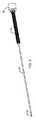
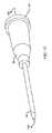
[0050]図1〜図16に示されているように、カテーテル挿入デバイス10の例示的な実施形態は、概して中空のハウジング12を有しており、概して中空のハウジング12は、開口した遠位端部16の反対側に閉じたベース端部14を有している。図1〜図3に示されているように、キャップ18が、遠位端部16に接続されて示されている。デバイスが使用される寸前に、キャップ18が除去され、それは、図4に示されているように、中空の針20を露出させる。 [0050] As shown in FIGS. 1-16, an exemplary embodiment of a
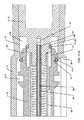
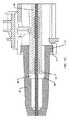
[0051]中空の針20は、近位針端部24の反対側に遠位皮膚穿刺端部22を有している。近位針端部24は、概して中空のハウジング12の閉じたベース端部14に移動不能に取り付けられており、近位針端部24は、図11Aに最良に示されているように、概して中空のハウジング12の中に配設されている。これらの実施形態では、針の近位針端部24は、近位ベース端部/針ベース76の中へ挿入されている。針ベース76は、ハウジング12の閉じたベース端部14の一部として形成され得、または、本明細書で示されているように、別々のパーツであることが可能である。図14および図14Aに示されているように、近位ベース端部/針ベース76は、孔部78を有しており、孔部78は、近位針端部24が装着され、および、固定して取り付けられるためのものである。次いで、針ベース76は、ハウジング12の閉じたベース端部14の中に恒久的に装着され、次いでそれを閉じる。針ベース76は、ハウジング12に接着され、もしくは結合され得、または、代替的に、締まり嵌めであることが可能であり、または、さらに別の代替例として、それらは、オス−メスねじ山付き端部を用いて互いにねじ込まれ得る。本明細書で示されているように、針ベース76は、別々のパーツとして構成される。その理由は、次いで、針ベース76の中にアパーチャー38を設置することがより容易であるからである。このアパーチャー38は、デバイスの動作の間に真空が伝達されるための経路を生成させるので、本発明の重要な態様である。そのうえ、近位針端部24は、ハウジング12の針ベース76/閉じたベース端部14に接着され、結合され、成形され、ねじ込まれ、または、締まり嵌めによって取り付けられ得る。 [0051] The
[0052]図4に示されているように、中空の針20の遠位皮膚穿刺端部22は、概して中空のハウジング12の開口した遠位端部16を越えて延在している。中空の針20は、遠位皮膚穿刺端部22と近位針端部24との間で流体連通または空気圧連通しているチャネル26を画定している。次いで、プランジャー28が、中空の針20の少なくとも一部分の上にスライド可能に配設されている。プランジャー28は、針20に沿ってスライドし、または、プランジャー28は、針に沿って並進もしくは移動するということが可能である。また、本明細書で示されているように、プランジャー28は、針20の周りで回転することが可能であるが、回転は、必要な要件ではない。たとえば、プランジャー28およびハウジング12は、本明細書で示されている円形バージョンと比較して、正方形様式または長方形様式で構成され得る。組み立て時および使用時の配向は重要でないので、円形バージョンを製造および組み立てることは、単に、より容易である。 [0052] As shown in FIG. 4, the distal
[0053]プランジャー28は、プランジャー遠位端部32の反対側にプランジャー近位チャンバー端部30を含む。中空の針20の遠位皮膚穿刺端部22は、プランジャー遠位端部32を通って延在している。図11Aおよび図11Bに最良に示されているように、拡張可能なチャンバー34は、プランジャー近位チャンバー端部30、および、概して中空の針20の閉じたベース端部の少なくとも内側表面36によって、少なくとも部分的に形成されている。拡張可能なチャンバー34は、近位針端部24を通して中空の針20のチャネル26と流体連通または空気圧連通しており、近位針端部24において、アパーチャー/孔部38が位置付けされ得る。拡張可能なチャンバー34は、プランジャー28が中空の針20の遠位皮膚穿刺端部22に向かって移動するときに、体積が増加するように構成されている。 [0053] The
[0054]第1のシール40が、プランジャー28の内側表面42、または、概して中空のハウジング12/針ベース76のいずれかに取り付けられている。第2のシール44が、プランジャー28の外側表面46、または、概して中空のハウジング12のいずれかに取り付けられている。第1のシール40は、プランジャー28がその最も近位の位置にあるときに、プランジャーの内側表面42と概して中空のハウジング12/針ベース76との間をシールするように構成されており、第2のシール44は、プランジャー28がその最も近位の位置にあるときに、プランジャーの外側表面46と概して中空のハウジング12との間をシールするように構成されている。本明細書で示されているように、それぞれのシールは、その断面が、長方形、正方形、または円形であることにかかわらず、Oリングまたは他の適切な構造体であることが可能である。それぞれのシールをその要求される位置に維持するために、それぞれのシールが、チャネルの中へ組み立てられた。たとえば、針ベース76は、第1のシール40を捕獲する円周方向のチャネル80を有している。また、プランジャー28は、第2のシール44を捕獲するための円周方向のチャネル82を有している。当業者によって理解され得るように、チャネル80および82は、反対表面の上に形成され得、デバイスは、同様に機能することとなる。そのうえ、チャネルは、除去され得、デバイスは、同様に機能することとなる。 [0054] A
[0055]スプリング48は、概して中空のハウジング12/針ベース76とプランジャー28との間に機械的に係合されている。スプリング48は、中空の針20の遠位皮膚穿刺端部22に向けてプランジャー28を付勢する。カテーテル50は、中空の針20の少なくとも第2の部分の上にスライド可能に配設されており、中空の針20の遠位皮膚穿刺端部22は、カテーテル50の遠位挿入端部52を通って延在している。カテーテル50は、近位接続端部54の反対側に遠位挿入端部52を含み、カテーテル50の近位接続端部54は、プランジャー遠位端部32の隣に配設されるように構成されている。 [0055] The
[0056]ボタン56が、プランジャー28に移動不能に取り付けられており、また、概して中空のハウジング12の外側に延在している。ハウジング12は、J字形状のスロット58を含むことが可能であり、ボタン56は、保管位置60、アームド位置62、および、延長位置64の間で、J字形状のスロット58の中で移動可能であるように構成されている。これは、図16に最良に示されている。保管位置60は、ボタンがJ字形状のスロット58の下側端部に位置付けされている場合である。アームド位置62は、プランジャー28がJ字形状のスロットの最底部にあるその最も近位の位置まで移動させられている場合である。延長位置64は、プランジャー28がその最も遠位の位置まで移動させられている場合である。 [0056] A
[0057]ボタン56は、完全に除去され得、または、さらには別のパーツの上に再配置され得るが、本発明は依然として適正に機能するように構成されることとなるということを、当業者は理解することとなる。たとえば、ボタン56は、ハウジング12の上に一体化され得、プランジャー28の移動を依然として制御することが可能である。そのうえ、J字形状のスロット58の形状は、また修正され、または、さらには除去され得る。たとえば、プランジャー28は、製造の間に最初から組み込まれ得る。次いで、ユーザーは、遠位皮膚穿刺端部22が患者の皮膚に侵入すると、ボタン56を押すこととなり、または、ある種のリリースに係合することとなる。したがって、この実施形態では、スロットは、完全に除去されている。 [0057] It will be appreciated that the
[0058]キャップ18がデバイス10の上にあるとき、ボタン56は、保管位置60まで移動させられている。これは、スプリング48が圧縮されており、内部付勢がデバイスの中にすでに存在しているということを意味している。保管位置60は、図11Aの断面図に対応している。保管位置60では、シール40および42は、2つの表面と接触していないということに留意することが重要である。構造体は、シールがそれらのそれぞれのチャネルの中で単に捕獲されているだけであるというように設計されている。これは、重要である。その理由は、シールがある量の静止摩擦または粘性を生成させ、それが、デバイスが正しく動作することを妨げる可能性があるからである。シールがゴムまたはゴム状の材料から作製されているとしても、シールは流体のように流れる傾向があるということが発見された。長期間にわたり2つの表面の間に設置されている場合には、それらは2つの表面をくっつけて保持する傾向がある。これは、それらが長期間にわたり2つの表面の間に保管されていた場合には、デバイス10の適正な動作を妨害することとなる。したがって、保管位置60では、シールは、それらの第2の表面に対してシールしていないが、むしろ、シールとして利用されるように準備されたそれらのプライマリーチャネルの中で捕獲されている。 [0058] When the
[0059]次いで、図11Bは、アームド位置62に対応しており、アームド位置62では、キャップ18が除去されており、プランジャー28は、ボタン56を通してユーザーによって後退させられている。次いで、ユーザーは、針20の遠位皮膚穿刺端部22を挿入し、ボタン56から手を放すことが可能である。図11Bに見ることができるように、拡張可能なチャンバー34は、実質的にゼロの体積または非常に小さい体積を有している。シール40および42は、拡張可能なチャンバー34の体積を生成させて画定することを助ける。空気または流体は、針ベース76の中のアパーチャー38を通して、拡張可能なチャンバー34まで、針20のチャネル26の中で連通状態にあり、それは、自由に流れることが可能であるということを意味している。 [0059] FIG. 11B then corresponds to the armed position 62, where the
[0060]ユーザーが患者の組織の中で針20を前進させると、遠位皮膚穿刺端部22は、静脈または動脈の中へ最終的に刺さることとなる。これが起こるとき、血液、流体、または空気は、次いで、チャネル26の中へ流入することが可能であり、拡張可能なチャンバー34が拡張することを可能にする。次いで、これは、プランジャー28が前方へ前進しているということを意味している。ここで、ボタン56は延長位置までスライドすることができるので、スプリング48は、プランジャー28を前方へかなりの距離にわたり推進させることができる。J字形状のスロット58の上部が開口しており、それは、ボタン56がそれを通過することができ、前方へ移動することを維持することができるということを意味している。プランジャー28は、前方へ推進させられ、それは、カテーテル50を前方へ、静脈または動脈の中へ押す。次いで、ユーザーは、次いで、デバイス10を引き出すときに、ソフトカテーテル50をずっと押し、カテーテル50を患者の中へ挿入された状態に残すことが可能である。 [0060] As the user advances the
[0061]カテーテル50は、非常に可撓性の遠位挿入端部52を有しており、非常に可撓性の遠位挿入端部52は、静脈または動脈の中に残るように設計されている。次いで、カテーテル50の近位接続端部54は、医師によって必要とされるように、様々な他の薬物送達デバイスまたはサンプル抽出デバイスに接続され得る。 [0061]
[0062]ここで図11Cを参照すると、アームド位置62では、小さいギャップ66が存在しており、小さいギャップ66は、カテーテル内側表面68とプランジャー遠位端部32との間に生成されているということが留意される。このギャップ66は、プランジャー28がカテーテル50に係合する前に、プランジャー28が移動を始めるためのスペースを生成させるので、このギャップ66は重要である。移動するコンポーネントの運動量は、デバイスが最適に動作するのに好適である。拡張可能なチャンバー34の中の真空が破壊された後に、制限されない移動が生成される。プランジャー28は、スプリング48によって前方へ推進し、ギャップ66の間の運動量を生成させることが可能である。次いで、プランジャー28がカテーテルの内側表面68に突き当たると、プランジャー28は、カテーテル50を前方へ推進させることが可能である。設計が変更され得、カテーテル50の近位接続端部54などの異なる場所で、プランジャー28がカテーテル50にぶつかるということが当業者によって理解される。 [0062] Referring now to FIG. 11C, in the armed position 62, there is a
[0063]図11Cに見ることができるように、カテーテル50は、その近位接続端部54において、ハウジング12の開口した遠位端部16に緩く保持されている。これは、キャップ18が除去されるときに、カテーテル50がスライドせず、針20から落下しないということを確実にするためである。また、これは、プランジャー28がアームド位置62へ後退させられるときに、ハウジング12の閉じたベース端部14に向かうカテーテル50の移動を防止するために使用される。 [0063] As can be seen in FIG. 11C, the
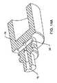
[0064]図10Aおよび図10Bに最良に見ることができるように、プランジャー28は、円周方向凹部70を有することが可能であり、円周方向凹部70は、プランジャー28が針ガードとして機能が倍になることを可能にする。概して中空のハウジング12は、遠位係合先端部74を有する針ガードフレキシャー72を有している。プランジャー28が延長位置64にあるときに、ハウジング12の遠位係合先端部74は、プランジャー28の円周方向凹部70の中に捕獲される。次いで、プランジャー28は、中空の針12およびハウジング12との関連で固定して装着される。プランジャー遠位端部32は、中空の針20の遠位皮膚穿刺端部22を越えて位置決めされており、中空の針20の遠位皮膚穿刺端部22をカバーしている。 [0064] As can best be seen in FIGS. 10A and 10B, the
[0065]デバイス10を適正に働かせるために、この新規な構造体の中に作用するすべての力の間の最適なバランスが存在するはずであるということが認識されることとなる。スプリング定数は、動脈または静脈に到達したときに、プランジャー28を前方へ前進させるのに十分であるが強力すぎないように形成されなければならず、強力すぎる場合には、それは、拡張可能なチャンバー34の中の真空を時期尚早に圧倒し、カテーテル50を時期尚早に配備する。また、シール40、44の摩擦力は、動脈、静脈、潜在的なスペース、または流体で充填されたキャビティーに到達したときに、スプリング48がプランジャー28を前方へ前進させることができないような高すぎるものであってはならない。これは、シール40および44が、保管位置60での保管の間に自由になっており、次いで、アームド位置62において係合されることを、J字形状のスロット58が可能にするのはなぜかということである。これは、シールが表面に当接してくっつく状態に流れることを防止する。たとえば、保管の間にシールが係合された場合には、製品が長く保管されればされるほど、シールはよりくっつくこととなる。本発明が適正に働くための力の繊細なバランスに起因して、アームド位置または同様の位置にシールを保管することは、カテーテル挿入デバイス10の機能性を損なう可能性がある。 [0065] It will be appreciated that there must be an optimal balance between all forces acting in this new structure in order for the
[0066]テストの間に、本明細書で使用される好適なスプリングは、延長されるときに、約0.002500kg/mm(約0.140ポンド/インチ)の計算されたスプリング定数を有した。計算された最大安全負荷は、約68.555mm(約2.699インチ)のトラベルに相当する0.801の圧縮された(隙間のない)高さにおいて、約0.1715kg(約0.378ポンド)であった。より具体的には、本明細書で使用される別のスプリングは、0.2286mm(0.009インチ)厚さのピアノ線を用いて、3.048mm(0.120インチ)の外径を有し、約88.9mm(約3.50インチ)自由長さを備えていた。スプリングは、約97.54の合計コイルを有しており、それは、約0.0364ピッチであった。この好適なスプリングのスプリング定数は、0.001121kg/mm(0.0628ポンド/インチ)であった。スプリングの端部は、閉じられており、研磨されていなかった。仕上げは、無地仕上げであった。当業者は、これらの好適なスプリング実施形態からの多くの変形例が、デバイス10に関して可能であるということを理解することとなる。本明細書で開示されている値は、たとえば、プラスマイナス10パーセントの範囲にあり、または、さらにはプラスマイナス25パーセントの範囲にあることも可能である。たとえば、当業者は、0.00893kg/mm(0.50ポンド/インチ)未満の、または、好ましくは0.00446kg/mm(0.25ポンド/インチ)未満の、または、好ましくは0.002232kg/mm(0.125ポンド/インチ)未満の定格のスプリングを使用することが可能である。また、例として、スプリングは、6.35mm(0.25インチ)未満の、または、好ましくは3.175mm(0.125インチ)未満の外径を有することが可能である。 [0066] During testing, the preferred springs used herein had a calculated spring constant of about 0.002500 kg / mm (about 0.140 lb / inch) when extended. . The calculated maximum safe load is about 0.178 kg (about 0.378 lbs) at a compressed (clearance) height of 0.801 corresponding to about 68.555 mm (about 2.699 inches) travel. )Met. More specifically, another spring as used herein has an outer diameter of 3.048 mm (0.120 inch) using a piano wire that is 0.2286 mm (0.009 inch) thick. And a free length of about 88.9 mm (about 3.50 inches). The spring had a total coil of about 97.54, which was about 0.0364 pitch. The spring constant of this preferred spring was 0.001121 kg / mm (0.0628 lb / in). The end of the spring was closed and not polished. The finish was a solid finish. Those skilled in the art will appreciate that many variations from these preferred spring embodiments are possible for the
[0067]本発明の新規の特徴は、設計の簡潔さである。この構造は、単に1つのスプリング48の使用を必要とするだけである。そのうえ、単に2つのシール40および44だけが存在し、拡張可能なチャンバー34の中に真空を生成させるために使用されている。また、そのうえ、プランジャー28は、針ガードとしても作用し、構造をさらに簡単化している。 [0067] A novel feature of the present invention is the simplicity of the design. This structure only requires the use of a
[0068]図16および図16Aに最良に見ることができるように、J字形状のスロット58がハウジングの中に形成されるように、また、針ガードフレキシャー72がハウジングの中に形成されるように、ハウジングは形成されている。これは、余分なパーツが必要とされないので、パーツ点数を簡単化する。図12および図13に最良に見ることができるように、プランジャー28は、様々なスロットおよびカットアウトを備えて形成されており、それは、簡単な2つのパーツ金型の中で作製され得るようになっている。そのうえ、ボタン56および円周方向凹部70は、その中に一体化されており、パーツ点数を低減させることによって設計をさらに単純化する。 [0068] As best seen in FIGS. 16 and 16A, a J-shaped slot 58 is formed in the housing and a
[0069]いくつかの実施形態が、図示目的のために詳細に説明されてきたが、様々な修正例が、本発明の範囲および精神から逸脱することなく、それぞれ作製され得る。したがって、本発明は、添付の特許請求の範囲以外によっては、限定されるべきではない。 [0069] Although several embodiments have been described in detail for purposes of illustration, various modifications can each be made without departing from the scope and spirit of the invention. Accordingly, the invention should not be limited except as by the appended claims.
Claims (24)
Translated fromJapanese前記中空の針の少なくとも一部分の上にスライド可能に配設されているプランジャーであって、前記中空の針の前記遠位皮膚穿刺端部は、前記プランジャーの遠位端部を通って延在している、プランジャーと、
前記中空の針の前記近位ベース端部の少なくとも一部分と前記プランジャーの一部分との間に機械的に係合されているスプリングであって、前記スプリングは、前記中空の針の前記遠位皮膚穿刺端部に向けて前記プランジャーを付勢している、スプリングと、
前記中空の針の少なくとも第2の部分の上にスライド可能に配設されているカテーテルであって、前記中空の針の前記遠位皮膚穿刺端部は、前記カテーテルの遠位挿入端部を通って延在しており、前記カテーテルは、近位接続端部の反対側に前記遠位挿入端部を含み、前記カテーテルの前記近位接続端部は、前記プランジャーの前記遠位端部の隣に配設されるように構成されている、カテーテルと、
前記中空の針の前記チャネルと流体連通または空気圧連通している第1の開口部を有する拡張可能なチャンバーであって、前記拡張可能なチャンバーは、前記中空の針の前記近位ベース端部および前記プランジャーの近位端部によって少なくとも部分的に形成されており、前記拡張可能なチャンバーは、前記プランジャーが前記中空の針の前記遠位皮膚穿刺端部に向かって移動するときに、体積が増加するように構成されている、拡張可能なチャンバーと
を含む、カテーテル挿入デバイス。A hollow needle having a distal skin puncture end opposite the proximal base end, wherein the hollow needle is in fluid communication between the distal skin puncture end and the proximal base end. Or a hollow needle defining a channel in pneumatic communication;
A plunger slidably disposed on at least a portion of the hollow needle, the distal skin piercing end of the hollow needle extending through the distal end of the plunger. The existing plunger,
A spring mechanically engaged between at least a portion of the proximal base end of the hollow needle and a portion of the plunger, the spring being the distal skin of the hollow needle A spring urging the plunger toward the puncture end;
A catheter slidably disposed over at least a second portion of the hollow needle, wherein the distal skin puncture end of the hollow needle passes through a distal insertion end of the catheter. And the catheter includes the distal insertion end opposite the proximal connection end, the proximal connection end of the catheter extending from the distal end of the plunger. A catheter configured to be disposed adjacent to;
An expandable chamber having a first opening in fluid or pneumatic communication with the channel of the hollow needle, the expandable chamber comprising the proximal base end of the hollow needle and Formed at least in part by the proximal end of the plunger, wherein the expandable chamber has a volume when the plunger moves toward the distal skin puncture end of the hollow needle. A catheter insertion device comprising an expandable chamber configured to increase.
近位針端部の反対側に遠位皮膚穿刺端部を有する中空の針であって、前記近位針端部は、前記中空のハウジングの前記閉じたベース端部に移動不能に取り付けられており、前記近位針端部は、前記中空のハウジングの中に配設されており、前記中空の針の前記遠位皮膚穿刺端部は、前記中空のハウジングの前記開口した遠位端部を越えて延在しており、前記中空の針は、前記遠位皮膚穿刺端部と前記近位針端部との間で流体連通または空気圧連通しているチャネルを画定している、中空の針と、
前記中空の針の少なくとも一部分の上にスライド可能に配設されているプランジャーであって、前記プランジャーは、プランジャー遠位端部の反対側にプランジャー近位チャンバー端部を含み、前記中空の針の前記遠位皮膚穿刺端部は、前記プランジャー遠位端部を通って延在している、プランジャーと、
前記プランジャー近位チャンバー端部、および、前記中空の針の前記閉じたベース端部の少なくとも内側表面によって、少なくとも部分的に形成されている拡張可能なチャンバーであって、前記拡張可能なチャンバーは、前記近位針端部を通して、前記中空の針の前記チャネルと流体連通または空気圧連通しており、前記拡張可能なチャンバーは、前記プランジャーが前記中空の針の前記遠位皮膚穿刺端部に向かって移動するときに、体積が増加するように構成されている、拡張可能なチャンバーと、
第1のシールおよび第2のシールであって、前記第1のシールは、前記プランジャーの内側表面または前記中空のハウジングのいずれかに取り付けられており、前記第2のシールは、前記プランジャーの外側表面または前記中空のハウジングのいずれかに取り付けられており、前記第1のシールは、前記プランジャーがその最も近位の位置にあるときに、前記プランジャーの前記内側表面と前記中空のハウジングとの間をシールするように構成されており、前記第2のシールは、前記プランジャーがその最も近位の位置にあるときに、前記プランジャーの前記外側表面と前記中空のハウジングとの間をシールするように構成されている、第1のシールおよび第2のシールと、
前記中空のハウジングと前記プランジャーとの間に機械的に係合されているスプリングであって、前記スプリングは、前記中空の針の前記遠位皮膚穿刺端部に向けて前記プランジャーを付勢している、スプリングと、
前記中空の針の少なくとも第2の部分の上にスライド可能に配設されているカテーテルであって、前記中空の針の前記遠位皮膚穿刺端部は、前記カテーテルの遠位挿入端部を通って延在しており、前記カテーテルは、近位接続端部の反対側に前記遠位挿入端部を含み、前記カテーテルの前記近位接続端部は、前記プランジャー遠位端部の隣に配設されるように構成されている、カテーテルと
を含む、カテーテル挿入デバイス。And an empty housingamong that having a base end portion closed on the opposite side of the open distal end,
On the opposite side of the Kinkuraiharitan part a hollow needle having a distal skin-piercing end portion, the proximal needle end, attached immovably on said closed base end portion of the frontSL in empty housing is and the proximal needle end is disposed in the frontSL in an empty housing, the distal skin-piercing end portion of the hollow needle, the opening of thepre-SL in empty housing And the hollow needle defines a channel in fluid or pneumatic communication between the distal skin puncture end and the proximal needle end. A hollow needle,
A plunger slidably disposed on at least a portion of the hollow needle, the plunger including a plunger proximal chamber end opposite the plunger distal end; The distal skin piercing end of a hollow needle extends through the plunger distal end; and a plunger;
It said plunger proximal chamber edge, and, by at least an inner surface of the closed base end of the frontSL in the empty needle, and an expandable chamber that is at least partially formed, which can be the extension A chamber is in fluid or pneumatic communication with the channel of the hollow needle through the proximal needle end, and the expandable chamber is configured such that the plunger is the distal skin puncture end of the hollow needle. An expandable chamber configured to increase in volume when moving toward a section;
A first seal and second seal, the first seal, said attached to either the inner surface or the previousSL in empty housing of the plunger, the second seal, thein the outer surface or previousSL plunger is attached to one of the empty housing, said first seal when said plunger is in position in its most proximal, said inner surface of said plunger when being configured to seal between thepre-SL in an empty housing, said second seal when said plunger is in the position of the proximal-most and the outer surface of said plunger is configured to seal between thepre-SL in an empty housing, the first and second seals,
A spring is mechanically engaged between the frontSL in an empty housing and the plunger, the spring, the plunger toward the distal skin-piercing end portion of the hollow needle Energizing the spring,
A catheter slidably disposed over at least a second portion of the hollow needle, wherein the distal skin puncture end of the hollow needle passes through a distal insertion end of the catheter. The catheter includes the distal insertion end opposite the proximal connection end, the proximal connection end of the catheter next to the plunger distal end. A catheter insertion device comprising a catheter configured to be disposed.
ハウジング近位端部の反対側に開口した遠位端部を有する中空のハウジングであって、前記針ベースは、前記ハウジング近位端部に移動不能に取り付けられている、中空のハウジングと、
前記細長い中空の針の少なくとも一部分の上に並進可能に配設されているプランジャーであって、前記遠位皮膚穿刺端部は、プランジャー遠位端部を通って延在している、プランジャーと、
前記プランジャーと前記ハウジング近位端部または前記針ベースのいずれかとの間に機械的に係合されているスプリングであって、前記スプリングは、前記遠位皮膚穿刺端部に向けて前記プランジャーを付勢するように構成されている、スプリングと、
前記細長い中空の針の少なくとも第2の部分の上に並進可能に配設されているカテーテルであって、前記カテーテルは、近位接続端部の反対側に遠位挿入端部を含み、前記遠位皮膚穿刺端部は、前記カテーテルの前記遠位挿入端部を通って延在しており、前記カテーテルの前記近位接続端部は、前記プランジャー遠位端部の隣に配設されるように構成されている、カテーテルと、
前記プランジャーの近位プランジャー端部、前記針ベースの外側表面、および、前記ハウジング近位端部の内側表面によって形成されている拡張可能なチャンバーであって、前記拡張可能なチャンバーは、前記プランジャーの並進移動に従って体積が変化する、拡張可能なチャンバーと、
前記針ベースの前記外側表面の周りに配設されている第1のシールと、
前記プランジャーの外側表面の周りに配設されている第2のシールと
を含む、カテーテル挿入デバイス。An elongate hollow needle having a distal skin puncture end opposite the proximal needle end, the proximal needle end being immovably secured to a needle base, the elongate hollow needle being An elongate hollow needle defining a channel in fluid or pneumatic communication between the distal skin piercing end and the proximal needle end;
A empty housingin that having a distal end which opens to the opposite side of the housing proximal end, the needle base, the housing is mounted immovably to the proximalend, middle empty A housing;
A plunger that is translatably disposed on at least a portion of the elongated hollow needle, the distal skin piercing end extending through the plunger distal end. Jar,
A spring mechanically engaged between the plunger and either the proximal end of the housing or the needle base, the spring toward the distal skin piercing end A spring configured to bias
A catheter that is translatably disposed over at least a second portion of the elongated hollow needle, the catheter including a distal insertion end opposite the proximal connection end; A distal skin piercing end extends through the distal insertion end of the catheter, and the proximal connecting end of the catheter is disposed next to the plunger distal end. A catheter configured as;
An expandable chamber formed by a proximal plunger end of the plunger, an outer surface of the needle base, and an inner surface of the housing proximal end, the expandable chamber comprising: An expandable chamber whose volume changes according to the translation of the plunger;
A first seal disposed about the outer surface of the needle base;
And a second seal disposed about the outer surface of the plunger.
近位針端部の反対側に遠位皮膚穿刺端部を有する中空の針であって、前記中空の針は、前記遠位皮膚穿刺端部と前記近位針端部との間で流体連通または空気圧連通しているチャネルを画定しており、前記近位針端部は、前記ハウジングベース端部に移動不能に取り付けられており、前記中空の針の前記遠位皮膚穿刺端部は、前記中空のハウジングの前記開口した遠位端部を越えて延在している、中空の針と、
前記中空の針の少なくとも一部分の上にスライド可能に配設されているプランジャーであって、前記プランジャーは、プランジャー遠位端部の反対側にプランジャー近位端部を含み、前記中空の針の前記遠位皮膚穿刺端部は、前記プランジャー遠位端部を通って延在している、プランジャーと、
前記中空のハウジングと前記プランジャーとの間に機械的に係合されているスプリングであって、前記スプリングは、前記中空の針の前記遠位皮膚穿刺端部に向けて前記プランジャーを付勢している、スプリングと
を含む、カテーテル挿入デバイスであって、
拡張可能なチャンバーが、前記プランジャー近位端部および前記ハウジングベース端部の内側表面によって少なくとも部分的に画定されており、前記拡張可能なチャンバーは、前記中空の針の前記チャネルと流体連通または空気圧連通しており、前記拡張可能なチャンバーは、前記プランジャーが前記中空の針の前記遠位皮膚穿刺端部に向かって移動するときに、体積が増加するように構成されている、カテーテル挿入デバイス。Andincluding the middle empty housing distal end which opens to the opposite side of the housing base end,
A hollow needle having a distal skin puncture end opposite the proximal needle end, wherein the hollow needle is in fluid communication between the distal skin puncture end and the proximal needle end. Or defining a channel in pneumatic communication, wherein the proximal needle end is immovably attached to the housing base end, and the distal skin piercing end of the hollow needle isserial in and extends beyond the distal end portion which is the opening of the empty housing, a hollow needle,
A plunger slidably disposed on at least a portion of the hollow needle, the plunger including a plunger proximal end opposite the plunger distal end; The distal skin puncture end of the needle extends through the plunger distal end; and
A spring is mechanically engaged between the frontSL in an empty housing and the plunger, the spring, the plunger toward the distal skin-piercing end portion of the hollow needle A catheter insertion device including a spring biasing,
An expandable chamber is at least partially defined by the plunger proximal end and the inner surface of the housing base end, the expandable chamber in fluid communication with the channel of the hollow needle or Catheter insertion, in pneumatic communication, wherein the expandable chamber is configured to increase in volume as the plunger moves toward the distal skin puncture end of the hollow needle. device.
Applications Claiming Priority (5)
| Application Number | Priority Date | Filing Date | Title |
|---|---|---|---|
| US201361844349P | 2013-07-09 | 2013-07-09 | |
| US61/844,349 | 2013-07-09 | ||
| US14/326,088US9433758B2 (en) | 2013-07-09 | 2014-07-08 | Intravascular catheter insertion device |
| US14/326,088 | 2014-07-08 | ||
| PCT/US2014/045837WO2015006383A2 (en) | 2013-07-09 | 2014-07-09 | Intravascular catheter insertion device |
Publications (2)
| Publication Number | Publication Date |
|---|---|
| JP2016523681A JP2016523681A (en) | 2016-08-12 |
| JP6419175B2true JP6419175B2 (en) | 2018-11-07 |
Family
ID=52277677
Family Applications (1)
| Application Number | Title | Priority Date | Filing Date |
|---|---|---|---|
| JP2016525439AExpired - Fee RelatedJP6419175B2 (en) | 2013-07-09 | 2014-07-09 | Intravascular catheter insertion device |
Country Status (6)
| Country | Link |
|---|---|
| US (1) | US9433758B2 (en) |
| EP (1) | EP3019230B1 (en) |
| JP (1) | JP6419175B2 (en) |
| AU (1) | AU2014287391A1 (en) |
| CA (1) | CA2917328C (en) |
| WO (1) | WO2015006383A2 (en) |
Families Citing this family (6)
| Publication number | Priority date | Publication date | Assignee | Title |
|---|---|---|---|---|
| US8323249B2 (en) | 2009-08-14 | 2012-12-04 | The Regents Of The University Of Michigan | Integrated vascular delivery system |
| WO2011146769A2 (en) | 2010-05-19 | 2011-11-24 | Tangent Medical Technologies Llc | Integrated vascular delivery system |
| US8814833B2 (en) | 2010-05-19 | 2014-08-26 | Tangent Medical Technologies Llc | Safety needle system operable with a medical device |
| CA2937744C (en) | 2014-02-04 | 2022-08-09 | Icu Medical, Inc. | Self-priming systems and methods |
| EP3597258B1 (en)* | 2017-03-16 | 2025-09-03 | Terumo Kabushiki Kaisha | Catheter assembly |
| US11464943B2 (en)* | 2019-11-12 | 2022-10-11 | Becton, Dickinson And Company | Assisted catheter advancement |
Family Cites Families (68)
| Publication number | Priority date | Publication date | Assignee | Title |
|---|---|---|---|---|
| US4439185A (en)* | 1981-10-21 | 1984-03-27 | Advanced Cardiovascular Systems, Inc. | Inflating and deflating device for vascular dilating catheter assembly |
| US4487605A (en) | 1982-11-17 | 1984-12-11 | Critikon, Inc. | Flashback device for catheters |
| US4906236A (en) | 1988-08-29 | 1990-03-06 | Alberts David S | Self-sheathing hypodermic needle |
| US4944728A (en) | 1988-10-17 | 1990-07-31 | Safe Medical Devices, Inc. | Intravenous catheter placement device |
| US4966589A (en) | 1988-11-14 | 1990-10-30 | Hemedix International, Inc. | Intravenous catheter placement device |
| US5407431A (en) | 1989-07-11 | 1995-04-18 | Med-Design Inc. | Intravenous catheter insertion device with retractable needle |
| US5195985A (en) | 1990-05-25 | 1993-03-23 | Hall John E | Syringe having a retractable needle |
| US5330432A (en) | 1991-12-06 | 1994-07-19 | Inbae Yoon | Retractable safety penetrating instrument |
| US5186712A (en) | 1991-08-23 | 1993-02-16 | Kansas Creative Devices, Inc. | Intravenous catheter launching device |
| US5312361A (en) | 1991-09-13 | 1994-05-17 | Zadini Filiberto P | Automatic cannulation device |
| US5230706A (en)* | 1992-03-12 | 1993-07-27 | Duquette Irene A | Bi-directional valve assembly used in needleless injection or infusion ports |
| US5300046A (en) | 1992-03-30 | 1994-04-05 | Symbiosis Corporation | Thoracentesis sheath catheter assembly |
| US5334159A (en) | 1992-03-30 | 1994-08-02 | Symbiosis Corporation | Thoracentesis needle assembly utilizing check valve |
| US5527290A (en) | 1992-08-10 | 1996-06-18 | Zadini; Filiberto | Semi-automatic cannulation device or manually triggered self-propelled catheter cannulation device |
| US5415177A (en) | 1992-12-31 | 1995-05-16 | Zadini; Filiberto P. | Automatic guide wire placement device for intravascular catheters |
| US5411486A (en) | 1993-07-21 | 1995-05-02 | Zadini; Filiberto | Needle stick protector for automatic cannulation devices |
| US6280401B1 (en) | 1993-08-23 | 2001-08-28 | Sakharam D. Mahurkar | Hypodermic needle assembly |
| US5836921A (en) | 1993-08-23 | 1998-11-17 | Mahurkar; Sakharam D. | Hypodermic needle assembly |
| US5527291A (en) | 1994-05-24 | 1996-06-18 | Zadini; Filiberto P. | Manual catheter placement device |
| CA2168615A1 (en) | 1995-03-07 | 1996-09-08 | Timothy J. Erskine | Catheter-advancement actuated needle retraction system |
| US5795339A (en) | 1995-03-07 | 1998-08-18 | Becton Dickinson And Company | Catheter-advancement actuated needle retraction system |
| US5591138A (en)* | 1995-08-10 | 1997-01-07 | Vaillancourt; Vincent L. | Protected needle assembly |
| US5749371A (en) | 1995-10-06 | 1998-05-12 | Zadini; Filiberto P. | Automatic guidewire placement device for medical catheters |
| US5749856A (en) | 1995-11-24 | 1998-05-12 | Zadini; Filiberto P. | Needle stick protective apparatus for manual catheter placement devices |
| US6287322B1 (en) | 1995-12-07 | 2001-09-11 | Loma Linda University Medical Center | Tissue opening locator and everter and method |
| ATE481124T1 (en) | 1996-02-27 | 2010-10-15 | Braun Melsungen Ag | NEEDLE TIP PROTECTION FOR SUBCUTANEOUS INJECTIONS |
| US6629959B2 (en) | 1996-02-27 | 2003-10-07 | Injectimed, Inc. | Needle tip guard for percutaneous entry needles |
| US5879337A (en) | 1997-02-27 | 1999-03-09 | Injectimed, Inc. | Needle tip guard for hypodermic needles |
| US5865806A (en) | 1996-04-04 | 1999-02-02 | Becton Dickinson And Company | One step catheter advancement automatic needle retraction system |
| US5755709A (en) | 1996-04-25 | 1998-05-26 | Cuppy; Michael J. | Catheter system for percutaneously introducing a liquid |
| US6197001B1 (en) | 1996-09-27 | 2001-03-06 | Becton Dickinson And Company | Vascular access device |
| US5800395A (en)* | 1996-12-05 | 1998-09-01 | Mdc Investment Holdings, Inc. | Medical device with retractable needle |
| CA2275249C (en) | 1997-01-30 | 2004-03-23 | Boston Scientific Corporation | Pneumatically actuated tissue sampling device |
| US6607509B2 (en) | 1997-12-31 | 2003-08-19 | Medtronic Minimed, Inc. | Insertion device for an insertion set and method of using the same |
| US6277100B1 (en) | 1997-07-17 | 2001-08-21 | Medical Components, Inc. | Catheter guide wire introducing device and method |
| US6090078A (en) | 1997-09-30 | 2000-07-18 | Becton, Dickinson And Company | Dampening devices and methods for needle retracting safety vascular access devices |
| EP1030597B1 (en) | 1997-11-12 | 2007-02-28 | MDC Investment Holdings, Inc. | Fluid collection device with captured rectractable needle |
| US6210375B1 (en) | 1998-09-30 | 2001-04-03 | Becton, Dickinson And Company | Needle retraction mechanism with controlled retraction speed |
| US6217558B1 (en) | 1998-12-17 | 2001-04-17 | Filiberto P. Zadini | Apparatus for blood vessel type differentiation for syringes and guidewires placement devices |
| US6379337B1 (en) | 1998-12-22 | 2002-04-30 | Owais Mohammad M. B. B. S. | Retractable safety needles for medical applications |
| US6165136A (en) | 1998-12-23 | 2000-12-26 | Scimed Life Systems, Inc. | Semi-automatic biopsy device and related method of use |
| US6086563A (en) | 1999-01-13 | 2000-07-11 | Becton, Dickinson And Company | Needle retraction mechanism with push start retraction |
| US6626859B2 (en) | 2000-01-18 | 2003-09-30 | Coraflo Ltd. | High performance cannulas |
| US6398743B1 (en) | 2000-07-28 | 2002-06-04 | Mdc Investment Holdings, Inc. | Medical device for inserting a guide wire having a retractable needle |
| CN1523970A (en) | 2000-04-18 | 2004-08-25 | Mdc投资控股公司 | Medical device with retractable needle shield |
| US6478775B1 (en) | 2000-10-02 | 2002-11-12 | Genyx Medical Inc. | Device for delivering non-biodegradable bulking composition to a urological site |
| US20030120223A1 (en) | 2001-01-17 | 2003-06-26 | Von Segesser Ludwig K. | High performance cannulas |
| IL141574A0 (en) | 2001-02-21 | 2002-03-10 | Serpomed Ltd | Compact catheter insertion apparatus |
| US6796963B2 (en) | 2001-07-10 | 2004-09-28 | Myocardial Therapeutics, Inc. | Flexible tissue injection catheters with controlled depth penetration |
| US6835193B2 (en) | 2001-07-10 | 2004-12-28 | Myocardial Therapeutics, Inc. | Methods for controlled depth injections into interior body cavities |
| EP2422829B1 (en) | 2001-08-14 | 2013-03-06 | Applied Medical Resources Corporation | Surgical access sealing apparatus |
| US7294118B2 (en) | 2001-10-24 | 2007-11-13 | Becton, Dickinson And Company | Retractable needle assembly |
| US6984223B2 (en) | 2001-11-13 | 2006-01-10 | Becton, Dickinson And Company | Needle safety device |
| US20040030294A1 (en) | 2001-11-28 | 2004-02-12 | Mahurkar Sakharam D. | Retractable needle single use safety syringe |
| US6878129B2 (en) | 2001-12-21 | 2005-04-12 | Brigham And Women's Hospital | Atraumatic temporary arterial branch perfusion device |
| EP1386633A1 (en)* | 2002-08-02 | 2004-02-04 | Sergio Restelli | Safety catheter |
| EP1651121B1 (en) | 2003-07-07 | 2007-09-26 | CORAFLO Ltd liab. Co | High performance cannulas |
| US7850650B2 (en) | 2005-07-11 | 2010-12-14 | Covidien Ag | Needle safety shield with reset |
| US20060184105A1 (en) | 2005-02-15 | 2006-08-17 | Townsend Gregory L | Thin wall catheter and method of placing same |
| US7731692B2 (en) | 2005-07-11 | 2010-06-08 | Covidien Ag | Device for shielding a sharp tip of a cannula and method of using the same |
| ES2714385T3 (en) | 2006-03-01 | 2019-05-28 | Becton Dickinson Co | Controlled return for vascular access devices |
| US8066717B2 (en) | 2007-03-19 | 2011-11-29 | Restoration Robotics, Inc. | Device and method for harvesting and implanting follicular units |
| US8328738B2 (en) | 2007-06-29 | 2012-12-11 | Actuated Medical, Inc. | Medical tool for reduced penetration force with feedback means |
| DE102007049446A1 (en) | 2007-10-16 | 2009-04-23 | Cequr Aps | Catheter introducer |
| US8313493B2 (en) | 2008-07-10 | 2012-11-20 | Cook Medical Technologies Llc | Hydraulic guidewire advancement system |
| US8597252B2 (en) | 2010-07-15 | 2013-12-03 | Becton, Dickinson And Company | Removable flash chamber |
| CA2827044A1 (en) | 2011-02-10 | 2012-08-16 | Actuated Medical, Inc. | Medical tool with electromechanical control and feedback |
| US8414539B1 (en) | 2011-12-27 | 2013-04-09 | B. Braun Melsungen Ag | Needle tip guard for percutaneous entry needles |
- 2014
- 2014-07-08USUS14/326,088patent/US9433758B2/enactiveActive
- 2014-07-09EPEP14823025.3Apatent/EP3019230B1/enactiveActive
- 2014-07-09WOPCT/US2014/045837patent/WO2015006383A2/enactiveApplication Filing
- 2014-07-09JPJP2016525439Apatent/JP6419175B2/ennot_activeExpired - Fee Related
- 2014-07-09CACA2917328Apatent/CA2917328C/enactiveActive
- 2014-07-09AUAU2014287391Apatent/AU2014287391A1/ennot_activeAbandoned
Also Published As
| Publication number | Publication date |
|---|---|
| JP2016523681A (en) | 2016-08-12 |
| US20150018769A1 (en) | 2015-01-15 |
| EP3019230B1 (en) | 2019-09-04 |
| CA2917328C (en) | 2017-10-24 |
| WO2015006383A3 (en) | 2015-11-12 |
| CA2917328A1 (en) | 2015-01-15 |
| EP3019230A4 (en) | 2017-03-08 |
| US9433758B2 (en) | 2016-09-06 |
| WO2015006383A2 (en) | 2015-01-15 |
| EP3019230A2 (en) | 2016-05-18 |
| AU2014287391A1 (en) | 2016-01-28 |
Similar Documents
| Publication | Publication Date | Title |
|---|---|---|
| US12403294B2 (en) | Blood control for a catheter insertion device | |
| JP6419175B2 (en) | Intravascular catheter insertion device | |
| US10881833B2 (en) | Intravascular catheter insertion device | |
| US20210008347A1 (en) | Catheter assembly with segmented stabilization system | |
| JP4834757B2 (en) | Lure receiving vascular access system | |
| JP2020532366A (en) | Methods and devices for vascular access | |
| EP1926519B1 (en) | Cannula with introducer, needle protecting guard and blood collecting system | |
| TW200938241A (en) | An apparatus for peripheral vascular access | |
| JP2009537255A5 (en) | ||
| ES2220351T3 (en) | SELF-EMBOSSING SECURITY CATHETER. | |
| JP2004530517A (en) | Guidewire insertion device for catheter | |
| BRPI0510618B1 (en) | PRESSURE ACTIVATED PUNCTURE MEDICAL DEVICE | |
| US10136917B2 (en) | Intravascular catheter insertion device | |
| US11944766B2 (en) | Intravascular catheter insertion device | |
| KR101170757B1 (en) | Cam-actuated medical puncturing device and method | |
| JP7704737B2 (en) | Epidural device for detection and placement of needles in the epidural space - Patents.com | |
| EP1599143A2 (en) | System and method for rapid placement of chest tubes | |
| US20240285911A1 (en) | Intravascular catheter insertion device |
Legal Events
| Date | Code | Title | Description |
|---|---|---|---|
| A621 | Written request for application examination | Free format text:JAPANESE INTERMEDIATE CODE: A621 Effective date:20170710 | |
| A977 | Report on retrieval | Free format text:JAPANESE INTERMEDIATE CODE: A971007 Effective date:20180531 | |
| A131 | Notification of reasons for refusal | Free format text:JAPANESE INTERMEDIATE CODE: A131 Effective date:20180703 | |
| A521 | Request for written amendment filed | Free format text:JAPANESE INTERMEDIATE CODE: A523 Effective date:20180809 | |
| TRDD | Decision of grant or rejection written | ||
| A01 | Written decision to grant a patent or to grant a registration (utility model) | Free format text:JAPANESE INTERMEDIATE CODE: A01 Effective date:20180910 | |
| A61 | First payment of annual fees (during grant procedure) | Free format text:JAPANESE INTERMEDIATE CODE: A61 Effective date:20181009 | |
| R150 | Certificate of patent or registration of utility model | Ref document number:6419175 Country of ref document:JP Free format text:JAPANESE INTERMEDIATE CODE: R150 | |
| S111 | Request for change of ownership or part of ownership | Free format text:JAPANESE INTERMEDIATE CODE: R313113 | |
| R350 | Written notification of registration of transfer | Free format text:JAPANESE INTERMEDIATE CODE: R350 | |
| R250 | Receipt of annual fees | Free format text:JAPANESE INTERMEDIATE CODE: R250 | |
| R250 | Receipt of annual fees | Free format text:JAPANESE INTERMEDIATE CODE: R250 | |
| R250 | Receipt of annual fees | Free format text:JAPANESE INTERMEDIATE CODE: R250 | |
| LAPS | Cancellation because of no payment of annual fees |