JP6415704B2 - Medical device with removable swivel jaws - Google Patents
Medical device with removable swivel jawsDownload PDFInfo
- Publication number
- JP6415704B2 JP6415704B2JP2017514331AJP2017514331AJP6415704B2JP 6415704 B2JP6415704 B2JP 6415704B2JP 2017514331 AJP2017514331 AJP 2017514331AJP 2017514331 AJP2017514331 AJP 2017514331AJP 6415704 B2JP6415704 B2JP 6415704B2
- Authority
- JP
- Japan
- Prior art keywords
- jaws
- jaw
- housing
- medical device
- driver
- Prior art date
- Legal status (The legal status is an assumption and is not a legal conclusion. Google has not performed a legal analysis and makes no representation as to the accuracy of the status listed.)
- Active
Links
- 238000000034methodMethods0.000description9
- 229910052751metalInorganic materials0.000description8
- 239000002184metalSubstances0.000description8
- 229910001220stainless steelInorganic materials0.000description5
- 238000005452bendingMethods0.000description4
- 238000012986modificationMethods0.000description4
- 230000004048modificationEffects0.000description4
- 229910001000nickel titaniumInorganic materials0.000description4
- HLXZNVUGXRDIFK-UHFFFAOYSA-Nnickel titaniumChemical compound[Ti].[Ti].[Ti].[Ti].[Ti].[Ti].[Ti].[Ti].[Ti].[Ti].[Ti].[Ni].[Ni].[Ni].[Ni].[Ni].[Ni].[Ni].[Ni].[Ni].[Ni].[Ni].[Ni].[Ni].[Ni]HLXZNVUGXRDIFK-UHFFFAOYSA-N0.000description4
- -1polytetrafluoroethylenePolymers0.000description4
- 239000010935stainless steelSubstances0.000description4
- 229910045601alloyInorganic materials0.000description3
- 239000000956alloySubstances0.000description3
- 210000000078clawAnatomy0.000description3
- 230000023597hemostasisEffects0.000description3
- 230000002439hemostatic effectEffects0.000description3
- 239000004033plasticSubstances0.000description3
- 229920003023plasticPolymers0.000description3
- 230000007704transitionEffects0.000description3
- 208000012671Gastrointestinal haemorrhagesDiseases0.000description2
- 208000032843HemorrhageDiseases0.000description2
- 239000004698PolyethyleneSubstances0.000description2
- 239000000853adhesiveSubstances0.000description2
- 230000001070adhesive effectEffects0.000description2
- 230000000740bleeding effectEffects0.000description2
- 239000013013elastic materialSubstances0.000description2
- 229920000295expanded polytetrafluoroethylenePolymers0.000description2
- 208000030304gastrointestinal bleedingDiseases0.000description2
- 239000000463materialSubstances0.000description2
- 150000002739metalsChemical class0.000description2
- RVTZCBVAJQQJTK-UHFFFAOYSA-Noxygen(2-);zirconium(4+)Chemical compound[O-2].[O-2].[Zr+4]RVTZCBVAJQQJTK-UHFFFAOYSA-N0.000description2
- 229920000573polyethylenePolymers0.000description2
- 229920001343polytetrafluoroethylenePolymers0.000description2
- 239000004810polytetrafluoroethyleneSubstances0.000description2
- 238000001356surgical procedureMethods0.000description2
- 238000003466weldingMethods0.000description2
- 206010017815Gastric perforationDiseases0.000description1
- 206010026712Mallory-Weiss syndromeDiseases0.000description1
- 208000008469Peptic UlcerDiseases0.000description1
- 239000004952PolyamideSubstances0.000description1
- 239000004642PolyimideSubstances0.000description1
- 208000025865UlcerDiseases0.000description1
- 206010046996Varicose veinDiseases0.000description1
- 230000009471actionEffects0.000description1
- 230000003872anastomosisEffects0.000description1
- 230000005540biological transmissionEffects0.000description1
- 230000000903blocking effectEffects0.000description1
- 230000008878couplingEffects0.000description1
- 238000010168coupling processMethods0.000description1
- 238000005859coupling reactionMethods0.000description1
- 238000011161developmentMethods0.000description1
- 230000000694effectsEffects0.000description1
- 238000012277endoscopic treatmentMethods0.000description1
- 238000001839endoscopyMethods0.000description1
- RTZKZFJDLAIYFH-UHFFFAOYSA-NetherSubstancesCCOCCRTZKZFJDLAIYFH-UHFFFAOYSA-N0.000description1
- 230000002496gastric effectEffects0.000description1
- 210000001035gastrointestinal tractAnatomy0.000description1
- 201000011066hemangiomaDiseases0.000description1
- 230000001939inductive effectEffects0.000description1
- 238000002347injectionMethods0.000description1
- 239000007924injectionSubstances0.000description1
- 239000013307optical fiberSubstances0.000description1
- 229920002647polyamidePolymers0.000description1
- 229920000515polycarbonatePolymers0.000description1
- 239000004417polycarbonateSubstances0.000description1
- 229920001721polyimidePolymers0.000description1
- 229920002635polyurethanePolymers0.000description1
- 239000004814polyurethaneSubstances0.000description1
- 239000004800polyvinyl chlorideSubstances0.000description1
- 238000003825pressingMethods0.000description1
- 238000012545processingMethods0.000description1
- 239000003229sclerosing agentSubstances0.000description1
- 229910000679solderInorganic materials0.000description1
- 238000005476solderingMethods0.000description1
- 239000007787solidSubstances0.000description1
- 210000002784stomachAnatomy0.000description1
- 230000000659thermocoagulationEffects0.000description1
- 238000013519translationMethods0.000description1
- 231100000397ulcerToxicity0.000description1
- 208000027185varicose diseaseDiseases0.000description1
- 230000002792vascularEffects0.000description1
- 238000012800visualizationMethods0.000description1
Images


Classifications
- A—HUMAN NECESSITIES
- A61—MEDICAL OR VETERINARY SCIENCE; HYGIENE
- A61B—DIAGNOSIS; SURGERY; IDENTIFICATION
- A61B17/00—Surgical instruments, devices or methods
- A61B17/28—Surgical forceps
- A61B17/2812—Surgical forceps with a single pivotal connection
- A61B17/282—Jaws
- A—HUMAN NECESSITIES
- A61—MEDICAL OR VETERINARY SCIENCE; HYGIENE
- A61B—DIAGNOSIS; SURGERY; IDENTIFICATION
- A61B17/00—Surgical instruments, devices or methods
- A61B17/12—Surgical instruments, devices or methods for ligaturing or otherwise compressing tubular parts of the body, e.g. blood vessels or umbilical cord
- A61B17/122—Clamps or clips, e.g. for the umbilical cord
- A—HUMAN NECESSITIES
- A61—MEDICAL OR VETERINARY SCIENCE; HYGIENE
- A61B—DIAGNOSIS; SURGERY; IDENTIFICATION
- A61B17/00—Surgical instruments, devices or methods
- A61B17/12—Surgical instruments, devices or methods for ligaturing or otherwise compressing tubular parts of the body, e.g. blood vessels or umbilical cord
- A61B17/128—Surgical instruments, devices or methods for ligaturing or otherwise compressing tubular parts of the body, e.g. blood vessels or umbilical cord for applying or removing clamps or clips
- A61B17/1285—Surgical instruments, devices or methods for ligaturing or otherwise compressing tubular parts of the body, e.g. blood vessels or umbilical cord for applying or removing clamps or clips for minimally invasive surgery
- A—HUMAN NECESSITIES
- A61—MEDICAL OR VETERINARY SCIENCE; HYGIENE
- A61B—DIAGNOSIS; SURGERY; IDENTIFICATION
- A61B17/00—Surgical instruments, devices or methods
- A61B17/12—Surgical instruments, devices or methods for ligaturing or otherwise compressing tubular parts of the body, e.g. blood vessels or umbilical cord
- A61B17/122—Clamps or clips, e.g. for the umbilical cord
- A61B17/1227—Spring clips
- A—HUMAN NECESSITIES
- A61—MEDICAL OR VETERINARY SCIENCE; HYGIENE
- A61B—DIAGNOSIS; SURGERY; IDENTIFICATION
- A61B17/00—Surgical instruments, devices or methods
- A61B17/00234—Surgical instruments, devices or methods for minimally invasive surgery
- A61B2017/00349—Needle-like instruments having hook or barb-like gripping means, e.g. for grasping suture or tissue
- A—HUMAN NECESSITIES
- A61—MEDICAL OR VETERINARY SCIENCE; HYGIENE
- A61B—DIAGNOSIS; SURGERY; IDENTIFICATION
- A61B17/00—Surgical instruments, devices or methods
- A61B17/28—Surgical forceps
- A61B17/2812—Surgical forceps with a single pivotal connection
- A61B17/282—Jaws
- A61B2017/2825—Inserts of different material in jaws
- A—HUMAN NECESSITIES
- A61—MEDICAL OR VETERINARY SCIENCE; HYGIENE
- A61B—DIAGNOSIS; SURGERY; IDENTIFICATION
- A61B17/00—Surgical instruments, devices or methods
- A61B17/28—Surgical forceps
- A61B17/29—Forceps for use in minimally invasive surgery
- A61B2017/2926—Details of heads or jaws
- A—HUMAN NECESSITIES
- A61—MEDICAL OR VETERINARY SCIENCE; HYGIENE
- A61B—DIAGNOSIS; SURGERY; IDENTIFICATION
- A61B17/00—Surgical instruments, devices or methods
- A61B17/28—Surgical forceps
- A61B17/29—Forceps for use in minimally invasive surgery
- A61B2017/2926—Details of heads or jaws
- A61B2017/2932—Transmission of forces to jaw members
- A61B2017/2933—Transmission of forces to jaw members camming or guiding means
- A61B2017/2937—Transmission of forces to jaw members camming or guiding means with flexible part
- A—HUMAN NECESSITIES
- A61—MEDICAL OR VETERINARY SCIENCE; HYGIENE
- A61B—DIAGNOSIS; SURGERY; IDENTIFICATION
- A61B17/00—Surgical instruments, devices or methods
- A61B17/28—Surgical forceps
- A61B17/29—Forceps for use in minimally invasive surgery
- A61B2017/2926—Details of heads or jaws
- A61B2017/2932—Transmission of forces to jaw members
- A61B2017/2939—Details of linkages or pivot points
- A61B2017/294—Connection of actuating rod to jaw, e.g. releasable
- A—HUMAN NECESSITIES
- A61—MEDICAL OR VETERINARY SCIENCE; HYGIENE
- A61B—DIAGNOSIS; SURGERY; IDENTIFICATION
- A61B17/00—Surgical instruments, devices or methods
- A61B17/28—Surgical forceps
- A61B17/29—Forceps for use in minimally invasive surgery
- A61B2017/2926—Details of heads or jaws
- A61B2017/2932—Transmission of forces to jaw members
- A61B2017/2943—Toothed members, e.g. rack and pinion
- A—HUMAN NECESSITIES
- A61—MEDICAL OR VETERINARY SCIENCE; HYGIENE
- A61B—DIAGNOSIS; SURGERY; IDENTIFICATION
- A61B17/00—Surgical instruments, devices or methods
- A61B17/28—Surgical forceps
- A61B17/29—Forceps for use in minimally invasive surgery
- A61B2017/2926—Details of heads or jaws
- A61B2017/2932—Transmission of forces to jaw members
- A61B2017/2944—Translation of jaw members
Landscapes
- Health & Medical Sciences (AREA)
- Surgery (AREA)
- Life Sciences & Earth Sciences (AREA)
- Medical Informatics (AREA)
- Animal Behavior & Ethology (AREA)
- Engineering & Computer Science (AREA)
- Biomedical Technology (AREA)
- Heart & Thoracic Surgery (AREA)
- Veterinary Medicine (AREA)
- Molecular Biology (AREA)
- Nuclear Medicine, Radiotherapy & Molecular Imaging (AREA)
- General Health & Medical Sciences (AREA)
- Public Health (AREA)
- Ophthalmology & Optometry (AREA)
- Reproductive Health (AREA)
- Vascular Medicine (AREA)
- Surgical Instruments (AREA)
Description
Translated fromJapanese従来、内視鏡を通じて体腔内にクリップを導入し、止血、マーキング、および/または結索のために体腔の生体組織を把持することができる。このようなクリップはしばしば、外科クリップ、内視鏡下クリップ、止血クリップ、および血管吻合クリップと呼ばれる。それに加えて、クリップは現在、消化性潰瘍、マロリー・ワイス症候群、デュラフォイ潰瘍、血管腫、乳頭切開術後出血、および活動的出血を伴う丈の低い静脈瘤等の胃腸出血に関する多数の用途において使用されている。クリップはまた、胃穿孔閉鎖における使用も試みられてきた。 Conventionally, a clip can be introduced into a body cavity through an endoscope and the body tissue of the body cavity can be grasped for hemostasis, marking, and / or ligation. Such clips are often referred to as surgical clips, endoscopic clips, hemostatic clips, and vascular anastomosis clips. In addition, clips are currently used in numerous applications for gastrointestinal bleeding such as peptic ulcers, Mallory-Weiss syndrome, Durafoy ulcers, hemangiomas, postpapillary bleeds, and varicose veins with active bleeding Has been. Clips have also been attempted for use in gastric perforation closure.
胃腸出血は、ある程度一般的で重篤な状態であり、処置しなければ死に至ることも多い。この問題から、硬化剤の注入や接触型熱凝固法をはじめとする、止血を実現するための数多くの内視鏡下治療法の開発が推し進められてきた。このような方式はしばしば奏効するものの、多くの患者で出血が続くため、是正のための手術が必要となる。手術は侵襲的手法であり、高い死亡率とその他多くの望ましくない副作用を伴うため、効果が高く、侵襲性の低い処置法が求められている。 Gastrointestinal bleeding is a somewhat common and serious condition and often results in death if untreated. Because of this problem, development of many endoscopic treatment methods for realizing hemostasis such as injection of a sclerosing agent and contact-type thermocoagulation has been promoted. Although such methods often work, many patients continue to bleed and require corrective surgery. Surgery is an invasive procedure that involves high mortality and many other undesirable side effects, and therefore requires a more effective and less invasive procedure.
クリップ等の機械的な止血機器は、胃腸用を含め、体の様々な部位に使用されている。しかしながら、従来の止血機器やクリップに付随する問題の1つは、多くの機器が強度不足のために永久的止血ができないことである。さらに、クリップはまた、胃または胃腸構造内の穿孔を塞ぐための使用も試みられているが、残念ながら、従来のクリップは留置が難しく、把持可能な組織の量が限定されるため、完全に塞ぐことができない可能性がある。 Mechanical hemostatic devices such as clips are used in various parts of the body, including those for the gastrointestinal tract. However, one of the problems associated with conventional hemostatic devices and clips is that many devices are not capable of permanent hemostasis due to insufficient strength. In addition, clips are also being used to block perforations in the stomach or gastrointestinal structures, but unfortunately conventional clips are difficult to place and limit the amount of tissue that can be grasped. It may not be possible to close it.
本発明は、各種の実施形態における以下のような態様の何れを含んでいてもよく、また、説明文の中または添付の図面の中で後述する他の何れの態様を含んでいてもよい。 The present invention may include any of the following aspects in various embodiments, and may include any other aspect described below in the description or attached drawings.
第一の態様において、組織と係合するための医療機器が提供され、この医療機器は、筐体と、第一および第二のジョーと、ドライバと、付勢ストリップと、駆動ワイヤと、を含む。筐体は内側通路と、筐体の近位端と遠位端との間に延びる縦軸を画定する。第一および第二のジョーは筐体に関して回転可能であり、近位端と遠位端を有する。ドライバは、第一および第二のジョーの近位端と係合し、それによってドライバが縦方向に移動すると、第一と第二のジョーが筐体に関して回転する。付勢ストリップは第一および第二のジョーのうちの少なくとも一方に動作的に接続されて、ジョーを半径方向に付勢する。付勢ストリップは、縦軸に向かって半径方向に内側に延びる少なくとも1つの突起を含み、少なくとも1つの突起は、第一および第二のジョー間で組織と係合するような大きさと構造である。長尺の駆動ワイヤは、ドライバに選択的に接続されて、それと共に縦方向に移動する。 In a first aspect, a medical device is provided for engaging tissue, the medical device comprising a housing, first and second jaws, a driver, a biasing strip, and a drive wire. Including. The housing defines an inner passage and a longitudinal axis extending between the proximal and distal ends of the housing. The first and second jaws are rotatable with respect to the housing and have a proximal end and a distal end. The driver engages the proximal ends of the first and second jaws, thereby rotating the first and second jaws relative to the housing as the driver moves longitudinally. The biasing strip is operatively connected to at least one of the first and second jaws to bias the jaws radially. The biasing strip includes at least one protrusion extending radially inward toward the longitudinal axis, the at least one protrusion being sized and configured to engage tissue between the first and second jaws. . The long drive wire is selectively connected to the driver and moves longitudinally therewith.
より詳しい態様によれば、付勢ストリップは第一および第二のジョーを半径方向に外側に付勢し、好ましくはドライバに直接取り付けられ、第一および第二のジョーの各々と直接係合する。少なくとも1つの突起は好ましくは、終端に組織を穿刺するための鋭利な遠位端を有する三角形の形状を有し、付勢ストリップのスタンピング加工により形成される。付勢ストリップは、第一のジョーに隣接する第一の部分と、第二のジョーに隣接する第二の部分と、を含んでいてもよく、少なくとも1つの突起は付勢ストリップの第一の部分の第一の突起と、付勢ストリップの第二の部分の第二の突起を含む。付勢ストリップは、第一および第二の部分間の位置においてドライバに直接取り付けることができる。第一および第二のジョーは好ましくは、筐体に取り外し不能に接続される。付勢ストリップの第一の端は第一のジョーと係合してもよく、その一方で、付勢ストリップの第二の端は第二のジョーと係合してもよい。付勢ストリップの中央部分は好ましくは、ドライバの遠位端に固定され、それと共に移動する。 According to a more detailed aspect, the biasing strip biases the first and second jaws radially outward, preferably directly attached to the driver and directly engaging each of the first and second jaws. . The at least one protrusion preferably has a triangular shape with a sharp distal end for piercing tissue at the end and is formed by stamping the biasing strip. The biasing strip may include a first portion adjacent to the first jaw and a second portion adjacent to the second jaw, wherein the at least one protrusion is the first portion of the biasing strip. A first protrusion of the portion and a second protrusion of the second portion of the biasing strip. The biasing strip can be attached directly to the driver at a location between the first and second portions. The first and second jaws are preferably non-removably connected to the housing. The first end of the biasing strip may engage the first jaw, while the second end of the biasing strip may engage the second jaw. The central portion of the biasing strip is preferably secured to the distal end of the driver and moves with it.
第二の態様において、組織と係合するための医療機器が提供され、この医療機器は、筐体と、第一および第二のジョーと、ドライバと、把持ストリップと、を含む。筐体は、内部通路と、筐体の近位端と遠位端との間に延びる縦軸を画定する。第一および第二のジョーは筐体に関して回転可能であり、近位端と遠位端を有する。ドライバは、第一および第二のジョーの近位端と係合し、それによってドライバが縦方向に移動すると、第一および第二のジョーが筐体に関して回転する。把持ストリップは、第一および第二のジョー間に位置付けられ、第一のジョーの遠位部分に取り付けられる。把持ストリップは第二のジョーに向かって突出し、第二のジョーと把持ストリップとの間で組織と係合するように位置付けられる。 In a second aspect, a medical device for engaging tissue is provided that includes a housing, first and second jaws, a driver, and a gripping strip. The housing defines an internal passage and a longitudinal axis extending between the proximal and distal ends of the housing. The first and second jaws are rotatable with respect to the housing and have a proximal end and a distal end. The driver engages the proximal ends of the first and second jaws, thereby rotating the first and second jaws relative to the housing as the driver moves longitudinally. A gripping strip is positioned between the first and second jaws and attached to the distal portion of the first jaw. The grasping strip projects toward the second jaw and is positioned to engage tissue between the second jaw and the grasping strip.
より詳しい態様によれば、医療機器の閉位置において、第一および第二のジョーの各々は、相互に係合する遠位端を含み、また、それらの遠位端の近位側に、離間されてそれらの間に把持空間を画定する部分を含む。好ましくは、把持ストリップは把持空間を通じて、第二のジョーに直に隣接する位置へと突出する。把持ストリップは、第一および第二のジョー間に組織がないときに、閉位置において第二のジョーと係合してもよい。把持ストリップは好ましくは、第二のジョーに向かって横方向に延びる遠位部分と、第二にジョーから半径方向に反対に延びる近位部分と、を含む。把持ストリップの近位端は浮動型であってもよい。把持ストリップはまた、縦軸に向かって半径方向に内側に延びる少なくとも1つの突起も含んでいてよく、少なくとも1つの突起は、第一および第二のジョー間で組織と係合するような大きさと構造である。 According to a more detailed aspect, in the closed position of the medical device, each of the first and second jaws includes a distal end that engages with each other and is spaced proximally of the distal ends. And includes a portion defining a gripping space therebetween. Preferably, the gripping strip projects through the gripping space to a position immediately adjacent to the second jaw. The gripping strip may engage the second jaw in the closed position when there is no tissue between the first and second jaws. The gripping strip preferably includes a distal portion that extends laterally toward the second jaw and a second proximal portion that extends radially opposite from the jaw. The proximal end of the gripping strip may be floating. The gripping strip may also include at least one protrusion that extends radially inward toward the longitudinal axis, the at least one protrusion being sized to engage tissue between the first and second jaws. It is a structure.
他の詳しい態様によれば、医療機器は、第一および第二のジョー間に位置付けられた付勢ストリップをさらに含んでいてもよく、付勢ストリップは第一および第二のジョーのうちの少なくとも一方に動作的に接続されて、ジョーを半径方向に付勢する。把持ストリップの近位端は、付勢ストリップと第一のジョーとの間に位置付けられてもよく、または付勢ストリップと第二のジョーとの間に位置付けられてもよい。第二の把持ストリップもまた、第一および第二のジョー間に位置付けられてよく、第二の把持ストリップは第二のジョーの遠位部分に取り付けられ、第二の把持ストリップは第一のジョーに向かって突出し、第一および第二の把持ストリップ間で組織と係合するように位置付けられる。 According to another detailed aspect, the medical device may further include a biasing strip positioned between the first and second jaws, the biasing strip being at least one of the first and second jaws. Operatively connected to one side to bias the jaws radially. The proximal end of the gripping strip may be positioned between the biasing strip and the first jaw, or may be positioned between the biasing strip and the second jaw. A second gripping strip may also be positioned between the first and second jaws, the second gripping strip attached to the distal portion of the second jaw and the second gripping strip being the first jaw And is positioned to engage tissue between the first and second grasping strips.
本明細書に組み込まれ、その一部を形成する添付の図面は、本発明のいくつかの態様を示しており、説明文と共に本発明の原理を説明する役割を果たす。 The accompanying drawings, which are incorporated in and form a part of this specification, illustrate several aspects of the present invention and, together with the description, serve to explain the principles of the invention.
「近位」および「遠位」という用語は、本明細書で使用されるかぎり、使用者に関する基準点を有することが意図されている。具体的には、明細書全体を通じて、「遠位」および「遠位方向に」という用語は、一般に使用者とは反対の位置、方向、または向きを示すものとし、「近位」および「近位方向に」という用語は、一般に使用者に向かう位置、方向、または向きを示すものとする。 The terms “proximal” and “distal”, as used herein, are intended to have a reference point for the user. Specifically, throughout the specification, the terms “distal” and “distal” generally indicate a position, direction, or orientation opposite to the user, and “proximal” and “nearly”. The term “in the lateral direction” is intended to indicate a position, direction, or orientation that generally faces the user.
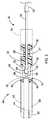
組織T(図11)と係合するための医療機器40を有するある例示的な医療システム20が図1〜4に示されている。医療システム20と機器40は一般に、内視鏡(図示せず)またはその他のスコープの作業チャネルを通じて動作するような大きさおよび構造であるが、システム20と機器40はまた、単独でも、カテーテル、光ファイバ、視覚化システム、ニードル、およびその他等の他の長尺の機器と共に使用されてもよい。一般に、医療システム20は、医療機器40と選択的に接続され、それを動作させるための、長尺のカテーテル24の遠位端23内にスライド可能に格納された駆動ワイヤ22を含む。本明細書でさらに詳しく説明するように、医療機器40は一般に筐体42を含み、これは、組織Tと係合するためにそこに旋回可能に接続された第一のジョー44および第二のジョー46を有する。一般に、ジョー44、46は把持用鉗子を形成するように示されているが、ジョーは、例えば開口を塞いだり止血したりするために組織をクリッピングするのに使用されることが意図される。したがって、ジョーの形状と構造は、様々な形態をとり、多くの目的および機能を果たすことができ、これらはすべて、本発明の教示によることがわかるであろう。 One exemplary
医療システム20において、駆動ワイヤ22はカテーテル24を通ってスライド可能に延びる。「ワイヤ」という用語は駆動ワイヤ22を指すために使用されているが、縦方向の力をある距離(例えば、典型的な内視鏡術、腹腔鏡術、および同様の処置において必要とされる距離)にわたり伝達できるあらゆる長尺の制御部材が使用されてもよいことがわかり、これにはプラスチックのロッドまたはチューブ、シングルフィラメントワイヤ、またはマルチフィラメントワイヤ、金属のロッド、およびその他が含まれる。駆動ワイヤ22はまた、近位端から遠位端に回転/ねじり力を適正に伝達して、医療機器40およびジョー44、46を回転させることができるべきであり、それゆえ、現時点では、駆動ワイヤ22はニチノール(例えば、ニチノールワイヤ)またはその他の超弾性合金で形成される。接続ブロック26は、カテーテル24の遠位端23内にスライド可能に嵌り、そこを通る穴28を画定し、これが駆動ワイヤ22をスライド可能に受ける。接続ブロック26の外部には凹部27が含まれ、2つのピン30(例えば、ステンレススチールワイヤから形成される)がカテーテル24に接続され、凹部27の中に位置付けられて、接続ブロック26の縦方向の移動を限定する。 In the
駆動ワイヤ22の遠位端は遠位ヘッド32を画定し、その大きさは、駆動ワイヤ22より大きく、同様に接続ブロック26内の穴28より大きい。本明細書中で後述するように、遠位ヘッド32は、接続ブロック26をカテーテル24の中でスライドさせ、医療機器40を医療システム20から切り離すために使用される。また、図1〜4においてわかるように、医療機器40の筐体42は内部空間43を画定する管状部材である。筐体42の近位端は、接続ブロック26の遠位端を内部空間43の中に摩擦により受け、それと選択的に接続される。 The distal end of the
筐体42の内部通路43はまた、第一および第二のジョー44、46と、駆動ワイヤ22をジョー44、46に相互接続するために使用されるドライバ48を受ける。図1、2、および5において最もよくわかるように、ドライバ48は近位部分を有し、これは駆動ワイヤ22の大径遠位ヘッド32を受ける大きさのソケット50を画定する。ソケット50の近位側入口において、2つの曲げ可能なロッキングタブ52が形成され、これはドライバ48の残りの部分に関して回転し、ソケット50の大きさを増減させる。ロッキングタブ52は、別に形成されて、ドライバ48に旋回可能に取り付けられてもよく、または、ドライバ48と一体に形成され、ロッキングタブ52を半径方向に内側および半径方向に外側に回転させることができるように曲がる弾性材料で形成されてもよい。ドライバ48の遠位部分はジョー44、46と係合し、それを動作させるためのラック54を画定する。図の実施形態において、ラック54は中央背部56を含み、これは中央背部56から反対に突出し、背のそれぞれの側にある歯58を有する。背部56の片側の歯58の1つの集合は概して第一のジョー44を動作させ、その一方で、背部56の反対側の歯58のもう一方の集合は第二のジョー46を動作させる。ラック54は、歯または、ジョー44、46と接する他の一般的構造の1つの集合を含んでいてもよい。 The
図5において最もよくわかるように、第一および第二のジョー44、46は遠位端60、62を含み、これらは組織を把持し、それと係合するような構造であり、一般にこれらは、2008年12月31日出願の61/141,934において開示されているような鉤爪形状を有しており、その開示の全体を参照により本願に援用する。第一および第二のジョー44、46の近位端64、66は各々、一連の歯を有するピニオンギア68、70を含む。ピニオン68、70の歯はドライバ48のラック54の歯と噛み合い、ドライバ48が縦方向に並進すると第一および第二のジョー44、46が相互に関して回転するように誘導される。一般に、ドライバ48が遠位方向に並進すると、第一および第二のジョー44、46は相互に反対に外側に回転し、その一方で、ドライバ48が近位方向に引込むと、第一および第二のジョー44、46は相互に向かって内側に回転する。ピン80はジョー44、46の近位端の各々に通され、ジョーを筐体42に旋回可能に接続する。旋回接続を形成するためのその他の構造が使用されてもよく、好ましくは、旋回接続はピニオン68、70に関して中央に配置される。 As best seen in FIG. 5, the first and
ジョー44、46が筐体42に旋回可能に取り付けられることに加えて、第一および第二のジョー44、46はまた筐体42にスライド可能にも取り付けられる。(図1〜4と共に)図6および7において最もよくわかるように、筐体42は第一のジョー44のための第一の案内面82と第二のジョー46のための第二の案内面84を画定する。図3においてわかるように、第一および第二の案内面82、84は、筐体42のそれぞれの側に形成された長尺のスロット82a、82b、84a、84bにより形成され、それによって筐体42の厚さが露出し、案内面の役割を果たす。スロット82a、82bは、第一のジョー44の接続ピン80を受けるように整列され、同様に、スロット84a、84bも第二のジョー46の接続ピン80を受けるように整列される。スロットの端、例えば図7に示される遠位端92、94は、筐体42に関するジョー44、46の縦方向の移動を制限する役割を果たす。ジョー44、46の近位端64、66はアパーチャ72、74を含み、これは第一および第二のジョー44、46を筐体42にスライド可能かつ旋回可能に接続するために使用されるピン80(図1、2、および3)を受ける。 In addition to the
図6および7においてわかるように、筐体42は第三の案内面86を画定し、これは筐体42内でのドライバ48の縦方向の移動を案内する。図の実施形態における案内面86は、C字形チャネルとして形成される左側案内面86aと右側案内面86bを含む。図7に示されているように、第三の案内面86はより小さい近位側の幅からより大きい遠位側の幅へと移行し、移行部において肩部88を画定し、これについて図13および14に関してさらに後述する。 As can be seen in FIGS. 6 and 7, the
また図6において示されているように、筐体42の内部通路43は筐体の遠位端を通って延び、それを通じて第一および第二のジョー44、46が延びることができる。それに加えて、図1および2に示されているように、筐体42は第一および第二のジョー44、46が半径方向に外側に回転する時にそこを通過できる大きさである対向するスロット45を画定する。したがって、図1および2から、筐体42が第一および第二のジョー44、46の回転を、これらが完全にまたは部分的に筐体42の内部通路43の中に収容されているときに阻止する役割を果たすことも明白である。筐体を形成するための適当なプラスチックとしては、ポリテトラフルオロエチレン(PTFE)、延伸ポリテトラフルオロエチレン(EPTFE)、ポリエチレンエーテルケトン(PEEK)、ポリ塩化ビニル(PVC)、ポリカーボネート(PC)、ポリアミド、ポリイミド、ポリウレタン、ポリエチレン(高、中、または低密度)が含まれ、適当な金属には、ステンレススチール、ニチノール、および同様の医療用金属および合金が含まれるがこれらに限定されない。 As also shown in FIG. 6, the
次に、医療機器40の動作を、図8〜12を参照しながら説明する。図8に示されているように、第一および第二のジョー44、46は引込み位置にあるように示されており、これらは実質的に筐体42の中に収容されている。用途に応じて、ジョー44、46の遠位端60、62は、それらの引込み位置において筐体42の遠位端からわずかに突出していてもよく、またはこれらは筐体42の中に完全に位置付けられていてもよい。駆動ワイヤ22が遠位方向に(図8のページの右側に)並進移動すると、遠位ヘッド32がドライバ48と係合し、ドライバ48とジョー44、46が筐体42を通って遠位方向にスライドする。ドライバ48とジョー44、46は縦方向にスライドし、その後、回転するが(ただし、ドライバ48のラック54はジョー44、46の近位端64、60においてピニオン68、70と噛み合う)、これは、縦方向の移動に対する抵抗がジョー44、46を回転させるのに必要な力より小さい(あるいは、筐体42がジョー44、46の回転を、これらが筐体42の中にある時に阻止することができる)からである。前述のように、この縦方向の移動は、第一および第二の案内面82、84により案内され、これらは、ジョー44、46を筐体42にスライド可能かつ旋回可能に接続するピン80を受ける。 Next, the operation of the
図9に示されているように、第一および第二のジョー44、46は伸展位置を有し、このとき、ジョーは実質的に筐体42の遠位端から突出し、その近位端64、66は筐体42の遠位端に隣接して位置付けられる。したがって、駆動ワイヤ22および、したがってドライバ48をさらに遠位方向に前進させると、ピニオン68がラック54の歯58の上方で回転することがわかるであろう。図10において最もよくわかるように、第一および第二のジョー44、46は相互に半径方向に外側に回転して、組織を受ける位置に至る。特に、筐体42の遠位端にスロット45が存在するために、ジョー44、46は丸90°にわたり回転でき、それゆえ、それらの間に少なくとも180°をなす。スロット45の大きさとラック54およびピニオン68、70の構成を通じて、第一および第二のジョー44、46は相互にさらに離れるように回転できることがわかるであろう。 As shown in FIG. 9, the first and
図10に示される組織を受ける位置において、医療機器40とそのジョー44、46は、組織Tに隣接して位置付けられる。図11に示されているように、組織Tは第一および第二のジョー44、46間に位置付けられてもよく、ジョー44、46は図9に示されるそれらの位置に向かって回転して戻る。組織Tは1層として示されているが、複数の層がジョー44、46間に挟まれてもよい。一般に、駆動ワイヤ22とドライバ48が近位方向に引込むと、再び第一および第二のジョー44、46が回転してそれらの間の組織Tを把持する。図12に示されるように、駆動ワイヤ22とドライバ48がさらに近位方向に引込むと、ジョー44、46は近位方向に(図12のページの左側に)縦方向に移動する。 In the position for receiving the tissue shown in FIG. 10, the
医療機器40がクリップとしての役割を果たし、組織Tを把持したままであるようにするため、または2層の組織を相互に関してクリッピングした状態に保持するために、ジョー44、46はその位置にロックされてもよく、医療システム20の駆動ワイヤ22は医療機器40から切り離される。図13に示されるように、第三の案内面86(これはドライバ48を案内する)は近位部分86pと遠位部分86dを含む。第三の案内面86の近位部分86pの幅(図13のページの上下に測定)は第三の案内面86の遠位部分86dの幅より大きい。前述のように、第三の案内面86は筐体42の対向する面またはC字形のチャネル86a、86bによって形成される。近位部分86pと遠位部分86dとの間の移行は肩部88、すなわち筐体42のそれぞれの側の2つの肩部88a、88bを画定する。肩部88a、88bは、ドライバ48上に配置されたロッキングタブ52と係合するような大きさであり、そのように位置付けられる。 The
図13に示されているように、ドライバ48が第三の案内面86の遠位部分86dの中に配置されているとき、ロッキングタブ52は半径方向に内側に付勢されて、駆動ワイヤ22としっかりと摩擦係合する。言い換えれば、ドライバ48により形成される、遠位ヘッド32を受けるためのソケット50は入口を有し、これはロッキングタブ52が内側に曲がることにより狭くなる。好ましくは、ロッキングタブ52は弾性変形というより塑性変形し、タブ52は機器の初期組立中に遠位ヘッド32の周囲で内側に曲がってもよく、それゆえ、第三の案内面86の遠位部分86dに合わせた大きさであってもよい。図13に示されるこの状態で、駆動ワイヤ22はドライバ48と、したがって第一および第二のジョー44、46としっかりと係合する。 As shown in FIG. 13, when the
駆動ワイヤ22とドライバ48が、例えば図12に示されるように組織を把持したところで近位方向に引込むと、ドライバ48の近位端は、ロッキングタブ52が半径方向に外側に移動できるようにするために、より大きい幅を有する第三の案内面86の近位部分86p内に受けられる。したがって、図14に示される状態において、ロッキングタブ52は駆動ワイヤ22の遠位ヘッド32にゆるく、取り外し可能に接続されてもよい。すなわち、ジョー44、46の近位方向への引込みは、筐体42の遠位端に係合する組織Tによって限定されるか、またはピン80が、第一および第二の案内面82、84を画定するスロット82a、82b、84a、84bの近位端と当接する。したがって、ジョー44、46およびドライバ48の近位方向への移動がこのように限定されると、駆動ワイヤ22とその遠位ヘッド32の近位方向への移動は、遠位ヘッド32をドライバ48のソケット50から引き抜くために利用されてもよい。この動作はまた、ロッキングタブ52を半径方向に外側にさらに曲げるためにも使用されてよい。駆動ワイヤ22上に適切な量の遠位方向への力が加わることによって、遠位ヘッド32はロッキングタブ52を通じて近位方向に移動し、これらを半径方向に外側に塑性変形させる。組織Tの自然の弾性によってジョー44、46が筐体からその伸展位置へと引き出される傾向がある場合、ロッキングタブ52、54は筐体42の第三の案内面の肩部88a、88bと当接して、ジョー44、46がさらに遠位方向に移動するのを阻止する。 When the
次に、図15および16を参照すると、駆動ワイヤ22と遠位ヘッド32が近位方向にさらに引き戻されると、拡張遠位ヘッド32は、カテーテル24の遠位端23内にスライド可能に嵌る接続ブロック26と当接する。駆動ワイヤ22にかかる十分な量の近位方向の力は、接続ブロック26と筐体42の近位端との間の摩擦結合を克服し、それゆえ、接続ブロック26を近位方向に(図15および16のページの右に)移動させ、図16に示されるように、接続ブロック26を管状コネクタ24内に引込める。カテーテル24は、駆動ワイヤ22と接続ブロック26を近位方向に引込める間に筐体42に対向力を提供するために使用できる。したがって、駆動ワイヤ22、カテーテル24、および接続ブロック26は、医療機器40から完全に切り離されてもよく、それによって第一および第二のジョー44、46と筐体42は、組織Tがジョー44、46間に挟まれた状態のまま、生体内に保持される。接続ブロック26は、ピン30を介してカテーテル24の遠位端24に保持され、ピンは凹部27内に位置付けられ、接続ブロック26の近位および遠位端と係合して、その縦方向の移動を制限する。 15 and 16, when the
長尺のカテーテル24(または他の長尺管状部材、例えばシース、管、スコープ、またはその他)は駆動ワイヤ22をスライド可能に収容し、それに沿って近位方向にシステム20の近位端まで延び、その長さは、体内のあらゆる所望の位置に機器40を設置し、駆動ワイヤ22とカテーテル24の近位端が体外に位置付けられて、医療専門家により使用されるのに適している。駆動ワイヤ22とカテーテル24の相対的並進を制御するための制御ハンドル(図示せず)は当業界でよく知られており、システム20の近位端で採用されてもよい。 An elongate catheter 24 (or other elongate tubular member, such as a sheath, tube, scope, or the like) slidably receives the
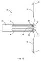
他の実施形態と把持ジョー44、46の形成方法が図17〜18に示されている。前の実施形態のジョーは一般に機械加工されるが、ジョー44、46はまた、スタンピング加工によって形成されてもよい。好ましくは医療用ステンレススチールの金属の平坦小片が、図17に示される形状144へとスタンピング加工される。この形状は、わずかに狭い遠位端160を含み、これは次に、組織を把持し、それと係合するために、図18に示される形状へと曲げることができる。遠位端160はまた、ぎざぎざの縁辺または、用途に応じてその他の形状もしくは縁辺特徴を含むようにスタンピング加工されてもよい。近位端164は一般に、2つのアーム166を含み、これは歯車168へと続く。図18に示されるように、歯車168が把持され、約90度回転されて、歯車168はシート144の平面に垂直な平面内に延びることになる。歯車168はまた、案内ピンを受けるための貫通穴172も含む。また、この実施形態におけるジョー44、46は1つのアーム166と1つの歯車168で形成されてよいこともわかるであろう。 Other embodiments and methods of forming the gripping
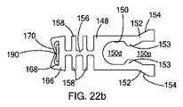
ドライバ148と駆動ワイヤ122の他の実施形態が図19〜22に示されている。ドライバ148は一般に、2つのロッキングタブ152により形成されるソケット150を含む。この実施形態において、ロッキングタブの近位部分は傾斜した肩部154を画定し、これは前述のように筐体42の中の第三の案内面86と係合するために、横方向に外側に傾斜する。ロッキングタブ152はまた、内側突起153も含み、これは横方向に内側に突出して、ソケット150を遠位部分150dと近位部分150pに分割する。ドライバ148は同じく、中央背部156および反対向きの歯158を含む。この実施形態において、ドライバ148の遠位端166は、内側に突出する2つのフランジ170により画定されるポケット168を含み、これについては本明細書中でさらに説明する。2つのフランジ170は、ポケット168の遠位側に沿って延び、それらの間にポケット168に到達するためのギャップが残される。 Other embodiments of
図20および21からわかるように、駆動ワイヤ122のこの実施形態は遠位ヘッド132を含み、これは駆動ワイヤ122の遠位端を曲げることによって図のような半円形、好ましくは180度〜360度の弧を描くように形成される。したがって、遠位ヘッド132は、ロッキングタブ152の内側突起153を受ける大きさの開口133を画定する。図のように、ソケット150の遠位部分150dは湾曲した遠位ヘッド132の最も遠位側部分を受け、その一方で遠位ヘッド132の近位部分はソケット150の近位部分150pを通り、そこから離れて近位側に突出する。前述のように、ロッキングタブ152はここで、塑性変形するように構成され、それゆえ、図19に示されるように成型され、駆動ワイヤ122に接続された後、タブ152は半径方向に内側に曲げられて、突起153をソケット132の開口133の中に固定する。この状態で、ロッキングタブ152の外側肩部154は第三の案内面86の中に、より詳しくは第三の案内面86の遠位部分86dの中に、さらに変形せずに嵌る大きさである。 As can be seen from FIGS. 20 and 21, this embodiment of the
図22aおよび22bに示されるように、他の実施形態の医療機器140は、ちょうど前の実施形態のように筐体142と、把持アーム144、146と、を含んでいてもよいが、この実施形態においては、代替的なドライバ148と、追加の付勢要素、すなわち付勢ストリップ190と、を含む。図22bにおいて最もよくわかるように、ドライバ148の遠位端166はポケット168の中に付勢ストリップ190を受ける。フランジ170は、図のように内側および近位側に曲げられ、金属ストリップ190としっかり係合し、それをドライバ148に固定する。付勢ストリップ190は好ましくは、弾性材料のシートから形成される薄いストリップ、より好ましくは、例えばステンレススチール、ニチノール、または他の生体適合超弾性合金で形成された金属ストリップである。したがって、ドライバ148が近位方向に移動されてジョー144、146が閉じると、付勢ストリップ190は図22aにおいて点線で示されるように、V字形またはU字形へと付勢されることがわかるであろう。すなわち、付勢ストリップ190はその自然の、付勢されていない状態ではまっすぐの形状を有し、V字形に曲げられると、ジョー144、146に半径方向に外側の力をかける。この付勢力によってジョー144、146は開閉位置間でスムーズに回転し、移行する。また、付勢ストリップ190はまた、その当初の、付勢されていない、V字形またはU字形として形成された位置を有し、ジョー144、146に固定されて、それが半径方向に内側の付勢力を加えるようにすることもできることがわかるであろう。金属ストリップ190の自由端192は単にジョー44、46を圧迫するだけで、それにしっかりと、または堅く取り付けられることはない。 As shown in FIGS. 22a and 22b, another embodiment of the
次に図23を参照すると、他の実施形態の医療機器240が示されており、同じく筐体242と、それにスライド可能に取り付けられた対向するジョー244、246と、を含む。筐体242は同じく、ジョー244、246の移動を案内するための第一および第二のガイド282、284を含む。しかしながら、この実施形態においては、各ジョー244、246がそれぞれ付勢ストリップ290a、290bを含む。ストリップ290a、290bの遠位端291はジョー244、246の外部に、好ましくはそれらの遠位端に、好ましくは接着剤、はんだ、溶接、またはその他の既知の結合方法によりしっかりと取り付けられる。図24および25において最もよくわかるように、筐体240は筐体240のそれぞれの側にある2つの外部通路294を含み(図24および25に一方が示されている)、これらは弾性ストリップ290a、290bを、それらが閉鎖/引込み位置にあるときに筐体の外面と平らな状態になるように受ける大きさである。ストリップ290a、290bの近位端293は、基部295と横木296により形成されるT字形状を含む。基部295は、筐体240に形成された、より小さいスロット296を通って延びる。スロット296はチャネル294と同一の広がりを持つ。横木296は筐体240の内面に乗り、ストリップ290と筐体240との間のスライド可能な接続を保持する。したがって、ストリップ290a、290bの近位端293は、チャネル294とそのスロット296を介して、スライド可能かつ旋回可能に筐体240に取り付けられ、ストリップ290a、290bが把持ジョー44、46と共に、図24および25に示されるそれらの開閉位置間で移動できることがわかるであろう。 Referring now to FIG. 23, another embodiment of a
次に、図26〜30を参照すると、他の実施形態のドライバ348が示されている。図26および27において最もよくわかるように、ドライバ348は同じくソケット350を含み、これは2つのロッキングタブ352によって形成され、それらは内側突起353と外側肩部354を有し、ソケット350を遠位部分350dと近位部分350pとに分割する。前の実施形態のドライバと異なり、この実施形態においては、遠位部分がZ字形の歯車ラックを画定する。概して、中央板356が前の実施形態の中央背部56、156に代わり、板356は、筐体342の縦方向の平面に平行な平面内に延びる(図29)。中央板356の平面はまた、ドライバ348の近位側の半分(すなわち、ソケット350とタブ352を含むほう)に対して垂直でもある。第一の集合の歯358aは中央板356から反対に横方向に、第一の方向へと突出し、第二の集合の歯358bは中央板356から反対に横方向に、第二の方向へと突出する。第一および第二の集合の歯358a、358bは中央板356の両端から延び、第一および第二の方向は概して相互に反対である。歯の集合358a、358bは各々、歯358a、358bの周辺に延びる2つの外側フレーム360によって中央板356にしっかりと保持される。 Referring now to FIGS. 26-30, another
したがって、図28において最もよくわかるように、医療機器340は、第一および第二の把持ジョー344、346を含み、その各々が近位端366と、ジョー344の本体から直角に突出するように曲げられている歯車の歯368を有する。したがって、第一の集合の歯358aは第二のジョー346の歯車368を受け、その一方で、第二の集合の歯358bは第一のジョー344の歯車368を受ける。特に、ジョー344、346の近位端366を図のように横方向/直角に曲げることにより、1つのピン380が歯車368を通過することができ、それゆえ、両方のジョー344、346により共有される。またさらに、図29に示されているように、筐体342はそれゆえ、1つのみの案内面382を含んでいてもよく、これは筐体342の各側面の、1つのピン380の端を受ける1つのスロットにより形成される。第一および第二のジョー344、346はそれによって1つの案内面382(ジョー案内面)と案内スロットを共有し、それゆえ、それらの調和された、スムーズな開閉が確保されることが分かる。 Thus, as best seen in FIG. 28, the
図29に示されているように、スロット357が中央板356に形成され、ピン380およびジョー案内面382と整列して、ドライバ348がジョー344、346に関して前方に移動するとピン380を受ける。前述し、図30に示すように、ピン380(ジョー344、346の近位端366および歯車368により共有される)が1つのジョー案内面382の遠位端に当たると、ドライバ348は引き続き遠位方向に移動して歯車368がドライバ348のラック/歯358a、358bを介して回転し、それによってジョー344、346の回転が誘発される。 As shown in FIG. 29, a
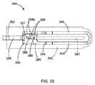
次に、図31〜33を参照すると、他の実施形態の医療システム420と医療機器440が示されている。この実施形態において、医療システム420は同じく、駆動ワイヤ422を含み、これは駆動ワイヤ422の遠位端を図のような形状に曲げることにより形成される遠位ヘッド432を有する。医療システム420はまた、カテーテルアタッチメント430を含み、これは概して管状の部材であり、カテーテル24の近位端に接続されて、接続ブロック426をスライド可能に受けるために使用される。カテーテルアタッチメント430は、制御ワイヤ422および接続ブロック426にアクセスする1対の開口434を含み、接続ブロック426を引込みまたは伸展位置の何れかに保持するために工具が使用されてもよく、これについては、本願と同時に出願された米国特許出願第61/391,878号明細書および本願と同時に出願された特許出願第61/391,875号明細書にさらに詳しく記載されており、その開示の全体を参照によって本願に援用する。 31-33, another embodiment of a
医療機器440は、筐体442を含み、これはカテーテル24およびそのカテーテルアタッチメント430に接続ブロック426を介して取り外し可能に接続される。筐体442は、ドライバ448を介して駆動ワイヤ422に接続される1対のジョー444をスライド可能に受ける。前の実施形態と同様に、ドライバ448は、駆動ワイヤ422の遠位ヘッド432と釈放可能に係合するロッキングタブ452によって画定されるソケット450を含む。ドライバ448の遠位部分は複数の歯458を含み、これは前述のように、ジョー444の回転を駆動する役割を果たす歯車またはラックを画定する。ドライバ448の遠位端466は、付勢ストリップ490としっかりと係合するために使用されるフランジによって画定されるポケットを含む。筐体442はさらに、1対の案内面またはスロット482を画定し、これはジョー444の縦方向および回転移動を案内する。 The
この実施形態において、ジョー444と筐体442は、完全に引込められた位置(図に示される)において、ジョー444が筐体442の端から遠位方向に(少なくとも部分的に)突出するように構成される。図32において最もよくわかるように、遠位ヘッド432がロッキングタブ452の中に押し込まれると、これらは外側に塑性変形して、筐体内の肩部446と係合し、ジョー444は完全に引込められる。このようにして、筐体442の長さを短縮でき、その中のジョー444を案内するための案内スロット482も同様である。また、図32においてわかるように、ジョー444の遠位端はぎざぎざ445または、組織の把持に役立つその他の構造を含む。 In this embodiment, the
この実施形態においては、前述のすべての実施形態と同様に、駆動ワイヤ422が、回転力とトルク(例えば、システム20/420の近位側動作端から)を、遠位ヘッド432およびドライバ448を通じてジョー444に伝達できることにも留意されたい。そのため、医療機器440は、駆動ワイヤ422の回転を介して回転されてもよく、すなわち、ジョー444、ジョーピン(例えば80)、筐体442、およびドライバ448はすべて、1つのユニットとしてカテーテル24に関して回転する。筐体442がまた、接続ブロック426に回転不能に接続されるかぎり(例えば、それらの間の摩擦による)、カテーテルアタッチメント430が使用されていないとき、接続ブロック426もまたカテーテルアタッチメント430(またはカテーテル、例えば24)の中で回転してもよい。したがって、ジョー444の向きは、駆動ワイヤ422の近位端の回転を通じて回転されて、ジョーを把持またはクリッピング対象の組織または物質に関して向き付けることができる。駆動ワイヤ422を中実のニチノールワイヤから形成することにより、医療機器440の回転のための良好なトルク伝達ができることが判明した。 In this embodiment, as with all previous embodiments, the
また、ジョー444を、それらが完全に引込んだ位置で少なくとも部分的に筐体442から突出するようにすると、ジョー444の向きが見えるようになり、それらを組織の周囲で開閉する前にジョー444を回転させやすくなることも判明した。またさらに、組織が筐体442の遠位端と当接する前に、ジョー444の中にさらに多くの組織が収容されてもよい。ジョー444が筐体442から突出する距離は、特定の用途に応じて異なっていてもよく、すなわち、ジョー444の遠位端と筐体442の遠位端との間に十分な空間が確保されるように形成される、組織の厚さまたは手順の種類に対応するような大きさである。 Also, if the
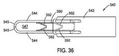
図34〜36を参照すると、他の実施形態の医療機器540が示されている。この実施形態において、医療機器540は同じく、前述の実施形態の何れの医療システムの残りの部分のほか、前述の実施形態と同様に、筐体542およびジョー544のペアを含む。医療システムおよび機器の前述の実施形態またはその特徴はすべて、この医療機器540にも使用されてよい。この実施形態において、ドライバ548は同じく、遠位端566を含み、これは付勢ストリップ590としっかりと係合するために使用されるポケットとフランジを画定する。付勢ストリップ590は半径方向に外側に付勢され、それらの外側に向かう回転の、すべてではないにしても、ほとんどを通じてジョー544と係合する。この実施形態において、付勢ストリップ590は少なくとも1つの、好ましくは複数のプロング592を提供するようにスタンピング加工され、図の実施形態では4つのプロング592が示されている。プロング592は好ましくは、スタンピング、切削、またはその他の材料加工によってストリップ590から直接形成されるが、プロング592は別に形成されたストリップ590に取り付けられてもよい。プロングは好ましくは自由端を有し、これは医療機器540を介した組織の係合を容易にするように鋭利である。 34-36, another embodiment of a
図35に示されるように、医療機器540が開位置にあるとき、プロング592は半径方向に内側に延び、縦軸L.A.に概して直交する。図36に示されるように、医療機器540が閉位置にあるとき、プロング592は範囲方向に内側に、近位方向に好ましくは15°〜90°、より好ましくは約15°〜45°の角度(それぞれのストリップ部分の軸に関して)で突出する。図36において最もよくわかるように、プロング592は好ましくは、対向するペア間に、2つのプロング592が相互に向かって突出して、それらの間に小さい横方向の空間が画定されるように配置される。あるいは、プロング592の自由端はそれぞれの対向するプロング592の自由端と接触してもよい。さらにまた、図36Aに示される他の変形型においては、ストリップ590aが対向するストリップ部分に、互い違いの(閉位置では縦方向に離間される)プロング592aを有していてもよく、その長さは、閉位置において、プロング592aの自由端が対向するストリップ部分の第一の部分と接触する長さであり、組織Tのためのジグザグの蛇行路を提供する。上述のプロングの変形型の何れの組合せを併用してもよい。 As shown in FIG. 35, when the
ジョー544が、鉤爪形状を形成する遠位端545を形成するかぎり、ジョー544はそれらの間に把持空間547を画定する。ジョー544の遠位端545が相互に直接係合する間に、ジョー544間の横方向の距離(すなわち、把持空間547の横方向の幅)より薄い組織は部分的にしか拘束されない。したがって、プロング592は把持空間547の中に延び、把持空間547の領域内でジョー544間の横方向の距離を有効に短縮させ、ジョー544間に位置付けられた組織と直接係合する。付勢ストリップ590とそのプロング592は、医療システムと機器の前述の実施形態の何れに組み込まれてもよい。 As long as the
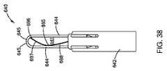
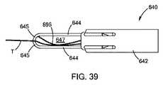
次に、図37〜39を参照すると、他の実施形態の医療機器640が示されている。医療システムおよび機器の前述の実施形態またはその特徴はすべて、この医療機器640に使用されてよい。この実施形態において、医療機器は同じく筐体642を含み、これはドライバ648による運動を通じて駆動される1対のジョー644をスライド可能かつ回転可能に受ける。ジョー644間で組織と係合しやすくするために、把持ストリップ695がジョー644の一方に提供され、これを本明細書の中で第一のジョーと呼んでもよい。把持ストリップ695は薄い平らなストリップであり、好ましくは生体適合金属またはプラチック、例えばステンレススチールまたはニチノールから形成され、その幅はジョー644の幅と等しいか、それより小さい。 37-39, another embodiment of a
把持ストリップ695は遠位部分697と近位部分698を有する。遠位部分697は好ましくは、遠位端を含み、これは例えば溶接部696によって第一のジョー644の遠位端に直接および/またはしっかりと取り付けられる。溶接部696が示されているが、把持ストリップ695の遠位部分697は第一のジョー644の遠位端645に、他の何れの既知の手段、例えば接着剤、各種の溶接もしくははんだ法、またはその他の機械的接続または固定具で取り付けられてもよい。前述のように、ジョー644は湾曲した鉤爪形状を有する遠位端645を含み、好ましくは、湾曲遠位端645の近位部分に、または第一のジョー644の湾曲遠位端645に直に近接して溶接部696が形成される。要するに、把持ストリップ695の遠位端はジョー644の遠位部分に取り付けられる。 The
把持ストリップ695の近位部分698は近位端を含み、これは浮動型であるが、好ましくは、第一のジョー644の近位端とゆるく係合するような大きさと構造である。図37および38において最もよくわかるように、把持ストリップ695は凹型(第一のジョー644と対向する)に曲げられ、それによって遠位部分697は半径方向に内側に縦軸に向かって、好ましくは軸を越えて反対のジョー644に向かって突出し(閉位置)、その一方で、把持ストリップ695の近位部分698は、後方に、第一のジョー644(すなわち、それが取り付けられているジョー)に向かって突出する。把持ストリップ695の近位部分698と近位端はドライバ648と縦軸の半径方向に外側に位置付けられる。把持ストリップ695の近位端は、希望に応じて第一のジョー644に取り付けられてもよい。 The
図38において最もよくわかるように、医療機器640の閉位置において、把持ストリップ695の遠位部分697はジョー644間に画定される把持空間647全体にわたり突出し、対向する(または第二の)ジョー644と係合する。すると、把持ストリップ695の近位部分698は、図39において最もよくわかるように、第一のジョー644に向かって後方に突出する。医療機器640の閉位置において、組織Tがジョー644間と把持空間647内に位置付けられているときに、把持ストリップ695は組織Tを対向するジョー644にしっかりと押し付ける役割を果たし、その一方で、ジョー644の遠位端645はそれらの間で組織Tとしっかりと係合する。このようにして、医療機器640は、組織Tとの把持において改善される。 As best seen in FIG. 38, in the closed position of the
次に、図40を参照すると、また別の実施形態の医療機器740が示されている。医療システムおよび機器の前述の実施形態またはその特徴はすべて、この医療機器740に使用されてもよい。この実施形態は図37〜39の実施形態と実質的に同じであり、筐体742を含み、これはドライバ766により駆動される1対のジョー744をスライド可能かつ回転可能に受ける。上述の把持ストリップ695と同様の形状を有する把持ストリップ795は、その遠位端において、溶接部796を介して第一のジョー744の遠位部分に取り付けられる。この実施形態において、把持ストリップ795には複数のプロング792が設けられ、図40には4つのプロングが示されている。プロング792は図34〜36の実施形態において示され、説明されているプロング592と同様であり、同様の形状を有し、それと同様に形成されてもよい。簡単に言えば、プロング792は好ましくは、把持ストリップ795から直接スタンピング加工され、三角形であり、ジョー744間の組織と、好ましくは僅かに穿刺することによって係合するように鋭利な末端を有する。 Referring now to FIG. 40, another embodiment of a
次に、図41および42を参照すると、他の実施形態による医療840が示され、説明される。この実施形態において、医療システムおよび機器の前述の実施形態またはその特徴がすべて、医療機器840に使用されてもよい。特に、この実施形態は、把持ストリップ895が付勢ストリップ890と共にどのように採用されてもよいかを示す。付勢ストリップ890は、ストリップ190、490等の前述の付勢ストリップの何れとも実質的に同じであり、ドライバ848の遠位端にしっかりと取り付けられる。同様に、把持ストリップ895は、図37〜40に示される把持ストリップ695,795と実質的に同様であり、第一のジョー844の遠位端部分に取り付けられた遠位端を含む。把持ストリップ895の、付勢ストリップ890と重複する部分は、付勢ストリップ890の半径方向に外側に位置付けられる。したがって、付勢ストリップ890は把持ストリップ895と直接係合し、それ自体は、第一のジョー844にしっかりと取り付けられて、半径方向に外側に付勢する力を付勢ストリップ890から第一のジョー844(把持ストリップ895を有する)に伝達する。図42に示される、医療機器840の閉位置において、把持ストリップ895は好ましくは、付勢ストリップ890より剛性が高く、それによってそれが引き続き反対のジョーに向かって延び、それと係合した後に、対向するジョーから反対に横方向に湾曲し、それによって組織と付勢ストリップ890の両方を対向するジョー844に押し付ける。 41 and 42, a medical 840 according to another embodiment is shown and described. In this embodiment, all of the foregoing embodiments of the medical system and device or features thereof may be used for the
把持ストリップ895は、図41〜42の実施形態において、付勢ストリップ890の半径方向に外側に位置付けられるように示されているが、把持ストリップ895の近位端は浮動型であるため、これは付勢ストリップの対応する部分の半径方向に内側に位置付けることもできる。例えば、図43の医療機器940aの実施形態に示されているように、医療機器940aは、対向するジョー944aをスライド可能かつ回転可能に受ける筐体942を含む。ここで、把持ストリップ995aは、上述の把持ストリップと実質的に同じであり、その近位部分と近位端において、図43に示されるように、付勢ストリップ990aの半径方向に内側に位置付けられる。好ましくは、把持ストリップ995aの近位端は、付勢ストリップ990aおよびドライバ948aとの接合部に配置される。ここでもまた、ドライバ948aは、付勢ストリップ990aにしっかりと取り付けられた遠位端966aを含む。同様に、この実施形態において、第二の把持ストリップ995aが対向するジョー944aに取り付けられ、前述の実施形態と同様に構成され、ジョー944aに取り付けられているように示されている。したがって、付勢ストリップ990aはジョー944aと直接係合し、それを外側に付勢してもよく、その一方で、把持ストリップ995aはジョー944aの遠位端に取り付けられるが、ジョー944a間の把持空間を実質的に埋めるような大きさと構造である。 The
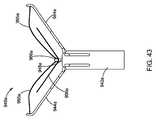
第二の把持ストリップを追加するための同様の変形型が他の実施形態の医療機器940bと図44において示されている。図43の実施形態と同様に、医療機器940bは筐体942bを含み、これはドライバ948bにより駆動される1対の対向するジョー944bをスライド可能かつ回転可能に受ける。ここでもまた、ドライバ948aは遠位端966bを含み、これは付勢ストリップ990bにしっかりと取り付けられる。この実施形態において、2つの把持ストリップ995bが同じく提供されているが、把持ストリップ995bは付勢ストリップ990bの半径方向に外側に位置付けられる。したがって、付勢ストリップ990bは、対向するジョー944bに直接取り付けられている対向する把持ストリップ995bに押し付けられ、それによってジョーが半径方向に外側に付勢される。同時に、把持ストリップ995bはジョー944b間の把持空間を実質的に埋め、ジョー944bのより長い長さにわたって組織としっかりと係合する。医療システムおよび機器の前の実施形態またはその特徴はすべて、医療機器940aおよび940bに使用されてもよい。 A similar variation for adding a second gripping strip is shown in another embodiment of the
本発明の各種の実施形態の上の説明文は、例示と説明を目的として提示されている。これがすべてではなく、開示された正確な実施形態に発明を限定することは意図されていない。上述の教示を参照すれば、多数の改良または変形が可能である。前述の実施形態は、本発明の原理とその実践的応用を最もよく例示し、それによって当業者が各種の実施形態で、企図される特定の用途に適した様々な改良を加えて本発明を利用できるようにするために選択され、説明された。このような改良と変更はすべて、付属の特許請求の範囲により決定される本発明の範囲を公正に、合法的に、公平に付与される広さに従って解釈した場合に、その中に包含される。 The above description of various embodiments of the present invention is presented for purposes of illustration and description. It is not intended to be exhaustive or to limit the invention to the precise embodiments disclosed. Many modifications or variations are possible in view of the above teachings. The foregoing embodiments best illustrate the principles of the invention and its practical application, thereby enabling those skilled in the art to make various modifications in various embodiments, with various modifications suitable for the particular application contemplated. Selected and explained to be available. All such modifications and changes are encompassed therein when the scope of the present invention, as determined by the appended claims, is construed in a fair, lawful and impartial manner. .
Claims (9)
Translated fromJapanese筐体であって、内部通路と、前記筐体の近位および遠位端間に延びる縦軸と、を画定する筐体と、
前記筐体に関して回転可能な第一のジョーであって、近位および遠位端を有する第一のジョーと、
前記筐体に関して回転可能な第二のジョーであって、近位および遠位端を有する第二のジョーと、
前記第一および第二のジョーの近位端と係合するドライバであって、前記筐体の前記縦軸の方向で変位することにより前記第一および第二のジョーを前記筐体に関して回転し、前記第一および第二のジョーをそれらの前記遠位端が相互に離れた組織受入れ位置と、前記遠位端が相互に近づいた組織把持位置との間で変位させるドライバと、
前記第一および第二のジョー間に位置付けられて前記第一および第二のジョーをそれらの前記遠位端が相互に離れる方向又は近づく方向に付勢する付勢ストリップであって、前記第一および第二のジョーが前記組織把持位置となったときに折り曲げられて、折り曲げ部、前記折り曲げ部から前記第一のジョーに沿って前記第一のジョーの前記遠位端の方向に延びる第一の部分および前記折り曲げ部から前記第二のジョーに沿って前記第二のジョーの前記遠位端の方向に延びる第二の部分を有するようになされており、前記第一および第二の部分の少なくとも一方が該少なくとも一方から15°〜45°の角度の角度で折り曲げられて前記第一および第二のジョーの他方に向けて且つ先端が前記折り曲げ部の方向に向かうようにされた少なくとも1つの突起を含む付勢ストリップと、
前記ドライバに選択的に接続されて、それとともに縦方向に移動する長尺の駆動ワイヤと、
を含む医療機器。In a medical device for engaging tissue, a medical system is
A housing defining an internal passage and a longitudinal axis extending between the proximal and distal ends of the housing;
A first jaw rotatable with respect to the housing, the first jaw having proximal and distal ends;
A second jaw rotatable with respect to the housing, the second jaw having proximal and distal ends;
A driver that engages the proximal endsof the first and second jaws, rotating the first and second jaws relative to the housing by displacing in the direction of the longitudinal axis of the housing; A driverfor displacing the first and second jaws between a tissue receiving position with their distal ends spaced apart from each other and a tissue grasping position with the distal ends approaching each other ;
Abiasing strip positioned betweenthe first and second jaws for biasing the first and second jaws in a direction in which their distal ends move away from or approach each other; And the second jaw is folded when the tissue gripping position is reached, and a first bent portion extends from the bent portion along the first jaw toward the distal end of the first jaw. And a second portion extending from the fold along the second jaw in the direction of the distal end of the second jaw, of the first and second portions At least one of the first and second jaws is bent at an angle of 15 ° to 45 ° from at least one of the first and second jaws, and at least a tip is directed to the bent portion. A biasing stripincluding one protrusion ;
A long drive wire selectively connected to the driver and moving longitudinally therewith;
Including medical equipment.
The medical device of claim 1,wherein the fold of the biasing strip is secured to and moves with the distal end of the driver.
Applications Claiming Priority (3)
| Application Number | Priority Date | Filing Date | Title |
|---|---|---|---|
| US14/484,824 | 2014-09-12 | ||
| US14/484,824US10010336B2 (en) | 2009-12-22 | 2014-09-12 | Medical devices with detachable pivotable jaws |
| PCT/US2015/049614WO2016040760A1 (en) | 2014-09-12 | 2015-09-11 | Medical devices with detachable pivotable jaws |
Publications (2)
| Publication Number | Publication Date |
|---|---|
| JP2017526480A JP2017526480A (en) | 2017-09-14 |
| JP6415704B2true JP6415704B2 (en) | 2018-10-31 |
Family
ID=54150741
Family Applications (1)
| Application Number | Title | Priority Date | Filing Date |
|---|---|---|---|
| JP2017514331AActiveJP6415704B2 (en) | 2014-09-12 | 2015-09-11 | Medical device with removable swivel jaws |
Country Status (5)
| Country | Link |
|---|---|
| EP (2) | EP3190992A1 (en) |
| JP (1) | JP6415704B2 (en) |
| CN (1) | CN106999200B (en) |
| AU (1) | AU2015314906B2 (en) |
| WO (1) | WO2016040760A1 (en) |
Families Citing this family (4)
| Publication number | Priority date | Publication date | Assignee | Title |
|---|---|---|---|---|
| CN109350143B (en)* | 2018-11-28 | 2023-11-03 | 大连医雅科技有限公司 | Medical laparoscope clamping device and method |
| CN111870431A (en)* | 2020-08-20 | 2020-11-03 | 宁波市医疗中心李惠利医院 | Detachable otology surgical instrument |
| CN112155669A (en)* | 2020-10-12 | 2021-01-01 | 常州安康医疗器械有限公司 | Liquid guiding type ultrasonic knife head |
| CN117462305B (en)* | 2023-12-28 | 2024-04-05 | 苏州汇禾医疗科技有限公司 | Valve clamp conveying system and valve clamp system |
Family Cites Families (15)
| Publication number | Priority date | Publication date | Assignee | Title |
|---|---|---|---|---|
| US3581745A (en)* | 1968-10-23 | 1971-06-01 | William C Eller | Instrument for removing obstructions from the throat |
| US4955897A (en)* | 1988-08-22 | 1990-09-11 | Ship Arthur G | Tissue forceps |
| US5009657A (en)* | 1989-12-14 | 1991-04-23 | Mohammed S. Jahanger | Umbilical cord cutting and clamping device |
| US5542432A (en)* | 1992-02-18 | 1996-08-06 | Symbiosis Corporation | Endoscopic multiple sample bioptome |
| US5584855A (en)* | 1995-04-27 | 1996-12-17 | Onik; Gary M. | Safety surgical grasping forceps |
| US8216256B2 (en)* | 1999-04-09 | 2012-07-10 | Evalve, Inc. | Detachment mechanism for implantable fixation devices |
| US7226467B2 (en)* | 1999-04-09 | 2007-06-05 | Evalve, Inc. | Fixation device delivery catheter, systems and methods of use |
| US20020138086A1 (en)* | 2000-12-06 | 2002-09-26 | Robert Sixto | Surgical clips particularly useful in the endoluminal treatment of gastroesophageal reflux disease (GERD) |
| US20050165429A1 (en)* | 2004-01-23 | 2005-07-28 | Peter Douglas | Surgical clamp possessing a combined parallel and scissor style clamp head |
| US7842045B2 (en)* | 2005-01-19 | 2010-11-30 | Applied Medical Resources Corporation | Single fire vascular clip applier with disposable jaw |
| US9445820B2 (en)* | 2007-12-31 | 2016-09-20 | Teleflex Medical Incorporated | Ligation clip with flexible clamping feature |
| US8545519B2 (en)* | 2009-12-22 | 2013-10-01 | Cook Medical Technologies Llc | Medical devices with detachable pivotable jaws |
| GB2476461A (en)* | 2009-12-22 | 2011-06-29 | Neosurgical Ltd | Laparoscopic surgical device with jaws biased closed |
| BR112013008763B1 (en)* | 2010-10-11 | 2021-02-17 | Cook Medical Technologies LLC. | medical device for engaging a tissue |
| US20130046334A1 (en)* | 2011-08-19 | 2013-02-21 | Donald K. Jones | Intralumenal retrieval system |
- 2015
- 2015-09-11JPJP2017514331Apatent/JP6415704B2/enactiveActive
- 2015-09-11AUAU2015314906Apatent/AU2015314906B2/enactiveActive
- 2015-09-11EPEP15767042.3Apatent/EP3190992A1/ennot_activeWithdrawn
- 2015-09-11CNCN201580062233.7Apatent/CN106999200B/enactiveActive
- 2015-09-11WOPCT/US2015/049614patent/WO2016040760A1/enactiveApplication Filing
- 2015-09-11EPEP17198794.4Apatent/EP3305222B1/enactiveActive
Also Published As
| Publication number | Publication date |
|---|---|
| CN106999200A (en) | 2017-08-01 |
| AU2015314906A1 (en) | 2017-03-23 |
| AU2015314906B2 (en) | 2018-09-20 |
| WO2016040760A1 (en) | 2016-03-17 |
| EP3190992A1 (en) | 2017-07-19 |
| EP3305222A1 (en) | 2018-04-11 |
| CN106999200B (en) | 2019-10-01 |
| EP3305222B1 (en) | 2020-06-03 |
| JP2017526480A (en) | 2017-09-14 |
Similar Documents
| Publication | Publication Date | Title |
|---|---|---|
| JP6383453B2 (en) | Medical device with removable and pivotable jaws | |
| JP5848446B2 (en) | Medical device with detachable pivotable jaw | |
| JP5676772B2 (en) | Medical device with removable and pivotable jaws | |
| US10010336B2 (en) | Medical devices with detachable pivotable jaws | |
| JP6415704B2 (en) | Medical device with removable swivel jaws | |
| DK2627268T3 (en) | MEDICAL DEVICES WITH REMOVABLE TIRED CLIP TRAYS |
Legal Events
| Date | Code | Title | Description |
|---|---|---|---|
| A621 | Written request for application examination | Free format text:JAPANESE INTERMEDIATE CODE: A621 Effective date:20170428 | |
| A977 | Report on retrieval | Free format text:JAPANESE INTERMEDIATE CODE: A971007 Effective date:20180308 | |
| A131 | Notification of reasons for refusal | Free format text:JAPANESE INTERMEDIATE CODE: A131 Effective date:20180314 | |
| A601 | Written request for extension of time | Free format text:JAPANESE INTERMEDIATE CODE: A601 Effective date:20180614 | |
| A521 | Request for written amendment filed | Free format text:JAPANESE INTERMEDIATE CODE: A523 Effective date:20180814 | |
| TRDD | Decision of grant or rejection written | ||
| A01 | Written decision to grant a patent or to grant a registration (utility model) | Free format text:JAPANESE INTERMEDIATE CODE: A01 Effective date:20180904 | |
| A61 | First payment of annual fees (during grant procedure) | Free format text:JAPANESE INTERMEDIATE CODE: A61 Effective date:20181002 | |
| R150 | Certificate of patent or registration of utility model | Ref document number:6415704 Country of ref document:JP Free format text:JAPANESE INTERMEDIATE CODE: R150 | |
| R250 | Receipt of annual fees | Free format text:JAPANESE INTERMEDIATE CODE: R250 | |
| R250 | Receipt of annual fees | Free format text:JAPANESE INTERMEDIATE CODE: R250 | |
| R250 | Receipt of annual fees | Free format text:JAPANESE INTERMEDIATE CODE: R250 | |
| R250 | Receipt of annual fees | Free format text:JAPANESE INTERMEDIATE CODE: R250 |