JP6412313B2 - Rotary tool guide mechanism - Google Patents
Rotary tool guide mechanismDownload PDFInfo
- Publication number
- JP6412313B2 JP6412313B2JP2014005805AJP2014005805AJP6412313B2JP 6412313 B2JP6412313 B2JP 6412313B2JP 2014005805 AJP2014005805 AJP 2014005805AJP 2014005805 AJP2014005805 AJP 2014005805AJP 6412313 B2JP6412313 B2JP 6412313B2
- Authority
- JP
- Japan
- Prior art keywords
- column
- guide
- slide
- strut
- main body
- Prior art date
- Legal status (The legal status is an assumption and is not a legal conclusion. Google has not performed a legal analysis and makes no representation as to the accuracy of the status listed.)
- Active
Links
- 230000007246mechanismEffects0.000titleclaimsdescription228
- 238000003780insertionMethods0.000claimsdescription87
- 230000037431insertionEffects0.000claimsdescription87
- 238000005553drillingMethods0.000claimsdescription41
- 238000009434installationMethods0.000claimsdescription34
- 239000003657drainage waterSubstances0.000claimsdescription10
- 230000002093peripheral effectEffects0.000claimsdescription10
- 238000007599dischargingMethods0.000claims1
- XLYOFNOQVPJJNP-UHFFFAOYSA-NwaterSubstancesOXLYOFNOQVPJJNP-UHFFFAOYSA-N0.000description20
- 230000001050lubricating effectEffects0.000description19
- 238000001914filtrationMethods0.000description15
- 239000004567concreteSubstances0.000description7
- 230000006835compressionEffects0.000description6
- 238000007906compressionMethods0.000description6
- 239000000463materialSubstances0.000description5
- 238000000034methodMethods0.000description4
- 239000007787solidSubstances0.000description4
- 239000007788liquidSubstances0.000description3
- XEEYBQQBJWHFJM-UHFFFAOYSA-NIronChemical compound[Fe]XEEYBQQBJWHFJM-UHFFFAOYSA-N0.000description2
- 238000009751slip formingMethods0.000description2
- 239000004575stoneSubstances0.000description2
- 239000002023woodSubstances0.000description2
- 229910000838Al alloyInorganic materials0.000description1
- 125000002066L-histidyl groupChemical group[H]N1C([H])=NC(C([H])([H])[C@](C(=O)[*])([H])N([H])[H])=C1[H]0.000description1
- 230000008602contractionEffects0.000description1
- 230000000694effectsEffects0.000description1
- 229910052742ironInorganic materials0.000description1
- 230000008531maintenance mechanismEffects0.000description1
- 229910052751metalInorganic materials0.000description1
- 239000002184metalSubstances0.000description1
- 239000000843powderSubstances0.000description1
- 230000001105regulatory effectEffects0.000description1
- 239000010935stainless steelSubstances0.000description1
- 229910001220stainless steelInorganic materials0.000description1
- 210000003813thumbAnatomy0.000description1
Images


Landscapes
- Conveying And Assembling Of Building Elements In Situ (AREA)
- Drilling And Boring (AREA)
- Processing Of Stones Or Stones Resemblance Materials (AREA)
Description
Translated fromJapanese本発明は、コンクリート材、石材、木材等の構造物において、作業者が下から上に向けて穴明作業を行うときに使用される回転工具をガイドする回転工具ガイド機構に関する。 The present invention relates to a rotary tool guide mechanism for guiding a rotary tool used when a worker performs a drilling operation from the bottom to the top in a structure such as a concrete material, a stone material, and wood.
従来、コンクリート材や石材あるいは木材等の建物、橋梁等の構造物において、電話や電機機器の配線作業、あるいは、ボルトやアンカー等の冶具の設置作業を行う場合に、ドリル等の回転工具により作業面に穴明作業が行われている。また、構造物の耐震強度を診断するために、コンクリートの内部を観察できるように、回転工具によりコンクリートの穴明作業が行われている。 Conventionally, work is done with a rotary tool such as a drill when wiring work for telephones and electrical equipment or installing jigs such as bolts and anchors in structures such as concrete, stone, or wood, and structures such as bridges. Drilling work is being done on the surface. Moreover, in order to diagnose the seismic strength of the structure, drilling work of the concrete is performed with a rotating tool so that the inside of the concrete can be observed.
前記した穴明作業は、特に作業者が上向きの姿勢で、天井等の作業面において下から上に向かって行う上向き作業の場合に作業者の負担が大きい。そこで、従来、上向きの穴明作業を行うときに使用する回転工具ガイド機構が提案されている(例えば、特許文献1)。
図9に示すように、従来の回転工具ガイド機構100は、作業位置となる天井面と床面との間に設置した支柱101と、この支柱101の長さ調整を行う調節ヘッド102と、支柱101に沿って支持される前送り圧縮バネ104と、この前送り圧縮バネ104の先端側に支持される担持装置105と、を備えている。そして、調節ヘッド102は、支柱101に挿通される筒部102aと、この筒部102aの下端側に設けた手動クランク102bと、この手動クランク102bに設けた摩擦ロール102cと、この摩擦ロール102cを筒部102aに押圧解除するための取手102d等を備えている。The above-described drilling work places a heavy burden on the operator, particularly in the case of the upward work performed from the bottom to the top on the work surface such as the ceiling with the worker facing upward. Therefore, conventionally, a rotating tool guide mechanism used when performing upward drilling work has been proposed (for example, Patent Document 1).
As shown in FIG. 9, a conventional rotary
また、調節ヘッド102の下方には、この調節ヘッド102と同じ構造のヘッド機構103が支柱101を挿通するように設置されている。このヘッド機構103は、支柱101が挿通する筒部103aと、この筒部103aの上端側に設けた手動クランク103bと、この手動クランク103bに設けた摩擦ロール103cと、この摩擦ロール103cを筒部103aに押圧解除するための取手103d等を備えている。さらに、前送り圧縮バネ104は、筒部102aの上方に位置する支柱101に挿通されたばね座リング106,107の間に支持されている。 A
前記のような構成を備える回転工具ガイド機構100は、つぎのような動作により穴明作業をガイドしている。すなわち、回転工具ガイド機構100は、取手103dを解除して、手動クランク103bを操作すると、摩擦ロール103cが支柱101を上方に移動することで支柱101の高さ調整をする。また、回転工具ガイド機構100は、取手102dを解除して手動クランク102bを操作すると、摩擦ロール102cが回転して筒部102aを支柱101に沿って上方に移動できるため、筒部102aの上端が、前送り圧縮バネ104の下端に位置するばね座リング106を押し上げる。そのため、回転工具ガイド機構100は、前送り圧縮バネ104が上端に位置するばね座リング107を押し上げて担持装置105を押し上げることで、担持装置105が担持しているドリルを押し上げて穴明作業が行われることになる。 The rotary
しかし、前記した従来の回転工具ガイド機構では、以下に示すような問題点を有していた。
従来の回転工具ガイド機構では、手動クランクを操作して、筒部にスライドして伸びる支柱の長さを調整して作業位置に固定する構成である。そのため、回転工具ガイド機構では、ガイド支柱の設置位置を作業箇所ごとに移動して固定する際、ガイドする支持空間の大きさが少しでも変わると、その都度の手動クランクを操作してガイド支柱の長さを合わせるための動作が必要になっており、固定動作を更に簡略化することが望まれていた。
なお、回転工具ガイド機構では、前送り圧縮バネが抵抗を吸収するため、回転工具先端で切削している材料の種類が例えばコンクリートから鉄筋に変わったときの感覚を作業者に伝えることが困難であり、穴明作業における被穴明材料の変化を作業者に直接伝えことができる構成が望まれていた。However, the conventional rotary tool guide mechanism described above has the following problems.
The conventional rotary tool guide mechanism has a configuration in which a manual crank is operated to adjust the length of a column that slides and extends to a cylindrical portion and is fixed at a working position. Therefore, in the rotating tool guide mechanism, when the guide post installation position is moved and fixed for each work location, if the size of the guide support space changes even slightly, the manual crank is operated each time, An operation for adjusting the length is required, and it has been desired to further simplify the fixing operation.
In the rotary tool guide mechanism, since the forward compression spring absorbs the resistance, it is difficult to convey to the operator the feeling when the type of material being cut at the tip of the rotary tool has changed from concrete to rebar, for example. There has been a demand for a configuration that can directly inform the operator of changes in the material to be drilled in the drilling operation.
本発明は、前記した問題点に鑑みて創案されたものであり、上向きでの穴明作業において、作業位置に設置する固定動作を容易とし、作業者に被穴明材料の変化の違いを伝えることができる回転工具ガイド機構を提供することを課題とする。 The present invention has been made in view of the above-described problems, and facilitates the fixing operation to be installed at the work position in the upward drilling work, and informs the operator of the difference in change of the material to be drilled. It is an object of the present invention to provide a rotating tool guide mechanism that can be used.
本発明に係る回転工具ガイド機構は前記課題を解決するため以下のような構成とした。
すなわち、回転工具ガイド機構は、作業面に向かって穴明作業を行う回転工具のガイドを行う回転工具ガイド機構において、前記作業面と対向する設置面との間に固定されるガイド支柱と、このガイド支柱の長さを付勢手段を介して調整する支柱長調整機構と、前記支柱長調整機構の上部側に前記ガイド支柱に沿って上下動自在に支持された工具取付機構と、この工具取付機構の前記ガイド支柱における位置を前記ガイド支柱に沿って変更可能に固定して保持する保持機構と、この保持機構で保持した前記工具取付機構を前記保持機構より上方となる前記ガイド支柱に沿って梃子により上下動させるハンドル機構と、を備え、前記ガイド支柱は、本体支柱と、この本体支柱の下部側に沿って設けたベース支柱と、前記本体支柱の上部側に当該本体支柱に対してスライド自在に前記支柱長調整機構の付勢手段を介して設けたスライド支柱とを有する構成とした。The rotating tool guide mechanism according to the present invention has the following configuration in order to solve the above problems.
That is, the rotary tool guide mechanism is a rotary tool guide mechanism that guides a rotary tool that performs a drilling operation toward a work surface, and a guide column that is fixed between the work surface and an installation surface facing the work post. A post length adjusting mechanism that adjusts the length of the guide post via an urging means, a tool mounting mechanism that is supported on the upper side of the post length adjusting mechanism so as to be movable up and down along the guide post, and the tool mounting A holding mechanism that fixes and holds the position of the mechanism on the guide strut along the guide strut, and the tool mounting mechanism held by the holding mechanism along the guide strut above the holding mechanism. A handle mechanism that is moved up and down by a lever, and the guide strut includes a main body strut, a base strut provided along a lower side of the main body strut, and an upper side of the main body strut. Through the energizing means slidably the strut length adjusting mechanism to the body pillars and configured to have a slide strut provided.
このような構成により、回転工具ガイド機構は、作業面及び設置面の間に対して、ガイド支柱を支持する。このとき、回転工具ガイド機構は、本体支柱に付勢手段を介してスライド支柱が支持されているので、ガイド支柱は常に作業面及び設置面の間において、スライド支柱が作業面側に付勢された状態となる。そして、回転工具ガイド機構は、スライド支柱に予め保持機構が保持され、その保持機構により工具取付機構がスライド支柱に沿って設置されている。そのため、回転工具ガイド機構は、工具取付機構にドリル装置等の回転工具を取り付けて、ハンドル機構を操作して梃子により、スライド支柱の保持機構より上に工具取付機構が移動して作業面の穴明作業を行うことができる。 With such a configuration, the rotary tool guide mechanism supports the guide column between the work surface and the installation surface. At this time, in the rotary tool guide mechanism, since the slide column is supported by the main body column via the biasing means, the guide column is always biased to the work surface side between the work surface and the installation surface. It becomes a state. In the rotary tool guide mechanism, a holding mechanism is held in advance on the slide column, and the tool attachment mechanism is installed along the slide column by the holding mechanism. For this reason, the rotary tool guide mechanism has a rotary tool such as a drill device attached to the tool mounting mechanism, the handle mechanism is operated, and the tool mounting mechanism is moved above the slide column holding mechanism by the lever so that the hole on the work surface is You can do light work.
なお、前記回転工具ガイド機構において、前記支柱長調整機構は、前記本体支柱の上部側と前記スライド支柱の下部側とに支持され、前記スライド支柱を上方に付勢して長さを調整する第1調整手段と、前記本体支柱の下部側と前記ベース支柱とに支持され、前記本体支柱を前記ベース支柱に沿って設定された所定の位置で当該本体支柱を保持する第2調整手段とを備え、前記第1調整手段は、前記スライド支柱の下部側に固定して設けた第1フランジ部と、前記本体支柱の上部側に固定して設けた第2フランジ部と、前記第1フランジ部及び前記第2フランジ部の間で、前記第1フランジ部を前記作業面側に弾性部材を介して付勢するように設けた前記付勢手段を有する構成としてもよい(請求項2)。 In the rotary tool guide mechanism, the column length adjusting mechanism is supported by the upper side of the main column column and the lower side of the slide column, and adjusts the length by urging the slide column upward. 1 adjustment means, and the 2nd adjustment means which is supported by the lower part side of the said body support | pillar, and the said base support | pillar, and hold | maintains the said body support | pillar in the predetermined position set along the said base support | pillar The first adjusting means includes a first flange portion fixed to the lower side of the slide column, a second flange portion fixed to the upper side of the body column, the first flange unit, It is good also as a structure which has the said urging | biasing means provided so that the said 1st flange part may be urged | biased through the elastic member between the said 2nd flange parts through the work surface side (Claim 2).
かかる構成により、回転工具ガイド機構において、ガイド支柱は、第2調整手段によりベース支柱に沿って本体支柱の長さを大きく調整し、第1調整手段により本体支柱に支持されているスライド支柱を弾性部材により常に作業面側に付勢することができ、ガイドする支持空間の大きさが数センチ変化しても弾性部材の伸縮でその変化長さを吸収することができる。 With this configuration, in the rotary tool guide mechanism, the guide struts adjust the length of the main body struts along the base struts by the second adjusting means, and elastically move the slide struts supported by the main struts by the first adjusting means. The member can always be urged toward the work surface side, and even if the size of the supporting space to be guided changes by several centimeters, the change length can be absorbed by expansion and contraction of the elastic member.
さらに、前記回転工具ガイド機構において付勢手段は、前記第1フランジ部に一端を揺動自在に支持される支持アームと、この支持アームの他端を一側に回動自在に支持する支持レバーと、この支持レバーの他側を回動自在に支持する回動軸と、この回動軸を支持し前記本体支柱にスライド自在に設けたスライド支持環と、このスライド支持環と前記第2フランジ部の間に設けた前記弾性部材とを有する構成としても構わない(請求項3)。 Further, in the rotary tool guide mechanism, the biasing means includes a support arm whose one end is swingably supported by the first flange portion, and a support lever that rotatably supports the other end of the support arm to one side. A rotation shaft that rotatably supports the other side of the support lever, a slide support ring that supports the rotation shaft and is slidably provided on the main body column, the slide support ring, and the second flange The elastic member may be provided between the portions (Claim 3).
このような構成により、回転工具ガイド機構は、スライド支柱の先端を作業面に当接した状態で、回動軸を回動中心として支持レバーを作動させて本体支柱に沿うように操作することで、支持レバーの一側に回動自在に支持されている支持アームが本体支柱の軸線方向に沿った状態となる。そのため、工具回転ガイド機構は、第1フランジ部及び第2フランジ部の間に位置する支持アームと支持レバーとが直線状に並び、本体支柱の長手方向に沿うようになる。したがって、回転工具ガイド機構は、スライド支持環が弾性部材により第2フランジ部を介して上方に押圧され、本体支柱に沿って直線状となっている支持レバー及び支持アームからスライド支柱に固定されている第1フランジ部を上方に付勢することになる。 With such a configuration, the rotary tool guide mechanism is operated by operating the support lever about the rotation shaft along the main body column while the tip of the slide column is in contact with the work surface. The support arm that is rotatably supported on one side of the support lever is in a state along the axial direction of the main body column. Therefore, in the tool rotation guide mechanism, the support arm and the support lever that are positioned between the first flange portion and the second flange portion are arranged in a straight line and are along the longitudinal direction of the main body column. Therefore, in the rotary tool guide mechanism, the slide support ring is pressed upward by the elastic member via the second flange portion, and is fixed to the slide column from the support lever and the support arm that are linear along the main column column. The first flange portion is biased upward.
本発明に係る回転工具ガイド機構は、以下に示す優れた効果を奏するものである。
回転工具ガイド機構は、付勢手段によりスライド支柱が常に作業面側に付勢するため、ガイド支柱の固定作業が容易に行え、更に安定的に設置することができる。また、回転工具ガイド機構は、ハンドル機構を操作すると梃子によりスライド支柱に支持されている保持機構から上方で工具取付機構をスライド支柱に沿って上下に操作できるので、回転工具で切削している作業面の感触を直接的に伝えることができ作業者の穴明作業を効率よく行うことができる。
さらに、回転工具ガイド機構は、第1調整手段及び第2調整手段の調整により作業面及び設置面の間に亘ってガイド支柱を設置することができるので、ガイド支柱を移動させる場合に操作を簡単に行うことができる。
特に、回転工具ガイド機構は、支持レバーの操作で弾性部材の付勢力をスライド支柱に伝えるか否かを設定できるので、ワンタッチでガイド支柱を作業面に付勢した状態にできガイド支柱の設置操作がより簡単に行うことが可能になる。The rotary tool guide mechanism according to the present invention has the following excellent effects.
In the rotary tool guide mechanism, since the slide column is always urged toward the work surface by the urging means, the guide column can be fixed easily and can be installed more stably. Also, the rotary tool guide mechanism can operate the tool mounting mechanism up and down along the slide column above the holding mechanism supported by the slide column by the lever when the handle mechanism is operated. The feel of the surface can be directly transmitted, and the operator can perform the drilling work efficiently.
Furthermore, since the rotary tool guide mechanism can install the guide column between the work surface and the installation surface by adjusting the first adjustment unit and the second adjustment unit, the operation is easy when moving the guide column. Can be done.
In particular, the rotary tool guide mechanism can set whether or not to transmit the urging force of the elastic member to the slide column by operating the support lever, so that the guide column can be urged to the work surface with one touch. Can be done more easily.
本発明を実施するための形態について、以下、図面を参照しながら詳細に説明する。なお、回転工具としてここではドリル装置を用い回転工具ガイド機構でガイドして穴明作業を行うこととして説明する。
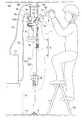
図1に示すように、回転工具ガイド機構1は、ドリル装置Sを支持して下方から上方に向かう上向き作業をガイドするものである。この回転工具ガイド機構1は、ガイド支柱2と、支柱長調整機構30と、ドリル装置Sを支持する工具取付機構40と、保持機構50と、ハンドル機構60とを備えている。なお、ドリル装置Sは、ここでは、ドリルdr先端から潤滑液としての潤滑水を供給し、ドリルdr先端から降下する切削粉と潤滑水とが混ざった排液水を外部に排水するろ過循環装置71に接続されて動作する構成として説明する。DESCRIPTION OF EMBODIMENTS Hereinafter, embodiments for carrying out the present invention will be described in detail with reference to the drawings. Here, the description will be made assuming that the drilling operation is performed by using a drill device as a rotary tool and guided by a rotary tool guide mechanism.
As shown in FIG. 1, the rotary tool guide mechanism 1 supports a drill device S and guides an upward operation from below to above. The rotary tool guide mechanism 1 includes a
図1および図2に示すように、ガイド支柱2は、作業面MS及び設置面Hsに亘る設置領域にドリル装置Sを支持するためのものである。このガイド支柱2は、プラスチックや、あるいは、鉄、ステンレス、アルミニウム合金等の金属で筒状に形成さており、ドリル装置Sの重量及び穴明作業を行うときの反力に対して強度を有する材料であればよい。このガイド支柱2は、本体支柱3とこの本体支柱3の上部に設けたスライド支柱4と、本体支柱3の下部に設けたベース支柱5とを備えている。そして、ガイド支柱2は、スライド支柱4が本体支柱3に、後記する支柱長調整機構30の第1調整手段10により支持され、また、ベース支柱5に本体支柱3が、後記する支柱長調整機構30の第2調整手段20を介して支持されている。 As shown in FIG. 1 and FIG. 2, the
図1に示すように、本体支柱3は、所定長さに形成された筒状体である。この本体支柱3は、上部にスライド支柱4が内側あるいは外側に嵌合することができるように筒状に形成されている。なお、本体支柱3の下部は、ここでは、第2調整手段20に保持できる構成であれば、限定されるものではない。 As shown in FIG. 1, the main body support |
スライド支柱4は、ここでは、本体支柱3の内側に挿入されるように嵌合して本体支柱3の長手方向に沿ってスライドするものである。このスライド支柱4は、本体支柱3の上部に第1調整手段10を介して支持されて作業面MSにその一端を当接させる。スライド支柱4は、その長手方向に後記する保持機構50の凹部51が所定間隔で形成されている。凹部51は、図2(b)に示すように、スライド支柱4の長手方向に溝長さとなり、周面から中心側に溝深さとなる溝の溝底面に丸穴を形成することで形成されている。また、スライド支柱4の下部側には、第1調整手段10の第1フランジ部11が柱周面から突出した状態で固定されている。 Here, the
ベース支柱5は、本体支柱3の下部側を支持して、作業面MSに対向する設置面Hsに当接して設置される。このベース支柱5は、第2調整手段20を介して本体支柱3を支持している。ベース支柱5の下部には、設置面Hsに当接する面積を大きくするサポートシュー6が設置角度を変えることができるように設けられている。
以上の構成を備えるガイド支柱2は、第2調整手段20を介してベース支柱5と本体支柱3とで大きな長さ調整を、行い、また、第1調整手段10を介して本体支柱3とスライド支柱4とで小さな長さ調整を行っている。The
The
支柱長調整機構30は、ガイド支柱2の長さを調整するためのものである。この支柱長調整機構30は、第1調整手段10と、第2調整手段20とを備えている。
第1調整手段10は、スライド支柱4を本体支柱3からスライド自在に支持して本体支柱3からのスライド長さ量を調整するものである。この第1調整手段10は、第1フランジ部11と、第2フランジ部12と、付勢手段18とを備えている。また、付勢手段18は、後記するように、支持アーム14と、支持レバー15と、回動軸16と、スライド支持環17と、コイルスプリング13とを備えている。The strut
The first adjusting means 10 adjusts the slide length amount from the
図2に示すように、第1フランジ部11は、付勢手段18からの付勢力をスライド支柱4に伝達するものである。この第1フランジ部11は、スライド支柱4の周面よりも側方に突出して固定されて、支持アーム14の一端を揺動自在に支持できるように構成されている。第1フランジ部11はスライド支柱4を中心として対向するように両側に突出する部分を有している。なお、第1フランジ部11は、ここでは、支持アーム14の一端を揺動できるようにアーム直径よりも大きく、かつ、アーム端部よりも小さく形成された開口により支持アーム14の一端を支持している。 As shown in FIG. 2, the
付勢手段18は、第1フランジ部11と第2フランジ部12の間に設けられ、第1フランジ部11を作業面MS側に付勢するためのものであり、第1フランジ部11に一端が支持される支持アーム14と、この支持アーム14の他端を一側で支持する支持レバー15と、この支持レバー15の他側に設けた回動軸16を支持するスライド支持環17と、弾性部材としてのコイルスプリング13とをここでは備えている。 The urging means 18 is provided between the
支持アーム14は、弾性部材としてのコイルスプリング13からの付勢力を第1フランジ部11に伝達するものである。この支持アーム14は、その一端が第1フランジ部11に揺動自在に接続され、その他端が支持レバー15に回動自在に接続されている。支持アーム14の一端は、アーム径よりも大きな直径となるように支持ピン14aが取り付けられている。支持アーム14の他端は、ここでは、アーム長手方向に直交する方向に折り曲げられ、支持アーム14の一側に回動自在となるように支持されている。支持アーム14は、スライド支柱4を間に挟んで第1フランジ部11の両側に1本ずつ設けられている。 The
支持レバー15は、コイルスプリング13の付勢力を支持アーム14と共に第1フランジ部11に伝達し、また、その姿勢によっては伝達しないようにするものである。この支持レバー15は、レバー本体15aと、このレバー本体15aから段差を付けて設けた取手15bとを有している。レバー本体15aは、その一側に支持アーム14の他端を回動自在に支持し、その他側に回動軸16が設けられている。このレバー本体15aは、本体支柱3を間に挟んだ両側に対向して2つの部材が設けられ、その両側の部材を取手15bが接続するように構成されている。取手15bは、回動軸16を回動支点としてレバー本体15aの位置を操作するためのものである。支持レバー15は、レバー本体15aの回動軸16を通る長軸線の方向を、本体支柱3の軸線方向に沿った位置及び沿っていない位置に、その姿勢を変えるように回動する。支持レバー15が本体支柱3の軸線方向に沿う姿勢(図2(b)参照)であると、支持アーム14の軸線方向も本体支柱3の軸線方向に沿うようになる。また、支持レバー15が本体支柱3の軸線方向に沿っていない姿勢(図2(a)参照)であると、支持アーム14の軸線方向も本体支柱3の軸線方向に対して角度を付けて外れるようになる。 The
回動軸16は、本体支柱3の両側に位置するレバー本体15aの基端側に回動自在に設けられている。回動軸16は、支持レバー15の回動支点となっている。そして、この回動軸16は、本体支柱3を中心にして両側から、本体支柱3に設けたスライド支持環17に支持されている。
スライド支持環17は、回動軸16を支持し、本体支柱3に沿って移動自在に設けられている。このスライド支持環17は、コイルスプリング13の先端が当接して常に上方に付勢力が働くように設置されている。
コイルスプリング13は、支持アーム14、支持レバー15及びスライド支持環17を介して第1フランジ部11を上方に付勢するものである。このコイルスプリング13は、スライド支持環17と第2フランジ部12の間で本体支柱3に巻き付けて設けられ、スライド支持環17を常に作業面MS側に付勢するように構成されている。
第2フランジ部12は、本体支柱3の上部側に固定して設けられている。この第2フランジ部12は、本体支柱3の周面から側方に突出してフランジが形成されている。なお、第2フランジ部12は、コイルスプリング13の下端を支持することができる構成であれば、本体支柱3と一体に設けられる必要はなく、締結バンドのように本体支柱3の所定の位置に着脱自在に取り付けられる構成であっても構わない。The
The
The
The
以上のように構成された第1調整手段10は、つぎのように操作される。
図2(a)に示すように、第1調整手段10では、支持レバー15の取手15bを操作することで、回動軸16を回動支点として、レバー本体15aの長軸線を本体支柱3の軸線方向に沿ってない位置に移動させることで、支持アーム14の軸線方向を本体支柱3の軸線方向とは異なる位置とする。この状態では、第1調整手段では、コイルスプリング13でスライド支持環17を押しても、支持アーム14及び支持レバー15が本体支柱3の軸線方向に沿っていないので、第1フランジ部11を付勢することができないか、付勢する力は小さい。
また、図2(b)に示すように、第1調整手段10では、支持レバー15のレバー本体15aの長軸線を本体支柱3の軸線方向に沿った位置に移動させると、支持アーム14の軸線方向が本体支柱3の軸線方向に沿った状態となるので、スライド支持環17、支持レバー15及び支持アーム14を介して、コイルスプリング13の付勢力が第1フランジ部11に伝達される。したがって、第1調整手段10では、本体支柱3からスライド支柱4をコイルスプリング13の付勢力で作業面MSに常に押圧することができる。The first adjusting means 10 configured as described above is operated as follows.
As shown in FIG. 2A, in the first adjusting means 10, by operating the
Further, as shown in FIG. 2B, in the first adjusting means 10, when the major axis of the lever
図1及び図3に示すように、第2調整手段20は、本体支柱3をベース支柱5の長手方向に沿ってベース支柱5の範囲において所定位置に支持するものである。この第2調整手段20は、ベース支柱5に本体支柱3を支持した状態で、ベース支柱5に対して本体支柱3の上下方向の長さを調整している。図3に示すように、第2調整手段20は、ベース支柱5の下部側を固定する支柱保持部(保持部)21と、この支柱保持部21に支持されてベース支柱5に挿通される上部挿通部25と、支柱保持部21に支持されてベース支柱5に挿通され上部挿通部25とは離間して設けた下部挿通部26と、支柱保持部21にその一端側を揺動自在に支持されてベース支柱5に挿通される係合片27と、この係合片27を上部挿通部25側に付勢するベースコイルスプリング(コイルスプリング)29とを備えている。なお、第2調整手段20は、ここでは、ガイド挿通部24が上部挿通部26及び下部挿通部26の間に設けられている。 As shown in FIGS. 1 and 3, the second adjusting means 20 supports the
支柱保持部21は、本体支柱3の下部を保持して固定するためのものである。この支柱保持部21は、本体支柱3の下部を挿入して紙面左右方向及び下方向の移動を規制するための規制フレーム23と、この規制フレーム23に挿入した本体支柱3の下部側面を着脱自在に固定する固定ネジ部22と、を備えている。
規制フレーム23は、所定の大きさの面状に形成された本体フレーム23aと、この本体フレーム23aの一側に帯状に形成され本体支柱3が挿通される側面フレーム23bと、挿通された本体支柱3の下端に当接して支持する下部フレーム23cとを備えている。The
The
固定ネジ部22は、側面フレーム23bに対面する位置に設けたネジ固定フレーム22cと、このネジ固定フレーム22c及び側面フレーム23bを貫通して前記本体支柱3の側面を支持する固定ネジ22bと、この固定ネジ22bを本体支柱3に当接離間自在に操作するネジ操作ハンドル22aとを備えている。固定ネジ部22は、ネジ操作ハンドル22aを回転させることで固定ネジ22bを本体支柱3の側面に当接離間させるように動作する。 The fixing
上部挿通部25は、本体フレーム23aの上端から側方に突出して本体フレーム23aと一体に形成されている。この上部挿通部25は、ベース支柱5を挿通させる挿通穴が形成されている。
下部挿通部26は、本体フレーム23aの下端から側方に突出して本体フレーム23aと一体に形成されている。この下部挿通部26は、ベース支柱5を挿通させる挿通穴が形成されている。
上部挿通部25及び下部挿通部26の間には、ガイド挿通部24が本体フレーム23aの中段から側方に突出して本体フレーム23aと一体に形成されている。このガイド挿通部24は、挿通穴が形成され、上部挿通部25及び下部挿通部26よりも側方に大きく突出するように構成されている。The
The
Between the
係合片27は、ガイド挿通部24と下部挿通部26との間で、その一端が本体フレーム23aに揺動自在に支持されている。そして、係合片27は、ベース支柱5を挿通する挿通係合穴28が形成されている。この挿通係合穴28は、係合片27が10度以上傾斜できるようにベース支柱5の直径よりも大きな穴径に形成されている。
ベースコイルスプリング29は、係合片27を上方に付勢するためのものである。このベースコイルスプリング29は、係合片27と下部挿通部26との間でベース支柱5に巻き付けて設けられている。One end of the
The
以上のように構成された第2調整手段20は、次のように操作される。作業者は、図3(a)に示すように、本体支柱3を、下部を支柱保持部21の本体フレーム23aと側面フレーム23bの間に挿通させて下部フレーム23cに当接させる。そして、作業者は、第2調整手段20の固定ネジ部22のネジ操作ハンドル22aを回転させることで、固定ネジ22bの先端を本体支柱3の側面に当接させて固定する。そして、作業者は、第2調整手段20の係合片27をベースコイルスプリング29に抗して水平にした状態で、支柱保持部21をベース支柱5に沿って移動させて所定位置まで移動する。なお、第2調整手段20は、ベース支柱5に沿って、上方に移動させるときには、係合片27が傾斜した状態であっても移動することができ、下方に移動させるときのみに係合片27を水平にする必要がある。さらに、図3(b)に示すように、作業者は、所定位置で係合片27をベースコイルスプリング29により上方に付勢された状態とすることで、係合片27を一側に揺動させ傾斜させる。これにより、第2調整手段20は、係合片27が傾斜することで、挿通係合穴28のベース支柱5に当接する内周部分がベース支柱5の側面に係合して係合片27の位置が固定される。したがって、本体支柱3は、第2調整手段20によりベース支柱5に沿った所定の位置で保持される。 The 2nd adjustment means 20 comprised as mentioned above is operated as follows. As shown in FIG. 3A, the operator causes the lower part of the
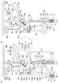
図1及び図4に示すように、工具取付機構40は、ドリル装置S等の回転工具を着脱自在に取り付けるものである。この工具取付機構40は、スライド支柱4に離間して設けた移動支持脚としての第1脚部41及び第2脚部42と、この第1脚部及び第2脚部42から側方に突出して連続して一体に形成された取付接続部43と、この取付接続部43に連続して形成した工具保持部44と、を備えている。なお、工具取付機構40は、ここでは、ドリル装置Sのドリルdrをガイドすると共に、切粉を落下させないための工具先端ガイド部48を先端ガイド支持部49により支持している。先端ガイド支持部49は、工具先端ガイド部48を支持するガイド支持板47と、このガイド支持板47をスライド支柱4の先端側に固定して支持する支持板固定部46とを備えている。 As shown in FIGS. 1 and 4, the
第1脚部41及び第2脚部42は、環状に形成されスライド支柱4に挿通してスライド支柱4の長手方向に移動自在に設けられている。そして、第1脚部41及び第2脚部42は、互いに離間して設置され同一直線上に配置されている。
取付接続部43は、第1脚部41及び第2脚部42から連続して形成されると共に、工具保持部44とが連続して一体に形成されている。この取付接続部43は、後記するハンドル機構60のハンドル作用軸61が設けられるように構成されている。The
The
図5に示すように、工具保持部44は、ドリル装置S等の回転工具が取り付けられる部位である。この工具保持部44は、取付接続部43から側方に突出してC字状のC環部として形成され、C開口の先端部分に設けたボルト締付部44aのボルトにより着脱自在に取付冶具45を保持するように構成されている。そして、ここでは、工具保持部44の下方からC環部内に、取付冶具45を介してドリル装置Sが着脱自在に固定されるように構成されている。取付冶具45は、上部円環部45cと、この上部円環部45cよりも大きな下部円環部45aと、この下部円環部45aから下方に突出する接続ボルト45bと、この接続ボルト45bに螺合されるナット45dと、を有している。なお、接続ボルト45bは、柱体の上下にオスネジが突出して設けられている。 As shown in FIG. 5, the
したがって、取付冶具45は、ドリル装置Sのドリルdrを挿通した状態で、接続ボルト45bの一方のオスネジを下部円環部45aの下面に螺合し、接続ボルト45bの他方のオスネジをドリル装置Sの取付ホルダScの穴に挿通させて接続ナット45dにより締め付けることで、ドリル装置Sに取り付けられる。そして、ドリル装置Sに取り付けた取付冶具45を工具保持部44に取り付けることでドリル装置Sを設置する。ここでは、工具保持部44は、取付冶具45の上部円環部45cを当該工具保持部44のC環部内に挿入して、ボルト締付部44aのボルトにより締め付けることで、ドリル装置Sを取り付けた取付冶具45を固定している。 Therefore, the
なお、ここでは、取付冶具45のサイズを変えることでドリル装置Sの種類を変えることができるように構成されている。また、工具保持部44のボルト締付部44aから上方に回転止板44bが設けられている。この回転止板44bは、後記するドリル装置Sの吸水供給部の一部に当接して回転を防止するためのものである。 Here, the type of the drill device S can be changed by changing the size of the mounting
また、ドリル装置Sは、潤滑水を供給しながら作業を行うため、図1に示すように、作業面MSに工具先端ガイド部48を使用している。そのため、工具取付機構40は、工具先端ガイド部48をガイド支持板47及び、ガイド支持板47をスライド支柱4に固定する支持板固定部46を有している。ガイド支持板47は、その一端に工具先端ガイド部48を支持する支持部を有すると共に、ドリルdrが回転したときに接触しないようにドリル穴が形成されている。また、ガイド支持板47は、他端にスライド支柱4に挿通する挿通穴が形成されビス(支持板固定部)46によりスライド支柱4の所定位置で着脱自在に固定されるように構成されている。 In addition, the drill device S uses a tool
図1及び図4に示すように、保持機構50は、工具取付機構40に当接して工具取付機構40をスライド支柱4に支持するためのものである。この保持機構50は、スライド支柱4に設けた凹部51と、この凹部51に着脱自在に係合する固定ピン53と、この固定ピン53を支持する固定ピンガイド52と、を備えている。凹部51は、既に説明したようにスライド支柱4の長手方向に沿って形成されている。 As shown in FIGS. 1 and 4, the holding
固定ピンガイド52は、スライド支柱4に挿通するように円環状に形成されている。この固定ピンガイド52は、スライド支柱4の取付接続部43側に後記するハンドル機構60のハンドル支点軸62が支持され、このハンドル支点軸62にスライド支柱4を介して対向する位置に固定ピン53の挿通穴52aが形成されている。なお、挿通穴52aの内側には、ピン用バネ55を取り付けるガイド板55aがスライド自在に案内され、ピン本体54に固定して取り付けられている。固定ピン53は、ピンレバー58の操作により凹部51に着脱自在に係合するように構成されている。この固定ピン53は、ピン本体54と、このピン本体54を凹部51側に付勢するピン用バネ55及びガイド板55aと、ピン本体54の基端側に設けたピン支持軸部56と、このピン支持軸部56が取り付けられるピンブロック体57と、このピンブロック体57が支持されるピンレバー58とを備えている。
なお、ピンブロック体57は、ピン本体54の両側に突出するピン支持軸部56を回動自在に支持している。このピンブロック体57は、ピンレバー58から内側に突出して短辺と長辺とからなる矩形に形成されている。The fixed
Note that the
このように構成された保持機構50は、図4(a)に示すように、ピンレバー58の操作によりピンブロック体57の長辺がスライド支柱4に平行な状態であると、ピンブロック体57に支持されているピン支持軸部56から凹部51までのピン本体54の距離がピン用バネ55により付勢されて最小となり、ピン本体54の先端が凹部51に係合する。また、図4(b)に示すように、ピンレバー58の操作によりピンブロック体57の短辺がスライド支柱4に平行な状態であると、ピンブロック体57に支持されているピン支持軸部56から凹部51までのピン本体54の距離がピン用バネ55に抗して最大となり、ピン本体54の先端が凹部51から離間する。 As shown in FIG. 4A, the holding
図4及び図5に示すように、ハンドル機構60は、梃子を利用して工具取付機構40に取り付けたドリル装置Sを作業面MSに対して上昇あるいは降下させるためのものである。このハンドル機構60は、取付接続部43に設けたハンドル作用軸61と、このハンドル作用軸61に対して支点となるように保持機構50の固定ピンガイド52に設けたハンドル支点軸62と、このハンドル支点軸62を支点として前記ハンドル作用軸61に接続されている工具取付機構40(46,47を除く)をスライド支柱4に沿って移動させるハンドルレバー67とを備えている。なお、ハンドルレバー67は、ここでは、ハンドル作用軸61及びハンドル支点軸62が接続され、ハンドル支点軸62に係合する長穴63が形成された直線状の先端ハンドル64と、この先端ハンドル64に介在接続部65を介して接続される操作レバー66とを有しており、先端ハンドル64の長手方向における軸線方向から、操作レバー66の長手方向における軸線方向の取付角度を変えるようにしている。 As shown in FIGS. 4 and 5, the
また、ハンドル機構60は、図5(a)に示すように、ここでは、ハンドル作用軸61が先端ハンドル64の側面から突出して設けられ、その先端ハンドル64の側面から突出した軸部分にハンドル用コイルスプリング(スプリング部材)68が取り付けられている。そして、ハンドル用コイルスプリング68は、その一端を取付接続部43の外側面に係止し、かつ、その他端を先端ハンドル64の側面に係止して、ハンドルレバー67が常に上方(作業面方向)に付勢されるように構成している。 Further, as shown in FIG. 5A, the
このハンドル機構60は、図5(a)に示すように、ハンドルレバー67を作業者がハンドル用コイルスプリング68の付勢力に抗して押し下げると、ハンドル支点軸62を支点としてハンドル作用軸61が接続されている工具取付機構40をスライド支柱4に沿って上方に移動させる。ここでは、保持機構50が第1脚部41の下端に当接する位置に固定されているので、ハンドルレバー67の一回の下方に下げるストローク動作で、第2脚部42の上端が保持機構50の下端に当接するまでスライド支柱4に沿って工具取付機構40が移動することができる。 As shown in FIG. 5 (a), when the
なお、ドリル装置Sは、図1に示すように、ドリルdrの基端側に潤滑液である潤滑水を供給する筒状の潤滑水供給体Stが設置されると共に、ドリルdrの先端側に排液水を回収する工具先端ガイド部48が設置される。なお、潤滑水供給体Stは、その側面から突出して、潤滑水を送る供給ホース72の接続管Spが形成されており、この接続管Spから送られてきた潤滑水をドリルdrに形成した供給孔(図示せず)からドリルdr内部を流通させ先端に供給するように構成されている。また、ドリル装置Sは、ドリルdrの先端から送り出した潤滑水と切粉とが混在した排液水が、ドリルdrと穿孔との間から降下してくると、工具先端ガイド部48で回収して排水ホース73からろ過循環装置71に送るように構成されている。工具先端ガイド部48は、図5(a)に示すように、円筒状で排液水を一時的に収納する共にドリルdrが回転しても排液水が漏れないように形成された筒状ガイド体48aと、この筒状ガイド体48aに収納している排液水を外部に送り出すための排水接続管48bとを備えている。 In the drill device S, as shown in FIG. 1, a cylindrical lubricating water supply St that supplies lubricating water as a lubricating liquid is installed on the proximal end side of the drill dr, and at the distal end side of the drill dr. A tool
そして、ドリル装置Sは、図1に示すように、ろ過循環装置71からポンプにより潤滑水が供給ホース72から潤滑水供給体Stに供給されると、ドリルdrの内部を流通してドリル先端から潤滑液が供給された状態で穴明作業が行われる。作業面MSにおいてドリルdrで穴明作業が始まると潤滑水に切粉が混在した排液水が発生する。そして、工具先端ガイド部48は、排水接続管48bに接続される排水ホース73を介してろ過循環装置71に排液水を送る。さらに、ろ過循環装置71で回収された排液水は、ろ過されて再度潤滑水として供給される。 Then, as shown in FIG. 1, when the lubricating water is supplied from the
以上の構成を備える回転工具ガイド機構1を使用して穴明作業を行う手順について図6(a)〜(f)を参照して説明する。なお、ここでは、ドリル装置Sを予め工具取付機構40に取り付けた状態で、ろ過循環装置71の供給ホース72及び排水ホース73を接続した状態(図6では図示せず、図1参照)として説明する。また、保持機構50は、固定ピン53が凹部51に係合し固定ピンガイド52で、工具取付機構40の第1脚部41をスライド支柱4に保持されている状態として説明する。 A procedure for performing a drilling operation using the rotary tool guide mechanism 1 having the above configuration will be described with reference to FIGS. Here, the drill device S is attached to the
はじめに、図6(a)に示すように、作業者は、回転工具ガイド機構1において、本体支柱3の先端にスライド支柱4を、第1調整手段10を介して支持した状態で、本体支柱3の下端をベース支柱5の第2調整手段20で支持して作業面MSの直下に配置する。なお、作業者は、サポートシュー6を片方の足で踏んだ状態で、第2調整手段20をベース支柱5に沿って上方に移動させることで、第2調整手段20の位置を調整することができる。なお、作業者は、係合片27をベースコイルスプリング29の付勢力に抗して平行にして、スライド支柱4の上端が作業面MSに当接するまで上方に移動させるように操作してもかまわない。 First, as shown in FIG. 6A, the operator supports the
そして、図6(b)に示すように、回転工具ガイド機構1において、第2調整手段20は、ベースコイルスプリング29の付勢力により係合片27を上方に付勢し、係合片27の傾斜した姿勢を保持することで、ベース支柱5を基準に本体支柱3の長さ調整を行って本体支柱3をベース支柱5で支持する。このとき、回転工具ガイド機構1において、第1調整手段10の支持レバー15は、支持位置から外された状態となっている。 As shown in FIG. 6B, in the rotary tool guide mechanism 1, the second adjusting means 20 urges the
つぎに、図6(c)に示すように、作業者は、回転工具ガイド機構1において、支持レバー15を本体支柱3に沿うように操作すると、支持レバー15の長さ、及び支持アーム14の長さ分だけ、コイルスプリング13が圧縮された状態となる。つまり、コイルスプリング13の付勢力がスライド支持環17を押して、支持レバー15、支持アーム14及び第1フランジ部11を押し上げることになり、スライド支柱4の上端で作業面MSを付勢して突っ張る。 Next, as shown in FIG. 6C, when the operator operates the
図6(c)に示すように、作業者は、回転工具ガイド機構1のガイド支柱2は、作業面MS及び設置面Hsに亘ってスライド支柱4が常に作業面MSに付勢された状態(結果としてベース支柱5も設置面Hsを押している状態)として設置されることになる。なお、図1に示すように、ろ過循環装置71は、設置面Hsに作業台Taを介して設置されることでポンプの動力が小さくて済む。 As shown in FIG. 6 (c), the operator is in a state where the
そして、図1及び図6(d)に示すように、回転工具ガイド機構1が設置されると、作業者は、例えば、踏み台Raに乗った状態で、ハンドル用コイルスプリング68に抗してハンドルレバー67を下方に移動させる。そうすると、ハンドルレバー67の操作により、梃子の原理で工具取付機構40をスライド支柱4に沿って上方に移動させ、ドリル装置Sの上昇により穴明作業を行う。なお、図1に示すように、穴明作業を行う場合、ドリルdrの先端から潤滑水が供給されて切粉と混ざった排液水となり工具先端ガイド部48から排水ホース73を介してろ過循環装置71に回収される。したがって、穴明作業を行う作業者は、ドリルの切粉の影響を受けることがない。また、回収された排液水は、ろ過循環装置71でろ過されて切粉と潤滑水が分離されて再びドリルdrの先端側に供給されることになる。 As shown in FIGS. 1 and 6D, when the rotary tool guide mechanism 1 is installed, for example, an operator handles the handle against the
ハンドルレバー67を下げる一回のストローク動作による穴明が一旦終わると、ドリル装置S及びろ過循環装置71のスイッチを止めて、ハンドルレバー67を図6(c)の状態に戻すことで、ドリル装置Sの位置も降下させる。そして、図6(e)及び図4に示すように、保持機構50の固定ピン53を凹部51から外し、固定ピンガイド52をドリルdrで穿孔した分だけ作業者が上方に移動させる。そして、ドリルdrの先端が穿孔端に当接した状態で、固定ピン53を凹部51に係合することで、固定ピンガイド52を工具取付機構40の第1脚部41の下端に当接した状態として、上方に移動してスライド支柱4に保持する。 Once the drilling by one stroke operation to lower the
再び、ドリル装置S及びろ過循環装置71のスイッチをオンにして、図6(f)に示すように、ハンドルレバー67をハンドル用コイルスプリング68に抗して下方に移動せることで、梃子の原理によりドリル装置Sを上昇させドリルdrにより穴明作業を行う。なお、穴明作業は、ドリル装置Sのドリルdrの長さでは足りない場合、図示しない接続シャンクを現在取り付けているドリルdrに継ぎ足してさらに行うことが可能となる。また、有効長の長いドリルに取り替えて穴明作業を行っても構わない。
なお、ドリル装置Sによる穴明作業を行うときには、ドリルdrの振動がハンドルレバー67に伝わりやすいので、例えば、コンクリートから鉄筋に変わる部位があってもその感触を作業者に伝えやすい状態で作業を行うことができる。また、従来のドリル装置Sと比較してドリルdrが長い構成とするものを使用する場合でも、一度、回転工具ガイド機構1を設置した位置で、ドリル装置Sの固定位置を段階的に移動させて作業ができ、コンクリートに長穴を開ける場合は特に作業効率が向上する。The switch of the drill device S and the
When drilling with the drill device S, the vibration of the drill dr is easily transmitted to the
一か所での穴明作業が終了して次の設置場所に回転工具ガイド機構1を移動する場合は、つぎのような操作により行う。
図4、図6(f)に示すように、ドリル装置S及びろ過循環装置71のスイッチを切り、保持機構50の固定ピン53を凹部51から外し、図6(b)に示すように、ドリルdrの先端が作業面の下になるようにする。そして、図6(b)に示すように、第1調整手段10のコイルスプリング13の付勢力に抗して支持レバー15を外すことで、コイルスプリング13の付勢力を緩和して、図6(a)に示すように、第2調整手段20を操作して本体支柱3の位置を下方に下げることで、ガイド支柱2をつぎの設置場所に移動できるようにすることができる。なお、図6(b)に示す状態であっても、作業者がスライド支柱4をコイルスプリング13に抗して下げることで、スライド支柱4の先端を作業面MSから外すことができる。When the rotary tool guide mechanism 1 is moved to the next installation place after the drilling operation at one place is completed, the following operation is performed.
As shown in FIGS. 4 and 6 (f), the drill device S and the filtration and
次の設置場所に移動しても、図6(a)〜(f)に示すように、回転工具ガイド機構1を作業面MS及び設置面Hsの間に簡単に固定することができる。なお、次の設置場所が近く、数センチの段差であれば、図6(b)に示す状態で回転工具ガイド機構1を移動して、支持レバー15の操作によりコイルスプリング13の伸縮範囲において、その数センチの段差を吸収してガイド支柱2を設置することが可能となる。 Even if it moves to the next installation place, as shown to Fig.6 (a)-(f), the rotary tool guide mechanism 1 can be easily fixed between the work surface MS and the installation surface Hs. If the next installation location is close and the step is several centimeters, the rotary tool guide mechanism 1 is moved in the state shown in FIG. The
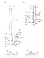
また、図7(a)、(b)に示すような回転工具ガイド機構100であっても構わない。なお、図7において、既に説明した構成は同じ符号を付してその説明を適宜省略する。
図7(a)、(b)に示すように、回転工具ガイド機構100では、ガイド支柱2Aと、支柱長調整機構130と、工具取付機構40と、保持機構50と、ハンドル機構60とを備えている。そして、回転工具ガイド機構100では、支柱長調整機構130の構成が図1の構成と異なっている。支柱長調整機構130は、スライド支柱4と本体支柱103との間に設けた第1調整手段110と、本体支柱103の下部側に沿ってスライドするベース支柱5Aを所定位置に固定自在に支持する第2調整手段120とを備えている。Moreover, the rotary
As shown in FIGS. 7A and 7B, the rotary
第1調整手段110は、図7(a)に示すように、嵌入筒体118と、この嵌入筒体118の上部側に設けられた第1係合手段111と、嵌入筒体118内に設けられる弾性部材113と、嵌入筒体118の下部側に設けられた第2係合手段112とを備えている。この第1調整手段110は、スライド支柱4を第2調整手段120と協同して作業位置に設置するためのものである。特に、第1調整手段110は、スライド支柱4を作業面MSに付勢してその付勢した位置でスライド支柱4を固定させるものである。 As shown in FIG. 7A, the first adjusting means 110 is provided in the
嵌入筒体118は、スライド支柱4の下部側及び本体支柱103の上部側を筒内に嵌入して支持するものである。この嵌入筒体118は、筒内にスライド支柱4の下端を当接して支持する係止部115と、第1係合手段111によりスライド支柱4を係合するための係合穴116と、第2係合手段112により本体支柱103を係合するための長穴117とを備えている。
係止部115は、スライド支柱4の下端に当接して支持するためのものである。この係止部115は、ここでは、筒内周から中心側に突出する突片により形成されている。なお、係止部115は、その中央側が貫通して形成されている。The
The locking
係合穴116は、第1係合手段111が蝶ネジ(蝶ボルト)等のつまみネジであるときにネジ穴として形成されている。つまり、嵌入筒体118の筒側面を貫通してその貫通した部分に雌ネジが形成されている。
長穴117は、第2係合手段112が蝶ネジ、クランプレバー等のつまみネジであるときに、ネジ部分が挿通されネジ頭部で穴周囲に当接して係合できるように形成されている。この長穴117は、後記する第2調整手段120の設置動作において、弾性部材113により作業面MS側に付勢されて移動するスライド支柱4の位置において、当該スライド支柱4を第2係合手段112で固定させるためのものである。The engaging
The
弾性部材113は、嵌入筒体118内に設置され、スライド支柱4を作業面MS側に付勢するものである。この弾性部材113は、例えば、コイルスプリングが用いられる。弾性部材113は、一端を嵌入筒体118の係止部115に当接させ、他端を本体支柱103の上端に当接させた状態で設置されている。 The
第1係合手段111は、スライド支柱4と嵌入筒体118とを着脱自在に係合させるものである。この第1係合手段111は、例えば、蝶ネジ(蝶ボルト)のようなつまみネジで構成されている。したがって、第1係合手段111は、嵌入筒体118にスライド支柱4を嵌入してスライド支柱4の下端が係止部115に当接させた状態で、嵌入筒体118の側壁に形成されている係合穴116の雌ネジ部分に螺合する。そして、第1係合手段111は、その先端をスライド支柱4の柱面に当接して押圧することで、スライド支柱4と嵌入筒体118とを係合している。 The first
また、第2係合手段112は、本体支柱103の上部側と嵌入筒体118とを着脱自在に係合させるものである。この第2係合手段112は、例えば、蝶ネジ(蝶ボルト)や、クランプレバー(先端にネジが形成されそのネジの上部側を90度に折れ曲げて取っ手が形成されているレバー)等のつまみネジで構成されている。また、第2係合手段112では、ネジの部分が本体支柱103の長穴よりも小径となるように形成されている。したがって、第2係合手段112では、作業位置に設置するときに、弾性部材113により作業面MS側に付勢されることでスライド支柱4が移動しても、その移動したスライド支柱4の位置でスライド支柱4と嵌入筒体118を係合することができる。 Moreover, the 2nd
本体支柱103は、スライド支柱4を支持すると共に、ベース支柱5Aに支持されている。この本体支柱103は、ここでは、上部側支柱103Aと、基部側支柱103Bとから構成されている。
上部側支柱103Aは、嵌入筒体118側となる一端側を中実に形成される中実部103aと、この中実部103aに支柱側面から中心に向かって形成した雌ネジ部103bと、この雌ネジ部103bより基部側支柱103B側に形成した中空部103cと、この中空部103cと基部側支柱103Bとが重なり合う位置に形成された係合穴103dとを備えている。この上部側支柱103Aは、スライド支柱4と基部側支柱103Bとを接続するものである。The
103 A of upper side support | pillars are the
基部側支柱103Bは、上部側支柱103Aの中空部103c側を嵌入して支持する上部側支柱嵌入部3aと、この上部側支柱嵌入部3aの下方に連続して中実に形成されたストッパ部3bと、このストッパ部3bに連続して中空に形成されたベース支柱スライド挿入部3cと、このベース支柱スライド挿入部3cの下端に開口して形成されたスライド開口部3dとを備えている。
上部側支柱嵌入部3aは、凹状に形成され、上部側支柱103Aの係合穴103dに対応する位置に形成されたネジ穴3eを備えている。したがって、上部側支柱嵌入部3aは、上部側支柱103Aの下端側が嵌入して係合穴103dとネジ穴3eとが一致した状態で、固定ネジ102によりネジ止めすることで、上部側支柱103Aを固定する。The base-
The upper side column
ストッパ部3bは、中実に形成されていることで、ベース支柱スライド挿入部3cにスライド開口部3dからベース支柱5Aが挿入されたときに、そのベース支柱5Aの先端が当接して、ベース支柱5Aのそれ以上の上方へのスライドを制限するものである。
ベース支柱スライド挿入部3cは、スライド開口部3dからストッパ部3bまでの範囲で、ベース支柱5Aのベース支柱先端部5aが内周面に沿って摺動できる大きさとなる中空に形成されている。
また、基部側支柱103Bの下端には、第2調整手段120が取り付けられている。Since the
The base strut
Moreover, the 2nd adjustment means 120 is attached to the lower end of the base side support |
第2調整手段120は、本体支柱103の基部側支柱103Bの内部に挿入されるベース支柱5Aを所定位置で着脱自在に支持するものである。この第2調整手段120は、基部側支柱103Bの下部に固定されベース支柱5Aを挿通する上部挿通部25と、この上部挿通部25を介在支持部23Aを介して離間させベース支柱5Aを挿通する下部挿通部26と、上部挿通部25及び下部挿通部26の間でベース支柱5Aに挿通した状態で、介在支持部23Aに一端側を揺動自在に支持される係合片27Aと、この係合片27Aに一端を当接させると共に下部挿通部26にその他端を当接させ、係合片27Aを上部挿通部25側に付勢するコイルスプリング29とを備えている。
なお、上部挿通部25の下面でスライド開口部3dに対向する部分には、ベース支柱5Aが抜けでないための抜止部23Bが取り付けられている。この抜止部23Bは、ベース支柱先端部5aの直径よりも開口を狭くするように内側に突出して取り付けられている。The second adjusting means 120 supports the
Note that a retaining
また、第2調整手段120は、ここでは、ガイド挿通部24が上部挿通部25及び下部挿通部26の間に設けられている。ガイド挿通部24は、介在支持部23Aの中段から側方に突出して介在支持部23Aと一体に形成されている。このガイド挿通部24は、挿通穴が形成され、上部挿通部25及び下部挿通部26よりも側方に大きく突出するように構成されている。さらに、係合片27Aの揺動自在に支持されている基端側には、介在支持部23Aに凸部123が形成されている。この凸部123は、係合片27Aが当接して傾斜しやすくするためのものである。なお、係合片27Aは、ガイド挿通部24よりも側方に飛び出しているので、作業者が係合片27Aを足で踏んで、ベース支柱5Aとの係合状態を外す操作がし易くなっている。 In the second adjustment means 120, the
第2調整手段120では、係合片27Aが、ベース支柱5Aを本体支柱103の支柱内からスライドさせた所定の位置で、コイルスプリング29に付勢されて一側に揺動して傾斜することで、ベース支柱5Aに当接する挿通係合穴28の内周面によりベース支柱5Aの外側面に係合する。そのため、第2調整手段120は、本体支柱103の内部に挿通されるベース支柱5Aを所定位置で固定して高さを調整した状態を維持することができる。 In the second adjusting means 120, the
ベース支柱5Aは、本体支柱103の下部側である基部側支柱103B内に沿ってスライド自在に挿入され、作業面MSに対向する設置面Hsに当接して設置される。このベース支柱5Aは、第2調整手段120を介して本体支柱103を支持している。ベース支柱5Aは、その一端となる先端にベース支柱先端部5aを備えている。ベース支柱先端部5aは、支柱径よりも大径に形成されており、基部側支柱103Bの下端に取り付けられた抜止部23Bにより抜け出さないように構成されている。ベース支柱5Aの他端となる下部には、設置面Hsに当接する面積を大きくするサポートシュー6Aが設置角度を変えることができるように設けられている。 The
なお、サポートシュー6Aは、本体サポート部6aと、補助サポート部6bとを備えている。補助サポート部6bは、作業者が足で踏んで本体支柱103を上方に移動させるときに使用されるものである。この補助サポート部6bは、本体サポート部6aの上面側に固定されている。 The
以上の構成を備えるガイド支柱2Aは、第2調整手段120を介してベース支柱5Aと本体支柱103とで大きな長さ調整を行い、また、第1調整手段110を介して本体支柱103とスライド支柱4とで小さな長さ調整を行っている。
以下、回転工具ガイド機構100を作業位置に設置する手順を図8を参照して説明する。なお、図8では使用される回転工具としてドリル装置Sが取り付けられた状態で説明するが、ドリル装置Sは、回転工具ガイド機構100を設置した後に取り付けることでも構わない。The
Hereinafter, a procedure for installing the rotary
図8(a)に示すように、作業者は、作業位置の設置面Hsに回転工具ガイド機構100のサポートシュー6Aを設置する。そして、図8(b)に示すように、サポートシュー6Aの補助サポート部6bを作業者が踏みながら本体支柱103を上方に持ち上げることで、ガイド支柱2A本体支柱103内に挿入されているベース支柱5Aをスライドさせて、ガイド支柱2A全体を伸長させ、スライド支柱4の先端を作業面MSに当接させる。 As shown in FIG. 8A, the worker installs the
次に、図8(c)に示すように、スライド支柱4の先端が作業面MSに当接した状態で、第2調整手段120の傾斜している係合片27Aに、ベース支柱5Aの側面が係合するために下方に多少下がる(数mm)が、第1調整手段110の弾性部材113がその下がった分を吸収して上方にスライド支柱4を付勢する。第1調整手段110の弾性部材113は、第2調整手段120でベース支柱5Aと本体支柱103とを係合した後であっても、スライド支柱4を上方に押し上げるように付勢した状態となっている。
このように、第2調整手段120の係合片27Aの係合及び第1調整手段110の弾性部材113により、ガイド支柱2Aは、作業面MS及び設置面Hsに突っ張った状態で設置される。Next, as shown in FIG. 8C, the side surface of the
In this manner, the
さらに、図8(d)に示すように、第1調整手段110のクランプレバーである第2係合手段112を作業者が回転させて、本体支柱103の係合穴103dに係合させる。ガイド支柱2Aでは、第2係合手段112を係合穴103dに係合することで、スライド支柱4と本体支柱103とを固定している。したがって、ガイド支柱2Aでは、作業者がドリル装置Sを移動させるときにハンドルレバー67を操作して大きな力がかかっても、スライド支柱4が下方に押し下げられることがない。
なお、保持機構50及びハンドル機構60等を用いてドリル装置Sを使用する動作は、既に説明した図6の動作と同じである。Further, as shown in FIG. 8 (d), the operator rotates the second engaging means 112, which is a clamp lever of the first adjusting means 110, and engages with the engaging
The operation of using the drill device S using the
以上説明したように、回転工具ガイド機構1は、支柱長調整機構30の第1調整手段10あるいは第2調整手段20のどちらか一方または両方を調整することで、設置場所の移動が簡単にでき、さらに、ハンドルレバー67を下方へ移動させる操作でドリル装置Sをスライド支柱4に沿って上昇させて穴明作業を行うことができるため、作業者の負担も軽減することができる。また、回転工具ガイド機構100は、支柱長調整機構130の第1調整手段110あるいは第2調整手段120のどちらか一方または両方を調整することで、設置場所の移動が簡単にでき、さらに、ハンドルレバー67を下方へ移動させる操作でドリル装置Sをスライド支柱4に沿って上昇させて穴明作業を行うことができるため、作業者の負担も軽減することができる。したがって、回転工具ガイド機構1は、下から上に向かって行う穴明作業に特に有効に使用することができる。 As described above, the rotary tool guide mechanism 1 can easily move the installation place by adjusting either one or both of the first adjusting means 10 and the second adjusting means 20 of the column
なお、回転工具ガイド機構1,100は、工具取付機構40が、第1脚部41及び第2脚部42を有する構成として説明したが、保持機構50で保持されることができれば、第1脚部41から第2脚部42まで連続する一つの筒状体の構成としても構わない。その場合、保持機構50は、筒状体の下端を保持する構成となる。
また、支柱長調整機構30の第1調整手段10は、コイルスプリング13からの付勢力を第1フランジ部11に伝えることができる構成であれば、第1フランジ部11と、コイルスプリング13と、第2フランジ部12の構成であっても構わない。In addition, although the rotary
Moreover, if the 1st adjustment means 10 of the support | pillar
なお、回転工具ガイド機構1,100が設置された状態で、ろ過循環装置71の供給ホース72を潤滑水供給体Stの接続管Spに接続すると共に、排水ホース73を工具先端ガイド部48の排水接続管48bに接続することとしてもよく接続するタイミングは問わない。
また、回転工具は、ドリル装置Sの替わりにコアビット装置等、であってもよく穿孔あるいは穴明けに使用される装置であれば限定されるものではない。また、作業方向は、設置場所にガイド支柱2を突っ張って使用することができる場所であれば、左右方向のような側面方向の作業や、あるいは下方向の作業に使用することができることはもちろんである。In addition, while the rotary
Further, the rotary tool may be a core bit device or the like instead of the drill device S, and is not limited as long as it is a device used for drilling or drilling. In addition, as long as the work direction is a place where the
さらに、スライド支柱4の凹部51は、固定ピン53が係合できれば、その形状、大きさ、間隔等は限定されるものではない。保持機構50の構成についても、スライド支柱4に着脱自在に保持される構成であれば限定されるものではない。
また、回転工具ガイド機構1では、ろ過循環装置71を使用して穴明作業を行うように説明したが、乾式による穴明作業では、ろ過循環装置71を使用する必要がない。また、ここでいう穴明作業とは、作業者がハンドルレバー67を操作して作業できる構成でれあば、直径が20cm以上のものや、あるいは、3cm未満のもの等、その大きさ穴径が限定されるものではない。Furthermore, as long as the fixing
In the rotary tool guide mechanism 1, it has been described that the drilling operation is performed using the
さらに、図7で説明した本体支柱103は、上部側支柱103A及び基部側支柱103Bの2つの部材である構成とした場合、上部側支柱103Aの長さの異なるもの予め準備しておくことで、設置面Hsから作業面MSまでの作業間隔が変わっても対応できるようになる。また、本体支柱103は、上部側支柱103A及び基部側支柱103Bとして説明したが、上部側支柱103A及び基部側支柱103Bを一体とした構成としても構わない。さらに、第1係合手段111及び第2係合手段112は、ネジの構成として説明したが、それぞれ係合穴に抜き差しできるピンであってもかまわず、着脱自在に係合することができるものであれば限定されるものではない。
なお、回転工具ガイド機構1,100は、本発明の趣旨に沿って適宜変更された構成により実現されるものであっても構わない。Furthermore, when the
The rotary
1,100 回転工具ガイド機構 2 ガイド支柱
3 本体支柱 4 スライド支柱
5 ベース支柱 6 サポートシュー
10,110 第1調整手段 11 第1フランジ部
12 第2フランジ部 13 コイルスプリング(弾性部材)
14 支持アーム 14a 支持ピン
15 支持レバー 15a レバー本体
15b 取手 16 回動軸
17 スライド支持環 18 付勢手段
20,120 第2調整手段 21 支柱保持部(保持部)
22 固定ネジ部 22a ネジ操作ハンドル
22b 固定ネジ 22c ネジ固定フレーム
23 規制フレーム 23a 本体フレーム
23b 側面フレーム 23c 下部フレーム
24 ガイド挿通部 25 上部挿通部
26 下部挿通部 27,27A 係合片
28 挿通係合穴
29 ベースコイルスプリング(コイルスプリング)
30,130 支柱長調整機構 40 工具取付機構
41 第1脚部(移動支持脚) 42 第2脚部(移動支持脚)
43 取付接続部 44 工具保持部
44a ボルト締付部 44b 回転止板
45 取付冶具 45a 下部円環部
45b 接続ボルト 45c 上部円環部
45d 接続ナット 46 支持板固定部
47 ガイド支持板 48 工具先端ガイド部
48a 筒状ガイド体 48b 排水接続管
50 保持機構 51 凹部
52 固定ピンガイド 52a 挿通穴
53 固定ピン 54 ピン本体
55 ピン用バネ 56 ピン支持軸部
57 ピンブロック体 58 ピンレバー
60 ハンドル機構 61 ハンドル作用軸
62 ハンドル支点軸 63 長穴
64 先端ハンドル 65 介在接続部
66 操作レバー 67 ハンドルレバー
68 ハンドル用コイルスプリング(スプリング部材)
71 ろ過循環装置 72 供給ホース
73 排水ホース Hs 設置面
MS 作業面 Ra 踏み台
S ドリル装置(回転工具) St 潤滑水供給体
Sp 接続管 Sc 取付ホルダ
Ta 作業台 dr ドリルDESCRIPTION OF SYMBOLS 1,100 Rotary
DESCRIPTION OF
22 fixing
29 Base coil spring (coil spring)
30, 130 Prop
43 mounting
71 Filtration /
Claims (11)
Translated fromJapanese前記作業面と対向する設置面との間に固定されるガイド支柱と、このガイド支柱の長さを付勢手段を介して調整する支柱長調整機構と、前記支柱長調整機構の上部側に前記ガイド支柱に沿って上下動自在に支持された工具取付機構と、この工具取付機構の前記ガイド支柱における位置を前記ガイド支柱に沿って変更可能に固定して保持する保持機構と、この保持機構で保持した前記工具取付機構を前記保持機構より上方となる前記ガイド支柱に沿って梃子により上下動させるハンドル機構と、を備え、
前記ガイド支柱は、本体支柱と、この本体支柱の下部側に沿って設けたベース支柱と、前記本体支柱の上部側に当該本体支柱に対してスライド自在に前記支柱長調整機構の付勢手段を介して設けたスライド支柱とを有し、
前記支柱長調整機構は、前記本体支柱の上部側と前記スライド支柱の下部側とに支持され、前記スライド支柱を上方に付勢して長さを調整する第1調整手段と、前記本体支柱の下部側と前記ベース支柱とに支持され、前記本体支柱を前記ベース支柱に沿って設定された所定の位置で当該本体支柱を保持する第2調整手段とを備え、
前記第1調整手段は、前記スライド支柱の下部側に固定して設けた第1フランジ部と、前記本体支柱の上部側に固定して設けた第2フランジ部と、前記第1フランジ部及び前記第2フランジ部の間で、前記第1フランジ部を前記作業面側に弾性部材を介して付勢するように設けた前記付勢手段とを有し、
前記付勢手段は、前記第1フランジ部に一端を揺動自在に支持される支持アームと、この支持アームの他端を一側に回動自在に支持する支持レバーと、この支持レバーの他側を回動自在に支持する回動軸と、この回動軸を支持し前記本体支柱にスライド自在に設けたスライド支持環と、このスライド支持環と前記第2フランジ部の間に設けた前記弾性部材とを有することを特徴とする回転工具ガイド機構。In the rotary tool guide mechanism that guides the rotary tool that performs drilling work toward the work surface,
A guide column fixed between the work surface and the installation surface facing the work surface, a column length adjustment mechanism that adjusts the length of the guide column via an urging means, and the upper side of the column length adjustment mechanism A tool mounting mechanism that is supported so as to be movable up and down along the guide column, a holding mechanism that fixes and holds the position of the tool mounting mechanism on the guide column along the guide column, and the holding mechanism. A handle mechanism that moves the held tool attachment mechanism up and down with a lever along the guide post above the holding mechanism, and
The guide strut includes a main body strut, a base strut provided along the lower side of the main body strut, and an urging means of the strut length adjusting mechanism slidable with respect to the main body strut on the upper side of the main body strut. throughand closed and a slide support postprovided,
The strut length adjusting mechanism is supported by the upper side of the main body column and the lower side of the slide column, and urges the slide column upward to adjust the length; and A second adjusting means supported by the lower side and the base column, and holding the body column at a predetermined position set along the base column;
The first adjusting means includes a first flange portion fixed to the lower side of the slide column, a second flange portion fixed to the upper side of the body column, the first flange unit, Between the second flange portions, the biasing means provided to bias the first flange portion to the work surface side via an elastic member,
The urging means includes a support arm whose one end is swingably supported by the first flange portion, a support lever which rotatably supports the other end of the support arm to one side, and other support levers. A rotation shaft that rotatably supports the side, a slide support ring that supports the rotation shaft and that is slidably provided on the main body column, and the slide support ring that is provided between the slide support ring and the second flange portion. rotary tool guide mechanism, characterized bychromatic and an elastic member.
前記作業面と対向する設置面との間に固定されるガイド支柱と、このガイド支柱の長さを付勢手段を介して調整する支柱長調整機構と、前記支柱長調整機構の上部側に前記ガイド支柱に沿って上下動自在に支持された工具取付機構と、この工具取付機構の前記ガイド支柱における位置を前記ガイド支柱に沿って変更可能に固定して保持する保持機構と、この保持機構で保持した前記工具取付機構を前記保持機構より上方となる前記ガイド支柱に沿って梃子により上下動させるハンドル機構と、を備え、
前記ガイド支柱は、本体支柱と、この本体支柱の下部側に沿って設けたベース支柱と、前記本体支柱の上部側に当該本体支柱に対してスライド自在に前記支柱長調整機構の付勢手段を介して設けたスライド支柱とを有し、
前記支柱長調整機構は、前記本体支柱の上部側と前記スライド支柱の下部側とに支持され、前記スライド支柱を上方に付勢して長さを調整する第1調整手段と、前記本体支柱の下部側と前記ベース支柱とに支持され、前記本体支柱を前記ベース支柱に沿って設定された所定の位置で当該本体支柱を保持する第2調整手段とを備え、
前記第1調整手段は、前記スライド支柱の下部側に固定して設けた第1フランジ部と、前記本体支柱の上部側に固定して設けた第2フランジ部と、前記第1フランジ部及び前記第2フランジ部の間で、前記第1フランジ部を前記作業面側に弾性部材を介して付勢するように設けた前記付勢手段とを有し、
前記第2調整手段は、ベース支柱に離間して挿通する上部挿通部及び下部挿通部と、この上部挿通部及び下部挿通部を支持して前記本体支柱の下端を前記ベース支柱に沿って保持する保持部と、前記上部挿通部及び前記下部挿通部の間で前記ベース支柱に挿通し前記保持部に一端側を揺動自在に支持される係合片と、この係合片に一端を当接させると共に前記下部挿通部にその他端を当接させ、前記係合片を前記上部挿通部側に付勢するコイルスプリングとを備え、
前記係合片は、前記ベース支柱に挿通する挿通係合穴が形成され、前記コイルスプリングに付勢されて一側に揺動して傾斜することで、前記ベース支柱に当接する挿通係合穴の内周面により前記ベース支柱の外側面に係合することを特徴とする回転工具ガイド機構。In the rotary tool guide mechanism that guides the rotary tool that performs drilling work toward the work surface,
A guide column fixed between the work surface and the installation surface facing the work surface, a column length adjustment mechanism that adjusts the length of the guide column via an urging means, and the upper side of the column length adjustment mechanism A tool mounting mechanism that is supported so as to be movable up and down along the guide column, a holding mechanism that fixes and holds the position of the tool mounting mechanism on the guide column along the guide column, and the holding mechanism. A handle mechanism that moves the held tool attachment mechanism up and down with a lever along the guide post above the holding mechanism, and
The guide strut includes a main body strut, a base strut provided along the lower side of the main body strut, and an urging means of the strut length adjusting mechanism slidable with respect to the main body strut on the upper side of the main body strut. And a slide support provided through
The strut length adjusting mechanism is supported by the upper side of the main body column and the lower side of the slide column, and urges the slide column upward to adjust the length; and A second adjusting means supported by the lower side and the base column, and holding the body column at a predetermined position set along the base column;
The first adjusting means includes a first flange portion fixed to the lower side of the slide column, a second flange portion fixed to the upper side of the body column, the first flange unit, between the second flange portion,it has a said biasing means provided to bias said first flange portion via an elastic member to said workingsurface,
The second adjusting means supports an upper insertion portion and a lower insertion portion that are spaced apart from the base column, and supports the upper insertion portion and the lower insertion portion, and holds the lower end of the main body column along the base column. A holding portion, an engagement piece that is inserted into the base column between the upper insertion portion and the lower insertion portion and is supported by the holding portion so that one end side thereof is swingable, and one end abuts on the engagement piece And a coil spring that abuts the other end against the lower insertion portion and biases the engagement piece toward the upper insertion portion,
The engagement piece is formed with an insertion engagement hole that is inserted into the base column, and is biased by the coil spring and swings and tilts to one side so as to contact the base column.it characterized byengaging an outer surface of the base struts by the inner peripheral surfacerotating tool guidemechanism.
前記ハンドル機構は、前記工具取付機構の移動支持脚と工具保持部との間に設けたハンドル作用軸と、前記固定ピンガイドに設けられたハンドル支点軸と、前記ハンドル支点軸を支点として前記ハンドル作用軸に支持され、前記ハンドル作用軸の上下移動に伴って前記ハンドル支点軸を移動させる長穴が形成されたハンドルレバーと、を有することを特徴とする請求項3に記載の回転工具ガイド機構。The tool mounting mechanism includes a moving support leg that is supported by the slide column and moves along the longitudinal direction, and a tool holding portion that protrudes laterally from the moving support leg and holds the rotary tool detachably. Have
The handle mechanism includes a handle action shaft provided between a moving support leg and a tool holding portion of the toolmounting mechanism, a handle fulcrum shaft provided on the fixed pin guide, and the handle fulcrum as a fulcrum. The rotary tool guide mechanism according toclaim 3 , further comprising: a handle lever supported by an action shaft and formed with an elongated hole that moves the handle fulcrum shaft as the handle action shaft moves up and down. .
前記先端ガイド支持部は、工具先端ガイド部を支持するガイド支持板と、このガイド支持板を前記スライド支柱の上部側に着脱自在に固定する支持板固定部とを有し、
前記工具先端ガイド部は、前記回転工具に供給されて工具先端から送り出される潤滑液に切粉を含んで降下する排液水を一時的に収納する収納空間を有する筒状ガイド体と、この筒状ガイド体に突出して形成され前記収納空間に収納された排液水を外部の排水ホースに接続して排出する排水接続管とを備えることを特徴とする請求項1から請求項4のいずれか一項に記載の回転工具ガイド機構。The tool mounting mechanism includes a tip guide support portion that supports a tool tip guide portion that contacts the work surface and covers the tip of the rotary tool,
The tip guide support portion includes a guide support plate that supports the tool tip guide portion, and a support plate fixing portion thatremovably fixes the guide support plate to the upper side of the slide column,
The tool tip guide portion includes a cylindrical guide body having a storage space for temporarily storing drainage water that is supplied to the rotary tool and is sent out from the tool tip and containing chips and falling. any one ofclaims 1to 4 which is formed to protrude Jo guide body, characterized in that it comprises a drainage connection pipe for discharging by connecting the drainage water housed in the housing space outside the drainage hose The rotary tool guide mechanism according to one item.
前記作業面と対向する設置面との間に固定されるガイド支柱と、このガイド支柱の長さを付勢手段を介して調整する支柱長調整機構と、前記支柱長調整機構の上部側に前記ガイド支柱に沿って上下動自在に支持された工具取付機構と、この工具取付機構の前記ガイド支柱における位置を前記ガイド支柱に沿って変更可能に固定して保持する保持機構と、この保持機構で保持した前記工具取付機構を前記保持機構より上方となる前記ガイド支柱に沿って梃子により上下動させるハンドル機構と、を備え、
前記ガイド支柱は、本体支柱と、この本体支柱の下部側に沿って設けたベース支柱と、前記本体支柱の上部側に当該本体支柱に対してスライド自在に前記支柱長調整機構の付勢手段を介して設けたスライド支柱とを有し、
前記支柱長調整機構は、前記本体支柱の上部側と前記スライド支柱の下部側とに支持され、前記スライド支柱を上方に付勢して長さを調整する第1調整手段と、前記本体支柱の下部側と前記ベース支柱とに支持され、前記本体支柱を前記ベース支柱に沿って設定された所定の位置で当該本体支柱を保持する第2調整手段とを備え、
前記第1調整手段は、前記スライド支柱の下部側と前記本体支柱の上部側とを嵌入する嵌入筒体と、この嵌入筒体に嵌入された前記スライド支柱の下部側と前記本体支柱の上部側の間で前記スライド支柱を上方に付勢する弾性部材と、この弾性部材に付勢された前記スライド支柱の下部側と前記嵌入筒体とを着脱自在に係合する第1係合手段と、前記本体支柱の上部側と前記嵌入筒体とを着脱自在に係合する第2係合手段とを有することを特徴とする回転工具ガイド機構。In the rotary tool guide mechanism that guides the rotary tool that performs drilling work toward the work surface,
A guide column fixed between the work surface and the installation surface facing the work surface, a column length adjustment mechanism that adjusts the length of the guide column via an urging means, and the upper side of the column length adjustment mechanism A tool mounting mechanism that is supported so as to be movable up and down along the guide column, a holding mechanism that fixes and holds the position of the tool mounting mechanism on the guide column along the guide column, and the holding mechanism. A handle mechanism that moves the held tool attachment mechanism up and down with a lever along the guide post above the holding mechanism, and
The guide strut includes a main body strut, a base strut provided along the lower side of the main body strut, and an urging means of the strut length adjusting mechanism slidable with respect to the main body strut on the upper side of the main body strut. And a slide support provided through
The strut length adjusting mechanism is supported by the upper side of the main body column and the lower side of the slide column, and urges the slide column upward to adjust the length; and A second adjusting means supported by the lower side and the base column, and holding the body column at a predetermined position set along the base column;
The first adjusting means includes a fitting cylinder that fits the lower side of the slide column and the upper side of the body column, a lower side of the slide column and an upper side of the body column that are fitted into the fitting cylinder. An elastic member that urges the slide column upward, and a first engagement means that removably engages the lower side of the slide column and the fitting cylinder urged by the elastic member, upper side and the fitting cylinder and the second engagement means andyou whereinrotating the tool guide mechanism to have a engaging detachably the said body posts.
前記嵌入筒体は、前記ネジに対応するネジ穴の少なくとも一方が筒体長手方向に沿って形成された長穴であり、前記長穴に対応する前記スライド支柱の下部側及び前記本体支柱の上部側のいずれか一方において、当該支柱に形成した前記ネジが螺合する雌ネジ部を備えることを特徴とする請求項7に記載の回転工具ガイド機構。The first engagement means and the second engagement means are screws;
The fitting cylinder is an elongated hole in which at least one of the screw holes corresponding to the screw is formed along the longitudinal direction of the cylinder, and the lower side of the slide column and the upper part of the body column corresponding to the elongated hole The rotary tool guide mechanism according toclaim 7 , further comprising: a female screw portion into which the screw formed on the support column is screwed.
前記上部側支柱と前記基部側支柱とは、互いに重なる位置で側面から固定手段により着脱自在に支持されていることを特徴とする請求項7又は請求項8に記載の回転工具ガイド機構。The main body column includes an upper column that fits into the fitting cylinder, and a base column that supports the upper column,
The rotary tool guide mechanism according toclaim 7 or 8 , wherein the upper support column and the base support column are detachably supported by fixing means from the side surface at positions where they overlap each other.
前記作業面と対向する設置面との間に固定されるガイド支柱と、このガイド支柱の長さを付勢手段を介して調整する支柱長調整機構と、前記支柱長調整機構の上部側に前記ガイド支柱に沿って上下動自在に支持された工具取付機構と、この工具取付機構の前記ガイド支柱における位置を前記ガイド支柱に沿って変更可能に固定して保持する保持機構と、この保持機構で保持した前記工具取付機構を前記保持機構より上方となる前記ガイド支柱に沿って梃子により上下動させるハンドル機構と、を備え、
前記ガイド支柱は、本体支柱と、この本体支柱の下部側に沿って設けたベース支柱と、前記本体支柱の上部側に当該本体支柱に対してスライド自在に前記支柱長調整機構の付勢手段を介して設けたスライド支柱とを有し、
前記支柱長調整機構は、前記本体支柱の上部側と前記スライド支柱の下部側とに支持され、前記スライド支柱を上方に付勢して長さを調整する第1調整手段と、前記本体支柱の下部側と前記ベース支柱とに支持され、前記本体支柱を前記ベース支柱に沿って設定された所定の位置で当該本体支柱を保持する第2調整手段とを備え、
前記第1調整手段は、前記スライド支柱の下部側に固定して設けた第1フランジ部と、前記本体支柱の上部側に固定して設けた第2フランジ部と、前記第1フランジ部及び前記第2フランジ部の間で、前記第1フランジ部を前記作業面側に弾性部材を介して付勢するように設けた前記付勢手段とを有し、
前記第2調整手段は、
前記本体支柱の下部に固定して前記ベース支柱を挿通する上部挿通部と、この上部挿通部を介在支持部を介して離間させ前記ベース支柱を挿通する下部挿通部と、前記上部挿通部及び前記下部挿通部の間で前記ベース支柱に挿通し前記介在支持部に一端側を揺動自在に支持される係合片と、この係合片に一端を当接させると共に前記下部挿通部にその他端を当接させ、前記係合片を前記上部挿通部側に付勢するコイルスプリングとを備え、
前記係合片は、前記ベース支柱に挿通する挿通係合穴が形成され、前記コイルスプリングに付勢されて一側に揺動して傾斜することで、前記ベース支柱に当接する前記挿通係合穴の内周面により前記ベース支柱の外側面に係合し、前記本体支柱の内部に挿入される前記ベース支柱を所定位置で着脱自在に支持することを特徴とする回転工具ガイド機構。In the rotary tool guide mechanism that guides the rotary tool that performs drilling work toward the work surface,
A guide column fixed between the work surface and the installation surface facing the work surface, a column length adjustment mechanism that adjusts the length of the guide column via an urging means, and the upper side of the column length adjustment mechanism A tool mounting mechanism that is supported so as to be movable up and down along the guide column, a holding mechanism that fixes and holds the position of the tool mounting mechanism on the guide column along the guide column, and the holding mechanism. A handle mechanism that moves the held tool attachment mechanism up and down with a lever along the guide post above the holding mechanism, and
The guide strut includes a main body strut, a base strut provided along the lower side of the main body strut, and an urging means of the strut length adjusting mechanism slidable with respect to the main body strut on the upper side of the main body strut. And a slide support provided through
The strut length adjusting mechanism is supported by the upper side of the main body column and the lower side of the slide column, and urges the slide column upward to adjust the length; and A second adjusting means supported by the lower side and the base column, and holding the body column at a predetermined position set along the base column;
The first adjusting means includes a first flange portion fixed to the lower side of the slide column, a second flange portion fixed to the upper side of the body column, the first flange unit, Between the second flange portions, the biasing means provided to bias the first flange portion to the work surface side via an elastic member,
The second adjusting means includes
An upper insertion part that is fixed to the lower part of the main body column and is inserted through the base column, a lower insertion unit that is inserted through the base column by separating the upper insertion unit via an intervening support unit, the upper insertion unit, and the An engagement piece that is inserted into the base column between the lower insertion portions and is supported at one end side so as to be swingable by the interposition support portion, and has one end abutting on the engagement piece and the other end on the lower insertion portion A coil spring that urges the engaging piece toward the upper insertion portion,
The engagement piece is formed with an insertion engagement hole that is inserted into the base column, and is urged by the coil spring to swing and tilt to one side so that the insertion engagement comes into contact with the base column. the inner peripheral surface of the hole engage the outer surface of the base struts, the said base struts which are inserted into the body posts, characterized in that detachably supported at a predetermined positionrotary tool guide mechanism.
前記作業面と対向する設置面との間に固定されるガイド支柱と、このガイド支柱の長さを付勢手段を介して調整する支柱長調整機構と、前記支柱長調整機構の上部側に前記ガイド支柱に沿って上下動自在に支持された工具取付機構と、この工具取付機構の前記ガイド支柱における位置を前記ガイド支柱に沿って変更可能に固定して保持する保持機構と、この保持機構で保持した前記工具取付機構を前記保持機構より上方となる前記ガイド支柱に沿って梃子により上下動させるハンドル機構と、を備え、
前記ガイド支柱は、本体支柱と、この本体支柱の下部側に沿って設けたベース支柱と、前記本体支柱の上部側に当該本体支柱に対してスライド自在に前記支柱長調整機構の付勢手段を介して設けたスライド支柱とを有し、
前記支柱長調整機構は、前記本体支柱の上部側と前記スライド支柱の下部側とに支持され、前記スライド支柱を上方に付勢して長さを調整する第1調整手段と、前記本体支柱の下部側と前記ベース支柱とに支持され、前記本体支柱を前記ベース支柱に沿って設定された所定の位置で当該本体支柱を保持する第2調整手段とを備え、
前記第1調整手段は、前記スライド支柱の下部側と前記本体支柱の上部側とを嵌入する嵌入筒体と、この嵌入筒体に嵌入された前記スライド支柱の下部側と前記本体支柱の上部側の間で前記スライド支柱を上方に付勢する弾性部材と、この弾性部材に付勢された前記スライド支柱の下部側と前記嵌入筒体とを着脱自在に係合する第1係合手段と、前記本体支柱の上部側と前記嵌入筒体とを着脱自在に係合する第2係合手段とを有し、
前記第2調整手段は、
前記本体支柱の下部に固定して前記ベース支柱を挿通する上部挿通部と、この上部挿通部を介在支持部を介して離間させ前記ベース支柱を挿通する下部挿通部と、前記上部挿通部及び前記下部挿通部の間で前記ベース支柱に挿通し前記介在支持部に一端側を揺動自在に支持される係合片と、この係合片に一端を当接させると共に前記下部挿通部にその他端を当接させ、前記係合片を前記上部挿通部側に付勢するコイルスプリングとを備え、
前記係合片は、前記ベース支柱に挿通する挿通係合穴が形成され、前記コイルスプリングに付勢されて一側に揺動して傾斜することで、前記ベース支柱に当接する前記挿通係合穴の内周面により前記ベース支柱の外側面に係合し、前記本体支柱の内部に挿入される前記ベース支柱を所定位置で着脱自在に支持することを特徴とする回転工具ガイド機構。In the rotary tool guide mechanism that guides the rotary tool that performs drilling work toward the work surface,
A guide column fixed between the work surface and the installation surface facing the work surface, a column length adjustment mechanism that adjusts the length of the guide column via an urging means, and the upper side of the column length adjustment mechanism A tool mounting mechanism that is supported so as to be movable up and down along the guide column, a holding mechanism that fixes and holds the position of the tool mounting mechanism on the guide column along the guide column, and the holding mechanism. A handle mechanism that moves the held tool attachment mechanism up and down with a lever along the guide post above the holding mechanism, and
The guide strut includes a main body strut, a base strut provided along the lower side of the main body strut, and an urging means of the strut length adjusting mechanism slidable with respect to the main body strut on the upper side of the main body strut. throughand closed and a slide support postprovided,
The strut length adjusting mechanism is supported by the upper side of the main body column and the lower side of the slide column, and urges the slide column upward to adjust the length; and A second adjusting means supported by the lower side and the base column, and holding the body column at a predetermined position set along the base column;
The first adjusting means includes a fitting cylinder that fits the lower side of the slide column and the upper side of the body column, a lower side of the slide column and an upper side of the body column that are fitted into the fitting cylinder. An elastic member that urges the slide column upward, and a first engagement means that removably engages the lower side of the slide column and the fitting cylinder urged by the elastic member, A second engaging means for detachably engaging the upper side of the main column and the fitting cylinder;
The second adjusting means includes
An upper insertion part that is fixed to the lower part of the main body column and is inserted through the base column, a lower insertion unit that is inserted through the base column by separating the upper insertion unit via an intervening support unit, the upper insertion unit, and the An engagement piece that is inserted into the base column between the lower insertion portions and is supported at one end side so as to be swingable by the interposition support portion, and has one end abutting on the engagement piece and the other end on the lower insertion portion A coil spring that urges the engaging piece toward the upper insertion portion,
The engagement piece is formed with an insertion engagement hole that is inserted into the base column, and is urged by the coil spring to swing and tilt to one side so that the insertion engagement comes into contact with the base column. A rotary tool guide mechanism that engages with an outer surface of the base column by an inner peripheral surface of a hole and detachably supports the base column inserted into the body column at a predetermined position.
Priority Applications (1)
| Application Number | Priority Date | Filing Date | Title |
|---|---|---|---|
| JP2014005805AJP6412313B2 (en) | 2013-05-28 | 2014-01-16 | Rotary tool guide mechanism |
Applications Claiming Priority (3)
| Application Number | Priority Date | Filing Date | Title |
|---|---|---|---|
| JP2013112215 | 2013-05-28 | ||
| JP2013112215 | 2013-05-28 | ||
| JP2014005805AJP6412313B2 (en) | 2013-05-28 | 2014-01-16 | Rotary tool guide mechanism |
Publications (2)
| Publication Number | Publication Date |
|---|---|
| JP2015006784A JP2015006784A (en) | 2015-01-15 |
| JP6412313B2true JP6412313B2 (en) | 2018-10-24 |
Family
ID=52337471
Family Applications (1)
| Application Number | Title | Priority Date | Filing Date |
|---|---|---|---|
| JP2014005805AActiveJP6412313B2 (en) | 2013-05-28 | 2014-01-16 | Rotary tool guide mechanism |
Country Status (1)
| Country | Link |
|---|---|
| JP (1) | JP6412313B2 (en) |
Families Citing this family (6)
| Publication number | Priority date | Publication date | Assignee | Title |
|---|---|---|---|---|
| CN108099031A (en)* | 2017-12-18 | 2018-06-01 | 郑州默尔电子信息技术有限公司 | A kind of sprocket chain strip drill hole on wall device for building |
| CN108381692B (en)* | 2018-02-09 | 2024-01-09 | 福建清芯科技有限公司 | Continuous molding production process of non-aldehyde plywood |
| CN109057390A (en)* | 2018-08-17 | 2018-12-21 | 中国十七冶集团有限公司 | A kind of top plate bar planting auxiliary device |
| CN110640239A (en)* | 2019-11-13 | 2020-01-03 | 重庆超力高科技股份有限公司 | Threading device |
| CN111923155B (en)* | 2020-07-20 | 2021-11-19 | 山东凯迪威家具有限公司 | Panel perforating device for furniture manufacture |
| CN114139407B (en)* | 2022-02-07 | 2022-05-10 | 中海油田服务股份有限公司 | Guiding force synthesizing method and device for rotary guiding equipment |
Family Cites Families (8)
| Publication number | Priority date | Publication date | Assignee | Title |
|---|---|---|---|---|
| JPS4863892U (en)* | 1971-11-17 | 1973-08-14 | ||
| JPS5942811U (en)* | 1982-09-14 | 1984-03-21 | 海老沢 邦広 | Ceiling surface drilling work device |
| JPS6029410U (en)* | 1983-08-04 | 1985-02-27 | 株式会社マキタ電機製作所 | drill support device |
| JPS6029411U (en)* | 1983-08-05 | 1985-02-27 | ナニワ建設機材株式会社 | drill stand |
| US5322397A (en)* | 1993-10-04 | 1994-06-21 | Spear James C | Apparatus for supporting a drill in an elevated position |
| EP0747180A1 (en)* | 1995-05-24 | 1996-12-11 | Armand Lang | Drilling support with feeding arrangement for hand-held drilling machine |
| JP3661498B2 (en)* | 1999-07-09 | 2005-06-15 | 日立プラント建設株式会社 | Auxiliary tool for drilling machine |
| JP3160447U (en)* | 2010-04-15 | 2010-06-24 | ナニワ建設機材株式会社 | Drill stand |
- 2014
- 2014-01-16JPJP2014005805Apatent/JP6412313B2/enactiveActive
Also Published As
| Publication number | Publication date |
|---|---|
| JP2015006784A (en) | 2015-01-15 |
Similar Documents
| Publication | Publication Date | Title |
|---|---|---|
| JP6412313B2 (en) | Rotary tool guide mechanism | |
| CA2714838C (en) | Wood working machine and suitable rip fence module | |
| CN215256059U (en) | Core drilling machine assembly | |
| JPH08332628A (en) | Punching stand equipped with automatic forward space device for punching machine | |
| US20080115701A1 (en) | Workbench for power tool | |
| US8865988B2 (en) | Cymbal holding structure, cymbal stand having the holding structure, and fastener used in the holding structure | |
| KR101961156B1 (en) | The Fishing cradle support frame | |
| US20080067315A1 (en) | Work table | |
| JP2010058272A (en) | Manhole inner wall cutter and tool for manhole inner wall cutter | |
| CN107598210B (en) | The continuously punched assembly line on workpiece | |
| KR101514568B1 (en) | lotation lock possible satellite assembly device and lotation lock devices for satellite assembly device | |
| KR200440426Y1 (en) | Torch Rotator for Pipe Welding Equipment | |
| JP2009006404A (en) | Clamping device | |
| KR20140086643A (en) | Surface grinding equipment for skid loader | |
| JP2007232103A (en) | Clamping device | |
| JP2007009644A (en) | Fixing device of manhole inner wall cutting machine | |
| AU2011101082A4 (en) | Drill holder | |
| JP2018104988A (en) | Supporting column apparatus | |
| KR20220131777A (en) | Clamp lever device for waterproof and dustproof of fishing rod support | |
| JP5228875B2 (en) | Hi-hat cymbal angle adjustment structure | |
| CN222034797U (en) | Chemical experiment clips | |
| PT1816717E (en) | Supply column | |
| KR200232110Y1 (en) | Portable Cutting Guide Bar | |
| JP7455875B2 (en) | Tension-fixed pillar | |
| KR102409882B1 (en) | Folding device for means of transportation |
Legal Events
| Date | Code | Title | Description |
|---|---|---|---|
| RD02 | Notification of acceptance of power of attorney | Free format text:JAPANESE INTERMEDIATE CODE: A7422 Effective date:20160707 | |
| A621 | Written request for application examination | Free format text:JAPANESE INTERMEDIATE CODE: A621 Effective date:20161216 | |
| A521 | Request for written amendment filed | Free format text:JAPANESE INTERMEDIATE CODE: A523 Effective date:20170214 | |
| A977 | Report on retrieval | Free format text:JAPANESE INTERMEDIATE CODE: A971007 Effective date:20171026 | |
| A131 | Notification of reasons for refusal | Free format text:JAPANESE INTERMEDIATE CODE: A131 Effective date:20171205 | |
| A521 | Request for written amendment filed | Free format text:JAPANESE INTERMEDIATE CODE: A523 Effective date:20180202 | |
| A131 | Notification of reasons for refusal | Free format text:JAPANESE INTERMEDIATE CODE: A131 Effective date:20180724 | |
| A521 | Request for written amendment filed | Free format text:JAPANESE INTERMEDIATE CODE: A523 Effective date:20180904 | |
| TRDD | Decision of grant or rejection written | ||
| A01 | Written decision to grant a patent or to grant a registration (utility model) | Free format text:JAPANESE INTERMEDIATE CODE: A01 Effective date:20180918 | |
| A61 | First payment of annual fees (during grant procedure) | Free format text:JAPANESE INTERMEDIATE CODE: A61 Effective date:20180928 | |
| R150 | Certificate of patent or registration of utility model | Ref document number:6412313 Country of ref document:JP Free format text:JAPANESE INTERMEDIATE CODE: R150 | |
| R250 | Receipt of annual fees | Free format text:JAPANESE INTERMEDIATE CODE: R250 | |
| R250 | Receipt of annual fees | Free format text:JAPANESE INTERMEDIATE CODE: R250 |