JP6411784B2 - 3D modeling equipment - Google Patents
3D modeling equipmentDownload PDFInfo
- Publication number
- JP6411784B2 JP6411784B2JP2014125077AJP2014125077AJP6411784B2JP 6411784 B2JP6411784 B2JP 6411784B2JP 2014125077 AJP2014125077 AJP 2014125077AJP 2014125077 AJP2014125077 AJP 2014125077AJP 6411784 B2JP6411784 B2JP 6411784B2
- Authority
- JP
- Japan
- Prior art keywords
- unit
- driving
- modeling apparatus
- dimensional modeling
- drive
- Prior art date
- Legal status (The legal status is an assumption and is not a legal conclusion. Google has not performed a legal analysis and makes no representation as to the accuracy of the status listed.)
- Active
Links
Images


Classifications
- Y—GENERAL TAGGING OF NEW TECHNOLOGICAL DEVELOPMENTS; GENERAL TAGGING OF CROSS-SECTIONAL TECHNOLOGIES SPANNING OVER SEVERAL SECTIONS OF THE IPC; TECHNICAL SUBJECTS COVERED BY FORMER USPC CROSS-REFERENCE ART COLLECTIONS [XRACs] AND DIGESTS
- Y02—TECHNOLOGIES OR APPLICATIONS FOR MITIGATION OR ADAPTATION AGAINST CLIMATE CHANGE
- Y02P—CLIMATE CHANGE MITIGATION TECHNOLOGIES IN THE PRODUCTION OR PROCESSING OF GOODS
- Y02P10/00—Technologies related to metal processing
- Y02P10/25—Process efficiency
Landscapes
- Powder Metallurgy (AREA)
Description
Translated fromJapanese本発明は、粉末を繰り返し層状に形成することによって三次元造形物を製造する三次元造形装置に関する。 The present invention relates to a three-dimensional modeling apparatus for manufacturing a three-dimensional modeled object by repeatedly forming powder in a layered manner.
従来、金属粉末の粉末層に収束したエネルギービームを照射して焼結体を形成する焼結動作を繰り返し行うことにより、複数の焼結体を重ね合わせてなる三次元造形物を製造する三次元造形装置が開示されている(特許文献1及び特許文献2参照)。 Conventionally, a three-dimensional structure that produces a three-dimensional structure formed by stacking a plurality of sintered bodies by repeatedly performing a sintering operation to form a sintered body by irradiating an energy beam focused on a powder layer of metal powder A modeling apparatus is disclosed (see
本発明は、精度及び生産性の高い三次元造形装置を提供することを目的としている。 An object of the present invention is to provide a three-dimensional modeling apparatus with high accuracy and productivity.
本発明にかかる一実施形態の三次元造形装置は、
支持フレームと、
前記支持フレームに支持される材料供給部と、
前記支持フレームに支持され、前記材料供給部から供給される材料が載置される1つの平面状のテーブルと、
前記テーブルを駆動する駆動部と、
前記テーブルの位置を測定する測定部と、
前記測定部の測定値に基づいて、前記駆動部を制御する制御部と、
を備え、
前記駆動部は、独立して駆動可能な第1駆動部及び第2駆動部を少なくとも有し、
前記測定部は、前記テーブルの位置をそれぞれ測定する第1測定部及び第2測定部を少なくとも有し、
前記制御部は、前記第1測定部及び前記第2測定部の各測定値に基づいて、前記第1駆動部及び前記第2駆動部をそれぞれ独立して制御する
ことを特徴とする。The three-dimensional modeling apparatus of one embodiment according to the present invention is
A support frame;
A material supply unit supported by the support frame;
One planar table on which the material supported by the support frame and supplied from the material supply unit is placed;
A drive unit for driving the table;
A measuring unit for measuring the position of the table;
A control unit for controlling the drive unit based on the measurement value of the measurement unit;
With
The drive unit has at least a first drive unit and a second drive unit that can be driven independently,
The measurement unit has at least a first measurement unit and a second measurement unit for measuring the position of the table, respectively.
The control unit controls the first driving unit and the second driving unit independently based on measurement values of the first measurement unit and the second measurement unit, respectively. To do.
本発明にかかる一実施形態の三次元造形装置は、
前記テーブルの指示移動量をあらかじめ入力する入力部と、
前記入力部から入力された指示移動量を記憶する記憶部と、
を備え、
前記制御部は、前記記憶部に記憶した指示移動量の分だけ前記テーブルを移動させる。The three-dimensional modeling apparatus of one embodiment according to the present invention is
An input unit for inputting in advance an instruction movement amount of the table;
A storage unit that stores an instruction movement amount input from the input unit;
With
The control unit moves the table by the indicated movement amount stored in the storage unit.
本発明にかかる一実施形態の三次元造形装置では、
前記制御部は、前記駆動部の状態信号がフィードバックされる。In the three-dimensional modeling apparatus of one embodiment according to the present invention,
The control unit feeds back a status signal of the driving unit.
本発明にかかる一実施形態の三次元造形装置は、
前記第1駆動部及び前記第2駆動部の各駆動力を前記テーブルにそれぞれ伝達する第1伝達部及び第2伝達部を有する伝達部をさらに備える。The three-dimensional modeling apparatus of one embodiment according to the present invention is
Further comprising a transmission section having afront Symbol first transmission section and a second transmission unit and transmits it to the table each driving force of the first driving unit and the second driving unit.
本発明にかかる一実施形態の三次元造形装置では、
前記第1測定部及び前記第2測定部は、前記テーブルと前記第1伝達部及び前記第2伝達部伝達部の支持位置に対応してそれぞれ配設される。In the three-dimensional modeling apparatus of one embodiment according to the present invention,
The first measurement unit and the second measurement unit are respectively disposed corresponding to the support positions of the table, the first transmission unit, and the second transmission unit transmission unit.
本発明にかかる一実施形態の三次元造形装置では、
前記駆動部は、独立して駆動可能な第3駆動部及び第4駆動部をさらに有し、
前記第1駆動部、前記第2駆動部、前記第3駆動部及び前記第4駆動部は、四角形を形成する位置に配置され、
前記伝達部は、前記第3駆動部及び前記第4駆動部の駆動力を前記テーブルに伝達する第3伝達部及び第4伝達部をさらに有し、
前記制御部は、前記第1駆動部、前記第2駆動部、前記第3駆動部、及び前記第4駆動部をそれぞれ独立して制御可能である。In the three-dimensional modeling apparatus of one embodiment according to the present invention,
The driving unit further includes a third driving unit and a fourth driving unit that can be driven independently,
The first driving unit, the second driving unit, the third driving unit, and the fourth driving unit are arranged at positions that form a quadrangle,
The transmission unit further includes a third transmission unit and a fourth transmission unit that transmit the driving force of the third driving unit and the fourth driving unit to the table,
The control unit can independently control the first drive unit, the second drive unit, the third drive unit, and the fourth drive unit.
本発明にかかる一実施形態の三次元造形装置は、
前記テーブルと共に移動するロッドと、
前記ロッドが所定の位置に到達した場合に接触するリミットスイッチと、
を備える。The three-dimensional modeling apparatus of one embodiment according to the present invention is
A rod that moves with the table;
A limit switch that contacts when the rod reaches a predetermined position;
Is provided.
本発明によれば、精度及び生産性の高い三次元造形装置を提供することが可能となる。 According to the present invention, it is possible to provide a three-dimensional modeling apparatus with high accuracy and productivity.
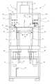
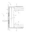
図1は、本発明にかかる一実施形態の三次元造形装置を示す図である。 FIG. 1 is a diagram showing a three-dimensional modeling apparatus according to an embodiment of the present invention.
本実施形態の三次元造形装置1は、材料供給部としてのエネルギービーム照射部2と、材料供給部としての粉末供給部3と、造形物載置部4と、を備える。エネルギービーム照射部2、粉末供給部3、及び造形物載置部4は、支持フレーム11に支持される。また、支持フレーム11の中間部分には、支持フレーム11の一部としての基準フレーム12が形成されている。 The three-
エネルギービーム照射部2は、エネルギービームEBを発生するビーム発生部21と、ビーム発生部21から照射されたエネルギービームEBの焦点位置を調整すると共に、2次元走査可能なビーム走査部22と、を有し、支持フレーム11上に載置される。なお、本実施形態では、ビーム操作部22は2次元走査するものであるが、ビームの焦点位置を上下方向にも動作可能な3次元走査するものであってもよい。 The energy
ビーム発生部21は、レーザ光又は電子ビーム等を発生するものが好ましい。エネルギービームEBが光の場合、ビーム走査部22は、レンズ等の光学素子を移動させて、光を後述するテーブル上の金属粉末Mに集光させると共に、テーブル41上を2次元走査する。一例として、エネルギービーム照射部2は、特許文献1に記載されたレーザ照射ユニットのような構成でよい。また、エネルギービームEBが電子ビームの場合、ビーム走査部22は、電子ビームを電磁場の制御によってフォーカスさせると共に、テーブル41上を2次元走査する。一例として、エネルギービーム照射部2は、特許文献2に記載された電子線を照射し案内させる装置のような構成でよい。 The
粉末供給部3は、金属粉末Mを一時的に貯留する粉末貯留部31と、金属粉末Mをテーブル上で均す均し部32と、外枠部33と、を有する。 The
粉末貯留部31は、支持フレーム11に保持される容器からなり、上方に金属粉末Mを注入する注入部31aを有し、下方に金属粉末Mを排出する排出部31bを有する。排出部31bは、金属粉末Mの排出量を調整できることが好ましい。 The
均し部32は、粉末貯留部31から排出された金属粉末Mをテーブル41上でスクレーパ等の部材を移動させることによって可能な限り高さが均等な平面を形成する部分である。なお、金属粉末Mを均す高さは調整できることが好ましい。 The leveling
外枠部33は、支持フレーム11に支持され、後述するテーブル41の外周に設置される。外枠部33には、均し部32が均した後の余分な金属粉末Mが移動してくる。これらの金属粉末Mは、粉末貯留部31に戻す図示しない循環部によって循環されることが好ましい。 The
なお、粉末供給部3には、排出部31bから排出された後、造形されなかったテーブル41上の金属粉末Mを粉末貯留部31に戻す図示しない循環部が形成されてもよい。 The
材料供給部は、本実施形態のようなエネルギービーム照射部2及び粉末供給部3に限らず、シート又はテープ状の樹脂、紙、又は金属等を接着する形態、液体を硬化させる形態、インクジェットヘッドを用いて固体又は液体を噴射して接着させる形態、フィラメントを堆積して溶接する形態、若しくは、金属粉末を溶接する形態等でもよい。 The material supply unit is not limited to the energy
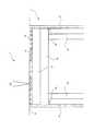
図2は、本実施形態の三次元造形装置の造形載置部を示す拡大図である。図3は、本実施形態の三次元造形装置の駆動伝達部の配置を示す概略図である。図4は、本実施形態の三次元造形装置の造形載置部を示す概略斜視図である。 FIG. 2 is an enlarged view showing a modeling placement part of the three-dimensional modeling apparatus of this embodiment. FIG. 3 is a schematic diagram showing the arrangement of the drive transmission unit of the three-dimensional modeling apparatus of this embodiment. FIG. 4 is a schematic perspective view showing a modeling placement part of the three-dimensional modeling apparatus of this embodiment.
造形物載置部4は、テーブル41と、スライダ42と、ボールねじ43と、減速部44と、テーブル駆動部45と、磁気センサ46と、磁気スケール47と、ロッド48と、リミットスイッチ49と、を有する。 The modeling
テーブル41は、スライダ42に支持される。テーブル41の上面は、平面で形成され、上面に図1に示した金属粉末Mが排出され、載置される。造形物は、テーブル41の外形よりも小さい造形領域41aに形成されることが好ましい。 The table 41 is supported by the
スライダ42は、上面でテーブル41を支持する。下方では、ボールねじ43に支持される。ボールねじ43は、減速部44を介して駆動部45に連結される。駆動部45は、サーボモータ又はその他のアクチュエータ等からなり、駆動部45が駆動することで、ボールねじ43が回転し、ボールねじ43の回転によってスライダ42が上下することで、テーブル41も上下する。ボールねじ43は、基準フレーム12を貫通することが好ましい。 The
本実施形態では、ボールねじ43、減速部44、駆動部45、磁気センサ46、及び磁気スケール47は、それぞれ4つ配設される。なお、ボールねじ43及び減速部44が伝達部を構成する。また、駆動部45と伝達部で駆動伝達部を構成する。なお、減速部44を用いず、駆動部45とボールねじ43の直動機構でもよい。直動機構の場合、バックラッシュを抑制できるので、より高精度に制御することが可能となる。 In the present embodiment, four
図3に示すように、第1ボールネジ43a、第2ボールネジ43b、第3ボールネジ43c、及び第4ボールネジ43dは、造形領域41aの外側で4つの角に対応してスライダ42に連結される。 As shown in FIG. 3, the
図4に示すように、第1駆動部45a、第2駆動部45b、第3駆動部45c、及び第4駆動部45dは、それぞれ第1減速部44a、第2減速部44b、第3減速部44c、及び第4減速部44dを介して第1ボールネジ43a、第2ボールネジ43b、第3ボールネジ43c、及び第4ボールネジ43dに連結される。 As shown in FIG. 4, the
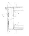
スライダ42の下方には、第1磁気センサ46a、第2磁気センサ46b、第3磁気センサ46c、及び第4磁気センサ46dが、第1ボールネジ43a、第2ボールネジ43b、第3ボールネジ43c、及び第4ボールネジ43dの支持位置に対応してそれぞれ取り付けられている。 Below the
なお、磁気センサ46は、測定部の一例である。測定部としては、この例の他に、スライダ42又は支持フレーム11の一方に発光部、他方に受光部を取り付けて距離を検出する光学的位置センサ又は超音波センサ等でもよい。特に、一方を基準フレーム12、他方をスライダ42に取り付けることが好ましい。また、これらのセンサは、第1ボールネジ43a、第2ボールネジ43b、第3ボールネジ43c、及び第4ボールネジ43dの支持位置に対応してそれぞれ取り付けられることが好ましい。または、図示しないモータエンコーダー等によってモータの回転角度をストローク量に換算し、磁気センサ46と共に用いて詳細に位置を検出してもよい。 The
そして、スライダ42の側方の支持フレーム11には、第1磁気センサ46a、第2磁気センサ46b、第3磁気センサ46c、及び第4磁気センサ46dに対向して、磁気目盛が付与された第1磁気スケール47a、第2磁気スケール47b、第3磁気スケール47c、及び第4磁気スケール47dが配設されている。 The
また、少なくとも第1ボールネジ43a、第2ボールネジ43b、第3ボールネジ43c、及び第4ボールネジ43dの1つには、ロッド48が取り付けられている。ロッド48は、テーブル41、スライダ42、及びボールねじ43と共に移動する。ロッド48の下方には、リミットスイッチ49が配設される。したがって、テーブル41、スライダ42、ボールねじ43、及びロッド48が下方への移動量が大きい場合或いは上方への移動量が大きいと、リミットスイッチ49が作動し、危険を知らせることが可能となる。 A
次に、本実施形態の三次元造形装置1の制御システムについて説明する。 Next, the control system of the three-
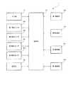
図5は、本実施形態の三次元造形装置1の制御システムを示す図である。 FIG. 5 is a diagram illustrating a control system of the three-
図5に示すように、本実施形態の三次元造形装置1は、入力部51、第1磁気センサ46a、第2磁気センサ46b、第3磁気センサ46c、第4磁気センサ46d、及び記憶部52から入力されたそれぞれの信号を制御部50が第1駆動部45a、第2駆動部45b、第3駆動部45c、及び第4駆動部45dを独立制御するものである。 As illustrated in FIG. 5, the three-
入力部51は、成形形状、成形圧力、成形速度等の情報を予め入力する。記憶部52は、入力部51から入力された情報及び造形工程等を記憶しており、制御部50にそれらの情報を出力する。それぞれの第1磁気センサ46a、第2磁気センサ46b、第3磁気センサ46c、及び第4磁気センサ46dは、対向する第1磁気スケール47a、第2磁気スケール47b、第3磁気スケール47c、及び第4磁気スケール47dの目盛りからそれぞれの変位又は速度等を測定し、制御部50に出力する。 The
第1駆動部45a、第2駆動部45b、第3駆動部45c、及び第4駆動部45dは、電流、回転速度、及び回転トルク等の信号を制御部50にフィードバックすることが好ましい。 The
次に、本実施形態の三次元造形装置1の作動について説明する。 Next, the operation of the three-
図6〜図9は、本実施形態の三次元造形装置の造形テーブル部の作動を示す拡大図である。 6 to 9 are enlarged views showing the operation of the modeling table unit of the three-dimensional modeling apparatus of this embodiment.
本実施形態の三次元造形装置1では、まず、図4に示した各駆動部45を駆動し、図6に示すように、テーブル41を下方に移動する。テーブル41の指示移動量は、図5に示した入力部51にあらかじめ入力し、記憶部52に記憶しておけばよい。 In the three-
ここで、本実施形態の三次元造形装置1では、記憶部52に記憶した指示移動量の分だけテーブル41を移動させている間に、第1駆動部45a、第2駆動部45b、第3駆動部45c、及び第4駆動部45dの電流、回転速度、及び回転トルク等の信号、並びに、第1磁気センサ46a、第2磁気センサ46b、第3磁気センサ46c、及び第4磁気センサ46dからの測定信号が制御部50に入力される。 Here, in the
制御部50は、これらの信号から第1駆動部45a、第2駆動部45b、第3駆動部45c、及び第4駆動部45dをそれぞれ独立して制御し、テーブル41を所定の姿勢に制御する。なお、本実施形態では、テーブル41を水平に制御する。 The
続いて、粉末貯留部31の排出部31bから金属粉末Mをテーブル41上に排出する。次に、均し部32によって金属粉末Mをテーブル41上で表面が水平になるように均等に均す。続いて、図1に示したエネルギービーム照射部2がエネルギービームEBを照射し、図7に示すように、金属粉末Mを焼結し、造形物M’の一部を形成する。 Subsequently, the metal powder M is discharged onto the table 41 from the
次に、再び図4に示した各駆動部45を駆動し、図8に示すように、テーブル41を下方に移動する。テーブル41の移動量は、図5に示した入力部51にあらかじめ入力し、記憶部52に記憶しておけばよい。 Next, each
ここで、先ほどと同様に、本実施形態の三次元造形装置1では、記憶部52に記憶した指示移動量の分だけテーブル41を移動させている間に、第1駆動部45a、第2駆動部45b、第3駆動部45c、及び第4駆動部45dの電流、回転速度、及び回転トルク等の信号、並びに、第1磁気センサ46a、第2磁気センサ46b、第3磁気センサ46c、及び第4磁気センサ46dからの測定信号が制御部50に入力される。 Here, similarly to the previous case, in the three-
制御部50は、これらの信号から第1駆動部45a、第2駆動部45b、第3駆動部45c、及び第4駆動部45dをそれぞれ独立に制御して、テーブル41を所定の姿勢に制御する。なお、本実施形態では、テーブル41を水平に制御する。 The
続いて、粉末貯留部31の排出部31bから金属粉末Mをテーブル41上に排出する。次に、均し部32によって金属粉末Mをテーブル41上で表面が水平になるように均等に均す。続いて、図1に示したエネルギービーム照射部2がエネルギービームEBを照射し、図9に示すように、金属粉末Mを焼結し、造形物M’の一部を形成する。 Subsequently, the metal powder M is discharged onto the table 41 from the
図10は、本実施形態の三次元造形装置によって造形物が形成された状態を示す図である。 FIG. 10 is a diagram illustrating a state in which a modeled object is formed by the three-dimensional modeling apparatus of the present embodiment.
本実施形態の三次元造形装置を図6〜図9に示したように作動させることで、図10に示すように、造形物M’が形成される。 By operating the three-dimensional modeling apparatus of the present embodiment as illustrated in FIGS. 6 to 9, a modeled object M ′ is formed as illustrated in FIG. 10.
このように、第1駆動部45a、第2駆動部45b、第3駆動部45c、及び第4駆動部45dをそれぞれ独立に配設したので、テーブル41の姿勢を多くのパターンに設定することができ、多種類の造形物M’を形成することが可能となる。 As described above, since the
また、第1駆動部45a、第2駆動部45b、第3駆動部45c、及び第4駆動部45dをそれぞれ独立に制御して、テーブル41を所定の姿勢に制御することが可能なので、他種類の造形物M’を高精度に形成することが可能となる。 In addition, since the
さらに、制御部50は、第1駆動部45a、第2駆動部45b、第3駆動部45c、及び第4駆動部45dをそれぞれ独立に制御して、テーブル41を水平に制御するので、より高精度の造形物M’を形成することが可能となる。 Furthermore, the
図11は、本発明にかかる他の実施形態の三次元造形装置を示す図である。図12は、他の実施形態の三次元造形装置の駆動伝達部の配置を示す概略図である。 FIG. 11 is a diagram showing a three-dimensional modeling apparatus according to another embodiment of the present invention. FIG. 12 is a schematic diagram illustrating an arrangement of a drive transmission unit of a three-dimensional modeling apparatus according to another embodiment.
図11及び図12に示す三次元造形装置1の他の実施形態では、テーブル41の中央の下方に第5駆動部45e、第5減速部44e、及び第5ボールネジ43eを配設する。そして、5つの各駆動部45をすべて独立して制御することが好ましい。 In another embodiment of the three-
このようにテーブル41を5つの位置で支持し、5つの駆動部45で駆動することで、さらに高精度に造形物M’を形成することが可能となる。また、テーブル41の水平度をより高精度に維持することができ、より高精度の造形物M’を形成することが可能となる。さらに、高重量、大面積の大型造形物を載置することが可能となる。 By thus supporting the table 41 at five positions and driving it with the five
図13は、参考例の三次元造形装置の駆動伝達部の配置を示す概略図である。なお、この参考例は、本発明には含まれない。FIG. 13 is a schematic diagram illustrating the arrangement of the drive transmission unit of thereference three-dimensional modeling apparatus.This reference example is not included in the present invention.
図13に示す三次元造形装置1の参考例では、1つの第1ボールネジ43aを配設する。In thereference example of the three-
このように、テーブル41を1つの位置で支持し、図示しない1つの駆動部45で駆動することで、ボールねじ43、減速部44、及び駆動部45の数を減らすことができ、低コストで造形物M’を形成することが可能となる。 Thus, by supporting the table 41 at one position and driving it by a single drive unit 45 (not shown), the number of ball screws 43,
なお、テーブル41を支持する第1ボールネジ43aをテーブル41の重心位置に配置すると、テーブル41が安定するので好ましい。 It is preferable that the
図14は、他の実施形態の三次元造形装置の駆動伝達部の配置を示す概略図である。 FIG. 14 is a schematic diagram illustrating an arrangement of a drive transmission unit of a three-dimensional modeling apparatus according to another embodiment.
図14に示す三次元造形装置1の他の実施形態では、少なくとも2つの第1ボールネジ43a及び第2ボールネジ43bを配設する。そして、図示しない2つの各駆動部45をすべて独立して制御することが好ましい。 In another embodiment of the three-
このように、テーブル41を2つの位置で支持し、図示しない2つの駆動部45で駆動することで、ボールねじ43、減速部44、及び駆動部45の数を減らすことができ、低コストで造形物M’を形成することが可能となる。 In this way, by supporting the table 41 at two positions and driving it with two drive parts 45 (not shown), the number of ball screws 43,
なお、テーブル41を支持する第1ボールネジ43a及び第2ボールネジ43bを結ぶ直線がテーブル41の重心を含むように、第1ボールネジ43a及び第2ボールネジ43bを配置すると、テーブル41が安定するので好ましい。 In addition, it is preferable to arrange the
図15は、他の実施形態の三次元造形装置の駆動伝達部の配置を示す概略図である。 FIG. 15 is a schematic diagram illustrating an arrangement of a drive transmission unit of a three-dimensional modeling apparatus according to another embodiment.
図15に示す三次元造形装置1の他の実施形態では、第1ボールネジ43a及び第2ボールネジ43bと三角形を形成するように、第3ボールネジ43cを配設する。そして、図示しない3つの各駆動部45をすべて独立して制御することが好ましい。 In another embodiment of the three-
このように、テーブル41を3つの位置で支持し、図示しない3つの駆動部45で駆動することで、平面が確定し安定すると共に、ボールねじ43、減速部44、及び駆動部45の数を減らすことができ、低コストで造形物M’を形成することが可能となる。 As described above, the table 41 is supported at three positions and driven by the three driving units 45 (not shown), so that the plane is fixed and stabilized, and the number of the
なお、テーブル41を支持する第1ボールネジ43a、第2ボールネジ43b、及び第3ボールネジ43cで形成される三角形がテーブル41の重心を含むように、第1ボールネジ43a、第2ボールネジ43b、及び第3ボールネジ43cを配置すると、テーブル41が安定するので好ましい。 Note that the
図16は、本実施形態の三次元造形装置の駆動伝達部の構造を示す概略図である。 FIG. 16 is a schematic diagram illustrating a structure of a drive transmission unit of the three-dimensional modeling apparatus according to the present embodiment.
図16に示す本実施形態では、駆動部45の駆動力によってボールねじ43のねじ部432を回転させ、ナット部431を上下動させることで、スライダ42を介して、テーブル41を上下動させる。なお、ナット部431とテーブル41を直接連結してもよい。 In the present embodiment shown in FIG. 16, the table 41 is moved up and down via the
ナット部431は、内側にナット431aが収容され、スライダ42に外側のケース431bが固定される。ナット431aは、ケース431bに対して回転可能である。ねじ部432は、上方でスライダ42に回転可能に固定され、スライダ42の直下でナット431aと螺合し、下方でカップリングを介して減速器44に連結される。また、ねじ部432は、基準フレーム12に固定されるスプラインナット433を貫通する。 The
駆動部45から発生された駆動力は、減速部44を介してねじ部432を回転させる。ねじ部432が回転すると、ナット部431のナット431aが回転する。ナット部431は、ねじ部432に沿って上下動可能なので、ナット431aが回転すると、スライダ42が上下動し、テーブル41が上下動する。 The driving force generated from the
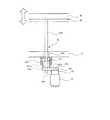
図17は、他の実施形態の三次元造形装置の駆動伝達部の構造を示す概略図である。 FIG. 17 is a schematic diagram illustrating a structure of a drive transmission unit of a three-dimensional modeling apparatus according to another embodiment.
図17に示す実施形態では、駆動部45の駆動力によってボールねじ43のねじ部432を回転させ、ナット部431を上下動させることで、可動フレーム411を上下動させ、ロッド412及びスライダ42を介して、テーブル41を上下動させる。なお、ロッド412とテーブル41を直接連結してもよい。 In the embodiment shown in FIG. 17, the
ナット部431は、内側にナット431aが収容され、外側のケース431bが可動フレーム411に一体に取り付けられる。ねじ部432は、上方で支持フレーム11に固定され、可動フレーム411を貫通し、可動フレーム411直下でナット431aと螺合し、下方でカップリングを介して減速器44に連結される。 The
駆動部45から発生された駆動力は、減速部44を介してねじ部432を回転させる。ねじ部432が回転すると、ナット部431のナット431aが回転する。ナット部431は、ねじ部432に沿って上下動可能なので、ナット431aが回転すると、可動フレーム411及びロッド412を介してスライダ42が上下動し、テーブル41が上下動する。 The driving force generated from the
図18は、他の実施形態の三次元造形装置の駆動伝達部の構造を示す概略図である。 FIG. 18 is a schematic diagram illustrating a structure of a drive transmission unit of a three-dimensional modeling apparatus according to another embodiment.
図18に示す実施形態では、駆動部45の駆動力によってナット部431のナット431aを回転させ、ボールねじ43のねじ部432を上下動させることで、スライダ42を介して、テーブル41を上下動させる。なお、ねじ部432とテーブル41を直接連結してもよい。 In the embodiment shown in FIG. 18, the
ナット部431は、内側にナット431aが収容され、基準フレーム12に固定されたナット支持部41bに外側のケース431bが固定され、上下動不能である。ナット431aは、ケース431bに対して回転可能である。ねじ部432は、上方でテーブル41に回転可能に固定され、下方でナット431aと螺合する。また、ねじ部432は、基準フレーム12に固定されるスプラインナット433を貫通する。 The
減速部44の出力軸44aには、第1プーリ401が固定される。ナット431aには、第2プーリ402が固定される。第1プーリ401と第2プーリ402は、連結ベルト401で連結される。第2プーリ402は、ナット部431のナット431aと共に回転し、ねじ部432を貫通させる。 A
駆動部45から発生された駆動力は、減速部44の出力軸44aを介して第1プーリ401に出力される。第1プーリ401が回転すると、連結ベルト401を介して第2プーリ402が回転する。第2プーリ402が回転すると、ナット部431のナット431aが回転する。ナット部431は、上下動不能なので、ナット431aが回転すると、ねじ部432が上下動する。したがって、テーブル41が上下動する。 The driving force generated from the
図19は、他の実施形態の三次元造形装置の駆動伝達部の構造を示す概略図である。 FIG. 19 is a schematic diagram illustrating a structure of a drive transmission unit of a three-dimensional modeling apparatus according to another embodiment.
図19に示す実施形態では、駆動部45の駆動力によってナット部431のナット431aを回転させ、ボールねじ43のナット部431をねじ部432に対して上下動させることで、可動フレーム411を上下動させ、ロッド412及びスライダ42を介して、テーブル41を上下動させる。なお、ロッド412とテーブル41を直接連結してもよい。 In the embodiment shown in FIG. 19, the
ナット部431は、内側にナット431aが収容され、可動フレーム411に固定されたナット支持部41bに外側のケース431bが固定され、可動フレーム411に一体に取り付けられる。また、駆動部45及び減速部44も可動フレーム411に一体に取り付けられ、可動フレーム411と共に上下動する。 The
ねじ部432は、上方で支持フレーム11に固定され、下方でナット431aと螺合する。また、ねじ部432は、可動フレーム411に固定されるスプラインナット433を貫通する。 The
減速部44の出力軸44aには、第1プーリ401が固定される。ナット431aには、第2プーリ402が固定される。第1プーリ401と第2プーリ402は、連結ベルト401で連結される。第2プーリ402は、ナット部431のナット431aと共に回転し、ねじ部432を貫通させる。 A
駆動部45から発生された駆動力は、減速部44の出力軸44aを介して第1プーリ401に出力される。第1プーリ401が回転すると、連結ベルト401を介して第2プーリ402が回転する。第2プーリ402が回転すると、ナット部431のナット431aが回転する。ナット431aが回転すると、ねじ部432が上下動不能なので、ナット431aが上下動する。したがって、ナット部431と共に可動フレーム411が上下動し、ロッド412で連結されたスライダ42及びテーブル41が上下動する。 The driving force generated from the
図20は、他の実施形態の三次元造形装置の駆動伝達部の構造を示す概略図である。 FIG. 20 is a schematic diagram illustrating a structure of a drive transmission unit of a three-dimensional modeling apparatus according to another embodiment.
図20に示す実施形態では、駆動部45として中空のダイレクトドライブモータを用いて、ナット431aを回転させ、ボールねじ43のねじ部432を上下動させることで、スライダ42を介して、テーブル41を上下動させる。なお、ねじ部432とテーブル41を直接連結してもよい。 In the embodiment shown in FIG. 20, a hollow direct drive motor is used as the
駆動部45は、中空のダイレクトドライブモータでナット431aを駆動させ、中心にねじ部432を貫通させる。 The
ナット部431は、内側にナット431aが収容され、基準フレーム12に対して上下動不能に固定される。ナット431aは、ケース431bに対して回転可能である。ねじ部432は、上方でテーブル41に回転可能に固定され、下方でナット431aと螺合する。 The
駆動部45が駆動力を発生させると、ナット部431のナット431aが回転する。ナット部431は、上下動不能なので、ナット431aが回転すると、ねじ部432が上下動する。したがって、テーブル41が上下動する。 When the driving
図21は、他の実施形態の三次元造形装置の駆動伝達部の構造を示す概略図である。 FIG. 21 is a schematic diagram illustrating a structure of a drive transmission unit of a three-dimensional modeling apparatus according to another embodiment.
図21に示す実施形態では、駆動部45として中空のダイレクトドライブモータを用いて、ナット431aを回転させ、ボールねじ43のねじ部432を上下動させることで、可動フレーム411を上下動させ、ロッド412及びスライダ42を介して、テーブル41を上下動させる。なお、ロッド412とテーブル41を直接連結してもよい。 In the embodiment shown in FIG. 21, a hollow direct drive motor is used as the
駆動部45は、中空のダイレクトドライブモータでナット431aを駆動させ、中心にねじ部432を貫通させる。 The
ナット部431は、内側にナット431aが収容され、外側のケース431bが可動フレーム411に対して固定される。ナット431aは、ケース431bに対して回転可能である。ねじ部432は、上方でフレーム11に固定され、下方でナット431aと螺合する。 The
駆動部45が駆動力を発生させると、ナット部431のナット431aが回転する。ナット部431は、ナット431aが回転すると、ねじ部432に沿ってナット431aが上下動する。したがって、ナット部431と共に可動フレーム411が上下動し、ロッド412で連結されたスライダ42及びテーブル41が上下動する。 When the driving
ここで、他の実施形態の三次元造形装置1の駆動伝達部の配置及び構造における制御システムは、図5で説明したものと同様でよい。 Here, the control system in the arrangement and structure of the drive transmission unit of the three-
本実施形態の三次元造形装置1によれば、支持フレーム11と、支持フレーム11に支持される材料供給部3と、支持フレーム11に支持され、材料供給部3から供給される材料が載置される造形物載置部4と、を備え、造形物載置部4は、上面に造形物が載置されるテーブル41と、テーブル41を駆動する駆動部45と、テーブル41の位置を測定する測定部46と、測定部46の測定値に基づいて、駆動部45を制御する制御部50と、を有するので、精度及び生産性の高い三次元造形装置を提供することが可能となる。 According to the three-
本実施形態の三次元造形装置1は、テーブル41の指示移動量をあらかじめ入力する入力部51と、入力部41から入力された指示移動量を記憶する記憶部52と、を備え、制御部50は、記憶部52に記憶した指示移動量の分だけテーブル41を移動させるので、的確に制御することが可能となる。 The three-
本実施形態の三次元造形装置1では、制御部50は、駆動部45の状態信号がフィードバックされるので、より高精度に制御することが可能となる。 In the three-
駆動部45は、独立して駆動可能な第1駆動部45a及び第2駆動部45bを有し、測定部46は、テーブル41の位置をそれぞれ測定する第1磁気センサ46a及び第2磁気センサ46bを有し、制御部50は、第1磁気センサ46a及び第2磁気センサ46bの各測定値に基づいて、第1駆動部45a及び第2駆動部45bをそれぞれ独立して制御するので、精度及び生産性の高い三次元造形装置を提供することが可能となる。 The
また、本実施形態の三次元造形装置1は、第1駆動部45a及び第2駆動部45bの各駆動力をスライダ42にそれぞれ伝達する第1ボールねじ43a及び第2ボールねじ43bを有する伝達部43をさらに備えるので、テーブル41を円滑に移動させることが可能となる。 Further, the three-
本実施形態の三次元造形装置1では、第1磁気センサ46a及び第2磁気センサ46bは、テーブル41と第1ボールねじ43a及び第2ボールねじ43bの支持位置に対応してそれぞれ配設されるので、より高精度に制御することが可能となる。 In the three-
本実施形態の三次元造形装置1では、駆動部45は、四角形を形成する位置に配置される第1駆動部45a、第2駆動部45b、第3駆動部45c、及び第4駆動部45dを有し、伝達部43は、第1駆動部45a、第2駆動部45b、第3駆動部45c、及び第4駆動部45dの駆動力をテーブル41に伝達する第1ボールネジ43a、第2ボールネジ43b、第3ボールネジ43c、及び第4ボールネジ43dを有し、制御部50は、第1駆動部45a、第2駆動部45b、第3駆動部45c、及び第4駆動部45dをそれぞれ独立して制御可能であるので、より高精度に制御することが可能となる。 In the three-
本実施形態の三次元造形装置1は、テーブル41と共に移動するロッド48と、ロッド48が所定の位置に到達した場合に接触するリミットスイッチ49と、を備えるので、テーブル41の過度な移動を防止することが可能となる。 The three-
なお、本発明は、この実施形態によって限定されるものではない。すなわち、実施形態の説明に当たって、例示のために特定の詳細な内容が多く含まれるが、これらの詳細な内容に色々なバリエーションや変更を加えてもよい。 The present invention is not limited to this embodiment. That is, in the description of the embodiment, many specific details are included for illustration, but various variations and modifications may be added to these details.
1…三次元造形装置
11…支持フレーム
12…基準フレーム(支持フレーム)
2…エネルギービーム照射部(材料供給部)
21…ビーム発生部
22…ビーム走査部
3…粉末供給部(材料供給部)
31…粉末貯留部
32…均し部
33…外枠部
4…造形物載置部
41…テーブル
42…スライダ
43…ボールねじ(伝達部)
44…減速部(伝達部)
45…駆動部
46…磁気センサ(測定部)
47…磁気スケール(測定部)
48…ロッド
49…リミットスイッチ
50…制御部
51…入力部
52…記憶部DESCRIPTION OF
2. Energy beam irradiation unit (material supply unit)
21 ...
DESCRIPTION OF
44 ... Deceleration part (transmission part)
45 ...
47 ... Magnetic scale (measurement part)
48 ...
Claims (7)
Translated fromJapanese前記支持フレームに支持される材料供給部と、
前記支持フレームに支持され、前記材料供給部から供給される材料が載置される1つの平面状のテーブルと、
前記テーブルを駆動する駆動部と、
前記テーブルの位置を測定する測定部と、
前記測定部の測定値に基づいて、前記駆動部を制御する制御部と、
を備え、
前記駆動部は、独立して駆動可能な第1駆動部及び第2駆動部を少なくとも有し、
前記測定部は、前記テーブルの位置をそれぞれ測定する第1測定部及び第2測定部を少なくとも有し、
前記制御部は、前記第1測定部及び前記第2測定部の各測定値に基づいて、前記第1駆動部及び前記第2駆動部をそれぞれ独立して制御する
ことを特徴とする三次元造形装置。A support frame;
A material supply unit supported by the support frame;
One planar table on which the material supported by the support frame and supplied from the material supply unit is placed;
A drive unit for driving the table;
A measuring unit for measuring the position of the table;
A control unit for controlling the drive unit based on the measurement value of the measurement unit;
With
The drive unit has at least a first drive unit and a second drive unit that can be driven independently,
The measurement unit has at least a first measurement unit and a second measurement unit for measuring the position of the table, respectively.
The control unit controls the first driving unit and the second driving unit independently based on measurement values of the first measurement unit and the second measurement unit, respectively. 3D modeling device.
前記入力部から入力された指示移動量を記憶する記憶部と、
を備え、
前記制御部は、前記記憶部に記憶した指示移動量の分だけ前記テーブルを移動させる
請求項1に記載の三次元造形装置。An input unit for inputting in advance an instruction movement amount of the table;
A storage unit that stores an instruction movement amount input from the input unit;
With
The three-dimensional modeling apparatus according to claim 1, wherein the control unit moves the table by an instruction movement amount stored in the storage unit.
請求項1又は2に記載の三次元造形装置。The three-dimensional modeling apparatus according to claim 1, wherein the control unit is fed back with a state signal of the driving unit.
請求項1乃至3のいずれか1つに記載の三次元造形装置。Toany one of claims1 to 3, further comprising a transmission unit having a first transmission section and a second transmission unit and transmits it first driverfront SL and the driving force of the second drive unit to the table The three-dimensional modeling apparatus described.
請求項4に記載の三次元造形装置。5. The three-dimensional modeling apparatus according to claim4 , wherein the first measurement unit and the second measurement unit are respectively arranged corresponding to support positions of the table, the first transmission unit, and the second transmission unit.
前記第1駆動部、前記第2駆動部、前記第3駆動部及び前記第4駆動部は、四角形を形成する位置に配置され、
前記伝達部は、前記第3駆動部及び前記第4駆動部の駆動力を前記テーブルに伝達する第3伝達部及び第4伝達部をさらに有し、
前記制御部は、前記第1駆動部、前記第2駆動部、前記第3駆動部、及び前記第4駆動部をそれぞれ独立して制御可能である
請求項5に記載の三次元造形装置。The driving unit further includes a third driving unit and a fourth driving unit that can be driven independently,
The first driving unit, the second driving unit, the third driving unit, and the fourth driving unit are arranged at positions that form a quadrangle,
The transmission unit further includes a third transmission unit and a fourth transmission unit that transmit the driving force of the third driving unit and the fourth driving unit to the table,
The three-dimensional modeling apparatus according to claim5 , wherein the control unit is capable of independently controlling the first drive unit, the second drive unit, the third drive unit, and the fourth drive unit.
前記ロッドが所定の位置に到達した場合に接触するリミットスイッチと、
を備える請求項1乃至6のいずれか1つに記載の三次元造形装置。A rod that moves with the table;
A limit switch that contacts when the rod reaches a predetermined position;
The three-dimensional modeling apparatus according to any one of claims 1 to6 .
Priority Applications (5)
| Application Number | Priority Date | Filing Date | Title |
|---|---|---|---|
| JP2014125077AJP6411784B2 (en) | 2014-01-14 | 2014-06-18 | 3D modeling equipment |
| PCT/JP2015/066352WO2015194398A1 (en) | 2014-06-18 | 2015-06-05 | 3d molding device |
| EP15810182.4AEP3159142A4 (en) | 2014-06-18 | 2015-06-05 | 3d molding device |
| US15/319,122US11407033B2 (en) | 2014-01-14 | 2015-06-05 | Three-dimensional shaping apparatus |
| CN201580032492.5ACN106457395A (en) | 2014-01-14 | 2015-06-05 | 3d molding device |
Applications Claiming Priority (3)
| Application Number | Priority Date | Filing Date | Title |
|---|---|---|---|
| JP2014003908 | 2014-01-14 | ||
| JP2014003908 | 2014-01-14 | ||
| JP2014125077AJP6411784B2 (en) | 2014-01-14 | 2014-06-18 | 3D modeling equipment |
Publications (2)
| Publication Number | Publication Date |
|---|---|
| JP2015155188A JP2015155188A (en) | 2015-08-27 |
| JP6411784B2true JP6411784B2 (en) | 2018-10-24 |
Family
ID=54774826
Family Applications (1)
| Application Number | Title | Priority Date | Filing Date |
|---|---|---|---|
| JP2014125077AActiveJP6411784B2 (en) | 2014-01-14 | 2014-06-18 | 3D modeling equipment |
Country Status (2)
| Country | Link |
|---|---|
| JP (1) | JP6411784B2 (en) |
| CN (1) | CN106457395A (en) |
Families Citing this family (7)
| Publication number | Priority date | Publication date | Assignee | Title |
|---|---|---|---|---|
| DE102016114056A1 (en) | 2016-07-29 | 2018-02-01 | Cl Schutzrechtsverwaltungs Gmbh | Powder module for a device for the additive production of three-dimensional objects |
| DE102016114053A1 (en) | 2016-07-29 | 2018-02-01 | Cl Schutzrechtsverwaltungs Gmbh | Powder module for a device for the additive production of three-dimensional objects |
| CN107421987B (en) | 2017-08-08 | 2023-04-21 | 河南理工大学 | A device and method for measuring the heating rate of low-temperature oxidation of coal |
| CN107262717B (en)* | 2017-08-08 | 2019-08-06 | 重庆大学 | Selective laser melting workbench for partition lifting into form |
| EP3446858A1 (en)* | 2017-08-25 | 2019-02-27 | CL Schutzrechtsverwaltungs GmbH | Apparatus for additively manufacturing of three-dimensional objects |
| DE102018128106A1 (en)* | 2018-11-09 | 2020-05-14 | GEWO Feinmechanik GmbH | 3D printer with an adjustable print bed and method for aligning a print bed of a 3D printer |
| US11872755B2 (en) | 2019-05-16 | 2024-01-16 | Canon Kabushiki Kaisha | Method for manufacturing product, and additive manufacturing apparatus |
Family Cites Families (13)
| Publication number | Priority date | Publication date | Assignee | Title |
|---|---|---|---|---|
| JP2749504B2 (en)* | 1993-12-29 | 1998-05-13 | 株式会社キラ・コーポレーション | Sheet additive manufacturing equipment |
| JP2000127252A (en)* | 1998-10-23 | 2000-05-09 | Sony Corp | Mold and its manufacturing method |
| JP2005297325A (en)* | 2004-04-09 | 2005-10-27 | Sony Corp | 3D modeling method and 3D model |
| JP4699051B2 (en)* | 2005-03-03 | 2011-06-08 | 三星ダイヤモンド工業株式会社 | Stereolithography equipment |
| US8206637B2 (en)* | 2008-10-14 | 2012-06-26 | The Boeing Company | Geometry adaptive laser sintering system |
| US8153183B2 (en)* | 2008-10-21 | 2012-04-10 | Stratasys, Inc. | Adjustable platform assembly for digital manufacturing system |
| DE102010006939A1 (en)* | 2010-02-04 | 2011-08-04 | Voxeljet Technology GmbH, 86167 | Device for producing three-dimensional models |
| CN102266942B (en)* | 2011-07-15 | 2013-06-05 | 华中科技大学 | Selective laser melting rapid forming device for directly manufacturing large-size parts |
| WO2013159811A1 (en)* | 2012-04-24 | 2013-10-31 | Arcam Ab | Safety protection method and apparatus for additive manufacturing device |
| US9993873B2 (en)* | 2012-05-22 | 2018-06-12 | General Electric Company | System and method for three-dimensional printing |
| DE102012014840A1 (en)* | 2012-07-27 | 2014-01-30 | Cl Schutzrechtsverwaltungs Gmbh | Device for producing three-dimensional objects by electromagnetic radiation or building material, comprises support device with a support for supporting object, coating device for applying building material layers and irradiation device |
| US9327350B2 (en)* | 2012-08-16 | 2016-05-03 | Stratasys, Inc. | Additive manufacturing technique for printing three-dimensional parts with printed receiving surfaces |
| JP2014104683A (en)* | 2012-11-29 | 2014-06-09 | Brother Ind Ltd | Three-dimensional contouring apparatus |
- 2014
- 2014-06-18JPJP2014125077Apatent/JP6411784B2/enactiveActive
- 2015
- 2015-06-05CNCN201580032492.5Apatent/CN106457395A/enactivePending
Also Published As
| Publication number | Publication date |
|---|---|
| JP2015155188A (en) | 2015-08-27 |
| CN106457395A (en) | 2017-02-22 |
Similar Documents
| Publication | Publication Date | Title |
|---|---|---|
| JP6411784B2 (en) | 3D modeling equipment | |
| WO2015194398A1 (en) | 3d molding device | |
| JP6411785B2 (en) | 3D modeling equipment | |
| US11407033B2 (en) | Three-dimensional shaping apparatus | |
| US8944802B2 (en) | Fixed printhead fused filament fabrication printer and method | |
| JP2021107150A (en) | Three-dimensional modeling method and device for objects with high resolution background | |
| JP7093770B2 (en) | Laminated modeling equipment | |
| CN110709195B (en) | Molding system and molding method | |
| CN104760424B (en) | Multifunctional assembled 3D printing device and multifunctional assembled 3D printing method | |
| KR20160109866A (en) | Apparatus and method for 3d printing | |
| CN107530972A (en) | Stereolithography machine with improved optical unit | |
| KR101798533B1 (en) | Molding apparatus and method by the 3d printer | |
| JP2018083966A (en) | Lamination molding apparatus | |
| CN106111985A (en) | Group scan laser selective sintering or curing and 3D forming machine thereof | |
| CN111093952A (en) | Measuring system for a device for the generative production of three-dimensional objects | |
| US11787107B2 (en) | Lifting system for device and a method for generatively manufacturing a three-dimensional object | |
| JP2019085640A (en) | Powder module | |
| CN111051045B (en) | Apparatus and method for producing large workpieces by moving production units | |
| CN107614161A (en) | Device for additive manufacturing of three-dimensional objects | |
| KR20160109099A (en) | Three-dimensional printing apparatus | |
| KR101817004B1 (en) | Auto-levelling system for dlp type 3d printer and dlp type 3d printer with same | |
| JP6477428B2 (en) | Control method of additive manufacturing apparatus | |
| KR20170002857A (en) | Temperature controlling method and apparatus for producing a three-dimensional object | |
| KR102199564B1 (en) | Device which is driven by six axes to manufacture a three-dimensional scaffold | |
| CN114102793A (en) | Ceramic material-increasing and material-decreasing composite manufacturing equipment |
Legal Events
| Date | Code | Title | Description |
|---|---|---|---|
| A621 | Written request for application examination | Free format text:JAPANESE INTERMEDIATE CODE: A621 Effective date:20170418 | |
| A131 | Notification of reasons for refusal | Free format text:JAPANESE INTERMEDIATE CODE: A131 Effective date:20180627 | |
| A521 | Request for written amendment filed | Free format text:JAPANESE INTERMEDIATE CODE: A523 Effective date:20180822 | |
| TRDD | Decision of grant or rejection written | ||
| A01 | Written decision to grant a patent or to grant a registration (utility model) | Free format text:JAPANESE INTERMEDIATE CODE: A01 Effective date:20180919 | |
| A61 | First payment of annual fees (during grant procedure) | Free format text:JAPANESE INTERMEDIATE CODE: A61 Effective date:20180927 | |
| R150 | Certificate of patent or registration of utility model | Ref document number:6411784 Country of ref document:JP Free format text:JAPANESE INTERMEDIATE CODE: R150 | |
| R250 | Receipt of annual fees | Free format text:JAPANESE INTERMEDIATE CODE: R250 | |
| R250 | Receipt of annual fees | Free format text:JAPANESE INTERMEDIATE CODE: R250 | |
| R250 | Receipt of annual fees | Free format text:JAPANESE INTERMEDIATE CODE: R250 | |
| R250 | Receipt of annual fees | Free format text:JAPANESE INTERMEDIATE CODE: R250 |