JP6410743B2 - Delivery device and delivery method - Google Patents
Delivery device and delivery methodDownload PDFInfo
- Publication number
- JP6410743B2 JP6410743B2JP2016014565AJP2016014565AJP6410743B2JP 6410743 B2JP6410743 B2JP 6410743B2JP 2016014565 AJP2016014565 AJP 2016014565AJP 2016014565 AJP2016014565 AJP 2016014565AJP 6410743 B2JP6410743 B2JP 6410743B2
- Authority
- JP
- Japan
- Prior art keywords
- delivery
- sleeve
- delivery device
- outer diameter
- outer sheath
- Prior art date
- Legal status (The legal status is an assumption and is not a legal conclusion. Google has not performed a legal analysis and makes no representation as to the accuracy of the status listed.)
- Active
Links
Images


Classifications
- A—HUMAN NECESSITIES
- A61—MEDICAL OR VETERINARY SCIENCE; HYGIENE
- A61F—FILTERS IMPLANTABLE INTO BLOOD VESSELS; PROSTHESES; DEVICES PROVIDING PATENCY TO, OR PREVENTING COLLAPSING OF, TUBULAR STRUCTURES OF THE BODY, e.g. STENTS; ORTHOPAEDIC, NURSING OR CONTRACEPTIVE DEVICES; FOMENTATION; TREATMENT OR PROTECTION OF EYES OR EARS; BANDAGES, DRESSINGS OR ABSORBENT PADS; FIRST-AID KITS
- A61F2/00—Filters implantable into blood vessels; Prostheses, i.e. artificial substitutes or replacements for parts of the body; Appliances for connecting them with the body; Devices providing patency to, or preventing collapsing of, tubular structures of the body, e.g. stents
- A61F2/95—Instruments specially adapted for placement or removal of stents or stent-grafts
- A61F2/962—Instruments specially adapted for placement or removal of stents or stent-grafts having an outer sleeve
- A61F2/966—Instruments specially adapted for placement or removal of stents or stent-grafts having an outer sleeve with relative longitudinal movement between outer sleeve and prosthesis, e.g. using a push rod
- A—HUMAN NECESSITIES
- A61—MEDICAL OR VETERINARY SCIENCE; HYGIENE
- A61F—FILTERS IMPLANTABLE INTO BLOOD VESSELS; PROSTHESES; DEVICES PROVIDING PATENCY TO, OR PREVENTING COLLAPSING OF, TUBULAR STRUCTURES OF THE BODY, e.g. STENTS; ORTHOPAEDIC, NURSING OR CONTRACEPTIVE DEVICES; FOMENTATION; TREATMENT OR PROTECTION OF EYES OR EARS; BANDAGES, DRESSINGS OR ABSORBENT PADS; FIRST-AID KITS
- A61F2/00—Filters implantable into blood vessels; Prostheses, i.e. artificial substitutes or replacements for parts of the body; Appliances for connecting them with the body; Devices providing patency to, or preventing collapsing of, tubular structures of the body, e.g. stents
- A61F2/82—Devices providing patency to, or preventing collapsing of, tubular structures of the body, e.g. stents
- A61F2/844—Devices providing patency to, or preventing collapsing of, tubular structures of the body, e.g. stents folded prior to deployment
- A—HUMAN NECESSITIES
- A61—MEDICAL OR VETERINARY SCIENCE; HYGIENE
- A61F—FILTERS IMPLANTABLE INTO BLOOD VESSELS; PROSTHESES; DEVICES PROVIDING PATENCY TO, OR PREVENTING COLLAPSING OF, TUBULAR STRUCTURES OF THE BODY, e.g. STENTS; ORTHOPAEDIC, NURSING OR CONTRACEPTIVE DEVICES; FOMENTATION; TREATMENT OR PROTECTION OF EYES OR EARS; BANDAGES, DRESSINGS OR ABSORBENT PADS; FIRST-AID KITS
- A61F2/00—Filters implantable into blood vessels; Prostheses, i.e. artificial substitutes or replacements for parts of the body; Appliances for connecting them with the body; Devices providing patency to, or preventing collapsing of, tubular structures of the body, e.g. stents
- A61F2/82—Devices providing patency to, or preventing collapsing of, tubular structures of the body, e.g. stents
- A61F2/86—Stents in a form characterised by the wire-like elements; Stents in the form characterised by a net-like or mesh-like structure
- A61F2/90—Stents in a form characterised by the wire-like elements; Stents in the form characterised by a net-like or mesh-like structure characterised by a net-like or mesh-like structure
- A61F2/91—Stents in a form characterised by the wire-like elements; Stents in the form characterised by a net-like or mesh-like structure characterised by a net-like or mesh-like structure made from perforated sheets or tubes, e.g. perforated by laser cuts or etched holes
- A61F2/915—Stents in a form characterised by the wire-like elements; Stents in the form characterised by a net-like or mesh-like structure characterised by a net-like or mesh-like structure made from perforated sheets or tubes, e.g. perforated by laser cuts or etched holes with bands having a meander structure, adjacent bands being connected to each other
- A—HUMAN NECESSITIES
- A61—MEDICAL OR VETERINARY SCIENCE; HYGIENE
- A61F—FILTERS IMPLANTABLE INTO BLOOD VESSELS; PROSTHESES; DEVICES PROVIDING PATENCY TO, OR PREVENTING COLLAPSING OF, TUBULAR STRUCTURES OF THE BODY, e.g. STENTS; ORTHOPAEDIC, NURSING OR CONTRACEPTIVE DEVICES; FOMENTATION; TREATMENT OR PROTECTION OF EYES OR EARS; BANDAGES, DRESSINGS OR ABSORBENT PADS; FIRST-AID KITS
- A61F2/00—Filters implantable into blood vessels; Prostheses, i.e. artificial substitutes or replacements for parts of the body; Appliances for connecting them with the body; Devices providing patency to, or preventing collapsing of, tubular structures of the body, e.g. stents
- A61F2/95—Instruments specially adapted for placement or removal of stents or stent-grafts
- A61F2/9517—Instruments specially adapted for placement or removal of stents or stent-grafts handle assemblies therefor
- A—HUMAN NECESSITIES
- A61—MEDICAL OR VETERINARY SCIENCE; HYGIENE
- A61F—FILTERS IMPLANTABLE INTO BLOOD VESSELS; PROSTHESES; DEVICES PROVIDING PATENCY TO, OR PREVENTING COLLAPSING OF, TUBULAR STRUCTURES OF THE BODY, e.g. STENTS; ORTHOPAEDIC, NURSING OR CONTRACEPTIVE DEVICES; FOMENTATION; TREATMENT OR PROTECTION OF EYES OR EARS; BANDAGES, DRESSINGS OR ABSORBENT PADS; FIRST-AID KITS
- A61F2/00—Filters implantable into blood vessels; Prostheses, i.e. artificial substitutes or replacements for parts of the body; Appliances for connecting them with the body; Devices providing patency to, or preventing collapsing of, tubular structures of the body, e.g. stents
- A61F2/82—Devices providing patency to, or preventing collapsing of, tubular structures of the body, e.g. stents
- A61F2002/826—Devices providing patency to, or preventing collapsing of, tubular structures of the body, e.g. stents more than one stent being applied sequentially
- A—HUMAN NECESSITIES
- A61—MEDICAL OR VETERINARY SCIENCE; HYGIENE
- A61F—FILTERS IMPLANTABLE INTO BLOOD VESSELS; PROSTHESES; DEVICES PROVIDING PATENCY TO, OR PREVENTING COLLAPSING OF, TUBULAR STRUCTURES OF THE BODY, e.g. STENTS; ORTHOPAEDIC, NURSING OR CONTRACEPTIVE DEVICES; FOMENTATION; TREATMENT OR PROTECTION OF EYES OR EARS; BANDAGES, DRESSINGS OR ABSORBENT PADS; FIRST-AID KITS
- A61F2/00—Filters implantable into blood vessels; Prostheses, i.e. artificial substitutes or replacements for parts of the body; Appliances for connecting them with the body; Devices providing patency to, or preventing collapsing of, tubular structures of the body, e.g. stents
- A61F2/82—Devices providing patency to, or preventing collapsing of, tubular structures of the body, e.g. stents
- A61F2/86—Stents in a form characterised by the wire-like elements; Stents in the form characterised by a net-like or mesh-like structure
- A61F2/90—Stents in a form characterised by the wire-like elements; Stents in the form characterised by a net-like or mesh-like structure characterised by a net-like or mesh-like structure
- A61F2/91—Stents in a form characterised by the wire-like elements; Stents in the form characterised by a net-like or mesh-like structure characterised by a net-like or mesh-like structure made from perforated sheets or tubes, e.g. perforated by laser cuts or etched holes
- A61F2/915—Stents in a form characterised by the wire-like elements; Stents in the form characterised by a net-like or mesh-like structure characterised by a net-like or mesh-like structure made from perforated sheets or tubes, e.g. perforated by laser cuts or etched holes with bands having a meander structure, adjacent bands being connected to each other
- A61F2002/9155—Adjacent bands being connected to each other
- A61F2002/91575—Adjacent bands being connected to each other connected peak to trough
- A—HUMAN NECESSITIES
- A61—MEDICAL OR VETERINARY SCIENCE; HYGIENE
- A61F—FILTERS IMPLANTABLE INTO BLOOD VESSELS; PROSTHESES; DEVICES PROVIDING PATENCY TO, OR PREVENTING COLLAPSING OF, TUBULAR STRUCTURES OF THE BODY, e.g. STENTS; ORTHOPAEDIC, NURSING OR CONTRACEPTIVE DEVICES; FOMENTATION; TREATMENT OR PROTECTION OF EYES OR EARS; BANDAGES, DRESSINGS OR ABSORBENT PADS; FIRST-AID KITS
- A61F2/00—Filters implantable into blood vessels; Prostheses, i.e. artificial substitutes or replacements for parts of the body; Appliances for connecting them with the body; Devices providing patency to, or preventing collapsing of, tubular structures of the body, e.g. stents
- A61F2/82—Devices providing patency to, or preventing collapsing of, tubular structures of the body, e.g. stents
- A61F2/86—Stents in a form characterised by the wire-like elements; Stents in the form characterised by a net-like or mesh-like structure
- A61F2/90—Stents in a form characterised by the wire-like elements; Stents in the form characterised by a net-like or mesh-like structure characterised by a net-like or mesh-like structure
- A61F2/91—Stents in a form characterised by the wire-like elements; Stents in the form characterised by a net-like or mesh-like structure characterised by a net-like or mesh-like structure made from perforated sheets or tubes, e.g. perforated by laser cuts or etched holes
- A61F2/915—Stents in a form characterised by the wire-like elements; Stents in the form characterised by a net-like or mesh-like structure characterised by a net-like or mesh-like structure made from perforated sheets or tubes, e.g. perforated by laser cuts or etched holes with bands having a meander structure, adjacent bands being connected to each other
- A61F2002/9155—Adjacent bands being connected to each other
- A61F2002/91583—Adjacent bands being connected to each other by a bridge, whereby at least one of its ends is connected along the length of a strut between two consecutive apices within a band
- A—HUMAN NECESSITIES
- A61—MEDICAL OR VETERINARY SCIENCE; HYGIENE
- A61F—FILTERS IMPLANTABLE INTO BLOOD VESSELS; PROSTHESES; DEVICES PROVIDING PATENCY TO, OR PREVENTING COLLAPSING OF, TUBULAR STRUCTURES OF THE BODY, e.g. STENTS; ORTHOPAEDIC, NURSING OR CONTRACEPTIVE DEVICES; FOMENTATION; TREATMENT OR PROTECTION OF EYES OR EARS; BANDAGES, DRESSINGS OR ABSORBENT PADS; FIRST-AID KITS
- A61F2/00—Filters implantable into blood vessels; Prostheses, i.e. artificial substitutes or replacements for parts of the body; Appliances for connecting them with the body; Devices providing patency to, or preventing collapsing of, tubular structures of the body, e.g. stents
- A61F2/95—Instruments specially adapted for placement or removal of stents or stent-grafts
- A61F2/962—Instruments specially adapted for placement or removal of stents or stent-grafts having an outer sleeve
- A61F2/966—Instruments specially adapted for placement or removal of stents or stent-grafts having an outer sleeve with relative longitudinal movement between outer sleeve and prosthesis, e.g. using a push rod
- A61F2002/9665—Instruments specially adapted for placement or removal of stents or stent-grafts having an outer sleeve with relative longitudinal movement between outer sleeve and prosthesis, e.g. using a push rod with additional retaining means
- A—HUMAN NECESSITIES
- A61—MEDICAL OR VETERINARY SCIENCE; HYGIENE
- A61F—FILTERS IMPLANTABLE INTO BLOOD VESSELS; PROSTHESES; DEVICES PROVIDING PATENCY TO, OR PREVENTING COLLAPSING OF, TUBULAR STRUCTURES OF THE BODY, e.g. STENTS; ORTHOPAEDIC, NURSING OR CONTRACEPTIVE DEVICES; FOMENTATION; TREATMENT OR PROTECTION OF EYES OR EARS; BANDAGES, DRESSINGS OR ABSORBENT PADS; FIRST-AID KITS
- A61F2250/00—Special features of prostheses classified in groups A61F2/00 - A61F2/26 or A61F2/82 or A61F9/00 or A61F11/00 or subgroups thereof
- A61F2250/0014—Special features of prostheses classified in groups A61F2/00 - A61F2/26 or A61F2/82 or A61F9/00 or A61F11/00 or subgroups thereof having different values of a given property or geometrical feature, e.g. mechanical property or material property, at different locations within the same prosthesis
- A61F2250/0019—Special features of prostheses classified in groups A61F2/00 - A61F2/26 or A61F2/82 or A61F9/00 or A61F11/00 or subgroups thereof having different values of a given property or geometrical feature, e.g. mechanical property or material property, at different locations within the same prosthesis differing in hardness, e.g. Vickers, Shore, Brinell
- A—HUMAN NECESSITIES
- A61—MEDICAL OR VETERINARY SCIENCE; HYGIENE
- A61F—FILTERS IMPLANTABLE INTO BLOOD VESSELS; PROSTHESES; DEVICES PROVIDING PATENCY TO, OR PREVENTING COLLAPSING OF, TUBULAR STRUCTURES OF THE BODY, e.g. STENTS; ORTHOPAEDIC, NURSING OR CONTRACEPTIVE DEVICES; FOMENTATION; TREATMENT OR PROTECTION OF EYES OR EARS; BANDAGES, DRESSINGS OR ABSORBENT PADS; FIRST-AID KITS
- A61F2250/00—Special features of prostheses classified in groups A61F2/00 - A61F2/26 or A61F2/82 or A61F9/00 or A61F11/00 or subgroups thereof
- A61F2250/0014—Special features of prostheses classified in groups A61F2/00 - A61F2/26 or A61F2/82 or A61F9/00 or A61F11/00 or subgroups thereof having different values of a given property or geometrical feature, e.g. mechanical property or material property, at different locations within the same prosthesis
- A61F2250/0039—Special features of prostheses classified in groups A61F2/00 - A61F2/26 or A61F2/82 or A61F9/00 or A61F11/00 or subgroups thereof having different values of a given property or geometrical feature, e.g. mechanical property or material property, at different locations within the same prosthesis differing in diameter
- A—HUMAN NECESSITIES
- A61—MEDICAL OR VETERINARY SCIENCE; HYGIENE
- A61F—FILTERS IMPLANTABLE INTO BLOOD VESSELS; PROSTHESES; DEVICES PROVIDING PATENCY TO, OR PREVENTING COLLAPSING OF, TUBULAR STRUCTURES OF THE BODY, e.g. STENTS; ORTHOPAEDIC, NURSING OR CONTRACEPTIVE DEVICES; FOMENTATION; TREATMENT OR PROTECTION OF EYES OR EARS; BANDAGES, DRESSINGS OR ABSORBENT PADS; FIRST-AID KITS
- A61F2250/00—Special features of prostheses classified in groups A61F2/00 - A61F2/26 or A61F2/82 or A61F9/00 or A61F11/00 or subgroups thereof
- A61F2250/0058—Additional features; Implant or prostheses properties not otherwise provided for
- A61F2250/0096—Markers and sensors for detecting a position or changes of a position of an implant, e.g. RF sensors, ultrasound markers
- A61F2250/0098—Markers and sensors for detecting a position or changes of a position of an implant, e.g. RF sensors, ultrasound markers radio-opaque, e.g. radio-opaque markers
Landscapes
- Health & Medical Sciences (AREA)
- Engineering & Computer Science (AREA)
- Biomedical Technology (AREA)
- Cardiology (AREA)
- Oral & Maxillofacial Surgery (AREA)
- Transplantation (AREA)
- Heart & Thoracic Surgery (AREA)
- Vascular Medicine (AREA)
- Life Sciences & Earth Sciences (AREA)
- Animal Behavior & Ethology (AREA)
- General Health & Medical Sciences (AREA)
- Public Health (AREA)
- Veterinary Medicine (AREA)
- Physics & Mathematics (AREA)
- Optics & Photonics (AREA)
- Media Introduction/Drainage Providing Device (AREA)
- Surgical Instruments (AREA)
Description
Translated fromJapanese送入装置および送入方法が、本明細書において開示される。特定の実施形態が、送入装置からの複数の腔内装置の順次送入に関して説明される。これらの送入装置および方法は、アテローム性動脈硬化閉塞疾患を治療するための処置において使用することが可能であるが、これらの処置に限られるわけではない。 A delivery device and delivery method are disclosed herein. Certain embodiments are described with respect to the sequential delivery of multiple intraluminal devices from the delivery device. These delivery devices and methods can be used in procedures for treating atherosclerotic obstruction disease, but are not limited to these procedures.
通路を生成または維持するためにステントなどの装置が体内に配置されるいくつかの医学的な状態および処置が存在する。膨張式の心臓、血管、および胆管用のステントから、腎臓と膀胱との間の尿の流れを可能にするために使用されるプラスチック製ステントまで、種々の目的に使用される幅広くさまざまなステントが存在する。 There are several medical conditions and procedures in which devices such as stents are placed in the body to create or maintain a passageway. There is a wide variety of stents used for a variety of purposes, from inflatable heart, blood vessel, and biliary stents to plastic stents used to allow urine flow between the kidney and bladder. Exists.
ステントは、多くの場合に、バルーン血管形成術などの医療処置の後に脈管系に配置される。バルーン血管形成術は、アテローム性動脈硬化閉塞疾患の治療に使用されることが多い。アテローム性動脈硬化閉塞疾患は、米国および工業化社会における脳卒中、心臓発作、四肢欠損、および死亡の主原因である。動脈硬化性プラークが、動脈の壁に沿って硬い層を形成し、カルシウム、コレステロール、密集した血栓、および細胞残屑で構成されうる。動脈硬化閉塞疾患が進行するにつれて、特定の血管を通過するように意図された血液の供給が、閉塞のプロセスによって減少し、場合によっては阻止される。臨床的に重大な動脈硬化性プラークについて最も広く利用される処置方法の1つは、バルーン血管形成術であり、その後にステントの配置を行うことができる。 Stents are often placed in the vasculature after medical procedures such as balloon angioplasty. Balloon angioplasty is often used to treat atherosclerotic obstruction disease. Atherosclerotic obstruction disease is a leading cause of stroke, heart attack, limb loss, and death in the United States and industrialized societies. Atherosclerotic plaque forms a hard layer along the wall of the artery and can be composed of calcium, cholesterol, dense thrombus, and cellular debris. As arteriosclerotic occlusion disease progresses, the blood supply that is intended to pass through specific blood vessels is reduced and possibly blocked by the process of occlusion. One of the most widely used treatment methods for clinically significant arteriosclerotic plaque is balloon angioplasty, which can be followed by stent placement.
現時点において利用可能なステントおよびステント送入システムは、多数の限界および欠点を抱えている。腔内装置および関連の送入装置における改善が、依然として必要とされている。 Currently available stents and stent delivery systems have a number of limitations and drawbacks. There is still a need for improvements in intraluminal devices and related delivery devices.
特定の実施形態によれば、複数の腔内装置(例えば、ステント、タック、ステイプル、など)の順次送入のための送入装置であって、複数の腔内装置を送入装置上に圧縮された状態で保持する送入装置を提供することができる。本明細書の目的において、用語「タック」が、送入装置から配置することができる多数の腔内装置のうちの1つを指すために使用される。送入装置は、複数の送入プラットフォームを備えることができ、各々の送入プラットフォームは、タックを圧縮された状態で送入装置上に保持するように構成され、非一定な外径、砂時計形状、テーパ状の近位側半分、畝(ridge)、くぼみ(dimple)、などの特有の形状を有する。この特有の形状を、放射線不透過性マーカであってもよい環状押しバンドの間に配置することができる。 According to certain embodiments, a delivery device for sequential delivery of multiple intraluminal devices (eg, stents, tacks, staples, etc.), wherein the multiple intraluminal devices are compressed onto the delivery device It is possible to provide an in-feed device that holds the device in a state in which it is held. For purposes herein, the term “tack” is used to refer to one of a number of intraluminal devices that can be deployed from a delivery device. The infeed device may comprise a plurality of infeed platforms, each infeed platform configured to hold the tack in a compressed state on the infeed device, a non-constant outer diameter, hourglass shape , Taper proximal half, ridge, dimple, etc. This unique shape can be placed between annular push bands, which can be radiopaque markers.
いくつかの実施形態において、特有の形状は、より硬い内側シャフトを囲むこの特有の形状を有する柔軟な材料のスリーブによってもたらされる。さらに、環状押しバンドを、放射線不透過性を保ちながら柔軟性を高めるために、ワイヤまたは素材の断片で作製することができる。 In some embodiments, the unique shape is provided by a sleeve of flexible material having this unique shape surrounding a stiffer inner shaft. In addition, the annular push band can be made of wire or a piece of material to increase flexibility while maintaining radiopacity.
タックの配置方法は、配置に先立つ外鞘および配置されるべきタックの放射線不透過性マーカの整列を含むことができる。 The tack placement method can include alignment of the outer sheath prior to placement and the radiopaque marker of the tack to be placed.
マーカバンドの整列ならびに腔内装置またはタックの送入の方法を、実行することができる。この方法は、圧縮された状態の複数のタックを有している送入装置を治療領域へと前進させるステップであって、各々のタックは、複数のストラット(strut)と、タックの中央領域に配置された放射線不透過性マーカとを備え、各々のタックは、同じサイズであって、放射線不透過性マーカが同じ位置に配置されており、送入装置は、複数のタックのうちの1つをそれぞれ有する複数の送入プラットフォームを有する内側コアと、内側コアおよび送入プラットフォームを覆う外鞘とを備え、外鞘は、遠位端から近位側に配置された放射線不透過性マーカバンドを有しているステップと、外鞘上の放射線不透過性マーカバンドと送入されるべき第1のタック上の放射線不透過性マーカとが整列するまで外鞘を引き戻すステップと、これら2つの放射線不透過性マーカを、タックを解放する前に、治療すべき組織の切開または病変などの治療領域に整列させるステップと、その後に外鞘を引き戻してタックを解放するステップと、を含むことができる。 The method of marker band alignment and delivery of intraluminal devices or tacks can be performed. The method includes advancing a delivery device having a plurality of compressed tacks to a treatment area, each tack having a plurality of struts and a central area of the tack. Each tack is the same size, the radiopaque markers are arranged at the same position, and the delivery device is one of the plurality of tacks. An inner core having a plurality of delivery platforms each having an inner core and an outer sheath covering the inner core and the delivery platform, wherein the outer sheath has a radiopaque marker band disposed proximally from the distal end. Pulling the outer sheath until the radiopaque marker band on the outer sheath and the radiopaque marker on the first tack to be delivered are aligned, and Aligning one radiopaque marker with a treatment area, such as an incision or lesion in the tissue to be treated, before releasing the tack, and then pulling back the outer sheath to release the tack. Can do.
いくつかの実施形態において、送入装置は、内側シャフトと、送入プラットフォームと、外鞘とを備えることができる。送入プラットフォームは、どちらも第1の外径を有している内側シャフトの周囲の1対の環状バンドと、スリーブとを含むことができる。スリーブを、内側シャフトへと固定し、環状バンドの間に位置させることができる。スリーブは、内側シャフトよりも小さいデュロメータ(durometer)を有することができ、さらに最適には、1対の環状バンドよりも小さいデュロメータを有することができる。スリーブは、環状バンドの第1の外径よりも小さい非一定な外径をさらに有することができる。送入プラットフォームを、送入装置から脈管内へと配置される腔内装置を受け入れておくように構成でき、環状バンドの間かつスリーブ上に腔内装置を受け入れるように構成することができる。外鞘は、内側シャフトおよび送入プラットフォーム上に配置されてよく、内側シャフトおよび送入プラットフォームを覆ってスライド可能であってよい。外鞘は、送入プラットフォームを覆う配置前位置と、外鞘が引き戻されて送入プラットフォームの環状バンドの少なくとも一方およびスリーブが露出される少なくとも1つの配置位置とを有する。 In some embodiments, the delivery device can include an inner shaft, a delivery platform, and an outer sheath. The delivery platform can include a pair of annular bands around the inner shaft, both having a first outer diameter, and a sleeve. A sleeve can be secured to the inner shaft and positioned between the annular bands. The sleeve can have a durometer that is smaller than the inner shaft, and more optimally can have a durometer that is smaller than a pair of annular bands. The sleeve may further have a non-constant outer diameter that is smaller than the first outer diameter of the annular band. The delivery platform can be configured to receive an intraluminal device that is placed from the delivery device into the vessel and can be configured to receive the intraluminal device between the annular band and on the sleeve. The outer sheath may be disposed on the inner shaft and the delivery platform and may be slidable over the inner shaft and the delivery platform. The outer sheath has a pre-deployment position that covers the delivery platform and at least one placement position where the outer sheath is pulled back to expose at least one of the annular bands and sleeve of the delivery platform.
いくつかの実施形態によれば、複数の追加の送入プラットフォームが、複数の腔内装置の順次送入のために含まれてよい。各々の追加の送入プラットフォームは、追加のスリーブおよび追加の環状バンドを備えることができる。環状バンドの各々は、近位端に半径を備えることができ、さらには/あるいは放射線不透過性らせんコイルを備えることができる。放射線不透過性らせんコイルは、スリーブを形成するポリマーよりも大きいデュロメータを有するポリマーに包まれてよい。 According to some embodiments, multiple additional delivery platforms may be included for the sequential delivery of multiple intraluminal devices. Each additional delivery platform can include an additional sleeve and an additional annular band. Each of the annular bands can include a radius at the proximal end and / or can include a radiopaque helical coil. The radiopaque helical coil may be encased in a polymer having a durometer that is larger than the polymer forming the sleeve.
スリーブは、任意の数の異なる形状およびサイズを含むことができ、畝、点、くぼみ、などを含むことができる。 The sleeve can include any number of different shapes and sizes, and can include folds, dots, indentations, and the like.
いくつかの実施形態において、送入装置は、ノーズコーン(nose cone)を遠位端に有する内側シャフトと、送入プラットフォームと、外鞘とを備えることができる。送入プラットフォームは、どちらも第1の外径を有しており、内側シャフトへと固定された1対の環状バンドと、内側シャフトへと固定され、環状バンドの間に位置するスリーブとを備えることができる。スリーブは、内側シャフトよりも小さいデュロメータを有することができ、さらに随意により1対の環状バンドよりも小さいデュロメータを有することができる。スリーブは、第1の一定な外径部分と、第1の一定な外径部分よりも大きいが、環状バンドの第1の外径よりは小さい外径を有する第2の一定な外径部分とをさらに有することができ、第2の一定な外径部分は、第1の一定な外径部分よりも軸方向の長さが短く、スリーブは、第1および第2の一定な外径部分の間の滑らかなテーパ状の推移をさらに有する。送入プラットフォームを、送入装置から脈管内へと配置される腔内装置を受け入れておくように構成でき、環状バンドの間かつスリーブ上に腔内装置を受け入れるように構成できる。外鞘を、内側シャフトおよび送入プラットフォーム上に配置でき、内側シャフトおよび送入プラットフォームを覆ってスライドさせることができる。外鞘は、送入プラットフォームを覆う配置前位置と、外鞘が引き戻されて送入プラットフォームの環状バンドの少なくとも一方およびスリーブが露出される少なくとも1つの配置位置とを有することができる。 In some embodiments, the delivery device can include an inner shaft having a nose cone at the distal end, a delivery platform, and an outer sheath. The delivery platform both has a first outer diameter and comprises a pair of annular bands secured to the inner shaft and a sleeve secured to the inner shaft and positioned between the annular bands. be able to. The sleeve can have a durometer that is smaller than the inner shaft, and optionally can have a durometer that is smaller than a pair of annular bands. The sleeve has a first constant outer diameter portion and a second constant outer diameter portion having an outer diameter that is larger than the first constant outer diameter portion but smaller than the first outer diameter of the annular band. And the second constant outer diameter portion has a shorter axial length than the first constant outer diameter portion, and the sleeve is formed of the first and second constant outer diameter portions. Further having a smooth taper transition in between. The delivery platform can be configured to receive an intraluminal device that is placed from the delivery device into the vessel and can be configured to receive the intraluminal device between the annular band and over the sleeve. The outer sheath can be placed on the inner shaft and the delivery platform and can be slid over the inner shaft and the delivery platform. The outer sheath can have a pre-deployment position that covers the delivery platform and at least one placement position where the outer sheath is pulled back to expose at least one of the annular bands of the delivery platform and the sleeve.
腔内装置の配置方法は、以下のステップのうちの1つ以上を含むことができる。圧縮された状態の複数の腔内装置を有している送入装置を、治療領域へと前進させるステップ。複数の腔内装置の各々は、複数のストラットと、腔内装置の中央領域に配置された放射線不透過性マーカとを備えることができる。複数の腔内装置の各々は、同じサイズであってよく、放射線不透過性マーカが同じ位置に配置されてよい。送入装置は、内側シャフトであって複数の送入プラットフォームを有しており、複数の腔内装置の各々の腔内装置が複数の送入プラットフォームのうちのそれぞれの送入プラットフォームに配置される内側シャフトと、内側シャフトおよび複数の送入プラットフォームを覆う外鞘とを備えることができ、外鞘は、外鞘の遠位端から近位側に配置される放射線不透過性マーカバンドを有する。外鞘上の放射線不透過性マーカバンドと、複数の腔内装置のうちの送入されるべき第1の腔内装置上の放射線不透過性マーカとが整列するまで、外鞘を引き戻すステップ。整列した放射線不透過性マーカバンドおよび放射線不透過性マーカを、第1の腔内装置の解放の前に、治療領域に整列させるステップ。外鞘を引き戻して第1の腔内装置を解放するステップ。外鞘上の放射線不透過性マーカバンドと、複数の腔内装置のうちの送入されるべき第2の腔内装置上の放射線不透過性マーカとが整列するまで、外鞘を引き戻すステップ。 The intraluminal device placement method can include one or more of the following steps. Advancing a delivery device having a plurality of compressed intraluminal devices to the treatment area; Each of the plurality of intraluminal devices can include a plurality of struts and a radiopaque marker disposed in a central region of the intraluminal device. Each of the plurality of intraluminal devices may be the same size and the radiopaque marker may be placed at the same location. The delivery device is an inner shaft and has a plurality of delivery platforms, and each intraluminal device of the plurality of intraluminal devices is disposed on a respective delivery platform of the plurality of delivery platforms. An inner shaft and an outer sheath covering the inner shaft and the plurality of delivery platforms can be provided, the outer sheath having a radiopaque marker band disposed proximally from the distal end of the outer sheath. Pulling back the outer sheath until the radiopaque marker band on the outer sheath and the radiopaque marker on the first intraluminal device to be delivered of the plurality of intraluminal devices are aligned. Aligning the aligned radiopaque marker band and radiopaque marker to the treatment area prior to release of the first intraluminal device. Retracting the outer sheath to release the first intraluminal device. Pulling back the outer sheath until the radiopaque marker band on the outer sheath and the radiopaque marker on the second intraluminal device to be delivered of the plurality of intraluminal devices are aligned.
本方法のいくつかの実施形態において、整列した放射線不透過性マーカバンドおよび放射線不透過性マーカを治療領域に整列させるステップは、整列した放射線不透過性マーカバンドおよび放射線不透過性マーカを、第1の腔内装置の解放の前に、組織の切開の中央に位置させるステップを含むことができる。本方法のいくつかの実施形態において、外鞘上の放射線不透過性マーカバンドと、複数の腔内装置のうちの送入されるべき第1の腔内装置上の放射線不透過性マーカとが整列するまで、外鞘を引き戻すステップは、外鞘の最も遠位側の端部と第1の腔内装置の最も遠位側の端部とが整列するまで外鞘を引き戻すステップを含むことができる。本方法のいくつかの実施形態において、外鞘上の放射線不透過性マーカバンドと、複数の腔内装置のうちの送入されるべき第1の腔内装置上の放射線不透過性マーカとが整列するまで、外鞘を引き戻すステップは、放射線不透過性マーカバンドが第1の腔内装置の中央に位置するまで外鞘を引き戻すステップを含むことができる。本方法のいくつかの実施形態において、第1の腔内装置は、放射線不透過性マーカのただ1つの列を有することができ、外鞘上の前記放射線不透過性マーカバンドと、複数の腔内装置のうちの送入されるべき第1の腔内装置上の放射線不透過性マーカとが整列するまで、外鞘を引き戻すステップは、放射線不透過性マーカバンドが放射線不透過性マーカのただ1つの列を取り囲むまで外鞘を引き戻すステップを含むことができる。 In some embodiments of the method, aligning the aligned radiopaque marker band and radiopaque marker to the treatment region comprises: aligning the aligned radiopaque marker band and radiopaque marker; Prior to the release of one intraluminal device, a step of centering the tissue incision may be included. In some embodiments of the method, a radiopaque marker band on the outer sheath and a radiopaque marker on the first intraluminal device to be delivered of the plurality of intraluminal devices. Pulling the outer sheath until aligned includes pulling the outer sheath back until the most distal end of the outer sheath and the most distal end of the first intraluminal device are aligned. it can. In some embodiments of the method, a radiopaque marker band on the outer sheath and a radiopaque marker on the first intraluminal device to be delivered of the plurality of intraluminal devices. Pulling the outer sheath back until aligned can include pulling the outer sheath back until the radiopaque marker band is centered in the first intraluminal device. In some embodiments of the method, the first intraluminal device can have a single row of radiopaque markers, the radiopaque marker band on the outer sheath, and a plurality of cavities. The step of retracting the outer sheath until the radiopaque marker on the first intraluminal device to be delivered of the inner device is aligned, the radiopaque marker band is just the radiopaque marker. Pulling back the outer sheath until it surrounds one row can be included.
種々の実施形態が、例示の目的で添付の図面に示されるが、決して本発明の技術的範囲を限定するものとして解釈されてはならない。ここで、類似の参照符号は、類似の実施形態にまたがって一貫して、対応する特徴を指し示している。 Various embodiments are shown in the accompanying drawings for purposes of illustration and should in no way be construed as limiting the scope of the invention. Here, like reference numerals refer to corresponding features consistently across like embodiments.
送入装置10を、アテローム性動脈硬化閉塞疾患を治療するための処置の一部として使用することができる。送入装置を、タックなどの1つ以上の腔内装置2を、プラーク蓄積の場所へともたらすために使用することができる。タックは、その場所を安定させ、さらには/あるいはプラーク片を、血流を妨げないように保持することができる。本明細書に記載の送入装置および方法は、主として脈管の処置に関して説明されるが、体の他の部分の治療にも使用可能であることを、理解できるであろう。 The
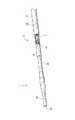
図1および2が、複数の腔内装置2の順次送入に使用することができる送入装置10の実施形態を示している。送入装置10は、アテローム性動脈硬化閉塞疾患を治療するための処置において使用することが可能であるが、これらの処置に限られるわけではない。 1 and 2 show an embodiment of a
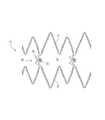
図示を容易にするために短くされている図1の送入装置10は、遠位端4および近位端6を強調している。近位端6を、医師または他の医療専門家が、医療処置の際に保持することができる。近位端6は、1つ以上の腔内装置またはタック2の送入を制御するために使用される。図2は、6つの腔内装置2を有する遠位端4を示しており、各々の腔内装置2は、専用の送入プラットフォーム8に配置されている。図1および2を比べると、図2においては外鞘12が遠位端から引き戻されていることを見て取ることができる。これにより、送入プラットフォーム8およびそれぞれの腔内装置2が露出している。腔内装置2は、好ましくは自己膨張型(self−expandable)であり、どのように送入プラットフォームに収まるのかを示すために、圧縮された状態で図示されている。典型的な使用において、外鞘12が、この状態にあるときの腔内装置2を覆う。さらに詳しく後述されるように、外鞘12を、一度に1つの腔内装置2を所望の治療場所に配置するために、系統だったやり方で引き戻すことができる。 The
例えばセル(cell)の列がただ1つ(図3および3A)または2つである比較的小さい腔内装置2を、正確な治療場所に送入し、重なり合うことがないように適度に離すことができる。図3Aが、図3のタックの平たくされた一部分を示している。セル14の1つの列が、波形のストラット16からなる2つの同心リングをブリッジ部材18によって接続することによって形成されていることを、見て取ることができる。ブリッジ部材18は、1対のアンカ20と、放射線不透過性マーカ22とを有している。複数の小さな腔内装置2を、1つまたは複数の損傷の治療に使用することができる。これは、体内の異物の量を最小限にしつつ、必要とされる保持力をもたらすことができる。腔内装置および送入装置の種々の実施形態が、本出願の出願人の関連の特許出願、すなわち2011年7月8日に出願され、米国特許出願公開第2012/0035705号として公開された特許出願第13/179,458号(IVAS.002P4)、および2013年1月24日に出願され、米国特許出願公開第2013/0144375号として公開された特許出願第13/749,643号(IVAS.002P6)にさらに詳しく記載されており、これらの特許出願はどちらも、ここでの言及によって本明細書に援用され、本明細書の一部を構成する。 For example, a relatively small
送入装置および方法が、より大型の装置などの他の腔内装置2にも使用可能であり、セルの列がただ1つまたは2つの腔内装置2における使用に限られないことを、理解できるであろう。 It will be appreciated that the delivery device and method can be used with other
次に図1に戻り、図示の実施形態の近位端6を、ここで説明する。送入装置10は、外鞘12と、近位側ハウジング24と、内側シャフト26とを備えることができる。外鞘12を、ポリマー押し出し材およびポリマー押し出し材に埋め込まれた編組線の積層品として作製することができる。柔軟性および剛性を、編組線の数、編組のパターン、および編組のピッチによって制御することができる。他の実施形態においては、外鞘を、金属製またはプラスチック製のハイポチューブ(hypotube)などのハイポチューブで形成することができる。鞘の柔軟性および剛性を、ハイポチューブの全長にわたるらせん状の切れ目の傾きおよび頻度などの多数の特徴によって制御することができる。さらに、外鞘は、遠位端またはその付近に放射線不透過性(RO)マーカ28を備えることができる。いくつかの実施形態において、放射線不透過性マーカ28は、最も遠位側の端部から間隔を空けて位置する環状の帯であってよい。 Returning now to FIG. 1, the
図示のとおり、外鞘12は、編組シャフトであり、近位側ハウジング24は、張力緩和部30を介して外鞘へとつながる二股ルアー(luer)である。張力緩和部30は、ポリオレフィンまたは他の同様の材料で作られるなど、任意の形態を取ることができる。 As shown, the
二股ルアー24は、内側シャフト26を受け入れる主アームと、横アームとを有する。二股ルアーを、外鞘の近位端に配置することができる。横アームは、空気を追い出し、鞘と内側シャフトとの間の空間の潤滑性を向上させるために使用されるフラッシングポートを備えている。 The
テューイボルスト(tuohy borst)アダプタ、止血弁、または他のシール機構32を、内側シャフト26と外鞘12との間の空間の近位端を受け入れて封止するために、二股ルアー24の近位側に設け、あるいは二股ルアー24に統合することができる。テューイボルストアダプタは、外鞘と内側シャフトとの間の関係を固定するためのねじ式ロックなどの係止のインターフェイスをもたらすこともできる。これは、医師がタックを時期尚早に配置してしまうことなく遠位端を適切に位置させることを、可能にすることができる。 The proximal side of the
内側シャフトは、近位側ルアーハブ34および配置基準マーク36を備えて図示されている。配置基準マーク36は、各々の配置基準マークの間の間隔が送入プラットフォームの特徴の間の間隔と同じであってよいように、送入プラットフォーム8に対応することができる。例えば、配置基準マークの間の間隔は、送入プラットフォームの中心間の距離と同じであってよい。 The inner shaft is shown with a
いくつかの実施形態においては、最も遠位側の配置基準マーク、あるいは太い帯または異なる色を有するなどの他とは異なるマークが、主位置またはホーム位置を示すことができる。例えば、帯の幅が他よりも広い配置基準マークを、二股ルアー24の近位端または止血弁32に整列させることができる。これは、外鞘がノーズコーン38の近位側の内側シャフト26を完全に覆う位置にあることを、医師に知らせることができる。いくつかの実施形態においては、この整列を、外鞘のROマーカ28の、内側シャフト26の遠位端のROマーカへの整列と解釈することもできる。 In some embodiments, the most distal placement reference mark, or a different mark such as having a thick band or a different color, can indicate the main or home position. For example, a placement reference mark having a wider band than others can be aligned with the proximal end of the
いくつかの実施形態においては、配置基準マーク36のうちの1つ以上が、システム内のタックの数を表すことができる。すなわち、ひとたびタックが解放されると、配置基準マーク36が覆い隠され、医師は、残りの配置基準マークが、使用することができる残りのタックの数に相当することを、知ることができる。そのような実施形態においては、二股ルアー24または止血弁32の近位端を、配置を示すために2つの基準マークの間のほぼ真ん中へと進めることができる。 In some embodiments, one or more of the placement fiducial marks 36 can represent the number of tacks in the system. That is, once the tack is released, the placement
次に図4を眺めると、送入装置10の遠位端4の詳細図が示されている。図示の実施形態の特徴として、遠位側の柔らかい先端38を有する内側シャフト26が挙げられる。先端38は、テーパ状のノーズコーンであってよい。ノーズコーン38は、組織を傷つけることなく押しのけ、脈管構造を通過する送入装置の案内を助けるための拡張構造として機能する。先端38自身が放射線不透過性であってよく、あるいは放射線不透過性の要素27を、先端またはその付近に取り入れることができる。内側シャフト26を通って近位側ルアーハブ34(図1)まで延びるガイドワイヤ管腔40を見て取ることができる。ガイドワイヤ管腔40は、ガイドワイヤを受け入れて前進させるように構成される。 Turning now to FIG. 4, a detailed view of the distal end 4 of the
送入プラットフォーム8の各部も示されている。送入プラットフォーム8は、図示の実施形態においては同一であるが、他の実施形態においては、異なる送入プラットフォームの間でサイズおよび構成が違ってもよい。縮められ(crimped)、あるいは圧縮されたタック2が、送入プラットフォーム8に示されている。 The parts of the delivery platform 8 are also shown. The delivery platform 8 is the same in the illustrated embodiment, but in other embodiments, the size and configuration may differ between different delivery platforms. A crimped or compressed
図2および4に見て取ることができるとおり、1つ以上の送入プラットフォーム8を、送入装置10の遠位端4の付近において内側シャフト26上に配置することができる。送入プラットフォーム8の各々は、1対の環状押しバンド44の間に位置して広がる凹所42を備えることができる。図5が、送入プラットフォーム8Aの一実施形態における送入装置の断面を示している。図示の実施形態において、第1のプラットフォーム8Aの近位側の環状押しバンド44Aは、すぐ近位側に位置するプラットフォーム8B(一部分だけが図示されている)の遠位側の環状押しバンド44Aでもある。環状押しバンド44は、凹所42における送入プラットフォームと比べて、より大きな外径を有している。いくつかの実施形態においては、凹所を、1つまたは2つの環状押しバンドならびに/あるいは内側シャフト26上のさらなる特徴に隣接し、あるいはこれらの間に位置する小径の領域として定めることができる。 As can be seen in FIGS. 2 and 4, one or more delivery platforms 8 can be disposed on the
環状押しバンド44のうちの1つ以上は、放射線不透過性マーカバンドであってよい。例えば、近位側および遠位側放射線不透過性マーカバンド44を、プラットフォーム8の端部を標準的な視覚化技術を使用して視認できるようにするために設けることができる。環状マーカバンド44は、例えばタンタル、イリジウム、および白金材料のうちの1つ以上を含むなど、任意の適切な形態をとることができる。いくつかの実施形態において、押しバンド44は、4mmの長さであってよく、間に6.75mmの凹所を備えることができる。6.5mmのタックを、押しバンド44の間に配置することができる。いくつかの実施形態において、押しバンドは、凹所および/またはタックのサイズの50〜70%の間であってよい。いくつかの実施形態において、押しバンドは、約60%である。他の実施形態において、押しバンドは、はるかに小さくてよく、凹所および/またはタックのサイズの10〜20%の間であってよい。これは、とくには、より長いタックに当てはまるかもしれない。いくつかの実施形態において、押しバンド44の少なくとも近位端は、送入装置を引き戻す際に配置済みのタックに引っ掛かる可能性を減らす役に立つような半径を有することができる。 One or more of the
凹所とタックとの間の長さの差を小さくすることで、とりわけセルの列が1つまたは2つだけであるタックにおいて、タックの配置の精度を高めることができる。いくつかの実施形態において、凹所とタックとの間の長さの差は、1、0.5、0.4、0.3、0.25、または0.2mm未満であってよい。タックは、長さ4、5、6、6.5、8、10、または12mmなど、任意の数の異なるサイズであってよい。 By reducing the difference in length between the recess and the tack, it is possible to increase the accuracy of the tack arrangement, particularly in a tack having only one or two rows of cells. In some embodiments, the difference in length between the recess and the tack may be less than 1, 0.5, 0.4, 0.3, 0.25, or 0.2 mm. The tack may be any number of different sizes, such as 4, 5, 6, 6.5, 8, 10, or 12 mm in length.
外鞘12を、PEBAXという商品名で入手可能なポリエーテルブロックアミド(PEBA)、すなわち熱可塑性エラストマ(TPE)で作製することができる。いくつかの実施形態において、外鞘12は、TEFLONなどのポリテトラフルオロエチレン(PTFE)で作られた薄い内側ライナを有することができる。任意の放射線不透過性マーカバンド28または他の放射線不透過性材料を、これら2つの層の間に配置することができる。他の実施形態においては、放射線不透過性マーカバンド28または他の放射線不透過性材料を、外鞘12の1つ以上の層に埋め込むことができる。放射線不透過性マーカバンド28は、幅が0.5mm〜5mmの範囲であってよく、最も遠位側の先端52から近位側0.5mm〜10mmに位置することができる。いくつかの実施形態において、放射線不透過性マーカバンド28は、幅1mmであってよく、最も遠位側の先端52から近位側3mmに位置することができる。 The
図5の断面において、スリーブ46が2つの環状バンド44の間の内側シャフト26の周囲に位置することを、見て取ることができる。いくつかの実施形態において、送入プラットフォーム8は、シャフト26を囲むスリーブ46を備えることができ、ここでスリーブ46は、シャフト26とは異なる材料で作られ、あるいはシャフト26とは異なる材料特性を有する。いくつかの実施形態において、スリーブは、タックを送入プラットフォームの所定の場所にとどまらせる役に立つ粘着性、グリップ、表面の模様、および/または他の特徴を有する材料を提供する。いくつかの実施形態においては、スリーブを、PEBAで作製することができる。いくつかの実施形態による内側シャフトは、PTFE/ポリイミド複合材料で作製された複合押し出し材である。スリーブは、内側シャフトおよび/または押しバンド44よりも柔らかくて(デュロメータが小さくて)よい。これは、類似の種類の材料で作製される場合にも当てはまりうる。いくつかの実施形態において、スリーブは、外鞘12を引き戻すときにタックを所定の場所(例えば、内側シャフトに対する長手方向の位置)にとどまらせる役に立つ粘着性、グリップ、表面の模様、および/または他の特徴を有する材料であってよい。これは、配置の際の制御性を高めることができ、タックが送入プラットフォームから遠位側へと撃ち出される可能性(業界においてウォーターメロンシーディング(watermelon seeding)として知られている)を減らすことができる。いくつかの場合には、外鞘を途中まで取り去ることによって腔内装置を部分的に露出させることができることで、腔内装置を、完全な解放まで送入装置によって確実に保持しつつ、或る程度まで膨張させることができる。 In the cross section of FIG. 5 it can be seen that the
スリーブ46を、タック2が送入プラットフォーム8に位置した状態においてタックと外鞘との間の空間が最小限または皆無であるようなサイズとすることができる。いくつかの実施形態においては、スリーブ46を、内側シャフト26と一緒に成形でき、あるいは内側シャフト26上へと押し出すことができる。いくつかの実施形態においては、送入装置10を、内側シャフト26の或る長さについて延びるただ1つのスリーブ46を備えて形成することができる。例えば、スリーブは、最初の送入プラットフォームから最後の送入プラットフォームまで延びることができる。環状バンド44が、スリーブ46の別々の部分を囲むことができ、あるいはスリーブ46によって包まれてよい。いくつかの実施形態においては、各々の送入プラットフォーム8が、凹所42に位置する別々のスリーブ46を有する。環状バンド44は、異なる材料によって包まれてよく、あるいはまったく包まれなくてもよい。 The
図5から理解されるとおり、スリーブ46は、スリーブの一部分または全長にわたって保たれる円形の断面を有する円筒形であってよい。他の実施形態において、スリーブは、特有の形状を有することができ、テーパ(図6A〜6E)、砂時計形状(図6A)、畝(図6B)、くぼみ(図6C)、点(dot)(図6D)、2つ以上の異なる直径(図6E)、などのうちの1つ以上を含むことができる。畝、点、およびくぼみなどの特徴を、いくつかの異なる模様またはグループにて配置することができる。さらに、スリーブ(図6B〜D)またはスリーブ(図6E)の一部は、凹所全体にわたって延びる必要はない。いくつかの実施形態においては、スリーブまたは外径の大きい部分の長さが、タックの長さに対応することができる。例えば、スリーブまたは外径の大きい部分が、凹所および/またはタックの3/4、2/3、1/2、2/5、1/3、1/4を延びることができる。さらに、スリーブまたは外径の大きい部分の長さは、最も近位側の波形のリングなど、波形のリング16におけるストラットのサイズに関係でき、例えばストラットの長さまたは最も近位側の波形のリングの長さの全体、4/5、3/4、2/3、または1/2について延びることができる。短いスリーブ、またはスリーブの外径の大きい部分は、好ましくは凹所の近位端から遠位側へと延びる(図6D〜6E)が、凹所の中央に位置しても、遠位端に置かれても(図6C)、凹所内の他の位置に置かれてもよい。 As can be seen from FIG. 5, the
図6Eのスリーブは、間に短いテーパを有する2つの異なる一定の外径の部分を有して図示されている。スリーブを、熱によって接合される2つの別々の部分から形成することができる。テーパ部も、2つの一定の外径の部分の間に滑らかな推移が存在するように熱による結合によって生み出されてよい。すでに述べたように、より大きい一定の外径の部分は、好ましくは凹所の近位端から遠位側へと延びる。このより大きな外径の部分は、一定の外径を有していても、有していなくてもよいが、上述したように、凹所の全体にわたって延びる必要はない。 The sleeve of FIG. 6E is illustrated having two different constant outer diameter portions with a short taper therebetween. The sleeve can be formed from two separate parts that are joined together by heat. The taper may also be created by thermal coupling so that there is a smooth transition between the two constant outer diameter portions. As already mentioned, the larger constant outer diameter portion preferably extends distally from the proximal end of the recess. This larger outer diameter portion may or may not have a constant outer diameter, but does not need to extend throughout the recess, as described above.
いくつかの実施形態において、内側シャフト26は、押し部44の間により小さいデュロメータのスリーブ46を有することができる。タック2を、スリーブ46へと縮めることができ、外鞘12が、縮められたタックをその場に拘束することができる。スリーブ46と外鞘12との間のすき間が、縮められたタック2と内側および外側の要素との間にわずかな干渉を伴うはまり合いをもたらすことができる。このわずかな干渉は、タックがほぼ完全に鞘から露出して、タックの遠位部が「花びら」状に開いて脈管の壁に係合できるまで、送入システムが配置の際に縮められたタックを拘束することを可能にし、飛び出し(jumping)の可能性を減らすことができる。 In some embodiments, the
いくつかの実施形態によれば、内側シャフト26を、ポリイミド−PEBAの組み合わせで作製することができ、より小さいデュロメータのPEBAスリーブ46を、押し部44の間に熱によって接合することができる。タック2を、スリーブ46へと縮めることができ、PTFEで内側が覆われた外鞘12が、縮められたタックをその場に拘束することができる。 According to some embodiments, the
図5に戻ると、放射線不透過性マーカバンド44の特定の実施形態の特徴が示されている。すでに述べたように、スリーブ46は、環状バンド44を包むことができる。あるいは、別の材料が金属製のバンドを包み、環状のマーカバンド44を形成することができる。環状のマーカバンド44は、放射線不透過性を維持しながら柔軟性を増すために、ワイヤ48または複数の材料片で作られてよく、あるいはスリットを有することができる。いくつかの実施形態においては、ワイヤが、内側シャフト26の周囲に巻き付けられたらせんコイルを形成することができる。 Returning to FIG. 5, the features of a particular embodiment of the
次に図7A〜Cに移動し、配置の特定の方法を説明する。送入装置10を、アテローム性動脈硬化閉塞疾患を治療するための処置の一部として使用することができる。送入装置を、タックなどの1つ以上の腔内装置2を、プラーク蓄積の場所へともたらすために使用することができる。タックは、その場所を安定させ、さらには/あるいはプラーク片を、血流を妨げないように保持することができる。 Now moving to FIGS. 7A-C, a specific method of placement will be described. The
タックは、好ましくは自己膨張型である。したがって、鞘12を引き戻してタック2を露出させることで、タックを送入装置10から自己膨張によって配置することができる。鞘を、タックを血管内の所望の場所に順々にもたらすために、小さな増分にて引き戻すことができる。いくつかの実施形態において、小さな増分は、配置基準マーク36に対応することができる。配置基準マーク36は、より長いステントにおいて典型的な漸進的な解放よりもむしろ各々のタックを速やかに配置できるよう、少なくともタックの長さの間隔を有することができる。これは、タックのより正確な配置を可能にすることができる。 The tack is preferably self-expanding. Therefore, by pulling back the
バルーン血管形成術が、体内のあらゆる血管床において閉塞または狭隘化した血管を開く一般に受け入れられた方法である。バルーン血管形成術は、バルーン血管形成カテーテルによって実行される。バルーン血管形成カテーテルは、カテーテルへと取り付けられた葉巻(cigar)状の円柱形のバルーンで構成される。バルーン血管形成カテーテルは、経皮的に生成され、あるいは動脈の開放暴露によって生成される遠方のアクセス場所から動脈内に配置される。カテーテルは、カテーテルの進行を案内するワイヤ上で血管の内側に沿って通される。カテーテルのバルーンが取り付けられた部位が、治療を必要とするアテローム性動脈硬化プラークの場所に配置される。バルーンは、閉塞疾患の発現の前の動脈の元の直径に一致するサイズへと膨張させられる。いくつかの事例では、バルーンが、薬物または生物学的製剤で被覆され、あるいは他のやり方で薬物または生物学的製剤を組織へともたらすように構成される。バルーンが膨張させられるとき、プラークが割れる。へき開面がプラーク内に形成され、プラークの直径がバルーンの膨張につれて広がることを可能にする。多くの場合、プラークの一部分が、プラークの残りの部分よりも膨張に強く抵抗する。これが生じるとき、より大きな圧力をバルーンへと送り込むことで、バルーンの意図されるサイズへの完全な膨張がもたらされる。バルーンは、収縮させられて取り除かれ、動脈部分が再び検査される。バルーン血管形成術のプロセスは、制御できないプラーク破壊のプロセスである。治療の場所の血管の管腔は、通常は多少大きくなるが、常にではなく、確実にでもない。 Balloon angioplasty is a generally accepted method of opening obstructed or narrowed blood vessels in any vascular bed in the body. Balloon angioplasty is performed with a balloon angioplasty catheter. Balloon angioplasty catheters are comprised of cigar-shaped cylindrical balloons attached to the catheter. Balloon angioplasty catheters are created percutaneously or placed into an artery from a remote access location created by open exposure of the artery. The catheter is passed along the inside of the blood vessel over a wire that guides the progression of the catheter. The site where the catheter balloon is attached is placed at the location of the atherosclerotic plaque in need of treatment. The balloon is inflated to a size that matches the original diameter of the artery prior to the onset of occlusive disease. In some cases, the balloon is coated with a drug or biological product or otherwise configured to bring the drug or biological product to the tissue. When the balloon is inflated, the plaque breaks. A cleavage surface is formed in the plaque, allowing the diameter of the plaque to expand as the balloon is inflated. In many cases, a portion of the plaque resists swelling more strongly than the rest of the plaque. When this occurs, sending more pressure into the balloon results in full inflation to the intended size of the balloon. The balloon is deflated and removed, and the arterial portion is examined again. The process of balloon angioplasty is an uncontrollable process of plaque destruction. The lumen of the blood vessel at the treatment site is usually somewhat larger, but not always, but certainly not.
バルーン血管形成術におけるプラークの割れによって生じるへき開面の一部が、切開(dissection)を形成する可能性がある。より一般的には、切開は、プラークまたは組織の一部が動脈から離れて持ち上げられ、動脈に充分には付着しておらず、移動または遊離しうる場合に生じる。切開によって引き裂かれたプラークまたは組織が、流れへと突出する。プラークまたは組織が完全に血流の方向に持ち上がると、流れを妨げ、血管の急性の閉塞を引き起こす可能性がある。バルーン血管形成術の後の切開を、閉塞を防止し、残存狭窄を解消するように処置しなければならないことは、明らかである。また、いくつかの状況において、血管形成術の後に動脈を開いた状態に保ち、さらには/あるいは切開された物質を再び血管の壁へと押し付けて、血流にとって適切な管腔を生み出すために、ステントまたは他の腔内装置などの金属製の保持構造を配置することが有益であることも、明らかである。 A portion of the cleavage plane caused by plaque cracking in balloon angioplasty can form a incision. More generally, an incision occurs when a plaque or piece of tissue is lifted away from an artery and does not adhere well to the artery and can move or release. Plaque or tissue that has been torn by the incision protrudes into the flow. When plaque or tissue lifts completely in the direction of blood flow, it can impede flow and cause acute occlusion of blood vessels. It is clear that the incision after balloon angioplasty must be treated to prevent occlusion and eliminate residual stenosis. Also, in some situations, to keep the artery open after angioplasty and / or to force the dissected material back onto the vessel wall to create a suitable lumen for blood flow It is also clear that it may be beneficial to place a metal retaining structure such as a stent or other intraluminal device.
さまざまな送入方法および装置を、タック2などの腔内装置の配置に使用することができ、その一部が後述される。例えば、タックを、血管内挿入によって血管内へと送入すことができる。プラーク用タックの異なる実施形態のための送入装置は、違っていても、あるいは同じでもよく、特定のタックを送入するように特定的に設計された特徴を有することができる。タックおよび設置手順を、タックを血管内の位置へと移動させ、次いで血管内で膨張した状態へと解放することを可能にするために、送入機構(バルーンの膨張など)の膨張力および/または波形のリングの膨張力を利用するという共通の方法を共有するいくつかのやり方にて設計することができる。タックの配置方法は、配置に先立つ外鞘の放射線不透過性マーカおよび配置されるべきタックの整列を含むことができる。 Various delivery methods and devices can be used for placement of intraluminal devices, such as
次に図7Aを参照すると、外鞘12を備える送入装置10が、第1の配置前状態にて示されている。複数のタック2を、外鞘12によって送入装置10内に圧縮された状態で保持することができる。いくつかの実施形態において、タック2は、送入装置への搭載を容易にするために圧縮された状態へと急速冷凍される。タックは、すでに述べたように、送入装置の所与の長さについて延びることができる。 Referring now to FIG. 7A, the
送入装置を、患者の脈管系内でガイドワイヤ50を覆うようにして治療場所へと前進させることができる。ガイドワイヤ50は、血管形成術のバルーンを配置するために使用されるガイドワイヤなど、先行の処置段階において用いられた同じガイドワイヤであってよい。ひとたび治療の場所に配置されると、外鞘12を、第2の配置前位置(図7B)へと引き戻し、あるいは引っ込めることができる。第2の配置前位置を、タックの解放前に何らかの調節を必要とする可能性がある伸び、曲折、などを補償すべく、外鞘の位置を調節するために使用することができる。第2の配置前位置において、外鞘の遠位端52を、配置されるべきタックの遠位端またはそのわずかに遠位側に位置させることができる。 The delivery device can be advanced to the treatment site over the
いくつかの実施形態によれば、外鞘12は、放射線不透過性の環状マーカバンド28を有することができ、タックも、1つ以上の放射線不透過性マーカ22を有することができる。放射線不透過性マーカ22を、タックの周囲の列にて配置することができる。タックの遠位端から放射線不透過性マーカ22までの距離「L」は、外鞘12の遠位端52から放射線不透過性の環状マーカバンド28までの距離と同じであってよい。いくつかの実施形態においては、この距離が、マーカ22およびマーカバンド28の中央までの距離である。いくつかの実施形態においては、外鞘における距離「L」が、タックにおける長さ「L」と少なくとも同じであり、場合によってはわずかに長い。外鞘には、他の放射線不透過性マーカが存在しなくてもよい。さらに、タックにも、他の放射線不透過性マーカまたは放射線不透過性マーカの列が存在しなくてもよい。したがって、外鞘は、少なくともタック2の最も遠位側の端部から放射線不透過性マーカ22または放射線不透過性マーカの列までの距離だけ外鞘12の遠位端52から離れて位置する遠位端のただ1つのマーカバンド28のみを有することができる。図示の実施形態においては、放射線不透過性マーカ22または放射線不透過性マーカの列が、装置の中央に位置している。また、放射線不透過性マーカは、波形のストラット16の隣り合うリングを接続するブリッジ部材18に位置している。いくつかの実施形態においては、放射線不透過性マーカ22または放射線不透過性マーカの列を、波形のストラット16の少なくとも1つのリングによってタックの最も遠位側の端部から離すことができる。図示の実施形態においては、放射線不透過性マーカ22または放射線不透過性マーカの列が、タック2の最も遠位側の端部に位置しておらず、そこから間隔を空けて位置している。 According to some embodiments, the
タックおよび外鞘に対応する放射線不透過性マーカ22、28を有することで、医師がタックの配置に先立ってマーカ22、28を整列させることを可能にすることができる。さらに、医師は、整列させたマーカを治療すべき所望の領域に整列させることができる。理解されるとおり、この整列はすべて、標準的な視覚化技術を使用して行うことができる。すでに述べたように、内側シャフト上の環状の押しバンド44も、放射線不透過性であってよい。いくつかの実施形態において、押しバンド44は同一であってよく、外鞘上のマーカおよびタック上のマーカの両者から視覚化のもとで違って見えてよい。このようにして、すべてのマーカがどこにあるのか、およびどれがどれであるのかを、医師にとって明確にすることができる。例えば、押しバンド44は、外鞘上のマーカ28およびタック上のマーカよりも軸方向に長くてよい。さらに、送入装置上のマーカが、バンドであってよい一方で、タック上のマーカは、点であってよい。 Having
図7Bを参照すると、外鞘12上のマーカ28と第1のタック2上のマーカ22とが整列させられ、鞘の遠位端が第1のタックの遠位端に位置していることを、見て取ることができる。今や送入装置を、放射線不透過性マーカを所望の場所に位置合わせするなどにより、治療すべき病変に対して位置させることができる。次いで、鞘を引き戻すことによって、タックを所望の場所に配置することができる。 Referring to FIG. 7B, the
いくつかの実施形態においては、送入装置が、遠位端のものから少なくともタックの長さの半分だけ近位側に位置する外鞘上のマーカバンドを有することができ、タックは、装置の中央にマーカのただ1つの列を有している。配置の方法は、外鞘上のマーカおよび配置されるべきタックが整列するまで外鞘を引き戻し、次いでこれら2つのマーカを治療すべき病変(または、他の治療の領域)の真ん中に整列させ、その後に外鞘をさらに引き戻すことによってタックの解放をもたらすことを含むことができる。押しバンド44のマーカも、配置前の送入装置の整列を助けるために使用できることを、理解できるであろう。 In some embodiments, the delivery device can have a marker band on the outer sheath that is located proximally at least half the length of the tack from that of the distal end, It has only one row of markers in the center. The method of placement pulls back the outer sheath until the marker on the outer sheath and the tack to be placed are aligned, and then aligns these two markers in the middle of the lesion to be treated (or other area of treatment) Subsequent pulling back of the outer sheath can include providing tack release. It will be appreciated that the
この方法を、複数のタックをもたらすために繰り返すことができる(あくまでも参考までに、タックが圧縮された状態で示されている図7Cを参照)。タックの配置の合間に、送入装置を、まったく別の病変または治療の領域へと移動させることができ、あるいは配置後の隣接タック間の間隔が確保されるように位置をずらすことができる。 This method can be repeated to produce multiple tacks (for reference, see FIG. 7C, where the tack is shown compressed). Between placements of the tack, the delivery device can be moved to a completely different lesion or treatment area, or can be displaced so as to ensure a spacing between adjacent tacks after placement.
すでに述べたように、いくつかの実施形態においては、送入装置からのタックの解放時にタック全体の同時配置をもたらすことができる。さらに、複数のタックを、脈管の治療部分における遠位側から近位側への配置にて、所望のとおりに配置することができる。 As already mentioned, in some embodiments, simultaneous placement of the entire tack can be provided upon release of the tack from the delivery device. Further, the plurality of tacks can be arranged as desired in a distal to proximal arrangement in the treated portion of the vessel.
いくつかの実施形態において、図3および3Aに示したタックなどの膨張式のタックは、広い範囲の脈管の管腔の直径に対して比較的一定の力を作用させることができるため、ただ1つの送入カテーテルで複数のタックをさまざまなサイズの脈管へと配置することを可能にする。理想的には、タックを、サイズが2〜8mmの範囲の脈管を治療するように設計することができるが、他のサイズのタックを送出することも可能である。タックによって脈管へと加えられる力は、3mmの膨張範囲において5N以下で変化することが望ましい。より理想的には、加えられる力が、3mmの膨張範囲において1.5N以下で変化する。 In some embodiments, an inflatable tack, such as the tack shown in FIGS. 3 and 3A, can only exert a relatively constant force on a wide range of vessel lumen diameters. A single delivery catheter allows multiple tacks to be placed into various sized vessels. Ideally, the tack can be designed to treat vessels ranging in size from 2 to 8 mm, although other sizes of tack can be delivered. Desirably, the force applied to the vessel by the tack changes at 5 N or less in the expansion range of 3 mm. More ideally, the applied force varies below 1.5 N in the 3 mm expansion range.
薬物で被覆されたバルーンが、脈管内へのステントの配置の代案として使用される場合が存在する。バルーンが脈管における狭窄を膨張させ、薬物が、動脈の再狭窄につながりかねない膨張後の炎症反応を最小限にする役に立つことができる。バルーンと薬物との組み合わせが、短期および長期の両方の足場の提供に歴史的に使用されてきた典型的なステントの埋め込みの代案を提供できることが、臨床的に明らかになっている。薬物で被覆されたバルーンは、脈管内に配置される長期の埋め込み物が存在しない点で望ましい。しかしながら、薬物で被覆されたバルーンの膨張によって、脈管に組織の切開の形態で損傷が生じ、組織のフラップまたは組織片が脈管の管腔へと突出する場合も存在しうる。切開は、バルーン治療の領域内、ならびに治療の領域の外側または治療の領域に隣接して生じうる。これらの場合、切開された組織を動脈の壁に対して留めることが有用である。外向きの力が小さいタックが、ステントが適切または望ましくない可能性がある切開を処置するために、有益に使用されうる。 There are cases where drug-coated balloons are used as an alternative to placement of a stent within a vessel. The balloon can inflate the stenosis in the vessel and the drug can help minimize the post-inflation inflammatory response that can lead to arterial restenosis. It has become clinically clear that the combination of balloon and drug can provide an alternative to typical stent implantation that has historically been used to provide both short- and long-term scaffolds. Drug coated balloons are desirable in that there are no long-term implants to be placed in the vessel. However, inflation of a drug-coated balloon may cause damage to the vessel in the form of a tissue incision and a tissue flap or piece of tissue may protrude into the vessel lumen. An incision can occur within the balloon treatment area, as well as outside or adjacent to the treatment area. In these cases, it is useful to secure the incised tissue against the wall of the artery. A tack with low outward force can be beneficially used to treat incisions where a stent may be appropriate or undesirable.
いくつかの実施形態においては、タックの正確な配置を、マーカの位置にもとづく脈管のカテーテルの位置決めによって設定することができる。ひとたび位置決めされると、1つ以上のタックを、カテーテルをその場に保って外鞘をゆっくりと取り去りながら配置することができる。 In some embodiments, the exact placement of the tack can be set by positioning the vascular catheter based on the marker location. Once positioned, one or more tacks can be placed while slowly removing the outer sheath with the catheter in place.
いくつかの実施形態において、1つ以上のタックを、組織の切開に配置することができる。血管形成術が実行されるとき、典型的には、1)さらなるステント留置または過剰処置の実行を必要としない最適な結果、2)脈管が開いたままとなり、以前の閉塞または部分閉塞状態に戻ることがないように、脈管を開いた状態に支え、あるいは足場で支えるために、通常はステントの配置を必要とする残存狭窄、および3)組織の切開、という3つの結果のうちの1つが存在する。組織の切開は、脈管が内膜層の分離につながる動脈壁の破れなどの外傷を被る場合でありうる。これは、流れを妨げることも、妨げないこともある。1つ以上のタックを、そのような組織の切開に有益に配置することができる。小さなタックが、バルーン血管形成術による血管の治療部分について一部分の処置を可能にすることにより、血管形成術の治療領域の全体に及ぶ長い金属ステントの埋め込みを必要としない処置治療を提供する。理想的には、1つ以上のタックを、血管形成術の治療領域の血管の長さの60%以下を処置するために使用することができる。セルが1列(図示のもの)または2列である小型のタックが、組織の切開の処置に一般的に利用することができるステントと比べて、損傷をあまり引き起こさず、回復の時間が短くて済むことが示されている。 In some embodiments, one or more tacks can be placed in a tissue incision. When angioplasty is performed, typically 1) optimal results that do not require further stent placement or over-procedure execution, 2) the vessel remains open, leading to previous occlusion or partial occlusion One of three results: residual stenosis, which usually requires placement of the stent to support the vessel open or scaffolded to prevent it from returning, and 3) tissue incision There is one. A tissue incision may be when the vessel suffers trauma such as a ruptured arterial wall leading to intimal layer separation. This may or may not impede flow. One or more tacks can be beneficially placed in such tissue incisions. The small tack provides a treatment treatment that does not require the implantation of a long metal stent that spans the entire treatment area of the angioplasty by allowing a partial treatment of the treatment portion of the blood vessel by balloon angioplasty. Ideally, one or more tacks can be used to treat 60% or less of the vessel length in the angioplasty treatment area. A small tack with one or two rows of cells (not shown) does not cause much damage and has a short recovery time compared to stents that are commonly available for tissue incision procedures. It is shown that it can be done.
タックの配置によって、血管内構造物が体内で形成される。体内への配置は、任意の末梢動脈など、任意の適切な脈管においてであってよい。構造物は、必ずしもちょうど2つのタックに限られない。実際に、少なくとも3つである複数の血管内タックを、体内で形成される血管内構造物に設けることができる。一実施形態において、各々のタックは、例えば非圧縮状態において約6mmなど、8mm以下の長さを有する。一構成においては、例えば各々のタックなど、タックのうちの少なくとも1つが、少なくとも約4mm、または約4mmおよび8mmの間、あるいは約6mmおよび8mmの間だけ隣のタックから離される。特定の実施形態は、8mm以下の長さを有するが、他の実施形態は、例えば最大約12または15mmの長さなど、より長くてよい。また、隣接するタックを、とくには曲がりまたは他の運動の傾向が少ない脈管において、2mmの隔たりまで近づけて配置することができる。いくつかの実施形態においては、送入装置に、各々が約6.5mmの長さである6つのタックをあらかじめ装てんすることができ、送入装置を、15cmまでの長さの病変の治療に使用することができる。 Due to the placement of the tack, intravascular structures are formed in the body. Placement in the body may be in any suitable vessel, such as any peripheral artery. The structure is not necessarily limited to exactly two tacks. Indeed, a plurality of endovascular tacks, at least three, can be provided on the intravascular structures formed in the body. In one embodiment, each tack has a length of 8 mm or less, such as about 6 mm in an uncompressed state. In one configuration, at least one of the tacks, eg, each tack, is separated from the adjacent tack by at least about 4 mm, or between about 4 mm and 8 mm, or between about 6 mm and 8 mm. Certain embodiments have a length of 8 mm or less, but other embodiments may be longer, for example up to about 12 or 15 mm in length. Adjacent tacks can also be placed as close as 2 mm apart, especially in vessels that are less likely to bend or otherwise move. In some embodiments, the delivery device can be pre-loaded with 6 tacks, each about 6.5 mm long, and the delivery device can be used to treat lesions up to 15 cm in length. Can be used.
本明細書に記載の種々の送入装置において、埋め込まれるタックの間の間隔を、各々のタックの間に所定または最小限の距離を維持するように制御することができる。理解できるとおり、送入装置および/またはタックは、タック間の所望の距離の維持を助ける特徴を備えることができる。適切なタック間の間隔の維持は、タックが互いに接触したり、あるいは治療対象の脈管の特定の領域に集まったりすることなく、所望の長さにわたって分布することを保証する役に立つことができる。これは、タックが配置された脈管のよじれを防止する役に立つことができる。 In the various delivery devices described herein, the spacing between the embedded tacks can be controlled to maintain a predetermined or minimal distance between each tack. As can be appreciated, the delivery device and / or tack can be provided with features that help maintain a desired distance between the tacks. Maintaining proper spacing between the tacks can help ensure that the tacks are distributed over the desired length without touching each other or gathering in a particular area of the vessel being treated. This can help prevent kinking of the vessel in which the tack is placed.
体内で形成される3つのタックを有する構造物が、特定の適応にとって適切であるかもしれないが、少なくとも5つの血管内タックを有する血管内構造物が、緩んだプラーク、脈管のフラップ、切開、または有意により長い(非集中的(non−focal)な)他の病気の治療に好都合かもしれない。例えば、大部分の切開が集中的(例えば、軸方向に短い)である一方で、一連の切開を、より長い病気と考え、治療することができる。 A structure with three tacks formed in the body may be appropriate for a particular indication, but an endovascular structure with at least five endovascular tacks will cause loose plaque, vascular flap, incision Or may be useful for the treatment of other diseases that are significantly longer (non-focal). For example, while most incisions are intensive (eg, axially short), a series of incisions can be considered and treated as a longer illness.
いくつかの場合において、さらに短い軸方向の長さのタックを、さらにより間隔を空けて位置する場所を治療するために使用することができる。例えば、各々が約7mm以下の長さを有している複数のタックを、タックによる処置が可能な病気を治療するために脈管内に配置することができる。少なくとも一部のタックを、隣のタックから少なくとも約5mmだけ離すことができる。いくつかの場合、隣接するタックの間に約6mm〜約10mmの範囲であってよいすき間を設けることが好ましいかもしれない。 In some cases, shorter axial length tacks can be used to treat even more spaced locations. For example, multiple tacks, each having a length of about 7 mm or less, can be placed in a vessel to treat a disease that can be treated with the tack. At least some of the tacks can be separated from the adjacent tacks by at least about 5 mm. In some cases, it may be preferable to provide a gap that may range from about 6 mm to about 10 mm between adjacent tacks.
随意により、ひとたびタックが所定の位置に位置すると、血管形成術のバルーンを、治療の場所へと戻し、タックを所望の膨張状態へと膨張させるために膨らますことができる。 Optionally, once the tack is in place, the angioplasty balloon can be returned to the treatment location and inflated to inflate the tack to the desired inflated state.
本発明を、特定の好ましい実施形態および実施例の文脈において開示したが、本発明が、具体的に開示された実施形態を越えて、本発明の他の代案の実施形態および/または使用ならびにその自明な改変および均等物にまで広がることを、当業者であれば理解できるであろう。さらに、本発明のいくつかの変種を詳しく図示および説明したが、本発明の技術的範囲に含まれる他の改変が、この開示にもとづいて当業者にとって容易に明らかである。また、実施形態の具体的な特徴および態様について、種々の組み合わせおよび部分的組み合わせが可能であり、依然として本発明の技術的範囲に含まれると考えられる。したがって、開示された実施形態の種々の特徴および態様を互いに組み合わせ、あるいは互いに置き換えることで、開示された発明のさまざまな様態を形成できることを、理解すべきである。したがって、本明細書において開示された本発明の技術的範囲は、上記開示の特定の実施形態によって限定されるものではなく、以下の特許請求の範囲の公正な解釈によってのみ決定されなければならない。 Although the present invention has been disclosed in the context of certain preferred embodiments and examples, the present invention extends beyond the specifically disclosed embodiments to other alternative embodiments and / or uses of the present invention and its Those skilled in the art will appreciate that it extends to obvious modifications and equivalents. Moreover, while several variations of the invention have been illustrated and described in detail, other modifications within the scope of the invention will be readily apparent to those skilled in the art based on this disclosure. In addition, various combinations and partial combinations of the specific features and aspects of the embodiments are possible and still considered to be within the technical scope of the present invention. Accordingly, it should be understood that various features and aspects of the disclosed embodiments can be combined or replaced with one another to form various aspects of the disclosed invention. Accordingly, the technical scope of the invention disclosed herein is not limited by the specific embodiments disclosed above, but must be determined only by a fair interpretation of the following claims.
同様に、この開示の方法は、いずれかの請求項がその請求項に明示的に記載された特徴以上のさらなる特徴を要件とするという意図を反映していると、解釈されるべきではない。むしろ、以下の特許請求の範囲に反映されているように、本発明の態様は、上記開示のいずれかの単一の実施形態のすべての特徴よりも少数の特徴の組み合わせにある。したがって、「発明を実施するための形態」に続く特許請求の範囲は、ここでの言及によってこの「発明を実施するための形態」に明示的に組み込まれ、各々の請求項が別々の実施形態としてそれぞれ有効である。 Likewise, this method of disclosure is not to be interpreted as reflecting an intention that any claim requires additional features beyond those expressly recited in that claim. Rather, as reflected in the following claims, aspects of the invention lie in a combination of fewer features than all the features of any single embodiment of the above disclosure. Accordingly, the claims following the “Mode for Carrying Out the Invention” are hereby expressly incorporated into this “Mode for Carrying Out the Invention” by reference, and each claim is a separate embodiment. Each is valid.
Claims (32)
Translated fromJapanese送入プラットフォームと、
外鞘と
を備える送入装置であって、
前記送入プラットフォームは、
どちらも第1の外径を有している前記内側シャフトの周囲の1対の環状バンドと、
前記内側シャフトへと固定され、前記1対の環状バンドの間に位置し、かつ両方の前記環状バンドの間を延びて両方の前記環状バンドに接しており、前記内側シャフトおよび前記1対の環状バンドよりも小さいデュロメータを有しており、前記環状バンドの前記第1の外径よりも小さい非一定な外径をさらに有しているスリーブと
を備えており、
前記送入プラットフォームは、当該送入装置から脈管内へと配置される腔内装置を受け入れておくように構成され、前記送入プラットフォームは、前記環状バンドの間かつ前記スリーブ上に前記腔内装置を受け入れるように構成されており、
前記外鞘は、前記内側シャフトおよび前記送入プラットフォーム上に配置され、前記内側シャフトおよび前記送入プラットフォームを覆ってスライド可能であり、前記外鞘は、前記送入プラットフォームを覆う配置前位置と、前記外鞘が引き戻されて前記送入プラットフォームの前記環状バンドの少なくとも一方および前記スリーブが露出される少なくと
も1つの送入位置とを有する、送入装置。An inner shaft,
An inbound platform;
A delivery device comprising an outer sheath,
The delivery platform is
A pair of annular bands around the inner shaft, both having a first outer diameter;
Fixed to the inner shaft, positioned between the pair of annular bands and extending between both annular bands to contact both the annular bands, the inner shaft and the pair of annular bands A sleeve having a durometer smaller than a band, and further having a non-constant outer diameter smaller than the first outer diameter of the annular band;
The delivery platform is configured to receive an intraluminal device that is disposed from the delivery device into the vessel, the delivery platform between the annular band and on the sleeve. Is configured to accept
The outer sheath is disposed on the inner shaft and the delivery platform and is slidable over the inner shaft and the delivery platform; the outer sheath is in a pre-positioned position covering the delivery platform; A delivery device having at least one delivery position in which the outer sheath is pulled back to expose at least one of the annular bands of the delivery platform and the sleeve;
送入プラットフォームと、
外鞘とを
備える送入装置であって、
前記内側シャフトは、遠位端にノーズコーンを有しており、
前記送入プラットフォームは、
どちらも第1の外径を有しており、前記内側シャフトへと固定された1対の環状バンド
と、
スリーブであって、前記内側シャフトへと固定され、前記1対の環状バンドの間に位置し、かつ両方の前記環状バンドの間を延びて両方の前記環状バンドに接しており、前記内側シャフトおよび前記1対の環状バンドよりも小さいデュロメータを有しており、第1の一定な外径部分と、該第1の一定な外径部分よりも大きいが、前記環状バンドの前記第1の外径よりは小さい外径を有する第2の一定な外径部分とをさらに有し、前記第2の一定な外径部分は、前記第1の一定な外径部分よりも軸方向の長さが短く、前記第1および第2の一定な外径部分の間の滑らかなテーパ状の推移をさらに有しているスリーブと、
を備えており、
前記送入プラットフォームは、当該送入装置から脈管内へと配置される腔内装置を受け入れておくように構成され、前記送入プラットフォームは、前記環状バンドの間かつ前記スリーブ上に前記腔内装置を受け入れるように構成されており、
前記外鞘は、前記内側シャフトおよび前記送入プラットフォーム上に配置され、前記内側シャフトおよび前記送入プラットフォームを覆ってスライド可能であり、前記外鞘は、前記送入プラットフォームを覆う配置前位置と、前記外鞘が引き戻されて前記送入プラットフォームの前記環状バンドの少なくとも一方および前記スリーブが露出される少なくとも1つの配置位置とを有する、送入装置。An inner shaft,
An inbound platform;
A delivery device comprising an outer sheath,
The inner shaft has a nose cone at a distal end;
The delivery platform is
Both have a first outer diameter and a pair of annular bands secured to the inner shaft;
A sleeve fixed to the inner shaft, positioned between the pair of annular bands, extending between both annular bands and in contact with both annular bands, the inner shaft and A durometer that is smaller than the pair of annular bands, and a first constant outer diameter portion, and larger than the first constant outer diameter portion, the first outer diameter of the annular band; And a second constant outer diameter portion having a smaller outer diameter, and the second constant outer diameter portion has a shorter axial length than the first constant outer diameter portion. A sleeve further having a smooth tapered transition between the first and second constant outer diameter portions;
With
The delivery platform is configured to receive an intraluminal device that is disposed from the delivery device into the vessel, the delivery platform between the annular band and on the sleeve. Is configured to accept
The outer sheath is disposed on the inner shaft and the delivery platform and is slidable over the inner shaft and the delivery platform; the outer sheath is in a pre-positioned position covering the delivery platform; A delivery device having at least one arrangement position where the outer sheath is pulled back to expose at least one of the annular bands of the delivery platform and the sleeve;
Applications Claiming Priority (4)
| Application Number | Priority Date | Filing Date | Title |
|---|---|---|---|
| US201562109534P | 2015-01-29 | 2015-01-29 | |
| US62/109,534 | 2015-01-29 | ||
| US14/656,462 | 2015-03-12 | ||
| US14/656,462US9375336B1 (en) | 2015-01-29 | 2015-03-12 | Delivery device and method of delivery |
Related Child Applications (1)
| Application Number | Title | Priority Date | Filing Date |
|---|---|---|---|
| JP2018178930ADivisionJP6654229B2 (en) | 2015-01-29 | 2018-09-25 | Delivery device and delivery method |
Publications (2)
| Publication Number | Publication Date |
|---|---|
| JP2016147051A JP2016147051A (en) | 2016-08-18 |
| JP6410743B2true JP6410743B2 (en) | 2018-10-24 |
Family
ID=56136238
Family Applications (3)
| Application Number | Title | Priority Date | Filing Date |
|---|---|---|---|
| JP2016014565AActiveJP6410743B2 (en) | 2015-01-29 | 2016-01-28 | Delivery device and delivery method |
| JP2018178930AActiveJP6654229B2 (en) | 2015-01-29 | 2018-09-25 | Delivery device and delivery method |
| JP2020012340APendingJP2020073002A (en) | 2015-01-29 | 2020-01-29 | Insertion device and insertion method |
Family Applications After (2)
| Application Number | Title | Priority Date | Filing Date |
|---|---|---|---|
| JP2018178930AActiveJP6654229B2 (en) | 2015-01-29 | 2018-09-25 | Delivery device and delivery method |
| JP2020012340APendingJP2020073002A (en) | 2015-01-29 | 2020-01-29 | Insertion device and insertion method |
Country Status (9)
| Country | Link |
|---|---|
| US (3) | US9375336B1 (en) |
| EP (2) | EP3560462B1 (en) |
| JP (3) | JP6410743B2 (en) |
| CN (3) | CN110448394A (en) |
| AU (3) | AU2016211806B2 (en) |
| CA (1) | CA2974957C (en) |
| DK (1) | DK3250159T3 (en) |
| ES (1) | ES2729670T3 (en) |
| WO (1) | WO2016122947A1 (en) |
Families Citing this family (13)
| Publication number | Priority date | Publication date | Assignee | Title |
|---|---|---|---|---|
| US9375336B1 (en) | 2015-01-29 | 2016-06-28 | Intact Vascular, Inc. | Delivery device and method of delivery |
| US9456914B2 (en) | 2015-01-29 | 2016-10-04 | Intact Vascular, Inc. | Delivery device and method of delivery |
| US9433520B2 (en) | 2015-01-29 | 2016-09-06 | Intact Vascular, Inc. | Delivery device and method of delivery |
| ES2906444T3 (en) | 2015-10-12 | 2022-04-18 | Reflow Medical Inc | Endoprostheses (stents) with drug delivery characteristics and associated systems. |
| US10993824B2 (en) | 2016-01-01 | 2021-05-04 | Intact Vascular, Inc. | Delivery device and method of delivery |
| US10874826B2 (en) | 2016-10-05 | 2020-12-29 | Terumo Corporation | Balloon catheter systems |
| AU2018249936B2 (en) | 2017-04-06 | 2024-05-02 | Reflow Medical, Inc. | Delivery systems for stents having protruding features |
| US11660218B2 (en) | 2017-07-26 | 2023-05-30 | Intact Vascular, Inc. | Delivery device and method of delivery |
| CN112888406B (en) | 2018-10-08 | 2025-03-18 | 瑞弗罗医疗公司 | Delivery system for stents with prominent features |
| CN112353535B (en)* | 2020-11-09 | 2024-07-19 | 首都医科大学附属北京天坛医院 | Self-expanding stent applicable to intracranial venous sinus and conveying system thereof |
| CN112891027A (en)* | 2021-01-26 | 2021-06-04 | 复旦大学附属中山医院 | Novel transcatheter artificial aortic valve system for transarterial approach |
| EP4482439A1 (en) | 2022-02-23 | 2025-01-01 | Elum Technologies, Inc. | Neurovascular flow diverter and delivery systems |
| US12213676B2 (en) | 2023-02-22 | 2025-02-04 | eLum Technologies, Inc. | Systems and methods for customizable flow diverter implants |
Family Cites Families (550)
| Publication number | Priority date | Publication date | Assignee | Title |
|---|---|---|---|---|
| NL107751C (en) | 1958-03-22 | |||
| US3221746A (en) | 1963-01-25 | 1965-12-07 | Noble John William | Surgical connecting device |
| US3635223A (en) | 1969-12-02 | 1972-01-18 | Us Catheter & Instr Corp | Embolectomy catheter |
| US4292974A (en) | 1980-01-30 | 1981-10-06 | Thomas J. Fogarty | Dilatation catheter apparatus and method |
| JPS606808B2 (en) | 1980-04-09 | 1985-02-20 | 株式会社ボッシュオートモーティブ システム | Vehicle air conditioner |
| US4446867A (en) | 1981-12-31 | 1984-05-08 | Leveen Robert F | Fluid-driven balloon catheter for intima fracture |
| US4545367A (en) | 1982-07-16 | 1985-10-08 | Cordis Corporation | Detachable balloon catheter and method of use |
| US4545390A (en) | 1982-09-22 | 1985-10-08 | C. R. Bard, Inc. | Steerable guide wire for balloon dilatation procedure |
| US4515587A (en) | 1983-02-14 | 1985-05-07 | Smec, Inc. | IAB having apparatus for assuring proper balloon inflation and deflation |
| US4465072A (en) | 1983-02-22 | 1984-08-14 | Taheri Syde A | Needle catheter |
| US4552127A (en) | 1983-04-01 | 1985-11-12 | Peter Schiff | Percutaneous intra-aortic balloon having an EKG electrode and a twisting stylet for coupling the EKG electrode to monitoring and/or pacing instrumentation external to the body |
| US4576591A (en) | 1983-07-06 | 1986-03-18 | Ivy-Gene Co., Inc. | Medicament implant applicator |
| USRE33166E (en) | 1983-08-12 | 1990-02-20 | Advanced Cardiovascular Systems, Inc. | Steerable dilatation catheter |
| US5669936A (en) | 1983-12-09 | 1997-09-23 | Endovascular Technologies, Inc. | Endovascular grafting system and method for use therewith |
| US7166125B1 (en) | 1988-03-09 | 2007-01-23 | Endovascular Technologies, Inc. | Intraluminal grafting system |
| US6221102B1 (en) | 1983-12-09 | 2001-04-24 | Endovascular Technologies, Inc. | Intraluminal grafting system |
| US4589412A (en) | 1984-01-03 | 1986-05-20 | Intravascular Surgical Instruments, Inc. | Method and apparatus for surgically removing remote deposits |
| US5102390A (en) | 1985-05-02 | 1992-04-07 | C. R. Bard, Inc. | Microdilatation probe and system for performing angioplasty in highly stenosed blood vessels |
| US4641654A (en) | 1985-07-30 | 1987-02-10 | Advanced Cardiovascular Systems, Inc. | Steerable balloon dilatation catheter assembly having dye injection and pressure measurement capabilities |
| US4651738A (en) | 1985-08-02 | 1987-03-24 | Baylor College Of Medicine | Method and device for performing transluminal angioplasty |
| DE3532653C2 (en) | 1985-09-13 | 1993-10-21 | Martin Kaltenbach | Dilatation catheter |
| US4726374A (en) | 1985-12-09 | 1988-02-23 | Cordis Corporation | Leakproof hemostasis valve |
| US4687465A (en) | 1986-04-25 | 1987-08-18 | Ideal Instruments, Inc. | Automatic clip or pellet carrier fed pellet implanter apparatus |
| US4758223A (en) | 1986-07-02 | 1988-07-19 | Schneider-Shiley (Usa) Inc. | Inflation device for angioplasty catheter |
| US4723936A (en) | 1986-07-22 | 1988-02-09 | Versaflex Delivery Systems Inc. | Steerable catheter |
| US4846174A (en) | 1986-08-08 | 1989-07-11 | Scimed Life Systems, Inc. | Angioplasty dilating guide wire |
| US4723550A (en) | 1986-11-10 | 1988-02-09 | Cordis Corporation | Leakproof hemostasis valve with single valve member |
| US4781192A (en) | 1986-12-22 | 1988-11-01 | Baylor College Of Medicine | Balloon dilation apparatus |
| US4723938A (en) | 1986-12-24 | 1988-02-09 | Schneider-Shiley (Usa) Inc. | Single plunger inflation device for angioplasty catheter |
| US4762130A (en) | 1987-01-15 | 1988-08-09 | Thomas J. Fogarty | Catheter with corkscrew-like balloon |
| US5024668A (en) | 1987-01-20 | 1991-06-18 | Rocky Mountain Research, Inc. | Retrograde perfusion system, components and method |
| US4784636A (en) | 1987-04-30 | 1988-11-15 | Schneider-Shiley (U.S.A.) Inc. | Balloon atheroectomy catheter |
| US4921484A (en) | 1988-07-25 | 1990-05-01 | Cordis Corporation | Mesh balloon catheter device |
| US6146358A (en) | 1989-03-14 | 2000-11-14 | Cordis Corporation | Method and apparatus for delivery of therapeutic agent |
| US5047015A (en) | 1989-03-17 | 1991-09-10 | Merit Medical Systems, Inc. | Locking syringe |
| US5571169A (en) | 1993-06-07 | 1996-11-05 | Endovascular Instruments, Inc. | Anti-stenotic method and product for occluded and partially occluded arteries |
| US6344053B1 (en) | 1993-12-22 | 2002-02-05 | Medtronic Ave, Inc. | Endovascular support device and method |
| US5318529A (en) | 1989-09-06 | 1994-06-07 | Boston Scientific Corporation | Angioplasty balloon catheter and adaptor |
| US5009659A (en) | 1989-10-30 | 1991-04-23 | Schneider (Usa) Inc. | Fiber tip atherectomy catheter |
| US5304121A (en) | 1990-12-28 | 1994-04-19 | Boston Scientific Corporation | Drug delivery system making use of a hydrogel polymer coating |
| US4994065A (en) | 1990-05-18 | 1991-02-19 | Zimmer, Inc. | Apparatus for dispensing low viscosity semi-fluid material under pressure |
| US5196024A (en) | 1990-07-03 | 1993-03-23 | Cedars-Sinai Medical Center | Balloon catheter with cutting edge |
| US5042707A (en) | 1990-10-16 | 1991-08-27 | Taheri Syde A | Intravascular stapler, and method of operating same |
| US5160341A (en) | 1990-11-08 | 1992-11-03 | Advanced Surgical Intervention, Inc. | Resorbable urethral stent and apparatus for its insertion |
| US5246420A (en) | 1990-11-19 | 1993-09-21 | Danforth Biomedical Incorporated | Highly steerable dilatation balloon catheter system |
| US5263962A (en) | 1990-11-21 | 1993-11-23 | Johnson Medical Development Corp. | Balloon catheter and method of using the same |
| EP0492361B1 (en) | 1990-12-21 | 1996-07-31 | Advanced Cardiovascular Systems, Inc. | Fixed-wire dilatation catheter with rotatable balloon assembly |
| US5312456A (en) | 1991-01-31 | 1994-05-17 | Carnegie Mellon University | Micromechanical barb and method for making the same |
| DK0528039T3 (en) | 1991-03-08 | 1999-12-13 | Keiji Igaki | Stent for vessels, structure for holding the stent and device for mounting the stent |
| US5766151A (en) | 1991-07-16 | 1998-06-16 | Heartport, Inc. | Endovascular system for arresting the heart |
| US5242452A (en) | 1991-10-11 | 1993-09-07 | Kanji Inoue | Device for collapsing an appliance collapsible for insertion into human organs |
| CA2079417C (en) | 1991-10-28 | 2003-01-07 | Lilip Lau | Expandable stents and method of making same |
| US5250029A (en) | 1991-11-06 | 1993-10-05 | Edward Lin | Zero-residual zero-tip balloon catheter |
| CA2087132A1 (en) | 1992-01-31 | 1993-08-01 | Michael S. Williams | Stent capable of attachment within a body lumen |
| GB9202291D0 (en) | 1992-02-04 | 1992-03-18 | Ici Plc | Pigment composition |
| US5201757A (en) | 1992-04-03 | 1993-04-13 | Schneider (Usa) Inc. | Medial region deployment of radially self-expanding stents |
| US5269758A (en) | 1992-04-29 | 1993-12-14 | Taheri Syde A | Intravascular catheter and method for treatment of hypothermia |
| EP0639958A1 (en)* | 1992-05-08 | 1995-03-01 | Schneider (Usa) Inc. | Esophageal stent and delivery tool |
| US5344397A (en) | 1992-06-26 | 1994-09-06 | Advanced Surgical, Inc. | Cholangiogram catheter |
| US5250060A (en) | 1992-06-26 | 1993-10-05 | Carbo Paul L | Angioplasty apparatus |
| US5707376A (en) | 1992-08-06 | 1998-01-13 | William Cook Europe A/S | Stent introducer and method of use |
| US5381943A (en) | 1992-10-09 | 1995-01-17 | Ethicon, Inc. | Endoscopic surgical stapling instrument with pivotable and rotatable staple cartridge |
| US5704913A (en) | 1993-02-16 | 1998-01-06 | Boston Scientific Corporation | Dilation catheter and method of treatment therewith |
| CA2118886C (en) | 1993-05-07 | 1998-12-08 | Dennis Vigil | Method and apparatus for dilatation of a stenotic vessel |
| US5540659A (en) | 1993-07-15 | 1996-07-30 | Teirstein; Paul S. | Irradiation catheter and method of use |
| DE69330132T2 (en) | 1993-07-23 | 2001-11-15 | Cook Inc., Bloomington | FLEXIBLE STENT WITH A CONFIGURATION MOLDED FROM A MATERIAL SHEET |
| US5571135A (en) | 1993-10-22 | 1996-11-05 | Scimed Life Systems Inc. | Stent delivery apparatus and method |
| US5383890A (en) | 1993-10-27 | 1995-01-24 | Baxter International Inc. | Low-profile single-lumen perfusion balloon catheter |
| FR2714816B1 (en) | 1994-01-12 | 1996-02-16 | Braun Celsa Sa | Vascular prosthesis implantable in a living organism for the treatment of aneurysms. |
| US5501689A (en) | 1994-02-03 | 1996-03-26 | United States Surgical Corporation | Plaque stapler |
| US5443477A (en) | 1994-02-10 | 1995-08-22 | Stentco, Inc. | Apparatus and method for deployment of radially expandable stents by a mechanical linkage |
| SI0669114T1 (en) | 1994-02-25 | 1999-02-28 | Robert E. Fischell | Stent having a multiplicity of closed circular structures |
| US5643312A (en) | 1994-02-25 | 1997-07-01 | Fischell Robert | Stent having a multiplicity of closed circular structures |
| US5423851A (en) | 1994-03-06 | 1995-06-13 | Samuels; Shaun L. W. | Method and apparatus for affixing an endoluminal device to the walls of tubular structures within the body |
| US5449373A (en) | 1994-03-17 | 1995-09-12 | Medinol Ltd. | Articulated stent |
| FR2718345B1 (en) | 1994-04-11 | 1997-04-04 | Braun Celsa Sa | Handle for controlled relative sliding of a sheath and a rod and apparatus for implanting a medical device, such as a filter, using such a handle. |
| JP2825452B2 (en) | 1994-04-25 | 1998-11-18 | アドヴァンスド カーディオヴァスキュラー システムズ インコーポレーテッド | Radiopak stent marker |
| DE4418336A1 (en) | 1994-05-26 | 1995-11-30 | Angiomed Ag | Stent for widening and holding open receptacles |
| US5824041A (en) | 1994-06-08 | 1998-10-20 | Medtronic, Inc. | Apparatus and methods for placement and repositioning of intraluminal prostheses |
| DE69528216T2 (en) | 1994-06-17 | 2003-04-17 | Terumo K.K., Tokio/Tokyo | Process for the production of a permanent stent |
| US5397355A (en) | 1994-07-19 | 1995-03-14 | Stentco, Inc. | Intraluminal stent |
| US5972023A (en) | 1994-08-15 | 1999-10-26 | Eva Corporation | Implantation device for an aortic graft method of treating aortic aneurysm |
| US5743874A (en) | 1994-08-29 | 1998-04-28 | Fischell; Robert E. | Integrated catheter for balloon angioplasty and stent delivery |
| US5702419A (en) | 1994-09-21 | 1997-12-30 | Wake Forest University | Expandable, intraluminal stents |
| US5547463A (en) | 1994-10-07 | 1996-08-20 | United States Surgical Corporation | Surgical hand support apparatus |
| US5817152A (en) | 1994-10-19 | 1998-10-06 | Birdsall; Matthew | Connected stent apparatus |
| US5536252A (en) | 1994-10-28 | 1996-07-16 | Intelliwire, Inc. | Angioplasty catheter with multiple coaxial balloons |
| US5545135A (en) | 1994-10-31 | 1996-08-13 | Boston Scientific Corporation | Perfusion balloon stent |
| CA2163823A1 (en) | 1994-11-28 | 1996-05-29 | Richard S. Stack | System and method for delivering multiple stents |
| CA2163708C (en) | 1994-12-07 | 2007-08-07 | Robert E. Fischell | Integrated dual-function catheter system for balloon angioplasty and stent delivery |
| US5755722A (en) | 1994-12-22 | 1998-05-26 | Boston Scientific Corporation | Stent placement device with medication dispenser and method |
| US5904697A (en) | 1995-02-24 | 1999-05-18 | Heartport, Inc. | Devices and methods for performing a vascular anastomosis |
| US6053943A (en) | 1995-12-08 | 2000-04-25 | Impra, Inc. | Endoluminal graft with integral structural support and method for making same |
| US5591197A (en) | 1995-03-14 | 1997-01-07 | Advanced Cardiovascular Systems, Inc. | Expandable stent forming projecting barbs and method for deploying |
| CA2171896C (en) | 1995-03-17 | 2007-05-15 | Scott C. Anderson | Multi-anchor stent |
| CA2216646A1 (en) | 1995-03-31 | 1996-10-03 | Boston Scientific Corporation | Multiple hole drug delivery balloon |
| US5534007A (en) | 1995-05-18 | 1996-07-09 | Scimed Life Systems, Inc. | Stent deployment catheter with collapsible sheath |
| DE69633263T2 (en) | 1995-05-25 | 2005-09-08 | Medtronic, Inc., Minneapolis | STENT ARRANGEMENT |
| US5746716A (en) | 1995-07-10 | 1998-05-05 | Interventional Technologies Inc. | Catheter for injecting fluid medication into an arterial wall |
| US5797951A (en) | 1995-08-09 | 1998-08-25 | Mueller; Edward Gene | Expandable support member |
| US6193745B1 (en) | 1995-10-03 | 2001-02-27 | Medtronic, Inc. | Modular intraluminal prosteheses construction and methods |
| US5824037A (en) | 1995-10-03 | 1998-10-20 | Medtronic, Inc. | Modular intraluminal prostheses construction and methods |
| US5776161A (en) | 1995-10-16 | 1998-07-07 | Instent, Inc. | Medical stents, apparatus and method for making same |
| US5665116A (en) | 1995-11-13 | 1997-09-09 | Chaisson; Gary A. | Method and apparatus for catheterization to dilate vascular blockage |
| US5593417A (en) | 1995-11-27 | 1997-01-14 | Rhodes; Valentine J. | Intravascular stent with secure mounting means |
| US5746764A (en) | 1995-12-04 | 1998-05-05 | Atrion Medical Products, Inc. | Stent compression instrument |
| US6203569B1 (en) | 1996-01-04 | 2001-03-20 | Bandula Wijay | Flexible stent |
| DE69725120T2 (en) | 1996-03-07 | 2004-07-08 | Med Institute, Inc., West Lafayette | SPREADABLE STENT |
| IL117472A0 (en) | 1996-03-13 | 1996-07-23 | Instent Israel Ltd | Radiopaque stent markers |
| DE19610461C2 (en) | 1996-03-16 | 1999-02-11 | Osypka Peter | Catheter with an insertion tube |
| US5824042A (en) | 1996-04-05 | 1998-10-20 | Medtronic, Inc. | Endoluminal prostheses having position indicating markers |
| CA2206729A1 (en) | 1996-06-13 | 1997-12-13 | Nitinol Devices & Components, Inc. | A stent |
| US7169158B2 (en) | 1996-07-23 | 2007-01-30 | Tyco Healthcare Group Lp | Anastomosis instrument and method for performing same |
| US6007543A (en) | 1996-08-23 | 1999-12-28 | Scimed Life Systems, Inc. | Stent delivery system with stent securement means |
| JP3968444B2 (en)* | 1996-08-23 | 2007-08-29 | ボストン サイエンティフィック サイムド,インコーポレイテッド | Stent delivery mechanism with stent fixation device |
| EP0932377B1 (en) | 1996-08-23 | 2006-06-28 | Boston Scientific Scimed, Inc. | Stent delivery system having stent securement apparatus |
| US5968068A (en) | 1996-09-12 | 1999-10-19 | Baxter International Inc. | Endovascular delivery system |
| US6254628B1 (en) | 1996-12-09 | 2001-07-03 | Micro Therapeutics, Inc. | Intracranial stent |
| US6270871B1 (en) | 1996-09-27 | 2001-08-07 | Avery Dennison Corporation | Overlaminated pressure-sensitive adhesive construction |
| US6197013B1 (en) | 1996-11-06 | 2001-03-06 | Setagon, Inc. | Method and apparatus for drug and gene delivery |
| WO1998020810A1 (en) | 1996-11-12 | 1998-05-22 | Medtronic, Inc. | Flexible, radially expansible luminal prostheses |
| US5968052A (en) | 1996-11-27 | 1999-10-19 | Scimed Life Systems Inc. | Pull back stent delivery system with pistol grip retraction handle |
| US6364901B1 (en) | 1996-12-20 | 2002-04-02 | Kanji Inoue | Appliance collapsible for insertion into a human organ and capable of resilient restoration |
| US5925061A (en) | 1997-01-13 | 1999-07-20 | Gore Enterprise Holdings, Inc. | Low profile vascular stent |
| US5741270A (en) | 1997-02-28 | 1998-04-21 | Lumend, Inc. | Manual actuator for a catheter system for treating a vascular occlusion |
| WO1998038947A1 (en) | 1997-03-05 | 1998-09-11 | Scimed Life Systems, Inc. | Conformal laminate stent device |
| US6425915B1 (en) | 1997-03-18 | 2002-07-30 | Endotex Interventional Systems, Inc. | Helical mesh endoprosthesis and methods of use |
| US6048360A (en) | 1997-03-18 | 2000-04-11 | Endotex Interventional Systems, Inc. | Methods of making and using coiled sheet graft for single and bifurcated lumens |
| US6143016A (en) | 1997-04-21 | 2000-11-07 | Advanced Cardiovascular Systems, Inc. | Sheath and method of use for a stent delivery system |
| US5957949A (en) | 1997-05-01 | 1999-09-28 | World Medical Manufacturing Corp. | Percutaneous placement valve stent |
| US6004328A (en) | 1997-06-19 | 1999-12-21 | Solar; Ronald J. | Radially expandable intraluminal stent and delivery catheter therefore and method of using the same |
| US6071292A (en) | 1997-06-28 | 2000-06-06 | Transvascular, Inc. | Transluminal methods and devices for closing, forming attachments to, and/or forming anastomotic junctions in, luminal anatomical structures |
| EP0891752B1 (en) | 1997-07-17 | 2005-01-12 | Schneider (Europe) GmbH | Stent and method for manufacturing such a stent |
| US5911725A (en) | 1997-08-22 | 1999-06-15 | Boury; Harb N. | Intraluminal retrieval catheter |
| AU1282499A (en) | 1997-10-28 | 1999-05-17 | Hills, Inc. | Synthetic fibres for medical use and method of making the same |
| US6309414B1 (en) | 1997-11-04 | 2001-10-30 | Sorin Biomedica Cardio S.P.A. | Angioplasty stents |
| US6129754A (en) | 1997-12-11 | 2000-10-10 | Uni-Cath Inc. | Stent for vessel with branch |
| US6022374A (en) | 1997-12-16 | 2000-02-08 | Cardiovasc, Inc. | Expandable stent having radiopaque marker and method |
| US6081738A (en) | 1998-01-15 | 2000-06-27 | Lumend, Inc. | Method and apparatus for the guided bypass of coronary occlusions |
| AU1927399A (en) | 1998-01-16 | 1999-08-02 | Lumend, Inc. | Catheter apparatus for treating arterial occlusions |
| US6623521B2 (en) | 1998-02-17 | 2003-09-23 | Md3, Inc. | Expandable stent with sliding and locking radial elements |
| US7491232B2 (en) | 1998-09-18 | 2009-02-17 | Aptus Endosystems, Inc. | Catheter-based fastener implantation apparatus and methods with implantation force resolution |
| US6132461A (en) | 1998-03-27 | 2000-10-17 | Intratherapeutics, Inc. | Stent with dual support structure |
| US6520983B1 (en) | 1998-03-31 | 2003-02-18 | Scimed Life Systems, Inc. | Stent delivery system |
| US6009614A (en) | 1998-04-21 | 2000-01-04 | Advanced Cardiovascular Systems, Inc. | Stent crimping tool and method of use |
| EP1087727B1 (en) | 1998-06-02 | 2004-11-10 | Cook Incorporated | Multiple-sided intraluminal medical device |
| US6036725A (en) | 1998-06-10 | 2000-03-14 | General Science And Technology | Expandable endovascular support device |
| US6325824B2 (en) | 1998-07-22 | 2001-12-04 | Advanced Cardiovascular Systems, Inc. | Crush resistant stent |
| US7967855B2 (en) | 1998-07-27 | 2011-06-28 | Icon Interventional Systems, Inc. | Coated medical device |
| US5944727A (en) | 1998-09-02 | 1999-08-31 | Datascope Investment Corp. | Stent/graft catheter handle |
| US6290728B1 (en) | 1998-09-10 | 2001-09-18 | Percardia, Inc. | Designs for left ventricular conduit |
| US6203550B1 (en) | 1998-09-30 | 2001-03-20 | Medtronic, Inc. | Disposable delivery device for endoluminal prostheses |
| EP1447057A1 (en) | 1998-09-30 | 2004-08-18 | Bard Peripheral Vascular, Inc. | Delivery mechanism for implantable stent |
| US6273909B1 (en) | 1998-10-05 | 2001-08-14 | Teramed Inc. | Endovascular graft system |
| US6152937A (en) | 1998-11-06 | 2000-11-28 | St. Jude Medical Cardiovascular Group, Inc. | Medical graft connector and methods of making and installing same |
| US6325820B1 (en) | 1998-11-16 | 2001-12-04 | Endotex Interventional Systems, Inc. | Coiled-sheet stent-graft with exo-skeleton |
| DE69937415T2 (en) | 1998-11-20 | 2008-02-14 | Boston Scientific Ltd., St. Michael | Longitudinally flexible and expandable stent |
| US6165199A (en) | 1999-01-12 | 2000-12-26 | Coaxia, Inc. | Medical device for removing thromboembolic material from cerebral arteries and methods of use |
| US6187034B1 (en) | 1999-01-13 | 2001-02-13 | John J. Frantzen | Segmented stent for flexible stent delivery system |
| US6387113B1 (en) | 1999-02-02 | 2002-05-14 | Biomet, Inc. | Method and apparatus for repairing a torn meniscus |
| US6258117B1 (en) | 1999-04-15 | 2001-07-10 | Mayo Foundation For Medical Education And Research | Multi-section stent |
| US6860899B1 (en) | 1999-04-15 | 2005-03-01 | Boston Scientific Scimed, Inc. | Method for treating neurovascular aneurysms |
| US6730116B1 (en) | 1999-04-16 | 2004-05-04 | Medtronic, Inc. | Medical device for intraluminal endovascular stenting |
| US6245101B1 (en) | 1999-05-03 | 2001-06-12 | William J. Drasler | Intravascular hinge stent |
| US6986784B1 (en) | 1999-05-14 | 2006-01-17 | C. R. Bard, Inc. | Implant anchor systems |
| US6350271B1 (en) | 1999-05-17 | 2002-02-26 | Micrus Corporation | Clot retrieval device |
| US6428550B1 (en) | 1999-05-18 | 2002-08-06 | Cardica, Inc. | Sutureless closure and deployment system for connecting blood vessels |
| JP4299973B2 (en) | 1999-05-20 | 2009-07-22 | ボストン サイエンティフィック リミテッド | Stent delivery system with a shrink stabilizer |
| US6790229B1 (en) | 1999-05-25 | 2004-09-14 | Eric Berreklouw | Fixing device, in particular for fixing to vascular wall tissue |
| US7628803B2 (en) | 2001-02-05 | 2009-12-08 | Cook Incorporated | Implantable vascular device |
| US7160312B2 (en) | 1999-06-25 | 2007-01-09 | Usgi Medical, Inc. | Implantable artificial partition and methods of use |
| US6364904B1 (en) | 1999-07-02 | 2002-04-02 | Scimed Life Systems, Inc. | Helically formed stent/graft assembly |
| US6485507B1 (en) | 1999-07-28 | 2002-11-26 | Scimed Life Systems | Multi-property nitinol by heat treatment |
| US7279007B2 (en) | 1999-08-09 | 2007-10-09 | Cardioklnetix, Inc. | Method for improving cardiac function |
| FR2797761B1 (en) | 1999-08-24 | 2002-03-22 | Novatech Inc | DEVICE FOR PROVIDING RELEASE IN A HUMAN OR ANIMAL CONDUIT OF AN OBJECT, IN PARTICULAR A PROSTHESIS, AND IMPLANTATION SYSTEM COMPRISING A CATHETER AND SUCH A DEVICE |
| US20020123790A1 (en) | 1999-09-28 | 2002-09-05 | White Geoffrey Hamilton | Enhanced engagement member for anchoring prosthetic devices in body lumen |
| US6849087B1 (en) | 1999-10-06 | 2005-02-01 | Timothy A. M. Chuter | Device and method for staged implantation of a graft for vascular repair |
| US6383171B1 (en) | 1999-10-12 | 2002-05-07 | Allan Will | Methods and devices for protecting a passageway in a body when advancing devices through the passageway |
| US6331189B1 (en) | 1999-10-18 | 2001-12-18 | Medtronic, Inc. | Flexible medical stent |
| AU770395B2 (en) | 1999-11-17 | 2004-02-19 | Boston Scientific Limited | Microfabricated devices for the delivery of molecules into a carrier fluid |
| US6338739B1 (en) | 1999-12-22 | 2002-01-15 | Ethicon, Inc. | Biodegradable stent |
| US6520934B1 (en) | 1999-12-29 | 2003-02-18 | Advanced Cardiovascular Systems, Inc. | Catheter assemblies with flexible radiopaque marker |
| US6322586B1 (en) | 2000-01-10 | 2001-11-27 | Scimed Life Systems, Inc. | Catheter tip designs and method of manufacture |
| US20040010307A1 (en) | 2000-01-18 | 2004-01-15 | Mindguard Ltd. | Implantable integral device and corresponding method for deflecting embolic material in blood flowing at an arterial bifurcation |
| US7296577B2 (en) | 2000-01-31 | 2007-11-20 | Edwards Lifescience Ag | Transluminal mitral annuloplasty with active anchoring |
| US6391050B1 (en) | 2000-02-29 | 2002-05-21 | Scimed Life Systems, Inc. | Self-expanding stent delivery system |
| US6723119B2 (en) | 2000-03-01 | 2004-04-20 | Medinol Ltd. | Longitudinally flexible stent |
| US7758627B2 (en) | 2000-03-01 | 2010-07-20 | Medinol, Ltd. | Longitudinally flexible stent |
| US6814752B1 (en) | 2000-03-03 | 2004-11-09 | Endovascular Technologies, Inc. | Modular grafting system and method |
| US8474460B2 (en) | 2000-03-04 | 2013-07-02 | Pulmonx Corporation | Implanted bronchial isolation devices and methods |
| AU2001240956A1 (en) | 2000-03-09 | 2001-09-17 | Diseno Y Desarrollo Medico, S.A. De C.V. | Stent with cover connectors |
| US6929658B1 (en) | 2000-03-09 | 2005-08-16 | Design & Performance-Cyprus Limited | Stent with cover connectors |
| US7201770B2 (en) | 2000-03-21 | 2007-04-10 | Cordis Corporation | Everting balloon stent delivery system having tapered leading edge |
| US6517573B1 (en) | 2000-04-11 | 2003-02-11 | Endovascular Technologies, Inc. | Hook for attaching to a corporeal lumen and method of manufacturing |
| US6520984B1 (en) | 2000-04-28 | 2003-02-18 | Cardiovasc, Inc. | Stent graft assembly and method |
| US6409863B1 (en) | 2000-06-12 | 2002-06-25 | Scimed Life Systems, Inc. | Methods of fabricating a catheter shaft having one or more guidewire ports |
| US6676698B2 (en) | 2000-06-26 | 2004-01-13 | Rex Medicol, L.P. | Vascular device with valve for approximating vessel wall |
| US6527800B1 (en) | 2000-06-26 | 2003-03-04 | Rex Medical, L.P. | Vascular device and method for valve leaflet apposition |
| US6540775B1 (en) | 2000-06-30 | 2003-04-01 | Cordis Corporation | Ultraflexible open cell stent |
| US6942680B2 (en) | 2000-07-24 | 2005-09-13 | Jeffrey Grayzel | Stiffened balloon catheter for dilatation and stenting |
| US6863685B2 (en) | 2001-03-29 | 2005-03-08 | Cordis Corporation | Radiopacity intraluminal medical device |
| US6485508B1 (en) | 2000-10-13 | 2002-11-26 | Mcguinness Colm P. | Low profile stent |
| US7163552B2 (en) | 2000-10-13 | 2007-01-16 | Medtronic Vascular, Inc. | Stent delivery system with hydraulic deployment |
| US7037330B1 (en) | 2000-10-16 | 2006-05-02 | Scimed Life Systems, Inc. | Neurovascular stent and method |
| US6582447B1 (en) | 2000-10-20 | 2003-06-24 | Angiodynamics, Inc. | Convertible blood clot filter |
| US6428566B1 (en) | 2000-10-31 | 2002-08-06 | Advanced Cardiovascular Systems, Inc. | Flexible hoop and link sheath for a stent delivery system |
| US6648911B1 (en) | 2000-11-20 | 2003-11-18 | Avantec Vascular Corporation | Method and device for the treatment of vulnerable tissue site |
| US7211101B2 (en) | 2000-12-07 | 2007-05-01 | Abbott Vascular Devices | Methods for manufacturing a clip and clip |
| DE10064596A1 (en) | 2000-12-18 | 2002-06-20 | Biotronik Mess & Therapieg | Application of a marker element to an implant, especially a stent, comprises introducing a solidifiable material into a recess and solidifying the material in the recess |
| US7208002B2 (en) | 2001-01-04 | 2007-04-24 | Boston Scientific Scimed, Inc. | Expansion-assisting delivery system for self-expanding stent |
| US6699274B2 (en)* | 2001-01-22 | 2004-03-02 | Scimed Life Systems, Inc. | Stent delivery system and method of manufacturing same |
| US6719775B2 (en) | 2001-01-22 | 2004-04-13 | Scimed Life Systems, Inc. | Percutaneous endarterectomy |
| US6899727B2 (en) | 2001-01-22 | 2005-05-31 | Gore Enterprise Holdings, Inc. | Deployment system for intraluminal devices |
| US6810882B2 (en) | 2001-01-30 | 2004-11-02 | Ev3 Santa Rosa, Inc. | Transluminal mitral annuloplasty |
| US6623518B2 (en) | 2001-02-26 | 2003-09-23 | Ev3 Peripheral, Inc. | Implant delivery system with interlock |
| KR20020092933A (en)* | 2001-02-27 | 2002-12-12 | 가부시키가이샤 이가키 이료 세케이 | Stent holding member and stent delivery system |
| US6679911B2 (en) | 2001-03-01 | 2004-01-20 | Cordis Corporation | Flexible stent |
| US6740114B2 (en) | 2001-03-01 | 2004-05-25 | Cordis Corporation | Flexible stent |
| US6790227B2 (en) | 2001-03-01 | 2004-09-14 | Cordis Corporation | Flexible stent |
| US20030069630A1 (en) | 2001-03-02 | 2003-04-10 | Robert Burgermeister | Stent with radiopaque markers incorporated thereon |
| US7018402B2 (en) | 2001-03-09 | 2006-03-28 | Georgia Tech Research Corporation | Intravascular device and method for axially stretching blood vessels |
| EP1258230A3 (en) | 2001-03-29 | 2003-12-10 | CardioSafe Ltd | Balloon catheter device |
| US6660031B2 (en) | 2001-04-11 | 2003-12-09 | Scimed Life Systems, Inc. | Multi-length delivery system |
| US20050021123A1 (en) | 2001-04-30 | 2005-01-27 | Jurgen Dorn | Variable speed self-expanding stent delivery system and luer locking connector |
| GB0110551D0 (en) | 2001-04-30 | 2001-06-20 | Angiomed Ag | Self-expanding stent delivery service |
| US7011675B2 (en)* | 2001-04-30 | 2006-03-14 | Boston Scientific Scimed, Inc. | Endoscopic stent delivery system and method |
| EP1254644A1 (en) | 2001-05-01 | 2002-11-06 | Pan Medical Limited | Variable form stent and deployment arrangement for use therewith |
| US7087088B2 (en) | 2001-05-24 | 2006-08-08 | Torax Medical, Inc. | Methods and apparatus for regulating the flow of matter through body tubing |
| US6629994B2 (en) | 2001-06-11 | 2003-10-07 | Advanced Cardiovascular Systems, Inc. | Intravascular stent |
| US6635083B1 (en) | 2001-06-25 | 2003-10-21 | Advanced Cardiovascular Systems, Inc. | Stent with non-linear links and method of use |
| EP2572674A3 (en) | 2001-07-06 | 2013-08-07 | Syntach AG | Implantable blood pressure regulator device |
| US6599296B1 (en) | 2001-07-27 | 2003-07-29 | Advanced Cardiovascular Systems, Inc. | Ratcheting handle for intraluminal catheter systems |
| US6755854B2 (en) | 2001-07-31 | 2004-06-29 | Advanced Cardiovascular Systems, Inc. | Control device and mechanism for deploying a self-expanding medical device |
| US6893460B2 (en) | 2001-10-11 | 2005-05-17 | Percutaneous Valve Technologies Inc. | Implantable prosthetic valve |
| US6866669B2 (en) | 2001-10-12 | 2005-03-15 | Cordis Corporation | Locking handle deployment mechanism for medical device and method |
| US8740973B2 (en) | 2001-10-26 | 2014-06-03 | Icon Medical Corp. | Polymer biodegradable medical device |
| US7892273B2 (en) | 2001-12-03 | 2011-02-22 | Xtent, Inc. | Custom length stent apparatus |
| US7294146B2 (en) | 2001-12-03 | 2007-11-13 | Xtent, Inc. | Apparatus and methods for delivery of variable length stents |
| US7147656B2 (en) | 2001-12-03 | 2006-12-12 | Xtent, Inc. | Apparatus and methods for delivery of braided prostheses |
| US7351255B2 (en) | 2001-12-03 | 2008-04-01 | Xtent, Inc. | Stent delivery apparatus and method |
| US7270668B2 (en) | 2001-12-03 | 2007-09-18 | Xtent, Inc. | Apparatus and methods for delivering coiled prostheses |
| US20030135266A1 (en) | 2001-12-03 | 2003-07-17 | Xtent, Inc. | Apparatus and methods for delivery of multiple distributed stents |
| WO2007136946A2 (en) | 2001-12-03 | 2007-11-29 | Xtent, Inc. | Delivery catheter having active engagement mechanism for prosthesis |
| US7137993B2 (en) | 2001-12-03 | 2006-11-21 | Xtent, Inc. | Apparatus and methods for delivery of multiple distributed stents |
| US20040186551A1 (en) | 2003-01-17 | 2004-09-23 | Xtent, Inc. | Multiple independent nested stent structures and methods for their preparation and deployment |
| US7182779B2 (en) | 2001-12-03 | 2007-02-27 | Xtent, Inc. | Apparatus and methods for positioning prostheses for deployment from a catheter |
| US7309350B2 (en)* | 2001-12-03 | 2007-12-18 | Xtent, Inc. | Apparatus and methods for deployment of vascular prostheses |
| US7147661B2 (en) | 2001-12-20 | 2006-12-12 | Boston Scientific Santa Rosa Corp. | Radially expandable stent |
| US7537607B2 (en) | 2001-12-21 | 2009-05-26 | Boston Scientific Scimed, Inc. | Stent geometry for improved flexibility |
| US20030130720A1 (en) | 2002-01-08 | 2003-07-10 | Depalma Donald F. | Modular aneurysm repair system |
| US7331992B2 (en) | 2002-02-20 | 2008-02-19 | Bard Peripheral Vascular, Inc. | Anchoring device for an endoluminal prosthesis |
| US20030181973A1 (en) | 2002-03-20 | 2003-09-25 | Harvinder Sahota | Reduced restenosis drug containing stents |
| US7007698B2 (en) | 2002-04-03 | 2006-03-07 | Boston Scientific Corporation | Body lumen closure |
| US6752828B2 (en) | 2002-04-03 | 2004-06-22 | Scimed Life Systems, Inc. | Artificial valve |
| US7052511B2 (en) | 2002-04-04 | 2006-05-30 | Scimed Life Systems, Inc. | Delivery system and method for deployment of foreshortening endoluminal devices |
| US7105016B2 (en) | 2002-04-23 | 2006-09-12 | Medtronic Vascular, Inc. | Integrated mechanical handle with quick slide mechanism |
| US6911039B2 (en) | 2002-04-23 | 2005-06-28 | Medtronic Vascular, Inc. | Integrated mechanical handle with quick slide mechanism |
| AU2003239369A1 (en) | 2002-05-06 | 2003-11-17 | Abbott Laboratories | Endoprosthesis for controlled contraction and expansion |
| WO2003094795A1 (en) | 2002-05-10 | 2003-11-20 | Cordis Corporation | Method of making a medical device having a thin wall tubular membrane over a structural frame |
| AU2003234601A1 (en) | 2002-05-14 | 2003-12-02 | Bacchus Vascular, Inc. | Apparatus and method for removing occlusive material within blood vessels |
| US20030220683A1 (en) | 2002-05-22 | 2003-11-27 | Zarouhi Minasian | Endoluminal device having barb assembly and method of using same |
| US20030225448A1 (en) | 2002-05-28 | 2003-12-04 | Scimed Life Systems, Inc. | Polar radiopaque marker for stent |
| US20030225446A1 (en) | 2002-05-29 | 2003-12-04 | William A. Cook Australia Pty Ltd. | Multi-piece prosthesis deployment apparatus |
| IES20030424A2 (en) | 2002-06-04 | 2003-12-10 | Robert Stevenson | Blood vessel closure clip and delivery device |
| AU2003240549A1 (en) | 2002-06-05 | 2003-12-22 | Nmt Medical, Inc. | Patent foramen ovale (pfo) closure device with radial and circumferential support |
| US6932829B2 (en) | 2002-06-24 | 2005-08-23 | Cordis Corporation | Centering catheter |
| US20050096731A1 (en) | 2002-07-11 | 2005-05-05 | Kareen Looi | Cell seeded expandable body |
| AU2003256499A1 (en) | 2002-07-11 | 2004-02-02 | Setagon, Inc. | Expandable body having deployable microstructures and related methods |
| US7025777B2 (en) | 2002-07-31 | 2006-04-11 | Unison Therapeutics, Inc. | Flexible and conformable stent and method of forming same |
| DE10235689A1 (en) | 2002-07-31 | 2004-02-19 | Biotronik Meß- und Therapiegeräte GmbH & Co. Ingenieurbüro Berlin | Implant to administer small doses of an active agent directly into the bloodstream at a blood vessel, comprising a base body against the blood vessel wall with micro-injectors through the artery wall |
| US7331987B1 (en) | 2002-08-16 | 2008-02-19 | Advanced Cardiovascular Systems, Inc. | Intravascular stent and method of use |
| US7273492B2 (en) | 2002-08-27 | 2007-09-25 | Advanced Cardiovascular Systems Inc. | Stent for treating vulnerable plaque |
| EP1542616B1 (en) | 2002-09-20 | 2015-04-22 | Endologix, Inc. | Stent-graft with positioning anchor |
| US7001422B2 (en) | 2002-09-23 | 2006-02-21 | Cordis Neurovascular, Inc | Expandable stent and delivery system |
| US7169163B2 (en) | 2002-09-30 | 2007-01-30 | Bruce Becker | Transnasal method and catheter for lacrimal system |
| US7326203B2 (en) | 2002-09-30 | 2008-02-05 | Depuy Acromed, Inc. | Device for advancing a functional element through tissue |
| US6786922B2 (en) | 2002-10-08 | 2004-09-07 | Cook Incorporated | Stent with ring architecture and axially displaced connector segments |
| US7223283B2 (en) | 2002-10-09 | 2007-05-29 | Boston Scientific Scimed, Inc. | Stent with improved flexibility |
| FR2845590B1 (en) | 2002-10-10 | 2005-10-21 | Jean Francois Garbe | DEVICE FOR CONNECTION BETWEEN A PROSTHESIS AND A BODY CONDUIT AND DEVICE FOR CONNECTING TWO BODY CONDUITS DISPOSED AT END-TO-END |
| JP4960631B2 (en) | 2002-10-11 | 2012-06-27 | ユニバーシティ オブ コネチカット | Shape memory polymers based on semi-crystalline thermoplastic polyurethane with nanostructured hard segments |
| US6989021B2 (en) | 2002-10-31 | 2006-01-24 | Cordis Corporation | Retrievable medical filter |
| US7025791B2 (en) | 2002-12-02 | 2006-04-11 | Gi Dynamics, Inc. | Bariatric sleeve |
| DE60326000D1 (en) | 2002-12-04 | 2009-03-12 | Cook Inc | METHOD AND DEVICE FOR TREATMENT IN AORTASE ACTION |
| US6951554B2 (en) | 2002-12-16 | 2005-10-04 | Intraluminal Therapeutics Inc. | Deflecting catheter |
| US7666216B2 (en) | 2002-12-24 | 2010-02-23 | Novostent Corporation | Delivery catheter for ribbon-type prosthesis and methods of use |
| US6896697B1 (en) | 2002-12-30 | 2005-05-24 | Advanced Cardiovascular Systems, Inc. | Intravascular stent |
| GB0327306D0 (en) | 2003-11-24 | 2003-12-24 | Angiomed Gmbh & Co | Catheter device |
| US7686824B2 (en) | 2003-01-21 | 2010-03-30 | Angioscore, Inc. | Apparatus and methods for treating hardened vascular lesions |
| US7942920B2 (en) | 2003-02-25 | 2011-05-17 | Cordis Corporation | Stent with nested fingers for enhanced vessel coverage |
| US20040267348A1 (en) | 2003-04-11 | 2004-12-30 | Gunderson Richard C. | Medical device delivery systems |
| US8109987B2 (en) | 2003-04-14 | 2012-02-07 | Tryton Medical, Inc. | Method of treating a lumenal bifurcation |
| US6945992B2 (en) | 2003-04-22 | 2005-09-20 | Medtronic Vascular, Inc. | Single-piece crown stent |
| AU2004233848B2 (en) | 2003-04-24 | 2010-03-04 | Cook Medical Technologies Llc | Artificial valve prosthesis with improved flow dynamics |
| US7658759B2 (en) | 2003-04-24 | 2010-02-09 | Cook Incorporated | Intralumenally implantable frames |
| US7625399B2 (en) | 2003-04-24 | 2009-12-01 | Cook Incorporated | Intralumenally-implantable frames |
| US7604660B2 (en)* | 2003-05-01 | 2009-10-20 | Merit Medical Systems, Inc. | Bifurcated medical appliance delivery apparatus and method |
| US7625398B2 (en)* | 2003-05-06 | 2009-12-01 | Abbott Laboratories | Endoprosthesis having foot extensions |
| US6846323B2 (en) | 2003-05-15 | 2005-01-25 | Advanced Cardiovascular Systems, Inc. | Intravascular stent |
| US7122043B2 (en) | 2003-05-19 | 2006-10-17 | Stout Medical Group, L.P. | Tissue distention device and related methods for therapeutic intervention |
| JPWO2004108201A1 (en) | 2003-06-02 | 2006-07-20 | ニプロ株式会社 | Flexible stent with good blood vessel tracking |
| US6932776B2 (en) | 2003-06-02 | 2005-08-23 | Meridian Medicalssystems, Llc | Method and apparatus for detecting and treating vulnerable plaques |
| US7617007B2 (en) | 2003-06-04 | 2009-11-10 | Synecor Llc | Method and apparatus for retaining medical implants within body vessels |
| US7241308B2 (en) | 2003-06-09 | 2007-07-10 | Xtent, Inc. | Stent deployment systems and methods |
| US20040267281A1 (en) | 2003-06-25 | 2004-12-30 | Eran Harari | Delivery system for self-expandable diverter |
| US7201772B2 (en) | 2003-07-08 | 2007-04-10 | Ventor Technologies, Ltd. | Fluid flow prosthetic device |
| US7744620B2 (en) | 2003-07-18 | 2010-06-29 | Intervalve, Inc. | Valvuloplasty catheter |
| US7794489B2 (en) | 2003-09-02 | 2010-09-14 | Abbott Laboratories | Delivery system for a medical device |
| ATE418306T1 (en) | 2003-09-02 | 2009-01-15 | Abbott Lab | INTRODUCTION SYSTEM FOR A MEDICAL DEVICE |
| US7780716B2 (en) | 2003-09-02 | 2010-08-24 | Abbott Laboratories | Delivery system for a medical device |
| US7763063B2 (en) | 2003-09-03 | 2010-07-27 | Bolton Medical, Inc. | Self-aligning stent graft delivery system, kit, and method |
| US20080264102A1 (en) | 2004-02-23 | 2008-10-30 | Bolton Medical, Inc. | Sheath Capture Device for Stent Graft Delivery System and Method for Operating Same |
| US8292943B2 (en) | 2003-09-03 | 2012-10-23 | Bolton Medical, Inc. | Stent graft with longitudinal support member |
| US7758625B2 (en) | 2003-09-12 | 2010-07-20 | Abbott Vascular Solutions Inc. | Delivery system for medical devices |
| US6843400B1 (en) | 2003-09-22 | 2005-01-18 | Yun-Chung Lee | Pneumatic motor driving valve of screw nail gun |
| JP4546481B2 (en) | 2003-09-30 | 2010-09-15 | アルヴィオラス,インコーポレイテッド | Removable stent |
| US7309341B2 (en) | 2003-09-30 | 2007-12-18 | Ethicon Endo-Surgery, Inc. | Single lumen anastomosis applier for self-deploying fastener |
| US7556647B2 (en) | 2003-10-08 | 2009-07-07 | Arbor Surgical Technologies, Inc. | Attachment device and methods of using the same |
| US8043357B2 (en) | 2003-10-10 | 2011-10-25 | Cook Medical Technologies Llc | Ring stent |
| US7553324B2 (en) | 2003-10-14 | 2009-06-30 | Xtent, Inc. | Fixed stent delivery devices and methods |
| US7192440B2 (en)* | 2003-10-15 | 2007-03-20 | Xtent, Inc. | Implantable stent delivery devices and methods |
| US7175654B2 (en) | 2003-10-16 | 2007-02-13 | Cordis Corporation | Stent design having stent segments which uncouple upon deployment |
| US7316711B2 (en) | 2003-10-29 | 2008-01-08 | Medtronic Vascular, Inc. | Intralumenal stent device for use in body lumens of various diameters |
| EP3424463A1 (en) | 2003-11-08 | 2019-01-09 | Cook Medical Technologies LLC | Aorta and branch vessel stent grafts and system |
| US7258697B1 (en) | 2003-12-22 | 2007-08-21 | Advanced Cardiovascular Systems, Inc. | Stent with anchors to prevent vulnerable plaque rupture during deployment |
| US7326236B2 (en) | 2003-12-23 | 2008-02-05 | Xtent, Inc. | Devices and methods for controlling and indicating the length of an interventional element |
| US7329279B2 (en) | 2003-12-23 | 2008-02-12 | Sadra Medical, Inc. | Methods and apparatus for endovascularly replacing a patient's heart valve |
| US7445631B2 (en) | 2003-12-23 | 2008-11-04 | Sadra Medical, Inc. | Methods and apparatus for endovascularly replacing a patient's heart valve |
| US20070156225A1 (en) | 2003-12-23 | 2007-07-05 | Xtent, Inc. | Automated control mechanisms and methods for custom length stent apparatus |
| US7270673B2 (en) | 2003-12-31 | 2007-09-18 | Boston Scientific Scimed, Inc. | Microsurgical balloon with protective reinforcement |
| DE102004001461A1 (en) | 2004-01-08 | 2005-08-11 | Wollschläger, Helmut, Prof. Dr.med. | Device for handling a catheter |
| US7150745B2 (en) | 2004-01-09 | 2006-12-19 | Barrx Medical, Inc. | Devices and methods for treatment of luminal tissue |
| AU2005208583A1 (en) | 2004-01-20 | 2005-08-11 | Massachusetts General Hospital | Permanent thrombus filtering stent |
| US7243408B2 (en) | 2004-02-09 | 2007-07-17 | Boston Scientific Scimed, Inc. | Process method for attaching radio opaque markers to shape memory stent |
| US7479158B2 (en) | 2004-02-20 | 2009-01-20 | Boston Scientific Scimed, Inc. | Stent with nested flexible connectors for flexibility and crimpability |
| US9398967B2 (en) | 2004-03-02 | 2016-07-26 | Syntach Ag | Electrical conduction block implant device |
| NL1025830C2 (en) | 2004-03-26 | 2005-02-22 | Eric Berreklouw | Prosthesis e.g. heart valve secured in place by ring with shape memory material anchor, includes anchor temperature control system |
| US7323006B2 (en) | 2004-03-30 | 2008-01-29 | Xtent, Inc. | Rapid exchange interventional devices and methods |
| US7578840B2 (en) | 2004-03-31 | 2009-08-25 | Cook Incorporated | Stent with reduced profile |
| CA2561721C (en) | 2004-03-31 | 2012-06-19 | Cook Incorporated | Multi-portion endoluminal prosthesis |
| US9498322B2 (en) | 2004-03-31 | 2016-11-22 | Cook Medical Technologies Llc | Multi-portion endoluminal prosthesis |
| US7720521B2 (en) | 2004-04-21 | 2010-05-18 | Acclarent, Inc. | Methods and devices for performing procedures within the ear, nose, throat and paranasal sinuses |
| US20050246008A1 (en) | 2004-04-30 | 2005-11-03 | Novostent Corporation | Delivery system for vascular prostheses and methods of use |
| US8623067B2 (en)* | 2004-05-25 | 2014-01-07 | Covidien Lp | Methods and apparatus for luminal stenting |
| US20050273151A1 (en) | 2004-06-04 | 2005-12-08 | John Fulkerson | Stent delivery system |
| US20050278011A1 (en) | 2004-06-10 | 2005-12-15 | Peckham John E | Stent delivery system |
| AU2005262541B2 (en) | 2004-06-16 | 2011-04-21 | Cook Incorporated | Thoracic deployment device and stent graft |
| US8317859B2 (en) | 2004-06-28 | 2012-11-27 | J.W. Medical Systems Ltd. | Devices and methods for controlling expandable prostheses during deployment |
| US20050288766A1 (en) | 2004-06-28 | 2005-12-29 | Xtent, Inc. | Devices and methods for controlling expandable prostheses during deployment |
| AU2005260787A1 (en) | 2004-06-28 | 2006-01-12 | Xtent, Inc. | Devices and methods for controlling expandable prostheses during deployment |
| WO2006010130A1 (en) | 2004-07-09 | 2006-01-26 | University Of Florida Research Foundation, Inc. | Tubular polymer stent coverings |
| US7303580B2 (en)* | 2004-07-26 | 2007-12-04 | Cook Incorporated | Stent delivery system allowing controlled release of a stent |
| US7971333B2 (en) | 2006-05-30 | 2011-07-05 | Advanced Cardiovascular Systems, Inc. | Manufacturing process for polymetric stents |
| EP1796584A1 (en) | 2004-07-27 | 2007-06-20 | The Cleveland Clinic Foundation | Apparatus for treating atherosclerosis |
| JP2008510587A (en)* | 2004-08-26 | 2008-04-10 | クック インコーポレイテッド | Delivery device with controlled friction characteristics |
| JP2008511401A (en) | 2004-08-27 | 2008-04-17 | クック インコーポレイテッド | Apparatus for arranging a plurality of intraluminal medical devices in a body cavity |
| US8961583B2 (en) | 2004-09-08 | 2015-02-24 | Cordis Corporation | Optimized flex link for expandable stent |
| US20060069424A1 (en) | 2004-09-27 | 2006-03-30 | Xtent, Inc. | Self-constrained segmented stents and methods for their deployment |
| DE602005024585D1 (en) | 2004-09-28 | 2010-12-16 | Cook William Europ | DEVICE FOR TREATING AORTIAL DISEASE |
| CN101094623B (en) | 2004-09-28 | 2012-08-08 | 科迪斯公司 | Thin film medical device and delivery system |
| MX2007005168A (en) | 2004-10-26 | 2007-10-10 | Johnson & Johnson | Stent having phased hoop sections. |
| US20060111769A1 (en) | 2004-11-23 | 2006-05-25 | Medtronic Vascular, Inc. | Bi-axial oriented sheath |
| MX2007006274A (en) | 2004-11-27 | 2007-07-20 | Changkeun Lee | Apparatus and method for providing service in mobile communication system. |
| WO2006063222A1 (en) | 2004-12-09 | 2006-06-15 | Med Institute, Inc. | Variable curvature stent |
| US9427340B2 (en) | 2004-12-14 | 2016-08-30 | Boston Scientific Scimed, Inc. | Stent with protruding branch portion for bifurcated vessels |
| JP4940398B2 (en) | 2004-12-30 | 2012-05-30 | クック メディカル テクノロジーズ エルエルシー | Catheter assembly with plaque cutting balloon |
| CN101102728B (en) | 2005-01-10 | 2011-06-22 | 曲利姆医疗股份有限公司 | Stand with self-deployable portion |
| US9101500B2 (en) | 2005-01-10 | 2015-08-11 | Trireme Medical, Inc. | Stent with self-deployable portion having wings of different lengths |
| US8057543B2 (en) | 2005-01-28 | 2011-11-15 | Greatbatch Ltd. | Stent coating for eluting medication |
| US20060184227A1 (en) | 2005-02-11 | 2006-08-17 | Medtronic Vascular, Inc. | Increased friction inner member for stent-graft deployment |
| US20060184225A1 (en) | 2005-02-11 | 2006-08-17 | Medtronic Vascular, Inc. | Force distributing system for delivering a self-expanding stent |
| US7918880B2 (en) | 2005-02-16 | 2011-04-05 | Boston Scientific Scimed, Inc. | Self-expanding stent and delivery system |
| FR2881946B1 (en) | 2005-02-17 | 2008-01-04 | Jacques Seguin | DEVICE FOR THE TREATMENT OF BODILY CONDUIT AT BIFURCATION LEVEL |
| US20060206187A1 (en)* | 2005-03-09 | 2006-09-14 | Cook Incorporated | Stent delivery system |
| US7402168B2 (en) | 2005-04-11 | 2008-07-22 | Xtent, Inc. | Custom-length stent delivery system with independently operable expansion elements |
| US7309353B2 (en) | 2005-04-29 | 2007-12-18 | Medtronic Vascular, Inc. | Use of platinum group metals in vascular devices and method of texturing platinum group metals |
| US20060248698A1 (en) | 2005-05-05 | 2006-11-09 | Hanson Brian J | Tubular stent and methods of making the same |
| EP3266414B1 (en) | 2005-05-12 | 2024-07-17 | Covidien LP | Implant delivery system with interlocked rx port orientation |
| US20060265040A1 (en)* | 2005-05-17 | 2006-11-23 | Medtronic Vascular, Inc. | Stent delivery and retention apparatus |
| US7758594B2 (en) | 2005-05-20 | 2010-07-20 | Neotract, Inc. | Devices, systems and methods for treating benign prostatic hyperplasia and other conditions |
| US8641746B2 (en) | 2005-05-31 | 2014-02-04 | J.W. Medical Systems Ltd. | In situ stent formation |
| EP1885289B1 (en) | 2005-06-01 | 2013-01-09 | William A. Cook Australia Pty. Ltd. | Side branch stent graft |
| US8157851B2 (en)* | 2005-06-08 | 2012-04-17 | Xtent, Inc. | Apparatus and methods for deployment of multiple custom-length prostheses |
| WO2007005799A1 (en) | 2005-06-30 | 2007-01-11 | Abbott Laboratories | Delivery system for a medical device |
| US8002725B2 (en) | 2005-07-18 | 2011-08-23 | Novostent Corporation | Embolic protection and plaque removal system with closed circuit aspiration and filtering |
| US7914574B2 (en) | 2005-08-02 | 2011-03-29 | Reva Medical, Inc. | Axially nested slide and lock expandable device |
| ATE416736T1 (en) | 2005-08-10 | 2008-12-15 | Axetis Ag | TUBULAR SUPPORT PROSTHESIS WITH LATERALLY OVERLAPING CURVES |
| US7476245B2 (en) | 2005-08-16 | 2009-01-13 | Advanced Cardiovascular Systems, Inc. | Polymeric stent patterns |
| CN1939551B (en)* | 2005-09-28 | 2012-01-18 | 朝日印帝克股份有限公司 | Medical leading wire and manufacture thereof |
| US20070142892A1 (en)* | 2005-12-15 | 2007-06-21 | Vipul Bhupendra Dave | Self-expanding stent delivery system |
| US20070213813A1 (en) | 2005-12-22 | 2007-09-13 | Symetis Sa | Stent-valves for valve replacement and associated methods and systems for surgery |
| US20070156223A1 (en) | 2005-12-30 | 2007-07-05 | Dennis Vaughan | Stent delivery system with improved delivery force distribution |
| US20070156230A1 (en) | 2006-01-04 | 2007-07-05 | Dugan Stephen R | Stents with radiopaque markers |
| US20070156224A1 (en) | 2006-01-04 | 2007-07-05 | Iulian Cioanta | Handle system for deploying a prosthetic implant |
| US20070179587A1 (en) | 2006-01-30 | 2007-08-02 | Xtent, Inc. | Apparatus and methods for deployment of custom-length prostheses |
| WO2007088549A2 (en) | 2006-02-03 | 2007-08-09 | Design & Performance - Cyprus Limited | Implantable graft assembly and aneurysm treatment |
| US20070191926A1 (en) | 2006-02-14 | 2007-08-16 | Advanced Cardiovascular Systems, Inc. | Stent pattern for high stent retention |
| AU2006338440B2 (en) | 2006-02-17 | 2012-10-25 | Invatec S.R.L. | Endoluminal prosthesis |
| WO2007105067A1 (en) | 2006-03-14 | 2007-09-20 | Arterial Remodeling Technologies, S.A. | Method of monitoring positioning of polymeric stents |
| WO2007109621A2 (en) | 2006-03-20 | 2007-09-27 | Xtent, Inc. | Apparatus and methods for deployment of linked prosthetic segments |
| EP2007288A4 (en) | 2006-03-30 | 2011-03-16 | Univ Colorado Regents | MEDICAL DEVICES IN MEMORY MEMORY POLYMER |
| US8092508B2 (en) | 2006-03-30 | 2012-01-10 | Stryker Corporation | Implantable medical endoprosthesis delivery system |
| US7591848B2 (en) | 2006-04-06 | 2009-09-22 | Medtronic Vascular, Inc. | Riveted stent valve for percutaneous use |
| GB0609841D0 (en) | 2006-05-17 | 2006-06-28 | Angiomed Ag | Bend-capable tubular prosthesis |
| GB0609911D0 (en) | 2006-05-18 | 2006-06-28 | Angiomed Ag | Bend-capable stent prosthesis |
| EP2043567B1 (en) | 2006-06-30 | 2011-07-13 | Boston Scientific Limited | Stent design with variable expansion columns along circumference |
| US20080015684A1 (en) | 2006-07-11 | 2008-01-17 | Wu Patrick P | Method And Apparatus For Attaching Radiopaque Markers To A Stent |
| US7955315B2 (en) | 2006-07-24 | 2011-06-07 | Ethicon, Inc. | Articulating laparoscopic device and method for delivery of medical fluid |
| EP2056742A4 (en) | 2006-07-24 | 2010-03-31 | Existent Inc | Stent designs, materials and processing methods |
| US20080033522A1 (en) | 2006-08-03 | 2008-02-07 | Med Institute, Inc. | Implantable Medical Device with Particulate Coating |
| US20080269865A1 (en) | 2006-08-07 | 2008-10-30 | Xtent, Inc. | Custom Length Stent Apparatus |
| US20080051867A1 (en)* | 2006-08-28 | 2008-02-28 | Davila Luis A | Multiple in vivo implant delivery device |
| US8414637B2 (en) | 2006-09-08 | 2013-04-09 | Boston Scientific Scimed, Inc. | Stent |
| ES2382364T3 (en) | 2006-09-28 | 2012-06-07 | St George Medical Inc | Thoracic aortic aneurysm repair device. |
| US8052732B2 (en) | 2006-11-14 | 2011-11-08 | Medtronic Vascular, Inc. | Delivery system for stent-graft with anchoring pins |
| US8236045B2 (en) | 2006-12-22 | 2012-08-07 | Edwards Lifesciences Corporation | Implantable prosthetic valve assembly and method of making the same |
| US20080177376A1 (en) | 2007-01-18 | 2008-07-24 | Medtronic Vascular, Inc. | Stent With Improved Flexibility and Method for Making Same |
| US20080177380A1 (en) | 2007-01-19 | 2008-07-24 | Starksen Niel F | Methods and devices for heart tissue repair |
| WO2008094504A1 (en) | 2007-01-29 | 2008-08-07 | Cook Incorporated | Medical prosthesis and method of production |
| EP1958598A1 (en) | 2007-02-16 | 2008-08-20 | Universität Zürich | Growable tubular support implant |
| DE102007010305A1 (en) | 2007-02-22 | 2008-08-28 | Jotec Gmbh | Device for releasing a self-expanding stent into a body vessel |
| US20080208327A1 (en) | 2007-02-27 | 2008-08-28 | Rowe Stanton J | Method and apparatus for replacing a prosthetic valve |
| US20080221658A1 (en) | 2007-03-09 | 2008-09-11 | Novostent Corporation | Vascular prosthesis and methods of use |
| US8486132B2 (en)* | 2007-03-22 | 2013-07-16 | J.W. Medical Systems Ltd. | Devices and methods for controlling expandable prostheses during deployment |
| DE102007015670A1 (en) | 2007-03-31 | 2008-10-02 | Biotronik Vi Patent Ag | Stent with radially expandable body |
| US7896915B2 (en) | 2007-04-13 | 2011-03-01 | Jenavalve Technology, Inc. | Medical device for treating a heart valve insufficiency |
| US20080255653A1 (en) | 2007-04-13 | 2008-10-16 | Medtronic Vascular, Inc. | Multiple Stent Delivery System and Method |
| US8500787B2 (en) | 2007-05-15 | 2013-08-06 | Abbott Laboratories | Radiopaque markers and medical devices comprising binary alloys of titanium |
| US7810223B2 (en) | 2007-05-16 | 2010-10-12 | Boston Scientific Scimed, Inc. | Method of attaching radiopaque markers to intraluminal medical devices, and devices formed using the same |
| EP2166984B1 (en) | 2007-06-22 | 2016-08-31 | C.R. Bard, Inc. | Flexible stent with hinged connectors |
| US20080319528A1 (en) | 2007-06-25 | 2008-12-25 | Abbott Laboratories | Modular endoprosthesis with flexible interconnectors between modules |
| US8540760B2 (en) | 2007-07-11 | 2013-09-24 | Cook Medical Technologies Llc | Tubular devices having reversible components for deployment of endoluminal occluders and related methods and systems |
| GB0713497D0 (en) | 2007-07-11 | 2007-08-22 | Angiomed Ag | Device for catheter sheath retraction |
| US7604662B2 (en) | 2007-07-13 | 2009-10-20 | Boston Scientific Scimed, Inc. | Endoprostheses containing boride intermetallic phases |
| US20120172963A1 (en) | 2007-07-16 | 2012-07-05 | Michael Ryan | Delivery device |
| US9149379B2 (en) | 2007-07-16 | 2015-10-06 | Cook Medical Technologies Llc | Delivery device |
| US9237959B2 (en) | 2007-08-17 | 2016-01-19 | Cook Medical Technologies Llc | Stent and barb |
| WO2009029639A1 (en) | 2007-08-27 | 2009-03-05 | Spine View, Inc. | Balloon cannula system for accessing and visualizing spine and related methods |
| US20090082841A1 (en) | 2007-09-26 | 2009-03-26 | Boston Scientific Corporation | Apparatus for securing stent barbs |
| GB2454325A (en) | 2007-10-29 | 2009-05-06 | Orthomimetics Ltd | A device for delivering a biomedical implant |
| US20090149943A1 (en) | 2007-12-06 | 2009-06-11 | Numed, Inc. | Flexible stent |
| US10166127B2 (en) | 2007-12-12 | 2019-01-01 | Intact Vascular, Inc. | Endoluminal device and method |
| US10022250B2 (en) | 2007-12-12 | 2018-07-17 | Intact Vascular, Inc. | Deployment device for placement of multiple intraluminal surgical staples |
| US8128677B2 (en) | 2007-12-12 | 2012-03-06 | Intact Vascular LLC | Device and method for tacking plaque to a blood vessel wall |
| US9603730B2 (en) | 2007-12-12 | 2017-03-28 | Intact Vascular, Inc. | Endoluminal device and method |
| US7896911B2 (en) | 2007-12-12 | 2011-03-01 | Innovasc Llc | Device and method for tacking plaque to blood vessel wall |
| US20110230954A1 (en) | 2009-06-11 | 2011-09-22 | Peter Schneider | Stent device having focal elevating elements for minimal surface area contact with lumen walls |
| US9375327B2 (en) | 2007-12-12 | 2016-06-28 | Intact Vascular, Inc. | Endovascular implant |
| US7972373B2 (en) | 2007-12-19 | 2011-07-05 | Advanced Technologies And Regenerative Medicine, Llc | Balloon expandable bioabsorbable stent with a single stress concentration region interconnecting adjacent struts |
| WO2009086269A2 (en) | 2007-12-21 | 2009-07-09 | Massachusetts Institute Of Technology | Endovascular devices/catheter platforms and methods for achieving congruency in sequentially deployed devices |
| US9370437B2 (en) | 2007-12-26 | 2016-06-21 | Cook Medical Technologies Llc | Stent having less invasive ends |
| US8092468B2 (en) | 2007-12-26 | 2012-01-10 | Cook Medical Technologies Llc | Deployment handle for an implant deployment device |
| US8075607B2 (en) | 2007-12-27 | 2011-12-13 | Cook Medical Technologies Llc | Control handle |
| US7963987B2 (en) | 2007-12-28 | 2011-06-21 | Cook Medical Technologies Llc | Sequential implant delivery system |
| US8926688B2 (en) | 2008-01-11 | 2015-01-06 | W. L. Gore & Assoc. Inc. | Stent having adjacent elements connected by flexible webs |
| BR112012021347A2 (en) | 2008-02-26 | 2019-09-24 | Jenavalve Tecnology Inc | stent for positioning and anchoring a valve prosthesis at an implantation site in a patient's heart |
| US9044318B2 (en) | 2008-02-26 | 2015-06-02 | Jenavalve Technology Gmbh | Stent for the positioning and anchoring of a valvular prosthesis |
| US9603980B2 (en) | 2008-02-26 | 2017-03-28 | CARDINAL HEALTH SWITZERLAND 515 GmbH | Layer-by-layer stereocomplexed polymers as drug depot carriers or coatings in medical devices |
| US9101503B2 (en) | 2008-03-06 | 2015-08-11 | J.W. Medical Systems Ltd. | Apparatus having variable strut length and methods of use |
| US8052738B2 (en) | 2008-03-20 | 2011-11-08 | Medtronic Vascular, Inc. | Intraluminal flexible stent device |
| US9480826B2 (en) | 2008-03-21 | 2016-11-01 | Cagent Vascular, Llc | Intravascular device |
| EP2254641B1 (en) | 2008-03-21 | 2016-09-21 | Cagent Vascular, LLC | Device for pre-angioplasty serration and dilatation |
| US8034099B2 (en) | 2008-03-27 | 2011-10-11 | Medtronic Vascular, Inc. | Stent prosthesis having select flared crowns |
| US20090270965A1 (en) | 2008-04-24 | 2009-10-29 | Medtronic Vascular, Inc. | Endovascular Prosthesis for Ascending Aorta |
| US10813779B2 (en) | 2008-04-25 | 2020-10-27 | CARDINAL HEALTH SWITZERLAND 515 GmbH | Stent attachment and deployment mechanism |
| EP2328524B1 (en) | 2008-07-02 | 2019-01-16 | Cook Medical Technologies LLC | Deployment assembly |
| US9078777B2 (en) | 2008-07-09 | 2015-07-14 | Boston Scientific Scimed, Inc. | Stent with non-round cross-section in an unexpanded state |
| US9005274B2 (en) | 2008-08-04 | 2015-04-14 | Stentys Sas | Method for treating a body lumen |
| EP2313032B1 (en)* | 2008-08-19 | 2020-12-23 | Merit Medical Systems, Inc. | Delivery device with a protective member |
| US8394139B2 (en) | 2008-08-29 | 2013-03-12 | Cook Medical Technologies Llc | Barbed anchors for wire stent |
| GB0816965D0 (en)* | 2008-09-16 | 2008-10-22 | Angiomed Ag | Stent device adhesively bonded to a stent device pusher |
| CN102292053A (en) | 2008-09-29 | 2011-12-21 | 卡迪尔克阀门技术公司 | Heart valve |
| US20100137966A1 (en) | 2008-12-01 | 2010-06-03 | Cook Incorporated | System and method for sequentially deploying two or more implantable medical devices |
| US8734502B2 (en) | 2008-12-17 | 2014-05-27 | Cook Medical Technologies Llc | Tapered stent and flexible prosthesis |
| US20100187285A1 (en) | 2009-01-26 | 2010-07-29 | Harris Jason L | Surgical stapler for applying a large staple though a small delivery port and a method of using the stapler to secure a tissue fold |
| US20100228333A1 (en) | 2009-03-04 | 2010-09-09 | William Joseph Drasler | Drug eluting surface covering |
| EP3284447B1 (en)* | 2009-03-13 | 2020-05-20 | Bolton Medical Inc. | System for deploying an endoluminal prosthesis at a surgical site |
| EP2416746B1 (en) | 2009-04-10 | 2017-06-21 | Covidien LP | Implants having high fatigue resistance |
| US8784467B2 (en) | 2009-05-15 | 2014-07-22 | Lemaitre Vascular, Inc. | Non-occlusive dilation devices |
| US8809380B2 (en)* | 2009-08-04 | 2014-08-19 | Raqualia Pharma Inc. | Picolinamide derivatives as TTX-S blockers |
| US8221489B2 (en) | 2009-08-20 | 2012-07-17 | Stentys | Device and method for treating a body lumen |
| DE102009041025A1 (en) | 2009-09-14 | 2011-03-24 | Acandis Gmbh & Co. Kg | Medical implant |
| US8771335B2 (en)* | 2009-09-21 | 2014-07-08 | Boston Scientific Scimed, Inc. | Rapid exchange stent delivery system |
| US8911487B2 (en) | 2009-09-22 | 2014-12-16 | Penumbra, Inc. | Manual actuation system for deployment of implant |
| US20110077731A1 (en) | 2009-09-25 | 2011-03-31 | Abbott Cardiovascular Systems Inc. | Multiple stent delivery system |
| US9198783B2 (en) | 2009-10-05 | 2015-12-01 | 480 Biomedical, Inc. | Polymeric implant delivery system |
| GB0921237D0 (en)* | 2009-12-03 | 2010-01-20 | Angiomed Ag | Stent device delivery system and method of making such |
| US9023095B2 (en) | 2010-05-27 | 2015-05-05 | Idev Technologies, Inc. | Stent delivery system with pusher assembly |
| WO2011153110A2 (en) | 2010-05-29 | 2011-12-08 | Innovasc Llc | Stent device having focal elevating elements for minimal surface area contact with lumen walls |
| US8864811B2 (en) | 2010-06-08 | 2014-10-21 | Veniti, Inc. | Bi-directional stent delivery system |
| US9301864B2 (en) | 2010-06-08 | 2016-04-05 | Veniti, Inc. | Bi-directional stent delivery system |
| WO2011163236A2 (en) | 2010-06-21 | 2011-12-29 | Zorion Medical, Inc. | Bioabsorbable implants |
| AU2014201067B2 (en) | 2010-07-08 | 2014-10-02 | Intact Vascular, Inc. | Deployment device for placement of multiple intraluminal surgical staples |
| ES2707987T3 (en) | 2010-07-08 | 2019-04-08 | Intact Vascular Inc | Deployment device for placement of multiple intraluminal surgical staples |
| AU2014280976B2 (en) | 2010-07-08 | 2017-07-06 | Intact Vascular, Inc. | Deployment device for placement of multiple intraluminal surgical staples |
| US8496698B2 (en) | 2010-07-15 | 2013-07-30 | Abbott Cardiovascular Systems, Inc. | Endoprosthesis having improved strain distribution |
| JP5906239B2 (en) | 2010-07-15 | 2016-04-20 | セント・ジュード・メディカル,インコーポレイテッド | Retainer for transcatheter heart valve delivery system |
| US10406009B2 (en) | 2010-09-15 | 2019-09-10 | Abbott Cardiovascular Systems Inc. | Bioabsorbable superficial femoral stent patterns with designed to break links |
| JP2013540481A (en) | 2010-09-17 | 2013-11-07 | セント・ジュード・メディカル,カーディオロジー・ディヴィジョン,インコーポレイテッド | Retainer for transcatheter heart valve delivery system |
| US9125765B2 (en) | 2010-12-13 | 2015-09-08 | Cook Medical Technologies Llc | Implant deployment restraint device |
| AU2010254599B1 (en) | 2010-12-15 | 2011-02-17 | Cook Incorporated | Hybrid Type A dissection device |
| WO2012122048A1 (en)* | 2011-03-04 | 2012-09-13 | Stryker Corporation | Stent delivery system |
| GB201106757D0 (en) | 2011-04-20 | 2011-06-01 | Arterius Ltd | A stent |
| WO2012151088A1 (en) | 2011-05-02 | 2012-11-08 | Cook Medical Technologies Llc | Biodegradable, bioabsorbable stent anchors |
| AU2011202174B1 (en) | 2011-05-11 | 2011-08-25 | Cook Medical Technologies Llc | Introducer with ratchet handle drive |
| US10285831B2 (en) | 2011-06-03 | 2019-05-14 | Intact Vascular, Inc. | Endovascular implant |
| US8641777B2 (en) | 2011-06-03 | 2014-02-04 | Reverse Medical Corporation | Embolic implant and method of use |
| CN102283729B (en)* | 2011-07-07 | 2013-10-16 | 北京微创介入医疗装备有限公司 | Support conveying system |
| EP2734157B1 (en) | 2011-07-21 | 2018-09-05 | 4Tech Inc. | Apparatus for tricuspid valve repair using tension |
| US9192496B2 (en) | 2011-10-31 | 2015-11-24 | Merit Medical Systems, Inc. | Systems and methods for sheathing an implantable device |
| DE202011107781U1 (en) | 2011-11-11 | 2011-12-16 | Medigroup Gmbh | Denture assembly for implantation in or around a hollow organ |
| WO2013068127A1 (en) | 2011-11-11 | 2013-05-16 | Medigroup Gmbh | Arrangement for implanting stent elements in or around a hollow organ |
| EP2775968B1 (en) | 2011-11-11 | 2017-09-06 | MediGroup GmbH | Arrangement for implanting stent elements in a hollow organ |
| CN110464520A (en) | 2012-01-25 | 2019-11-19 | 因特脉管有限公司 | Intracavitary unit and method |
| JP6163478B2 (en) | 2012-02-15 | 2017-07-12 | テルモ株式会社 | Stent delivery system |
| US9155645B2 (en) | 2012-06-26 | 2015-10-13 | Abbott Cardiovascular Systems Inc. | Implantable prosthesis with radiopaque particles and method of making same |
| US9918837B2 (en)* | 2012-06-29 | 2018-03-20 | St. Jude Medical, Cardiology Division, Inc. | System to assist in the release of a collapsible stent from a delivery device |
| US8834556B2 (en) | 2012-08-13 | 2014-09-16 | Abbott Cardiovascular Systems Inc. | Segmented scaffold designs |
| US9539130B2 (en) | 2012-10-29 | 2017-01-10 | Cook Medical Technologies Llc | Low profile stepped delivery system |
| US9668892B2 (en) | 2013-03-11 | 2017-06-06 | Endospan Ltd. | Multi-component stent-graft system for aortic dissections |
| US9956103B2 (en)* | 2013-03-11 | 2018-05-01 | DePuy Synthes Products, Inc. | Stent delivery system and method |
| US9629739B2 (en)* | 2013-03-13 | 2017-04-25 | DePuy Synthes Products, LLC | Distal capture device for a self-expanding stent |
| US9662231B2 (en) | 2013-03-15 | 2017-05-30 | Abbott Cardiovascular Systems Inc. | Polymer scaffolds having enhanced axial fatigue properties |
| CN105142502B (en) | 2013-03-15 | 2018-01-16 | 微创医学科技有限公司 | Implantable Devices with Bridges |
| JP6361651B2 (en) | 2013-05-07 | 2018-07-25 | 株式会社カネカ | Stent, manufacturing method and manufacturing apparatus thereof |
| US10039656B2 (en) | 2013-06-05 | 2018-08-07 | Abbott Cardiovascular Systems Inc. | Coupled scaffold segments |
| US9345597B2 (en) | 2013-07-09 | 2016-05-24 | Abbott Cardiovascular Systems Inc. | Polymeric stent with structural radiopaque marker |
| US9364350B2 (en) | 2013-07-09 | 2016-06-14 | Abbott Cardiovascular Systems Inc. | Stent with eased corner feature |
| EP3030201B1 (en) | 2013-08-09 | 2017-06-28 | Boston Scientific Scimed, Inc. | Atraumatic stents including radiopaque connectors and methods |
| US10045867B2 (en) | 2013-08-27 | 2018-08-14 | Covidien Lp | Delivery of medical devices |
| CN105530895B (en) | 2013-09-13 | 2019-01-11 | 雅培心血管系统有限公司 | braiding support frame |
| US10016292B2 (en) | 2014-04-18 | 2018-07-10 | Covidien Lp | Stent delivery system |
| US9895243B2 (en) | 2014-07-17 | 2018-02-20 | W. L. Gore & Associates, Inc. | Stent having adjacent elements connected by narrow flexible webs |
| US10111741B2 (en) | 2014-10-29 | 2018-10-30 | W. L. Gore & Associates, Inc. | Intralumenal stent graft fixation |
| DE102014116012A1 (en) | 2014-11-04 | 2016-05-04 | Jotec Gmbh | Modular stent graft system |
| JP2017533761A (en) | 2014-11-04 | 2017-11-16 | アボット、カーディオバスキュラー、システムズ、インコーポレーテッドAbbott Cardiovascular Systems Inc. | Method and system for delivering an implant |
| DE102014016588A1 (en) | 2014-11-11 | 2016-05-12 | medicut Stent Technology GmbH | stent graft |
| US9433520B2 (en) | 2015-01-29 | 2016-09-06 | Intact Vascular, Inc. | Delivery device and method of delivery |
| US9375336B1 (en) | 2015-01-29 | 2016-06-28 | Intact Vascular, Inc. | Delivery device and method of delivery |
| US9597213B2 (en) | 2015-02-12 | 2017-03-21 | Abbott Cardiovascular Systems Inc. | Handle mechanism for actuating delivery catheter |
| US20160242943A1 (en) | 2015-02-20 | 2016-08-25 | Cook Medical Technologies Llc | Duet stent deployment system and method of performing a transjugular intrahepatic portosystemic shunting procedure using same |
| US9737368B2 (en) | 2015-02-24 | 2017-08-22 | Abbott Cardiovascular Systems Inc. | System and method for attaching a radiopaque marker bead to an endoprosthesis |
| JP6546761B2 (en) | 2015-03-18 | 2019-07-17 | 株式会社グッドマン | Stent |
| WO2016153635A1 (en) | 2015-03-24 | 2016-09-29 | Spiration, Inc.D/B/A Olympus Respiratory America | Airway stent |
| EP3072463B1 (en) | 2015-03-25 | 2022-08-17 | B. Braun Melsungen AG | Medical kit or set for treating a diseased hollow organ |
| US20180154123A1 (en) | 2015-05-27 | 2018-06-07 | Aperiam Medical, Inc. | Implants and systems for electrically isolating one or more pulminary veins |
| US9908297B2 (en) | 2015-08-20 | 2018-03-06 | Abbott Cardiovascular Systems Inc. | Scaffolds having variable wall thickness |
| DE102016104302A1 (en) | 2016-03-09 | 2017-09-14 | Optimed Medizinische Lnstrumente Gmbh | STENT FOR USE AT BIFURCATIONS |
| CN105726164B (en) | 2016-03-18 | 2018-01-23 | 杭州唯强医疗科技有限公司 | A plastic stent graft for aortic dissection and aortic dissection stent |
| US10758381B2 (en) | 2016-03-31 | 2020-09-01 | Vesper Medical, Inc. | Intravascular implants |
| EP3600169A4 (en) | 2017-03-24 | 2020-12-30 | Ascyrus Medical, LLC | Multi-spiral self-expanding stent and methods of making and using the same |
- 2015
- 2015-03-12USUS14/656,462patent/US9375336B1/enactiveActive
- 2015-11-06USUS14/935,154patent/US9445929B2/enactiveActive
- 2016
- 2016-01-20EPEP19169350.6Apatent/EP3560462B1/ennot_activeNot-in-force
- 2016-01-20WOPCT/US2016/014161patent/WO2016122947A1/ennot_activeCeased
- 2016-01-20CNCN201910497035.3Apatent/CN110448394A/enactivePending
- 2016-01-20EPEP16705863.5Apatent/EP3250159B1/enactiveActive
- 2016-01-20ESES16705863Tpatent/ES2729670T3/enactiveActive
- 2016-01-20CNCN201680006127.1Apatent/CN107427375B/enactiveActive
- 2016-01-20CACA2974957Apatent/CA2974957C/enactiveActive
- 2016-01-20AUAU2016211806Apatent/AU2016211806B2/ennot_activeCeased
- 2016-01-20CNCN201910497024.5Apatent/CN110327142A/enactivePending
- 2016-01-20DKDK16705863.5Tpatent/DK3250159T3/enactive
- 2016-01-28JPJP2016014565Apatent/JP6410743B2/enactiveActive
- 2016-06-27USUS15/194,410patent/US10898356B2/enactiveActive
- 2018
- 2018-07-31AUAU2018211227Apatent/AU2018211227B2/ennot_activeCeased
- 2018-09-25JPJP2018178930Apatent/JP6654229B2/enactiveActive
- 2019
- 2019-04-17AUAU2019202679Apatent/AU2019202679B2/ennot_activeCeased
- 2020
- 2020-01-29JPJP2020012340Apatent/JP2020073002A/enactivePending
Also Published As
| Publication number | Publication date |
|---|---|
| US10898356B2 (en) | 2021-01-26 |
| AU2016211806A1 (en) | 2017-07-13 |
| EP3560462A1 (en) | 2019-10-30 |
| US9375336B1 (en) | 2016-06-28 |
| CN110448394A (en) | 2019-11-15 |
| DK3250159T3 (en) | 2019-06-24 |
| AU2018211227B2 (en) | 2019-01-24 |
| JP6654229B2 (en) | 2020-02-26 |
| CN110327142A (en) | 2019-10-15 |
| AU2018211227A1 (en) | 2018-08-16 |
| CA2974957A1 (en) | 2016-08-04 |
| JP2020073002A (en) | 2020-05-14 |
| AU2019202679A1 (en) | 2019-05-16 |
| CN107427375B (en) | 2019-07-09 |
| AU2019202679B2 (en) | 2021-02-25 |
| US9445929B2 (en) | 2016-09-20 |
| US20160220401A1 (en) | 2016-08-04 |
| AU2016211806B2 (en) | 2018-08-30 |
| EP3560462B1 (en) | 2021-02-24 |
| JP2019005625A (en) | 2019-01-17 |
| CA2974957C (en) | 2021-10-26 |
| CN107427375A (en) | 2017-12-01 |
| WO2016122947A1 (en) | 2016-08-04 |
| EP3250159A1 (en) | 2017-12-06 |
| US20160374839A1 (en) | 2016-12-29 |
| EP3250159B1 (en) | 2019-04-17 |
| JP2016147051A (en) | 2016-08-18 |
| HK1247548A1 (en) | 2018-09-28 |
| ES2729670T3 (en) | 2019-11-05 |
Similar Documents
| Publication | Publication Date | Title |
|---|---|---|
| JP6410743B2 (en) | Delivery device and delivery method | |
| JP6522070B2 (en) | Delivery device and delivery method | |
| US11304836B2 (en) | Delivery device and method of delivery | |
| CN107405208B (en) | Delivery device and delivery method | |
| EP3658083B1 (en) | Delivery device | |
| HK40016171A (en) | Delivery device and method of delivery | |
| HK1247548B (en) | Delivery device and method of delivery | |
| HK1247078B (en) | Delivery device and method of delivery |
Legal Events
| Date | Code | Title | Description |
|---|---|---|---|
| RD01 | Notification of change of attorney | Free format text:JAPANESE INTERMEDIATE CODE: A7426 Effective date:20170111 | |
| A977 | Report on retrieval | Free format text:JAPANESE INTERMEDIATE CODE: A971007 Effective date:20170120 | |
| A521 | Request for written amendment filed | Free format text:JAPANESE INTERMEDIATE CODE: A821 Effective date:20170111 | |
| A131 | Notification of reasons for refusal | Free format text:JAPANESE INTERMEDIATE CODE: A131 Effective date:20170203 | |
| A601 | Written request for extension of time | Free format text:JAPANESE INTERMEDIATE CODE: A601 Effective date:20170501 | |
| A601 | Written request for extension of time | Free format text:JAPANESE INTERMEDIATE CODE: A601 Effective date:20170629 | |
| A521 | Request for written amendment filed | Free format text:JAPANESE INTERMEDIATE CODE: A523 Effective date:20170802 | |
| A131 | Notification of reasons for refusal | Free format text:JAPANESE INTERMEDIATE CODE: A131 Effective date:20180130 | |
| A601 | Written request for extension of time | Free format text:JAPANESE INTERMEDIATE CODE: A601 Effective date:20180424 | |
| A521 | Request for written amendment filed | Free format text:JAPANESE INTERMEDIATE CODE: A523 Effective date:20180606 | |
| TRDD | Decision of grant or rejection written | ||
| A01 | Written decision to grant a patent or to grant a registration (utility model) | Free format text:JAPANESE INTERMEDIATE CODE: A01 Effective date:20180905 | |
| A61 | First payment of annual fees (during grant procedure) | Free format text:JAPANESE INTERMEDIATE CODE: A61 Effective date:20180925 | |
| R150 | Certificate of patent or registration of utility model | Ref document number:6410743 Country of ref document:JP Free format text:JAPANESE INTERMEDIATE CODE: R150 | |
| R250 | Receipt of annual fees | Free format text:JAPANESE INTERMEDIATE CODE: R250 | |
| R250 | Receipt of annual fees | Free format text:JAPANESE INTERMEDIATE CODE: R250 | |
| R250 | Receipt of annual fees | Free format text:JAPANESE INTERMEDIATE CODE: R250 | |
| R250 | Receipt of annual fees | Free format text:JAPANESE INTERMEDIATE CODE: R250 | |
| R250 | Receipt of annual fees | Free format text:JAPANESE INTERMEDIATE CODE: R250 |