JP6409259B2 - Vehicle lighting - Google Patents
Vehicle lightingDownload PDFInfo
- Publication number
- JP6409259B2 JP6409259B2JP2013184204AJP2013184204AJP6409259B2JP 6409259 B2JP6409259 B2JP 6409259B2JP 2013184204 AJP2013184204 AJP 2013184204AJP 2013184204 AJP2013184204 AJP 2013184204AJP 6409259 B2JP6409259 B2JP 6409259B2
- Authority
- JP
- Japan
- Prior art keywords
- distribution pattern
- light distribution
- lens
- light
- partial
- Prior art date
- Legal status (The legal status is an assumption and is not a legal conclusion. Google has not performed a legal analysis and makes no representation as to the accuracy of the status listed.)
- Active
Links
- 230000003287optical effectEffects0.000claimsdescription23
- OAICVXFJPJFONN-UHFFFAOYSA-NPhosphorusChemical compound[P]OAICVXFJPJFONN-UHFFFAOYSA-N0.000claimsdescription7
- 230000003595spectral effectEffects0.000description39
- 239000013256coordination polymerSubstances0.000description17
- 239000004065semiconductorSubstances0.000description14
- 230000004075alterationEffects0.000description12
- 230000007423decreaseEffects0.000description7
- 238000010586diagramMethods0.000description7
- 239000003086colorantSubstances0.000description6
- 230000000694effectsEffects0.000description4
- 238000009792diffusion processMethods0.000description3
- 238000005286illuminationMethods0.000description2
- 238000000465mouldingMethods0.000description2
- 238000001228spectrumMethods0.000description2
- 239000000758substrateSubstances0.000description2
- 230000002194synthesizing effectEffects0.000description2
- 238000005094computer simulationMethods0.000description1
- 230000001678irradiating effectEffects0.000description1
- 238000004519manufacturing processMethods0.000description1
- 239000011347resinSubstances0.000description1
- 229920005989resinPolymers0.000description1
- 238000007789sealingMethods0.000description1
- 238000004611spectroscopical analysisMethods0.000description1
- 239000000126substanceSubstances0.000description1
Images


Classifications
- F—MECHANICAL ENGINEERING; LIGHTING; HEATING; WEAPONS; BLASTING
- F21—LIGHTING
- F21S—NON-PORTABLE LIGHTING DEVICES; SYSTEMS THEREOF; VEHICLE LIGHTING DEVICES SPECIALLY ADAPTED FOR VEHICLE EXTERIORS
- F21S41/00—Illuminating devices specially adapted for vehicle exteriors, e.g. headlamps
- F21S41/10—Illuminating devices specially adapted for vehicle exteriors, e.g. headlamps characterised by the light source
- F21S41/14—Illuminating devices specially adapted for vehicle exteriors, e.g. headlamps characterised by the light source characterised by the type of light source
- F21S41/141—Light emitting diodes [LED]
- F21S41/143—Light emitting diodes [LED] the main emission direction of the LED being parallel to the optical axis of the illuminating device
- F—MECHANICAL ENGINEERING; LIGHTING; HEATING; WEAPONS; BLASTING
- F21—LIGHTING
- F21S—NON-PORTABLE LIGHTING DEVICES; SYSTEMS THEREOF; VEHICLE LIGHTING DEVICES SPECIALLY ADAPTED FOR VEHICLE EXTERIORS
- F21S41/00—Illuminating devices specially adapted for vehicle exteriors, e.g. headlamps
- F21S41/20—Illuminating devices specially adapted for vehicle exteriors, e.g. headlamps characterised by refractors, transparent cover plates, light guides or filters
- F21S41/25—Projection lenses
- F21S41/265—Composite lenses; Lenses with a patch-like shape
- F—MECHANICAL ENGINEERING; LIGHTING; HEATING; WEAPONS; BLASTING
- F21—LIGHTING
- F21S—NON-PORTABLE LIGHTING DEVICES; SYSTEMS THEREOF; VEHICLE LIGHTING DEVICES SPECIALLY ADAPTED FOR VEHICLE EXTERIORS
- F21S41/00—Illuminating devices specially adapted for vehicle exteriors, e.g. headlamps
- F21S41/20—Illuminating devices specially adapted for vehicle exteriors, e.g. headlamps characterised by refractors, transparent cover plates, light guides or filters
- F21S41/25—Projection lenses
- F21S41/275—Lens surfaces, e.g. coatings or surface structures
Landscapes
- Engineering & Computer Science (AREA)
- General Engineering & Computer Science (AREA)
- Physics & Mathematics (AREA)
- Microelectronics & Electronic Packaging (AREA)
- Optics & Photonics (AREA)
- Non-Portable Lighting Devices Or Systems Thereof (AREA)
- Lighting Device Outwards From Vehicle And Optical Signal (AREA)
Description
Translated fromJapaneseこの発明は、半導体型光源からの光(直射光)を、レンズに入射させてかつそのレンズから所定の配光パターンとして照射するレンズ直射型の車両用灯具に関するものである。特に、この発明は、レンズの色収差による分光色を消すことができる車両用灯具に関するものである。 The present invention relates to a lens direct illumination type vehicle lamp that makes light (direct light) from a semiconductor light source incident on a lens and irradiates the lens as a predetermined light distribution pattern. In particular, the present invention relates to a vehicular lamp that can erase spectral colors caused by chromatic aberration of a lens.
レンズの色収差による分光色を消す車両用灯具は、従来からある(たとえば、特許文献1、特許文献2、特許文献3)。以下、従来の車両用灯具について説明する。 Conventionally, a vehicular lamp that eliminates spectral colors caused by chromatic aberration of a lens has been used (for example,
特許文献1の車両用灯具は、プロジェクタ型の車両用照明灯具であって、リフレクタの反射面における前部領域を切り欠いて、色収差の発生原因となる、投影レンズの下端縁近傍領域に入射する光を除去することができる。この結果、基本配光パターンのカットオフラインの上方近傍に分光色が現れないようにすることができるものである。 The vehicular lamp of
また、特許文献2の車両用灯具は、プロジェクタ型の車両用前照灯であって、投影レンズの前方側表面の上部領域および下部領域を、凹凸状に形成された鉛直断面形状で略水平方向に延びる複数のレンズ素子からなる上下方向拡散部として構成する。これにより、上部領域および下部領域から出射する光を上下方向に拡散させて、リフレクタからの反射光が投影レンズを透過する際に生じる分光現象に起因してカットオフラインの上方近傍に現れる分光色を目立たなくするものである。 The vehicular lamp of
さらに、特許文献3の車両用灯具は、プロジェクタ型の前照灯であって、凸レンズの上方部の焦点を中央部に比して短焦点とし、凸レンズの下方部の焦点を中央部に比して長焦点とする。これにより、レンズ上方部に入射した光は、水平な赤色光と僅かに下向きの青色光とに分光し、レンズ下方部に入射した光は、水平な青色光と僅かに下向きの赤色光とに分光する。このために、カットラインは、赤色光と青色光とが重なり合い、感覚的に分光を打消し合って有色の色彩を感じさせないものである。 Further, the vehicular lamp of
ところが、特許文献1の車両用灯具は、色収差の発生原因となる、投影レンズの下端縁近傍領域に入射する光を除去するために、リフレクタの反射面における前部領域を切り欠くものである。このために、前部領域を切り欠いたことにより不足する光を、第2リフレクタおよび第2投影レンズで補うものである。この結果、構造が複雑となる。しかも、第2リフレクタおよび第2投影レンズにおいて新たな分光色が現れる場合がある。すなわち、分光色が現れないようにすることが難しい。 However, the vehicular lamp of
また、特許文献2の車両用灯具は、プロジェクタ型であるから、光源からの光をリフレクタで反射させ、その反射光を投影レンズに入射させるものである。このために、リフレクタからの反射光を、投影レンズの前方側表面の上部領域および下部領域の上下方向拡散部により、設計通りに、上部領域および下部領域から上下方向に拡散させて出射させることが難しい。すなわち、設計通りに、分光色を目立たなくすることが難しい。しかも、投影レンズの前方側表面の上部領域および下部領域を上下方向拡散部として構成するものであるから、投影レンズの前方側表面の見栄え上問題がある。 Further, since the vehicular lamp of
さらに、特許文献3の車両用灯具は、前記の特許文献2の車両用灯具と同様に、プロジェクタ型であるから、光源バルブからの光を反射鏡で反射させ、その反射光を凸レンズに入射させるものである。このために、反射鏡からの反射光であって、レンズ上方部に入射した光を設計通りに水平な赤色光と僅かに下向きの青色光とに分光し、かつ、レンズ下方部に入射した光を設計通りに水平な青色光と僅かに下向きの赤色光とに分光することが難しい。すなわち、設計通りに、赤色光と青色光とが重なり合い、感覚的に分光を打消し合って有色の色彩を感じさせないようにすることが難しい。 Further, since the vehicle lamp of
この発明が解決しようとする課題は、プロジェクタ型の従来の車両用灯具では、レンズの色収差による分光色を確実に目立たなくすることが難しい。しかも、構造が複雑となり、見栄え上問題がある、という点にある。 The problem to be solved by the present invention is that it is difficult for the projector-type conventional vehicular lamp to make the spectral color due to the chromatic aberration of the lens surely inconspicuous. Moreover, the structure is complicated and there are problems in appearance.
この発明(請求項1にかかる発明)は、半導体型光源と、半導体型光源からの光を直接入射して所定の配光パターンとして出射させるレンズと、を備え、レンズが、入射面と、出射面と、から構成されていて、入射面もしくは出射面のいずれか一方が、上下に少なくとも2つに区画されていて、上の区画面を有する上のレンズ部が、第1部分配光パターンを形成し、下の区画面を有する下のレンズ部が、第1部分配光パターンと重なる第2部分配光パターンを形成し、上のレンズ部の上部が、第1部分配光パターンの上縁の部分を形成し、下のレンズ部の上部が、第1部分配光パターンの上縁の部分と重なる第2部分配光パターンの上縁の部分を形成し、あるいは、上のレンズ部の下端が、第1部分配光パターンの下縁の部分を形成し、下のレンズ部の下端が、第1部分配光パターンの下縁の部分と重なる第2部分配光パターンの下縁の部分を形成し、半導体型光源が、青色の光を放射するチップと、チップを覆う黄色の蛍光体と、から構成されていて、上下幅が第1部分配光パターンの上下幅より小さい第2部分配光パターンの上縁が、第1部分配光パターンの上縁よりも上に位置し、あるいは、上下幅が第2部分配光パターンの上下幅より小さい第1部分配光パターンの下縁が、第2部分配光パターンの下縁よりも下に位置する、ことを特徴とする。The present invention (invention according to claim 1) includes a semiconductor-type light source and a lens that directly enters the light from the semiconductor-type light source and emits the light as a predetermined light distribution pattern. And at least one of the entrance surface and the exit surface is partitioned into at least two in the vertical direction, and the upper lens portion having the upper section screen has the first partial light distribution pattern. The lower lens portion having the lower section screen is formed to form a second partial light distribution pattern that overlaps the first partial light distribution pattern, and the upper portion of the upper lens portion is the upper edge of the first partial light distribution pattern. the lower endportion is formed, the upper portion of the lens portion below the upper edgeportion of the second portion light distribution pattern overlapping an upper edgeportion of the first portion light distribution pattern is formed, or the lens portion of the upper but aportion of the lower edge of the first partial light distribution pattern is formed, the lower The lower end of the lens portion, aportion of the lower edge of the second partial light distribution pattern overlapping with the lower edgeportion of the first portion light distribution pattern is formed, the semiconductor-type light source, a chip that emits blue light, a chip And the upper edge of the second partial light distribution pattern whose vertical width is smaller than the vertical width of the first partial light distribution pattern is higher than the upper edge of the first partial light distribution pattern. Or the lower edge of the first partial light distribution pattern whose vertical width is smaller than the vertical width of the second partial light distribution pattern is located below the lower edge of the second partial light distribution pattern. And
この発明(請求項2にかかる発明)は、少なくとも2つ以上の区画面同士が、交差線を介して隣り合う、ことを特徴とする。This invention (invention according to claim2 ) is characterized in that at least two or more section screens are adjacent to each other via an intersection line.
この発明(請求項3にかかる発明)は、半導体型光源と、半導体型光源からの光を直接入射してカットオフラインを有する所定の配光パターンとして出射させるレンズと、を備え、レンズが、入射面と、出射面と、から構成されていて、入射面が、レンズの基準光軸に対して下において上下に2つに区画されていて、上の入射面を有する上のレンズ部が、第1部分配光パターンを形成し、下の入射面を有する下のレンズ部が、上下幅が第1部分配光パターンの上下幅よりも小さく、第1部分配光パターンと重なる第2部分配光パターンを形成し、上のレンズ部の上部が、第1部分配光パターンの上縁のカットオフラインを有する部分を形成し、下のレンズ部の上部が、第1部分配光パターンの上縁のカットオフラインを有する部分と重なる第2部分配光パターンの上縁のカットオフラインを有する部分を形成し、半導体型光源が、青色の光を放射するチップと、チップを覆う黄色の蛍光体と、から構成されていて、第2部分配光パターンの上縁が、第1部分配光パターンの上縁よりも上に位置する、ことを特徴とする。The present invention (the invention according to claim3 ) includes a semiconductor-type light source, and a lens that directly enters light from the semiconductor-type light source and emits the light as a predetermined light distribution pattern having a cut-off line. And an incident surface is divided into two vertically below the reference optical axis of the lens, and the upper lens portion having the upper incident surface is The second lens part light that forms the one-part distribution light pattern, and the lower lens part having the lower incident surface has a vertical width smaller than that of the first part-distribution light pattern and overlaps the first part-distribution light pattern. The upper lens part forms a part having a cut-off line of the upper edge of the first partial light distribution pattern, and the upper part of the lower lens part forms an upper edge of the first partial light distribution pattern. The number that overlaps the part with the cut-off lineForming a portion having a cutoff line of the upper edge portion light distributionpattern, a semiconductor-type light source, a chip that emits blue light, and consists of a yellow phosphor covering the chips, the second part distribution The upper edge of the light pattern is located above the upper edge of the first partial light distribution pattern .
この発明(請求項4にかかる発明)は、上の入射面と下の入射面とが、交差線を介して隣り合う、ことを特徴とする。The present invention (the invention according to claim4 ) is characterized in that the upper incident surface and the lower incident surface are adjacent to each other via a crossing line.
この発明の車両用灯具は、レンズ直射型であるから、半導体型光源からの光を、レンズに直接入射させてかつそのレンズから所定の配光パターンとして出射(照射)させるものである。このために、設計通りに、下のレンズ部の上部が、第1部分配光パターンの上縁と重なる第2部分配光パターンの上縁を形成することができ、あるいは、下のレンズ部の下端が、第1部分配光パターンの下縁と重なる第2部分配光パターンの下縁を形成することができる。これにより、設計通りに、上のレンズ部の上部により形成される第1部分配光パターンの上縁における分光色と、下のレンズ部の上部により形成される第2部分配光パターンの上縁における分光色とが、混合して効率良く分光色を消すことができる。あるいは、設計通りに、上のレンズ部の下端により形成される第1部分配光パターンの下縁における分光色と、下のレンズ部の下端により形成される第2部分配光パターンの下縁における分光色とが、混合して効率良く分光色を目立たなくすることができる。 Since the vehicular lamp according to the present invention is of a lens direct-irradiation type, light from a semiconductor-type light source is directly incident on the lens and emitted (irradiated) as a predetermined light distribution pattern from the lens. For this reason, as designed, the upper part of the lower lens part can form the upper edge of the second partial light distribution pattern overlapping the upper edge of the first partial light distribution pattern, or The lower edge of the second partial light distribution pattern can be formed to overlap the lower edge of the first partial light distribution pattern. Thereby, as designed, the spectral color at the upper edge of the first partial light distribution pattern formed by the upper part of the upper lens part and the upper edge of the second partial light distribution pattern formed by the upper part of the lower lens part Spectral colors in can be mixed and efficiently erased. Alternatively, as designed, the spectral color at the lower edge of the first partial light distribution pattern formed by the lower end of the upper lens portion and the lower edge of the second partial light distribution pattern formed by the lower end of the lower lens portion. Spectral colors can be mixed to efficiently make spectral colors inconspicuous.
しかも、この発明の車両用灯具は、第2リフレクタおよび第2投影レンズを設ける必要がないので、構造が複雑となるようなことがない。その上、レンズの前方側表面に上下方向拡散部を設ける必要がないので、レンズの前方側表面の見栄え上問題となるようなことがない。 In addition, since the vehicular lamp of the present invention does not require the second reflector and the second projection lens, the structure is not complicated. In addition, since there is no need to provide a vertical diffusion portion on the front surface of the lens, there is no problem with the appearance of the front surface of the lens.
以下、この発明にかかる車両用灯具の実施形態(実施例)の2例について図面に基づいて詳細に説明する。なお、この実施形態によりこの発明が限定されるものではない。図2〜図7、図10において、符号「HL−HR」は、スクリーンの左右の水平線を示す。また、図5(A)、(B)、(C)は、コンピュータシミュレーションにより作図されたスクリーン上の配光パターンを簡略化して示す等光度曲線の説明図である。この等光度曲線の説明図において、中央の等光度曲線は、高光度を示し、外側の等光度曲線は、低光度を示す。この明細書、別紙の特許請求の範囲において、前、後、上、下、左、右は、この発明にかかる車両用灯具を車両に搭載した際の前、後、上、下、左、右である。 Hereinafter, two examples of an embodiment (example) of a vehicular lamp according to the present invention will be described in detail with reference to the drawings. In addition, this invention is not limited by this embodiment. In FIG. 2 to FIG. 7 and FIG. 10, the symbol “HL-HR” indicates a horizontal line on the left and right of the screen. FIGS. 5A, 5B, and 5C are explanatory diagrams of isometric curves showing the light distribution pattern on the screen drawn by computer simulation in a simplified manner. In the explanatory diagram of the isoluminous curve, the central isoluminous curve indicates high luminous intensity, and the outer isoluminous curve indicates low luminous intensity. In this specification and the appended claims, front, rear, upper, lower, left, and right are front, rear, upper, lower, left, and right when the vehicular lamp according to the present invention is mounted on a vehicle. It is.
(実施形態1の構成の説明)
図1〜図6は、この発明にかかる車両用灯具の実施形態1を示す。以下、この実施形態1にかかる車両用灯具の構成について説明する。図中、符号1は、この実施形態1にかかる車両用灯具(たとえば、コーナリングランプなど)である。前記車両用灯具1は、車両(図示せず)の前部の左右両端部に搭載されている。以下、車両の前部の右側に搭載される右側の前記車両用灯具1の構成について説明する。なお、車両の前部の左側に搭載される左側の前記車両用灯具の構成は、この実施形態の前記車両用灯具1の構成とほぼ同一であるから説明を省略する。(Description of Configuration of Embodiment 1)
1 to 6
(ランプユニットの説明)
前記車両用灯具1は、ランプハウジング(図示せず)と、ランプレンズ(図示せず)と、半導体型光源2と、レンズ3と、ヒートシンク部材(図示せず)と、取付部材(図示せず)と、を備えるものである。(Explanation of lamp unit)
The
前記半導体型光源2および前記レンズ3および前記ヒートシンク部材および前記取付部材は、ランプユニットを構成する。前記ランプハウジングおよび前記ランプレンズは、灯室(図示せず)を画成する。前記ランプユニットは、前記灯室内に配置されていて、かつ、上下方向用光軸調整機構(図示せず)および左右方向用光軸調整機構(図示せず)を介して前記ランプハウジングに取り付けられている。なお、前記灯室内には、前記ランプユニット以外のランプユニット、たとえば、ロービーム用ヘッドランプ、ハイビーム用ヘッドランプ、フォグランプ、ローハイ用ヘッドランプ、ターンシグナルランプ、クリアランスランプ、デイタイムランニングランプなどが配置されている場合がある。 The semiconductor-
(半導体型光源2の説明)
前記半導体型光源2は、図1に示すように、この例では、たとえば、LED、OELまたはOLED(有機EL)、LD(半導体レーザー、レーザーダイオード、ダイオードレーザー)などの自発光半導体型光源である。前記半導体型光源2は、発光チップ(LEDチップ)20を封止樹脂部材で封止したパッケージ(LEDパッケージ)から構成されている。前記パッケージは、基板(図示せず)に実装されている。前記基板に取り付けられているコネクタ(図示せず)を介して前記発光チップ20には、電源(バッテリー)からの電流が供給される。前記半導体型光源2は、前記ヒートシンク部材に取り付けられている。(Description of the semiconductor-type light source 2)
As shown in FIG. 1, the semiconductor-
前記発光チップ20は、平面矩形形状(平面長方形状)をなす。すなわち、4個の正方形のチップをX軸(図8参照)の方向(水平方向)に配列してなるものである。なお、2個もしくは3個もしくは5個以上の正方形のチップ、あるいは、1個の長方形のチップ、あるいは、1個の正方形のチップ、を使用しても良い。前記発光チップ20の正面この例では長方形の正面が発光面21をなす。前記発光面21は、基準光軸(前記車両用灯具1の基準光軸、前記レンズ3の基準光軸、基準軸)Zの前側に向いている。前記発光チップ20の前記発光面21の中心Oは、前記レンズ3の基準焦点Fもしくはその近傍に位置し、かつ、前記基準光軸Z上もしくはその近傍に位置する。 The
図1(および図8)において、X、Y、Zは、直交座標(X−Y−Z直交座標系)を構成する。X軸は、前記発光チップ20の前記発光面21の中心Oを通る左右方向の水平軸である。また、Y軸は、前記発光チップ20の前記発光面21の中心Oを通る上下方向の鉛直軸である。さらに、Z軸は、前記発光チップ20の前記発光面21の中心Oを通る法線(垂線)、すなわち、前記X軸および前記Y軸と直交する前後方向の軸(前記基準光軸Z)である。 In FIG. 1 (and FIG. 8), X, Y, and Z constitute an orthogonal coordinate (XYZ orthogonal coordinate system). The X axis is a horizontal axis in the horizontal direction passing through the center O of the
(レンズ3の説明)
前記レンズ3は、図1に示すように、入射面30と、出射面31と、から構成されている。前記レンズ3の前記入射面30および前記出射面31は、半導体型光源2の発光面21からの光L1U、L1C、L1D、L2U、L2D(図1(A)参照)を配光制御して所定の配光パターン、図2(C)、図5(C)に示すコーナリングランプ用配光パターンCPを形成するものである。前記の配光制御は、所定の波長の光、この例では、波長555nmの黄緑色光YGに基づいて設計されている。このために、前記レンズ3からの出射光は、前記レンズ3の色収差により、図1、図6に示すように、前記黄緑色光YGに対して、青色光Bや赤色光Rなどの有色光が分光する。ここで、前記レンズ3の前記基準光軸Zから上側の部分からの出射光は、黄緑色光YGに対して赤色光Rが上向きでかつ青色光Bが下向きで出射する。一方、前記レンズ3の前記基準光軸Zから下側の部分からの出射光は、黄緑色光YGに対して赤色光Rが下向きでかつ青色光Bが上向きで出射する。(Description of lens 3)
As shown in FIG. 1, the
前記分光幅(前記黄緑色光YGに対して、前記青色光Bと前記赤色光Rとの間の幅)は、前記レンズ3の前記基準光軸Zを含む部分および前記基準光軸Zの近傍の部分において最小幅であり、前記基準光軸Zから前記レンズ3の上縁および下縁に行くに従って徐々に大きくなり、前記レンズ3の上縁と下縁とにおいて最大幅となる。 The spectral width (the width between the blue light B and the red light R with respect to the yellow-green light YG) is a portion including the reference optical axis Z of the
前記入射面30は、前記レンズ3の前記基準光軸Zに対して下において2つに区画されている。このために、上の入射面30Uの上下幅は、下の入射面30Dの上下幅より大きい(広い)。前記上の入射面30Uと前記下の入射面30Dとは、交差線32を介して隣り合う。すなわち、前記上の入射面30Uと前記下の入射面30Dとは、調整された面であってトリム面(折れ面)から構成されている。前記上の入射面30Uは、前記入射面30の上縁から前記交差線32まで連続して設けられている。一方、前記下の入射面30Dは、前記入射面30の下縁から前記交差線32まで連続して設けられている。一方、前記出射面31は、ひとつの面からなる。このために、前記出射面31は、前記交差線32を介して前記上の入射面30Uと前記下の入射面30Dとのように、明確に区画されていない。 The entrance surface 30 is divided into two sections below the reference optical axis Z of the
前記上の入射面30Uを有する上のレンズ部3Uは、図2(A)、図5(A)に示す第1部分配光パターンP1を形成する。一方、前記下の入射面30Dを有する下のレンズ部3Dは、図2(B)、図5(B)に示す第2部分配光パターンP2を形成する。 The
前記下の入射面30Dの上下幅は、前記上の入射面30Uの上下幅より小さい(狭い)ので、前記第2部分配光パターンP2の上下幅は、前記第1部分配光パターンP1の上下幅よりも小さい(狭い)。しかも、前記第2部分配光パターンP2は、前記第1部分配光パターンP1と重なる。すなわち、前記第1部分配光パターンP1と前記第2部分配光パターンP2とは、合成(重畳)して、前記コーナリングランプ用配光パターンCPを形成する。 Since the vertical width of the lower incident surface 30D is smaller (narrower) than the vertical width of the upper incident surface 30U, the vertical width of the second partial light distribution pattern P2 is the vertical width of the first partial light distribution pattern P1. It is smaller (narrower) than the width. In addition, the second partial light distribution pattern P2 overlaps the first partial light distribution pattern P1. That is, the first partial light distribution pattern P1 and the second partial light distribution pattern P2 are combined (superimposed) to form the cornering lamp light distribution pattern CP.
前記上のレンズ部3Uの上部(前記レンズ3の上端近傍部)は、半導体型光源2の発光面21からの光L1U(図1(A)参照)により、前記第1部分配光パターンP1の上縁の部分(図2(A)中の破線で囲まれている部分)であってカットオフラインCL1を有する部分P1Uを形成する。前記カットオフラインCL1は、図6(A)に示すように、スクリーンの左右の水平線HL−HRよりも、下に約1°に位置する。 The upper portion of the
前記上のレンズ部3Uの中部(前記基準光軸Zを含む部分および前記基準光軸Z近傍の部分)は、半導体型光源2の発光面21からの光L1C(図1(A)参照)により、前記第1部分配光パターンP1の中間の部分(図2(A)中の破線で囲まれている部分)P1Cを形成する。 The middle part of the
前記上のレンズ部3Uの下端(前記交差線32を含む部分および前記交差線32より上の近傍の部分)は、半導体型光源2の発光面21からの光L1D(図1(A)参照)により、前記第1部分配光パターンP1の下縁の部分(図2(A)中の破線で囲まれている部分)P1Dを形成する。 The lower end of the
前記下のレンズ部3Dの上部(前記交差線32を含む部分および前記交差線32より下の近傍の部分)は、半導体型光源2の発光面21からの光L2U(図1(A)参照)により、前記第2部分配光パターンP2の上縁の部分(図2(B)中の破線で囲まれている部分)であってカットオフラインCL2を有する部分P2Uを形成する。前記カットオフラインCL2は、図6(B)に示すように、スクリーンの左右の水平線HL−HRよりも、下に約1°に位置する。 The upper part of the
前記下のレンズ部3Dの下端(前記レンズ3の下端もしくは下縁の部分)は、半導体型光源2の発光面21からの光L2D(図1(A)参照)により、前記第2部分配光パターンP2の下縁の部分(図2(B)中の破線で囲まれている部分)P2Dを形成する。 The lower end of the
前記第1部分配光パターンP1と前記第2部分配光パターンP2とは、重なり合って前記コーナリングランプ用配光パターンCPを形成する。このとき、前記第1部分配光パターンP1の上縁の部分と、前記第2部分配光パターンP2の上縁の部分とは、重なり合う。この結果、前記コーナリングランプ用配光パターンCPの上縁の部分には、カットオフラインCLを有する。 The first partial light distribution pattern P1 and the second partial light distribution pattern P2 are overlapped to form the cornering lamp light distribution pattern CP. At this time, the upper edge portion of the first partial light distribution pattern P1 and the upper edge portion of the second partial light distribution pattern P2 overlap. As a result, the upper edge portion of the cornering lamp light distribution pattern CP has a cut-off line CL.
前記上のレンズ部3Uの上部からは、図3(A)に示す前記発光面21の像I1Uが前記第1部分配光パターンP1の上縁の部分P1Uに照射される。前記上のレンズ部3Uの中部からは、図3(B)に示す前記発光面21の像I1Cが前記第1部分配光パターンP1の中間の部分P1Cに照射される。前記上のレンズ部3Uの下端からは、図3(C)に示す前記発光面21の像I1Dが前記第1部分配光パターンP1の下縁の部分P1Dに照射される。 From the upper part of the
前記上のレンズ部3Uの上部から照射される前記像I1Uの上下幅は、前記上のレンズ部3Uの中部から照射される前記像I1Cの上下幅および前記上のレンズ3Uの下端から照射される前記像I1Dの上下幅よりも小さい(狭い)。前記上のレンズ部3Uの中部から照射される前記像I1Cの上下幅は、前記上のレンズ部3Uの上部から照射される前記像I1Uの上下幅および前記上のレンズ3Uの下端から照射される前記像I1Dの上下幅よりも大きい(広い)。 The vertical width of the image I1U irradiated from the upper part of the
前記上のレンズ部3Uから照射される前記第1部分配光パターンP1は、前記像I1U、I1C、I1Dに基づいて、図5(A)に示すように、前記カットオフラインCL1を有する上縁の部分P1Uの光度(照度)が高く、中間の部分P1Cから下縁の部分P1Dにかけての光度(照度)が徐々に低くなるように配光制御されている。すなわち、前記第1部分配光パターンP1の光度(照度)は、前記像I1U、I1C、I1Dに基づいて、図5(A)に示すように、上縁の部分P1Uから中間の部分P1Cを経て下縁の部分P1Dにかけて徐々に低くなるように変化(グラデーション)するように配光制御されている。 Based on the images I1U, I1C, and I1D, the first partial light distribution pattern P1 emitted from the
前記下のレンズ部3Dの上部からは、図4(A)に示す前記発光面21の像I2Uが前記第2部分配光パターンP2の上縁の部分P2Uに照射される。前記下のレンズ部3Dの下端からは、図4(B)に示す前記発光面21の像I2Dが前記第2部分配光パターンP2の下縁の部分P2Dに照射される。 From the upper part of the
前記下のレンズ部3Dの上部から照射される前記像I2Uの上下幅は、前記下のレンズ部3Dの下端から照射される前記像I2Dの上下幅よりも大きい(広い)。前記下のレンズ部3Dから照射される前記第2部分配光パターンP2は、前記像I2U、I2Dに基づいて、図5(B)に示すように、前記カットオフラインCL2を有する上縁の部分P2Uの光度(照度)が高く、下縁の部分P2Dの光度(照度)が徐々に低くなるように配光制御されている。すなわち、前記第2部分配光パターンP2の光度(照度)は、前記像I2U、I2Dに基づいて、図5(B)に示すように、上縁の部分P2Uから中間の部分を経て下縁の部分P2Dにかけて徐々に低くなるように変化(グラデーション)するように配光制御されている。 The vertical width of the image I2U irradiated from the upper part of the
この結果、前記第1部分配光パターンP1と前記第2部分配光パターンP2とを合成(重畳)してなる前記コーナリングランプ用配光パターンCPは、図5(C)に示すように、前記カットオフラインCLを有する上縁の部分の光度(照度)が高く、中間の部分から下縁の部分にかけての光度(照度)が徐々に低くなる。すなわち、前記コーナリングランプ用配光パターンCPの光度(照度)は、図5(C)に示すように、上縁の部分から中間の部分を経て下縁の部分にかけて徐々に低くなるように変化(グラデーション)する。 As a result, the cornering lamp light distribution pattern CP obtained by synthesizing (superimposing) the first partial light distribution pattern P1 and the second partial light distribution pattern P2, as shown in FIG. The light intensity (illuminance) of the upper edge portion having the cut-off line CL is high, and the light intensity (illuminance) from the middle portion to the lower edge portion gradually decreases. That is, the luminous intensity (illuminance) of the light distribution pattern CP for the cornering lamp changes so as to gradually decrease from the upper edge portion through the middle portion to the lower edge portion as shown in FIG. (Gradation).
(実施形態1の作用の説明)
この実施形態1にかかる車両用灯具1は、以上のごとき構成からなり、以下、その作用について説明する。(Description of the operation of the first embodiment)
The
半導体型光源2を点灯する。すると、半導体型光源2の発光面21からの光L1U、L1C、L1D、L2U、L2Dは、レンズ3の入射面30からレンズ3中に屈折して入射する。このとき、入射光は、入射面30において配光制御される。その入射光は、レンズ3の出射面31から外部に屈折して出射する。このとき、出射光は、出射面31において配光制御される。その出射光は、コーナリングランプ用配光パターンCPとして車両の前方の側方(この例では、右側方)に照射される。 The
ここで、発光面21からの光L1Uは、上のレンズ部3Uの上の入射面30Uの上部から入射してかつ上のレンズ部3Uの出射面31の上部から、図3(A)に示す像I1Uとして、出射する。このとき、この出射光は、図1(A)に示すように、レンズ3の色収差による分光色として出射する。すなわち、黄緑色光YGに対して赤色光Rが上向きでかつ青色光Bが下向きで出射する。この出射光の分光幅W1は、大きい(広い)。この出射光は、図2(A)、図5(A)に示す第1部分配光パターンP1のカットオフラインCL1を有する上縁の部分P1Uを形成する。 Here, the light L1U from the
また、発光面21からの光L1Cは、上のレンズ部3Uの上の入射面30Uの中部から入射してかつ上のレンズ部3Uの出射面31の中部(基準光軸Z近傍部)から、図3(B)に示す像I1Cとして、出射する。このとき、この出射光は、図1(A)に示すように、レンズ3の色収差による分光色として出射する。すなわち、黄緑色光YGに対して赤色光Rが上向きでかつ青色光Bが下向きで出射する。この出射光の分光幅は、小さい(狭い)。この出射光は、図2(A)、図5(A)に示す第1部分配光パターンP1の中間の部分P1Cを形成する。 Further, the light L1C from the
さらに、発光面21からの光L1Dは、上のレンズ部3Uの上の入射面30Uの下端から入射してかつ上のレンズ部3Uの出射面31の基準光軸Zより下方の部分から、図3(C)に示す像I1Dとして、出射する。このとき、この出射光は、図1(A)に示すように、レンズ3の色収差による分光色として出射する。すなわち、黄緑色光YGに対して赤色光Rが上向きでかつ青色光Bが下向きで出射する。この出射光の分光幅は、上のレンズ部3Uの中部からの出射光の分光幅より大きく(広く)、かつ、上のレンズ部3Uの上部からの出射光の分光幅W1より小さい(狭い)。この出射光は、図2(A)、図5(A)に示す第1部分配光パターンP1の下縁の部分P1Dを形成する。 Further, the light L1D from the
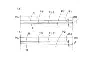
一方、発光面21からの光L2Uは、下のレンズ部3Dの下の入射面30Dの上部から入射してかつ下のレンズ部3Dの出射面31の基準光軸Zより下方の部分であって光L1Dの出射部分より上方の部分から、図4(A)に示す像I2Uとして、出射する。このとき、この出射光は、図1(A)に示すように、レンズ3の色収差による分光色として出射する。すなわち、黄緑色光YGに対して赤色光Rが下向きでかつ青色光Bが上向きで出射する。この出射光の分光幅W2は、図6(A)、(B)に示すように、上のレンズ部3Uの上部からの出射光の分光幅W1より小さい(狭い)。この出射光は、図2(B)、図5(B)に示す第2部分配光パターンP2のカットオフラインCL2を有する上縁の部分P2Uを形成する。 On the other hand, the light L2U from the
また、発光面21からの光L2Dは、下のレンズ部3Dの下の入射面30Dの下端から入射してかつ下のレンズ部3Dの出射面31の下部から、図4(B)に示す像I2Dとして、出射する。このとき、この出射光は、図1(A)に示すように、レンズ3の色収差による分光色として出射する。すなわち、黄緑色光YGに対して赤色光Rが下向きでかつ青色光Bが上向きで出射する。この出射光の分光幅は、下のレンズ部3Dの上部からの出射光の分光幅W2より大きい。この出射光は、図2(B)、図5(B)に示す第2部分配光パターンP2の下縁の部分P2Dを形成する。 Also, the light L2D from the
上のレンズ部3Uから照射された第1部分配光パターンP1と、下のレンズ部3Dから照射された第2部分配光パターンP2とは、合成されて、図2(C)、図5(C)に示すコーナリングランプ用配光パターンCPを形成する。コーナリングランプ用配光パターンCPの上縁の部分には、カットオフラインCLを有する。 The first partial light distribution pattern P1 irradiated from the
このとき、上のレンズ部3Uの上部から分光されて出射された上向きの赤色光Rおよび下向きの青色光Bと、下のレンズ部3Dの上部から分光されて出射された下向きの赤色光Rおよび上向きの青色光Bとは、混合して目立たなくなる。すなわち、レンズ3の色収差による分光色が目立たなくなる。 At this time, the upward red light R and the downward blue light B that are split and emitted from the upper part of the
(実施形態1の効果の説明)
この実施形態1にかかる車両用灯具1は、以上のごとき構成および作用からなり、以下、その効果について説明する。(Description of the effect of Embodiment 1)
The
この実施形態1にかかる車両用灯具1は、レンズ直射型であるから、半導体型光源2からの光LU、LC、LDを、レンズ3に直接入射させてかつそのレンズ3からコーナリングランプ用配光パターンCPとして出射(照射)させるものである。このために、設計通りに、下のレンズ部3Dの下部が、第1部分配光パターンP1の上縁と重なる第2部分配光パターンP2の上縁を形成することができる。これにより、設計通りに、上のレンズ部3Uの上部により形成される第1部分配光パターンP1の上縁における分光色と、下のレンズ部3Dの下部により形成される第2部分配光パターンP2の上縁における分光色とが、混合して効率良く分光色を目立たなくすることができる。 Since the
すなわち、図6(A)に示す第1部分配光パターンP1のカットオフラインCL1(配光制御の設計基準となっている黄緑色光YG)よりも上の赤色光Rと、図6(B)に示す第2部分配光パターンP2のカットオフラインCL2(配光制御の設計基準となっている黄緑色光YG)よりも上の青色光Bとは、混合して目立たなくなる。 That is, the red light R above the cut-off line CL1 of the first partial light distribution pattern P1 shown in FIG. 6A (the yellow-green light YG, which is the design standard for light distribution control), and FIG. And the blue light B above the cut-off line CL2 (yellowish green light YG which is a design standard for light distribution control) of the second partial light distribution pattern P2 shown in FIG.
また、図6(A)に示す第1部分配光パターンP1のカットオフラインCL1よりも下の青色光Bは、図6(B)に示す第2部分配光パターンP2のカットオフラインCL2よりも下の赤色光RおよびカットオフラインCL2よりも下方の出射光と混合して目立たなくなる。一方、図6(B)に示す第2部分配光パターンP2のカットオフラインCL2よりも下の赤色光Rは、図6(A)に示す第1部分配光パターンP1のカットオフラインCL1よりも下の青色光BおよびカットオフラインCL1よりも下方の出射光と混合して目立たなくなる。 Further, the blue light B below the cut-off line CL1 of the first partial light distribution pattern P1 shown in FIG. 6A is lower than the cut-off line CL2 of the second partial light distribution pattern P2 shown in FIG. 6B. The red light R and the outgoing light below the cut-off line CL2 are mixed and become inconspicuous. On the other hand, the red light R below the cut-off line CL2 of the second partial light distribution pattern P2 shown in FIG. 6B is lower than the cut-off line CL1 of the first partial light distribution pattern P1 shown in FIG. The blue light B and the outgoing light below the cut-off line CL1 are mixed and become inconspicuous.
この実施形態1にかかる車両用灯具1は、上の入射面30Uと下の入射面30Dとが交差線32を介して隣り合うものであるから、レンズ3の入射面30において段差がない。この結果、レンズ3の成形金型の構造が簡単となり、成形金型の耐久性が向上する。しかも、レンズ3を簡単に成形することができ、製造コストを安価にすることができる。 In the
この実施形態1にかかる車両用灯具1は、図5(C)に示すように、コーナリングランプ用配光パターンCPのカットオフラインCLを有する上縁の部分の光度(照度)が高いので、遠方の視認性が向上する。これにより、交通安全に貢献することができる。 As shown in FIG. 5C, the
しかも、この実施形態1にかかる車両用灯具1は、図5(C)に示すように、コーナリングランプ用配光パターンCPのカットオフラインCLを有する上縁の部分の光度(照度)が高く、中間の部分から下縁の部分にかけての光度(照度)が徐々に低くなる。この結果、ドライバーから見て、コーナリングランプ用配光パターンCPの下縁の部分および外側(右側)の部分の明るさが徐々に変化(グラデーション)して暗くなるので、違和感がなく、視認性が向上するので、交通安全に貢献することができる。 In addition, as shown in FIG. 5C, the
この実施形態1にかかる車両用灯具1は、第1部分配光パターンP1の光度(照度)を、像I1U、I1C、I1Dに基づいて、図5(A)に示すように、上縁の部分P1Uから中間の部分P1Cを経て下縁の部分P1Dにかけて徐々に低くなるように変化(グラデーション)するように配光制御しているものである。このために、コーナリングランプ用配光パターンCPの配光設計が容易である。 In the
この実施形態1にかかる車両用灯具1は、レンズ3の出射面31がひとつの面からなるので、出射面31には交差線などがなく、見栄えが良い。 In the
(実施形態2の構成の説明)
図7〜図10は、この発明にかかる車両用灯具の実施形態2を示す。以下、この実施形態2にかかる車両用灯具の構成について説明する。図中、図1〜図6と同符号は、同一のものを示す。(Description of Configuration of Embodiment 2)
FIGS. 7-10
この実施形態2の車両用灯具は、図8、図9に示すように、青色の光を放射する発光チップ20に黄色の蛍光体22を覆うものである。このために、上のレンズ部3Uから照射される第1部分配光パターンP1のカットオフラインCL1(配光制御の設計基準となっている黄緑色光YG)よりも上には、図7(A)に示すように、黄色の蛍光体22による黄色光(図10(A)中の破線を参照)YEが強い。一方、下のレンズ部3Dから照射される第2部分配光パターンP2のカットオフラインCL2(配光制御の設計基準となっている黄緑色光YG)よりも下には、図7(B)に示すように、黄色の蛍光体22による黄色光YEが強い。 As shown in FIGS. 8 and 9, the vehicular lamp according to the second embodiment covers a
また、第2部分配光パターンP2の下縁には、黄色の蛍光体22による黄色光YE(図10(B)中の破線を参照)がやや強い。一方、第1部分配光パターンP1の下縁は、拡散されているので、第1部分配光パターンP1の下縁の黄色光は、やや弱く目立たない。 Further, yellow light YE (see the broken line in FIG. 10B) by the
この実施形態2の車両用灯具は、図10に示すように、第2部分配光パターンP2の上縁のカットオフラインCL2が第1部分配光パターンP1の上縁のカットオフラインCL1よりも上に位置する。すなわち、第1部分配光パターンP1のカットオフラインCL1とスクリーンの左右の水平線HL−HRとの間の上下角度(上下幅)θ1°は、この例では図7(A)に示すように約1°であり、第2部分配光パターンP2のカットオフラインCL2とスクリーンの左右の水平線HL−HRとの間の上下角度(上下幅)θ2°この例では図7(B)に示すように約0.8°よりも大きい。 In the vehicular lamp of the second embodiment, as shown in FIG. 10, the cut-off line CL2 at the upper edge of the second partial light distribution pattern P2 is higher than the cut-off line CL1 at the upper edge of the first partial light distribution pattern P1. To position. That is, the vertical angle (vertical width) θ1 ° between the cut-off line CL1 of the first partial light distribution pattern P1 and the horizontal line HL-HR on the left and right of the screen is about 1 in this example as shown in FIG. Is the vertical angle (vertical width) θ2 ° between the cut-off line CL2 of the second partial light distribution pattern P2 and the horizontal line HL-HR on the left and right of the screen. In this example, as shown in FIG. Greater than 8 °.
(実施形態2の作用効果の説明)
この実施形態2の車両用灯具は、以上のごとき構成からなり、以下、その作用効果について説明する。(Description of the effect of Embodiment 2)
The vehicular lamp according to the second embodiment is configured as described above, and the operation and effect thereof will be described below.
半導体型光源2を点灯する。すると、上のレンズ部3Uから図10(A)に示すカットオフラインCL1を有する第1部分配光パターンP1が照射される。また、下のレンズ部3Dから図10(B)に示すカットオフラインCL2を有する第2部分配光パターンP2が照射される。 The
そして、カットオフラインCL1を有する第1部分配光パターンP1とカットオフラインCL2を有する第2部分配光パターンP2とが合成されて、図10(C)に示すコーナリングランプ用配光パターンCPが形成される。このとき、第2部分配光パターンP2のカットオフラインCL2が第1部分配光パターンP1のカットオフラインCL1よりも上に位置する。このために、第1部分配光パターンP1の黄色光YEは、第2部分配光パターンP2のカットオフラインCL2よりも上の青色光Bと混合して、目立たなくなる。一方、第2部分配光パターンP2の黄色光YEは、第1部分配光パターンP1のカットオフラインCL1よりも下の青色光BおよびカットオフラインCL1よりも下方の出射光と混合して、目立たなくなる。また、第2部分配光パターンP2の下縁の黄色光YEは、第1部分配光パターンP1の中間の部分の光と混合して、目立たなくなる。なお、第1部分配光パターンP1の下縁は、拡散されているので、第1部分配光パターンP1の下縁の黄色光は、目立たない。 Then, the first partial light distribution pattern P1 having the cut-off line CL1 and the second partial light distribution pattern P2 having the cut-off line CL2 are combined to form a light distribution pattern CP for cornering lamp shown in FIG. The At this time, the cut-off line CL2 of the second partial light distribution pattern P2 is positioned above the cut-off line CL1 of the first partial light distribution pattern P1. For this reason, the yellow light YE of the first partial light distribution pattern P1 is mixed with the blue light B above the cutoff line CL2 of the second partial light distribution pattern P2, and becomes inconspicuous. On the other hand, the yellow light YE of the second partial distribution light pattern P2 is mixed with the blue light B below the cutoff line CL1 and the outgoing light below the cutoff line CL1 of the first partial distribution light pattern P1, and becomes inconspicuous. . Further, the yellow light YE at the lower edge of the second partial light distribution pattern P2 is mixed with the light in the middle of the first partial light distribution pattern P1, and becomes inconspicuous. Since the lower edge of the first partial light distribution pattern P1 is diffused, the yellow light at the lower edge of the first partial light distribution pattern P1 is not noticeable.
(実施形態1、2以外の例の説明)
この実施形態1、2においては、コーナリングランプについて説明するものである。ところが、この発明においては、コーナリングランプ以外の車両用灯具、たとえば、ロービーム用ヘッドランプ、ハイビーム用ヘッドランプ、フォグランプなどの車両用灯具に使用することができる。(Description of examples other than
In the first and second embodiments, a cornering lamp will be described. However, the present invention can be used for vehicle lamps other than the cornering lamp, for example, vehicle lamps such as a low beam headlamp, a high beam headlamp, and a fog lamp.
ロービーム用ヘッドランプは、上縁にカットオフラインCLを有するコーナリングランプ用配光パターンCPを照射するコーナリングランプと同様に、上縁にカットオフラインを有するロービーム配光パターンを照射するものである。このために、ロービーム用ヘッドランプの場合は、コーナリングランプの場合と同様に、ロービーム配光パターンのカットオフラインの上縁の分光色を目立たなくするものである。 The low-beam headlamp irradiates a low-beam light distribution pattern having a cut-off line on the upper edge in the same manner as a cornering lamp irradiating a cornering lamp light-distribution pattern CP having a cut-off line CL on the upper edge. For this reason, in the case of the headlamp for low beam, the spectral color at the upper edge of the cut-off line of the low beam distribution pattern is made inconspicuous, as in the case of the cornering lamp.
一方、ハイビーム用ヘッドランプは、上縁にカットオフラインCLを有するコーナリングランプ用配光パターンCPを照射するコーナリングランプ、また、上縁にカットオフラインを有するロービーム配光パターンを照射するロービーム用ヘッドランプと異なり、上縁にカットオフラインを有しないハイビーム配光パターンを照射するものである。このハイビーム配光パターンは、ほぼ中央部に最大光度帯(最大照度帯、ホットゾーン)を有し、この最大光度帯から周辺に行くに従って光度(照度)が徐々に低下していく配光パターンである。このハイビーム配光パターンの下縁は、車両用灯具の取付位置の高さが路面から約80cmの場合において、車両から前方約15mの路面に位置する。このために、ハイビーム配光パターンを照射時において、車両から前方約15mの路面には、ハイビーム配光パターンの下縁の分光色が目立つ場合がある。そこで、ハイビーム用ヘッドランプの場合は、コーナリングランプの場合やロービーム用ヘッドランプの場合と異なり、ハイビーム配光パターンの下縁の分光色を目立たなくするものである。 On the other hand, the high beam headlamp includes a cornering lamp that irradiates a light distribution pattern CP for a cornering lamp having a cut-off line CL on an upper edge, and a low-beam headlamp that irradiates a low-beam light distribution pattern having a cut-off line on an upper edge. In contrast, a high beam light distribution pattern that does not have a cut-off line at the upper edge is irradiated. This high beam light distribution pattern has a maximum luminous intensity band (maximum illuminance band, hot zone) in the central part, and the luminous intensity (illuminance) gradually decreases from this maximum luminous intensity band to the periphery. is there. The lower edge of the high beam light distribution pattern is located on the road surface approximately 15 m ahead of the vehicle when the mounting position of the vehicle lamp is about 80 cm from the road surface. For this reason, when the high beam light distribution pattern is irradiated, the spectral color of the lower edge of the high beam light distribution pattern may be conspicuous on the road surface approximately 15 m ahead from the vehicle. Therefore, in the case of a high beam headlamp, unlike the case of a cornering lamp or a low beam headlamp, the spectral color at the lower edge of the high beam light distribution pattern is made inconspicuous.
また、この実施形態1、2においては、レンズ3の入射面30を上下に2つに区画するものである。ところが、この発明においては、レンズ3の入射面30を上下に3つ以上に区画しても良い。この場合においては、上のレンズ部から照射される第1部分配光パターンと、下のレンズ部から照射される第2部分配光パターンと、中間の1個のレンズ部もしくは複数個のレンズ部から照射される1個の中間配光パターンもしくは複数個の配光パターンと、を合成して所定の配光パターンが形成される。 In the first and second embodiments, the incident surface 30 of the
さらに、この実施形態1、2においては、レンズ3の入射面30を上下に少なくとも2つに区画するものである。ところが、この発明においては、レンズ3の出射面31を上下に少なくとも2つに区画しても良い。 Further, in the first and second embodiments, the incident surface 30 of the
さらにまた、この実施形態1、2においては、レンズ3の入射面30をレンズ3の基準光軸Zに対して下において上下に2つに区画するものである。ところが、この発明においては、レンズ3の入射面30あるいは出射面31をレンズ3の基準光軸Zに対して上において上下に2つに区画するものであっても良い。 Furthermore, in the first and second embodiments, the incident surface 30 of the
さらにまた、この発明においては、上のレンズ部3Uの上部よりも上の部分(すなわち、レンズ3の上端部分)に、オーバーヘッドサイン配光パターンを形成するレンズ部を形成しても良い。 Furthermore, in the present invention, a lens portion that forms an overhead sign light distribution pattern may be formed in a portion above the upper portion of the
1 車両用灯具
2 半導体型光源
20 発光チップ
21 発光面
22 黄色の蛍光体
3 レンズ
3U 上のレンズ部
3D 下のレンズ部
30 入射面
30U 上の入射面
30D 下の入射面
31 出射面
32 交差線
300 一般のレンズ
B 青色光
CL、CL1、CL2 カットオフライン
CP コーナリングランプ用配光パターン
F 基準焦点
HL−HR スクリーンの左右の水平線
I1U、I1C、I1D、I2U、I2D 像
L1U、L1C、L1D、L2U、L2D 光
O 中心
P1 第1部分配光パターン
P1U 上縁の部分
P1C 中間の部分
P1D 下縁の部分
P2 第2部分配光パターン
P2U 上縁の部分
P2D 下縁の部分
R 赤色光
W1、W2 分光幅
X X軸
Y Y軸
YE 黄色光
YG 黄緑色光
Z 基準光軸(Z軸)DESCRIPTION OF
Claims (4)
Translated fromJapanese前記レンズは、入射面と、出射面と、から構成されていて、
前記入射面もしくは前記出射面のいずれか一方は、上下に少なくとも2つに区画されていて、
上の区画面を有する上のレンズ部は、第1部分配光パターンを形成し、
下の区画面を有する下のレンズ部は、前記第1部分配光パターンと重なる第2部分配光パターンを形成し、
前記上のレンズ部の上部は、前記第1部分配光パターンの上縁の部分を形成し、
前記下のレンズ部の上部は、前記第1部分配光パターンの上縁の部分と重なる前記第2部分配光パターンの上縁の部分を形成し、
あるいは、
前記上のレンズ部の下端は、前記第1部分配光パターンの下縁の部分を形成し、
前記下のレンズ部の下端は、前記第1部分配光パターンの下縁の部分と重なる前記第2部分配光パターンの下縁の部分を形成し、
前記半導体型光源は、青色の光を放射するチップと、前記チップを覆う黄色の蛍光体と、から構成されていて、
上下幅が前記第1部分配光パターンの上下幅より小さい前記第2部分配光パターンの上縁は、前記第1部分配光パターンの上縁よりも上に位置し、あるいは、上下幅が前記第2部分配光パターンの上下幅より小さい前記第1部分配光パターンの下縁は、前記第2部分配光パターンの下縁よりも下に位置する、
ことを特徴とする車両用灯具。A semiconductor-type light source, and a lens that directly enters the light from the semiconductor-type light source and emits it as a predetermined light distribution pattern,
The lens is composed of an entrance surface and an exit surface,
Either the entrance surface or the exit surface is partitioned into at least two in the vertical direction,
The upper lens part having the upper section screen forms a first part distribution light pattern,
A lower lens portion having a lower section screen forms a second partial light distribution pattern that overlaps the first partial light distribution pattern,
Top of the lens portion on the forms the upper edgeportion of the first portion light distribution pattern,
Top of the lens portion under the form a top edgeportion of the second portion light distribution pattern overlapping an upper edgeportion of the first portion light distribution pattern,
Or
The lower end of the lens portion on the formpart of the lower edge of the first portion light distribution pattern,
The lower end of the lens portion under the forms theportion of the lower edge of the second partial light distribution pattern that overlaps theportion of the lower edge of the first portion light distribution pattern,
The semiconductor-type light source is composed of a chip that emits blue light, and a yellow phosphor that covers the chip,
The upper edge of the second partial light distribution pattern whose vertical width is smaller than the vertical width of the first partial light distribution pattern is located above the upper edge of the first partial light distribution pattern, or the vertical width is The lower edge of the first partial light distribution pattern, which is smaller than the vertical width of the second partial light distribution pattern, is located below the lower edge of the second partial light distribution pattern.
A vehicular lamp characterized by the above.
ことを特徴とする請求項1に記載の車両用灯具。At least two or more of the ward screens are adjacent to each other through an intersection line.
The vehicular lamp according to claim 1.
前記レンズは、入射面と、出射面と、から構成されていて、
前記入射面は、前記レンズの基準光軸に対して下において上下に2つに区画されていて、
上の入射面を有する上のレンズ部は、第1部分配光パターンを形成し、
下の入射面を有する下のレンズ部は、上下幅が前記第1部分配光パターンの上下幅よりも小さく、前記第1部分配光パターンと重なる第2部分配光パターンを形成し、
前記上のレンズ部の上部は、前記第1部分配光パターンの上縁の前記カットオフラインを有する部分を形成し、
前記下のレンズ部の上部は、前記第1部分配光パターンの上縁の前記カットオフラインを有する部分と重なる前記第2部分配光パターンの上縁の前記カットオフラインを有する部分を形成し、
前記半導体型光源は、青色の光を放射するチップと、前記チップを覆う黄色の蛍光体と、から構成されていて、
前記第2部分配光パターンの上縁は、前記第1部分配光パターンの上縁よりも上に位置する、
ことを特徴とする車両用灯具。A semiconductor-type light source, and a lens that directly emits light from the semiconductor-type light source and emits it as a predetermined light distribution pattern having a cut-off line,
The lens is composed of an entrance surface and an exit surface,
The incident surface is divided into two vertically below the reference optical axis of the lens,
The upper lens part having the upper incident surface forms a first part distribution light pattern,
The lower lens portion having a lower incident surface has a vertical width smaller than the vertical width of the first partial light distribution pattern, and forms a second partial light distribution pattern that overlaps the first partial light distribution pattern,
The upper part of the upper lens part forms a part having the cut-off line of the upper edge of the first part distribution light pattern,
The upper part of the lower lens part forms a part having the cut-off line on the upper edge of the second partial light distribution pattern overlapping the part having the cut-off line on the upper edge of the first partial light distribution pattern,
The semiconductor-type light source is composed of a chip that emits blue light, and a yellow phosphor that covers the chip,
An upper edge of the second partial light distribution pattern is located above an upper edge of the first partial light distribution pattern.
A vehicular lamp characterized by the above.
ことを特徴とする請求項3に記載の車両用灯具。The upper incident surface and the lower incident surface are adjacent to each other through a crossing line,
The vehicular lamp according to claim 3.
Priority Applications (5)
| Application Number | Priority Date | Filing Date | Title |
|---|---|---|---|
| JP2013184204AJP6409259B2 (en) | 2013-09-05 | 2013-09-05 | Vehicle lighting |
| CN201480048842.2ACN105531532B (en) | 2013-09-05 | 2014-08-28 | Lamps apparatus for vehicle |
| PCT/JP2014/072538WO2015033848A1 (en) | 2013-09-05 | 2014-08-28 | Vehicular lighting |
| US14/916,649US9945529B2 (en) | 2013-09-05 | 2014-08-28 | Vehicular lighting |
| EP14843022.6AEP3043109B1 (en) | 2013-09-05 | 2014-08-28 | Vehicular lighting |
Applications Claiming Priority (1)
| Application Number | Priority Date | Filing Date | Title |
|---|---|---|---|
| JP2013184204AJP6409259B2 (en) | 2013-09-05 | 2013-09-05 | Vehicle lighting |
Related Child Applications (1)
| Application Number | Title | Priority Date | Filing Date |
|---|---|---|---|
| JP2018180049ADivisionJP6733715B2 (en) | 2018-09-26 | 2018-09-26 | Vehicle lighting |
Publications (2)
| Publication Number | Publication Date |
|---|---|
| JP2015053133A JP2015053133A (en) | 2015-03-19 |
| JP6409259B2true JP6409259B2 (en) | 2018-10-24 |
Family
ID=52628323
Family Applications (1)
| Application Number | Title | Priority Date | Filing Date |
|---|---|---|---|
| JP2013184204AActiveJP6409259B2 (en) | 2013-09-05 | 2013-09-05 | Vehicle lighting |
Country Status (5)
| Country | Link |
|---|---|
| US (1) | US9945529B2 (en) |
| EP (1) | EP3043109B1 (en) |
| JP (1) | JP6409259B2 (en) |
| CN (1) | CN105531532B (en) |
| WO (1) | WO2015033848A1 (en) |
Families Citing this family (5)
| Publication number | Priority date | Publication date | Assignee | Title |
|---|---|---|---|---|
| JP7103790B2 (en) | 2015-06-25 | 2022-07-20 | コーニンクレッカ フィリップス エヌ ヴェ | Medical interventional imaging device |
| JP6746896B2 (en)* | 2015-11-10 | 2020-08-26 | 市光工業株式会社 | Vehicle lighting |
| DE102017105027A1 (en) | 2017-03-09 | 2018-09-13 | Automotive Lighting Reutlingen Gmbh | Motor vehicle headlamps light module |
| WO2021112063A1 (en)* | 2019-12-04 | 2021-06-10 | 株式会社小糸製作所 | Vehicle headlight |
| KR102327018B1 (en)* | 2020-01-31 | 2021-11-16 | 현대모비스 주식회사 | Lamp for automobile and automobile including the same |
Family Cites Families (13)
| Publication number | Priority date | Publication date | Assignee | Title |
|---|---|---|---|---|
| JPH01186701A (en) | 1988-01-18 | 1989-07-26 | Ichikoh Ind Ltd | projector headlight |
| JP4002159B2 (en)* | 2002-09-03 | 2007-10-31 | 株式会社小糸製作所 | Vehicle headlamp |
| JP4131845B2 (en)* | 2003-09-29 | 2008-08-13 | 株式会社小糸製作所 | Lamp unit and vehicle headlamp |
| JP4339143B2 (en) | 2004-02-10 | 2009-10-07 | 株式会社小糸製作所 | Vehicle lamp unit |
| JP4597890B2 (en)* | 2006-03-29 | 2010-12-15 | 株式会社小糸製作所 | Vehicle headlamp lamp unit |
| JP4782064B2 (en)* | 2007-04-10 | 2011-09-28 | 株式会社小糸製作所 | Vehicle lamp unit |
| JP2009181845A (en)* | 2008-01-31 | 2009-08-13 | Koito Mfg Co Ltd | Vehicular headlight |
| JP5445923B2 (en)* | 2009-09-04 | 2014-03-19 | スタンレー電気株式会社 | Vehicle lighting |
| JP5516854B2 (en) | 2009-10-08 | 2014-06-11 | スタンレー電気株式会社 | Vehicle lighting |
| JP5475395B2 (en)* | 2009-10-23 | 2014-04-16 | スタンレー電気株式会社 | Vehicle lighting |
| JP5519400B2 (en) | 2010-05-20 | 2014-06-11 | 株式会社小糸製作所 | Lighting fixtures for vehicles |
| JP5666942B2 (en)* | 2011-02-24 | 2015-02-12 | 株式会社小糸製作所 | Vehicle lighting |
| JP5975674B2 (en)* | 2011-11-29 | 2016-08-23 | 株式会社小糸製作所 | Lighting fixtures for vehicles |
- 2013
- 2013-09-05JPJP2013184204Apatent/JP6409259B2/enactiveActive
- 2014
- 2014-08-28USUS14/916,649patent/US9945529B2/enactiveActive
- 2014-08-28WOPCT/JP2014/072538patent/WO2015033848A1/enactiveApplication Filing
- 2014-08-28CNCN201480048842.2Apatent/CN105531532B/enactiveActive
- 2014-08-28EPEP14843022.6Apatent/EP3043109B1/enactiveActive
Also Published As
| Publication number | Publication date |
|---|---|
| CN105531532B (en) | 2018-08-24 |
| US20160201868A1 (en) | 2016-07-14 |
| JP2015053133A (en) | 2015-03-19 |
| CN105531532A (en) | 2016-04-27 |
| EP3043109A4 (en) | 2017-08-16 |
| WO2015033848A1 (en) | 2015-03-12 |
| EP3043109B1 (en) | 2021-03-31 |
| EP3043109A1 (en) | 2016-07-13 |
| US9945529B2 (en) | 2018-04-17 |
Similar Documents
| Publication | Publication Date | Title |
|---|---|---|
| JP5481764B2 (en) | Vehicle lighting | |
| EP2620697A2 (en) | Vehicle lighting unit with projection lens and LED | |
| JP5526453B2 (en) | Vehicle headlamp | |
| US20120206931A1 (en) | Vehicle lighting device | |
| JP5919685B2 (en) | Vehicle headlamp | |
| JP5565094B2 (en) | Vehicle lamp unit | |
| WO2014208655A1 (en) | Vehicle lamp fitting | |
| WO2016043059A1 (en) | Vehicle lamp | |
| JP6409259B2 (en) | Vehicle lighting | |
| CN104797881B (en) | Headlight for automobile | |
| JP6303587B2 (en) | Vehicle lighting | |
| JP6119279B2 (en) | Vehicle headlamp | |
| JP6064439B2 (en) | Vehicle headlamp | |
| JP6264847B2 (en) | Vehicle lighting | |
| JP6733715B2 (en) | Vehicle lighting | |
| JP6136213B2 (en) | Vehicle lighting | |
| CN113710954A (en) | Vehicle lamps | |
| JP6402592B2 (en) | Vehicle headlamp | |
| JP6394080B2 (en) | Vehicle lighting | |
| JP2016062668A (en) | Vehicular lighting fixture | |
| JP6277612B2 (en) | Vehicle lighting | |
| JP6264848B2 (en) | Vehicle lighting | |
| JP6496976B2 (en) | Vehicle headlamp | |
| JP6299265B2 (en) | Vehicle headlamp | |
| JP2016134200A (en) | Vehicle lighting |
Legal Events
| Date | Code | Title | Description |
|---|---|---|---|
| A621 | Written request for application examination | Free format text:JAPANESE INTERMEDIATE CODE: A621 Effective date:20160831 | |
| A131 | Notification of reasons for refusal | Free format text:JAPANESE INTERMEDIATE CODE: A131 Effective date:20170627 | |
| A521 | Request for written amendment filed | Free format text:JAPANESE INTERMEDIATE CODE: A523 Effective date:20170814 | |
| A131 | Notification of reasons for refusal | Free format text:JAPANESE INTERMEDIATE CODE: A131 Effective date:20180206 | |
| A521 | Request for written amendment filed | Free format text:JAPANESE INTERMEDIATE CODE: A523 Effective date:20180326 | |
| TRDD | Decision of grant or rejection written | ||
| A01 | Written decision to grant a patent or to grant a registration (utility model) | Free format text:JAPANESE INTERMEDIATE CODE: A01 Effective date:20180828 | |
| A61 | First payment of annual fees (during grant procedure) | Free format text:JAPANESE INTERMEDIATE CODE: A61 Effective date:20180910 | |
| R150 | Certificate of patent or registration of utility model | Ref document number:6409259 Country of ref document:JP Free format text:JAPANESE INTERMEDIATE CODE: R150 | |
| R250 | Receipt of annual fees | Free format text:JAPANESE INTERMEDIATE CODE: R250 | |
| R250 | Receipt of annual fees | Free format text:JAPANESE INTERMEDIATE CODE: R250 | |
| R250 | Receipt of annual fees | Free format text:JAPANESE INTERMEDIATE CODE: R250 | |
| R250 | Receipt of annual fees | Free format text:JAPANESE INTERMEDIATE CODE: R250 |