JP6408196B2 - Housing structure for vehicle door mirrors - Google Patents
Housing structure for vehicle door mirrorsDownload PDFInfo
- Publication number
- JP6408196B2 JP6408196B2JP2012219765AJP2012219765AJP6408196B2JP 6408196 B2JP6408196 B2JP 6408196B2JP 2012219765 AJP2012219765 AJP 2012219765AJP 2012219765 AJP2012219765 AJP 2012219765AJP 6408196 B2JP6408196 B2JP 6408196B2
- Authority
- JP
- Japan
- Prior art keywords
- housing
- visor
- plate portion
- extension plate
- claw
- Prior art date
- Legal status (The legal status is an assumption and is not a legal conclusion. Google has not performed a legal analysis and makes no representation as to the accuracy of the status listed.)
- Active
Links
Images


Landscapes
- Rear-View Mirror Devices That Are Mounted On The Exterior Of The Vehicle (AREA)
- Connection Of Plates (AREA)
Description
Translated fromJapanese本発明は、後方確認用のミラーが取り付けられるバイザーと、当該バイザーを覆うハウジングとを備えた車両用ドアミラーのハウジング取付構造に関するものである。 The present invention relates to a housing mounting structure for a vehicle door mirror that includes a visor to which a mirror for rearward confirmation is mounted and a housing that covers the visor.
従来から、車両用ドアミラーでは、ミラーが取り付けられるバイザーに、例えば電動格納ユニット等が組み付けられており、さらに、そのユニットをミラーとは反対側から覆うためのハウジングがバイザーとは別体に構成されて該バイザーに取り付けられている。 Conventionally, in a vehicle door mirror, an electric storage unit, for example, is assembled to a visor to which the mirror is attached, and a housing for covering the unit from the side opposite to the mirror is configured separately from the visor. Attached to the visor.
このような構成の車両用ドアミラーとしては、例えば特許文献1に開示されているものがあり、特許文献1では、ハウジングをバイザーに対して着脱可能に取り付けることができるようになっている。すなわち、バイザーの縁部には、ハウジング側へ延出する板状のフック片が形成され、このフック片の先端側には板厚方向に貫通する開口部が形成されている。一方、ハウジングの縁部には、フック片に対応する部位に、フック片の延出方向と直交する方向にハウジングの内方へ向けて突出する突起が形成されている。 For example,
ハウジングをバイザーに取り付ける際には、ハウジングをバイザーに接近させていき、ハウジングの突起をバイザーのフック片の先端側に当接させながらフック片をバイザーの内方へ弾性変形させていき、フック片の開口部に突起が達した瞬間にフック片の形状が復元して突起が開口部に入り込み、これにより、突起とフック片とが係合してハウジングの縁部がバイザーに固定される。 When attaching the housing to the visor, the housing is moved closer to the visor, and the hook piece is elastically deformed inward of the visor while the projection of the housing is in contact with the tip side of the hook piece of the visor. As soon as the projection reaches the opening, the shape of the hook piece is restored, and the projection enters the opening. As a result, the projection and the hook piece are engaged, and the edge of the housing is fixed to the visor.
ところで、例えば電動格納ユニット等が故障することがあり、その場合にはユニットの交換、修理を行うためにハウジングをバイザーから取り外す必要がある。 By the way, for example, an electric storage unit or the like may break down. In this case, it is necessary to remove the housing from the visor in order to replace or repair the unit.
しかしながら、特許文献1では、走行時の振動等によってハウジングがバイザーから不意に外れないようにハウジングを強固に固定しておく必要があることから、突起におけるフック片の開口部周縁との接触部分は、ハウジングの取り外し方向と直交する方向に延びる係合面で構成されており、突起が開口部から容易に抜けないようになっている。 However, in
このため、バイザーに一旦取り付けたハウジングを取り外そうとして外力を加えた際に、突起がフック片の開口部から抜けにくく、開口部周縁に対して取り外し方向に強い引っ張り力が作用することになる。このとき、フック片は単純な板状であるため、突起からの引っ張り力を受けた開口部周縁が破損してしまう場合がある。 For this reason, when an external force is applied to remove the housing once attached to the visor, the projections are difficult to come off from the opening of the hook piece, and a strong pulling force acts on the periphery of the opening in the removing direction. . At this time, since the hook piece has a simple plate shape, the periphery of the opening that receives the pulling force from the protrusion may be damaged.
フック片が破損してしまうとバイザーを再利用することができず、ひいては、車両用ドアミラーの修理費用の高騰を招く結果となる。 If the hook piece is damaged, the visor cannot be reused, and as a result, the repair cost of the vehicle door mirror increases.
本発明は、かかる点に鑑みてなされたものであり、その目的とするところは、ハウジングをバイザーに着脱可能に取り付ける場合に、走行時等にハウジングが不意に脱落しないようにしながら、交換や修理時には両者の破損を招くことなくハウジングをバイザーから取り外すことができるようにして部品の再利用を可能にし、もって、車両用ドアミラーの修理費用の低廉化を図ることにある。 The present invention has been made in view of the above points, and the object of the present invention is to replace or repair the housing while the housing is detachably attached to the visor while preventing the housing from accidentally falling off during traveling. In some cases, the housing can be removed from the visor without causing damage to both parts so that the parts can be reused, thereby reducing the repair cost of the vehicle door mirror.
上記目的を達成するために、本発明に係る車両用ドアミラーのハウジング取付構造では、取り外し時に破損しにくい爪嵌合構造を採用した。 In order to achieve the above object, the housing mounting structure for a vehicle door mirror according to the present invention employs a claw fitting structure that is not easily damaged when removed.
第1の発明は、後方確認用のミラーが取り付けられるバイザーと、当該バイザーを覆うためのハウジングとを備えた車両用ドアミラーのハウジング取付構造において、
上記ハウジングの本体部は、上記車両用ドアミラーの側面に回り込むように湾曲形成された湾曲壁部を有し、
上記バイザーの縁部には、上記ハウジングへ向かって突出する係合爪が形成され、
上記ハウジングの湾曲壁部の縁部には、上記係合爪に対応する部位に、上記係合爪の突出方向と交差する方向に延出する延出板部と、該延出板部を補強する補強部とが形成され、該延出板部には、上記係合爪が挿入される係合孔が形成され、
上記延出板部における上記係合孔の周縁部の上記バイザー側の面には、上記バイザー側へ向けて突出する突起が形成され、該突起は突出方向基端側へ行くほど上記係合孔に接近するように形成された傾斜面を有し、
上記補強部は、上記ハウジングの上記湾曲壁部内面から突出して上記延出板部における上記突起が形成された面とは反対側の面に連なるリブであり、
上記ハウジングと上記バイザーとの一方を他方に接近する方向に移動させて上記ハウジングを上記バイザーに取り付けた状態で、上記係合爪が上記係合孔に挿入されて該係合孔の周縁部に係合することを特徴とするものである。A first invention is a housing mounting structure for a vehicle door mirror comprising a visor to which a mirror for rearward confirmation is attached and a housing for covering the visor.
The main body portion of the housing has a curved wall portion that is curved so as to go around the side surface of the vehicle door mirror,
An engaging claw that protrudes toward the housing is formed at the edge of the visor.
At the edge of the curved wall portion of the housing, an extension plate portion extending in a direction intersecting the protruding direction of the engagement claw at a portion corresponding to the engagement claw, and the extension plate portion are reinforced A reinforcing portion is formed, and the extending plate portion is formed with an engaging hole into which the engaging claw is inserted,
A protrusion that protrudes toward the visor is formed on the visor-side surface of the peripheral edge of the engagement hole in the extension plate, and the protrusion extends toward the proximal end in the protruding direction. Aninclined surface formed so as to approach
The reinforcing portion is a rib that protrudes from the inner surface of the curved wall portion of the housing and continues to a surface opposite to the surface on which the protrusion is formed in the extension plate portion,
In a state where one of the housing and the visor is moved in a direction approaching the other and the housing is attached to the visor, the engagement claw is inserted into the engagement hole and is inserted into the peripheral portion of the engagement hole. It is characterized by engaging.
この構成によれば、ハウジングをバイザーに取り付ける際、例えばハウジングをバイザーに接近させていくと、係合爪の先端側が延出板部の係合孔に挿入されて係合爪が延出板部の係合孔周縁部に係合する。この係合状態で例えば車両走行時の振動によってハウジングがバイザーから離れる方向に力が作用したとしても、係合爪に対して延出板部が交差する方向に延出しているので、両者の係合状態が維持されてハウジングの不意の脱落が防止される。 According to this configuration, when the housing is attached to the visor, for example, when the housing is brought closer to the visor, the distal end side of the engaging claw is inserted into the engaging hole of the extending plate portion, and the engaging claw is extended to the extending plate portion. Engage with the peripheral edge of the engagement hole. Even if a force acts in a direction in which the housing moves away from the visor due to, for example, vibration during traveling of the vehicle in this engaged state, the extension plate portion extends in a direction intersecting the engaging claw. The combined state is maintained and the housing is prevented from being accidentally dropped.
一方、修理時等のようにハウジングをバイザーから取り外す場合には、係合爪が延出板部の係合孔の周縁部に係合した状態で係合孔から抜く方向に引っ張り力が作用することになる。このとき延出板部が補強部によって補強されているので、延出板部が破損することはなく、係合爪や延出板部の弾性変形を伴いながら係合爪が延出板部から抜けてハウジングがバイザーから外れる。よって、ハウジング及びバイザーの両者が破損することはないので再利用が可能になる。 On the other hand, when removing the housing from the visor, such as during repairs, a pulling force acts in the direction of pulling out from the engagement hole in a state where the engagement claw is engaged with the peripheral edge of the engagement hole of the extension plate portion. It will be. At this time, since the extending plate portion is reinforced by the reinforcing portion, the extending plate portion is not damaged, and the engaging claw is detached from the extending plate portion while accompanying elastic deformation of the engaging claw and the extending plate portion. The housing comes off from the visor. Therefore, both the housing and the visor are not damaged and can be reused.
また、ハウジングをバイザーから取り外す際、力のかかり方により、万が一、延出部が破損した場合、延出板部をハウジングに設けているので、高価なバイザーは再利用することが可能である。 Further, when the housing is removed from the visor, if the extension portion is damaged due to the application of force, the extension plate portion is provided in the housing, so that an expensive visor can be reused.
また、延出板部とハウジングの本体部とをリブによって繋ぐことで延出板部の補強効果が十分に得られるようになる。 Moreover, the reinforcement effect of an extension board part comes to be fully acquired by connecting an extension board part and the main-body part of a housing with a rib.
また、車両用ドアミラーのデザイン上、ドアミラーの側面に回り込むように湾曲形成された湾曲壁部を有する場合がある。この場合、湾曲壁部の内面に係合爪等を形成するのは、成形型の構造上、困難な場合があるが、湾曲壁部の縁部であれば、延出板部及び補強部を容易に形成することが可能になる。よって、湾曲壁部を有する場合に、湾曲壁部の縁部に延出板部及び補強部を形成することで、型構造の複雑化を招くことはない。 Moreover, the design of the vehicle door mirror may have a curved wall portion that is curved so as to go around the side surface of the door mirror. In this case, it may be difficult to form the engaging claws or the like on the inner surface of the curved wall due to the structure of the mold, but if it is an edge of the curved wall, the extending plate portion and the reinforcing portion are It can be easily formed. Therefore, when the curved wall portion is provided, the mold structure is not complicated by forming the extension plate portion and the reinforcing portion at the edge portion of the curved wall portion.
第1の発明によれば、係合爪の突出方向と交差する方向に延出する延出板部を形成し、この延出板部に形成した係合孔の周縁部に係合爪を係合させるようにしたので、走行時等にハウジングが不意に脱落するのを防止できる。しかも、修理時等にハウジングを取り外す際には、延出板部が補強部によって補強されているので、バイザー及びハウジングの破損を招くことなく部品を再利用することができ、もって、修理費用の低廉化を図ることができる。 According to the first invention, the extending plate portion extending in the direction intersecting the protruding direction of the engaging claw is formed, and the engaging claw is engaged with the peripheral portion of the engaging hole formed in the extending plate portion. Since they are combined, it is possible to prevent the housing from dropping off unexpectedly during traveling. Moreover, when removing the housing at the time of repair, etc., the extension plate portion is reinforced by the reinforcing portion, so that the parts can be reused without causing damage to the visor and the housing, so that the repair cost can be reduced. Cost reduction can be achieved.
また、係合爪をバイザーに形成し、延出板部をハウジングに形成したので、万が一、延出部が破損した場合に、高価なバイザーは再利用して安価なハウジングを交換すればよく、修理費用が高騰するのを回避できる。 In addition, since the engaging claw is formed in the visor and the extension plate part is formed in the housing, in the unlikely event that the extension part is damaged, the expensive visor may be reused and the inexpensive housing replaced. It is possible to avoid an increase in repair costs.
また、補強部がハウジングの本体部内面から突出して延出板部に連なるリブであるので、延出板部の補強効果を十分に得ることができ、破損を未然に防止することができる。 In addition, since the reinforcing portion is a rib that protrudes from the inner surface of the main body portion of the housing and continues to the extending plate portion, the reinforcing effect of the extending plate portion can be sufficiently obtained, and damage can be prevented in advance.
また、車両用ドアミラーのデザイン上の要求からハウジングに湾曲壁部を形成する場合に、湾曲壁部の縁部に延出板部及び補強部を形成することで、型構造の複雑化を招くことはなく、低コスト化を図ることができる。 In addition, when a curved wall portion is formed on a housing due to a design requirement of a vehicle door mirror, the extension plate portion and the reinforcing portion are formed on the edge portion of the curved wall portion, thereby complicating the mold structure. It is not possible to reduce the cost.
以下、本発明の実施形態を図面に基づいて詳細に説明する。尚、以下の好ましい実施形態の説明は、本質的に例示に過ぎず、本発明、その適用物或いはその用途を制限することを意図するものではない。 Hereinafter, embodiments of the present invention will be described in detail with reference to the drawings. It should be noted that the following description of the preferred embodiment is merely illustrative in nature, and is not intended to limit the present invention, its application, or its use.
図1は、本発明の実施形態に係るハウジング取付構造が適用された車両用ドアミラー1を示す斜視図である。図1の車両用ドアミラー1は、自動車の右側のフロントドアA(図1に仮想線で一部のみ示す)に固定され、運転者の後方確認のために用いられるものである。尚、図示しないが、自動車の右側のドアミラーは左側のドアミラーと左右対称構造であるだけなので、右側のドアミラーと同様に本発明を適用することができる。 FIG. 1 is a perspective view showing a
この実施形態の説明では、説明の便宜を図るために、車両前側を単に「前」といい、車両後側を単に「後」といい、車両左側を単に「左」といい、車両右側を単に「右」というものとする。 In the description of this embodiment, for convenience of explanation, the front side of the vehicle is simply referred to as “front”, the rear side of the vehicle is simply referred to as “rear”, the left side of the vehicle is simply referred to as “left”, and the right side of the vehicle is simply referred to as “right”. It shall be called “right”.
車両用ドアミラー1は、後方確認用のミラー2(図2に示す)と、ミラー2が取り付けられるバイザー3と、バイザー3を覆うハウジング4と、バイザー3をフロントドアAに固定するためのベース5とを備えている。 The
ベース5は、フロントドアAのサッシュ前端部に締結固定されており、左側(車両外側)へ突出している。 The
バイザー3は、樹脂材を成形してなるものであり、上下方向の寸法よりも左右方向の寸法が長い形状となっている。バイザー3の後面には、図3に示すようにミラー2を収容するためのミラー収容凹部10が前側へ窪むように形成されている。ミラー収容凹部10内には、図示しないが、ミラー2の他に、ミラー2が両面テープによって貼り付けられるミラーホルダと、ミラー2の角度を調整する角度調整ユニットも収容される。角度調整ユニットはミラー収容凹部10に固定される。 The
バイザー3におけるミラー収容凹部10の周囲には、前側へ屈曲して延びる周壁部11が形成されている。周壁部11の前端部はバイザー3の周縁部となっている。図2に示すように、周壁部11の内面には、複数のリブ12,12,…がバイザー3の周方向に互いに間隔をあけて設けられている。 A
バイザー3の下部は、ミラー収容凹部10よりも前方へ延出している。バイザー3の下部の左端部には、電動格納ユニット13が設けられている。この電動格納ユニット13は、バイザー3を、上下方向に延びる回動軸(図示せず)によりベース5に対して回動可能に支持し、内蔵する電動モータ(図示せず)によってバイザー3を回動軸周りに回動させて通常使用状態(図1に示す状態)と格納状態(ドアミラーの右端が後方に移動した状態)とに切り替えることができるように構成されている。 The lower part of the
バイザー3の下部には、下部パネル14が設けられている。下部パネル14は、バイザー3の左端から右端に亘って連続しており、ドアミラー1の底壁を構成するものである。下部パネル14の周縁部は、全体が上方へ湾曲している。この下部パネル14の周縁部に、ハウジング4の下縁部が合致するようになっている。 A
バイザー3には、ハウジング4に設けられた第1〜第3嵌合片31〜33(図6に示す)がそれぞれ嵌合する第1〜第3嵌合孔21〜23が形成されている。第1及び第2嵌合孔21,22は、バイザー3の上側において左右方向に間隔をあけて配置されている。第3嵌合孔23は、バイザー3の下側に位置しており、バイザー3の左右方向中央部よりも左側に偏位している。第1〜第3嵌合孔21〜23は、前方に開口している。 The
バイザー3の周縁部の左側には、上側係合爪24と下側係合爪25とが互いに上下方向に間隔をあけて形成されている。上側係合爪24と下側係合爪25とは同じものなので、以下、下側係合爪25について詳細に説明する。 On the left side of the peripheral portion of the
図3〜図5に示すように、下側係合爪25は、バイザー3の内面から前側へ向かって突出し、上下方向に延びる板状をなしている。この下側係合爪25は左右方向に弾性変形するようになっている。図4に示すように、下側係合爪25の基端部には、溝部25aが形成されている。これにより、下側係合爪25を形成したことによるバイザー3表面(意匠面)へのヒケの発生を抑制している。 As shown in FIGS. 3 to 5, the lower engaging
下側係合爪25の先端側(前端側)には、バイザー3の内方(右側)へ突出する凸部25bが形成されている。凸部25bにおける下側係合爪25の基端側の面25cは、下側係合爪25の突出方向と交差する直交方向に平坦に延びており、後述するハウジング4の延出板部35に当接する当接面とされている。凸部25bにおける下側係合爪25先端側の面25dは、下側係合爪25の先端に近づくほど(前側へ行くほど)凸部25bの突出高さが低くなるように(左側に位置するように)傾斜する傾斜面とされている。 On the distal end side (front end side) of the
図1に示すように、ハウジング4は、バイザー3の前側において下部パネル14よりも上側の領域を覆うためのものであり、樹脂材を一体成形してなる。ハウジング4は全体として前側へ大きく膨出するように滑らかに湾曲している。図6に示すように、ハウジング4の内面には、バイザー3の第1〜第3嵌合孔21〜23に対応する部位に、第1〜第3嵌合片31〜33がそれぞれ形成されている。第1〜第3嵌合片31〜33が第1〜第3嵌合孔21〜23に挿入されて嵌合することにより、ハウジング4がバイザー3に取り付けられる。 As shown in FIG. 1, the
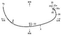
また、図7に示すように、ハウジング4の左側は、車両用ドアミラー1の左側面に回り込むように湾曲形成された湾曲壁部36を有している。湾曲壁部36は、その先端側(後側)に行くほど右側に位置するように形成されており、従って、湾曲壁部36の先端部36aは、湾曲壁部36の基端側(前側)よりも右側に位置することになる。 Further, as shown in FIG. 7, the left side of the
また、ハウジング4の周縁部の端面には、バイザー3の周縁部が嵌合する嵌合溝4aが形成されている。バイザー3の周縁部が嵌合溝4aに嵌合した状態で、バイザー3の周縁部とハウジング4の周縁部とが一体化して内外方向に位置ずれするのが抑制される。 A
図6や図8に示すように、ハウジング4の周縁部には、上記バイザー3の上側係合爪24及び下側係合爪25に対応する部位に、それぞれ、上側延出板部(延出部)34及び下側延出板部(延出部)35が形成されている。上側延出板部34と下側延出板部35とは同じものなので、以下、下側延出板部35について詳細に説明する。 As shown in FIGS. 6 and 8, the peripheral edge of the
本実施形態では、上側延出板部34と下側延出板部35を湾曲壁部36の内面ではなく、湾曲壁部36の先端部36aに形成していることが特徴となっている。すなわち、仮に、湾曲壁部36の内面に上側延出板部34と下側延出板部35を形成するのは、成形型の構造上、困難な場合が多いが、この実施形態のように湾曲壁部36の先端部36aに形成するのであれば、上側延出板部34と下側延出板部35を容易に形成することが可能になる。 The present embodiment is characterized in that the upper extending
図4や図5に示すように、下側延出板部35は、下側係合爪25の突出方向と交差する方向(本実施形態では直交する方向)に右側(ハウジング4の内側)へ延出しており、上下方向に延びている。下側延出板部35は上下方向に長い略矩形状である。下側延出板部35には、下側係合爪25が挿入される係合孔35aが形成されている。この係合孔35aは、下側係合爪25の断面形状に対応して上下方向に長い形状となっている。係合孔35aの大きさは、下側係合爪25の凸部25bが通過可能な大きさである。この係合孔35aの形成により、下側延出板部35は、略矩形の枠状を呈することになる。 As shown in FIGS. 4 and 5, the lower
下側延出板部35の後面には、一対の突起35b,35bが上下方向に間隔をあけて形成されている。 A pair of
また、図8に示すように、ハウジング4の湾曲壁部36の先端部36aには、上側延出板部34及び下側延出板部35の形成部位に、一対の上側リブ44,44及び下側リブ45,45が形成されている。下側リブ45,45は、ハウジング4の本体部内面、具体的には湾曲壁部36内面から突出して下側延出板部35の突起35bが形成された面と反対側(前面)に連なっている。下側リブ45,45は、平面視で略三角形とされている。下側リブ45,45は、上下方向に間隔をあけて配置されている。下側リブ45,45の間隔は、係合孔35aの上下寸法よりも若干広めに設定されており、下側リブ45,45が係合孔35aの開口部分にかからないようにしている。 Further, as shown in FIG. 8, the
下側リブ45,45によって下側延出板部35の上下両側がハウジング4の本体部の内面に支えられることになるので、下側延出板部35の補強効果を十分に得ることができる。 Since both the upper and lower sides of the lower
次に、上記のように構成された車両用ドアミラー1の製造要領について説明する。電動格納ユニット13等をバイザー3に組み付けた後、ハウジング4をバイザー3に取り付ける。このとき、まず、図2に示すように、ハウジング4をバイザー3の前方に配置する。そして、ハウジング4またはバイザー3を相手側に近づけていく。この実施形態では、バイザー3を固定しておき、ハウジング4をバイザー3に近づけていく場合について説明するが、その逆の取付方法も可能である。 Next, a manufacturing procedure of the
図5に示すように、バイザー3の下側係合爪25をハウジング4の下側延出板部35の係合孔35aに対向させた後、ハウジング4を図5中に矢印Yで示すように後方へ移動させていく。このとき、上側係合爪24も上側延出板部34の係合孔に対向させておく。 As shown in FIG. 5, after the lower engaging
ハウジング4の下側延出板部35がバイザー3の下側係合爪25の先端に近接して、下側係合爪25の先端が下側延出板部35の係合孔35aに入っていく。すると、下側係合爪25の傾斜面25dが下側延出板部35の係合孔35aの周縁部に摺接し始め、このことで、下側係合爪25が左側へ弾性変形する。ハウジング4をさらに後側へ移動させると、下側係合爪25の凸部25bが下側延出板部35の係合孔35aを通過する。下側係合爪25の凸部25bが下側延出板部35の係合孔35aを通過した瞬間、下側係合爪25の形状が復元し、図4に示すように凸部25bが下側延出板部35の係合孔35a周縁部に前側から係合する。この係合状態では、下側係合爪25の当接面25cが、下側延出板部35の前面に当接することになる。上側係合爪24も同様にして上側延出板部34に係合する。また、ハウジング4の第1〜第3嵌合片31〜33がそれぞれバイザー3の第1〜第3嵌合孔21〜23に挿入されて嵌合する。 The lower
また、バイザー3の周縁部がハウジング4の嵌合溝4aに嵌合することで、バイザー3の周縁部とハウジング4の周縁部とが一体化する。 Further, the peripheral portion of the
上記のようにしてハウジング4がバイザー3に取り付けられる。ハウジング4がバイザー3に取り付けられた状態で、例えば車両走行時の加振力により、ハウジング4がバイザー3から離脱する方向に力が作用することがある。この場合、下側係合爪25を下側延出板部35の係合孔35aから抜く方向に引っ張り力が作用することになるが、この実施形態では、下側係合爪25の当接面25cと、下側延出板部35の前面とが引っ張り力の作用する方向と直交する方向に延びているので、走行時に作用する程度の引っ張り力では下側係合爪25が下側延出板部35の係合孔35aから抜けることはない。 The
一方、車両用ドアミラー1の電動格納ユニット13等が故障した場合には、ハウジング4をバイザー3から取り外す必要がある。この場合は、作業者がハウジング4を前側に強く引っ張る。このときの力は、下側係合爪25を下側延出板部35の係合孔35aから抜く方向に引っ張り力として作用することになるが、走行時に想定している力よりも大きな力なので、下側係合爪25や下側延出板部35が弾性変形し、下側係合爪25の凸部25bが下側延出板部35の係合孔35aから抜ける。このとき、下側係合爪25は引っ張り力を受ける方向に延びているので、破損しにくくなっている。一方、下側延出板部35は引っ張り力と直交する方向に延びているので、下側延出板部35のうち、特に基端部近傍には屈曲方向の力が作用することなる。このとき、下側延出板部35は下側リブ45,45によってハウジング4の本体部につながっていて補強されているので、下側延出板部35の破損を抑制できる。 On the other hand, when the
以上説明したように、この実施形態にかかる車両用ドアミラーのハウジング取付構造によれば、バイザー3の縁部にハウジング4へ向かって突出する上側係合爪24及び下側係合爪25を形成し、ハウジング4の縁部に、上側係合爪24及び下側係合爪25の突出方向と交差する方向に延出する上側延出板部34及び下側延出板部35を形成し、この延出部34,35に形成した係合孔35aの周縁部に係合爪24,25を係合させるようにしたので、走行時等にハウジング4が不意に脱落するのを防止できる。しかも、修理時にハウジング4を取り外す際には、上側延出板部34及び下側延出板部35が上側リブ44及び下側リブ45によって補強されているので、バイザー3及びハウジング4の破損を招くことなく、これら部品を再利用することができ、もって、修理費用の低廉化を図ることができる。 As described above, according to the vehicle door mirror housing mounting structure according to this embodiment, the upper engaging
また、上側係合爪24及び下側係合爪25をバイザー3に形成し、上側延出板部34及び下側延出板部35をハウジング4に形成したので、力のかかり方等によって、万が一、延出部34,35が破損した場合に、ハウジング4よりは高価なバイザー3を再利用することができ、修理費用が高騰するのを回避できる。 Further, since the upper engaging
また、ハウジング4の本体部内面から突出して上側延出板部34及び下側延出板部35に連なる上側リブ44及び下側リブ45によって上側延出板部34及び下側延出板部35を補強するようにしたので、上側延出板部34及び下側延出板部35の補強効果を十分に得ることができ、破損を未然に防止することができる。 Further, the upper
また、車両用ドアミラー1のデザイン上の要求からハウジング4に湾曲壁部36を形成する場合に、湾曲壁部36の縁部に上側延出板部34及び下側延出板部35を形成することで、型構造の複雑化を招くことはなく、その結果、低コスト化を図ることができる。 Further, when the
本発明は、実施形態に限定されず、その精神または主要な特徴から逸脱することなく、他の色々な形で実施することができる。 The present invention is not limited to the embodiments, and can be implemented in various other forms without departing from the spirit or main features thereof.
例えば、バイザー3における係合爪の形成位置は、バイザー3の縁部であればよいので、上記した位置に限られるものではなく、バイザー3の上側や下側、右側であってもよい。係合爪の個数も任意に設定できる。 For example, the formation position of the engaging claw in the
また、ハウジング4における延出板部の形成位置は、ハウジング4の縁部であればよいので、係合爪と同様に上記した位置に限られるものではない。延出板部の個数も任意に設定できる。 Moreover, since the formation position of the extension board part in the
上述の実施形態はあらゆる点で単なる例示に過ぎず、限定的に解釈してはならない。さらに、特許請求の範囲の均等範囲に属する変形や変更は、全て本発明の範囲内のものである。 The above-described embodiment is merely an example in all respects and should not be interpreted in a limited manner. Further, all modifications and changes belonging to the equivalent scope of the claims are within the scope of the present invention.
以上説明したように、本発明に係る車両用ドアミラーのハウジング取付構造は、例えば、自動車に配設されるドアミラーに適用することができる。 As described above, the vehicle door mirror housing mounting structure according to the present invention can be applied to, for example, a door mirror disposed in an automobile.
1 車両用ドアミラー
2 ミラー
3 バイザー
4 ハウジング
5 ベース
24 上側係合爪
25 下側係合爪
25b 凸部
34 上側延出板部(延出部)
35 下側延出板部(延出部)
35a 係合孔
44 上側リブ(補強部)
45 下側リブ(補強部)DESCRIPTION OF
35 Lower extension plate part (extension part)
45 Lower rib (reinforcement)
Claims (1)
Translated fromJapanese上記ハウジングの本体部は、上記車両用ドアミラーの側面に回り込むように湾曲形成された湾曲壁部を有し、
上記バイザーの縁部には、上記ハウジングへ向かって突出する係合爪が形成され、
上記ハウジングの湾曲壁部の縁部には、上記係合爪に対応する部位に、上記係合爪の突出方向と交差する方向に延出する延出板部と、該延出板部を補強する補強部とが形成され、該延出板部には、上記係合爪が挿入される係合孔が形成され、
上記延出板部における上記係合孔の周縁部の上記バイザー側の面には、上記バイザー側へ向けて突出する突起が形成され、該突起は突出方向基端側へ行くほど上記係合孔に接近するように形成された傾斜面を有し、
上記補強部は、上記ハウジングの上記湾曲壁部内面から突出して上記延出板部における上記突起が形成された面とは反対側の面に連なるリブであり、
上記ハウジングと上記バイザーとの一方を他方に接近する方向に移動させて上記ハウジングを上記バイザーに取り付けた状態で、上記係合爪が上記係合孔に挿入されて該係合孔の周縁部に係合することを特徴とする車両用ドアミラーのハウジング取付構造。In a housing mounting structure for a vehicle door mirror comprising a visor to which a mirror for rearward confirmation is attached and a housing for covering the visor,
The main body portion of the housing has a curved wall portion that is curved so as to go around the side surface of the vehicle door mirror,
An engaging claw that protrudes toward the housing is formed at the edge of the visor.
At the edge of the curved wall portion of the housing, an extension plate portion extending in a direction intersecting the protruding direction of the engagement claw at a portion corresponding to the engagement claw, and the extension plate portion are reinforced A reinforcing portion is formed, and the extending plate portion is formed with an engaging hole into which the engaging claw is inserted,
A protrusion that protrudes toward the visor is formed on the visor-side surface of the peripheral edge of the engagement hole in the extension plate, and the protrusion extends toward the proximal end in the protruding direction. Aninclined surface formed so as to approach
The reinforcing portion is a rib that protrudes from the inner surface of the curved wall portion of the housing and continues to a surface opposite to the surface on which the protrusion is formed in the extension plate portion,
In a state where one of the housing and the visor is moved in a direction approaching the other and the housing is attached to the visor, the engagement claw is inserted into the engagement hole and is inserted into the peripheral portion of the engagement hole. A housing mounting structure for a vehicle door mirror characterized by being engaged.
Priority Applications (1)
| Application Number | Priority Date | Filing Date | Title |
|---|---|---|---|
| JP2012219765AJP6408196B2 (en) | 2012-10-01 | 2012-10-01 | Housing structure for vehicle door mirrors |
Applications Claiming Priority (1)
| Application Number | Priority Date | Filing Date | Title |
|---|---|---|---|
| JP2012219765AJP6408196B2 (en) | 2012-10-01 | 2012-10-01 | Housing structure for vehicle door mirrors |
Publications (2)
| Publication Number | Publication Date |
|---|---|
| JP2014069782A JP2014069782A (en) | 2014-04-21 |
| JP6408196B2true JP6408196B2 (en) | 2018-10-17 |
Family
ID=50745373
Family Applications (1)
| Application Number | Title | Priority Date | Filing Date |
|---|---|---|---|
| JP2012219765AActiveJP6408196B2 (en) | 2012-10-01 | 2012-10-01 | Housing structure for vehicle door mirrors |
Country Status (1)
| Country | Link |
|---|---|
| JP (1) | JP6408196B2 (en) |
Families Citing this family (4)
| Publication number | Priority date | Publication date | Assignee | Title |
|---|---|---|---|---|
| DE102015216145B4 (en) | 2015-08-24 | 2019-01-10 | Mekra Lang Gmbh & Co. Kg | Visual system for vehicles |
| JP6625487B2 (en)* | 2016-06-10 | 2019-12-25 | 株式会社東海理化電機製作所 | Door mirror device and method of manufacturing door mirror device |
| CN110062718B (en)* | 2016-12-14 | 2022-03-01 | 沃尔沃卡车集团 | Mirror assembly for a vehicle |
| CN107719242B (en)* | 2017-09-21 | 2023-08-01 | 宁波爱可森汽车电子有限公司 | Automobile rearview mirror |
Family Cites Families (7)
| Publication number | Priority date | Publication date | Assignee | Title |
|---|---|---|---|---|
| JPS58130866U (en)* | 1982-02-26 | 1983-09-03 | 日本プラスト株式会社 | column cover |
| JPH0615791Y2 (en)* | 1986-09-24 | 1994-04-27 | 本田技研工業株式会社 | Front cover device for motorcycles |
| US5233506A (en)* | 1992-02-21 | 1993-08-03 | Motorola, Inc. | Fastener for housing assembly |
| DE10064647A1 (en)* | 2000-12-22 | 2002-07-11 | Mekra Lang Gmbh & Co Kg | Rearview mirror, in particular for motor vehicles |
| JP4402002B2 (en)* | 2005-04-12 | 2010-01-20 | 株式会社村上開明堂 | Outer mirror |
| JP5501799B2 (en)* | 2010-02-25 | 2014-05-28 | 株式会社村上開明堂 | Vehicle door mirror |
| JP2012066794A (en)* | 2010-09-27 | 2012-04-05 | Tokai Rika Co Ltd | Mirror device for vehicle |
- 2012
- 2012-10-01JPJP2012219765Apatent/JP6408196B2/enactiveActive
Also Published As
| Publication number | Publication date |
|---|---|
| JP2014069782A (en) | 2014-04-21 |
Similar Documents
| Publication | Publication Date | Title |
|---|---|---|
| WO2013146093A1 (en) | Vehicle-mounted camera | |
| JP6408196B2 (en) | Housing structure for vehicle door mirrors | |
| WO2011013195A1 (en) | Bumper mounting structure | |
| JP6670027B2 (en) | Harness holding structure | |
| JP2008012953A (en) | Interior part for automobile | |
| JP5645611B2 (en) | Vehicle camera mounting bracket | |
| JP6076731B2 (en) | Resin nail structure | |
| JP2009262763A (en) | Cowl louver | |
| JP6012301B2 (en) | Mirror base structure | |
| JP4614847B2 (en) | Parts mounting structure | |
| JP2014076699A (en) | Harness assembly structure of door mirror for vehicle | |
| JP5925499B2 (en) | Water stop structure for vehicle doors | |
| JP6076730B2 (en) | Resin nail structure | |
| JP2008230442A (en) | Bumper wire tube mounting structure | |
| JP5867106B2 (en) | Interior member mounting structure and instrument panel structure | |
| JP5412997B2 (en) | Electrical junction box | |
| JP5235524B2 (en) | Cup holder mounting structure | |
| JP6824819B2 (en) | Cowl cover | |
| JP2008025850A (en) | Mounting structure of heat exchanger for vehicle | |
| JP5267172B2 (en) | Vehicle license lamp mounting structure | |
| JP6679923B2 (en) | Vehicle interior parts mounting structure | |
| JP2008143366A (en) | Resin molded product for vehicle and its mounting structure | |
| JP5115811B2 (en) | Mounting structure for vehicle interior materials | |
| JP6310687B2 (en) | Mounting structure for automotive exterior parts and automotive exterior parts | |
| JP6256759B2 (en) | Meter cluster mounting structure |
Legal Events
| Date | Code | Title | Description |
|---|---|---|---|
| A621 | Written request for application examination | Free format text:JAPANESE INTERMEDIATE CODE: A621 Effective date:20150916 | |
| A131 | Notification of reasons for refusal | Free format text:JAPANESE INTERMEDIATE CODE: A131 Effective date:20160426 | |
| A977 | Report on retrieval | Free format text:JAPANESE INTERMEDIATE CODE: A971007 Effective date:20160428 | |
| A521 | Request for written amendment filed | Free format text:JAPANESE INTERMEDIATE CODE: A523 Effective date:20160627 | |
| A131 | Notification of reasons for refusal | Free format text:JAPANESE INTERMEDIATE CODE: A131 Effective date:20161129 | |
| A521 | Request for written amendment filed | Free format text:JAPANESE INTERMEDIATE CODE: A523 Effective date:20170130 | |
| A02 | Decision of refusal | Free format text:JAPANESE INTERMEDIATE CODE: A02 Effective date:20170627 | |
| A521 | Request for written amendment filed | Free format text:JAPANESE INTERMEDIATE CODE: A523 Effective date:20170905 | |
| A911 | Transfer to examiner for re-examination before appeal (zenchi) | Free format text:JAPANESE INTERMEDIATE CODE: A911 Effective date:20170912 | |
| A912 | Re-examination (zenchi) completed and case transferred to appeal board | Free format text:JAPANESE INTERMEDIATE CODE: A912 Effective date:20171013 | |
| A521 | Request for written amendment filed | Free format text:JAPANESE INTERMEDIATE CODE: A523 Effective date:20180629 | |
| A61 | First payment of annual fees (during grant procedure) | Free format text:JAPANESE INTERMEDIATE CODE: A61 Effective date:20180920 | |
| R150 | Certificate of patent or registration of utility model | Ref document number:6408196 Country of ref document:JP Free format text:JAPANESE INTERMEDIATE CODE: R150 | |
| R250 | Receipt of annual fees | Free format text:JAPANESE INTERMEDIATE CODE: R250 | |
| R250 | Receipt of annual fees | Free format text:JAPANESE INTERMEDIATE CODE: R250 | |
| R250 | Receipt of annual fees | Free format text:JAPANESE INTERMEDIATE CODE: R250 | |
| R250 | Receipt of annual fees | Free format text:JAPANESE INTERMEDIATE CODE: R250 | |
| R250 | Receipt of annual fees | Free format text:JAPANESE INTERMEDIATE CODE: R250 |