JP6406529B2 - Improved short message transmission and handover procedures - Google Patents
Improved short message transmission and handover proceduresDownload PDFInfo
- Publication number
- JP6406529B2 JP6406529B2JP2016119552AJP2016119552AJP6406529B2JP 6406529 B2JP6406529 B2JP 6406529B2JP 2016119552 AJP2016119552 AJP 2016119552AJP 2016119552 AJP2016119552 AJP 2016119552AJP 6406529 B2JP6406529 B2JP 6406529B2
- Authority
- JP
- Japan
- Prior art keywords
- data
- user equipment
- sms
- mme
- message
- Prior art date
- Legal status (The legal status is an assumption and is not a legal conclusion. Google has not performed a legal analysis and makes no representation as to the accuracy of the status listed.)
- Active
Links
- 238000000034methodMethods0.000titleclaimsdescription257
- 230000005540biological transmissionEffects0.000titleclaimsdescription152
- 230000001976improved effectEffects0.000titledescription12
- 230000004044responseEffects0.000claimsdescription62
- 238000010295mobile communicationMethods0.000claimsdescription30
- 238000012545processingMethods0.000claimsdescription26
- 230000000977initiatory effectEffects0.000claimsdescription5
- 230000011664signalingEffects0.000description203
- 239000010410layerSubstances0.000description134
- 238000007726management methodMethods0.000description126
- 238000012546transferMethods0.000description92
- 208000034188Stiff person spectrum diseaseDiseases0.000description57
- 230000006870functionEffects0.000description57
- 238000004891communicationMethods0.000description33
- 238000010586diagramMethods0.000description32
- NRZOXEUJFYCPSL-UHFFFAOYSA-N5-(3-chloropropyl)-1-[4-hydroxy-5-(hydroxymethyl)oxolan-2-yl]pyrimidine-2,4-dioneChemical compoundC1C(O)C(CO)OC1N1C(=O)NC(=O)C(CCCCl)=C1NRZOXEUJFYCPSL-UHFFFAOYSA-N0.000description29
- 230000007246mechanismEffects0.000description29
- 230000001960triggered effectEffects0.000description28
- 230000007704transitionEffects0.000description27
- 238000012384transportation and deliveryMethods0.000description27
- 210000004027cellAnatomy0.000description24
- 101001055444Homo sapiens Mediator of RNA polymerase II transcription subunit 20Proteins0.000description21
- 102100026165Mediator of RNA polymerase II transcription subunit 20Human genes0.000description21
- 238000005259measurementMethods0.000description19
- 230000008569processEffects0.000description19
- 108091005487SCARB1Proteins0.000description18
- 102100037118Scavenger receptor class B member 1Human genes0.000description18
- 230000008859changeEffects0.000description18
- 238000002360preparation methodMethods0.000description14
- 230000008901benefitEffects0.000description12
- 102000018059CS domainsHuman genes0.000description11
- 108050007176CS domainsProteins0.000description11
- 230000004913activationEffects0.000description11
- 238000005516engineering processMethods0.000description11
- 230000003111delayed effectEffects0.000description9
- 238000005457optimizationMethods0.000description9
- 238000012423maintenanceMethods0.000description8
- 230000004048modificationEffects0.000description7
- 238000012986modificationMethods0.000description7
- 238000012217deletionMethods0.000description6
- 230000037430deletionEffects0.000description6
- 241000700159RattusSpecies0.000description5
- 239000000872bufferSubstances0.000description5
- 230000006872improvementEffects0.000description5
- 230000000737periodic effectEffects0.000description5
- 238000010561standard procedureMethods0.000description5
- 230000008093supporting effectEffects0.000description5
- 230000009471actionEffects0.000description4
- 210000004754hybrid cellAnatomy0.000description4
- 238000012544monitoring processMethods0.000description3
- 230000009467reductionEffects0.000description3
- 238000011160researchMethods0.000description3
- 230000001360synchronised effectEffects0.000description3
- 239000002699waste materialSubstances0.000description3
- 102100024365Arf-GAP domain and FG repeat-containing protein 1Human genes0.000description2
- 230000009286beneficial effectEffects0.000description2
- 210000004271bone marrow stromal cellAnatomy0.000description2
- 230000002860competitive effectEffects0.000description2
- 230000006835compressionEffects0.000description2
- 238000007906compressionMethods0.000description2
- 239000013256coordination polymerSubstances0.000description2
- 125000000524functional groupChemical group0.000description2
- 230000001965increasing effectEffects0.000description2
- 230000007774longtermEffects0.000description2
- 230000005641tunnelingEffects0.000description2
- 238000010200validation analysisMethods0.000description2
- 102100038470Retinoic acid-induced protein 1Human genes0.000description1
- ATJFFYVFTNAWJD-UHFFFAOYSA-NTinChemical compound[Sn]ATJFFYVFTNAWJD-UHFFFAOYSA-N0.000description1
- 230000003213activating effectEffects0.000description1
- 230000006978adaptationEffects0.000description1
- 239000002131composite materialSubstances0.000description1
- 230000009849deactivationEffects0.000description1
- 230000006837decompressionEffects0.000description1
- 230000001934delayEffects0.000description1
- 238000001514detection methodMethods0.000description1
- 230000000694effectsEffects0.000description1
- 230000005611electricityEffects0.000description1
- 238000005538encapsulationMethods0.000description1
- 230000002708enhancing effectEffects0.000description1
- 230000014509gene expressionEffects0.000description1
- 230000036541healthEffects0.000description1
- 238000010438heat treatmentMethods0.000description1
- 239000012729immediate-release (IR) formulationSubstances0.000description1
- 230000003993interactionEffects0.000description1
- 230000002452interceptive effectEffects0.000description1
- 239000002346layers by functionSubstances0.000description1
- 230000014759maintenance of locationEffects0.000description1
- 239000003550markerSubstances0.000description1
- 230000002028prematureEffects0.000description1
- 238000012913prioritisationMethods0.000description1
- 230000010076replicationEffects0.000description1
- 238000013468resource allocationMethods0.000description1
- 238000012552reviewMethods0.000description1
- 230000011218segmentationEffects0.000description1
- CSRZQMIRAZTJOY-UHFFFAOYSA-Ntrimethylsilyl iodideSubstancesC[Si](C)(C)ICSRZQMIRAZTJOY-UHFFFAOYSA-N0.000description1
- 238000012795verificationMethods0.000description1
- XLYOFNOQVPJJNP-UHFFFAOYSA-NwaterSubstancesOXLYOFNOQVPJJNP-UHFFFAOYSA-N0.000description1
Images


Classifications
- H—ELECTRICITY
- H04—ELECTRIC COMMUNICATION TECHNIQUE
- H04W—WIRELESS COMMUNICATION NETWORKS
- H04W4/00—Services specially adapted for wireless communication networks; Facilities therefor
- H04W4/12—Messaging; Mailboxes; Announcements
- H04W4/14—Short messaging services, e.g. short message services [SMS] or unstructured supplementary service data [USSD]
- H—ELECTRICITY
- H04—ELECTRIC COMMUNICATION TECHNIQUE
- H04W—WIRELESS COMMUNICATION NETWORKS
- H04W4/00—Services specially adapted for wireless communication networks; Facilities therefor
- H04W4/50—Service provisioning or reconfiguring
- H—ELECTRICITY
- H04—ELECTRIC COMMUNICATION TECHNIQUE
- H04W—WIRELESS COMMUNICATION NETWORKS
- H04W4/00—Services specially adapted for wireless communication networks; Facilities therefor
- H04W4/70—Services for machine-to-machine communication [M2M] or machine type communication [MTC]
- H—ELECTRICITY
- H04—ELECTRIC COMMUNICATION TECHNIQUE
- H04W—WIRELESS COMMUNICATION NETWORKS
- H04W68/00—User notification, e.g. alerting and paging, for incoming communication, change of service or the like
- H04W68/005—Transmission of information for alerting of incoming communication
- H—ELECTRICITY
- H04—ELECTRIC COMMUNICATION TECHNIQUE
- H04W—WIRELESS COMMUNICATION NETWORKS
- H04W72/00—Local resource management
- H04W72/20—Control channels or signalling for resource management
- H04W72/23—Control channels or signalling for resource management in the downlink direction of a wireless link, i.e. towards a terminal
- H—ELECTRICITY
- H04—ELECTRIC COMMUNICATION TECHNIQUE
- H04W—WIRELESS COMMUNICATION NETWORKS
- H04W76/00—Connection management
- H04W76/10—Connection setup
- H—ELECTRICITY
- H04—ELECTRIC COMMUNICATION TECHNIQUE
- H04W—WIRELESS COMMUNICATION NETWORKS
- H04W76/00—Connection management
- H04W76/20—Manipulation of established connections
- H04W76/27—Transitions between radio resource control [RRC] states
- H—ELECTRICITY
- H04—ELECTRIC COMMUNICATION TECHNIQUE
- H04W—WIRELESS COMMUNICATION NETWORKS
- H04W76/00—Connection management
- H04W76/30—Connection release
- H04W76/34—Selective release of ongoing connections
- H04W76/36—Selective release of ongoing connections for reassigning the resources associated with the released connections
- H—ELECTRICITY
- H04—ELECTRIC COMMUNICATION TECHNIQUE
- H04W—WIRELESS COMMUNICATION NETWORKS
- H04W76/00—Connection management
- H04W76/30—Connection release
- H04W76/38—Connection release triggered by timers
- H—ELECTRICITY
- H04—ELECTRIC COMMUNICATION TECHNIQUE
- H04W—WIRELESS COMMUNICATION NETWORKS
- H04W36/00—Hand-off or reselection arrangements
- H04W36/0005—Control or signalling for completing the hand-off
- H04W36/0055—Transmission or use of information for re-establishing the radio link
- H04W36/0058—Transmission of hand-off measurement information, e.g. measurement reports
- H—ELECTRICITY
- H04—ELECTRIC COMMUNICATION TECHNIQUE
- H04W—WIRELESS COMMUNICATION NETWORKS
- H04W68/00—User notification, e.g. alerting and paging, for incoming communication, change of service or the like
- H—ELECTRICITY
- H04—ELECTRIC COMMUNICATION TECHNIQUE
- H04W—WIRELESS COMMUNICATION NETWORKS
- H04W76/00—Connection management
- H04W76/10—Connection setup
- H04W76/12—Setup of transport tunnels
- H—ELECTRICITY
- H04—ELECTRIC COMMUNICATION TECHNIQUE
- H04W—WIRELESS COMMUNICATION NETWORKS
- H04W76/00—Connection management
- H04W76/30—Connection release
Landscapes
- Engineering & Computer Science (AREA)
- Computer Networks & Wireless Communication (AREA)
- Signal Processing (AREA)
- Mobile Radio Communication Systems (AREA)
Description
Translated fromJapanese本発明の一態様は、移動ノードのハンドオーバを実行するための方法に関する。さらに、本発明の一態様は、移動ノードと、本発明の方法に関与するその他のエンティティとに関する。 One aspect of the invention relates to a method for performing a handover of a mobile node. Furthermore, an aspect of the invention relates to mobile nodes and other entities involved in the method of the invention.
[ロングタームエボリューション(LTE)]
WCDMA(登録商標)無線アクセス技術をベースとする第3世代の移動通信システム(3G)は、世界中で広範な規模で配備されつつある。この技術を機能強化あるいは発展・進化させるうえでの最初のステップとして、高速下りリンクパケットアクセス(HSDPA)と、エンハンスト上りリンク(高速上りリンクパケットアクセス(HSUPA)とも称する)とが導入され、これにより、極めて競争力の高い無線アクセス技術が提供されている。[Long Term Evolution (LTE)]
Third generation mobile communication systems (3G) based on WCDMA® radio access technology are being deployed on a wide scale around the world. High-speed downlink packet access (HSDPA) and enhanced uplink (also referred to as high-speed uplink packet access (HSUPA)) were introduced as the first steps in enhancing or developing / evolving this technology. Wireless access technologies that are extremely competitive have been provided.
しかしながら、より長期的には、さらに増加しつつあるユーザの需要に備え、新たな無線アクセス技術に対する競争力を備える必要がある。この課題に対応するべく、3GPPは、研究項目としてEvolved UTRAおよびUTRANに着手しており、これらの研究項目は、サービスのプロビジョニングおよびコスト削減の観点でさらに大きな前進を実現するための手段を研究することを目指している。この目標の基礎として、3GPPは、ロング・ターム・エボリューション(LTE)と称される新たな移動通信システムの一連の目標および要件を決定した。LTEは、今後の10年間にわたり、データおよびメディアの高速転送ならびに大容量の音声サポートに関する加入者およびネットワーク事業者のニーズを満足するように設計されている。 However, in the longer term, there is a need to be competitive with new radio access technologies in preparation for increasing user demand. To address this challenge, 3GPP has embarked on Evolved UTRA and UTRAN as research items, which will explore ways to achieve greater progress in terms of service provisioning and cost reduction. I am aiming for that. As the basis for this goal, 3GPP has determined a set of goals and requirements for a new mobile communication system called Long Term Evolution (LTE). LTE is designed to meet the needs of subscribers and network operators for high speed data and media transfers and high volume voice support over the next decade.
[LTEアーキテクチャ]
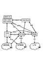
図1は、LTEの全体的なアーキテクチャを示しており、図2は、E−UTRANのアーキテクチャをさらに詳しく示している。[LTE architecture]
FIG. 1 shows the overall architecture of LTE, and FIG. 2 shows the E-UTRAN architecture in more detail.
E−UTRANは、eNodeBから構成されており、eNodeBは、ユーザ機器(UE)に向かうE−UTRAのユーザ・プレーン(PDCP/RLC/MAC/PHY)および制御プレーン(RRC)のプロトコルを終端させる。eNodeB(eNB)は、物理層(PHY)、メディア・アクセス制御(MAC)層、無線リンク制御(RLC)層、およびパケット・データ制御プロトコル(PDCP)層(ユーザプレーンのヘッダ圧縮および暗号化の機能を含んでいる)をホストする。eNodeBは、制御プレーンに対応する無線リソース制御(RRC)機能も提供する。eNodeBは、無線リソース管理、アドミッション制御、スケジューリング、ネゴシエーションされた上りリンクのサービス品質(QoS)の実施、セル情報のブロードキャスト、ユーザ・プレーンデータおよび制御プレーンデータの暗号化/復号、下りリンク/上りリンクのユーザ・プレーン・パケットヘッダの圧縮/復元など、多くの機能を実行する。eNodeBは、X2インターフェースによって互いに接続されている。 E-UTRAN is composed of eNodeB, which terminates E-UTRA user plane (PDCP / RLC / MAC / PHY) and control plane (RRC) protocols towards user equipment (UE). eNodeB (eNB) includes physical layer (PHY), media access control (MAC) layer, radio link control (RLC) layer, and packet data control protocol (PDCP) layer (user plane header compression and encryption functions) Host). The eNodeB also provides a radio resource control (RRC) function corresponding to the control plane. eNodeB performs radio resource management, admission control, scheduling, negotiated uplink quality of service (QoS), cell information broadcast, user plane data and control plane data encryption / decryption, downlink / uplink It performs many functions such as compression / decompression of link user plane packet headers. The eNodeBs are connected to each other by an X2 interface.
さらに、eNodeBは、S1インターフェースによってEPC(Evolved Packet Core)に接続されており、より具体的には、S1−MMEによってMME(Mobility Management Entity:移動管理エンティティ)に接続されており、S1−Uによってサービング・ゲートウェイ(SGW:Serving Gateway)に接続されている。S1インターフェースは、MME/サービング・ゲートウェイとeNodeBとの間の多対多関係をサポートする。 Further, the eNodeB is connected to the EPC (Evolved Packet Core) by the S1 interface, more specifically, to the MME (Mobility Management Entity) by the S1-MME, and by the S1-U. It is connected to a serving gateway (SGW). The S1 interface supports a many-to-many relationship between the MME / serving gateway and the eNodeB.
SGWは、ユーザデータパケットのルーティングおよび転送を行う一方で、eNodeB間のハンドオーバ時にユーザ・プレーンのモビリティアンカ(mobility anchor)としての役割と、LTEとそれ以外の3GPP技術との間のモビリティのためのアンカとしての役割も果たす(S4インターフェースを終端させ、2G/3GシステムとPDN GWとの間でトラフィックを中継する)。SGWは、アイドル状態のユーザ機器に対しては、そのユーザ機器への下りリンクデータが到着したとき下りリンクデータ経路を終端させ、ページングをトリガする。SGWは、ユーザ機器のコンテキスト(例えば、IPベアラ・サービスのパラメータ、ネットワーク内部ルーティング情報)を管理および格納する。さらに、SGWは、合法傍受(lawful interception)の場合にユーザ・トラフィックの複製を実行する。 The SGW routes and forwards user data packets, while serving as a user plane mobility anchor during handover between eNodeBs and for mobility between LTE and other 3GPP technologies It also serves as an anchor (terminates the S4 interface and relays traffic between the 2G / 3G system and the PDN GW). For idle user equipment, the SGW terminates the downlink data path and triggers paging when downlink data arrives for that user equipment. The SGW manages and stores user equipment context (eg, IP bearer service parameters, network internal routing information). In addition, the SGW performs user traffic replication in case of lawful interception.
MMEは、LTEのアクセスネットワークの主要な制御ノードである。MMEは、アイドル・モードのユーザ機器の追跡およびページング手順(再送信を含む)の役割を担う。MMEは、ベアラの有効化/無効化プロセスに関与し、さらには、最初のアタッチ時と、コア・ネットワーク(CN)ノードの再配置を伴うLTE内ハンドオーバ時とに、ユーザ機器のSGWを選択する役割も担う。MMEは、(HSSと対話することによって)ユーザを認証する役割を担う。非アクセス層(NAS:Non-Access Stratum)シグナリングはMMEにおいて終端され、MMEは、一時的なIDを生成してユーザ機器に割り当てる役割も担う。MMEは、サービスプロバイダの公衆陸上移動網(PLMN:Public Land Mobile Network)に入るためのユーザ機器の認証を確認し、ユーザ機器のローミング制限を実施する。MMEは、NASシグナリングの暗号化/完全性保護においてネットワーク内の終端点であり、セキュリティ・キーの管理を行う。シグナリングの合法傍受も、MMEによってサポートされる。さらに、MMEは、LTEのアクセス・ネットワークと2G/3Gのアクセス・ネットワークとの間のモビリティのための制御プレーン機能を提供し、SGSNからのS3インターフェースを終端させる。さらに、MMEは、ローミングするユーザ機器のためのホームHSSに向かうS6aインターフェースを終端させる。 The MME is the main control node of the LTE access network. The MME is responsible for idle mode user equipment tracking and paging procedures (including retransmissions). The MME participates in the bearer activation / deactivation process, and also selects the SGW of the user equipment during the initial attach and during intra-LTE handover with core network (CN) node relocation. Also plays a role. The MME is responsible for authenticating the user (by interacting with the HSS). Non-Access Stratum (NAS) signaling is terminated at the MME, which is also responsible for generating a temporary ID and assigning it to the user equipment. The MME confirms the authentication of the user equipment to enter the service provider's Public Land Mobile Network (PLMN) and enforces roaming restrictions on the user equipment. The MME is a termination point in the network in the encryption / integrity protection of NAS signaling, and manages security keys. Lawful interception of signaling is also supported by the MME. In addition, the MME provides a control plane function for mobility between the LTE access network and the 2G / 3G access network and terminates the S3 interface from the SGSN. Furthermore, the MME terminates the S6a interface towards the home HSS for the roaming user equipment.
移動ノード(MN、またはユーザ機器(UE)とも称される)と無線アクセスとの間の制御シグナリングは、無線リソース制御(RRC)メッセージによって行われる。RRCプロトコルは、レイヤ3に設けられており、UEに固有のシグナリング、アイドル・モードのUEのページング、およびシステム情報のブロードキャストのための機能を提供する。さらに、RRC層は、上位層(例えば、NAS)の制御情報の正確な送信を保証するための再送信機能をサポートする。 Control signaling between the mobile node (also referred to as MN or user equipment (UE)) and radio access is performed by radio resource control (RRC) messages. The RRC protocol is provided in
図3は、例示的なLTEシステムのUEとMMEとの間の制御プレーンのプロトコル・スタックを示す。レイヤ2は、メディア・アクセス制御(MAC)と、無線リンク制御(RLC)と、パケット・データ・コンバージェンス・プロトコル(PDCP:Packet Data Convergence Protocol)とに分けることができ、RLCサブレイヤおよびPDCPサブレイヤは、ネットワーク側のeNodeBにおいて終端される。NAS層は、UEおよびMMEにおいて終端される。RLC層がUEとeNodeBとの間の制御プレーンで提供するサービスは、シグナリング無線ベアラ(SRB)と称される。ユーザ・プレーンにおいては、RLC層によってUEとeNodeBとの間で提供されるサービスは、無線ベアラ(RB)またはデータ無線ベアラ(DRB)と称される。 FIG. 3 shows the protocol stack of the control plane between UE and MME in an exemplary LTE system.
とりわけ、上位層、すなわち非アクセス層(NAS)のメッセージは、ユーザ機器とeNodeBとの間のRRCメッセージによって(例えば、RRC直接情報転送(RRC Direct Information Transfer)メッセージを用いて)搬送される。非アクセス層は、UEとコア・ネットワーク(CN)との間で実行される機能層であり、RRCの上位に位置する。さらに、NASは、回線交換される音声およびデータに関する呼制御(CC)と、パケット交換されるデータに関するセッション管理(SM)と、移動管理(MM)と、パケット交換ドメインおよび回線交換ドメインのショート・メッセージ・サービス(SMS)とを目的とするプロトコルの機能グループである。NAS層が生成する制御メッセージは、NASメッセージと称される。例えば、そのようなメッセージは、移動管理、セッション管理、SMS転送、および呼管理を制御するために使用される。NASメッセージは、NASの転送をサポートするための機能およびプロトコルを含むアクセス層の層(レイヤ3−2−1、RRC、PDCP、RLC、MAC、PHY)を通じて透過的に転送される。 In particular, higher layer, ie non-access layer (NAS) messages are carried by RRC messages between the user equipment and the eNodeB (eg, using RRC Direct Information Transfer messages). The non-access layer is a functional layer that is executed between the UE and the core network (CN), and is located above the RRC. In addition, NAS provides call control (CC) for voice and data that is circuit switched, session management (SM) for data that is packet switched, mobility management (MM), and short switching of packet switched and circuit switched domains. It is a functional group of protocols intended for message service (SMS). A control message generated by the NAS layer is called a NAS message. For example, such messages are used to control mobility management, session management, SMS forwarding, and call management. The NAS message is transparently transferred through the access layer layers (layer 3-2-1, RRC, PDCP, RLC, MAC, PHY) including functions and protocols for supporting NAS transfer.
アクセス層は、アクセス技術に固有のプロトコルの機能グループ、この場合、RRC、PDCP、RLC、MAC、およびPHYである。アクセス層は、無線に関連する情報の転送をサポートするためのプロトコルと、UEとアクセス・ネットワークとの間の無線リソースの使用を調整するためのプロトコルと、アクセス・ネットワークによって提供されるリソースに対するサービング・ネットワーク(serving network)からのアクセスをサポートするプロトコルとを含む。アクセス層は、サービス・アクセス・ポイント(SAP)を通じて非アクセス層(CNに関連するシグナリングおよびサービス)にサービスを提供し、すなわち、UEとコア・ネットワークとの間のアクセス・リンクを提供し、このアクセス・リンクは、1つまたは複数の独立しており同時に存在できるUE−コア・ネットワーク無線アクセス・ベアラ・サービスと、UEおよびコア・ネットワークの上位層エンティティ間のただ1つのシグナリング接続とから構成される。 The access layer is a functional group of protocols specific to the access technology, in this case RRC, PDCP, RLC, MAC, and PHY. The access layer includes a protocol for supporting the transfer of radio related information, a protocol for coordinating the use of radio resources between the UE and the access network, and serving for resources provided by the access network And a protocol that supports access from a serving network. The access layer serves the non-access layer (CN-related signaling and services) through the service access point (SAP), i.e. provides an access link between the UE and the core network, The access link consists of one or more independent and coexisting UE-core network radio access bearer services and a single signaling connection between the UE and higher layer entities of the core network. The
例えば、データを送信しなければならないときに、サービス要求手順によって、非アクセス層シグナリング接続がユーザ機器とMMEとの間で確立された後、ユーザ機器およびMMEは、CONNECTED状態となる。IDLE状態からCONNECTED状態への遷移を開始する最初の上りリンクの非アクセス層メッセージとしては、アタッチ要求、トラッキング・エリア更新要求、サービス要求(もしくは拡張サービス要求)、またはデタッチ要求がある。最初の非アクセス層メッセージを送信するために、ユーザ機器は、まず初めに、無線インターフェース(Uuインターフェース)を介してeNodeBへの無線リソース制御(RRC)接続を確立する。RRC接続を確立する間に、ユーザ機器とeNodeBとが同期され、非アクセス層メッセージを転送するために使用可能なシグナリング無線ベアラ(SRB)が確立される。これについては、後ほど図5を参照しながらより詳細に説明する。 For example, when a data request is to be sent, after the service request procedure establishes a non-access layer signaling connection between the user equipment and the MME, the user equipment and the MME are in the CONNECTED state. The first uplink non-access layer message that starts the transition from the IDLE state to the CONNECTED state includes an attach request, a tracking area update request, a service request (or extended service request), or a detach request. To send the first non-access layer message, the user equipment first establishes a radio resource control (RRC) connection to the eNodeB via the radio interface (Uu interface). During the establishment of the RRC connection, the user equipment and the eNodeB are synchronized and a signaling radio bearer (SRB) is established that can be used to transfer non-access layer messages. This will be described in more detail later with reference to FIG.
図4は、UEと、eNodeBと、サービング・ゲートウェイと、PDNゲートウェイとの間のE−UTRANのユーザ・プレーンのプロトコル・スタックを開示している。プロトコル・スタックは、ネットワーク側のeNodeBにおいて終端されるPDCP(パケット・データ・コンバージェンス・プロトコル)サブレイヤと、RLC(無線リンク制御)サブレイヤと、MAC(メディア・アクセス制御)サブレイヤとから構成されている。UEに関するIPパケットは、EPCに固有のプロトコルでカプセル化され、PDN−GWと、UEに送信するためのeNodeBとの間でトンネリングされる。 FIG. 4 discloses an E-UTRAN user plane protocol stack between a UE, an eNodeB, a serving gateway and a PDN gateway. The protocol stack includes a PDCP (Packet Data Convergence Protocol) sublayer, an RLC (Radio Link Control) sublayer, and a MAC (Media Access Control) sublayer that are terminated in the eNodeB on the network side. The IP packet for the UE is encapsulated with a protocol specific to EPC and tunneled between the PDN-GW and the eNodeB for transmission to the UE.
[EPS移動および接続管理状態]
移動端末(またはユーザ機器、UE)がネットワークにアタッチされるとき、UEは、いわゆるREGISTERED状態になり、すなわち、ネットワークおよびUEにおいて、EPS移動管理(EMM:EPS Mobility Management)コンテキストが確立されており、デフォルトのEPSベアラ・コンテキストが有効化されている。UEが移動通信ネットワークに対してREGISTERED状態である(登録されている)とき、UEは、2つの異なる接続管理状態、すなわち、IDLE状態およびCONNECTED状態になり得る。UEがオフにされているか、またはUEが移動通信ネットワークにアタッチされていないとき、UEは、DEREGISTERED状態である。DEREGISTERED状態においては、EMMコンテキストが存在せず、MMEがUEの位置を把握しておらず、したがって、MMEはUEに到達することができない。[EPS movement and connection management status]
When a mobile terminal (or user equipment, UE) is attached to the network, the UE enters a so-called REGISTERED state, ie, an EPS Mobility Management (EMM) context is established in the network and the UE, The default EPS bearer context is enabled. When the UE is in REGISTERED state (registered) for the mobile communication network, the UE can be in two different connection management states: IDLE state and CONNECTED state. When the UE is turned off or the UE is not attached to the mobile communication network, the UE is in the DEREGISTERED state. In the DEREGISTERED state, there is no EMM context and the MME does not know the location of the UE, so the MME cannot reach the UE.
送信するデータがなく、無線リソースが解放されているが、UEが有効なIP構成を引き続き保持しているとき、UEはIDLE状態にある。IDLE状態のUEは、eNBとの無線の関連付け(すなわち、無線リソース接続、RRC)がなく、したがって、いかなるシグナリング無線ベアラもデータ無線ベアラも存在しない。さらに、UEとネットワークとの間の(例えば、MMEへの)非アクセス層(NAS)シグナリング接続が存在せず、eNBとSGWとの間のS1−U接続も存在しない。 The UE is in the IDLE state when there is no data to send and radio resources are released, but the UE continues to hold a valid IP configuration. A UE in IDLE state does not have a radio association with the eNB (ie, radio resource connection, RRC) and therefore there is no signaling radio bearer or data radio bearer. Furthermore, there is no non-access layer (NAS) signaling connection between the UE and the network (eg to the MME), and there is no S1-U connection between the eNB and the SGW.
UEがCONNECTED状態にあり、UEが、特定の期間、データを送信/受信していないことをネットワーク(通常はeNB)が検出したとき、ネットワーク(通常はeNB)は、無線リソースおよびS1接続を解放すると判断する。その結果、UEは、CONNECTED状態からIDLE状態に遷移する。さらに、MMEは、UEについてのそのMMEの内部状態をIDLEに変更し、eNBへのS1−U接続を解放するようにSGWに通知する。 When the UE is in the CONNECTED state and the network (usually eNB) detects that the UE has not transmitted / received data for a certain period of time, the network (usually eNB) releases radio resources and S1 connection Judge that. As a result, the UE transitions from the CONNECTED state to the IDLE state. Furthermore, the MME changes the internal state of that MME for the UE to IDLE and notifies the SGW to release the S1-U connection to the eNB.
上りリンクまたは下りリンク・データまたはシグナリング(例えば、アクティブ・フラグ(active flag)を伴うTAU手順によるNASシグナリング)をUEとネットワークとの間で交換する必要があるとき、UEおよびMMEは、CONNECTED状態になることとなる。アクティブ・フラグを伴わないTAU手順の場合は、UEが、CONNECTED状態にならずに単一のNASメッセージの送信と受信とをそれぞれ行うことがあり得る。CONNECTED状態に遷移するために、UE、まず初めに、Uuインターフェースを介してeNBへの無線リソース制御(RRC)接続を確立する必要がある。RRC接続を確立する間に、UEとeNBとが同期され、NASメッセージならびに上りリンク・データおよび下りリンク・データを転送するために使用可能なシグナリング無線ベアラ(SRB)およびデータ無線ベアラ(DRB)が確立される。 When uplink or downlink data or signaling (eg, NAS signaling with a TAU procedure with an active flag) needs to be exchanged between the UE and the network, the UE and MME are in the CONNECTED state. Will be. In the case of a TAU procedure without an active flag, the UE may send and receive a single NAS message without going into the CONNECTED state, respectively. In order to transition to the CONNECTED state, the UE first needs to establish a radio resource control (RRC) connection to the eNB via the Uu interface. While establishing the RRC connection, the UE and eNB are synchronized and there are signaling radio bearers (SRBs) and data radio bearers (DRBs) that can be used to transfer NAS messages and uplink and downlink data. Established.
上述のIDLE状態およびCONNECTED状態は、NAS層状態図に関連している。一方、AS層においても、IDLE状態およびCONNECTED状態が定義されている。ASのIDLE状態およびCONNECTED状態は、NASのIDLE状態およびCONNECTED状態と似ているものの、完全には一致しておらず、すなわち、RRC接続が確立される場合、ASの状態はCONNECTEDになり、そうではなく、RRC接続が解放される場合、ASの状態はIDLEになる。ASの状態がCONNECTEDであるとき、NASの状態も必ずCONNECTEDであるとは限らない(例えば、アクティブ・フラグを伴わないTAU手順の場合)。RRC接続の確立、ひいては、AS CONNECTED状態への遷移は、UEのみが「RRCConnectionRequest」メッセージを送信することができるときに、UEによって開始される。UEは、上りリンク・データもしくは上りリンク・シグナリングが利用可能になるか、または下りリンク・データもしくは下りリンク・シグナリングを受信するためにネットワークからページングされるかのどちらかの理由でRRC接続の確立を開始する。以下に、これら2つの場合について詳細を示す。 The IDLE and CONNECTED states described above are related to the NAS layer state diagram. On the other hand, also in the AS layer, an IDLE state and a CONNECTED state are defined. The AS IDLE and CONNECTED states are similar to the NAS IDLE and CONNECTED states, but are not exactly the same, that is, if an RRC connection is established, the AS state will be CONNECTED, and so on. If, instead, the RRC connection is released, the AS state will be IDLE. When the AS state is CONNECTED, the NAS state is not necessarily CONNECTED (for example, in the case of a TAU procedure without an active flag). The establishment of the RRC connection and thus the transition to the AS CONNECTED state is initiated by the UE when only the UE can send the “RRCConnectionRequest” message. The UE establishes an RRC connection because either uplink data or uplink signaling becomes available or is paged from the network to receive downlink data or downlink signaling To start. Details of these two cases will be described below.
− UEは、送信すべき上りリンク・データまたは上りリンクESM NASシグナリングを有する場合、NASサービス要求手順(技術規格TS23.401に記載されており、この技術規格TS23.401は参照により本明細書に援用される)を開始する。UEは、サービス要求メッセージを生成し、対応するRRC接続を確立するようにASをトリガする。「RRCConnectionRequest」メッセージでeNBに送信されるRRC確立理由は、「mo−Data」(移動体発信データ(mobile originated-data)(UEが上りリンク・データを送信したいことを意味する))または「mo−Signaling」(移動体発信シグナリング(mobile originated-signalling)(UEが上りリンク・シグナリングを送信したいことを意味する))に設定される。 -If the UE has uplink data or uplink ESM NAS signaling to transmit, it is described in the NAS service request procedure (as described in technical standard TS23.401, which is hereby incorporated by reference). To be incorporated). The UE generates a service request message and triggers the AS to establish a corresponding RRC connection. The RRC establishment reason sent to the eNB in the “RRCConnectionRequest” message is “mo-Data” (mobile originated-data (meaning that the UE wants to send uplink data)) or “mo -Signaling "(mobile originated-signalling (meaning that the UE wants to send uplink signaling)).
− ネットワークは、UEへの下りリンク・データまたは下りリンクNASシグナリングを有する場合、ページング手順(技術仕様TS36.413およびTS36.331に記載されており、これらの技術規格TS36.413およびTS36.331は参照により本明細書に援用される)を開始する。UEは、ページングを受信するとき、MMEへのサービス要求メッセージを生成することによりNASサービス要求手順を開始する。サービス要求メッセージは、eNBとのRRC接続を確立するようにAS層をトリガする。RRC確立理由は、移動体終端(Mobile Terminated)アクセスを意味する「mt−Access」に設定され、すなわち、移動体終端通信が設定されることとなる。 -If the network has downlink data or downlink NAS signaling to the UE, it is described in the paging procedure (described in technical specifications TS36.413 and TS36.331, these technical standards TS36.413 and TS36.331 are (Incorporated herein by reference). When the UE receives the paging, it initiates the NAS service request procedure by generating a service request message to the MME. The service request message triggers the AS layer to establish an RRC connection with the eNB. The reason for establishing RRC is set to “mt-Access” meaning mobile terminal access, that is, mobile terminal communication is set.
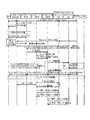
LTE/SAEのNAS移動管理(MM)およびセッション管理(SM)シグナリングは、通常、EMM(EPS MM)およびESM(EPS SM)シグナリングと称される。対照的に、UTRAN/UMTSでは、UEとSGSNとの間のNASシグナリングは、GPRS移動管理(GMM)およびGPRSセッション管理(GSM(登録商標))シグナリングと称される。本発明の一部の態様では、SAE/LTEシステムとUTRAN/UMTSシステムとの間の違いに注意することが重要であるので、GMM/GSM(登録商標)に対するEMM/ESMの用語を導入する。ページング・メッセージ内の「PS」(パケット交換ドメイン)または「CS」(パケット交換ドメイン)の指示に応じて、UEは、NAS接続を確立するために、サービス要求メッセージか、または拡張サービス要求メッセージかのどちらかを送信し得る。以下に、技術仕様TS24.301の8.2.15章による拡張サービス要求メッセージのフォーマットおよび内容を示す。 LTE / SAE NAS mobility management (MM) and session management (SM) signaling is commonly referred to as EMM (EPS MM) and ESM (EPS SM) signaling. In contrast, in UTRAN / UMTS, NAS signaling between UE and SGSN is referred to as GPRS mobility management (GMM) and GPRS session management (GSM) signaling. In some aspects of the invention, it is important to note the difference between SAE / LTE and UTRAN / UMTS systems, so the EMM / ESM terminology for GMM / GSM® is introduced. Depending on the indication of “PS” (packet switched domain) or “CS” (packet switched domain) in the paging message, the UE is either a service request message or an extended service request message to establish a NAS connection. Either can be sent. The format and contents of the extended service request message according to Chapter 8.2.15 of the technical specification TS24.301 are shown below.

RRCプロトコルは、NAS情報の転送をサポートする。加えて、RRC_IDLE状態のUEに関して、RRCは、呼の到着をネットワークから通知することをサポートする。RRC接続制御は、ページング、最初のセキュリティの有効化、シグナリング無線ベアラの確立、およびユーザ・データを搬送する無線ベアラ(データ無線ベアラ)の確立を含む、RRC接続の確立、修正、および解放に関するすべての手順を包含する。
The RRC protocol supports the transfer of NAS information. In addition, for UEs in RRC_IDLE state, RRC supports notification of call arrival from the network. RRC connection control is all about establishing, modifying and releasing RRC connections, including paging, initial security enablement, establishment of signaling radio bearers, and establishment of radio bearers carrying user data (data radio bearers) Including the procedure.
個別RRCメッセージは、シグナリング無線ベアラを介して転送され、これらのシグナリング無線ベアラは、PDCP層およびRLC層を介して論理チャネル(共通制御チャネル(CCCH)(接続の確立中の場合)か、または個別制御チャネル(DCCH)(RRC_CONNECTED状態の場合)かのどちらか)にマッピングされる。システム情報およびページング・メッセージは、論理チャネルであるブロードキャスト制御チャネル(BCCH)およびページング制御チャネル(PCCH)にそれぞれ直接マッピングされる。 Dedicated RRC messages are forwarded via signaling radio bearers, which can be logical channels (common control channel (CCCH) (if connection is being established) via PDCP layer and RLC layer) or dedicated It is mapped to the control channel (DCCH) (in the case of RRC_CONNECTED state). System information and paging messages are mapped directly to the logical channels broadcast control channel (BCCH) and paging control channel (PCCH), respectively.
SRB1とSRB2との主な違いは、eNBにおける優先処理にあり、すなわち、SRB2を介して送信されたRRCメッセージの方が、SRB1を介して送信されたRRCメッセージよりも優先度が低い。通常、NASトランスポート・メッセージはSRB2を介して(上りリンク/下りリンク情報転送メッセージとして)搬送されるが、最初のNASメッセージ、例えば、サービス要求については、SRB1を介して搬送されるRRCメッセージにピギーバックされ得る。SRB1を介したRRCメッセージがRRC層の制御情報を含む一方、SRB2を介したRRCメッセージはNASメッセージに関するトランスポート・メッセージのようなものであることに留意されたい。 The main difference between SRB1 and SRB2 is the priority processing in the eNB, that is, the RRC message transmitted via SRB2 has a lower priority than the RRC message transmitted via SRB1. Normally, NAS transport messages are carried via SRB2 (as uplink / downlink information transfer messages), but for initial NAS messages, eg service requests, RRC messages carried via SRB1 Can be piggybacked. Note that the RRC message via SRB1 contains RRC layer control information, while the RRC message via SRB2 is like a transport message for NAS messages.
SRB0は、CCCHを使用するRRCメッセージのために使用され、SRB1は、DCCHを使用するRRCメッセージ用であり、SRB2は、NAS個別情報(NAS dedicated information)のみを含む、DCCHを使用する(優先度の低い)RRCメッセージ用である。SRB2が確立される前は、SRB1が、NAS個別情報のみを含むRRCメッセージのためにやはり使用される。加えて、SRB1は、NAS個別情報のみを含む優先度の高いRRCメッセージのために使用される。 SRB0 is used for RRC messages using CCCH, SRB1 is for RRC messages using DCCH, and SRB2 uses DCCH including only NAS dedicated information (priority). Low) RRC messages. Before SRB2 is established, SRB1 is also used for RRC messages that contain only NAS specific information. In addition, SRB1 is used for high priority RRC messages that contain only NAS individual information.
DCCHを使用するすべてのRRCメッセージは、(セキュリティが有効化された後は)PDCP層によって完全性を保護され、暗号化される。CCCHを使用するRRCメッセージは、完全性を保護されない。 All RRC messages using DCCH are integrity protected and encrypted by the PDCP layer (after security is enabled). RRC messages using CCCH are not integrity protected.
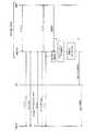
図5は、最初のセキュリティの有効化も含めて、シグナリング無線ベアラSRB0、1、および2のRRC接続確立手順を示すシグナリング図である。RRC接続の確立は、SRB1を確立し、最初の上りリンクNASメッセージを転送することを含む。このNASメッセージが、S1接続の確立をトリガし、通常は、このS1接続の確立によって、E−UTRANがASセキュリティを有効化し、SRB2と、(デフォルトの個別EPSベアラおよび任意の個別EPSベアラに対応する)1つまたは複数のDRBとを確立する後続のステップを引き起こす。 FIG. 5 is a signaling diagram showing the RRC connection establishment procedure of the signaling radio bearers SRB0, 1 and 2 including the first security activation. Establishing the RRC connection includes establishing SRB1 and transferring the initial uplink NAS message. This NAS message triggers the establishment of the S1 connection, which typically allows the E-UTRAN to enable AS security and to support SRB2 (default individual EPS bearer and any individual EPS bearer) Cause) subsequent steps to establish one or more DRBs.
特に、UEの上位層(例えば、NAS)が、(例えば、ページングに応答して)接続の確立をトリガする。UEは、アクセスが禁じられているか否かを調べる。禁じられていない場合、UEの下位層がランダム・アクセス手順を実行し、UEがタイマ(T300として知られている)を開始し、RRCConnectionRequestメッセージを送信する。このメッセージは、初期ID(S−TMSIまたは乱数)および確立理由を含む。 In particular, a higher layer of the UE (eg, NAS) triggers connection establishment (eg, in response to paging). The UE checks whether access is prohibited. If not forbidden, the lower layer of the UE performs a random access procedure, the UE starts a timer (known as T300) and sends an RRCConnectionRequest message. This message includes the initial ID (S-TMSI or random number) and the reason for establishment.
E−UTRANは、接続を受け入れる場合、SRB1を含む初期無線リソース構成を含むRRCConnectionSetupメッセージを返す。それぞれの個々のパラメータをシグナリングする代わりに、E−UTRANは、デフォルト構成、すなわち、パラメータ値がRRCの仕様で規定されている構成を提供するようにUEに命じることができる。 If the E-UTRAN accepts the connection, it returns an RRCConnectionSetup message containing the initial radio resource configuration including SRB1. Instead of signaling each individual parameter, E-UTRAN can instruct the UE to provide a default configuration, i.e., a configuration in which parameter values are specified in the RRC specification.
UEは、RRCConnectionSetupCompleteメッセージを返し、NASメッセージと、(ネットワーク共有をサポートするために使用される)選択されたPLMNの識別子と、上位層が提供する場合には、登録されたMMEの識別子とを含める。最後の2つのパラメータに基づいて、eNodeBは、そのeNodeBがS1接続を確立すべきコア・ネットワーク・ノードを決定する。NASサービス要求または拡張サービス要求メッセージが、RRCConnectionSetupCompleteメッセージに含められる。 The UE returns an RRCConnectionSetupComplete message and includes the NAS message, the selected PLMN identifier (used to support network sharing), and the registered MME identifier if higher layers provide . Based on the last two parameters, the eNodeB determines the core network node with which the eNodeB should establish an S1 connection. A NAS service request or extended service request message is included in the RRCConnectionSetupComplete message.
eNodeBとMMEとの間の初期コンテキスト設定手順は、E−RABコンテキスト、セキュリティ・キー、ハンドオーバ制限リスト、UE無線機能(UE Radio capability)、およびUEセキュリティ機能(UE Security Capabilities)などを含む必要とされる全体的な初期UEコンテキストを確立することを目的としている。この手順は、UEに関連するシグナリングを使用する。 The initial context setup procedure between eNodeB and MME is required to include E-RAB context, security key, handover restriction list, UE Radio capability, UE Security Capability, etc. The goal is to establish an overall initial UE context. This procedure uses signaling associated with the UE.
E−UTRANは、完全性の保護と暗号化とを有効化するためのSecurityModeCommandメッセージを送信する。このメッセージは、完全性を保護されているが、暗号化はされておらず、どのアルゴリズムが使用されることになるのかを示す。 The E-UTRAN sends a SecurityModeCommand message for enabling integrity protection and encryption. This message is integrity protected but not encrypted and indicates which algorithm will be used.
UEは、SecurityModeCommandメッセージの完全性の保護を検証し、この検証が成功する場合、すべての後続のメッセージに完全性の保護と暗号化とを適用するように下位層を構成する(例外として、暗号化は、応答メッセージ、すなわち、SecurityModeComplete(または、SecurityModeFailure)メッセージには適用されない)。 The UE verifies the integrity protection of the SecurityModeCommand message and configures the lower layer to apply integrity protection and encryption to all subsequent messages if this verification is successful (with the exception of encryption Does not apply to response messages, ie, SecurityModeComplete (or SecurityModeFailure) messages.
E−UTRANは、SRB2および1つまたは複数のDRBを確立するために使用される無線リソース構成を含むRRCConnectionReconfigurationメッセージを送信する。さらに、このメッセージは、ピギーバックされるNASメッセージまたは測定の構成などの情報を含む可能性がある。E−UTRANは、SecurityModeCompleteメッセージを受信する前にRRCConnectionReconfigurationメッセージを送信する可能性がある。この場合、E−UTRANは、一方の(または両方の)手順が失敗するとき、接続を解放するべきである。 The E-UTRAN sends an RRCConnectionReconfiguration message containing the radio resource configuration used to establish SRB2 and one or more DRBs. In addition, this message may include information such as NAS messages to be piggybacked or configuration of measurements. The E-UTRAN may send an RRCConnectionReconfiguration message before receiving the SecurityModeComplete message. In this case, the E-UTRAN should release the connection when one (or both) procedure fails.
最後に、UEは、RRCConnectionReconfigurationCompleteメッセージを返す。 Finally, the UE returns an RRCConnectionReconfigurationComplete message.
図5は、RRCConnectionSetupCompleteメッセージおよびS1−APメッセージを使用する、MMEに送信されるNASサービス要求またはNAS拡張サービス要求メッセージの送信も開示する。ユーザ機器は、技術仕様TS24.301の5.6.1節に記載のタイマT3417またはT3417extを開始する。ユーザ機器は、それに応じてアクセス層から指示が受信されるときに、これらのタイマT3417またはT3417extを停止する。例えば、ユーザ機器は、タイマT3417を停止するための、ユーザ・プレーンに関するベアラの確立の指示をアクセス層から受信することになる。タイマT3417extを停止するために、ユーザ機器は、アクセス層からシステム変更の指示を受信することになる。 FIG. 5 also discloses the transmission of a NAS service request or NAS extended service request message sent to the MME using the RRCConnectionSetupComplete message and the S1-AP message. The user equipment starts timer T3417 or T3417ext described in section 5.6.1 of technical specification TS24.301. The user equipment stops these timers T3417 or T3417ext when instructions are received from the access layer accordingly. For example, the user equipment will receive an instruction from the access layer to establish a bearer for the user plane to stop timer T3417. In order to stop timer T3417ext, the user equipment will receive an instruction to change the system from the access layer.
[ページング]
E−UTRANからページング・メッセージを受信するために、アイドル・モードのUEは、ページングを指示するために使用されるRNTI(radio network temporary identity:無線ネットワーク一時ID)値、すなわち、P−RNTIに関してPDCCHチャネルを監視する。UEは、特定のUEに固有の機会にのみPDCCHチャネルを監視する必要がある。それ以外のときは、UEは、DRX(間欠受信)を適用することができ、つまり、UEは、バッテリーの電力を節約するためにそのUEの受信機をオフにすることができる。[paging]
In order to receive a paging message from E-UTRAN, the UE in idle mode may use a radio network temporary identity (RNTI) value used to indicate paging, ie PDCCH for P-RNTI. Monitor the channel. The UE needs to monitor the PDCCH channel only on occasions specific to a particular UE. Otherwise, the UE can apply DRX (intermittent reception), that is, the UE can turn off its receiver to conserve battery power.
アイドル・モードのUEへの接続を再確立するために、MMEは、UEが位置すると予想されるトラッキング・エリアに基づいて、関連するeNodeBにページング要求を配信する。ページング要求メッセージを受信するとき、eNodeBは、そのメッセージで与えられたトラッキング・エリアのうちの1つに含まれるセルの無線インターフェースを介して呼び出しを送信する。通常、UEは、そのUEのSAW−一時移動体加入者ID(S−TMSI:SAW-Temporary Mobile Subscriber Identity)を用いてページングされる。 In order to re-establish the connection to the idle mode UE, the MME delivers a paging request to the associated eNodeB based on the tracking area where the UE is expected to be located. When receiving a paging request message, the eNodeB sends a call over the radio interface of a cell included in one of the tracking areas given in the message. Typically, a UE is paged using its UE's SAW-Temporary Mobile Subscriber Identity (S-TMSI).
MMEからeNodeBに送信されるページング要求メッセージは、技術仕様TS36.413の9.1.6章(これは参照により本明細書に援用される)において以下のように定義されている。 The paging request message sent from the MME to the eNodeB is defined as follows in Chapter 9.1.6 of the technical specification TS 36.413 (which is incorporated herein by reference).
[ショート・メッセージ・サービス(SMS)]
ショート・メッセージ・サービス(SMS)は、GSM(登録商標)の標準化が開始された際は、ユーザ機器の構成と、(例えば、新しい価格または新しい料金プランを知らせる)情報サービスとのためにネットワーク事業者からUEにショート・メッセージを送信するためのメカニズムとなることを目的としていた。後に、ショート・メッセージ・サービスは、蓄積交換型のサービスであるので、ユーザ間のメッセージ(移動体間のテキスト・メッセージ)を搬送するように規定された。最大のSMSのサイズは、当時存在していたシグナリング・フォーマットに合わせるために140バイトまで、または7ビット文字で160文字までと規定されている。より大きな内容は、連結されたSMSで送信可能であり、連結されたSMSにおいては、それぞれのSMSが、セグメンテーション情報を含むユーザ・データ・ヘッダ(UDH)で始まる。UDHはペイロードの一部であるため、セグメントごとに利用可能な文字数はより少なく、7ビット符号化に関して153文字である(160文字ではない)。[Short Message Service (SMS)]
Short Message Service (SMS) is a network business for user equipment configuration and information services (eg to inform new prices or new pricing plans) when GSM standardization begins. It was intended to be a mechanism for transmitting a short message from a person to a UE. Later, since the short message service is a store-and-forward service, it was specified to carry messages between users (text messages between mobiles). The maximum SMS size is defined as 140 bytes to match the signaling format that existed at the time, or up to 160 7-bit characters. Larger content can be sent in concatenated SMS, where each SMS begins with a user data header (UDH) that contains segmentation information. Since UDH is part of the payload, there are fewer characters available per segment, 153 characters for 7-bit encoding (not 160 characters).
図12Aは、移動体通信ネットワークでSMSを転送するためのアーキテクチャを示す。簡単にするために、SM−SC、SMS−GMSC、およびSMS−IWMSCは同じ筐体に実装される可能性があり、SM−SCと称される可能性がある。SMサービスは、回線交換サービスであると考えられ、したがって、SMSは、SM−SCから、回線交換ドメインの移動通信交換局(MSC:Mobile Switching Center)に届けられる。 FIG. 12A shows an architecture for transferring SMS in a mobile communication network. For simplicity, SM-SC, SMS-GMSC, and SMS-IWMSC may be mounted in the same housing and may be referred to as SM-SC. The SM service is considered to be a circuit switching service, and therefore the SMS is delivered from the SM-SC to a mobile switching center (MSC) in the circuit switching domain.
2種類のSMS、すなわち、移動体発信型(MO、ユーザからネットワークに上りリンクで送信される)と、移動体終端型(MT、ネットワークからユーザに下りリンクで送信される)とが規定されている。 Two types of SMS are defined: mobile originating type (MO, transmitted from user to network in uplink) and mobile terminated type (MT, transmitted from network to user in downlink). Yes.
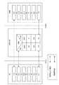
SMS通信のプロトコル階層モデルが、図13に示されており、以降で説明される。この図で使用されている略語「SM」は、「ショート・メッセージ」を意味する。 A protocol layer model for SMS communication is shown in FIG. 13 and will be described below. The abbreviation “SM” used in this figure means “short message”.
図13は、主に、MME/SGSNにおいてSMSをネイティブでサポートするためのプロトコル・スタックを開示していることに留意されたい。言い換えると、「SMSオーバーSGs(SMS over SGs)」を用いたSMS通信のプロトコル階層モデルは示されておらず、図13のプロトコル階層モデルとは異なる。 Note that FIG. 13 mainly discloses a protocol stack for natively supporting SMS in the MME / SGSN. In other words, the protocol layer model of SMS communication using “SMS over SGs” is not shown and is different from the protocol layer model of FIG.
図13において、図示されたSM−SCノードは、図12Aおよび12Bに既に示されたように、機能エンティティであるSMSゲートウェイMSC(SMS−GMSC)およびSMS網間接続MSC(SMS−IWMSC:SMS Interworking MSC)を実装し得る。SMS−GMSCは、例えば、MT−SMSのためにサービングMSC/SGSNに接続するために使用され、すなわち、SMS−GMSCが、MSC/SGSNへのMT TPDUを含むMAPメッセージを送信する(そのようなMAPメッセージは、TPDUを搬送するMAP_MT_FORWARD_SHORT_MESSAGE、または略して「mt−ForwardSM(TPDU)」と称される)。SMS−IWMSCは、例えば、MO−SMSのためにサービングMSC/SGSNに接続するために使用され、すなわち、サービングMSC/SGSNが、SMS−IWMSCへのMO TPDUを含むMAPメッセージ(TPDUを搬送するMAP_MO_FORWARD_SHORT_MESSAGE、または略して「mo−ForwardSM(TPDU)」)を送信する。 In FIG. 13, the SM-SC node shown in FIG. 13 is a functional entity such as an SMS gateway MSC (SMS-GMSC) and an SMS interworking MSC (SMS-IWMSC: SMS Interworking), as already shown in FIGS. 12A and 12B. MSC) may be implemented. The SMS-GMSC is used for example to connect to the serving MSC / SGSN for MT-SMS, i.e. the SMS-GMSC sends a MAP message containing the MT TPDU to the MSC / SGSN (such as The MAP message is referred to as MAP_MT_FORWARD_SHORT_MESSAGE carrying the TPDU, or “mt-ForwardSM (TPDU)” for short). The SMS-IWMSC is used, for example, to connect to the serving MSC / SGSN for MO-SMS, i.e. the MAP message containing the MO TPDU to the SMS-IWMSC (MAP_MO_FORWARD_SHORT_MESSAGE carrying the TPDU). Or “mo-ForwardSM (TPDU)” for short.
図13に示されたSMSプロトコル・エンティティ(例えば、SMRエンティティおよびSMCエンティティ)の実装は、例であることに留意されたい。3GPP以外の将来の1つのシステムまたは複数のシステムにおいては、SMSの機能エンティティの実装は、図示されたSMSの機能エンティティとは異なり、物理ノードで行われる可能性がある。 Note that the implementation of the SMS protocol entities (eg, SMR entity and SMC entity) shown in FIG. 13 is an example. In a future system or systems other than 3GPP, the implementation of the SMS functional entity may be done at the physical node, unlike the SMS functional entity shown.
MT−SMSに関して言えば、SM−SCは、ショート・メッセージ転送層(SM−TL)において送信のためのMT−SMSを準備する。SM−TLメッセージ(TPDU:Transfer Packet Data Unit、転送パケット・データ単位)が、ショート・メッセージ中継層(SM−RL)のショート・メッセージ中継(SMR)エンティティで受信される。SM−RL層のパケット・データ単位(PDU)は、RPDU(中継層PDU)と称される。MT−SMS自体は、RP−DATA RPDUにカプセル化され、対応するACK(acknowledgement)またはエラー・メッセージは、RP−ACKまたはRP−ERRORと称される。結果として、3種類のRPDUが存在することとなる。 With respect to MT-SMS, the SM-SC prepares the MT-SMS for transmission in the short message transfer layer (SM-TL). An SM-TL message (TPDU: Transfer Packet Data Unit) is received at a short message relay (SMR) entity of the short message relay layer (SM-RL). The SM-RL layer packet data unit (PDU) is referred to as RPDU (relay layer PDU). The MT-SMS itself is encapsulated in an RP-DATA RPDU, and the corresponding ACK (acknowledgement) or error message is referred to as RP-ACK or RP-ERROR. As a result, there are three types of RPDUs.
SM−TPプロトコルおよびSM−RPプロトコルは、ネットワーク側のSM−SCおよびMSC/MMEとUEとで対応するように実装される。したがって、中継プロトコルを実装するSMRエンティティは、MSC/MMEおよびUEで実装され、それらの間でRPDUを交換する。 The SM-TP protocol and the SM-RP protocol are implemented so as to correspond to the SM-SC and MSC / MME on the network side and the UE. Thus, SMR entities that implement the relay protocol are implemented at the MSC / MME and UE and exchange RPDUs between them.
回線交換ドメインでのSMSの典型的な送信の場合、SM−SCは、通常、MAP/SS7シグナリングによってMSCに接続され、MSCはSGSN/MMEに接続される。後で説明するように、将来は、さらに、または代替的に、UEがパケット交換ドメインにのみアタッチされるときのSMSの送信のために、SM−SCとSGSN/MMEとの間に直接的なインターフェースが設けられることになる。SS7シグナリングは、SM−SCとSGSN/MMEとの間でTPDUを搬送するために使用されるMAPプロトコルの一部である。実際は、SS7シグナリングは、SM−SCと移動通信交換局(MSC)との間で使用される。SM−SCとSGSNまたはMMEとの間の直接的なインターフェースを介したシグナリングは、MAP/SS7シグナリングか、またはDIAMETERのようなIPに固有のプロトコルかのどちらかに基づく可能性がある。 For a typical transmission of SMS in the circuit switched domain, the SM-SC is usually connected to the MSC by MAP / SS7 signaling, and the MSC is connected to the SGSN / MME. As will be explained later, in the future, in addition or alternatively, a direct connection between the SM-SC and the SGSN / MME for the transmission of SMS when the UE is attached only to the packet switched domain. An interface will be provided. SS7 signaling is part of the MAP protocol used to carry TPDUs between SM-SC and SGSN / MME. In practice, SS7 signaling is used between the SM-SC and the mobile switching center (MSC). Signaling via the direct interface between the SM-SC and SGSN or MME may be based on either MAP / SS7 signaling or an IP specific protocol such as DIAMETER.
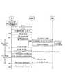
例えば、MAPプロトコルまたはDIAMETERプロトコルでカプセル化されたTPDUがサービングMSC/SGSN/MMEに到着するとき、TPDUは、MSC/SGSN/MMEの内部でSMRエンティティに転送され、さらには、接続管理(CM)サブレイヤにおいてUEおよびSGSN/MMEで終端されるショート・メッセージ制御プロトコル(SM−CP)の一部であるSMCエンティティに転送される。このサブレイヤのプロトコル・エンティティは、SMC(ショート・メッセージ制御)エンティティと称される。このサブレイヤで交換されるPDUは、CPDUと称され、CP−DATA、CP−ACK、およびCP−ERRORのうちの1つである可能性がある。CP−DATA PDUは、SMRエンティティで生成されたRPDUを搬送する。CMサブレイヤは、NAS層の一部であると見なされ得る。CMサブレイヤは、NAS移動管理(MM)サブレイヤのサービスを使用する。3GPP移動通信システムに応じて、MMサブレイヤは、GMM(GPRS MM)またはEMM(EPS MM)と称される。図14は、CPDUおよびRPDUの交換に関する、UEとSM−SCとの間の移動体発信(MO)SMSの例示的なシグナリング・フローを示している。UEは、初め、IDLEモードであるものとする。UEのSMRエンティティがRP−DATA RPDUを生成するとき、SMRエンティティは、SGSN/MMEへのCMシグナリング(すなわち、NAS)接続を確立するようにSMCエンティティをトリガする。 For example, when a TPDU encapsulated with the MAP protocol or DIAMETER protocol arrives at the serving MSC / SGSN / MME, the TPDU is forwarded to the SMR entity within the MSC / SGSN / MME, and also connection management (CM) Forwarded to SMC entities that are part of the Short Message Control Protocol (SM-CP) terminated at the UE and SGSN / MME at the sublayer. This sub-layer protocol entity is referred to as an SMC (Short Message Control) entity. A PDU exchanged in this sublayer is referred to as a CPDU and may be one of CP-DATA, CP-ACK, and CP-ERROR. The CP-DATA PDU carries the RPDU generated by the SMR entity. The CM sublayer may be considered part of the NAS layer. The CM sublayer uses NAS mobility management (MM) sublayer services. Depending on the 3GPP mobile communication system, the MM sublayer is referred to as GMM (GPRS MM) or EMM (EPS MM). FIG. 14 shows an exemplary signaling flow for mobile originating (MO) SMS between the UE and SM-SC for CPDU and RPDU exchange. The UE shall initially be in IDLE mode. When the UE's SMR entity generates an RP-DATA RPDU, the SMR entity triggers the SMC entity to establish a CM signaling (ie, NAS) connection to the SGSN / MME.
UEとMMEとの間のNAS MM接続、およびUEとeNBとの間のRRC接続を確立するために、UEは、NASサービス要求メッセージをMMEに送信する。さらに、UEのNAS層が、RRC接続を確立するようにRRC層に要求する。RRC接続が確立され、サービス要求が送信された後、通常、(1つまたは複数の)データ無線ベアラが確立され、RRC層が、NAS MM接続が確立されていることをNAS層に示す。その後、NAS MM層が、確立されたNAS MM接続についてSMCエンティティに通知し、SMCエンティティが、CPDUを送受信することができる。 In order to establish a NAS MM connection between the UE and the MME and an RRC connection between the UE and the eNB, the UE sends a NAS service request message to the MME. Furthermore, the NAS layer of the UE requests the RRC layer to establish an RRC connection. After the RRC connection is established and the service request is sent, typically the data radio bearer (s) are established and the RRC layer indicates to the NAS layer that a NAS MM connection is established. Thereafter, the NAS MM layer notifies the SMC entity about the established NAS MM connection, and the SMC entity can send and receive CPDUs.
NASシグナリング接続が確立された後、SMCエンティティは、RP−DATAを含むCPDU CP−DATAをSGSN/MMEのSMCエンティティに送信する。SMCエンティティは、RP−DATAをSMRエンティティに転送し、SMRエンティティは、そのRP−DATAをTPDUにカプセル化する。内部転送の後、SGSN/MMEのMAPエンティティが、TPDUでカプセル化されたRP−DATAをmo−ForwardSM(TPDU)としてSM−SCのMAPエンティティに転送する。 After the NAS signaling connection is established, the SMC entity sends CPDU CP-DATA including RP-DATA to the SGSN / MME SMC entity. The SMC entity forwards the RP-DATA to the SMR entity, and the SMR entity encapsulates the RP-DATA in a TPDU. After the internal transfer, the SGSN / MME MAP entity transfers the TPDU encapsulated RP-DATA to the SM-SC MAP entity as mo-ForwardSM (TPDU).
SGSN/MMEのSMCエンティティは、CP−ACKメッセージによってCP−DATAの受信に肯定応答(acknowledge)する。SGSN/MMEのSMCエンティティがSMRエンティティからRPDU(例えば、RP−ACK)を受信するとき、SMCエンティティは、RPDUを含むCP−DATA CPDUを生成し、そのCP−DATA CPDUをUEのSMCエンティティに送信する。(UEとMMEとの両方の)SMRエンティティがもはや送信すべきRPDUを持たないとき、SMRエンティティは、解放要求(Rel Req)を送信することによって、CMシグナリング接続がもはや必要ないことをSMCエンティティに通知する。言い換えると、CM接続の解放(結果としてNAS MM接続を解放し得る)は、SM−RLによって制御される(ただし、エラー状態の場合は例外である)。 The SGSN / MME SMC entity acknowledges receipt of CP-DATA with a CP-ACK message. When the SGSN / MME SMC entity receives an RPDU (eg, RP-ACK) from the SMR entity, the SMC entity generates a CP-DATA CPDU containing the RPDU and sends the CP-DATA CPDU to the UE's SMC entity. To do. When the SMR entity (both UE and MME) no longer has an RPDU to send, the SMR entity informs the SMC entity that the CM signaling connection is no longer needed by sending a release request (Rel Req). Notice. In other words, the release of the CM connection (which can result in the release of the NAS MM connection) is controlled by the SM-RL (with the exception of error conditions).
より詳細に言えば、MME/SGSNのSMCエンティティが、SMRエンティティからのRel Reqと、UEからの最後のCP−ACKとを両方とも受信するとき、SMCエンティティは、NAS MM接続の解放を開始するようにMMエンティティをトリガする。そのために、MME/SGSNのMMエンティティは、eNBにUEコンテキスト解放命令を送信する。その結果、MMEのMMエンティティが、そのUEに関してIDLE状態に遷移する(ただし、そのUEに関するEMMおよびESMコンテキストは維持する)。一方で、eNBは、UEコンテキストを削除し、UEに「RRC接続解放」メッセージを送信する。このメッセージを受信した後、UEのRRC層は、RRC接続が解放されたことをNAS層に示し、NAS層は、IDLE状態に遷移する。 More specifically, when the MMC / SGSN SMC entity receives both the Rel Req from the SMR entity and the last CP-ACK from the UE, the SMC entity initiates the release of the NAS MM connection. Trigger the MM entity as follows: For this purpose, the MM entity of the MME / SGSN sends a UE context release command to the eNB. As a result, the MME's MM entity transitions to the IDLE state for that UE (but maintains the EMM and ESM context for that UE). On the other hand, the eNB deletes the UE context and transmits an “RRC connection release” message to the UE. After receiving this message, the RRC layer of the UE indicates to the NAS layer that the RRC connection has been released, and the NAS layer transitions to the IDLE state.
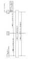
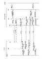
図15に示すように、同様のシグナリング手順が、移動体終端(MT)SMSに関して実行される。この場合、最初のMT−SMSが、SM−SCからUEに転送されるTPDUにカプセル化される。TPDUを搬送するmt−FSMがSGSN/MMEに到着するとき、メッセージは、内部で処理され、SMRエンティティおよびSMCエンティティに転送され、SMCエンティティが、NAS MMシグナリング接続の確立をトリガする。上記目的のために、SGSN/MMEが、UEをページングし、UEは、サービス要求メッセージによって応答してサービス要求手順を開始する。NAS MM接続が確立されると、SGSN/MMEのSMCエンティティが、SMR層のRP−DATAを含むCP−DATA CPDUをUEに送信することができる。UEのSMCエンティティは、CP−DATAメッセージを処理し、RP−DATAをSMRエンティティに転送する。そして、SMCエンティティが、対応するCP−ACKメッセージをSGSN/MMEに送信する。 As shown in FIG. 15, a similar signaling procedure is performed for Mobile Termination (MT) SMS. In this case, the first MT-SMS is encapsulated in a TPDU transferred from the SM-SC to the UE. When the mt-FSM carrying the TPDU arrives at the SGSN / MME, the message is processed internally and forwarded to the SMR entity and the SMC entity, which triggers the establishment of the NAS MM signaling connection. For the above purpose, the SGSN / MME pages the UE, and the UE initiates the service request procedure in response to the service request message. Once the NAS MM connection is established, the SGSN / MME SMC entity can send a CP-DATA CPDU containing the SMR layer RP-DATA to the UE. The UE's SMC entity processes the CP-DATA message and forwards the RP-DATA to the SMR entity. The SMC entity then sends a corresponding CP-ACK message to the SGSN / MME.
UEのSMRエンティティが、RP−ACKメッセージを下層のSMCエンティティに送信し、すると今度は、SMCエンティティが、RP−ACKをCP−DATA CPDUに入れ、そのCP−DATA CPDUをSGSN/MMEのSMCエンティティに送信する。UEおよび/またはMMEのSMRエンティティは、送信すべきRPDUをもはや持たないとき、そのSMRエンティティに対応するSMCエンティティに解放要求メッセージを送信して、CM接続がもはや必要ないことをそのSMCエンティティに知らせる。 The UE's SMR entity sends an RP-ACK message to the underlying SMC entity, which in turn places the RP-ACK in the CP-DATA CPDU and places the CP-DATA CPDU in the SGSN / MME's SMC entity. Send to. When the UE and / or MME SMR entity no longer has an RPDU to send, it sends a release request message to the SMC entity corresponding to that SMR entity to inform the SMC entity that the CM connection is no longer needed. .
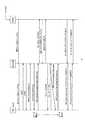
図16は、MO SMSおよびMT SMSに関する図14および図15のシグナリング図をより包括的に示す。特に、上部に、MO SMSに関するシグナリング手順を示し、下部に、MT SMSに関するシグナリング手順を示す。 FIG. 16 shows more comprehensively the signaling diagrams of FIGS. 14 and 15 for MO SMS and MT SMS. In particular, the signaling procedure for MO SMS is shown in the upper part, and the signaling procedure for MT SMS is shown in the lower part.
[パケット交換ドメインにおけるSMS送信]
ほとんどの場合、音声サービスおよびIPサービスを使用する現在のUEは、回線交換サービスとパケット交換サービスとの両方のために移動通信ネットワークにアタッチされる。移動通信ネットワーク(例えば、UTRAN)は、回線交換サービスおよびパケット交換サービスを同時にサポートすることができ、したがって、移動ノードは、やはり、回線交換サービスとパケット交換サービスとのどちらかまたは両方のためにUTRANにアタッチする可能性がある。E−UTRANは、特に、パケット交換サービスのみをサポートするように設計されており、したがって、E−UTRAN内のUEは、回線交換サービスにアタッチすることができない。それにもかかわらず、LTEネットワーク内のUEについても、以下に説明するように、SMSの配信が可能である。[SMS transmission in the packet switching domain]
In most cases, current UEs using voice and IP services are attached to a mobile communication network for both circuit switched and packet switched services. A mobile communication network (e.g., UTRAN) can simultaneously support circuit-switched and packet-switched services, so that a mobile node can still use UTRAN for circuit-switched and / or packet-switched services. There is a possibility to attach to. E-UTRAN is specifically designed to support only packet-switched services, and therefore UEs in E-UTRAN cannot attach to circuit-switched services. Nevertheless, SMS delivery is also possible for UEs in the LTE network, as described below.
3GPPの用語では、UEが「EPS/IMSIアタッチされる(EPS/IMSI attached)」(LTE/SAEシステムの用語として使用される)、または「GPRS/IMSIアタッチされる(GPRS/IMSI attached)」(GSM(登録商標)/UMTSシステムの用語として使用される)と言われる。用語IMSIは、CSサービスに関連し、用語EPSおよびGPRSは、PSサービスに関連する。概して、CSサービスのために使用されるネットワーク・ノードまたはエンティティと、それらに対応するインターフェースとは、CSドメインに属すると言われ、それに応じて、PSサービスのために使用されるネットワーク・ノードまたはエンティティと、それらに対応するインターフェースとは、PSドメインに属すると言われる。 In 3GPP terminology, the UE is “EPS / IMSI attached” (used as LTE / SAE system terminology) or “GPRS / IMSI attached” (GPRS / IMSI attached) ( GSM (R) / UMTS system terminology). The term IMSI relates to CS services, and the terms EPS and GPRS relate to PS services. In general, network nodes or entities used for CS services and their corresponding interfaces are said to belong to the CS domain, and accordingly network nodes or entities used for PS services. And the interface corresponding to them is said to belong to the PS domain.
図12Bは、例示的なシステム・アーキテクチャと、SMS送信に関与するエンティティ間のインターフェースとを開示しており、図12Bに示されたアーキテクチャの方が、図12Aのアーキテクチャよりも新しい。UEがLTEアクセスによってMMEに接続されるとき、SM−SCとMMEとの間でSGdインターフェース(SM−SCとSGSNとの間の既存のインターフェースGdに倣ってSGdと呼ばれる)を介してSMSを直接転送することを可能にする機能である「ネイティブSMS−in−MME(native SMS-in-MME)」が指定されることになる。SM−SCとMMEとの間のSGdインターフェースを設定することは既に合意されているが、そのようなインターフェースは、現在、最終的に規格で定義されていない唯一のインターフェースであり、そのため、名称「SGd」は、図12Bにおいて引用符付きで示してあり、SMS−SCとMMEとの間のインターフェースは、規格によって異なる名称が与えられる可能性がある。 FIG. 12B discloses an exemplary system architecture and the interface between entities involved in SMS transmission, where the architecture shown in FIG. 12B is newer than the architecture of FIG. 12A. When the UE is connected to the MME via LTE access, the SMS directly between the SM-SC and the MME via the SGd interface (called SGd following the existing interface Gd between the SM-SC and SGSN) “Native SMS-in-MME”, which is a function that enables transfer, is designated. Although it has already been agreed to set up an SGd interface between the SM-SC and the MME, such an interface is currently the only interface that is ultimately not defined in the standard, so the name “ “SGd” is shown with quotes in FIG. 12B, and the interface between the SMS-SC and the MME may be given a different name depending on the standard.
SMSの送信は、UEがGERAN(2Gとも称される)またはUTRAN(3Gとも称される)を介してSGSNに登録されるとき、2つの異なる方法、通常は、PSドメイン(すなわち、Gdインターフェースを介したSMS)か、CSドメイン(すなわち、DインターフェースおよびMSCエンティティを介したSMS)かのどちらかで実行され得る。図25〜28は、CSドメインおよび/またはPSドメインを含む、SMS配信のためのあり得るさまざまな経路を大まかに示す。図27および28は、UEがGERANおよびUTRANを介してSGSNに登録される特定の場合を示す。 The transmission of SMS can be done in two different ways, usually the PS domain (ie Gd interface) when the UE registers with the SGSN via GERAN (also called 2G) or UTRAN (also called 3G). Via SMS) or CS domain (ie SMS via D interface and MSC entity). Figures 25-28 generally illustrate various possible routes for SMS delivery, including CS and / or PS domains. Figures 27 and 28 show the specific case where the UE is registered with the SGSN via GERAN and UTRAN.
PSドメインのSMS(SMSオーバーGdインターフェース(SMS over Gd interface)とも称される):SGSNが、Gdインターフェースを介してSMS−SCとSGSNとの間でネイティブのSMS送信が可能となるように、SM−RPプロトコルおよびSM−CPプロトコルのSMSプロトコル・スタックを実装する。この文脈においては、ネイティブのSMS送信とは、UEがアタッチされているサービング・ノードが、RP−DATA PDUおよびCP−DATA PDUを形成するためのSMSプロトコルであるSM−RPおよびSM−CPをサポートすることを意味する。それに対応して、SMS−SCは、SM−TPプロトコルを使用してGdインターフェースを介してSGSNにSMSを送信し、すると今度は、SGSNが、SM−CPプロトコルおよびSM−RPプロトコルを用いてGbまたはIupsインターフェースを介してそれぞれGERANまたはUTRANアクセスのUEにSMSを転送することができる。これが、図27に示されており、「ネイティブSMS−in−SGSN(native-SMS-in-SGSN)」配信と称される可能性がある。さらに、図27は、SMS−SCからMT SMSを受信したときに、UEがSGSNによってどのようにページングされるかを破線で示している。 PS domain SMS (also referred to as SMS over Gd interface): the SMSN allows the native SMS transmission between the SMS-SC and the SGSN over the Gd interface. -Implement the SMS protocol stack of the RP and SM-CP protocols. In this context, native SMS transmission supports SM-RP and SM-CP, which are SMS protocols for the serving node to which the UE is attached to form RP-DATA PDU and CP-DATA PDU. It means to do. Correspondingly, the SMS-SC sends an SMS to the SGSN over the Gd interface using the SM-TP protocol, which in turn, the SGSN uses the SM-CP and SM-RP protocols to Alternatively, SMS can be transferred to UEs with GERAN or UTRAN access respectively via the Iups interface. This is illustrated in FIG. 27 and may be referred to as “native SMS-in-SGSN” delivery. Furthermore, FIG. 27 shows in broken lines how the UE is paged by the SGSN when it receives MT SMS from the SMS-SC.
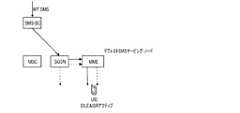
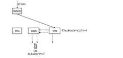
移動ノードがLTEネットワーク内にあるとき、SMSは、「新たな」SGdインターフェースを介してSMS−SCとMMEとの間で送信され、SM−CPプロトコルおよびSM−RPプロトコルを用いてS1インターフェースを介してMMEからUEに送信され得る。これが、図26に示されており、「ネイティブSMS−in−MME」配信と称される可能性がある。さらに、図26は、MMEでSMS−SCからMT SMSを受信したときに、UEがMMEによってどのようにページングされるかを破線で示している。 When the mobile node is in the LTE network, SMS is sent between the SMS-SC and MME via the “new” SGd interface and via the S1 interface using the SM-CP and SM-RP protocols. From the MME to the UE. This is illustrated in FIG. 26 and may be referred to as “native SMS-in-MME” delivery. Furthermore, FIG. 26 shows in broken lines how the UE is paged by the MME when it receives MT SMS from the SMS-SC at the MME.
その結果、SMSは、図26および27においてはPSドメインのエンティティのみを使用してコア・ネットワーク内で配信されており、CSドメインは使用されていない。そのような場合、UEはMSISDN番号を持っている必要がないことに留意されたい。したがって、MO SMSおよびMT SMSは、MSISDN識別子が存在することなしにコア・ネットワーク内でルーティング(および場合によっては格納)可能であり、その代わりに、別のUE識別子、例えばIMSIが使用され得る。 As a result, SMS is distributed within the core network using only PS domain entities in FIGS. 26 and 27, and the CS domain is not used. Note that in such cases, the UE does not need to have an MSISDN number. Therefore, MO SMS and MT SMS can be routed (and possibly stored) in the core network without the presence of an MSISDN identifier, instead another UE identifier, eg IMSI, can be used.
最近の3GPPの活動で、SGSNが、NAS GMM受容メッセージで「SMSサポート(SMS supported)」フラグを送信することによって「PSのみ(PS only)」のSMSをサポートすることをUEに通知することが規定された。これは主にMO SMSの送信に関して実行され、UEは、MO SMSがSGSNサービング・ノードを介して送信され得る(すなわち、SMS送信のためにMSCに接続する必要がない)ことが分かっている。さらに、SGSNからのこのNAS GMMの「SMSサポート」の指示は、MT SMSがSGSNからUEに直接送信され得ることをUEに示す。さらに、PSドメインのサービスのみを受け、NASをベースとするSMSに対応したUEは、アタッチ/RAU複合(combined Attach/RAU)手順の間に、SGSNに「SMSのみ(SMS-only)」と通知することに留意されたい。 In recent 3GPP activities, the SGSN may inform the UE that it supports “PS only” SMS by sending the “SMS supported” flag in the NAS GMM Accept message. It was prescribed. This is mainly done for MO SMS transmission, and the UE knows that MO SMS can be transmitted via the SGSN serving node (ie, it does not need to connect to the MSC for SMS transmission). Further, this NAS GMM “SMS support” indication from the SGSN indicates to the UE that MT SMS may be sent directly from the SGSN to the UE. Furthermore, a UE that receives only PS domain services and supports NAS-based SMS notifies the SGSN of “SMS-only” during the combined Attach / RAU procedure. Please note that.
CSドメインのSMS:概して、CSドメインにおけるSMSの転送は、MSCサーバを用いて実現可能であり、そのとき、MSCサーバは、それぞれUTRANまたはGERANでUEにSMSを送信することができる。これが、図28に示されており、SMSは、CSドメインのみで配信され、したがって、「SMSオーバーCS(SMS-over-CS)」と称される可能性がある。SMS−SCは、MT SMSを受信するとき、そのMT SMSを、Dインターフェースを介してMSCサーバに転送する。UEは、ページングを受信するとき、CSドメインに切り替わることができる(すなわち、UEは、MSCに登録する)。そのとき、MSCサーバは、SMS CP/RPプロトコルによってSMSをUEに直接送信することができる(図28参照)。さらに、図28は、MT SMSがMSCに到着し、UEがSGSNに登録されているときのあり得るページング経路を示す。ページングは、したがって、MSCがページング・メッセージを生成し、UTRANネットワーク内にブロードキャストされるようにそのページング・メッセージをSGSNに転送するように、Gsインターフェースを介して行われ得る。代替的に、MSCが、GERANおよびUTRANで直接ページングを行う可能性がある。SMSの転送が、MSCからSGSNにGsインターフェースを介して行われることはあり得ないことに留意されたい。 SMS in the CS domain: In general, the transfer of SMS in the CS domain can be realized using an MSC server, which can then send an SMS to the UE in UTRAN or GERAN, respectively. This is illustrated in FIG. 28, where SMS is delivered only in the CS domain and may therefore be referred to as “SMS-over-CS”. When the SMS-SC receives the MT SMS, it forwards the MT SMS to the MSC server via the D interface. When the UE receives the paging, it can switch to the CS domain (ie, the UE registers with the MSC). At that time, the MSC server can directly send the SMS to the UE by the SMS CP / RP protocol (see FIG. 28). Further, FIG. 28 shows a possible paging path when MT SMS arrives at the MSC and the UE is registered with the SGSN. Paging can therefore be done via the Gs interface so that the MSC generates a paging message and forwards the paging message to the SGSN for broadcast in the UTRAN network. Alternatively, the MSC may perform direct paging with GERAN and UTRAN. Note that an SMS transfer cannot be done from the MSC to the SGSN via the Gs interface.
PS+CS複合ドメインのSMS:SMSが、MSCサーバを経由し、MAPプロトコルを使用してSGsインターフェースを介してMMEと交換される場合も、MSCサーバ(ひいては回線交換ドメイン)が関与する。この場合、LTEネットワーク内に位置するUEは、SMSを転送するSM−CP PDUをカプセル化するNASプロトコルを使用してS1インターフェースを介してMMEからSMSを受信する。図25は、このSMS配信を示しており、このSMS配信は「SMSオーバーSGs」と称される可能性がある。さらに、図25は、破線によりページングを示しており、SMS−SCからMT SMSを受信すると、MSCは、SGsインターフェースを介してMMEにページングを送信する。すると今度は、MMEが、そのMMEのネットワーク内でUEをページングする。 PS + CS composite domain SMS: The MSC server (and thus the circuit switched domain) is also involved when the SMS is exchanged with the MME via the SGs interface via the MSC server and using the MAP protocol. In this case, the UE located in the LTE network receives the SMS from the MME via the S1 interface using the NAS protocol that encapsulates the SM-CP PDU that forwards the SMS. FIG. 25 illustrates this SMS delivery, which may be referred to as “SMS over SGs”. Further, FIG. 25 shows paging by a broken line. Upon receiving MT SMS from the SMS-SC, the MSC sends paging to the MME via the SGs interface. This time, the MME then pages the UE within the MME's network.
MMEに登録されたUEに関しては、SGsインターフェースを介したSMSの交換(すなわち、規格のリリース9で規定された、MSCからの「SMSオーバーSGs」)と、(規格のリリース11で規定された、SM−SCから直接の)「ネイティブSMS−in−MME」機能を使用することとの間に違いがないことに留意されたい。 For UEs registered with the MME, the exchange of SMS over the SGs interface (ie, “SMS over SGs” from the MSC, as specified in standard release 9), and (as specified in
MMEは、SMC機能およびSMR機能を含むSMS手順と、「SMSのみ」の場合の通常のEPS/IMSI複合(combined EPS/IMSI)手順とをサポートすることになる。加えて、MMEは、
・ ブロードキャストされないLAI(ロケーション・エリアID)をUEに提供し(このLAIは、正しくCS+PS複合アタッチされる(combined CS+PS attached)ためにUEで必要とされる)、
・ アタッチ/TAU受容メッセージで、IMSIアタッチが「SMSのみ」のためであることを示し、
・ MMEがMSCとのSGs関連付けを確立することを必要とせずにSMSを転送することができることをHSSに通知する。The MME will support SMS procedures including SMC and SMR functions and the normal EPS / IMSI combined (combined EPS / IMSI) procedure in the case of “SMS only”. In addition, MME
Provide the UE with a non-broadcast LAI (Location Area ID) (this LAI is required by the UE to be properly CS + PS attached)
In the attach / TAU accept message, indicate that the IMSI attach is for "SMS only"
Inform the HSS that the MME can forward the SMS without requiring the SGs association with the MSC to be established.
PSのみでアタッチされたUEが2G/3G(すなわち、GERAN/UTRAN)アクセスを介してSGSNに接続されているときは、SMS送信に関して以下の規定がある。 When a UE attached with PS only is connected to SGSN via 2G / 3G (ie GERAN / UTRAN) access, there are the following provisions for SMS transmission:
・ SGSNとHSS/HLRとの間のインターフェースに関し、
○ PSドメインのNASを介したSMSサービスのサポートは任意であり、HSSへの加入、SGSNのサポート、およびUEの指示に依存する。Regarding the interface between SGSN and HSS / HLR,
O Support for SMS services via PS domain NAS is optional and depends on HSS subscription, SGSN support, and UE indication.
○ 加入者データがCSへの加入を含まない場合、HSSは、SGSNに「PSのみ強制実施(PS-only-enforced)」を指示し、SGSNは、GMM複合(combined GMM)手順を実行せず、Gs関連付けを確立しない。 O If the subscriber data does not include a CS subscription, the HSS instructs the SGSN “PS-only-enforced” and the SGSN does not perform the combined GMM procedure. Do not establish Gs association.
○ HSSがSGSNに「PSのみ有効(PS-only-enabled)」を指示し、SGSNがNASをベースとするSMSをサポートする場合、SGSNは、Gs関連付けを確立しない。 O If the HSS instructs the SGSN “PS-only-enabled” and the SGSN supports NAS-based SMS, the SGSN does not establish a Gs association.
・ SGSNとUEとの間のインターフェースに関し、
○ PSドメインのサービスのみを受けており、NASをベースとするSMSに対応しているUEは、アタッチ/RAU複合手順の間にSGSNに「SMSのみ」と通知する。Regarding the interface between SGSN and UE,
O A UE that is receiving only PS domain services and that supports NAS-based SMS notifies the SGSN "SMS only" during the combined attach / RAU procedure.
○ SGSNは、アタッチ/RAU手順の間にUEに「SMSサポート」と通知する。PSドメインのサービスのみを受けており、NASをベースとするSMSに対応しているUEは、「SMSサポート」を受信するとき、IMSIアタッチ/LAU手順を実行すべきでない。 O The SGSN notifies the UE of "SMS support" during the attach / RAU procedure. A UE receiving only PS domain services and supporting NAS-based SMS should not perform the IMSI attach / LAU procedure when receiving "SMS support".
要約すると、どのエンティティがネイティブのSMS交換機能をサポートするかに関して4つの異なるケースが特定可能であり、異なるノードに実装されたSMS機能と、実際に使用されるネットワーク構成とに依存して、SMSがネットワーク・アーキテクチャの中で送信され得る方法に影響を与える。 In summary, four different cases can be identified regarding which entities support native SMS exchange functions, depending on the SMS functions implemented in different nodes and the actual network configuration used, the SMS Affects the way that can be transmitted in the network architecture.
図25〜28は、どの場合にどのSMSの交換経路を取り得るのかを示すために、異なるケースの印が付されている。例えば、図25による交換経路は、実際にはすべてのケースであり得る。SGSNおよびMMEがSM−CP/RPプロトコルを実装するケースAでは、図25〜28の経路のすべてがあり得る。実際にどの経路が使用されるかは、例えば、ネットワーク構成と、UEの位置とに依存する。より詳細に言えば、HSS/HLRが、SMS配信のためにUEにサービスを提供することになるエンティティ、例えば、MSC、MME、またはSGSNを格納する。それに対応して、SMSがSMS−SCに到着するとき、SMS−SCは、HSS/HLRと通信して、移動ノードのためのSMSサービング・ノードを知る。したがって、UEがLTEネットワーク内にあると仮定して、MMEがネイティブのSMS交換に対応している(すなわち、対応するSM−CP/RPプロトコルを備える)可能性があっても、ネットワーク構成は、HSSがSMS−SCにMSCについて通知するようになっており、この場合、MMEのこのネイティブのSMS機能は活用されず、したがって、SMSは、SGdインターフェースを介してMMEに直接送信されない。その代わりに、SMS−SCは、UEに関連するMSCのアドレスを知り、上述のように(図25参照)、SMSを、さらに転送されるように、Dインターフェースを介してMSCに送信する。 FIGS. 25-28 are marked with different cases to show which SMS exchange paths can be taken in which case. For example, the exchange path according to FIG. 25 may actually be all cases. In case A where the SGSN and MME implement the SM-CP / RP protocol, all of the paths of FIGS. Which route is actually used depends on, for example, the network configuration and the location of the UE. More specifically, the HSS / HLR stores an entity, eg, MSC, MME, or SGSN, that will serve the UE for SMS delivery. Correspondingly, when the SMS arrives at the SMS-SC, the SMS-SC communicates with the HSS / HLR to know the SMS serving node for the mobile node. Thus, assuming that the UE is in an LTE network, even though the MME may support a native SMS exchange (ie, with a corresponding SM-CP / RP protocol), the network configuration is The HSS will inform the SMS-SC about the MSC, in which case this native SMS functionality of the MME will not be exploited and therefore the SMS will not be sent directly to the MME via the SGd interface. Instead, the SMS-SC knows the address of the MSC associated with the UE and sends the SMS to the MSC via the D interface for further forwarding as described above (see FIG. 25).
同様に、SGSNがネイティブでSMSを送信することができるにもかかわらず、SMS−SCは、UEがUTRAN内にあるとき、やはり、代わりにMSCサーバを使用するようにHSS/HLRによって命令される可能性がある(図28参照)。 Similarly, even though the SGSN can send SMS natively, the SMS-SC is still instructed by the HSS / HLR to use the MSC server instead when the UE is in UTRAN There is a possibility (see FIG. 28).
4つのケースとあり得るSMS配信経路とは、以下のようにまとめられる。 The four cases and possible SMS delivery routes are summarized as follows.
ケースA:(LTEまたは2G/3Gで)UEがSGSNまたはMMEに登録されているとき、PSドメインで(MSCの関与なしに)ネイティブのSMS送信が可能である。このケースAでは、UEは、図26および27によれば、SGSNまたはMMEに登録されているとき、SMSをネイティブで送受信することができる。しかし、ネットワーク構成がSMS−SCにCSドメインを関与させるように要求する場合は、図25および図28によるSMS配信の経路もあり得る。 Case A: When the UE is registered with SGSN or MME (in LTE or 2G / 3G), native SMS transmission is possible in PS domain (without MSC involvement). In this case A, according to FIGS. 26 and 27, the UE can send and receive SMS natively when registered with SGSN or MME. However, if the network configuration requires the SMS-SC to involve the CS domain, there may be a route for SMS delivery according to FIGS.
以下の状況においては、問題または不確実性が生じる可能性がある。 Problems or uncertainties can arise in the following situations:
1)GERAN/UTRANとLTEとの間のハンドオーバ中。SMS PDUが転送される方法が規定されていない。 1) During handover between GERAN / UTRAN and LTE. The method by which SMS PDUs are transferred is not specified.
2)ISRが有効化されているときは、SM−SCがSMSのルーティングのための単一のエンティティを知る必要がある(SM−SCがHLR/HSSにルーティング情報を問い合わせる)ときにMT SMSのルーティングが明らかにされるべきである。 2) When ISR is enabled, the SM-SC needs to know a single entity for SMS routing (SM-SC queries the HLR / HSS for routing information) Routing should be clarified.
ケースB:MMEを介したネイティブのSMS送信が可能である。SGSNがネイティブのSMS送信をサポートしないので、図27による経路は取り得ない。その代わりに、UEがUTRANネットワーク内にあるとき、SMSは、図28の経路によって交換される必要がある。それに対応して、このケースBでは、UEがUTRAN内にあるときは、CSドメインを介してのみ、SMSの転送ができる。 Case B: Native SMS transmission via MME is possible. Since SGSN does not support native SMS transmission, the path according to FIG. 27 is not possible. Instead, when the UE is in the UTRAN network, SMS needs to be exchanged by the path of FIG. Correspondingly, in this case B, when the UE is in UTRAN, SMS can only be transferred via the CS domain.
ネットワーク事業者がCSドメインのエンティティ、例えばMSCを使用することを避けたい場合、問題または不確実性が生じる可能性がある。UEがGERANアクセスおよびUTRANアクセスを介して接続されているときに、SMS PDUがUEに/UEから配信される方法が明らかでない。ケースC:SGSNを介したネイティブのSMS送信が可能である。MMEが、ネイティブのSMS送信をサポートせず、そのため、ケースCに関しては、図26による経路の交換が不可能である。その代わりに、LTEネットワーク内にあるとき、UEは、MSCサーバが関与する図25の経路によってSMSを受信する必要がある。 Problems or uncertainties can arise if a network operator wishes to avoid using CS domain entities such as MSCs. It is not clear how SMS PDUs are delivered to / from the UE when the UE is connected via GERAN and UTRAN access. Case C: Native SMS transmission via SGSN is possible. The MME does not support native SMS transmission, so for case C, the path exchange according to FIG. 26 is not possible. Instead, when in the LTE network, the UE needs to receive the SMS via the path of FIG. 25 involving the MSC server.
ネットワーク事業者がCSドメインのエンティティ、例えばMSCを使用することを避けたい場合、問題または不確実性が生じる可能性がある。UEがLTEアクセスを介して接続されているときに、SMS PDUがUEに/UEから配信される方法が明らかでない。 Problems or uncertainties can arise if a network operator wishes to avoid using CS domain entities such as MSCs. It is not clear how SMS PDUs are delivered to / from the UE when the UE is connected via LTE access.
ケースD:SGSNもMMEもネイティブのSMS機能をサポートしないとき、図26および27による交換は不可能である。それに対応して、MSCサーバが、図25および28に示すように、UEへのSMSの転送に常に関与する。このケースDは、PSドメインにおいていかなるSMS送信もできないので、本出願にとってそれほど重要ではない。 Case D: When neither SGSN nor MME support native SMS functionality, the exchange according to FIGS. 26 and 27 is not possible. Correspondingly, the MSC server is always involved in forwarding the SMS to the UE, as shown in FIGS. This case D is not very important for the present application because no SMS transmission is possible in the PS domain.
SMSは、上で説明し、図25および28に図示したように、通常、移動通信交換局(MSC)が関与する回線交換サービスであると考えられているにもかかわらず、最近、3GPPの標準化では、PSサービスのみ(PSのみ)に加入および/またはアタッチされているUEのためのSMSの送信を実装することが決定された。 SMS has recently been standardized for 3GPP, despite being considered a circuit-switched service involving a mobile switching center (MSC), as described above and illustrated in FIGS. 25 and 28. Has decided to implement sending SMS for UEs subscribed to and / or attached to PS service only (PS only).
上に示されたように、MSCサーバは、図25および28によるSMS送信に関与する。ケースBの場合、UEがUTRAN内にあるとき、MSCサーバなしにSMSを送信することはできない。それに対応して、ケースCにおいて、UEがLTE内にあるときに、MSCサーバなしにSMSを送信することはやはり不可能である。しかし、このことは、MSCがもはや関与しない、UEのためのPSのみのSMSの交換を実現するという目標に反する。 As indicated above, the MSC server is responsible for the SMS transmission according to FIGS. For Case B, SMS cannot be sent without the MSC server when the UE is in UTRAN. Correspondingly, in case C, it is still impossible to send an SMS without an MSC server when the UE is in LTE. However, this is contrary to the goal of realizing PS-only SMS exchange for the UE, where the MSC is no longer involved.
[アイドル状態シグナリング削減(ISR:Idle state signaling reduction)機能]
3GPPは、LTEアクセスとUTRAN/GERANアクセスとの間のIDLEモードでの移動、すなわち、UEが、サービング・ノードであるMMEとSGSNとの間を移動する場合の最適化を定義した。この最適化は、IDLEモード・シグナリング削減(略してISR)と称されており、UEが異なる無線アクセス技術(RAT)の間を切り替えるときにいかなるシグナリングも開始しなくて済むようにする。以下で、ISR機能の概要を簡単に紹介するが、ISRのより詳細な検討については3GPP TS23.401 v11.1.0の付録Jを参照することができ、この文献は、3GPPのサーバからダウンロード可能であり、参照により本明細書に援用される。[Idle state signaling reduction (ISR) function]
3GPP defined the movement in the IDLE mode between LTE access and UTRAN / GERAN access, ie the optimization when the UE moves between the serving node MME and SGSN. This optimization, referred to as IDLE mode signaling reduction (ISR for short), ensures that no signaling needs to be initiated when the UE switches between different radio access technologies (RAT). In the following, an overview of the ISR function will be introduced briefly, but for a more detailed review of ISR, you can refer to Appendix J of 3GPP TS23.401 v11.1.0, which is downloaded from the 3GPP server. Yes, and is hereby incorporated by reference.
ISRは、一緒に運用されているE−UTRAN(LTE)とGERAN/UTRANとの間でUEが再選択を行うことによって引き起こされるTAU手順およびRAU手順の頻度を少なくすることを目的としている。特に、UEとネットワークとの間の更新シグナリングが削減されるが、ネットワーク内部のシグナリングも削減される。 The ISR aims to reduce the frequency of TAU and RAU procedures caused by UE reselection between E-UTRAN (LTE) and GERAN / UTRAN operating together. In particular, update signaling between the UE and the network is reduced, but signaling inside the network is also reduced.
ISRに固有のノードおよびインターフェース機能にかかるコストを代償として、2G/3GとEPCとの間の依存性が最小化される。ISR機能の裏にある考え方は、UEが、E−UTRANのTAまたはTAのリストに登録されているときに、同時に、UTRAN/GERANのRAに登録され得ることである。UEは、2つの登録を平行して維持し、両方の登録に関する周期タイマを独立して実行する。同様に、ネットワークは、2つの登録を平行して維持し、さらに、UEが登録されているRAとTAとの両方でページングされ得ることを保証する。 Dependency between 2G / 3G and EPC is minimized at the cost of ISR-specific node and interface function costs. The idea behind the ISR function is that when a UE is registered in the E-UTRAN TA or list of TAs, it can be registered in the UTRAN / GERAN RA at the same time. The UE keeps the two registrations in parallel and runs a periodic timer for both registrations independently. Similarly, the network maintains two registrations in parallel and further ensures that the UE can be paged with both the registered RA and TA.
ISRのサポートは、GERANおよび/またはUTRANをサポートするE−UTRANのUEには必須であり、ネットワークには任意である。ISRは、UEのためのISRを有効化するために、UEとネットワーク(すなわち、SGSN、MME、サービングGW、およびHSS)との両方に特別な機能を必要とする。ネットワークは、各UEに関して個別にISRの有効化を決定することができる。Gn/Gp SGSNは、ISR機能をサポートしない。 ISR support is mandatory for E-UTRAN UEs supporting GERAN and / or UTRAN and optional for the network. ISR requires special functionality in both the UE and the network (ie, SGSN, MME, serving GW, and HSS) in order to validate the ISR for the UE. The network may decide to enable ISR for each UE individually. Gn / Gp SGSN does not support ISR function.
ISRは、S−GWがISRをサポートするものとして、LTEから2G/3Gへのハンドオーバ、または2G/3GからLTEへのハンドオーバの際に有効化される。下りリンク・データがS−GWに到着するとき、S−GWは、サービング・ノードであるSGSNとMMEとの両方に下りリンク・データ通知(DDN:Downlink Data Notification)要求を送信する。 The ISR is enabled when the S-GW supports the ISR, during the handover from LTE to 2G / 3G or the handover from 2G / 3G to LTE. When downlink data arrives at the S-GW, the S-GW sends a downlink data notification (DDN) request to both the serving nodes SGSN and MME.
ISRが有効化されているとき、これは、UEがMMEとSGSNとの両方に登録されていることを意味する。SGSNとMMEとの両方が、サービングGWとの制御接続を有する。MMEとSGSNとの両方が、HSSに登録されている。UEは、SGSNからのMMパラメータ(例えば、P−TMSIおよびRA)と、MMEからのMMパラメータ(例えば、GUTIおよび(1つまたは複数の)TA)とを格納し、E−UTRANアクセスおよびGERAN/UTRANアクセスに共通であるセッション管理(ベアラ)コンテキストを格納する。アイドル状態で、UEは、ネットワークとのTAU手順またはRAU手順を実行することをまったく必要とせずに、(登録されたRAおよびTA内で)E−UTRANとGERAN/UTRANとの間の再選択を行うことができる。ISRが有効化されているとき、SGSNおよびMMEは、互いのアドレスを格納する。 When ISR is enabled, this means that the UE is registered with both MME and SGSN. Both the SGSN and MME have a control connection with the serving GW. Both MME and SGSN are registered with HSS. The UE stores the MM parameters from the SGSN (eg, P-TMSI and RA) and the MM parameters from the MME (eg, GUTI and TA (s) TA), E-UTRAN access and GERAN / Stores the session management (bearer) context that is common to UTRAN access. In the idle state, the UE does not need to perform any TAU or RAU procedures with the network, and reselects between E-UTRAN and GERAN / UTRAN (within registered RAs and TAs). It can be carried out. When ISR is enabled, SGSN and MME store each other's address.
1つのCNノード(SGSNか、またはMMEかのどちらか)による暗黙的なデタッチによって、ネットワークのISRが無効化される。ISRは、UEが周期的な更新を遅れずに実行することができないとき、UEにおいて無効化される。 An implicit detachment by one CN node (either SGSN or MME) invalidates the ISR of the network. ISR is disabled at the UE when the UE cannot perform periodic updates without delay.
上で説明したように、最近確定した標準化目標は、PSのみの場合の、すなわち、MSCサーバが関与しないSMS配信を可能にすることである。しかし、移動体がIDLE状態であり、ISRを有効化するときのSMS配信は、今のところ正式に定義されていない。ISRが有効化されていると、UEがRAUおよびTAUを行うことを避けるので、HSSは、UEがLTE内にあるのか、またはUTRAN内にあるのかが分からない。結果として、SMS−SCは、HSSから2つのアドレス、すなわち、SGSNおよびMMEのアドレスを取得することとなる。そのとき、SMS−SCは、MT SMSをSGSNおよびMMEにマルチキャストしなければならないが、これは、SMS−SCがSMSを転送する1つの特定の送信先を必要とするため、現在は不可能である。 As explained above, the recently established standardization goal is to enable SMS delivery in the case of PS only, i.e. without involvement of the MSC server. However, SMS delivery when the mobile is in IDLE state and ISR is enabled is not formally defined so far. When ISR is enabled, the HSS does not know whether the UE is in LTE or UTRAN because it avoids the UE doing RAU and TAU. As a result, the SMS-SC gets two addresses from the HSS, namely the SGSN and MME addresses. At that time, the SMS-SC must multicast the MT SMS to the SGSN and MME, which is currently not possible because the SMS-SC requires one specific destination to forward the SMS. is there.
UEがIDLE状態にあり、ISRを有効化するときにSMSを配信するための手順が必要とされている。 There is a need for a procedure for delivering SMS when the UE is in IDLE state and enabling ISR.
ISRがUEに関して有効化されていないときは、HSSは、UEがどのネットワーク内にあるかを常に正確に知っており、したがって、MMEであろうがSGSNであろうが、対応するサービング・ノードについてSMS−SCに知らせることができる。 When ISR is not enabled for the UE, the HSS always knows exactly which network the UE is in, and thus for the corresponding serving node, whether MME or SGSN. SMS-SC can be notified.
[LTEからUTRAN無線アクセスへのハンドオーバ]
不必要なシグナリングを回避するためにISRを使用する、UEがIDLEモードであるときのUEの移動と、それに起因する問題とを上で簡単に説明した。以降で、UEがCONNECTEDモードであるときのUEの移動について説明し、特に、LTEからUTRANへのRAT間ハンドオーバについて説明する。3GPP TS23.401 v11.1.0の5.5.2章は、RAT間ハンドオーバについて極めて詳細に説明しており参照により本明細書に援用され、特に、5.5.2.1章および5.5.2.2章が、E−UTRAN(LTE)とUTRANとの間のRAT間ハンドオーバについて記載している。5.5.2.1章が、もっぱら本出願に関連があり、理解の助けとなる範囲で以下に概要を述べる。[Handover from LTE to UTRAN radio access]
The UE movement when the UE is in IDLE mode and the problems resulting from it using ISR to avoid unnecessary signaling have been briefly described above. Hereinafter, the movement of the UE when the UE is in the CONNECTED mode will be described, and in particular, the inter-RAT handover from LTE to UTRAN will be described. Section 5.5.2 of 3GPP TS 23.401 v11.1.0 describes inter-RAT handover in great detail and is incorporated herein by reference, in particular sections 5.5.2.1 and 5 Section 5.2.2 describes inter-RAT handover between E-UTRAN (LTE) and UTRAN. Section 5.5.2.1 is outlined below to the extent that it is solely relevant to the present application and aids understanding.
図26は、RAT間ハンドオーバの準備フェーズでネットワークにおいて実行されるメッセージ交換を示しており、TS23.401の図5.5.2.1.2−1に対応している。図26のさまざまなステップは、TS23.401の5.5.2.1.2章で極めて詳細に説明されており、それを以下に再掲する。 FIG. 26 shows message exchange performed in the network in the inter-RAT handover preparation phase, which corresponds to TS 23.401 Fig. 5.5.2.1-1. The various steps of FIG. 26 are described in great detail in TS 23.401, chapter 5.5.2.2.1.2, which will be repeated below.
1.ハンドオーバ元eNodeBが、ハンドオーバ先アクセス・ネットワークであるUTRAN Iuモード(UTRAN Iu mode)へのRAT間ハンドオーバを開始することを決定する。この時点で、上りリンク・ユーザ・データと下りリンク・ユーザ・データとの両方は、以下、すなわち、UEとハンドオーバ元eNodeBとの間の(1つまたは複数の)ベアラ、ハンドオーバ元eNodeBと、サービングGWと、PDN GWとの間の(1つまたは複数の)GTPトンネルを介して送信される。 1. The handover source eNodeB decides to initiate an inter-RAT handover to the UTRAN Iu mode which is the handover destination access network. At this point, both the uplink user data and the downlink user data are the following: the bearer (s) between the UE and the handover source eNodeB, the handover source eNodeB, and the serving Sent via the GTP tunnel (s) between the GW and the PDN GW.
UEが実行中の緊急ベアラ・サービスを有する場合、ハンドオーバ元eNodeBは、IMS音声に対応していないUTRANセルへのPSハンドオーバを開始しない。 If the UE has an ongoing emergency bearer service, the handover source eNodeB does not initiate a PS handover to a UTRAN cell that does not support IMS voice.
注1:ハンドオーバの決定に至るプロセスは、本明細書の範囲外である。 Note 1: The process leading to the handover decision is outside the scope of this specification.
2.ハンドオーバ元eNodeBが、ハンドオーバ要請(Handover Required)(S1AP理由(S1AP Cause)、ハンドオーバ先RNC識別子、CSG ID、CSGアクセス・モード、ハンドオーバ元−ハンドオーバ先透過コンテナ(Source to Target Transparent Container))メッセージをハンドオーバ元MMEに送信して、ハンドオーバ先RNC、ハンドオーバ先SGSN、およびサービングGWにおいてリソースを確立するようにCNに要求する。(もしあれば)データ転送の対象となるベアラが、後のステップで、ハンドオーバ先SGSNによって特定される(下のステップ7参照)。ハンドオーバ先セルがCSGセルまたはハイブリッド・セルであるとき、ハンドオーバ元eNodeBは、ハンドオーバ先セルのCSG IDを含めることになる。ハンドオーバ先セルがハイブリッド・セルである場合、CSGアクセス・モードが指示されることになる。 2. The handover source eNodeB hands over the handover request (Handover Required) (S1AP Reason, S1AP Cause, handover destination RNC identifier, CSG ID, CSG access mode, handover source-to-transparent transparent container (Source to Target Transparent Container)) message. Send to original MME to request CN to establish resources at handover destination RNC, handover destination SGSN, and serving GW. The bearer subject to data transfer (if any) is identified by the handover destination SGSN in a later step (see
3.ハンドオーバ元MMEが、「ハンドオーバ先RNC識別子」IEから、ハンドオーバの種類がUTRAN IuモードへのIRATハンドオーバであると判定する。ハンドオーバ元MMEは、フォワード再配置要求(Forward Relocation Request)(IMSI、ハンドオーバ先ID、CSG ID、CSGメンバーシップ指示、MMコンテキスト、PDN接続、制御プレーンのためのMMEトンネル・エンドポイント識別子、制御プレーンのためのMMEアドレス、ハンドオーバ元−ハンドオーバ先透過コンテナ、RAN理由(RAN Cause)、MS情報変更報告アクション(MS Info Change Reporting Action)(利用可能な場合)、CSG情報報告アクション(CSG Information Reporting Action)(利用可能な場合)、UEタイム・ゾーン、ISRサポート(ISR Supported)、サービング・ネットワーク)メッセージをハンドオーバ先SGSNに送信することによってハンドオーバ・リソース割り当て手順を開始する。ISRサポートの情報は、ハンドオーバ元MMEおよび関連するサービングGWがUEのISRを有効化することができる場合に示される。ISRが有効化されているとき、このメッセージは、ハンドオーバ先IDによって特定されるハンドオーバ先にサービスを提供しているときにUEのISRを維持するSGSNに送信されるべきである。このメッセージは、ハンドオーバ元システムでアクティブなすべてのPDN接続を含み、各PDN接続に関して、関連するAPN、制御プレーンのためのサービングGWのアドレスおよび上りリンク・トンネル・エンドポイント・パラメータ、ならびにEPSベアラ・コンテキストのリストを含む。RAN理由は、ハンドオーバ元eNodeBから受信されるS1AP理由を示す。ハンドオーバ先MMEがサービング・ネットワークが変更されるか否かを決定するのを支援するために、古いサービング・ネットワークがハンドオーバ先MMEに送信される。 3. The handover source MME determines from the “handover destination RNC identifier” IE that the handover type is an IRAT handover to the UTRAN Iu mode. The handover source MME has a Forward Relocation Request (IMSI, handover destination ID, CSG ID, CSG membership indication, MM context, PDN connection, MME tunnel endpoint identifier for control plane, control plane MME address, handover source-handover destination transparent container, RAN reason (RAN Cause), MS Info Change Reporting Action (when available), CSG Information Reporting Action (CSG Information Reporting Action) ( The handover resource allocation procedure is initiated by sending a UE time zone (ISR Supported, Serving Network) message to the handover destination SGSN. ISR support information is indicated when the handover source MME and the associated serving GW can validate the UE's ISR. When ISR is enabled, this message should be sent to the SGSN that maintains the UE's ISR when servicing the handover destination specified by the handover destination ID. This message includes all PDN connections active in the handover source system, and for each PDN connection, the associated APN, the serving GW address and uplink tunnel endpoint parameters for the control plane, and the EPS bearer Contains a list of contexts. The RAN reason indicates the S1AP reason received from the handover source eNodeB. The old serving network is sent to the handover destination MME to assist the handover destination MME in determining whether the serving network is changed.
ハンドオーバ元MMEは、ハンドオーバ元eNodeBによってCSG IDが与えられているとき、UEのCSG加入について調べることによってアクセス制御を実行することになる。このCSG IDの加入データが存在しないか、またはCSG加入が失効しており、ハンドオーバ先セルがCSGセルである場合、ハンドオーバ元MMEは、UEが緊急ベアラ・サービスをも持たない限り、適切な理由のハンドオーバを拒否することになる。 When the CSG ID is given by the handover source eNodeB, the handover source MME performs access control by checking the CSG subscription of the UE. If the subscription data for this CSG ID does not exist or if the CSG subscription has expired and the handover destination cell is a CSG cell, the handover source MME will return the appropriate reason unless the UE also has an emergency bearer service. Will be rejected.
ハンドオーバ元MMEは、ハンドオーバ先セルがCSGセルまたはハイブリッド・セルであるとき、フォワード再配置要求にCSG IDを含める。ハンドオーバ先セルがハイブリッド・セルであるとき、または1つもしくは複数の緊急ベアラが存在し、ハンドオーバ先セルがCSGセルである場合、UEがCSGのメンバーであるか否かを示すCSGメンバーシップ指示が、フォワード再配置要求メッセージに含められることになる。 When the handover destination cell is a CSG cell or a hybrid cell, the handover source MME includes the CSG ID in the forward relocation request. When the handover destination cell is a hybrid cell, or when one or more emergency bearers are present and the handover destination cell is a CSG cell, a CSG membership indication indicating whether the UE is a member of the CSG To be included in the forward relocation request message.
ハンドオーバ先SGSNは、TS23.401の付録Eで定義されているように、EPSベアラをPDPコンテキストに1対1でマッピングし、EPSベアラのEPSベアラQoSパラメータ値をベアラ・コンテキストのリリース99 QoSパラメータ値にマッピングする。 The handover destination SGSN maps the EPS bearer to the PDP context on a one-to-one basis, as defined in Appendix E of TS 23.401, and sets the EPS bearer QoS parameter value of the EPS bearer to the release 99 QoS parameter value of the bearer context. To map.
PDPコンテキストの優先順位付けが、ハンドオーバ先コア・ネットワーク・ノード、すなわち、ハンドオーバ先SGSNによって実行される。 Prioritization of PDP contexts is performed by the handover target core network node, ie, the handover target SGSN.
MMコンテキストは、TS29.274に記載されているように、セキュリティに関連する情報、例えば、サポートされる暗号化アルゴリズムを含む。セキュリティ・キーの処理については、TS33.401に記載されている。 The MM context includes security related information, eg, supported encryption algorithms, as described in TS 29.274. Security key processing is described in TS 33.401.
ハンドオーバ先SGSNは、フォワード再配置要求内のそれぞれのベアラ・コンテキストのAPN制限(APN Restriction)に基づいて最大APN制限(Maximum APN restriction)を決定し、続いて、新しい最大APN制限値を格納することになる。 The handover destination SGSN determines the maximum APN restriction based on the APN restriction of each bearer context in the forward relocation request, and then stores the new maximum APN restriction value. become.
4.ハンドオーバ先SGSNが、例えば、PLMNの変更が原因でサービングGWが再配置されるべきか否かを判定する。サービングGWが再配置されるべきである場合、ハンドオーバ先SGSNは、「サービングGW選択機能」に関するTS23.401の4.3.8.2項に記載されているように、ハンドオーバ先サービングGWを選択し、ハンドオーバ先サービングGWにPDN接続ごとにセッション生成要求メッセージ(IMSI、制御プレーンのためのSGSNトンネル・エンドポイント識別子、制御プレーンのためのSGSNアドレス、ユーザ・プレーンのための(1つまたは複数の)PDN GWアドレス、ユーザ・プレーンのための(1つまたは複数の)PDN GW UL TEID、制御プレーンのための(1つまたは複数の)PDN GWアドレス、制御プレーンのための(1つまたは複数の)PDN GW TEID、S5/S8上のプロトコル・タイプ、サービング・ネットワーク)を送信する。S5/S8上のプロトコル・タイプが、サービングGWに与えられ、そのプロトコルが、S5/S8インターフェースで使用されなければならない。 4). The handover destination SGSN determines, for example, whether the serving GW should be relocated due to a PLMN change. If the serving GW should be relocated, the handover destination SGSN selects the handover destination serving GW as described in section 4.3.8.2 of TS 23.401 regarding the “serving GW selection function”. Session generation request message (IMSI, SGSN tunnel endpoint identifier for control plane, SGSN address for control plane, one or more for user plane) for each PDN connection to handover serving GW ) PDN GW address, PDN GW UL TEID (s) for user plane, PDN GW address (s) for control plane, (one or more) for control plane ) PDN GW TEID, prototype on S5 / S8 To send Le type, the serving network). The protocol type on S5 / S8 is given to the serving GW and that protocol must be used on the S5 / S8 interface.
ハンドオーバ先SGSNは、指示された順序で(1つまたは複数の)EPSベアラ・コンテキストを確立する。SGSNは、実行フェーズのステップ7で行われるように、確立することができないEPSベアラ・コンテキストを無効化する。 The handover destination SGSN establishes EPS bearer context (s) in the indicated order. The SGSN invalidates the EPS bearer context that cannot be established, as is done in
4a.ハンドオーバ先サービングGWが、そのサービングGWのローカル・リソースを割り当て、セッション生成応答(ユーザ・プレーンのための(1つまたは複数の)サービングGWアドレス、ユーザ・プレーンのための(1つまたは複数の)サービングGW UL TEID、制御プレーンのためのサービングGWアドレス、制御プレーンのためのサービングGW TEID)メッセージをハンドオーバ先SGSNに返す。 4a. The handover destination serving GW allocates the local resources of the serving GW and generates a session response (the serving GW address (s) for the user plane, the s (one) for the user plane) A serving GW UL TEID, a serving GW address for the control plane, and a serving GW TEID for the control plane) message are returned to the handover destination SGSN.
5.ハンドオーバ先SGSNが、再配置要求メッセージ(UE識別子、理由、CNドメイン・インジケータ、完全性保護情報(すなわち、IKおよび許される完全性保護アルゴリズム)、暗号化情報(すなわち、CKおよび許される暗号化アルゴリズム)、設定されるべきRABのリスト、CSG ID、CSGメンバーシップ指示、ハンドオーバ元RNC−ハンドオーバ先RNC透過コンテナ(Source RNC to Target RNC Transparent Container)、サービス・ハンドオーバ関連情報)を送信することによって、無線ネットワーク・リソース(RAB)を確立するようにハンドオーバ先RNCに要求する。アクセス制限がMMコンテキストに存在する場合、接続モードのUEがアクセス制限によって禁止されたRATにハンドオーバすることをRNCが制限するために、サービス・ハンドオーバ関連情報が、ハンドオーバ先SGSNによって再配置要求メッセージに含められることになる。 5. The handover destination SGSN receives a relocation request message (UE identifier, reason, CN domain indicator, integrity protection information (ie IK and allowed integrity protection algorithm)), encryption information (ie CK and allowed encryption algorithm). ), By transmitting a list of RABs to be configured, CSG ID, CSG membership indication, handover source RNC-target RNC transparent container, and service handover related information) Requests the handover destination RNC to establish a network resource (RAB). If the access restriction is present in the MM context, the service handover related information is included in the relocation request message by the handover destination SGSN in order for the RNC to restrict the connected mode UE from handing over to the RAT prohibited by the access restriction. Will be included.
確立されることが要求されるそれぞれのRABについて、設定されるべきRABは、RAB ID、RABパラメータ、トランスポート層アドレス、およびIuトランスポート関連付け(Iu Transport Association)などの情報を含む。RAB ID情報要素は、NSAPI値を含み、RABパラメータ情報要素は、QoSプロファイルを与える。トランスポート層アドレスは、ユーザ・プレーンのためのサービングGWアドレス(ダイレクト・トンネル(Direct Tunnel)が使用される場合)またはユーザ・プレーンのためのSGSNアドレス(ダイレクト・トンネルが使用されない場合)であり、Iuトランスポート関連付けは、サービングGWまたはSGSNの上りリンク・トンネル・エンドポイント識別子データにそれぞれ対応する。 For each RAB that is required to be established, the RAB to be configured includes information such as RAB ID, RAB parameters, transport layer address, and Iu Transport Association. The RAB ID information element includes an NSAPI value, and the RAB parameter information element provides a QoS profile. The transport layer address is the serving GW address for the user plane (if direct tunnel is used) or the SGSN address for the user plane (if no direct tunnel is used) The Iu transport association corresponds to the uplink tunnel endpoint identifier data of the serving GW or SGSN, respectively.
暗号化キーおよび完全性保護キーが、新たにAKA(Authentication and Key Agreement:認証および鍵合意)手順を行うことを必要とせずに新しいRAT/モードのハンドオーバ先セルでデータ転送が継続できるようにするために、ハンドオーバ先RNCに送信される。ハンドオーバ先RNCのRRCからUEに(再配置命令メッセージでか、またはハンドオーバ完了メッセージの後でかのどちらかで)送信される必要がある情報が、透過コンテナによってハンドオーバ先RNCからUEに送信されるRRCメッセージに含められることになる。さらなる詳細は、TS33.401に記載されている。 The encryption key and integrity protection key allow data transfer to continue in the new RAT / mode handover destination cell without requiring a new AKA (Authentication and Key Agreement) procedure. Therefore, it is transmitted to the handover destination RNC. Information that needs to be sent from the RRC of the handover destination RNC to the UE (either in the relocation command message or after the handover complete message) is sent by the transparent container from the handover RNC to the UE It will be included in the RRC message. Further details are described in TS 33.401.
ハンドオーバ先SGSNは、ハンドオーバ元MMEによって与えられるとき、CSG IDおよびCSGメンバーシップ指示をフォワード再配置要求メッセージに含めることになる。 The handover destination SGSN will include the CSG ID and CSG membership indication in the forward relocation request message when provided by the handover source MME.
ハンドオーバ先RNCにおいては、無線およびIuユーザ・プレーン・リソースが、受容されたRABのために予約される。理由は、ハンドオーバ元MMEから受信されたRAN理由を示す。ハンドオーバ元RNC−ハンドオーバ先RNC透過コンテナは、ハンドオーバ元eNodeBから受信されたハンドオーバ元−ハンドオーバ先透過コンテナからの値を含む。 At the handover destination RNC, radio and Iu user plane resources are reserved for accepted RABs. The reason indicates the RAN reason received from the handover source MME. The handover source RNC-handover destination RNC transparent container includes the value from the handover source-handover destination transparent container received from the handover source eNodeB.
ハンドオーバ先セルがCSGセルである場合、ハンドオーバ先RNCは、ハンドオーバ先SGSNによって与えられたCSG IDを検証し、そのCSG IDがハンドオーバ先セルのCSG IDと合致しない場合、適切な理由のハンドオーバを拒否することになる。ハンドオーバ先セルがハイブリッド・モードである場合、ハンドオーバ先RNCは、CSGメンバーシップ指示を使用して、CSGメンバーと非CSGメンバーとに差別化された処理を実行することができる。ハンドオーバ先セルがCSGセルであり、CSGメンバーシップ指示が「非メンバー」である場合、ハンドオーバ先RNCは、緊急ベアラのみを受け入れる。 If the handover destination cell is a CSG cell, the handover destination RNC verifies the CSG ID given by the handover destination SGSN, and if the CSG ID does not match the CSG ID of the handover destination cell, rejects the handover for an appropriate reason. Will do. When the handover destination cell is in the hybrid mode, the handover destination RNC can perform a differentiated process between the CSG member and the non-CSG member using the CSG membership indication. When the handover destination cell is a CSG cell and the CSG membership indication is “non-member”, the handover destination RNC accepts only the emergency bearer.
5a.ハンドオーバ先RNCが、リソースを割り当て、再配置要求ACKメッセージ(ハンドオーバ先RNC−ハンドオーバ元RNC透過コンテナ(Target RNC to Source RNC Transparent Container)、RAB設定リスト、RAB設定失敗リスト)でハンドオーバ先SGSNに適用可能なパラメータを返す。 5a. Handover destination RNC allocates resources and can be applied to handover destination SGSN with relocation request ACK message (Handover destination RNC-Target RNC to Source RNC Transparent Container, RAB setting list, RAB setting failure list) Return the correct parameters.
再配置要求ACKメッセージを送信すると、ハンドオーバ先RNCは、サービングGWから、またはダイレクト・トンネルが使用されない場合はハンドオーバ先SGSNから、受容されたRABの下りリンクGTP PDUを受信するように準備されることになる。 Upon sending the relocation request ACK message, the handover destination RNC is prepared to receive the downlink GTP PDU of the accepted RAB from the serving GW or from the handover destination SGSN if no direct tunnel is used. become.
各RAB設定リストは、ユーザ・データのためのハンドオーバ先RNCアドレスであるトランスポート層アドレスと、ユーザ・データのための下りリンク・トンネル・エンドポイント識別子に対応するIuトランスポート関連付けとによって定義される。 Each RAB configuration list is defined by a transport layer address that is a handover destination RNC address for user data and an Iu transport association corresponding to a downlink tunnel endpoint identifier for user data. .
RABが確立されなかったどのEPSベアラ・コンテキストも、ハンドオーバ先SGSNおよびUEで維持される。これらのEPSベアラ・コンテキストは、ルーティング・エリア更新(RAU)手順が完了すると、明示的なSM手順を介してハンドオーバ先SGSNによって無効化されることになる。 Any EPS bearer context for which no RAB has been established is maintained at the handover destination SGSN and UE. These EPS bearer contexts will be revoked by the handover destination SGSN via an explicit SM procedure once the Routing Area Update (RAU) procedure is completed.
6.「間接転送(Indirect Forwarding)」およびサービングGWの再配置が適用され、ダイレクト・トンネルが使用される場合、ハンドオーバ先SGSNが、間接データ転送トンネル生成要求メッセージ(DLデータ転送のためのハンドオーバ先RNCアドレスおよび(1つまたは複数の)TEID)をサービングGWに送信する。「間接転送」およびサービングGWの再配置が適用され、ダイレクト・トンネルが使用されない場合は、ハンドオーバ先SGSNが、間接データ転送トンネル生成要求メッセージ(DLデータ転送のためのSGSNアドレスおよび(1つまたは複数の)TEID)をサービングGWに送信する。 6). When “direct routing” and serving GW relocation are applied and a direct tunnel is used, the handover destination SGSN sends an indirect data transfer tunnel generation request message (handover destination RNC address for DL data transfer). And (one or more) TEID) to the serving GW. If “indirect forwarding” and serving GW relocation is applied and the direct tunnel is not used, the handover destination SGSN may send an indirect data forwarding tunnel creation request message (SGSN address and (one or more for DL data forwarding). ) TEID) to the serving GW.
間接転送は、UEのためのアンカー・ポイントとして使用されるサービングGWとは異なるサービングGWによって実行され得る。 Indirect transfer may be performed by a serving GW that is different from the serving GW used as an anchor point for the UE.
6a.サービングGWが、間接データ転送トンネル生成応答(理由、データ転送のための(1つまたは複数の)サービングGWアドレスおよび(1つまたは複数の)サービングGW DL TEID)メッセージをハンドオーバ先SGSNに返す。 6a. The serving GW returns an indirect data transfer tunnel creation response (reason, serving GW address (es) for data transfer and serving GW DL TEID (s)) message to the handover destination SGSN.
7.ハンドオーバ先SGSNが、フォワード再配置応答(Forward Relocation Response)メッセージ(理由、制御プレーンのためのSGSNトンネル・エンドポイント識別子、制御プレーンのためのSGSNアドレス、ハンドオーバ先−ハンドオーバ元透過コンテナ(Target to Source Transparent Container)、理由、RAB設定情報、追加RAB設定情報、ユーザ・トラフィック・データ転送のための(1つまたは複数の)アドレスおよび(1つまたは複数の)TEID、サービングGW変更指示)をハンドオーバ元MMEに送信する。サービングGW変更指示は、新しいサービングGWが選択されたことを示す。ハンドオーバ先−ハンドオーバ元透過コンテナは、ハンドオーバ先RNCから受信されたハンドオーバ先RNC−ハンドオーバ元RNC透過コンテナからの値を含む。 7). The handover destination SGSN receives a Forward Relocation Response message (reason, SGSN tunnel endpoint identifier for the control plane, SGSN address for the control plane, handover destination-Transparent source transparent container (Target to Source Transparent Container). Container), reason, RAB setting information, additional RAB setting information, address (s) and user ID (one or more) for transferring user traffic data, TEID, serving GW change instruction) Send to. The serving GW change instruction indicates that a new serving GW has been selected. The handover destination-handover source transparent container includes the value from the handover destination RNC-handover source RNC transparent container received from the handover destination RNC.
IEである「ユーザ・トラフィック・データ転送のための(1つまたは複数の)アドレスおよび(1つまたは複数の)TEID」は、ハンドオーバ先システム内のデータ転送のための送信先トンネリング・エンドポイント(destination tunneling endpoint)を定義し、以下のように設定される。 The IE “one or more addresses and TEID (s) for user traffic data transfer” is the destination tunneling endpoint (for data transfer in the handover destination system). destination tunneling endpoint) and is set as follows:
− 「直接転送」が適用される場合、または「間接転送」が適用され、サービングGWの再配置が適用されず、ダイレクト・トンネルが使用される場合、IEである「ユーザ・トラフィック・データ転送のための(1つまたは複数の)アドレスおよび(1つまたは複数の)TEID」は、ステップ5aで受信されたハンドオーバ先RNCへのアドレスおよびGTP−Uトンネル・エンドポイント・パラメータを含む。 -If “direct transfer” is applied, or if “indirect transfer” is applied, no relocation of the serving GW is applied and a direct tunnel is used, the IE “User Traffic Data Transfer” The address (es) and TEID (s) for include the address to the handover destination RNC and the GTP-U tunnel endpoint parameters received in step 5a.
− 「間接転送」およびサービングGWの再配置が適用される場合、IEである「ユーザ・トラフィック・データ転送のための(1つまたは複数の)アドレスおよび(1つまたは複数の)TEID」は、ステップ6で受信されたサービングGWへのアドレスおよびDL GTP−Uトンネル・エンドポイント・パラメータを含む。これは、ダイレクト・トンネルを使用するか否かということと無関係である。 -When “indirect forwarding” and serving GW relocation apply, the IEs “one or more addresses and one or more TEIDs for user traffic data transfer” are: Including the address to the serving GW and DL GTP-U tunnel endpoint parameters received in
− 「間接転送」が適用され、ダイレクト・トンネルが使用されず、サービングGWの再配置が適用されない場合、IEである「ユーザ・トラフィック・データ転送のための(1つまたは複数の)アドレスおよび(1つまたは複数の)TEID」は、ハンドオーバ先SGSNへのDL GTP−Uトンネル・エンドポイント・パラメータを含む。 -If “indirect forwarding” is applied, no direct tunnel is used, and no serving GW relocation is applied, the IE “one or more addresses for user traffic data forwarding and ( The “TEID (s)” includes the DL GTP-U tunnel endpoint parameter to the handover destination SGSN.
8.「間接転送」が適用される場合、ハンドオーバ元MMEは、間接データ転送トンネル生成要求メッセージ((ステップ7で受信された)データ転送のための(1つまたは複数の)アドレスおよび(1つまたは複数の)TEID、(1つまたは複数の)EPSベアラID)を間接転送に使用されるサービングGWに送信する。 8). When “indirect transfer” is applied, the handover source MME sends the indirect data transfer tunnel creation request message (received in step 7) the address (s) and (one or more) for the data transfer. ) TEID, EPS bearer ID (s)) to the serving GW used for indirect transfer.
間接転送は、UEのためのアンカー・ポイントとして使用されるサービングGWとは異なるサービングGWによって実行され得る。 Indirect transfer may be performed by a serving GW that is different from the serving GW used as an anchor point for the UE.
8a.サービングGWが、間接データ転送トンネル生成応答メッセージ(理由、データ転送のための(1つまたは複数の)サービングGWアドレスおよび(1つまたは複数の)TEID)を送信することによって転送パラメータを返す。サービングGWがデータ転送をサポートしない場合、適切な理由の値が返されることとなり、(1つまたは複数の)サービングGWアドレスおよび(1つまたは複数の)TEIDはメッセージに含められない。 8a. The serving GW returns the transfer parameters by sending an indirect data transfer tunnel creation response message (reason, serving GW address (es) and TEID (s) for data transfer). If the serving GW does not support data transfer, an appropriate reason value will be returned and the serving GW address (s) and TEID (s) will not be included in the message.
図27は、TS23.401で定義されたE−UTRANからUTRAN IuモードへのRAT間ハンドオーバの実行フェーズを示しており、TS23.401の図5.5.2.1.3−1に対応する。図27のさまざまなステップは、TS23.401の5.5.2.1.3章で極めて詳細に説明されており、以下に再掲される。 FIG. 27 shows the execution phase of the inter-RAT handover from the E-UTRAN to the UTRAN Iu mode defined in TS23.401, which corresponds to FIG. 5.5.2.1.1.3-1 of TS23.401. . The various steps of FIG. 27 are described in great detail in TS 23.401, chapter 5.5.2.1.3, and are repeated below.
ハンドオーバ元eNodeBは、下りリンクおよび上りリンクのユーザ・プレーンのPDUを受信し続ける。 The handover source eNodeB continues to receive downlink and uplink user plane PDUs.
1.ハンドオーバ元MMEが、ハンドオーバ命令メッセージ(ハンドオーバ先−ハンドオーバ元透過コンテナ、解放すべきE−RABリスト、データ転送対象ベアラ・リスト)を送信することによってハンドオーバ元eNodeBに対する準備フェーズを完了する。「データ転送対象ベアラ・リスト」IEがメッセージに含められる可能性があり、このIEは、「直接転送」が適用されるときに準備フェース(準備フェーズのステップ7)でハンドオーバ先側から受信された「ユーザ・トラフィック・データ転送のための(1つまたは複数の)アドレスおよび(1つまたは複数の)TEID」のリストであるか、または「間接転送」が適用されるときに準備フェーズのステップ8aで受信されたパラメータのリストである。 1. The handover source MME completes the preparation phase for the handover source eNodeB by sending a handover command message (handover destination-handover source transparent container, E-RAB list to be released, data transfer target bearer list). A “data transfer target bearer list” IE may be included in the message, and this IE was received from the handover destination side in the preparation face (
ハンドオーバ元eNodeBは、「データ転送対象ベアラ・リスト」で指定されたベアラのデータ転送を開始する。データ転送は、ハンドオーバ先RNCに直接向けられるか、あるいは、準備フェーズでハンドオーバ元MMEおよび/またはハンドオーバ先SGSNによってサービングGWを経由するように決定されている場合は、サービングGWを経由する可能性がある。 The handover source eNodeB starts data transfer of the bearer specified by the “data transfer target bearer list”. Data transfer may be directed directly to the handover destination RNC, or may be routed via the serving GW if it has been decided by the handover source MME and / or the handover destination SGSN to go through the serving GW in the preparation phase. is there.
2.ハンドオーバ元eNodeBが、E−UTRANからのHO命令(HO from E-UTRAN Command)メッセージによって、ハンドオーバ先アクセス・ネットワークにハンドオーバするようにUEに命令を与える。このメッセージは、ハンドオーバ先RNCが準備フェーズで設定した無線アスペクト・パラメータ(radio aspect parameter)を含む透過コンテナを含む。このE−UTRANに固有のシグナリングの詳細は、TS36.300に記載されている。 2. The handover source eNodeB instructs the UE to perform handover to the handover destination access network by a HO command (HO from E-UTRAN Command) message from the E-UTRAN. This message includes a transparent container that includes a radio aspect parameter set by the handover destination RNC in the preparation phase. Details of signaling specific to this E-UTRAN are described in TS36.300.
ハンドオーバ命令メッセージを含むE−UTRANからのHO命令メッセージを受信すると、UEは、そのUEのベアラIDをNSAPIとの関係に基づいてそれぞれのRABに関連付けることになり、ユーザ・プレーン・データの上りリンク送信を中断することになる。 Upon receiving the HO command message from the E-UTRAN including the handover command message, the UE associates the bearer ID of the UE with each RAB based on the relationship with NSAPI, and the uplink of the user plane data Transmission will be interrupted.
3.なし。 3. None.
4.UEが、ハンドオーバ先UTRAN Iu(3G)システムに移り、ステップ2で配信されたメッセージで与えられたパラメータにしたがってハンドオーバを実行する。この手順は、受信されたRABと、特定のNSAPIに関連する既存のベアラIDとを関連付ける追加機能を用いた、TS43.129 5.2.2.2項のステップ6および8の手順と同じである。 4). The UE moves to the handover destination UTRAN Iu (3G) system, and performs handover according to the parameters given in the message delivered in
UEは、ハンドオーバ先RNCで無線リソースを割り当てられたNSAPIについてのみユーザ・データの転送を再開することができる。 The UE can resume the transfer of user data only for NSAPIs to which radio resources are allocated in the handover destination RNC.
5.新しいハンドオーバ元RNC−ID+S−RNTIがUEとの間で正常に交換されるとき、ハンドオーバ先RNCは、再配置完了メッセージをハンドオーバ先SGSNに送信することになる。再配置完了手順の目的は、ハンドオーバ先RNCによって、ハンドオーバ元E−UTRANからそのRNCへの再配置の完了を示すことである。再配置完了メッセージを受信した後、ハンドオーバ先SGSNは、ハンドオーバ先RNCからデータを受信するように準備されることになる。ハンドオーバ先SGSNによって受信されたそれぞれの上りリンクN−PDUは、サービングGWに直接転送される。 5. When a new handover source RNC-ID + S-RNTI is successfully exchanged with the UE, the handover destination RNC will send a relocation complete message to the handover destination SGSN. The purpose of the relocation completion procedure is to indicate the completion of relocation from the handover source E-UTRAN to the RNC by the handover destination RNC. After receiving the relocation complete message, the handover destination SGSN will be prepared to receive data from the handover destination RNC. Each uplink N-PDU received by the handover destination SGSN is directly transferred to the serving GW.
6.そのとき、ハンドオーバ先SGSNは、UEがハンドオーバ先側に到達したことを知り、フォワード再配置完了通知(Forward Relocation Complete Notification)(ISR有効化(ISR Activated)、サービングGW変更)メッセージを送信することによって、ハンドオーバ元MMEに通知する。指示される場合、ISR有効化は、ハンドオーバ元MMEに、そのハンドオーバ元MMEがUEのコンテキストを維持することになり、ISRを有効化することになることを示し、これは、SGWが変更されないときにのみ起こり得る。さらに、ハンドオーバ元MMEは、この情報に肯定応答する。ハンドオーバ元eNodeBおよびハンドオーバ元サービングGW(サービングGWを再配置する場合)のリソースがいつ解放されることになるかを管理するために、ハンドオーバ元MMEのタイマが開始される。 6). At that time, the handover destination SGSN knows that the UE has reached the handover destination side, and sends a Forward Relocation Complete Notification (ISR Activated, Serving GW Change) message. And notifies the handover source MME. If indicated, ISR activation indicates to the handover source MME that the handover source MME will maintain the UE context and will activate the ISR, which is when the SGW is not changed. It can only happen to you. Furthermore, the handover source MME acknowledges this information. In order to manage when the resources of the handover source eNodeB and the handover source serving GW (when relocating the serving GW) will be released, the timer of the handover source MME is started.
タイマが切れ、ISR有効化がハンドオーバ先SGSNから指示されない場合、ハンドオーバ元MMEは、UEのすべてのベアラ・リソースを解放する。サービングGW変更が指示され、このタイマが切れる場合、ハンドオーバ元MMEは、セッション削除要求(理由、動作指示(Operation Indication))メッセージをハンドオーバ元サービングGWに送信することによってEPSベアラ・リソースを削除する。動作指示フラグが設定されず、それにより、ハンドオーバ元サービングGWがPDN GWに対する削除手順を開始しないことをハンドオーバ元サービングGWに示す。この手順の前にISRが有効化されていない場合、理由が、ハンドオーバ元SGWがその他の古いCNノードに(1つまたは複数の)ベアラ削除要求メッセージを送信することによってそのCNノードのベアラ・リソースを削除することになることをハンドオーバ元SGWに示す。 If the timer expires and ISR activation is not indicated from the handover destination SGSN, the handover source MME releases all bearer resources of the UE. When the serving GW change is instructed and this timer expires, the handover source MME deletes the EPS bearer resource by transmitting a session deletion request (reason, Operation Indication) message to the handover source serving GW. The operation instruction flag is not set, thereby indicating to the handover source serving GW that the handover source serving GW does not initiate the deletion procedure for the PDN GW. If ISR has not been enabled prior to this procedure, the reason is that the handover source SGW sends the bearer resource of that CN node by sending the delete bearer request message (s) to the other old CN node. Is indicated to the handover source SGW.
フォワード再配置完了ACK(Forward Relocation Complete Acknowledge)メッセージを受信すると、ハンドオーバ先SGSNは、そのハンドオーバ先SGSNが間接転送のためにSGWにリソースを割り当てた場合、タイマを開始する。 Upon receipt of a Forward Relocation Complete Acknowledge (ACK) message, the handover destination SGSN starts a timer when the handover destination SGSN allocates resources to the SGW for indirect transfer.
7.このとき、ハンドオーバ先SGSNは、今やハンドオーバ先SGSNがUEが確立したすべてのEPSベアラ・コンテキストを担っていることをサービングGW(サービングGWを再配置する場合、これはハンドオーバ先サービングGWである)に通知することによってハンドオーバ手順を完了する。これは、PDN接続ごとにベアラ修正要求メッセージ(制御プレーンのためのSGSNトンネル・エンドポイント識別子、(1つまたは複数の)NSAPI、制御プレーンのためのSGSNアドレス、受容されたEPSベアラのユーザ・トラフィックのための(1つもしくは複数の)SGSNアドレスおよび(1つもしくは複数の)TEID(ダイレクト・トンネルが使用されない場合)、または受容されたEPSベアラのユーザ・トラフィックのための(1つもしくは複数の)RNCアドレスおよび(1つもしくは複数の)TEID(ダイレクト・トンネルが使用される場合)、ならびにRATの種類、ISR有効化)で行われる。PDN GWがUEの位置および/またはユーザのCSG情報(UEコンテキストから判定される)を要求した場合、SGSNは、このメッセージにユーザ位置情報IEおよび/またはユーザCSG情報IEも含める。UEタイム・ゾーンが変わった場合、SGSNは、このメッセージにUEタイム・ゾーンIEを含める。サービングGWが再配置されないが、サービング・ネットワークが変わった場合、またはSGSNが古いMMEから古いサービング・ネットワーク情報をまったく受信しなかった場合、SGSNは、このメッセージに新しいサービング・ネットワークIEを含める。ネットワークを共有するシナリオにおいて、サービング・ネットワークとは、サービング・コア・ネットワークを表す。指示される場合、ISR有効化の情報は、ISRが有効化されることを示し、これは、SGWが変更されないときにのみ起こり得る。ベアラ修正要求がISR有効化を指示せず、SGWが変更されていないとき、SGWは、予約されたSGW上のベアラ・リソースを有するその他のCNノードにベアラ削除要求を送信することによってすべてのISRリソースを削除する。 7). At this time, the handover destination SGSN informs the serving GW that the handover destination SGSN is now responsible for all EPS bearer contexts established by the UE (if the serving GW is relocated, this is the handover destination serving GW). The handover procedure is completed by notifying. This includes: modify bearer request message (SGSN tunnel endpoint identifier for control plane, NSAPI (s), SGSN address for control plane, accepted EPS bearer user traffic per PDN connection) SGSN address (s) and (one or more) TEID (if no direct tunnel is used) for, or for accepted EPS bearer user traffic (one or more) ) RNC address and TEID (s) (if direct tunnel is used), as well as RAT type, ISR enabled. If the PDN GW requests UE location and / or user CSG information (determined from the UE context), the SGSN also includes user location information IE and / or user CSG information IE in this message. If the UE time zone changes, the SGSN includes the UE time zone IE in this message. If the serving GW is not relocated but the serving network has changed, or if the SGSN has not received any old serving network information from the old MME, the SGSN includes the new serving network IE in this message. In a network sharing scenario, a serving network represents a serving core network. If indicated, the ISR enablement information indicates that the ISR is enabled, which can only occur when the SGW is not changed. When the bearer modification request does not indicate ISR activation and the SGW has not been changed, the SGW sends all ISRs by sending a delete bearer request to other CN nodes that have bearer resources on the reserved SGW. Delete resources.
SGSNは、ベアラ・コンテキスト無効化手順をトリガすることによって、受容されなかったEPSベアラ・コンテキストを解放する。サービングGWは、受容されなかったベアラのDLパケットを受信する場合、そのDLパケットを破棄し、下りリンク・データ通知をSGSNに送信しない。 The SGSN releases the unaccepted EPS bearer context by triggering a bearer context invalidation procedure. If the serving GW receives a DL packet of a bearer that has not been accepted, the serving GW discards the DL packet and does not transmit a downlink data notification to the SGSN.
8.サービングGW(サービングGWを再配置する場合、これはハンドオーバ先サービングGWである)が、PDN接続ごとにベアラ修正要求メッセージを送信することによって、例えば、サービングGWを再配置する場合、例えば、課金に使用できるRATの種類の変更を(1つまたは複数の)PDN GWに知らせることができる。さらに、SGWは、ユーザ位置情報IEおよび/またはUEタイム・ゾーンIEおよび/またはユーザCSG情報IEがステップ7で存在する場合、それらのIEを含める。サービング・ネットワークは、TS23.401の5.5.2.1.2項のステップ7またはステップ4で受信される場合、含められるべきである。サービングGWを再配置する場合、サービングGWは、受容されなかったベアラに関してもS5/S8でDL TEIDを割り当てる。PDN GWは、ベアラ修正応答メッセージで要求に肯定応答しなければならない。サービングGWを再配置する場合、PDN GWは、そのPDN GWのコンテキスト・フィールドを更新し、ベアラ修正応答(課金ID(Charging Id)、MSISDNなど)メッセージをサービングGWに返す。PDN GWがそのPDN GWのUEコンテキストにMSISDNを格納している場合、MSISDNが含められる。 8). For example, when the serving GW relocates the serving GW by transmitting a bearer modification request message for each PDN connection by the serving GW (when the serving GW is relocated, this is a handover destination serving GW), for example, charging The PDN GW (s) can be informed of changes in the type of RAT that can be used. In addition, the SGW includes the user location information IE and / or UE time zone IE and / or user CSG information IE if present in
PCCインフラストラクチャが使用されている場合、PDN GWは、例えば、RATの種類の変更についてPCRFに通知する。 When the PCC infrastructure is used, the PDN GW notifies the PCRF about the change of the type of RAT, for example.
9.サービングGW(サービングGWを再配置する場合、これはハンドオーバ先サービングGWである)が、ベアラ修正応答メッセージ(理由、制御プレーンのためのサービングGWトンネル・エンドポイント識別子、制御プレーンのためのサービングGWアドレス、プロトコル構成オプション(Protocol Configuration Options))によってハンドオーバ先SGSNへのユーザ・プレーンの切り替えを承認する。この段階で、ユーザ・プレーンの経路が、UEと、ハンドオーバ先RNCと、ダイレクト・トンネルが使用されない場合はハンドオーバ先SGSNと、サービングGW(サービングGWを再配置する場合、これはハンドオーバ先サービングGWである)と、PDN GWとの間ですべてのEPSベアラ・コンテキストに関して確立される。 9. Serving GW (if relocating the serving GW, this is the handover destination serving GW), the modify bearer response message (reason, serving GW tunnel endpoint identifier for control plane, serving GW address for control plane) Approve the switching of the user plane to the handover destination SGSN according to Protocol Configuration Options. At this stage, the user plane path is the UE, the handover destination RNC, the handover destination SGSN if the direct tunnel is not used, and the serving GW (if the serving GW is relocated, this is the handover destination serving GW). Is established for all EPS bearer contexts with the PDN GW.
サービングGWが変わらない場合、サービングGWは、経路を切り替えた後直ちに、古い経路で1つまたは複数の「エンド・マーカー(end marker)」パケットを送信することになる。 If the serving GW does not change, the serving GW will send one or more “end marker” packets on the old path immediately after switching paths.
10.UEがそのUEの現在のルーティング・エリアがネットワークに登録されていないと認識するとき、またはUEのTINが「GUTI」を示すとき、ハンドオーバ先SGSNがUEにそのUEが新しいルーティング・エリア内にあることを知らせることによって、UEがルーティング・エリア更新手順を開始する。PMM−CONNECTED状態のUEにルーティング・エリア情報を提供するのは、RAN機能である。10. When the UE recognizes that its current routing area is not registered in the network, or when the UE's TIN indicates “GUTI”, the handover destination SGSN is in the UE and the UE is in the new routing area By informing this, the UE starts the routing area update procedure. It is the RAN function that provides routing area information to UEs in the PMM-CONNECTED state.
ハンドオーバ先SGSNは、ハンドオーバ・メッセージによって(1つまたは複数の)ベアラ・コンテキストを受信しているので、このUEに関してIRATハンドオーバが実行されたことを知っており、したがって、RAU手順の一部のみを実行し、特に、ハンドオーバ元MMEとハンドオーバ先SGSNとの間のコンテキスト転送手順を省く。 The handover target SGSN knows that the IRAT handover has been performed for this UE since it has received the bearer context (s) via the handover message and therefore only part of the RAU procedure. In particular, omitting the context transfer procedure between the handover source MME and the handover destination SGSN.
11.ステップ6で開始されたタイマが切れるとき、ハンドオーバ元MMEが、リソース解放メッセージをハンドオーバ元eNodeBに送信する。ハンドオーバ元eNodeBは、そのハンドオーバ元eNodeBのUEに関連するリソースを解放する。 11. When the timer started in
ステップ6で開始されたタイマが切れるとき、ハンドオーバ元MMEがフォワード再配置応答メッセージでサービングGW変更指示を受信した場合、ハンドオーバ元MMEは、セッション削除要求(理由、動作指示)メッセージをハンドオーバ元サービングGWに送信することによってEPSベアラ・リソースを削除する。動作指示フラグが設定されず、それにより、ハンドオーバ元サービングGWがPDN GWに対する削除手順を開始しないことをハンドオーバ元サービングGWに示す。ハンドオーバ元サービングGWは、セッション削除応答(理由)メッセージによって肯定応答する。この手順の前にISRが有効化されていない場合、理由が、ハンドオーバ元SGWがその他の古いCNノードに(1つまたは複数の)ベアラ削除要求メッセージを送信することによってそのCNノードのベアラ・リソースを削除することになることをハンドオーバ元SGWに示す。 When the timer started in
12.間接転送が使用された場合、ステップ6で開始されたハンドオーバ元MMEのタイマが切れると、間接転送のために使用された一時リソースを解放するために間接データ転送トンネル削除要求メッセージをSGWに送信するようにハンドオーバ元MMEがトリガされる。 12 If indirect transfer is used, when the timer of the handover source MME started in
13.間接転送が使用され、サービングGWが再配置されている場合、ステップ6で開始されたハンドオーバ先SGSNのタイマが切れると、間接転送のために使用された一時リソースを解放するために間接データ転送トンネル削除要求メッセージをハンドオーバ先SGWに送信するようにハンドオーバ先SGSNがトリガされる。 13. If indirect transfer is used and the serving GW is relocated, when the timer of the handover destination SGSN started in
以上、E−UTRAN(LTE)からUTRANへのRAT間ハンドオーバのためのハンドオーバ手順を説明した。ここで、UEがCONNECTEDモードであり、現在SMSを受信しているシナリオを考えると、UEがLTEからUTRANへのハンドオーバを実行するとき、SMSがハンドオーバ後にどのようにしてさらに交換されるかが明らかでない。 The handover procedure for inter-RAT handover from E-UTRAN (LTE) to UTRAN has been described above. Now, considering the scenario where the UE is in CONNECTED mode and is currently receiving SMS, when the UE performs a handover from LTE to UTRAN, it is clear how the SMS is exchanged after the handover Not.
より詳細に言えば、図26による経路が現在使用されていると考えると、SGSNへのUEのハンドオーバ後、PSのみの配信が保証される(図28による経路が不可能である)とした場合、SMSがどのようにして交換され得るかが今のところ定義されていない。同様に、図27による経路が現在使用されていると考えると、PSのみの配信が保証される(図25による経路が不可能である)とした場合、SMSがどのようにして交換され得るかが今のところ定義されていない。 More specifically, assuming that the route according to FIG. 26 is currently used, the delivery of only the PS is guaranteed after the handover of the UE to the SGSN (the route according to FIG. 28 is not possible). , How SMS can be exchanged is not currently defined. Similarly, assuming that the route according to FIG. 27 is currently used, how can an SMS be exchanged if delivery of only PS is guaranteed (route according to FIG. 25 is impossible)? Is not currently defined.
さらに、LTEシステムでは、たとえそれが使用されず、SMS送信だけがMMEとUEとの間でNASシグナリング接続を介して行われるとしても、少なくともデフォルトのベアラが確立され、有効化される。UTRANの場合はそうではなく、シグナリングはデータ接続(データ・ベアラ)とは独立して単独で確立可能であり、すなわち、データ接続はUTRANにおいては必須ではない。しかし、この場合、E−UTRANからUTRANにハンドオーバするとき、E−UTRANで有効化されたデフォルトのベアラは、必要とされておらず、必須ではないとしても、UTRANの対応するPDN接続に自動的にマッピングされる。この問題はリリース11にのみ存在するのではなく、3GPP規格のリリース8および9でも既に存在し、特に、1)SGsインターフェースを介してSMS送信を行う場合、および2)SGsを介したSMS送信中にCSフォールバックする場合(TS23.272、8.2.5d節も参照)に存在することにも留意されたい。 Furthermore, in the LTE system, even if it is not used and only SMS transmission takes place via the NAS signaling connection between the MME and the UE, at least a default bearer is established and activated. This is not the case with UTRAN, in which signaling can be established independently of the data connection (data bearer), i.e. the data connection is not mandatory in UTRAN. However, in this case, when handing over from E-UTRAN to UTRAN, the default bearer enabled in E-UTRAN is not required and automatically, if not required, automatically corresponds to the corresponding PDN connection in UTRAN. Mapped to This problem does not exist only in
本出願は、これらの問題に対する解決策を提供する。 The present application provides a solution to these problems.
[マシン・ツー・マシン]
現在の移動通信ネットワークは、ヒューマン・ツー・ヒューマン通信に最適化されて設計されており、3GPPによればMTC(マシン型通信)とも称されるM2M(Machine−2−Macnine)用途にはそれほど最適化されていない。[Machine to Machine]
The current mobile communication network is designed to be optimized for human-to-human communication, and is most suitable for M2M (Machine-2-Machine) applications, which are also called MTC (Machine Communication) according to 3GPP. It has not been converted.
M2M通信は、人間が対話することを必ずしも必要としないエンティティ間のデータ通信の形態と見なすことができる。M2M通信は、新しいまたは異なる市場シナリオと、少ないコストおよび労力と、潜在的に極めて多くなり得る通信端末と、おおかた非常に少ない端末ごとのトラフィックとを伴うので、現在の通信モデルとは異なる。 M2M communication can be viewed as a form of data communication between entities that does not necessarily require human interaction. M2M communication is different from current communication models because it involves new or different market scenarios, low cost and effort, potentially very high communication terminals, and very little traffic per terminal.
MTCの応用の一部として、例えば、以下のものが挙げられる。 Examples of the application of MTC include the following.
・ セキュリティ(例えば、警報システム、固定回線(landline)のバックアップ、アクセス制御、車/運転者のセキュリティ)
・ 追跡および記録(Tracking & Tracing)(例えば、フリート管理、注文管理、走行距離に応じた課金(Pay as you drive)、道路通行料徴収(Road Tolling)、交通情報)
・ 支払い(販売時点情報管理、自動販売機、ロイヤルティ・コンセプト(Loyalty Concept)、ゲーム機)
・ 健康(生命徴候の監視、遠隔診断、ウェブ・アクセス遠隔医療ポイント(Web Access Telemedicine point))
・ 遠隔保守/制御(センサー、照明、ポンプ、バルブ、エレベーター制御)
・ 計測(例えば、電気、ガス、水道、暖房、グリッド制御)Security (eg alarm system, landline backup, access control, car / driver security)
-Tracking & Tracing (eg fleet management, order management, pay as you drive, road tolling, traffic information)
・ Payment (point-of-sale information management, vending machine, Loyalty Concept, game console)
・ Health (monitoring vital signs, telediagnosis, Web Access Telemedicine point)
・ Remote maintenance / control (sensor, lighting, pump, valve, elevator control)
・ Measurement (eg electricity, gas, water, heating, grid control)
M2M通信に関する研究項目(3GPP TR22.868)は、2007年に終了した。リリース10以降、3GPPは、この研究項目から得られたネットワークの改善の成果を仕様策定フェーズへと進めようとしており、MTCのシナリオおよび応用をサポートするためにアーキテクチャへの影響およびセキュリティの観点での対応を行っている。したがって、3GPPは、大規模なマシン型通信グループを処理することによる影響および負担を減らすこと、デバイスのバッテリー電力使用に与える影響を最小化するためにネットワークの動作を最適化すること、事業者がマシン型通信の要件に合わせて作られたサービスを提供することを可能にすることによって新たなマシン型通信の応用を促進すること、またはマシン型通信サービスを提供するときのネットワーク事業者の運用コストを引き下げることなどのさまざまな目標および目的のもと、マシン型通信のためのネットワークの改善(NIMTC:Network Improvements for Machine-Type Communication)に関する作業項目を定義した。 The research item on M2M communication (3GPP TR22.868) was completed in 2007. Since
MTCは、通常のヒューマン・ツー・ヒューマン通信とは異なるいくつかの特質がある。3GPPは、ネットワークの動作を最適化するためにこれらの特質を特定しようとしている。これらの特質は、「MTC機能(MTC feature)」と称され、技術規格TS22.368で説明されており、この技術規格TS22.368は、http://www.3gpp.orgから入手可能であり、参照により本明細書に援用される。例えば、上述のMTC機能のうちの1つは、「小データ送信」である可能性があり、これは、MTCデバイスが少量のデータを送信または受信することを意味する。少量のデータとは、データが、データ接続を確立するために必要な交換されるシグナリングのサイズよりも小さいかまたはそれと同程度であることを意味する。「小データ」の厳密な定義は、3GPPによる標準化の第1段階の課題であり、UEの加入の一部であるか、またはネットワーク事業者のポリシーによる可能性がある。さらに、MTCデバイスは、少量のデータを送信する前に、ネットワークにアタッチされるか、またはネットワークからデタッチされる可能性がある。 MTC has several attributes that are different from normal human-to-human communication. 3GPP seeks to identify these attributes in order to optimize network operation. These characteristics are referred to as “MTC feature” and are described in technical standard TS22.368, which can be found at http: // www. 3 gpp. org, which is incorporated herein by reference. For example, one of the MTC functions described above may be “small data transmission”, which means that the MTC device transmits or receives a small amount of data. A small amount of data means that the data is smaller than or comparable to the size of the exchanged signaling required to establish a data connection. The exact definition of “small data” is the first step of standardization by 3GPP and may be part of the UE subscription or may be due to the network operator policy. In addition, the MTC device may be attached to or detached from the network before transmitting a small amount of data.
「小データ送信」のために加入または構成されるUEの要件は、ネットワークに与える影響(例えば、シグナリングのオーバーヘッド、ネットワーク・リソース、再割り当てのための遅延)を最小限にしながら少量のデータを送信することである。小データは、上りリンクおよび下りリンクで効率的に送信されることになる。 UE requirements that are subscribed or configured for “small data transmission” send small amounts of data with minimal impact on the network (eg signaling overhead, network resources, delay for reassignment) It is to be. Small data will be transmitted efficiently on the uplink and downlink.
小データ送信を最適化するために可能ないくつかの解決策があり得る。 There may be several possible solutions to optimize small data transmission.
− 小データが、通常のショート・メッセージ・サービス(SMS)にカプセル化される可能性がある。UEがパケット交換(PS)EPSネットワークにアタッチされているとき、SMSを送信する3つの主要なメカニズムがある。 -Small data may be encapsulated in regular short message service (SMS). There are three main mechanisms for sending SMS when the UE is attached to a packet switched (PS) EPS network.
・ SMSオーバー回線交換フォールバック(CSFB)(SMS over Circuit Switched Fall-back (CSFB))メカニズム。CSFBメカニズムは、3GPP TS23.272に説明されている。下りリンクのSMSが存在するとき、UEは、回線交換(CS)ドメインに、すなわち、GERANアクセス・システムか、またはUTRANアクセス・システムかのどちらかにアタッチするためにネットワークからページングされる。MTCデバイスは高価な移動体デバイスではないことが期待されるので、1つの無線アクセス技術のみを実装しており、したがって、CSドメインとPSドメインとの切り替えができないものと予想される。さらに、多くのMTCデバイスはPSのみに対応しており、したがってCSFBは可能な通常の解決策とはならないと予想される。 • SMS over Circuit Switched Fall-back (CSFB) mechanism. The CSFB mechanism is described in 3GPP TS 23.272. When downlink SMS is present, the UE is paged from the network to attach to the circuit switched (CS) domain, i.e., either the GERAN access system or the UTRAN access system. Since MTC devices are expected not to be expensive mobile devices, they only implement one radio access technology and are therefore expected to be unable to switch between CS and PS domains. Furthermore, many MTC devices are only PS compatible, so CSFB is not expected to be a possible normal solution.
・ SMSオーバーIPマルチメディア・サブシステム(IMS)(SMS over IP Multimedia Subsystem (IMS))メカニズム。主として、IMSシステムは、セッション開始プロトコル(SIP)およびセッション記述プロトコル(SDP)を使用してIP上で音声およびその他のリアル・タイム・サービスを転送するために設計されている。上述のように、MTCデバイスは、低コストのデバイスであることが期待されており、IMSクライアントを実装することは高価過ぎる可能性がある。したがって、SMSオーバーIMSによる解決策は、常に望ましい解決策ではない可能性がある。 • SMS over IP Multimedia Subsystem (IMS) mechanism. Primarily, IMS systems are designed to transport voice and other real-time services over IP using Session Initiation Protocol (SIP) and Session Description Protocol (SDP). As mentioned above, MTC devices are expected to be low cost devices, and implementing an IMS client may be too expensive. Therefore, the SMS over IMS solution may not always be a desirable solution.
・ SMSオーバーSGsメカニズム。SGsは、移動通信交換局(MSC)とMMEとの間のインターフェースである。MSCは、無線システムと固定ネットワークとの間のインターフェースを構成する。MSCは、移動局へのおよび移動局からのCSサービスを処理するためのすべての必要な機能を実行する。これが図6に示されており、以下でより詳細に説明される。 • SMS over SGs mechanism. SGs is an interface between a mobile switching center (MSC) and an MME. The MSC constitutes an interface between the wireless system and the fixed network. The MSC performs all necessary functions for handling CS services to and from the mobile station. This is illustrated in FIG. 6 and described in more detail below.
− 小データが、SMS−o−SGsメカニズムと同様に、NASトランスポート・メッセージでカプセル化される。SMS−o−SGsとの違いは、小データが、何らかの方法でMMEにルーティングされる小さなIPパケットであり、そして、MMEがIPパケットをNASパケットでカプセル化することである。 -Small data is encapsulated in a NAS transport message, similar to the SMS-o-SGs mechanism. The difference with SMS-o-SGs is that small data is a small IP packet that is routed to the MME in some way, and the MME encapsulates the IP packet with a NAS packet.
図6は、SMS−o−SGsメカニズムを用いたSMSの転送を示すシグナリング図である。UEは、ESPサービス、および「SMSのみ」の機能のために構成されていると仮定する。「SMSのみ」とは、SMS(回線交換サービスと見なされる)が、SMS−o−SGsメカニズムを用いてLTEアクセス・システムを介して転送されることを意味する。この目的のために、UEとネットワークとが、アタッチ手順の間に、SMSの転送にかかわるそれらUEとネットワークとの機能を交換する。UEとネットワークとの両方がSMS−o−SGsを実装しており、このメカニズムを使用することで合意する場合、MMEにおけるUEのステータスが、PSサービスおよび「SMSのみ」のためのアタッチ状態となる。したがって、下りリンクSMSがMMEに到着すると、MMEは、上述のように「PS」識別子を用いてUEをページングする。 FIG. 6 is a signaling diagram illustrating SMS forwarding using the SMS-o-SGs mechanism. Assume that the UE is configured for ESP service and “SMS only” functionality. “SMS only” means that SMS (considered as a circuit switched service) is forwarded via the LTE access system using the SMS-o-SGs mechanism. For this purpose, the UE and the network exchange the functions of the UE and the network involved in the SMS transfer during the attach procedure. If both the UE and the network implement SMS-o-SGs and agree to use this mechanism, the UE's status at the MME will be attached for PS service and “SMS only” . Thus, when the downlink SMS arrives at the MME, the MME pages the UE using the “PS” identifier as described above.
さらに、UEがIDLEモードであり、したがって、データを受信または送信するために構成されたいかなる無線リソースも持たないと仮定する。 Further assume that the UE is in IDLE mode and therefore does not have any radio resources configured to receive or transmit data.
ステップ(1)において、小データのSMSがMMEに到着するとき、下りリンク・データが受信されるべきであることをUEに知らせるために、UEにページング・メッセージが送信される。ページング・メッセージは、「PS」、すなわちパケット交換に設定されたコア・ネットワーク・ドメイン・インジケータを含む可能性があり、つまり、ユーザ機器は、LTEアクセス技術によってEPSシステムへの接続を確立するようにトリガされる。 In step (1), when a small data SMS arrives at the MME, a paging message is sent to the UE to inform the UE that downlink data should be received. The paging message may include a “PS”, ie, a core network domain indicator set to packet switching, that is, the user equipment will establish a connection to the EPS system via LTE access technology. Triggered.
ステップ(2)において、ユーザ機器は、サービス要求メッセージで応答し、タイマT3417を開始し、データ無線ベアラ(DRB)の確立を待つ。サービス要求メッセージは、EPS移動管理メッセージの1つであり、サービス要求手順を開始する。サービス要求手順は、上りリンク・ユーザ・データまたはシグナリングが送信されるべきときに、EMMモードをEMM−IDLEモードからEMM−CONNECTEDモードに遷移させ、無線ベアラおよびS1ベアラを確立することを目的とする。この手順の別の目的は、MO/MT(移動体終端)回線交換フォールバック手順を呼び出すことである。 In step (2), the user equipment responds with a service request message, starts timer T3417 and waits for the establishment of a data radio bearer (DRB). The service request message is one of EPS movement management messages, and starts a service request procedure. The service request procedure is intended to transition the EMM mode from the EMM-IDLE mode to the EMM-CONNECTED mode and establish the radio bearer and the S1 bearer when uplink user data or signaling is to be transmitted. . Another purpose of this procedure is to invoke the MO / MT (Mobile Termination) circuit switched fallback procedure.
この手順は、例えば、ネットワークが保留中の下りリンク・シグナリングを有するとき、UEが保留中の上りリンク・シグナリングを有するとき、または−UEもしくはネットワークが保留中のユーザ・データを有し、UEがEMM−IDLEモードであるときに使用される。サービス要求手順はUEによって開始されるが、EMM−IDLEモードにおけるシグナリングまたはユーザ・データの下りリンクの転送に関しては、ページング手順を用いてネットワークによってトリガが与えられる。 This procedure can be used, for example, when the network has pending downlink signaling, when the UE has pending uplink signaling, or when the UE or network has pending user data and the UE Used when in EMM-IDLE mode. The service request procedure is initiated by the UE, but for signaling in EMM-IDLE mode or downlink transmission of user data, it is triggered by the network using a paging procedure.
サービス要求メッセージに対して、UEは特定のACKを受信しない。したがって、ACKは、無線ベアラの確立によってなされる。タイマT3417は、無線インターフェース上のデータ無線ベアラ(DRB)が確立されているというアクセス層(AS)による指示をUEが得るときに終了される。タイマT3417のデフォルト値は、6sである。UEが、タイマT3417が切れる前にASから指示を受信しない場合、ユーザ機器は、ServiceRequestメッセージをMMEに再送信する。 In response to the service request message, the UE does not receive a specific ACK. Therefore, ACK is made by establishing a radio bearer. Timer T3417 ends when the UE gets an indication by the access layer (AS) that a data radio bearer (DRB) on the radio interface has been established. The default value of the timer T3417 is 6s. If the UE does not receive an instruction from the AS before timer T3417 expires, the user equipment resends a ServiceRequest message to the MME.
MMEがUEからServiceRequestメッセージを受信した後、ステップ(3)において、MMEが、UEとeNBとの間のデータ無線ベアラを設定するようにeNBをトリガする(ステップ3.2参照)。特に、MMEは、無線ベアラ(SRBおよびDRB)を設定し、無線インターフェース上のセキュリティ保護を確立し、S1−Uベアラの確立およびその他の機能のためにUEのコンテキストを構成するために、eNBに対するS1−AP「初期コンテキスト設定」手順をトリガする。さらに、1つまたは複数のデータ無線ベアラの構成情報を含むRRCConnectionReconfigurationメッセージがeNBからUEに送信される。ユーザ機器は、指示通りにデータ無線ベアラを構成した後、RRCConnectionReconfigurationCompleteメッセージによって応答する。 After the MME receives the Service Request message from the UE, in step (3), the MME triggers the eNB to set up a data radio bearer between the UE and the eNB (see step 3.2). In particular, the MME configures the radio bearers (SRB and DRB), establishes security protection on the radio interface, and configures the UE context for S1-U bearer establishment and other functions. Trigger the S1-AP “Initial Context Setup” procedure. Further, an RRCConnectionReconfiguration message including configuration information of one or more data radio bearers is transmitted from the eNB to the UE. After configuring the data radio bearer as instructed, the user equipment responds with an RRCConnectionReconfigurationComplete message.
しかし、ユーザ機器とeNodeBとの間で確立された(1つまたは複数の)データ無線ベアラは、小データを送信するために使用されない。その代わりに、小データは、NASプロトコル・メッセージを用いてMMEからUEに送信される(NASがUEおよびMMEで終端されることを示す図3参照)。ステップ(4)において、SMSは、下りリンクNASトランスポート・メッセージでカプセル化される。NASの交換全般と、特にNASの転送とは、UEがCONNECTEDモードであるときに実行され、したがって、SRBだけでなく対応する(1つまたは複数の)DRBも確立される。同様に、eNBとS−GWとの間のS1−Uベアラも、確立される。 However, the data radio bearer (s) established between the user equipment and the eNodeB are not used to transmit small data. Instead, small data is sent from the MME to the UE using a NAS protocol message (see FIG. 3 showing that the NAS is terminated at the UE and MME). In step (4), the SMS is encapsulated in a downlink NAS transport message. The overall exchange of NAS, and in particular the transfer of NAS, is performed when the UE is in CONNECTED mode, and thus the corresponding DRB (s) as well as the SRB is established. Similarly, an S1-U bearer between the eNB and the S-GW is also established.
以上のことから分かるように、小データを送信する可能な解決策は、MMEとユーザ機器との間でNASプロトコル・メッセージを使用することである。しかしながら、この従来技術の解決策には問題が伴う。 As can be seen from the above, a possible solution for transmitting small data is to use NAS protocol messages between the MME and the user equipment. However, there are problems associated with this prior art solution.
1つの問題は、小データがNASメッセージを用いて送信されるにもかかわらず、ユーザ機器とeNodeBとの間でデータ無線ベアラが確立されることである。その理由は、ステップ(2)で送信されるNASサービス要求メッセージが、ステップ3.1および3.2によるデータ無線ベアラの確立をトリガするからである。概して、EPSベアラを構築/維持するためのシグナリングのオーバーヘッドが小データの中身のサイズに対して大きいので、EPSベアラを用いて小データを送信することは効率的でないことに留意されたい。さらに、データ無線ベアラが小データの転送にすら使用されないときは、シグナリングが無駄になる。 One problem is that a data radio bearer is established between the user equipment and the eNodeB, even though small data is transmitted using NAS messages. The reason is that the NAS service request message sent in step (2) triggers the establishment of the data radio bearer according to steps 3.1 and 3.2. Note that it is generally inefficient to transmit small data using EPS bearers because the signaling overhead to build / maintain EPS bearers is large relative to the size of the small data content. Furthermore, when the data radio bearer is not even used for transferring small data, signaling is wasted.
EPSベアラ(すなわち、DRBおよびS1−Uベアラ)を確立することと、後でそれらのベアラを解放することとは、関与しているノード間のシグナリングの交換を費やし、さらにそれらのノード自体の中でのシグナリングの処理を費やすこととなる。したがって、UEがRRC接続を確立し、IDLE状態からCONNECTED状態に遷移するときに、EPSベアラの確立を避けることが望ましい。 Establishing EPS bearers (ie, DRB and S1-U bearers) and later releasing those bearers consume signaling exchanges between participating nodes, and further within the nodes themselves In this case, the signaling process is spent. Therefore, it is desirable to avoid the establishment of an EPS bearer when the UE establishes an RRC connection and transitions from the IDLE state to the CONNECTED state.
UMTSシステムでは、ユーザ機器がネットワークにアタッチされるとき、UEおよびコア・ネットワーク(SGSN)で制御プレーンのためのコンテキストのみが確立されることに留意されたい。IDLE状態のUEがCONNECTED状態に遷移するとき、初めに、制御プレーンの接続のみが確立され、UEはデータ・ベアラの確立のためのPDPコンテキストの有効化を後で開始する。反対に、EPSシステムでは、UEがネットワークにアタッチするとき、少なくとも1つのデフォルトのEPSデータ・ベアラが確立される。したがって、ユーザ機器がIDLE状態からCONNECTED状態に遷移するとき、(ユーザ・プレーンの)EPSベアラが、制御プレーンの接続と平行して確立される。したがって、本発明が対象とする具体的な問題は、EPSシステムにアタッチされたユーザ機器がIDLE状態からCONNECTED状態に遷移し、既にデフォルトのEPSベアラ・コンテキストを有するが、制御上の小データだけが送信されるべきであるときに、ユーザ・プレーンのベアラの確立をどのようにして回避するのかということである。 Note that in the UMTS system, when the user equipment is attached to the network, only the context for the control plane is established at the UE and the core network (SGSN). When a UE in IDLE state transitions to the CONNECTED state, only the control plane connection is initially established and the UE will later start enabling the PDP context for data bearer establishment. Conversely, in EPS systems, at least one default EPS data bearer is established when the UE attaches to the network. Thus, when the user equipment transitions from the IDLE state to the CONNECTED state, an EPS bearer (of the user plane) is established in parallel with the connection of the control plane. Therefore, the specific problem targeted by the present invention is that the user equipment attached to the EPS system transitions from the IDLE state to the CONNECTED state and already has a default EPS bearer context, but only a small amount of control data is present. How to avoid the establishment of a user plane bearer when it should be transmitted.
小データを送信する別のあり得る方法は、図14〜16で説明したSMS手順を使用することである。それに対応して、SMSは、UEに、またはUEから、RP−DATA RPDUとして送信される。小データが140バイトよりも大きい場合、小データは、複数のセグメント、すなわちSMSで構成された連結されたSMSで送信され得る。 Another possible way to send small data is to use the SMS procedure described in FIGS. Correspondingly, the SMS is sent to or from the UE as an RP-DATA RPDU. If the small data is larger than 140 bytes, the small data can be sent in multiple segments, ie concatenated SMS composed of SMS.
図14〜16によるSMS転送のために確立された無線リソースの解放は、以下で説明するように、最も有利ではない可能性がある。 The release of radio resources established for SMS transfer according to FIGS. 14-16 may not be the most advantageous, as will be explained below.
通常、データ送信に関して、eNBは、非アクティブ時間の後、すなわち、特定の時間の間、無線インターフェース上の非パケット送信が実行されたとき、UEとeNBとの間で確立されたRRC接続の解放を開始する。eNBは、S1−APシグナリングをMMEに送信して無線リソースの解放を要求する。次に、MMEが、UEに固有のコンテキストを削除するようにeNBに命令し、その結果、RRC接続が解放される。 Typically, for data transmission, the eNB releases the RRC connection established between the UE and the eNB after a period of inactivity, i.e., when a non-packet transmission is performed on the radio interface for a specific time. To start. The eNB sends S1-AP signaling to the MME and requests release of radio resources. The MME then instructs the eNB to delete the UE specific context, so that the RRC connection is released.
UEの下位層(すなわち、アクセス層)がRRC接続の解放を指示するとき、UEは、NASシグナリング接続も解放する。 When the lower layer of the UE (ie, access layer) directs the release of the RRC connection, the UE also releases the NAS signaling connection.
上述のRRC接続の解放は、UEとMMEとの両方のNAS層におけるCONNECTED状態からIDLE状態への遷移も意味することに留意されたい。 Note that the release of the RRC connection described above also means a transition from the CONNECTED state to the IDLE state in both the UE and MME NAS layers.
UEとMMEとの間のNAS MMシグナリング接続を解放するためのシグナリング手順が、ネットワーク、すなわちMMEによって開始される。 A signaling procedure for releasing the NAS MM signaling connection between the UE and the MME is initiated by the network, ie the MME.
SMS送信に関して、現在の3GPPの仕様は、NAS移動管理接続を解放するための手順を記載している。NAS移動管理接続の解放の1つのそのような例が、移動体終端SMSを想定して以下に与えられる。MT SMSに関して、UEのSMCエンティティは、以下の状態、すなわち、MT−Idle、MT−CO−Ack待ち(MT-Wait for CO-Ack)、およびMT−MM−接続確立(MT-MM-connection established)を有する。UEのSMCエンティティは、以下の場合のいくつかにおいて、NAS接続を解放するようにNAS移動管理層をトリガする。 Regarding SMS transmission, the current 3GPP specification describes a procedure for releasing a NAS mobility management connection. One such example of releasing a NAS mobility management connection is given below assuming a mobile terminated SMS. With respect to MT SMS, the UE's SMC entity has the following states: MT-Idle, MT-CO-Ack, and MT-MM-connection established. ). The UE's SMC entity triggers the NAS mobility management layer to release the NAS connection in some of the following cases.
− 「MT−MM−接続確立」状態のSMCエンティティがSM−RL層(SMRエンティティ)からCM接続解放要求メッセージを受信するとき。例えば、SM−RL層からのCM接続解放要求は、SMRエンティティがMT SMSの受信に肯定応答するためにRP−ACKを送信するときにSMCエンティティに指示される可能性がある。 -When the SMC entity in the "MT-MM-connection establishment" state receives a CM connection release request message from the SM-RL layer (SMR entity). For example, a CM connection release request from the SM-RL layer may be directed to the SMC entity when the SMR entity sends an RP-ACK to acknowledge receipt of MT SMS.
− SMCエンティティがMT−Idle状態になるとき。 -When the SMC entity enters the MT-Idle state.
− 例えばSM−RL層でエラーが発生するとき。例えば、これは、中継層がMT SMSに関するRP−ACKを送信する指示を転送層から受信しないときに起こり得る。 -For example, when an error occurs in the SM-RL layer. For example, this may occur when the relay layer does not receive an indication from the forwarding layer to send an RP-ACK for MT SMS.
MMEのSMCエンティティがSM−SCからCP−Ackおよび解放要求指示を受信するとき、NAS無線リソース解放手順が開始される。小データを正常に送信した後は、無線リソースを速やかに解放することが、無線アクセス・ネットワークの容量を節約するために有利である。 When the MME's SMC entity receives a CP-Ack and release request indication from the SM-SC, a NAS radio resource release procedure is initiated. After successfully transmitting small data, it is advantageous to release radio resources promptly in order to save radio access network capacity.
しかしながら、すぐに解放することが、常に有益であるとは限らない可能性がある。例えば、すぐに解放してしまうと、例えば、UEがSMSに応答してデータを送信しなければならないときに、無線接続を立て続けに再確立することにつながる可能性がある。例えば、MT SMSは、MTCアプリケーションが何らかの動作、特にデータ報告(1つもしくは複数のMO SMSである可能性がある)の送信、またはMTCサーバへのデータ接続(すなわち、EPSベアラ)の確立を行うためのトリガとして使用される可能性がある。こうした場合などに、上述のNAS MM接続の終了が適用される場合、UEは、接続が解放された後すぐに、MO SMSを送信するために、またはデータ・ベアラを確立するために、RRC接続を再び開始する必要がある。別の言い方をすれば、NAS MM接続と、さらにRRC接続とは、早く解放され過ぎる可能性がある。 However, immediate release may not always be beneficial. For example, releasing immediately may lead to a re-establishment of the wireless connection in succession, for example when the UE has to send data in response to SMS. For example, MT SMS performs some actions for the MTC application, in particular sending data reports (possibly one or more MO SMS), or establishing a data connection (ie EPS bearer) to the MTC server. May be used as a trigger for In such a case, if the above-mentioned termination of NAS MM connection is applied, the UE may connect the RRC connection to send MO SMS or to establish a data bearer immediately after the connection is released. Need to start again. In other words, NAS MM connections and even RRC connections may be released too quickly.
したがって、現状の技術の上述の問題に鑑みて、本発明の1つの目的は、小データのみを交換する移動ノードのための通信システムにおける改良されたハンドオーバ手順を提供することである。 Thus, in view of the above-mentioned problems of the state of the art, one object of the present invention is to provide an improved handover procedure in a communication system for mobile nodes that exchange only small data.
本発明の1つの態様は、小データの配信がパケット交換ドメインのみを使用して実行されるとき、特に、小データの送信中にアクセス・システム間のハンドオーバが起こる場合に、E−UTRANとUTRANとの間のハンドオーバをどのようにしてサポートすべきかという問題に関する。この問題は、背景技術の節の「LTEからUTRAN無線アクセスへのハンドオーバ」の章で説明している。 One aspect of the present invention is that E-UTRAN and UTRAN when small data delivery is performed using only the packet switched domain, especially when handover between access systems occurs during transmission of small data. The problem of how to support handover between This problem is described in the “Handover from LTE to UTRAN Radio Access” chapter in the Background section.
この態様によれば、最適化されたハンドオーバが、小データ(例えば、SMS)の送信の実行中にE−UTRANからUTRANへのRAT間で移動ノードに対して実行される。背景技術の節で説明したように、シグナリング接続のみがE−UTRANで実際に使用されているとき、この種のハンドオーバで問題が起こり、E−UTRANでデータ接続が使用されていないにもかかわらず、対応するデータ接続がハンドオーバ中にUTRANでやはり確立される。UTRANでのこの不必要なデータ接続と、関連するリソースの無駄とを避けるために、本発明のこの態様は、ハンドオーバ元ネットワークのE−UTRANにおいて、ハンドオーバ先ネットワークのUTRANでデータ接続が確立されるか否かを調べる。 According to this aspect, an optimized handover is performed for the mobile node between E-UTRAN to UTRAN RATs during execution of transmission of small data (eg, SMS). As explained in the background section, when only signaling connections are actually used in E-UTRAN, this kind of handover causes problems, even though no data connection is used in E-UTRAN. , The corresponding data connection is also established in UTRAN during handover. In order to avoid this unnecessary data connection in UTRAN and the waste of associated resources, this aspect of the present invention is that the data connection is established in UTRAN of the handover destination network in E-UTRAN of the handover source network. Check whether or not.
概要を述べると、UTRANでデータ接続が確立されると判定された場合にのみ、LTEネットワークのデータ接続に対応するデータ接続が、(LTEのシグナリング接続に対応するシグナリング接続に加えて)ハンドオーバ中にUTRANで確立される。そうではなく、UTRANでデータ接続が確立されないと判定された場合、UTRANでデータ接続は確立されず、LTEのシグナリング接続に対応するシグナリング接続のみがUTRANで確立される。 In summary, only when it is determined that a data connection is established in UTRAN, the data connection corresponding to the data connection of the LTE network is in a handover (in addition to the signaling connection corresponding to the LTE signaling connection). Established with UTRAN. Otherwise, if it is determined that the data connection is not established in UTRAN, the data connection is not established in UTRAN, and only the signaling connection corresponding to the LTE signaling connection is established in UTRAN.
本発明のこの態様のさらなる詳細を、以下で説明する。 Further details of this aspect of the invention are described below.
UTRANでデータ接続を確立すべきか否かに関するチェックは、さまざまな方法で実行され得る。例えば、ハンドオーバ元E−UTRANのデータ接続がデータ交換のために使用されているか否かが、調べられる可能性がある。これは、UE、サービング・ゲートウェイ、またはeNBに格納されたデータ交換の統計に基づいて行われる可能性がある。例えば、データ統計は、例えば、SMS送信の開始後にS1−Uベアラを介して交換されたユーザ・データの量に関連する可能性がある。 The check as to whether a data connection should be established with UTRAN may be performed in various ways. For example, it may be examined whether the data connection of the handover source E-UTRAN is used for data exchange. This may be done based on data exchange statistics stored in the UE, serving gateway, or eNB. For example, data statistics may relate to the amount of user data exchanged via the S1-U bearer after the start of SMS transmission, for example.
追加的または代替的に、その他のパラメータが、調べるために考慮される可能性がある。例えば、SMSの送信が始まる前にUEがCONNECTED状態であったとき、そのことは、過去にデータ・ベアラを介してデータ交換が実行され、今、または将来再び実行されることを示していると考えられる。したがって、UTRANでデータ接続が必要とされる可能性があり、したがって、ハンドオーバ中に確立される。 Additionally or alternatively, other parameters may be considered for examination. For example, if the UE was in the CONNECTED state before the SMS transmission began, this would indicate that data exchange was performed in the past via the data bearer and will be performed again now or in the future Conceivable. Thus, a data connection may be required in UTRAN and is therefore established during handover.
E−UTRANの各データ・ベアラは、優先度の値を割り振られる。デフォルト・ベアラのこの優先度の値も、UTRANでデータ接続を確立すべきか否かの判定で考慮される可能性があり、例えば、優先度の値が高い(すなわち、事前に定義された閾値を超えている)とき、UTRANでデータ接続が確立されると判定される可能性がある。好ましくは、これは、データ接続がE−UTRANで現在使用されているか否かとは無関係に判定され得る。 Each E-UTRAN data bearer is assigned a priority value. This priority value for the default bearer may also be considered in determining whether a data connection should be established with UTRAN, for example, a high priority value (ie, a pre-defined threshold). It may be determined that a data connection is established in UTRAN. Preferably, this can be determined regardless of whether the data connection is currently used in E-UTRAN.
さらなるオプションによれば、UEが現在受信しているSMSに応答してデータ送信を開始するか否かが考慮される可能性がある。より詳細に言えば、MT SMSがデバイスをトリガするために使用される場合、その時点でE−UTRANにおいてデータ・ベアラを介してデータ交換が実行されていないとしてもUTRANでデータ接続が確立される。 According to a further option, it may be considered whether the UE initiates data transmission in response to the currently received SMS. More specifically, when MT SMS is used to trigger a device, a data connection is established in UTRAN even if no data exchange is currently being performed via a data bearer in E-UTRAN. .
UTRANでデータ接続を確立するか否かに関するこのチェックは、エンティティ、好ましくは、E−UTRANで実行される小データの交換に関与しているエンティティによって実行される可能性がある。これは、以下、すなわち、MME、eNodeB、およびUEのうちの1つ、またはこれらの組み合わせである可能性がある。 This check on whether to establish a data connection in UTRAN may be performed by an entity, preferably an entity involved in exchanging small data performed in E-UTRAN. This may be the following: one of MME, eNodeB, and UE, or a combination thereof.
上で説明したように、判定は、さまざまなパラメータおよびデータに基づく可能性がある。判定に必要なデータおよび/またはパラメータは、そのデータおよび/またはパラメータを格納するエンティティから実際に判断を行うエンティティに交換される。例えば、MMEがUTRANでデータ接続を確立すべきか否かを判断しようとしていると仮定すると、MMEは、UEか、サービング・ゲートウェイか、またはeNBかのいずれかからのデータ統計を要求することができる。 As explained above, the determination may be based on various parameters and data. Data and / or parameters required for the determination are exchanged from the entity that stores the data and / or parameters to the entity that actually makes the determination. For example, assuming that the MME is trying to determine if a data connection should be established with UTRAN, the MME can request data statistics from either the UE, the serving gateway, or the eNB. .
いずれの場合も、E−UTRANのデータ接続に対応するUTRANのデータ接続を確立すべきか否かに関する判断を行うエンティティは、上で説明した判定に必要な情報を与えられる。 In any case, the entity that makes the determination as to whether or not to establish a UTRAN data connection corresponding to the E-UTRAN data connection is given the information necessary for the determination described above.
データ接続が確立されると仮定すると、ハンドオーバは、UEおよびSGSNでPDPコンテキストを有効化することを含め、通常通りに実行される。 Assuming that a data connection is established, the handover is performed as usual, including enabling the PDP context at the UE and SGSN.
本出願にとってより興味深いのは、データ接続が確立されない場合である。この場合、ハンドオーバは、ハンドオーバ先ネットワークであるUTRANでシグナリング接続が確立されるが、対応するデータ接続は避けられるように実行される。これを実現するために、UTRANのデータ接続に関連するSGSNおよびUEのベアラ・コンテキストが、「保存(preserved)」状態に設定される。用語「保存」は、PDPコンテキストがネットワークおよびUEに格納されるが、有効化されず、すなわち使用されないことを意味し、さらに、SGSNは、サービング・ゲートウェイに連絡して、「保存」状態であってもS4関連付けを確立する可能性があるが、無線アクセス・ベアラはUTRANの無線アクセス・ネットワークで確立されない。それに対応して、ハンドオーバ中に、ハンドオーバ元MMEが、UTRANのデータ接続を設定しないが、対応するPDPコンテキストは保存状態で維持するようにSGSNおよびUEに命令する。例えば、MMEは、各データ接続とその接続の状態とについてSGSNおよびUEに知らせる可能性があり、この場合、MMEは、E−UTRANのデフォルト・ベアラとそのデフォルト・ベアラの状態が「保存」であることとについてSGSNおよびUEに知らせる。 More interesting for this application is when a data connection is not established. In this case, the handover is performed such that a signaling connection is established in UTRAN, which is a handover destination network, but a corresponding data connection is avoided. To accomplish this, the SGSN and UE bearer contexts associated with the UTRAN data connection are set to the “preserved” state. The term “save” means that the PDP context is stored in the network and the UE but is not activated, ie not used, and the SGSN contacts the serving gateway and is in the “save” state. May establish an S4 association, but the radio access bearer is not established in the UTRAN radio access network. Correspondingly, during handover, the handover source MME does not set up the UTRAN data connection, but instructs the SGSN and UE to keep the corresponding PDP context in a saved state. For example, the MME may inform the SGSN and the UE about each data connection and the state of that connection, in which case the MME may indicate that the default bearer of the E-UTRAN and its default bearer is “stored”. Inform SGSN and UE about what is happening.
あるいは、ハンドオーバ中のMMEからUEへの通信で、上で説明した状態情報は、UEに明示的に送信される必要がない。UEは、(ハンドオーバの前のステップで)SGSNによって確立された対応するデータ・ベアラに関する情報を受信しない(すなわち、RAB IDを受信しない)場合、UTRANでシグナリング接続のみが確立されるべきであると推測することができる。 Alternatively, in the communication from the MME during the handover to the UE, the state information described above does not need to be explicitly transmitted to the UE. If the UE does not receive information about the corresponding data bearer established by the SGSN (ie it does not receive the RAB ID) (in the step before the handover), only the signaling connection should be established in UTRAN Can be guessed.
本発明は、移動通信システムで第1のネットワークから第2のネットワークへの移動ノードのハンドオーバを実行する方法を提供する。移動ノードは、パケット交換サービスおよび小データを受信するために第1のネットワークにアタッチされている。第1のネットワークで確立されたシグナリング接続が、小データを交換するために移動ノードによって使用され、データ接続が、移動ノードのために第1のネットワークで確立されている。第1のネットワークから第2のネットワークへの移動ノードのハンドオーバは、移動ノードをパケット交換サービスおよび小データのために第2のネットワークにアタッチするために開始される。移動ノードと第1のネットワークとの間の小データの交換に関与するノードが、データ接続に対応する第2のデータ接続が第2のネットワークで確立されるべきであるか否かを判定する。第1のネットワークのシグナリング接続に対応する、第2のネットワークの第2のシグナリング接続が、確立される。判定するステップの結果に応じて、第1のネットワークのデータ接続に対応する、第2のネットワークの第2のデータ接続が、確立されるか、または確立されない。そして、第1のネットワークから第2のネットワークへの移動ノードの開始されたハンドオーバが、完了する。 The present invention provides a method for performing a handover of a mobile node from a first network to a second network in a mobile communication system. The mobile node is attached to the first network to receive packet switched services and small data. A signaling connection established in the first network is used by the mobile node to exchange small data, and a data connection is established in the first network for the mobile node. The handover of the mobile node from the first network to the second network is initiated to attach the mobile node to the second network for packet switched services and small data. A node involved in exchanging small data between the mobile node and the first network determines whether a second data connection corresponding to the data connection should be established in the second network. A second signaling connection of the second network corresponding to the signaling connection of the first network is established. Depending on the result of the determining step, a second data connection of the second network corresponding to the data connection of the first network is established or not established. The initiated handover of the mobile node from the first network to the second network is then completed.
上記の内容に対して追加的または代替的に使用され得る本発明の有利な実施形態によれば、対応する第2のデータ接続を確立しないと判定された場合、第2のネットワークの対応する第2のデータ接続は、ハンドオーバ中に確立されない。対応する第2のデータ接続を確立すると判定された場合、第2のネットワークの対応する第2のデータ接続が、ハンドオーバ中に確立される。 According to an advantageous embodiment of the invention that may be used additionally or alternatively to the above, if it is determined not to establish a corresponding second data connection, the corresponding second of the second network The second data connection is not established during handover. If it is determined to establish a corresponding second data connection, a corresponding second data connection of the second network is established during the handover.
上記の内容に対して追加的または代替的に使用され得る本発明の有利な実施形態によれば、第1のネットワークは、E−UTRAN(Evolved UMTS Terrestrial Radio Access Network)であり、前記第2のネットワークは、UTRAN(UMTS Terrestrial Radio Access Network)またはGERAN(GMS EDGE Radio Access Network)である。 According to an advantageous embodiment of the invention that can be used additionally or alternatively to the above, the first network is an E-UTRAN (Evolved UMTS Terrestrial Radio Access Network), The network is UTRAN (UMTS Terrestrial Radio Access Network) or GERAN (GMS EDGE Radio Access Network).
上記の内容に対して追加的または代替的に使用され得る本発明の有利な実施形態によれば、ハンドオーバを完了させた後に小データが交換される、第1のネットワークの移動管理エンティティと第2のネットワークのサービングGPRSサポート・ノードとの間の転送接続が、確立される。 According to an advantageous embodiment of the invention, which can be used additionally or alternatively to the above, according to the first network mobility management entity and the second network, where small data is exchanged after completing the handover. A forwarding connection is established with the serving GPRS support node of the other network.
上記の内容に対して追加的または代替的に使用され得る本発明の有利な実施形態によれば、判定が、第1のネットワークのデータ接続が移動ノードによってユーザ・データの交換のために使用されているか否かを判定する。データ接続が移動ノードによってユーザ・データの交換のために使用されていない場合、対応する第2のデータ接続が第2のネットワークで確立されない。データ接続が移動ノードによってユーザ・データの交換のために使用されている場合、対応する第2のデータ接続が第2のネットワークで確立される。 According to an advantageous embodiment of the invention that can be used additionally or alternatively to the above, the determination is made that the data connection of the first network is used for the exchange of user data by the mobile node. It is determined whether or not. If the data connection is not used by the mobile node for exchanging user data, a corresponding second data connection is not established in the second network. If the data connection is being used by the mobile node for exchanging user data, a corresponding second data connection is established in the second network.
上記の内容に対して追加的または代替的に使用され得る本発明の有利な実施形態によれば、判定が、第1のネットワークのデータ接続で移動ノードによって交換されるユーザ・データについてのデータ統計に基づいて実行される。好ましくは、判定は、第1のネットワークの移動管理エンティティで実行され、データ統計は、第1のネットワークのコア・ネットワーク・ノードかまたは無線アクセス・ノードかのどちらかから移動管理エンティティによって取得される。好ましくは、判定するステップは、第1のネットワークの無線アクセス・ノードで実行される。 According to an advantageous embodiment of the invention, which can be used additionally or alternatively to the above, the data statistics for user data exchanged by the mobile node over the data connection of the first network It is executed based on. Preferably, the determination is performed at the mobility management entity of the first network and the data statistics are obtained by the mobility management entity from either the core network node or the radio access node of the first network. . Preferably, the determining step is performed at a radio access node of the first network.
上記の内容に対して追加的または代替的に使用され得る本発明の有利な実施形態によれば、このステップは、
データ接続に割り振られた優先度の値に関する情報、
移動ノードに送信される小データが、データ接続を使用してユーザ・データを送信することによって応答するように移動ノードをトリガするか否かに関する情報、
移動管理エンティティが小データを小データ・プロトコル(small data protocol)を使用して送信しているか、それとも非小データ・プロトコル(non-small data protocol)を使用して送信しているかに関する情報、
移動ノードからの、データ接続が移動ノードによって必要とされているか否かの指示、
のうちの少なくとも1つを考慮する。According to an advantageous embodiment of the invention which can be used additionally or alternatively to the above, this step comprises
Information about the priority value assigned to the data connection,
Information on whether small data sent to the mobile node triggers the mobile node to respond by sending user data using a data connection;
Information about whether the mobility management entity is transmitting small data using a small data protocol or non-small data protocol;
An indication from the mobile node whether a data connection is required by the mobile node;
Consider at least one of
上記の内容に対して追加的または代替的に使用され得る本発明の有利な実施形態によれば、データ接続に関する状態情報が、判定の結果に基づいて生成される。好ましくは、第1の状態が、対応する第2のデータ接続が確立されないことを示し、第2の状態が、対応する第2のデータ接続が確立されることを示す。データ接続に関する生成された状態情報は、ハンドオーバ中に、第1のネットワークの移動管理エンティティから第2のネットワークのサービングGPRSサポート・ノードに送信される。第2のネットワークのサービングGPRSサポート・ノードは、第1のネットワークのデータ接続に関する受信された状態情報に応じて、第2のネットワークの対応する第2のデータ接続を確立するか、または確立しない。 According to an advantageous embodiment of the invention, which can be used in addition or alternatively to the above content, status information regarding the data connection is generated based on the result of the determination. Preferably, the first state indicates that the corresponding second data connection is not established, and the second state indicates that the corresponding second data connection is established. The generated state information regarding the data connection is transmitted from the mobility management entity of the first network to the serving GPRS support node of the second network during the handover. The serving GPRS support node of the second network establishes or does not establish a corresponding second data connection of the second network depending on the received status information regarding the data connection of the first network.
上記の内容に対して追加的または代替的に使用され得る本発明の有利な実施形態によれば、サービングGPRSサポート・ノードが、第1のネットワークの移動管理エンティティから、第1のネットワークのデータ接続に関するコンテキスト情報を受信する。サービングGPRSサポート・ノードは、移動管理エンティティからのデータ接続に関する受信されたコンテキスト情報に基づいて第2のコンテキスト情報を生成する。有利なことに、サービングGPRSサポート・ノードとコア・ネットワークのサービング・ゲートウェイとの間の関連付けが、第2のコンテキスト情報に基づいて確立される。第2のデータ接続が第2のネットワークで確立されない場合、サービングGPRSサポート・ノードは、第2のコンテキスト情報を格納するが、第2のネットワークの第2のデータ接続は確立しない。第2のデータ接続が第2のネットワークで確立されるべきである場合、サービングGPRSサポート・ノードは、第2のコンテキスト情報を格納し、生成された第2のコンテキスト情報に基づいて第2のネットワークの第2のデータ接続を確立する。 According to an advantageous embodiment of the invention, which can be used additionally or alternatively to the above, the serving GPRS support node receives the data connection of the first network from the mobility management entity of the first network. Receive context information about. The serving GPRS support node generates second context information based on the received context information regarding the data connection from the mobility management entity. Advantageously, an association between the serving GPRS support node and the core network serving gateway is established based on the second context information. If the second data connection is not established in the second network, the serving GPRS support node stores the second context information, but does not establish the second data connection in the second network. If the second data connection is to be established in the second network, the serving GPRS support node stores the second context information and based on the generated second context information the second network Establish a second data connection.
上記の内容に対して追加的または代替的に使用され得る本発明の有利な実施形態によれば、データ接続に関する生成された状態情報が、ハンドオーバ中に、第1のネットワークの移動管理エンティティから移動ノードに送信される。移動ノードは、第1のネットワークのデータ接続に関する受信された状態情報に応じて、第2のネットワークの対応する第2のデータ接続を確立するか、または確立しない。あるいは、移動ノードは、移動管理エンティティからハンドオーバ命令を受信し、受信されたハンドオーバ命令中で特定の情報が欠けているか否かに応じて、第2のネットワークの対応する第2のデータ接続を確立するか、もしくは確立しない。この特定の情報は、通常、ハンドオーバ先無線ネットワークでのデータ・ベアラの確立中にハンドオーバ先RNCによって生成された(1つまたは複数の)RAB IDである。 According to an advantageous embodiment of the invention, which can be used additionally or alternatively to the above, the generated state information regarding the data connection is transferred from the mobility management entity of the first network during the handover. Sent to the node. The mobile node establishes or does not establish a corresponding second data connection of the second network depending on the received status information regarding the data connection of the first network. Alternatively, the mobile node receives a handover command from the mobility management entity and establishes a corresponding second data connection of the second network depending on whether specific information is missing in the received handover command Do or do not establish. This particular information is usually the RAB ID (s) generated by the handover destination RNC during the establishment of the data bearer in the handover destination wireless network.
上記の内容に対して追加的または代替的に使用され得る本発明の有利な実施形態によれば、移動ノードが、第1のネットワークのデータ接続に関するコンテキスト情報を格納する。移動ノードは、データ接続に関する格納されたコンテキスト情報に基づいて、第2のデータ接続に関する第2のコンテキスト情報を生成する。 According to an advantageous embodiment of the invention that can be used additionally or alternatively to the above, the mobile node stores context information about the data connection of the first network. The mobile node generates second context information for the second data connection based on the stored context information for the data connection.
上記の内容に対して追加的または代替的に使用され得る本発明の有利な実施形態によれば、ハンドオーバは、第2のデータ接続が第2のネットワークで確立されない場合であっても正常に完了する。 According to an advantageous embodiment of the invention that can be used additionally or alternatively to the above, the handover is successfully completed even if the second data connection is not established in the second network. To do.
さらに、本発明は、移動管理エンティティによってサービスを提供される第1のネットワークから第2のネットワークへの移動ノードのハンドオーバ手順に関与する移動管理エンティティを提供する。移動ノードは、パケット交換サービスおよび小データを受信するために第1のネットワークにアタッチされている。第1のネットワークで確立されたシグナリング接続が、小データを交換するために移動ノードによって使用され、データ接続が、移動ノードのために第1のネットワークで確立されている。ハンドオーバは、移動ノードをパケット交換サービスおよび小データのために第2のネットワークにアタッチするために実行される。移動管理エンティティのプロセッサが、ハンドオーバが実行されるときに、データ接続に対応する第2のデータ接続が第2のネットワークで確立されるべきか否かを判定する。移動管理エンティティの送信機が、第1のネットワークのシグナリング接続に対応する、第2のネットワークの第2のシグナリング接続を確立するように第2のネットワークおよび移動ノードに命令する。さらに、送信機は、判定の結果に応じて、第1のネットワークのデータ接続に対応する、第2のネットワークの第2のデータ接続を確立するか、または確立しないように第2のネットワークおよび移動ノードに命令する。 Furthermore, the present invention provides a mobility management entity involved in a mobile node handover procedure from a first network to a second network served by the mobility management entity. The mobile node is attached to the first network to receive packet switched services and small data. A signaling connection established in the first network is used by the mobile node to exchange small data, and a data connection is established in the first network for the mobile node. A handover is performed to attach the mobile node to the second network for packet switched services and small data. The mobility management entity processor determines whether a second data connection corresponding to the data connection should be established in the second network when the handover is performed. The transmitter of the mobility management entity instructs the second network and the mobile node to establish a second signaling connection of the second network corresponding to the signaling connection of the first network. Further, the transmitter establishes or does not establish the second data connection of the second network corresponding to the data connection of the first network, depending on the result of the determination. Command the node.
上記の内容に対して追加的または代替的に使用され得る本発明の有利な実施形態によれば、プロセッサ、送信機、および受信機が、移動管理エンティティと第2のネットワークのサービングGPRSサポート・ノードとの間の転送接続を確立する。送信機は、ハンドオーバが完了した後、小データをサービングGPRSサポート・ノードに転送する。 According to an advantageous embodiment of the invention, which may be used additionally or alternatively to the above, the processor, transmitter and receiver comprise a mobility management entity and a second network serving GPRS support node. Establish a transfer connection with The transmitter forwards small data to the serving GPRS support node after the handover is completed.
上記の内容に対して追加的または代替的に使用され得る本発明の有利な実施形態によれば、プロセッサが、第1のネットワークのデータ接続が移動ノードによってユーザ・データの交換のために使用されているか否かを判定することによって判定を実行する。データ接続が移動ノードによってユーザ・データの交換のために使用されていない場合、送信機が、第2のネットワークの第2のデータ接続を確立しないように命令し、データ接続が移動ノードによってユーザ・データの交換のために使用されている場合、送信機が、第2のネットワークの対応する第2のデータ接続を確立するように命令する。 According to an advantageous embodiment of the invention, which can be used additionally or alternatively to the above, the processor uses the first network data connection for the exchange of user data by the mobile node. The determination is performed by determining whether or not it is. If the data connection is not being used by the mobile node for exchanging user data, the transmitter commands not to establish the second data connection of the second network, and the data connection is If used for exchanging data, the transmitter commands to establish a corresponding second data connection of the second network.
上記の内容に対して追加的または代替的に使用され得る本発明の有利な実施形態によれば、プロセッサが、第1のネットワークのデータ接続で移動ノードによって交換されるユーザ・データについてのデータ統計に基づいて判定を実行し、受信機が、第1のネットワークのコア・ネットワーク・ノードかまたは無線アクセス・ノードかのどちらかからデータ統計を受信する。 According to an advantageous embodiment of the invention, which may be used additionally or alternatively to the above, data statistics on user data exchanged by a mobile node over a data connection of a first network And a receiver receives data statistics from either the core network node or the radio access node of the first network.
上記の内容に対して追加的または代替的に使用され得る本発明の有利な実施形態によれば、プロセッサが、
データ接続に割り振られた優先度の値に関する情報、
移動ノードに送信される小データが、データ接続を使用してユーザ・データを送信することによって応答するように移動ノードをトリガするか否かに関する情報、
移動管理エンティティが小データを小データ・プロトコルを使用して送信しているか、それとも非小データ・プロトコルを使用して送信しているかに関する情報、
移動ノードからの、データ接続が移動ノードによって必要とされているか否かの指示、
のうちの少なくとも1つに基づいて判定を実行する。According to an advantageous embodiment of the invention which can be used additionally or alternatively to the above, the processor comprises:
Information about the priority value assigned to the data connection,
Information on whether small data sent to the mobile node triggers the mobile node to respond by sending user data using a data connection;
Information about whether the mobility management entity is transmitting small data using a small data protocol or a non-small data protocol;
An indication from the mobile node whether a data connection is required by the mobile node;
The determination is performed based on at least one of the above.
上記の内容に対して追加的または代替的に使用され得る本発明の有利な実施形態によれば、プロセッサが、判定の結果に基づいて、データ接続に関する状態情報を生成する。好ましくは、第1の状態が、対応する第2のデータ接続が確立されないことを示し、第2の状態が、第2のデータ接続が確立されることを示す。送信機が、データ接続に関する生成された状態情報を第2のネットワークのサービングGPRSサポート・ノードにさらに送信する。 According to an advantageous embodiment of the invention, which can be used additionally or alternatively to the above, the processor generates state information regarding the data connection based on the result of the determination. Preferably, the first state indicates that the corresponding second data connection is not established, and the second state indicates that the second data connection is established. The transmitter further transmits the generated state information regarding the data connection to the serving GPRS support node of the second network.
上記の内容に対して追加的または代替的に使用され得る本発明の有利な実施形態によれば、送信機が、データ接続に関する生成された状態情報をハンドオーバ中に移動ノードにさらに送信する。 According to an advantageous embodiment of the invention, which can be used additionally or alternatively to the above, the transmitter further transmits generated state information regarding the data connection to the mobile node during the handover.
改良されたハンドオーバの上述の態様にいくらか関連する1つのさらなる態様は、移動ノードが、ハンドオーバ先アクセスで第2のデータ接続を確立するか否かに関するハンドオーバ元ネットワークでの判定を支援することである。特に、移動ノードは、その移動ノードがユーザ・データの交換のためにデータ接続を使用するか否かを知っている。MO SMSデータのみが上りリンクで送信されるべきである場合、またはMT SMSがデバイスをトリガするために使用されない(移動ノードがMT SMSに応答して上りリンク・ユーザ・データを送信しない)場合、移動ノードは、この事実を示すためにMMEまたはeNBに指示を送信することができる。したがって、移動ノードからこの指示を受信するeNBまたはMMEは、その指示から、移動ノードの観点から見てシグナリング接続のみが必要であると推測することができる。この推測は、(上述の態様で説明した)E−UTRANからUTRANへのハンドオーバが実行され、eNBまたはMMEが、E−UTRANのデータ接続に対応するハンドオーバ先ネットワーク(UTRAN)のデータ接続を確立するか否かを判定する必要があるときに役立つ可能性がある。 One further aspect, somewhat related to the above aspect of improved handover, is to assist the mobile node in determining at the handover source network whether to establish a second data connection at the handover destination access. . In particular, the mobile node knows whether it uses a data connection for exchanging user data. If only MO SMS data is to be transmitted on the uplink, or if MT SMS is not used to trigger the device (the mobile node does not send uplink user data in response to MT SMS), The mobile node can send an indication to the MME or eNB to indicate this fact. Therefore, the eNB or MME that receives this indication from the mobile node can infer from the indication that only a signaling connection is necessary from the perspective of the mobile node. This guess is that a handover from E-UTRAN to UTRAN (described in the above aspect) is performed, and the eNB or MME establishes a data connection of the handover destination network (UTRAN) corresponding to the data connection of the E-UTRAN May be useful when you need to determine whether or not.
eNBまたはMMEへのこの指示は、例えば、移動ノードがMO SMSの送信が原因でIDLEからCONNECTEDに移行するときに送信される可能性があり、この場合、データ接続は必要なく、UTRANへのハンドオーバが実行されるとき、UTRANのデータ接続は確立されない。 This indication to the eNB or MME may be sent, for example, when the mobile node transitions from IDLE to CONNECTED due to the transmission of MO SMS, in which case no data connection is required and handover to UTRAN Is executed, no UTRAN data connection is established.
あるいは、eNBまたはMMEへの指示は、移動ノードが、eNodeBに定期的に送信する測定から、ハンドオーバがまもなく行われることを認識するときにも送信される可能性がある。特に、移動ノードは、RAT間の測定から、別のRATからの信号がハンドオーバの状態を満たしていると推測することができる。したがって、UEは、eNodeBがこのより良いRATへのRAT間ハンドオーバを開始する可能性があると予想することができる。特に、移動ノードが現在E−UTRANにアタッチされており、他方のRATが(データ接続が必須ではない)UTRANである場合、移動ノードは、測定情報に加えて、SMS/シグナリングのみが移動ノードによって使用されていることを(MMEに)示すことができる。 Alternatively, an indication to the eNB or MME may also be sent when the mobile node recognizes that a handover is about to take place from measurements periodically sent to the eNodeB. In particular, the mobile node can infer from a measurement between RATs that a signal from another RAT satisfies the handover state. Thus, the UE can expect that the eNodeB may initiate an inter-RAT handover to this better RAT. In particular, if the mobile node is currently attached to E-UTRAN and the other RAT is UTRAN (no data connection is required), then the mobile node will only receive SMS / signaling by the mobile node in addition to the measurement information. It can be shown to the MME that it is being used.
本発明の1つのさらなる態様は、PSのみの配信が保証され、移動ノードがISRを使用している、すなわち、SGSNおよびMMEに同時にアタッチされているが、移動ノードがどちらのネットワーク(SGSNのUTRANかまたはMMEのE−UTRANかのどちらか)にいるかをネットワークが正確に知らない特定のネットワークのシナリオに関する。このシナリオと、結果として生じる問題とは、背景技術の節のISRを説明する章で検討した。 One further aspect of the invention is that PS-only delivery is guaranteed and the mobile node is using ISR, i.e. it is simultaneously attached to the SGSN and MME, but the mobile node is in either network (SGSN UTRAN Or the MME's E-UTRAN) for a particular network scenario where the network does not know exactly. This scenario and the resulting problems were discussed in the chapter explaining ISR in the background section.
説明しやすくするために、以下では、小データがショート・メッセージ、SMSを用いてカプセル化される、すなわち転送されると仮定するが、これは、さらに説明するように、常にそうである訳ではないに違いない。この態様の以下の原理は、SMSのみに限定されると見なされず、小データの交換のその他の方法にも当てはまる可能性がある。 For ease of explanation, the following assumes that small data is encapsulated or transferred using short messages, SMS, but this is not always the case, as will be further explained. There must be no. The following principles of this aspect are not considered to be limited to SMS only, and may apply to other methods of exchanging small data.
本発明のこの態様によれば、デフォルトSMSサービング・ノードが、ISRが有効化される場合に移動ノードにSMSを配信するために定義される。概して、デフォルトSMSサービング・ノードは、MMEかまたはSGSNかのどちらかである可能性があり、デフォルトSMSサービング・ノードに関する情報はネットワークに格納されており、したがって、SMSが到着したとき、さらなる配信のためにSMSがどのサービング・ノードに送信されるべきかがすぐに分かる。デフォルトSMSサービング・ノードがどれだけ厳密に定義されるかは、例えば、ネットワークの構成による。例えば、デフォルトSMSサービング・ノードはUEに固有であり、すなわち、各UEに対して異なるデフォルトSMSサービング・ノードがHSSで指定される可能性がある。代替的に、またはそれと組み合わせて、デフォルトSMSサービング・ノードは、UEに固有ではなく(UEに固有であるのみでなく)、地理的地域にやはり依存する。さらに、ノード(SGSNおよびMME)のネイティブのSMS機能が、デフォルトSMSサービング・ノードを指定するために考慮される。ネイティブのSMSをサポートするサービング・ノードのみが、UEおよび/または地域のためのデフォルトSMSサービング・ノードとして指定され得る。 According to this aspect of the invention, a default SMS serving node is defined for delivering SMS to mobile nodes when ISR is enabled. In general, the default SMS serving node can be either the MME or the SGSN, and information about the default SMS serving node is stored in the network, so when SMS arrives, further delivery Therefore, it is immediately known to which serving node the SMS should be sent. How strictly the default SMS serving node is defined depends on the network configuration, for example. For example, the default SMS serving node is specific to the UE, i.e., a different default SMS serving node may be specified in the HSS for each UE. Alternatively or in combination, the default SMS serving node is not UE specific (not only UE specific), but also depends on the geographical region. In addition, the native SMS capabilities of the nodes (SGSN and MME) are considered to specify a default SMS serving node. Only serving nodes that support native SMS may be designated as the default SMS serving node for the UE and / or region.
上で説明したSMS配信のためのMMEとSGSNとの間のページングおよびSMS転送を可能にするために、MMEとMSCサーバとの間のSGsインターフェースに似た関連付けが確立されるべきである。これは、ISRモードの有効化の一部である可能性がある。特に、ISRモードの有効化中に、MMEおよびSGSNは、互いのことを知り、したがって、MMコンテキストおよびSMコンテキストがSGSNとMMEとの両方で確立されるS3関連付けを確立する。しかし、S3関連付けは、SGsに似たページングの交換およびSMSデータの送信を可能にするように拡張される可能性がある。 An association similar to the SGs interface between the MME and the MSC server should be established to enable paging and SMS forwarding between the MME and the SGSN for SMS delivery as described above. This may be part of enabling the ISR mode. In particular, during activation of the ISR mode, the MME and SGSN know each other and thus establish an S3 association in which the MM context and SM context are established at both the SGSN and MME. However, S3 association may be extended to allow paging exchanges similar to SGs and transmission of SMS data.
上記の内容を考慮して、以下で説明する本発明のこの態様は、UEがIDLEであり、ISRを有効化しているときに、パケット交換ドメインのみでSMSを配信することを可能にする。概して、デフォルトSMSサービング・ノードが、移動ノードに宛てたSMSを受信し、そのデフォルトSMSサービング・ノード自体のネットワークのページング・メカニズムを開始し、さらに、その他のネットワークにブロードキャストされるべきページング・メッセージを生成し、これは、ページング・メッセージをその他のノードに転送することを含む。UEがどこにあるかに応じて、デフォルトSMSサービング・ノードが、SMSをUEに直接転送することができるか、またはその他のノードが、初めに、デフォルトSMSサービング・ノードからSMSを取得し、次に、取得されたSMSをその他のノードのネットワーク内のUEに転送するかのどちらかである。 In view of the above, this aspect of the present invention described below allows SMS to be delivered only in the packet switched domain when the UE is IDLE and ISR is enabled. Generally, a default SMS serving node receives an SMS addressed to a mobile node, initiates the default SMS serving node's own network paging mechanism, and sends a paging message to be broadcast to other networks. Generating, which involves forwarding the paging message to other nodes. Depending on where the UE is, the default SMS serving node can forward the SMS directly to the UE, or other nodes first get the SMS from the default SMS serving node, and then Either forward the obtained SMS to the UE in the network of the other node.
MMEがこの特定の移動ノードに関する小データ配信のためのデフォルトSMSサービング・ノードとして構成されると仮定すると、ネットワーク(すなわち、SMS−SC)は、デフォルトSMSサービング・ノードであるMMEにSMSを振り向ける。MMEは、SGdインターフェースを介してSMS−SCからSMSを受信し、そのMME自体のLTEネットワーク内でUEをページングする。さらに、MMEは、UTRANでブロードキャストするためのページング・メッセージを生成し、このページング・メッセージをSGSNに転送し、すると今度は、SGSNが、ページング・メッセージをUTRAN内でブロードキャストする。このページング・メッセージは、UEがPSドメインでのSMS送信のためにページングされることを示すこともできる。 Assuming the MME is configured as the default SMS serving node for small data delivery for this particular mobile node, the network (ie, SMS-SC) directs the SMS to the default SMS serving node MME. . The MME receives the SMS from the SMS-SC via the SGd interface and pages the UE within its own LTE network. In addition, the MME generates a paging message for broadcasting in UTRAN and forwards this paging message to the SGSN, which in turn broadcasts the paging message in UTRAN. This paging message may also indicate that the UE is paged for SMS transmission in the PS domain.
UEは、UEがどこにあるかに応じて、UTRANかまたはE−UTRANかのどちらかで受信されたページングに応答する。それに対応して、UEはCONNECTEDモードに遷移し、ISRが無効化される。UEは、そのUEの位置に応じてSGSNかまたはMMEかのどちらかにアタッチする。 The UE responds to paging received either in UTRAN or E-UTRAN, depending on where the UE is. Correspondingly, the UE transitions to CONNECTED mode and ISR is disabled. The UE attaches to either the SGSN or MME depending on the location of the UE.
UEは、E−UTRAN内にある場合、E−UTRANでのMMEのページングに応答する。次いで、MMEは、SM−CP/RPプロトコルを用いてUEにSMSを直接送信することができる。 If the UE is in E-UTRAN, it responds to the MME's paging in E-UTRAN. The MME can then send SMS directly to the UE using the SM-CP / RP protocol.
UEがUTRAN内にある場合、UEがSGSNのページングに応答し、SGSNが、UEがUTRAN内にあり、SGSNによってサービスを提供されていることをMMEに知らせる。さらに、ページング・メッセージがPSドメインを介したSMS送信に関するページングについての指示を含むとき、シグナリング接続のみがUTRANで確立される可能性がある。それに応答して、MMEは、SMSをS3インターフェースを介してSGSNに転送し、すると今度は、SGSNが、シグナリング接続を介してNASプロトコル(NASコンテナ)を使用してUTRAN内のUEにSMSを転送することができる。 If the UE is in UTRAN, the UE responds to the SGSN paging, and the SGSN informs the MME that the UE is in the UTRAN and is served by the SGSN. Furthermore, only the signaling connection may be established in UTRAN when the paging message includes an indication about paging for SMS transmission over the PS domain. In response, the MME forwards the SMS to the SGSN via the S3 interface, which in turn forwards the SMS to the UE in the UTRAN using the NAS protocol (NAS container) via the signaling connection. can do.
反対に、SGSNがデフォルトSMSサービング・ノードとして定義される場合、SGSNが、SMS−SCからのMT SMSの受信に応答して、そのSGSN自体のネットワーク内でUEをページングし、E−UTRANでのページングのためのページング・メッセージを生成する。生成されたページング・メッセージは、S3インターフェースを介してMMEに転送され、すると今度は、MMEが、そのMMEのE−UTRANネットワークでそのページング・メッセージをブロードキャストする。 Conversely, if the SGSN is defined as the default SMS serving node, the SGSN will page the UE in its SGSN's own network in response to receiving the MT SMS from the SMS-SC, and in the E-UTRAN Generate a paging message for paging. The generated paging message is forwarded to the MME via the S3 interface, which in turn broadcasts the paging message on the MME's E-UTRAN network.
UEがUTRAN内にある場合、UEがSGSNのページングに応答し、SGSNが、SGSNで終端されるSM−CP/RPプロトコルを使用してUEにSMSを直接送信することができる。UEがE−UTRANにある場合、UEがMMEのページングに応答し、MMEが、UEがMMEのE−UTRAN内にあることをSGSNにしかるべく通知する。SGSNは、S3インターフェースを介してMMEにSMSを転送し、MMEは、透過NASコンテナでSMSをカプセル化することができ、次いで、カプセル化されたNASコンテナを、NASプロトコルを用いてそのMMEのネットワーク内のUEに送信する。 If the UE is in UTRAN, the UE responds to SGSN paging, and the SGSN can send SMS directly to the UE using the SM-CP / RP protocol terminated at the SGSN. If the UE is in E-UTRAN, the UE responds to the MME's paging and the MME notifies the SGSN accordingly that the UE is in the MME's E-UTRAN. The SGSN forwards the SMS to the MME via the S3 interface, and the MME can encapsulate the SMS in a transparent NAS container, and then the encapsulated NAS container is added to that MME's network using the NAS protocol. To the UE in the network.
この態様の代替は、UEが非デフォルトSMSサービング・ノードのネットワークにアタッチせず(UEが、現在、そのネットワーク内にいるとしても)、その代わりに、可能であれば、UEが、デフォルトSMSサービング・ノードのネットワークへのRAT間再選択を実行することである。特に、MMEが、SMSを受信し、そのMME自体のネットワークと、非デフォルトSMSサービング・ノードであるSGSNのネットワークとでページングを開始するデフォルトSMSサービング・ノードであると仮定する。UEは、UTRAN内にあり、したがって、SGSNからのページングを受信する場合、SGSNにアタッチせず、MMEにアタッチすることができるようにRAT間再選択を実行する。したがって、UEは、MMEからSMSを直接受信することができる。それに対応して、SGSNがデフォルトSMSサービング・ノードであり、UEがMMEのE−UTRANにある場合に同じことが適用される。 An alternative to this aspect is that the UE does not attach to the network of non-default SMS serving nodes (even if the UE is currently in the network); instead, if possible, the UE Performing inter-RAT reselection to the network of nodes. In particular, assume that the MME is the default SMS serving node that receives the SMS and initiates paging on its own network and the SGSN's network, which is a non-default SMS serving node. If the UE is in UTRAN and therefore receives paging from the SGSN, it performs inter-RAT reselection so that it can attach to the MME without attaching to the SGSN. Thus, the UE can receive SMS directly from the MME. Correspondingly, the same applies if the SGSN is the default SMS serving node and the UE is in the MME's E-UTRAN.
本発明のさらなる目的は、通信システムで無線リソースを解放する改良された方法を提供することである。 It is a further object of the present invention to provide an improved method for releasing radio resources in a communication system.
本発明の別の態様によれば、無線リソースの解放が、移動ノードによって制御され、無線リソースが確かにもはや必要ないときにのみ無線リソースが解放されることを保証するために延期される。これにより、無線リソースが早く解放され過ぎ、その結果、無線リソースがそれらが解放された後すぐに再確立される必要があるという問題を回避する。 According to another aspect of the invention, the release of radio resources is controlled by the mobile node and postponed to ensure that radio resources are released only when radio resources are indeed no longer needed. This avoids the problem that radio resources are released too early, so that the radio resources need to be reestablished immediately after they are released.
本発明の主な原理を説明するために以下のシナリオを仮定する。移動ノードが、アイドル・モードであり、ショート・メッセージ、すなわちSMSをまもなく受信または送信しようとしている。SMSは、移動ノード(MTCデバイス)のMTCアプリケーションに宛てた小データ、または移動ノード(MTCデバイス)のMTCアプリケーションから発信された小データを含む可能性がある。 The following scenario is assumed to illustrate the main principles of the present invention. The mobile node is in idle mode and is about to receive or send a short message, SMS. The SMS may include small data addressed to the mobile node (MTC device) MTC application or small data originated from the mobile node (MTC device) MTC application.
本発明の第1の包括的な実施形態が、以下で与えられる。 A first generic embodiment of the invention is given below.
より詳細に言えば、移動ノードが着信データ・トラフィックを監視する。移動ノードは、SMS、または移動ノードがコア・ネットワークに前に送信したSMSに対するACKを受信するとき、タイマを開始する。タイマの目的は、特定の時間、無線リソースの解放を延期することである。タイマは、移動ノードからの/移動ノードへのまもなく行われるさらなる上りリンク/下りリンクの送信などのさまざまなイベントによって中止される可能性がある。あるいは、受信されたSMSがユーザ・データの送信のためのユーザ・プレーンのデータ・ベアラの確立をトリガする場合、タイマはやはり中止される。概して、初めにタイマを開始したデータ交換に引き続いて無線リソースが使用されることになることが明らかである場合、タイマは移動ノードによって中止されるか、または開始すらされないと言うことができる。 More specifically, the mobile node monitors incoming data traffic. The mobile node starts a timer when it receives an ACK for SMS or SMS that the mobile node has previously sent to the core network. The purpose of the timer is to postpone the release of radio resources for a specific time. The timer may be stopped by various events, such as further uplink / downlink transmissions to / from the mobile node shortly. Alternatively, if the received SMS triggers the establishment of a user plane data bearer for transmission of user data, the timer is also stopped. In general, if it is clear that radio resources will be used following the data exchange that originally started the timer, it can be said that the timer is either stopped or not started by the mobile node.
そのようなイベントが起こらない場合、すなわち、無線リソースが近い将来に使用されることが明らかでない場合、タイマがやがて切れ、コア・ネットワーク、特に、移動ノードを担当し、無線リソース解放手順を開始する役割を担う移動管理エンティティへの無線リソース解放指示の送信をトリガする。 If such an event does not occur, i.e. it is not clear that radio resources will be used in the near future, the timer will eventually expire, responsible for the core network, in particular the mobile node, and start the radio resource release procedure Trigger transmission of a radio resource release instruction to the mobility management entity taking the role.
無線リソース解放指示は、さまざまな方法で移動管理エンティティに送信され得る。例えば、無線リソース解放指示は、別個のメッセージで送信される可能性があり、または受信されたショート・メッセージのACKなどの、移動管理エンティティにかねてから送信されるべきであるメッセージに含められる可能性がある。この指示自体は、アイドル状態に変わるための指示、または移動ノードの上りリンク・バッファがゼロであることを示す指示などの任意の適切なフォーマットである可能性がある。 The radio resource release indication may be sent to the mobility management entity in various ways. For example, the radio resource release indication may be sent in a separate message, or may be included in a message that should be sent before the mobility management entity, such as an ACK for a received short message. is there. The indication itself may be in any suitable format, such as an indication to change to an idle state or an indication that the mobile node's uplink buffer is zero.
移動ノードの無線リソース解放タイマの具体的な時間は実装により、例えば、数百または数千ミリ秒の範囲内である可能性がある。 The specific time of the mobile node's radio resource release timer may be in the range of, for example, hundreds or thousands of milliseconds depending on the implementation.
本発明は、通信システムで無線リソースの解放を制御するための方法であって、ユーザ機器が、無線リソースを用いてショート・メッセージ・サービスのショート・メッセージを受信および/または送信することができる、方法を提供する。ユーザ機器において、下りリンク・ショート・メッセージ、またはユーザ機器によって前に送信された上りリンク・ショート・メッセージに対するACKの受信を判定するために、着信データが監視される。下りリンク・ショート・メッセージ、または上りリンク・ショート・メッセージのACKの受信が判定されたとき、無線リソース解放タイマが開始される。上りリンク・データがユーザ機器からコア・ネットワークに送信されるべきである場合、無線リソース解放タイマが停止される。無線リソース解放タイマが切れるとき、コア・ネットワークが、ユーザ機器のための無線リソースを解放するように命令される。 The present invention is a method for controlling the release of radio resources in a communication system, wherein a user equipment can receive and / or send a short message of a short message service using the radio resource, Provide a method. At the user equipment, incoming data is monitored to determine ACK reception for a downlink short message or an uplink short message previously transmitted by the user equipment. A radio resource release timer is started when it is determined that a downlink short message or an ACK of an uplink short message is received. If uplink data is to be transmitted from the user equipment to the core network, the radio resource release timer is stopped. When the radio resource release timer expires, the core network is instructed to release radio resources for the user equipment.
上記の内容に対して追加的または代替的に使用され得る本発明の有利な実施形態によれば、下りリンク・ショート・メッセージ、もしくは上りリンク・ショート・メッセージのACKの受信に加えて、または下りリンク・ショート・メッセージ、もしくは上りリンク・ショート・メッセージのACKの受信の代わりに、ユーザ機器の上位層が無線リソースの解放を指示するときに無線リソース解放タイマが開始される。 According to an advantageous embodiment of the invention that may be used additionally or alternatively to the above, in addition to receiving a downlink short message or an ACK of an uplink short message, or downlink Instead of receiving the ACK of the link short message or the uplink short message, the radio resource release timer is started when the upper layer of the user equipment instructs to release the radio resource.
上記の内容に対して追加的または代替的に使用され得る本発明の有利な実施形態によれば、さらなる上りリンク・ショート・メッセージがユーザ機器からコア・ネットワークに送信されるべきである場合、またはユーザ・プレーンの無線リソースが確立されるべきである場合、無線リソース解放タイマが停止される。 According to an advantageous embodiment of the invention that can be used additionally or alternatively to the above, if further uplink short messages are to be sent from the user equipment to the core network, or If user plane radio resources are to be established, the radio resource release timer is stopped.
上記の内容に対して追加的または代替的に使用され得る本発明の有利な実施形態によれば、無線リソースを解放するようにコア・ネットワークに命令するステップが、
アイドル指示を含む解放メッセージを、ユーザ機器を担当する移動管理エンティティに送信するステップ、または
ユーザ機器の上りリンク転送バッファがゼロであることについての情報を含む解放メッセージを、ユーザ機器を担当する移動管理エンティティに送信するステップを含む。According to an advantageous embodiment of the invention that may be used in addition or alternatively to the above, the step of instructing the core network to release radio resources comprises
A step of sending a release message including an idle indication to a mobility management entity responsible for the user equipment, or a mobility management responsible for the user equipment with a release message including information about the uplink forwarding buffer of the user equipment being zero. Sending to the entity.
上記の内容に対して追加的または代替的に使用され得る本発明の有利な実施形態によれば、解放メッセージが、受信されたショート・メッセージのACKをさらに含む。あるいは、解放メッセージは、受信された下りリンク・ショート・メッセージのACKである。あるいは、解放メッセージが、受信された下りリンク・ショート・メッセージのACKを含まないとき、無線リソース解放タイマが切れる前に、受信された下りリンク・ショート・メッセージのACKが、別個のメッセージで移動管理エンティティに送信される。 According to an advantageous embodiment of the invention that may be used additionally or alternatively to the above content, the release message further comprises an ACK of the received short message. Alternatively, the release message is an ACK of the received downlink short message. Alternatively, when the release message does not include the ACK of the received downlink short message, the ACK of the received downlink short message is managed in a separate message before the radio resource release timer expires. Sent to an entity
上記の内容に対して追加的または代替的に使用され得る本発明の有利な実施形態によれば、ユーザ機器で受信された下りリンク・ショート・メッセージに対するACKがコア・ネットワークでユーザ機器から受信されることを期待する最大時間の前に無線リソース解放タイマが切れる。加えて、または代替として、無線リソース解放タイマは、eNodeBの非アクティブ・タイマの前に切れる。 According to an advantageous embodiment of the invention that may be used additionally or alternatively to the above, an ACK for a downlink short message received at the user equipment is received from the user equipment at the core network. The radio resource release timer expires before the maximum time that is expected to be. In addition or alternatively, the radio resource release timer expires before the eNodeB inactivity timer.
上記の内容に対して追加的または代替的に使用され得る本発明の有利な実施形態によれば、ユーザ機器を担当する移動管理エンティティが、上位層からの、無線リソースを解放する命令に応答して、eNodeBおよびユーザ機器との無線リソース解放手順を開始する。 According to an advantageous embodiment of the invention, which can be used additionally or alternatively to the above, a mobility management entity responsible for user equipment responds to a command from a higher layer to release radio resources. Then, a radio resource release procedure with the eNodeB and the user equipment is started.
上記の内容に対して追加的または代替的に使用され得る本発明の有利な実施形態によれば、移動管理エンティティが、ショート・メッセージの上位層エンティティからのリソース解放指示にだけ応答して無線リソース解放手順を開始する。 According to an advantageous embodiment of the invention, which may be used additionally or alternatively to the above, the mobility management entity responds only to the resource release indication from the upper layer entity of the short message, and the radio resource Initiate the release procedure.
上記の内容に対して追加的または代替的に使用され得る本発明の有利な実施形態によれば、無線リソース解放タイマが、一連の連結された下りリンク・ショート・メッセージの一部ではない下りリンク・ショート・メッセージ、または一連の連結された下りリンク・ショート・メッセージのうちの最後の下りリンク・ショート・メッセージである下りリンク・ショート・メッセージに対してのみ開始される。 According to an advantageous embodiment of the invention that can be used additionally or alternatively to the above, the radio resource release timer is not part of a series of concatenated downlink short messages. Initiated only for a short message or a downlink short message that is the last downlink short message in a series of concatenated downlink short messages.
上記の内容に対して追加的または代替的に使用され得る本発明の有利な実施形態によれば、ユーザ機器が、受信された下りリンク・ショート・メッセージのヘッダ情報を処理して、受信された下りリンク・ショート・メッセージが一連の連結された下りリンク・ショート・メッセージの一部であるか否か、または一連の連結された下りリンク・ショート・メッセージのうちの最後の下りリンク・ショート・メッセージであるか否かを判定する。 According to an advantageous embodiment of the invention, which may be used additionally or alternatively to the above content, the user equipment processes the received downlink short message header information and receives it. Whether the downlink short message is part of a series of concatenated downlink short messages, or the last downlink short message in the series of concatenated downlink short messages It is determined whether or not.
上記の内容に対して追加的または代替的に使用され得る本発明の有利な実施形態によれば、少なくとも1つの上位層アプリケーションが、コア・ネットワークとデータを交換する。この場合、無線リソースを解放するようにコア・ネットワークに命令するステップが、少なくとも1つの上位層アプリケーションがデータ交換の終了を示すときにも実行される。 According to an advantageous embodiment of the invention, which can be used additionally or alternatively to the above, at least one higher layer application exchanges data with the core network. In this case, the step of instructing the core network to release radio resources is also performed when at least one higher layer application indicates the end of data exchange.
本発明は、通信システムで無線リソースの解放を制御するためのユーザ機器であって、無線リソースを用いてショート・メッセージ・サービスのショート・メッセージを受信および/または送信することができる、ユーザ機器を提供する。ユーザ機器の受信機およびプロセッサが、下りリンク・ショート・メッセージ、またはユーザ機器によって前に送信された上りリンク・ショート・メッセージに対するACKの受信を判定するために着信データを監視する。プロセッサは、下りリンク・ショート・メッセージ、または上りリンク・ショート・メッセージのACKの受信を判定するとき、無線リソース解放タイマを開始する。プロセッサは、上りリンク・データがユーザ機器からコア・ネットワークに送信されるべきである場合、無線リソース解放タイマを停止する。プロセッサおよび送信機は、無線リソース解放タイマが切れるとき、ユーザ機器のための無線リソースを解放するようにコア・ネットワークに命令する。 The present invention relates to a user equipment for controlling the release of radio resources in a communication system, the user equipment capable of receiving and / or transmitting a short message service short message using radio resources. provide. The user equipment receiver and processor monitor incoming data to determine receipt of an ACK for a downlink short message or an uplink short message previously transmitted by the user equipment. When the processor determines to receive a downlink short message or an ACK of an uplink short message, it starts a radio resource release timer. The processor stops the radio resource release timer when uplink data is to be transmitted from the user equipment to the core network. The processor and transmitter instruct the core network to release radio resources for the user equipment when the radio resource release timer expires.
上記の内容に対して追加的または代替的に使用され得る本発明の有利な実施形態によれば、下りリンク・ショート・メッセージ、もしくは上りリンク・ショート・メッセージのACKの受信に加えて、または下りリンク・ショート・メッセージ、もしくは上りリンク・ショート・メッセージのACKの受信の代わりに、プロセッサが、ユーザ機器の上位層が無線リソースの解放を指示するときに無線リソース解放タイマを開始する。 According to an advantageous embodiment of the invention that may be used additionally or alternatively to the above, in addition to receiving a downlink short message or an ACK of an uplink short message, or downlink Instead of receiving an ACK for a link short message or an uplink short message, the processor starts a radio resource release timer when the upper layer of the user equipment instructs to release the radio resource.
上記の内容に対して追加的または代替的に使用され得る本発明の有利な実施形態によれば、プロセッサが、さらなる上りリンク・ショート・メッセージがユーザ機器からコア・ネットワークに送信されるべきである場合、またはユーザ・プレーンの無線リソースが確立されるべきである場合、無線リソース解放タイマを停止する。 According to an advantageous embodiment of the invention that can be used additionally or alternatively to the above, the processor should send further uplink short messages from the user equipment to the core network. If, or if user plane radio resources are to be established, the radio resource release timer is stopped.
上記の内容に対して追加的または代替的に使用され得る本発明の有利な実施形態によれば、プロセッサおよび送信機が、アイドル指示を含む解放メッセージを、ユーザ機器を担当する移動管理エンティティに送信すること、受信された下りリンク・ショート・メッセージのACKとして解放メッセージを送信すること、または、ユーザ機器の上りリンク転送バッファがゼロであることについての情報を含む解放メッセージを、ユーザ機器を担当する移動管理エンティティに送信することによって、ユーザ機器のための無線リソースを解放するようにコア・ネットワークに命令する。 According to an advantageous embodiment of the invention that may be used additionally or alternatively to the above, the processor and transmitter send a release message containing an idle indication to the mobility management entity responsible for the user equipment. The user equipment is in charge of the release message, including information about sending the release message as an ACK of the received downlink short message, or the user equipment uplink transfer buffer is zero Instructs the core network to release radio resources for the user equipment by transmitting to the mobility management entity.
上記の内容に対して追加的または代替的に使用され得る本発明の有利な実施形態によれば、解放メッセージが受信された下りリンク・ショート・メッセージのACKを含まないとき、プロセッサおよび送信機が、無線リソース解放タイマが切れる前に、受信された下りリンク・ショート・メッセージのACKを別個のメッセージで移動管理エンティティに送信する。 According to an advantageous embodiment of the invention that can be used additionally or alternatively to the above, the processor and transmitter can be used when the release message does not contain an ACK of the received downlink short message. ACK of the received downlink short message is sent to the mobility management entity in a separate message before the radio resource release timer expires.
上記の内容に対して追加的または代替的に使用され得る本発明の有利な実施形態によれば、プロセッサが、ユーザ機器で受信されたショート・メッセージに対するACKがコア・ネットワークでユーザ機器から受信されることを期待する最大時間の前に切れるように無線リソース解放タイマを設定する。加えて、または代替として、プロセッサは、eNodeBの非アクティブ・タイマの前に切れるように無線リソース解放タイマを設定する。 According to an advantageous embodiment of the invention that may be used additionally or alternatively to the above, an ACK for a short message received at the user equipment is received from the user equipment at the core network. Set the radio resource release timer so that it expires before the maximum time it is expected to. In addition or alternatively, the processor sets the radio resource release timer to expire before the eNodeB inactivity timer.
上記の内容に対して追加的または代替的に使用され得る本発明の有利な実施形態によれば、プロセッサ、受信機、および送信機が、コア・ネットワーク対する、ユーザ機器のための無線リソースを解放する命令に応答して移動管理エンティティによって開始される無線リソース解放手順に関与する。 According to an advantageous embodiment of the invention, which may be used additionally or alternatively to the above, the processor, receiver and transmitter release radio resources for user equipment to the core network. Involved in a radio resource release procedure initiated by the mobility management entity in response to the command to do.
上記の内容に対して追加的または代替的に使用され得る本発明の有利な実施形態によれば、プロセッサが、好ましくは受信された下りリンク・ショート・メッセージのヘッダ情報を処理することによって、一連の連結された下りリンク・ショート・メッセージの一部ではないと判定されたショート・メッセージ、または一連の連結された下りリンク・ショート・メッセージのうちの最後の下りリンク・ショート・メッセージであると判定されたショート・メッセージに対してのみ無線リソース解放タイマを開始する。 According to an advantageous embodiment of the invention, which can be used additionally or alternatively to the above content, the processor preferably processes the sequence by processing header information of received downlink short messages. A short message determined not to be part of a concatenated downlink short message or a last downlink short message in a series of concatenated downlink short messages The radio resource release timer is started only for the received short message.
上記の内容に対して追加的または代替的に使用され得る本発明の有利な実施形態によれば、少なくとも1つの上位層アプリケーションが、コア・ネットワークとデータを交換する。この場合、プロセッサが、少なくとも1つの上位層アプリケーションがデータ交換の終了を示すときに、無線リソースを解放するようにコア・ネットワークに命令する。 According to an advantageous embodiment of the invention, which can be used additionally or alternatively to the above, at least one higher layer application exchanges data with the core network. In this case, the processor instructs the core network to release radio resources when at least one higher layer application indicates the end of data exchange.
本発明は、通信システムで無線リソースの解放を制御するための移動管理エンティティであって、ユーザ機器が、無線リソースを用いてショート・メッセージ・サービスのショート・メッセージを受信および/または送信することができる、移動管理エンティティをさらに提供する。移動管理エンティティのプロセッサおよび送信機が、上位層からの、ユーザ機器のための無線リソースを解放する命令と、ユーザ機器からの指示とに応答して、ユーザ機器のための無線リソースを解放するための、eNodeBおよびユーザ機器との無線リソース解放手順を開始する。 The present invention is a mobility management entity for controlling release of radio resources in a communication system, wherein a user equipment receives and / or transmits a short message of a short message service using radio resources. A mobility management entity that can be further provided. In order for the mobility management entity processor and transmitter to release radio resources for the user equipment in response to an instruction from the upper layer to release radio resources for the user equipment and an instruction from the user equipment The radio resource release procedure with the eNodeB and the user equipment is started.
上記の内容に対して追加的または代替的に使用され得る本発明の有利な実施形態によれば、プロセッサおよび送信機が、ショート・メッセージの上位層エンティティからのリソース解放指示と、ユーザ機器からのアイドル指示とにだけ応答して、無線リソース解放手順を開始する。 According to an advantageous embodiment of the invention, which may be used additionally or alternatively to the above, the processor and the transmitter are provided with a resource release indication from the upper layer entity of the short message and from the user equipment. Responding only to the idle indication, the radio resource release procedure is started.
本発明は、通信システムで無線リソースの解放を制御するための移動管理エンティティであって、ユーザ機器が、無線リソースを用いてショート・メッセージ・サービスのショート・メッセージを受信および/または送信することができる、移動管理エンティティをさらに提供する。受信機がショート・メッセージ・サービス・センター(short message service center)からリソース解放指示を受信するときに、移動管理エンティティのプロセッサが無線リソース解放タイマを開始する。プロセッサは、ユーザ機器のために上りリンク・データまたは下りリンク・データが送信されるべきである場合、無線リソース解放タイマを停止する。プロセッサは、無線リソース解放タイマが切れるとき、ユーザ機器のための無線リソースを解放する内部命令を生成する。プロセッサおよび送信機は、生成された内部命令に応答して、ユーザ機器のための無線リソースを解放するための、eNodeBおよびユーザ機器との無線リソース解放手順を開始する。 The present invention is a mobility management entity for controlling release of radio resources in a communication system, wherein a user equipment receives and / or transmits a short message of a short message service using radio resources. A mobility management entity that can be further provided. When the receiver receives a resource release indication from the short message service center, the mobility management entity processor starts a radio resource release timer. The processor stops the radio resource release timer when uplink data or downlink data is to be transmitted for the user equipment. The processor generates an internal instruction to release radio resources for the user equipment when the radio resource release timer expires. In response to the generated internal instructions, the processor and transmitter initiate a radio resource release procedure with the eNodeB and the user equipment to release radio resources for the user equipment.
上記の内容に対して追加的または代替的に使用され得る本発明の有利な実施形態によれば、受信機がユーザ・プレーンの無線リソースの確立に関連するユーザ機器からのメッセージを受信するとき、プロセッサが無線リソース解放タイマを停止する。 According to an advantageous embodiment of the invention that may be used additionally or alternatively to the above, when the receiver receives a message from user equipment related to the establishment of user plane radio resources, The processor stops the radio resource release timer.
上記の内容に対して追加的または代替的に使用され得る本発明の有利な実施形態によれば、受信機が下りリンク・ショート・メッセージに肯定応答するためのユーザ機器からのACKメッセージを受信するときにのみ、プロセッサが無線リソース解放タイマを開始する。 According to an advantageous embodiment of the invention that may be used additionally or alternatively to the above, the receiver receives an ACK message from the user equipment for acknowledging the downlink short message. Only when the processor starts the radio resource release timer.
本発明のさらなる目的は、小データをユーザ機器に送信する改良された方法を提供することである。 It is a further object of the present invention to provide an improved method for transmitting small data to user equipment.
これは、小データがユーザ機器に関して保留されるべきであるときに、ユーザ・プレーンではなく、制御プレーンの接続のみを確立するようにユーザ機器をトリガすることによって解決される。 This is resolved by triggering the user equipment to establish only the control plane connection, not the user plane, when small data should be reserved for the user equipment.
これらの原理は、IDLEモードまたはDEREGISTEREDモードであるユーザ機器に適用され得る。ユーザ機器がIDLEモードであるとき、ユーザ機器は、コア・ネットワークとのいかなる制御プレーンまたはユーザ・プレーンの接続性(connectivity)も持たないが、コア・ネットワークは、ユーザ機器の位置、ベアラなどに関する情報を含むUEコンテキストを格納している。ユーザ機器がDEREGISTEREDモードであるとき、ユーザ機器は、コア・ネットワークとのいかなる制御プレーンまたはユーザ・プレーンの接続性も持たず、さらに、コア・ネットワークは、通常、ID、およびユーザ機器がいる可能性があるおおよその位置以外にユーザ機器からのいかなるコンテキストも格納していない。 These principles can be applied to user equipment that is in IDLE mode or DEREGISTRED mode. When the user equipment is in IDLE mode, the user equipment does not have any control plane or user plane connectivity with the core network, but the core network has information about the location of the user equipment, bearers, etc. Is stored. When the user equipment is in DEREGISTERED mode, the user equipment does not have any control plane or user plane connectivity with the core network, and the core network usually has ID and user equipment It does not store any context from the user equipment other than the approximate location.
ユーザ機器がIDLEモードまたはDEREGISTEREDであると仮定する。コア・ネットワークが、ユーザ機器に宛てた小データを受信する。しかし、ユーザ機器がコア・ネットワークに接続されていないので、小データはユーザ機器に転送できない。それに対応して、ユーザ機器は、小データを受信するためにコア・ネットワークに接続するようにコア・ネットワークによってトリガされる必要がある。ユーザ機器に宛てたデータが小データのみであるので、小データは、制御プレーンのみを用いて、すなわち、ユーザ・プレーンを使用せずに送信されるべきである。 Assume that the user equipment is in IDLE mode or DEREGISTERED. A core network receives small data addressed to the user equipment. However, since the user equipment is not connected to the core network, small data cannot be transferred to the user equipment. Correspondingly, the user equipment needs to be triggered by the core network to connect to the core network to receive small data. Since the data destined for the user equipment is only small data, the small data should be transmitted using only the control plane, i.e. without using the user plane.
それに対応して、ユーザ機器に送信されるトリガ・メッセージが、ユーザ機器がコア・ネットワークとの制御プレーンの接続性のみを確立すべきであることをユーザ機器に知らせるための指示を含む。トリガ・メッセージと、含まれる制御プレーンのみの指示とにしたがって、ユーザ機器は、制御プレーンのベアラの確立を開始することができる。そして、確立された制御プレーンの接続性、すなわち、制御プレーンのベアラが、ユーザ機器に小データを与えるためにコア・ネットワークによって使用され得る。 Correspondingly, the trigger message sent to the user equipment includes an indication to inform the user equipment that the user equipment should only establish control plane connectivity with the core network. In accordance with the trigger message and the included control plane only indication, the user equipment can start to establish a control plane bearer. The established control plane connectivity, ie, the control plane bearer, can then be used by the core network to provide small data to the user equipment.
ユーザ機器がIDLEモードである場合、上述のトリガ・メッセージはコア・ネットワークから送信されるページング・メッセージであり、このページング・メッセージは、ユーザ機器が制御プレーンのみの接続性を確立するべきであるか、または制御プレーンの接続とユーザ・プレーンの接続との両方を確立すべきであるかを判別するためのフラグなどの指示によって拡張される。 If the user equipment is in IDLE mode, the above trigger message is a paging message sent from the core network, and should this paging message be established by the user equipment for control plane only connectivity? Or an instruction such as a flag for determining whether both the connection of the control plane and the connection of the user plane should be established.
ユーザ機器が、例えば、下りリンクで受信された小データに応答して上りリンク・データを送信すべきである場合、上りリンク・データが十分に小さいならば、ユーザ機器は、制御プレーンのベアラを使用して、すなわち、この目的でユーザ・プレーンのユーザ・データ・ベアラを確立することを必要とせずに上りリンク・データをやはり送信することができる。 For example, if the user equipment should transmit uplink data in response to small data received on the downlink, if the uplink data is small enough, the user equipment can remove the control plane bearer. In other words, uplink data can still be transmitted without having to establish a user data bearer for the user plane for this purpose.
ユーザ機器がコア・ネットワークにアタッチされていない(DEREGISTERED)か、またはIDLEモードであるかのどちらかであるとき、通常、制御ネットワークの1つのエンティティがユーザ機器をトリガする役割を担う。以下で接続性関連ネットワーク・エンティティ(connectivity-related network entity)とも称されるこのエンティティは、通常、コア・ネットワークの移動管理エンティティ(MME)である。MMEは、(1つまたは複数の)ユーザ機器をページングするためにeNodeBにページング要求メッセージを送信する。さらに、MMEは、ユーザ機器が基地局(eNodeB)にアタッチするように、ユーザ機器がDEREGISTEREDであるときにユーザ機器をトリガするためのエンティティである可能性がある。 When the user equipment is either not attached to the core network (DELEGISTRED) or is in IDLE mode, typically one entity of the control network is responsible for triggering the user equipment. This entity, also referred to below as the connectivity-related network entity, is typically the core network mobility management entity (MME). The MME sends a paging request message to the eNodeB to page the user equipment (s). In addition, the MME may be an entity for triggering the user equipment when the user equipment is DEREGISTERED so that the user equipment attaches to the base station (eNodeB).
小データは、接続性関連ネットワーク・エンティティで受信される可能性があり、そのとき、接続性関連ネットワーク・エンティティは、小データの宛先であるユーザ機器を特定する。次いで、接続性関連ネットワーク・エンティティは、小データを受信するためにIDLE/DEREGISTEREDモードからCONNECTEDモードに遷移するように対応するユーザ機器をトリガする(例えば、ページングする)。この場合、小データは、SMSによって回線交換ネットワークから受信されるか、またはPDNゲートウェイおよびサービング・ゲートウェイからパケット交換回線を介して受信されるかのどちらかである可能性がある。 Small data may be received at the connectivity related network entity, where the connectivity related network entity identifies the user equipment that is the destination of the small data. The connectivity related network entity then triggers (eg, pages) the corresponding user equipment to transition from the IDLE / DELEGISTRED mode to the CONNECTED mode to receive small data. In this case, the small data can either be received from the circuit switched network by SMS or from the PDN gateway and the serving gateway via a packet switched circuit.
あるいは、接続性関連ネットワーク・エンティティは、小データ自体は受信せず、小データに関連する別のトリガ・メッセージまたは指示を受信する可能性がある。例えば、小データがパケット交換ネットワークを介して受信され、PDNゲートウェイからサービング・ゲートウェイに転送される場合、サービング・ゲートウェイが、小データを小データとして特定することができ、したがって、制御プレーンの接続性に関してのみユーザ機器をトリガ/ページングするように接続性関連ネットワーク・エンティティ(例えば、MME)をトリガすることができる。 Alternatively, the connectivity-related network entity may not receive the small data itself but may receive another trigger message or indication related to the small data. For example, if small data is received via a packet-switched network and forwarded from the PDN gateway to the serving gateway, the serving gateway can identify the small data as small data and thus control plane connectivity A connectivity-related network entity (eg, MME) can be triggered to trigger / paging user equipment only with respect to.
第1の態様の手順によってもたらされる利点は、ネットワークから下りリンクの小データを受信するために制御プレーンの接続性のみが必要であることをユーザ機器がトリガ・メッセージから知るので、データ・ベアラ、すなわちユーザ・プレーンが確立されないことである。 The advantage provided by the procedure of the first aspect is that the data bearer, since the user equipment knows from the trigger message that only control plane connectivity is required to receive small downlink data from the network. That is, no user plane is established.
さらなる態様によれば、小データの上で説明した送信は、ユーザ機器から送信されるべき上りリンク・データをさらに考慮するために変更される。例えば、ユーザ機器が受信する小データに応答して、または単純に、ユーザ機器がネットワークにアタッチする次の機会に送信されるべき上りリンク・データがユーザ機器で保留中であるために、ユーザ機器が上りリンク・データをコア・ネットワークに送信する必要があると想定され得る。 According to a further aspect, the transmission described above for the small data is modified to further consider the uplink data to be transmitted from the user equipment. For example, in response to small data received by the user equipment or simply because the uplink data to be transmitted at the next opportunity for the user equipment to attach to the network is pending at the user equipment. May be required to transmit uplink data to the core network.
それに対応して、ユーザ機器は、下りリンクの小データを受信するためにネットワークに接続するようにコア・ネットワークからトリガ・メッセージを受信する場合、ネットワークに送信されるべき保留中の上りリンク・データが存在するか否かを判定する。さらに、ユーザ機器は、小データに応答して上りリンク・データがネットワーク送信されるべきか否かを判定する。特に、ユーザ機器は、小データを受信しない(しかし、指示を含むトリガ・メッセージだけ受信する)が、以前の統計から、またはアプリケーションの構成に応じて、上りリンク・データが送信されるべきか否かを推定することができ、送信されるべきである場合、どれぐらいの量の上りリンク・データが送信されるべきか、およびどれぐらい頻繁に上りリンク・データが送信されるべきか(周期)などの上りリンク・データのさらなる詳細をさらに決定することができる。 Correspondingly, if the user equipment receives a trigger message from the core network to connect to the network to receive downlink small data, the pending uplink data to be transmitted to the network. It is determined whether or not exists. Further, the user equipment determines whether uplink data should be transmitted over the network in response to the small data. In particular, the user equipment does not receive small data (but only receives a trigger message with an indication), but whether uplink data should be transmitted from previous statistics or depending on the application configuration How much uplink data should be transmitted, and how often uplink data should be transmitted (period) Further details of the uplink data such as can be further determined.
その決定された情報に基づいて、ユーザ機器は、コア・ネットワークへの上りリンク・データを送信するのにも制御プレーンの接続性で十分であるか否かを判断することができる。ユーザ機器は、制御プレーンのシグナリングが上りリンク・データの送信をサポートするのに十分であると判断する場合、制御プレーンの接続性の確立だけを開始し、制御プレーンの接続性を確立した後、制御プレーンのみを使用して、すなわち、ユーザ・プレーンの接続を使用せずに上りリンク・データを送信する。さらに、ユーザ機器は、制御プレーンを確立するためのメッセージのうちの1つで、制御プレーンのみの接続性で十分であるという指示を送信することができる。このようにして、接続性関連ネットワーク・エンティティは、ユーザ機器がユーザ・プレーンなしで制御プレーンのみを確立したいことをやはり知ることができる。 Based on the determined information, the user equipment can determine whether the control plane connectivity is sufficient to transmit uplink data to the core network. If the user equipment determines that control plane signaling is sufficient to support the transmission of uplink data, it only initiates control plane connectivity establishment, and after establishing control plane connectivity, Transmit uplink data using only the control plane, i.e., without using the user plane connection. Furthermore, the user equipment can send an indication that only the control plane connectivity is sufficient in one of the messages for establishing the control plane. In this way, the connectivity related network entity can also know that the user equipment wants to establish only the control plane without the user plane.
しかし、ユーザ機器が、制御プレーンが保留中のまたは推定された将来の上りリンク・データを送信するのに十分でないと判定する場合、制御プレーンの接続性およびユーザ・プレーンの接続性が確立されるべきである。したがって、ユーザ機器は、制御プレーンを確立するためのメッセージのうちの1つで、ユーザ・プレーンの接続性が望ましい/必要であるという指示を送信することができる。 However, if the user equipment determines that the control plane is not sufficient to transmit pending or estimated future uplink data, control plane connectivity and user plane connectivity are established. Should. Thus, the user equipment can send an indication that user plane connectivity is desirable / necessary in one of the messages to establish the control plane.
ゆえに、接続性関連ネットワーク・エンティティは、制御プレーンのシグナリング・ベアラのみでなく、ユーザ・プレーンのデータ・ベアラも確立する。 Hence, the connectivity related network entity establishes not only the control plane signaling bearer, but also the user plane data bearer.
あるいは、ユーザ・プレーンが必要か否かをユーザ機器で判定する代わりに、ユーザ機器は、制御プレーンを確立するためのメッセージのうちの1つに、保留中のまたは推定された将来の上りリンク・データに関する情報を含めることもできる。この場合、接続性関連ネットワーク・エンティティが、その情報を受信し、その接続性関連ネットワーク・エンティティ自体で、ユーザ機器からの上りリンク・データの送信を可能にするためにユーザ・プレーンの接続性も必要であるか否かを決定することができる。接続性関連ネットワーク・エンティティは、受信された情報に基づいてその接続性関連ネットワーク・エンティティの判断を行うことができ、さらに、任意で、上りリンク・データを処理するための接続性関連ネットワーク・エンティティにおけるあり得る制限などのさらなるパラメータを考慮する可能性もある。より詳細に言えば、上りリンク・データが制御プレーンのシグナリングを使用して送信されるとき、上りリンク・データは、基地局を介して接続性関連ネットワーク・エンティティに送信される。接続性関連ネットワーク・エンティティの負荷または構成(例えば、最大上りリンク・データなど)に応じて、接続性関連ネットワーク・エンティティは、制御プレーンを介した上りリンク・データの送信を行うかまたは行わないと決定する可能性がある。 Alternatively, instead of determining at the user equipment whether or not a user plane is required, the user equipment may send a pending or estimated future uplink link in one of the messages for establishing the control plane. Information about the data can also be included. In this case, the connectivity-related network entity receives the information and the connectivity-related network entity itself also has user plane connectivity to enable transmission of uplink data from the user equipment. Whether it is necessary can be determined. The connectivity related network entity can make a determination of the connectivity related network entity based on the received information, and optionally, the connectivity related network entity for processing uplink data It is also possible to consider additional parameters such as possible limitations in More particularly, when uplink data is transmitted using control plane signaling, the uplink data is transmitted via the base station to the connectivity related network entity. Depending on the load or configuration of the connectivity related network entity (eg, maximum uplink data, etc.), the connectivity related network entity may or may not transmit uplink data over the control plane. There is a possibility to decide.
何らかの方法で、制御プレーンの接続性およびユーザ・プレーンの接続性が、ユーザ機器とネットワークとの間で確立される。したがって、下りリンク・データおよび上りリンク・データは、確立されたユーザ・プレーンの接続を介して送信され得る。 In some way, control plane connectivity and user plane connectivity are established between the user equipment and the network. Thus, downlink data and uplink data may be transmitted over established user plane connections.
さらなる態様によれば、ユーザ機器が、ユーザ・プレーンの接続を確立するか否かの決定を、そのような決定が行われていない場合にやはり行うことができるように、上で説明した手順が拡張される。特に、ユーザ機器が、トリガ・メッセージを受信したときに、ユーザ・プレーンを確立すると決定せず、接続性関連ネットワーク・エンティティも、ユーザ・プレーンを確立すると決定しなかったと仮定すると、ユーザ機器は、下りリンクの小データを受信したときに、上りリンク・データを送信するためにユーザ・プレーンの接続が必要か否かを再び判断する可能性がある。 According to a further aspect, the procedure described above is such that the user equipment can also make a decision whether or not to establish a user plane connection if no such decision has been made. Expanded. In particular, assuming that the user equipment does not decide to establish a user plane when a trigger message is received, and that the connectivity-related network entity has not decided to establish a user plane, the user equipment When small downlink data is received, it may be determined again whether a user plane connection is required to transmit uplink data.
これは、(受信される下りリンクの小データに応答する)あり得る将来の上りリンク・データに関する推定が不正確であり、より多くの上りリンク・データが送信される場合に特に有利である。制御プレーンは既に確立されており、下りリンクの小データが、接続性関連ネットワーク・エンティティからユーザ機器に送信される。小データを受信すると、ユーザ機器は、今、および近い将来、ネットワークに送信されるべき上りリンク・データを正確に判定することができる。したがって、ユーザ機器は、上りリンク・データに関する新しい情報に基づいて、ユーザ・プレーンの接続が必要か否かを再び判断することができる。 This is particularly advantageous when the estimates for possible future uplink data (in response to small downlink data received) are inaccurate and more uplink data is transmitted. The control plane has already been established and small downlink data is transmitted from the connectivity related network entity to the user equipment. Upon receiving small data, the user equipment can accurately determine the uplink data to be transmitted to the network now and in the near future. Therefore, the user equipment can again determine whether or not a user plane connection is necessary based on new information regarding uplink data.
ユーザ機器による判定は、例えば、接続性関連ネットワーク・エンティティでの処理に関連するさらなる情報にも基づく可能性がある。特に、前に説明したように、制限パラメータまたは構成パラメータも、上りリンク・データが制御プレーンを介して送信され得るか、またはユーザ・プレーンを介して送信され得るかを判定するために考慮され得る。接続性関連ネットワーク・エンティティは、そのような制限情報を決定することができ、制御プレーン確立手順中にその情報をユーザ機器に送信することができる。 The determination by the user equipment may also be based on further information related to processing at the connectivity related network entity, for example. In particular, as previously described, the restriction parameters or configuration parameters can also be considered to determine whether uplink data can be transmitted via the control plane or the user plane. . The connectivity related network entity can determine such restriction information and can send that information to the user equipment during the control plane establishment procedure.
したがって、ユーザ機器は、接続性関連ネットワーク・エンティティが制御プレーンでその量の上りリンク・データを処理することができるか否かを判定するために、「正確な」上りリンク・データを、接続性関連ネットワーク・エンティティからの情報と照らし合わせることができる。 Thus, the user equipment can connect the “accurate” uplink data to the connectivity-related network entity to determine whether the control plane can process that amount of uplink data. Can be checked against information from related network entities.
ユーザ・プレーンの接続が必要ない場合、ユーザ機器は、単に、制御プレーンのシグナリングを用いた上りリンク・データの送信に進む。一方、ユーザ機器は、上りリンク・データがユーザ・プレーンで送信されるべきであると判断する場合、ユーザ・プレーンの接続の確立をトリガする。ユーザ・プレーンの接続性を持った後、上りリンク・データおよびあり得るさらなる下りリンクの小データが、ユーザ・プレーンの接続を介して送信される。 If no user plane connection is required, the user equipment simply proceeds to transmit uplink data using control plane signaling. On the other hand, if the user equipment determines that uplink data should be transmitted on the user plane, it triggers the establishment of a user plane connection. After having user plane connectivity, uplink data and possibly further small downlink data are transmitted over the user plane connection.
要約すると、さまざまな態様によれば、下りリンクの小データの送信が、初め、制御プレーンのシグナリングによって計画される。しかし、制御プレーンを確立する途中と、さらに確立した後とに、(例えば、ユーザ機器から送信されるべき上りリンク・データを考慮して)ユーザ・プレーンも送信されるべきであるか否かを(接続性関連ネットワーク・エンティティか、またはユーザ機器かのどちらかで)決定することができる。この目的のために、さまざまな情報が、この決定を行うためにユーザ機器と接続性関連ネットワーク・エンティティとの間で交換される。 In summary, according to various aspects, transmission of small downlink data is initially scheduled by control plane signaling. However, during and after the establishment of the control plane, whether or not the user plane should also be transmitted (for example considering the uplink data to be transmitted from the user equipment) Can be determined (either at the connectivity-related network entity or at the user equipment). For this purpose, various information is exchanged between the user equipment and connectivity related network entities to make this determination.
本発明をより深く理解するための例によれば、基地局を含む移動通信ネットワークに加入しているユーザ機器に下りリンクの小データ・パケットを送信するための方法が提供される。ユーザ機器は、制御プレーンのみを介した移動通信ネットワークとの接続性を確立するように、接続性関連ネットワーク・エンティティによってトリガされる。トリガするステップに応答して、ユーザ機器および接続性関連ネットワーク・エンティティは、ユーザ機器に関する制御プレーンの接続性を確立する。下りリンクの小データ・パケットは、確立された制御プレーンの接続性を使用してユーザ機器に送信される。 According to an example for better understanding of the present invention, a method is provided for transmitting small downlink data packets to a user equipment subscribing to a mobile communication network including a base station. The user equipment is triggered by the connectivity related network entity to establish connectivity with the mobile communications network only via the control plane. In response to the triggering step, the user equipment and connectivity related network entities establish control plane connectivity for the user equipment. Downlink small data packets are transmitted to the user equipment using the established control plane connectivity.
上記の内容に対して追加的または代替的に使用され得る有利な例によれば、ユーザ機器がIDLE状態であるとき、トリガするステップが、制御プレーンのみの指示(control-plane-only indication)を含むページング・メッセージをユーザ機器に送信するステップを含む。この場合、接続性関連ネットワーク・エンティティは、ユーザ機器の移動管理エンティティである。あるいは、ユーザ機器がDEREGISTERED状態であるとき、トリガするステップは、制御プレーンのみの指示を含むデバイス・トリガ・メッセージをユーザ機器に送信するステップを含む。この場合、接続性関連ネットワーク・エンティティは、移動管理エンティティである。 According to an advantageous example that may be used in addition or alternatively to the above, the triggering step provides a control-plane-only indication when the user equipment is in the IDLE state. Sending a paging message including to the user equipment. In this case, the connectivity related network entity is a mobility management entity of the user equipment. Alternatively, triggering when the user equipment is in the DEREGISTERED state includes sending a device trigger message to the user equipment that includes a control plane only indication. In this case, the connectivity related network entity is a mobility management entity.
上記の内容に対して追加的または代替的に使用され得る有利な例によれば、下りリンクの小データ・パケットが、制御プレーンの非アクセス層メッセージを使用してユーザ機器に送信される。 According to an advantageous example that may be used additionally or alternatively to the above, downlink small data packets are transmitted to the user equipment using control plane non-access layer messages.
上記の内容に対して追加的または代替的に使用され得る有利な例によれば、下りリンクの小データ・パケットが、接続性関連ネットワーク・エンティティで受信され、シグナリング・メッセージを使用して接続性関連ネットワーク・エンティティから基地局に送信され、RRC、無線リソース制御メッセージを使用して基地局からユーザ機器に送信される。 According to an advantageous example that may be used additionally or alternatively to the above, a downlink small data packet is received at a connectivity-related network entity and is connected using a signaling message. Sent from the associated network entity to the base station and sent from the base station to the user equipment using RRC, radio resource control messages.
上記の内容に対して追加的または代替的に使用され得る有利な例によれば、接続性関連ネットワーク・エンティティが、接続性を確立した時点、および/または接続性関連ネットワーク・エンティティがユーザ機器をトリガするためのトリガを受信するインターフェースに基づいて、制御プレーンの接続性に関してのみユーザ機器をトリガすることを決定する。 According to an advantageous example that may be used in addition or alternatively to the above, the connectivity related network entity establishes connectivity and / or the connectivity related network entity Based on the interface receiving the trigger to trigger, it is decided to trigger the user equipment only with respect to the control plane connectivity.
上記の内容に対して追加的または代替的に使用され得る有利な例によれば、ユーザ機器および接続性関連ネットワーク・エンティティが、ユーザ・プレーンの接続性および制御プレーンの接続性の確立に関連するコンテキスト情報を格納する。しかしながら、接続性関連ネットワーク・エンティティは、制御プレーンの接続性のみを確立することを決定する。さらに、接続性関連ネットワーク・エンティティは、制御プレーンのみが確立されることを保証する。 According to an advantageous example that may be used additionally or alternatively to the above, the user equipment and connectivity related network entities are associated with establishing user plane connectivity and control plane connectivity. Stores context information. However, the connectivity related network entity decides to establish only control plane connectivity. Furthermore, the connectivity related network entity ensures that only the control plane is established.
上記の内容に対して追加的または代替的に使用され得る有利な例によれば、下りリンクの小データ・パケットが接続性関連ネットワーク・エンティティによって受信される場合、接続性関連ネットワーク・エンティティによってトリガするステップが、下りリンクの小データ・パケットを受信することによってトリガされる。下りリンクの小データ・パケットがゲートウェイによって受信される場合、接続性関連ネットワーク・エンティティによってトリガするステップが、ゲートウェイから接続開始メッセージを受信することによってトリガされ、接続開始メッセージが下りリンクの小データ・パケットに関する情報を含む。 According to an advantageous example that may be used additionally or alternatively to the above, if a downlink small data packet is received by the connectivity related network entity, triggered by the connectivity related network entity Is triggered by receiving a small downlink data packet. If a downlink small data packet is received by the gateway, the step triggered by the connectivity related network entity is triggered by receiving a connection start message from the gateway, and the connection start message is Contains information about the packet.
上記の内容に対して追加的または代替的に使用され得る有利な例によれば、下りリンクの小データ・パケットがゲートウェイによって受信される場合、下りリンクの小データ・パケットが、制御プレーンのシグナリングを使用してゲートウェイから接続性関連ネットワーク・エンティティに送信される。 According to an advantageous example that may be used additionally or alternatively to the above, if a downlink small data packet is received by the gateway, the downlink small data packet is transmitted in the control plane signaling. Sent from the gateway to the connectivity related network entity using.
上記の内容に対して追加的または代替的に使用され得る有利な例によれば、トリガするステップに応答して制御プレーンの接続性の確立を開始するときに、ユーザ機器が制御プレーン確立タイマを開始する。制御プレーン確立タイマは、移動通信ネットワークとの制御プレーンの接続性を確立したときに停止される。 According to an advantageous example that may be used additionally or alternatively to the above, the user equipment sets a control plane establishment timer when it initiates establishment of control plane connectivity in response to the triggering step. Start. The control plane establishment timer is stopped when the control plane connectivity with the mobile communication network is established.
上記の内容に対して追加的または代替的に使用され得る有利な例によれば、トリガするステップに応答して、ユーザ機器が、下りリンクの小データ・パケットに応答して送信されるべき上りリンク・データの特徴を推定する。ユーザ機器は、上りリンク・データの推定された特徴を接続性関連ネットワーク・エンティティに送信する。接続性関連ネットワーク・エンティティは、上りリンク・データの受信された特徴に基づいて、データ・ベアラを確立すべきか否かについて決定する。接続性関連ネットワーク・エンティティがデータ・ベアラを確立すると決定した場合、下りリンクの小データ・パケットは、確立されたデータ・ベアラを使用してユーザ機器に送信される。上りリンク・データも、確立されたデータ・ベアラを使用してユーザ機器から送信される。接続性関連ネットワーク・エンティティがデータ・ベアラを確立しないと決定した場合、下りリンクの小データ・パケットは、確立された制御プレーンの接続性を使用してユーザ機器に送信される。 According to an advantageous example that may be used additionally or alternatively to the above, in response to the triggering step, the user equipment is to be transmitted in response to a small downlink data packet. Estimate the characteristics of the link data. The user equipment transmits the estimated characteristics of the uplink data to the connectivity related network entity. The connectivity related network entity decides whether to establish a data bearer based on the received characteristics of the uplink data. If the connectivity related network entity decides to establish a data bearer, a small downlink data packet is transmitted to the user equipment using the established data bearer. Uplink data is also transmitted from the user equipment using the established data bearer. If the connectivity related network entity decides not to establish a data bearer, the downlink small data packet is sent to the user equipment using the established control plane connectivity.
上記の内容に対して追加的または代替的に使用され得る有利な例によれば、接続性関連ネットワーク・エンティティによる決定が、接続性関連ネットワーク・エンティティで受信される上りリンク・データの処理に関連する制限パラメータにさらに基づく。 According to an advantageous example that may be used additionally or alternatively to the above, the decision by the connectivity related network entity is related to the processing of uplink data received at the connectivity related network entity. Further based on the limiting parameters to be.
上記の内容に対して追加的または代替的に使用され得る有利な例によれば、接続性関連ネットワーク・エンティティが、データ・ベアラを確立しないと決定した場合、接続性関連ネットワーク・エンティティで受信される上りリンク・データの処理に関連する制限パラメータを決定する。接続性関連ネットワーク・エンティティは、決定された制限パラメータをユーザ機器に送信する。ユーザ機器は、受信された下りリンクの小データ・パケットに基づいて、送信されるべき上りリンク・データを決定する。ユーザ機器は、受信された制限パラメータに応じて、かつ決定された送信されるべき上りリンク・データに基づいて、上りリンク・データを送信するためにデータ・ベアラを確立すべきか否かについて判定する。そのとき、ユーザ機器がデータ・ベアラを確立すると決定した場合、上りリンク・データが、確立されたデータ・ベアラを使用して送信され、下りリンクの小データ・パケットが、確立されたデータ・ベアラを使用して送信される。ユーザ機器がデータ・ベアラを確立しないと決定した場合、上りリンク・データが、確立された制御プレーンの接続性を使用して送信される。 According to an advantageous example that can be used additionally or alternatively to the above, if the connectivity related network entity decides not to establish a data bearer, it is received at the connectivity related network entity. Limiting parameters associated with the processing of uplink data. The connectivity related network entity sends the determined restriction parameters to the user equipment. The user equipment determines the uplink data to be transmitted based on the received downlink small data packet. The user equipment determines whether to establish a data bearer to transmit uplink data according to the received restriction parameters and based on the determined uplink data to be transmitted . At that time, if the user equipment decides to establish a data bearer, the uplink data is transmitted using the established data bearer, and the downlink small data packet is transmitted to the established data bearer. Sent using If the user equipment decides not to establish a data bearer, uplink data is transmitted using the established control plane connectivity.
上記の内容に対して追加的または代替的に使用され得る有利な例によれば、上りリンク・データの特徴が、上りリンク・データの量および/もしくは周期性に関する情報、ならびに/または上りリンク・データが小さいのか、もしくは大きいのかについての指示を含む。 According to an advantageous example that may be used in addition or alternatively to the above content, the characteristics of the uplink data include information on the amount and / or periodicity of the uplink data, and / or uplink Includes instructions on whether the data is small or large.
下りリンクの小データ・パケットを受信するためのユーザ機器であって、基地局を含む移動通信ネットワークに加入している、ユーザ機器が提供される。ユーザ機器の受信機が、制御プレーンのみを介した移動通信ネットワークとの接続性を確立するための、接続性関連ネットワーク・エンティティからのトリガ・メッセージを受信する。ユーザ機器のプロセッサ、ユーザ機器の送信機、および受信機が、トリガ・メッセージに応答して、接続性関連ネットワーク・エンティティとの制御プレーンの接続性を確立する。受信機は、確立された制御プレーンの接続性を用いて下りリンクの小データ・パケットを受信する。 A user equipment for receiving downlink small data packets is provided that subscribes to a mobile communication network including a base station. A receiver of the user equipment receives a trigger message from a connectivity related network entity to establish connectivity with the mobile communication network only via the control plane. In response to the trigger message, the user equipment processor, the user equipment transmitter, and the receiver establish control plane connectivity with the connectivity related network entity. The receiver receives small downlink data packets using the established control plane connectivity.
上記の内容に対して追加的または代替的に使用され得る有利な例によれば、ユーザ機器がIDLE状態であるとき、受信機が、ページング・メッセージをトリガ・メッセージとして受信する。 According to an advantageous example that may be used additionally or alternatively to the above content, when the user equipment is in the IDLE state, the receiver receives a paging message as a trigger message.
上記の内容に対して追加的または代替的に使用され得る有利な例によれば、受信機が、RRC、無線リソース制御メッセージを使用して基地局から下りリンクの小データ・パケットを受信する。 According to an advantageous example that can be used additionally or alternatively to the above, the receiver receives small downlink data packets from the base station using RRC, radio resource control messages.
上記の内容に対して追加的または代替的に使用され得る有利な例によれば、プロセッサが、制御プレーンの接続性の確立を開始するときに、制御プレーン確立タイマを開始する。そして、プロセッサは、移動通信ネットワークとの制御プレーンの接続性を確立したときに制御プレーン確立タイマを停止する。 According to an advantageous example that may be used in addition or alternatively to the above, the processor starts a control plane establishment timer when it starts to establish control plane connectivity. Then, the processor stops the control plane establishment timer when the control plane connectivity with the mobile communication network is established.
上記の内容に対して追加的または代替的に使用され得る有利な例によれば、ユーザ機器のプロセッサが、トリガ・メッセージの受信に応答して、下りリンクの小データ・パケットに応答して送信されるべき上りリンク・データの特徴を推定する。接続性関連ネットワーク・エンティティが上りリンク・データの送信された特徴に基づいてデータ・ベアラを確立すべきか否かについて決定するように、送信機が、上りリンク・データの推定された特徴を接続性関連ネットワーク・エンティティに送信する。接続性関連ネットワーク・エンティティがデータ・ベアラを確立すると決定した場合、受信機、送信機、およびプロセッサが、データ・ベアラを確立する。受信機は、確立されたデータ・ベアラを用いて下りリンクの小データ・パケットを受信する。送信機は、確立されたデータ・ベアラを使用して上りリンク・データを送信する。 According to an advantageous example that may be used additionally or alternatively to the above, the user equipment processor transmits in response to a small downlink data packet in response to receiving a trigger message. Estimate the characteristics of the uplink data to be performed. The transmitter determines the estimated characteristics of the uplink data as connectivity so that the connectivity-related network entity determines whether to establish a data bearer based on the transmitted characteristics of the uplink data. Send to related network entities. If the connectivity related network entity decides to establish a data bearer, the receiver, transmitter and processor establish the data bearer. The receiver receives a small downlink data packet using the established data bearer. The transmitter transmits uplink data using the established data bearer.
上記の内容に対して追加的または代替的に使用され得る有利な例によれば、接続性関連ネットワーク・エンティティがデータ・ベアラを確立しないと決定した場合、受信機が、接続性関連ネットワーク・エンティティで受信される上りリンク・データの処理に関連する制限パラメータを接続性関連ネットワーク・エンティティから受信する。プロセッサが、受信された下りリンクの小データ・パケットに基づいて、送信されるべき上りリンク・データを決定する。プロセッサは、受信された制限パラメータに応じて、かつ決定された送信されるべき上りリンク・データに基づいて、上りリンク・データを送信するためにデータ・ベアラを確立すべきか否かを判断する。プロセッサがデータ・ベアラを確立すると決定した場合、送信機、受信機、プロセッサが、データ・ベアラを確立する。送信機は、確立されたデータ・ベアラを使用して上りリンク・データを送信し、受信機は、確立されたデータ・ベアラを使用して下りリンクの小データ・パケットを受信する。 According to an advantageous example that may be used additionally or alternatively to the above, if the connectivity related network entity decides not to establish a data bearer, the receiver Receiving from the connectivity-related network entity a restriction parameter related to processing of uplink data received on the network. A processor determines uplink data to be transmitted based on the received downlink small data packet. The processor determines whether to establish a data bearer to transmit the uplink data according to the received restriction parameter and based on the determined uplink data to be transmitted. If the processor decides to establish a data bearer, the transmitter, receiver and processor establish the data bearer. The transmitter transmits uplink data using the established data bearer, and the receiver receives small downlink data packets using the established data bearer.
基地局を含む移動通信ネットワークに加入しているユーザ機器に下りリンクの小データ・パケットを送信するための接続性関連ネットワーク・エンティティが、提供される。送信機が、制御プレーンのみを介した移動通信ネットワークとの接続性を確立するための、ユーザ機器へのトリガ・メッセージを送信する。プロセッサ、受信機、および送信機が、ユーザ機器に関する制御プレーンの接続性を確立する。送信機は、確立された制御プレーンの接続性を使用してユーザ機器に下りリンクの小データ・パケットを送信する。 A connectivity related network entity for transmitting small downlink data packets to user equipment subscribing to a mobile communication network including a base station is provided. The transmitter sends a trigger message to the user equipment to establish connectivity with the mobile communication network only via the control plane. A processor, receiver, and transmitter establish control plane connectivity for the user equipment. The transmitter transmits small downlink data packets to the user equipment using the established control plane connectivity.
上記の内容に対して追加的または代替的に使用され得る有利な例によれば、ユーザ機器がIDLE状態であるとき、送信機が、制御プレーンのみの指示を含むページング・メッセージをトリガ・メッセージとして送信する。この場合、接続性関連ネットワーク・エンティティは、ユーザ機器の移動管理エンティティである。 According to an advantageous example that may be used additionally or alternatively to the above content, when the user equipment is in the IDLE state, the transmitter may use as a trigger message a paging message that includes a control plane only indication. Send. In this case, the connectivity related network entity is a mobility management entity of the user equipment.
上記の内容に対して追加的または代替的に使用され得る有利な例によれば、送信機が、制御プレーンの非アクセス層メッセージを使用して下りリンクの小データ・パケットを送信する。 According to an advantageous example that may be used additionally or alternatively to the above, the transmitter transmits a downlink small data packet using a non-access layer message in the control plane.
上記の内容に対して追加的または代替的に使用され得る有利な例によれば、ユーザ機器および接続性関連ネットワーク・エンティティが、ユーザ・プレーンの接続性および制御プレーンの接続性の確立に関連するコンテキスト情報を格納する。接続性関連ネットワーク・エンティティのプロセッサが、制御プレーンの接続性のみを確立すると判断し、後で、確立中に、制御プレーンのみが確立されることが保証される。 According to an advantageous example that may be used additionally or alternatively to the above, the user equipment and connectivity related network entities are associated with establishing user plane connectivity and control plane connectivity. Stores context information. The connectivity-related network entity processor determines that only control plane connectivity is established, and later, during establishment, it is guaranteed that only the control plane is established.
上記の内容に対して追加的または代替的に使用され得る有利な例によれば、プロセッサが、接続性を確立した時点、および/または受信機がユーザ機器をトリガするためのトリガを受信するインターフェースに基づいて、制御プレーンの接続性に関してのみユーザ機器をトリガすることを決定する。 According to an advantageous example that may be used additionally or alternatively to the above, an interface for receiving a trigger for the processor to establish connectivity and / or for the receiver to trigger the user equipment. To trigger the user equipment only in terms of control plane connectivity.
上記の内容に対して追加的または代替的に使用され得る有利な例によれば、下りリンクの小データ・パケットが接続性関連ネットワーク・エンティティによって受信される場合、トリガ・メッセージの送信が、受信機が下りリンクの小データ・パケットを受信することによってトリガされる。あるいは、下りリンクの小データ・パケットが移動通信ネットワークのゲートウェイによって受信される場合、トリガ・メッセージの送信が、受信機がゲートウェイから接続開始メッセージを受信することによってトリガされ、接続開始メッセージが下りリンクの小データ・パケットに関する情報を含む。 According to an advantageous example that may be used additionally or alternatively to the above, if a downlink small data packet is received by the connectivity related network entity, the transmission of the trigger message is received Triggered by receiving a small downlink data packet. Alternatively, if a small downlink data packet is received by the gateway of the mobile communication network, the transmission of the trigger message is triggered by the receiver receiving a connection start message from the gateway, and the connection start message is Contains information about small data packets.
上記の内容に対して追加的または代替的に使用され得る有利な例によれば、受信機が、下りリンクの小データ・パケットに応答してユーザ機器によって送信されるべき上りリンク・データの特徴をユーザ機器から受信する。プロセッサが、上りリンク・データの受信された特徴に基づいて、データ・ベアラを確立すべきか否かについて決定する。プロセッサがデータ・ベアラを確立すると決定した場合、受信機、プロセッサ、および送信機が、データ・ベアラを確立する。送信機は、確立されたデータ・ベアラを使用してユーザ機器に下りリンクの小データ・パケットを送信する。受信機は、確立されたデータ・ベアラを使用して上りリンク・データを受信する。 According to an advantageous example that can be used additionally or alternatively to the above, the characteristics of the uplink data to be transmitted by the user equipment in response to a small downlink data packet by the receiver. Is received from the user equipment. A processor determines whether to establish a data bearer based on the received characteristics of the uplink data. If the processor decides to establish a data bearer, the receiver, processor, and transmitter establish a data bearer. The transmitter transmits a small downlink data packet to the user equipment using the established data bearer. The receiver receives the uplink data using the established data bearer.
上記の内容に対して追加的または代替的に使用され得る有利な例によれば、決定が、接続性関連ネットワーク・エンティティで受信される上りリンク・データの処理に関連する制限パラメータにさらに基づく。 According to an advantageous example that may be used in addition or alternatively to the above, the determination is further based on restriction parameters related to the processing of uplink data received at the connectivity related network entity.
上記の内容に対して追加的または代替的に使用され得る有利な例によれば、プロセッサが、データ・ベアラを確立しないと決定した場合、接続性関連ネットワーク・エンティティで受信される上りリンク・データの処理に関連する制限パラメータを決定する。送信機が、ユーザ機器が上りリンク・データを送信するためにデータ・ベアラを確立すべきか否かについて決定するために、決定された制限パラメータをユーザ機器に送信する。ユーザ機器がデータ・ベアラを確立すると決定した場合、受信機が、確立されたデータ・ベアラを使用して上りリンク・データを受信し、送信機が、確立されたデータ・ベアラを使用して下りリンクの小データ・パケットをユーザ機器に送信する。 According to an advantageous example that may be used additionally or alternatively to the above, uplink data received at the connectivity related network entity if the processor decides not to establish a data bearer. The limiting parameter related to the processing is determined. A transmitter transmits the determined restriction parameter to the user equipment to determine whether the user equipment should establish a data bearer for transmitting uplink data. If the user equipment decides to establish a data bearer, the receiver receives uplink data using the established data bearer and the transmitter downloads using the established data bearer. Send a small link data packet to the user equipment.
以下、本発明を、添付の図面を参照してさらに詳細に説明する。 Hereinafter, the present invention will be described in more detail with reference to the accompanying drawings.
[定義]
以下で、本明細書で頻繁に使用されるいくつかの用語を定義する。[Definition]
In the following, some terms that are frequently used herein are defined.
「移動ノード」は、通信ネットワーク内の物理的なエンティティである。1つのノードは、いくつかの機能エンティティを有する可能性がある。機能エンティティとは、所定の一式の機能を実装し、および/または所定の一式の機能をノードもしくはネットワークのその他の機能エンティティに提供するソフトウェア・モジュールまたはハードウェア・モジュールを指す。ノードは、ノードが通信することができる通信設備または媒体にノードをアタッチする1つまたは複数のインターフェースを有する可能性がある。同様に、ネットワーク・エンティティは、そのネットワーク・エンティティがその他の機能エンティティまたは通信相手のノードと通信することができる通信設備または媒体に機能エンティティをアタッチする論理インターフェースを有する可能性がある。 A “mobile node” is a physical entity within a communication network. A node may have several functional entities. A functional entity refers to a software module or hardware module that implements a predetermined set of functions and / or provides a predetermined set of functions to other functional entities of a node or network. A node may have one or more interfaces that attach the node to a communication facility or medium with which the node can communicate. Similarly, a network entity may have a logical interface that attaches the functional entity to a communication facility or medium that allows the network entity to communicate with other functional entities or communicating nodes.
「MTCデバイス」は、移動ノードと一緒に配置される可能性があり、または移動ノードと一緒に配置されない可能性がある、通信ネットワーク内の機能エンティティと理解され得る。MTCデバイスは、マシン型通信の要件に合わせて適合または最適化される。 An “MTC device” may be understood as a functional entity in a communication network that may be deployed with a mobile node or may not be deployed with a mobile node. The MTC device is adapted or optimized for machine type communication requirements.
「小データ」は、小さなIPパケット(例えば、最大1000バイトまで)、SMS、または何らかのその他のアプリケーションに固有のデータである可能性があるデータの小さなチャンクと理解され得る。「小データ」という用語は現在の標準化で既に使用されているが、その正確な意味は決められていない。必ずではないがよくある解釈は、そのデータがSMSに収まるほど十分に小さいことである。それに対応して、小データは、SMSのペイロードである140バイト未満である可能性がある。したがって、本発明においては、小データは、SMSであるとも理解され得る。しかし、上で説明したように、この点に関しては、標準化によって近い将来に決定されるであろう。そのとき、本発明と本発明の実施形態とは、決定された小データに対して適用され得る。 “Small data” may be understood as a small chunk of data that may be data specific to a small IP packet (eg, up to 1000 bytes), SMS, or some other application. The term “small data” is already used in the current standardization, but its exact meaning has not been determined. A common but not necessarily interpretation is that the data is small enough to fit in an SMS. Correspondingly, the small data may be less than 140 bytes which is the SMS payload. Therefore, in the present invention, the small data can be understood to be SMS. However, as explained above, this will be determined in the near future by standardization. At that time, the present invention and the embodiment of the present invention can be applied to the determined small data.
「加入した」という用語は、ユーザ機器がネットワーク・リソースの利用を申し込んでいるときに、ネットワークが、少なくとも、ユーザ機器がネットワークにアタッチするのをサポートするために十分な情報を知っていることであると理解され得る。特に、これは、IMSIなどのユーザ機器のID、ユーザ機器がネットワーク内でどのリソースを利用することを許されているかの情報、ユーザの機能についての情報である可能性がある。さらに、ユーザ機器を効率的に「探索」することを可能にするために、ネットワークは、ユーザ機器のおおよその位置を知っている可能性がある。ユーザ機器がIDLEモードである場合、ネットワークは、ユーザ機器をページングすることができるように、IMSI、(1つまたは複数の)あり得るトラッキング・エリア、ベアラ・コンテキスト(EPS、SRB)を含むコンテキスト・データをコア・ネットワークに格納している。 The term “subscribed” means that when a user equipment subscribes for the use of network resources, the network knows enough information to support at least the user equipment attaching to the network. It can be understood that there is. In particular, this may be user equipment ID such as IMSI, information about which resources the user equipment is allowed to use in the network, and information about the user's function. Furthermore, the network may know the approximate location of the user equipment in order to be able to efficiently “search” the user equipment. If the user equipment is in IDLE mode, the network will allow the user equipment to page the context area including IMSI, possible tracking area (s), bearer context (EPS, SRB). Data is stored in the core network.
一部の実施形態は、「データ・ベアラ(またはデータ接続)」と制御プレーンの接続性(すなわち、シグナリング接続/ベアラ)とを区別する。基本的に、データ・ベアラは、ユーザ・プレーンに関連付けられ、ユーザ・プレーンの一部をなし、ユーザ・データを転送するために確立され、概してユーザ機器とネットワークとの間で制御シグナリングを転送する制御プレーンおよび「シグナリング・ベアラ」とは対照的である。 Some embodiments distinguish between “data bearers (or data connections)” and control plane connectivity (ie, signaling connections / bearers). Basically, a data bearer is associated with the user plane, forms part of the user plane, is established to transfer user data, and generally transfers control signaling between the user equipment and the network Contrast with control plane and “signaling bearer”.
実施形態の一部で使用される用語「アタッチ」または「アタッチされた」は、ユーザ機器がデータを送受信するためにネットワークに登録されることと理解され得る。「アタッチされた」状態では、ネットワークが、少なくともおおよそ、ユーザ機器の位置を知っており、したがって、着信データ(移動体終端データ)がユーザ機器に到達できる。 The terms “attached” or “attached” as used in some of the embodiments may be understood as user equipment registering with the network to send and receive data. In the “attached” state, the network knows at least approximately the location of the user equipment, so incoming data (mobile termination data) can reach the user equipment.
用語「ハンドオーバ」は、主としてCONNECTEDモードでの移動に関連して使用され、上りリンク・データまたは下りリンク・データがハンドオーバ元のポイント(BS、NodeB、eNodeB、またはアクセス・ネットワークそのもの)からハンドオーバ先のポイント(BS、NodeB、eNodeB、またはアクセス・ネットワークそのもの)に転送またはリダイレクトされることも意味する。 The term “handover” is mainly used in connection with movement in the CONNECTED mode, where uplink or downlink data is transferred from the handover source point (BS, NodeB, eNodeB, or the access network itself) to the handover destination. It also means being forwarded or redirected to a point (BS, NodeB, eNodeB, or the access network itself).
以下で、いくつかの例を詳細に説明する。これらの説明は、本発明を限定するものと理解されるべきでなく、本発明をより深く理解するための本発明の実施形態の単なる例として理解されるべきである。当業者は、特許請求の範囲に記載された本発明の基本原理が、異なるシナリオに、本明細書において明確に説明されていない方法で適用され得ることが分かるに違いない。 In the following, some examples are described in detail. These descriptions should not be construed as limiting the invention, but as mere examples of embodiments of the invention for a better understanding of the invention. Those skilled in the art will understand that the basic principles of the present invention as set forth in the claims can be applied to different scenarios in a manner not explicitly described herein.
一例によれば、従来技術の問題の一部が、小データがユーザ機器に関して保留されるべきであるときに、ユーザ・プレーンではなく、制御プレーンの接続のみを確立するようにユーザ機器をトリガすることによって解決される。図7および8を参照して詳細な説明を行う。 According to one example, some of the prior art problems trigger user equipment to only establish a control plane connection, not a user plane, when small data should be reserved for the user equipment It is solved by. A detailed description will be given with reference to FIGS.
図7は、コア・ネットワーク、すなわちコア・ネットワーク・エンティティがユーザ機器宛ての小データを受信すると仮定した基本的な例を開示している。ユーザ機器は、ネットワークにアタッチされておらず、すなわち、登録解除状態またはアイドル状態であり、いずれにせよ、小データを受信するためのネットワークとの接続を持たない。下りリンク・データが保留中であるときにネットワークに接続するようにユーザ機器をトリガする役割を担うコア・ネットワーク・エンティティ(以降、接続性関連ネットワーク・エンティティと表記される)が、ユーザ機器がいる無線セルのeNodeBを介してユーザ機器をトリガする。下りリンク・データが小さいので、接続性関連ネットワーク・エンティティは、制御プレーンに関してのみユーザ機器をトリガすることを決定する。それに対応して、トリガ・メッセージは、制御プレーンの接続性のみを確立し、予測するようにユーザ機器に命令するフラグなどの適切な指示を含む。ユーザ機器および接続性関連ネットワーク・エンティティは、下りリンクの小データが送信され得る、ユーザ機器と接続性関連ネットワーク・エンティティとの間の制御プレーンの接続を確立する。 FIG. 7 discloses a basic example assuming that the core network, ie, the core network entity, receives small data destined for the user equipment. The user equipment is not attached to the network, i.e., in a deregistered or idle state, and in any case has no connection to the network for receiving small data. User equipment is a core network entity (hereinafter referred to as connectivity-related network entity) responsible for triggering user equipment to connect to the network when downlink data is pending Trigger the user equipment via the eNodeB of the radio cell. Because the downlink data is small, the connectivity related network entity decides to trigger the user equipment only for the control plane. Correspondingly, the trigger message includes an appropriate indication, such as a flag that instructs the user equipment to establish and predict only control plane connectivity. The user equipment and the connectivity related network entity establish a control plane connection between the user equipment and the connectivity related network entity through which a small amount of downlink data may be transmitted.
制御プレーンのみを使用する利点は、とりわけ、シグナリング、遅延、およびトラフィック全体が削減でき、ネットワークのリソースが節約でき、UEの処理能力を小さくできることである。小データによって消費されるバイト数は、通常、ユーザ・プレーンを確立するシグナリングによって消費されるバイト数よりもずっと少ないので、多数のUEが「小データ」向けに構成されている場合、ネットワークのトラフィック全体が大幅に削減でき、これは、特にマシン型デバイスの場合に当てはまりやすい。さらに、制御プレーンのシグナリングのみを使用するので、UEは、CONNECTED状態に遷移する必要がなく、したがって、無線測定報告と、eNodeBレベルの移動と、結果としてUEの電力とが節約できる。 The advantage of using only the control plane is that, among other things, signaling, delay, and overall traffic can be reduced, network resources can be saved, and UE throughput can be reduced. Since the number of bytes consumed by small data is usually much less than the number of bytes consumed by signaling establishing the user plane, network traffic can be achieved when a large number of UEs are configured for “small data”. The whole can be greatly reduced, which is especially true for machine-type devices. In addition, since only control plane signaling is used, the UE does not need to transition to the CONNECTED state, thus saving radio measurement reports, eNodeB level movement and consequently UE power.
上で説明したように、接続性関連ネットワーク・エンティティは、小データを受信するときに、制御プレーンに関してのみユーザ機器をページングすることを決定する。換言すると、接続性関連ネットワーク・エンティティは、受信されたデータが「小データ」であるか否かを判定し、それに対応して、制御プレーンのみの指示をしながら、または制御プレーンのみの指示をせずにユーザ機器をページングする。その他の実施形態においては、制御プレーンのみに関してページングを行うという決定は、受信されたデータが小さいか否かだけに依存するのではなく、時間帯、データが受信されたインターフェースなどの観点にさらに依存する可能性があり、または小データに加えて特別な指示が受信される場合にだけ行われる可能性がある。それらの観点に基づいて、接続性関連ネットワーク・エンティティは、さらなるデータが送信されるか否か、または一部のネットワーク・エンティティに対する負荷が限界に達し、したがって、ユーザ・プレーンを使用することが好ましいか否か、を判定することができる可能性がある。 As explained above, the connectivity related network entity decides to page the user equipment only with respect to the control plane when receiving small data. In other words, the connectivity-related network entity determines whether the received data is “small data” and, in response, directs only the control plane or directs the control plane only. Paging user equipment without In other embodiments, the decision to paging only on the control plane does not depend only on whether the received data is small, but further depends on aspects such as the time zone, the interface from which the data was received, etc. Or may only be done if a special indication is received in addition to the small data. Based on those perspectives, the connectivity-related network entity should preferably use the user plane whether additional data is transmitted or the load on some network entities has reached its limit. It may be possible to determine whether or not.
別の観点は、ユーザ機器がIDLEモードであるときに格納したコンテキストに関連する。特に、ユーザ機器がCONNECTEDモードからIDLEモードに変わるとき、ネットワーク(例えば、MME)およびユーザ機器は、データ・ベアラおよびユーザ・プレーンに関連するコンテキストを含むユーザ機器コンテキストを格納する。従来技術においては、ユーザ機器がネットワークによってページングされるとき、コンテキストが利用できるすべてのベアラ、すなわち、制御プレーンの接続およびユーザ・プレーンの接続が確立される。 Another aspect relates to the context stored when the user equipment is in IDLE mode. In particular, when the user equipment changes from CONNECTED mode to IDLE mode, the network (eg, MME) and the user equipment store user equipment contexts including contexts associated with data bearers and user planes. In the prior art, when a user equipment is paged by the network, all bearers available to the context, i.e. control plane connection and user plane connection, are established.
この例によれば、ユーザ機器が、制御プレーンに関してのみページングされる。したがって、ネットワークおよび/またはユーザ機器が利用可能なユーザ・プレーンのベアラ・コンテキストを持っていたとしても、制御プレーンの接続のみが確立される。コンテキストが利用できるユーザ・プレーンのそれらのデータ・ベアラは、確立されない。 According to this example, user equipment is paged only with respect to the control plane. Thus, even if the network and / or user equipment has an available user plane bearer context, only the control plane connection is established. Those data bearers in the user plane where context is available are not established.
図8は、図7の上で説明した例に基づいているが、LTEの特定のシステムでこれらの原理を実装する。 FIG. 8 is based on the example described above in FIG. 7, but implements these principles in an LTE specific system.
図8の例では、以下のことを仮定する。ユーザ機器がIDLEモードであり、小データが、背景技術の節で説明したSMS−o−SGsメカニズムを用いてMMEで受信される。ユーザ機器および/またはネットワークが、特別な機能である「小データ送信」、すなわち、小データ・パケットの特別な処理をするように構成されているとさらに仮定する。「小データ」機能は、背景技術の節で説明したMTCデバイス用に定義されている。以下の説明では、ユーザ機器とだけ述べるが、ユーザ機器とはMTCデバイスのことも指す可能性があると留意すべきである。 In the example of FIG. 8, the following is assumed. The user equipment is in IDLE mode and small data is received at the MME using the SMS-o-SGs mechanism described in the background section. Assume further that the user equipment and / or network is configured to have a special function “small data transmission”, ie special processing of small data packets. The “small data” function is defined for the MTC device described in the background section. In the following description, only user equipment will be described, but it should be noted that user equipment may also refer to an MTC device.
「小データ」機能により、ネットワークおよびユーザ機器は、(1つまたは複数の)ユーザ・プレーンの接続を確立することを避けるために、可能であれば、ユーザ・プレーンではなく制御プレーンを介して小データが転送されるべきであることを知る。例えば、ネットワークで、「小データ」機能が構成され、加入データベースに格納され得る。アタッチ手順の間に、MMEが、加入者データベースから構成された機能を取得する。「小データ」機能は、UEにおいていくつかの方法で構成され得る。例えば、「小データ」機能は、USIM(Universal Subscriber Identity Module:汎用加入者識別モジュール)カードに予め構成される可能性があり、またはOMA−DM(Open Mobile Alliance Device Management:オープン・モバイル・アライアンス・デバイス管理)もしくはOTA(Over the Air:オーバー・ザ・エア)デバイス管理プロトコルによって構成される可能性があり、またはアタッチ手順中にMMEによって構成される可能性がある。アタッチ手順中のユーザ機器とMMEとの間のいわゆる「機能交換(capabilities exchange)」は、3GPPをベースとする移動通信ネットワークでは当たり前のメカニズムである。 The “small data” feature allows the network and user equipment to make small connections via the control plane instead of the user plane, if possible, to avoid establishing one or more user plane connections. Know that data should be transferred. For example, in a network, a “small data” function may be configured and stored in a subscription database. During the attach procedure, the MME obtains the configured functionality from the subscriber database. The “small data” function may be configured in several ways at the UE. For example, the “small data” function may be pre-configured on a USIM (Universal Subscriber Identity Module) card or OMA-DM (Open Mobile Alliance Device Management). Device management) or OTA (Over the Air) device management protocol, or may be configured by the MME during the attach procedure. So-called “capabilities exchange” between the user equipment and the MME during the attach procedure is a common mechanism in 3GPP based mobile communication networks.
「小データ」の厳密な意味は、今のところ、標準化で厳密に定義されていない。よくある解釈は、データが、例えば、1つのSMSに収まるほど小さいということである。これは、SMSのペイロードが140バイトであるので、およそ140バイトの情報を意味する。この目的では、小データの厳密なサイズは重要ではない。「小データ」という表記は、小さなIPパケット、SMS、または何らかのその他のアプリケーションに固有のデータである可能性があるデータの小さなチャンクを意味する。したがって、「小データ」送信は、下りリンクおよび上りリンクで、MMEとUEとの間のSMS送信を行う場合を含む。 The exact meaning of “small data” is not yet strictly defined by standardization. A common interpretation is that the data is small enough to fit in one SMS, for example. This means 140 bytes of information because the SMS payload is 140 bytes. For this purpose, the exact size of the small data is not important. The notation “small data” refers to a small chunk of data that may be data specific to a small IP packet, SMS, or some other application. Therefore, “small data” transmission includes the case of performing SMS transmission between the MME and the UE in the downlink and uplink.
この手順に関与するコア・ネットワークのエンティティは、MMEおよびサービング・ゲートウェイであると想定される。さらに、小データは、回線交換ネットワークからMSCを介して受信され得る。将来的に、その他のまたは追加のエンティティが、MTC機能のために定義される可能性がある。その場合、この例が、それらのその他のエンティティにも適用できる。 The core network entities involved in this procedure are assumed to be the MME and the serving gateway. In addition, small data may be received via a MSC from a circuit switched network. In the future, other or additional entities may be defined for the MTC function. In that case, this example is also applicable to those other entities.
ユーザ機器はIDLEモードであり、したがって、ユーザ機器はネットワークにアタッチされているが、制御プレーンの接続もユーザ・プレーンの接続も確立されていない。MMEは、UEコンテキストを格納しており、格納されたトラッキング・エリアまたはルーティング・エリアに基づいて、ユーザ機器がどこにいるはずであるか、すなわち、どの(1つまたは複数の)eModeBがユーザ機器に到達するためにページングされるべきであるかを判定することができる。さらに、MMEは、下りリンク・データが小データであると判定し、ユーザ機器が「小データ」機能に属することを知っている。したがって、制御プレーンの接続のみが、下りリンクの小データを送信するために使用されるべきである。 The user equipment is in IDLE mode, so the user equipment is attached to the network, but neither the control plane connection nor the user plane connection is established. The MME stores the UE context, and based on the stored tracking or routing area, where the user equipment should be, i.e., which (one or more) eModeB (s) to the user equipment It can be determined whether it should be paged to reach. Furthermore, the MME determines that the downlink data is small data and knows that the user equipment belongs to the “small data” function. Therefore, only the control plane connection should be used to transmit small downlink data.
図8から分かるように、MMEは、制御プレーンに関してのみユーザ機器をページングする。あるいは、MMEは、小データに関して、すなわち、小データ機能により、ユーザ機器によって受信されるべきデータが小データであるという指示を含めてユーザ機器をページングし、ユーザ機器は、構成から、小データが制御プレーンのシグナリングを介して受信されるべきであることを知る。 As can be seen from FIG. 8, the MME pages the user equipment only with respect to the control plane. Alternatively, the MME pages the user equipment with respect to the small data, ie, the small data function, including an indication that the data to be received by the user equipment is small data, and the user equipment Know that it should be received via control plane signaling.
シグナリング・メッセージでの追加的なオーバーヘッドが少ない指示の1つのあり得る実装は、単一のフラグである可能性がある。例えば、フラグが「0」に設定されているとき、ページングは通常通りである(すなわち、通常の制御プレーンおよびユーザ・プレーンの接続/ベアラが確立されることになる)。フラグが「1」に設定されているとき、ページングは、制御プレーンの接続のみに関するものであり、すなわち、ユーザ・プレーンの接続/ベアラは確立されない。MMEからeNodeBに送信されるページング要求メッセージが、対応するビット・フィールドによって拡張される可能性がある。eNodeBは、ユーザ機器に関するページング機会を計算し、適切なタイム・スロットで無線インターフェースを介してユーザ機器にページング・メッセージを送信する。eNodeBからUEに送信されるページング・メッセージも、制御プレーンの確立のみ(または小データ)を指示するための対応するビット・フィールドを含む。 One possible implementation of an indication with low additional overhead in a signaling message may be a single flag. For example, when the flag is set to “0”, paging is normal (ie, normal control plane and user plane connections / bearers will be established). When the flag is set to “1”, paging is only related to the control plane connection, ie no user plane connection / bearer is established. The paging request message sent from the MME to the eNodeB may be extended with the corresponding bit field. The eNodeB calculates a paging opportunity for the user equipment and sends a paging message to the user equipment over the air interface at the appropriate time slot. The paging message sent from the eNodeB to the UE also includes a corresponding bit field to indicate only control plane establishment (or small data).
ユーザ機器は、ページング・メッセージを受信し、制御プレーンのみが確立されるべきであると判定する。したがって、ユーザ機器は、RACH手順を開始してネットワークとの同期をとる。それ以降のシグナリングは、図5に関連して既に説明したシグナリングと同様である。シグナリング無線ベアラSRB0、1、および2が、連続的に確立される。 The user equipment receives the paging message and determines that only the control plane should be established. Therefore, the user equipment initiates the RACH procedure and synchronizes with the network. Subsequent signaling is similar to the signaling already described in connection with FIG. Signaling radio bearers SRB0, 1 and 2 are established continuously.
RRCConnectionSetupCompleteメッセージで、MMEとのNAS接続の確立をトリガするために、ページングに応答してNAS ServiceRequestメッセージが送信される。ユーザ機器は、サービス要求メッセージ(SR)または拡張サービス要求メッセージ(ESR)を送信するとき、通常、背景技術の節で説明したタイマT3417またはT3417extを開始する。しかし、ユーザ・プレーンをまったく確立せずに、制御プレーンの接続性のみが確立されるので、ユーザ機器のタイマの処理が、あらゆるエラーの場合を避けるために適合される可能性がある。ユーザ機器がタイマT3417を開始し、ユーザ・プレーンの接続が確立されない場合、タイマT3417が切れ、ユーザ機器がエラーを検出し、NASサービス要求メッセージを再送信する。 A NAS ServiceRequest message is sent in response to paging to trigger the establishment of a NAS connection with the MME in the RRCConnectionSetupComplete message. When a user equipment sends a service request message (SR) or extended service request message (ESR), it typically starts timer T3417 or T3417ext as described in the Background section. However, since only control plane connectivity is established without establishing a user plane, the handling of user equipment timers may be adapted to avoid any error cases. If the user equipment starts timer T3417 and the user plane connection is not established, timer T3417 expires, the user equipment detects an error and resends the NAS service request message.
有利な例によれば、新たなタイマが導入される可能性があり、または既存のタイマ、例えばT3417が適合される可能性がある。T34sd(「sd」は小データ(small data)を意味する)と表記される新たなタイマが、ユーザ機器がRRCConnectionSetupCompleteメッセージでNASサービス要求または拡張サービス要求メッセージを送信するときに開始される。タイマT34sdは、いくつかのオプションによって停止され得る。例えば、ユーザ機器は、NAS下りリンク・トランスポート・メッセージ、またはそれに対応して下りリンクの「小データ」が受信されるときに、タイマT34sdを停止する(すなわち、クリアまたは終了する)可能性がある。別のオプションによれば、ユーザ機器は、SRB2ベアラの確立が正常に完了するとき、すなわち、RRCConnectionReconfigurationCompleteメッセージを送信するときに、タイマT34sdを停止する可能性がある。さらに別のオプションは、下りリンクの有効な(すなわち、正しく完全性を保護され、および/または暗号化された)NASメッセージが受信されるときに、タイマT34sdを終了することである。 According to an advantageous example, a new timer may be introduced or an existing timer, for example T3417, may be adapted. A new timer labeled T34sd (“sd” means small data) is started when the user equipment sends a NAS service request or extended service request message in an RRCConnectionSetupComplete message. Timer T34sd can be stopped by several options. For example, the user equipment may stop (ie, clear or terminate) timer T34sd when a NAS downlink transport message or correspondingly “downlink small data” is received. is there. According to another option, the user equipment may stop timer T34sd when the establishment of the SRB2 bearer is completed successfully, i.e. when sending an RRCConnectionReconfigurationComplete message. Yet another option is to terminate timer T34sd when a downlink valid (ie, correctly integrity protected and / or encrypted) NAS message is received.
初期コンテキスト設定手順が、制御プレーンの確立を進め、必要なUEコンテキストを確立するためにMMEとeNodeBとの間で実行される。MMEが、S1−AP「初期コンテキスト設定要求」メッセージを生成し、eNodeBに送信する。しかし、図5にしたがった通常の手順と異なり、MMEは、ユーザ・プレーンの確立を避けるために、E−RABコンテキストを初期コンテキスト設定メッセージに含めない。したがって、MMEは、主に、セキュリティに関連するコンテキストを初期コンテキスト設定要求メッセージに含め、その結果、eNodeBが、SRB1およびSRB2無線ベアラを確立することができる。 An initial context setup procedure is performed between the MME and the eNodeB to proceed with the establishment of the control plane and establish the necessary UE context. The MME generates an S1-AP “initial context setting request” message and sends it to the eNodeB. However, unlike the normal procedure according to FIG. 5, the MME does not include the E-RAB context in the initial context setup message in order to avoid establishing a user plane. Therefore, the MME mainly includes the context related to security in the initial context setup request message, so that the eNodeB can establish the SRB1 and SRB2 radio bearers.
MMEおよびeNodeBがS1−AP初期コンテキスト設定手順を実行した後、または実行している間に、eNodeBは、Uuインターフェースを介してRRCConnectionReconfiguration手順を開始してSRB1を完了し、SRB2無線ベアラを確立する。主として、eNodeBは、SRB1およびSRB2を介して送信されるRRCメッセージが完全性を保護され、暗号化されるので、この手順を完了するためにセキュリティ・コンテキストを必要とする。RRC接続再構成手順は、RRC接続を修正すること、すなわち、無線ベアラを確立/修正/解放することを目的とする。したがって、通常、RRC接続再構成手順が、SRB2と、さらにはユーザ・プレーンのデータ無線ベアラとを確立するために実行される。しかし、制御プレーンの接続のみ、すなわち、eNodeBとユーザ機器との間のシグナリング無線ベアラのみが確立されるべきであるので、RRC接続再構成手順は、SRB2を確立するためにのみ使用される。 After or while the MME and eNodeB perform the S1-AP initial context setup procedure, the eNodeB initiates the RRCConnectionReconfiguration procedure via the Uu interface to complete the SRB1 and establish the SRB2 radio bearer. Primarily, the eNodeB needs a security context to complete this procedure because the RRC messages sent via SRB1 and SRB2 are integrity protected and encrypted. The RRC connection reconfiguration procedure aims to modify the RRC connection, i.e. to establish / modify / release the radio bearer. Thus, typically an RRC connection reconfiguration procedure is performed to establish SRB2 and even a user plane data radio bearer. However, the RRC connection reconfiguration procedure is only used to establish SRB2, since only the control plane connection, i.e. the signaling radio bearer between the eNodeB and the user equipment should be established.
したがって、シグナリング無線ベアラSRB0、1、および2が、確立される。eNodeBとMMEとの間のS1−AP接続も、制御プレーンの一部である。MMEは、ユーザ機器へのNASトランスポート・メッセージの送信を開始することができる。MMEは、小データを含むNAS下りリンク・トランスポート・メッセージを生成し、そのNAS下りリンク・トランスポート・メッセージは、S1−APインターフェースおよびRRCインターフェースを介してユーザ機器に転送される。eNodeBは、NAS下りリンク・トランスポート・メッセージを受信するとき、そのメッセージをユーザ機器へのRRC下りリンク情報転送メッセージで透過的にカプセル化する。したがって、ユーザ機器は、制御プレーンのみを使用して下りリンクの小データを受信する。 Accordingly, signaling radio bearers SRB0, 1, and 2 are established. The S1-AP connection between the eNodeB and the MME is also part of the control plane. The MME may begin sending NAS transport messages to the user equipment. The MME generates a NAS downlink transport message including small data, and the NAS downlink transport message is forwarded to the user equipment via the S1-AP interface and the RRC interface. When the eNodeB receives the NAS downlink transport message, the eNodeB transparently encapsulates the message in an RRC downlink information transfer message to the user equipment. Therefore, the user equipment receives small downlink data using only the control plane.
制御プレーンを介して小データを搬送するための1つのあり得る手段は、上で説明したように、MMEとユーザ機器との間のNASプロトコルである。この点での1つの代替的な手段は、MMEとユーザ機器との間でホップ・バイ・ホップ送信を用いて小データを転送することである可能性がある。この目的で、小データは、MMEとeNodeBとの間はS1−APプロトコルでカプセル化され、UEとeNBとの間はRRCプロトコルでカプセル化される。最も適切なメッセージは、RRC上りリンク/下りリンク情報転送メッセージである。 One possible means for carrying small data over the control plane is the NAS protocol between the MME and the user equipment, as described above. One alternative in this regard may be to transfer small data using hop-by-hop transmission between the MME and the user equipment. For this purpose, small data is encapsulated between the MME and the eNodeB with the S1-AP protocol, and between the UE and the eNB with the RRC protocol. The most appropriate message is the RRC uplink / downlink information transfer message.
別の有利な例によれば、MMEが、シグナリング目的の(例えば、ESMおよびEMMシグナリングの)NASメッセージと、データ転送目的の(例えば、上りリンクおよび下りリンク・データ転送の)のNASメッセージとの優先度を区別するために、NASトランスポート・メッセージの優先度を示す可能性がある。MMEは、eNodeBへのS1−AP「初期コンテキスト設定要求」メッセージか、またはNASメッセージ自体かのどちらかでそれらの異なる優先度を示すことができ、その結果、eNodeBが、異なる優先度を有する、小データを含むNASメッセージを処理することができる。NASメッセージ自体に優先度を含めることの不利な点は、eNodeBが、そのNASメッセージを無線リンクを介してRRCメッセージで送信する前にNASメッセージを調べるべきであるということである。 According to another advantageous example, the MME is configured to send a NAS message for signaling purposes (eg for ESM and EMM signaling) and a NAS message for data forwarding (eg for uplink and downlink data transfer). In order to distinguish priorities, it may indicate the priority of the NAS transport message. The MME can indicate their different priorities either in the S1-AP “Initial Context Setup Request” message to the eNodeB or in the NAS message itself, so that the eNodeB has different priorities. NAS messages containing small data can be processed. The disadvantage of including priority in the NAS message itself is that the eNodeB should examine the NAS message before sending it in the RRC message over the radio link.
あるいは、MMEは、NASメッセージ(すなわち、小データ)を搬送する各S1−AP NASデータ・トランスポート・メッセージで比較的低い優先度を示すことができ、その結果、eNodeBが、NASメッセージを詳細に調べることなく優先度を認識することができる。 Alternatively, the MME can indicate a relatively low priority in each S1-AP NAS data transport message carrying a NAS message (ie, small data), so that the eNodeB details the NAS message in detail. The priority can be recognized without checking.
図8では、MMEが、小データを受信するときに、制御プレーンのみの指示をしながらユーザ機器をページングすることを決定すると仮定した。しかし、制御プレーンのみの指示をしながらページングするか否かのMMEでの決定は、さらに複雑になり得る。「小」データに関してユーザ機器をページングするべきか、または「通常」データに関してユーザ機器をページングするべきかのMMEによる決定は、決定を行う時点、すなわち、時間帯も考慮するように拡張され得る。例えば、ある期間内、例えば、1:00〜2:00は、ユーザ機器とMTCサーバとが「小データ」を交換することができるが、この時間以外は、通常データのみが交換可能である。あるいは、ある時間内は、制御プレーンが「小データ」のために使用できるが、その他の時間には、制御プレーンは「小データ」のために使用できない。複数の期間、例えば、1:00〜1:30、15:00〜15:30が存在し得る。 In FIG. 8, it is assumed that the MME decides to page the user equipment while receiving only the control plane when receiving small data. However, the determination at the MME as to whether or not to perform paging while instructing only the control plane can be further complicated. The decision by the MME whether to page the user equipment for “small” data or to page the user equipment for “normal” data may be extended to take into account the time of making the decision, ie, the time zone. For example, user equipment and the MTC server can exchange “small data” within a certain period, for example, from 1:00 to 2:00, but only normal data can be exchanged during this period. Alternatively, the control plane can be used for “small data” for some time, but the control plane cannot be used for “small data” for other times. There may be multiple periods, for example, 1:00 to 1:30, 15: 0 to 15:30.
MMEがページング・メッセージで「小データ」の指示を使用すべきか否かを決定するためのその他の代替的方法は、MMEが下りリンク・データ自体を受信するか否か(例えば、SMSの場合)、またはMMEが下りリンク・データ通知(DDN)によってトリガされるか否かを考慮する。例えば、MMEがUプレーンのデータ・パケットを受信する場合、MMEはCプレーンの接続性のみを開始する。そうではなく、MMEが、例えばS−GWからDDNの指示を受信する場合、MMEは、通常データのための通常のページングを開始する。 Another alternative method for determining whether the MME should use the “small data” indication in the paging message is whether the MME receives the downlink data itself (eg, for SMS) Or whether the MME is triggered by downlink data notification (DDN). For example, if the MME receives a U-plane data packet, the MME only initiates C-plane connectivity. Otherwise, if the MME receives a DDN indication, for example from the S-GW, the MME initiates normal paging for normal data.
代替的に、MMEは、ユーザ・プレーンのエンティティ(例えば、サービング・ゲートウェイ)による指示(もしくは小データ)、または別の特別なエンティティからの指示(もしくは小データ)を受信するか否かも決定で考慮する可能性がある。例えば、データ通知がサービング・ゲートウェイから受信される場合、「通常の」、すなわち、制御プレーンおよびユーザ・プレーンのページングが使用される。しかし、小データが特別なMTCゲートウェイから到着する場合は、MMEは、小データ用の、すなわち、制御プレーンのみのページングを開始する。 Alternatively, the MME also considers whether to receive an instruction (or small data) from a user plane entity (eg, serving gateway) or an instruction (or small data) from another special entity there's a possibility that. For example, if a data notification is received from the serving gateway, “normal”, ie, control plane and user plane paging is used. However, if small data arrives from a special MTC gateway, the MME will start paging for small data, ie only the control plane.
以上、IDLEモードのユーザ機器の場合について説明した。しかし、上記の原理は、ネットワークから登録解除されているユーザ機器にも拡張され得る。3GPPでは、これは、ユーザ機器がオフライン状態であり、オフライン状態はデタッチされた状態または登録解除された状態と等価であるので、オフライン小データ送信(offline small data transmission)として知られている。この場合、デタッチされたユーザ機器が、ネットワークにアタッチするようにトリガされる。したがって、対応するトリガ・メッセージが、MMEからeNodeBを介してユーザ機器に送信される。送信は、さまざまな方法で実行され得る。 The case of the IDLE mode user equipment has been described above. However, the above principle can also be extended to user equipment that has been deregistered from the network. In 3GPP, this is known as offline small data transmission because the user equipment is in an offline state, which is equivalent to a detached or deregistered state. In this case, the detached user equipment is triggered to attach to the network. Accordingly, a corresponding trigger message is sent from the MME via the eNodeB to the user equipment. Transmission can be performed in various ways.
・ トリガ・メッセージのブロードキャスト:UEおよびネットワークが、特定のブロードキャスト・リソースを使用するように構成され、トリガ・メッセージがブロードキャストされる。 Trigger message broadcast: UEs and networks are configured to use specific broadcast resources and trigger messages are broadcast.
・ トリガ・メッセージとしてのページング:UEおよびネットワークが、IDLE状態のUEのために使用されるページング・メカニズムと同じページング・メカニズムか、またはデタッチされた/オフラインのUEのための拡張されたページング・メカニズムかのどちらかを適用する。ページング・メカニズムの1つの望ましい最適化方法は、DRXサイクル、すなわち、ページングが発生する時間間隔を伸ばすことである。現在、ページングDRXサイクルは、最大で約5秒である可能性があるが、登録解除されたUEのページングのための最適化された値は、分単位または時間単位の値になる可能性がある。 Paging as a trigger message: The same paging mechanism that the UE and network are used for UEs in IDLE state or an extended paging mechanism for detached / offline UEs Apply either of these. One desirable optimization method of the paging mechanism is to extend the DRX cycle, i.e., the time interval at which paging occurs. Currently, the paging DRX cycle can be up to about 5 seconds, but the optimized value for paging for deregistered UEs can be in minutes or hours. .
いずれにせよ、トリガ・メッセージは、一意のUE IDを含み得る。上述の例のページング・メッセージと同様に、トリガ・メッセージは、ネットワークが制御プレーンの接続性のみを確立したいという、ユーザ機器への指示を含む。そのとき、アタッチ手順の間に、ユーザ機器は、デフォルトのEPSデータ・ベアラが確立されないことを知り、例えば、タイマT3417またはT3417extではなくタイマT34sdを開始する。 In any case, the trigger message may include a unique UE ID. Similar to the example paging message described above, the trigger message includes an indication to the user equipment that the network only wants to establish control plane connectivity. Then, during the attach procedure, the user equipment knows that a default EPS data bearer is not established and starts timer T34sd instead of, for example, timer T3417 or T3417ext.
アタッチ手順に関するいくつかの最適化も導入される可能性があり、例えば、ユーザ機器は、アクセス・ポイント名(APN)を送信しないか、またはPDNゲートウェイとプロトコル構成オプション(PCO)を交換しないか、またはPDNタイプ(すなわち、IPv4もしくはIPv6)を指示しない。しかし、ほとんどの最適化は、ネットワーク側で実現される。MMEは、EPSベアラ・コンテキストを有するとしてもEPSベアラを確立する必要がない。したがって、MMEからSGW、さらにはPGWへのシグナリング、ならびにPCCエンティティへのシグナリングが、回避され得る。 Some optimizations regarding the attach procedure may also be introduced, for example, the user equipment does not send an access point name (APN) or exchanges protocol configuration options (PCO) with the PDN gateway, Or does not indicate the PDN type (ie, IPv4 or IPv6). However, most optimizations are realized on the network side. The MME does not need to establish an EPS bearer even if it has an EPS bearer context. Therefore, signaling from the MME to the SGW, and even the PGW, as well as signaling to the PCC entity can be avoided.
ユーザ機器がCプレーンの接続性のためにネットワークにアタッチする場合、小データが制御プレーン(NASプロトコル)を介して送信された後、アタッチを終了することが望ましい可能性がある。その理由は、データ・ベアラがないためにユーザ機器が「通常の」上りリンク・データを送信することができず、ユーザ機器がIP構成を持たず、したがって割り振られたPGWが存在しないために「通常の」下りリンク・データが受信できないからである。 When user equipment attaches to the network for C-plane connectivity, it may be desirable to terminate the attachment after small data has been transmitted over the control plane (NAS protocol). The reason is that because there is no data bearer, the user equipment cannot transmit “normal” uplink data, the user equipment does not have an IP configuration, and therefore there is no allocated PGW. This is because “normal” downlink data cannot be received.
図8に関連して説明したように制御プレーンの接続性を確立し、下りリンクで小データを送信するための残りの手順は、同じままである。 The remaining procedures for establishing control plane connectivity and transmitting small data on the downlink as described in connection with FIG. 8 remain the same.
上の説明では、小データがMMEに到着し、したがって、ユーザ機器がネットワークにアタッチするようにページングまたはトリガをトリガすると仮定する。例えば、小データは、回線交換ネットワークから、特に、SMSオーバーSGsが実装されているときにMSCから受信される可能性がある。しかし、将来、小データは、ユーザ機器がアタッチされるPDN−GWにおいてIPパケットとして受信される可能性もある。この場合、PDNゲートウェイが、下りリンクの小データをサービング・ゲートウェイに転送する。ユーザ機器がIDLE状態であるか、または登録解除されているので、ユーザ機器のeNodeBへのいかなるS1−Uベアラも存在せず、下りリンクの小データはさらに転送できない。したがって、サービング・ゲートウェイは、ユーザ機器をページング/トリガするようにMMEをトリガする。 In the above description, it is assumed that small data arrives at the MME and thus triggers a paging or trigger so that the user equipment attaches to the network. For example, small data may be received from a circuit switched network, particularly from an MSC when SMS over SGs is implemented. However, in the future, the small data may be received as an IP packet in the PDN-GW to which the user equipment is attached. In this case, the PDN gateway transfers the downlink small data to the serving gateway. Since the user equipment is in the IDLE state or deregistered, there is no S1-U bearer to the user equipment's eNodeB, and small downlink data cannot be transferred further. Thus, the serving gateway triggers the MME to page / trigger the user equipment.
サービング・ゲートウェイは、下りリンク・データが「小データ」であると判定することができ、したがって、MMEへの下りデータ通知(Down Data Notification)メッセージに対応する指示を含める。追加的にまたは代替的に、サービング・ゲートウェイは、下りデータ通知メッセージで小データのサイズを示す可能性がある。次いで、MMEが、ネットワークにアタッチするようにユーザ機器をトリガ(ページング)し、例えば、GTP−Cプロトコルを用いて制御プレーンでS11インターフェースを介してMMEにデータを転送するようにサービング・ゲートウェイに要求する必要がある。 The serving gateway can determine that the downlink data is “small data” and thus includes an indication corresponding to the Down Data Notification message to the MME. Additionally or alternatively, the serving gateway may indicate a small data size in the downlink data notification message. The MME then triggers (paging) the user equipment to attach to the network and requests the serving gateway to transfer data to the MME via the S11 interface in the control plane using, for example, the GTP-C protocol. There is a need to.
代替的に、サービング・ゲートウェイは、下りリンク・データが小データであると判定することができ、例えば、下りデータ通知メッセージでMMEに下りリンク・データを転送する。あるいは、小データを転送するために、サービング・ゲートウェイとMMEとの間で別のメッセージが使用される可能性がある。それにより、MMEは、小データのサイズに基づいて、上述のように、制御プレーンのみの指示をしながらユーザ機器をページングすべきか、または制御プレーンのみの指示をせずにユーザ機器をページングすべきかを判定することができる。 Alternatively, the serving gateway can determine that the downlink data is small data, eg, forward the downlink data to the MME in a downlink data notification message. Alternatively, another message may be used between the serving gateway and the MME to transfer small data. Thereby, based on the size of the small data, the MME should page the user equipment while instructing only the control plane as described above, or should the user equipment be paged without instructing only the control plane? Can be determined.
[さらなる例]
上で説明した手順は、ユーザ機器およびMMEのどちらか一方または両方が、下りリンクの小データによってトリガされる制御プレーンの接続の確立に加えて、ユーザ・プレーンの接続を確立することを決定することが可能であるように拡張され得る。[Further examples]
The procedure described above determines that either or both of the user equipment and the MME establish a user plane connection in addition to establishing a control plane connection triggered by downlink small data. Can be expanded to be possible.
別の言い方をすれば、さらなる例は、データ送信(上りリンクおよび下りリンク)が制御プレーンのみで実行されるべきか、またはユーザ・プレーンで実行されるべきかをユーザ機器とMMEとの間でネゴシエーションすることを可能にする。以下でより詳細に説明するように、この「ネゴシエーション」は、基本的に、決定にかかわる情報を交換することからなり、NASプロトコルを介して実行され得る。 In other words, a further example is between the user equipment and the MME whether data transmission (uplink and downlink) should be performed only in the control plane or in the user plane. Enable to negotiate. As will be described in more detail below, this “negotiation” basically consists of exchanging information related to the decision and can be performed via the NAS protocol.
ネゴシエーションされる情報は、主として、制御プレーンで許可されるべき上りリンクおよび下りリンクのデータおよび/またはリソースの制限を表す。別の言い方をすれば、新しい情報要素が、制御プレーンのメッセージに含められ得るデータのデータ・サイズおよびデータの時間の制限(例えば、周期性または所与の期間内)を記述する。ユーザ機器は、「小データ」送信MTC機能のために加入または構成される。したがって、下りリンクで送信されるデータは、ユーザ・プレーンが必要ないほど小さいと見なされる。ユーザ機器とMMEとの間のネゴシエーションは、いつ小データが本当に「小さい」と見なされるのかについて柔軟な構成を可能にする。 The negotiated information mainly represents the uplink and downlink data and / or resource limits that should be allowed in the control plane. In other words, the new information element describes the data size of the data that can be included in the control plane message and the data time limit (eg, within a periodicity or a given period). User equipment is subscribed or configured for “small data” transmission MTC functions. Therefore, the data transmitted on the downlink is considered so small that no user plane is needed. The negotiation between the user equipment and the MME allows a flexible configuration as to when small data is really considered “small”.
ネゴシエーションは、制御プレーンの負荷および/またはMMEの負荷に依存する可能性がある。例えば、MMEの負荷がかなり高い場合、制御プレーンを介して大量のデータを送信することは望ましくない可能性があり、データはユーザ・プレーンを介して送信されるべきであり、したがって、MMEを通過しない。それとは対照的に、MMEの負荷が少ない場合、MMEは、制御プレーンを介したより多くの量のデータの送信に関与することができる。 The negotiation may depend on the control plane load and / or the MME load. For example, if the MME is heavily loaded, it may not be desirable to send a large amount of data over the control plane and the data should be sent over the user plane and therefore pass through the MME do not do. In contrast, when the MME is lightly loaded, the MME can be involved in transmitting a larger amount of data over the control plane.
さらに、別のシナリオは、UE(MTCデバイス)がさまざまな移動通信ネットワークにアタッチすることができ、各ネットワークが「小データ」機能に関して異なる構成を持つことができることである可能性がある。1つのネットワークにおいて、小データは100バイトまでに制限される可能性があり、別のネットワークでは、小データは500または1000バイトまでに制限される可能性がある。 Furthermore, another scenario may be that UEs (MTC devices) can attach to various mobile communication networks and each network can have a different configuration with respect to “small data” functionality. In one network, small data can be limited to 100 bytes, and in another network, small data can be limited to 500 or 1000 bytes.
したがって、MMEおよびユーザ機器のどちらか一方または両方がユーザ・プレーンの接続も確立して下りリンク・データおよび上りリンク・データを送信/受信する方がよいのか否かについて決定することを可能にすることに関連して、小データ送信にネゴシエーションを導入することが有利である。 Thus, one or both of the MME and user equipment can also establish a user plane connection to determine whether it is better to send / receive downlink data and uplink data. In particular, it is advantageous to introduce negotiation for small data transmission.
図9は、ユーザ機器およびMMEが手順の仮定でユーザ・プレーンの接続性について決定することができるそのような手順を開示する。図から明らかなように、ページングを受信すると、UEは、保留中の上りリンク・データを判定し、および/またはそのUEがページングされた原因の下りリンク・データに応答して送信されるべき将来の上りリンク・データを推定する。ユーザ機器は、制御プレーンの確立を開始する。保留中の上りリンク・データに関する対応する情報が、接続性関連ネットワーク・エンティティに送信され、次いで、接続性関連ネットワーク・エンティティが、受信された保留中の上りリンク・データの情報を考慮してユーザ・プレーンの接続が必要か否かを決定することができる。MMEは、MMEで制御プレーンを介して受信された上りリンク・データを処理することに関する特定の制限も考慮する可能性がある。 FIG. 9 discloses such a procedure in which user equipment and MME can make decisions about user plane connectivity on the assumption of the procedure. As is apparent from the figure, upon receiving the paging, the UE determines the pending uplink data and / or the future to be transmitted in response to the downlink data that caused the UE to be paged. Is estimated. The user equipment starts to establish a control plane. Corresponding information about the pending uplink data is transmitted to the connectivity related network entity, and the connectivity related network entity then considers the received pending uplink data information to the user It can be determined whether or not plane connection is necessary. The MME may also take into account certain restrictions regarding processing uplink data received via the control plane at the MME.
MMEがユーザ・プレーンでデータ・ベアラを確立しようと決定した場合、下りリンク・データおよび上りリンク・データが、(1つまたは複数の)ユーザ・プレーンの接続を使用してユーザ機器とネットワークとの間で交換され得る。 If the MME decides to establish a data bearer in the user plane, downlink data and uplink data are transmitted between the user equipment and the network using the user plane connection (s). Can be exchanged between.
MMEがユーザ・プレーンでデータ・ベアラを確立しないと決定した場合、制御プレーンの接続のみが確立され、下りリンクの小データは制御プレーンのシグナリングを使用してユーザ機器に送信される。有利なことに、ユーザの確立を決定するために接続性関連ネットワーク・エンティティによって使用される制限パラメータが、制御プレーンの接続を使用してユーザ機器にも送信され得る。ユーザ機器は、下りリンクの小データを受信するとき、上りリンク・データの正確な量および周期性を判定することができ、ユーザ・プレーンの接続性が上りリンク・データを送信するために必要となるか否かを判断することができる。さらに、ユーザ機器は、制限パラメータを与えられる場合、判定された上りリンク・データを、MMEによって決定された制限と比較することができ、したがって、上りリンク・データを送信するためにユーザ・プレーンを使用するか否かを決定することができる。 If the MME decides not to establish a data bearer in the user plane, only the control plane connection is established and small downlink data is transmitted to the user equipment using control plane signaling. Advantageously, the restriction parameters used by the connectivity related network entity to determine user establishment may also be sent to the user equipment using the control plane connection. When user equipment receives small amounts of downlink data, the user equipment can determine the exact amount and periodicity of the uplink data, and user plane connectivity is required to transmit the uplink data. It can be determined whether or not. Further, if the user equipment is given the restriction parameters, it can compare the determined uplink data with the restriction determined by the MME, and thus the user plane to transmit the uplink data. It can be decided whether or not to use.
ユーザ機器は、ユーザ・プレーンの接続を確立すると決定した場合、ユーザ・プレーンの接続を開始し、完了する。その後、下りリンク・データおよび上りリンク・データが、確立されたユーザ・プレーンの接続性を使用してネットワークとユーザ機器との間で交換され得る。 If the user equipment decides to establish a user plane connection, it initiates and completes the user plane connection. Thereafter, downlink data and uplink data may be exchanged between the network and the user equipment using established user plane connectivity.
図10は、MMEがユーザ機器が送信する必要がある上りリンク・データを考慮してユーザ・プレーンの接続性を確立することを決定することができる1つの例を開示する。例示を目的として、図10の例に関して、ここまでと同じ仮定がなされる。例えば、ユーザ機器はネットワークにアタッチされているが、IDLEモードである。それに対応して、MMEおよびユーザ機器は、UEコンテキストを格納しており、UEコンテキストは、ユーザ・プレーンのデータ無線ベアラおよびS1−Uベアラに関する情報も含む。小データは、MMEによって、例えば、MSCからのSMS(SMS−o−SGs)として受信される。 FIG. 10 discloses one example in which the MME may decide to establish user plane connectivity considering the uplink data that the user equipment needs to transmit. For purposes of illustration, the same assumptions are made with respect to the example of FIG. For example, the user equipment is attached to the network but is in IDLE mode. Correspondingly, the MME and user equipment store a UE context, which also includes information about user plane data radio bearers and S1-U bearers. The small data is received by the MME as, for example, SMS (SMS-o-SGs) from the MSC.
MMEでデータを受信すると、MMEは、ページングが「小データ」機能を対象としており、すなわち、ユーザ機器に小データを送信するのに制御プレーンだけで十分であるという指示を含めてユーザ機器をページングする。換言すれば、MMEは、ユーザ・プレーンのデータ無線ベアラおよびS1−Uベアラに関するコンテキスト情報を格納しているにもかかわらず、制御プレーンの接続だけを確立すると決定する。通常、従来技術では、MMEは、コンテキスト情報を有しているすべての接続、すなわち、ユーザ・プレーンの接続および制御プレーンの接続を確立する。 Upon receiving data at the MME, the MME pages the user equipment with an indication that the paging is for the “small data” function, ie, only the control plane is sufficient to send the small data to the user equipment. To do. In other words, the MME decides to establish only the control plane connection despite storing context information about the user plane data radio bearer and the S1-U bearer. Typically, in the prior art, the MME establishes all connections that have context information, ie, a user plane connection and a control plane connection.
それに対応して、ページングに応答して、ユーザ機器は、図8に関して既に説明したのと同じ方法(RACH、UL許可、RRCConnectionRequest、RRCConnectionSetup)で制御プレーンの接続の確立を開始する。 Correspondingly, in response to paging, the user equipment starts to establish a control plane connection in the same manner as previously described with respect to FIG. 8 (RACH, UL grant, RRCConnectionRequest, RRCConnectionSetup).
しかし、図10による例では、ユーザ機器が、送信すべき保留中の上りリンク・データが存在するか否かをさらに判定する。より具体的には、ユーザ機器が、下りリンク・データを受信するときに確立されている接続を介して上りリンク・データを送信するように、ページングされるまで上りリンク・データ(周期的な測定結果など)を蓄積するように構成される可能性がある。 However, in the example according to FIG. 10, the user equipment further determines whether there is pending uplink data to be transmitted. More specifically, the uplink data (periodic measurement) until the user equipment is paged to transmit the uplink data over the connection established when receiving the downlink data. May be configured to accumulate results).
追加的にまたは代替的に、ユーザ機器は、ページングされた原因の下りリンクの小データに応答して上りリンク・データを送信することが必要となるか否かを推定する。より詳細には、以前の統計に基づいて、またはユーザ機器の小データ・アプリケーションの実装に基づいて、ユーザ機器は、あり得る将来の上りリンク・データの量を推定/判定することができる可能性がある。 Additionally or alternatively, the user equipment estimates whether it is necessary to transmit uplink data in response to the downlink small data that is paged. More specifically, based on previous statistics or based on the user equipment small data application implementation, the user equipment may be able to estimate / determine the amount of possible future uplink data. There is.
例えば、ユーザ機器は、下りリンクで小データを受信するときに、通常、10バイトのデータを送信するということを知っている。あるいは、ユーザ機器は、下りリンクの小データに応じて、あるときは10バイトを送信し、またあるときは500バイトを送信する。これは、小データがMTCサーバからの要求であるときに当てはまる可能性がある。また、下りリンクの小データが、周期的な報告を送信するようにユーザ機器をトリガすることができる可能性がある。 For example, the user equipment knows that it normally transmits 10 bytes of data when receiving small data on the downlink. Alternatively, the user equipment transmits 10 bytes in some cases and 500 bytes in other cases depending on the downlink small data. This may be true when small data is a request from an MTC server. Also, small downlink data may be able to trigger user equipment to send periodic reports.
それに対応して、そのような上りリンク・データの統計がユーザ機器で利用できる場合、ユーザ機器は、この情報のすべてまたは一部をMMEに送信することになる。一例において、ユーザ機器は、この上りリンク・データの統計を、拡張サービス要求の特別な情報要素(ULデータ情報と表記される)に含めることができる。背景技術の節で示されたように、NAS ESRは、4バイトの任意のEPSベアラ・コンテキスト・ステータス・フィールドを含む。各バイトが、データ量、周期性、上りリンク・データ・レート、QoSパラメータ、データ送信の総継続時間などの1つの情報を符号化するために使用され得る。さらに、新しい情報要素が、上りリンク・データの統計を送信する目的で導入される可能性がある。 Correspondingly, if such uplink data statistics are available at the user equipment, the user equipment will send all or part of this information to the MME. In one example, the user equipment may include this uplink data statistics in a special information element (denoted as UL data information) of the extended service request. As indicated in the background section, the NAS ESR includes an optional 4-byte EPS bearer context status field. Each byte may be used to encode one piece of information such as data amount, periodicity, uplink data rate, QoS parameters, total duration of data transmission. In addition, new information elements may be introduced for the purpose of transmitting uplink data statistics.
NAS ESRは、eNodeBとMMEとの間でS1−APインターフェースを介して上りリンク・データ情報と一緒に送信される。MMEは、ユーザ機器からNAS拡張サービス要求を受信するとき、含まれる上りリンク・データの統計から、上りリンク・データを送信するためにユーザ・プレーンの接続が必要となるか否かを判定することができる。 The NAS ESR is transmitted between the eNodeB and the MME along with the uplink data information via the S1-AP interface. When the MME receives a NAS extended service request from the user equipment, the MME determines whether or not a user plane connection is required to transmit the uplink data from the included uplink data statistics. Can do.
データ送信のためにユーザ・プレーンの接続を確立するか否かに関するMMEの決定は、MMEに関連する制限パラメータにさらに基づく可能性がある。より詳細に言えば、MMEは、上りリンクおよび下りリンクの制御プレーンを介したデータ転送に関する制限を判定することができる。例えば、制限は、上りリンクで送信される最大の絶対的なデータ・サイズ(例えば、500バイト)、および/または最大の上りリンク・データ・レート(例えば、100キロバイト/秒)、および/または最大のNASメッセージ・サイズ(例えば、100バイト)、および/または最大のNASメッセージ・レート(例えば、1秒あたり5メッセージ)、および/またはQoSパラメータ、および/または送信の継続時間、または何らかのその他の制限パラメータを含み得る。 The MME's decision regarding whether to establish a user plane connection for data transmission may be further based on the limiting parameters associated with the MME. More specifically, the MME can determine restrictions on data transfer via the uplink and downlink control planes. For example, the limit may be the maximum absolute data size (eg, 500 bytes) transmitted on the uplink, and / or the maximum uplink data rate (eg, 100 kilobytes / second), and / or the maximum NAS message size (eg, 100 bytes), and / or maximum NAS message rate (eg, 5 messages per second), and / or QoS parameters, and / or duration of transmission, or some other limitation May include parameters.
この情報は、制御プレーンのシグナリングが上りリンク・データの送信を満足するか否か、または上りリンク・データを送信するためにユーザ・プレーンの接続性を確立することが有利であるか否かを判定するために、上りリンク・データの統計に関連して使用される可能性がある。 This information indicates whether the control plane signaling satisfies the transmission of uplink data or whether it is advantageous to establish user plane connectivity for transmitting uplink data. It may be used in connection with uplink data statistics to determine.
MMEがユーザ・プレーンの接続が不要であると決定した場合、図10に示された後続の手順は、図8の手順と同じである。要するに、制御プレーンの接続のみが確立され、例えば、初期コンテキスト設定要求メッセージが、ユーザ・プレーンの確立を避けるためにE−RABコンテキストを含まない。下りリンクの小データは、NASシグナリング、またはMMEとeNodeBとの間のS1−AP、およびeNodeBとユーザ機器との間のRRCシグナリングなどの制御プレーンのシグナリングを使用してMMEからUEに送信される。 If the MME determines that no user plane connection is required, the subsequent procedure shown in FIG. 10 is the same as the procedure of FIG. In short, only the control plane connection is established, for example, the initial context setup request message does not include the E-RAB context to avoid the user plane establishment. Small downlink data is transmitted from the MME to the UE using NAS signaling or control plane signaling such as S1-AP between the MME and the eNodeB and RRC signaling between the eNodeB and the user equipment. .
MMEは、例えば、NAS ESRメッセージでユーザ機器によって報告された上りリンク・データが制御プレーンを介したデータ転送の制限を超えているため、またはMMEが現在過負荷状態である可能性があるために、ユーザ・プレーンの接続が確立されるべきであると決定する。したがって、MMEは、S1−AP初期コンテキスト設定手順を開始するが、図8とは対照的に、データ無線ベアラおよびユーザ・プレーンの確立のためにE−RABコンテキストを含める。eNodeBは、InitialContextSetupRequestメッセージを受信するとき、E−RABコンテキストにしたがってSRB2およびDRBベアラを確立するためのRRCConnectionReconfiguration手順を開始する。 The MME is, for example, because the uplink data reported by the user equipment in the NAS ESR message exceeds the limit of data transfer through the control plane, or because the MME may be currently overloaded. Determine that a user plane connection should be established. Thus, the MME initiates the S1-AP initial context setup procedure, but in contrast to FIG. 8, includes the E-RAB context for data radio bearer and user plane establishment. When the eNodeB receives the InitialContextSetupRequest message, the eNodeB starts an RRCConnectionReconfiguration procedure for establishing the SRB2 and DRB bearer according to the E-RAB context.
RRCConnectionReconfiguration手順の後、ユーザ機器は、ユーザ・プレーンが確立されていることと、ユーザ機器がNAS ESRメッセージが送信されたときに開始された新しいタイマT34sdを終了させる必要があることとを検出する。換言すれば、タイマT34sdを終了する原因は、データ無線ベアラが確立されるときであり、これは、事実上、T3417タイマの終了と同じ原因である。 After the RRCConnectionReconfiguration procedure, the user equipment detects that the user plane has been established and that the user equipment needs to expire a new timer T34sd that was started when the NAS ESR message was sent. In other words, the reason for terminating timer T34sd is when a data radio bearer is established, which is effectively the same cause as the expiration of T3417 timer.
データ無線ベアラを確立した(すなわち、PDCPエンティティ、RLCエンティティのDTCH論理チャネルを確立した)後、ユーザ機器は、対応するEPSベアラを有効化し、つまり、上りリンク・データが、例えばIPパケットで準備され、ユーザ・プレーンを介して送信される。したがって、ユーザ・プレーンのベアラを確立することにより、図10に示すように、下りリンクの小データと上りリンク・データとが転送できるようになる。上りリンク・データは、ユーザ機器からeNodeBへのデータ無線ベアラと、eNodeBとサービング・ゲートウェイとの間のS1−Uベアラとを用いて送信される。上りリンクでは、サービング・ゲートウェイが、上りリンク・データを受信し、その上りリンク・データをMME(またはPDN−GW)に転送する。そして、MME(またはPDN−GW)が、さらにMTCサーバに向かうデータを、例えば、移動通信ネットワーク内に配置されたMTCゲートウェイを介して転送する。 After establishing the data radio bearer (ie, establishing the DCP logical channel of the PDCP entity, RLC entity), the user equipment activates the corresponding EPS bearer, ie, uplink data is prepared in eg IP packets , Transmitted via the user plane. Therefore, by establishing a user plane bearer, as shown in FIG. 10, small downlink data and uplink data can be transferred. Uplink data is transmitted using a data radio bearer from the user equipment to the eNodeB and an S1-U bearer between the eNodeB and the serving gateway. In the uplink, the serving gateway receives the uplink data and forwards the uplink data to the MME (or PDN-GW). And MME (or PDN-GW) transfers the data which go further to an MTC server via the MTC gateway arrange | positioned in a mobile communication network, for example.
下りリンクの小データを送信することに関して、図10の例示的なシナリオでは、下りリンクの小データがMMEで(例えば、SMS−o−SGsを通じて)受信されると仮定していることに留意されたい。下りリンクの小データがMMEで利用可能であり、ユーザ・プレーンを使用してユーザ機器に送信されるべきであるとき、少なくとも以下の2つの可能性がある。 With respect to transmitting downlink small data, it is noted that the exemplary scenario of FIG. 10 assumes that small downlink data is received at the MME (eg, via SMS-o-SGs). I want. When downlink small data is available at the MME and should be transmitted to the user equipment using the user plane, there are at least two possibilities:
図10に示すように、MMEが、下りリンクの小データをサービング・ゲートウェイに転送し、したがって、サービング・ゲートウェイが、そのデータをS1−Uベアラを介してeNodeBに送信することができる。この状況で、サービング・ゲートウェイとユーザ機器との間のデータ転送が、ユーザ・プレーンのベアラを介して実行される。 As shown in FIG. 10, the MME forwards the downlink small data to the serving gateway, so that the serving gateway can send the data to the eNodeB via the S1-U bearer. In this situation, data transfer between the serving gateway and the user equipment is performed via the user plane bearer.
あるいは、上記を最適化する1つの方法は、MMEがS1−APプロトコルでeNodeBにデータを転送することができるようにすることである。これは、S1−APプロトコルが制御プレーンのシグナリング用に定義されており、データ用に定義されていないので、標準的な挙動では現在利用できない。しかし、このオプションは、リソースと、サービング・ゲートウェイを介したシグナリングとを節約する機会を提供する。さらに、データが小さいので、そのデータをS1−APプロトコルで搬送することが許容可能である可能性がある。この目的で、S1−APを介したデータ転送のために導入された新しいメッセージが存在する可能性があり、一方、上りリンク/下りリンクNASトランスポート・メッセージのような既存のメッセージも使用され得る。この場合、eNodeBは、S1−APメッセージからデータを抽出し、そのデータをeNodeBとユーザ機器との間でデータ無線ベアラにより転送するように修正される必要がある。 Alternatively, one way to optimize the above is to allow the MME to transfer data to the eNodeB with the S1-AP protocol. This is not currently available in standard behavior because the S1-AP protocol is defined for control plane signaling and not for data. However, this option provides an opportunity to save resources and signaling through the serving gateway. Furthermore, since the data is small, it may be acceptable to carry the data with the S1-AP protocol. For this purpose, there may be new messages introduced for data transfer via S1-AP, while existing messages such as uplink / downlink NAS transport messages may also be used. . In this case, the eNodeB needs to be modified to extract data from the S1-AP message and transfer that data between the eNodeB and the user equipment by the data radio bearer.
さらに、小データは、PDN−GWおよびサービング・ゲートウェイを介して受信される可能性があり、その場合、サービング・ゲートウェイがデータを既に有しており、そのデータをMMEに転送する代わりに、小データが利用可能であることをMMEに通知することができる。この場合、MMEがユーザ・プレーンの接続を確立することを決定したならば、サービング・ゲートウェイは、S1−Uデータ・ベアラを使用してeNodeBに下りリンクの小データを送信するようにMMEによってトリガされることのみを必要とする。 In addition, small data may be received via the PDN-GW and the serving gateway, in which case the serving gateway already has the data and instead of forwarding that data to the MME The MME can be notified that the data is available. In this case, if the MME decides to establish a user plane connection, the serving gateway is triggered by the MME to send small downlink data to the eNodeB using the S1-U data bearer. Only need to be done.
別の例によれば、ユーザ機器が、上りリンク・データを送信するためにユーザ・プレーンを確立すべきか否かについて決定することができるようにする。特に、下りリンクの小データに応答して転送されるべきであり得る将来の上りリンク・データに関して初めにユーザ機器によってなされた推定が誤っている場合、MMEの決定も誤りである可能性がある。下りリンクの小データは、MTCサーバに大量のデータを送信するようにユーザ機器(MTCデバイス)に命令する、MTCサーバからの要求であると想定され得る。ユーザ機器は、上りリンク・データがほんのわずかな量であると推定した可能性があり、上りリンク・データの実際の量は、大幅に多い。この場合、MMEの決定は(小さ過ぎる)推定された上りリンク・データに基づいているので、MMEは、ユーザ・プレーンを確立しないと決定する。しかし、ユーザ機器からMTCサーバに送信されるべき実際の上りリンク・データを考慮すると、ユーザ・プレーンが確立されるべきである。したがって、ユーザ機器が、下りリンクで小データを受信した後、ユーザ・プレーンの接続を確立すべきか否かについて再度決定することができれば有利である。そのとき初めて、ユーザ機器は、上りリンクで送信されるべき上りリンク・データの正確な量を判定することができる。 According to another example, the user equipment can determine whether to establish a user plane to transmit uplink data. The MME decision may also be incorrect, especially if the estimate initially made by the user equipment with respect to future uplink data that may be transmitted in response to small downlink data is incorrect. . The small downlink data can be assumed to be a request from the MTC server that instructs the user equipment (MTC device) to send a large amount of data to the MTC server. User equipment may have estimated that there is only a small amount of uplink data, and the actual amount of uplink data is significantly higher. In this case, since the MME decision is based on estimated uplink data (too small), the MME decides not to establish a user plane. However, considering the actual uplink data to be transmitted from the user equipment to the MTC server, a user plane should be established. Therefore, it is advantageous if the user equipment can again determine whether or not to establish a user plane connection after receiving small data on the downlink. Only then can the user equipment determine the exact amount of uplink data to be transmitted on the uplink.
図11は、ユーザ機器と、eNodeBと、MMEと、サービング・ゲートウェイとの間で交換されるメッセージを示すシグナリング図である。図11に示す例は、手順の初めに関しては図10の例と同様である。特に、ユーザ機器が、小データがMMEでMSCから受信されるときにMMEによってページングされる。ユーザ機器は、上りリンク・データ情報と一緒にNAS拡張サービス要求を送信することを含め、制御プレーンの確立を開始する。この例では、MMEが、報告された上りリンク・データを考慮して、および/またはこの点でのMMEの制限を考慮して、ユーザ・プレーンが必要ないと判断するものと仮定する。それに対応して、MMEは、データ無線ベアラの確立を避けるためにE−RABコンテキストを要求メッセージに含めずに初期コンテキスト設定手順を開始する。その初期コンテキスト設定手順にしたがって、RRCConnectionReconfiguration手順が、eNodeBおよびユーザ機器によって実行される。 FIG. 11 is a signaling diagram illustrating messages exchanged between the user equipment, the eNodeB, the MME, and the serving gateway. The example shown in FIG. 11 is the same as the example of FIG. 10 at the beginning of the procedure. In particular, user equipment is paged by the MME when small data is received from the MSC at the MME. The user equipment initiates establishment of the control plane including sending a NAS extended service request along with uplink data information. In this example, it is assumed that the MME determines that the user plane is not needed in view of the reported uplink data and / or in view of MME limitations at this point. Correspondingly, the MME initiates the initial context setup procedure without including the E-RAB context in the request message to avoid establishment of the data radio bearer. In accordance with the initial context setting procedure, the RRCConnectionReconfiguration procedure is executed by the eNodeB and the user equipment.
SRB0、1、および2を確立した後、下りリンクの小データが、制御プレーン、すなわち、NASシグナリングまたはS1−APおよびRRCを用いてユーザ機器に送信される。MMEによって決定された制限パラメータも、例えば、下りリンクの小データと同じようにしてユーザ機器に送信される。MMEは、下りリンクNASトランスポート・メッセージを使用してユーザ機器に制限パラメータを送信することができる。代替的に、MMEは、別のNASメッセージに制限パラメータを含め、ユーザ機器に知らせることができる。eNodeBは、下りリンクNASトランスポート・メッセージを受信するとき、そのメッセージをユーザ機器へのRRC下りリンク情報転送メッセージで透過的にカプセル化する。 After establishing
ユーザ機器は、MMEの制限パラメータと一緒に下りリンクの小データを受信する。ユーザ機器は、下りリンクの小データを処理して、ネットワークに送信されるべき厳密な上りリンク・データを判定する。そのとき、ユーザ機器は、その厳密な上りリンク・データに基づいて、ユーザ・プレーンの接続性を確立すべきか否かについて決定するさらなる機会を有する。例えば、上りリンク・データは、何らかの測定または結果の所与の期間内の定期的な報告である可能性がある。UEは、特定の測定結果を10秒ごとに報告し、その報告の継続時間は、例えば20分である。そのとき、結果として生じる上りリンク・データ全体が、MMEの制限パラメータによって指示された制御プレーンを介したデータ転送の制限を超えている可能性がある。 The user equipment receives small downlink data along with the MME restriction parameters. The user equipment processes the small downlink data to determine the exact uplink data to be transmitted to the network. The user equipment then has an additional opportunity to decide whether to establish user plane connectivity based on its strict uplink data. For example, uplink data may be a periodic report within a given period of some measurement or result. The UE reports a specific measurement result every 10 seconds, and the duration of the report is, for example, 20 minutes. The resulting entire uplink data may then exceed the data transfer limit via the control plane indicated by the MME limit parameter.
それに対応して、ユーザ機器は、ユーザ・プレーンの接続を確立することを決定することができ、したがって、NASセッション管理メッセージ(PDN接続性要求)をMMEに送信して、既存の休止状態のEPSベアラを有効化するか、または新しいEPSベアラを確立する。MMEでユーザ機器のEPSベアラの要求を受信すると、MMEはコア・ネットワークでEPSベアラを確立する(図11のS1−Uベアラの確立を参照)ようにトリガされる。 Correspondingly, the user equipment can decide to establish a user plane connection, and therefore sends a NAS session management message (PDN connectivity request) to the MME to create an existing dormant EPS. Enable bearer or establish a new EPS bearer. When the MME receives a request for an EPS bearer of the user equipment, the MME is triggered to establish an EPS bearer in the core network (see S1-U bearer establishment in FIG. 11).
さらに、MMEは、データ無線ベアラを確立するためにeNodeBとユーザ機器との間の無線接続を再構成する必要がある。この目的で、MMEは、eNodeBとユーザ機器との間のE−RABの有効化のためにeNodeBのコンテキストを更新するS1−AP手順を実行する。ユーザ・プレーンでのEPSベアラの確立が完了した後、MMEは、サービング・ゲートウェイへの下りリンク・データの転送を開始することができ、次いで、サービング・ゲートウェイから、下りリンクの小データがユーザ・プレーンを介してユーザ機器に送信される。 Furthermore, the MME needs to reconfigure the radio connection between the eNodeB and the user equipment in order to establish a data radio bearer. For this purpose, the MME performs an S1-AP procedure that updates the context of the eNodeB for the activation of E-RAB between the eNodeB and the user equipment. After the establishment of the EPS bearer in the user plane is complete, the MME can start transferring downlink data to the serving gateway, and then the downlink small data from the serving gateway is It is transmitted to the user equipment via the plane.
上りリンク・データも、ユーザ・プレーンのデータ無線ベアラおよびS1−Uベアラを使用してユーザ機器からサービング・ゲートウェイに送信され、それから、MMEに直接送信されるか、またはMMEを通らずにPDN−GWに送信される可能性がある。 Uplink data is also sent from the user equipment to the serving gateway using user plane data radio bearers and S1-U bearers and then sent directly to the MME or PDN- without going through the MME. There is a possibility of being sent to the GW.
ユーザ機器がユーザ・プレーンを確立しないと決定した場合、上りリンク・データおよび下りリンク・データは、上述の例に関して既に説明したように、制御プレーンの接続を使用して送信される。 If the user equipment decides not to establish a user plane, the uplink data and downlink data are transmitted using the control plane connection as described above with respect to the above example.
上記の例を最適化する1つの方法は、ユーザ・プレーンでデータ無線ベアラが確立される前に上りリンク・データを送信することに関連する。特に、ユーザ機器がユーザ・プレーンを確立することを決定し、したがって、ユーザ・プレーンの確立を開始すると仮定する。ユーザ機器は、ユーザ・プレーンの接続が確立されるまで、制御プレーンを使用してeNodeBおよびMMEへの上りリンク・データの送信を開始することができる。これは、データ送信の遅延を短縮する。例えば、ユーザ機器は、制御プレーンの接続を用いて、第1の上りリンクの測定結果を送信することができる。次いで、第2の上りリンクの測定結果が、そうこうしているうちに確立されたユーザ・プレーンを使用して送信され得る。 One way of optimizing the above example relates to transmitting uplink data before a data radio bearer is established in the user plane. In particular, assume that the user equipment decides to establish a user plane and thus initiates establishment of the user plane. The user equipment can initiate transmission of uplink data to the eNodeB and MME using the control plane until a user plane connection is established. This reduces the delay in data transmission. For example, the user equipment can transmit the first uplink measurement result using the control plane connection. The second uplink measurement result may then be transmitted using the user plane established in the process.
基本的に、制御プレーンを使用して初めに送信される下りリンク・データに同じことが適用され得るが、ユーザ・プレーンの接続が確立されると、さらなる下りリンクの小データは、やはり、制御プレーンではなくユーザ・プレーンを介して交換され得る。 Basically, the same can be applied to the downlink data that is initially transmitted using the control plane, but once the user plane connection is established, further downlink small data is still controlled. It can be exchanged via the user plane rather than the plane.
別の例によれば、ユーザ機器は、上で仮定したように上りリンク・データの統計を推定することができない可能性がある。その理由は、さまざまである可能性があり、例えば、MTCサーバとユーザ機器との間の要求/応答の交換が対話的であるために上りリンク・データが変わること、またはユーザ機器が上りリンク・データを推定する機能を実装しないことである可能性がある。 According to another example, the user equipment may not be able to estimate uplink data statistics as assumed above. The reason may vary, for example, the uplink data changes due to the interactive request / response exchange between the MTC server and the user equipment, or the user equipment It may be that the function to estimate data is not implemented.
そのような場合、ユーザ機器とeNodeBとの間のRRC接続(ひいてはCONNECTED状態)が、eNodeBがIDLEモードへの遷移をトリガするまで存在し続ける。ユーザ機器はIDLEモードへの遷移をトリガできないことに留意されたい。IDLEモードは、eNodeBによってのみトリガされる。さらに、上りリンク・データの終了後直ちにRRC接続が解放され、ユーザ機器がIDLEに遷移する場合、リソース(ユーザ機器、eNodeB、およびMMEにおける処理)が節約され得る。 In such a case, the RRC connection (and thus the CONNECTED state) between the user equipment and the eNodeB continues to exist until the eNodeB triggers a transition to IDLE mode. Note that the user equipment cannot trigger a transition to IDLE mode. IDLE mode is triggered only by eNodeB. Further, if the RRC connection is released immediately after the end of the uplink data and the user equipment transitions to IDLE, resources (processing at the user equipment, eNodeB, and MME) may be saved.
そのような場合、ユーザ機器が上りリンク・データがいつ終わるのかを知っており、IDLEモードへの遷移をトリガすることができるという別の仮定がなされ得る。あり得る解決策は、ユーザ機器がネットワーク(例えば、MME)に上りリンク・データが終わることを通知することができることである可能性がある。例えば、ユーザ機器が、NASプロトコルでMMEにある種の「上りリンク・データ終了」指示を明示的にシグナリングする可能性がある。そのとき、MMEは、技術仕様TS36.413に記載されている「UEコンテキスト解放」手順を開始する。 In such a case, another assumption may be made that the user equipment knows when the uplink data is over and can trigger a transition to IDLE mode. A possible solution may be that the user equipment can notify the network (eg, MME) that the uplink data is over. For example, the user equipment may explicitly signal certain “uplink data end” indications to the MME with the NAS protocol. At that time, the MME starts the “UE context release” procedure described in the technical specification TS36.413.
[さらなる代替的な例]
さらに、上記の例はすべて、小データ送信を受信し、ネットワークにアタッチするようにユーザ機器をトリガ/ページングすることによってMMEが手順を開始する場合に関する。しかし、ユーザ機器が、上りリンクの小データを送信する必要があり、NASシグナリング接続の確立を開始することもあり得る。その目的で、ユーザ機器は、RRC接続の確立を開始する。ユーザ機器は、上りリンクで小データを送信するためにさまざまなオプションを使用することができる。[More alternative examples]
Furthermore, all of the above examples relate to the case where the MME initiates the procedure by receiving a small data transmission and triggering / paging the user equipment to attach to the network. However, it is possible that the user equipment needs to send small uplink data and initiates establishment of a NAS signaling connection. For that purpose, the user equipment starts to establish an RRC connection. User equipment can use various options to transmit small data on the uplink.
第1のオプションによれば、ユーザ機器は、NAS拡張サービス要求メッセージで上りリンクの小データをカプセル化する。新しい情報要素が、これに関連して提供され得る。これは、無線リンクの暗号化が行われず、NAS ESRメッセージが暗号化されない可能性があるので、セキュリティが重要でないデータに適用され得る。 According to the first option, the user equipment encapsulates the small uplink data in the NAS extended service request message. New information elements can be provided in this context. This can be applied to data where security is not important because the radio link is not encrypted and the NAS ESR message may not be encrypted.
第2のオプションによれば、ユーザ機器は、送信される小データに対する必要なセキュリティを保証するために、MMEへの上りリンクNASトランスポート・メッセージで上りリンクの小データをカプセル化することができる。NASシグナリング接続の後の上りリンクNASトランスポート・メッセージが確立され、無線リンクを介して、RRC上りリンク(下りリンク)情報転送メッセージが使用される。 According to the second option, the user equipment can encapsulate the uplink small data with an uplink NAS transport message to the MME to ensure the necessary security for the small data transmitted. . An uplink NAS transport message after the NAS signaling connection is established and an RRC uplink (downlink) information transfer message is used over the radio link.
第2のオプションが使用されるとき、ユーザ機器は、NASシグナリング接続を確立するために、最初に、MMEにNASサービス要求を送信する。ユーザ機器が「小データ」送信MTC機能用に構成されており(またはユーザ機器が未処理の上りリンク・データがその機能に属することを知っており)、小データが制御プレーンを介して送信されるべきであるので、ユーザ機器は、NASを介した所望の転送をMMEに指示することができる。その目的のために、ユーザ機器は、NASメッセージ、例えば、特別なフラグを有するサービス要求か、または新しいフラグもしくは情報要素を有する拡張サービス要求かのどちらかを送信する。サービス要求は拡張の余地が限られているので、拡張サービス要求を送信することが好ましい。 When the second option is used, the user equipment first sends a NAS service request to the MME in order to establish a NAS signaling connection. The user equipment is configured for the “small data” transmission MTC function (or the user equipment knows that unprocessed uplink data belongs to that function) and the small data is transmitted over the control plane. As such, the user equipment can instruct the MME to perform the desired transfer over the NAS. To that end, the user equipment sends a NAS message, for example either a service request with a special flag or an extended service request with a new flag or information element. Since the service request has limited room for expansion, it is preferable to transmit the extended service request.
ユーザ機器が上りリンクの小データに関する特別な指示を有するNAS (E)SRを送信するとき、ユーザ機器は、従来技術のタイマT3417またはT3417extの代わりに特別なタイマT34sdを開始する。MMEは、対応するS1−AP手順を使用してシグナリング無線ベアラのみを確立するようにeNodeBをトリガする。 When the user equipment sends a NAS (E) SR with a special indication regarding small uplink data, the user equipment starts a special timer T34sd instead of the prior art timer T3417 or T3417ext. The MME triggers the eNodeB to establish only the signaling radio bearer using the corresponding S1-AP procedure.
さらに、有利な例によれば、ユーザ機器が、MMEに上りリンク・データ情報を示すことができ、これは、上りリンク・データのサイズが一定ではなく変化する場合に役立つ可能性がある。さらに、そのとき、MMEは、上りリンク・データ転送のために制御プレーンが好ましいか、またはユーザ・プレーンが好ましいかを判定する機会を持つ。 Further, according to an advantageous example, the user equipment can indicate uplink data information to the MME, which can be useful when the size of the uplink data varies rather than constant. In addition, the MME then has an opportunity to determine whether a control plane or a user plane is preferred for uplink data transfer.
代替的な解決策によれば、1つのあり得る最適化の方法は、「非常に小さなデータ」を転送するためにページング手順(ユーザ機器がIDLEモードであるとき)またはいわゆる「デバイス・トリガ(Device Trigger)」手順(ユーザ機器がDEREGISTEREDモードであるとき)を使用することである。 According to an alternative solution, one possible optimization method is to use a paging procedure (when the user equipment is in IDLE mode) or a so-called “device trigger (Device trigger) to transfer“ very small data ”. Trigger) "procedure (when the user equipment is in the DEREGISTERED mode).
下りリンクの小データが非常に小さい(例えば、数ビットまたはバイト)と仮定すると、小データは、ページング・メッセージまたはデバイス・トリガ・メッセージでカプセル化され得る。この最適化でセキュリティの要件(完全性保護および任意で暗号化)を保証する1つのあり得る方法は、MTCアプリケーション・レベルのセキュリティを使用することである。 Assuming that the downlink small data is very small (eg, a few bits or bytes), the small data may be encapsulated in a paging message or a device trigger message. One possible way to ensure security requirements (integrity protection and optionally encryption) with this optimization is to use MTC application level security.
[無線リソース解放の制御]
本発明は、解放されるべき特定の無線リソースを使用してコア・ネットワークとSMS(例えば、MTC小データを有する)を交換している移動ノードに関連する無線リソースの解放を制御するための改良された方法を提供する。[Radio resource release control]
The present invention is an improvement for controlling the release of radio resources associated with a mobile node exchanging SMS (eg with small MTC data) with a core network using the specific radio resource to be released. Provided Method
より詳細に言えば、小データを含むショート・メッセージを受信および/または送信するためには、初めに、無線リソースが確立される。そのとき、これらの確立された無線リソースが早く解放され過ぎることを避けるために、本発明は、コア・ネットワークの移動管理エンティティへの無線解放命令を移動ノードによって遅らせることを提案する。この目的のために、移動ノードにタイマが実装される。そのタイマが切れると、移動ノードが、リソース解放指示をコア・ネットワークのMMEに送信して、移動ノードの観点から、無線リソースが解放され得ることを示す。移動ノードからのこの指示は、従来技術の指示として使用されるCP−Ackメッセージとは異なる。 More particularly, in order to receive and / or send a short message containing small data, radio resources are first established. At that time, in order to avoid these established radio resources being released too early, the present invention proposes to delay the radio release command to the mobility management entity of the core network by the mobile node. For this purpose, a timer is implemented in the mobile node. When the timer expires, the mobile node sends a resource release indication to the core network MME to indicate that radio resources can be released from the perspective of the mobile node. This indication from the mobile node is different from the CP-Ack message used as a prior art indication.
図17および18に関連して、本発明のさまざまな実施形態を、以降で、より詳細に説明する。これに関して、図17は、MMEからUEに移動体終端SMS(MT SMS)を送信するための移動ノードと、eNBと、MMEとの間のメッセージ交換を示すシグナリング図である。例示のみを目的として、SMSを送信するためのMMEとSM−SCとの間のリンク(すなわち、mo/mt−FSM[TPDU])は、これらの図から省略するが、図14および15にそれぞれ対応する。 Various embodiments of the present invention are described in more detail below in connection with FIGS. In this regard, FIG. 17 is a signaling diagram illustrating message exchange between a mobile node, an eNB, and an MME for transmitting mobile terminated SMS (MT SMS) from the MME to the UE. For illustrative purposes only, the link between the MME and the SM-SC for sending SMS (ie, mo / mt-FSM [TPDU]) is omitted from these figures, but in FIGS. 14 and 15, respectively. Correspond.
UEがIDLEモードであると改定されるので、MMEは、MT SMSの送信のための無線リソースを確立するために、最初にUEをページングする必要がある。それに対応して、UEは、ページングに応答してMMEにサービス要求メッセージを送り返す。それに応じて、eNBのUEコンテキストを含む無線リソースが確立される。通常、LTEにおいては、正常なサービス要求手順の後、SRB1、SRB2、および(1つまたは複数の)DRBが確立されている。しかし、上述のように、MMEがSMS(または小データ)転送のためにUEをページングするときにSRB1およびSRB2のみが設定される最適化されたメカニズムがあり得る。MMEがeNBのセキュリティ・コンテキストを設定せず、したがって、SRB1およびSRB2(デフォルトで暗号化される)が確立できないが、「安全でない」RRC転送だけが利用可能であるさらに別の有利なメカニズムがあり得る。そのような場合、MMEからeNBにプッシュされるUEに固有のコンテキストが存在せず、したがって、UEとeNBとの間のRRCメッセージは暗号化されず、または別の言い方をすれば、UEとeNBとの間で明示的に確立された無線ベアラは存在しない。 Since the UE is revised to be in IDLE mode, the MME needs to page the UE first to establish radio resources for transmission of MT SMS. Correspondingly, the UE sends a service request message back to the MME in response to paging. In response, radio resources including the UE context of the eNB are established. In LTE, after normal service request procedures, SRB1, SRB2, and DRB (s) are established. However, as mentioned above, there can be an optimized mechanism where only SRB1 and SRB2 are configured when the MME pages the UE for SMS (or small data) transfer. There is yet another advantageous mechanism in which the MME does not set the eNB's security context and therefore SRB1 and SRB2 (encrypted by default) cannot be established, but only “insecure” RRC forwarding is available obtain. In such a case, there is no UE-specific context pushed from the MME to the eNB, so the RRC message between the UE and the eNB is not encrypted, or in other words, the UE and eNB There is no radio bearer explicitly established with
必要な無線リソース(暗号化されるか、または上述のように暗号化されないかのどちらか)が確立されると、MT SMSが、MMEからUEにさらに送信される。UEが、SMSを受信し、そのSMSの内容を処理する。初めに、例示のみを目的として、SMSが、UEのMTCアプリケーションが上りリンクSMS(移動体発信)を用いて、またはIPプロトコルなどのその他のプロトコルを用いて上りリンクでデータを送信するためのトリガを含むと仮定する。 Once the required radio resources (either encrypted or not encrypted as described above) are established, MT SMS is further sent from the MME to the UE. The UE receives the SMS and processes the contents of the SMS. Initially, for illustrative purposes only, the SMS triggers the UE's MTC application to transmit data on the uplink using uplink SMS (Mobile Originated) or using other protocols such as the IP protocol. Is assumed to be included.
従来技術のシステムにおいて、無線リソースの解放は、MO SMSの送信の場合は、UEからCP−Ackメッセージを受信し、上位層SM−RLのSMRエンティティからRel−Reqメッセージを受信することによって、またはMT SMSの送信の場合は、上位層SM−RLのSMRエンティティからRel−Reqメッセージを受信することによってMMEでトリガされる。したがって、MTCトリガに応答してUEによってまもなく上りリンク送信が行われるにもかかわらず、無線リソースが解放され、結局、その後すぐに、上りリンク・データを送信するための別のサービス要求手順を通じて再確立されることになる。 In prior art systems, the release of radio resources is by receiving a CP-Ack message from the UE and a Rel-Req message from the higher layer SM-RL SMR entity in the case of MO SMS transmission, or In the case of MT SMS transmission, it is triggered at the MME by receiving a Rel-Req message from the SMR entity of the higher layer SM-RL. Thus, despite the upcoming uplink transmission by the UE in response to the MTC trigger, radio resources are released and eventually retransmitted through another service request procedure for transmitting uplink data shortly thereafter. Will be established.
それとは対照的に、本発明は、これらの状況を考慮に入れることを可能にする。説明する解決策においては、MMEが、UEから無線リソース解放の明示的な要求か、または前に送信した下りリンク・データに対する通常のACKである可能性がある暗黙的な要求の指示かのどちらかを受信した後、無線リソースの解放を開始する。この目的のために、UEが、着信データを監視し、MT SMSを検出したときに、無線リソースの解放を制御するためのタイマを開始する。タイマの長さは実装により、前もって設定されるか、UEに固有であるか、事前に構成されるか、またはNASシグナリングによって構成されるかのいずれかである可能性がある。長さは、数百または数千ミリ秒の範囲内である可能性がある。 In contrast, the present invention makes it possible to take these situations into account. In the described solution, the MME either indicates an explicit request for radio resource release from the UE or an implicit request indication that may be a normal ACK for previously transmitted downlink data. After receiving these, release of radio resources is started. For this purpose, when the UE monitors incoming data and detects MT SMS, it starts a timer to control the release of radio resources. Depending on the implementation, the length of the timer may be either preset, UE specific, preconfigured, or configured by NAS signaling. The length can be in the range of hundreds or thousands of milliseconds.
タイマは、既に確立されている無線リソースが使用されることになり、まだ解放されるべきでないことが明らかであるイベントが起こると中止されるように構成される。例えば、上りリンク・データがUEから送信されるべきであり、そのデータがMO SMSであれ、ユーザ・データであれ、そのデータのためにデータ・ベアラが最初に確立されるべきであるとき。UEの無線リソース解放タイマに関するさらなるあり得る中止イベントは、本発明のさらなる有利な実施形態に関連して後で説明される。 The timer is configured to be stopped when an event occurs that will make it clear that already established radio resources will be used and should not yet be released. For example, when uplink data is to be transmitted from the UE and whether the data is MO SMS or user data, a data bearer should be initially established for that data. Further possible abort events for the UE radio resource release timer will be described later in connection with a further advantageous embodiment of the invention.
タイマが開始された後、UEは、何らかのデータが上りリンクで送信されるべきであるか否かを定期的に調べる。SMSが(SMSかまたは異なる方法かのどちらかによる)上りリンク・データの送信のトリガを含むと仮定するとき、UEは、タイマを中止し、したがって、無線リソースの解放に進まない(図17に図示せず)。その代わりに、UEは、無線リソースを再確立することを必要とせずに、例えばMO SMSで上りリンク・データをSM−SCに送信する。 After the timer is started, the UE periodically checks whether any data should be transmitted on the uplink. Assuming that the SMS includes a trigger for transmission of uplink data (either by SMS or a different method), the UE stops the timer and therefore does not proceed to release radio resources (see FIG. 17). Not shown). Instead, the UE sends uplink data to the SM-SC, for example with MO SMS, without having to re-establish radio resources.
しかし、上りリンク・データが送信される予定がない場合、タイマは停止されず、ついには切れ、少なくとも移動ノードの観点から見て、無線リソースが近い将来使用されるか否か明らかでなく、確かに無線リソースが解放され得ることを示す。 However, if uplink data is not scheduled to be transmitted, the timer will not be stopped and will eventually expire, at least from the perspective of the mobile node, it is not clear whether radio resources will be used in the near future. Indicates that radio resources can be released.
UEが無線リソースの解放についてMMEにどのようにして知らせることができるかに関して、さまざまな代替的方法が存在する。図17に示された代替的方法1は、以下の通りである。無線リソース解放タイマとは無関係に、おそらく無線リソース解放タイマが切れる前に、UEが、MT SMSの受信に対して肯定応答する。これは、CP−Ackおよび(CP−Data CPDU内の)RP−Ackの送信を含み得る。図17から明らかなように、今度は、MMEが、CP−Ackによって、CP−Data内にカプセル化されて送信されたRP−Ackに対して肯定応答する。タイマが切れると、UEの無線リソースを解放する意図を示す指示が、UEからMMEに別途送信される。 There are various alternatives regarding how the UE can inform the MME about the release of radio resources. An
この指示は、その範囲を一切限定することなく、参照しやすくするために、図17においては「アイドル指示」と称される。実際、この指示自体は、後で説明するように、さまざまな種類である可能性がある。 This instruction is referred to as an “idle instruction” in FIG. 17 for easy reference without limiting the range at all. In fact, the instructions themselves can be of various types, as will be explained later.
明らかなように、図17の代替的方法1においては、アイドル指示は、別個のメッセージで送信される。したがって、UEによって前に送信されるCP−AckもRP−Ackも、遅らされない。これは、アイドル指示が、例えば、追加の情報要素としてRP−Ackと一緒にCP−Data CPDUに含められる代替的方法2においては異なる。その目的のために、CP−Data CPDUの送信が、アイドル指示をピギーバックするためにこのメッセージを再利用するために、無線リソース解放タイマが切れるまで遅らされる。ピギーバックすることの利点は、明示的なNASメッセージが生成されず、UEからMMEに送信されないことである。タイマが何らかの理由で停止される場合、遅らされたRP−Ackメッセージが、アイドル指示を伴わずにMMEに送信される。 As is apparent, in
図示されていないさらに別の代替的方法3は、アイドル指示を送信する代わりに、RP−Ackメッセージを搬送するCP−Dataメッセージの送信を遅らせることに関連する。最大の遅延は、12秒未満、すなわち、RP−Ackの受信に関するSMRエンティティの再送信タイマの最大時間未満である可能性がある。MMEのSMRエンティティは、RP−Ackを受信しない間は、NAS接続を解放するためのRel−Req指示をMMEのSMCエンティティに送信しない。そのような場合、ネットワークにおけるNAS接続の解放が遅らされ、明示的な「アイドル指示」を送信する場合と同じ結果となる。別の言い方をすれば、この代替的方法3は、いかなるプロトコルの変更も必要とせず、UEの内部処理だけが、上りリンクのRP−Ackメッセージを遅らせるように(MT SMSの場合)変更される。 Yet another
これらの代替的方法のうち、最後のもの以外では(代替的方法1および2 − 明示的、一方、代替的方法3 − 暗黙的)、MMEは、アイドル指示を受信し、したがって、MT SMSを送信するために前に確立された無線リソースを解放するように移動ノードが指示していることを知ることになる。従来技術の手順および現在の標準的な手順と比較して、CP−Ackは、無線リソースの解放でもはや考慮されず(代替的方法1および2の場合)、その代わりに、本発明によるアイドル指示が、MMEによる無線リソースの解放をトリガする。 Of these alternative methods, except the last one (
説明したように、MMEによって解放指示を検出し、処理すると、MMEは、図14に関連して既に詳細に説明した通常の無線リソース解放手順を開始する。特に、MMEは、eNBにS1−AP UEコンテキスト解放命令メッセージを送信し、そのメッセージに応答して、eNBが、UEコンテキストを削除し、UEにRRC解放要求メッセージを送信する。UEは、RRC接続が解放されたことをNAS層に通知し、NAS層は、IDLE状態に遷移する。 As described, upon detection and processing of the release indication by the MME, the MME initiates the normal radio resource release procedure already described in detail in connection with FIG. In particular, the MME sends an S1-AP UE context release command message to the eNB, and in response to the message, the eNB deletes the UE context and sends an RRC release request message to the UE. The UE notifies the NAS layer that the RRC connection has been released, and the NAS layer transitions to the IDLE state.
eNBがUEに固有のコンテキストを持たず、すなわち、RRCメッセージの暗号化が無線リンクで行われない1つの特定の場合、MMEが、UEの無線の状態および無線識別子(radio identifier)を解放するようにeNBに要求する。この解放の結果、eNBからUEに「RRC接続解放」メッセージが送信される可能性がある。 In one particular case where the eNB has no UE-specific context, i.e. RRC message encryption does not take place on the radio link, the MME will release the UE's radio status and radio identifier. To the eNB. As a result of this release, the “RRC connection release” message may be transmitted from the eNB to the UE.
無線リソースの解放の上述の処理および制御によってもたらされる利点は、無線リソースの早期の解放が回避され得ることである。それに対応して、無線リソースの再確立が回避され得る。例えば、MT SMSが、MTCアプリケーションが上りリンク・データを送信するためのトリガの指示を含むとき、通常の無線リソース解放手順は、上りリンク・データがすぐ後に送信されるべきであるとしても、無線リソースを解放する(CP−ACKとSMRエンティティからの解放要求とを受信したときにMMEによって開始される)(またはSMRエンティティからの解放要求だけを受信することによる)。それとは対照的に、本発明は、無線リソースの解放に関してこのイベントを考慮に入れ、無線リソースが近い将来、例えば、上りリンク・データの送信のために使用されることになることが明らかである場合はタイマを中止する。 An advantage provided by the above processing and control of radio resource release is that early release of radio resources can be avoided. Correspondingly, re-establishment of radio resources may be avoided. For example, when MT SMS includes an indication of a trigger for an MTC application to transmit uplink data, the normal radio resource release procedure may be performed even if the uplink data should be transmitted shortly thereafter. Release resources (initiated by the MME when receiving a CP-ACK and a release request from an SMR entity) (or by receiving only a release request from an SMR entity). In contrast, the present invention takes this event into account for the release of radio resources, and it is clear that radio resources will be used for the transmission of uplink data in the near future, for example. If so, stop the timer.
上で説明した原理は、図18を参照して詳細に説明するように、移動体発信SMS(MO SMS)が送信されるシナリオに同じように当てはまる。 The principles described above apply equally to scenarios in which mobile originating SMS (MO SMS) is transmitted, as will be described in detail with reference to FIG.
UEは、SMS内で上りリンク・データ(例えば、小データ)を送信したい場合、MMEとのサービス要求手順を開始する。対応する無線リソースが確立されると、MO SMSがMMEに送信される。この特定のシナリオにおいて、これは、RP−Data RPDU内で行われ、RP−Data RPDUは、さらにCP−Data CPDU内にカプセル化される。RP−Dataは、MMEによって、例えば、mo−FSMメッセージを用いてMAC/SS7シグナリングを通じてSM−SCに転送され、RP−Dataを含むCP−Data CPDUに対するACKがUEに送られる(CP−Ackを参照)。そして今度は、SMRエンティティが、RP−AckをSMCエンティティに送信することによって、SMS(RP−Data)の正常な受信に対して肯定応答する。MMEは、RP−AckをCP−Data CPDU内にカプセル化する。 If the UE wants to transmit uplink data (eg, small data) within the SMS, it initiates a service request procedure with the MME. When the corresponding radio resource is established, MO SMS is sent to the MME. In this particular scenario, this is done in the RP-Data RPDU, which is further encapsulated in the CP-Data CPDU. The RP-Data is transferred by the MME to the SM-SC through MAC / SS7 signaling using, for example, a mo-FSM message, and an ACK for the CP-Data CPDU including the RP-Data is sent to the UE (CP-Ack). reference). This time, the SMR entity then acknowledges the normal reception of SMS (RP-Data) by sending RP-Ack to the SMC entity. The MME encapsulates the RP-Ack in the CP-Data CPDU.
UEは、MO SMSに対するACKが受信されるか否か、すなわち、RP−Ackメッセージが受信されるか否かを判定するために着信データを監視する。RP−Ackを受信すると、図17の実施形態でMT SMSを受信するのと同様に、UEで無線リソース解放タイマが開始される。 The UE monitors incoming data to determine whether an ACK for MO SMS is received, i.e., whether an RP-Ack message is received. When RP-Ack is received, a radio resource release timer is started at the UE, similar to the reception of MT SMS in the embodiment of FIG.
UEは、UEでさらなるイベント、特に、何らかの上りリンク・データの送信がまもなく行われるか否か、例えば、連結されたMO SMSの場合の第2のMO SMSを監視する。そのような場合、タイマが中止され、換言すれば、タイマが、リソース解放指示を送信することなく停止される。しかし、タイマは、中止/停止されない場合、やがて切れ、リソース解放指示がMMEに送信される。アイドル指示自体は、さまざまな形態をとる可能性があり、それらの形態の一部が、後でより詳細に説明される。 The UE monitors further events at the UE, in particular whether any uplink data transmission is about to occur, eg a second MO SMS in the case of concatenated MO SMS. In such a case, the timer is stopped, in other words, the timer is stopped without sending a resource release instruction. However, if the timer is not stopped / stopped, it will eventually expire and a resource release instruction is sent to the MME. The idle instruction itself may take various forms, some of which are described in more detail later.
図18は、MMEへのアイドル指示の送信をどのように実行すべきかに関して2つの代替的方法を示している。「アイドル指示」と称されるリソース解放指示は、MMEへの別個の(NAS)メッセージで送信されるか、または別のメッセージの一部として、例えば、情報要素としてCP−Ackとともに送信されるかのいずれかである。図18の代替的方法2においては、タイマが停止されるとき、CP−Ackは、アイドル指示なしでMMEに送信される。MMEは、MMEでの無線リソース解放手順をトリガするこのアイドル指示を受信し、処理する。それに対応して、MMEは、UEコンテキスト解放命令をeNBに送信し、そして今度は、eNBが、RRC解放要求メッセージをUEに送信する。こうして、無線リソースが解放される。 FIG. 18 shows two alternative methods for how to send an idle indication to the MME. Whether the resource release indication, referred to as the “idle indication”, is sent in a separate (NAS) message to the MME, or as part of another message, eg with CP-Ack as an information element One of them. In
図18に示されていない1つのさらなる変形形態では、UEが、無線リソースの解放を要求するためのアイドル指示によるMMEに対する明示的な通知を行わず、その代わりに、MMEに上りリンクのCP−Ackメッセージを送信するのを遅らせる。したがって、CP−Ackメッセージは、MMEへの暗黙的な遅延指示として働く。 In one further variant not shown in FIG. 18, the UE does not explicitly notify the MME with an idle indication to request the release of radio resources, but instead, the uplink CP- Delay sending the Ack message. Therefore, the CP-Ack message serves as an implicit delay indication to the MME.
これによってもたらされる利点は、いくつかの連結されていないMO SMSが送信される場合に、タイマが間に合うように中止されるので、無線リソースが早く解放され過ぎないことである。従来技術では、SM−SCが、さらなるMO SMSを受信すると予想しないので、MMEに解放要求メッセージを送信し、したがって、最初のMO SMSに関するCP−Ackと相まって、MMEが、認識していないまもなく行われるさらなるMO SMSの送信があるにもかかわらず、リソース解放手順を開始する。 The advantage provided by this is that if several unconcatenated MO SMS are transmitted, the radio resources are not released too early because the timer is stopped in time. In the prior art, since the SM-SC does not expect to receive further MO SMS, it sends a release request message to the MME, and therefore, coupled with the CP-Ack for the first MO SMS, the MME does not know soon. Initiate the resource release procedure in spite of any further transmission of MO SMS.
[本発明の変形形態および有利な実施形態]
図19は、図17および18を参照して示された実施形態と比較した、本発明の代替的なまたは追加的な実施形態を開示する。本発明の代替的な実施形態によれば、タイマの開始が、もはや、MT SMS、またはMO SMSに対するACKの受信のみによってトリガされない。その代わりに、上位層からの解放要求指示が、無線リソース解放タイマを開始するためのトリガ・イベントとして追加的または代替的に使用される。より詳細に言えば、UEの上位層が、受信されたSMSの内容を処理することができ、したがって、リソースがさらに使用されるべきか否かを判断することができる。例えば、上位層は、受信されたMT SMSがMO SMSの送信、または任意のその他の種類のIP接続の確立もしくは上りリンクのIPの送信をトリガするか否かと、さらには送信が実行される時間とを知っている場合、UEのNAS層に解放要求を示さない。そのような場合、UEは、無線リソース解放タイマを開始する必要がない。一方、SMSアプリケーションは、その他の(おそらくはMTC)アプリケーションのトリガについて知らない場合、UEのNAS層に解放要求を示す可能性があるが、UEは、以下で説明するように、上位層からの解放要求に基づいて無線リソース解放タイマを開始する。UEが上位層から解放要求を受信した後に無線リソース解放タイマを開始するか否かは、1)UEの内部構成の問題、または2)UEの内部の判断機能、または3)UEとMMEとの間、もしくはUEとその他のコア・ネットワーク・エンティティとの間のネゴシエーションに基づく可能性がある。[Modifications and advantageous embodiments of the invention]
FIG. 19 discloses an alternative or additional embodiment of the present invention compared to the embodiment shown with reference to FIGS. According to an alternative embodiment of the invention, the start of the timer is no longer triggered only by the receipt of an ACK for MT SMS or MO SMS. Instead, a release request indication from an upper layer is additionally or alternatively used as a trigger event for starting a radio resource release timer. More specifically, the upper layer of the UE can process the received SMS content and can therefore determine whether resources should be used further. For example, the upper layer determines whether the received MT SMS triggers the transmission of MO SMS, or any other kind of IP connection establishment or uplink IP transmission, and the time at which the transmission is performed. Is not indicated in the NAS layer of the UE. In such a case, the UE does not need to start a radio resource release timer. On the other hand, if the SMS application does not know about the trigger of other (possibly MTC) applications, it may indicate a release request to the NAS layer of the UE, but the UE may release from higher layers as described below. A radio resource release timer is started based on the request. Whether the UE starts a radio resource release timer after receiving a release request from an upper layer is determined by 1) a problem of the internal configuration of the UE, 2) a judgment function inside the UE, or 3) between the UE and the MME. Or based on negotiations between the UE and other core network entities.
タイマの同様のトリガは、MO SMSのシナリオに適用可能であり、すなわち、さらにまたは代替的に、上位層の解放要求指示が、無線リソース解放タイマのトリガとして使用され得る。 A similar trigger for the timer is applicable to the MO SMS scenario, ie, or alternatively, an upper layer release request indication may be used as a trigger for the radio resource release timer.
図14および15に示された、UE内でSMRエンティティからSMCエンティティに送信される解放要求メッセージが、この目的のために使用され得る。MO SMSの場合、MO SMSの送信に対するRP−Ackの受信が、解放要求メッセージを送信するように上位層をトリガするが、上位層からのさらなる上りリンクの送信が近い将来実行される予定がないことが前提となる(図14参照)。MT SMSの場合、解放要求の送信は、上位層の上りリンクの送信が近いうちに行われない場合に限り、CP−Data CPDUでのRP−Ackの送信に対するCP−Ackを受信するときにUE内でトリガされる(図15参照)。 Release request messages sent from the SMR entity to the SMC entity within the UE, shown in FIGS. 14 and 15, may be used for this purpose. In the case of MO SMS, reception of RP-Ack for MO SMS transmission triggers the upper layer to send a release request message, but no further uplink transmission from the upper layer is scheduled to be performed in the near future. (See FIG. 14). In the case of MT SMS, the release request is transmitted when receiving the CP-Ack for the transmission of the RP-Ack in the CP-Data CPDU only when the uplink transmission of the upper layer is not performed soon. (See FIG. 15).
MT SMSの場合、UEでの解放要求指示がRP−Ackメッセージを送信した後にのみ生成されるので、タイマが開始した後の残りの手順が変わる。それに対応して、無線リソース解放タイマが切れた後に送信されるべき無線リソース解放指示(アイドル指示)は、別のメッセージで送信できず、例えば、NASメッセージで別途送信される。図19は、これを示している。MMEは、アイドル指示を受信し、したがって、上で説明した無線リソース解放手順を開始する。 In the case of MT SMS, since the release request instruction at the UE is generated only after transmitting the RP-Ack message, the remaining procedure after the timer is started changes. Correspondingly, the radio resource release instruction (idle instruction) to be transmitted after the radio resource release timer expires cannot be transmitted in another message, but is separately transmitted, for example, as a NAS message. FIG. 19 illustrates this. The MME receives the idle indication and thus initiates the radio resource release procedure described above.
図20は、タイマのための解放要求トリガを用いたMO SMSに関する本発明の実施形態を示している。この場合の手順は、図18の手順と非常によく似ている。無線リソース解放タイマの開始イベントを変更すること以外、タイマが切れたときにアイドル指示を送信することは変わらない。特に、アイドル指示は、CP−Ackメッセージ内で、または別の、例えばNASメッセージで送信され得る。 FIG. 20 shows an embodiment of the present invention for MO SMS using a release request trigger for a timer. The procedure in this case is very similar to the procedure of FIG. Except for changing the start event of the radio resource release timer, sending an idle instruction when the timer expires remains the same. In particular, the idle indication may be sent in a CP-Ack message or in another eg NAS message.
タイマの開始イベントとして上位層の解放要求指示を使用することは、特定のシナリオで有利である可能性がある。MT SMSが、UE(すなわち、UEのMTCアプリケーション)が特定の時間遅延でMTCサーバにステータス報告を送信するためのトリガ命令を含む場合、図17による本発明の実施形態は最適でない。この場合、タイマは、(MT SMSが受信されるので)開始されるが、(上りリンク・データが送信されるべきでないので)中止されない。下位層は、時間遅延のある、上位層でまもなく行われるデータ送信を認識せず、上位層、すなわちSMSの実際の中身を処理する層だけが、時間遅延を認識する。その結果、無線リソースが、上りリンク・データの送信がまもなく行われるとしても解放される。短い時間遅延の後、上りリンク・データが送信される必要があり、サービス要求手順が、無線リソースを再び確立するために実行される必要がある。 Using the upper layer release request indication as a timer start event may be advantageous in certain scenarios. If the MT SMS includes a trigger instruction for the UE (ie the MTC application of the UE) to send a status report to the MTC server with a certain time delay, the embodiment of the invention according to FIG. 17 is not optimal. In this case, the timer is started (since MT SMS is received) but not stopped (since uplink data should not be transmitted). The lower layer does not recognize the data transmission that will occur soon in the upper layer with time delay, but only the upper layer, that is, the layer that processes the actual contents of the SMS, recognizes the time delay. As a result, radio resources are released even if uplink data transmission is about to occur. After a short time delay, uplink data needs to be transmitted and a service request procedure needs to be performed to re-establish radio resources.
図19による実施形態では、タイマ開始イベントとして解放要求指示を使用することにより、無線リソースのこの早期の解放が避けられる。解放要求指示は、タイマを開始するために下位層に送信されない。したがって、タイマは開始されず、切れてリソースの解放をトリガすることがない。 In the embodiment according to FIG. 19, this early release of radio resources is avoided by using the release request indication as a timer start event. The release request instruction is not sent to the lower layer to start the timer. Thus, the timer is not started and will not expire and trigger the release of resources.
解放要求指示がタイマ開始イベントとして使用される別のシナリオは、連結されたMT SMSに関する。連結されたMT SMSの場合、SM−SCが、UEに複数のSMSセグメントを送信する。基本的に、連結されたSMSの第1のSMSセグメントに対するACKがSM−SCに送られた後、SM−SCは、第2のSMSセグメントを送信する。図17の実施形態によれば、それぞれの受信されるSMSセグメントがタイマをトリガし、タイマの継続時間が新しいSMSセグメントを受信するための時間よりも短い場合、無線リソースが毎回解放される。連結されたSMSに関しては、無線リソースの解放が回避されるべきである。さらに、アイドル指示を送信するために代替的方法2が使用される場合、RP−Ackは、常に遅らされるが、連結されたSMSの次のSMSセグメントを送信するためにSM−SCによって必要とされるので、連結されたSMSの送信手順に遅延がもたらされる。さらに別の不利な点は、MT SMSセグメントが受信されるたびに解放タイマが開始されるので、UEの処理が増えることである可能性がある。 Another scenario where the release request indication is used as a timer start event relates to concatenated MT SMS. In the case of concatenated MT SMS, the SM-SC sends multiple SMS segments to the UE. Basically, after an ACK for the first SMS segment of the concatenated SMS is sent to the SM-SC, the SM-SC sends a second SMS segment. According to the embodiment of FIG. 17, radio resources are released each time if each received SMS segment triggers a timer and the duration of the timer is shorter than the time to receive a new SMS segment. For concatenated SMS, release of radio resources should be avoided. Furthermore, if
例えば、図17の代替的方法1を使用することによって遅延が避けられる可能性があるが、解放タイマの値が短過ぎる場合、図17に関連して説明したように、この実施形態に関しても、無線リソースの解放がやはり起こる。上位層(例えば、SMRエンティティまたは転送層)は連結されたSMSについて認識しているため、上位層からの解放要求指示をタイマ開始イベントとして使用することによって、最後のSMSセグメントが受信された後にのみNAS層に解放要求指示が送信されるので、無線リソースの不必要な解放が避けられる。さらに、解放タイマが各SMSセグメントが受信された後に開始されないので、UEの処理が簡素化される。 For example, delay may be avoided by using
上で説明したように、連結されたMT SMSを使用すると、上述の実施形態の無線の解放の制御に問題が生じる可能性がある。この問題を軽減することを可能にする有利な実施形態を、以下に示す。UEでMT SMSが受信されるたびに無線リソース解放タイマを開始する代わりに、タイマは、SMSが連結されたSMSの一部ではないとき、またはSMSが連結されたMT SMSの最後のRPDUセグメントであるときに限り開始される。この目的のために、UEは、RP−Data、すなわちSMSを分析することになり、特に、そのSMSに関するそのSMSのユーザ・データのヘッダ部は、このSMSが連結されたSMSの一部であるという指示を含むはずであり、連結されたSMSを構成するSMSの総数と、連結されたSMSのシーケンス中での、たった今受信されたSMSの特定の番号とに関する情報をさらに含む。したがって、UEは、必要な情報を知り、連結されていないSMSと、一連の連結されたSMSのうちの最後のSMSセグメントである連結されたSMSのセグメントとに対してのみタイマを開始することができる。 As explained above, the use of concatenated MT SMS can cause problems with the control of radio release in the above-described embodiments. An advantageous embodiment that makes it possible to alleviate this problem is shown below. Instead of starting a radio resource release timer each time an MT SMS is received at the UE, the timer is not part of the SMS to which the SMS is concatenated or in the last RPDU segment of the MT SMS to which the SMS is concatenated. Starts only at certain times. For this purpose, the UE will analyze the RP-Data, i.e. SMS, in particular the header part of the user data of that SMS for that SMS is part of the SMS to which this SMS is concatenated. And further includes information regarding the total number of SMS making up the concatenated SMS and the specific number of the SMS just received in the concatenated SMS sequence. Thus, the UE knows the necessary information and can start the timer only for the unconcatenated SMS and the segment of the concatenated SMS that is the last SMS segment in the series of concatenated SMS. it can.
本発明の上述の実施形態のさらなる適合および/または代替的方法は、MMEでリソース解放手順を開始するときに、ネットワークのSMRエンティティによって送信される解放要求指示を含めることに関する。図17〜20による実施形態において、SMRエンティティは、SMRエンティティがRP−Ack(MT SMSがSM−SCによって正常に送信されたことを意味する)を受信すると、またはSM−SCがmo−FSM ACK(MO SMSがSM−SCで正常に受信されたことを意味する)を送信すると、SMCエンティティにRel−Req指示を送信する。これは、さらなる下りリンクのMT SMSがSM−SCによって送信される予定がないと想定している。 A further adaptation and / or alternative method of the above embodiment of the invention relates to including a release request indication sent by the SMR entity of the network when initiating a resource release procedure at the MME. In the embodiment according to FIGS. 17-20, the SMR entity receives the RP-Ack (meaning that MT SMS was successfully sent by the SM-SC) or the SM-SC sends a mo-FSM ACK. (Meaning that the MO SMS has been successfully received by the SM-SC), a Rel-Req indication is sent to the SMC entity. This assumes that no further downlink MT SMS is scheduled to be transmitted by the SM-SC.
本発明のこの有利な実施形態によれば、無線リソースの解放の開始が、UEから受信されるリソース解放指示(「アイドル指示」)だけでなく、SMRエンティティからの解放要求指示にも依存する。言い換えると、両方のインジケータがMMEで受信されるときにのみ、UEコンテキスト解放命令をeNBに送信することによってリソース解放手順が開始される。 According to this advantageous embodiment of the invention, the start of the release of radio resources depends not only on the resource release indication received from the UE (“idle indication”) but also on the release request indication from the SMR entity. In other words, the resource release procedure is initiated by sending a UE context release command to the eNB only when both indicators are received at the MME.
これは、上で説明した実施形態に勝る特定の利点を有する可能性がある。例えば、さらなるMT SMSがSM−SCによって送信されるべきである場合、これは、上述の実施形態のすべてで考慮されない。この実施形態では、MMEが、リソース解放手順を開始するためのSMRエンティティからのRel−Req指示を待ち、さらなる下りリンク・データ、すなわちMT SMSまたはTPDUがUEに送信される予定が確かにない場合にのみRel−ReqがSMRエンティティによって送信されるので、いくつかの連結された、または連結されていないMT SMSが送信されるときに、早期の無線の解放が回避できる。通常、ショート・メッセージ転送層(SM TL)は、TPDUで、送信すべきさらなるメッセージが存在するか否かの指示を提供し、この指示は、主に、連結されたSMSの場合に使用されることに留意されたい。したがって、SMRエンティティは、この情報を解析し、送信を待っているさらなるTPDUが存在するか否かを知ることができる。 This may have certain advantages over the embodiments described above. For example, if additional MT SMS is to be sent by SM-SC, this is not considered in all of the above embodiments. In this embodiment, the MME waits for a Rel-Req indication from the SMR entity to initiate the resource release procedure, and it is certain that no further downlink data, i.e. MT SMS or TPDU, is scheduled to be sent to the UE. Since Rel-Req is only transmitted by the SMR entity, early radio release can be avoided when several concatenated or non-concatenated MT SMS are transmitted. Usually, the Short Message Transfer Layer (SM TL) provides an indication in the TPDU whether there are more messages to send, and this indication is mainly used for concatenated SMS. Please note that. Thus, the SMR entity can parse this information and know if there are more TPDUs waiting to be transmitted.
UEからMMEへの「アイドル指示」の送信は、上で説明した本発明のすべての実施形態の一部である。用語「アイドル指示」は、主として参照しやすくするために使用されており、この機能の範囲をそれが名付けられた通りに限定すると誤解するべきでない。アイドル指示が実際にどのように実装され得るかを、以下で詳細に説明する。概して、UEからMMEへのこの指示は、MMEに、UEの観点から見て無線リソースがもはや必要なく、解放されることを知らせる。 The transmission of an “idle indication” from the UE to the MME is part of all the embodiments of the invention described above. The term “idle indication” is used primarily for ease of reference and should not be misunderstood to limit the scope of this function as it was named. How the idle indication can actually be implemented is described in detail below. In general, this indication from the UE to the MME informs the MME that radio resources are no longer needed and will be released from the UE perspective.
アイドル指示は、例えば、IDLE状態に変わる明示的な指示、もしくはNAS接続を解放する明示的な指示である可能性があり、または上りリンクNAS転送バッファがゼロであることについての指示からなる可能性がある。したがって、アイドル指示は、0または1に設定されるフラグに過ぎない可能性があり、このフラグから、MMEは、リソースの解放がUEによって命じられているか否かを推測することができる。上で説明したように、MMEは、「アイドル指示」を命令として解釈し、無線リソースの解放を直ちに開始する可能性があり、または(SMSの上位層を代表する)SMRエンティティからの解放要求指示などの第2のイベントを待つ可能性がある。アイドル指示の今説明した実装のそれぞれは、本発明の上で説明した実施形態に適合性があることにさらに留意されたい。 The idle instruction may be, for example, an explicit instruction to change to the IDLE state, an explicit instruction to release the NAS connection, or an indication that the uplink NAS transfer buffer is zero. There is. Thus, the idle indication may only be a flag set to 0 or 1, from which the MME can infer whether a resource release has been commanded by the UE. As explained above, the MME may interpret the “idle indication” as a command and may immediately initiate the release of radio resources, or a release request indication from an SMR entity (representing the upper layer of SMS). There is a possibility of waiting for a second event such as. It should further be noted that each of the now described implementations of the idle indication is compatible with the above described embodiments of the present invention.
上述の実施形態に関して、例えば、MT SMS内のMTCトリガに応答してUEから上りリンク・データが送信されるべきである場合に無線リソース解放タイマが中止/停止されることを上で説明した。本発明のさらなる実施形態によれば、タイマの中止イベントは以下の通りである。 With respect to the above-described embodiments, it has been described above that the radio resource release timer is stopped / stopped when, for example, uplink data is to be transmitted from the UE in response to an MTC trigger in MT SMS. According to a further embodiment of the invention, the timer abort event is as follows.
1つの中止イベントは、MT SMSが受信された結果としてMO SMSが送信されることである可能性がある。無線リソース解放タイマが動いている(例えば、無線リソース解放タイマが、MT SMSを正常に受信した後、開始された)場合、解放タイマは、上位層(例えば、SMRエンティティ)がMO SMSが送信されるべきであることを示すときに停止/中止される。MO SMSは、上りリンクでのRP−Dataの送信を引き起こし、したがって、上りリンクのRP−Data RPDUの送信が、無線リソース解放タイマの終了イベントとして使用され得る。 One abort event may be that an MO SMS is sent as a result of receiving an MT SMS. If the radio resource release timer is running (eg, the radio resource release timer is started after successfully receiving the MT SMS), the release timer is sent by the upper layer (eg, SMR entity) MO MO SMS Stopped / canceled when indicating that it should. MO SMS causes transmission of RP-Data in the uplink, and therefore transmission of the uplink RP-Data RPDU can be used as an end event of the radio resource release timer.
タイマのさらなる中止イベントは、ユーザ・プレーンのデータ・ベアラが確立されることである可能性がある。例えば、受信されたMT SMSが、MTCサーバとUEとの間でユーザ・データを交換するためのデータ・ベアラを確立するためのMTCトリガ指示を含む可能性がある。それに対応して、UEは、これに関連してデータ・ベアラの確立を開始する。上りリンク・データの送信はすぐには起こらない可能性があるが、無線リソースを維持し、したがってそれらのリソースの解放を避けることがやはり有利である。この目的のために、タイマは、UEがデータ・ベアラの確立を検出する場合にも中止されることになる。 A further timer abort event may be the establishment of a user plane data bearer. For example, the received MT SMS may include an MTC trigger indication for establishing a data bearer for exchanging user data between the MTC server and the UE. Correspondingly, the UE initiates data bearer establishment in this context. Although transmission of uplink data may not occur immediately, it is still advantageous to maintain radio resources and thus avoid releasing those resources. For this purpose, the timer will also be stopped if the UE detects the establishment of a data bearer.
無線リソース解放タイマの長さは実装により、概して、(例えば、通信履歴に基づいて)UEで内部的に決定され得るか、またはネットワークによって事前に構成され得るかのどちらかである。無線リソース解放タイマの長さがネットワークによって事前に構成される場合、タイマの長さの構成は、UEの加入データの一部であり、および/または500msもしくは1sなどのハードコードされたデフォルト値である可能性がある。代替的に、タイマの値は、アタッチ手順中にMMEからUEに告知される可能性がある。 The length of the radio resource release timer may either be determined internally by the UE, depending on the implementation (eg, based on communication history) or preconfigured by the network. If the radio resource release timer length is preconfigured by the network, the timer length configuration is part of the UE's subscription data and / or with a hard-coded default value such as 500 ms or 1 s. There is a possibility. Alternatively, the timer value may be announced from the MME to the UE during the attach procedure.
さらに、無線リソース解放タイマの実際の値は、本発明にさらなる利点をもたらすいくつかの制約を有する可能性がある。「アイドル指示」が、例えば、RP−Ack RPDUを搬送するCP−Data CPDUで送信され得る(ピギーバックされ得る)とき、タイマの値は、UEとSM−SCとの間のRPプロトコル層の再送信タイマ未満となる。詳細に言えば、図17の代替的方法2においては、RP−Ackが(アイドル指示を含めるために)無線リソース解放タイマが切れるまで延期されるので、MMEは、RP−Data(すなわち、MT SMS)が肯定応答されるのを待っているSMRエンティティにRP−Ackを間に合うように転送することができない。対応する再送信タイマが切れる前にSMRエンティティでRP−Ackを受信しないか、またはSM−SCでmt−FSM−Ackを受信しないと、SMRエンティティまたはSM−SCは、MT SMSを再送信する可能性がある。この状況は、無線リソース解放タイマをSMRエンティティまたはSM−SCの再送信タイマよりも短く設定することによって回避され得る。SMSセグメントの送信の信頼性、すなわち再送信メカニズムはSM−RL層で保証されると想定でき、したがって、SMRエンティティは、RP−Ackが時間通りに到着しない場合に再送信タイマを実施する。 Furthermore, the actual value of the radio resource release timer may have some constraints that provide further advantages to the present invention. When an “idle indication” can be sent (e.g., piggybacked) on a CP-Data CPDU carrying, for example, an RP-Ack RPDU, the value of the timer is the RP protocol layer re- Less than the transmission timer. In particular, in
さらに、本発明の別の有利な実施形態によれば、無線リソース解放タイマは、MMEにRRC接続の解放をトリガする役割を負うeNBの非アクティブ・タイマよりも短くなる。より詳細に言えば、eNBは、UEのために構成された非アクティブ・タイマを有し、UEと相互にやりとりされるデータを監視する。特定の時間、データがUEによって送信または受信されず、すなわちUEが非アクティブであり、対応する非アクティブ・タイマが切れる場合、eNBは、MMEのリソース解放手順をトリガし、対応する要求をMMEに送信する。これは、遅らされたRP−Ackが送信される前にリソースの解放をトリガし、したがって、ただRP−Ackを送信するために無線リソースを再確立することにつながる。この状況を避けるために、UEの無線リソース解放タイマの値は、eNBの非アクティブ・タイマよりも小さく設定される可能性がある。 Furthermore, according to another advantageous embodiment of the invention, the radio resource release timer is shorter than the inactivity timer of the eNB responsible for triggering the release of the RRC connection to the MME. More specifically, the eNB has an inactivity timer configured for the UE and monitors data exchanged with the UE. If data is not transmitted or received by the UE for a certain time, ie if the UE is inactive and the corresponding inactivity timer expires, the eNB will trigger the MME resource release procedure and send the corresponding request to the MME. Send. This triggers the release of resources before the delayed RP-Ack is sent, thus leading to re-establishing radio resources just to send RP-Ack. In order to avoid this situation, the UE radio resource release timer value may be set smaller than the eNB inactivity timer.
3GPPの標準化で現在検討されているのは、CP Ackを廃止する案についてである。言い換えると、RP層の肯定応答手順が十分に堅牢であると考えられるので、CP層のCP−Ackを使用しないことが提案されている。MMEによって制御されるリソース解放のための現在のメカニズムは(SMRエンティティからの解放要求メッセージと一緒に)最後のCP−Ackを受信することに基づくので、CP−Ackを廃するこの提案を採用すると、標準的なリソース解放手順と、特にその手順のトリガとを適合させることが必要となる。もしも実際にこれが規格で採用されたとしても、CP−Ackを使用しない上述の実施形態は引き続き使用可能であり、したがって、リソース解放手順がCP−Ackを使用せずに機能し得る方法の1つのオプションとなり得る。例えば、アイドル指示がCP−Ackメッセージとともに送信される本発明の上述の実施形態は、不可能になる(例えば、図18、Alt2参照)。しかし、残りの実施形態は、CP−Ackの使用が将来の規格で廃止されるとしても実現可能である。 Currently, 3GPP standardization is under consideration for a plan to abolish CP Ack. In other words, it has been proposed not to use CP-Ack of the CP layer because the RP layer acknowledgment procedure is considered sufficiently robust. Since the current mechanism for resource release controlled by the MME is based on receiving the last CP-Ack (along with the release request message from the SMR entity), adopting this proposal to abolish CP-Ack It is necessary to adapt the standard resource release procedure and in particular the trigger of the procedure. Even if this is actually adopted in the standard, the above embodiments that do not use CP-Ack can continue to be used, and thus one way in which the resource release procedure can work without using CP-Ack. Can be an option. For example, the above-described embodiment of the present invention in which an idle indication is sent with a CP-Ack message becomes impossible (see, eg, FIG. 18, Alt 2). However, the remaining embodiments are feasible even if the use of CP-Ack will be abolished in future standards.
本発明の別の有利な実施形態は、UEからMMEへのアイドル指示を使用する別の方法を提案する。本発明の上述の実施形態は、無線リソース解放タイマがSMSの受信/送信イベントによって開始される一方、無線リソース解放タイマが切れたときにアイドル指示を送信することを提案している。しかし、UEが、例えば、SMSの送信と平行してEPSデータ・ベアラを介してIPパケットを交換するデータ・アプリケーションを有する場合、無線リソース解放指示は、SMSの送信のみに基づいて送信されない。タイマのトリガに加えて、またはタイマのトリガの代替として、アイドル指示は、特定のデータ・アプリケーションがUEのNAS層にデータ交換の終了について通知するときに、UEによってMMEにやはり送信され得る。したがって、NAS MM層が、(1つまたは複数の)EPSデータ・ベアラ、すなわちUプレーンの接続がもはや必要ないことを認識することができる。よって、UEは、アイドル指示をMMEに送信し、すると今度は、MMEが、それに応答して、eNBとの無線リソース解放手順を開始する。アイドル指示は、NASメッセージ、例えば、上りリンクNASトランスポート・メッセージに含められ得る。デフォルトのEPSデータ・ベアラが解放されず、CプレーンおよびUプレーンの無線リソースだけが解放されることに留意されたい。 Another advantageous embodiment of the invention proposes another method using an idle indication from the UE to the MME. The above-described embodiment of the present invention proposes to send an idle indication when the radio resource release timer expires while the radio resource release timer is started by an SMS receive / transmit event. However, if the UE has a data application that exchanges IP packets via an EPS data bearer in parallel with the SMS transmission, for example, the radio resource release indication is not transmitted based only on the SMS transmission. In addition to the timer trigger or as an alternative to the timer trigger, an idle indication may also be sent by the UE to the MME when a particular data application notifies the NAS layer of the UE about the end of the data exchange. Thus, the NAS MM layer can recognize that the connection (s) of EPS data bearer (s), ie U-planes, are no longer needed. Thus, the UE sends an idle indication to the MME, which in turn initiates a radio resource release procedure with the eNB in response. The idle indication may be included in a NAS message, eg, an uplink NAS transport message. Note that the default EPS data bearer is not released and only C-plane and U-plane radio resources are released.
複数のアプリケーションがデータを交換する場合、UEは、無線リソースを解放するためにMMEに「アイドル指示」を送信することを決定する前に、すべてのアクティブなアプリケーションが上で説明したように「データ交換の終了」を示したことを確かめるべきである。 If multiple applications are exchanging data, the UE may request that all active applications “data” as described above before deciding to send an “idle indication” to the MME to release radio resources. You should make sure that you indicated “End of Exchange”.
要約すると、アイドル指示は、無線リソース解放タイマが切れるときだけでなく、データ交換が終了することに関する特定の指示が上位層(例えば、アプリケーション層)から受信されるときにも生成され、UEからMMEに送信される。本発明のこの実施形態によってもたらされる利点は、アイドル指示が、無線リソース解放タイマを使用するときよりも早くトリガされ、したがって、無線リソースがより早く、ただし早過ぎず解放されることである。さらに、eNBの非アクティブ・タイマと比べても、無線リソースはより早く解放される。 In summary, the idle indication is generated not only when the radio resource release timer expires, but also when a specific indication regarding the end of the data exchange is received from an upper layer (eg, application layer), from the UE to the MME. Sent to. An advantage provided by this embodiment of the invention is that the idle indication is triggered earlier than when using the radio resource release timer, and thus radio resources are released earlier, but not too early. Furthermore, radio resources are released sooner than the eNB inactivity timer.
上述の本発明のさまざまな実施形態を実装するためには、UEとMMEとの両方が、この点で、標準的な手順と比較して適合されるべきである。両方のエンティティは、NAS層でアイドル指示を受信し、処理することができるべきである。アイドル指示は、CMサブレイヤか、またはNAS MMサブレイヤかのどちらかで処理され得ることにさらに留意されたい(図13参照)。さらに、NAS層プロトコルのうちの1つ、すなわち、SM−CP(ショート・メッセージ制御プロトコル)か、またはNAS MMプロトコルかのどちらかに対する変更が必要である。下りリンクの小データがMT SMSに含まれる場合、あり得るオプションは、接続管理(CM)サブレイヤでアイドル指示を実装することである。説明した解決策はCMサブレイヤが実装されないその他の小データ・アプリケーションに適用可能であるので、アイドル指示は、NAS MMプロトコルで送信され得る。 In order to implement the various embodiments of the invention described above, both the UE and the MME should be adapted in this respect compared to standard procedures. Both entities should be able to receive and process idle indications at the NAS layer. Note further that the idle indication may be processed either in the CM sublayer or in the NAS MM sublayer (see FIG. 13). Furthermore, a change to one of the NAS layer protocols, either SM-CP (Short Message Control Protocol) or NAS MM protocol is required. If small downlink data is included in MT SMS, a possible option is to implement an idle indication in the connection management (CM) sublayer. Since the described solution is applicable to other small data applications where the CM sublayer is not implemented, the idle indication can be sent with the NAS MM protocol.
MMEは、NAS MMシグナリング接続がもはや必要ないことを示す(すなわち、UEがMEにアイドル指示を送信する)ためのUEの機能について知っているべきである。一部のUEは本発明のこの機能を実装する可能性があり、その他のUEはこの機能を実装しない可能性がある。したがって、MMEは、無線リソースの解放がどのように制御されるべきか、つまり、標準的な従来技術の手順(MO SMSの場合はCP−AckおよびRel−Req、もしくはMT SMSの場合はRel−Reqのみ)に基づくか、または本発明のさまざまな実施形態のうちの1つにしたがうかを知っている必要がある。この目的のために、UEは、アタッチ手順中にMMEに通知する。例えば、UEは、MMEへの特定の指示(情報要素)をアタッチ要求メッセージに含め、MMEに、特定のUEが本発明による無線リソースの解放のための「アイドル指示」の送信をサポートすることを知らせることができる。 The MME should know about the UE's ability to indicate that a NAS MM signaling connection is no longer needed (ie, the UE sends an idle indication to the ME). Some UEs may implement this function of the present invention, and other UEs may not implement this function. The MME thus determines how the release of radio resources should be controlled, i.e. standard prior art procedures (CP-Ack and Rel-Req for MO SMS or Rel- for MT SMS). Need to know whether it is based on Req only) or according to one of the various embodiments of the present invention. For this purpose, the UE notifies the MME during the attach procedure. For example, the UE includes a specific indication (information element) to the MME in the attach request message, and the MME supports that the specific UE supports transmission of an “idle indication” for releasing radio resources according to the present invention. I can inform you.
MMEが無線リソースの解放のためのUEの機能についてどのようにして知るかについての別の解決策は、加入データベースにUEの機能を格納することである。その場合、アタッチ手順の間に、MMEは、HSS/HLRからUEの機能の情報(本発明によるアイドル指示のサポート)を取得する。 Another solution for how the MME knows about the UE capabilities for releasing radio resources is to store the UE capabilities in a subscription database. In that case, during the attach procedure, the MME obtains UE capability information (support for idle indication according to the present invention) from the HSS / HLR.
概して、UEがアイドル指示をサポートすることをMMEが通知される場合、MMEは、SMRエンティティからのRel−Reqおよび/またはUEからのCP−Ackを受信してもNAS MMおよびRRC接続の解放を開始しないが、本発明のさまざまな実施形態のうちの1つにしたがってNAS MMおよびRRC接続の解放を実行する。 In general, if the MME is notified that the UE supports the idle indication, the MME may release the NAS MM and RRC connection even if it receives Rel-Req from the SMR entity and / or CP-Ack from the UE. Although not started, the NAS MM and RRC connection release is performed according to one of the various embodiments of the present invention.
ここまでに説明した本発明のすべての実施形態においては、タイマがUEに実装される。本発明のこの無線リソース解放タイマは、以下で説明するように、既にUEに存在するタイマT3440とは異なることに留意されたい。T3440タイマは、UEがアタッチ拒否、デタッチ要求、TAU拒否(特別な拒否理由を伴う)、サービス拒否(特別な拒否理由を伴う)、および/またはTAU受容を取得するときに開始される。T3440タイマが切れるとき、UEは、MMシグナリング接続を暗黙的に解放し、IDLE状態になる(またはIDLE状態のままとなる)。さらに、UEのMMサブレイヤが、RRC層に、RRC接続が必要ないことを示す。いくつかの点で本発明のタイマと明らかに似ているが、さまざまな違いがある。例えば、本発明の無線リソース解放タイマは、SMSまたはSMS−Ackの受信により開始される。さらに、本発明の無線リソース解放タイマの継続時間は、SM−CPプロトコルの手順によって制限され得る。タイマが切れるとき、異なる動作がやはり実行される。したがって、無線リソース解放タイマは異なっており、T3440タイマは、本発明のさまざまな実施形態のいずれを実装する目的にも再利用できない。 In all the embodiments of the invention described so far, a timer is implemented in the UE. Note that this radio resource release timer of the present invention is different from the timer T3440 already present in the UE, as described below. The T3440 timer is started when the UE gets an attach reject, a detach request, a TAU reject (with a special reject reason), a service reject (with a special reject reason), and / or a TAU accept. When the T3440 timer expires, the UE implicitly releases the MM signaling connection and enters the IDLE state (or remains in the IDLE state). In addition, the MM sublayer of the UE indicates to the RRC layer that no RRC connection is required. Although it is clearly similar in some respects to the timer of the present invention, there are various differences. For example, the radio resource release timer of the present invention is started upon reception of SMS or SMS-Ack. Furthermore, the duration of the radio resource release timer of the present invention can be limited by the procedure of the SM-CP protocol. Different operations are also performed when the timer expires. Thus, the radio resource release timer is different and the T3440 timer cannot be reused for the purpose of implementing any of the various embodiments of the present invention.
本発明の上述の実施形態の変更形態においては、アイドル指示をCP−Ackとして実装することが提案される。換言すれば、従来技術においてリソース解放手順を開始するためのトリガ(のうちの1つ)として知られているCP−Ackメッセージとは異なる明示的なアイドル指示を提供する代わりに、(好ましくはSMRエンティティからの解放要求メッセージと一緒に)解放手順を開始するようにMMEをトリガするために最後のCP−Ackメッセージを維持することが提案される。しかし、本発明のこの実施形態は、本発明の上述の実施形態から既に分かっている無線リソース解放タイマによってCP−Ackメッセージを遅らせることを提案する。 In a modification of the above-described embodiment of the present invention, it is proposed to implement the idle instruction as CP-Ack. In other words, instead of providing an explicit idle indication that is different from the CP-Ack message known in the prior art as one of the triggers to initiate the resource release procedure (preferably SMR). It is proposed to maintain the last CP-Ack message to trigger the MME to initiate the release procedure (along with the release request message from the entity). However, this embodiment of the present invention proposes to delay the CP-Ack message by a radio resource release timer already known from the above-described embodiment of the present invention.
したがって、UEは、タイマを開始し、CP−ACK CPDUをバッファリングし、遅らせ、上りリンク・データが送信されるべきか否か、および/またはデータ・ベアラが確立されるべきか否かを調べる。タイマが切れると、UEは、CP−AckをMMEに転送し、次いで、MMEが、(好ましくはSMRエンティティからの解放要求指示も受信した後)無線リソース解放手順をトリガすることができる。 Thus, the UE starts a timer, buffers and delays the CP-ACK CPDU, and checks whether uplink data should be transmitted and / or whether a data bearer should be established . When the timer expires, the UE can forward CP-Ack to the MME, which can then trigger a radio resource release procedure (preferably after also receiving a release request indication from the SMR entity).
本発明のさらに別の実施形態は、UEの代わりにMMEに無線リソース解放タイマを実装することに関する。図21は、本発明のこの実施形態を開示しており、特に、MT SMSに関連して例示的な実施形態を示している。当然ながら、MMEにタイマを実装することは、MO SMSのさまざまなシナリオにも等しく適用可能である。 Yet another embodiment of the invention relates to implementing a radio resource release timer in the MME instead of the UE. FIG. 21 discloses this embodiment of the invention, and in particular shows an exemplary embodiment in connection with MT SMS. Of course, implementing a timer in the MME is equally applicable to the various scenarios of MO SMS.
図21の例示的な実施形態においては、タイマは、SMRエンティティから解放要求指示を受信するときに開始される。リソース解放手順を直ちに開始する代わりに、MMEは、リソース解放手順を開始する前に無線リソース解放タイマが切れるのを待つ。 In the exemplary embodiment of FIG. 21, the timer is started when a release request indication is received from the SMR entity. Instead of starting the resource release procedure immediately, the MME waits for the radio resource release timer to expire before starting the resource release procedure.
タイマが開始され、MMEは、UEへの/UEからの上りリンクまたは下りリンク・データの送信がまもなく行われるか否かを継続的に調べる。さらに、UEからのデータ・ベアラまたはPDPコンテキストの確立が、無線リソース解放タイマを停止するためのイベントと見なされ得る。そうである場合、タイマが停止され、内部的な「アイドル指示」は生成されず、したがって、SMRエンティティが解放要求を示した可能性があっても、無線リソースの早期の解放が避けられる。一方、そのような下りリンク/上りリンク・データの送信またはベアラの確立が実行される予定がない場合、タイマがやがて切れ、アイドル指示がMMEによって内部で生成される。これは、無線リソース解放手順(すなわち、eNBへのUEコンテキスト解放命令など)をトリガする。 A timer is started and the MME continuously checks whether transmission of uplink or downlink data to / from the UE is about to occur. Furthermore, the establishment of a data bearer or PDP context from the UE can be considered as an event for stopping the radio resource release timer. If so, the timer is stopped and an internal “idle indication” is not generated, thus premature release of radio resources is avoided even though the SMR entity may indicate a release request. On the other hand, if no such downlink / uplink data transmission or bearer establishment is scheduled to be performed, the timer will eventually expire and an idle indication will be generated internally by the MME. This triggers a radio resource release procedure (ie, a UE context release command, etc. to the eNB).
本発明の上述の実施形態の変更形態において、MMEは、SM−SCからの解放要求指示と、UEからの最後のCP−Ackメッセージとの両方が受信されるときにのみ無線リソース解放タイマを開始する。 In a variation of the above embodiment of the present invention, the MME starts the radio resource release timer only when both the release request indication from the SM-SC and the last CP-Ack message from the UE are received. To do.
代替的な実施形態は、MMEがUEに前に転送したMT SMSに関連するUEからのRP−Ackを受信するときにMMEのタイマが開始されることを可能にし、この場合、SMRエンティティからの解放要求指示も受信するときにのみタイマを開始することが好ましい可能性がある。 An alternative embodiment allows the MME timer to be started when it receives an RP-Ack from the UE associated with the MT SMS that the MME previously forwarded to the UE, in which case from the SMR entity It may be preferable to start the timer only when a release request instruction is also received.
代替的に、タイマは、上りリンクSMS(すなわち、MO SMS)を受信するときに開始され得る。 Alternatively, the timer may be started when receiving an uplink SMS (ie, MO SMS).
UEではなくMMEにタイマを設けることにはいくつかの利点がある。これらの利点の1つは、UEがMMEに明示的な「アイドル指示」を送信する必要がなく、その代わりに、MME自体の内部の指示で十分であり、したがって、無線を介した無線リソースが節約されることである。 Providing a timer in the MME rather than the UE has several advantages. One of these advantages is that the UE does not need to send an explicit “idle indication” to the MME, but instead an indication inside the MME itself is sufficient, so radio resources over the radio are It is to be saved.
MMEにタイマを実装する別の利点は、ネットワークがNAS接続およびRRC接続の継続時間を制御しており、これは一部の事業者が求めていることであるという点である。 Another advantage of implementing a timer in the MME is that the network controls the duration of NAS connections and RRC connections, which is what some operators want.
図22は、UE、MME、およびSM−SC内のSMSのさまざまなエンティティが見えており、MT SMS(例えば、小データを有する)がSM−SCからUEに送信される本発明の実施形態を開示している。図22のこの特定の実施形態において、無線リソース解放タイマは、MM層がUEのSMCエンティティからCP−Data CPDUでRP−Ackを受信するときに開始される。 FIG. 22 shows various embodiments of SMS in the UE, MME, and SM-SC, and shows an embodiment of the present invention in which MT SMS (eg, with small data) is sent from the SM-SC to the UE. Disclosure. In this particular embodiment of FIG. 22, the radio resource release timer is started when the MM layer receives an RP-Ack in the CP-Data CPDU from the UE's SMC entity.
代替的に、本発明の上述の実施形態の一部に対応するようにして、タイマは、SMS、すなわち、MT SMSを含むRP−Data RPDUを受信するとき、または上位のアプリケーション層がMM層に指示を与えるときにやはり開始され得る。 Alternatively, corresponding to some of the above-described embodiments of the present invention, the timer receives SMS, ie, RP-Data RPDU including MT SMS, or the upper application layer is in the MM layer. It can also be started when giving instructions.
本発明の上述の実施形態と同様に、UEは、場合によってはタイマを中止し、それによって早期の無線リソースの解放を避けるために、まもなく行われる上りリンク・データの送信および/またはデータ・ベアラの確立を継続的に調べる。図22の特定の実施形態において、アイドル指示は、RP−Ackを含むCP−Data CPDUで送信される。したがって、タイマが開始された後、CP−Data CPDUは、タイマが中止されるかまたは切れるまで遅らされる。タイマが中止される場合、RP−Ackを含むCP−Data CPDUがMMEに送信される。タイマが切れる場合、RP−Ackを有するCP−Data CPDUは、アイドル指示で(例えば、情報要素として)拡張され、それから、MMEに送信される。 Similar to the above-described embodiment of the present invention, the UE may stop the timer in some cases, thereby avoiding the early release of radio resources and the upcoming uplink data transmission and / or data bearer. Continually examine the establishment of In the particular embodiment of FIG. 22, the idle indication is sent in a CP-Data CPDU that includes RP-Ack. Thus, after the timer is started, the CP-Data CPDU is delayed until the timer is stopped or expires. If the timer is stopped, a CP-Data CPDU containing RP-Ack is sent to the MME. If the timer expires, the CP-Data CPDU with RP-Ack is extended with an idle indication (eg, as an information element) and then sent to the MME.
タイマを中止する理由に応じて、UEは、新しいデータ・ベアラの確立、または既存のデータ・ベアラのための無線リソースの有効化(後者は、本発明で上で説明したように、Cプレーンの無線ベアラだけが有効化されており、いかなるDRBも有効化されていないと想定する)を要求するNAS ESMメッセージを送信することができる。 Depending on the reason for stopping the timer, the UE can either establish a new data bearer or enable radio resources for an existing data bearer (the latter is a C-plane as described above in the present invention). NAS ESM message can be sent requesting that only the radio bearer is enabled and no DRB is enabled.
MMEは、RP−Ackを有するCP−Data CPDUを受信し、RP−AckをSM−SCに転送し、リソース解放指示を検出する。任意で、SMCエンティティは、リソース解放手順を開始するためにSMRエンティティからのRel−Req指示を待つ。上で既に説明したように、無線リソースの解放を開始する前にSMRエンティティからのRel−Reqを待つことは、いくつかのMT SMSが連続して送信され、したがって、無線リソースのさまざまな再確立につながる状況を避けるために有利である。 The MME receives the CP-Data CPDU having the RP-Ack, transfers the RP-Ack to the SM-SC, and detects the resource release instruction. Optionally, the SMC entity waits for a Rel-Req indication from the SMR entity to initiate the resource release procedure. As already explained above, waiting for the Rel-Req from the SMR entity before initiating the release of radio resources will cause several MT SMSs to be sent in succession and thus various re-establishment of radio resources. It is advantageous to avoid situations that lead to.
MMEのMM層は、内部的に解放要求指示を通知され、その解放要求指示が、MMEからeNBへのUEコンテキスト解放命令(または無線リソースを解放するためのその他の可能な命令)の送信をトリガする。 The MM layer of the MME is internally notified of the release request instruction, which triggers the transmission of a UE context release instruction (or other possible instruction to release radio resources) from the MME to the eNB. To do.
図22の実施形態は、さまざまなエンティティの内部構成と、上述の実施形態の機能がどのように実装され得るのかとについてより詳細により詳細な見解を与えているに過ぎないことに留意されたい。結果として、MT SMSのシナリオに関して上で説明した本発明のすべての変更形態および実施形態(図17および19参照)は、図22に示すさまざまなエンティティにも実装可能である。 Note that the embodiment of FIG. 22 only gives a more detailed view of the internal configuration of the various entities and how the functionality of the above-described embodiments may be implemented. As a result, all of the variations and embodiments of the present invention described above with respect to the MT SMS scenario (see FIGS. 17 and 19) can be implemented in the various entities shown in FIG.
図23は、UE、MME、およびSM−SCの特定のSMSエンティティが詳細に示されているという点で図22と似ている。しかし、図23は、UEからSM−SCへのMO SMSの送信に関する。本発明のこの特定の実施形態においては、NAS無線リソース解放タイマが、MO SMSの送信に応答してUEで受信されたRP−Ackを検出することによって開始される。やはり、タイマのその他の開始イベントも可能であり、図18および20に関する説明をもう一度参照されたい。 FIG. 23 is similar to FIG. 22 in that specific SMS entities of UE, MME, and SM-SC are shown in detail. However, FIG. 23 relates to the transmission of MO SMS from the UE to the SM-SC. In this particular embodiment of the invention, a NAS radio resource release timer is started by detecting the RP-Ack received at the UE in response to the transmission of MO SMS. Again, other start events for the timer are possible, see once again the discussion regarding FIGS.
無線リソース解放タイマが切れた後、アイドル指示が、MMEへのNASメッセージで別途送信されるか、またはCP−Ackメッセージとともに送信される。アイドル指示は、(任意でSMRエンティティからのRel−Reqメッセージと一緒に)無線リソース解放手順のトリガとして使用される。図23の実施形態は、さまざまなエンティティの内部構成と、上述の実施形態の機能がどのように実装され得るのかとについてより詳細により詳細な見解を与えているに過ぎないことに留意されたい。結果として、MO SMSのシナリオに関して上で説明した本発明のすべての変更形態および実施形態(図18および20参照)は、図23に示すエンティティにも実装可能である。 After the radio resource release timer expires, an idle indication is sent separately with a NAS message to the MME or with a CP-Ack message. The idle indication is used as a trigger for the radio resource release procedure (optionally along with the Rel-Req message from the SMR entity). It should be noted that the embodiment of FIG. 23 only gives a more detailed view of the internal configuration of various entities and how the functionality of the above-described embodiments can be implemented. As a result, all of the variations and embodiments of the present invention described above with respect to the MO SMS scenario (see FIGS. 18 and 20) can also be implemented in the entity shown in FIG.
図23および24の実施形態においては、タイマと、さらに上りリンク・データを調べるための手順とが、UEのMMエンティティで実装されるものとして説明され、示されている。しかし、本発明の代替的な実施形態においては、タイマ機能と、タイマを停止するための対応する監視メカニズムとは、SMCエンティティでも実装され得る。 In the embodiment of FIGS. 23 and 24, the timer and further procedures for examining uplink data are described and illustrated as being implemented in the UE's MM entity. However, in an alternative embodiment of the present invention, the timer function and the corresponding monitoring mechanism for stopping the timer can also be implemented in the SMC entity.
図24は、本発明の1つの特定の実施形態で実行されるべきさまざまなステップを示す流れ図である。 FIG. 24 is a flow diagram illustrating the various steps to be performed in one particular embodiment of the invention.
図24の流れ図は、MT SMSの場合に関し、UEがCP−Data CPDU内のMT SMS(RP−Data RPDU)を受信することから始まる。この実施形態によれば、MT SMSの受信が、無線リソース解放タイマをトリガする。さらに、この特定の実施形態に関しては、アイドル指示が、MT SMSの正常な受信に対して肯定応答しているRP−Ackメッセージと一緒に送信されると仮定する。この目的のために、RP−Ackを含む上りリンクのCP−Data CPDUがバッファリングされ、無線リソース解放タイマが切れるまでUEのNAS層で遅らされる。 The flowchart of FIG. 24 starts with the reception of MT SMS (RP-Data RPDU) in the CP-Data CPDU for the case of MT SMS. According to this embodiment, reception of MT SMS triggers a radio resource release timer. Further, for this particular embodiment, assume that an idle indication is sent with the RP-Ack message acknowledging successful reception of MT SMS. For this purpose, the uplink CP-Data CPDU containing RP-Ack is buffered and delayed in the NAS's NAS layer until the radio resource release timer expires.
図24ではTDelayと称される無線リソース解放タイマが、それがいつ切れるかを判定するために継続的に調べられる。明示的なアイドル指示は上述のように任意であるので、無線リソース解放タイマが切れる場合(分岐「はい」)、UEは、RP−Ackおよびアイドル指示を有するCP−Data CPDUをMMEに送信する。それに応答して、MMEは、eNBにNAS/RRCの解放を命令する(例えば、UEコンテキスト解放命令を送信する)ことによってeNBとの無線リソース解放手順を開始する。In FIG. 24, a radio resource release timer, referred to as TDelay , is continually examined to determine when it expires. Since the explicit idle indication is optional as described above, if the radio resource release timer expires (branch “yes”), the UE sends a CP-Data CPDU with RP-Ack and idle indication to the MME. In response, the MME initiates a radio resource release procedure with the eNB by commanding the eNB to release the NAS / RRC (eg, sending a UE context release command).
タイマが切れない間は(分岐「いいえ」)、UEは、UEのNAS層がRP−Data(RP−Ackではない)を含むCP−Data CPDUを受信するか否かをさらに調べる。言い換えると、UEは、上りリンク・データが送信されるべきか否かを調べる。そうである場合(分岐「はい」)、UEは、タイマTDelayを停止し、RP−Ackと、タイマを中止させたRP−Dataとを有するCP−Data CPDUをMMEに送信する。While the timer does not expire (branch “No”), the UE further checks whether the NAS layer of the UE receives a CP-Data CPDU containing RP-Data (not RP-Ack). In other words, the UE checks whether uplink data should be transmitted. If so (branch “Yes”), the UE stops the timer TDelay and sends a CP-Data CPDU with RP-Ack and the RP-Data that stopped the timer to the MME.
しかし、MO SMSのための上りリンク・データが検出されない(分岐「いいえ」)が、UEが、UEの上位層の非SMSアプリケーションから上りリンク・データ・ベアラの確立指示(DRBが設定されていない場合)またはデータ・ベアラの利用(DRBが設定されている場合)のトリガを受信する場合(分岐「はい」)、UEは、やはりタイマを停止し、RP−Ackを有するCP−Data CPDUを有するNASメッセージと、対応するNAS (E)SMとをMMEに送信する。 However, uplink data for MO SMS is not detected (branch “No”), but the UE is instructed to establish an uplink data bearer (DRB is not set) from a non-SMS application in the upper layer of the UE If) or receiving a trigger for data bearer utilization (if DRB is set) (branch “yes”), the UE also stops the timer and has a CP-Data CPDU with RP-Ack The NAS message and the corresponding NAS (E) SM are sent to the MME.
UEとMMEとの両方で無線リソース解放タイマを同時に実行することは、それによってMM接続およびRRC接続の解放の遅延が大きくなり過ぎる可能性があるので望ましくないことに留意されたい。例えば、MMEが、CP−Ack(MO SMSの場合)またはRP−Ackを搬送するCP−Data(MT SMSの場合)(このCP−Dataは、実行中の無線リソース解放タイマによって既に遅らされている)を受信した後、無線リソース解放タイマを開始する場合、NAS MM接続の解放の遅延が長くなり過ぎる。したがって、両方のエンティティで無線リソース解放タイマを同時に有効化することを避けるために、構成か、またはUEとMMEとの間の何らかのネゴシエーションかのどちらかが可能であるべきである。 Note that it is not desirable to run the radio resource release timer at both the UE and MME at the same time, as this may cause too much delay in releasing the MM and RRC connections. For example, the MME may carry CP-Ack (for MO SMS) or CP-Data (for MT SMS) carrying RP-Ack (this CP-Data is already delayed by a running radio resource release timer). When the radio resource release timer is started after receiving the message), the delay in releasing the NAS MM connection becomes too long. Therefore, either configuration or some negotiation between the UE and the MME should be possible to avoid simultaneously enabling the radio resource release timer on both entities.
本発明のさらなる実施形態を、以下で説明する。 Further embodiments of the invention are described below.
下りリンクの小データまたはMT SMSが、eNBにおけるRRC接続の解放をトリガする(ただし、RRCの解放は条件付き(conditional)である可能性がある)ためにも使用される単一の下りリンクNASメッセージでMMEからUEに搬送されるさらに別の実施形態を説明する。 A single downlink NAS that is also used for small downlink data or MT SMS to trigger the release of the RRC connection at the eNB (however, the release of RRC may be conditional) Yet another embodiment is described in which the message is carried from the MME to the UE.
例えば、図8に関連して明らかであるように、MMEがUEをページングした後、UEは、サービス要求メッセージをMMEに送信する。次いで、MMEが、eNBにおけるUEのコンテキストの確立を開始する。 For example, as will be apparent in connection with FIG. 8, after the MME has paged the UE, the UE sends a service request message to the MME. The MME then initiates establishment of the UE context at the eNB.
この新しい実施形態は、eNBにおけるUEの確立が任意である可能性があること、すなわち、送信されるべきメッセージが1つ(またはほんのわずか)しかないためにMMEがUEコンテキストの確立を省略する可能性があることに関してこの手順の最適化が行われると想定する。eNBにおけるUEコンテキストの確立を省略すると、無線インターフェースでRRCメッセージの暗号化が行えなくなる。 This new embodiment allows the UE establishment at the eNB to be arbitrary, that is, the MME can omit the UE context establishment because there is only one (or only a few) messages to be transmitted. Assume that this procedure is optimized with respect to If the establishment of the UE context at the eNB is omitted, the RRC message cannot be encrypted at the radio interface.
この場合、UEは、RRC接続を解放するためにeNBにRRC指示を送信する可能性がある。しかし、RRC接続に加えて、UEとMMEとの間にしかるべきNAS接続が存在する可能性がある。NAS暗号化が実施されるが、RRC暗号化は適用されないときに、NAS接続が確立されていると見なせるか否かは定義の問題であることが指摘され得る。ネットワークおよびUEが同期された状態であるために、NAS接続の解放についてもMMEに通知することが望ましい。UEからMMEへのその通知に関して困る事態は、MMEがeNBに「条件付きの」解放を指示した結果、MMEが、無線リソースが維持されるのか、または解放されるのか分からないことであり、これは、言い方を変えれば、MMEが、さらなる下りリンクのNASメッセージが送信され得るか否か分からないことを意味する。 In this case, the UE may send an RRC indication to the eNB to release the RRC connection. However, in addition to the RRC connection, there may be an appropriate NAS connection between the UE and the MME. It can be pointed out that when NAS encryption is implemented but RRC encryption is not applied, it is a matter of definition whether a NAS connection can be considered established. Since the network and the UE are in a synchronized state, it is desirable to notify the MME about the release of the NAS connection. The trouble with the notification from the UE to the MME is that, as a result of the MME instructing the eNB to “conditionally” release, the MME does not know if radio resources are maintained or released, and this In other words, it means that the MME does not know whether further downlink NAS messages can be sent.
1つのあり得る解決策は、図17〜24の実施形態に関連して上で説明したようにUEからMMEへの「IDLE」指示を適用することである。より詳細に言えば、MMEは、「IDLE」指示(およびSMRエンティティからのRel−req)を受信するときに、無線リソースを解放するために、S1−AP「UEコンテキスト解放」か、または何らかのその他の命令かのどちらかをeNBに送信する。しかし、上述のシナリオでは、eNBにUEコンテキストが存在せず、したがって、UEコンテキスト解放のためのS1−APメッセージは意味をなさない。したがって、単にRRC接続を解放するという新しい意味を実装するために、S1−APメッセージの意味を変更するか、または新しいS1−APメッセージを規定する必要がある可能性がある。一方、UEは、eNBから「RRC接続解放」要求を受信するときに、不正侵入を防止するためにRRCメッセージを検証することができるべきである。 One possible solution is to apply an “IDLE” indication from the UE to the MME as described above in connection with the embodiments of FIGS. More specifically, when the MME receives an “IDLE” indication (and Rel-req from the SMR entity), the MME may use S1-AP “UE context release” or some other to release radio resources. Is transmitted to the eNB. However, in the scenario described above, there is no UE context at the eNB, so the S1-AP message for UE context release does not make sense. Therefore, to implement the new meaning of simply releasing the RRC connection, it may be necessary to change the meaning of the S1-AP message or specify a new S1-AP message. On the other hand, when receiving a “RRC connection release” request from the eNB, the UE should be able to verify the RRC message to prevent unauthorized intrusion.
以下で、DL NASメッセージを実現する可能性について説明する。1つの可能性は、DL小データまたはMT SMSを修正されたNASサービス拒否メッセージでカプセル化することである。NASサービス拒否メッセージは、またはDLデータがそのメッセージで搬送されており、NASの拒否が処理エラー(もしくは輻輳)が原因で起こったのではないという新しい拒否理由、または追加のフラグもしくは指示を有する可能性がある。 In the following, the possibility of realizing the DL NAS message will be described. One possibility is to encapsulate DL small data or MT SMS with a modified NAS denial of service message. NAS service rejection message or may have a new rejection reason or additional flag or indication that DL data is being carried in the message and NAS rejection was not caused by processing error (or congestion) There is sex.
別の可能性は、DL小データの転送に既存の「下りリンクNASトランスポート」メッセージを使用するが、RRCおよび/またはNAS「接続解放」の要求を含めることである。「接続解放」指示は、さまざまな方法で実装され得る。 Another possibility is to use an existing “downlink NAS transport” message for DL small data transfer but to include RRC and / or NAS “connection release” requests. The “release connection” indication may be implemented in various ways.
・ 「接続解放」指示が、MMEからeNBへのS1−APメッセージにのみ含められる。指示を受信した後、eNBがRRC接続を解放する。 A “connection release” indication is included only in the S1-AP message from the MME to the eNB. After receiving the instruction, the eNB releases the RRC connection.
・ 「接続解放」指示が、MMEからeNBへのS1−APメッセージと、MMEからUEへの(小データを搬送する)DL NASメッセージとに含められる。 A “connection release” indication is included in the S1-AP message from the MME to the eNB and the DL NAS message (carrying small data) from the MME to the UE.
概して、この実施形態で提案される最適化は、2つの機能、すなわち、a)DL小データを搬送する機能と、2)NAS MM接続およびRRC接続の解放をトリガする機能とを果たすただ1つのNASメッセージがMMEからUEに送信されることである。 In general, the optimization proposed in this embodiment has only two functions: a) the function to carry DL small data and 2) the function to trigger the release of NAS MM and RRC connections. NAS message is sent from the MME to the UE.
上述の解決策の問題は、RRC接続およびNAS MM接続が即座に解放されるために、UEがMMEにいかなる上りリンク・データまたはACKも送信することができないことである。したがって、本発明の別の実施形態は、条件付きのRRC接続の解放を実装することを提案する。 The problem with the above solution is that the UE cannot send any uplink data or ACK to the MME because the RRC and NAS MM connections are released immediately. Therefore, another embodiment of the present invention proposes to implement conditional RRC connection release.
通常、DL NASメッセージを搬送するS1−APメッセージは、UEコンテキストの削除をeNBに示す「UEコンテキスト解放命令」をさらに含む。新しい解決策によれば、DL NASメッセージ(例えば、サービス拒否メッセージ)を搬送するS1−APメッセージは、その代わりに、eNBへの「RRC条件付き解放(RRC conditional release)」命令を含む。この条件付き解放命令は、eNBが、無条件にUEコンテキストを削除するのではなく、UEがその後のUL RRCメッセージで「RRC維持(keep RRC)」を明示的に示さない場合にのみUEコンテキストを削除する(すなわち、RRC接続を解放する)ことを意味する。さらに、MMEは、下りリンクのメッセージがMT SMSの送信の一部としてのRP−Dataであることを知っている場合、少なくとも1つの上りリンクのNAS、すなわち、RP−Ack RPDUを搬送する上りリンクNASメッセージが予想されるべきであることが分かる。したがって、MMEは、単一の下りリンクNASメッセージの送信の後、直ちにRRCを解放することを指示しない。1つの可能性は、MMEが、単一の下りリンクNASメッセージを搬送するS1−APメッセージで、RP−Ack RPDUを搬送するUEからの少なくとも1つの上りリンクRRCメッセージを受信した後、RRC接続が解放されることを示すことである。 Usually, the S1-AP message carrying the DL NAS message further includes a “UE context release command” indicating to the eNB to delete the UE context. According to the new solution, S1-AP messages carrying DL NAS messages (eg, denial of service messages) instead include a “RRC conditional release” instruction to the eNB. This conditional release order does not delete the UE context unconditionally, but only if the UE does not explicitly indicate “kRC RRC” in subsequent UL RRC messages. Means to delete (ie, release the RRC connection). Further, if the MME knows that the downlink message is RP-Data as part of the MT SMS transmission, the uplink carries at least one uplink NAS, ie, RP-Ack RPDU. It can be seen that a NAS message should be expected. Therefore, the MME does not instruct to release RRC immediately after transmission of a single downlink NAS message. One possibility is that after the MME receives at least one uplink RRC message from the UE carrying the RP-Ack RPDU in an S1-AP message carrying a single downlink NAS message, the RRC connection It is to show that it is released.
指示「RRC維持」の概念は象徴的であり、概して、UEがRRC接続を維持したいことを意味する。「RRC維持」の指示は、例えば、UL RRCメッセージでの明示的なRRC指示として、またはMMEに連続するNASメッセージを送信することによって、またはE−RAB確立手順中にMMEによってトリガされるDRBの確立によって実装され得る。 The concept of the indication “RRC maintenance” is symbolic and generally means that the UE wants to maintain the RRC connection. The “RRC maintenance” indication may be, for example, as an explicit RRC indication in a UL RRC message, or by sending a continuous NAS message to the MME, or the DRB triggered by the MME during the E-RAB establishment procedure. Can be implemented by establishment.
eNBは、指示「RRC維持」を有するUL RRCメッセージを待つための特定のタイマ(例えば、Tcond_relと称される)を有する可能性がある。eNBのこのタイマの値は、UEごとにMMEからシグナリングされ得るか、もしくはeNBで静的に構成され得るかのどちらかであり、またはタイマの値は、さまざまな条件に基づいてeNBで計算され得る。 The eNB may have a specific timer (eg, referred to as Tcond_rel) to wait for UL RRC messages with the indication “RRC maintenance”. The value of this timer at the eNB can either be signaled from the MME per UE or can be statically configured at the eNB, or the value of the timer can be calculated at the eNB based on various conditions obtain.
eNBは、通常、各UEのIDLEモードへの遷移をトリガするためのさらなるタイマを有し、eNBでネットワーク事業者によって構成されることを留意されたい。UEがそのタイマの継続時間中にいかなるパケットも受信または送信しない場合、eNBは、S1−AP「UEコンテキスト解放要求」メッセージをMMEに送信する。そのとき、MMEは、「UEコンテキスト解放命令」メッセージをeNBに送信することによってRRC接続の解放を開始する。IDLEモードへの遷移のためのeNBで実行されているタイマは、UEのULまたはDLパケットが無線インターフェースを介して送信されるたびに再始動される。 Note that the eNB typically has an additional timer to trigger each UE's transition to IDLE mode and is configured by the network operator at the eNB. If the UE does not receive or send any packet during the duration of that timer, the eNB sends an S1-AP “UE context release request” message to the MME. At that time, the MME starts releasing the RRC connection by sending a “UE context release command” message to the eNB. The timer running at the eNB for transition to IDLE mode is restarted each time a UE UL or DL packet is transmitted over the radio interface.
「RRC条件付き解放」手順を実装するためのeNBのタイマ(Tcond_rel)は、IDLEへの遷移のためのタイマとは異なる。1つの違いは、Tcond_relタイマがMMEからのRRC接続解放指示(「UEコンテキスト解放命令」メッセージ)によって開始されることである。さらに、Tcond_relタイマの継続時間は、IDLEへの遷移のためのタイマの継続時間よりも大幅に短い。また、さらなる違いは、Tcond_relタイマがUEからの象徴的な「RRC維持」の指示によって終了されることである。 The eNB timer (Tcond_rel) for implementing the “RRC conditional release” procedure is different from the timer for the transition to IDLE. One difference is that the Tcond_rel timer is started by an RRC connection release indication (“UE context release command” message) from the MME. Further, the duration of the Tcond_rel timer is significantly shorter than the duration of the timer for transitioning to IDLE. A further difference is that the Tcond_rel timer is terminated by a symbolic “RRC maintenance” indication from the UE.
「RRC維持」の指示は、NAS層で実装される可能性もあり(例えば、「NAS維持(keep NAS)」)、例えば、UEが、UL NASメッセージで、NAS MM接続が解放されるべきでないという指示をMMEに送信する。 The “RRC maintenance” indication may also be implemented at the NAS layer (eg, “NAS maintenance (keep NAS)”), for example, the UE should not release the NAS MM connection with a UL NAS message Is sent to the MME.
上述のこの実施形態においては、RRC接続の確立に関して2つのオプションが可能であり、2つのオプションとは、すなわち、a)UEのコンテキストがeNBにプッシュされること、またはb)(小データもしくはMT SMSを有する)DL NASメッセージが暗号化されないRRC接続を介してUEに送信されることである。UEがメッセージを復号可能であるので、DL NASメッセージ自体が暗号化され得る。 In this embodiment described above, two options are possible for the establishment of an RRC connection: two options: a) the UE context is pushed to the eNB, or b) (small data or MT DL NAS message (with SMS) is sent to the UE via an unencrypted RRC connection. Since the UE can decrypt the message, the DL NAS message itself can be encrypted.
1つの利点は、この最適化によって、規格に現在記載されているIDLEモードへの遷移の明示的なトリガのためのS1−APシグナリングおよびRRCシグナリングが省かれることである。しかし、eNBに対する変更が必要である可能性がある。例えば、eNBは、暗号化されたSRB2ベアラではなく、暗号化されていないSRB1ベアラを介したDL NASメッセージをマッピングすることができるべきである。 One advantage is that this optimization eliminates S1-AP signaling and RRC signaling for explicit triggering of the transition to IDLE mode currently described in the standard. However, changes to the eNB may be necessary. For example, the eNB should be able to map a DL NAS message over an unencrypted SRB1 bearer rather than an encrypted SRB2 bearer.
DL小データが単一のメッセージである場合、いかなる予想されるULデータもないので、小データを修正されたサービス拒否メッセージに含めることが有益である。しかし、通常、MT SMSが送信される必要があるとき、UEは、少なくともRP−ACKをネットワークに送信しなければならず、この場合、NAS MM接続およびRRC接続は、MT SMSに肯定応答するためにRP−Ackを送信することができるように、DL NASメッセージを送信した後、直ちに解放されない。 If the DL small data is a single message, there is no expected UL data, so it is beneficial to include the small data in the modified denial of service message. However, normally, when MT SMS needs to be sent, the UE has to send at least RP-ACK to the network, in this case NAS MM connection and RRC connection will acknowledge MT SMS. After sending the DL NAS message, it is not released immediately so that RP-Ack can be sent.
一例においては、MMEがサービス拒否メッセージが正常に受信されたというACKを受信する必要がない新しい種類の「信頼できないMT SMS配信サービス」が規定される。それぞれ、SM−SCも、RP−DATA、すなわちMT SMSの配信に対するACKを受信する必要がない。このサブオプションは、無線リンクに問題があり、NASサービス拒否メッセージが誤りなくUEに配信され得ない場合、問題を起こす可能性がある。 In one example, a new type of “untrusted MT SMS delivery service” is defined in which the MME does not need to receive an ACK that the denial of service message was successfully received. Each SM-SC also does not need to receive RP-DATA, i.e., ACK for MT SMS delivery. This sub-option can cause problems if there is a problem with the radio link and the NAS denial of service message cannot be delivered without error to the UE.
別の例においては、MT SMSがデバイス・トリガ・メッセージである(それに応答してULデータが送信されることになることを意味する)場合、その後のUプレーンのベアラの確立、またはMO SMSもしくはUL小データが、デバイス・トリガ・メッセージ、すなわちMT SMSを搬送するDL NASメッセージの配信に対するACKとして使用され得る。このサブオプションの不利な点は、UEが、NASサービス要求メッセージを受信した後にRRC接続およびNAS MM接続の確立を開始する必要があることである。 In another example, if MT SMS is a device trigger message (meaning that UL data will be transmitted in response), then establishing a U-plane bearer, or MO SMS or UL small data may be used as an ACK for delivery of device trigger messages, ie DL NAS messages carrying MT SMS. The disadvantage of this sub-option is that the UE needs to start establishing RRC and NAS MM connections after receiving the NAS service request message.
この実施形態で提案される解決策の全体的に不利な点は、UEが、NAS MM接続を維持したい場合に、MMEおよび/またはeNBに明示的な指示(「RRC維持」)を送信する必要があることである。これは、場合によっては、送信される必要があるさらなるNASメッセージを意味する。 The overall disadvantage of the solution proposed in this embodiment is that the UE needs to send an explicit indication (“RRC maintenance”) to the MME and / or eNB when it wants to maintain the NAS MM connection. Is that there is. This means in some cases further NAS messages that need to be sent.
以下の手順は、完全なシグナリング・フローを示している。 The following procedure shows the complete signaling flow.
・ UEがページングされる(おそらくは、本発明で既に説明したように、MT小データに関する特別な指示を伴う)。 -The UE is paged (possibly with special instructions for MT small data, as already explained in the present invention).
・ UEがMMEにサービス要求を送信する(おそらくは、本発明で既に説明したように、「小データ」の指示を伴う)。 The UE sends a service request to the MME (possibly with an indication of “small data” as already explained in the present invention).
・ MMEが、MT小データを搬送し、eNBおよび/またはUEへの「解放」指示を含むNAS DLメッセージ(修正されたサービス拒否または下りリンクNASトランスポート)をUEに送信する。MMEは、DL小データが単一の下りリンク・メッセージであり、すなわち、連結されたSMSの一部ではないことを知っている場合にこのオプションを使用すると決定することができることに留意されたい。 -The MME carries a small MT data and sends a NAS DL message (modified denial of service or downlink NAS transport) containing a "release" indication to the eNB and / or UE to the UE. Note that the MME may decide to use this option if it knows that the DL small data is a single downlink message, i.e. not part of the concatenated SMS.
・ DL NASメッセージを受信し、メッセージの内容を処理した後、UEがULデータを送信する必要がある場合、UEが、以下のようにして処理を進める可能性がある。 If the UE needs to send UL data after receiving the DL NAS message and processing the message content, the UE may proceed as follows.
・ ULデータがUプレーンのEPSデータ・ベアラを使用することになる場合、UEが、第2のNAS MMサービス要求またはNAS (E)SMメッセージ(例えば、PDN接続性要求)をMMEに送信し、データ・ベアラが必要であることを示す。 If the UL data will use the U-plane EPS data bearer, the UE sends a second NAS MM service request or NAS (E) SM message (eg PDN connectivity request) to the MME; Indicates that a data bearer is required.
・ ULデータが(例えば、MO SMSのために)Cプレーンの接続の利用することになる場合、UEが、ULデータを搬送するUL NASメッセージを送信する。UEは、MME(および場合によってはeNB)に、NAS接続が解放されないことを示す。さらに、UEは、本発明で既に開示されたメカニズムを適用する可能性があり、すなわち、無線リソース解放タイマおよび「アイドル指示」をMMEに適用できる。 If the UL data will be used for C plane connection (eg for MO SMS), the UE sends a UL NAS message carrying the UL data. The UE indicates to the MME (and possibly the eNB) that the NAS connection is not released. Furthermore, the UE may apply the mechanism already disclosed in the present invention, i.e. it can apply a radio resource release timer and "idle indication" to the MME.
・ eNBは、RRC接続を解放しない。 ENB does not release the RRC connection.
・ UEかまたはMMEかのどちらかが、送信すべきULデータおよびDLデータの量に基づいてNAS MM接続およびRRC接続の終了を判断する(上の内容を参照されたい)。 Either the UE or the MME determines the termination of the NAS MM connection and the RRC connection based on the amount of UL and DL data to be transmitted (see above).
本発明のさらなる実施形態を、以下で説明する。この発明のさらなる実施形態は、UEが複数のMTCアプリケーションを有し、それらのMTCアプリケーションのうちの少なくとも1つが遅延に寛容であるシナリオを扱う。「遅延に寛容」とは、UEが送信するためのデータを有する可能性があるが、データの送信の遅延が致命的でないことを意味する。送信を遅らせる理由は、無線リソースを節約し、電力消費を抑え、その他のアプリケーションまたはスケジューリングされたTAU手順によってネットワークへの接続がトリガされるときに遅延に寛容なデータを送信するためである。その後、UEは、IDLE状態からACTIVE状態に遷移するときに、遅延に寛容なMTCアプリケーションに関するULデータを送信する可能性がある。 Further embodiments of the invention are described below. A further embodiment of the invention addresses a scenario where the UE has multiple MTC applications and at least one of those MTC applications is tolerant of delay. “Tolerance to delay” means that the UE may have data to send, but the delay in sending data is not fatal. The reason for delaying transmission is to conserve radio resources, reduce power consumption, and transmit delay-tolerant data when connection to the network is triggered by other applications or scheduled TAU procedures. Thereafter, when the UE transitions from the IDLE state to the ACTIVE state, the UE may transmit UL data regarding a delay-tolerant MTC application.
上述のように、UEは、拡張サービス要求でMMEにULデータの統計を送信し、したがって、MMEが、EPSデータ・ベアラの確立が必要か否かを判断することができる。UEは、送信すべき遅延に寛容なMTCアプリケーションからの未処理のULデータを有する場合、拡張サービス要求でこの未処理のデータを示すこともできる。この解決策の1つの問題は、UEからの指示が不明確である可能性があり、MMEの判断が正しくない(例えば、Cプレーン/NASを使用するが、UEが異なるPDN接続にデータを送信する)可能性があることである。したがって、この問題に対処するための解決策が必要である。 As described above, the UE sends UL data statistics to the MME in an extended service request, so that the MME can determine whether an EPS data bearer needs to be established. If the UE has unprocessed UL data from the MTC application that is tolerant of the delay to transmit, it can also indicate this unprocessed data in the extended service request. One problem with this solution is that the indication from the UE may be ambiguous and the MME's judgment is incorrect (eg, using C-plane / NAS, but the UE sends data to a different PDN connection) There is a possibility. Therefore, a solution is needed to address this problem.
本発明のこの実施形態の解決策は、MT小データまたはMT SMSの結果生じたULデータ(例えば、SMS転送)とともに、拡張サービス要求内のUEからのどの特定のデータ・ベアラ(どのPDN接続)がさらに必要かの明示的な指示に基づく。結果的に、MMEは、遅延に寛容なMTCアプリケーションのためのDRBを確立し、NASを介したMT SMS転送(およびその結果行われる可能性があるMO SMS)が平行して実行される。 The solution of this embodiment of the invention is that any specific data bearer (which PDN connection) from the UE in the extended service request, along with the MT small data or the UL data resulting from MT SMS (eg, SMS forwarding) Based on an explicit indication of whether more is needed. As a result, the MME establishes a DRB for a delay-tolerant MTC application, and MT SMS transfer over NAS (and possibly resulting MO SMS) is performed in parallel.
任意で、UEは、通常のサービス要求(ページングに対する応答としての拡張サービス要求ではない)を送信する可能性があり、後でESM(EPSセッション管理)メッセージを使用することにより、遅延に寛容なMTCアプリケーションのための特定のEPSベアラを有効化することができる。例えば、サービス要求を送信し、いかなるEPSベアラも確立されていないことを意味するDL小データまたはMT SMS(例えば、下りリンクNASトランスポート・メッセージでカプセル化されている)を受信した後、UEは、遅延に寛容なMTCアプリケーションのための所与のAPNへのEPSベアラの確立を明示的に要求するために、ESM PDN接続性要求をMMEに送信することができる。UEが(拡張)サービス要求を送信した後にネットワークがEPSデータ・ベアラを設定することを決定したが、遅延に寛容なMTCアプリケーションが別のEPSベアラを必要とする場合、以下のオプションがあり得る可能性がある。 Optionally, the UE may send a normal service request (not an extended service request in response to paging) and later tolerate the MTC by using an ESM (EPS session management) message. A specific EPS bearer for the application can be enabled. For example, after sending a service request and receiving DL small data or MT SMS (eg encapsulated in downlink NAS transport message), which means that no EPS bearer has been established, the UE An ESM PDN connectivity request can be sent to the MME to explicitly request the establishment of an EPS bearer to a given APN for a delay tolerant MTC application. If the network decides to set up an EPS data bearer after the UE sends an (extended) service request, but the delay-tolerant MTC application needs another EPS bearer, the following options may be possible: There is sex.
・ 遅延に寛容なMTCアプリケーションが異なるAPNを必要とする場合、UEが、PDN接続性要求をMMEに送信して、異なるAPNへの新たなPDN接続を確立する。 If the delay-tolerant MTC application requires a different APN, the UE sends a PDN connectivity request to the MME to establish a new PDN connection to the different APN.
・ 遅延に寛容なMTCアプリケーションが個別EPSベアラを必要とする場合、UEが、個別EPSベアラの確立をトリガする(ネットワークがそうすると決定した場合)ためにEPSベアラ修正要求を送信する。 If the delay-tolerant MTC application requires a dedicated EPS bearer, the UE sends an EPS bearer modification request to trigger the establishment of the dedicated EPS bearer (if the network decides to do so).
[ショート・メッセージ・ハンドオーバ手順]
以下で、移動ノードが無線リソースへの影響を抑えながら無線アクセス技術を変更することを可能にする改良されたハンドオーバ手順に関連する本発明のさまざまな実施形態を説明する。[Short Message Handover Procedure]
In the following, various embodiments of the present invention will be described in connection with an improved handover procedure that allows a mobile node to change radio access technology while reducing the impact on radio resources.
より具体的には、図31が、本発明のこの実施形態で使用される原理を実装するエンティティ間の高レベルの例示的なシグナリングの交換を示している。例示のみを目的として以下のシナリオが想定される。 More specifically, FIG. 31 illustrates a high level exemplary signaling exchange between entities that implement the principles used in this embodiment of the invention. The following scenario is assumed for illustrative purposes only.
移動ノードが、現在、ネットワーク、すなわちSMS−SCとSMSを交換していると仮定する。今のところ、UEはE−UTRAN内にあり、MMEを介し、SGdインターフェースでSMS−SCと直接SMSを交換しているか、またはネイティブでSGsインターフェースを介してMSCサーバとSMSを交換しているかのいずれかであると仮定されるべきである。 Assume that the mobile node is currently exchanging SMS with the network, ie SMS-SC. At present, the UE is in E-UTRAN and is exchanging SMS directly with SMS-SC via SGd interface via MME, or is exchanging SMS with MSC server natively via SGs interface. Should be assumed to be either.
UEは、UEとeNBとの間のシグナリング・ベアラ(例えば、SRB0、SRB1、SRB2)と、LTEネットワーク内で確立された少なくとも1つのデフォルト・データ・ベアラ(DRB、データ無線ベアラ)とを常に有しており、任意で、さらなる個別EPSベアラがユーザ・データを送信するために確立される。eNBは、それぞれのアクティブなUEに関して、MMEとの制御プレーンの接続と、SGWとのユーザ・プレーンの接続とを有する。デフォルト・データ・ベアラは、そのデフォルト・データ・ベアラがユーザ・データの送信のために実際に使用されるか否かに関係なく確立される。したがって、小データ(すなわち、シグナリング接続を介する)のみが制御プレーンを介してLTEネットワーク内で移動ノードと交換される場合であっても、デフォルト・データ・ベアラは、移動ノードのためにLTEネットワーク内でやはり確立されており、アクティブである。 The UE always has a signaling bearer between the UE and the eNB (eg, SRB0, SRB1, SRB2) and at least one default data bearer (DRB, data radio bearer) established in the LTE network. And, optionally, an additional individual EPS bearer is established for transmitting user data. The eNB has a control plane connection with the MME and a user plane connection with the SGW for each active UE. A default data bearer is established regardless of whether the default data bearer is actually used for transmission of user data. Thus, even if only small data (ie, via the signaling connection) is exchanged with the mobile node in the LTE network via the control plane, the default data bearer is in the LTE network for the mobile node. It is still established and active.
ステップ1)
eNBが、SMSの交換が実行中である間に、すなわち、SMSの交換が完了する前に、UEによって報告された測定に応じて移動ノードを(例えば、SGSNによってサービスを提供される)別のハンドオーバ先アクセスにハンドオーバすることを望んでいる。それに対応して、eNBが、これをMMEに示すことによってハンドオーバを開始する。したがって、ステップ1は、UEによって実行され、UEによってeNBに報告される無線の測定も含むと見なされ得る。Step 1)
While the eNB exchange is in progress, i.e. before the SMS exchange is completed, the eNB may change the mobile node according to the measurements reported by the UE (e.g., served by the SGSN) We want to hand over to the handover destination access. Correspondingly, the eNB initiates a handover by indicating this to the MME. Thus,
ステップ2)
ここで、UTRAN内の対応するデータ接続が確立されるべきか否かを判断する必要がある。図31の例示的な実施形態においては、ハンドオーバ元MMEがこの判断を行うと仮定する。しかし、この判断は、MMEによってのみ実行されるのではなく、UEおよび/またはeNBによっても実行される可能性があり、概して、移動ノードの小データの交換に関与するLTEネットワーク内のエンティティのうちの1つがこの判断を実行すると言うことができる。Step 2)
Here it is necessary to determine whether the corresponding data connection in UTRAN should be established. In the exemplary embodiment of FIG. 31, it is assumed that the handover source MME makes this determination. However, this determination can be performed not only by the MME, but also by the UE and / or eNB, and is generally among the entities in the LTE network that are involved in exchanging small data of mobile nodes. One can say that this decision is made.
さらに、この判断がどのように行われるかは、以降で説明するように、本発明の実施形態ごとにやはり異なる可能性がある。 Further, how this determination is made may still differ from one embodiment of the present invention as will be described below.
一実施形態によれば、LTEネットワークのデフォルトのEPSデータ・ベアラがデータ送信のために実際に今現在使用されているか否かが判定される可能性がある。S1−Uの有効化以降、上りリンクまたは下りリンクでいかなるデータも交換されなかった(または単に所与の時間内に交換されなかった)と判定された場合、データ接続はUTRANで不要であると決定され得る。この判定は、このデフォルト・データ・ベアラを介したユーザ・プレーンのデータ交換に関連するUE、サービング・ゲートウェイ、またはeNBからのデータの統計に基づく可能性がある。それに対応して、判断を実行するノード(例えば、MME)は、その他のノード(例えば、UE、サービング・ゲートウェイ、またはeNB)のうちの1つまたは複数から適切な情報を取得する。 According to one embodiment, it may be determined whether the default EPS data bearer of the LTE network is actually currently used for data transmission. If it is determined that no data has been exchanged on the uplink or downlink since activation of S1-U (or simply has not been exchanged within a given time), the data connection is not required in UTRAN Can be determined. This determination may be based on data statistics from the UE, serving gateway, or eNB related to user plane data exchange via this default data bearer. Correspondingly, the node (eg, MME) that performs the determination obtains appropriate information from one or more of the other nodes (eg, UE, serving gateway, or eNB).
特定の実施形態によれば、MMEは、eNBがRAT間ハンドオーバが必要であることをMMEに知らせる(ステップ1)ときにS1−Uの統計をMMEに報告するように、S1−Uベアラの確立中にeNBを構成する可能性もある。それに対応して、ステップ1において、UEは、無線の測定をeNBに報告し、eNBは、RAT間ハンドオーバが必要であると判断するとき、RAT間ハンドオーバを準備するために、例えばS1−APメッセージによってMMEに知らせる。好ましくは、「ハンドオーバ要請」メッセージ(標準的な準備フェーズの図29のステップ2)が、eNBが、サービング・ゲートウェイへのS1−Uベアラを確立した後に上りリンクおよび下りリンクで交換されたデータの統計をMMEに知らせることができるように拡張される可能性がある。 According to a particular embodiment, the MME establishes the S1-U bearer so that the eNB reports the S1-U statistics to the MME when it informs the MME that an inter-RAT handover is required (step 1). There is also the possibility of configuring an eNB inside. Correspondingly, in
本発明の代替的な実施形態によれば、(eNBの代わりに)UEが、データ交換についてMMEに知らせる。MMEが、(例えば、eNBからMMEで「ハンドオーバ要請」メッセージを受信したときに)データの統計に関してUEに直接問い合わせるか、またはUEが、シグナリング接続を介してSMSを送信するためだけのUプレーンのベアラを確立し、したがって、ネットワークがステップ2)の判定のためにそのような情報を必要とする可能性があることを知っている可能性があるので、明示的な要求なしにMMEに通知する可能性があるかのどちらかである。データの統計の転送のための1つのオプションは、UEからMMEへの別個のNASシグナリング・メッセージを使用することである。別のオプションは、既存のNASメッセージ、例えば、NAS EMM情報メッセージで搬送される新しい情報要素を規定することである。 According to an alternative embodiment of the invention, the UE informs the MME about the data exchange (instead of the eNB). The MME queries the UE directly for data statistics (eg when it receives a “handover request” message at the MME from the eNB) or the U-plane only for the UE to send SMS over the signaling connection Establish a bearer and therefore notify the MME without an explicit request as it may know that the network may need such information for the determination of step 2) Either is possible. One option for the transfer of data statistics is to use a separate NAS signaling message from the UE to the MME. Another option is to define new information elements carried in existing NAS messages, eg, NAS EMM information messages.
本発明のさらなる実施形態によれば、データの統計についての多くの情報を送信する代わりに、UEが、ユーザ・プレーンのデータ・ベアラを介したデータ交換が行われたか、または行われているか、または近い将来に行われるかに関する指示を送信する可能性がある。やはり、この指示は、UEからMMEへの別個のNASシグナリング・メッセージで送信されるか、または代替的に、SMSの送信に使用されるNASメッセージに、例えばビット(「アクティブ・ビット(active bit)」)としてピギーバックされる可能性がある。UEは、MMEとのそのような情報の交換を実行するために、この実施形態および上述の実施形態で修正される必要があることに留意されたい。 According to a further embodiment of the present invention, instead of sending a lot of information about data statistics, the UE has exchanged or is undergoing a data exchange via a user plane data bearer, Or may send instructions on what will happen in the near future. Again, this indication is sent in a separate NAS signaling message from the UE to the MME, or alternatively in the NAS message used to send the SMS, eg a bit (“active bit” )) May be piggybacked. Note that the UE needs to be modified in this and the above-described embodiments in order to perform such an exchange of information with the MME.
本発明のさらにその他の実施形態によれば、UTRANでデータ接続を確立すべきか否かについての決定が、上述の実施形態で説明したデータの統計またはUEからの指示を必要とせずに行われ得る。特に、SMSの送信が始まる前、UEがCONNECTED状態であった場合、LTEネットワークのデータ・ベアラが確かに使用されており、したがって、UTRANへのハンドオーバの後にやはり使用される可能性があると想定され得る。各EPSベアラは、例えば、実行中の緊急サービス、MPS(Multimedia Priority Service:マルチメディア優先度サービス)サービス、またはIMSサービスを有するUEに関連するARP値(Access Retention and Priority:アクセス維持および優先度)を割り当てられる。E−UTRANのデフォルト・データ・ベアラに関するこのARP値が高い(すなわち、事前に定義された閾値よりも高い)場合、E−UTRANでそのデータ・ベアラが現在使用されているか否かにかかわらず、対応するデータ接続がUTRANにおいて確立されることになる。また、UEが受信したSMS(デバイスをトリガするために使用されるSMS)に応答してデータを送信するようにトリガされることが分かっているときは、SMSの送信が完了するとUEがデータ送信を開始すると推測され得る。この場合にも、E−UTRANでデータ・ベアラが現在使用されているか否かにかかわらず、データ接続がUTRANにおいて確立されることになる。 According to yet another embodiment of the present invention, the determination as to whether a data connection should be established in UTRAN can be made without the need for data statistics or instructions from the UE as described in the above embodiments. . In particular, if the UE was in the CONNECTED state before the SMS transmission began, it is assumed that the LTE data bearer is indeed used and therefore may also be used after the handover to UTRAN. Can be done. Each EPS bearer has, for example, an ARP value (Access Retention and Priority) associated with a UE having a running emergency service, MPS (Multimedia Priority Service) service, or IMS service. Assigned. If this ARP value for the E-UTRAN default data bearer is high (i.e. higher than a predefined threshold), whether or not that data bearer is currently used in E-UTRAN, A corresponding data connection will be established in UTRAN. Also, when it is known that the UE is triggered to send data in response to the received SMS (SMS used to trigger the device), the UE sends the data when the SMS transmission is complete. Can be guessed to start. Again, a data connection will be established in UTRAN regardless of whether a data bearer is currently used in E-UTRAN.
以上、データ接続(E−UTRANのデフォルト・データ・ベアラに対応する)が確立されるべきか否かを判定するさまざまな方法を説明した。さらに、(MMEであろうと、UEであろうと、eNBであろうと)どのエンティティが実際に判断を行うかにかかわらず、MMEは、以下のステップ3)にしたがってハンドオーバ手順を継続することになるので、判断の結果を知る必要があり、すなわち、ハンドオーバ手順がやはりハンドオーバ先ネットワーク(UTRAN)でデータ接続を確立するようなものであるか否かを知る必要がある。 Thus, various methods have been described for determining whether a data connection (corresponding to an E-UTRAN default data bearer) should be established. Furthermore, regardless of which entity actually makes the decision (whether MME, UE, eNB), the MME will continue the handover procedure according to the following step 3) It is necessary to know the result of the decision, i.e. whether the handover procedure is also like establishing a data connection in the handover destination network (UTRAN).
さらなるハンドオーバ手順に関して、もっぱら、別途説明されない限り、UTRANのデータ接続を確立しないと決定されたと仮定する。 For further handover procedures, it is assumed that it has been decided not to establish a UTRAN data connection unless otherwise described.
ステップ3)
図31ではハンドオーバ元MMEと称されるMMEが、ハンドオーバ先SGSNに、移動ノードがそのハンドオーバ先SGSNへのハンドオーバを実行することを知らせ、LTEネットワークのEPSベアラ・コンテキストをSGSNに送信する。EPSベアラ・コンテキストは、ハンドオーバを実行したいUEのためにLTEネットワークで確立されており、アクティブであるデータ・ベアラに関連し、LTEではSRBに関するEPSベアラ・コンテキストは存在しない。Step 3)
In FIG. 31, the MME called the handover source MME informs the handover destination SGSN that the mobile node performs a handover to the handover destination SGSN, and transmits the EPS bearer context of the LTE network to the SGSN. The EPS bearer context is established in the LTE network for the UE that wants to perform the handover and is associated with the active data bearer, and there is no EPS bearer context for SRB in LTE.
想定される例示的なシナリオにおいては、デフォルト・データ・ベアラのみがLTEネットワークで確立されている(SMSデータ交換のみ)ので、このデフォルト・データ・ベアラに関するEPSベアラ・コンテキストのみが、SGSNに送信される。さらに、MME(または別のノード)がデータ接続が不要であり、UTRANで確立されないと決定したため、MMEは、PDPコンテキスト(LTEのEPSデフォルト・ベアラ・コンテキストに対応する)が「保存」状態に維持されることもSGSNに知らせる。「保存」とは、基本的に、SGSNが、サービング・ゲートウェイ(SGW)に連絡してこのPDPコンテキストのためのS4関連付けまたはトンネルを確立する可能性がある(下のステップ4)参照)が、対応する無線アクセス・ベアラ(RAB)を確立するようにハンドオーバ先アクセス・ネットワーク(すなわち、RNC/BSS)に要求せず、したがって、PDPコンテキストが有効化されない(3GPPの用語を用いて言えば、PDPコンテキストがSGSNおよびコア・ネットワークに「保存」される)ことを意味する。 In the assumed exemplary scenario, only the default data bearer is established in the LTE network (SMS data exchange only), so only the EPS bearer context for this default data bearer is sent to the SGSN. The In addition, the MME (or another node) has determined that the data connection is not required and will not be established in the UTRAN, so the MME keeps the PDP context (corresponding to the LTE EPS default bearer context) in the “save” state The SGSN is also informed. “Save” basically means that the SGSN may contact the serving gateway (SGW) to establish an S4 association or tunnel for this PDP context (see
本発明の一実施形態によれば、これは、EPSベアラがあるべき状態についてSGSNに知らせ、(デフォルト・データ・ベアラの)E−RAB IDを含め、デフォルト・データ・ベアラのこのE−RAB IDに関して状態「保存」を示すことによって、MMEにより開始される。これは、PDPコンテキスト(GERAN/UTRANのRAB)の有効化が不要であることをSGSNに明示的に知らせる。それに対応して、ハンドオーバ元MMEからハンドオーバ先SGSNに送信されるメッセージは、(1つまたは複数の)EPSベアラ・コンテキストだけでなく、各コンテキストの状態も含む。 According to one embodiment of the invention, this informs the SGSN about the state in which the EPS bearer should be and includes this E-RAB ID of the default data bearer, including the E-RAB ID (of the default data bearer). Initiated by the MME by indicating the state “save” for. This explicitly informs the SGSN that activation of the PDP context (GERAN / UTRAN RAB) is not required. Correspondingly, the message sent from the handover source MME to the handover destination SGSN includes not only the EPS bearer context (s) but also the state of each context.
さらに、MMEは、MMEとUEとの間で実行中のSMSの送信があるので、ハンドオーバ処理の後またはハンドオーバ処理中にSMS PDUが転送されることをSGSNに知らせることができる。これは、ハンドオーバ先アクセス(UTRAN/GERAN)の制御プレーンの接続がSMS送信のために使用されることになるというSGSNへの指示として使用され得る。 Furthermore, since there is an ongoing SMS transmission between the MME and the UE, the MME can inform the SGSN that the SMS PDU is forwarded after or during the handover process. This may be used as an indication to the SGSN that the handover destination access (UTRAN / GERAN) control plane connection will be used for SMS transmission.
ステップ4)
このステップは、SGSNおよびハンドオーバ先ネットワークによって実行される処理を含む。通常通り、EPSコンテキストが、SGSNによってPDPコンテキストにマッピングされ、格納される。さらに、SGSNが(サービングGWへの接続が移動ノードに関して前に既に確立されたか否か、例えば、UEがSGSNに前に既にアタッチされたか、またはISRがUEに関して有効化されたか否かによって)移動ノードに関するコンテキストを前に格納した場合、SGSNは、PDPコンテキストのためのサービング・ゲートウェイとの接続、特にS4関連付けまたはトンネルを確立する必要がある可能性がある。Step 4)
This step includes processing performed by the SGSN and the handover destination network. As usual, the EPS context is mapped and stored in the PDP context by the SGSN. In addition, the SGSN moves (depending on whether a connection to the serving GW has already been established with respect to the mobile node, eg whether the UE has already been attached to the SGSN or whether ISR has been enabled for the UE). If the context for the node was previously stored, the SGSN may need to establish a connection with the serving gateway for the PDP context, in particular an S4 association or tunnel.
SGSNは、受信されたEPSベアラ・コンテキストから、マッピングされた各PDPコンテキストに関するPDPコンテキストIDを生成する可能性もあり、PDPコンテキストIDは、以下から明らかなように、さらなるハンドオーバ手順で使用される。 The SGSN may also generate a PDP context ID for each mapped PDP context from the received EPS bearer context, and the PDP context ID is used in further handover procedures, as will be apparent from the following.
それに対応して、SGSNは、((1つまたは複数の)受信されたEPSベアラ・コンテキストからマッピングされた)PDPコンテキストを格納し、そこでコンテキストを確立し、したがってUTRANネットワークでデータ接続を確立するためにRNC/BSSに連絡しない。 Correspondingly, the SGSN stores the PDP context (mapped from the received EPS bearer context (s)) and establishes the context there, thus establishing the data connection in the UTRAN network. Do not contact RNC / BSS.
しかし、SGSNは、ハンドオーバ先RNC/BSSに連絡して、未処理のハンドオーバについて知らせ、E−UTRANのシグナリング無線ベアラに対応してハンドオーバ先アクセス・ネットワークのシグナリング無線ベアラを確立する。その目的のために、RNCがハンドオーバ先NBに連絡し、BSSでは、BSC(基地局コントローラ)がBTS(Base Transceiver Station:無線基地局)に連絡して、移動してくるUEに対する準備をする。さらに、RNCまたはBSCとSGSNとの間のIupsまたはGb関連付けが、UEのために確立される。BSSは、BSC(BSCはSGSNに接続するためのPCU、パケット制御ユニットを含み得る)およびBTSを含むことに留意されたい。 However, the SGSN contacts the handover destination RNC / BSS to inform about the outstanding handover and establish the signaling radio bearer of the handover destination access network corresponding to the E-UTRAN signaling radio bearer. For that purpose, the RNC contacts the handover destination NB, and in the BSS, the BSC (base station controller) contacts the BTS (Base Transceiver Station) to prepare for the moving UE. Furthermore, an Iups or Gb association between the RNC or BSC and the SGSN is established for the UE. Note that the BSS includes a BSC (the BSC may include a PCU, packet control unit to connect to the SGSN) and a BTS.
要約すると、ステップ4)において、E−UTRANのEPSデフォルト・データ・ベアラのEPSベアラ・コンテキストに関する「保存」状態の情報を提供することによって、SGSNが、無線リソースを無駄にする可能性があるUTRANまたはGERANネットワークの対応するデータ・ベアラを確立することを避け、しかし、制御プレーンの接続のために無線アクセス・エンティティを準備することが実現される。 In summary, in step 4), the USN may waste radio resources by providing the SGSN to waste radio resources by providing “save” state information on the EPS bearer context of the E-UTRAN EPS default data bearer. Alternatively, it is realized to avoid establishing a corresponding data bearer of the GERAN network, but to prepare the radio access entity for the control plane connection.
ステップ5)
このステップは、基本的に、ハンドオーバ先SGSNが、ハンドオーバ情報と、さらにはPDPコンテキストの保存状態についての指示とを正しく受信したことを確認することを明確にするために「HO要求確認(Confirm HO request)」と称される。さらに、SGSNは、UEによって使用されるべき無線に固有の情報を含めて、MMEに応答する。既に説明したように、SGSNは、「保存」PDPコンテキストの確立を確認することができる。さまざまなEPSベアラ・コンテキストがMMEからSGSNに送信されたと仮定すると、PDPコンテキストの一部が(例えば、輻輳のために)SGSNによって確立されない可能性があるので、要求されたPDPコンテキストの確立/保存の結果についてMMEに知らせることが有利である。結果は、例えば、「成功」および「不成功」である可能性がある。また、生成されたPDPコンテキストIDがMMEに送信され、通常は、RAB IDがMMEに送信されるが、ステップ4)で説明したように、いかなるデータ接続(すなわち、RAB)もSGSNで確立されないので、RAB IDは存在しない。Step 5)
This step basically consists of “Confirm HO request” in order to make sure that the handover destination SGSN has correctly received the handover information and also the indication about the stored state of the PDP context. request) ”. In addition, the SGSN responds to the MME with information specific to the radio to be used by the UE. As already explained, the SGSN can confirm the establishment of a “save” PDP context. Assuming that various EPS bearer contexts were sent from the MME to the SGSN, the establishment / storing of the requested PDP context because some of the PDP contexts may not be established by the SGSN (eg due to congestion) It is advantageous to inform the MME about the result of The result can be, for example, “success” and “unsuccess”. Also, the generated PDP context ID is sent to the MME, and usually the RAB ID is sent to the MME, but as explained in step 4), no data connection (ie RAB) is established at the SGSN. , RAB ID does not exist.
加えて、このステップにおいて、MSCとMMEとの間のSGs関連付けのような関連付けがSGSNとMMEとの間で確立される可能性があり、すなわち、MMEとSGSNとの間のSM−CP PDUの転送(およびページング)を可能にする。 In addition, in this step, an association such as an SGs association between the MSC and the MME may be established between the SGSN and the MME, ie, the SM-CP PDU between the MME and the SGSN. Enable transfer (and paging).
ステップ6、6a)
MMEが、UEに搬送される情報を集め、その情報を、例えば、S1−APメッセージを用いてeNBに送信し、さらにはUEに送信する。送信された情報により、UEは、ハンドオーバ先UTRANネットワーク(すなわち、SGSN)でどのベアラが有効化されたかを知ることができる。概して、UEに送信されるハンドオーバ先RAN情報は、ハンドオーバ先アクセス(すなわち、UTRAN)に関連するパラメータに関する情報を含む。現在の標準化では、これは、ハンドオーバ先アクセスで確立されている(有効化されている)PDPコンテキストのRAB IDを含むが、ベアラ・コンテキストの明示的な状態、すなわち、「保存」、「アクティブ」、または「削除」は送信されない。現時点で、ハンドオーバ先アクセスで確立されていないベアラ・コンテキストは、SGSN/MMEでは削除され、UEに保存されている。
The MME collects information to be conveyed to the UE, transmits the information to the eNB using, for example, an S1-AP message, and further transmits to the UE. The transmitted information allows the UE to know which bearer has been activated in the handover destination UTRAN network (ie SGSN). In general, handover destination RAN information sent to the UE includes information regarding parameters related to handover destination access (ie, UTRAN). In the current standardization, this includes the RAB ID of the PDP context that has been established (validated) at the handover destination access, but the explicit state of the bearer context, ie “save”, “active” Or “delete” is not sent. At present, bearer contexts that are not established by handover destination access are deleted in SGSN / MME and stored in the UE.
一実施形態によれば、したがって、ハンドオーバ先RAN情報は、SGSNで確立されたが、「保存」状態に保たれているPDPコンテキストのPDPコンテキストIDを含む可能性がある。任意で、ハンドオーバ先RAN情報は、ステップ3と同様に、ハンドオーバ先アクセスのEPSベアラ・コンテキストのEPSベアラ・コンテキストIDおよび状態を含む可能性がある。 According to one embodiment, therefore, the handover destination RAN information may include a PDP context ID of a PDP context that has been established at the SGSN but is kept in a “stored” state. Optionally, the handover destination RAN information may include the EPS bearer context ID and state of the EPS bearer context of the handover destination access, as in
さらなる実施形態によれば、ステップ6、6a)のHO命令メッセージがハンドオーバ先アクセスのPDPコンテキストの(1つまたは複数の)RAB IDを含まない場合、UEは、(1つまたは複数の)RAB IDを欠いたそのメッセージを、E−UTRANのためにUEにEPSコンテキストが格納されているにもかかわらず、そのUEがUTRANでシグナリング・ベアラ/接続のみを確立する必要があり、UTRANのためのEPSコンテキストが、対応するPDPコンテキストにマッピングされ、「保存」状態に維持され、すなわち、ただUEに格納されるだけであり、さらに使用または有効化されることがないものと解釈することができる。別の言い方をすれば、このさらなる実施形態によれば、ベアラ・コンテキストの状態がMMEからUEに報告されるのではなく、ハンドオーバ先アクセスの(1つまたは複数の)確立されたシグナリング・ベアラだけが報告され、その結果、UEは、「示されていない」(欠けている)RAB−IDに関して、E−UTRANアクセスからのEPSベアラを保存状態のPDPコンテキストに設定する。ハンドオーバ先アクセスでシグナリング接続のみが確立される本発明の特定のシナリオにおいては、ハンドオーバ命令メッセージが、ハンドオーバ先NBまたはBTS(任意で、使用されるべきチャネルまたはタイム・スロット、割り振られた一時無線識別子(temporary radio identifier)、およびコア・ネットワーク識別子)についての情報を含むが、確立されたユーザ・プレーンのベアラについての情報は含まない(すなわち、RAB IDは含まない)。後のRAU/TAU手順またはサービス要求手順の間に、ネットワークで維持されているPDPベアラ・コンテキストおよびUEで維持されているPDPベアラ・コンテキストが揃えられる可能性があり、すなわち、その場合、ネットワークで削除された(1つまたは複数の)PDP/ベアラ・コンテキストがUEで削除される。 According to a further embodiment, if the HO command message of
これに関連して、さらに、現在は、ハンドオーバ先アクセスでいかなるデータ・ベアラも確立できない場合、RAT間ハンドオーバは失敗することが指摘され得る(例えば、TS23.401、5.5.2.1.4節参照)。言うまでもなく、これは、この実施形態においてそれとは異なる処理をされ、RAT間ハンドオーバは、ハンドオーバ先アクセスでいかなるデータ・ベアラも確立されなかったとしても正常に完了する。 In this context, it can also be pointed out that currently no inter-RAT handover fails if no data bearer can be established at the handover destination access (eg TS23.401, 5.5.2.1.). (See section 4). Needless to say, this is handled differently in this embodiment, and the inter-RAT handover is completed successfully even if no data bearer is established at the handover destination access.
MMEは、SGSNで(1つまたは複数の)PDPコンテキストが確立された(1つまたは複数の)EPSベアラ・コンテキストを維持すべきである(すなわち、MMEは、そのEPSベアラ・コンテキストと、サービングGWとの対応するS11接続とを削除しない)。図29では、ステップ5において対応するRAB IDが存在しない場合、EPSベアラがMMEで削除される(さらに、対応するPDPコンテキストがSGSNに格納されない)ので、これは、図29の従来技術とは異なる。 The MME should maintain the EPS bearer context (s) with which the PDP context (s) has been established in the SGSN (ie, the MME must have its EPS bearer context and serving GW And the corresponding S11 connection is not deleted). In FIG. 29, if the corresponding RAB ID does not exist in
ステップ7)
上のステップ6、6a)に関する説明で既に示唆されたように、UEは、MMEおよびeNBから受信されたハンドオーバ命令を処理する必要がある。これは、UEが、MMEからの明示的または暗黙的な指示(ステップ6、6a参照)にしたがって、保存状態のハンドオーバ先アクセスのためのPDPコンテキストを設定することを含む。Step 7)
As already suggested in the description for
本発明のさらなる実施形態によれば、PDPコンテキストの状態は、「削除」である可能性もあり、その場合、UEは、ハンドオーバ命令メッセージに応答して、アクティブなEPSベアラに関する対応するEPSベアラ・コンテキストを削除する。 According to a further embodiment of the present invention, the state of the PDP context may be “deleted”, in which case the UE responds to the handover command message in response to the corresponding EPS bearer for the active EPS bearer. Delete the context.
より具体的な実施形態によれば、UEは、UTRANでデータ接続を確立すべきか、または確立すべきでないかに関する(すなわち、データ接続の状態に関する)、HO命令メッセージで受信された命令を無視するか、または直ちに上書きする可能性もある。例えば、UEは、ハンドオーバ命令メッセージに応答してベアラ・コンテキストを「保存」状態に設定するが、ハンドオーバ先アクセスでシグナリング接続を確立した後、コンテキストの有効化を直ちに開始すると決定する可能性がある。HO命令メッセージ内のMMEの命令に反するこの処理は、MT SMSがデバイスのトリガのために使用され、すなわち、データ接続を使用して上りリンクでユーザ・データを送信するようにUEをトリガし、したがって、ハンドオーバ先アクセス(GERAN/UTRAN)でデータ接続がやはり確立され、SMSの送信が完了した後に上りリンク・データを送信するために使用される場合に有利である可能性がある。同様に、状態がEPSコンテキストに関して「削除」を示すときに、UEは、EPSベアラ・コンテキストを削除せず、実際には、ハンドオーバ先アクセスでデータ・ベアラの確立を開始する。この目的のために、UEは、例えば、ハンドオーバ先アクセスを介したSGSNへの個別PDPコンテキスト有効化シグナリングによってユーザ・プレーンのベアラの確立を要求する。 According to a more specific embodiment, the UE ignores the command received in the HO command message regarding whether or not to establish a data connection with UTRAN (ie regarding the state of the data connection). Or may be overwritten immediately. For example, the UE may decide to start the context activation immediately after establishing the signaling connection with the handover destination access, while setting the bearer context to the “save” state in response to the handover command message . This processing, contrary to the MME's command in the HO command message, triggers the UE to use MT SMS to trigger the device, i.e. to transmit user data on the uplink using the data connection, Thus, it may be advantageous if the data connection is still established with handover destination access (GERAN / UTRAN) and is used to transmit uplink data after the SMS transmission is completed. Similarly, when the status indicates “deleted” with respect to the EPS context, the UE does not delete the EPS bearer context, but actually starts to establish a data bearer with handover destination access. For this purpose, the UE requests establishment of a user plane bearer, for example by dedicated PDP context activation signaling to the SGSN via handover target access.
ステップ8)
このステップにおいては、UEが、ハンドオーバ先RNC/BSSとのRRC接続の確立を開始することによって、RAT間ハンドオーバのための無線に固有の手順を実行する。これは、ステップ6、6a)のハンドオーバ先RAN情報で示された情報にしたがって、RNC/BSSとのシグナリング無線ベアラを確立することを含む。Step 8)
In this step, the UE performs radio specific procedures for inter-RAT handover by initiating establishment of an RRC connection with the handover destination RNC / BSS. This includes establishing a signaling radio bearer with the RNC / BSS according to the information indicated in the handover destination RAN information in
ステップ8)の後、UEは、基本的に、SGSNとのシグナリング接続を有し(想定される例示的なシナリオを前提とすると、データ・ベアラ接続は持たない)、SM−CP PDUまたはその他のNASシグナリング・メッセージの交換を継続することができる。 After step 8), the UE basically has a signaling connection with the SGSN (no data bearer connection given the assumed exemplary scenario), and the SM-CP PDU or other The exchange of NAS signaling messages can continue.
ステップ9、9a)
SMS PDUの交換が、S3インターフェースのSGsに似た関連付けを介してハンドオーバ元MMEおよびハンドオーバ先SGSNによって実行される(ステップ9a参照)。そのとき、SMSは、UTRANでUEに配信され得る。図32は、上述の実施形態によるハンドオーバが実行された後のMT SMSに関するSMS配信経路を示している。Step 9, 9a)
The exchange of SMS PDUs is performed by the handover source MME and the handover destination SGSN via an association similar to SGs of the S3 interface (see step 9a). At that time, the SMS can be delivered to the UE in UTRAN. FIG. 32 shows an SMS delivery path for MT SMS after a handover according to the above-described embodiment is performed.
ハンドオーバ手順が正常に完了した後、MMEは、保存状態でSGSNにおいて確立された(1つまたは複数の)ESMベアラ・コンテキストを維持し続け、これは、後でISRを有効化することを可能にするためであることに留意されたい。MMEは、サービング・ゲートウェイからのページング・メッセージを受信することを可能にするため、または(UEがNAS ServiceRequestメッセージを送信するときに)UEを登録することを可能にするために、(1つまたは複数の)保存されたPDPベアラ・コンテキストのためのサービング・ゲートウェイとの関連付けを維持する。このように、SGSNは、NASシグナリングでUEへのISRの指示を設定して、ISRが有効化されることをUEに示すことができる。しかし、ISRがサポートされない場合(これは、例えば、図31のステップ3〜5においてSGSNとMMEとの間でネゴシエーションされ得る)、MMEは、UEに関するセッション管理(SMまたはaka ESM)コンテキストを削除し、移動管理(MMまたはaka EMM)コンテキストのみを維持する可能性がある。 After the handover procedure is successfully completed, the MME will continue to maintain the ESM bearer context (s) established in the SGSN in a saved state, which will enable the ISR later to be enabled. Note that this is because To allow the MME to receive a paging message from the serving gateway or to register the UE (when the UE sends a NAS Service Request message) (one or Maintain an association with the serving gateway for the saved PDP bearer context (s). In this way, the SGSN can configure the ISR indication to the UE with NAS signaling to indicate to the UE that the ISR is enabled. However, if ISR is not supported (this may be negotiated between SGSN and MME, eg, in steps 3-5 of FIG. 31), MME deletes the session management (SM or aka ESM) context for UE. Only the mobility management (MM or aka EMM) context may be maintained.
上述の手順は、3GPPによって規定された既存の標準的な手順でも実装され得る。特に、本発明のより詳細な例示的実施形態に関して、上で説明したステップ1〜9)は、図29および30に関連して説明したTS23.401の準備フェーズおよび実行フェーズに実装される。以下で説明するように、本発明の実施形態は、規格で実行されるステップの一部を変更し、および/または規格でまだ定義されていない(例えば、MME、UE、およびSGSNにおける)さらなる処理を追加する。したがって、以下で言及されない図29、30の標準的な手順のステップは、基本的に変わらないと考えられる。 The above procedure can also be implemented with an existing standard procedure defined by 3GPP. In particular, with regard to a more detailed exemplary embodiment of the invention, steps 1-9 described above are implemented in the preparation and execution phases of TS 23.401 described in connection with FIGS. As described below, embodiments of the present invention modify some of the steps performed in the standard and / or further processing that is not yet defined in the standard (eg, in MME, UE, and SGSN) Add Therefore, the steps of the standard procedure of FIGS. 29 and 30 not mentioned below are considered to be basically unchanged.
特に、図31のステップ1)は、基本的に、図29の準備フェーズのステップ1)および2)に対応する。図31のステップ2)は、図29の標準的な手順にしたがってMMEにより実行されない新たなステップである。 In particular, step 1) of FIG. 31 basically corresponds to steps 1) and 2) of the preparation phase of FIG. Step 2) of FIG. 31 is a new step that is not executed by the MME according to the standard procedure of FIG.
図31のステップ3)は、図29の準備フェーズのステップ3)に対応し、特に、そのステップ3)で交換されるフォワード再配置要求メッセージに対応する。図31のステップ4によるSGSNの処理は、規格のものとは大部分が異なっているが、図29の準備フェーズのステップ4、4a、5、5a(および6、6a)に関連すると考えられる。 Step 3) of FIG. 31 corresponds to step 3) of the preparation phase of FIG. 29, and in particular corresponds to the forward relocation request message exchanged in step 3). The SGSN processing in
図31のステップ5は、図29のステップ7と比較でき、特に、フォワード再配置応答メッセージと比較され得るが、上で説明したように、さらなる変更を伴う。図31のステップ6)のハンドオーバ命令メッセージは、図30の実行フェーズのステップ1および2のハンドオーバ命令メッセージに対応する。
図31のステップ7)の処理は、標準的なハンドオーバ手順中にUEで必ず実行される処理(規格の文書では正式に定義されていない)と重なるが、上で説明したように、変更をさらに含む。 The process of step 7) in FIG. 31 overlaps with the process that is always executed at the UE during the standard handover procedure (not formally defined in the standard document), but as explained above Including.
図31のステップ8)は、上で説明したように変更を伴うが、図30の実行フェーズのステップ4、4aに対応すると考えられる。 Step 8) of FIG. 31 involves changes as described above, but is considered to correspond to
[さらなる変形形態]
Uプレーンのベアラがハンドオーバ先アクセスで必要か否かのMMEによる上述の判断に対する代替的方法は、eNBがUプレーンのベアラの必要性を検出し、判断することである。したがって、MMEは、IDLEモードのUEに関するSMSを受信するとき、ページング・メッセージでeNBに、ページングがSMSのみのためのものであることを知らせることができる。eNBは、この情報を格納し、UEがCONNECTEDモードに遷移するときにUPデータの交換の監視を開始することができる。そして、NAS接続を介したSMSの送信中に、eNBが、UEからの測定に基づいて、UEをGERAN/UTRANにハンドオーバすることを決定し、UEがCONNECTEDモードであるので(または代替的に所与の期間)UL/DLデータ・トラフィックの交換が監視されなかったとき、eNBは、ハンドオーバ先RATでデータ無線ベアラを確立しないと決定し、したがって、「ハンドオーバ要請」メッセージの「ハンドオーバ元−ハンドオーバ先透過コンテナ」にSMSのみインジケータ(SMS-only indicator)を含める可能性がある。SMSのみインジケータに基づいて、ハンドオーバ先RNCは、一部またはすべての無線ベアラを確立せず、リソースを節約する命令にしたがう。RNCは、SGSNにその決定について知らせ、SGSNは、確立されなかったベアラを保存状態で維持する。[Further variations]
An alternative to the above-described determination by the MME whether a U-plane bearer is required for handover destination access is for the eNB to detect and determine the need for a U-plane bearer. Thus, when the MME receives the SMS for the UE in IDLE mode, it can inform the eNB with a paging message that the paging is for SMS only. The eNB stores this information and can start monitoring UP data exchange when the UE transitions to the CONNECTED mode. Then, during the transmission of SMS over the NAS connection, the eNB decides to hand over the UE to GERAN / UTRAN based on measurements from the UE, and because the UE is in CONNECTED mode (or alternatively E) when the exchange of UL / DL data traffic is not monitored, the eNB decides not to establish a data radio bearer at the handover destination RAT, and therefore the "handover source-handover destination" of the "handover request" message The “transparent container” may include an SMS-only indicator. Based on the SMS only indicator, the handover destination RNC does not establish some or all of the radio bearers and follows instructions to save resources. The RNC informs the SGSN about the decision, and the SGSN keeps the bearer that was not established in a saved state.
eNBによってハンドオーバがトリガされるときにGERAN/UTRANアクセスでのUプレーンのベアラの確立を回避するための別の代替的方法は、MMEが、さらに上で言及されたメカニズムのうちの1つによって、Uプレーンが不要であることを認識している場合にハンドオーバを実行せず、GERAN/UTRANへのリダイレクトの指示、およびこれがSMSのみのためのものであるという任意の指示とともにS1−APシグナリング接続を解放することである。この場合、eNBは、ハンドオーバ先GERAN/UTRANネットワークについてのさらなる情報とともにUEへのRRC接続を解放する。UEは、eNBから与えられた情報を用いて新しいGERAN/UTRANセルに移動し、無線シグナリング接続のみを確立し(必要に応じて、RRC確立理由として「シグナリング終端(Terminating Signalling)」または「高優先度シグナリング終端(Terminating High Priority Signalling)」を示し)、ルーティング・エリア更新メッセージをSGSNに送信する。MMEは、S1の解放をトリガするときには、移動手順を迅速にするために既にSGSNにUEコンテキスト情報を転送している可能性があり(さらに任意でUEのリダイレクトを示し)、すなわち、RAUがSGSNで受信されるとき、UEコンテキスト情報は既に利用可能である。 Another alternative method for avoiding the establishment of a U-plane bearer with GERAN / UTRAN access when a handover is triggered by the eNB is that the MME is further by one of the mechanisms mentioned above: Do not perform a handover when recognizing that the U-plane is not needed, and make an S1-AP signaling connection with an indication to redirect to GERAN / UTRAN, and any indication that this is for SMS only It is to release. In this case, the eNB releases the RRC connection to the UE along with further information about the handover destination GERAN / UTRAN network. The UE moves to a new GERAN / UTRAN cell using the information provided by the eNB and establishes only a radio signaling connection (if necessary, “Terminating Signaling” or “High Priority” as the RRC establishment reason. Sending a routing area update message to the SGSN. When the MME triggers the release of S1, the MME may already have forwarded UE context information to the SGSN to expedite the mobility procedure (and optionally indicate a UE redirection), ie, the RAU has SGSN UE context information is already available.
上述の実施形態は、基本的に、MOまたはMT SMSの送信中のハンドオーバに適用可能であり、SMS配信の対応する経路の方向の変化を考慮する。 The above-described embodiments are basically applicable to handover during transmission of MO or MT SMS and take into account the change in direction of the corresponding path of SMS delivery.
さらに、上記の内容はもっぱらSMSに関連して説明されたが、実施形態は、例えば、LTEのNASを介してシグナリング接続(Cプレーン)で転送される小さなIPデータにも適用可能であることを繰り返しておく。しかし、SGSNが、UTRAN/GERANでのNAS GMMシグナリングを介した小さなIPデータの転送をサポートする必要がある。したがって、概して、上述の実施形態は、Uプレーンのベアラが使用されないときの、任意の種類のCプレーンの接続のためのMMEからSGSNへのハンドオーバへの応用である。 Furthermore, while the above has been described exclusively in connection with SMS, it should be noted that the embodiments are also applicable to small IP data transferred over a signaling connection (C-plane) via, for example, LTE NAS. Repeat. However, SGSN needs to support the transfer of small IP data via NAS GMM signaling in UTRAN / GERAN. Thus, in general, the above-described embodiments are MME-to-SGSN handover applications for any kind of C-plane connection when U-plane bearers are not used.
1つの考慮すべき点は、UEが本発明の実施形態のうちの1つによるRAT間ハンドオーバをサポートするか否かをネットワーク(すなわち、MME)が知っている必要があることである。したがって、MMEに対するアタッチ手順もしくはTAU手順の間、またはそれに対応して、SGSNに対するアタッチ手順およびRAU手順の間に、UEは、そのUEの機能で、この改良されたハンドオーバ手順のサポートを示すことができる。 One consideration is that the network (ie, MME) needs to know whether the UE supports inter-RAT handover according to one of the embodiments of the present invention. Thus, during an attach procedure or TAU procedure for an MME, or correspondingly, during an attach procedure and an RAU procedure for an SGSN, the UE may show support for this improved handover procedure in its UE capabilities. it can.
以下の態様は、移動ノードと、移動ノードが本発明の上述の実施形態による改良されたハンドオーバ手順をどのように支援することができるかとに関連する。上で説明したように、データ接続がUTRANで確立されるべきか否かについて決定するエンティティであるMMEは、さまざまな種類の情報を用いてこの決定を行う。とりわけ、MMEは、(UEの観点から見て)データ接続が実際に必要か(必要となるか)否か、すなわち、RAT間ハンドオーバ中にUTRANでPDPコンテキストを有効化するか否かに関する移動ノードからの指示を使用することができる。ハンドオーバとは無関係に、UEは、データ接続を使用する、または使用することになるか否かを知ることができる。結果として、UEは、そのような指示を含むメッセージをMMEに送信することができる。 The following aspects relate to mobile nodes and how they can support an improved handover procedure according to the above-described embodiments of the present invention. As explained above, the MME, which is an entity that determines whether a data connection should be established with UTRAN, makes this determination using various types of information. Among other things, the MME is a mobile node regarding whether or not a data connection is actually needed (from the UE perspective), ie whether to enable the PDP context in UTRAN during inter-RAT handover. Instructions from can be used. Regardless of the handover, the UE can know whether to use or will use the data connection. As a result, the UE can send a message containing such an indication to the MME.
例えば、UEがIDLEモードであり、MO SMSが送信されるべきであるとき、UEは、MO SMSがシグナリング無線ベアラのみを必要とし、データ接続は必要としないことを知っている。それに対応して、NASサービス要求手順中に、移動ノードは、特別な「SMS/シグナリング」指示を用いてこの事実についてMMEに知らせることができる。この指示にもかかわらず、LTEにおいては、少なくともデフォルト・データ・ベアラがE−UTRANで必須であるために、MMEがデータ・ベアラを設定する。 For example, when the UE is in IDLE mode and MO SMS is to be transmitted, the UE knows that the MO SMS only requires a signaling radio bearer and no data connection. Correspondingly, during the NAS service request procedure, the mobile node can inform the MME about this fact using a special “SMS / signaling” indication. Despite this indication, in LTE at least the default data bearer is mandatory in E-UTRAN, so the MME sets up the data bearer.
同様に、UEは、MT SMSを受信しており、MT SMSがデバイスのトリガのためのものではなく、したがって、そのMT SMSに応答して上りリンク・データ接続がユーザ・データの交換のために使用されないことを知っているとき、この事実をMMEに示すことができる。上述のように、この指示は、MMEに送信される「SMS/シグナリング」指示である可能性がある。この指示をMMEに送信するための1つのあり得る方法は、UEによって開始される既存のNAS EMMメッセージのうちの1つ、例えば、EMM情報メッセージ、またはUEによって開始されるESM情報手順(この手順は、ESM情報手順が現在はネットワークによってのみ開始されるので、修正された手順である)を使用することである。 Similarly, the UE has received the MT SMS and the MT SMS is not for device triggering, so the uplink data connection is in response to the exchange of user data in response to that MT SMS. This fact can be shown to the MME when it is known not to be used. As mentioned above, this indication may be a “SMS / signaling” indication sent to the MME. One possible method for sending this indication to the MME is one of the existing NAS EMM messages initiated by the UE, eg, an EMM information message, or an ESM information procedure initiated by the UE (this procedure). Is a modified procedure since the ESM information procedure is currently only initiated by the network.
代替的に、UEは、定期的に近隣のセルおよび/または技術の測定を行い、それらの測定(RAT間の測定を含む)をネットワークに報告する。現在のE−UTRANからの信号がハンドオーバを実行するための閾値未満であり、例えば、より強い信号強度がGERAN/UTRANなどの別のRATから得られると仮定すると、UEは、eNBがおそらくRAT間ハンドオーバを決定する可能性があると推定することができる。したがって、UEは、そのような場合、測定報告に加えて、ハンドオーバ先アクセスで「SMS/シグナリング」のみが必要とされることに関する、MMEに宛てた対応する指示を送信する可能性がある。 Alternatively, the UE periodically takes measurements of neighboring cells and / or technologies and reports those measurements (including measurements between RATs) to the network. Assuming that the signal from the current E-UTRAN is below the threshold for performing the handover, eg, stronger signal strength is obtained from another RAT, such as GERAN / UTRAN, the UE will be It can be estimated that there is a possibility of determining a handover. Thus, in such a case, the UE may send a corresponding indication addressed to the MME, in addition to the measurement report, that only “SMS / signaling” is required for handover destination access.
本発明の上述の実施形態は、LTEからUTRANネットワークへの、すなわち、MMEからSGSNへのハンドオーバに関する。以下で、UTRANからLTEへのハンドオーバが、本発明のその他の実施形態で使用される原理を考慮してどのように改良され得るかを説明する。それに対応して、UEがPDPコンテキストを有効化せずに(ただし、(1つまたは複数の)これらのPDPコンテキストは保存状態である可能性がある)UTRANにアタッチされており、GERANおよびUTRANでは(LTEとは対照的に)そのような種類のアタッチが可能であると仮定する。 The above-described embodiment of the invention relates to a handover from LTE to UTRAN network, ie from MME to SGSN. In the following, it will be described how the handover from UTRAN to LTE can be improved in view of the principles used in other embodiments of the present invention. Correspondingly, the UE is attached to the UTRAN without activating the PDP context (but these PDP context (s) may be in a saved state), and in the GERAN and UTRAN Assume that such kind of attachment is possible (as opposed to LTE).
従来技術の現在の規格では、PDPコンテキストを有効化せずにアタッチされたUEに関するGERAN/UTRANからLTEへのハンドオーバ中、LTEアクセスを介したTAU手順は拒否され、UEはアタッチ手順を実行する必要がある。しかし、UEがSGSNを用いた実行中のSMSの送信を有する(さらに、PDPコンテキストは有効化されていない)場合、UEがGERAN/UTRANからE−UTRANへのハンドオーバを実行するとき、SMSの送信は失敗する。これは、MT SMSの送信が失敗すると、後で送信するためにSM−SCがそのSMSを格納することが必要となり、SMSを格納していることを示し、HSS/HLRの特別な「待機」フラグを有効化するためのHSS/HLRへのシグナリングを引き起こすので深刻な問題である。 In the current standard of the prior art, during a handover from GERAN / UTRAN to LTE for a UE attached without enabling the PDP context, the TAU procedure via LTE access is rejected and the UE needs to perform the attach procedure There is. However, if the UE has an ongoing SMS transmission using SGSN (and the PDP context is not enabled), the SMS transmission when the UE performs a handover from GERAN / UTRAN to E-UTRAN Fails. This indicates that if the MT SMS transmission fails, the SM-SC needs to store the SMS for later transmission, indicating that it is storing the SMS, and the HSS / HLR special “wait” This is a serious problem as it causes signaling to the HSS / HLR to enable the flag.
この問題に対する1つの例示的な解決策が、以下で説明され、GERAN/UTRANからLTEへのハンドオーバ手順がシグナリング接続のためにのみ許されることに関連する。 One exemplary solution to this problem is described below and relates to the fact that a GERAN / UTRAN to LTE handover procedure is only allowed for signaling connections.
MMEは、UEのために構成されたSGWおよびPGWが存在しなくても、SGSNからのハンドオーバ要求を受容することを許されるべきである。SGSNは、(1つまたは複数の)保存状態のPDPコンテキストを有する場合、(1つまたは複数の)それらのコンテキストについてMMEに知らせることができ、したがって、MMEが、既に構成されているサービングGWおよびPGWとのS11接続を確立することができる。SGSNは、UEに関するPDPコンテキストを持たない場合、(例えば、SMSまたは小さなIPデータの送信が原因の)シグナリング接続のハンドオーバと、SGSNに格納されているMM(GMM)コンテキストとについてMMEに知らせる。 The MME should be allowed to accept a handover request from the SGSN even if there is no SGW and PGW configured for the UE. If the SGSN has a saved PDP context (s), it can inform the MME about those context (s), so that the MME has already configured the serving GW and An S11 connection with the PGW can be established. If the SGSN does not have a PDP context for the UE, it informs the MME about the handover of the signaling connection (eg due to transmission of SMS or small IP data) and the MM (GMM) context stored in the SGSN.
したがって、ハンドオーバがシグナリング接続のためだけに完了することができ、その結果、SMSの送信が継続することができる。SMSの送信中、1)UEは、デフォルトのPDN接続の確立を実行するようにネットワーク(例えば、MME)によって構成されるか、または2)命令されるかのどちらかである。別の言い方をすれば、UEは、ハンドオーバ元のUTRANのNodeBまたはGERANのBSSからハンドオーバ命令を受信してLTEアクセスへのハンドオーバを実行するとき、LTEアクセスである種の修正されたTAU手順を実行する。修正されたTAU手順とは、UEが、一方で、MMEとのNASシグナリング接続を確立し、他方で、LTEのデフォルトのPDN接続を確立することを意味する。修正されたTAU手順を実行する一例は、UEが、TAU要求を送信した後直ちに(または短時間のうちに)「PDN接続性要求」メッセージを送信することによってPDN接続性手順を実行することである。別のオプションは、TAU要求メッセージに「PDN接続性要求」メッセージを付け足すことであるが、TAU要求メッセージが大きくなり過ぎるという問題が生じる可能性がある。TAU要求メッセージは、迅速な送信を可能にするためにショート・メッセージとして規定されていることに留意されたい。したがって、メッセージを拡張すると、長過ぎると考えられる可能性があるほど送信時間が長くなる可能性がある。 Therefore, the handover can be completed only for the signaling connection, so that the SMS transmission can continue. During SMS transmission, 1) the UE is either configured by the network (eg, MME) to perform the default PDN connection establishment, or 2) is instructed. In other words, when the UE receives a handover command from the handover source UTRAN NodeB or GERAN BSS and performs a handover to LTE access, it performs some modified TAU procedure for LTE access. To do. The modified TAU procedure means that the UE establishes on the one hand a NAS signaling connection with the MME and on the other hand establishes an LTE default PDN connection. One example of performing the modified TAU procedure is that the UE performs the PDN connectivity procedure by sending a “PDN Connectivity Request” message immediately (or in a short time) after sending the TAU request. is there. Another option is to add a “PDN connectivity request” message to the TAU request message, but the problem can be that the TAU request message becomes too large. Note that the TAU request message is defined as a short message to allow for rapid transmission. Thus, extending a message can result in a longer transmission time that may be considered too long.
任意で、MMEは、ハンドオーバの初めに開始されるタイマを有する可能性がある。UEが、事前に定義された時間中にデフォルトのPDN接続の確立を実行しない場合、MMEは、デタッチ手順を開始する可能性がある。しかし、MMEは、SMSの送信が正常に完了するまで、デタッチ手順を待つことを考慮する可能性がある。 Optionally, the MME may have a timer that is started at the beginning of the handover. If the UE does not perform the default PDN connection establishment during a predefined time, the MME may initiate a detach procedure. However, the MME may consider waiting for a detach procedure until the SMS transmission is successfully completed.
(シグナリング接続のハンドオーバが原因で、TAU手順中に、またはTAU手順の後、短時間のうちにデフォルトのPDN接続を確立する)上述の実施形態は、UEがPDPコンテキストをまったく持たない、すなわち、UEがGERAN/UTRANにアタッチされただけの場合に実行される可能性がある。しかし、UEは、ハンドオーバ元GERAN/UTRANアクセスに(有効化されていない)PDPコンテキストを有する(つまり、SGSNも保存状態のPDPコンテキストを有する)場合、(TAU手順を実行するか、または実行しない)ハンドオーバを実行することができる。したがって、SGSNが「フォワード再配置要求」手順中にSAEシステムでデフォルトのEPSベアラを確立するために必要な情報をMMEに知らせるので、「PDN接続性要求」手順を実行する必要がない。 The above embodiment (establishing a default PDN connection in a short time during or after the TAU procedure due to signaling connection handover) is that the UE has no PDP context, i.e. May be executed when UE is only attached to GERAN / UTRAN. However, if the UE has a PDP context (not activated) for handover GERAN / UTRAN access (ie SGSN also has a saved PDP context) (performs or does not perform TAU procedure) A handover can be performed. Therefore, since the SGSN informs the MME of information necessary to establish a default EPS bearer in the SAE system during the “forward relocation request” procedure, it is not necessary to execute the “PDN connectivity request” procedure.
別のあり得る解決策は、ハンドオーバ手順の間に、SGSNからシグナリングされたデフォルトの加入APNに基づいて、少なくともデフォルトのPDN接続がMMEにより確立されることである。SGSNは、アタッチ手順中にHLR/HSSから加入情報をダウンロードするときにデフォルトのAPNを知ることができることに留意されたい。この場合、MMEが、SGSNから「フォワード再配置要求」を受信し、PDPコンテキストは確立されていないが、デフォルトのAPNはSGSNからシグナリングされるとき、MMEは、デフォルトのAPNの加入コンテキストにしたがってPDN GWを選択する。さらに、MMEは、サービング・ゲートウェイを選択し、それぞれのEPSベアラを確立する。eNBへの「ハンドオーバ要求」と一緒に、またはeNBへの「ハンドオーバ要求」の前に、MMEは、eNBでのEPSベアラ・コンテキストの設定の確立をトリガする。eNBからMMEへの「ハンドオーバ要求ACK」で、eNBは、確立された無線接続についての情報をUEのための透過コンテナに含める。 Another possible solution is that during the handover procedure, at least a default PDN connection is established by the MME based on the default subscription APN signaled from the SGSN. Note that the SGSN can know the default APN when downloading subscription information from the HLR / HSS during the attach procedure. In this case, when the MME receives a “forward relocation request” from the SGSN and the PDP context is not established, but the default APN is signaled from the SGSN, the MME will follow the subscription context of the default APN. Select GW. In addition, the MME selects a serving gateway and establishes each EPS bearer. Together with the “handover request” to the eNB or before the “handover request” to the eNB, the MME triggers the establishment of the EPS bearer context setting at the eNB. In a “handover request ACK” from the eNB to the MME, the eNB includes information about the established radio connection in the transparent container for the UE.
この透過コンテナは、eNBからMME、SGSN、ハンドオーバ先RNC/BSCを介してUEに搬送されることに留意されたい。この解決策によれば、UEは、透過コンテナによってデフォルトのEPSベアラについての情報を知らされる。UEがハンドオーバ先LTEアクセスに移るとき、デフォルトのPDN接続(デフォルトのEPSベアラ)がeNBで(すなわち、eNBとサービングGWとの間で)確立されている。 Note that this transparent container is carried from the eNB to the UE via the MME, SGSN, handover destination RNC / BSC. According to this solution, the UE is informed about the default EPS bearer by the transparent container. When the UE moves to handover destination LTE access, a default PDN connection (default EPS bearer) is established at the eNB (ie, between the eNB and the serving GW).
本発明の別の態様は、PSドメインのみが使用される(すなわち、MSCサーバがSMSの配信に関与しない)ことを保証しながら、UEがIDLEモードであり、ISRを有効化する場合に小データをどのようにして送信すべきか、という問題に対処する。やはり、SMSによって現在実施されている小データ送信について考えるが、以下の実施形態はSMSのみに限定されず、それらの実施形態の原理はその他の小データ送信(例えば、小さなIPパケット)に等しく適用可能である。 Another aspect of the present invention is that small data is received when the UE is in IDLE mode and ISR is enabled while ensuring that only the PS domain is used (ie, the MSC server is not involved in SMS delivery). Address the issue of how to send Again, consider the small data transmission currently implemented by SMS, but the following embodiments are not limited to SMS only, and the principles of those embodiments apply equally to other small data transmissions (eg, small IP packets). Is possible.
ISRが構成/有効化されていない(すなわち、UEが、IDLEモードである間にRATを変更するときにSGSNかまたはMMEかのどちらかで常に登録を実行する)場合、HSS/HLRは、いつでも、UEがどこに登録されているかを知っており、要求されたときにSMS−SCにしかるべく知らせることができるので、SMSのルーティングのためのデフォルトSMSサービング・ノードを構成する必要がないことにも留意されたい。 If ISR is not configured / enabled (ie, UE always performs registration in either SGSN or MME when changing RAT while in IDLE mode), HSS / HLR will always Because it knows where the UE is registered and can inform the SMS-SC accordingly when requested, so there is no need to configure a default SMS serving node for SMS routing Please keep in mind.
本発明の以下の実施形態による、この問題を解決するための主たる考え方は、(コア・ネットワークの)デフォルトSMSサービング・ノードが、それがMMEであろうと、SGSNであろうと、SMSの送信のために構成されるということである。デフォルトSMSサービング・ノードは、(1つまたは複数の)MT SMSがSMS−SCによって送信されるノードである。デフォルトSMSサービング・ノードを実装することによって、SMS−SCは、ISRがUEに関してアクティブであるときに、LTEまたはGERAN/UTRAN内でUEが現在どこにいるかに関係なくSMSを転送するべき1つの決まったノードをHSS/HLRから常に取得する。 The main idea for solving this problem according to the following embodiment of the present invention is that the default SMS serving node (in the core network) is for sending SMS, whether it is MME, SGSN or not. It is to be configured. The default SMS serving node is the node where the MT SMS (s) is sent by the SMS-SC. By implementing a default SMS serving node, the SMS-SC decided to forward the SMS regardless of where the UE is currently in LTE or GERAN / UTRAN when the ISR is active for the UE. The node is always obtained from the HSS / HLR.
デフォルトSMSサービング・ノードは、MMEかまたはSGSNかのどちらかである。デフォルトSMSサービング・ノードはSMS−SCからSM−CP PDUを直接受信することができなければならないので、(SM−CP/RPプロトコルによる)ネイティブのSMSをサポートするサービング・ノードだけがデフォルトSMSサービング・ノードとして選択され得ることに留意されたい。それに対応して、(背景技術の節で定義された)ケースA(図25〜28および対応する説明も参照)では、MMEかまたはSGSNかのどちらかがデフォルトSMSサービング・ノードとして選択される可能性があり、ケースBでは、MMEだけがデフォルトSMSサービング・ノードである可能性があり、ケースCでは、SGSNだけがデフォルトSMSサービング・ノードである可能性がある。 The default SMS serving node is either MME or SGSN. Since the default SMS serving node must be able to receive SM-CP PDUs directly from the SMS-SC, only the serving node that supports native SMS (according to the SM-CP / RP protocol) can receive the default SMS serving node. Note that it can be selected as a node. Correspondingly, in case A (defined in the background section) (see also FIGS. 25-28 and the corresponding description), either MME or SGSN can be selected as the default SMS serving node. In case B, only the MME may be the default SMS serving node, and in case C, only the SGSN may be the default SMS serving node.
ケースAにおいて、MMEかまたはSGSNかのどちらかの選択は、ネットワーク事業者による決定に依存する可能性がある。デフォルトSMSサービング・ノードを決定するとき、ネットワーク事業者は、NASを介したSMS PDUの転送をサポートするサービングCNノードの機能を考慮に入れることができる。例えば、MMEとSGSNとの両方がネイティブのSMS送信をサポートする可能性があるが、MMEのみがNASを介したSMS PDUの転送をサポートする可能性がある。そのとき、ネットワーク事業者は、UEがLTEアクセス内にある場合にSMSが送信され得るので、SGSNをデフォルトSMSサービング・ノードとして選択したい可能性がある。対照的に、この例においては、MMEがデフォルトSMSサービング・ノードとして選択され、UEがUTRAN/GERANアクセス内にあるとき、SMSは、SGSNがNASを介したSMS PDUの転送をサポートしないのでSGSNを介して送信できない。 In Case A, the choice of either MME or SGSN may depend on a decision by the network operator. When determining the default SMS serving node, the network operator can take into account the capabilities of the serving CN node that supports the forwarding of SMS PDUs through the NAS. For example, both MME and SGSN may support native SMS transmission, but only MME may support forwarding of SMS PDUs over NAS. At that time, the network operator may want to select the SGSN as the default SMS serving node since SMS can be sent when the UE is in LTE access. In contrast, in this example, when the MME is selected as the default SMS serving node and the UE is in UTRAN / GERAN access, the SMS does not support the SGSN because the SGSN does not support forwarding of SMS PDUs through NAS. Cannot be sent through.
さらに、デフォルトSMSサービング・ノードは、UEに固有である可能性がある。例えば、一部のUEに関してはSGSNが、その他のUEに関してはMMEが、コア・ネットワークのデフォルトSMSサービング・ノードとして構成される。代替的に、デフォルトSMSサービング・ノードの構成は、地理的地域に依存する可能性があり、例えば、MMEによってのみサービスを提供される地域内では、MMEがデフォルトSMSサービング・ノードとして選択される。さらに、MMEがサービスを提供する地域とSGSNがサービスを提供する地域とが重なっている地理的地域では、ネットワーク事業者は、MMEまたはSGSNをSMS送信のためのデフォルト・サービング・ノードとして構成することを選択し得る。 Furthermore, the default SMS serving node may be specific to the UE. For example, the SGSN for some UEs and the MME for other UEs are configured as default SMS serving nodes in the core network. Alternatively, the configuration of the default SMS serving node may depend on the geographic region, for example, within a region served only by the MME, the MME is selected as the default SMS serving node. Further, in geographical areas where the MME serving area and the SGSN serving area overlap, the network operator shall configure the MME or SGSN as the default serving node for SMS transmission. Can be selected.
そして、デフォルトSMSサービング・ノードは、ネットワーク、好ましくはHSS/HLRに格納され、MT SMSが到着するときにSMS−SCによって問い合わされる。 The default SMS serving node is then stored in the network, preferably the HSS / HLR, and queried by the SMS-SC when MT SMS arrives.
図33は、SGSNがデフォルトSMSサービング・ノードとして定義されると想定される本発明の1つの例示的な実施形態を示す。UEはIDLE状態であると仮定する。 FIG. 33 illustrates one exemplary embodiment of the present invention in which the SGSN is assumed to be defined as the default SMS serving node. Assume that the UE is in the IDLE state.
ステップ1)
ISRモードが有効化される。本発明の一実施形態において、ISRの有効化は、MSCサーバとMMEとの間のSGs関連付けと同様のMMEとSGSNとの間の関連付けを確立するために使用され得る。既に説明したように、ISRの有効化中に、SGSNおよびMMEは、互いのアドレスを知り、SGSNとMMEとの両方のMMコンテキストおよびSMコンテキストを含むS3関連付けを確立する。しかし、S3関連付けは、SGsに似たページングの交換およびSMS PDUの送信を可能にするように拡張される可能性がある。Step 1)
ISR mode is enabled. In one embodiment of the present invention, ISR validation may be used to establish an association between the MME and the SGSN similar to the SGs association between the MSC server and the MME. As already explained, during ISR validation, the SGSN and MME know each other's address and establish an S3 association that includes both the MM context and SM context of both SGSN and MME. However, S3 association may be extended to allow paging exchanges similar to SGs and transmission of SMS PDUs.
特に、(1つまたは複数の)S3インターフェース・プロトコルは、ページング・メッセージを両方向に、すなわち、SGSNからMMEに(SGSNがデフォルトSMSサービング・ノードとして構成される場合)、およびMMEからSGSNに(MMEがデフォルトSMSサービング・ノードとして構成される場合)搬送することを可能にされるべきである。さらに、(1つまたは複数の)S3インターフェース・プロトコルは、SMS PDUを搬送することを可能にされるべきである。非デフォルトSMSサービング・ノードは、UEへのNAS MMシグナリング・メッセージでSMS PDUをカプセル化することができるべきである。任意で、SMS PDUの送信に関する機能が、SGSNとMMEとの間で交換される可能性がある。例えば、非デフォルトSMSサービングCNノードがNAS EMM/GMMメッセージでのSMS PDUのカプセル化をサポートしない場合、UEは、デフォルトSMSサービング・ノードに変わるようにトリガされるべきであり、すなわち、UEは、アクセス・システムを再選択し、デフォルトSMSサービング・ノードにアタッチするようにトリガされる。 In particular, the S3 interface protocol (s) may be able to send paging messages in both directions, ie SGSN to MME (if SGSN is configured as the default SMS serving node) and MME to SGSN (MME Should be enabled to carry (if configured as the default SMS serving node). Furthermore, the S3 interface protocol (s) should be enabled to carry SMS PDUs. The non-default SMS serving node should be able to encapsulate the SMS PDU with a NAS MM signaling message to the UE. Optionally, functionality related to sending SMS PDUs may be exchanged between SGSN and MME. For example, if a non-default SMS serving CN node does not support SMS PDU encapsulation in NAS EMM / GMM messages, the UE should be triggered to change to the default SMS serving node, ie, the UE Triggered to reselect the access system and attach to the default SMS serving node.
ステップ2)
SMS−SCが、MT−SMSを受信し、HSS/HLRから特定のUEに関するSMSサービング・ノードを要求する。デフォルトSMSサービング・ノードとしてのSGSNを格納するHSS/HLRは、MT SMSがHSS/HLRによって特定されたSGSNに転送されるようにしかるべくSMS−SCに情報を与える。Step 2)
The SMS-SC receives the MT-SMS and requests an SMS serving node for a specific UE from the HSS / HLR. The HSS / HLR that stores the SGSN as the default SMS serving node provides information to the SMS-SC accordingly so that the MT SMS is forwarded to the SGSN specified by the HSS / HLR.
ステップ3、3a)
デフォルトSMSサービング・ノードとしてのSGSNが、MT SMSの受信に応答してページングを開始する。特に、ステップ3、3aにおいて、この例示的な実施形態は、もう一方の送信先アクセス、すなわち、MMEのアクセスにおけるUEに関するページングを開始する。したがって、SGSNは、ページング・メッセージを生成しなければならず、そのページング・メッセージを、S3インターフェースを介し、前に設定されたSGsに似た関連付けを用いてMMEに送信する。そして今度は、MMEが、SGSNから受信されたページング・メッセージを用いてそのMMEのメットワークでページングを実行する。
The SGSN as the default SMS serving node starts paging in response to receiving the MT SMS. In particular, in
ステップ4)
さらに、SGSNが、登録されたルーティング・エリア(RA)においてそのSGSN自体のUTRANネットワークでUEに関するページングを行う。Step 4)
In addition, the SGSN performs paging for the UE in its own UTRAN network in the registered routing area (RA).
一方のステップ3、3aと、他方のステップ4とは、交換可能であることに留意されたい。デフォルトSMSサービング・ノードが、MT SMSを受信したとき、両方のネットワーク(E−UTRANおよびUTRAN)に対してページングを開始することが有利である。 Note that one
ステップ3、3a、および4のページングは、概して、ページングがSMSに関連するという特別な指示を含むようなものである可能性がある。 The paging of
図33は、手順をさらに進める方法に関する3つの選択肢を水平な破線で区切って示している。ページング経路が、図34の破線で示される。第1の選択肢に関しては、UEがE−UTRAN内、すなわち、MMEの下にいると想定される。したがって、UEは、MMEによって送信されたページングを受信する。 FIG. 33 shows three options for how to proceed further, separated by horizontal dashed lines. The paging path is indicated by a broken line in FIG. For the first option, it is assumed that the UE is in the E-UTRAN, ie under the MME. Thus, the UE receives the paging sent by the MME.
ステップ5)
本発明の一実施形態によれば、UEが、常に、UEが現在いるRATのサービング・ノードに登録しようとする。この場合、UEはE−UTRAN内におり、したがって、MMEとのサービス要求手順を実行する。基本的に、これは、MMEにNASサービス要求メッセージを送信することを含む。Step 5)
According to one embodiment of the invention, the UE always tries to register with the serving node of the RAT in which the UE is currently. In this case, the UE is in E-UTRAN and therefore performs a service request procedure with the MME. Basically, this involves sending a NAS service request message to the MME.
ステップ6)
NASサービス要求メッセージを受信した後、MMEは、UEが位置し、MMEにアタッチすることを、デフォルトSMSサービング・ノードとしてのSGSNに知らせる。Step 6)
After receiving the NAS service request message, the MME informs the SGSN as the default SMS serving node that the UE is located and attaches to the MME.
ステップ7、7a)
次に、SMS PDUが、S3インターフェースを介してSGSNからMMEに転送される。そのとき、MMEは、透過NAS EMMコンテナでカプセル化された(すなわち、NASを介した)UEへのSMS PDUを配信することができる。ネットワークのSM−CP/RPプロトコルはSGSNで終端され、MMEはこれらのSMS PDUをNAS EMMメッセージでカプセル化する。
The SMS PDU is then transferred from the SGSN to the MME via the S3 interface. The MME can then deliver the SMS PDU to the UE encapsulated in the transparent NAS EMM container (ie, via the NAS). The SM-CP / RP protocol of the network is terminated at the SGSN, and the MME encapsulates these SMS PDUs with NAS EMM messages.
図34は、SMSが、MMEによってUEに配信される前にSGSNとMMEとの間で交換される、この選択肢のSMSの経路を例示している。 FIG. 34 illustrates this alternative SMS path where the SMS is exchanged between the SGSN and the MME before being delivered to the UE by the MME.
UEが、現在どこにいるかに無関係にデフォルトSMSサービング・ノードに登録するように強制されるような方法でページングされる代替的な実施形態を、ステップ5’および6’に関連して説明する。 An alternative embodiment that is paged in such a way that the UE is forced to register with the default SMS serving node regardless of where it is currently is described in connection with steps 5 'and 6'.
ステップ5’)
したがって、UEがE−UTRANおよびMME(デフォルトSMSサービング・ノードではない)にある場合、MT SMSが配信されるべきであるという特別な指示とともにページングを受信した後、UEは、RAT間の再選択を実行し、次いで、デフォルトSMSサービング・ノードとしてのSGSNに登録する。その目的のために、UEは、初めに、SGSNとのRAU/LAU手順を実行する必要がある可能性がある。その手順の間に、SGSNは、MMEからUEのコンテキスト(MMコンテキストおよびSMコンテキスト)を取得または更新することができる。UEがLTEアクセスでMMEに新たに登録されたので、MM/SMコンテキストに対する変更が行われた可能性がある。SGSNは、SMSの送信のみが行われるべきである場合、UEに関する(1つまたは複数の)PDPコンテキストを必ずしも有効化しない。UEがMMEからのページングを受信するが、(サービス要求手順で)MMEに応答する代わりにSGSNとのRAU/LAU手順を開始するケースは、従来技術とは異なることに留意されたい。Step 5 ')
Thus, if the UE is in E-UTRAN and MME (not the default SMS serving node), after receiving a paging with a special indication that MT SMS should be delivered, the UE reselects between RATs And then register with the SGSN as the default SMS serving node. For that purpose, the UE may first need to perform a RAU / LAU procedure with the SGSN. During that procedure, the SGSN can obtain or update the UE context (MM context and SM context) from the MME. Since the UE is newly registered with the MME with LTE access, there may be changes to the MM / SM context. The SGSN does not necessarily enable the PDP context (s) for the UE if only SMS transmission should be performed. Note that the case where the UE receives paging from the MME but initiates the RAU / LAU procedure with the SGSN instead of responding to the MME (with a service request procedure) is different from the prior art.
この実施形態の1つの異なる変形形態は、UEが、SGSNへの再選択を開始するために、MMEとの拡張サービス要求(ESR)手順を開始することである。これは、UEが、音声通話のためにMSCにアタッチするためにGERAN/UTRANへの再選択を実行するようにLTEアクセス内でページングされるCSフォールバック(CSFB)のシナリオに似ているが、まったく同一ではない。ここでは、UEは、ESR手順を開始して、SMS送信のためにSGSNにアタッチするためにGERAN/UTRANへの再選択を行う。 One different variation of this embodiment is that the UE initiates an Extended Service Request (ESR) procedure with the MME to initiate reselection to the SGSN. This is similar to the CS Fallback (CSFB) scenario where the UE is paged within LTE access to perform reselection to GERAN / UTRAN to attach to the MSC for voice calls, Not exactly the same. Here, the UE initiates an ESR procedure and reselects to GERAN / UTRAN to attach to the SGSN for SMS transmission.
ステップ6’)
次いで、SMSが、ネイティブでSGSNからUEに送信され得る。Step 6 ')
The SMS may then be sent natively from the SGSN to the UE.
本発明の代替的な実施形態が、図33のステップ5’’および6’’によって示されている。UEが、UTRAN内でデフォルトSMSサービング・ノードとしてのSGSNの下にあり、したがって、SGSNからページング・メッセージを受信すると想定する(ステップ4参照)。 An alternative embodiment of the present invention is illustrated by
ステップ5’’)
UEが、ページングに応答して、SGSNとのサービス要求手順を実行し、このサービス要求手順は、NASサービス要求メッセージを送信することを含む。Step 5 '')
In response to paging, the UE performs a service request procedure with the SGSN, which includes sending a NAS service request message.
ステップ6’’)
次いで、SGSNが、そのSGSNのネットワーク内のUEにSMSをSM−CP PDUとして直接送信することができる。SGSNがSM−CP PDUのネイティブの転送を実装し、SM−CP/RPプロトコルを終端するので、SGSNがUEにMT SMSをSM−CP PDUとして送信することが可能である。Step 6 '')
The SGSN can then send the SMS directly as an SM-CP PDU to UEs in that SGSN's network. Since SGSN implements SM-CP PDU native forwarding and terminates SM-CP / RP protocol, SGSN can send MT SMS as SM-CP PDU to UE.
図35は基本的に図33に対応しているが、MMEがデフォルトSMSサービング・ノードとして構成されている。図35のステップ1)は、図33のステップ1)と同じである。図35の残りのステップも、図33に関する詳細な説明に鑑みて明白である。 FIG. 35 basically corresponds to FIG. 33, but the MME is configured as the default SMS serving node. Step 1) in FIG. 35 is the same as step 1) in FIG. The remaining steps of FIG. 35 are also apparent in view of the detailed description regarding FIG.
ステップ2)において、MT SMSが、HSS/HLRからデフォルトSMSサービング・ノードであるMMEに関する情報を得たSMS−SCからMMEによって受信される。それに対応して、MT SMSに応答して、MMEは、そのMME自体のネットワークでページングを開始し(ステップ3参照)、さらにその他のネットワーク、すなわちSGSNのUTRANでページングを開始する(ステップ4、4a参照)。MMEからSGSNに送信されるページング・メッセージは、PSドメインを介したSMSの送信を指示する。したがって、SGSNは、PSドメイン・インジケータおよび「シグナリング終端」に設定されたページング理由とともにGERAN/UTRANでページング・メッセージを送信する。 In step 2), the MT SMS is received by the MME from the SMS-SC that has obtained information about the MME that is the default SMS serving node from the HSS / HLR. Correspondingly, in response to the MT SMS, the MME starts paging on its own network (see step 3) and also starts paging on the other network, namely the SGSN's UTRAN (
UEは、E−UTRAN内でデフォルトSMSサービング・ノードの下にある場合、NASサービス要求メッセージをMMEに送信し(ステップ5参照)、したがって、MMEが、最終的に、SM−CP PDUをUEに配信することができる。 If the UE is under the default SMS serving node in E-UTRAN, it sends a NAS service request message to the MME (see step 5), so the MME eventually sends an SM-CP PDU to the UE. Can be delivered.
UEは、UTRAN内にあるとき、NASサービス要求メッセージをSGSNに送信し(ステップ5’参照)、そして今度は、SGSNが、UTRANにアタッチしているUEについてMMEに知らせる(ステップ6’参照)。PSドメインに関するページング内の指示と、場合によってはSMSのみの指示(またはある種の「シグナリング接続」のみ)とによって、シグナリング接続のみがGERAN/UTRANで確立される。したがって、SMSはSM−CP PDUとして、MMEからSGSNにシグナリング接続を介してS3インターフェースで転送され、SGSNからUEに透過NAS GMMコンテナでカプセル化されて転送される可能性がある(ステップ7’、7a’)。 When the UE is in UTRAN, it sends a NAS service request message to the SGSN (see step 5 '), and this time the SGSN informs the MME about the UE attached to the UTRAN (see step 6'). Only the signaling connection is established in GERAN / UTRAN by an indication in the paging for the PS domain and possibly an SMS only indication (or some kind of “signaling connection” only). Therefore, the SMS may be transferred as an SM-CP PDU from the MME to the SGSN over the signaling connection via the S3 interface and encapsulated in the transparent NAS GMM container and transferred from the SGSN to the UE (
代替的に、RAT間の再選択が、図33のステップ5’に関して既に説明したように実行され得る。 Alternatively, reselection between RATs may be performed as described above with respect to step 5 'of FIG.
「SMSオーバーSGs」は、SMS送信のための従来技術のメカニズムである(図25参照)。UEは、SMSオーバーSGsを使用するように構成されている場合、GERAN/UTRANアクセスからSGSN/MSCへのRAU/LAU要求メッセージに特別な指示「EPS/IMSI複合アタッチ機能(combined EPS/IMSI attach capability)」を常に含める。UEがSGSNとのRAU/LAU複合(combined RAU/LAU)手順を実行する場合、SGSNが、「EPS/IMSI複合アタッチ機能」が設定されているか否かを調べる。「EPS/IMSI複合アタッチ機能」が設定されている場合、SGSNは、ISRを無効化するか(ISRが既に有効化されていた場合)、またはRAU受容メッセージでISRを示さないことによりISRを有効化しない。別の言い方をすれば、TS23.272の5.5節の従来技術により、ISRは、UEがSMSの送信のためにSMSオーバーSGsを使用するように構成されている場合、有効化されない。 “SMS over SGs” is a prior art mechanism for SMS transmission (see FIG. 25). If the UE is configured to use SMS over SGs, a special instruction “EPS / IMSI attach capability (combined EPS / IMSI attach capability) in the RAU / LAU request message from the GERAN / UTRAN access to the SGSN / MSC. ) "Is always included. When the UE executes a combined RAU / LAU procedure with the SGSN, the SGSN checks whether the “EPS / IMSI combined attach function” is set. If “EPS / IMSI combined attach function” is set, SGSN will enable ISR by disabling ISR (if ISR has already been enabled) or by not indicating ISR in RAU Accept message Do not turn. In other words, according to the prior art of TS 23.272, section 5.5, ISR is not enabled if the UE is configured to use SMS over SGs for SMS transmission.
以下で、「SMS in MME」または「SMSオーバーGdインターフェース」の場合にISRが有効化され得るか否かと、どのように有効化され得るかとを検討する(図26、図27参照)。 Hereinafter, whether or not the ISR can be enabled in the case of “SMS in MME” or “SMS over Gd interface” and how it can be enabled will be discussed (see FIGS. 26 and 27).
「SMSオーバーGdインターフェース」がSMSの送信のために使用されるとき、UEは、PSおよびSMSのみでSGSNにアタッチされる。換言すれば、UEは、CS/PS複合アタッチされる(combined CS/PS attached)が、CSサービスはSMSサービスのみである。ISRが有効化される場合、SGSNは、MMEとの関連付けを確立するべきである。特に、MT SMSがSGSNに到着する場合、SGSNは、ページング・メッセージをMMEに転送するべきである。次いで、MMEは、「SMSオーバーSGs」メカニズムの場合と同じ方法でUEをページングするべきであり、UEは、MMEとのサービス要求手順を実行する。SGSNは、SMS PDUをMMEに転送し、MMEは、SMS PDUを、NASを介してUEに転送する。 When the “SMS over Gd interface” is used for SMS transmission, the UE is attached to the SGSN with only PS and SMS. In other words, the UE is CS / PS combined attached, but the CS service is only the SMS service. If ISR is enabled, the SGSN should establish an association with the MME. In particular, if MT SMS arrives at the SGSN, the SGSN should forward the paging message to the MME. The MME should then page the UE in the same way as for the “SMS over SGs” mechanism, and the UE performs a service request procedure with the MME. The SGSN forwards the SMS PDU to the MME, and the MME forwards the SMS PDU to the UE via the NAS.
したがって、ISRを有効化すべきか否かのネットワーク(SGSN、HSS、MME)における判断は、MMEとのEMMシグナリングで「SMSオーバーNAS(SMS over NAS)」をサポートするUEの機能に基づく。ゆえに、アタッチ/RAU複合手順(GMM手順)中のSGSNに対する「SMSのみ」の通常のUEの機能の指示に加えて、UEは、NAS GMMシグナリングでSGSNに、UEがEMMの「SMSオーバーNAS」に対応しているか否かも示す可能性がある。SGSNに対するこの新しい指示は、ISRを有効化すべきか否かを判断するためにネットワークによって考慮され得る。SGSNに対するNAS GMMの指示「SMSのみ」と、指示「SMSオーバーNAS」EMM機能とは、独立した指示であることに留意されたい。 Therefore, the determination in the network (SGSN, HSS, MME) whether ISR should be enabled is based on the UE's ability to support “SMS over NAS” with EMM signaling with the MME. Therefore, in addition to the “SMS only” normal UE function indication to the SGSN during the combined attach / RAU procedure (GMM procedure), the UE sends the NAS to the SGSN with NAS GMM signaling and the UE to the EMM “SMS over NAS”. It may also indicate whether or not This new indication to the SGSN can be considered by the network to determine whether to enable ISR. Note that the NAS GMM indication “SMS only” to the SGSN and the indication “SMS over NAS” EMM function are independent indications.
「SMS in MME」がSMSの送信のために使用されるとき、UEは、MMEにPS/CS(EPS/IMSIとも称される)複合アタッチされる。ISRが有効化される場合、MMEは、SGSNとの関連付けを確立するべきである。MT SMSがMMEに到着する場合、MMEは、ページング・メッセージをSGSNに転送するべきである。そして、SGSNが、UTRAN/GERANアクセスでUEをページングするべきであり、この点で2つのオプションがあり得る。 When “SMS in MME” is used for SMS transmission, the UE is PS / CS (also referred to as EPS / IMSI) combined attachment to the MME. If ISR is enabled, the MME should establish an association with the SGSN. If the MT SMS arrives at the MME, the MME should forward the paging message to the SGSN. The SGSN should then page the UE with UTRAN / GERAN access, and there may be two options in this regard.
1)SMS PDUが、NAS MMシグナリング(例えば、透過NAS GMMコンテナ)を介してUEとSGSNとの間で送信されるか、または 1) An SMS PDU is sent between the UE and SGSN via NAS MM signaling (eg, a transparent NAS GMM container), or
2)SGSNとのサービス要求手順を実行した後、UEが、「SMS in MME」メカニズムによってSMSを受信するためにMMEにハンドオーバするように命令される。 2) After performing the service request procedure with the SGSN, the UE is instructed to hand over to the MME to receive the SMS via the “SMS in MME” mechanism.
透過NAS GMMコンテナでのSMS PDUの送信は、現在の規格では利用できない新しい機能であることに留意されたい。さらに、この場合にISRを有効化すべきか否かをネットワーク(主にMME、HSS、およびSGSN)で判断するために、ネットワークは、UEがGMMシグナリングで「SMSオーバーNAS」をサポートするか否かを考慮に入れるべきである。この目的のために、UEが、NAS EMMシグナリングでMMEに、NAS GMMシグナリングが「SMSオーバーNAS」に対応していることを示すことが必要である可能性がある。アタッチ/TAU手順中のMMEに対するNAS EMMの指示「SMSのみ」と、指示「SMSオーバーNAS」GMM機能とは、独立した指示であることに留意されたい。 Note that sending SMS PDUs in a transparent NAS GMM container is a new feature not available in the current standard. Furthermore, in order to determine in this case whether the ISR should be enabled in the network (mainly MME, HSS, and SGSN), the network determines whether the UE supports “SMS over NAS” in GMM signaling. Should be taken into account. For this purpose, it may be necessary for the UE to indicate to the MME via NAS EMM signaling that the NAS GMM signaling corresponds to “SMS over NAS”. Note that the NAS EMM indication “SMS only” to the MME during the attach / TAU procedure and the indication “SMS over NAS” GMM function are independent indications.
要約すると、SGSNを介したネイティブのSMS送信(SMSオーバーGdインターフェース)と、MMEを介したネイティブのSMS送信(SMS in MME)とが構成されているときにISRを有効化すべきか否かを判断するためには、それに対応して、ネットワークが、NASシグナリングを介してSMS PDUを搬送するためのGMMおよびEMMシグナリングの機能を知っていることが重要である。SGSN/MMEに対するこれらのUEの指示は、例えば、UEネットワーク機能IE(UE Network Capability IE)(主としてLTEアクセスに関連するコア・ネットワーク・パラメータ用)およびMSネットワーク機能IE(MS Network Capability IE)(主としてUTRAN/GERANアクセスに関連するコア・ネットワーク・パラメータ用)で搬送される可能性がある。UEネットワーク機能IEおよびMSネットワーク機能IEは、通常、アタッチ要求メッセージおよび非周期的なTAU/RAU要求メッセージに挿入される。例えば、SGSNへのGMMシグナリングにおけるEMM機能(「SMSオーバーNAS」)の指示と、それに対応する、MMEへのEMMシグナリングにおけるGMM機能(「SMSオーバーNAS」)の指示とは、UEとSGSN/MMEとの両方の新たな機能であると考えられ、すなわち、今のところ規格で定義されていない。これらの新しい指示は、異なるサービングCNノード(例えば、デフォルトSMSサービング・ノードおよび現在登録されているサービス・ノード)の間でSMS(SMS PDU)を転送する方法を決定するときにも考慮され得る。したがって、これらの新たな機能は、1)ISRモードの有効化と、2)異なるサービングCNノードの間のSMSの転送とについて判断を行うために必要とされる。 In summary, determine whether ISR should be enabled when native SMS transmission over SGSN (SMS over Gd interface) and native SMS transmission over MME (SMS in MME) are configured. In order to do so, it is important that the network knows the capabilities of GMM and EMM signaling to carry SMS PDUs via NAS signaling. These UE indications to the SGSN / MME include, for example, UE network capability IE (UE Network Capability IE) (mainly for core network parameters related to LTE access) and MS network capability IE (MS Network Capability IE) (mainly (For core network parameters related to UTRAN / GERAN access). The UE network function IE and the MS network function IE are usually inserted in an attach request message and an aperiodic TAU / RAU request message. For example, the indication of the EMM function (“SMS over NAS”) in the GMM signaling to the SGSN and the corresponding indication of the GMM function (“SMS over NAS”) in the EMM signaling to the MME include the UE and the SGSN / MME. Both are considered new features, i.e. not currently defined in the standard. These new indications may also be considered when determining how to transfer SMS (SMS PDU) between different serving CN nodes (eg, default SMS serving node and currently registered service nodes). Therefore, these new functions are needed to make decisions about 1) enabling ISR mode and 2) transferring SMS between different serving CN nodes.
上の背景技術の節で与えられた説明は、本明細書に記載の特定の例示的な実施形態をより深く理解することを意図しており、本発明を、移動通信ネットワークのプロセスおよび機能の説明した特定の実装に限定するものと理解されるべきでない。しかしながら、本明細書で提案した改良は、背景技術の節で説明したアーキテクチャ/システムに容易に適用可能であり、本発明の一部の実施形態では、これらのアーキテクチャ/システムの規格および改良された手順を利用する可能性もある。幅広く説明した本発明の精神または範囲を逸脱することなく、特定の実施形態に示された本発明に対して多くの変更および/または修正がなされ得ることが当業者によって理解されるであろう。 The description given in the Background section above is intended to provide a deeper understanding of the specific exemplary embodiments described herein, and the present invention can be used to understand the processes and functions of a mobile communication network. It should not be understood as limited to the particular implementation described. However, the improvements proposed herein are readily applicable to the architectures / systems described in the Background section, and in some embodiments of the present invention these architecture / system standards and improvements There is also the possibility of using procedures. It will be appreciated by those skilled in the art that many changes and / or modifications can be made to the invention as illustrated in the specific embodiments without departing from the spirit or scope of the invention as broadly described.
本発明の別の実施形態は、ハードウェアおよびソフトウェアを用いた上述のさまざまな実施形態の実装に関する。本発明のさまざまな実施形態は、コンピューティング・デバイス(プロセッサ)を用いて実装または実行され得ることが認められる。コンピューティング・デバイスまたはプロセッサは、例えば、汎用プロセッサ、デジタル信号プロセッサ(DSP)、特定用途向け集積回路(ASIC)、フィールド・プログラマブル・ゲートアレイ(FPGA)、またはその他のプログラマブル・ロジック・デバイスなどである可能性がある。本発明のさまざまな実施形態は、これらのデバイスの組み合わせによって実行または具現化される可能性もある。 Another embodiment of the invention relates to the implementation of the various embodiments described above using hardware and software. It will be appreciated that the various embodiments of the invention may be implemented or performed using computing devices (processors). The computing device or processor is, for example, a general purpose processor, digital signal processor (DSP), application specific integrated circuit (ASIC), field programmable gate array (FPGA), or other programmable logic device. there is a possibility. Various embodiments of the present invention may be implemented or embodied by combinations of these devices.
さらに、本発明のさまざまな実施形態は、プロセッサにより実行されるか、またはハードウェアで直接実行されるソフトウェア・モジュールによって実装される可能性もある。ソフトウェア・モジュールとハードウェアの実装との組み合わせも、あり得る可能性がある。ソフトウェア・モジュールは、任意の種類のコンピュータ可読ストレージ媒体、例えば、RAM、EPROM、EEPROM、フラッシュ・メモリ、レジスタ、ハード・ディスク、CD−ROM、DVDなどに格納され得る。 Further, various embodiments of the invention may be implemented by software modules that are executed by a processor or executed directly in hardware. A combination of software module and hardware implementation is also possible. A software module may be stored on any kind of computer readable storage media, for example RAM, EPROM, EEPROM, flash memory, registers, hard disks, CD-ROM, DVD, etc.
Claims (6)
Translated fromJapanese前記ユーザ機器が基地局を含む移動通信ネットワークに接続するように前記ユーザ機器をトリガするためのトリガ・メッセージであって、制御プレーンのみを介した前記移動通信ネットワークとの接続性を確立するためのトリガ・メッセージを、接続性関連ネットワーク・エンティティから受信する受信部と、
前記トリガ・メッセージに応答して、前記接続性関連ネットワーク・エンティティとの制御プレーンの接続性を確立するプロセッサ、送信部、および前記受信部と、
前記受信部は、さらに、前記確立された制御プレーンの接続性を用いて前記接続性関連ネットワーク・エンティティが受信した下りリンクの小データ・パケットを受信し、
前記プロセッサは、さらに、前記受信部が前記トリガ・メッセージを受信した後に、前記送信部が前記制御プレーンのみを介した前記移動通信ネットワークとの接続性を確立するための要求メッセージを送信した場合には、前記制御プレーンの接続性の確立を開始するときに制御プレーン確立タイマを開始し、前記制御プレーンにおいて、完全性を保護され、および/または暗号化された非アクセス層(NAS)メッセージを前記受信部が受信したときに前記制御プレーン確立タイマを停止する、
ユーザ機器。User equipment,
A trigger messagefor pre SL user equipment triggers the user equipment to connect to a mobile communication network including a basestation, to establish connectivity with the mobile communication network via onlycontrol plane A receiverfor receiving a trigger message for a connectivity related network entity;
In responsebefore Symbol trigger message,the processor to establish a connection of the control plane of the connectivity associated networkentity, a transmission unit, and the receiving unit,
The reception unit furtherreceives a small data packets of the downlink which is received by the connection-related network entities using the connectivity ofthe established control plane,
The processor further includes a case where, after the receiving unit receives the trigger message, the transmitting unit transmits a request message for establishing connectivity with the mobile communication network only through the control plane. Starts a control plane establishment timer when initiating the establishment of the control plane connectivity, and sends an integrity protected and / or encrypted non-access layer (NAS) message in the control plane Stop the control plane establishment timer when the receiving unit receives,
User equipment.
請求項1に記載のユーザ機器。When the user equipment is in the IDLE state, the receiving unit includes a paging including an instruction for notifying the user equipment that the user equipment should only establish control plane connectivity with the mobile communication network. Receiving a message as the trigger message,
The user equipment according to claim 1.
請求項1または2に記載のユーザ機器。The receiving unit receives the downlink small data packet from the base station using an RRC (Radio Resource Control) message;
The user equipment according to claim 1 or 2.
前記接続性関連ネットワーク・エンティティが前記上りリンク・データの送信された特徴に基づいてデータ・ベアラを確立すべきか否かについて決定するように、前記ユーザ機器の前記送信部は、前記上りリンク・データの推定された特徴を前記接続性関連ネットワーク・エンティティに送信し、
前記接続性関連ネットワーク・エンティティがデータ・ベアラを確立すると決定した場合に、前記受信部、前記送信部、および前記プロセッサは、データ・ベアラを確立し、
前記受信部は、確立されたデータ・ベアラを用いて下りリンクの小データ・パケットを受信し、
前記送信部は、前記確立されたデータ・ベアラを使用して前記上りリンク・データを送信する、
請求項1から3の一項に記載のユーザ機器。The processor of the user equipment is responsive to receiving the trigger message to estimate characteristics of uplink data to be transmitted in response to the downlink small data packet;
The transmitting unit of the user equipment is configured to determine whether the connectivity related network entity should establish a data bearer based on the transmitted characteristics of the uplink data. To the connectivity-related network entity
When the connectivity related network entity decides to establish a data bearer, the receiver, the transmitter, and the processor establish a data bearer;
The receiving unit receives a downlink small data packet using an established data bearer;
The transmitter transmits the uplink data using the established data bearer;
The user equipment according to one of claims 1 to3.
前記プロセッサは、受信された下りリンクの小データ・パケットに基づいて、送信されるべき上りリンク・データを決定し、
前記プロセッサは、さらに、受信された制限パラメータに応じて、かつ決定された送信されるべき上りリンク・データに基づいて、前記上りリンク・データを送信するためにデータ・ベアラを確立すべきか否かを判断し、
前記プロセッサがデータ・ベアラを確立すると決定した場合に、前記送信部、前記受信部、前記プロセッサは、データ・ベアラを確立し、前記送信部は、確立されたデータ・ベアラを使用して前記上りリンク・データを送信し、前記受信部は、前記確立されたデータ・ベアラを使用して下りリンクの小データ・パケットを受信する、
請求項4に記載のユーザ機器。If the connectivity related network entity decides not to establish a data bearer, the receiver is connected to the connectivity related related to processing uplink data received at the connectivity related network entity. Receive restriction parameters from network entities,
The processor determines uplink data to be transmitted based on the received downlink small data packets;
Whether the processor should further establish a data bearer to transmit the uplink data according to the received limiting parameters and based on the determined uplink data to be transmitted Judging
When the processor determines to establish a data bearer, the transmitting unit, the receiving unit, and the processor establish a data bearer, and the transmitting unit uses the established data bearer to Transmitting link data, the receiving unit receives a small downlink data packet using the established data bearer;
The user equipment according to claim4 .
前記ユーザ機器が基地局を含む移動通信ネットワークに接続するように前記ユーザ機器をトリガするためのトリガ・メッセージであって、制御プレーンのみを介した前記移動通信ネットワークとの接続性を確立するためのトリガ・メッセージを、接続性関連ネットワーク・エンティティから受信し、A trigger message for triggering the user equipment to connect to a mobile communication network including a base station for establishing connectivity with the mobile communication network only via a control plane Receive trigger messages from connectivity related network entities,
前記トリガ・メッセージに応答して、前記接続性関連ネットワーク・エンティティとの制御プレーンの接続性を確立し、In response to the trigger message, establish control plane connectivity with the connectivity related network entity;
前記確立された制御プレーンの接続性を用いて前記接続性関連ネットワーク・エンティティが受信した下りリンクの小データ・パケットを受信し、Receiving downlink small data packets received by the connectivity-related network entity using the established control plane connectivity;
前記トリガ・メッセージを受信した後に、前記制御プレーンのみを介した前記移動通信ネットワークとの接続性を確立するための要求メッセージを送信した場合には、前記制御プレーンの接続性の確立を開始するときに制御プレーン確立タイマを開始し、前記制御プレーンにおいて、完全性を保護され、および/または暗号化された非アクセス層(NAS)メッセージを前記受信部が受信したときに前記制御プレーン確立タイマを停止する、When receiving a request message for establishing connectivity with the mobile communication network only through the control plane after receiving the trigger message, when starting establishment of the control plane connectivity Start the control plane establishment timer, and stop the control plane establishment timer when the receiver receives an integrity-protected and / or encrypted non-access layer (NAS) message in the control plane. To
方法。Method.
Applications Claiming Priority (6)
| Application Number | Priority Date | Filing Date | Title |
|---|---|---|---|
| EP11002842.0 | 2011-04-05 | ||
| EP11002842AEP2509345A1 (en) | 2011-04-05 | 2011-04-05 | Improved small data transmissions for machine-type-communication (MTC) devices |
| EP11171561AEP2509386A1 (en) | 2011-04-05 | 2011-06-27 | Improved release of radio resources for machine-type-communication devices |
| EP11171561.1 | 2011-06-27 | ||
| PCT/EP2012/000789WO2012136291A2 (en) | 2011-04-05 | 2012-02-23 | Improved release of radio resources for machine-type-communication devices |
| EPPCT/EP2012/000789 | 2012-02-23 |
Related Parent Applications (1)
| Application Number | Title | Priority Date | Filing Date |
|---|---|---|---|
| JP2014503031ADivisionJP5956557B2 (en) | 2011-04-05 | 2012-04-05 | Improved short message transmission and handover procedures |
Related Child Applications (1)
| Application Number | Title | Priority Date | Filing Date |
|---|---|---|---|
| JP2018165463ADivisionJP6593725B2 (en) | 2011-04-05 | 2018-09-04 | Improved short message transmission and handover procedures |
Publications (2)
| Publication Number | Publication Date |
|---|---|
| JP2016181929A JP2016181929A (en) | 2016-10-13 |
| JP6406529B2true JP6406529B2 (en) | 2018-10-17 |
Family
ID=44246579
Family Applications (4)
| Application Number | Title | Priority Date | Filing Date |
|---|---|---|---|
| JP2014503031AActiveJP5956557B2 (en) | 2011-04-05 | 2012-04-05 | Improved short message transmission and handover procedures |
| JP2016119552AActiveJP6406529B2 (en) | 2011-04-05 | 2016-06-16 | Improved short message transmission and handover procedures |
| JP2018165463AActiveJP6593725B2 (en) | 2011-04-05 | 2018-09-04 | Improved short message transmission and handover procedures |
| JP2019166527AActiveJP6883775B2 (en) | 2011-04-05 | 2019-09-12 | Improved short message sending and handover procedures |
Family Applications Before (1)
| Application Number | Title | Priority Date | Filing Date |
|---|---|---|---|
| JP2014503031AActiveJP5956557B2 (en) | 2011-04-05 | 2012-04-05 | Improved short message transmission and handover procedures |
Family Applications After (2)
| Application Number | Title | Priority Date | Filing Date |
|---|---|---|---|
| JP2018165463AActiveJP6593725B2 (en) | 2011-04-05 | 2018-09-04 | Improved short message transmission and handover procedures |
| JP2019166527AActiveJP6883775B2 (en) | 2011-04-05 | 2019-09-12 | Improved short message sending and handover procedures |
Country Status (4)
| Country | Link |
|---|---|
| US (5) | US9247471B2 (en) |
| EP (2) | EP2509345A1 (en) |
| JP (4) | JP5956557B2 (en) |
| WO (2) | WO2012136291A2 (en) |
Families Citing this family (260)
| Publication number | Priority date | Publication date | Assignee | Title |
|---|---|---|---|---|
| CN101399767B (en)* | 2007-09-29 | 2011-04-20 | 华为技术有限公司 | Method, system and apparatus for security capability negotiation during terminal moving |
| US8032164B2 (en)* | 2008-09-22 | 2011-10-04 | Interdigital Patent Holdings, Inc. | Method and apparatus for communicating short message service and supplementary services messages |
| EP2633727B1 (en)* | 2010-10-29 | 2017-01-25 | NEC Corporation | Method and system for connecting a user equipment to a network device via a mobile communication network |
| JP5767394B2 (en)* | 2011-04-01 | 2015-08-19 | インターデイジタル パテント ホールディングス インコーポレイテッド | Method and apparatus for triggering and synchronizing machine type communication devices |
| EP3270616B1 (en) | 2011-04-05 | 2020-09-09 | Samsung Electronics Co., Ltd. | Method and apparatus for controlling inter-plmn handover to csg cell |
| EP2509345A1 (en)* | 2011-04-05 | 2012-10-10 | Panasonic Corporation | Improved small data transmissions for machine-type-communication (MTC) devices |
| GB2493240B (en) | 2011-07-29 | 2016-01-20 | Sca Ipla Holdings Inc | Mobile communications network, infrastructure equipment and method |
| US9973877B2 (en)* | 2011-09-23 | 2018-05-15 | Htc Corporation | Method of handling small data transmission |
| CN105577364B (en) | 2011-10-27 | 2019-11-05 | 华为技术有限公司 | A kind of encryption method, decryption method and relevant apparatus |
| EP2597896A1 (en)* | 2011-11-28 | 2013-05-29 | Alcatel Lucent | Support of user plane transactions over a mobile network |
| WO2013085310A1 (en) | 2011-12-06 | 2013-06-13 | Samsung Electronics Co., Ltd. | Apparatus and method for delivering short message service efficiently in wireless communication system |
| KR102003234B1 (en)* | 2011-12-07 | 2019-07-24 | 삼성전자 주식회사 | Appratus and method for delivering short message service efficiently in wireless communication system |
| CN103249011B (en)* | 2012-02-01 | 2019-01-18 | 中兴通讯股份有限公司 | The sending method and system of short message |
| KR102034225B1 (en)* | 2012-02-23 | 2019-10-18 | 삼성전자주식회사 | Method to use existing nas signaling connection for pending uplink signaling/data after tau accept |
| JP6227631B2 (en) | 2012-05-10 | 2017-11-08 | サムスン エレクトロニクス カンパニー リミテッド | Method and system for connectionless transmission between uplink and downlink of data packets |
| US9125122B2 (en)* | 2012-06-09 | 2015-09-01 | Apple Inc. | Paging for circuit switched fallback (CSFB) in long term evolution (LTE) connected mode |
| PT2854475T (en)* | 2012-06-29 | 2019-02-04 | Huawei Tech Co Ltd | GATEWAY SYSTEM, DEVICE AND COMMUNICATION METHOD |
| JP5758354B2 (en)* | 2012-07-04 | 2015-08-05 | 株式会社Nttドコモ | Wireless communication system |
| US8902856B2 (en)* | 2012-07-13 | 2014-12-02 | Apple Inc. | Assisting return to a first network from a second network after performance of a circuit switched fallback procedure |
| US11405841B2 (en)* | 2012-07-20 | 2022-08-02 | Qualcomm Incorporated | Using UE environmental status information to improve mobility handling and offload decisions |
| US9100160B2 (en) | 2012-08-03 | 2015-08-04 | Intel Corporation | Apparatus and method for small data transmission in 3GPP-LTE systems |
| CN103702313B (en)* | 2012-09-27 | 2018-04-27 | 电信科学技术研究院 | Determine the method and apparatus of activation ISR |
| CN103716112A (en)* | 2012-09-28 | 2014-04-09 | 中兴通讯股份有限公司 | Method for transmitting data through control plane signaling, equipment and system |
| KR101794739B1 (en) | 2012-10-05 | 2017-11-07 | 닛본 덴끼 가부시끼가이샤 | Wireless communication system, base station, mobile station, communication control method, and computer-readable medium |
| CN103731808A (en)* | 2012-10-15 | 2014-04-16 | 中兴通讯股份有限公司 | Method and device for sending and receiving data and data transmit-receive system |
| US9713195B2 (en) | 2012-10-29 | 2017-07-18 | Lg Electronics Inc. | Method and apparatus for releasing connection in wireless communication system |
| CN104885514B (en) | 2012-11-01 | 2019-05-21 | 英特尔公司 | Signal QoS requirements as well as UE power preference in LTE-A network |
| CN103796188B (en) | 2012-11-02 | 2017-06-06 | 华为终端有限公司 | The method and apparatus of downlink transmission data |
| US9854381B2 (en)* | 2012-11-02 | 2017-12-26 | Lg Electronics Inc. | Method for transmitting data of MTC device |
| JP2014096662A (en)* | 2012-11-08 | 2014-05-22 | Ntt Docomo Inc | Radio communication system and communication control method |
| CN103856928A (en)* | 2012-11-29 | 2014-06-11 | 中兴通讯股份有限公司 | Method and system for mobility management in M2M network |
| EP2916572B1 (en)* | 2012-11-29 | 2019-01-09 | Huawei Technologies Co., Ltd. | Method, apparatus and system for controlling data transmission |
| US20150319172A1 (en)* | 2012-12-06 | 2015-11-05 | Nec Corporation | Group authentication and key management for mtc |
| CN103906262B (en)* | 2012-12-26 | 2019-02-26 | 中兴通讯股份有限公司 | Bearer allocation method and user equipment, base station and serving gateway |
| CN104937958B (en) | 2013-01-08 | 2018-12-21 | Iot控股公司 | Method and apparatus for triggering device and delivering small data |
| GB2509910B (en)* | 2013-01-16 | 2019-02-20 | Sony Corp | Telecommunications apparatus and methods |
| JP2014143616A (en)* | 2013-01-24 | 2014-08-07 | Ntt Docomo Inc | User device, gateway device, wireless base station, mobile communication system, and mobile communication method |
| RU2015135502A (en)* | 2013-01-24 | 2017-03-02 | Хуавей Текнолоджиз Ко., Лтд. | METHOD AND SYSTEM OF PROCESSING SERVICES AND RELATED DEVICE |
| RU2627059C2 (en) | 2013-02-07 | 2017-08-03 | Дайно Нобел Инк. | Delivery systems of explosive materials and methods related to it |
| WO2014131158A1 (en)* | 2013-02-27 | 2014-09-04 | Telefonaktiebolaget L M Ericsson (Publ) | Controlling resources of radio terminal in radio access node |
| US9049588B2 (en)* | 2013-02-28 | 2015-06-02 | Blackberry Limited | Communicating data in a predefined transmission mode |
| EP2962485B1 (en) | 2013-03-01 | 2019-08-21 | Intel IP Corporation | Wireless local area network (wlan) traffic offloading |
| US9763269B2 (en)* | 2013-03-12 | 2017-09-12 | Nokia Solutions And Networks Oy | Signalling procedures for data transmissions |
| CN104247499B (en)* | 2013-03-26 | 2018-09-21 | 华为技术有限公司 | Data packet transmission method, system, terminal equipment, and network equipment |
| GB2512393A (en)* | 2013-03-28 | 2014-10-01 | Nec Corp | Apparatus and methods for small data transmission |
| JP6263817B2 (en)* | 2013-03-29 | 2018-01-24 | インテル アイピー コーポレーション | Wireless network mobility procedure management technology |
| JP5525092B1 (en) | 2013-04-05 | 2014-06-18 | 日本電気株式会社 | Mobility management device, communication system, voice incoming call control method, and program |
| US9668197B2 (en) | 2013-04-10 | 2017-05-30 | Huawei Technologies Co., Ltd. | System and method for wireless network access MAP and applications |
| GB2513313A (en)* | 2013-04-22 | 2014-10-29 | Sony Corp | Infrastructure equipment, mobile communications network and method |
| EP2983384B1 (en)* | 2013-04-23 | 2019-04-10 | Huawei Technologies Co., Ltd. | Data packet transmission method and device |
| US10003921B2 (en)* | 2013-04-29 | 2018-06-19 | Lg Electronics Inc. | Method and apparatus for searching for proximity service so as to provide proximity service |
| WO2014182010A1 (en)* | 2013-05-06 | 2014-11-13 | Lg Electronics Inc. | Method and apparatus for controlling traffic steering in wireless communication system |
| US20140334465A1 (en)* | 2013-05-08 | 2014-11-13 | Lg Electronics Inc. | Method and apparatus for paging based on location information of a user equipment in a convergence network of a plurality of communication systems |
| US10178703B2 (en)* | 2013-05-09 | 2019-01-08 | Blackberry Limited | Stopping a random access procedure |
| CN104285414B (en)* | 2013-05-13 | 2018-04-27 | 华为技术有限公司 | Method and device for overload control |
| US9363835B2 (en)* | 2013-05-14 | 2016-06-07 | Telefonaktiebolaget Lm Ericsson (Publ) | Methods and nodes for improved network signaling |
| EP2978277B1 (en)* | 2013-05-20 | 2020-06-03 | Huawei Technologies Co., Ltd. | Data transmission methods and gateways |
| GB2514357A (en) | 2013-05-20 | 2014-11-26 | Nec Corp | Communications system |
| WO2014186961A1 (en)* | 2013-05-22 | 2014-11-27 | 华为技术有限公司 | User equipment network accessing method, and access device |
| WO2014194457A1 (en)* | 2013-06-03 | 2014-12-11 | 华为技术有限公司 | Handover method and device without default bearer |
| JP6110739B2 (en) | 2013-06-25 | 2017-04-05 | 京セラ株式会社 | Communication control method, user terminal, and processor |
| US9578476B2 (en)* | 2013-07-09 | 2017-02-21 | Telefonaktiebolaget Lm Ericsson (Publ) | Method and apparatus in a telecommunication system |
| KR20160021262A (en)* | 2013-07-29 | 2016-02-24 | 후지쯔 가부시끼가이샤 | Conversion method for transmission mechanism, user equipment and base station |
| US9564958B2 (en) | 2013-08-08 | 2017-02-07 | Intel IP Corporation | Power saving mode optimizations and related procedures |
| US9762306B2 (en) | 2013-08-08 | 2017-09-12 | Intel IP Corporation | Method, apparatus and system for electrical downtilt adjustment in a multiple input multiple output system |
| US9499995B2 (en) | 2013-08-08 | 2016-11-22 | Intel IP Corporation | Coverage extension level for coverage limited device |
| US9326122B2 (en) | 2013-08-08 | 2016-04-26 | Intel IP Corporation | User equipment and method for packet based device-to-device (D2D) discovery in an LTE network |
| US9681354B2 (en)* | 2013-08-08 | 2017-06-13 | Intel IP Corporation | Signaling radio bearer optimizations and other techniques for supporting small data transmissions |
| CN111385852A (en)* | 2013-08-09 | 2020-07-07 | 三菱电机株式会社 | Mobile communication system, base station, mobile terminal |
| EP3043595B1 (en)* | 2013-08-23 | 2019-04-10 | LG Electronics Inc. | Method for managing link failure of user equipment simultaneously connected to multiple rats and device for performing same |
| WO2015037882A1 (en)* | 2013-09-13 | 2015-03-19 | 엘지전자 주식회사 | Method for reselecting network node in charge of control plane |
| JP6230859B2 (en)* | 2013-09-26 | 2017-11-15 | 株式会社Nttドコモ | Mobile communication system and radio base station |
| GB2519341A (en)* | 2013-10-18 | 2015-04-22 | Nec Corp | Data transmission from mobile radio communications device |
| EP3092863B1 (en)* | 2013-10-23 | 2020-01-08 | Telefonaktiebolaget LM Ericsson (publ) | Flexible bearer handling |
| EP3063971A1 (en)* | 2013-10-31 | 2016-09-07 | Nec Corporation | Apparatus, system and method for mtc |
| US20150124622A1 (en)* | 2013-11-01 | 2015-05-07 | Movik Networks, Inc. | Multi-Interface, Multi-Layer State-full Load Balancer For RAN-Analytics Deployments In Multi-Chassis, Cloud And Virtual Server Environments |
| US9924434B1 (en)* | 2013-11-07 | 2018-03-20 | Sprint Spectrum L.P. | Method and system for diverting WCDs based on unavailability of authentication procedure |
| US9439238B1 (en)* | 2013-12-09 | 2016-09-06 | Sprint Spectrum L.P. | Method and system for setting a hold-timer duration |
| US9179380B1 (en) | 2013-12-18 | 2015-11-03 | Sprint Spectrum L.P. | Method of performing handover in a wireless communication network |
| EP3079384A4 (en)* | 2013-12-30 | 2016-11-23 | Huawei Tech Co Ltd | Method for transmitting small data packet, base station, and user equipment |
| US9265085B2 (en) | 2013-12-31 | 2016-02-16 | Alcatel Lucent | Methods and systems for optimizing short data burst services over an LTE network |
| JP2015149578A (en)* | 2014-02-06 | 2015-08-20 | 株式会社日立製作所 | operation management apparatus |
| EP3113394B1 (en) | 2014-02-28 | 2020-01-08 | LG Electronics Inc. | Method and apparatus for generating signal for low latency in wireless communication system |
| CN104883668B (en)* | 2014-02-28 | 2020-02-21 | 北京三星通信技术研究有限公司 | A method to support fast recovery of PWS |
| US9814090B2 (en) | 2014-03-12 | 2017-11-07 | Mediatek Inc. | Maintaining a packet-switched signaling connection during handover between cells |
| CN109618398A (en) | 2014-03-14 | 2019-04-12 | 华为技术有限公司 | A data processing device and method |
| US20170111273A1 (en)* | 2014-03-24 | 2017-04-20 | Sharp Kabushiki Kaisha | Server device and terminal device |
| CN106134245B (en)* | 2014-04-02 | 2020-11-27 | 三星电子株式会社 | Method and apparatus for directing traffic between a cellular network and a wireless local area network (LAN) network in a mobile communication system |
| CN106465369B (en)* | 2014-05-06 | 2019-11-12 | Lg电子株式会社 | Method for device-to-device (D2D) operation performed by terminal in wireless communication system and terminal using the same |
| EP3143785B1 (en)* | 2014-05-12 | 2018-10-24 | Nokia Technologies Oy | Securing device-to-device communication in a wireless network |
| US10425932B2 (en) | 2014-05-28 | 2019-09-24 | Sony Corporation | Apparatus and method |
| US9560690B2 (en)* | 2014-06-02 | 2017-01-31 | Intel Corporation | Interrupted handoff reconnection for licensed shared access |
| WO2016000097A1 (en)* | 2014-06-10 | 2016-01-07 | 华为技术有限公司 | Handover method, evolved base station and mobility management entity |
| CN105228186B (en)* | 2014-06-17 | 2019-04-23 | 中国移动通信集团公司 | A method, base station and system for carrying small data users of long-term evolution network |
| US9629173B2 (en)* | 2014-06-19 | 2017-04-18 | Telefonaktiebolaget Lm Ericsson (Publ) | Method and arrangement for handling radio resources |
| US10225698B2 (en) | 2014-07-03 | 2019-03-05 | Cisco Technology, Inc. | System and method for providing message delivery and paging to a group of users in a network environment |
| KR101558101B1 (en) | 2014-07-25 | 2015-10-07 | 주식회사 엘지유플러스 | Sgw(serving gateway), control method thereof, and recording medium for recording program for executing the control method |
| US9351211B2 (en)* | 2014-08-18 | 2016-05-24 | Telefonaktiebolaget L M Ericsson (Publ) | Release with redirect to LTE |
| US20160073314A1 (en)* | 2014-09-08 | 2016-03-10 | Qualcomm Incorporated | Redirection history based circuit switched fall back |
| US9706373B1 (en) | 2014-09-09 | 2017-07-11 | Amazon Technologies, Inc. | Message delivery acknowledgment |
| US10257760B2 (en) | 2014-09-16 | 2019-04-09 | Mediatek Inc. | Method of inter-RAT bearer change for 3GPP system |
| US10893564B2 (en)* | 2014-09-18 | 2021-01-12 | Apple Inc. | Aborting an extended service request procedure |
| US9253704B1 (en)* | 2014-09-25 | 2016-02-02 | Telefonaktiebolaget L M Ericsson (Publ) | Intelligence in handover assessment for LTE/VoLTE calls to improve retainability |
| CN107079234B (en)* | 2014-10-07 | 2021-04-09 | 瑞典爱立信有限公司 | Paging procedure for wireless device, radio access node, method performed therein, computer program and computer readable storage medium |
| CN105766052B9 (en)* | 2014-10-23 | 2020-05-19 | 华为技术有限公司 | Interface establishing method and device |
| CN107079354B (en)* | 2014-10-30 | 2020-09-04 | 瑞典爱立信有限公司 | Method and apparatus for setting an inactivity timer |
| US9699725B1 (en)* | 2014-11-07 | 2017-07-04 | Cisco Technology, Inc. | System and method for providing power saving mode enhancements in a network environment |
| EP3018963B1 (en)* | 2014-11-07 | 2020-09-16 | Ericsson-LG Co., Ltd. | Method and apparatus for controlling of ddn message, and computer readable medium for the same |
| US9730156B1 (en)* | 2014-11-07 | 2017-08-08 | Cisco Technology, Inc. | System and method for providing power saving mode enhancements in a network environment |
| US9635527B1 (en) | 2014-12-19 | 2017-04-25 | Amazon Technologies, Inc. | SMS delivery to prevent duplicate SMS messages on LTE |
| US9521528B1 (en) | 2014-12-19 | 2016-12-13 | Amazon Technologies, Inc | Non-duplication of message delivery in a short message service |
| US9749821B1 (en)* | 2014-12-19 | 2017-08-29 | Amazon Technologies, Inc. | LTE network interactions for non-duplication of SMS |
| EP3240329B1 (en)* | 2014-12-22 | 2023-03-29 | Nec Corporation | Method in a serving gateway, sgw, involving change of mme when isr is used |
| US20160212782A1 (en)* | 2015-01-15 | 2016-07-21 | Mediatek Inc. | Methods for efficient wireless communications and communications apparatus utilizing the same |
| US10225101B2 (en)* | 2015-01-16 | 2019-03-05 | Telefonaktiebolaget Lm Ericsson (Publ) | Extended discontinuous receive (eDRX) cycles |
| US10021544B2 (en) | 2015-01-26 | 2018-07-10 | Apple Inc. | Dual SIM dual standby with caller ID enhancement |
| JP6646037B2 (en)* | 2015-03-03 | 2020-02-14 | 京セラ株式会社 | Base station, wireless terminal and network device |
| WO2016145575A1 (en)* | 2015-03-13 | 2016-09-22 | 华为技术有限公司 | Service processing method, related device and system |
| US10334484B2 (en)* | 2015-03-18 | 2019-06-25 | Lg Electronics Inc. | Method for processing data when loss of access occurs in a wireless communication system, and device therefor |
| US10440626B2 (en)* | 2015-03-20 | 2019-10-08 | Parallel Wireless, Inc. | Content-aware inter-RAT RAB steering |
| CN117835198A (en) | 2015-04-22 | 2024-04-05 | 交互数字专利控股公司 | Apparatus and method for small data usage enablement in 3GPP networks |
| US9730062B2 (en)* | 2015-04-30 | 2017-08-08 | Intel IP Corporation | AT command for secure ESM information |
| US9967915B2 (en)* | 2015-05-07 | 2018-05-08 | Samsung Electronics Co., Ltd | Method of handling multiple PDN/PDP disconnection requests on the same APN |
| CN107667547B (en)* | 2015-05-13 | 2020-09-15 | 瑞典爱立信有限公司 | Wireless communication device, core network node and methods therein |
| US10172183B2 (en) | 2015-05-19 | 2019-01-01 | Telefonaktiebolaget Lm Ericsson (Publ) | Radio access network node and method—time coordinated cells for extended discontinuous receive (eDRX) |
| US10172112B2 (en) | 2015-05-19 | 2019-01-01 | Telefonaktiebolaget Lm Ericsson (Publ) | Core network node and method—time coordinated cells for extended discontinuous receive (eDRX) |
| CN107637146A (en)* | 2015-06-23 | 2018-01-26 | 华为技术有限公司 | A kind of method and device of paging |
| CN106332222A (en)* | 2015-07-02 | 2017-01-11 | 北京三星通信技术研究有限公司 | A method and base station for network selection |
| WO2017026465A1 (en)* | 2015-08-07 | 2017-02-16 | シャープ株式会社 | Terminal device, base station device, method for controlling communication of terminal device, and method for controlling communication of base station device |
| WO2017026464A1 (en)* | 2015-08-07 | 2017-02-16 | シャープ株式会社 | Terminal device, mme, method for controlling communication of terminal device, and method for controlling communication of mme |
| US10805830B2 (en)* | 2015-08-14 | 2020-10-13 | Telefonaktiebolaget Lm Ericsson (Publ) | Systems and methods for regulating user data traffic in a wireless network |
| WO2017030343A1 (en)* | 2015-08-17 | 2017-02-23 | 엘지전자 주식회사 | Method for rearranging gateway and method for generating dedicated bearer |
| WO2017029909A1 (en)* | 2015-08-17 | 2017-02-23 | 株式会社Nttドコモ | Wireless communication system, gateway device, mobility management entity, and communication control method |
| US10122500B2 (en)* | 2015-08-26 | 2018-11-06 | Apple Inc. | Efficient sparse network resource usage and connection release |
| US10736153B2 (en) | 2015-09-16 | 2020-08-04 | Lg Electronics Inc. | Bearer setting method and device supporting same for transmitting/receiving data in wireless communication system |
| SG11201802201YA (en)* | 2015-09-18 | 2018-04-27 | Huawei Tech Co Ltd | Method for accessing local network, and related device |
| US10757590B2 (en)* | 2015-10-02 | 2020-08-25 | Apple Inc. | User equipment (UE) and methods for registration of circuit-switched (CS) services in multi-mode operation |
| SG11201803446SA (en)* | 2015-10-28 | 2018-05-30 | Huawei Tech Co Ltd | Bearer processing method and system and related apparatus |
| US9713193B2 (en)* | 2015-11-02 | 2017-07-18 | Acer Incorporated | Apparatuses and methods for reducing paging for extended discontinuous reception (EDRX) mobile station (MS) to receive mobile terminated (MT) short messages (SM) |
| US10129689B2 (en) | 2015-11-02 | 2018-11-13 | Definition Networks, Inc. | Systems and methods for machine-type communication |
| CN106686723B (en)* | 2015-11-06 | 2019-09-17 | 电信科学技术研究院 | Discharge UE context and its control method and device, paging method and device |
| FR3043522A1 (en)* | 2015-11-10 | 2017-05-12 | Orange | TRANSMITTING VARIABLE VOLUME DATA IN A MOBILE COMMUNICATION NETWORK |
| EP3320751B1 (en)* | 2015-12-02 | 2020-01-08 | Telefonaktiebolaget LM Ericsson (PUBL) | Enhancement of mt sm delivery for edrx enabled mobile terminals |
| WO2017099464A1 (en)* | 2015-12-07 | 2017-06-15 | 엘지전자 주식회사 | Method for performing s1 connection release by mobility management object, mobility management object, method for performing s1 connection release by base station, and base station |
| US9948534B2 (en)* | 2015-12-28 | 2018-04-17 | Qualcomm Incorporated | Access point resource consumption management |
| CN110139395B (en)* | 2016-01-12 | 2020-11-10 | 华为技术有限公司 | Method, device and system for establishing bearer |
| CN106961726B (en)* | 2016-01-12 | 2022-01-04 | 中兴通讯股份有限公司 | Data transmission method, device and system |
| US10893553B2 (en)* | 2016-01-14 | 2021-01-12 | Lg Electronics Inc. | Method for connecting with network at UE in wireless communication system and apparatus therefor |
| WO2017126922A1 (en)* | 2016-01-19 | 2017-07-27 | 엘지전자(주) | Method for resuming connection in wireless communication system and device for same |
| CN108886748B (en)* | 2016-01-27 | 2021-07-20 | 三星电子株式会社 | Method and apparatus for reducing signaling overhead and reducing terminal battery |
| EP3211961B1 (en)* | 2016-02-05 | 2023-12-06 | HTC Corporation | Handling system information |
| WO2017141749A1 (en) | 2016-02-17 | 2017-08-24 | Nec Corporation | Selection of control plane and user plane for the data transmission |
| WO2017140387A1 (en) | 2016-02-18 | 2017-08-24 | Telefonaktiebolaget Lm Ericsson (Publ) | System, methods, and apparatuses for managing data rate for control plane optimization |
| KR102456936B1 (en)* | 2016-02-22 | 2022-10-20 | 삼성전자주식회사 | Method and apparatus for providing message service in mobile communication system |
| EP3420767A1 (en)* | 2016-02-25 | 2019-01-02 | Telefonaktiebolaget LM Ericsson (publ) | Duplex communication |
| US10231117B2 (en)* | 2016-03-14 | 2019-03-12 | Qualcomm Incorporated | Selective tuning-away in multi-subscription wireless communication device |
| US10327185B2 (en)* | 2016-03-18 | 2019-06-18 | Parallel Wireless, Inc. | IuGW architecture with RTP localization |
| EP3890245B1 (en) | 2016-03-18 | 2024-01-03 | Parallel Wireless, Inc. | Iugw architecture |
| US11665597B2 (en) | 2016-03-18 | 2023-05-30 | Parallel Wireless, Inc. | UE mobility across super-cells |
| WO2017164679A1 (en)* | 2016-03-23 | 2017-09-28 | 엘지전자(주) | Method for tracking area update in wireless communication system and apparatus therefor |
| EP3651512B1 (en) | 2016-03-24 | 2021-05-26 | Telefonaktiebolaget LM Ericsson (publ) | Core network node and methods for determining reachability of wireless devices in extended discontinuous receive (edrx) operation |
| US10805846B2 (en)* | 2016-03-29 | 2020-10-13 | Lg Electronics Inc. | Method and terminal for supporting service continuity after performing handover |
| EP3843460B1 (en) | 2016-03-31 | 2024-07-10 | Huawei Technologies Co., Ltd. | Radio access control method, apparatus, and system |
| CN107295638B (en)* | 2016-04-01 | 2019-08-02 | 电信科学技术研究院 | Transmission method, base station and the terminal of downlink data |
| EP3432617A4 (en)* | 2016-04-05 | 2019-04-10 | Huawei Technologies Co., Ltd. | METHOD, DEVICE AND DEVICE FOR DETERMINING A TRANSMISSION SCHEME |
| DE112017000018T5 (en)* | 2016-04-06 | 2017-12-21 | Sony Corporation | BASIC STATION, VIRTUAL CELL, USER DEVICE |
| US9838856B1 (en)* | 2016-05-10 | 2017-12-05 | Verizon Patent And Licensing Inc. | SMS domain preference |
| WO2017196360A1 (en)* | 2016-05-13 | 2017-11-16 | Nokia Solutions And Networks Oy | Optimized small data transmission over uplink |
| WO2017198663A1 (en)* | 2016-05-16 | 2017-11-23 | Telefonaktiebolaget Lm Ericsson (Publ) | Evolved packet system (eps) bearer identity based active flag extension for cellular internet of things (ciot) devices |
| CN107426785A (en)* | 2016-05-23 | 2017-12-01 | 中国移动通信有限公司研究院 | A kind of data transmission method and device |
| CN107484224A (en)* | 2016-06-08 | 2017-12-15 | 中国移动通信有限公司研究院 | A data transmission method and device |
| US10952051B2 (en)* | 2016-07-01 | 2021-03-16 | Qualcomm Incorporated | Core network connectionless small data transfer |
| WO2018007405A1 (en)* | 2016-07-04 | 2018-01-11 | Telefonaktiebolaget Lm Ericsson (Publ) | Efficient delivery method and apparatuses for infrequent small data |
| EP3451715B1 (en) | 2016-07-13 | 2022-12-21 | Guangdong Oppo Mobile Telecommunications Corp., Ltd. | Wireless communication method, device, access network entity and terminal device |
| WO2018018612A1 (en)* | 2016-07-29 | 2018-02-01 | 华为技术有限公司 | Method for accessing inter-rat cell and related device |
| RU2719348C1 (en)* | 2016-08-12 | 2020-04-17 | Хуавэй Текнолоджиз Ко., Лтд. | Paging method and paging device |
| EP3501234A4 (en)* | 2016-08-22 | 2020-04-01 | Nokia Technologies Oy | SECURITY PROCEDURE |
| EP3478007B1 (en)* | 2016-08-31 | 2020-07-29 | Huawei Technologies Co., Ltd. | Small data transmission in a paging message |
| WO2018058686A1 (en)* | 2016-09-30 | 2018-04-05 | 华为技术有限公司 | Handover method, apparatus and system |
| US11159633B2 (en)* | 2016-09-30 | 2021-10-26 | International Business Machines Corporation | Validating push communications |
| WO2018063453A1 (en)* | 2016-09-30 | 2018-04-05 | Intel IP Corporation | Core network overload control for control plane evolved packet system |
| EP3512294B1 (en)* | 2016-10-07 | 2021-06-16 | LG Electronics Inc. | Method and device for performing v2x communication |
| US11419177B2 (en)* | 2016-10-11 | 2022-08-16 | Nec Corporation | Method, session management function node, user plane function node, and user equipment for session management parameters maintenance and computer readable recording medium therein |
| WO2018081956A1 (en)* | 2016-11-02 | 2018-05-11 | 华为技术有限公司 | Information sending method, device and system |
| US20180317120A1 (en)* | 2016-11-04 | 2018-11-01 | Telefonaktiebolaget Lm Ericsson (Publ) | UE, Network Node And Methods For Handling Data Packets |
| WO2018085762A1 (en)* | 2016-11-04 | 2018-05-11 | Kyocera Corporation | Methods for controlling rach-less mobility procedures |
| WO2018089442A2 (en)* | 2016-11-09 | 2018-05-17 | Intel IP Corporation | Ue and devices for detach handling |
| EP3562231B1 (en) | 2016-12-23 | 2021-06-09 | LG Electronics Inc. | Method for performing v2x communication in wireless communication system and device for same |
| US10412648B1 (en) | 2017-01-18 | 2019-09-10 | Sprint Communications Company L.P. | Idle-mode handoff control in wireless data communication networks |
| US10624149B2 (en)* | 2017-02-03 | 2020-04-14 | Motorola Mobility Llc | Configuration information for an inactive state |
| US10542463B2 (en)* | 2017-02-05 | 2020-01-21 | Nokia Of America Corporation | System and method for secure cell redirection in wireless networks |
| JP6935489B2 (en)* | 2017-04-28 | 2021-09-15 | エルジー エレクトロニクス インコーポレイティドLg Electronics Inc. | How to send data by EDT |
| US11438738B2 (en)* | 2017-05-08 | 2022-09-06 | Nokia Technologies Oy | SMS via NAS carried by non-cellular access |
| JP2017169232A (en)* | 2017-05-25 | 2017-09-21 | 株式会社Nttドコモ | Mobile communication system |
| US10278153B2 (en)* | 2017-06-02 | 2019-04-30 | Mediatek Inc. | Method and apparatus for avoiding circuit-switched call drop in mobile communications |
| JP6823207B2 (en)* | 2017-06-06 | 2021-01-27 | エルジー エレクトロニクス インコーポレイティド | Method and cell for determining PDU session handover |
| CN110913475B (en)* | 2017-08-04 | 2021-01-08 | Oppo广东移动通信有限公司 | Method for processing paging failure, access network equipment and core network equipment |
| WO2019059836A1 (en)* | 2017-09-22 | 2019-03-28 | Telefonaktiebolaget Lm Ericsson (Publ) | Methods and units in a network node for handling communication with a wireless device |
| CN109548079A (en)* | 2017-09-22 | 2019-03-29 | 中兴通讯股份有限公司 | A kind of method and device for the user-plane function management resource indicating communication system |
| WO2019059674A1 (en)* | 2017-09-25 | 2019-03-28 | 엘지전자 주식회사 | Method for monitoring downlink channel or downlink signal, and wireless device |
| WO2019057307A1 (en)* | 2017-09-25 | 2019-03-28 | Telefonaktiebolaget Lm Ericsson (Publ) | Data packet handling in a core network |
| EP4412124A1 (en) | 2017-09-25 | 2024-08-07 | LG Electronics Inc. | Method for monitoring downlink channel or downlink signal, and wireless device |
| WO2019061251A1 (en)* | 2017-09-29 | 2019-04-04 | Qualcomm Incorporated | Techniques and apparatuses for quick release of radio resource control connection after session termination |
| EP3689044B1 (en)* | 2017-09-29 | 2022-05-18 | Telefonaktiebolaget LM Ericsson (Publ) | Systems and methods providing an idle early data transmission solution accommodating power-saving mode |
| US10701587B2 (en)* | 2017-10-15 | 2020-06-30 | Qualcomm Incorporated | Policy provisioning at a user equipment (UE) |
| US10812973B2 (en)* | 2017-10-19 | 2020-10-20 | Futurewei Technologies, Inc. | System and method for communicating with provisioned security protection |
| WO2019075748A1 (en)* | 2017-10-20 | 2019-04-25 | Telefonaktiebolaget Lm Ericsson (Publ) | Configuration of a packet data network connection |
| CN109819483B (en)* | 2017-11-21 | 2020-09-11 | 电信科学技术研究院 | Special bearer creation method, mobility management entity and packet data network gateway |
| US11233856B2 (en) | 2017-12-15 | 2022-01-25 | Hewlett Packard Enterprise Development Lp | Selecting an address of a device |
| US11153920B2 (en)* | 2017-12-15 | 2021-10-19 | Hewlett Packard Enterprise Development Lp | Establishing a GTP session |
| US11025541B2 (en) | 2017-12-15 | 2021-06-01 | Hewlett Packard Enterprises Development LP | Transporting a GTP message to a termination device |
| CN108134989B (en)* | 2017-12-21 | 2021-04-27 | Oppo广东移动通信有限公司 | Method and device for detecting LTE network residency result, and computer storage medium |
| CA3088216A1 (en)* | 2018-01-11 | 2019-07-18 | Guangdong Oppo Mobile Telecommunications Corp., Ltd. | Service-based processing method, terminal device, and network device |
| US10805973B2 (en) | 2018-02-15 | 2020-10-13 | Apple Inc. | Apparatus, system, and method for performing GUTI reallocation |
| CN110351722B (en)* | 2018-04-08 | 2024-04-16 | 华为技术有限公司 | Information sending method, key generation method and device |
| CN110392369B (en)* | 2018-04-16 | 2021-10-12 | 大唐移动通信设备有限公司 | Method, equipment and device for updating short message service capability |
| KR102519582B1 (en) | 2018-04-16 | 2023-04-10 | 텔레호낙티에볼라게트 엘엠 에릭슨(피유비엘) | Security handling for rrc resume from inactive state |
| EP3804406A4 (en) | 2018-05-25 | 2022-03-09 | Parallel Wireless, Inc. | 5g interoperability architecture |
| CN110719621B (en)* | 2018-07-11 | 2020-10-02 | 大唐移动通信设备有限公司 | Processing method and device for non-access stratum (NAS) message transmission |
| US11109442B2 (en)* | 2018-07-27 | 2021-08-31 | At&T Intellectual Property I, L.P. | Dynamically adjusting a network inactivity timer during user endpoint mobility states |
| US11528753B2 (en)* | 2018-08-09 | 2022-12-13 | Sony Corporation | Communications methods and infrastructure equipment for providing an indication of data transmission without a radio connection |
| CN114071466B (en)* | 2018-08-10 | 2025-04-04 | 华为技术有限公司 | User plane integrity protection method, device and equipment |
| WO2020034125A1 (en)* | 2018-08-15 | 2020-02-20 | Oppo广东移动通信有限公司 | Method and apparatus for recovering rrc connection, and terminal |
| CN112929949B (en)* | 2018-08-29 | 2023-03-24 | Oppo广东移动通信有限公司 | Wireless communication method and communication device |
| US10764864B2 (en) | 2018-09-26 | 2020-09-01 | Charter Communcations Operating, LLC | Paging related methods and apparatus |
| US10856256B2 (en)* | 2018-09-26 | 2020-12-01 | Charter Communications Operating, Llc | Paging related methods and apparatus |
| US10694495B2 (en) | 2018-09-26 | 2020-06-23 | Charter Communications Operation, LLC | Paging related methods and apparatus |
| WO2020076033A1 (en)* | 2018-10-07 | 2020-04-16 | Lg Electronics Inc. | Method and apparatus for controlling transmission of response signal in wireless communication system |
| EP3874784B1 (en)* | 2018-10-30 | 2022-09-14 | Telefonaktiebolaget Lm Ericsson (Publ) | Reporting integrity protection failure during connection resume or re-estabslishment |
| US11470683B2 (en) | 2018-11-14 | 2022-10-11 | Parallel Wireless, Inc. | Idle mode signaling reduction core offload |
| EP3884728A4 (en)* | 2018-11-19 | 2022-09-07 | Telefonaktiebolaget Lm Ericsson (Publ) | RADIO NETWORK NODES, NETWORK NODES AND METHOD OF ESTABLISHING A SECURE CONNECTION WITH THE USER EQUIPMENT (UE) |
| CN109526008A (en)* | 2018-12-24 | 2019-03-26 | 广州微智科电子科技有限公司 | A kind of selection method for wireless communication system transmission mode |
| JP7271581B2 (en)* | 2019-02-12 | 2023-05-11 | 京セラ株式会社 | Communication control method and user device |
| WO2020172844A1 (en)* | 2019-02-28 | 2020-09-03 | 华为技术有限公司 | Communication method and apparatus |
| US11785664B2 (en)* | 2019-03-29 | 2023-10-10 | Samsung Electronics Co., Ltd. | Method and apparatus for performing RRC state transition in wireless communication network |
| GB2582827A (en)* | 2019-04-05 | 2020-10-07 | Nec Corp | Communication system |
| WO2020231060A1 (en)* | 2019-05-13 | 2020-11-19 | 현대자동차주식회사 | Method and device for deleting resource in m2m system |
| CN114097268B (en)* | 2019-06-12 | 2025-01-03 | 苹果公司 | Performance measurements related to application triggering and SMS on NAS |
| US11419006B2 (en) | 2019-07-29 | 2022-08-16 | Nokia Technologies Oy | User data transport over control plane in communication system using designated payload container types |
| CN111148280B (en)* | 2019-07-31 | 2023-10-27 | 广东小天才科技有限公司 | RRC connection release method, system and terminal equipment based on terminal equipment |
| CN114245992B (en)* | 2019-08-20 | 2025-02-21 | 高通股份有限公司 | Paging for mobile terminated small data reception in idle and/or inactive mode |
| US11337267B2 (en)* | 2019-09-30 | 2022-05-17 | Mediatek Inc. | Apparatuses and methods for 5G session management (5GSM) procedure enhancement |
| US11122471B2 (en)* | 2019-10-04 | 2021-09-14 | T-Mobile Usa, Inc. | On-demand circuit-switched (CS) network registration |
| CN118353579A (en)* | 2019-12-18 | 2024-07-16 | 中兴通讯股份有限公司 | Information transmission method, processing method, device, terminal, network element and medium |
| US11336471B2 (en)* | 2019-12-20 | 2022-05-17 | Cisco Technology, Inc. | Achieving seamless service during unreachability of charging function entity |
| US11728944B2 (en)* | 2020-01-10 | 2023-08-15 | Qualcomm Incorporated | Reference signal resource configuration |
| US11528636B2 (en) | 2020-02-04 | 2022-12-13 | Parallel Wireless, Inc. | OpenRAN networking infrastructure |
| US11310661B2 (en)* | 2020-02-14 | 2022-04-19 | Mediatek Inc. | Security key synchronization method and associated communications apparatus |
| CN113411289B (en)* | 2020-03-16 | 2023-05-26 | 苏州网空慧安科技有限公司 | System and method for controlling access of cameras in split mode |
| CN113453212B (en)* | 2020-03-26 | 2022-07-01 | 中国移动通信集团吉林有限公司 | Disaster tolerance HSS (home subscriber server) subscription information method, device, storage medium and computer equipment |
| US11609960B2 (en)* | 2020-06-08 | 2023-03-21 | Walmart Apollo, Llc | Methods and apparatus for automatically servicing item data requests |
| CN111901345B (en)* | 2020-07-29 | 2023-04-28 | 厦门亿联网络技术股份有限公司 | Method, device, equipment and storage medium for realizing voice call |
| CN114071606B (en)* | 2020-08-06 | 2023-10-27 | 北京佰才邦技术股份有限公司 | A switching method, device and control equipment |
| CN114079981B (en)* | 2020-08-06 | 2024-02-02 | 北京佰才邦技术股份有限公司 | Network equipment switching method and network equipment |
| CN116158094A (en) | 2020-08-28 | 2023-05-23 | 三星电子株式会社 | Method for providing message service in5G system, MSGIN5G server and non-MSGIN 5G gateway |
| CN114340033A (en)* | 2020-10-10 | 2022-04-12 | 大唐移动通信设备有限公司 | Processing method, terminal and network equipment for Radio Resource Control (RRC) connection |
| CN113905422B (en)* | 2021-10-25 | 2023-07-14 | 华信咨询设计研究院有限公司 | 5G cell switching method and related device |
| US20230337120A1 (en)* | 2022-04-13 | 2023-10-19 | T-Mobile Usa, Inc. | Serving gateway selection based on packet data network type |
| WO2023244143A1 (en)* | 2022-06-15 | 2023-12-21 | Telefonaktiebolaget Lm Ericsson (Publ) | User equipment, network node and methods in a wireless communications network |
| EP4319348A1 (en)* | 2022-08-04 | 2024-02-07 | Vodafone Group Services Limited | Facilitating small data transmission (sdt) in a mobile telecommunications network |
Family Cites Families (25)
| Publication number | Priority date | Publication date | Assignee | Title |
|---|---|---|---|---|
| US6097962A (en)* | 1997-10-07 | 2000-08-01 | Telefonaktiebolaget Lm Ericsson (Publ) | Method of handling short message service acknowledgement messages between cooperating mobile switching centers in a radio telecommunications network |
| US20030152030A1 (en)* | 2002-02-12 | 2003-08-14 | Stephen Hershey | Method and system for delayed connection release protocol |
| EP1376950A1 (en)* | 2002-06-21 | 2004-01-02 | Siemens Information and Communication Networks S.p.A. | Method for releasing single TBFs in a mobile radio system |
| GEP20104886B (en) | 2003-05-01 | 2010-02-10 | Interdigital Tech Corp | Delivery of data over wlan coupled to 3gpp |
| KR100606065B1 (en)* | 2003-09-01 | 2006-07-26 | 삼성전자주식회사 | Sleep Mode Control System and Method for Wireless Access Communication System |
| JP4889435B2 (en) | 2006-10-11 | 2012-03-07 | 株式会社エヌ・ティ・ティ・ドコモ | Packet communication method and mobile station |
| CN103220674B (en) | 2007-09-03 | 2015-09-09 | 华为技术有限公司 | A kind of method, system and device of preventing degraded attack when terminal moving |
| US8515436B2 (en)* | 2008-03-27 | 2013-08-20 | Qualcomm Incorporated | Management of wireless connections |
| US8243725B2 (en) | 2008-08-13 | 2012-08-14 | Interdigital Patent Holdings, Inc. | Maintaining circuit switched continuity in an enhanced universal terrestrial radio access network |
| US8032164B2 (en)* | 2008-09-22 | 2011-10-04 | Interdigital Patent Holdings, Inc. | Method and apparatus for communicating short message service and supplementary services messages |
| US8805424B2 (en)* | 2008-10-17 | 2014-08-12 | Verizon Patent And Licensing Inc. | SMS over wireless packet data network |
| JP2011049795A (en) | 2009-08-27 | 2011-03-10 | Nec Access Technica Ltd | Radio communication equipment and communication control method thereof |
| EP2494816B1 (en) | 2009-10-30 | 2016-09-28 | InterDigital Patent Holdings, Inc. | Signaling for wireless communications |
| WO2011099774A2 (en)* | 2010-02-10 | 2011-08-18 | Lg Electronics Inc. | Method of exchanging sms data in a wireless communications system |
| KR101824987B1 (en)* | 2010-02-11 | 2018-02-02 | 엘지전자 주식회사 | Method for efficiently transmitting downlink small data of machine type communication in mobile communications system |
| CN104768236B (en)* | 2010-02-12 | 2018-11-23 | 交互数字专利控股公司 | A kind of WTRU of the support machine type communication used in the wireless network |
| WO2011119680A2 (en) | 2010-03-23 | 2011-09-29 | Interdigital Patent Holdings, Inc. | Efficient signaling for machine type communication |
| WO2011149252A2 (en)* | 2010-05-26 | 2011-12-01 | Lg Electronics Inc. | Nas-based signaling protocol for overload protection of random access in massive machine type communication |
| EP2490463B1 (en)* | 2011-02-16 | 2015-12-16 | HTC Corporation | Service networks and methods for handling machine type communication device triggering |
| US8565100B2 (en)* | 2011-03-23 | 2013-10-22 | Renesas Mobile Corporation | Method and apparatus for facilitating machine-type communication |
| TW201247000A (en)* | 2011-04-01 | 2012-11-16 | Interdigital Patent Holdings | Network initiated triggering of an offline device |
| JP5767394B2 (en)* | 2011-04-01 | 2015-08-19 | インターデイジタル パテント ホールディングス インコーポレイテッド | Method and apparatus for triggering and synchronizing machine type communication devices |
| EP2509345A1 (en) | 2011-04-05 | 2012-10-10 | Panasonic Corporation | Improved small data transmissions for machine-type-communication (MTC) devices |
| US8971268B2 (en)* | 2011-08-24 | 2015-03-03 | Lg Electronics Inc. | Method and apparatus for transmitting uplink data associated with MTC device trigger function |
| TWI653872B (en)* | 2011-12-14 | 2019-03-11 | 內數位專利控股公司 | Method and apparatus for triggering machine type communications applications |
- 2011
- 2011-04-05EPEP11002842Apatent/EP2509345A1/ennot_activeWithdrawn
- 2011-06-27EPEP11171561Apatent/EP2509386A1/ennot_activeWithdrawn
- 2012
- 2012-02-23WOPCT/EP2012/000789patent/WO2012136291A2/enactiveApplication Filing
- 2012-04-05USUS13/978,301patent/US9247471B2/enactiveActive
- 2012-04-05WOPCT/EP2012/001524patent/WO2012136374A2/enactiveApplication Filing
- 2012-04-05JPJP2014503031Apatent/JP5956557B2/enactiveActive
- 2016
- 2016-01-14USUS14/995,978patent/US9894579B2/enactiveActive
- 2016-06-16JPJP2016119552Apatent/JP6406529B2/enactiveActive
- 2017
- 2017-12-27USUS15/855,010patent/US10477445B2/enactiveActive
- 2018
- 2018-09-04JPJP2018165463Apatent/JP6593725B2/enactiveActive
- 2019
- 2019-09-12JPJP2019166527Apatent/JP6883775B2/enactiveActive
- 2019-10-01USUS16/590,002patent/US11246073B2/enactiveActive
- 2021
- 2021-12-22USUS17/559,913patent/US11743794B2/enactiveActive
Also Published As
| Publication number | Publication date |
|---|---|
| US20220116843A1 (en) | 2022-04-14 |
| JP6593725B2 (en) | 2019-10-23 |
| JP6883775B2 (en) | 2021-06-09 |
| JP2016181929A (en) | 2016-10-13 |
| US9894579B2 (en) | 2018-02-13 |
| JP2020005301A (en) | 2020-01-09 |
| EP2509345A1 (en) | 2012-10-10 |
| US10477445B2 (en) | 2019-11-12 |
| US20200037220A1 (en) | 2020-01-30 |
| JP5956557B2 (en) | 2016-07-27 |
| WO2012136374A3 (en) | 2013-03-21 |
| JP2018207530A (en) | 2018-12-27 |
| WO2012136291A3 (en) | 2013-02-28 |
| US20140016614A1 (en) | 2014-01-16 |
| EP2509386A1 (en) | 2012-10-10 |
| US9247471B2 (en) | 2016-01-26 |
| WO2012136374A2 (en) | 2012-10-11 |
| US20160127968A1 (en) | 2016-05-05 |
| US11743794B2 (en) | 2023-08-29 |
| WO2012136291A2 (en) | 2012-10-11 |
| US11246073B2 (en) | 2022-02-08 |
| JP2014510496A (en) | 2014-04-24 |
| US20180139671A1 (en) | 2018-05-17 |
Similar Documents
| Publication | Publication Date | Title |
|---|---|---|
| JP6593725B2 (en) | Improved short message transmission and handover procedures | |
| US11496880B2 (en) | Method for tracking area update in wireless communication system and apparatus therefor | |
| US10624004B2 (en) | Serving node relocating method in wireless communication system and device for same | |
| US10631266B2 (en) | Mobile-terminated data control method in wireless communication system and device therefor | |
| CN109155909B (en) | Method for updating UE configuration in wireless communication system and apparatus thereof | |
| EP2683183A1 (en) | Improved short message transmission | |
| US10716161B2 (en) | Method for resuming connection in wireless communication system and device for same | |
| JP7085534B2 (en) | A method for determining the EMM mode in a wireless communication system, and a device for this. | |
| US20190230723A1 (en) | Method for performing service request procedure in wireless communication system and device therefor | |
| US10623990B2 (en) | User equipment and method for transmitting data, and network node and method for receiving data | |
| US20200267800A1 (en) | Method for performing s1 connection release by mobility management object, mobility management object, method for performing s1 connection release by base station, and base station | |
| CN104137608A (en) | Method and apparatus for enhancing circuit-switched call fallback (CSFB) service for shared network nodes | |
| US20190045349A1 (en) | Method for initiating tracking area update, and user equipment |
Legal Events
| Date | Code | Title | Description |
|---|---|---|---|
| A711 | Notification of change in applicant | Free format text:JAPANESE INTERMEDIATE CODE: A711 Effective date:20161130 | |
| A977 | Report on retrieval | Free format text:JAPANESE INTERMEDIATE CODE: A971007 Effective date:20170609 | |
| A131 | Notification of reasons for refusal | Free format text:JAPANESE INTERMEDIATE CODE: A131 Effective date:20170620 | |
| A521 | Request for written amendment filed | Free format text:JAPANESE INTERMEDIATE CODE: A523 Effective date:20170919 | |
| A131 | Notification of reasons for refusal | Free format text:JAPANESE INTERMEDIATE CODE: A131 Effective date:20180320 | |
| A521 | Request for written amendment filed | Free format text:JAPANESE INTERMEDIATE CODE: A523 Effective date:20180531 | |
| TRDD | Decision of grant or rejection written | ||
| A01 | Written decision to grant a patent or to grant a registration (utility model) | Free format text:JAPANESE INTERMEDIATE CODE: A01 Effective date:20180807 | |
| A61 | First payment of annual fees (during grant procedure) | Free format text:JAPANESE INTERMEDIATE CODE: A61 Effective date:20180904 | |
| R150 | Certificate of patent or registration of utility model | Ref document number:6406529 Country of ref document:JP Free format text:JAPANESE INTERMEDIATE CODE: R150 | |
| R154 | Certificate of patent or utility model (reissue) | Free format text:JAPANESE INTERMEDIATE CODE: R154 | |
| R150 | Certificate of patent or registration of utility model | Ref document number:6406529 Country of ref document:JP Free format text:JAPANESE INTERMEDIATE CODE: R150 | |
| R250 | Receipt of annual fees | Free format text:JAPANESE INTERMEDIATE CODE: R250 | |
| R250 | Receipt of annual fees | Free format text:JAPANESE INTERMEDIATE CODE: R250 |