JP6403073B2 - Fluid pressure cylinder - Google Patents
Fluid pressure cylinderDownload PDFInfo
- Publication number
- JP6403073B2 JP6403073B2JP2015118205AJP2015118205AJP6403073B2JP 6403073 B2JP6403073 B2JP 6403073B2JP 2015118205 AJP2015118205 AJP 2015118205AJP 2015118205 AJP2015118205 AJP 2015118205AJP 6403073 B2JP6403073 B2JP 6403073B2
- Authority
- JP
- Japan
- Prior art keywords
- piston
- piston rod
- rod
- plate body
- fluid pressure
- Prior art date
- Legal status (The legal status is an assumption and is not a legal conclusion. Google has not performed a legal analysis and makes no representation as to the accuracy of the status listed.)
- Active
Links
Images


Classifications
- F—MECHANICAL ENGINEERING; LIGHTING; HEATING; WEAPONS; BLASTING
- F15—FLUID-PRESSURE ACTUATORS; HYDRAULICS OR PNEUMATICS IN GENERAL
- F15B—SYSTEMS ACTING BY MEANS OF FLUIDS IN GENERAL; FLUID-PRESSURE ACTUATORS, e.g. SERVOMOTORS; DETAILS OF FLUID-PRESSURE SYSTEMS, NOT OTHERWISE PROVIDED FOR
- F15B15/00—Fluid-actuated devices for displacing a member from one position to another; Gearing associated therewith
- F15B15/08—Characterised by the construction of the motor unit
- F15B15/14—Characterised by the construction of the motor unit of the straight-cylinder type
- F15B15/1423—Component parts; Constructional details
- F15B15/1447—Pistons; Piston to piston rod assemblies
- F—MECHANICAL ENGINEERING; LIGHTING; HEATING; WEAPONS; BLASTING
- F15—FLUID-PRESSURE ACTUATORS; HYDRAULICS OR PNEUMATICS IN GENERAL
- F15B—SYSTEMS ACTING BY MEANS OF FLUIDS IN GENERAL; FLUID-PRESSURE ACTUATORS, e.g. SERVOMOTORS; DETAILS OF FLUID-PRESSURE SYSTEMS, NOT OTHERWISE PROVIDED FOR
- F15B15/00—Fluid-actuated devices for displacing a member from one position to another; Gearing associated therewith
- F15B15/08—Characterised by the construction of the motor unit
- F15B15/14—Characterised by the construction of the motor unit of the straight-cylinder type
- F15B15/1414—Characterised by the construction of the motor unit of the straight-cylinder type with non-rotatable piston
- F—MECHANICAL ENGINEERING; LIGHTING; HEATING; WEAPONS; BLASTING
- F15—FLUID-PRESSURE ACTUATORS; HYDRAULICS OR PNEUMATICS IN GENERAL
- F15B—SYSTEMS ACTING BY MEANS OF FLUIDS IN GENERAL; FLUID-PRESSURE ACTUATORS, e.g. SERVOMOTORS; DETAILS OF FLUID-PRESSURE SYSTEMS, NOT OTHERWISE PROVIDED FOR
- F15B15/00—Fluid-actuated devices for displacing a member from one position to another; Gearing associated therewith
- F15B15/08—Characterised by the construction of the motor unit
- F15B15/14—Characterised by the construction of the motor unit of the straight-cylinder type
- F15B15/1423—Component parts; Constructional details
- F15B15/1428—Cylinders
- F—MECHANICAL ENGINEERING; LIGHTING; HEATING; WEAPONS; BLASTING
- F15—FLUID-PRESSURE ACTUATORS; HYDRAULICS OR PNEUMATICS IN GENERAL
- F15B—SYSTEMS ACTING BY MEANS OF FLUIDS IN GENERAL; FLUID-PRESSURE ACTUATORS, e.g. SERVOMOTORS; DETAILS OF FLUID-PRESSURE SYSTEMS, NOT OTHERWISE PROVIDED FOR
- F15B15/00—Fluid-actuated devices for displacing a member from one position to another; Gearing associated therewith
- F15B15/08—Characterised by the construction of the motor unit
- F15B15/14—Characterised by the construction of the motor unit of the straight-cylinder type
- F15B15/1423—Component parts; Constructional details
- F15B15/1438—Cylinder to end cap assemblies
- F—MECHANICAL ENGINEERING; LIGHTING; HEATING; WEAPONS; BLASTING
- F15—FLUID-PRESSURE ACTUATORS; HYDRAULICS OR PNEUMATICS IN GENERAL
- F15B—SYSTEMS ACTING BY MEANS OF FLUIDS IN GENERAL; FLUID-PRESSURE ACTUATORS, e.g. SERVOMOTORS; DETAILS OF FLUID-PRESSURE SYSTEMS, NOT OTHERWISE PROVIDED FOR
- F15B15/00—Fluid-actuated devices for displacing a member from one position to another; Gearing associated therewith
- F15B15/20—Other details, e.g. assembly with regulating devices
- F15B15/22—Other details, e.g. assembly with regulating devices for accelerating or decelerating the stroke
- F15B15/227—Other details, e.g. assembly with regulating devices for accelerating or decelerating the stroke having an auxiliary cushioning piston within the main piston or the cylinder end face
- F—MECHANICAL ENGINEERING; LIGHTING; HEATING; WEAPONS; BLASTING
- F15—FLUID-PRESSURE ACTUATORS; HYDRAULICS OR PNEUMATICS IN GENERAL
- F15B—SYSTEMS ACTING BY MEANS OF FLUIDS IN GENERAL; FLUID-PRESSURE ACTUATORS, e.g. SERVOMOTORS; DETAILS OF FLUID-PRESSURE SYSTEMS, NOT OTHERWISE PROVIDED FOR
- F15B15/00—Fluid-actuated devices for displacing a member from one position to another; Gearing associated therewith
- F15B15/20—Other details, e.g. assembly with regulating devices
- F15B15/28—Means for indicating the position, e.g. end of stroke
- F15B15/2815—Position sensing, i.e. means for continuous measurement of position, e.g. LVDT
- F15B15/2861—Position sensing, i.e. means for continuous measurement of position, e.g. LVDT using magnetic means
- F—MECHANICAL ENGINEERING; LIGHTING; HEATING; WEAPONS; BLASTING
- F15—FLUID-PRESSURE ACTUATORS; HYDRAULICS OR PNEUMATICS IN GENERAL
- F15B—SYSTEMS ACTING BY MEANS OF FLUIDS IN GENERAL; FLUID-PRESSURE ACTUATORS, e.g. SERVOMOTORS; DETAILS OF FLUID-PRESSURE SYSTEMS, NOT OTHERWISE PROVIDED FOR
- F15B15/00—Fluid-actuated devices for displacing a member from one position to another; Gearing associated therewith
- F15B15/20—Other details, e.g. assembly with regulating devices
- F15B15/22—Other details, e.g. assembly with regulating devices for accelerating or decelerating the stroke
- F15B15/223—Other details, e.g. assembly with regulating devices for accelerating or decelerating the stroke having a piston with a piston extension or piston recess which completely seals the main fluid outlet as the piston approaches its end position
Landscapes
- Engineering & Computer Science (AREA)
- Physics & Mathematics (AREA)
- Fluid Mechanics (AREA)
- Mechanical Engineering (AREA)
- General Engineering & Computer Science (AREA)
- Actuator (AREA)
Description
Translated fromJapanese本発明は、圧力流体の供給作用下にピストンを軸方向に沿って変位させる流体圧シリンダに関する。 The present invention relates to a fluid pressure cylinder that displaces a piston along an axial direction under a pressure fluid supply action.
従来から、ワーク等の搬送手段として、例えば、圧力流体の供給作用下に変位するピストンを有した流体圧シリンダが用いられており、本出願人は、シリンダチューブの両端部をヘッドカバー及びロッドカバーによって閉塞し、4本の連結ロッドで前記シリンダチューブを前記ヘッドカバー及び前記ロッドカバーと共に締結した流体圧シリンダを提案している。 Conventionally, for example, a fluid pressure cylinder having a piston that is displaced under the action of pressure fluid supply has been used as a means for conveying a workpiece or the like, and the applicant of the present invention uses both a head cover and a rod cover to attach both ends of a cylinder tube. A fluid pressure cylinder is proposed in which the cylinder tube is closed and the cylinder tube is fastened together with the head cover and the rod cover by four connecting rods.
このような流体圧シリンダでは、シリンダチューブの内部にピストン及びピストンロッドが変位自在に設けられ、前記シリンダチューブと前記ピストンとの間に形成されたシリンダ室へ圧力流体を供給することで、前記ピストンを軸方向に沿って変位させる。 In such a fluid pressure cylinder, a piston and a piston rod are displaceably provided inside the cylinder tube, and by supplying pressure fluid to a cylinder chamber formed between the cylinder tube and the piston, the piston Is displaced along the axial direction.
近年、上述したような流体圧シリンダの用いられる製造ラインにおいて、ラインのコンパクト化が推進されており、それに伴う前記流体圧シリンダの小型化が望まれている。 In recent years, in the production line in which the fluid pressure cylinder as described above is used, downsizing of the line has been promoted, and accordingly, the fluid pressure cylinder is desired to be downsized.
本発明は、前記の提案に関連してなされたものであり、軸方向に沿った寸法を小型化することが可能な流体圧シリンダを提供することを目的とする。 The present invention has been made in connection with the above proposal, and an object thereof is to provide a hydraulic cylinder capable of reducing the size along the axial direction.
本発明は、内部にシリンダ室を有したシリンダチューブと、シリンダチューブの端部に装着されるカバー部材と、シリンダ室に沿って変位自在に設けられるピストンと、ピストンに連結されるピストンロッドとを有する流体圧シリンダであって、ピストンは、ピストンロッドの端部に連結されるプレート体と、プレート体の外縁部に設けられシリンダチューブの内周面に摺接する環状のリング体とからなる。そして、プレート体の中央部には、テーパ部を有するピストンロッドの端部が挿入されて同軸状に位置決めされる膨出部が設けられ、膨出部を貫通するピン部材によってプレート体とピストンロッドとが連結されることを特徴とする。また、プレート体の中央部には、ピストンロッドから離間する方向に突出するクッション部材が設けられ、クッション部材とプレート体とが共通のピン部材によってピストンロッドに連結され、クッション部材がカバー部材の収納孔へ収納されることでピストンの変位速度が減速されることを特徴とする。
The present invention includes a cylinder tube having a cylinder chamber therein, a cover member attached to an end portion of the cylinder tube, a piston provided to be displaceable along the cylinder chamber, and a piston rod connected to the piston. Thepiston includes a plate body connected to an end portion of the piston rod, and an annular ring body provided at an outer edge portion of the plate body and in sliding contact with the inner peripheral surface of the cylinder tube. The center of the plate body is provided with a bulging portion in which an end portion of a piston rod having a tapered portion is inserted and positioned coaxially, and the plate body and the piston rod are provided by a pin member penetrating the bulging portion. Are connected to each other.In addition, a cushion member that protrudes away from the piston rod is provided at the center of the plate body, the cushion member and the plate body are connected to the piston rod by a common pin member, and the cushion member is stored in the cover member. The displacement speed of the piston is reduced by being housed in the hole.
本発明によれば、流体圧シリンダにおいて、シリンダチューブのシリンダ室に変位自在に設けられたピストンの中央部がピストンロッドに対してピン部材を挿入して塑性変形させることによって連結される。 According to the present invention, in the fluid pressure cylinder, the central portion of the piston that is displaceably provided in the cylinder chamber of the cylinder tube is connected by inserting the pin member into the piston rod and plastically deforming the piston rod.
従って、例えば、ピストンをピストンロッドに対してねじ等で連結していた従来の流体圧シリンダと比較し、ねじより軸長さの短いピン部材で略同等の締め付け力を得られ、ピストンの軸方向に沿った寸法を短縮することができる。その結果、ピストンを含む流体圧シリンダの軸方向に沿った寸法を小型化することが可能となる。 Therefore, for example, compared with a conventional fluid pressure cylinder in which the piston is connected to the piston rod with a screw or the like, a substantially equal tightening force can be obtained with a pin member having an axial length shorter than that of the screw. The dimension along the line can be shortened. As a result, the dimension along the axial direction of the fluid pressure cylinder including the piston can be reduced.
また、ピストンは、ピストンロッドの端部に連結されるプレート体と、プレート体の外縁部に設けられシリンダチューブの内周面に摺接する環状のリング体と、からなり、プレート体の中央部をピン部材で固定するとよい。 The piston includes a plate body connected to the end of the piston rod, and an annular ring body provided on the outer edge of the plate body and in sliding contact with the inner peripheral surface of the cylinder tube. It is good to fix with a pin member.
さらに、ピン部材を、ピストンロッドの軸方向に沿ってピストンロッドに対して打ち込むリベットとするとよい。 Further, the pin member may be a rivet that is driven into the piston rod along the axial direction of the piston rod.
さらにまた、ピン部材を、ピストンロッドの軸方向に対して所定角度傾斜させてピストンロッドに対して打ち込むとよい。 Furthermore, the pin member may be driven into the piston rod while being inclined at a predetermined angle with respect to the axial direction of the piston rod.
またさらに、プレート体の中央部には、ピストンロッドの端部が挿入され同軸状に位置決めされる位置決め部を有し、位置決め部を介してプレート体とピストンロッドとをピン部材で連結するとよい。 Furthermore, it is good to have a positioning part in which the edge part of a piston rod is inserted and positioned coaxially in the center part of a plate body, and connects a plate body and a piston rod with a pin member via a positioning part.
また、プレート体の中央部には、ピストンロッドから離間する方向に突出したクッション部材を備え、クッション部材がプレート体に対してピン部材で固定され、クッション部材をカバー部材の収納孔へ収納させることで、ピストンの変位速度を減速させるとよい。 In addition, a cushion member protruding in a direction away from the piston rod is provided at the center of the plate body, and the cushion member is fixed to the plate body by a pin member, and the cushion member is accommodated in the accommodation hole of the cover member. Then, it is good to decelerate the displacement speed of the piston.
本発明によれば、以下の効果が得られる。 According to the present invention, the following effects can be obtained.
すなわち、流体圧シリンダにおいて、シリンダチューブのシリンダ室に変位自在に設けられたピストンの中央部をピストンロッドに対してピン部材を挿入して塑性変形させることで連結することにより、例えば、ピストンをピストンロッドに対してねじ等で連結していた従来の流体圧シリンダと比較し、ねじより軸長さの短いピン部材で略同等の締め付け力を得られ、ピストンの軸方向に沿った寸法を短縮することができる。その結果、ピストンを含む流体圧シリンダの軸方向に沿った寸法を小型化することができる。 That is, in a fluid pressure cylinder, by connecting a central portion of a piston that is displaceably provided in a cylinder chamber of a cylinder tube by inserting a pin member into the piston rod and plastically deforming the piston rod, for example, the piston is connected to the piston. Compared to conventional fluid pressure cylinders that are connected to the rod with screws, etc., a pin member with a shaft length shorter than that of the screw can obtain substantially the same tightening force, and the dimensions along the axial direction of the piston can be shortened. be able to. As a result, the dimension along the axial direction of the fluid pressure cylinder including the piston can be reduced.
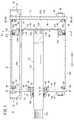
本発明に係る流体圧シリンダについて好適な実施の形態を挙げ、添付の図面を参照しながら以下詳細に説明する。図1において、参照符号10は、本発明の第1の実施の形態に係る流体圧シリンダを示す。 A preferred embodiment of a fluid pressure cylinder according to the present invention will be described below and described in detail with reference to the accompanying drawings. In FIG. 1,
この流体圧シリンダ10は、図1に示されるように、円筒状のシリンダチューブ12と、該シリンダチューブ12の一端部に装着されるヘッドカバー(カバー部材)14と、前記シリンダチューブ12の他端部に装着されるロッドカバー(カバー部材)16と、前記シリンダチューブ12の内部に変位自在に設けられるピストンユニット(ピストン)18と、前記ピストンユニット18に連結されるピストンロッド20とを含む。 As shown in FIG. 1, the
シリンダチューブ12は、例えば、金属製材料から形成され軸方向(矢印A、B方向)に沿って一定断面積で延在した筒体からなり、その内部にはピストンユニット18の収容されるシリンダ室22a、22bが形成される。また、シリンダチューブ12の両端部には、環状溝を介してリング状のシール部材(図示せず)がそれぞれ装着される。 The
ヘッドカバー14は、図1〜図3A、図4Aに示されるように、例えば、金属製材料から断面略矩形状に形成されたプレート体であり、シリンダチューブ12の一端部を閉塞するように設けられる。この際、シリンダチューブ12の端部に設けられたシール部材(図示せず)がヘッドカバー14へと当接することで、前記シリンダチューブ12と前記ヘッドカバー14との間を通じたシリンダ室22aからの圧力流体の漏れが防止される。 As shown in FIGS. 1 to 3A and 4A, the
また、図4Aに示されるように、ヘッドカバー14の四隅近傍には、後述する連結ロッド88が挿通される4つの第1孔部26がそれぞれ形成されると共に、前記第1孔部26に対してヘッドカバー14の中央側となる位置には第1連通孔28が形成される。第1孔部26及び第1連通孔28は、図1及び図2に示されるヘッドカバー14の厚さ方向(矢印A、B方向)にそれぞれ貫通している。 As shown in FIG. 4A, four
このヘッドカバー14の外壁面14aには、圧力流体を供給・排出するための第1ポート部材30が設けられ、図示しない配管を介して圧力流体供給源と接続される。この第1ポート部材30は、例えば、金属製材料から形成されたブロック体からなり溶接等によって固定される。また、第1ポート部材30の内部には、断面L字状に形成されたポート通路32が形成され、その開口部がシリンダチューブ12の軸線と直交方向に開口した状態でヘッドカバー14の外壁面14aに対して固定される。 A
そして、第1ポート部材30は、ポート通路32がヘッドカバー14の第1連通孔28と連通することで、前記第1ポート部材30とシリンダチューブ12の内部とが連通する。 The
なお、第1ポート部材30を設ける代わりに、例えば、第1連通孔28に対して配管接続用の継手を直接接続するようにしてもよい。 Instead of providing the
一方、シリンダチューブ12側(矢印A方向)となるヘッドカバー14の内壁面14bには、図1、図2及び図4Aに示されるように、前記シリンダチューブ12の内周径に対して小径となる円周ピッチ上に複数(例えば、3個)の第1ピン孔34が形成され、前記第1ピン孔34にはそれぞれ第1インローピン36が挿入される。第1ピン孔34は、ヘッドカバー14の中心に対する所定直径の円周上に形成され、周方向に沿って互いに等間隔離間するように形成される。
On the other hand, the
この第1インローピン36は、第1ピン孔34と同数となるように複数設けられ、断面円形状で形成された鍔部38と、該鍔部38に対して小径で第1ピン孔34へ挿入される軸部40とからなる。そして、第1インローピン36は、軸部40が第1ピン孔34へと圧入されることで、それぞれヘッドカバー14の内壁面14bに対して固定され、鍔部38がヘッドカバー14の内壁面14bに対して突出した状態となる。 A plurality of the first spigot pins 36 are provided so as to have the same number as the first pin holes 34, and a
この第1インローピン36の鍔部38は、その外周面がヘッドカバー14に対してシリンダチューブ12を組み付ける際、図4Aに示されるように該シリンダチューブ12の内周面に対してそれぞれ内接することで、ヘッドカバー14に対するシリンダチューブ12の位置決めがなされる。すなわち、複数の第1インローピン36は、ヘッドカバー14に対してシリンダチューブ12の一端部を位置決めするための位置決め手段として機能する。 When the
換言すれば、第1インローピン36は、その外周面がシリンダチューブ12の内周面に内接するような所定直径の円周上に配置されている。 In other words, the
ヘッドカバー14の内壁面14bにはリング状の第1ダンパ42が設けられる。この第1ダンパ42は、例えば、ゴム等の弾性材料から所定厚さで形成され、その内周面が第1連通孔28よりも半径外方向となるように配置される(図2及び図4A参照)。 A ring-shaped
また、第1ダンパ42には、その外周面から半径内方向に向かって断面略円形状に窪んだ複数の切欠部44を有し、前記切欠部44には第1インローピン36が挿入される。すなわち、切欠部44は、第1インローピン36と同数且つ同一円周上に同ピッチで設けられる。そして、第1ダンパ42は、図2に示されるように、第1インローピン36の鍔部38によってヘッドカバー14の内壁面14bとの間に挟持されることで、該内壁面14bに対して所定高さだけ突出した状態で保持される。 The
すなわち、第1インローピン36は、シリンダチューブ12の一端部をヘッドカバー14に対して所定位置へ位置決めする位置決め手段(インロー手段)であると同時に、第1ダンパ42を前記ヘッドカバー14へ固定するための固定手段としても機能する。 That is, the
そして、ピストンユニット18がヘッドカバー14側(矢印B方向)へと変位した際、その端部が第1ダンパ42へと当接することで、前記ピストンユニット18が前記ヘッドカバー14に対して直接接触することが回避され、接触に伴う衝撃及び衝撃音の発生が好適に防止される。 When the
また、ヘッドカバー14には、第1連通孔28に対してさらに中央側となる位置に、後述するガイドロッド124の支持される第1ロッド孔46が形成される。なお、第1ロッド孔46は、ヘッドカバー14の内壁面14b側(矢印A方向)に開口し外壁面14aまでは貫通していない。 Further, the
ロッドカバー16は、図1、図3B及び図4Bに示され、ヘッドカバー14と同様に、例えば、金属製材料から断面略矩形状に形成されたプレート体であり、シリンダチューブ12の他端部を閉塞するように設けられる。この際、シリンダチューブ12の端部に設けられたシール部材(図示せず)がロッドカバー16へと当接することで、前記シリンダチューブ12と前記ロッドカバー16との間を通じたシリンダ室22bからの圧力流体の漏れが防止される。 The
このロッドカバー16の中央には軸方向(矢印A、B方向)に沿って貫通したロッド孔48が形成されると共に、その四隅には後述する連結ロッド88が挿通される4つの第2孔部50が形成される。また、ロッドカバー16には、第2孔部50に対して中心側となる位置に第2連通孔52が形成される。このロッド孔48、第2孔部50及び第2連通孔52は、それぞれロッドカバー16の厚さ方向(矢印A、B方向)に貫通して形成される。 A
このロッド孔48には、ピストンロッド20を変位自在に支持するホルダ54が設けられる。このホルダ54は、例えば、金属製材料から絞り加工等によって形成され、円筒状のホルダ本体56と、該ホルダ本体56の一端部に形成され半径外方向に拡径したフランジ部58とを有し、前記ホルダ本体56の一部が前記ロッドカバー16から外側に突出するように設けられる(図1参照)。 The
そして、ロッドカバー16のロッド孔48にホルダ本体56が挿通され、フランジ部58がシリンダチューブ12側(矢印B方向)に配置された状態で、前記フランジ部58をロッドカバー16の内壁面16bに当接させ複数(例えば、4本)の第1リベット60を前記フランジ部58の第1貫通孔62を介して前記ロッドカバー16の第1リベット孔64へ挿入して係合させる。これにより、ロッドカバー16のロッド孔48に対してホルダ54が固定される。この際、ホルダ54は、ロッド孔48と同軸上となるように固定される。 The
この第1リベット60は、例えば、円形状の鍔部66と、該鍔部66に対して縮径した軸状のピン部68とを有した自己穿孔式リベットである。そして、第1リベット60を、フランジ部58側から第1貫通孔62へと挿入し、その鍔部66を前記フランジ部58に係合させた状態で、前記ピン部68を前記ロッドカバー16の第1リベット孔64へと打ち込むことで、該ピン部68が第1貫通孔62に対して係合されフランジ部58がロッドカバー16に対して固定される。 The
なお、第1リベット60は、自己穿孔式リベットに限定されるものではなく、例えば、ピン部68をロッドカバー16の外壁面16a側まで突出させた後に押し潰して変形させ固定する一般的なリベットであってもよい。 The
このホルダ54の内部には、軸方向(矢印A、B方向)に沿って並ぶようにブッシュ70及びロッドパッキン72が設けられ、後述するピストンロッド20が内部に挿通されることで、前記ブッシュ70によって軸方向に沿ってガイドされると同時に、ロッドパッキン72が摺接することで前記ホルダ54と前記ロッドパッキン72との間を通じた圧力流体の漏れが防止される。 Inside the
このロッドカバー16の外壁面16aには、図1及び図3Bに示されるように、圧力流体を供給・排出するための第2ポート部材74が設けられ、図示しない配管を介して圧力流体供給源と接続される。この第2ポート部材74は、例えば、金属製材料から形成されたブロック体からなり溶接等によって固定される。また、第2ポート部材74の内部には、断面L字状に形成されたポート通路76が形成され、その開口部がシリンダチューブ12の軸線と直交方向に開口した状態でロッドカバー16の外壁面16aに対して固定される。 As shown in FIGS. 1 and 3B, the
そして、第2ポート部材74は、ポート通路76がロッドカバー16の第2連通孔52と連通することで、前記第2ポート部材74とシリンダチューブ12の内部とが連通する。 In the
なお、第2ポート部材74を設ける代わりに、例えば、第2連通孔52に対して配管接続用の継手を直接接続するようにしてもよい。 Instead of providing the
一方、シリンダチューブ12側(矢印B方向)となるロッドカバー16の内壁面16bには、図1及び図4Bに示されるように、前記シリンダチューブ12の内周径に対して小径となる円周ピッチ上に複数(例えば、3個)の第2ピン孔78が形成され、前記第2ピン孔78にはそれぞれ第2インローピン80が挿入される。すなわち、第2インローピン80は、第2ピン孔78と同数となるように複数設けられる。 On the other hand, on the
第2ピン孔78は、ロッドカバー16の中心に対する所定直径の円周上に形成され、周方向に沿って互いに等間隔離間するように形成される。なお、第2インローピン80は、第1インローピン36と同一形状で形成されるため、その詳細な説明については省略する。
The second pin holes 78 are formed ona circumference having a predetermined diameterwith respect to the center of the
そして、第2インローピン80の軸部40が第2ピン孔78へと圧入されることで、前記第2インローピン80がそれぞれロッドカバー16の内壁面16bに対して固定され、鍔部38がロッドカバー16の内壁面16bに対して突出した状態となる。 Then, when the
また、第2インローピン80の鍔部38は、その外周面がロッドカバー16に対してシリンダチューブ12を組み付ける際、図4Bに示されるように、該シリンダチューブ12の内周面に対してそれぞれ内接することで、ロッドカバー16に対するシリンダチューブ12の位置決めがなされる。すなわち、複数の第2インローピン80は、ロッドカバー16に対してシリンダチューブ12の他端部を位置決めするための位置決め手段として機能する。 Further, when the
換言すれば、第2インローピン80は、その外周面がシリンダチューブ12の内周面に内接するような所定直径の円周上に配置されている。 In other words, the
ロッドカバー16の内壁面16bにはリング状の第2ダンパ82が設けられる。この第2ダンパ82は、例えば、ゴム等の弾性材料から所定厚さで形成され、その内周面が第2連通孔52よりも半径外方向となるように配置される。 A ring-shaped
また、第2ダンパ82には、その外周面から半径内方向に向かって断面略円形状に窪んだ複数の切欠部84を有し、前記切欠部84には第2インローピン80が挿入される。そして、第2ダンパ82は、第2インローピン80の鍔部38によってロッドカバー16の内壁面16bとの間に挟持されることで、該内壁面16bに対して所定高さだけ突出した状態で保持される。 The
すなわち、切欠部84は、第2インローピン80と同数且つ同一円周上に同ピッチで設けられる。That is, the
このように、第2インローピン80は、シリンダチューブ12の他端部をロッドカバー16に対して所定位置へ位置決めする位置決め手段(インロー手段)であると同時に、第2ダンパ82を前記ロッドカバー16へ固定するための固定手段としても機能する。 Thus, the
そして、ピストンユニット18がロッドカバー16側(矢印A方向)へと変位した際、その端部が第2ダンパ82へと当接することで、前記ピストンユニット18が前記ロッドカバー16に対して直接接触することが回避され、接触に伴う衝撃及び衝撃音の発生が好適に防止される。 When the
また、第2連通孔52に対してさらにロッドカバー16の中心側となる位置に、後述するガイドロッド124の支持される第2ロッド孔86が形成される。なお、第2ロッド孔86は、図1に示されるように、ロッドカバー16の内壁面16b側(矢印B方向)に開口し外壁面16aまでは貫通していない。 In addition, a
そして、シリンダチューブ12の一端部にヘッドカバー14の内壁面14bを当接させ、他端部にロッドカバー16の内壁面16bを当接させた状態で、4つの第1及び第2孔部26、50に連結ロッド88をそれぞれ挿通させ、その両端部に締結ナット90(図1、図3A、図3B参照)を螺合させ前記ヘッドカバー14及びロッドカバー16の外壁面14a、16aに当接するまで締め付ける。これにより、シリンダチューブ12がヘッドカバー14とロッドカバー16との間に挟持された状態で固定される。 Then, with the
また、連結ロッド88には、図5に示されるように、ピストンユニット18の位置を検出するための検出センサ92を保持するセンサ保持体94が設けられる。このセンサ保持体94は、連結ロッド88の延在方向に対して略直交するように設けられ、該連結ロッド88に沿って移動可能に設けられると共に、該連結ロッド88に保持された部位から延在して検出センサ92の装着される装着部96を有している。装着部96には、例えば、断面円形状で連結ロッド88と略平行な溝部が形成され、該溝部に検出センサ92が収納され保持される。 Further, as shown in FIG. 5, the connecting
この検出センサ92は、後述するリング体100のマグネット122が有している磁気を検出可能な磁気センサである。なお、この検出センサ92を含むセンサ保持体94は必要に応じた数量だけ選択的に設けられる。 The
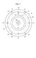
ピストンユニット18は、図1、図2、図6及び図7に示されるように、ピストンロッド20の一端部に連結される円盤状のプレート体98と、該プレート体98の外縁部に連結されるリング体100とを含む。 As shown in FIGS. 1, 2, 6, and 7, the
プレート体98は、例えば、弾性を有した金属製の板材から略一定厚さで形成され、その中央部には厚さ方向に貫通した複数(例えば、4個)の第2貫通孔102が設けられる。そして、第2貫通孔102には第2リベット(ピン部材)104が挿入され、その先端がピストンロッド20の一端部に形成された第2リベット孔106へ挿入され係合されることで、前記ピストンロッド20の一端部にプレート体98が略直交するように連結される。 The
この第2リベット104は、第1リベット60と同様に、例えば、自己穿孔式リベットであり、その鍔部66がプレート体98のヘッドカバー14側(矢印B方向)となるように挿入した後、ピン部68を前記ピストンロッド20の内部へと打ち込むことで第2リベット孔106に対して係合させ、プレート体98がピストンロッド20に対して係止される。 The
また、プレート体98の外縁部には、厚さ方向に貫通した複数(例えば、4個)の第3貫通孔108が設けられ、前記第3貫通孔108は、前記プレート体98の周方向に沿って互いに等間隔離間して形成されると共に、前記プレート体98の中心に対して同一直径上となるように形成される。 A plurality of (for example, four) third through
さらに、プレート体98には、第3貫通孔108より内周側となる位置に、厚さ方向に貫通したロッド挿通孔110が形成され、後述するガイドロッド124が挿通される。 Further, a
さらにまた、プレート体98には、ピストンロッド20に固定される中心部と外縁部との間となる位置に、例えば、断面湾曲状に突出したリブ112を有し、前記リブ112は、周方向に沿った環状に形成されると共に、ピストンロッド20側とは反対側(矢印B方向)に向かって突出するように形成される。また、リブ112は、ピストンロッド20側(矢印A方向)に向かって突出するように形成してもよい。なお、リブ112は、ロッド挿通孔110より内周側となる位置に形成される。 Furthermore, the
このリブ112を設けることで弾性を有したプレート体98の撓み具合を所定量に設定している。換言すれば、このリブ112の位置や形状を適宜変更することで、プレート体98の撓み量を自在に調整することが可能となる。また、上述したリブ112を設けなくてもよい。 By providing the
なお、このプレート体98は、ピストンロッド20の端部に第2リベット104で連結される場合に限定されるものではなく、例えば、前記ピストンロッド20の端部にピン部材を圧入して端部を塑性変形させることで連結するようにしてもよい。 The
リング体100は、例えば、金属製材料から断面円形状に形成され、ヘッドカバー14側(矢印B方向)となる端面にプレート体98の外縁部が当接し、複数の第3リベット114によって固定されている。この第3リベット114は、第1及び第2リベット60、104と同様に、例えば、自己穿孔式リベットであり、その鍔部66をプレート体98のヘッドカバー14側(矢印B方向)となるように挿入した後、ピン部68を前記リング体100の第3リベット孔115へと打ち込むことで内部に係合され係止される。 The
また、リング体100には、図2に示されるように、外周面に形成された環状溝を介してピストンパッキン116及びウェアリング118が設けられ、前記ピストンパッキン116が前記シリンダチューブ12の内周面に摺接することで、前記リング体100と前記シリンダチューブ12との間を通じた圧力流体の漏出を防止し、前記ウェアリング118が前記シリンダチューブ12の内周面に摺接することで、前記リング体100が前記シリンダチューブ12に沿って軸方向(矢印A、B方向)に案内される。 Further, as shown in FIG. 2, the
さらに、図1及び図2に示されるように、ヘッドカバー14に臨むリング体100の側面には、軸方向に沿って開口した複数(例えば、4個)の孔部120が形成され、その内部には円柱状のマグネット122がそれぞれ圧入される。このマグネット122の配置は、ピストンユニット18をシリンダチューブ12の内部に設けた際、図5に示されるように、4本の連結ロッド88に臨む位置となるように設けられ、前記連結ロッド88に設けられたセンサ保持体94の検出センサ92によって前記マグネット122の磁気が検出される。 Further, as shown in FIGS. 1 and 2, a plurality of (for example, four)
ガイドロッド124は、図1、図2、図4A〜図5に示されるように、断面円形状で軸状に形成され、その一端部がヘッドカバー14の第1ロッド孔46へ挿入され、他端部がロッドカバー16の第2ロッド孔86へと挿入されると共に、プレート体98のロッド挿通孔110へ挿通される。これにより、ガイドロッド124は、シリンダチューブ12の内部において、ヘッドカバー14及びロッドカバー16に固定されピストンユニット18の軸方向(変位方向)と平行に設けられると共に、前記ピストンユニット18が軸方向に変位する際に回転してしまうことが防止される。換言すれば、ガイドロッド124はピストンユニット18の回り止めとして機能する。 As shown in FIGS. 1, 2, and 4 </ b> A to 5, the
また、ロッド挿通孔110にはОリングが設けられ、該ロッド挿通孔110とガイドロッド124との間を通じた圧力流体の漏れを防止している。 The
ピストンロッド20は、図1に示されるように、軸方向(矢印A、B方向)に沿って所定長さを有した軸体からなり、略一定径で形成された本体部126と、該本体部126の他端部に形成された小径な先端部128とを有し、前記先端部128がホルダ54を介してロッドカバー16の外側に露出するように設けられる。この本体部126の一端部は、ピストンロッド20の軸方向と直交した略平面状に形成され、プレート体98が連結されている。 As shown in FIG. 1, the
本発明の第1の実施の形態に係る流体圧シリンダ10は、基本的には以上のように構成されるものであり、次にその動作並びに作用効果について説明する。なお、ピストンユニット18がヘッドカバー14側(矢印B方向)に変位した状態を初期位置として説明する。 The
先ず、図示しない圧力流体供給源から圧力流体を第1ポート部材30へと導入する。この場合、第2ポート部材74は、図示しない切換弁による切換作用下に大気開放状態としておく。これにより、圧力流体が、第1ポート部材30からポート通路32及び第1連通孔28へと供給され、前記第1連通孔28からシリンダ室22aへと導入された圧力流体によってピストンユニット18がロッドカバー16側(矢印A方向)へと押圧される。そして、ピストンユニット18と共にピストンロッド20が変位し、リング体100の端面が第2ダンパ82へと当接することで変位終端位置となる。 First, pressure fluid is introduced into the
一方、ピストンユニット18を前記とは反対方向(矢印B方向)に変位させる場合には、第2ポート部材74へ圧力流体を供給すると共に、第1ポート部材30を切換弁(図示せず)の切換作用下に大気開放状態とする。そして、圧力流体が、第2ポート部材74からポート通路76及び第2連通孔52を通じてシリンダ室22bへと供給され、該シリンダ室22bへと導入された圧力流体によってピストンユニット18がヘッドカバー14側(矢印B方向)へと押圧される。 On the other hand, when the
そして、ピストンユニット18の変位作用下にピストンロッド20が共に変位し、前記ピストンユニット18のリング体100がヘッドカバー14の第1ダンパ42へと当接することで初期位置へと復帰する。 Then, the
また、上述したようにピストンユニット18がシリンダチューブ12に沿って軸方向(矢印A、B方向)に変位する際、ピストンユニット18の内部に挿通されたガイドロッド124に沿って変位することで回転変位してしまうことがなく、該ピストンユニット18に設けられたマグネット122が検出センサ92に臨む位置となり、ピストンユニット18の変位が検出センサ92によって確実に検出される。 Further, as described above, when the
以上のように、第1の実施の形態では、流体圧シリンダ10を構成するピストンユニット18において、板材からなるプレート体98をピストンロッド20の一端部へ第2リベット104で連結する構成としているため、ピストンをピストンロッドに対してねじ等で連結していた従来の流体圧シリンダと比較し、前記ねじより軸長さの短いリベット(第2リベット104)で略同等の締結力を得ることが可能となる。その結果、従来の流体圧シリンダと比較し、ピストンユニット18の軸方向(矢印A、B方向)に沿った寸法を短縮することができ、それに伴って、流体圧シリンダ10の軸方向に沿った寸法を小型化することが可能となる。 As described above, in the first embodiment, in the
また、第2リベット104の鍔部66は、一般的なねじ等の頭部と比較して薄いため、ピストンユニット18においてヘッドカバー14側(矢印B方向)への突出量を低減することが可能となり、前記ピストンユニット18の軸方向に沿った寸法(全長)の低減に寄与することができる。 Further, since the
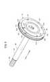
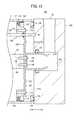
一方、ピストンユニット18は上述した構成に限定されるものではなく、例えば、図8Aに示されるピストンユニット150のように、テーパ部152を有したピストンロッド154の一端部に対応させ、プレート体156の中央部にヘッドカバー14側(矢印B方向)に向かって膨出した膨出部(位置決め部)158を備え、該膨出部158を介して複数の第2リベット104によって前記ピストンロッド154と連結するようにしてもよい。 On the other hand, the
この膨出部158は、例えば、断面略U字状に形成され、プレート体156のベース部160に対して傾斜した傾斜部162と、該傾斜部162の先端に形成される平坦部164とからなり、前記ベース部160と前記平坦部164とが略平行に形成される。なお、傾斜部162は環状に形成される。 For example, the bulging
そして、膨出部158は、ピストンロッド154の一端部を覆うように装着され、平坦部164を平面状の一端部に当接させ、傾斜部162をテーパ部152へと当接させた状態で、前記傾斜部162に直交するように複数の第2リベット104がピストンロッド154側へと打ち込まれることでプレート体156が前記ピストンロッド154へと固定される。 The bulging
すなわち、第2リベット104は、ピストンロッド154の軸線に対して所定角度傾斜するように打ち込まれる。 That is, the
このように、プレート体156の中央部に膨出部158を設け、ピストンロッド154の一端部へと係合させ連結することで、前記ピストンロッド154に対してプレート体156を同軸状に容易且つ確実に位置決めできると共に、前記ピストンロッド154の軸線に対して傾斜した角度から第2リベット104を打ち込むことで、ピストンユニット150の変位方向と前記第2リベット104の締結方向とが一直線状ではないため、前記ピストンユニット150の変位動作に伴って締結が緩んでしまうことが防止される。 In this manner, the bulging
また、図8Bに示されるピストンユニット170のように、プレート体172の中央部にピストンロッド20の挿入可能な挿入孔174を有し、前記挿入孔174から軸方向(矢印A方向)に延在した筒部176を備え、前記筒部176及び挿入孔174にピストンロッド20の一端部が挿入された状態で、前記筒部176の外周側から前記ピストンロッド20に向かって複数の第2リベット104を打ち込んで互いに連結するようにしてもよい。 Further, like the
この場合にも、上述したピストンユニット150と同様に、プレート体172の挿入孔174へピストンロッド20を挿入することで、前記ピストンロッド20に対してプレート体172の同軸状に容易且つ確実に位置決めできると共に、前記ピストンロッド20の軸線に対して略直交方向から第2リベット104を打ち込むことで、ピストンユニット170の変位方向(矢印A、B方向)と前記第2リベット104の締結方向とが直交して同一方向ではないため、前記ピストンユニット170の変位動作に伴った締結の緩みをより確実に防止することができる。 Also in this case, similarly to the
図9に示されるピストンユニット180は、クッション機構を有した流体圧シリンダ182に設けられ、ヘッドカバー184に臨むプレート体98の側面に円筒状のクッション部材186が連結される。 The
このクッション部材186は、例えば、有底円筒状に形成され、その開口部には半径外方向に拡径した取付フランジ188が形成される。そして、クッション部材186は、その底部190をヘッドカバー184側(矢印B方向)とし、取付フランジ188をプレート体98に当接させた状態で、前記取付フランジ188と前記プレート体98とが複数の第4リベット192によって連結される。 The
なお、クッション部材186は、その取付フランジ188が第2リベット104の外側となる位置に固定される。 The
そして、圧力流体の供給作用下にピストンユニット180がヘッドカバー184側(矢印B方向)へと変位し、そのクッション部材186が前記ヘッドカバー184のクッション孔194へと徐々に挿入され、且つ、その外周面に設けられたシールリング196に摺接しながら変位していくことで、圧力流体の流量が絞られてシリンダ室22a内で圧縮される。その結果、ピストンユニット180が変位する際の変位抵抗となり、該ピストンユニット180の変位速度が変位終端位置に近づくにつれて徐々に低下する。 Then, the
このように、ピストンユニット180を構成するプレート体98にクッション部材186を第4リベット192によって連結することにより、容易に前記クッション部材186を追加することができるため、クッション機構を有した流体圧シリンダ182に対応させることが可能となる。また、クッション機構の特性に応じたクッション部材186を適宜選択して装着することが可能となる。 As described above, the
また、クッション部材186は、上述したピストンユニット180のように有底円筒状に形成され、その底部190がピストンロッド20とは反対側となる端部に配置された構成に限定されるものではなく、例えば、図10に示されるピストンユニット200を有した流体圧シリンダ202のように、ピストンロッド20とは反対側の端部が開口した有底円筒状のクッション部材204を用いるようにしてもよい。 Further, the
このクッション部材204は、断面U字状に形成され、その底部206がピストンロッド20と同軸状となるようにプレート体98の側面に当接し、第2リベット104によってプレート体98と共にピストンロッド20の一端部に連結される。換言すれば、クッション部材204は、プレート体98と共にピストンロッド20に対して共締めされる。 The
この第2リベット104は、クッション部材204の開口した端部から内部へと挿入され、その鍔部66がヘッドカバー184側となるように配置された状態で、前記端部側から図示しない打ち込み装置によって頭部を打つことでクッション部材204、プレート体98及びピストンロッド20を一体的に連結している。 The
このように、ピストンユニット200を構成するプレート体98にクッション部材204を第2リベット104によって連結することにより、容易に前記クッション部材204を追加することができるため、クッション機構を有した流体圧シリンダ202に対応させることが可能となる。 In this way, the
また、クッション部材204が、プレート体98とピストンロッド20とを連結するための第2リベット104を利用して固定できるため、リベットの数量が増加してしまうことがなく部品点数の増加を抑制できると共に、組付工数の削減を図ることが可能となる。 Moreover, since the
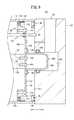
次に、第2の実施の形態に係る流体圧シリンダ220を図11に示す。なお、上述した第1の実施の形態に係る流体圧シリンダ10と同一の構成要素には同一の参照符号を付して、その詳細な説明を省略する。 Next, a
この流体圧シリンダ220は、シリンダチューブ12の両端部に設けられた第1及び第2エンドカバー222、224からそれぞれピストンロッド226の両端部が突出した両ロッド式である点で、第1の実施の形態に係る片ロッド式の流体圧シリンダ10と相違している。 The
この流体圧シリンダは、図11に示されるように、シリンダチューブ12の両端部にそれぞれ第1及び第2エンドカバー222、224を備え、前記第1及び第2エンドカバー222、224は、前記シリンダチューブ12を挟んで略対称形状となるように形成される。この第1及び第2エンドカバー222、224の略中央部には、それぞれロッド孔48を介してホルダ228a、228bが設けられ第1リベット60によってそれぞれ固定されている。 As shown in FIG. 11, the fluid pressure cylinder includes first and second end covers 222 and 224 at both ends of the
また、シリンダチューブ12の内部に設けられたピストンユニット230は、略中央部に挿入孔232を有したプレート体234と、該プレート体234の外縁部に連結されたリング体100とを有し、前記挿入孔232にピストンロッド226の略中央部が挿通され、前記挿入孔232から延在したプレート体234の筒部236と前記ピストンロッド226とが第2リベット238によって径方向に固定される。 The
この第2リベット238は、例えば、プレート体234の筒部236に形成された第2貫通孔240aを通じてピストンロッド226側へと挿入され、該ピストンロッド226の軸線と略直交して貫通した第2リベット孔242へと打ち込まれ、突出した先端によって反対側となる筒部236の第2貫通孔240bへと係合させる。すなわち、第2リベット238は、ピストンロッド226の軸線と略直交方向に打ち込まれる。 The
なお、プレート体234とピストンロッド226との連結は、上述したように単一の第2リベット238によって行われる場合に限定されるものではなく、例えば、筒部236の外周側からピストンロッド226側に向かって複数の第2リベット238を打ち込むことで互いに連結するようにしてもよい。 The connection between the
そして、ピストンロッド226の一端部が、第1エンドカバー222に固定されたホルダ228aを通じて外部へと突出し変位自在に支持され、前記ピストンロッド226の他端部が、第2エンドカバー224に固定されたホルダ228bを通じて外部へと突出し変位自在に支持される。 One end of the
このような流体圧シリンダ220では、例えば、第1エンドカバー222に設けられた第1ポート部材30からシリンダ室22aへと圧力流体を供給することで、ピストンユニット230が第2エンドカバー224側(矢印A方向)に向かって押圧され変位し、ピストンロッド226の一端部側が徐々にシリンダチューブ12内へと収納されていくと共に他端部側が徐々に第2エンドカバー224から外部へと突出していく。 In such a
一方、ピストンユニット230を上記とは反対方向(矢印B方向)に変位させる場合には、第2ポート部材74を通じて圧力流体をシリンダ室22bへと供給することで、ピストンユニット230が第1エンドカバー222側(矢印B方向)に向かって押圧され変位し、ピストンロッド226の一端部側が徐々に前記第1エンドカバー222から外部へと突出していくと共に、他端部が徐々にシリンダチューブ12内へと収納されていく。 On the other hand, when the
以上のように、第2の実施の形態では、単一のピストンロッド226の略中央部にピストンユニット230を設け、そのプレート体234の外周側から第2リベット238を前記ピストンロッド226側へと打ち込むことで、両ロッド式の流体圧シリンダ220を構成するピストンユニット230を容易に構成することができる。 As described above, in the second embodiment, the
また、ピストンロッド226に対して加工を行うことなくピストンユニット230を固定できるため、単一のピストンロッド226を共用してピストンユニット230の位置を変更することで容易に仕様変更に対応することが可能となる。 In addition, since the
なお、本発明に係る流体圧シリンダは、上述の実施の形態に限らず、本発明の要旨を逸脱することなく、種々の構成を採り得ることはもちろんである。 In addition, the fluid pressure cylinder according to the present invention is not limited to the above-described embodiment, and it is needless to say that various configurations can be adopted without departing from the gist of the present invention.
10、182、202、220…流体圧シリンダ
12…シリンダチューブ 14、184…ヘッドカバー
16…ロッドカバー
18、150、170、180、200、230…ピストンユニット
20、154、226…ピストンロッド
22a、22b…シリンダ室 38、66…鍔部
54、228a、228b…ホルダ 60…第1リベット
98、156、172、234…プレート体
100…リング体 104、238…第2リベット
158…膨出部 174、232…挿入孔
176、236…筒部 186、204…クッション部材
194…クッション孔 222…第1エンドカバー
224…第2エンドカバー10, 182, 202, 220 ...
Claims (4)
Translated fromJapanese前記ピストンは、前記ピストンロッドの端部に連結されるプレート体と、前記プレート体の外縁部に設けられ前記シリンダチューブの内周面に摺接する環状のリング体とからなり、
前記プレート体の中央部には、テーパ部を有する前記ピストンロッドの端部が挿入されて同軸状に位置決めされる膨出部が設けられ、前記膨出部を貫通するピン部材によって前記プレート体と前記ピストンロッドとが連結されることを特徴とする流体圧シリンダ。A cylinder tube having a cylinder chamber therein; a cover member attached to an end portion of the cylinder tube; a piston provided to be displaceable along the cylinder chamber; and a piston rod coupled to the piston. In the fluid pressure cylinder,
The piston is composed of a plate body connected to an end of the piston rod, and an annular ring body provided at an outer edge of the plate body and in sliding contact with the inner peripheral surface of the cylinder tube,
In the center of the plate body, an end portion of the piston rod having a taper portion is inserted, and a bulging portion that is positioned coaxially is provided, and the plate body is connected to the plate body by a pin member that penetrates the bulging portion. A fluid pressure cylinderconnected to the piston rod .
前記ピン部材は、前記ピストンロッドの軸方向に対して所定角度傾斜して該ピストンロッドに対して打ち込まれる複数のリベットであることを特徴とする流体圧シリンダ。The fluid pressure cylinder according to claim1 , wherein
The fluid pressure cylinder according to claim 1, wherein the pin member is aplurality of rivets that are driven into the piston rod while being inclined at a predetermined angle with respect to an axial direction of the piston rod.
前記ピストンは、前記ピストンロッドの端部に連結されるプレート体と、前記プレート体の外縁部に設けられ前記シリンダチューブの内周面に摺接する環状のリング体とからなり、The piston is composed of a plate body connected to an end of the piston rod, and an annular ring body provided at an outer edge of the plate body and in sliding contact with the inner peripheral surface of the cylinder tube,
前記プレート体の中央部には、前記ピストンロッドから離間する方向に突出するクッション部材が設けられ、前記クッション部材と前記プレート体とが共通のピン部材によって前記ピストンロッドに連結され、前記クッション部材が前記カバー部材の収納孔へ収納されることで前記ピストンの変位速度が減速されることを特徴とする流体圧シリンダ。A cushion member protruding in a direction away from the piston rod is provided at the center of the plate body, and the cushion member and the plate body are connected to the piston rod by a common pin member, and the cushion member is The fluid pressure cylinder, wherein the displacement speed of the piston is reduced by being housed in the housing hole of the cover member.
前記ピン部材は、前記ピストンロッドの軸方向に沿って該ピストンロッドに対して打ち込まれるリベットであることを特徴とする流体圧シリンダ。The fluid pressure cylinder according to claim 1, wherein the pin member is a rivet that is driven into the piston rod along an axial direction of the piston rod.
Priority Applications (10)
| Application Number | Priority Date | Filing Date | Title |
|---|---|---|---|
| JP2015118205AJP6403073B2 (en) | 2015-06-11 | 2015-06-11 | Fluid pressure cylinder |
| PCT/JP2016/002638WO2016199376A1 (en) | 2015-06-11 | 2016-06-01 | Fluid pressure cylinder |
| RU2018100829ARU2682216C1 (en) | 2015-06-11 | 2016-06-01 | Hydro(pneumatic)cylinder |
| BR112017026675-0ABR112017026675A2 (en) | 2015-06-11 | 2016-06-01 | fluid pressure cylinder |
| EP16730022.7AEP3308036B1 (en) | 2015-06-11 | 2016-06-01 | Fluid pressure cylinder |
| MX2017016130AMX2017016130A (en) | 2015-06-11 | 2016-06-01 | Fluid pressure cylinder. |
| CN201680033045.6ACN107690528B (en) | 2015-06-11 | 2016-06-01 | Fluid pressure cylinder |
| US15/580,124US10677270B2 (en) | 2015-06-11 | 2016-06-01 | Fluid pressure cylinder |
| KR1020187000916AKR102079672B1 (en) | 2015-06-11 | 2016-06-01 | Hydraulic cylinder |
| TW105118151ATWI607157B (en) | 2015-06-11 | 2016-06-08 | Fluid pressure cylinder |
Applications Claiming Priority (1)
| Application Number | Priority Date | Filing Date | Title |
|---|---|---|---|
| JP2015118205AJP6403073B2 (en) | 2015-06-11 | 2015-06-11 | Fluid pressure cylinder |
Publications (3)
| Publication Number | Publication Date |
|---|---|
| JP2017003025A JP2017003025A (en) | 2017-01-05 |
| JP2017003025A5 JP2017003025A5 (en) | 2017-03-30 |
| JP6403073B2true JP6403073B2 (en) | 2018-10-10 |
Family
ID=56134523
Family Applications (1)
| Application Number | Title | Priority Date | Filing Date |
|---|---|---|---|
| JP2015118205AActiveJP6403073B2 (en) | 2015-06-11 | 2015-06-11 | Fluid pressure cylinder |
Country Status (10)
| Country | Link |
|---|---|
| US (1) | US10677270B2 (en) |
| EP (1) | EP3308036B1 (en) |
| JP (1) | JP6403073B2 (en) |
| KR (1) | KR102079672B1 (en) |
| CN (1) | CN107690528B (en) |
| BR (1) | BR112017026675A2 (en) |
| MX (1) | MX2017016130A (en) |
| RU (1) | RU2682216C1 (en) |
| TW (1) | TWI607157B (en) |
| WO (1) | WO2016199376A1 (en) |
Families Citing this family (2)
| Publication number | Priority date | Publication date | Assignee | Title |
|---|---|---|---|---|
| JP6673555B2 (en)* | 2017-05-08 | 2020-03-25 | Smc株式会社 | Fluid pressure cylinder |
| JP7323103B2 (en)* | 2020-07-22 | 2023-08-08 | Smc株式会社 | hydraulic cylinder |
Family Cites Families (78)
| Publication number | Priority date | Publication date | Assignee | Title |
|---|---|---|---|---|
| US2616687A (en) | 1947-03-18 | 1952-11-04 | Chrysler Corp | Suspension |
| US3175474A (en) | 1960-05-17 | 1965-03-30 | Eickmann Karl | Closure device for hydraulic cylinder or the like |
| US3136225A (en) | 1962-01-29 | 1964-06-09 | Harold K Rader | Piston cushioning structure |
| JPS4814117Y1 (en) | 1969-12-29 | 1973-04-18 | ||
| US3655204A (en) | 1970-02-03 | 1972-04-11 | Ato Inc | Rod wiper |
| US3835753A (en) | 1972-09-19 | 1974-09-17 | A Bunyard | Air cylinder |
| JPS50152085A (en) | 1974-05-23 | 1975-12-06 | ||
| JPS5227972A (en) | 1975-08-25 | 1977-03-02 | Masaharu Tomiasa | Cylinder |
| JPS5293862U (en)* | 1976-01-09 | 1977-07-13 | ||
| JPS52125985A (en) | 1976-04-15 | 1977-10-22 | Konan Electric Co | Hydraulic cylinder |
| JPS565605Y1 (en) | 1976-05-02 | 1981-02-06 | ||
| US4086456A (en) | 1976-10-04 | 1978-04-25 | Cincinnati Milacron Inc. | Mounting for magnetic switch |
| US4312264A (en) | 1978-06-09 | 1982-01-26 | Galland Henning Nopak Inc. | Fluid pressure operated cylinder assembly |
| CH643638A5 (en) | 1979-03-26 | 1984-06-15 | Knorr Bremse Gmbh | Working cylinder (actuator) for pneumatic or hydraulic fluids |
| JPS56115010U (en) | 1980-02-02 | 1981-09-03 | ||
| US4370918A (en) | 1980-03-24 | 1983-02-01 | Pringle William L | Fluid cylinder assembly |
| DE8124287U1 (en)* | 1981-08-20 | 1981-12-31 | Süddeutsche Kühlerfabrik Julius Fr. Behr GmbH & Co KG, 7000 Stuttgart | Vacuum actuator |
| JPS591493U (en) | 1982-06-29 | 1984-01-07 | 日立建機株式会社 | Welded structure of cylinder |
| FR2575527B1 (en) | 1984-12-28 | 1988-08-26 | Telemecanique Electrique | PNEUMATIC OR HYDRAULIC CYLINDER |
| JPS62107103U (en) | 1985-12-25 | 1987-07-08 | ||
| CH674058A5 (en) | 1986-10-22 | 1990-04-30 | Festo Kg | |
| SE463778B (en) | 1989-05-24 | 1991-01-21 | Mecman Ab | PISTON AND DEFENSE SEALER FOR A PRESSURE CYLINDER |
| JP2524604Y2 (en) | 1991-05-13 | 1997-02-05 | 株式会社コガネイ | Mounting device for position detection device |
| JPH056204U (en) | 1991-07-05 | 1993-01-29 | ローム株式会社 | Dustproof structure of air cylinder |
| US5241896A (en) | 1992-05-27 | 1993-09-07 | Phd, Inc. | Pneumatic cylinder apparatus |
| CH686528A5 (en) | 1993-02-03 | 1996-04-15 | Feramatic Ag | Fluidbetaetigter drive. |
| SE509192C2 (en) | 1993-06-16 | 1998-12-14 | Lindab Ab | Self-drilling pop rivets as well as ways to provide a rivet joint by means of this |
| US5651631A (en)* | 1996-07-10 | 1997-07-29 | Carmien; Joseph Allen | Method and apparatus for attaching a tool handle to a tool head |
| JP3780043B2 (en) | 1996-10-09 | 2006-05-31 | Smc株式会社 | Cylinder device |
| JPH10169612A (en)* | 1996-12-06 | 1998-06-23 | Smc Corp | Fluid pressure cylinder |
| JP3295619B2 (en) | 1997-07-16 | 2002-06-24 | エスエムシー株式会社 | Sensor mounting for hydraulic cylinders |
| JPH1162910A (en) | 1997-08-08 | 1999-03-05 | Infuomu:Kk | Air cylinder with cushion |
| JPH11132204A (en) | 1997-10-31 | 1999-05-18 | Taiyo Ltd | Cylinder device |
| JP3543592B2 (en) | 1997-11-24 | 2004-07-14 | 豊和工業株式会社 | Rubber damper |
| KR100386185B1 (en) | 1998-05-29 | 2003-06-02 | 히다치 겡키 가부시키 가이샤 | Hydraulic cylinder |
| JP2000074007A (en) | 1998-08-28 | 2000-03-07 | Koganei Corp | Fluid pressure cylinder |
| JP4310525B2 (en) | 1998-10-20 | 2009-08-12 | Smc株式会社 | Cylinder device |
| KR100297251B1 (en)* | 1999-04-30 | 2001-09-13 | 황해웅 | A cushion plunger of hydraulic cyli-nder |
| DE19925600A1 (en) | 1999-06-04 | 2000-12-14 | Sbs Sondermaschinen Gmbh | Light construction hydraulic cylinder has tie rod mounted in outer cylinder tube that bears peripheral forces of hydraulic internal pressure, either outside or inside working chamber |
| DE10141560C2 (en)* | 2001-08-24 | 2003-11-06 | Festo Ag & Co | Method of manufacturing a fluid operated cylinder |
| GB2392716B (en) | 2002-09-09 | 2005-09-07 | Emhart Llc | Self-piercing blind fastener |
| JP4220517B2 (en) | 2003-07-25 | 2009-02-04 | エルジー エレクトロニクス インコーポレイティド | Cooler piston assembly |
| JP2005054977A (en) | 2003-08-05 | 2005-03-03 | Ariizumi Sekkei:Kk | Anti-rotation cylinder |
| JP2006242341A (en)* | 2005-03-04 | 2006-09-14 | Smc Corp | Actuator with position detection mechanism |
| JP4406886B2 (en) | 2005-07-07 | 2010-02-03 | Smc株式会社 | Lock mechanism used in fluid pressure equipment |
| US8863794B2 (en)* | 2005-09-29 | 2014-10-21 | David L. Wichern | Internal wheel suspension system with shock absorption |
| JP2008133920A (en)* | 2006-11-29 | 2008-06-12 | Smc Corp | Fluid pressure cylinder |
| JP4737453B2 (en)* | 2006-12-06 | 2011-08-03 | Smc株式会社 | Fluid pressure cylinder |
| RU2334133C1 (en)* | 2006-12-08 | 2008-09-20 | Общество с ограниченной ответственностью "Научно-исследовательский институт стреловых кранов" | Hydraulic cylinder |
| RU2330193C1 (en)* | 2006-12-26 | 2008-07-27 | Михаил Петрович Хрупов | Air cylinder |
| CN201170227Y (en) | 2008-03-27 | 2008-12-24 | 张哲先 | Hydraulic device capable of implementing center drive rotary |
| JP5493184B2 (en)* | 2008-05-12 | 2014-05-14 | 美和ロック株式会社 | Cylinder device, spring damper and door closer using the same |
| DE102009020286A1 (en) | 2009-05-07 | 2010-11-11 | Robert Bosch Gmbh | Pressurizing medium cylinder i.e. pneumatic cylinder, for use in automation engineering field, has magnet elements coordinated to operating parameters of sensors and allocated to sensors by anti-twist protection unit of piston |
| CN201599273U (en) | 2010-01-08 | 2010-10-06 | 烟台未来自动装备有限责任公司 | Ray-proof rotation-proof anti-seepage oil cylinder with magnetic switch |
| CN201730907U (en)* | 2010-05-11 | 2011-02-02 | 曹蕾 | Plug-in furniture connectors and composite panels |
| DE102010021704B4 (en)* | 2010-05-27 | 2014-02-13 | Autoliv Development Ab | Lock cap for a buckle |
| JP5597074B2 (en) | 2010-09-13 | 2014-10-01 | カヤバ システム マシナリー株式会社 | damper |
| WO2012084125A1 (en) | 2010-12-22 | 2012-06-28 | Schaeffler Technologies AG & Co. KG | Bi-directional clip seal piston |
| JP5349509B2 (en)* | 2011-01-31 | 2013-11-20 | 中国電力株式会社 | Edge connection method |
| US9353861B2 (en)* | 2011-05-25 | 2016-05-31 | Smc Kabushiki Kaisha | Coupling structure for piston used in fluid-pressure cylinder, and coupling method therefor |
| JP5435434B2 (en) | 2011-06-03 | 2014-03-05 | Smc株式会社 | Piston assembly, fluid pressure cylinder, and method of manufacturing piston assembly |
| WO2013026508A1 (en) | 2011-07-01 | 2013-02-28 | Nvb Composites International Uk Ltd | Piston-chamber combination - vanderblom motor |
| JP5862098B2 (en)* | 2011-08-04 | 2016-02-16 | Smc株式会社 | Fluid pressure cylinder |
| RU137687U1 (en)* | 2012-04-13 | 2014-02-27 | Николай Карпович Пушняков | HYDRAULIC CYLINDER |
| JP6028994B2 (en)* | 2012-06-18 | 2016-11-24 | Smc株式会社 | Fluid pressure cylinder |
| JP6103349B2 (en) | 2012-12-10 | 2017-03-29 | Smc株式会社 | Fluid pressure cylinder |
| EP2781660B1 (en)* | 2013-03-21 | 2018-04-18 | Caterpillar Global Mining LLC | Hydraulic actuator |
| JP6098880B2 (en) | 2013-05-07 | 2017-03-22 | Smc株式会社 | Fluid pressure cylinder |
| KR101599467B1 (en) | 2014-03-24 | 2016-03-03 | 주식회사 삼홍사 | A gas cylinder |
| JP3191509U (en) | 2014-04-14 | 2014-06-26 | Smc株式会社 | Fluid pressure cylinder |
| US20170191507A1 (en) | 2014-05-30 | 2017-07-06 | Air Torque S.P.A. | Fluid-operated linear actuator |
| DK2998569T3 (en) | 2014-09-22 | 2017-10-23 | Siemens Ag | Device for fitting part of a wind turbine |
| US10570934B2 (en)* | 2014-10-02 | 2020-02-25 | Smc Corporation | Fluidic cylinder |
| JP6403071B2 (en)* | 2015-06-11 | 2018-10-10 | Smc株式会社 | Fluid pressure cylinder |
| JP6519864B2 (en)* | 2015-06-11 | 2019-05-29 | Smc株式会社 | Fluid pressure cylinder |
| JP6403072B2 (en)* | 2015-06-11 | 2018-10-10 | Smc株式会社 | Fluid pressure cylinder |
| JP6519865B2 (en)* | 2015-06-11 | 2019-05-29 | Smc株式会社 | Fluid pressure cylinder |
| JP6292483B2 (en)* | 2015-06-11 | 2018-03-14 | Smc株式会社 | Fluid pressure cylinder |
- 2015
- 2015-06-11JPJP2015118205Apatent/JP6403073B2/enactiveActive
- 2016
- 2016-06-01KRKR1020187000916Apatent/KR102079672B1/ennot_activeExpired - Fee Related
- 2016-06-01BRBR112017026675-0Apatent/BR112017026675A2/enactiveSearch and Examination
- 2016-06-01WOPCT/JP2016/002638patent/WO2016199376A1/ennot_activeCeased
- 2016-06-01RURU2018100829Apatent/RU2682216C1/enactive
- 2016-06-01MXMX2017016130Apatent/MX2017016130A/enunknown
- 2016-06-01EPEP16730022.7Apatent/EP3308036B1/enactiveActive
- 2016-06-01CNCN201680033045.6Apatent/CN107690528B/ennot_activeExpired - Fee Related
- 2016-06-01USUS15/580,124patent/US10677270B2/ennot_activeExpired - Fee Related
- 2016-06-08TWTW105118151Apatent/TWI607157B/ennot_activeIP Right Cessation
Also Published As
| Publication number | Publication date |
|---|---|
| CN107690528B (en) | 2020-12-01 |
| MX2017016130A (en) | 2018-04-20 |
| US20180298927A1 (en) | 2018-10-18 |
| JP2017003025A (en) | 2017-01-05 |
| KR102079672B1 (en) | 2020-02-20 |
| CN107690528A (en) | 2018-02-13 |
| RU2682216C1 (en) | 2019-03-15 |
| TW201702492A (en) | 2017-01-16 |
| BR112017026675A2 (en) | 2018-08-14 |
| TWI607157B (en) | 2017-12-01 |
| WO2016199376A1 (en) | 2016-12-15 |
| EP3308036A1 (en) | 2018-04-18 |
| KR20180016577A (en) | 2018-02-14 |
| US10677270B2 (en) | 2020-06-09 |
| EP3308036B1 (en) | 2020-01-15 |
Similar Documents
| Publication | Publication Date | Title |
|---|---|---|
| JP6519865B2 (en) | Fluid pressure cylinder | |
| JP6403073B2 (en) | Fluid pressure cylinder | |
| JP6403071B2 (en) | Fluid pressure cylinder | |
| JP6292483B2 (en) | Fluid pressure cylinder | |
| US10662981B2 (en) | Fluid pressure cylinder | |
| JP6519864B2 (en) | Fluid pressure cylinder |
Legal Events
| Date | Code | Title | Description |
|---|---|---|---|
| A521 | Request for written amendment filed | Free format text:JAPANESE INTERMEDIATE CODE: A523 Effective date:20170223 | |
| A621 | Written request for application examination | Free format text:JAPANESE INTERMEDIATE CODE: A621 Effective date:20170223 | |
| A131 | Notification of reasons for refusal | Free format text:JAPANESE INTERMEDIATE CODE: A131 Effective date:20180109 | |
| A521 | Request for written amendment filed | Free format text:JAPANESE INTERMEDIATE CODE: A523 Effective date:20180302 | |
| TRDD | Decision of grant or rejection written | ||
| A01 | Written decision to grant a patent or to grant a registration (utility model) | Free format text:JAPANESE INTERMEDIATE CODE: A01 Effective date:20180807 | |
| A61 | First payment of annual fees (during grant procedure) | Free format text:JAPANESE INTERMEDIATE CODE: A61 Effective date:20180831 | |
| R150 | Certificate of patent or registration of utility model | Ref document number:6403073 Country of ref document:JP Free format text:JAPANESE INTERMEDIATE CODE: R150 | |
| R250 | Receipt of annual fees | Free format text:JAPANESE INTERMEDIATE CODE: R250 | |
| R250 | Receipt of annual fees | Free format text:JAPANESE INTERMEDIATE CODE: R250 | |
| R250 | Receipt of annual fees | Free format text:JAPANESE INTERMEDIATE CODE: R250 | |
| R250 | Receipt of annual fees | Free format text:JAPANESE INTERMEDIATE CODE: R250 | |
| R250 | Receipt of annual fees | Free format text:JAPANESE INTERMEDIATE CODE: R250 |