JP6401256B2 - Method and apparatus for relative transceiver calibration for wireless communication systems - Google Patents
Method and apparatus for relative transceiver calibration for wireless communication systemsDownload PDFInfo
- Publication number
- JP6401256B2 JP6401256B2JP2016521488AJP2016521488AJP6401256B2JP 6401256 B2JP6401256 B2JP 6401256B2JP 2016521488 AJP2016521488 AJP 2016521488AJP 2016521488 AJP2016521488 AJP 2016521488AJP 6401256 B2JP6401256 B2JP 6401256B2
- Authority
- JP
- Japan
- Prior art keywords
- calibration
- group
- transceiver
- pilot
- unit
- Prior art date
- Legal status (The legal status is an assumption and is not a legal conclusion. Google has not performed a legal analysis and makes no representation as to the accuracy of the status listed.)
- Active
Links
Images


Classifications
- H—ELECTRICITY
- H04—ELECTRIC COMMUNICATION TECHNIQUE
- H04B—TRANSMISSION
- H04B1/00—Details of transmission systems, not covered by a single one of groups H04B3/00 - H04B13/00; Details of transmission systems not characterised by the medium used for transmission
- H04B1/38—Transceivers, i.e. devices in which transmitter and receiver form a structural unit and in which at least one part is used for functions of transmitting and receiving
- H04B1/40—Circuits
- H—ELECTRICITY
- H04—ELECTRIC COMMUNICATION TECHNIQUE
- H04B—TRANSMISSION
- H04B17/00—Monitoring; Testing
- H04B17/10—Monitoring; Testing of transmitters
- H04B17/11—Monitoring; Testing of transmitters for calibration
- H04B17/14—Monitoring; Testing of transmitters for calibration of the whole transmission and reception path, e.g. self-test loop-back
- H—ELECTRICITY
- H04—ELECTRIC COMMUNICATION TECHNIQUE
- H04B—TRANSMISSION
- H04B17/00—Monitoring; Testing
- H04B17/20—Monitoring; Testing of receivers
- H04B17/21—Monitoring; Testing of receivers for calibration; for correcting measurements
- H—ELECTRICITY
- H04—ELECTRIC COMMUNICATION TECHNIQUE
- H04B—TRANSMISSION
- H04B7/00—Radio transmission systems, i.e. using radiation field
- H04B7/02—Diversity systems; Multi-antenna system, i.e. transmission or reception using multiple antennas
- H04B7/04—Diversity systems; Multi-antenna system, i.e. transmission or reception using multiple antennas using two or more spaced independent antennas
- H04B7/0413—MIMO systems
Landscapes
- Engineering & Computer Science (AREA)
- Computer Networks & Wireless Communication (AREA)
- Signal Processing (AREA)
- Physics & Mathematics (AREA)
- Electromagnetism (AREA)
- Radio Transmission System (AREA)
- Mobile Radio Communication Systems (AREA)
Description
Translated fromJapanese[0002]本発明の実施形態は、ワイヤレス通信システムにおける送受信機較正の分野に関し、より詳細には、本発明は、基準アンテナ素子アレイを使用したワイヤレスシステムにおける送受信機の較正に関する。 [0002] Embodiments of the invention relate to the field of transceiver calibration in a wireless communication system, and more particularly, the invention relates to transceiver calibration in a wireless system using a reference antenna element array.
[優先権]
[0001]本特許出願は、2013年6月20日付で提出された「Method for Fast Relative Transceiver Calibration for Large−Scale and Massive MIMO」と題する、対応する米国特許仮出願第61/837,482号に対する優先権を主張し、当該仮特許出願を参照により組み込む。[priority]
[0001] This patent application is filed on June 20, 2013, corresponding to US Provisional Patent Application No. 61 / 837,482, entitled “Method for Fast Relevant Transducer Calibration for Large-Scale and Massive MIMO”. Claim priority and incorporate the provisional patent application by reference.
[0003]従来のダウンリンクMU−MIMO方式は、過去10年において研究の最前線にあった。これらの方式は、基地局にある複数のアンテナを使用し、ユーザ端末に複数のアンテナを配する必要なしに複数のユーザに同時にサービスすることによって、スペクトル効率の増大を保証する。このスペクトル効率の増大は、各ユーザと送信側基地局との間のチャネル状態情報(CSI)の知識を使用することによって達成される。CSIT(送信機において利用可能なCSI)を有することによって、送信機がユーザ端末ストリームをプリコード(precode)することが可能になり、それによって、各ユーザ端末は、当該端末自体のストリームのみを考慮する。基地局がM個の送信アンテナを有すると仮定すると、K個の単一アンテナユーザ端末に同時にサービスすることができ、単一の端末にサービスするシステムに対して概ねmin(M,K)に等しい多重化利得が与えられる。 [0003] The conventional downlink MU-MIMO scheme has been at the forefront of research in the past decade. These schemes ensure increased spectral efficiency by using multiple antennas at the base station and simultaneously serving multiple users without having to deploy multiple antennas to the user terminal. This increase in spectral efficiency is achieved by using knowledge of channel state information (CSI) between each user and the transmitting base station. Having CSIT (CSI available at the transmitter) allows the transmitter to precode the user terminal stream so that each user terminal considers only its own stream. To do. Assuming the base station has M transmit antennas, it can serve K single antenna user terminals simultaneously, and is approximately equal to min (M, K) for a system serving a single terminal. Multiplexing gain is given.
[0004]送信機がこの動作を信頼可能に達成するには、送信機は十分に正確なCSITを有する必要がある、すなわち、送信機は、当該送信機自体とユーザの各々との間のチャネルを、十分な正確さで知る必要がある。CSITを取得するのに使用される技法は、2つのクラスに入る。第1のクラスは、各ユーザ端末が、ユーザ端末自体のアンテナ(複数可)と基地局のアンテナとの間のチャネル係数を推定することを可能にするために、ダウンリンクにおいてM個のパイロット(基地局送信アンテナあたり1つ)を利用する。この動作によって、各基地局送信アンテナとユーザ端末受信アンテナとの間のチャネルに関する、各受信ユーザ端末における各CSI(CSIR)が与えられる。CSIR、すなわち、各ユーザ端末において利用可能なCSI情報はその後、アップリンク送信を使用して送信機にフィードバックされて、CSIT、すなわち、送信側基地局におけるCSIが与えられる。このクラスのCSIT取得方式には以下の2つのオーバヘッドがある。(i)M(送信側基地局にあるアンテナ素子の数)によって線形的に拡大するダウンリンクパイロットオーバヘッド、(ii)各ユーザ端末と各基地局アンテナとの間のチャネルを、基地局にとって利用可能にする役割を担うアップリンクフィードバックオーバヘッド。各ユーザ端末が単一のアンテナを有する場合、アップリンクフィードバックは、各ユーザ端末アンテナと各基地局アンテナとの間のチャネル毎に1つの係数の、MK個のチャネル係数(複素スカラー数)を基地局に提供する役割を担う。アップリンクオーバヘッドは基本的に、min(K,M)とともに線形的に増大するようにされ得るが、実際に使用されている方法では、このオーバヘッドはM及びKの積とともに増大する。ダウンリンクオーバヘッドは、配備することができるアンテナアレイのサイズMを制限する。同様に、アップリンクオーバヘッドは、M及びKの増大に関連して非常に急速に増大するため、MとKの両方を制限する。 [0004] In order for a transmitter to reliably accomplish this operation, the transmitter needs to have a sufficiently accurate CSIT, ie, the channel between the transmitter itself and each of the users. Must be known with sufficient accuracy. The techniques used to obtain CSIT fall into two classes. The first class allows M pilots (in the downlink) to allow each user terminal to estimate the channel coefficient between its own antenna (s) and the base station antenna. One per base station transmit antenna). This operation provides each CSI (CSIR) at each receiving user terminal regarding the channel between each base station transmitting antenna and the user terminal receiving antenna. The CSIR, ie CSI information available at each user terminal, is then fed back to the transmitter using uplink transmission to give CSIT, ie CSI at the transmitting base station. This class of CSIT acquisition method has the following two overheads. (I) Downlink pilot overhead linearly expanding by M (number of antenna elements in transmitting base station), (ii) Channels between each user terminal and each base station antenna are available to the base station Uplink feedback overhead that plays the role of If each user terminal has a single antenna, uplink feedback bases MK channel coefficients (number of complex scalars), one coefficient per channel between each user terminal antenna and each base station antenna. Take the role of providing to the station. Uplink overhead can basically be made to increase linearly with min (K, M), but in practice, this overhead increases with the product of M and K. The downlink overhead limits the size M of the antenna array that can be deployed. Similarly, the uplink overhead increases very rapidly in connection with the increase in M and K, thus limiting both M and K.
[0005]第2のクラスのCSIT取得技法は、可逆性ベースの訓練方式として参照される。可逆性ベースの訓練方式は、チャネル可逆性として知られている、物理的ワイヤレスチャネルの特性を利用して、特定の適切に選択される(M,K)対の下で、非常に効率的なCSIT訓練によって非常に高速の送信を可能にする。特に、パイロットは、各ユーザによってアップリンクにおいて送信され(K個のパイロットが必要とされるが、より多くのパイロットが使用されてもよい)、基地局における対応するパイロット観測値が直に利用されて、ダウンリンク送信のためのプリコーダが形成される。アップリンク訓練及びその後のダウンリンクデータ送信が時間及び周波数において十分に近くで(チャネルのコヒーレンス時間及びコヒーレンス帯域幅の中で)行われる場合、同じ時間及び周波数におけるアップリンクチャネル及びダウンリンクチャネルは同じであるため、アップリンク訓練は、送信機において必要とされる(ダウンリンクチャネル)CSIを直に提供する。この第2のクラスの技法において、アップリンクオーバヘッドはK、すなわち、同時にサービスされることになるユーザ端末の数とともに線形的に拡大する。これらの訓練方式はまた、一般的に、アップリンク及びダウンリンクデータ送信のために共有される単一の送受信機とのユーザ端末チャネルのコヒーレンス帯域幅内でのアップリンク訓練及びダウンリンク送信を可能にするためにTDD(時分割複信)に依拠するものとしても想定される。 [0005] A second class of CSIT acquisition techniques is referred to as a reversible based training scheme. A reversibility-based training scheme takes advantage of the properties of a physical wireless channel, known as channel reversibility, and is very efficient under certain appropriately selected (M, K) pairs. CSIT training enables very high speed transmission. In particular, pilots are transmitted on the uplink by each user (K pilots are required, but more pilots may be used) and the corresponding pilot observations at the base station are directly utilized. Thus, a precoder for downlink transmission is formed. If uplink training and subsequent downlink data transmission is done sufficiently close in time and frequency (within the coherence time and coherence bandwidth of the channel), the uplink and downlink channels at the same time and frequency are the same Therefore, uplink training directly provides the required CSI (downlink channel) at the transmitter. In this second class of techniques, the uplink overhead grows linearly with K, ie, the number of user terminals that will be served simultaneously. These training schemes also generally allow for uplink training and downlink transmission within the coherence bandwidth of the user terminal channel with a single transceiver shared for uplink and downlink data transmission To rely on TDD (Time Division Duplex) to achieve this.
[0006]可逆性ベースの訓練方式の1つの魅力的な態様は、訓練オーバヘッドのいかなる増大も受けることなく、送信アンテナアレイのサイズMを増大させ続け、「非常に大きい」ものにすることができることである。M>Kであることによって、Mが増大しても、同時に多重化されるストリームの数Kは増大せず(すなわち、ユーザ毎に1つのK個のストリームが同時に送信され)、Mが増大することによって、訓練においてさらに費用をかけることなく、各ストリームにおける相当のビーム形成利得がもたらされる(ストリームあたりのより高い速度につながる)。代替的に、Mが増大することによって、ユーザ端末に目標速度をもたらすために必要とされる送信電力が低減し、それによって、より環境に配慮した送信方式が可能になる。 [0006] One attractive aspect of a reversible-based training scheme is that it can continue to increase the size M of the transmit antenna array and make it "very large" without any increase in training overhead. It is. By M> K, even if M increases, the number K of simultaneously multiplexed streams does not increase (that is, one K stream is transmitted simultaneously for each user), and M increases. This results in a considerable beamforming gain in each stream (leading to a higher speed per stream) without further expense in training. Alternatively, increasing M reduces the transmission power required to bring the target speed to the user terminal, thereby enabling a more environmentally friendly transmission scheme.
[0007]可逆性ベースの訓練方式に伴う課題は、同じ時間及び周波数における「複合」アップリンク及びダウンリンクチャネルが同じではないことである。特に、アップリンク及びダウンリンクの物理的チャネル構成要素は同じであるが、「送信元ノード」(送信アンテナから情報保持信号を送信する役割を担う)と宛先ノード(受信アンテナに取り付けられている)との間の各複合チャネルが、送信機(送信機にある回路)及び受信機(受信機にある回路)に起因するさらなる障害を含む。送信機及び受信機の役割が交換されると、各ノードにおいて異なる障害が発生し、それによって、2つの複合チャネルは非可逆的になる。 [0007] A problem with reversible based training schemes is that the “complex” uplink and downlink channels at the same time and frequency are not the same. In particular, the physical channel components of the uplink and downlink are the same, but the “source node” (responsible for transmitting the information holding signal from the transmit antenna) and the destination node (attached to the receive antenna) Each composite channel between and includes a further failure due to the transmitter (circuit at the transmitter) and receiver (circuit at the receiver). When the roles of transmitter and receiver are exchanged, different failures occur at each node, thereby making the two composite channels irreversible.
[0008]一方、これらの送信機/受信機障害は、時間とともに(アンテナが異なる発振器クロックによって駆動されるときの1秒又は数秒から、アンテナが同じ発振器によって駆動されるときの数分又はそれ以上まで)ゆっくりと変化又はドリフトする。結果として、上記の問題から、これらの送信機/受信機障害を補償し、可逆性ベースのMU−MIMOを実現するための方法としての、送受信機較正が必要となる。 [0008] On the other hand, these transmitter / receiver failures can occur over time (from one second or several seconds when the antenna is driven by different oscillator clocks to several minutes or more when the antenna is driven by the same oscillator) Until) slowly changing or drifting. As a result, the above problems necessitate transmitter / receiver calibration as a way to compensate for these transmitter / receiver failures and achieve reversibility-based MU-MIMO.
可逆性ベースの大規模MU−MIMO
[0009]M個の送信アンテナから成るアレイからK個の単一アンテナユーザ端末へのMU−MIMO送信を可能にする問題について考察する。i番目の基地局送信アンテナとj番目のユーザ端末との間のダウンリンク(DL)チャネルは、以下によって与えられる。
式中、
はそれぞれ、基地局アンテナiから送信される信号、2つのアンテナの間のDLチャネル、ユーザ端末jの受信機における観測値及びノイズを示す。スカラー(複素)係数
は、ユーザ端末jの受信機にあるRF−ベースバンド変換ハードウェア(たとえば、利得制御装置、フィルタ、混合器、A/Dなど)によって導入される振幅及び位相シフトを含む。同様に、スカラー(複素)係数
は、基地局アンテナjによって送信されることになる信号を生成する送信機にあるベースバンド−RF変換ハードウェア(たとえば、増幅器、フィルタ、混合器、A/Dなど)によって導入される振幅及び位相シフトを含む。Large scale MU-MIMO based on reversibility
[0009] Consider the problem of enabling MU-MIMO transmission from an array of M transmit antennas to K single antenna user terminals. The downlink (DL) channel between the i th base station transmit antenna and the j th user terminal is given by:
Where
Are respectively the signal transmitted from the base station antenna i, the DL channel between the two antennas, the observed value and the noise at the receiver of the user terminal j. Scalar (complex) coefficients
Includes amplitude and phase shifts introduced by RF-to-baseband conversion hardware (eg, gain controller, filter, mixer, A / D, etc.) at the receiver of user terminal j. Similarly, scalar (complex) coefficients
Is the amplitude and phase introduced by baseband-to-RF conversion hardware (eg, amplifier, filter, mixer, A / D, etc.) at the transmitter that generates the signal to be transmitted by base station antenna j Includes shifts.
[0010]同様に、j番目のユーザ端末とi番目の基地局アンテナとの間のアップリンクチャネルは、以下によって与えられる。
式中、
はそれぞれ、ユーザ端末jから送信される信号、2つのアンテナの間のアップリンク(UL)チャネル、基地局アンテナiの受信機における観測値及びノイズを示す。スカラー(複素)係数
は、基地局アンテナiの受信機にあるRF−ベースバンド変換ハードウェア(たとえば、利得制御装置、フィルタ、混合器、A/Dなど)によって導入される振幅及び位相シフトを含む。同様に、スカラー(複素)係数
は、ユーザ端末jによって送信されることになる信号を生成する送信機にあるベースバンド−RF変換ハードウェア(たとえば、増幅器、フィルタ、混合器、A/Dなど)によって導入される振幅及び位相シフトを含む。[0010] Similarly, the uplink channel between the j th user terminal and the i th base station antenna is given by:
Where
Are respectively the signal transmitted from the user terminal j, the uplink (UL) channel between the two antennas, the observed value and the noise at the receiver of the base station antenna i. Scalar (complex) coefficients
Includes amplitude and phase shifts introduced by RF-to-baseband conversion hardware (eg, gain controller, filter, mixer, A / D, etc.) at the receiver of base station antenna i. Similarly, scalar (complex) coefficients
Are amplitude and phase shifts introduced by baseband-to-RF conversion hardware (eg, amplifiers, filters, mixers, A / D, etc.) at the transmitter that generates the signals to be transmitted by user terminal j including.
[0011]アップリンクにおいて、以下のモデルが使用され得る。
式中、
は、シンボル時間tにおける副搬送波n上のユーザシンボルを含む次元K×1(すなわち、K行×1列)のベクトルであり、
は、異なる端末のタイミング基準の間の相対遅延に起因する時間位相シフトにおける一定の搬送波位相シフト及び周波数依存定数を含むM×Kチャネル行列であり、
はそれぞれ、ユーザ端末における受信信号ベクトル及びノイズである。
Where
Is a vector of dimension K × 1 (ie, K rows × 1 column) containing user symbols on subcarrier n at symbol time t,
Is an M × K channel matrix that includes a constant carrier phase shift and a frequency dependent constant in time phase shift due to relative delays between different terminal timing references;
Are respectively the received signal vector and noise at the user terminal.
[0012]ダウンリンクにおいて、以下のモデルが使用され得る。
式中、
は、シンボル時間tにおける副搬送波n上のユーザ記号の(行)ベクトルであり、
は、異なる端末のタイミング基準間の相対遅延に起因する時間位相シフトにおける一定の搬送波位相シフト及び周波数依存定数を含むK×Mチャネル行列であり、
はそれぞれ、ユーザ端末における受信信号(行)ベクトル及びノイズである。
Where
Is the (row) vector of user symbols on subcarrier n at symbol time t,
Is a K × M channel matrix containing a constant carrier phase shift and a frequency dependent constant in the time phase shift due to the relative delay between different terminal timing references,
Are respectively the received signal (row) vector and noise at the user terminal.
[0013]行列
は未知の局所的に一定である対角行列である。本明細書における目的のために、「局所的に一定(locally constant)」という用語は、主に熱ドリフト効果に起因して非常に長い時間(特に、チャネルのコヒーレンス時間よりもはるかに長い)にわたって変化し得るが、周波数オフセット及び伝播時間変動フェージングのようないかなる「早い効果」にも依存しないことを意味し、これは、これらの早い効果はタイミング及び搬送波位相同期によってすべてすでに考慮されており、行列
に含まれているためである。物理的チャネルの可逆性によって、以下の等式が存在する。
Is an unknown locally constant diagonal matrix. For purposes herein, the term “locally constant” is used over a very long period of time (especially much longer than the coherence time of the channel) mainly due to thermal drift effects. Means that it can vary, but does not depend on any "early effects" such as frequency offset and transit time fading, which are all already taken into account by timing and carrier phase synchronization, matrix
It is because it is included. Depending on the reversibility of the physical channel, the following equation exists:
[0014]単純にするために、熱雑音は無視されている。ダウンリンクチャネル行列を推定するために、K個のユーザ端末は、K個のOFDMシンボルから成るブロックを送信し、それによって、アップリンク訓練段階は、以下のように書くことができる。
式中、
は、スケーリングされたユニタリ行列である。したがって、基地局は、以下のチャネル行列推定値を得ることができる。
Where
Is a scaled unitary matrix. Therefore, the base station can obtain the following channel matrix estimation values.
[0015]しかしながら、ダウンリンクビーム形成を実施するためには、ダウンリンク行列
が必要とされる。可逆性は、アップリンク推定チャネル内の物理的チャネル構成要素が、ダウンリンクチャネル内の対応する構成要素(アップリンク訓練及びダウンリンクデータ送信が同じチャネルコヒーレンス時間内に行われると仮定する)を直ちにもたらすことを保証するが、ダウンリンクの送信及び受信対角行列が知られる必要があり、一方で、アップリンクのそれらの対角行列及びチャネル行列
の積はここでは、一般的に任意に関連付けられる。[0015] However, to perform downlink beamforming, a downlink matrix
Is needed. Reversibility means that a physical channel component in the uplink estimation channel immediately assumes a corresponding component in the downlink channel (assuming that uplink training and downlink data transmission occur within the same channel coherence time). The downlink transmit and receive diagonal matrices need to be known while the uplink diagonal and channel matrices are guaranteed
The products of are generally arbitrarily associated here.
従来技術の相対較正:Argos方式
[0016]C. Shepard他「Argos: Practical Many−Antenna Base Stations」(Mobicom 2012, Istanbul, Aug. 22−26, 2012)(以下「Argos」と称する)においてArgos相対較正方法が記載されている。Argos相対較正方法を説明する前置きとして、ダウンリンクチャネル行列
は、ビーム形成を実施するためにすべてが必要とされるとは限らないことに注意されたい。事実、この行列の列空間のみが必要とされる、すなわち、
、式中、Aは何らかの任意の可逆的な定数対角行列、によって形成される任意の行列が、任意の種類のビーム形成にとって十分に良好である。たとえば、ゼロ強制ビーム形成(ZFBF)を考察する。ZFBFプリコーディング行列は、以下のように計算することができる。
式中Λは、行列Wの各行に対し、すべてのmについて行正規化||wm||2=1を課す対角行列である。したがって、ダウンリンクにおけるZFBFプリコード信号は以下のようになる。
[0016] C.I. An Argos relative calibration method is described in Shepard et al. “Argos: Practical Many-Antenna Base Stations” (Mobicom 2012, Istanbul, Aug. 22-26, 2012) (hereinafter referred to as “Argos”). As a prelude to explaining the Argos relative calibration method, the downlink channel matrix
Note that not all are required to perform beamforming. In fact, only the column space of this matrix is needed, i.e.
, Where A is any matrix formed by any arbitrary reversible constant diagonal matrix, which is good enough for any kind of beamforming. For example, consider zero forced beamforming (ZFBF). The ZFBF precoding matrix can be calculated as follows.
Λ is a diagonal matrix that imposes row normalization || wm ||2 = 1 for all m for each row of matrix W. Therefore, the ZFBF precode signal in the downlink is as follows.
[0017]K≦Mを条件として、結果もたらされるチャネル行列は対角であることに注意されたい。したがって、問題は、
であることを分かった上で、アップリンク訓練観測値
から、何らかの既知の行列Aによる左乗算による
を推定する方法ということになる。Argosの相対較正手順に従って、対角行列
が、スロット継続時間よりもはるかに長い間隔にわたって基本的に時間的に一定であるという事実が利用される(較正手順は、ハードウェア安定性、温度変化などに応じて、数十秒又はさらにはそれ以上の時間毎に、周期的に反復され得る)。[0017] Note that the resulting channel matrix is diagonal, provided that K ≦ M. So the problem is
Uplink training observations
From left multiplication by some known matrix A
It will be a method of estimating. Diagonal matrix according to Argos relative calibration procedure
Is utilized which is essentially constant in time over an interval much longer than the slot duration (the calibration procedure can be tens of seconds or even depending on hardware stability, temperature changes, etc. It can be repeated periodically every further hour).
[0018]Argos較正方法を意味するこの手順は、以下のステップから構成される。 [0018] This procedure, meaning the Argos calibration method, consists of the following steps.
[0019]1)較正基準基地局アンテナ、たとえば、アンテナ1からの訓練:基地局アンテナ1からすべての他の基地局アンテナ、すなわち、基地局アンテナの集合S={2,3,...,M}にパイロットシンボルを送信する。BSアンテナSにおける受信信号は以下によって与えられる。
式中、
は、基地局基準アンテナ(すなわち、アンテナ1)送信RFチェーン
に起因する係数であり、すなわち、他の基地局アンテナ受信RFチェーンに起因する係数を含む対角行列であり、(M−1)×1ベクトルhs←1は、基準基地局アンテナ1から残りの基地局アンテナまでの物理的チャネルを示し、(M−1)×1ベクトル
は、(M−1)非送信基地局アンテナにおける熱雑音を表す。[0019] 1) Training from a calibration reference base station antenna, eg, antenna 1: All other base station antennas from base station antenna 1, ie, the set of base station antennas S = {2, 3,. . . , M}. The received signal at the BS antenna S is given by:
Where
Is the base station reference antenna (ie, antenna 1) transmit RF chain
, Ie, a diagonal matrix including coefficients derived from other base station antenna reception RF chains, and the (M−1) × 1 vector hs ← 1 remains from the reference base station antenna 1 Indicates the physical channel to the base station antenna of (M−1) × 1 vector
(M-1) represents thermal noise in the non-transmitting base station antenna.
[0020]2)集合S内の基地局アンテナから較正基準アンテナ1までの訓練:基地局アンテナ2,3,...,Mは、ユニタリ訓練行列を形成するための(ユニタリ訓練行列に比例する)一連のM−1個のシンボルによって各々応答する(1つの特別な事例が、各々一度に1つのパイロットを送信することに対応する)。較正基準アンテナによって受信される信号は、以下によって与えられる。
式中
は、較正基準アンテナ受信RFチェーンに起因する係数である。[0020] 2) Training from base station antennas in calibration set S to calibration reference antenna 1:
In the formula
Is a coefficient due to the calibration reference antenna receive RF chain.
[0021]3)較正プロセス:
を左から乗算することによって、BSは以下を得る。
By multiplying from the left, the BS obtains:
[0022]ここで、物理的チャネル可逆性に起因して、hs→1=hs←1であることに注意されたい。したがって、各m=2,3,...,Mについて、基地局は以下の比を計算することができる。
[0023]較正プロセスの終わりには、ノイズを無視することができるほど十分に高いSNRについて、対角較正行列
が得られており、式中、
は、較正基準アンテナ上り及び下り変調チェーンのみに依存する無関係な定数項である。この時点において、較正行列
及びアップリンク推定チャネル行列
から、単純にアップリンク推定チャネルを乗算することによって、所望のダウンリンクチャネル行列を得ることができる。特に、以下のようになる。
式中、
である。[0023] At the end of the calibration process, the diagonal calibration matrix for SNRs high enough to ignore the noise
Is obtained, where
Is an irrelevant constant term that depends only on the calibration reference antenna upstream and downstream modulation chains. At this point, the calibration matrix
And uplink estimated channel matrix
From this, the desired downlink channel matrix can be obtained by simply multiplying by the uplink estimation channel. In particular:
Where
It is.
[0024]Argosの自己較正プロセスは、基準アンテナからすべての他の基地局アンテナまでのパイロットについて1つのシンボルの少なくともM個のOFDMシンボル、及び、M−1個のOFDMシンボルを利用して、直交訓練シーケンスを、すべての他の基地局アンテナから較正基準アンテナへと送信する。 [0024] Argos self-calibration process is orthogonal using at least M OFDM symbols of one symbol and M-1 OFDM symbols for pilot from a reference antenna to all other base station antennas. A training sequence is transmitted from all other base station antennas to the calibration reference antenna.
[0025]Argos較正方法には制限がある。第1に、(基準アンテナに対する)各基地局アンテナの相対較正は、2つの観測値の比として、特に、
を[ys→1]m−1で除算することによって形成されることに留意されたい。除算項[ys→1]m−1内のノイズは、較正推定値に大きな推定誤差を引き起こす可能性がある。この影響は実際に、Argosの開発者らが、「当方の間接的な較正手法を実施している間に当方が直面した別の課題は、基準アンテナ1と他のアンテナとの間のチャネルの著しい振幅変動である。これは、異なるアンテナ対が非常に異なるアンテナ間隔を有する場合がある、当方のアンテナアレイの格子状の構成に起因する。当方の測定によれば、SNR差は、40dB程度まで高い場合があり、これによって、当方が基準信号の送信電力を適切に選択するという難問がもたらされている。」と述べているときに、当該開発者らが気付いている。当該開発者らの解決策は、基準アンテナを、残りの基地局アンテナに対して慎重に配置することであった。すなわち、「当方は、基準アンテナを他のアンテナから分離して、他のアンテナに対する基準アンテナの水平距離がほぼ同一になるような位置に、基準アンテナを配置する。そのような基準アンテナの配置は、当方の較正手順が、無線ハードウェアチャネルを物理的チャネルから分離することに起因して、較正性能に影響を及ぼさない」。[0025] There are limitations to the Argos calibration method. First, the relative calibration of each base station antenna (relative to the reference antenna) is the ratio of the two observations, in particular:
Note that is formed by dividing [ys → 1 ]m−1 . Noise in the division term [ys → 1 ]m−1 can cause large estimation errors in the calibration estimate. This effect is actually due to the fact that Argos developers said, “Another challenge we faced while implementing our indirect calibration method is that of the channel between the reference antenna 1 and the other antenna. This is a significant amplitude variation, which is due to the grid-like configuration of our antenna array, where different antenna pairs may have very different antenna spacings. This raises the challenge for us to properly select the transmit power of the reference signal, ”said the developers when they said. The developer's solution was to carefully place the reference antenna relative to the remaining base station antennas. That is, “We separate the reference antenna from other antennas and place the reference antenna at a position where the horizontal distance of the reference antenna with respect to the other antenna is almost the same. Our calibration procedure does not affect the calibration performance due to the separation of the wireless hardware channel from the physical channel. "
[0026]そのように、残りの送信アンテナに対して基準アンテナを慎重に配置する必要があることは、Argos較正方法に依拠する配備において相当の制限要因である。この厳密な要件によって、配列されていないアンテナの集合からのダウンリンクMU−MIMO配備における効率が著しく制限されるため、Argosu較正方法の範囲が制限される。 [0026] As such, the need to carefully position the reference antenna relative to the remaining transmit antennas is a significant limiting factor in deployments that rely on the Argos calibration method. This strict requirement severely limits the efficiency in downlink MU-MIMO deployments from a non-arranged set of antennas, thus limiting the scope of the Argosu calibration method.
[0027]一般的に、ノイズロバスト性の目的で、はるかにより大きいブロック及び受信電力の最大比の組み合わせを使用することができ、それによって、D個のパイロットシンボルを、基準アンテナ1から他の基地局アンテナへと送信することができ、M−1個の直交訓練シーケンスを、(M−1)D個のシンボルを介して、他の基地局アンテナから基準アンテナ1へと送信することができ、較正の信号対雑音比において係数Dが達成され、D≧1は、性能を改善するために十分に大きいある整数である。しかしながら、この方法では、特にスケーラブルで配分的な配備について、Argos較正方法の本質的な制約はなくならない。 [0027] In general, a much larger block and maximum ratio of received power can be used for noise robustness purposes, so that D pilot symbols can be transferred from the reference antenna 1 to other base stations. M-1 orthogonal training sequences can be transmitted from other base station antennas to reference antenna 1 via (M-1) D symbols, A factor D is achieved in the signal-to-noise ratio of the calibration, where D ≧ 1 is an integer that is large enough to improve performance. However, this method does not eliminate the inherent limitations of the Argos calibration method, especially for scalable and distributed deployments.
[0028]2013年3月15日に提出されたO. Bursalioglu他の「Method and Apparatus for Internal Relative Transceiver Calibration for Reciprocity−based MU−MIMO Deployments」と題する国際出願PCT/US2013/032299(以下Bursaliogluと称する)においては、配分されている、容易にスケーリング可能な相対較正を可能にする新たなクラスの方法及び装置が開示されている。これらの相対較正方法は、配列されているアンテナアレイ及び配列されていないアンテナアレイからの高性能な可逆性ベースのダウンリンクMU−MIMO方式をロバストに可能にする較正を提供するために使用することができる。 [0028] O.D. filed on March 15, 2013. In the international application PCT / US20g / us13s / Bursioglu et al. Entitled “Method and Apparatus for Internal Relativistic Transparency Calibration for Reciprocity-based MU-MIMO Deployment” A new class of methods and apparatus is disclosed that allows calibration. These relative calibration methods should be used to provide calibration that robustly enables high performance reversible based downlink MU-MIMO schemes from arrayed and unarrayed antenna arrays. Can do.
[0029]同じトポロジ及び同じ数の較正訓練スロット、すなわち、基地局アンテナあたりD個のスロット(D≧1)を含む、Argos手法の拡張が考慮されている。この拡張は以下のとおりである。較正アンテナ1を含む各アンテナが、最初にその訓練シンボルを独立してブロードキャストする。このブロードキャストには、Argosと同じシグナリング次元が必要とされるが、行列
が対角であることも必要である、すなわち、集合S内の各アンテナが送信するとき、S内の残りのアンテナセットは送信しておらず、それによって、残りのアンテナは受信することができる。各アンテナがその訓練シンボル(複数可)をブロードキャストした後、すべての測定値が、各i≠j、0≦i,j≦Mについて、アンテナjからアンテナiまでの訓練シンボルに対応する
の形態で収集される。これは、すべてのiについて観測値yi1及びy1iの集合のみに依拠するArgosとは対照的である。先行する式において、wijは、適切な分散を有する(前に説明したように、雑音余裕のために効率をトレードオフするための設計パラメータであり得る、訓練長さDの効果を含む)互いに独立で同一の分布に従う複素ガウス雑音サンプルである。完全な物理的チャネル可逆性、すなわち、hij=hjiを仮定し、上記測定値を対にグループ化すると以下のようになる。
式中、
は順序付けされていないアンテナ対i,jに割り当てられた複素係数である。[0029] An extension of the Argos approach is contemplated that includes the same topology and the same number of calibration training slots, ie, D slots (D ≧ 1) per base station antenna. This extension is as follows: Each antenna including the calibration antenna 1 initially broadcasts its training symbol independently. This broadcast requires the same signaling dimension as Argos, but the matrix
Is also required to be diagonal, that is, when each antenna in set S transmits, the remaining antenna sets in S are not transmitting, so that the remaining antennas can receive . After each antenna broadcasts its training symbol (s), all measurements correspond to training symbols from antenna j to antenna i for each i ≠ j, 0 ≦ i, j ≦ M.
Collected in the form of This is in contrast to Argos, which relies solely on the set of observations yi1 and y1i for all i. In the preceding equation, wij have an appropriate variance (including the effect of training length D, which can be a design parameter to trade off efficiency for noise margin, as explained earlier). Complex Gaussian noise samples that are independent and follow the same distribution. Assuming perfect physical channel reversibility, i.e. hij = hji , grouping the above measurements into pairs:
Where
Are complex coefficients assigned to unordered antenna pairs i, j.
[0030]雑音がなければ、yijcj=yjici=cicjβijであるため、自然な費用関数を形成することができ、
この測定基準を最小化するように、相対較正係数を選択することができる。集合Fは、較正係数を決定するのに使用される順序付けされた測定値(yij,yij)の(i,j)対の集合を定義する。自明な全零の解を回避するために、一般性を損なうことなく、|c1|=1を課すことができる。[0030] Without noise, yij cj = yji ci = ci cj βij can form a natural cost function,
Relative calibration factors can be selected to minimize this metric. Set F defines a set of (i, j) pairs of ordered measurements (yij , yij ) used to determine calibration factors. In order to avoid trivial all-zero solutions, | c1 | = 1 can be imposed without loss of generality.
[0031]1つの手法において、較正係数は以下の最適化問題の解として求められる。
[0032]従来技術の較正方法は、配列された又は配列されていないアンテナ素子を有する小さい、大きい、又は非常に大きいMIMOアレイから、コヒーレントなMU−MIMO送信を可能にする。配列されていない事例の特別な例は、リモートラジオヘッド(RRH)からのセルラ送信におけるネットワークMIMOを含むが、より一般的な、それによってユーザ端末がアンテナ素子の領域内のアンテナの複数の異なる(重なり合う)セットによって同時にサービスされるMU−MIMO方式をも含む。加えて、重なり合っている可能性がある配列されていないアンテナ素子アレイの集合に基づく、ネットワーク大規模MIMO、リモートラジオヘッドに基づくMU−MIMO、階層的較正、及び、要求に応じて、可逆性ベースのMU−MIMOのための分散された較正のための、資源効率的で信頼性があり、ロバストな較正を可能にする、較正のための基準シグナリング方法と、較正を実施するための新規の技法との組み合わせは従来技術に存在する。 [0032] Prior art calibration methods allow coherent MU-MIMO transmissions from small, large or very large MIMO arrays with arrayed or unaligned antenna elements. A special example of the non-arranged case involves network MIMO in cellular transmissions from a remote radio head (RRH), but more general, whereby the user terminal has multiple different antennas within the area of the antenna element ( It also includes MU-MIMO schemes serviced simultaneously by (overlapping) sets. In addition, network large-scale MIMO, remote radio head-based MU-MIMO, hierarchical calibration, and reversible base on demand, based on a set of non-arrayed antenna element arrays that may overlap Reference Signaling Method for Calibration and New Technique for Performing Calibration that Enables Resource Efficient, Reliable and Robust Calibration for Distributed Calibration for MU-MIMO The combination with exists in the prior art.
[0033]ワイヤレス通信システム内の送受信機の相対較正のための方法及び装置が、本明細書において開示される。一実施形態において、方法は、第1のグループ内のユニットから複数のパイロットを送信するステップと、複数のパイロットに応答して、第2のグループ内の各ユニットにおいて第1のパイロット観測値セットを受信するステップと、第2のグループ内の少なくとも2つのユニットから、単一のパイロットを同時に送信するステップと、単一のパイロットに応答して、第1のグループ内の各ユニットにおいて第2のパイロット観測値セットを受信するステップと、第1のパイロット観測値セット及び第2のパイロット観測値セットを使用して、第1の送受信機グループ内の基準送受信機アレイに基づいて第2のグループ内の少なくとも2つのユニットの各々を較正するステップとを含む。 [0033] A method and apparatus for relative calibration of a transceiver in a wireless communication system is disclosed herein. In one embodiment, a method transmits a plurality of pilots from units in a first group and, in response to the plurality of pilots, a first pilot observation set in each unit in the second group. Receiving, simultaneously transmitting a single pilot from at least two units in the second group, and in response to the single pilot, a second pilot in each unit in the first group Receiving the observation set, and using the first pilot observation set and the second pilot observation set, in the second group based on the reference transceiver array in the first transceiver group. Calibrating each of the at least two units.
[0034]本発明は、本発明の様々な実施形態の、下記に与えられる詳細な説明及び添付の図面からより十分に理解されるが、これらの実施形態は、本発明をその特定の実施形態に限定されるように解釈されるべきではなく、例示及び理解のためのみのものである。 [0034] While the invention will be more fully understood from the detailed description given below and the accompanying drawings of various embodiments of the invention, these embodiments illustrate the invention in its specific embodiments. Should not be construed as limited to, but merely for illustration and understanding.
[0035]本発明の実施形態は、あるクラスの非常に効率が良く、容易にスケーリング可能な、相対送受信機較正のための方法を含む。これらの相対較正方法は、高性能な可逆性ベースのダウンリンクMU−MIMO方式を可能にするために必要な較正品質をもたらすために使用することができ、特定の現行の技術水準の代替物よりもはるかに低い較正訓練オーバヘッドで使用することができる。したがって、提案されている較正方法は、配列された又は配列されていないアンテナ素子及び管理可能なオーバヘッドで、小さいセルにおける大規模MIMOの信頼可能な共同較正を可能にする。 [0035] Embodiments of the present invention include a class of highly efficient and easily scalable methods for relative transceiver calibration. These relative calibration methods can be used to provide the necessary calibration quality to enable high performance reversible based downlink MU-MIMO schemes, over certain current state of the art alternatives. Can be used with much lower calibration training overhead. Thus, the proposed calibration method allows reliable joint calibration of large-scale MIMO in small cells with arrayed or non-arrayed antenna elements and manageable overhead.
[0036]本発明の実施形態は、較正のための新規の基準シグナリング方法と較正を実施するための新規の技法との組み合わせを含み、資源効率的で信頼性があり、ロバストな較正を可能にする。本発明の実施形態は、ネットワーク大規模MIMO、リモートラジオヘッドに基づくMU−MIMO、及び階層的較正のためのロバストで信頼可能な較正を可能にするための従来技術の技法(特定の従来技術の技法よりもオーバヘッドが大幅に低い)と組み合わせることもできる。 [0036] Embodiments of the present invention include a combination of a novel reference signaling method for calibration and a novel technique for performing calibration, enabling resource efficient, reliable, and robust calibration To do. Embodiments of the present invention are based on prior art techniques to enable robust and reliable calibration for network large scale MIMO, remote radio head based MU-MIMO, and hierarchical calibration (specific prior art Can be combined with significantly lower overhead than the technique).
[0037]本発明の実施形態は、配列された又は配列されていないアンテナ素子にわたって形成される可逆性ベースのMU−MIMOのための高速で(すなわち、オーバヘッドが低い)ロバストな較正を可能にする。現時点において当方が知る限りでは、他の方法は、本明細書に開示されている方法によってもたらされる訓練効率を有しない。 [0037] Embodiments of the present invention enable fast (ie, low overhead) and robust calibration for reversible based MU-MIMO formed over arrayed or unaligned antenna elements . As far as we know, the other methods do not have the training efficiency afforded by the methods disclosed herein.
[0038]本明細書に説明されている技法は、たとえば、3.5GHz以上のようなTDD配備にわたる可逆性ベースのMU−MIMOを可能にする。10GHzの範囲内、又はそれより高い帯域において大規模MIMOが実現されることが想定されている。これらの周波数において多数の(数百又はそれ以上の)アンテナを小さい空間に集めることができるため、管理可能なオーバヘッドで多数のアンテナをともに較正することを可能にする較正方法が非常に魅力的になる。 [0038] The techniques described herein enable reversibility-based MU-MIMO across TDD deployments such as, for example, 3.5 GHz or higher. It is assumed that large-scale MIMO is realized in a band in the range of 10 GHz or higher. Because a large number (hundreds or more) of antennas can be collected in a small space at these frequencies, a calibration method that makes it possible to calibrate a large number of antennas together with manageable overhead is very attractive. Become.
[0039]Argos及びBursaliogluにおけるすべてのシグナリングプロトコルは、Argosの基本シグナリング効率に局所的に依拠し、当該効率によれば、(少なくとも)M個の独立した時間−周波数リソース素子がパイロット送信に使用されると仮定して(また、これらの送信のうちの少なくとも2回は異なる時点において行われる)、M個の素子から成るアレイを較正することができる。本明細書に説明されているパイロットプロトコル及び較正方式は、Argos及びBursaliogluよりもはるかに低いシグナリングオーバヘッドで、大きいアレイの較正を可能にする。特に、OFDM送信に対する較正を仮定し、(経時的な)T個のOFDMシンボルによるN個のトーンを仮定すると、本明細書に説明されている本発明のシグナリング及び較正方式は、単なるNTとは対照的に、2N+N2[(T−1)T−1]の大きさのアレイの較正を可能にする。較正訓練がN×Tブロックの時間−周波数スロットにわたると仮定すると、LTEにおけるリソースブロック(RB)の半分であるN=12及びT=7で、Argos及びBursaliogluにおけるプロトコルは、84素子アレイを較正することができ、一方で、本明細書に説明されている新規の本発明のプロトコルは、2904もの多数の素子のアレイを較正することを可能にする。[0039] All signaling protocols in Argos and Bursalioglu rely locally on Argos basic signaling efficiency, according to which (at least) M independent time-frequency resource elements are used for pilot transmission. Assuming that (and at least two of these transmissions occur at different times), an array of M elements can be calibrated. The pilot protocols and calibration schemes described herein allow calibration of large arrays with much lower signaling overhead than Argos and Bursalioglu. In particular, assuming calibration for OFDM transmission and assuming N tones with T OFDM symbols (over time), the signaling and calibration scheme of the present invention described herein is not just NT. In contrast, it allows calibration of arrays of size 2N + N2 [(T−1) T−1]. Assuming that the calibration training spans N × T block time-frequency slots, the protocol in Argos and Bursalioglu calibrates the 84 element array, with N = 12 and T = 7, which is half the resource block (RB) in LTE. While the novel inventive protocol described herein allows calibration of as many as 2904 arrays of elements.
[0040]以下の説明において、本発明のより完全な説明を提供するために、多数の詳細が記載される。しかしながら、本発明はこれらの特定の詳細なしに実施されることができることは当業者には明らかであろう。他の事例において、本発明を曖昧にするのを回避するために、既知の構造及びデバイスは、詳細にではなくブロック図形式で示されている。 [0040] In the following description, numerous details are set forth to provide a more thorough explanation of the present invention. However, it will be apparent to those skilled in the art that the present invention may be practiced without these specific details. In other instances, well-known structures and devices are shown in block diagram form, rather than in detail, in order to avoid obscuring the present invention.
[0041]以下の詳細な説明のいくつかの部分は、コンピュータメモリ内でのデータビットに対する操作のアルゴリズム及び記号的表現に関連して提示されている。これらのアルゴリズムの記述及び表現は、データ処理技術分野における熟練者によって、他の当業者に自身の研究の要旨を最も効率的に伝達するために使用される手段である。アルゴリズムはここでは、また一般的には、所望の結果をもたらす首尾一貫したステップシーケンスであると想像される。ステップは、物理量の物理的操作を必要とするものである。通常、必須ではないが、これらの量は、記憶、転送、結合、比較、及び他の様態で操作されることが可能な電気信号又は磁気信号の形態をとる。主に一般的な使用状況の理由から、これらの信号を、ビット、値、要素、記号、文字、用語、数などとして参照することが好都合であることがあることが分かっている。 [0041] Some portions of the detailed descriptions that follow are presented in connection with algorithms and symbolic representations of operations on data bits within a computer memory. These algorithmic descriptions and representations are the means used by those skilled in the data processing arts to most effectively convey the substance of their work to others skilled in the art. The algorithm is here and generally imagined to be a consistent sequence of steps that yields the desired result. Steps are those requiring physical manipulation of physical quantities. Usually, though not necessarily, these quantities take the form of electrical or magnetic signals capable of being stored, transferred, combined, compared, and otherwise manipulated. It has proven convenient at times, principally for reasons of common usage, to refer to these signals as bits, values, elements, symbols, characters, terms, numbers, or the like.
[0042]しかしながら、これらの及び同様の用語のすべては、適切な物理量と関連付けられるべきであり、これらの量に適用される好都合なラベルに過ぎないことが留意されるべきである。特に別途記載しない限り、以下の説明から諒解されるように、本明細書全体を通じて、「処理」又は「計算」又は「演算」又は「決定」又は「表示」などのような用語を利用した説明は、コンピュータシステムのレジスタ及びメモリ内の物理(電子)量として表されるデータを操作して、同様に、コンピュータシステムメモリ若しくはレジスタ、又は、他のそのような情報記憶、送信又は表示デバイス内の物理量として表される他のデータに変換するコンピュータシステム、又は同様の電子コンピューティングデバイスの動作及びプロセスを指すことが諒解される。 [0042] It should be noted, however, that all of these and similar terms are to be associated with the appropriate physical quantities and are merely convenient labels applied to these quantities. Unless otherwise stated, as will be understood from the following explanation, throughout the present specification, explanations using terms such as “processing” or “calculation” or “operation” or “decision” or “display” Manipulates data represented as physical (electronic) quantities in computer system registers and memory, as well as in computer system memory or registers, or other such information storage, transmission or display devices It is understood that it refers to the operation and process of a computer system or similar electronic computing device that converts to other data expressed as physical quantities.
[0043]本発明はまた、本明細書における動作を実施するための装置にも関する。この装置は、特に、必要とされる目的のために構築することができ、又は、コンピュータ内に記憶されているコンピュータプログラムによって選択的に起動又は再構成される汎用コンピュータを含んでもよい。そのようなコンピュータプログラムは、限定ではないが、フレキシブルディスク、光ディスク、CD−ROM、及び磁気光ディスクを含む任意のタイプのディスク、読み出し専用メモリ(ROM)、ランダムアクセスメモリ(RAM)、EPROM、EEPROM、磁気若しくは光学式カード、又は、電子命令を記憶するのに適しており、各々がコンピュータシステムバスに結合されている任意のタイプの媒体のような、コンピュータ可読記憶媒体内に記憶することができる。 [0043] The present invention also relates to an apparatus for performing the operations herein. This apparatus may be constructed specifically for the required purpose or may comprise a general purpose computer selectively activated or reconfigured by a computer program stored in the computer. Such computer programs include, but are not limited to, any type of disk including flexible disks, optical disks, CD-ROMs, and magnetic optical disks, read only memory (ROM), random access memory (RAM), EPROM, EEPROM, It can be stored in a computer readable storage medium, such as a magnetic or optical card, or any type of medium that is suitable for storing electronic instructions, each coupled to a computer system bus.
[0044]本明細書において提示されているアルゴリズム及び表示は本質的に、任意の特定のコンピュータ又は他の装置に関係するものではない。様々な汎用システムが、本明細書における教示によるプログラムによって使用されてもよく、又は、必要とされる方法ステップを実施するのにより特化した装置を構築することが好都合と分かる場合もある。様々なこれらのシステムのための必要とされる構造が、下記の記載から諒解されよう。加えて、本発明は、いかなる特定のプログラミング言語を参照しても説明されていない。本明細書に記載されているような本発明の教示を実装するために様々なプログラミング言語が使用されてもよいことは諒解されよう。 [0044] The algorithms and displays presented herein are not inherently related to any particular computer or other apparatus. Various general purpose systems may be used by the programs according to the teachings herein, or it may prove convenient to construct a more specialized apparatus to perform the required method steps. The required structure for a variety of these systems will be appreciated from the description below. In addition, the present invention is not described with reference to any particular programming language. It will be appreciated that a variety of programming languages may be used to implement the teachings of the invention as described herein.
[0045]機械可読媒体は、機械(たとえば、コンピュータ)によって読み出し可能な形態の情報を記憶又は送信するための任意の機構を含む。たとえば、機械可読媒体は、読み出し専用メモリ(「ROM」)、ランダムアクセスメモリ(「RAM」)、磁気ディスク記憶媒体、光学式記憶媒体、フラッシュメモリデバイスなどを含む。 [0045] A machine-readable medium includes any mechanism for storing or transmitting information in a form readable by a machine (eg, a computer). For example, machine-readable media include read only memory (“ROM”), random access memory (“RAM”), magnetic disk storage media, optical storage media, flash memory devices, and the like.
概説
[0046]本発明の実施形態は、大きい(配列された又は配列されていない)アンテナアレイを、Argos及びBursaliogluに提示されているArgosの大幅な改良版の較正方法よりもはるかに高い効率(すなわち、はるかにより低いオーバヘッド)で較正することを可能にする較正方法を含む。特に、Argos又はBursaliogluに使用される同じ(所与の)較正シグナリングオーバヘッドを条件として、本明細書に記載されている技法は、Argos及びBursaliogluにおける方式よりも(可能性としてはるかに)大きいサイズのアレイをともに較正することを可能にする。さらに、本発明の実施形態は、配列されていないアンテナからの、DL MU−MIMO配備のための信頼性のある自己較正方法を可能にする。これらのDL MU−MIMOのオプションは、セルラ配備に対するネットワークMIMO技法、リモートラジオヘッド(RRH)に基づくMU−MIMO、及び、それによって、複数のユーザが、配列されていないアンテナの重なり合っているセットによって同時にサービスされる、より一般的な「アンテナの領域にわたるMU−MIMO」方式の使用を含む。さらに、本明細書に記載されている方法は、階層的較正、連続的較正、及びスケーラブル(且つロバスト)な較正を可能にするために、Bursaliogluにおける技法とともに使用することができるが、シグナリング効率はBursaliogluよりも高い。Outline
[0046] Embodiments of the present invention allow large (arrayed or unarrayed) antenna arrays to be much more efficient (ie, much more efficient than the Argos greatly improved calibration method presented in Argos and Bursalioglu (ie, Including a calibration method that allows calibration with much lower overhead. In particular, given the same (given) calibration signaling overhead used for Argos or Bursalioglu, the techniques described herein are (possibly much) larger in size than the schemes in Argos and Bursalioglu. Allows the array to be calibrated together. Furthermore, embodiments of the present invention allow a reliable self-calibration method for DL MU-MIMO deployments from non-arranged antennas. These DL MU-MIMO options are based on network MIMO techniques for cellular deployment, MU-MIMO based on remote radio head (RRH), and thereby multiple users with overlapping sets of non-arranged antennas. This involves the use of the more general “MU-MIMO over antenna area” scheme, which is serviced simultaneously. In addition, the methods described herein can be used with techniques in Bursalioglu to enable hierarchical calibration, continuous calibration, and scalable (and robust) calibration, but the signaling efficiency is Higher than Bursalioglu.
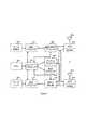
[0047]図1は、本発明の実施形態による基地局200の設計のブロック図を示す。基地局200は、MIMOワイヤレス送信のための標準的なモジュールを含む。 [0047] FIG. 1 shows a block diagram of a design of a
[0048]図1を参照すると、一実施形態において、基地局200にある送信プロセッサ215は、データ送信元210から1つ又は複数のユーザ機器(UE)のためのデータを受信し、各UEについてデータを処理し、データシンボルをすべてのUEに与える。プロセッサ215はまた、コントローラ/プロセッサ270からの制御情報も受信及び処理し、制御シンボルを与える。一実施形態において、プロセッサ270はまた、1つ又は複数の基準信号のための基準シンボルを生成する。一実施形態において、送信(TX)MIMOプロセッサ220が、各UEのためのデータシンボル、制御シンボル、及び/又は基準シンボル、並びに、同じ基地局200において配列されるか、又は、他の基地局、RRHなどのような他のワイヤレスエンティティに対する、アンテナのための基準信号に対するプリコーディングを実施する。 [0048] Referring to FIG. 1, in one embodiment, a transmit
[0049]一実施形態において、プロセッサ220は、変調器MOD230a〜230tに並列出力シンボルストリームを与えることができる。各変調器230は、当該技術分野において既知のように、出力サンプルストリームをさらに処理(たとえば、アナログに変換、増幅、フィルタリング、及びアップコンバート)してダウンリンク信号を得る。変調器230a〜230tからのダウンリンク信号はそれぞれ、アンテナ235a〜235tを介して送信される。 [0049] In one embodiment,
[0050]基地局200において、様々なUEからの、又は、同じ基地局200に配列されているか若しくは異なる基地局若しくは他のワイヤレスエンティティに位置する他のアンテナによるアップリンク信号が、アンテナ235a〜235tによって受信され、復調器(DEMOD230a〜230t)によって復調され得る。復調信号は、MIMO検出器240によって検出され、受信プロセッサ245によってさらに処理されて、UE及び他のワイヤレスエンティティによって送信された復号データ及び制御情報が得られる。受信プロセッサ245は、検出されたシンボルをMIMO検出器から受信し、復号データをデータシンク250に与え、制御情報をコントローラ/プロセッサ270に与える。DEMOD230a〜230tによって出力される復調信号も、チャネルプロセッサ280に与えられ、チャネルプロセッサにおいて、アップリンクチャネルが推定され、コントローラ/プロセッサ270に与えられる。 [0050] At
[0051]図1の基地局設計は、較正処理ユニット290をも含む。較正処理ユニットは、基地局200がアンテナ素子235a〜235tからのアップリンク受信信号を処理するときにはこれらの素子の各々と結合されているRF−ベースバンド変換ハードウェア(たとえば、利得制御装置、フィルタ、混合器、A/Dなど)によって導入される障害、及び、基地局200が基地局アンテナ素子235a〜235tによって送信されることになる信号を生成するときは各アンテナ素子235a〜235tに結合されているベースバンド−RF変換ハードウェア(たとえば、増幅器、フィルタ、混合器、A/Dなど)によって導入される障害を推定(及び場合によって補償)する役割を担う。一実施形態において、素子230aと素子235aとの組み合わせを単一の(較正されていない)送受信機ユニットとして考え、素子230a〜230tと、それらの素子のそれぞれの素子235a〜235tとのすべてのそのような組み合わせを個々の送受信機ユニットとして考察すると、較正プロセッサ290は、これらの送受信機ユニットのサブセットからの可逆性ベースのMU−MIMOを可能にするために使用されるこれらの送受信機ユニットのサブセットの相対較正のためのプロセスを実施する。一実施形態において、プロセッサ290は、コントローラ/プロセッサユニット270と制御情報を交換する。較正プロセッサ290は、たとえばArgos及びBursaliogluのような当該技術分野において既知の技法と本明細書に開示されている新規の技法との組み合わせを介して、コントローラ/プロセッサユニット270においてULチャネル推定値とともに、当該技術分野において既知のように1つ又は複数のUEのための1つ又は複数のプリコーディングベクトルを構築して(たとえばBursalioglu)、それらのベクトルをプリコーディングのためにTX MIMOプロセッサ220に与えるために使用することができる較正値を計算する。いくつかの実施形態において、プロセッサ290は、別個の基地局に接続されている送受信機ユニットの相対較正を補助するために、他の基地局によって受信及び/又は送信される信号を示す追加の情報を、他の基地局から与えられる。 [0051] The base station design of FIG. 1 also includes a calibration processing unit 290. The calibration processing unit is configured to transmit RF to baseband conversion hardware (eg, gain controller, filter, etc.) coupled to each of these elements when the
[0052]上記に記載されている実施形態は、少なくとも部分的に、処理ユニット290によって有効化され、較正のシグナリング及びデータ収集態様並びに本明細書に記載されている相対較正方法の両方を含み、これらの方法は、収集されるデータ、並びに、場合によっては、この基地局及び場合によっては他の基地局にある送信アンテナノードの任意のサブセットに関する過去の相対較正値を含む追加のパラメータに基づく。 [0052] The embodiments described above are validated at least in part by the processing unit 290, including both calibration signaling and data collection aspects and the relative calibration methods described herein; These methods are based on collected data and possibly additional parameters including past relative calibration values for any subset of transmit antenna nodes at this base station and possibly other base stations.
相対較正における多重化利得
[0053]較正シグナリングにおいて多重化利得を可能にし、より一般的に、較正シグナリングにおける多重化利得と相対較正品質(におけるダイバーシティ)とのトレードオフを可能にする新規の系統の相対較正プロトコルが、本明細書に開示されている。全体を通じて、較正は、T×N個の時間−周波数(TF)スロットのブロックに対して行われると仮定される。一実施形態において、Tはこれらのチャネルのコヒーレンス時間内にあり、また、較正される必要があるRF障害量のコヒーレンス時間内にもあると仮定される。同様に、Fはこれらのチャネルのコヒーレンス帯域幅であり、一方、較正される必要があるRF障害量のコヒーレンス帯域幅はN又はそれよりも高い。T、N、及びFを使用して、プロトコル系統はT、N、及びFの関数として記述される。Multiplexing gain in relative calibration
[0053] A new family of relative calibration protocols that enable multiplexing gains in calibration signaling and, more generally, allow a trade-off between multiplexing gains in calibration signaling and relative calibration quality (in diversity). It is disclosed in the specification. Throughout, it is assumed that calibration is performed on a block of T × N time-frequency (TF) slots. In one embodiment, T is assumed to be within the coherence time of these channels and also within the coherence time of the RF impairment amount that needs to be calibrated. Similarly, F is the coherence bandwidth of these channels, while the RF coherence bandwidth of the RF impairment that needs to be calibrated is N or higher. Using T, N, and F, the protocol family is described as a function of T, N, and F.
[0054]T×NブロックのTFスロットにわたるシグナリング及び較正プロトコルの適用を考察する。時刻F≧N(そのため、すべてのアクセスポイント(AP)間のチャネルはT×NブロックのTFスロットで一定のままである)について、先行する節において考察したシグナリングプロトコルを用いて、その間「すべての」チャネルが一定であるT×Nブロックの時間−周波数スロットを使用して、TN個のアンテナノードから成るアレイの相対較正を可能にすることができると仮定し、ここで、TNアンテナノードの各々は、個別のスロット(合計TN個のスロットの中から)を使用して、パイロットをブロードキャストする。加えて、各アンテナノードは、アンテナの単一のパイロットブロードキャストとは異なる時間インデックスを有するTFスロットにおいて発生するすべての他のパイロット送信(すなわち、合計で(T−1)N個のTFスロット)の間に観測値を収集する。その後、任意のT>1及び任意のN≧1について、先行する節の技法を用いてネットワークを較正することができる。同じことが、任意のF≧2について当てはまる。 [0054] Consider the application of signaling and calibration protocols over TF slots of T × N blocks. For the time F ≧ N (so the channel between all access points (AP) remains constant in TF slots of T × N blocks), using the signaling protocol discussed in the previous section, Suppose that a time-frequency slot of T × N blocks where the channel is constant can be used to allow relative calibration of an array of TN antenna nodes, where each TN antenna node Broadcast the pilot using individual slots (out of a total of TN slots). In addition, each antenna node is responsible for all other pilot transmissions that occur in TF slots that have a different time index than the single pilot broadcast of the antenna (ie, (T−1) N TF slots in total). Collect observations in between. The network can then be calibrated using the techniques of the preceding clause for any T> 1 and any N ≧ 1. The same is true for any F ≧ 2.
[0055]本発明の実施形態は、任意のT>2及び任意のTN>2について、T×Nブロックの時間−周波数スロット内でより大きいサイズのネットワークを較正するための方法を含む。実質的に、(T=2、N=1)の事例について、(参照されている方式におけるように)わずか2つの素子しか互いに対して較正することができないが、T>1での任意の他の(N,T)の組み合わせについて、参照方式よりも完全に大きいサイズを有するアレイを較正することができるプロトコルが存在する。 [0055] Embodiments of the present invention include a method for calibrating a larger size network within a time-frequency slot of TxN blocks for any T> 2 and any TN> 2. Effectively, for the case (T = 2, N = 1), only two elements can be calibrated against each other (as in the referenced scheme), but any other with T> 1 There are protocols that can calibrate arrays that have a size that is completely larger than the reference scheme for the (N, T) combinations.
[0056]最初に、N=1の事例(単一のOFDMトーンにわたってT個のTFスロットのブロックを含む)を考察する。そのような事例において、Tとともに二次的に増加するいくつかのノードを較正することが可能である。次に、F≧N、並びに、それによってArgos及びBursaliogluのベースライン方式と比較して大幅に改善する、較正されるノードの数がTとNの両方とともに二次的に増加する本発明のプロトコルを用いて、一般的な(N,T)の事例を考察する。最後に、F≦Nの事例を考察し、較正されるノードの数がTとともに二次的に増加し、積FNとともに線形的に増加するプロトコルを開示する。 [0056] Consider first the N = 1 case (including a block of T TF slots over a single OFDM tone). In such cases, it is possible to calibrate several nodes that increase quadratically with T. Next, the protocol of the present invention in which the number of nodes to be calibrated secondarily increases with both T and N, F ≧ N, and thereby greatly improved compared to the Argos and Bursalioglu baseline scheme Let us consider a general (N, T) case using. Finally, consider the case where F ≦ N, and disclose a protocol in which the number of calibrated nodes increases quadratically with T and increases linearly with product FN.
単一トーン較正:T個の時間スロットにわたるシグナリング及び較正
[0057]本明細書に記載されている較正プロトコルの実施形態は、以下の2つの事実を利用する。
1)集合{1,2,...,T}内のtに対するTFスロットにおいてパイロットが送信されると仮定すると、任意の所与の時刻t≧2について、アレイの(多素子)部分を、2つ又はそれ以上のスロットのセットにわたって較正することができる。
2)その時刻インスタンスのセットの間にブロードキャストされるパイロットに基づくアンテナアレイのそのような較正される部分を、同じパイロットからの較正されない部分の観測値とともに併せて利用して、較正における「多重化利得を得る」、すなわち、単一のチャネル使用(TFスロット)でアレイの(すでに)較正されている部分に対して複数のノードを較正することができる。Single tone calibration: signaling and calibration over T time slots
[0057] The calibration protocol embodiments described herein take advantage of the following two facts.
1) Set {1, 2,. . . , T}, calibrate the (multi-element) portion of the array over a set of two or more slots, for any given time t ≧ 2, assuming that pilots are transmitted in TF slots for t can do.
2) Utilizing such a calibrated part of a pilot-based antenna array broadcast during that set of time instances together with observations of the uncalibrated part from the same pilot, Gain is obtained, ie, multiple nodes can be calibrated against the (already) calibrated part of the array with a single channel usage (TF slot).
予め較正済みのアレイによる相対較正の多重化利得
[0058]開示されている新規の系統の較正プロトコルを説明する前置きとして、最初に、上記項目(b)を詳細に考察する。複数の素子が、単一の追加のパイロット送信で、予め較正済みの「基準」アレイに対して同時に較正されることになる単一の多素子較正事例を考察する。インデックスj=0を有するアレイはM0=M>1個の素子を有し、一方で、j>0について、Mj≧1個の素子から成るアレイはすでに較正されており、すなわち、そのアレイの素子は、(たとえば、先行する較正シグナリングに基づいて)互いに対して相対的に較正されており、
j≧0について Rj=AjTjcj (3)
Mj×Mj複素数値対角(可逆)行列Tj及びRjがそれぞれ(未知の)送信機RF障害及び受信機RF障害を表す場合、cjは未知の(非ゼロ)複素スカラーであり、Ajは、j番目のアレイの素子の(先行する)相対較正の効果をあらわす既知の対角(可逆)行列である、と仮定する。Relative calibration multiplexing gain with pre-calibrated array
[0058] As a prelude to describing the new family of calibration protocols disclosed above, item (b) above is first considered in detail. Consider a single multi-element calibration case where multiple elements will be simultaneously calibrated against a pre-calibrated “reference” array with a single additional pilot transmission. An array with index j = 0 has M0 = M> 1 elements, whereas for j> 0, an array of Mj ≧ 1 elements has already been calibrated, ie the array Of the elements are calibrated relative to each other (eg, based on previous calibration signaling),
For j ≧ 0 Rj = Aj Tj cj (3)
Cj is an unknown (non-zero) complex scalar, where Mj × Mj complex-valued diagonal (reversible) matrices Tj and Rj represent (unknown) transmitter and receiver RF impairments, respectively. , Aj is assumed to be a known diagonal (reversible) matrix representing the effect of the (preceding) relative calibration of the elements of the jth array.
[0059]H0jが、各々分散σh2(j)を有し、σh2(j)>0である、独立で同一の分布に従う(iid)複素数値ガウスゼロ平均エントリから構成されるアンテナアレイ0〜アレイjのMj×M物理チャネル行列を示すものとする。逆チャネルを記述するM×Mjチャネル行列がHj0として示され、このチャネルのコヒーレンス時間及び帯域幅の中ですべてのシグナリングが行われると仮定する。したがって、チャネル可逆性に起因して、H0j=[Hj0]Tである。[0059] Antenna array 0 to array j consisting of complex-valued Gaussian zero mean entries, where H0j each has a variance σh2 (j) and σh2 (j)> 0, and follows an independent and identical distribution (iid)Let Mj × M physical channel matrix be denoted.Assume that the M × Mj channel matrix describing the reverse channel isdenoted as Hj0 and that all signaling takes place within the coherence time and bandwidth of this channel. Therefore, H0j = [Hj 0] T due to channel reversibility.
[0060]加えて、j≧1について、各々が以下の形態のMj×L行列内にある、0番目のアンテナアレイによって送信されるパイロットからのj番目のアレイにおける観測値が利用可能であると仮定される。
Yj=RjH0T0P+Zj (4)
式中、Pは、L≦M個の線形独立な列(各列がパイロットビームを表す)を有する既知のM×L行列であり、{Zj}’は独立した雑音行列であり、Zjは、分散σz2(j)を有する互いに独立で同一の分布に従うガウスゼロ平均エントリを有する。[0060] In addition, for j ≧ 1, observations in the j th array from pilots transmitted by the 0 th antenna array are available, each in an Mj × L matrix of the form Is assumed.
Yj = Rj H0 T0 P + Zj (4)
Where P is a known M × L matrix with L ≦ M linearly independent columns (each column represents a pilot beam), {Zj } ′ is an independent noise matrix, and Zj Have Gaussian zero mean entries that follow each other and have the same distribution with variance σz2 (j).
[0061]単一チャネル使用において、所与のパイロット集合{vj}、vjは任意の非ゼロベクトル、の集合{1,2,...,K}内のj個のインデックスを有するすべてのK個の要素からの単一の同時単一パイロット送信を考察する。そのような事例において、ゼロ番目のアレイは、以下の基準アレイの形態におけるM×1観測値ベクトルを収集する。
式中、z0は、指数σz2(0)を有するゼロ平均ガウスエントリを有する、互いに独立で同一の分布に従う雑音ベクトルである。[0061] In single channel use, a given set of pilots {vj }, vj is an arbitrary non-zero vector set {1, 2,. . . , K} consider a single simultaneous single pilot transmission from all K elements with j indices in. In such cases, the zeroth array collects M × 1 observation vectors in the form of the following reference array.
Where z0 is a noise vector that has zero mean Gaussian entries with exponent σz2 (0), independent of each other and following the same distribution.
[0062]その後、集合{0,1,2,...,K}内のj個のインデックスを有するすべてのアレイの共同相対較正、すなわち、上記1≦j≦Kについての観測値y0及びYjに基づく、0≦j≦Kについての相対較正条件のセットを利用しながらの、1≦j≦Kについてのcj/c0の推定を考察する。また、基準アレイは、基準アレイの相対較正の効果を表す、既知の対角(可逆)行列によって(4)を満たすと仮定する。このとき、K≦Lの場合且つその場合に限り、基準アレイに対するK個のアンテナ素子の相対較正が可能である。特に、cj=rj/tjとし、雑音のない状態で(σz2−>0)、K≦Lの場合且つその場合に限り、確率1でcj/c0を得ることが可能である。[0062] Then, the set {0, 1, 2,. . . , K} of the joint relative calibration of all arrays with j indices, ie, relative calibration conditions for 0 ≦ j ≦ K based on observations y0 and Yj for 1 ≦ j ≦ K above. Consider the estimation of cj / c0 for 1 ≦ j ≦ K using a set. It is also assumed that the reference array satisfies (4) with a known diagonal (reversible) matrix that represents the relative calibration effect of the reference array. At this time, relative calibration of the K antenna elements with respect to the reference array is possible only when K ≦ L. In particular, it is possible to obtain cj / c0 with probability 1 only when cj = rj / tj and no noise (σz2- > 0) and K ≦ L. It is.
[0063]次に、そのような相対較正が可能である、すなわち、K≦Lである限り、確率1で、雑音のない状態でcj/c0を得ることが可能であることが示される。特に、以下の量を考察する。
式中、ejはK×K単位行列の第j列を示し、
は、
によって与えられる。[0063] Next, it is shown that such relative calibration is possible, that is, as long as K ≦ L, it is possible to obtain cj / c0 with no probability and without noise. . In particular, consider the following quantities:
Where ej represents the j th column of the K × K identity matrix,
Is
Given by.
[0064]次に示すように、雑音のない状態で、上記式(6)の量は、(確率1で)cj/c0に等しい。この目的に向けて、以下の量
は、適切に選択されたdj及びfjについて、(雑音のない状態で)cj/c0に等しくすることができることを示す。最初に、式(4)を、式(3)を用いて以下のように書き直すことが好都合である。
式中、Gjは、
Gj=TjH0jT0P (10)
の最大階数Mj×L行列である。[0064] As shown below, in the absence of noise, the quantity of equation (6) above is equal to cj / c0 (with probability 1). For this purpose, the following quantity
Indicates that for properly chosen dj and fj , it can be equal to cj / c0 (without noise). First, it is convenient to rewrite equation (4) using equation (3) as follows:
Where Gj is
Gj = Tj H0j T0 P (10)
Is the maximum rank Mj × L matrix.
[0065]また、
も定義され、Qは階数min(L,K)を有することに留意されたい。式(5)の両辺の
による残された操作(A0は可逆的であるため、これは明確に定義された演算である)、並びに、式(3)、(10)及び(11)を使用して、
が、もたらされる。[0065] Also,
Note that Q has a rank min (L, K). On both sides of equation (5)
Using the remaining operation by (which is a well-defined operation because A0 is reversible) and using equations (3), (10) and (11),
Is brought about.
[0066]さらに、式(7)の
の式において、式(9)の
の式を置換し、式(11)を使用して
が、もたらされる。[0066] Further, in formula (7)
In the formula (9)
Using the formula (11)
Is brought about.
[0067]したがって、選択
について、式(8)の量|jは、雑音のない状態で、
になる。[0067] Therefore, select
For quantity |j in the absence of noise,
become.
[0068]次に、k≦jについてすべてのqkに直交するという特性を有する任意の非ゼロベクトルfjを選択することによって、所望の量cj/c0がもたらされることに留意されたい。そのようなベクトルfjは、K≦Lである限り、(確率1で)存在する。Qは直に利用可能ではないが、このゼロ強制特性によってfjを選択することは依然として可能である。この目的に向けて、k1≧k2のk1×k2最大階数行列Wを与えられると、Wの疑似逆Pinv−norm(W)は、単位ノルム行を有するものとして示される、すなわち、(WHW)−1WHとして示されるが、その行は、単位ノルムを有するように再スケーリングされている。F=[f1 f2 L fk]Hとし、Fは以下のように選択される。
式中、
は式(7)によって与えられ、K≦Lを条件として疑似逆が存在する。式(13)に起因して、雑音がない状態で、
が得られ、それゆえ、
となる。結果として、上記のFの選択について、式(14)の量|jは所望のように、確率1でcj/c0に等しい。このdj及びfjの選択について、式(8)の量|jは、式(6)の式にも等しいことも容易に示され得る。[0068] Next, note that selecting any non-zero vector fj that has the property of being orthogonal to all qk for k ≦ j yields the desired quantity cj / c0. . Such a vector fj exists (with probability 1) as long as K ≦ L. Although Q is not directly available, it is still possible to select fj with this zero forcing property. To this end, given a k1 × k2 maximum rank matrix W with k1 ≧ k2 , the pseudo inverse Pinv-norm (W) of W is shown as having unit-norm rows, ie , (WH W)−1 WH , the row has been rescaled to have a unit norm. Let F = [f1 f2 L fk ]H, and F is selected as follows:
Where
Is given by equation (7), and there is a pseudo-inversion with K ≦ L as a condition. Due to equation (13), in the absence of noise,
And hence
It becomes. As a result, for the above selection of F, the quantity |j in equation (14) is equal to cj / c0 with probability 1 as desired. For this selection of dj and fj , it can easily be shown that the quantity |j in equation (8) is also equal to the equation in equation (6).
[0069]{1.2....,L}の集合内のKの異なる選択は、較正の「ダイバーシティ」の形で較正の「多重化利得」(すなわち、単一のパイロット送信によって較正されるアンテナの数)とのトレードオフになることに留意されたい。このダイバーシティ効果は、式(3)〜(5)のセットによって記述される設定が、厳密にL未満であるKとともに考えられるときに、受信ビーム形成利得の形で顕著である。この事例において、K<L個の未較正アンテナ(各較正済みアンテナからのもの)が、パイロットを同時に送信する。j番目のアレイを0番目のアレイに対して較正するのに使用される疑似逆ベースのフィルタfjは、
の構造によって成立する。[0069] {1.2. . . . , L}, a different choice of K in the set of calibration “diversity” trades off the calibration “multiplexing gain” (ie, the number of antennas calibrated by a single pilot transmission). Please note that. This diversity effect is significant in the form of receive beamforming gain when the settings described by the set of equations (3)-(5) are considered with K being strictly less than L. In this case, K <L uncalibrated antennas (from each calibrated antenna) transmit pilots simultaneously. The pseudo inverse based filter fj used to calibrate the j th array with respect to the 0 th array is
It is established by the structure of
[0070]それゆえ、j番目のアレイの較正において、L個の利用可能な次元の中からK−1次元が、y0からすべての他のパイロットの応答(j番目のアレイからのものに加えて)をゼロ強制するのに使用される。したがって、受信ビーム形成フィルタfjは、(同時に較正される他のK−1個のアレイによって同時に送信される)残りのK−1個のパイロットに対する0番目のアレイ応答が及ぶ空間の(L−K+1次元)ゼロ空間内にある。その結果、疑似逆ベースのフィルタfjは、実質的に、この部分空間において受信アンテナビーム形成を実施し、次数L−k+1(K<Lの場合に1よりも大きい)の受信ビーム形成利得を得るということになる。[0070] Therefore, in the calibration of the j th array, the K−1 dimension out of the L available dimensions is added from y0 to the response of all other pilots (in addition to those from the j th array). Used to force zero). Thus, the receive beamforming filter fj is (L−) of the space spanned by the 0th array response for the remaining K−1 pilots (transmitted simultaneously by other K−1 arrays calibrated simultaneously). K + 1 dimension) in zero space. As a result, the pseudo-inverse-based filter fj substantially performs receive antenna beamforming in this subspace and has a receive beamforming gain of order L−k + 1 (greater than 1 when K <L). It will be obtained.
[0071]多重化利得は、M≧L>1を条件とした較正において可能であり(すなわち、K>1)、これは、すべてのj>1についてMj=1であっても可能である。事実、Mjは、この節における「単一チャネル使用」パイロット送信によってもたらされる多重化利得において何の役割も果たさない。より大きいアレイ、すなわち、Mj>1は、パイロット送信に送信ビーム形成効果を利用することによって、この較正技法に雑音排除性をもたらすために使用することができる。[0071] Multiplexing gain is possible in calibration subject to M ≧ L> 1 (ie, K> 1), which is possible even with Mj = 1 for all j> 1. . In fact, Mj plays no role in the multiplexing gain provided by the “single channel use” pilot transmission in this section. Larger arrays, ie Mj > 1, can be used to bring noise immunity to this calibration technique by exploiting the transmit beamforming effect for pilot transmission.
大規模較正問題の文脈における同時較正
[0072]先行する節部分における較正方式は、階層較正を含む大規模較正問題の文脈に容易に使用することができる。たとえば、所与の時点において複数の「0番目の」アレイが存在する、すなわち、式(3)〜(4)に与えられている形式の条件セットが、予め較正済みの(0番目の)アレイと集合{j}j>0内のインデックスを有するアレイ(又はノード)のサブセットとの間で当てはまる場合があるシナリオがある。そのような事例において、パイロットの同時送信は、各「0番目の」アレイにおいて、個々に送信ノードのセットによって各アレイを個々に較正するのに使用することができる式(5)に与えられている形式の観測値をもたらす。しかしながら、これらの測定値はまた、より大きい較正の問題を解決するために組織的にともに使用することもできる。Simultaneous calibration in the context of large-scale calibration problems
[0072] The calibration scheme in the preceding clause section can be easily used in the context of large-scale calibration problems involving hierarchical calibration. For example, there are a plurality of “0th” arrays at a given time, ie, a condition set of the type given in equations (3)-(4) is a pre-calibrated (0th) array. There are scenarios that may apply between and a subset of an array (or node) with an index in the set {j}j> 0 . In such cases, the simultaneous transmission of pilots is given in equation (5), which can be used to individually calibrate each array by a set of transmitting nodes individually in each “0th” array. Result in the form of observations. However, these measurements can also be used together systematically to solve larger calibration problems.
[0073]これを例示するために、|jを以下のように、式(6)にある形式から式(8)にある形式に表現し直すことを考察する。
式中、
ここで、
は式(15)のFのj番目の行を示す。また、式(12)及び(13)を使用して、以下の式が得られる。
式中、
である。[0073] To illustrate this, consider re-expressing |j from the form in equation (6) to the form in equation (8) as follows.
Where
here,
Indicates the jth row of F in equation (15). Moreover, the following formula | equation is obtained using Formula (12) and (13).
Where
It is.
[0074]式(1)と式(16)とを比較することによって、fjが式(15)に従って選択されることを条件とし、観測値セットYjが十分に高い品質のものであることを条件として、式(1)の形式の観測値対を使用して式(2)の形式のLS費用関数を形成することができるのと同じように、式(16)の形式の観測値対を使用して相対較正のためのLS費用関数を形成することができることが明らかになる。[0074] The observation set Yj is of sufficiently high quality, provided that fj is selected according to Equation (15) by comparing Equation (1) with Equation (16). As long as an LS cost function in the form of Equation (2) can be formed using an observation pair in the form of Equation (1), Can be used to form an LS cost function for relative calibration.
[0075]単純な例として、i=1,2,...,Dで(0,i)としてインデックス付けされている、D>1の予め較正済みのM次元アレイを含む場合を考察する。j≧1でインデックス付けされているK個のノードが、パイロット次元L≦Mを有するこれらのD個のアレイの各々からのパイロット観測値を有すると仮定する。K≦Lでのインデックス
を有するノードからの単一の同時パイロット送信は、DM次元アレイ及びK個の送信ノードを含むアレイを較正するのに十分である。特に、アンテナアレイ(0,i)における観測値を、K個のノードにおける観測値と組み合わせて、式(16)の形態の実効的なK対の観測値を得ることができ、各対は、個別のパイロット送信ノードj及びアレイ(0,i)に対応する。
が、ノードj及びアレイ(0,i)と関連付けられるそのような観測値の対を示すものとすると、このとき、観測値対の集合
を使用して、式(2)の形式のLS費用関数を設定することができる。[0075] As a simple example, i = 1, 2,. . . , D, including a pre-calibrated M-dimensional array indexed as (0, i) with D> 1. Suppose that the K nodes indexed with j ≧ 1 have pilot observations from each of these D arrays with pilot dimension L ≦ M. Index with K ≦ L
A single simultaneous pilot transmission from a node with s is sufficient to calibrate a DM-dimensional array and an array containing K transmitting nodes. In particular, the observations at antenna array (0, i) can be combined with the observations at K nodes to obtain effective K pairs of observations in the form of equation (16), where each pair is Corresponding to individual pilot transmission node j and array (0, i).
Denote such a pair of observations associated with node j and array (0, i), then a set of observation pairs
Can be used to set the LS cost function in the form of equation (2).
[0076]式(16)のランダム変数の影響力を理解するために、M=L、P=I、AjAjH=I、|cj/c0|=1、
、且つvjが1の値を有する1つの非ゼロ要素を有するベクトルである特別な事例を考察する。このとき、
となる。[0076] To understand the influence of the random variables in equation (16), M = L, P = I, Aj Aj H = I, | cj / c0 | = 1,
Consider the special case where vj is a vector with one non-zero element having a value of one. At this time,
It becomes.
[0077]式(15)に起因して、k≠jについて、式(13)とともに
をもたらし、
の指数を有する
が得られる。m≠kについて
が独立であることにも留意することによって、式(17)において
がもたらされる。さらに、
及びTjTjH=Iを仮定すると、十分に大きいSNR
について、
になる。[0077] Due to Equation (15), for k ≠ j, along with Equation (13)
Brings
Has an index of
Is obtained. About m ≠ k
In the equation (17) by also noting that
Is brought about. further,
And Tj Tj H = I, a sufficiently large SNR
about,
become.
[0078]式(17)及び(18)から、式(16)の形式の較正観測値対におけるSINR(信号対干渉雑音比)が(L−K+1)/Kとしてスケーリングする、すなわち、予測されるように、多重化利得Kが高くなるほど、実効的なSINRが低くなることを観察することができる。 [0078] From equations (17) and (18), the SINR (signal-to-interference and noise ratio) in a calibration observation pair of the form of equation (16) scales as (L−K + 1) / K, ie is predicted. Thus, it can be observed that the effective SINR decreases as the multiplexing gain K increases.
単一トーン較正:T個のチャネル使用にわたるシグナリング及び較正
[0079]先行する節の知見を使用して、サイズがTとともに二次的に増加するアレイを較正することを可能にする、パイロットシグナリング及び較正アルゴリズムを含む、このための較正方式が記載される。固定セットの較正パイロットチャネル使用Tを受けて、較正済みアレイのサイズを最大化することに焦点を当てるそのようなプロトコルを考察する。プロトコルは、2つのチャネル使用を介して2素子アレイを較正することによって開始し(各チャネルは素子の1つによって使用されパイロットをブロードキャストする)、その後、多素子パイロット送信及びアレイのすでに較正された部分に対する反復的較正に依拠することによって、較正済みアレイのサイズを反復的に増大させる。Single tone calibration: signaling and calibration over T channel usage
[0079] A calibration scheme for this is described, including pilot signaling and a calibration algorithm that allows to calibrate an array whose size increases secondarily with T using the findings of the preceding section. . Given such a fixed set of calibration pilot channel usage T, consider such a protocol that focuses on maximizing the size of the calibrated array. The protocol starts by calibrating a two-element array via two channel usage (each channel is used by one of the elements to broadcast a pilot), then multi-element pilot transmission and array already calibrated By relying on iterative calibration on the part, the size of the calibrated array is iteratively increased.
[0080]一般性を損なうことなく、反復的較正プロセスを、パイロットブロードキャスト時間インデックスtと「位置合わせ」することができる。プロトコルに従って、最初の2つの時間スロットにおいて、2つの個別のアンテナ、たとえば、1及び2が、一度に1つの較正パイロットをブロードキャストする。互いのパイロットの観測値が、素子1及び2から構成される2次元アレイに対する較正を可能にする。スロット1及び2においてブロードキャストされたパイロットに基づいて、他のすべてのアンテナ素子が利用可能な観測値を有することに留意されたい。結果として、スロット3において、パイロットを同時に送信することによって、もう2つのアンテナ素子を較正することができ、それによって、時間1、2、及び3におけるパイロットブロードキャストに基づいて4次元較正済みアレイがもたらされる。これは、すべてのj≧1、L=2及びP=Iについて、M=2、Mj=1で式(3)〜(5)によって記述されているシナリオが存在するためであり、したがって、2次元アレイ{1,2}に対する別のK≦L=2個のアンテナの較正が、単一のパイロット送信によって可能である。この結果として、3回のパイロット送信で4素子アレイの較正がもたらされる。[0080] Without loss of generality, the iterative calibration process can be "aligned" with the pilot broadcast time index t. According to the protocol, in the first two time slots, two separate antennas, eg 1 and 2, broadcast one calibration pilot at a time. The observations of each other's pilots allow calibration for a two-dimensional array composed of elements 1 and 2. Note that based on the pilots broadcast in slots 1 and 2, all other antenna elements have available observations. As a result, two antenna elements can be calibrated by transmitting pilots simultaneously in
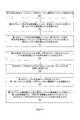
[0081]そのような4素子アレイの較正を可能にする一実施形態の流れ図を図2に示す。図2を参照すると、最初に、送信アンテナ(TXA)1が、パイロット(3001)を送信し、一方で、TXA2、3、4は、このパイロット(それぞれ3002、3003、及び3004)に応答して観測値を収集する。その後、TXA2が、パイロット(3102)を送信し、一方で、TXA1、3、4は、このパイロット(それぞれ3101、3103、及び3104)に応答して観測値を収集する。最後に、TXA3及びTXA4がパイロット(それぞれ3203及び3204)を同時送信し、一方で、TXA1及び2は、この同時パイロット送信(それぞれ3201及び3202)に応答して観測値を収集する。次に、すべての送信アンテナが、それらの観測値(K=1、2、3、4について330k)をコントローラに与える。コントローラは、すべての観測値を収集する(340)。その後、コントローラは、相対較正を実施して、すべてのアンテナについての較正調整値を計算する(350)。特に、利用可能な観測値3002及び3101を使用して、コントローラは、たとえば、当該技術分野において既知であるBursalioglu又はArgosにおける方法を使用することによって、TXA1及び2を較正して2次元アレイにする。その後、コントローラは、残りの観測値を使用して、本明細書に開示されている方法を用いて(たとえば、式(14)において各々のlj、jは較正されているアンテナのインデックス、を計算することによって)TXA3及び4を、{1,2}アレイに対して較正する。その後、コントローラは、較正調整値(360)をすべてのTXAにわたす。各TXAは、それ自体の調整値(K=1、2、3、4について370k)を受信し、必要とされる較正を実施する。[0081] A flow diagram of one embodiment that enables calibration of such a four-element array is shown in FIG. Referring to FIG. 2, first, transmit antenna (TXA) 1 transmits a pilot (3001 ), while TXA2 ,3 ,4 transmit this pilot (3002 , 3003 , and 3004 , respectively). Collect observations in response to. TXA2 then transmits a pilot (3102 ), while TXA1,3 ,4 collect observations in response to this pilot (3101 , 3103 , and 3104 , respectively). Finally, TXA3 and TXA4 simultaneously transmit pilots (3203 and 3204 respectively), while TXA1 and 2 collect observations in response to this simultaneous pilot transmission (3201 and 3202 respectively). . All transmit antennas then give their observations (330k for K = 1, 2, 3, 4) to the controller. The controller collects all observations (340). The controller then performs a relative calibration to calculate calibration adjustment values for all antennas (350). In particular, using the
[0082]動作300、310、320の順序は必須ではないことに留意されたい。すなわち、動作320が310及び/又は300の前に来てもよく、310が300の前に来てもよい。重要な要素は、すべてのこれらの送信が、それにわたってアンテナTX1〜TX4の間のすべてのポイント間チャネルが実質的に一定である独立したリソースにおいて行われることである。また、TX1及びTX2を含む2次元アレイの較正は、動作300及び310が行われた後の任意の時点(たとえば、動作320の前、320と同時、又は320の後)において達成することができ、一方で、アレイ全体は、集合{300、310及び320}内のすべての動作が行われた後にのみ較正することができることも留意されたい。 [0082] Note that the order of
[0083]一実施形態において、プロセスは、5個以上の素子を有するアレイを較正するように拡張される。たとえば、最初の3回のパイロット送信の間により多くのアンテナが観測値を収集する、先行するプロトコルの拡張が考慮される場合。したがって、時間スロット4において、予め構成済みの4次元アレイ{1,2,3,4}に対する較正の問題がある。3つの線形独立ビームからの3つのパイロットが残りの(未較正)素子の各々によって観測されていることを前提として、状況は、M=4、
及び、L=3での式(3)〜(5)によって記述される。[0083] In one embodiment, the process is extended to calibrate an array having five or more elements. For example, if an extension of the preceding protocol is considered where more antennas collect observations during the first three pilot transmissions. Thus, in time slot 4, there is a calibration problem for the preconfigured four-dimensional array {1, 2, 3, 4}. Given that three pilots from three linear independent beams are being observed by each of the remaining (uncalibrated) elements, the situation is M = 4,
And described by equations (3)-(5) at L = 3.
[0084]それゆえ、単一のパイロット送信(スロット4における)で、もうK=L=3個のアンテナを較正することができ、4チャネルを較正パイロットに使用して、全体で7素子較正済みアレイがもたらされる。一般的な事例において、k番目のスロット送信の前に、すでに較正済みの素子からの、k−1個の線形独立ビーム上のk−1個のパイロットからの観測値が、各未較正素子にとって利用可能である。これによって、これらの素子のうちの(最大)もうk−1個を、すでに較正済みのアレイに対して較正することができる。結果として、時刻Tにおいて、この方式による較正済みアレイのサイズは、
によって与えられる。[0084] Therefore, with a single pilot transmission (in slot 4), another K = L = 3 antennas can be calibrated and a total of 7 elements calibrated using 4 channels for the calibration pilot An array is provided. In the general case, prior to the kth slot transmission, observations from k−1 pilots on k−1 linearly independent beams from already calibrated elements are for each uncalibrated element. Is available. This allows (maximum) another k-1 of these elements to be calibrated against an already calibrated array. As a result, at time T, the size of the calibrated array according to this scheme is
Given by.
[0085]上記プロトコルは好都合には、T列パイロット行列P(T)を介して表現することができ、P(T)の(i,t)番目の要素が、時刻tにおいてアンテナiによってブロードキャストされるパイロットのパイロットスケーリング係数を示すように(また、ゼロ値が、アンテナiが時刻tにおいてパイロットをブロードキャストしていないことを暗示するように)定義することができる。このプロトコルの行列P(t)は、再帰的に記述することができ、すなわち、P(1)=1が得られ、一方で、任意の時刻t>1において、パイロット行列P(t)は、
を満たす。[0085] The above protocol can conveniently be expressed via a T-sequence pilot matrix P (T), where the (i, t) th element of P (T) is broadcast by antenna i at time t. Can be defined to indicate the pilot scaling factor of the pilot (and also imply that antenna i is not broadcasting the pilot at time t). The matrix P (t) of this protocol can be described recursively, ie P (1) = 1 is obtained, while at any time t> 1, the pilot matrix P (t) is
Meet.
[0086]{1,2,...,T}内の各tにおけるこのプロトコルの較正効率を表1に示す。
T個の時間スロットチャネル使用によるN個のトーンにわたるシグナリング及び較正
[0087]本発明の実施形態は、T×Nブロックの時間−周波数スロットにわたるシグナリング及び較正プロトコルを含む。T及びNはそれぞれ、チャネルコヒーレンス時間及び帯域幅内にあり、すべての(未知の)TX/RX RFチェーン障害係数は、T×Nブロックの時間−周波数スロットにわたって一定であると仮定する。各アンテナが単一のTFスロットにわたって単一のパイロットをブロードキャストする事例に焦点を当てる。各APアンテナは、そのパイロットブロードキャストのためのアンテナによっても使用されるTFと同じ時間インデックスを有するN個のTFスロットを除くすべてのTFスロットを「リスン」することができる。Signaling and calibration over N tones using T time slot channels
[0087] Embodiments of the present invention include signaling and calibration protocols over time-frequency slots of TxN blocks. Assume that T and N are within the channel coherence time and bandwidth, respectively, and that all (unknown) TX / RX RF chain impairment factors are constant over a time-frequency slot of T × N blocks. Focus on the case where each antenna broadcasts a single pilot over a single TF slot. Each AP antenna can “listen” for all TF slots except N TF slots that have the same time index as the TF also used by the antenna for its pilot broadcast.
[0088]これらの制約を前提として、反復的較正方式を、較正済みアレイのサイズが反復的に増大するように構築することができる。これらの方式は、TFスロットインデックスのマッピングを利用する。先行する節とほぼ同様に、すでに較正済みのアンテナ素子セットに対してKm個の素子を較正することを可能にすることを目標として、Km個のパイロットがインデックスmにおいて送信される。アンテナがそれ自体のパイロットをブロードキャストするときに他のトーンパイロット送信に対して「聴取(listen in)」することができないという事実を考慮に入れて、(T個のチャネル使用後に)較正済みアレイのサイズを最大化することを可能にするマッピングは以下によって与えられ、
m(t,n)−(n−1)T+t
一方で、対応する(可能性のある最大の)Km値は表2に示されている。
m (t, n)-(n-1) T + t
On the other hand, the corresponding (maximum possible) Km values are shown in Table 2.
[0089]このプロトコルは、一連のサイズを計算することができる。
このサイズは、NとTの両方において二次的である。[0089] This protocol can calculate a range of sizes.
This size is secondary in both N and T.
[0090]プロトコルはまた、経時的に連続的に較正を実施し(すなわち、一度にN個の時間−周波数スロットに基づいて)、また、サイズがN及びTとともに二次的に増加するアレイを較正することもできるように設計することもできる。この事例において、時間−周波数スロットの、反復較正ラウンドへのマッピングは、以下によって与えられる。
m(t,n)−t
1つのそのようなプロトコルのKm(又はこの事例ではKt)が表3に示されている。この事例について、2つの最初の時間インデックスの各々における最初のN個の時間−周波数スロットの各々において、N個の個別のアンテナが、較正パイロットを送信する。2つの時間スロットの後、2N個の素子から成るネットワークを、上述した相対較正技法を用いて上述のように較正することができる。一実施形態において、2N個のアンテナは、最初の2つのN次元OFDMシンボルにおいて、分離されているパイロットを送信している。各アンテナは、単一の所与の(時間−周波数)リソース要素においてパイロットを送信し、アンテナが送信したものからの異なる時間インデックスを有する(時間−周波数)リソース要素に対応するN個のリソース要素からすべてのパイロットを受信する。一実施形態において使用される較正方法は、Bursaliogluにおいて開示されているものである。加えて、2つの時間スロットの後、すべての残りの未較正素子の各々は、較正済み2N次元(「基準」)アレイからの、L=2N(線形独立)パイロットビーム上の利用可能な2N個の観測値を有する。結果として、時刻t=3において、各トーン上でK=L=2N個の素子を較正する単一のTFスロット内でパイロットを同時に送信し、本明細書に開示されている技法(たとえば、式(14))を使用することができ、サイズ2N+2N2の較正済みアレイがもたらされる。時刻t=4において、各未較正素子は、2N+2N2の予め較正済みのアレイ上で3N個の(線形独立)パイロットからの利用可能な観測値を有する。L=3N個の線形独立ビームからの3N個のパイロットが残りの素子の各々によって観測されていることを前提として、状況は、M=2N+2N2、j>1についてMj=1、及びL=3Nでの式(3)〜(5)に記載されているようなものである。結果として、時刻t=4において各トーン上でK=L=3N個の素子を較正する(パイロットを同時に送信する)ことができ、合計サイズが2N+2N2+3N2素子の較正済みアレイがもたらされる。同様に、時刻t=k≧3において、各未較正素子は、M≧Lで予め較正済みのアレイ上で3N個のL=(k−1)N個の(線形独立)パイロットからの利用可能な観測値を有する。結果として、時刻t=kにおいて各トーン上でもうK=L=(k−1)N個の素子を較正する(パイロットを同時に送信する)ことができる。全体で、T>1でT×Nブロックの時間−周波数スロット中に、この方式による最大サイズの較正済みアレイのサイズが、
によって与えられる。[0090] The protocol also performs continuous calibration over time (ie, based on N time-frequency slots at a time), and an array whose size increases quadratically with N and T. It can also be designed to be calibrated. In this case, the mapping of time-frequency slots to iterative calibration rounds is given by:
m (t, n) -t
The Km (or Kt in this case) for one such protocol is shown in Table 3. For this case, N individual antennas transmit calibration pilots in each of the first N time-frequency slots in each of the two first time indexes. After two time slots, a 2N element network can be calibrated as described above using the relative calibration technique described above. In one embodiment, 2N antennas transmit separated pilots in the first two N-dimensional OFDM symbols. Each antenna transmits a pilot in a single given (time-frequency) resource element and N resource elements corresponding to (time-frequency) resource elements having different time indexes from those transmitted by the antenna Receive all pilots from The calibration method used in one embodiment is that disclosed in Bursalioglu. In addition, after two time slots, each of all remaining uncalibrated elements is available 2N on the L = 2N (linearly independent) pilot beam from a calibrated 2N dimensional (“reference”) array. Have observations. As a result, at time t = 3, pilots are transmitted simultaneously in a single TF slot that calibrates K = L = 2N elements on each tone, and the techniques disclosed herein (eg, equations (14)) can be used, resulting in a calibrated array of size 2N + 2N2. At time t = 4, each uncalibrated element has available observations from 3N (linearly independent) pilots on a 2N + 2N2 pre-calibrated array. Given that 3N pilots from L = 3N linearly independent beams are observed by each of the remaining elements, the situation is that Mj = 1 for M = 2N + 2N2 , j> 1, and L = As described in formulas (3) to (5) with 3N. As a result, K = L = 3N elements can be calibrated (transmit pilots simultaneously) on each tone at time t = 4, resulting in a calibrated array with a total size of 2N + 2N2 + 3N2 elements. Similarly, at time t = k ≧ 3, each uncalibrated element is available from 3N L = (k−1) N (linearly independent) pilots on a pre-calibrated array with M ≧ L. Have a good observation. As a result, another K = L = (k−1) N elements can be calibrated (transmit pilots simultaneously) on each tone at time t = k. Overall, during a time-frequency slot of T> 1 and T × N blocks, the size of the maximum size calibrated array according to this scheme is
Given by.
[0091]各時間−周波数スロットにおけるこのプロトコルの較正効率を表3に示す。
[0092]前述した多重化利得対受信ビーム形成利得のトレードオフに関して説明すると、多重化利得を較正ダイバーシティとトレードオフする系統の較正シグナリング及び推定方式が存在する。特に、任意の時刻t≧3において、1≦Kt≦(t−1)Nで、Kt個の個別の未較正アンテナが、各時間−周波数スロット内で同時に送信する。これらの方式の多重化利得ダイバーシティトレードオフを表4に示す。1つの興味深い特別な事例は、各時間スロットにおいてダイバーシティ次数Nをもたらすことを含む。その興味深い事例において、時刻tにおける各TF周波数スロットにおいて、Kt個の送信アンテナ(TXA)がパイロットを同時に送信し、ここで、Ktは、
t>1についてKt=(t−2)N+1
によって与えられる。[0092] Referring to the aforementioned multiplexing gain versus receive beamforming gain tradeoff, there exists a system of calibration signaling and estimation schemes that tradeoff multiplexing gain with calibration diversity. In particular, at any time t ≧ 3, with1 ≦ K t ≦ (t- 1) N, K t pieces of individual uncalibrated antenna, each time - simultaneous transmission in the frequency slot. The multiplexing gain diversity tradeoffs for these schemes are shown in Table 4. One interesting special case involves providing a diversity order N in each time slot. In that interesting case, in each TF frequency slot at time t, Kt transmit antennas (TXA) transmit pilots simultaneously, where Kt is
For t> 1, Kt = (t−2) N + 1
Given by.
[0093]結果として、この方式による、結果もたらされる較正済みアレイのサイズは、以下によって与えられる。
Marray(T,N;Rxダイバーシティ次数=N)
=NT+N2(T−1)(T−2)/2 (22)
このサイズは依然として、N及びTにおいて二次的である。
Marray (T, N; Rx diversity order = N)
= NT + N2 (T-1) (T-2) / 2 (22)
This size is still secondary in N and T.
[0094]別の関心事例は、閾値を超える式(16)の形式の実効的な測定値対における実効的なSINRを受けてKtが選択される事例を含む。式(17)及び(18)の検査によって、アレイの較正済み部分から各未較正アンテナまででLパイロット次元があるときで、且つK≦L個の未較正アンテナがTFスロット内でパイロットを同時に送信する場合、実効的なSINRは(L−K+1)/Kに比例することが明らかになる。したがって、何らかの所定のα>0について
となるように、時刻tにおける多重化利得Ktが選択されるか、又は同等に、これらの制約を満たす最大のKtを選択するシグナリングプロトコルを考えることができる。
A signaling protocol can be considered in which the multiplexing gain Kt at time t is selected, or equivalently, the largest Kt that satisfies these constraints is selected.
[0095]そのような選択によって、較正済みアレイのサイズは(2+2α)−1N2T2として増加する、すなわち、依然としてN及びTにおいて二次的である。α=1の事例において、Nが偶数であると、t>2についてKt=(t−1)N/2、すなわち、表4の最大多重化利得方式においてもたらされる多重化利得の半分が得られる。[0095] With such a selection, the size of the calibrated array increases as (2 + 2α) -1N2 T2 , ie, is still secondary in N and T. In the case of α = 1, if N is even, Kt = (t−1) N / 2 for t> 2, ie, half of the multiplexing gain provided in the maximum multiplexing gain scheme of Table 4 is obtained. It is done.
[0096]この節において提示されている較正方式の効率の改善を例示するために、たとえば、LTEにおける資源ブロック(RB)のサイズの半分に対応する、N=12個のトーン及びT=7個のOFDMシンボルのブロックにわたる較正を考察する。ベースライン方式は、この事例においてTN=84素子サイズのアレイを較正する。このセッションにおけるプロトコルによって較正することができる最大サイズアレイは式(21)によって与えられ、2,904素子に等しい。代替的に、式(22)から、2,244素子サイズのアレイを、連続的較正の各段階において次数N=12のRXビーム形成ダイバーシティで、この7×12ブロックの時間−周波数スロットにわたって較正することができる。最後に、α=1でSINRを保証する方式は、1,464素子サイズのアレイの較正を可能にし、これは依然として、ベースライン方式にまさる大幅な改善である。 [0096] To illustrate the efficiency improvement of the calibration scheme presented in this section, for example, N = 12 tones and T = 7 corresponding to half the size of a resource block (RB) in LTE Consider calibration across a block of OFDM symbols. The baseline method calibrates an array of TN = 84 element sizes in this case. The maximum size array that can be calibrated by the protocol in this session is given by equation (21) and is equal to 2,904 elements. Alternatively, from equation (22), a 2,244 element sized array is calibrated over this 7 × 12 block of time-frequency slots with RX beamforming diversity of order N = 12 at each stage of continuous calibration. be able to. Finally, the scheme that guarantees SINR at α = 1 allows calibration of an array of 1,464 element sizes, which is still a significant improvement over the baseline scheme.
N未満のコヒーレンス帯域幅FによるN×Tスロットにわたる較正
[0097]一実施形態において、相対較正係数はN個のトーンにわたって一定であり、一方で、伝播チャネルの「実効的な」コヒーレンス帯域幅はFである。先行する実施形態と同様に、連続するOFDMトーンの数Tは、チャネルのコヒーレンス時間内にあると仮定される。一実施形態において、2つのチャネルサウンディング(が異なるOFDMシンボルにあり、また)F個を超えるトーンによって分離されていない限り、二方向測定値を較正に使用することができる。最大サイズ較正アレイのサイズはNFT2として増大し、一方で、SINR保証方式に基づく較正済みアレイのサイズは(1+α)−1NFT2として増大することが容易に示され得る。最後に、分散したアンテナ素子のネットワークの較正において、そのような較正プロトコルを、ワイヤレスネットワークの並列部分における較正のために同時に再使用することができることに留意されたい。この事例において、階層的較正を利用して、予め較正済みのアレイ及び未較正素子をともに較正することができる。この事例において、較正は結局、最初に、式(16)の形式の実効観測値対を得ることができ、その後、式(1)の形式の対を式(16)の形式の対に置き換えて、式(2)の形式の適切なLS費用関数を形成し、前述したように相対較正係数について解くということになる。Calibration over N × T slots with coherence bandwidth F less than N
[0097] In one embodiment, the relative calibration factor is constant across N tones, while the “effective” coherence bandwidth of the propagation channel is F. As in the previous embodiment, it is assumed that the number T of consecutive OFDM tones is within the coherence time of the channel. In one embodiment, bi-directional measurements can be used for calibration as long as the two channel soundings are in different OFDM symbols and are not separated by more than F tones. It can easily be shown that the size of the maximum size calibration array increases as NFT2 while the size of the calibrated array based on the SINR guarantee scheme increases as (1 + α)−1 NFT2 . Finally, it should be noted that in the calibration of a network of distributed antenna elements, such a calibration protocol can be reused simultaneously for calibration in the parallel part of the wireless network. In this case, hierarchical calibration can be utilized to calibrate both pre-calibrated arrays and uncalibrated elements. In this case, the calibration can eventually obtain an effective observation pair of the form (16) first, and then replace the pair of the form (1) with the pair of the form (16). , Form an appropriate LS cost function in the form of equation (2) and solve for the relative calibration factor as described above.
較正プロセスの実施形態の例示的な流れ図
[0098]図3は、第1のエンティティ内の送受信機ユニットの相対較正を実施するためのプロセスの一実施形態の流れ図である。プロセスは、ハードウェア(回路、専用論理など)、ソフトウェア(汎用コンピュータシステム又は専用機械上で作動されるものなど)、又は両方の組み合わせを含んでもよい処理論理によって実施される。Exemplary flow diagram of an embodiment of a calibration process
[0098] FIG. 3 is a flow diagram of one embodiment of a process for performing relative calibration of transceiver units in a first entity. The process is performed by processing logic that may include hardware (circuitry, dedicated logic, etc.), software (such as is run on a general purpose computer system or a dedicated machine), or a combination of both.
[0099]一実施形態において、プロセスは、1つ又は複数の基地局又はアクセスポイントを含むワイヤレス通信システム内のコントローラによって実施される。基地局及びアクセスポイントは、送受信機ユニットを含む。一実施形態において、送受信機ユニットは、第1の送受信機ユニットグループ及び第2の送受信機ユニットグループを含み、各送受信機ユニットは、使用される間、第1のエンティティ内の第1の送受信機ユニットグループ及び第2の送受信機ユニットグループから少なくとも1つの他のワイヤレスエンティティへの共同送信を行うためのアンテナ素子を含む。そのような一実施形態において、共同送信は、チャネル可逆性ベースの訓練を介して可能になる。一実施形態において、第1のエンティティは基地局である。 [0099] In one embodiment, the process is performed by a controller in a wireless communication system that includes one or more base stations or access points. The base station and access point include a transceiver unit. In one embodiment, the transceiver unit includes a first transceiver unit group and a second transceiver unit group, each transceiver unit being in use the first transceiver in the first entity. An antenna element for performing joint transmission from the unit group and the second transceiver unit group to at least one other wireless entity. In one such embodiment, joint transmission is enabled via channel reversibility based training. In one embodiment, the first entity is a base station.
[00100]図3を参照すると、プロセスは、第1の送受信機ユニットグループ内のユニットに複数のパイロットを送信させ(処理ブロック301)、第2のグループ内の各送受信機ユニットに、複数のパイロットに応答して第1のパイロット観測値セットを受信させる(処理ブロック302)処理論理によって開始する。一実施形態において、処理論理はコントローラの一部分であり、ユニットに機能を実施させることは、それらのユニットを制御することを含むことに留意されたい。そのような制御は、たとえば、命令及び/又はシグナリングを使用することを含んでもよい。 [00100] Referring to FIG. 3, the process causes a unit in the first transceiver unit group to transmit a plurality of pilots (processing block 301), and each transceiver unit in the second group has a plurality of pilots. In response to receiving a first set of pilot observations (processing block 302), starting with processing logic. Note that in one embodiment, the processing logic is part of the controller, and causing the units to perform functions includes controlling those units. Such control may include, for example, using instructions and / or signaling.
[00101]処理論理はまた、第1の送受信機グループ内の各送受信機ユニットに、第1のグループ内の他の送受信機によって送信されているパイロットに応答して第2のパイロット観測値セットを受信させる(処理ブロック303)。 [00101] Processing logic also provides each transceiver unit in the first transceiver group with a second set of pilot observations in response to pilots being transmitted by other transceivers in the first group. Receive (processing block 303).
[00102]その後、処理論理は、第1のパイロット観測値セットの少なくともL個のパイロット観測値に基づいて基準ユニットに対して第1のグループ内の送受信機のL個のアンテナ素子を相対的に較正することによって基準アレイを較正し、L個のパイロット観測値は、基準アレイ内の素子によって、基準アレイ内の素子によって送信されるパイロットから収集される観測値であり、Lは基準アレイ内の送受信機の数に等しい(処理ブロック304)。基準アレイは、その素子が互いに対して相対的に較正されると(すなわち、基準アレイ内の基準アンテナに対するスケーリングであるすべての較正係数が記述されると)、「基準」アレイになる。これは、第1のグループ内のパイロットに基づいて第1のグループ内の観測値を使用して行われる。したがって、このように、一実施形態において、第1のグループ内の送受信機ユニットは、複数のパイロットが送信される前に、第1のユニットグループ内の基準ユニットに対してともに相対的に較正されている。 [00102] Thereafter, processing logic moves the L antenna elements of the transceivers in the first group relative to the reference unit based on at least L pilot observations of the first pilot observation set. Calibrating the reference array by calibrating, the L pilot observations are observations collected from the pilots transmitted by the elements in the reference array by the elements in the reference array, and L is in the reference array Equal to the number of transceivers (processing block 304). A reference array becomes a “reference” array when its elements are calibrated relative to each other (ie, all the calibration factors that are scaling to the reference antenna in the reference array are described). This is done using observations in the first group based on pilots in the first group. Thus, in one embodiment, the transceiver units in the first group are thus calibrated together relative to the reference unit in the first unit group before the multiple pilots are transmitted. ing.
[00103]さらに処理論理は、第2のグループ内の少なくとも2つのユニットに単一のパイロットを同時に送信させ(処理ブロック305)、第1のグループ内の各ユニットに、単一のパイロットに応答して第3のパイロット観測値セットを受信させる(処理ブロック306)。 [00103] Further, processing logic causes at least two units in the second group to transmit a single pilot simultaneously (processing block 305) and causes each unit in the first group to respond to the single pilot. And receiving a third set of pilot observations (processing block 306).
[00104]その後、処理論理は、第1のパイロット観測値セット及び第2のパイロット観測値セットを使用して、第1の送受信機グループ内の送受信機の基準アレイに基づいて、第2のグループ内の少なくとも2つのユニットの各々を較正する(処理ブロック307)。これは再び、単一の素子に対して(それがいずれの素子であっても)すべての素子について複素スケーリング係数が推定される相対較正によって行われる。基準アレイは、アレイ内のすべてのこれらの素子が、互いに対して相対的に較正されている、すなわち、各々がアレイ内の基準素子に関連して表現され得ることを意味する。たとえば、使用される基準アレイは、j=0で式3において与えられる。基準アレイ(すなわち、アレイ0)は、0番目のアレイ内の各ユニットがc0に対する較正スケーリング係数を得る、式3の条件によって記述される較正を用いて較正される。記述されている他のアレイ(j>1)も、局所的に予め較正される(すなわち、アレイjにおける較正は、j番目のアレイのすべての素子が、何らかのcjについてのcjの倍数によってスケーリングされることを意味する)ことに留意されたい。アレイj及び0をともに較正するためには、比cj/c0を求める必要がある。このとき、部分アレイ0及び部分アレイjを含むアレイ全体を、単一の素子(たとえば、0)に関して記述することができる。したがって、方法は、他のアレイが「0番目」のアレイからL個の線形独立パイロットにおいて観測されており、0番目のアレイが少なくもL素子長である(また、予め較正されている)ことを条件として、単一の追加のパイロット送信によって、L個もの多くのそのようなcj/c0の比を得ることを可能にする。[00104] Thereafter, processing logic uses the first pilot observation set and the second pilot observation set to determine a second group based on a reference array of transceivers in the first transceiver group. Each of the at least two units is calibrated (processing block 307). This is again done by relative calibration where a complex scaling factor is estimated for all elements (whether it is any element). A reference array means that all these elements in the array are calibrated relative to each other, i.e., each can be expressed relative to a reference element in the array. For example, the reference array used is given in
[00105]一実施形態において、第1のパイロット観測値セット及び第2のパイロット観測値セットを使用して第2のグループ内の少なくとも2つのユニットの各々を較正することは、第2のグループ内の少なくとも2つのユニットの各々について、第2のグループ内の少なくとも2つのユニットの送受信機ユニットと、基準アレイ内の基準ユニットの送受信機との間の相対較正係数の推定値を生成することを含む。一実施形態において、第2のグループ内の少なくとも2つのユニットの1つの送受信機ユニットの相対較正係数は、基準ユニットの1つの較正係数の比に対する、1つの送受信機ユニットの1つの較正係数の比を含み、さらに、1つの送受信機ユニットの較正係数は、1つの送受信機ユニットの受信機利得に対する、1つの送受信機ユニットの送信機利得の比として定義される。 [00105] In one embodiment, calibrating each of the at least two units in the second group using the first pilot observation set and the second pilot observation set is within the second group. Generating an estimate of a relative calibration factor between at least two units of transceiver units in the second group and a reference unit of transceivers in the reference array for each of the at least two units of . In one embodiment, the relative calibration factor of one transceiver unit of at least two units in the second group is the ratio of one calibration factor of one transceiver unit to the ratio of one calibration factor of the reference unit. And the calibration factor of one transceiver unit is defined as the ratio of the transmitter gain of one transceiver unit to the receiver gain of one transceiver unit.
[00106]一実施形態において、第1のパイロット観測値セット及び第2のパイロット観測値セットを使用して、第2のグループ内の少なくとも2つのユニットの各々を較正することは、第1のパイロット観測値セット及び第2のパイロット観測値セット内の観測値に基づいて較正調整値を生成することと、K個の送受信機ユニットに較正調整値を送信することとを含む。一実施形態において、各較正調整値は、第1のエンティティにおける、第2のグループ内の送受信機ユニットと基準アレイの送受信機との間の相対較正係数の推定値を含む。 [00106] In an embodiment, using the first pilot observation set and the second pilot observation set to calibrate each of the at least two units in the second group includes the first pilot observation. Generating calibration adjustment values based on the observation values in the observation value set and the second pilot observation value set and transmitting the calibration adjustment values to the K transceiver units. In one embodiment, each calibration adjustment value includes an estimate of the relative calibration factor at the first entity between the transceiver unit in the second group and the transceiver of the reference array.
[00107]基準アレイの代わりに、較正は、処理論理(たとえば、コントローラ)によって、先行するt個のスロット(tは整数である)から成るサブセット内のパイロットを送信したアレイ素子から構成されるより小さい部分を基準として使用し、このスロットサブセット、及び、これらのスロット内のパイロットを送信する対応するアンテナサブセットが各々、少なくとも較正されるべき追加のアンテナのセットほどの大きさのサイズであるように実施され得ることが留意されるべきである。しかしながら、すでに較正されているアレイの全体部分に等しいサイズの較正済みアレイ全体を基準アレイとして使用することが有利であり、これは、すべてのt個の先行するスロットからのすべてのパイロットからの観測値を使用することに対応する。これは、より大きい基準アレイサイズによってビーム形成利得がもたらされ、すべての観測値が使用されるためである。 [00107] Instead of a reference array, the calibration consists of array elements that have transmitted pilots in a subset consisting of preceding t slots (t is an integer) by processing logic (eg, a controller). Using the small part as a reference, so that this slot subset and the corresponding antenna subset transmitting pilots in these slots are each at least as large as the set of additional antennas to be calibrated It should be noted that it can be implemented. However, it is advantageous to use the entire calibrated array of a size equal to the entire portion of the already calibrated array as the reference array, which is an observation from all pilots from all t preceding slots. Corresponds to using a value. This is because a larger reference array size provides beamforming gain and all observations are used.
[00108]図4は、第1のエンティティ内の送受信機ユニットの相対較正を実施するためのプロセスの一実施形態の流れ図である。プロセスは、ハードウェア(回路、専用論理など)、ソフトウェア(汎用コンピュータシステム又は専用機械上で作動されるものなど)、又は両方の組み合わせを含んでもよい処理論理によって実施される。 [00108] FIG. 4 is a flow diagram of one embodiment of a process for performing relative calibration of transceiver units in a first entity. The process is performed by processing logic that may include hardware (circuitry, dedicated logic, etc.), software (such as is run on a general purpose computer system or a dedicated machine), or a combination of both.
[00109]一実施形態において、プロセスは、1つ又は複数の基地局又はアクセスポイントを含むワイヤレス通信システム内のコントローラによって実施される。基地局及びアクセスポイントは、送受信機ユニットを含む。一実施形態において、送受信機ユニットは、第1の送受信機ユニットグループ及び第2の送受信機ユニットグループを含み、各送受信機ユニットは、使用される間、第1のエンティティ内の第1の送受信機ユニットグループ及び第2の送受信機ユニットグループから少なくとも1つの他のワイヤレスエンティティへの共同送信を行うためのアンテナ素子を含む。そのような一実施形態において、共同送信は、チャネル可逆性ベースの訓練を介して可能になる。 [00109] In one embodiment, the process is performed by a controller in a wireless communication system that includes one or more base stations or access points. The base station and access point include a transceiver unit. In one embodiment, the transceiver unit includes a first transceiver unit group and a second transceiver unit group, each transceiver unit being in use the first transceiver in the first entity. An antenna element for performing joint transmission from the unit group and the second transceiver unit group to at least one other wireless entity. In one such embodiment, joint transmission is enabled via channel reversibility based training.
[00110]図4を参照すると、プロセスは、第1の段階の間に、処理論理によって、第1の送受信機ユニットグループからパイロットの第1のセットを、L個のスロットにわたって1つずつブロードキャストすることを引き起こすことによって開始し、第1の送受信機ユニットグループはL個の送受信機ユニットを含み、Lは2以上の整数である(処理ブロック401)。第1のパイロットセットに応答して、処理論理は、第1の送受信機ユニットグループ及び第2の送受信機ユニットグループにおいて第1のパイロット観測値セットが受信されるようにし、第2の送受信機ユニットグループ内の各送受信機ユニットは、第1のパイロットに応答してL個の観測値を収集する(処理ブロック402)。その後、処理論理は、第1の送受信機ユニットグループのL個の送受信機ユニットを含むL素子基準アレイを、第1のパイロット観測値セットの少なくともL個のパイロット観測値に基づいてL個の素子を互いに対して相対的に較正することによって較正し、L個のパイロット観測値は、L素子基準アレイ内の素子によって送信されるパイロットから、L素子基準アレイ内の素子によって収集される観測値である(処理ブロック403)。一実施形態において、この較正によって第1の段階が終了する。 [00110] Referring to FIG. 4, the process broadcasts a first set of pilots from a first transceiver unit group, one by one over L slots, by processing logic during a first phase. The first transceiver unit group includes L transceiver units, where L is an integer greater than or equal to 2 (processing block 401). In response to the first pilot set, processing logic causes the first transceiver observation group to be received at the first transceiver unit group and the second transceiver unit group, and the second transceiver unit. Each transceiver unit in the group collects L observations in response to the first pilot (processing block 402). Thereafter, processing logic determines an L element reference array including L transceiver units of the first transceiver unit group based on at least L pilot observations of the first pilot observation set. The L pilot observations are the observations collected by the elements in the L element reference array from the pilots transmitted by the elements in the L element reference array. Yes (processing block 403). In one embodiment, this calibration ends the first phase.
[00111]次に、第2の段階の間に、処理論理は、第2の送受信機ユニットグループのK個の送受信機ユニットから第2のパイロットセットを同時にブロードキャストすることであって、K個の送受信機ユニットの各々が、1つ又は複数のスロットにわたってスロットあたり単一のパイロットをブロードキャストする、ブロードキャストすること(処理ブロック404)と、第2のパイロットセットに応答して第1の送受信機グループにおいて第2のパイロット観測値セットを受信すること(処理ブロック405)とを引き起こす。 [00111] Next, during the second stage, the processing logic is to simultaneously broadcast a second pilot set from K transceiver units of the second transceiver unit group, Each transceiver unit broadcasts a single pilot per slot over one or more slots (processing block 404) and in a first transceiver group in response to a second pilot set. Receiving a second set of pilot observations (processing block 405).
[00112]第1のパイロット観測値セット及び第2のパイロット観測値セットに基づいて、処理論理は、L素子基準アレイに対してK個の送受信機ユニットを較正する(処理ブロック406)。一実施形態において、この較正によって第2の段階が終了する。一実施形態において、K個の送受信機ユニットを較正することは、第1のパイロット観測値セット及び第2のパイロット観測値セット内の観測値に基づいて較正調整値を生成することと、K個の送受信機ユニットに較正調整値を送信することとを含む。一実施形態において、各較正調整値は、第1のエンティティにおける、第2のグループ内の送受信機ユニットと基準アレイの送受信機との間の相対較正係数の推定値を含む。 [00112] Based on the first pilot observation set and the second pilot observation set, processing logic calibrates the K transceiver units relative to the L-element reference array (processing block 406). In one embodiment, this calibration ends the second stage. In one embodiment, calibrating the K transceiver units includes generating calibration adjustment values based on observations in the first pilot observation set and the second pilot observation set; Transmitting calibration adjustment values to the transceiver unit. In one embodiment, each calibration adjustment value includes an estimate of the relative calibration factor at the first entity between the transceiver unit in the second group and the transceiver of the reference array.
[00113]一実施形態において、スロットの数は、L個のスロットよりも少ない較正パイロットのための時間スロットの総数に等しい。 [00113] In one embodiment, the number of slots is equal to the total number of time slots for calibration pilots less than L slots.
配列されていないアンテナの大規模ネットワークを含むシグナリング実施形態
[00114]高密度大規模MIMO配備の高速で信頼性のある較正を可能にする、高速較正の実施形態が提示される。そのような実施形態において、高速で効率的な較正を可能にするために、パイロットを協調された様式で割り当てる必要がある。1つのクラスの実施形態は、同じ局部発振器によって駆動されるアンテナを較正することに焦点を当てる。同じ実施形態を、異なるアンテナ又はアンテナグループが異なる局部発振器によって駆動されるシステムにも適用することができる。後者の事例においては、(タイミング/周波数/キャリア)同期が必要とされ、これはそれ自体が問題である。記載されている技法は、両方の事例に適用することができる。後者の事例において、較正技法は、(速い方の)同期速度で(較正を実施するために)使用されなければならない。一実施形態において、較正は、同期と同じ速度で定期的に、同期が確立された直後に実施(又は調整)される。このように同期と較正とを分離することによって、より大きい自由度がもたらされ、較正波形の調整及び効率的な較正に対応するためのシグナリングが可能になる。Signaling embodiments involving large networks of non-arranged antennas
[00114] An embodiment of fast calibration is presented that enables fast and reliable calibration of high density large scale MIMO deployments. In such embodiments, pilots need to be assigned in a coordinated manner to allow for fast and efficient calibration. One class of embodiments focuses on calibrating antennas driven by the same local oscillator. The same embodiment can also be applied to systems where different antennas or groups of antennas are driven by different local oscillators. In the latter case, (timing / frequency / carrier) synchronization is required, which is a problem in itself. The described technique can be applied to both cases. In the latter case, the calibration technique must be used (to perform calibration) at the (faster) synchronous rate. In one embodiment, calibration is performed (or adjusted) periodically at the same rate as synchronization, immediately after synchronization is established. This separation of synchronization and calibration provides greater freedom and allows for calibration waveform adjustment and signaling to accommodate efficient calibration.
[00115]一実施形態において、アンテナは個別の発振器によって駆動される。そのような事例において、同期シグナリングに基づいて、十分に正確な(タイミング/周波数/キャリア)同期が実施されており、それによって、送信側エンティティが、実質的に同期されていると仮定することができる。一実施形態において、較正は、較正パイロットを搬送するOFDM送信にわたって実施される。 [00115] In one embodiment, the antenna is driven by a separate oscillator. In such cases, it may be assumed that sufficiently accurate (timing / frequency / carrier) synchronization has been implemented based on synchronization signaling, thereby causing the transmitting entity to be substantially synchronized. it can. In one embodiment, calibration is performed across OFDM transmissions that carry a calibration pilot.
[00116]一実施形態において、較正帯域幅は単一のトーンよりも大きくてもよい。事実、未知の(複素フェーザ(complex−phasor))振幅は送信帯域にわたって実質的に一定であり、一方、(複素フェーザ)位相は、帯域にわたって実質的に線形に変化する。これらの事例において、任意のアンテナ対の間の相対較正に対応する1つ又はいくつかの複素スカラーは、残りの係数を決定するのに十分な所与のトーンに対して十分であり得る。したがって、OFDM帯域全体にわたるコヒーレントな送信のためにアンテナアレイを較正するために、単一の、又はおそらくはいくつかの較正パラメータがアンテナあたりに必要になり得る。この較正パラメータは、効率的で高速な較正に利用することができる。第1に、較正パラメータは、先行する節において説明したもののような訓練方法を使用することを可能にし、それによって、多くの近接して位置するアンテナを、連続するOFDMトーンにわたってともに較正することができる(たとえば、多重化利得が有効化されていない、始まりにおける2つのOFDMシンボルをも含む表3及び表4を参照されたい)。 [00116] In one embodiment, the calibration bandwidth may be greater than a single tone. In fact, the unknown (complex-phasor) amplitude is substantially constant over the transmission band, while the (complex phasor) phase varies substantially linearly over the band. In these cases, one or several complex scalars corresponding to the relative calibration between any pair of antennas may be sufficient for a given tone sufficient to determine the remaining coefficients. Thus, a single or possibly several calibration parameters may be required per antenna to calibrate the antenna array for coherent transmission across the OFDM band. This calibration parameter can be used for efficient and fast calibration. First, the calibration parameters allow training methods such as those described in the previous section to be used, thereby calibrating many closely located antennas together over successive OFDM tones. (See, for example, Table 3 and Table 4, which also includes two OFDM symbols at the beginning, where multiplexing gain is not enabled).
[00117]ワイヤレス送信ノードの大規模ネットワーク(たとえば、小さいセルから成るセルラネットワークなど)において、較正に使用されることになる時間−周波数(TF)スロットリソースは、地理的に再使用されなければならない。再使用する結果として干渉が生じ、それによって較正品質の劣化がもたらされるとすると、再使用の費用(地理的に大きく離れている場合の再使用はより多くのパイロットリソースを必要とし、したがって、より高いオーバヘッドを招く)と、較正性能に対するその影響(より積極的に、地理的により短い距離で再使用すると、較正−パイロット干渉が増大し、較正SINRが低下し、それによって、較正性能に悪影響が及ぶ)との間でバランスをとることが重要である。 [00117] In a large network of wireless transmitting nodes (eg, a cellular network of small cells), time-frequency (TF) slot resources that will be used for calibration must be re-used geographically . If the reuse results in interference, which leads to degradation of calibration quality, the cost of reuse (reuse when geographically far apart requires more pilot resources and therefore more Incurs high overhead) and its impact on calibration performance (more aggressively and reused at shorter geographical distances) increases calibration-pilot interference and lowers calibration SINR, thereby adversely affecting calibration performance Balance) is important.
[00118]実行可能な較正シグナリング手法の原理を例示するために、規則的な(たとえば、正方形又は六角形の)格子上のアンテナを考察する。この格子によれば、各格子位置には、多数の(場合によっては膨大な数の)アンテナが存在する。一実施形態において、この格子状のネットワークにおけるアンテナの較正には、セルラ送信(各位置におけるアンテナにわたるコヒーレントな送信)、及び、ネットワークMIMO型送信(それによって、複数の近傍位置にあるアンテナにわたるコヒーレントな送信が必要とされる)を可能にするという目標があり得る。一実施形態において、これらすべての事例における較正は、いくつかのOFDMシンボル送信にわたるシグナリングに基づく。 [00118] To illustrate the principles of a feasible calibration signaling approach, consider an antenna on a regular (eg, square or hexagonal) grid. According to this grating, there are a large number (possibly enormous number) of antennas at each grating position. In one embodiment, antenna calibration in this grid network includes cellular transmission (coherent transmission across antennas at each location) and network MIMO type transmission (thus coherent across antennas at multiple nearby locations). There may be a goal of enabling transmission). In one embodiment, the calibration in all these cases is based on signaling across several OFDM symbol transmissions.
[00119]最初に、ネットワークMIMO型送信を可能にするための実施形態を考察する。これらの実施形態は、ネットワークの広い面積にわたって分散しているアンテナの領域の較正を必要とする。一実施形態において、最初に、T1(T1≧2)個のOFDMシンボルがアンテナ位置の(可能性としてよりまばらな)格子上のパイロット(周波数/空間的な再利用を伴う)を送信するのに使用され、これによって「較正−アンカーグラフ(calibration−anchor graph)」が定義される。これによって、Bursaliogluの技法に基づいて、較正−アンカーグラフに対してLS較正を実施することが可能になる。アンカーグラフを定義するノードは、アンカー格子上に(可能性としてまばらに)配置されているアンテナの小さいサブセットに対応し、たとえば、格子内の格子点あたりの単一のアンテナが、アンカーグラフの一部分である。各アンカーノードは第1のT1OFDMシンボルから少なくとも1つのTFスロットを使用する。各アンテナ(アンカーであるか否かにかかわらず)は、アンカーノードによって送信されるパイロットのすべて(又はサブセット)の上の観測値を収集する。各アンカーアンテナについて、そのような観測値を収集することは、パイロットを送信するもの(複数可)を除いてすべてのOFDMシンボルにわたって可能である。[00119] First, consider an embodiment for enabling network MIMO type transmission. These embodiments require calibration of the area of the antenna that is distributed over a large area of the network. In one embodiment, initially T1 (T1 ≧ 2) OFDM symbols transmit pilots (with frequency / spatial reuse) on the (possibly sparser) lattice of antenna positions. This defines a “calibration-anchor graph”. This makes it possible to perform LS calibration on the calibration-anchor graph based on Bursalioglu's technique. The nodes defining the anchor graph correspond to a small subset of antennas (possibly sparsely) placed on the anchor grid, for example, a single antenna per grid point in the grid is part of the anchor graph It is. Each anchor node uses at least one TF slot from the first T1 OFDM symbol. Each antenna (whether or not an anchor) collects observations over all (or a subset) of pilots transmitted by the anchor node. For each anchor antenna, collecting such observations is possible over all OFDM symbols except those that transmit the pilot (s).
[00120]個別の(近接して位置する)アンテナ素子から発するN個の較正パイロットは、(単一のOFDMシンボルのN個のトーンにわたって)ともに多重化することができ、これは、較正−アンカーグラフを着色するのに利用可能なN×T1個の「色」があることを暗示する。したがって、アンカーノードによって使用される各TFスロット(色)は、より大きい地理的距離において再使用することができる。それゆえ、このパイロットは、グラフ内の隣接するノードにおいて、十分に高い信号対干渉比で受信することができる。このパイロットは、隣接するノードの間で(十分に高いSINRで)二方向測定値を得ることを可能にし、Bursaliogluの技法に基づいて較正−アンカーグラフに対するLS較正を実施するのに使用することができる。[00120] N calibration pilots originating from individual (closely located) antenna elements can be multiplexed together (over N tones of a single OFDM symbol), which is the calibration-anchor It implies that for coloring the graph is "color" of N × T1 single available. Thus, each TF slot (color) used by the anchor node can be reused at a larger geographical distance. Therefore, this pilot can be received at a sufficiently high signal-to-interference ratio at adjacent nodes in the graph. This pilot makes it possible to obtain bi-directional measurements between adjacent nodes (with sufficiently high SINR) and can be used to perform LS calibration on the calibration-anchor graph based on Bursalioglu technique. it can.
[00121]一実施形態において、較正−アンカーグラフが相対的に較正されると(すなわち、グラフ内のすべてのノードがグラフ内の単一のノードに対して較正されると)、本出願の先行する部分に開示されている較正方法を介して、較正パイロットにおける多重化利得を利用することができる、より多くのOFDM(較正−パイロット)シンボルが後に続く。これらの多重化利得は、近接して位置する(未較正の)アンテナのセットが、アンカーグラフ内のすでに較正された素子に対するそれらのアンテナの相対較正を確立する目的で、パイロットを同時に送信することを含む。一実施形態において、多重化利得が(後続のOFDMシンボル毎に)連続的に増大することを、近接して位置するアンテナ素子セットからの較正パイロットの(同じTFスロットにわたる)同時シグナリングによって利用することができる。利得の増大を利用することによって、較正済みアレイの密度、すなわち、先行する節の較正プロトコルによる単位面積あたりの較正済み素子を急速に増大させることが可能になり得る。一実施形態において、1つ又はいくつかの追加のOFDMシンボル送信が使用され、これによって、Bursaliogluの技法に基づいて(たとえば、較正済みクラスタ間の任意の「間隙」を埋めるための)階層的クラスタ較正が可能になり得る。この追加の送信は、場合によってBursaliogluの送信ビーム形成技法とともに、空間及び周波数再使用を利用することもできる。 [00121] In one embodiment, when the calibration-anchor graph is relatively calibrated (ie, all nodes in the graph are calibrated to a single node in the graph), This is followed by more OFDM (calibration-pilot) symbols that can utilize the multiplexing gain in the calibration pilot through the calibration method disclosed in the section. These multiplexing gains allow a set of closely located (uncalibrated) antennas to transmit pilots simultaneously in order to establish a relative calibration of those antennas relative to already calibrated elements in the anchor graph. including. In one embodiment, utilizing the continuous increase in multiplexing gain (for each subsequent OFDM symbol) by simultaneous signaling (over the same TF slot) of calibration pilots from closely located antenna element sets Can do. By taking advantage of the gain increase, it may be possible to rapidly increase the density of the calibrated array, ie the calibrated elements per unit area according to the calibration protocol of the preceding clause. In one embodiment, one or several additional OFDM symbol transmissions are used, whereby hierarchical clusters (eg, to fill any “gap” between calibrated clusters) based on Bursalioglu techniques Calibration may be possible. This additional transmission may also utilize spatial and frequency reuse, possibly in conjunction with Bursalioglu's transmit beamforming technique.
[00122]一例として、格子点あたり多数であるM個のアンテナを有する正方形格子を考察する。アンカーグラフ内のノードとして、格子点あたり1つのアンテナを選択することによってアンカーグラフが形成されると仮定する。N=64個のTFスロットがパイロットに使用されると仮定し、T1=2個のOFDMシンボルが、アンカーグラフに対する較正を可能にするシグナリングに使用されると仮定すると、較正グラフに利用可能な128の「色」が存在する。これらの色があることによって、アンカーノードによって定義される「正方形格子」上で128の再使用が可能になる。(n1,n2)、n1、n2は整数、が、正方形格子位置を示すものとすると、位置(n1,n2)にあるノードによって使用されるTFスロットは、(±8+n1,±8+n2)の格子位置にあるアンカーによって再使用される。この再使用によって、一般的に、たとえば、位置(k1+n1,k2+n2)、−1≦k1、k2≦1、にある近傍のアンカー(及び非アンカー)が、位置(n1,n2)にあるアンカーによって送信されるパイロットの、その観測値において十分に高いSINRを有することが可能になる。結果として、最初のT1個のOFDMシンボルの観測値が収集されると、Bursaliogluの技法を用いてアンカーグラフに対する最小二乗(LS)較正を実施する(すなわち、アンカーグラフ内のすべてのアンテナ素子を較正する)ことが可能になる。次の2つのOFDMシンボルにわたって、ノード(n1,n2)にある9個の非アンカーを、「同じ色」(2OFDMシンボル後のTFスロット)をその位置におけるアンカーとして使用して、同時に送信することによって、同時に較正することができる。したがって、4OFDMシンボル後、較正済みアレイは格子位置あたり10個のノードを含む。同様に、次の2つのOFDMシンボルにわたって、格子位置あたり18個の追加の非アンカーを、同じTFスロット上でパイロットを同時に送信することによって、同時に較正することができ、格子位置あたり所望の合計28個のノードがもたらされる。このプロトコルによって、合計10個のOFDMシンボルを使用して、部位あたり約91本のアンテナを有するネットワークを較正することができる。[00122] As an example, consider a square grid with M antennas, many per grid point. Assume that an anchor graph is formed by selecting one antenna per grid point as a node in the anchor graph. Assuming N = 64 TF slots are used for pilot, and assuming T1 = 2 OFDM symbols are used for signaling to enable calibration for the anchor graph, it is available for the calibration graph There are 128 “colors”. These colors allow for 128 reuses on the “square grid” defined by the anchor node. If (n1 , n2 ), n1 , n2 are integers, but denote a square grid position, the TF slot used by the node at position (n1 , n2 ) is (± 8 + n1 , ± 8 + n2 ) is reused by the anchor at the lattice position. This reuse generally results in, for example, that a nearby anchor (and non-anchor) at position (k1 + n1 , k2 + n2 ), −1 ≦ k1 , k2 ≦ 1, It is possible to have a sufficiently high SINR at the observed value of the pilot transmitted by the anchor at1 , n2 ). As a result, once observations of the first T1 OFDM symbols are collected, a least square (LS) calibration is performed on the anchor graph using Bursalioglu's technique (ie, all antenna elements in the anchor graph are Can be calibrated). Nine non-anchors at node (n1 , n2 ) are transmitted simultaneously over the next two OFDM symbols, using “same color” (TF slot after 2 OFDM symbols) as an anchor at that location Can be simultaneously calibrated. Thus, after 4 OFDM symbols, the calibrated array includes 10 nodes per grid location. Similarly, over the next two OFDM symbols, 18 additional non-anchors per grid position can be calibrated simultaneously by simultaneously transmitting pilots on the same TF slot, giving a desired total of 28 per grid position. Resulting in nodes. This protocol allows a network with about 91 antennas per site to be calibrated using a total of 10 OFDM symbols.
[00123]別の実施形態において、最初、非常に積極的な空間再使用によって(すなわち、アンカーグラフに対する任意の較正が実施される前に)連続して局所的に較正が達成される。この実施形態を例示するために、各位置において8個のOFDMトーンを使用することを考察する。8個のOFDMトーンを使用する結果として、8の空間再利用係数がもたらされる。表4のプロトコルを使用して、位置あたり1000本程度のアンテナを訓練することができる。このとき、最後の2つのOFDMシンボルを使用して、アンカー較正グラフを較正することができる。明らかに、これら2つの方式の多くの変形形態を確立することができる。 [00123] In another embodiment, the calibration is initially achieved continuously and locally by very aggressive spatial reuse (ie, before any calibration on the anchor graph is performed). To illustrate this embodiment, consider using 8 OFDM tones at each location. The use of 8 OFDM tones results in 8 spatial reuse factors. Using the protocol in Table 4, as many as 1000 antennas per location can be trained. At this time, the last two OFDM symbols can be used to calibrate the anchor calibration graph. Obviously, many variations of these two schemes can be established.
[00124]上記実施形態の代替形態も非常に魅力的である。一実施形態において、局所的な較正の要素、すなわち、アンカーグラフに対する較正が実施されないことを含む第2のステップのみが実施される。各位置におけるすべての素子が互いに対して相対的に構成されるこの局所的なタイプの較正に基づいて、セルラコヒーレント送信が可能になり得る。一実施形態において、階層的較正の第2のステップは、ネットワークMIMO送信が有益であるいくつかの領域において選択的に(すなわち、較正−アンカーグラフによって回避されたように必ずしもネットワーク全体にわたってではなく)実施される。そのような領域は、(セルラ送信に関する)ネットワークMIMOの利点が、位置特定的な(及び場合によっては時間特定的な)トラフィック需要に対処するために必要とされ得る「ホットスポット」に対応し得る。 [00124] Alternatives to the above embodiments are also very attractive. In one embodiment, only the second step is performed, including a local calibration element, i.e. no calibration is performed on the anchor graph. Based on this local type of calibration where all elements at each location are configured relative to each other, cellular coherent transmission may be possible. In one embodiment, the second step of hierarchical calibration is selectively in some areas where network MIMO transmission is beneficial (ie, not necessarily across the network as avoided by the calibration-anchor graph). To be implemented. Such an area may correspond to “hot spots” where the benefits of network MIMO (with respect to cellular transmission) may be needed to address location-specific (and possibly time-specific) traffic demands. .
[00125]本発明の実施形態は、Argos及びBursaliogluの技法と比較しての以下の利点の1つ又は複数を有する。
1.配列されている素子の大きいアレイの較正を含む、Argosによって考慮されている基本的なシナリオにおいて、本明細書に記載されている較正技法は、訓練オーバヘッドを増大させることなく、はるかにより大きい(場合によってはより桁数の大きい)サイズのアレイを較正することを可能にし、新規の技法は、シグナリングを追加する必要なしに、Argos技法と比較しての較正ロバスト性をも提供することができる。
2.配列されている素子の大きいアレイを含む、Argos及びBursaliogluによって考慮されている基本的なシナリオにおいて、Bursaliogluの技法によって提供されるタイプの、Argos技法と比較しての較正ロバスト性を同時に提供しながら、(リソースにおける)所与の較正−訓練オーバヘッドを受けて、Argos及びBursaliogluよりも大きいアレイサイズを共同して較正することができる。
3.本明細書に提示されている方法は、MU−MIMOのためのリモートラジオヘッド(RRH)システム、及び、ネットワークMIMO送信のためのセルラ配備の低オーバヘッド較正を可能にするために使用することもできる。
4.本発明の実施形態の方法を使用して、より一般的な、それによってユーザ端末がアンテナ素子の領域内のアンテナの異なる(重なり合う)セットによって同時にサービスされるMU−MIMO配備方式を可能にすることもできる。そのような較正はArgos較正方法によっては実現可能でない。本発明の実施形態は、そのような較正の実施を、Bursaliogluの技法よりも(場合によってははるかに)低いオーバヘッドで可能にする。
5.本発明の実施形態は、アンテナ素子の、場合によって配列されていない、場合によって重なり合っているセットのうちのサブセットを、そのような各アンテナ素子セットからの可逆性ベースのMU−MIMO送信を資源効率的に可能にするように連続的に較正するための基準シグナリング方法をも含む。[00125] Embodiments of the present invention have one or more of the following advantages over the Argos and Bursalioglu techniques.
1. In the basic scenario considered by Argos, including calibration of a large array of arranged elements, the calibration techniques described herein are much larger (if they do not increase training overhead) Can be calibrated, and the new technique can also provide calibration robustness compared to the Argos technique without the need for additional signaling.
2. In the basic scenario considered by Argos and Bursalioglu, including a large array of arranged elements, while simultaneously providing calibration robustness compared to the Argos technique of the type provided by Bursalioglu technique Given a given calibration-training overhead (in resources), an array size larger than Argos and Bursalioglu can be jointly calibrated.
3. The methods presented herein can also be used to enable low overhead calibration of remote radio head (RRH) systems for MU-MIMO and cellular deployments for network MIMO transmissions. .
4). Using the method of an embodiment of the present invention to enable a more general MU-MIMO deployment scheme whereby user terminals are simultaneously served by different (overlapping) sets of antennas in the area of antenna elements You can also. Such calibration is not feasible with the Argos calibration method. Embodiments of the present invention allow such a calibration to be performed with (possibly much) lower overhead than Bursalioglu's technique.
5. Embodiments of the present invention enable resource-efficient MU-MIMO transmission from each such antenna element set to a subset of an optionally unordered, optionally overlapping set of antenna elements. Also included is a reference signaling method for continuous calibration so as to be possible.
[00126]本発明の変更形態及び修正形態が、当業者には上記の説明を読んだ後に疑いなく明らかになるであろうが、例として図示及び説明されている任意の特定の実施形態は決して限定であると考えられるようには意図されていないことが理解されるべきである。それゆえ、様々な実施形態の詳細に対する参照は、それ自体で本発明に必須であると考えられる特徴のみを記載している特許請求項の範囲を限定するようには意図されていない。
また、以下の形態の「基地局」も考えられる。
複数の送受信機であって、前記複数の送受信機の各々がアンテナ素子を備える当該複数の送受信機と、
前記複数の送受信機に結合されている較正プロセッサと、
を備える基地局であって、
前記較正プロセッサが、
第1のグループ内の送受信機ユニットに、
複数のパイロットを送信することと、
第2のグループ内の送受信機から第1のパイロット観測値セットを受信することであって、前記第1のパイロット観測値セットが、前記複数のパイロットに応答して前記第2のグループ内の各ユニットによって生成されている観測値を含む、当該受信することと、
を行わせ、
前記第2のグループ内の少なくとも2つの送受信機ユニットに、
単一のパイロットを同時に送信することと、
前記第1のグループ内の送受信機から第2のパイロット観測値セットを受信することであって、前記第2のパイロット観測値セットが、前記第1のグループ内の各ユニットによって生成されている観測値を含む、当該受信することと、
を行わせ、
前記第1のパイロット観測値セット及び前記第2のパイロット観測値セットを使用して、相対較正値を計算するように動作可能であり、各相対較正値が各送受信機ユニットの送受信機と関連付けられ、前記基地局における基準ユニットの送受信機に対して相対的である、
基地局。
上記基地局では、各相対較正値が、前記第2のグループ内の前記少なくとも2つのユニットの送受信機ユニットと基準アレイ内の基準ユニットの送受信機との間の相対較正係数の推定値を含む。
上記基地局では、前記第2のグループ内の前記少なくとも2つのユニットの1つの送受信機ユニットの前記相対較正係数が、前記基準ユニットの1つの較正係数の比に対する、前記1つの送受信機ユニットの1つの較正係数の比を含み、前記1つの送受信機ユニットの前記較正係数が、前記1つの送受信機ユニットの受信機利得に対する、前記1つの送受信機ユニットの送信機利得の比として定義される。
上記基地局では、前記第1のグループ内の前記送受信機ユニットが、送信されている第1のセットの複数のパイロットに基づいて、第1のユニットグループ内の前記基準ユニットを形成するためにともに相対的に較正されている。
上記基地局では、前記較正プロセッサが、前記第1のパイロット観測値セットの少なくともL個のパイロット観測値に基づいて基準ユニットに対して前記第1のグループ内の送受信機のL個のアンテナ素子を相対的に較正することによって基準アレイを較正するように動作可能であり、前記L個のパイロット観測値が、前記基準アレイ内の素子によって、前記基準アレイ内の素子によって送信されるパイロットから収集される観測値であり、Lが前記基準アレイ内の送受信機の数に等しい。
上記基地局では、前記送受信機の各々が、複数のアンテナによって送信されている信号の変調を実施するために、前記複数のアンテナに結合されている複数の変調ユニットと、前記複数のアンテナによって受信されている信号の復調を実施するために、前記複数のアンテナに結合されている複数の復調ユニットと、を備える。
上記基地局は、送信のための信号を生成するために、前記複数の変調ユニットに結合されている送信MIMOプロセッサと、前記複数の復調ユニットから信号を受信するために結合されているMIMO検出器と、前記MIMO検出器からの信号を処理するために前記MIMO検出器に結合されている受信プロセッサと、をさらに備える。
また、以下の形態の「製造品」も考えられる。
エンティティによって実行されると、前記エンティティの送受信機ユニットを較正するための方法を前記エンティティに実施させる命令を記憶している1つ又は複数の持続性コンピュータ可読媒体を有する製造品であって、
各ユニットがアンテナ素子を含み、
前記方法が、
第1のグループ内のユニットから複数のパイロットを送信するステップと、
前記複数のパイロットに応答して、第2のグループ内の各ユニットにおいて、第1のパイロット観測値セットを受信するステップと、
前記第2のグループ内の少なくとも2つのユニットから単一のパイロットを同時に送信するステップと、
前記単一のパイロットに応答して、前記第1のグループ内の各ユニットにおいて、第2のパイロット観測値セットを受信するステップと、
前記第1のパイロット観測値セット及び前記第2のパイロット観測値セットを使用して、第1の送受信機グループ内の送受信機の基準アレイに基づいて、前記第2のグループ内の少なくとも2つのユニットの各々を較正するステップと、
を含む、製造品。
上記製造品では、前記第2のグループ内の少なくとも2つのユニットの各々を較正するステップが、前記第2のグループ内の前記少なくとも2つのユニットの各々について、前記第2のグループ内の前記少なくとも2つのユニットの送受信機ユニットと、前記基準アレイ内の基準ユニットの送受信機との間の相対較正係数の推定値を生成すること、を含む。
上記製造品では、前記第2のグループ内の前記少なくとも2つのユニットの1つの送受信機ユニットの前記相対較正係数が、前記基準ユニットの1つの較正係数の比に対する、前記1つの送受信機ユニットの1つの較正係数の比を含み、前記1つの送受信機ユニットの前記較正係数が、前記1つの送受信機ユニットの受信機利得に対する、前記1つの送受信機ユニットの送信機利得の比として定義される。
上記製造品では、前記第1のグループ内の前記送受信機ユニットが、前記複数のパイロットが送信される前に、第1のユニットグループ内の基準ユニットに対してともに相対的に較正されている。
上記製造品では、前記第2のグループ内の少なくとも2つのユニットの各々を較正するステップが、前記第1のパイロット観測値セット及び前記第2のパイロット観測値セット内の観測値に基づいて較正調整値を生成することと、K個の送受信機ユニットに前記較正調整値を送信することと、を含む。
上記製造品では、各較正調整値が、第1のエンティティにおける、前記第2のグループの送受信機ユニットと前記基準アレイの送受信機との間の相対較正係数の推定値を含む。
上記製造品では、前記方法が、前記第1のパイロット観測値セットの少なくともL個のパイロット観測値に基づいて基準ユニットに対して前記第1のグループ内の送受信機のL個のアンテナ素子を相対的に較正することによって前記基準アレイを較正するステップ、をさらに含み、前記L個のパイロット観測値が、前記基準アレイ内の素子によって、前記基準アレイ内の素子によって送信されるパイロットから収集される観測値であり、Lが前記基準アレイ内の送受信機の数に等しい。
また、以下の形態の「方法」も考えられる。
第1のエンティティ内の送受信機ユニットの相対較正を実施するための方法であって、
前記送受信機ユニットが第1の送受信機ユニットグループ及び第2の送受信機ユニットグループを含み、各送受信機ユニットがアンテナ素子を含み、前記ユニットが前記第1のエンティティ内の前記第1の送受信機ユニットグループ及び前記第2の送受信機ユニットグループから少なくとも1つの他のワイヤレスエンティティへの共同送信を行うために使用され、前記共同送信がチャネル可逆性ベースの訓練を介して可能にされ、
前記方法は、
第1の段階の間、
前記第1の送受信機ユニットグループからパイロットの第1のセットを、L個のスロットにわたって1つずつブロードキャストするステップであって、前記第1の送受信機ユニットグループはL個の送受信機ユニットを含み、Lが2以上の整数である、当該ブロードキャストするステップと、
第1のパイロットセットに応答して、前記第1の送受信機ユニットグループ及び前記第2の送受信機ユニットグループにおいて第1のパイロット観測値セットを受信するステップであって、前記第2の送受信機ユニットグループ内の各送受信機ユニットが、前記第1のパイロットに応答してL個の観測値を収集する、当該受信するステップと、
前記第1の送受信機ユニットグループの前記L個の送受信機ユニットを含むL個の素子の基準アレイを、前記第1のパイロット観測値セットの少なくともL個のパイロット観測値に基づいて前記L個の素子を互いに対して相対的に較正することによって較正するステップであって、前記L個のパイロット観測値が、前記L個の素子の基準アレイ内の素子によって送信されるパイロットから、前記L個の素子の基準アレイ内の素子によって収集される観測値である、当該較正するステップと、
を含み、
第2の段階の間、
前記第2の送受信機ユニットグループのK個の送受信機ユニットから第2のパイロットセットを同時にブロードキャストするステップであり、前記K個の送受信機ユニットの各々が、1つ又は複数のスロットにわたってスロットあたり単一のパイロットをブロードキャストする、ブロードキャストするステップと、
前記第2のパイロットセットに応答して、第1の送受信機グループにおいて第2のパイロット観測値セットを受信するステップと、
前記第1のパイロット観測値セット及び前記第2のパイロット観測値セット内の観測値に基づいて、前記L個の素子の基準アレイに対して、K個の送受信機ユニットを較正するステップと、
を含む、
実施するための方法。
上記方法では、前記K個の送受信機ユニットを較正するステップが、前記第1のパイロット観測値セット及び前記第2のパイロット観測値セット内の観測値に基づいて較正調整値を生成することと、前記K個の送受信機ユニットに前記較正調整値を送信することと、を含む。
上記方法では、各較正調整値が、前記第1のエンティティにおける、第2のグループ内の送受信機ユニットと前記基準アレイの送受信機との間の相対較正係数の推定値を含む。
上記方法では、前記スロットの数が、L個のスロットよりも少ない較正パイロットのための時間スロットの総数に等しい。[00126] While variations and modifications of the present invention will no doubt become apparent to those skilled in the art after reading the above description, any particular embodiment shown and described by way of example is by no means It should be understood that it is not intended to be considered limiting. Therefore, references to details of various embodiments are not intended to limit the scope of the claims which, in themselves, describe only features that are considered essential to the invention.
Further, “base station” of the following form is also conceivable.
A plurality of transceivers, wherein each of the plurality of transceivers includes an antenna element;
A calibration processor coupled to the plurality of transceivers;
A base station comprising:
The calibration processor comprises:
To the transceiver unit in the first group,
Sending multiple pilots,
Receiving a first set of pilot observations from transceivers in a second group, wherein the first set of pilot observations is responsive to the plurality of pilots in each of the second group Receiving, including observations being generated by the unit;
Let
At least two transceiver units in the second group;
Sending a single pilot at the same time,
Receiving a second set of pilot observations from transceivers in the first group, wherein the second set of pilot observations is generated by each unit in the first group Receiving the value, including the value;
Let
The first pilot observation set and the second pilot observation set are operable to calculate relative calibration values, each relative calibration value being associated with a transceiver of each transceiver unit. , Relative to the transceiver of the reference unit at the base station,
base station.
In the base station, each relative calibration value includes an estimate of a relative calibration factor between the transceiver unit of the at least two units in the second group and the transceiver of the reference unit in the reference array.
In the base station, the relative calibration factor of one transceiver unit of the at least two units in the second group is equal to one ratio of one transceiver unit to a ratio of one calibration factor of the reference unit. Including a ratio of one calibration factor, the calibration factor of the one transceiver unit being defined as the ratio of the transmitter gain of the one transceiver unit to the receiver gain of the one transceiver unit.
In the base station, the transceiver units in the first group together to form the reference unit in the first unit group based on the first set of pilots being transmitted. It is relatively calibrated.
In the base station, the calibration processor determines L antenna elements of the transceivers in the first group with respect to a reference unit based on at least L pilot observations of the first pilot observation set. Operable to calibrate a reference array by relatively calibrating, the L pilot observations are collected by an element in the reference array from a pilot transmitted by the element in the reference array L is equal to the number of transceivers in the reference array.
In the base station, each of the transceivers receives a plurality of modulation units coupled to the plurality of antennas and the plurality of antennas to perform modulation of signals transmitted by the plurality of antennas. A plurality of demodulation units coupled to the plurality of antennas for performing demodulation of the received signals.
The base station includes a transmit MIMO processor coupled to the plurality of modulation units to generate a signal for transmission and a MIMO detector coupled to receive signals from the plurality of demodulation units. And a receive processor coupled to the MIMO detector for processing a signal from the MIMO detector.
Further, “manufactured products” of the following form are also conceivable.
An article of manufacture having one or more persistent computer-readable media storing instructions that, when executed by an entity, cause the entity to perform a method for calibrating a transceiver unit of the entity,
Each unit includes an antenna element,
The method comprises
Transmitting a plurality of pilots from units in the first group;
Receiving a first set of pilot observations at each unit in a second group in response to the plurality of pilots;
Simultaneously transmitting a single pilot from at least two units in the second group;
Responsive to the single pilot, receiving a second set of pilot observations at each unit in the first group;
At least two units in the second group based on a reference array of transceivers in the first transceiver group using the first pilot observation set and the second pilot observation set. Calibrating each of
Including manufactured goods.
In the article of manufacture, calibrating each of the at least two units in the second group includes, for each of the at least two units in the second group, the at least two in the second group. Generating an estimate of a relative calibration factor between a transceiver unit of one unit and a transceiver of a reference unit in the reference array.
In the article of manufacture, the relative calibration factor of one transceiver unit of the at least two units in the second group is one of the one transceiver unit relative to the ratio of one calibration factor of the reference unit. Including a ratio of one calibration factor, the calibration factor of the one transceiver unit being defined as the ratio of the transmitter gain of the one transceiver unit to the receiver gain of the one transceiver unit.
In the article of manufacture, the transceiver units in the first group are calibrated together relative to a reference unit in the first unit group before the plurality of pilots are transmitted.
In the article of manufacture, the step of calibrating each of the at least two units in the second group is a calibration adjustment based on observations in the first pilot observation set and the second pilot observation set. Generating values and transmitting the calibration adjustment values to K transceiver units.
In the article of manufacture, each calibration adjustment value includes an estimate of a relative calibration factor at the first entity between the second group of transceiver units and the transceiver of the reference array.
In the above article of manufacture, the method relates the L antenna elements of the transceivers in the first group relative to a reference unit based on at least L pilot observations of the first pilot observation set. Calibrating the reference array by periodically calibrating, wherein the L pilot observations are collected by elements in the reference array from pilots transmitted by the elements in the reference array Observed value, where L is equal to the number of transceivers in the reference array.
Further, “methods” of the following forms are also conceivable.
A method for performing relative calibration of a transceiver unit in a first entity comprising:
The transceiver unit includes a first transceiver unit group and a second transceiver unit group, each transceiver unit includes an antenna element, and the unit is the first transceiver unit in the first entity. Used to perform joint transmissions from the group and the second transceiver unit group to at least one other wireless entity, the joint transmission being enabled via channel reversibility based training;
The method
During the first phase,
Broadcasting a first set of pilots from the first transceiver unit group one by one over L slots, wherein the first transceiver unit group includes L transceiver units; The broadcasting step, wherein L is an integer greater than or equal to 2,
Responsive to a first pilot set, receiving a first pilot observation set in the first transceiver unit group and the second transceiver unit group, the second transceiver unit Receiving each of the transceiver units in the group collecting L observations in response to the first pilot;
A reference array of L elements including the L transceiver units of the first transceiver unit group is defined based on at least L pilot observations of the first pilot observation set. Calibrating elements by calibrating elements relative to each other, wherein the L pilot observations are derived from pilots transmitted by elements in the reference array of L elements from the L The calibration step being observations collected by elements in a reference array of elements;
Including
During the second phase,
Simultaneously broadcasting a second pilot set from K transceiver units of the second transceiver unit group, wherein each of the K transceiver units has a single per slot over one or more slots. Broadcasting a pilot, broadcasting,
Responsive to the second pilot set, receiving a second set of pilot observations at a first transceiver group;
Calibrating K transceiver units with respect to a reference array of L elements based on observations in the first pilot observation set and the second pilot observation set;
including,
Method for carrying out.
In the method, calibrating the K transceiver units generates calibration adjustment values based on observations in the first pilot observation set and the second pilot observation set; Transmitting the calibration adjustment values to the K transceiver units.
In the method, each calibration adjustment value includes an estimate of a relative calibration factor between a transceiver unit in a second group and a transceiver of the reference array at the first entity.
In the above method, the number of slots is equal to the total number of time slots for calibration pilots less than L slots.
Claims (12)
Translated fromJapanese前記第1のグループ内のユニットから複数のパイロットを送信するステップと、
前記複数のパイロットに応答して、前記第2のグループ内の各ユニットにおいて、第1のパイロット観測値セットを受信するステップと、
前記第2のグループ内の少なくとも2つのユニットから単一のパイロットを同時に送信するステップと、
前記単一のパイロットに応答して、前記第1のグループ内の各ユニットにおいて、第2のパイロット観測値セットを受信するステップと、
前記第1のパイロット観測値セット及び前記第2のパイロット観測値セットを使用して、第1の送受信機グループ内の送受信機の基準アレイに基づいて、前記第2のグループ内の少なくとも2つのユニットの各々を較正するステップと、
を含む、相対的に較正する方法。In a method of calibrating a first group of at least two transceiver units in a first entity relative to a second group of at least two transceiver units in the first entity. Each unit includes an antenna element, wherein the unit is used to perform joint transmission from a unit group in the first entity to at least one other wireless entity, the transmission being based on channel reversibility Enabled through training, said method comprising:
Transmitting a plurality of pilots from units in the first group;
Receiving a first set of pilot observations at each unit in the second group in response to the plurality of pilots;
Simultaneously transmitting a single pilot from at least two units in the second group;
Responsive to the single pilot, receiving a second set of pilot observations at each unit in the first group;
At least two units in the second group based on a reference array of transceivers in the first transceiver group using the first pilot observation set and the second pilot observation set. Calibrating each of
A relatively calibrating method comprising:
前記観測値を使用して、前記第1の送受信機グループ内の基準送受信機アレイを較正するステップと、
をさらに含む、請求項1に記載の相対的に較正する方法。Responsive to the plurality of pilots, receiving a first set of pilot observations at at least one pilot transmission unit in the first group;
Calibrating a reference transceiver array in the first transceiver group using the observations;
The relative calibration method of claim 1, further comprising:
前記第2のグループ内の前記少なくとも2つのユニットの各々について、前記第2のグループ内の前記少なくとも2つのユニットの送受信機ユニットと、前記基準アレイ内の基準ユニットの送受信機との間の相対較正係数の推定値を生成すること、
を含む、請求項1に記載の相対的に較正する方法。Calibrating each of the at least two units in the second group comprises:
Relative calibration between a transceiver unit of the at least two units in the second group and a transceiver of a reference unit in the reference array for each of the at least two units in the second group Generating an estimate of the coefficients,
The method of relative calibration of claim 1, comprising:
前記1つの送受信機ユニットの前記較正係数が、前記1つの送受信機ユニットの受信機利得に対する、前記1つの送受信機ユニットの送信機利得の比として定義される、請求項3に記載の相対的に較正する方法。A ratio of one calibration factor of the one transceiver unit to a ratio of one calibration factor of the reference unit, wherein the relative calibration factor of one transceiver unit of the at least two units in the second group Including
4. The relative of claim 3, wherein the calibration factor of the one transceiver unit is defined as a ratio of the transmitter gain of the one transceiver unit to the receiver gain of the one transceiver unit. How to calibrate.
前記第1のパイロット観測値セット及び前記第2のパイロット観測値セット内の観測値に基づいて較正調整値を生成することと、
K個の送受信機ユニットに前記較正調整値を送信することと、
を含む、請求項1に記載の相対的に較正する方法。Calibrating each of the at least two units in the second group comprises:
Generating calibration adjustment values based on observations in the first pilot observation set and the second pilot observation set;
Transmitting the calibration adjustment values to K transceiver units;
The method of relative calibration of claim 1, comprising:
前記第1のパイロット観測値セットの少なくともL個のパイロット観測値に基づいて基準ユニットに対して前記第1のグループ内の送受信機のL個のアンテナ素子を相対的に較正することによって前記基準アレイを較正するステップ、
をさらに含み、
前記L個のパイロット観測値が、前記基準アレイ内の素子によって、前記基準アレイ内の素子によって送信されるパイロットから収集される観測値であり、Lが前記基準アレイ内の送受信機の数に等しい、請求項1に記載の相対的に較正する方法。The method
The reference array by calibrating L antenna elements of transceivers in the first group relative to a reference unit based on at least L pilot observations of the first pilot observation set. Calibrating the
Further including
The L pilot observations are observations collected from pilots transmitted by elements in the reference array by elements in the reference array, and L is equal to the number of transceivers in the reference array. The method of relative calibration of claim 1.
前記第1のグループ内の送受信機ユニットから少なくともK個のパイロットを送信するステップと、
前記少なくともK個のパイロットに応答して、前記第2のグループ内の前記K個のユニットの各々において観測値を受信するステップと、
前記第2のグループ内のK個の素子から単一のパイロットを同時に送信するステップと、
前記K個の素子から同時に送信されている前記単一のパイロットに応答して、前記第1のグループ内の各ユニットにおいて、第2の観測値セットを受信するステップと、
第1のパイロット観測値セット及び第2のパイロット観測値セットを使用して、前記第2のグループ内の各送受信機ユニットについて、前記第1のエンティティにおける、前記第2のグループ内の前記送受信機ユニットと、前記第1のグループ内の基準ユニットの送受信機との間の相対較正係数の推定値を生成するステップと、
を含む、相対的に較正する方法。A first group of at least M transceiver units in the first entity is calibrated relative to a second group of at least K transceiver units in the first entity. A method, wherein M is greater than K, K is greater than 1, each transceiver unit includes an antenna element, the unit comprising at least one other wireless from a transceiver unit group in the first entity. Used to perform joint transmission to an entity, wherein the transmission is enabled via channel reversibility based training, the method comprising:
Transmitting at least K pilots from transceiver units in the first group;
Responsive to the at least K pilots, receiving observations at each of the K units in the second group;
Simultaneously transmitting a single pilot from K elements in the second group;
Receiving a second set of observations at each unit in the first group in response to the single pilot being transmitted simultaneously from the K elements;
The transceiver in the second group at the first entity for each transceiver unit in the second group using the first pilot observation set and the second pilot observation set. Generating an estimate of a relative calibration factor between a unit and a transceiver of a reference unit in the first group;
A relatively calibrating method comprising:
前記1つの送受信機ユニットの前記較正係数が、前記1つの送受信機ユニットの受信機利得に対する、前記1つの送受信機ユニットの送信機利得の比として定義される、請求項10に記載の相対的に較正する方法。The relative calibration factor of one unit comprises a ratio of one calibration factor of the transceiver unit to a ratio of one calibration factor of the reference unit;
11. The relative of claim10 , wherein the calibration factor of the one transceiver unit is defined as the ratio of the transmitter gain of the one transceiver unit to the receiver gain of the one transceiver unit. How to calibrate.
Applications Claiming Priority (3)
| Application Number | Priority Date | Filing Date | Title |
|---|---|---|---|
| US201361837482P | 2013-06-20 | 2013-06-20 | |
| US61/837,482 | 2013-06-20 | ||
| PCT/US2014/042586WO2014204868A1 (en) | 2013-06-20 | 2014-06-16 | Method and apparatus for relative transceiver calibration for wireless communication systems |
Publications (2)
| Publication Number | Publication Date |
|---|---|
| JP2016522659A JP2016522659A (en) | 2016-07-28 |
| JP6401256B2true JP6401256B2 (en) | 2018-10-10 |
Family
ID=51179163
Family Applications (1)
| Application Number | Title | Priority Date | Filing Date |
|---|---|---|---|
| JP2016521488AActiveJP6401256B2 (en) | 2013-06-20 | 2014-06-16 | Method and apparatus for relative transceiver calibration for wireless communication systems |
Country Status (3)
| Country | Link |
|---|---|
| US (1) | US9800284B2 (en) |
| JP (1) | JP6401256B2 (en) |
| WO (1) | WO2014204868A1 (en) |
Families Citing this family (26)
| Publication number | Priority date | Publication date | Assignee | Title |
|---|---|---|---|---|
| WO2015054810A1 (en)* | 2013-10-14 | 2015-04-23 | 华为技术有限公司 | Method, apparatus and system for signal processing |
| JP2017513365A (en)* | 2014-03-18 | 2017-05-25 | 華為技術有限公司Huawei Technologies Co.,Ltd. | Method, apparatus, and communication system for interdependency calibration between UEs |
| CN105991177B (en)* | 2015-02-11 | 2019-11-08 | 电信科学技术研究院 | Antenna calibration method and device |
| US10009124B2 (en)* | 2015-03-11 | 2018-06-26 | Telefonaktiebolaget Lm Ericsson (Publ) | Methods and apparatus for antenna calibration |
| US9866301B2 (en) | 2015-03-27 | 2018-01-09 | Alcatel Lucent | Channel estimation techniques for LSAS backhaul and the like |
| EP3278465A1 (en)* | 2015-03-30 | 2018-02-07 | Sony Corporation | Systems, methods and computer program products for optimizing a wireless channel between a user equipment and a base station |
| WO2016175144A1 (en)* | 2015-04-30 | 2016-11-03 | 株式会社Nttドコモ | Wireless base station |
| US10965387B2 (en)* | 2015-04-30 | 2021-03-30 | Ntt Docomo, Inc. | Transceiver calibration for large-scale and massive MIMO deployments |
| US10084552B2 (en)* | 2015-05-11 | 2018-09-25 | Collision Communications, Inc. | Methods, systems, and computer program products for calibrating hardware-induced distortion in a communication system |
| EP3154232B1 (en) | 2015-10-08 | 2018-04-18 | Alcatel Lucent | Method for channel estimation in a wireless communication system, communication unit, terminal and communication system |
| US9584198B1 (en)* | 2015-12-29 | 2017-02-28 | Facebook, Inc. | Reciprocity calibration for multiple-input multiple-output systems |
| US10873403B2 (en)* | 2016-09-02 | 2020-12-22 | Qualcomm Incorporated | Signaling mechanism to enable local operation for multi-antenna wireless communication systems |
| US10057863B2 (en)* | 2016-10-07 | 2018-08-21 | Futurewei Technologies, Inc. | Apparatus, computer program, and method for setting a power of a cell node based on cell node gradient information |
| US9900112B1 (en)* | 2017-03-03 | 2018-02-20 | Futurewei Technologies, Inc. | Method for calibration of a MIMO array based on an opportunistic signal |
| EP3586456A1 (en) | 2017-03-16 | 2020-01-01 | Huawei Technologies Co., Ltd. | Determination of hardware impairment parameters for downlink channel state information estimation |
| US10326538B2 (en)* | 2017-04-05 | 2019-06-18 | Cisco Technology, Inc. | Remote radio head reciprocity calibration |
| US9991972B1 (en)* | 2017-04-26 | 2018-06-05 | Cisco Technology, Inc. | Remote radio head calibration |
| CA3186450A1 (en)* | 2017-05-03 | 2018-11-08 | Assia Spe, Llc | Systems and methods for implementing high-speed waveguide transmission over wires |
| US11290150B2 (en) | 2017-05-03 | 2022-03-29 | Assia Spe, Llc | Systems and methods for implementing high-speed waveguide transmission over wires |
| TWI646793B (en)* | 2017-10-30 | 2019-01-01 | 財團法人工業技術研究院 | Achieving channel reciprocity calibration method and wireless communication device |
| US10454664B2 (en)* | 2018-01-12 | 2019-10-22 | Xiao-an Wang | Phase synchronization and channel reciprocity calibration of antennas via terminal feedback |
| JP2022527514A (en)* | 2019-03-29 | 2022-06-02 | 株式会社Nttドコモ | How to send a two-layer uplink using cyclic delay diversity |
| DE112020002384T5 (en)* | 2019-05-14 | 2022-01-20 | Space Exploration Technologies Corp. | CALIBRATION OF AN ANTENNA SYSTEM OVER THE AIR |
| DE102021117170A1 (en) | 2020-07-05 | 2022-01-05 | Space Exploration Technologies Corp. | SYSTEM AND PROCEDURE FOR OVER-THE-AIR ANTENNA CALIBRATION |
| WO2023104326A1 (en)* | 2021-12-11 | 2023-06-15 | Telefonaktiebolaget Lm Ericsson (Publ) | Method and apparatus for calibrating a wireless communication device having a plurality of antennas |
| US11736209B1 (en)* | 2022-03-23 | 2023-08-22 | GM Global Technology Operations LLC | Antenna array system with directional couplers for calibration |
Family Cites Families (18)
| Publication number | Priority date | Publication date | Assignee | Title |
|---|---|---|---|---|
| CN1107358C (en)* | 2000-02-24 | 2003-04-30 | 信息产业部电信科学技术研究院 | Distributed intelligent antenna system |
| JP4318389B2 (en)* | 2000-04-03 | 2009-08-19 | 三洋電機株式会社 | Adaptive array device, wireless base station, mobile phone |
| US7392015B1 (en)* | 2003-02-14 | 2008-06-24 | Calamp Corp. | Calibration methods and structures in wireless communications systems |
| US7376192B2 (en)* | 2004-07-22 | 2008-05-20 | Telefonaktiebolaget L M Ericsson (Publ) | Delta modulation for channel feedback in transmit diversity wireless communication systems |
| JP4696842B2 (en)* | 2005-10-21 | 2011-06-08 | ソニー株式会社 | Wireless communication apparatus, antenna calibration method, and computer program |
| US20100150013A1 (en)* | 2007-05-29 | 2010-06-17 | Mitsubishi Electric Corporation | Calibration method, communication system, frequency control method, and communication device |
| US8559571B2 (en)* | 2007-08-17 | 2013-10-15 | Ralink Technology Corporation | Method and apparatus for beamforming of multi-input-multi-output (MIMO) orthogonal frequency division multiplexing (OFDM) transceivers |
| JP2009182441A (en)* | 2008-01-29 | 2009-08-13 | Mitsubishi Electric Corp | Communication apparatus and calibration method |
| JP4471006B2 (en)* | 2008-02-04 | 2010-06-02 | ソニー株式会社 | Wireless communication apparatus, antenna calibration method, and program |
| JP4544349B2 (en)* | 2008-07-14 | 2010-09-15 | ソニー株式会社 | Wireless communication apparatus, wireless communication method, and computer program |
| JP5618245B2 (en)* | 2009-03-31 | 2014-11-05 | マーベル ワールド トレード リミテッド | Sounding and steering protocols for wireless communications |
| EP2433442B1 (en)* | 2009-05-20 | 2016-07-06 | Telefonaktiebolaget LM Ericsson (publ) | Automatic detection of erroneous connections between antenna ports and radio frequency paths |
| WO2011074031A1 (en)* | 2009-12-16 | 2011-06-23 | 株式会社 東芝 | Wireless signal processing device and wireless device |
| CN102714525B (en)* | 2010-02-12 | 2015-11-25 | 上海贝尔股份有限公司 | Reciprocity calibrates for error equipment and reciprocity error calibrating method |
| EP2764639A1 (en)* | 2011-10-06 | 2014-08-13 | Massachusetts Institute of Technology | Coherent transmission from distributed wireless transmitters |
| JP6159803B2 (en)* | 2012-09-04 | 2017-07-05 | 株式会社Nttドコモ | Method and apparatus for internal relative transceiver calibration |
| US20140242914A1 (en)* | 2013-02-22 | 2014-08-28 | Samsung Electronics Co., Ltd. | Method and apparatus for calibrating multiple antenna arrays |
| US20160285534A1 (en)* | 2015-03-27 | 2016-09-29 | Alcatel-Lucent Usa Inc. | Channel Estimation Techniques for FDD MIMO Systems |
- 2014
- 2014-06-16JPJP2016521488Apatent/JP6401256B2/enactiveActive
- 2014-06-16WOPCT/US2014/042586patent/WO2014204868A1/enactiveApplication Filing
- 2014-06-16USUS14/896,864patent/US9800284B2/enactiveActive
Also Published As
| Publication number | Publication date |
|---|---|
| JP2016522659A (en) | 2016-07-28 |
| WO2014204868A1 (en) | 2014-12-24 |
| US9800284B2 (en) | 2017-10-24 |
| US20160142094A1 (en) | 2016-05-19 |
Similar Documents
| Publication | Publication Date | Title |
|---|---|---|
| JP6401256B2 (en) | Method and apparatus for relative transceiver calibration for wireless communication systems | |
| EP3807952B1 (en) | Reciprocal calibration for channel estimation based on second-order statistics | |
| JP6321856B2 (en) | Method and apparatus for internal relative transceiver calibration | |
| CN107483088B (en) | Massive MIMO Robust Precoding Transmission Method | |
| CN111344955B (en) | Electronic device, method, apparatus and storage medium for wireless communication system | |
| CN107836089B (en) | Hybrid beamforming multiple antenna wireless system | |
| CN106576036B (en) | Method and apparatus for transmitting training symbols for estimating analog beams | |
| JP6633714B2 (en) | Transceiver calibration for large Massive MIMO deployments | |
| Rogalin et al. | Hardware-impairment compensation for enabling distributed large-scale MIMO | |
| Kaltenberger et al. | Relative channel reciprocity calibration in MIMO/TDD systems | |
| EP2751947B1 (en) | Spatially randomized pilot symbol transmission method, system and device for mimo wireless communications | |
| Araújo et al. | Channel estimation for millimeter-wave very-large MIMO systems | |
| CN108886826A (en) | Hybrid beamforming method for wireless multi-antenna and frequency division duplex systems | |
| US10454664B2 (en) | Phase synchronization and channel reciprocity calibration of antennas via terminal feedback | |
| CN104871437A (en) | Channel reciprocity compensating method and device in FDD system | |
| US20240015725A1 (en) | Spectral sharing wireless systems | |
| US9294171B2 (en) | Base station calibration | |
| Luo et al. | How to calibrate massive MIMO? | |
| KR102406284B1 (en) | Method and apparatus for mapping virtual antenna to physical antenna | |
| Kang et al. | Development of SDR testbed for ultra-dense networks | |
| Kai | Channel estimation based on distributed compressed sensing in amplify-and-forward relay networks | |
| Ferreira et al. | A low complexity channel estimation scheme for Massive MIMO systems |
Legal Events
| Date | Code | Title | Description |
|---|---|---|---|
| A621 | Written request for application examination | Free format text:JAPANESE INTERMEDIATE CODE: A621 Effective date:20170612 | |
| A977 | Report on retrieval | Free format text:JAPANESE INTERMEDIATE CODE: A971007 Effective date:20180528 | |
| A131 | Notification of reasons for refusal | Free format text:JAPANESE INTERMEDIATE CODE: A131 Effective date:20180703 | |
| A521 | Request for written amendment filed | Free format text:JAPANESE INTERMEDIATE CODE: A523 Effective date:20180810 | |
| TRDD | Decision of grant or rejection written | ||
| A01 | Written decision to grant a patent or to grant a registration (utility model) | Free format text:JAPANESE INTERMEDIATE CODE: A01 Effective date:20180904 | |
| A61 | First payment of annual fees (during grant procedure) | Free format text:JAPANESE INTERMEDIATE CODE: A61 Effective date:20180906 | |
| R150 | Certificate of patent or registration of utility model | Ref document number:6401256 Country of ref document:JP Free format text:JAPANESE INTERMEDIATE CODE: R150 | |
| R250 | Receipt of annual fees | Free format text:JAPANESE INTERMEDIATE CODE: R250 | |
| R250 | Receipt of annual fees | Free format text:JAPANESE INTERMEDIATE CODE: R250 | |
| R250 | Receipt of annual fees | Free format text:JAPANESE INTERMEDIATE CODE: R250 | |
| R250 | Receipt of annual fees | Free format text:JAPANESE INTERMEDIATE CODE: R250 |