JP6400609B2 - Staple forming mechanism for surgical stapling instruments - Google Patents
Staple forming mechanism for surgical stapling instrumentsDownload PDFInfo
- Publication number
- JP6400609B2 JP6400609B2JP2015560217AJP2015560217AJP6400609B2JP 6400609 B2JP6400609 B2JP 6400609B2JP 2015560217 AJP2015560217 AJP 2015560217AJP 2015560217 AJP2015560217 AJP 2015560217AJP 6400609 B2JP6400609 B2JP 6400609B2
- Authority
- JP
- Japan
- Prior art keywords
- staple
- staple forming
- forming pocket
- channel
- tissue
- Prior art date
- Legal status (The legal status is an assumption and is not a legal conclusion. Google has not performed a legal analysis and makes no representation as to the accuracy of the status listed.)
- Active
Links
Images


Classifications
- A—HUMAN NECESSITIES
- A61—MEDICAL OR VETERINARY SCIENCE; HYGIENE
- A61B—DIAGNOSIS; SURGERY; IDENTIFICATION
- A61B17/00—Surgical instruments, devices or methods
- A61B17/068—Surgical staplers, e.g. containing multiple staples or clamps
- A61B17/072—Surgical staplers, e.g. containing multiple staples or clamps for applying a row of staples in a single action, e.g. the staples being applied simultaneously
- A61B17/07207—Surgical staplers, e.g. containing multiple staples or clamps for applying a row of staples in a single action, e.g. the staples being applied simultaneously the staples being applied sequentially
- A—HUMAN NECESSITIES
- A61—MEDICAL OR VETERINARY SCIENCE; HYGIENE
- A61B—DIAGNOSIS; SURGERY; IDENTIFICATION
- A61B17/00—Surgical instruments, devices or methods
- A61B2017/00367—Details of actuation of instruments, e.g. relations between pushing buttons, or the like, and activation of the tool, working tip, or the like
- A61B2017/00398—Details of actuation of instruments, e.g. relations between pushing buttons, or the like, and activation of the tool, working tip, or the like using powered actuators, e.g. stepper motors, solenoids
- A—HUMAN NECESSITIES
- A61—MEDICAL OR VETERINARY SCIENCE; HYGIENE
- A61B—DIAGNOSIS; SURGERY; IDENTIFICATION
- A61B17/00—Surgical instruments, devices or methods
- A61B2017/00681—Aspects not otherwise provided for
- A61B2017/00734—Aspects not otherwise provided for battery operated
- A—HUMAN NECESSITIES
- A61—MEDICAL OR VETERINARY SCIENCE; HYGIENE
- A61B—DIAGNOSIS; SURGERY; IDENTIFICATION
- A61B17/00—Surgical instruments, devices or methods
- A61B17/068—Surgical staplers, e.g. containing multiple staples or clamps
- A61B17/072—Surgical staplers, e.g. containing multiple staples or clamps for applying a row of staples in a single action, e.g. the staples being applied simultaneously
- A61B2017/07214—Stapler heads
- A61B2017/07257—Stapler heads characterised by its anvil
- A61B2017/07264—Stapler heads characterised by its anvil characterised by its staple forming cavities, e.g. geometry or material
- A—HUMAN NECESSITIES
- A61—MEDICAL OR VETERINARY SCIENCE; HYGIENE
- A61B—DIAGNOSIS; SURGERY; IDENTIFICATION
- A61B90/00—Instruments, implements or accessories specially adapted for surgery or diagnosis and not covered by any of the groups A61B1/00 - A61B50/00, e.g. for luxation treatment or for protecting wound edges
- A61B90/08—Accessories or related features not otherwise provided for
- A61B2090/0814—Preventing re-use
Landscapes
- Health & Medical Sciences (AREA)
- Life Sciences & Earth Sciences (AREA)
- Surgery (AREA)
- Heart & Thoracic Surgery (AREA)
- Engineering & Computer Science (AREA)
- Biomedical Technology (AREA)
- Nuclear Medicine, Radiotherapy & Molecular Imaging (AREA)
- Medical Informatics (AREA)
- Molecular Biology (AREA)
- Animal Behavior & Ethology (AREA)
- General Health & Medical Sciences (AREA)
- Public Health (AREA)
- Veterinary Medicine (AREA)
- Surgical Instruments (AREA)
Description
Translated fromJapanese一部の状況では、内視鏡外科用器具は、より小さい切開が、手術後の回復時間及び合併症を低減し得るために、従来の開腹外科用装置よりも好ましい場合がある。したがって、いくつかの内視鏡外科用器具は、トロカールのカニューレを介して所望の手術部位に遠位エンドエフェクタを定置するのに適し得る。これらの遠位エンドエフェクタは、多くの方法で組織に係合し、診断又は治療効果を得ることができる(例えば、エンドカッター、把持具、カッター、ステープラー、クリップ適用器具、アクセス装置、薬物/遺伝子治療送達装置、及び超音波、RF、レーザなどを使用するエネルギー送達装置)。内視鏡外科用器具は、エンドエフェクタとハンドル部分との間に、臨床医によって操作されるシャフトを含むことがある。かかるシャフトは、所望の深さへの挿入及びシャフトの長手方向軸線を中心とした回転を可能にすることができ、それにより患者内のエンドエフェクタの位置決めが容易になる。エンドエフェクタの位置決めは、シャフトの長手方向軸線に対してエンドエフェクタを選択的に関節動作ないしは別の方法で偏向することを可能にする1つ又は2つ以上の関節動作ジョイント又は機構を含めることによって、更に容易になる。 In some situations, endoscopic surgical instruments may be preferred over conventional open surgical devices because smaller incisions may reduce recovery time and complications after surgery. Thus, some endoscopic surgical instruments may be suitable for placing a distal end effector at a desired surgical site via a trocar cannula. These distal end effectors can engage tissue in many ways to obtain diagnostic or therapeutic effects (eg, end cutters, graspers, cutters, staplers, clip appliers, access devices, drugs / genes Therapeutic delivery devices and energy delivery devices using ultrasound, RF, lasers, etc.). An endoscopic surgical instrument may include a shaft operated by a clinician between the end effector and the handle portion. Such a shaft can allow for insertion to a desired depth and rotation about the longitudinal axis of the shaft, thereby facilitating positioning of the end effector within the patient. The positioning of the end effector is by including one or more articulating joints or mechanisms that allow the end effector to be selectively articulated or otherwise deflected relative to the longitudinal axis of the shaft. It becomes even easier.
内視鏡外科用器具の例として、外科用ステープラーが挙げられる。かかるステープラーのいくつかは、組織層をクランプし、クランプされた組織層を切断し、組織層を通ってステープルを駆動することによって組織層の切断された端部の近くで切断された組織層を共に実質的に封着するように動作可能である。単なる例示の外科用ステープラーは、1989年2月21日発行の「Pocket Configuration for Internal Organ Staplers」と題される米国特許第4,805,823号、1995年5月16日発行の「Surgical Stapler and Staple Cartridge」と題される米国特許第5,415,334号、1995年11月14日発行の「Surgical Stapler Instrument」と題される米国特許第5,465,895号、1997年1月28日発行の「Surgical Stapler Instrument」と題される米国特許第5,597,107号、1997年5月27日発行の「Surgical Instrument」と題される米国特許第5,632,432号、1997年10月7日発行の「Surgical Instrument」と題される米国特許第5,673,840号、1998年1月6日発行の「Articulation Assembly for Surgical Instruments」と題される米国特許第5,704,534号、1998年9月29日発行の「Surgical Clamping Mechanism」と題される米国特許第5,814,055号、2005年12月27日発行の「Surgical Stapling Instrument Incorporating an E−Beam Firing Mechanism」と題される米国特許第6,978,921号、2006年2月21日発行の「Surgical Stapling Instrument Having Separate Distinct Closing and Firing Systems」と題される米国特許第7,000,818号、2006年12月5日発行の「Surgical Stapling Instrument Having a Firing Lockout for an Unclosed Anvil」と題される米国特許第7,143,923号、2007年12月4日発行の「Surgical Stapling Instrument Incorporating a Multi−Stroke Firing Mechanism with a Flexible Rack」と題される米国特許第7,303,108号、2008年5月6日発行の「Surgical Stapling Instrument Incorporating a Multistroke Firing Mechanism Having a Rotary Transmission」と題される米国特許第7,367,485号、2008年6月3日発行の「Surgical Stapling Instrument Having a Single Lockout Mechanism for Prevention of Firing」と題される米国特許第7,380,695号、2008年6月3日発行の「Articulating Surgical Stapling Instrument Incorporating a Two−Piece E−Beam Firing Mechanism」と題される米国特許第7,380,696号、2008年7月29日発行の「Surgical Stapling and Cutting Device」と題される米国特許第7,404,508号、2008年10月14日発行の「Surgical Stapling Instrument Having Multistroke Firing with Opening Lockout」と題される米国特許第7,434,715号、2010年5月25日発行の「Disposable Cartridge with Adhesive for Use with a Stapling Device」と題される米国特許第7,721,930号、2010年10月21日公開の「Surgical Stapling Instrument with An Articulatable End Effector」と題される米国特許公開第2010/0264193号、及び2012年9月20日公開の「Motor−Driven Surgical Cutting Instrument with Electric Actuator Directional Control Assembly」と題される米国特許公開第2012/0239012号に開示されている。上に引用した米国特許及び米国特許公報のそれぞれの開示内容は参照により本明細書に組み込まれる。 An example of an endoscopic surgical instrument is a surgical stapler. Some such staplers clamp the tissue layer, cut the clamped tissue layer, and drive the stapled tissue layer near the cut end of the tissue layer by driving staples through the tissue layer. Both are operable to substantially seal. An exemplary surgical stapler is described in U.S. Pat. No. 4,805,823 entitled “Pocket Configuration for Internal Organ Staplers” issued February 21, 1989, “Surgical Stapler and” issued May 16, 1995. US Pat. No. 5,415,334 entitled “Staple Cartridge”, US Pat. No. 5,465,895 entitled “Surgical Stapler Instrument” issued November 14, 1995, January 28, 1997 U.S. Pat. No. 5,597,107 entitled “Surgical Stapler Instrument” issued, entitled “Surgical Instrument” issued May 27, 1997 U.S. Pat. No. 5,632,432, U.S. Pat. No. 5,673,840 entitled “Surgical Instrument” issued Oct. 7, 1997, and “Articulation Assembly for Surgical” issued Jan. 6, 1998. US Pat. No. 5,704,534 entitled “Instruments”, US Pat. No. 5,814,055 entitled “Surgical Clamping Mechanism” issued September 29, 1998, issued December 27, 2005 US Patent No. 6,978,921, entitled “Surgical Stapling Instrument Incorporating an E-Beam Filling Mechanism”, issued February 21, 2006. U.S. Patent No. 7,000,818 entitled "Surgent Stapling Instrument Humping", entitled "Organic Stapling Instrument Having Separation Distributing Closing and Filing Systems", December 5, 2006 U.S. Patent No. 7,143,923, U.S. Patent No. 7,303 entitled "Surgical Stapling Instrument Incorporating a Multi-Strike Filling Mechanism with a Flexible Rack" issued on December 4, 2007 U.S. Patent No. 7,367,485 issued on May 6, 2008 entitled "Surgical Stapling Instrument Incorporating a Multistroke Filing Mechanism Have a Rotary Transmission" U.S. Patent No. 7,380,695 entitled "Single Lockout Mechanism for Prevention of Filing", published on June 3, 2008, "Articulating Surgical Stamping In-Petration ATweating U.S. Patent No. 7,380,696 entitled "M Filing Machinery", U.S. Patent No. 7,404,508, issued on July 29, 2008, entitled "Surgical Stapping and Cutting Device", Oct. 2008 U.S. Patent No. 7,434,715 entitled "Surgical Stapling Instrument Multistroke Fire Opening Lockout" issued on May 14th, and "Disposable Critage Ahead of the United States" U.S. Pat. No. 7,721,930 entitled “ U.S. Patent Publication No. 2010/0264193 entitled "Urgent Stuffing Instrument with An Artificial End Effector" and "Motor-Driving Irritable Instrument Intension Critical Instrument" published on September 20, 2012. This is disclosed in Japanese Patent Publication No. 2012/0239012. The disclosures of each of the above-cited US patents and US patent publications are incorporated herein by reference.
参考として上述した外科用ステープラーは、内視鏡手技において使用されるものとして記載されているが、かかる外科用ステープラーは、開口処置及び/又は他の非内視鏡処置においても使用することができることを理解されたい。単なる例示として、トロカールをステープラー用導管として使用しない胸部の外科的処置において、外科用ステープラーを、開胸を介して患者の肋骨の間に挿入し、1つ又は2つ以上の器官に到達させてもよい。かかる処置では、肺につながる血管を切断及び閉塞するためにステープラーを使用してもよい。例えば、器官につながる血管は、胸腔から器官を切除する前に、ステープラーによって切断及び閉塞されてもよい。勿論、外科用ステープラーは、様々な他の状況及び処置において使用されてもよい。 Although the surgical stapler described above for reference is described as being used in an endoscopic procedure, such a surgical stapler can also be used in open procedures and / or other non-endoscopic procedures. I want you to understand. Merely by way of example, in a thoracic surgical procedure in which the trocar is not used as a stapler conduit, the surgical stapler is inserted between the patient's ribs through the thoracotomy to reach one or more organs. Also good. In such procedures, a stapler may be used to cut and occlude blood vessels leading to the lungs. For example, blood vessels leading to an organ may be cut and occluded by a stapler prior to excising the organ from the thoracic cavity. Of course, the surgical stapler may be used in a variety of other situations and procedures.
様々な種類の外科用ステープル留め器具及び関連する構成部品が作製及び使用されてきたが、本発明者(ら)以前には、添付された特許請求の範囲に記載されている本発明を誰も作製又は使用したことがないものと考えられる。 Various types of surgical stapling instruments and related components have been made and used, but prior to the inventors, the present invention as set forth in the appended claims has not been recognized by anyone. Probably never made or used.
本明細書に組み込まれると共にその一部をなす添付の図面は、本発明の実施形態を示すものであり、上記の本発明の一般的説明、及び以下の実施形態の詳細な説明と共に、本発明の原理を説明するのに役立つものである。
図面は、いかなる意味においても限定的なものではなく、図に必ずしも示されていないものを含め、本発明の様々な実施形態を様々な他の方法で実施し得ることが考えられる。本明細書に組み込まれその一部をなす添付の図面は、本発明のいくつかの態様を示すものであり、説明文と共に本発明の原理を説明する役割を果たすものである。しかしながら、本発明は図に示される正確な配置に限定されない点が理解されるべきである。 The drawings are not intended to be limiting in any way, and it is contemplated that the various embodiments of the invention may be implemented in a variety of other ways, including those not necessarily shown in the drawings. The accompanying drawings, which are incorporated in and constitute a part of this specification, illustrate several aspects of the present invention and, together with the description, serve to explain the principles of the invention. However, it should be understood that the invention is not limited to the precise arrangement shown in the figures.
本発明の特定の例の以下の説明は、本発明の範囲を限定するために用いられるべきではない。本発明の他の例、特徴、態様、実施形態、及び利点が以下の説明から当業者には明らかとなろう。以下の説明は、実例として、本発明を実施するために企図される最良の形態の1つである。明らかになるように、本発明は、本発明から逸脱することなく、他の様々な明白な態様が可能である。したがって、図面及び説明は、制限的なものではなく、例示的な性質のものとしてみなすべきである。 The following description of specific examples of the invention should not be used to limit the scope of the invention. Other examples, features, aspects, embodiments, and advantages of the present invention will be apparent to those skilled in the art from the following description. The following description is, by way of illustration, one of the best mode contemplated for carrying out the invention. As will become apparent, the invention is capable of a variety of other obvious aspects without departing from the invention. Accordingly, the drawings and descriptions are to be regarded as illustrative in nature and not as restrictive.
I.例示の外科用ステープラー
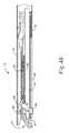
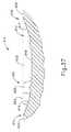
図1〜図7は、外科的処置を行うために、図1に描写されるような非関節動作状態で、トロカールカニューレを通って患者内の手術部位まで挿入するように寸法決めされている、例示の外科用ステープル留め及び切断器具(10)を示している。単なる例示として、患者の腹部内に、患者の2本の肋骨の間に、又はその他の部位に、かかるトロカールを挿入してもよい。一部の状況では、器具(10)は、トロカールなしで使用される。例えば、開胸又は他の種類の切開によって、器具(10)を直接挿入してもよい。本発明の例の器具(10)は、シャフト(22)に結合しているハンドル部分(20)を含む。シャフト(22)は、関節動作ジョイント(11)内で遠位方向に終端し、関節動作ジョイント(11)は、エンドエフェクタ(12)と更に連結されている。本明細書では、「近位」及び「遠位」といった用語は、器具(10)のハンドル部分(20)を握っている臨床医を基準として使用されていることを理解されたい。したがって、エンドエフェクタ(12)は、より近位にあるハンドル部分(20)に対して遠位である。便宜上、また説明を明確にするため、本明細書では「垂直」及び「水平」といった空間的な用語を図面に対して使用する点も更に認識されるであろう。しかしながら、外科用器具は、多くの配向及び姿勢で使用され、これらの用語は、制限的かつ絶対的でないことが意図されている。I. Exemplary Surgical Stapler FIGS. 1-7 are sized to be inserted through a trocar cannula to a surgical site within a patient in a non-articulated state as depicted in FIG. 1 for performing a surgical procedure. Fig. 2 shows an exemplary surgical stapling and cutting instrument (10) as determined. By way of example only, such a trocar may be inserted into the patient's abdomen, between the patient's two ribs, or elsewhere. In some situations, the instrument (10) is used without a trocar. For example, the instrument (10) may be inserted directly by thoracotomy or other type of incision. The example instrument (10) of the present invention includes a handle portion (20) coupled to a shaft (22). The shaft (22) terminates distally within the articulating joint (11), and the articulating joint (11) is further coupled to an end effector (12). It should be understood that the terms “proximal” and “distal” are used herein with reference to a clinician holding the handle portion (20) of the instrument (10). Thus, the end effector (12) is distal to the more proximal handle portion (20). It will further be appreciated that, for convenience and clarity of explanation, spatial terms such as “vertical” and “horizontal” are used herein for the drawings. However, surgical instruments are used in many orientations and postures, and these terms are intended to be limiting and not absolute.
一部の形態においては、シャフト(22)は、本件と同日に出願され、その開示が参照により本明細書に組み込まれている、「Surgical Instrument with Multi−Diameter Shaft」と題される米国特許出願第号[代理人整理番号END7181USNP.0599180]の少なくとも一部の教示に従って構築される。シャフト(22)の他の好適な構成は、本明細書の教示を鑑みれば当業者には明らかになるであろう。 In some forms, the shaft (22) is filed on the same date as the present application, and is a US patent application entitled “Surgical Instrument with Multi-Diameter Shaft”, the disclosure of which is incorporated herein by reference. No. [Attorney Docket Number END7181USNP. 0599180] at least in part. Other suitable configurations for the shaft (22) will be apparent to those skilled in the art in view of the teachings herein.
関節動作ジョイント(11)及びエンドエフェクタ(12)が、トロカールのカニューレ通路を通って一旦挿入されると、関節動作ジョイント(11)は、図1に幻影で描写されるように、関節動作制御部(13)によって遠隔に操作され、関節動作することができ、エンドエフェクタ(12)を、シャフト(22)の長手方向軸線(LA)から所望の角度(α)に偏向することができる。エンドエフェクタ(12)は、そのようにして、所望の角度から又は他の理由のために、臓器の背後に到達する又は組織に近付くことができる。一部の形態においては、関節動作ジョイント(11)は、単一の平面に沿ってエンドエフェクタ(12)を偏向することができる。その他の形態においては、関節動作ジョイント(11)は、2つ以上の平面に沿ってエンドエフェクタを偏向することができる。関節動作ジョイント(11)及び関節動作制御部(13)は、本明細書で引用される多数の引用文献のうちのいずれかの教示に従って構成されてもよい。あるいは、関節動作ジョイント(11)及び/又は関節動作制御部(13)は、他の任意の好適な構成を有していてもよい。単なる例示として、関節動作制御部(13)は、シャフト(22)の長手方向軸線(LA)に直交する軸を中心に回転するノブとして代わりに構成されてもよい。 Once the articulation joint (11) and the end effector (12) are inserted through the trocar cannula passage, the articulation joint (11) is articulated, as depicted in phantom in FIG. It can be remotely operated and articulated by (13), and the end effector (12) can be deflected from the longitudinal axis (LA) of the shaft (22) to a desired angle (α). The end effector (12) can thus reach behind the organ or approach the tissue from the desired angle or for other reasons. In some forms, the articulating joint (11) can deflect the end effector (12) along a single plane. In other configurations, the articulating joint (11) can deflect the end effector along more than one plane. The articulation joint (11) and the articulation controller (13) may be configured in accordance with the teachings of any of a number of cited references cited herein. Alternatively, the joint motion joint (11) and / or the joint motion control unit (13) may have any other suitable configuration. Merely by way of example, the joint motion controller (13) may alternatively be configured as a knob that rotates about an axis that is orthogonal to the longitudinal axis (LA) of the shaft (22).
一部の形態においては、関節動作ジョイント(11)及び/又は関節動作制御部(13)は、本件と同日に出願され、その開示が参照により本明細書に組み込まれている、「Surgical Instrument End Effector Articulation Drive with Pinion and Opposing Racks」と題される米国特許出願第号[代理人整理番号END7174USNP.0599176]の少なくとも一部の教示に従って、構築され、動作可能である。関節動作ジョイント(11)はまた、その開示が参照により本明細書に組み込まれている、米国特許出願第号[代理人整理番号END7181USNP.0599180]の少なくとも一部の教示に従って、構築され、動作可能である。関節動作ジョイント(11)及び関節動作制御部(13)が取り得る他の好適な形態は、本明細書の教示を鑑みれば当業者には明らかになるであろう。 In some forms, the articulation joint (11) and / or the articulation control (13) is filed on the same day as the present application, the disclosure of which is incorporated herein by reference, “Surgical Instrument End. US Patent Application No. [Attorney Docket No. END7174USNP., Entitled “Effects Articulation Drive with Pinion and Opposing Racks”. 0599176] is constructed and operable. The articulating joint (11) is also disclosed in US Patent Application No. [Attorney Docket No. END7181USNP., The disclosure of which is incorporated herein by reference. 0599180] is constructed and operable. Other suitable forms that the articulation joint (11) and articulation control (13) may take will be apparent to those skilled in the art in view of the teachings herein.
本発明の例のエンドエフェクタ(12)は、下部つかみ具(16)及び枢動可能アンビル(18)を含む。一部の形態においては、下部つかみ具(16)は、本件と同日に出願され、その開示が参照により本明細書に組み込まれている、「Installation Features for Surgical Instrument End Effector Cartridge」と題される米国特許出願第号[代理人整理番号END7182USNP.0599227]の少なくとも一部の教示に従って構築される。アンビル(18)は、本件と同日に出願され、その開示が参照により本明細書に組み込まれている、「Integrated Tissue Positioning and Jaw Alignment Features for Surgical Stapler」と題される米国特許出願第号[代理人整理番号END7176USNP.0599177]の少なくとも一部の教示、本件と同日に出願され、その開示が参照により本明細書に組み込まれている、「Jaw Closure Feature for End Effector of Surgical Instrument」と題される米国特許出願第号[代理人整理番号END7177USNP.0599225]の少なくとも一部の教示、及び/又は以下の教示の少なくとも一部に従って構築することができる。下部つかみ具(16)及びアンビル(18)が取り得る他の好適な形態は、本明細書の教示を鑑みれば当業者には明らかになるであろう。 The example end effector (12) of the present invention includes a lower grip (16) and a pivotable anvil (18). In some forms, the lower grip (16) is entitled "Instrumentation Features for Surgical Instrument End Effector Cartridge", filed on the same day as this application, the disclosure of which is incorporated herein by reference. US Patent Application No. [Attorney Docket No. END7182USNP. [0599227]. Anvil (18) was filed on the same date as this case and is incorporated herein by reference, the US patent application number entitled “Integrated Tissue Positioning and Jaw Alignment Features for Surgical Stapler” [proxy. Person reference number END7176USNP. No. 0599177], US Patent Application No. “Jaw Closer Feature for End Effector Surgical Instrument,” filed on the same day as this application, the disclosure of which is incorporated herein by reference. [Agent reference number END7177USNP. 0599225] and / or in accordance with at least some of the following teachings. Other suitable forms that the lower gripper (16) and anvil (18) may take will be apparent to those skilled in the art in view of the teachings herein.
ハンドル部分(20)は、ピストル把持部(24)及び閉鎖トリガー(26)を含む。閉鎖トリガー(26)は、ピストル把持部(24)に向かって枢動可能であり、エンドエフェクタ(12)の下部つかみ具(16)に向かってアンビル(18)のクランプ又は閉鎖を行うことができる。かかるアンビル(18)の閉鎖は、閉鎖管(32)及び閉鎖用リング(33)を介してもたらされ、その両方とも、ピストル把持部(24)に対する閉鎖トリガー(26)の枢動に応じてハンドル部分(20)に対して長手方向に移動する。閉鎖管(32)は、シャフト(22)の長さに沿って延在し、閉鎖用リング(33)は、関節動作ジョイント(11)より遠位に位置付けられる。関節動作ジョイント(11)は、閉鎖管(32)から閉鎖用リング(33)までの長手方向の運動を伝達/伝動するように動作可能である。 The handle portion (20) includes a pistol grip (24) and a closure trigger (26). The closure trigger (26) is pivotable towards the pistol grip (24) and can clamp or close the anvil (18) towards the lower grip (16) of the end effector (12). . Such anvil (18) closure is effected via a closure tube (32) and a closure ring (33), both in response to pivoting of the closure trigger (26) relative to the pistol grip (24). Move longitudinally relative to the handle portion (20). The closure tube (32) extends along the length of the shaft (22) and the closure ring (33) is positioned distal to the articulating joint (11). The articulating joint (11) is operable to transmit / transmit longitudinal movement from the closing tube (32) to the closing ring (33).
ハンドル部分(20)はまた、発射トリガー(28)を含む。細長部材(136)(図11に図示)は、シャフト(22)を通って長手方向に延在し、発射トリガー(28)の作動に応じて、ハンドル部分(20)から発射ビーム(14)まで長手方向の発射動作を伝達する。以下で更に詳細に説明されるように、発射ビーム(14)が遠位に移動することにより、エンドエフェクタ(12)においてクランプされた組織のステープル留め及び切断が行われる。その後、トリガー(26、28)を解放し、エンドエフェクタ(12)から組織を解放することができる。 The handle portion (20) also includes a firing trigger (28). An elongate member (136) (shown in FIG. 11) extends longitudinally through the shaft (22) and from the handle portion (20) to the firing beam (14) in response to actuation of the firing trigger (28). Transmit longitudinal firing motion. As described in more detail below, the firing beam (14) moves distally to staple and cut the clamped tissue at the end effector (12). The trigger (26, 28) can then be released and the tissue can be released from the end effector (12).
図3〜図6は、数多くの機能を実行するためにEビーム形態の発射ビーム(14)を取り入れているエンドエフェクタ(12)を示す。Eビーム形態は、単なる例示としての一例であることを理解されたい。発射ビーム(14)は、他の好適な形態を有していてもよく、非Eビーム形態も含まれるが、これに限定されるものではない。図4A及び図4Bに最もわかりやすく示されるように、発射ビーム(14)は、横断方向に配向された上方ピン(38)と、発射ビームキャップ(44)と、横断方向に配向された中間ピン(46)と、遠位方向に提示された切断縁部(48)と、を含む。上方ピン(38)は、アンビル(18)の長手方向アンビルスロット(42)内に位置付けられ、長手方向アンビルスロット(42)内を移動可能である。発射ビームキャップ(44)は、下部つかみ具(16)を通って形成された下部つかみ具スロット(45)(図4Bに図示)を通って延在する発射ビーム(14)を有することによって、下部つかみ具(16)の下側表面に摺動可能に係合する。中間ピン(46)は、発射ビームキャップ(44)と協働する下部つかみ具(16)の上面に摺動可能に係合する。これにより、発射ビーム(14)は、発射中に、エンドエフェクタ(12)の間隔を肯定的に取る。 3-6 show an end effector (12) that incorporates a firing beam (14) in the form of an E-beam to perform a number of functions. It should be understood that the E-beam configuration is merely an example. The firing beam (14) may have other suitable forms, including but not limited to non-E beam forms. As best shown in FIGS. 4A and 4B, the firing beam (14) comprises a transversely oriented upper pin (38), a firing beam cap (44), and a transversely oriented intermediate pin. (46) and a cutting edge (48) presented in the distal direction. The upper pin (38) is positioned within the longitudinal anvil slot (42) of the anvil (18) and is movable within the longitudinal anvil slot (42). The firing beam cap (44) has a firing beam (14) extending through a lower gripper slot (45) (shown in FIG. 4B) formed through the lower gripper (16) so that A slidably engaged lower surface of the gripper (16). The intermediate pin (46) slidably engages the upper surface of the lower grip (16) cooperating with the firing beam cap (44). This causes the firing beam (14) to positively space the end effector (12) during firing.
一部の非Eビーム形態の発射ビーム(14)は、上方ピン(38)、中間ピン(46)、及び/又は発射ビームキャップ(44)が欠けていてもよい。器具(10)のかかる形態のいくつかは、閉鎖用リング(33)又はその他の機構に単に依存し、発射ビーム(14)が遠位位置へと前進する間、閉鎖位置までアンビル(18)を枢動させ、閉鎖位置でアンビル(18)を留めておいてもよい。単なる例示として、発射ビーム(14)及び/又は関連するロックアウト機構は、本件と同日に出願され、その開示が参照により本明細書に組み込まれている、「Lockout Feature for Movable Cutting Member of Surgical Instrument」と題される米国特許出願第 号[代理人整理番号END7175USNP.0599231]の少なくとも一部の教示に従って、構築され、動作可能である。発射ビーム(14)が取り得る他の好適な形態は、本明細書の教示を鑑みれば当業者には明らかになるであろう。 Some non-E beam form firing beams (14) may lack an upper pin (38), an intermediate pin (46), and / or a firing beam cap (44). Some such forms of the instrument (10) simply rely on a closure ring (33) or other mechanism to move the anvil (18) to the closed position while the firing beam (14) is advanced to the distal position. It may be pivoted to keep the anvil (18) in the closed position. By way of example only, a launch beam (14) and / or associated lockout mechanism is filed on the same day as the present application, the disclosure of which is incorporated herein by reference, “Lockout Feature for Mobile Cutting Member of Instrumental Instrument”. US Patent Application No. [Attorney Docket No. END7175USNP. 0599231] is constructed and operable. Other suitable forms that the firing beam (14) may take will be apparent to those skilled in the art in view of the teachings herein.
図3は、近位に位置付けられている本発明の例の発射ビーム(14)と、開放位置まで枢動され、下部つかみ具(16)のチャネル内に、未使用のステープルカートリッジ(37)を着脱可能に装着できるようにするアンビル(18)と、を示す。図5及び図6に最もわかりやすく示されるように、この例のステープルカートリッジ(37)は、上部デッキ(72)を提示し、下部カートリッジトレー(74)と連結されている、カートリッジ本体(70)を含む。図3に最もわかりやすく示されるように、垂直スロット(49)は、ステープルカートリッジ(37)の一部を通って形成されている。図3にまた最もわかりやすく示されるように、3列のステープル開口部(51)は、垂直スロット(49)の片側の上部デッキ(72)を通って形成され、垂直スロット(49)の他方の側の上部デッキ(72)を通って、他の1組の3列のステープル開口部(51)が形成される。勿論、任意の他の好適なステープルの列数(例えば、2列、4列、その他の列数)が提供されてもよい。再度、図4A〜図6を参照すると、楔形スレッド(41)及び複数のステープルドライバ(43)は、カートリッジ本体(70)とトレー(74)との間に捕捉されており、楔形スレッド(41)は、ステープルドライバ(43)よりも近位に位置する。楔形スレッド(41)は、ステープルカートリッジ(37)内を長手方向に可動であり、一方、ステープルドライバ(43)は、ステープルカートリッジ(37)内を垂直方向に可動である。ステープル(47)もまた、カートリッジ本体(70)内に、対応するステープルドライバ(43)の上に位置付けられる。特に、それぞれのステープル(47)は、ステープルドライバ(43)によってカートリッジ本体(70)内を垂直方向に駆動され、関連するステープル開口部(51)を通ってステープル(47)を外へと駆動する。図4A、図4B、及び図6に最もわかりやすく示されるように、楔形スレッド(41)は、楔形スレッド(41)がステープルカートリッジ(37)を通って遠位方向に駆動されるにつれてステープルドライバ(43)を上方に促す、傾斜したカム表面を提示する。 FIG. 3 shows an example firing beam (14) positioned proximally and an unused staple cartridge (37) pivoted to the open position and into the channel of the lower grip (16). An anvil (18) is shown that allows it to be detachably mounted. As best shown in FIGS. 5 and 6, the staple cartridge (37) of this example presents an upper deck (72) and is connected to a lower cartridge tray (74), the cartridge body (70). including. As best seen in FIG. 3, the vertical slot (49) is formed through a portion of the staple cartridge (37). As also best seen in FIG. 3, three rows of staple openings (51) are formed through the upper deck (72) on one side of the vertical slot (49) and the other of the vertical slots (49). Through the upper deck (72) on the side, another set of three rows of staple openings (51) is formed. Of course, any other suitable number of staple rows (eg, two, four, other numbers of rows) may be provided. Referring again to FIGS. 4A-6, the wedge-shaped thread (41) and the plurality of staple drivers (43) are captured between the cartridge body (70) and the tray (74), and the wedge-shaped thread (41). Is located more proximal than the staple driver (43). The wedge thread (41) is movable longitudinally within the staple cartridge (37), while the staple driver (43) is movable vertically within the staple cartridge (37). Staples (47) are also positioned in the cartridge body (70) over corresponding staple drivers (43). In particular, each staple (47) is driven vertically in the cartridge body (70) by a staple driver (43) and drives the staple (47) out through the associated staple opening (51). . As best shown in FIGS. 4A, 4B, and 6, the wedge-shaped thread (41) is a staple driver (as the wedge-shaped thread (41) is driven distally through the staple cartridge (37)). 43) presents an inclined cam surface that urges upward.
一部の形態においては、ステープルカートリッジ(37)は、その開示が参照により本明細書に組み込まれている、米国特許出願第号[代理人整理番号END7176USNP.0599177]の少なくとも一部の教示に従って、構築され、動作可能である。追加的にあるいは代替的に、ステープルカートリッジ(37)は、その開示が参照により本明細書に組み込まれている、米国特許出願第号[代理人整理番号END7182USNP.0599227]の少なくとも一部の教示に従って、構築され、動作可能である。ステープルカートリッジ(37)が取り得る他の好適な形態は、本明細書の教示を鑑みれば当業者には明らかになるであろう。 In some forms, the staple cartridge (37) is a U.S. Patent Application No. [Attorney Docket No. END7176USNP. 0599177] is constructed and operable. Additionally or alternatively, staple cartridge (37) is disclosed in U.S. Patent Application No. [Attorney Docket No. END7182USNP. 0599227] is constructed and operable. Other suitable forms that the staple cartridge (37) may take will be apparent to those skilled in the art in view of the teachings herein.
図4A及び図4Bに描写されるように、閉鎖管(32)及び閉鎖用リング(33)を遠位方向に前進させることによってエンドエフェクタ(12)が閉鎖された状態で、発射ビーム(14)は、次いで、上方ピン(38)を長手方向アンビルスロット(42)に入れることによって、アンビル(18)と係合して前進する。プッシャブロック(80)(図5に図示)は、発射ビーム(14)の遠位端に位置し、かつ、発射トリガー(28)が作動した際、発射ビーム(14)がステープルカートリッジ(37)を通って遠位方向に前進するにつれてプッシャブロック(80)が楔形スレッド(41)を遠位方向に押すように、楔形スレッド(41)と係合するように構成されている。かかる発射中に、発射ビーム(14)の切断縁部(48)は、ステープルカートリッジ(37)の垂直スロット(49)に入り、ステープルカートリッジ(37)とアンビル(18)との間にクランプされている組織を切断する。図4A及び図4Bに示すように、中間ピン(46)及びプッシャブロック(80)は共に、ステープルカートリッジ(37)内の垂直スロット(49)内に入ることによって、ステープルカートリッジ(37)を作動させ、楔形スレッド(41)をステープルドライバ(43)との上向きのカム接触へと駆動すると、ステープル(47)は、ステープル開口部(51)を通って外へと駆動され、アンビル(18)の内面のステープル成形ポケット(53)(図3に図示)との成形接触へと駆動される。図4Bは、組織の切断及びステープル留めが完了した後、遠位方向に完全に移動した発射ビーム(14)を示す。ステープル成形ポケット(53)は、図4A及び図4Bの図から意図的に省略されているが、図3に図示されていることを理解されたい。また、アンビル(18)は、図5の図から意図的に省略されていることも理解されたい。 As depicted in FIGS. 4A and 4B, the firing beam (14) with the end effector (12) closed by advancing the closure tube (32) and the closure ring (33) in the distal direction. Is then advanced into engagement with the anvil (18) by placing the upper pin (38) into the longitudinal anvil slot (42). The pusher block (80) (shown in FIG. 5) is located at the distal end of the firing beam (14), and when the firing trigger (28) is activated, the firing beam (14) pushes the staple cartridge (37). The pusher block (80) is configured to engage the wedge-shaped thread (41) so as to push the wedge-shaped thread (41) distally as it advances distally therethrough. During such firing, the cutting edge (48) of the firing beam (14) enters the vertical slot (49) of the staple cartridge (37) and is clamped between the staple cartridge (37) and the anvil (18). Cut the tissue. As shown in FIGS. 4A and 4B, both the intermediate pin (46) and the pusher block (80) actuate the staple cartridge (37) by entering a vertical slot (49) in the staple cartridge (37). When the wedge-shaped thread (41) is driven into upward cam contact with the staple driver (43), the staple (47) is driven out through the staple opening (51) and the inner surface of the anvil (18). Is driven into forming contact with the staple forming pocket (53) (shown in FIG. 3). FIG. 4B shows the firing beam (14) fully moved in the distal direction after tissue cutting and stapling is complete. It should be understood that the staple forming pocket (53) is intentionally omitted from the views of FIGS. 4A and 4B, but is illustrated in FIG. It should also be understood that the anvil (18) is intentionally omitted from the view of FIG.
図7は、組織(90)を貫通する1回のストロークを介して作動しているエンドエフェクタ(12)を示す。図示されるように、切断縁部(48)(図7では不明瞭)は、組織(90)を切断しており、一方、ステープルドライバ(43)は、切断縁部(48)が作り出した切断線の各側で、組織(90)を通ってステープル(47)の3本の交互の列を駆動している。この例では、全てのステープル(47)が切断線とほぼ平行に配向されているが、ステープル(47)は、任意の好適な配向で位置付けられてもよいことを理解されたい。本発明の例では、第1のストロークが完了した後にエンドエフェクタ(12)をトロカールから後退させ、使用済みのステープルカートリッジ(37)を新しいステープルカートリッジと交換し、その後に、エンドエフェクタ(12)を再びトロカールを通って挿入して、ステープル留めする部位に到達し、更なる切断及びステープル留めを行う。所望の量の切断及びステープル(47)が提供されるまで、このプロセスを繰り返すことができる。トロカールを通って挿入及び後退を可能にするためにアンビル(18)を閉鎖する必要があり得、ステープルカートリッジ(37)の交換を可能にするためにアンビル(18)を開放する必要があり得る。 FIG. 7 shows end effector (12) operating through a single stroke through tissue (90). As shown, the cutting edge (48) (unclear in FIG. 7) is cutting tissue (90), while the staple driver (43) is the cutting created by cutting edge (48). On each side of the line, three alternating rows of staples (47) are driven through tissue (90). In this example, all staples (47) are oriented substantially parallel to the cutting line, but it should be understood that staples (47) may be positioned in any suitable orientation. In the present example, the end effector (12) is retracted from the trocar after the first stroke is completed, the used staple cartridge (37) is replaced with a new staple cartridge, and then the end effector (12) is replaced. Insert again through the trocar to reach the stapling site for further cutting and stapling. This process can be repeated until the desired amount of cut and staple (47) is provided. The anvil (18) may need to be closed to allow insertion and retraction through the trocar, and the anvil (18) may need to be opened to allow replacement of the staple cartridge (37).
各作動ストローク中に、ステープル(47)が組織を通って駆動されるのとほぼ同時に、切断縁部(48)が組織を切断することができることを理解されたい。本発明の例では、切断縁部(48)は、ステープル(47)の駆動にごくわずかに遅れて進むので、ステープル(47)は、切断縁部(48)が組織の同じ領域を通過する直前に組織を通って駆動されるが、この順序を逆にすることができること、又は、切断縁部(48)が、隣接するステープルと直接同期されてもよいことを理解されたい。図7は、2層(92、94)の組織(90)で作動しているエンドエフェクタ(12)を示しているが、エンドエフェクタ(12)は、単層の組織(90)を通って作動してもよく、又は2層(92、94)以上の組織を通って作動してもよいことを理解されたい。また、切断縁部(48)が作り出した切断線に隣接するステープル(47)の成形及び位置決めにより、切断線で組織を実質的に封着することができ、したがってその切断線での出血及び/又は他の体液の漏出を低減又は防止することができることも理解されたい。また、図7は、ほぼ扁平で、付着された平面な2層(92、94)の組織で作動しているエンドエフェクタ(12)を示しているが、エンドエフェクタ(12)は、血管、胃腸管の一部分などの筒状構造に交差して作動してもよいことを理解されたい。したがって、図7は、エンドエフェクタ(12)の企図される使用方法の制限について説明しているものとして考慮されるべきではない。器具(10)が使用され得る種々の好適な状況及び処置は、本明細書の教示を鑑みれば当業者には明らかになるであろう。 It should be understood that during each actuation stroke, the cutting edge (48) can cut the tissue at approximately the same time as the staple (47) is driven through the tissue. In the present example, the cutting edge (48) advances very slightly behind the drive of the staple (47) so that the staple (47) is just before the cutting edge (48) passes through the same region of tissue. It will be appreciated that this order can be reversed, or the cutting edge (48) may be directly synchronized with the adjacent staples. FIG. 7 shows the end effector (12) operating with two layers (92, 94) of tissue (90), but the end effector (12) operates through a single layer of tissue (90). It should be understood that it may or may operate through more than two layers (92, 94) of tissue. Also, the shaping and positioning of the staple (47) adjacent to the cutting line created by the cutting edge (48) can substantially seal the tissue at the cutting line, and thus bleeding and / or at the cutting line. It should also be understood that leakage of other bodily fluids can be reduced or prevented. FIG. 7 also shows the end effector (12) operating in a generally flat, attached, planar, two-layer (92, 94) tissue, where the end effector (12) is a blood vessel, gastrointestinal It should be understood that it may operate across a cylindrical structure, such as a portion of a tube. Accordingly, FIG. 7 should not be considered as describing the limitations of the intended use of the end effector (12). Various suitable situations and procedures in which the instrument (10) may be used will be apparent to those skilled in the art in view of the teachings herein.
器具(10)は、米国特許第4,805,823号、米国特許第5,415,334号、米国特許第5,465,895号、米国特許第5,597,107号、米国特許第5,632,432号、米国特許第5,673,840号、米国特許第5,704,534号、米国特許第5,814,055号、米国特許第6,978,921号、米国特許第7,000,818号、米国特許第7,143,923号、米国特許第7,303,108号、米国特許第7,367,485号、米国特許第7,380,695号、米国特許第7,380,696号、米国特許第7,404,508号、米国特許第7,434,715号、米国特許第7,721,930号、米国特許公開第2010/0264193号、及び/又は同第2012/0239012号のうちいずれかの教示に従って構成され、動作可能であることを理解されたい。上述のように、それらの特許及び公報のそれぞれの開示は、参照により本明細書に組み込まれている。器具(10)に提供することができる更なる例示の修正例は、以下により詳細に記載する。以下の教示が器具(10)に組み込むことができる種々の好適な方法は、当業者には明らかであろう。同様に、以下の教示を本明細書で引用される特許/公報の様々な教示と組み合わせることができる種々の好適な方法は、当業者には明らかであろう。また、以下の教示が、本明細書で引用される特許に教示された器具(10)又は装置に限定されないことも理解されたい。以下の教示は、外科用ステープラーとして分類されない器具を含む様々な他の種類の器具に容易に適用することができる。以下の教示を適用することができる種々の他の好適な装置及び状況は、本明細書の教示を鑑みれば当業者には明らかになるであろう。 The instrument (10) is described in U.S. Pat. No. 4,805,823, U.S. Pat. No. 5,415,334, U.S. Pat. No. 5,465,895, U.S. Pat. No. 5,597,107, U.S. Pat. 632,432, US Pat. No. 5,673,840, US Pat. No. 5,704,534, US Pat. No. 5,814,055, US Pat. No. 6,978,921, US Pat. , 000,818, U.S. Patent No. 7,143,923, U.S. Patent No. 7,303,108, U.S. Patent No. 7,367,485, U.S. Patent No. 7,380,695, U.S. Patent No. 7 , 380,696, U.S. Patent No. 7,404,508, U.S. Patent No. 7,434,715, U.S. Patent No. 7,721,930, U.S. Patent Publication No. 2010/0264193, and / or 2012/0239 Configured in accordance with any of the teachings of No. 12, it should be understood that it is operational. As mentioned above, the disclosures of each of those patents and publications are incorporated herein by reference. Further exemplary modifications that can be provided to the instrument (10) are described in more detail below. Various suitable ways in which the following teachings can be incorporated into the instrument (10) will be apparent to those skilled in the art. Similarly, various suitable ways in which the following teachings can be combined with the various teachings of the patents / publications cited herein will be apparent to those skilled in the art. It should also be understood that the following teachings are not limited to the instrument (10) or apparatus taught in the patents cited herein. The following teachings can be readily applied to various other types of instruments, including instruments that are not classified as surgical staplers. Various other suitable devices and situations to which the following teachings can be applied will be apparent to those skilled in the art in view of the teachings herein.
II.例示の電動駆動機構
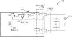
本発明の例では、器具(10)は、発射ビーム(14)の電動制御を提供する。図8〜図11は、発射ビーム(14)の電動制御を提供するために使用されてもよい、例示の構成要素を示す。特に、図8は、電池パック(104)(図1及び図2にも図示)からの電力を電動モーター(102)に供給するために使用されてもよい、例示の制御回路(100)を示す。以下で更に詳細に説明されるように、電動モーター(102)は、発射ビーム(14)を長手方向に移動させるように動作可能である。モーター(102)及び電池パック(104)を含む制御回路(100)全体を、ハンドル部分(20)内に収容することが可能であることを理解されたい。図8は、オープンスイッチとして発射トリガー(28)を示しているが、このスイッチは、発射トリガー(28)が作動しているときは閉じられていることを理解されたい。この例の回路(100)はまた、回路(100)を完了するために閉じられなければならない安全スイッチ(106)を含むが、安全スイッチ(106)は単なる任意選択的な構成要素であることを理解されたい。安全スイッチ(106)は、別装のボタン、スライダ、又はハンドル部分(20)の他の機構を作動することによって閉じることができる。II. Exemplary Electric Drive Mechanism In the example of the present invention, the instrument (10) provides electric control of the firing beam (14). 8-11 illustrate exemplary components that may be used to provide motorized control of the firing beam (14). In particular, FIG. 8 shows an exemplary control circuit (100) that may be used to supply power to the electric motor (102) from the battery pack (104) (also shown in FIGS. 1 and 2). . As described in more detail below, the electric motor (102) is operable to move the firing beam (14) longitudinally. It should be understood that the entire control circuit (100) including the motor (102) and battery pack (104) can be housed within the handle portion (20). Although FIG. 8 shows firing trigger (28) as an open switch, it should be understood that this switch is closed when firing trigger (28) is activated. The circuit (100) in this example also includes a safety switch (106) that must be closed to complete the circuit (100), although the safety switch (106) is merely an optional component. I want you to understand. The safety switch (106) can be closed by actuating a separate button, slider, or other mechanism of the handle portion (20).
本発明の例の回路(100)はまた、ロックアウトスイッチ(108)を含み、そのスイッチは、初期設定では閉じられているが、ロックアウト状態に応じて自動的に開くように構成されている。単なる例示として、ロックアウト状態は、下部つかみ具(16)にカートリッジ(37)がない状態、下部つかみ具(16)に使用済み(例えば、以前に発射された)カートリッジ(37)がある状態、アンビル(18)が十分に閉鎖されていない状態、器具(10)がすでに何度も発射されていると判断された状態、及び/又は任意の他の好適な状態のうち、1つ又は2つ以上の状態を含んでいてもよい。ロックアウト状態を検知するために使用されてもよい様々なセンサ、アルゴリズム、及び他の機構は、本明細書の教示を鑑みれば当業者には明らかになるであろう。同様に、本明細書の教示を鑑みれば、他の好適な種類のロックアウト状態も、当業者には明らかになるであろう。回路(100)が開いており、ロックアウトスイッチ(108)が開いている際は、モーター(102)は動作不可能であることを理解されたい。ロックアウト指示器(110)(例えば、LEDなど)は、ロックアウトスイッチ(108)の状態の視覚的指標を提供するように動作可能である。単なる例示として、ロックアウトスイッチ(108)、ロックアウト指示器(110)、及び関連する構成要素/機能性は、その開示が参照により本明細書に組み込まれている、2010年1月12日発行の「Electronic Lockouts and Surgical Instrument Including Same」と題される米国特許第7,644,848号の少なくとも一部の教示に従って構成することができる。 The example circuit (100) of the present invention also includes a lockout switch (108), which is closed by default but configured to open automatically in response to a lockout condition. . By way of example only, the lockout state may include a state where there is no cartridge (37) in the lower grip (16), a state where the lower grip (16) has a used (eg, previously fired) cartridge (37), One or two of: the anvil (18) is not sufficiently closed, the instrument (10) has been determined to have been fired many times, and / or any other suitable state The above states may be included. Various sensors, algorithms, and other mechanisms that may be used to detect a lockout condition will be apparent to those skilled in the art in view of the teachings herein. Similarly, other suitable types of lockout conditions will be apparent to those skilled in the art in view of the teachings herein. It should be understood that the motor (102) is inoperable when the circuit (100) is open and the lockout switch (108) is open. A lockout indicator (110) (eg, LED, etc.) is operable to provide a visual indication of the status of the lockout switch (108). By way of example only, a lockout switch (108), a lockout indicator (110), and associated components / functionality, issued January 12, 2010, the disclosure of which is incorporated herein by reference. In accordance with the teachings of at least part of US Patent No. 7,644,848 entitled "Electronic Lockouts and Surgical Instrument Inclusion Same".
一旦発射ビーム(14)が最遠位位置(例えば、切断ストロークの終わり)に到達すると、ストローク終了スイッチ(112)は自動的に閉鎖位置に切り替わり、モーター(102)に適用される電圧の極性を反転させる。これにより、モーター(102)の回転方向は反転するが、操作者は動作のこの段階で、発射トリガー(28)を解放しているだろう点が理解されるべきである。この動作状態において、電流は、逆方向指示器(114)(例えば、LEDなど)を通って流れ、モーター(102)の回転が反転したことを操作者に伝える視覚的指標を提供する。発射ビーム(14)が最遠位位置に到達した際、ストローク終了スイッチ(112)が自動的に閉鎖位置に切り替わる種々の好適な方法は、本明細書の教示を鑑みれば当業者には明らかになるであろう。同様に、逆方向指示器(114)が取り得る種々の好適な形態は、本明細書の教示を鑑みれば当業者には明らかになるであろう。 Once the firing beam (14) reaches the most distal position (eg, the end of the cutting stroke), the end of stroke switch (112) automatically switches to the closed position to change the polarity of the voltage applied to the motor (102). Invert. This should reverse the direction of rotation of the motor (102), but it should be understood that the operator would have released the firing trigger (28) at this stage of operation. In this operating state, current flows through the reverse indicator (114) (eg, LED, etc.) and provides a visual indication that informs the operator that the rotation of the motor (102) has been reversed. Various suitable ways in which the end-of-stroke switch (112) automatically switches to the closed position when the firing beam (14) reaches the most distal position will be apparent to those skilled in the art in view of the teachings herein. It will be. Similarly, various suitable forms that the reverse indicator (114) can take will be apparent to those skilled in the art in view of the teachings herein.
本発明の例のハンドル部分(20)はまた、手動戻りスイッチ(116)を含んでおり、そのスイッチは、回路(100)内にも図示されている。手動戻りスイッチ(116)は、「緊急救済(bailout)」機能として動作するように構成されており、操作者は、発射ストローク中、発射ビーム(14)の近位方向への縮退を即座に開始することができる。つまり、手動戻りスイッチ(116)は、発射ビーム(14)が部分的にしか遠位方向に前進していない場合、手動で作動できる。手動戻りスイッチ(116)は、ストローク終了スイッチ(112)と同様の機能性を提供し、モーター(102)に適用される電圧の極性を反転させ、それにより、モーター(102)の回転方向を反転させてもよい。この場合もまた、反転したことは、逆方向指示器(114)を通じて視覚的に表示される。 The example handle portion (20) of the present invention also includes a manual return switch (116), which is also shown in circuit (100). The manual return switch (116) is configured to operate as a “bailout” function, and the operator immediately begins to retract the firing beam (14) proximally during the firing stroke. can do. That is, the manual return switch (116) can be manually activated if the firing beam (14) is only partially advanced distally. The manual return switch (116) provides functionality similar to the stroke end switch (112), reversing the polarity of the voltage applied to the motor (102), thereby reversing the direction of rotation of the motor (102). You may let them. Again, the inversion is visually displayed through the reverse indicator (114).
一部の形態においては、1つ又は2つ以上のスイッチ(28、106、108、112、116)は、マイクロスイッチの形態をしている。他の好適な形態は、本明細書の教示を鑑みれば当業者には明らかになるであろう。前述に加えて又は前述の代わりに、少なくとも回路(100)の一部は、その開示が参照により本明細書に組み込まれている、2012年7月3日発行の「Motor−Driven Surgical Instrument」と題される米国特許第8,210,411号の少なくとも一部の教示に従って構成することができる。 In some forms, one or more switches (28, 106, 108, 112, 116) are in the form of microswitches. Other suitable forms will be apparent to those skilled in the art in view of the teachings herein. In addition to or in lieu of the foregoing, at least a portion of the circuit (100) is referred to as “Motor-Driven Surgical Instrument” issued July 3, 2012, the disclosure of which is incorporated herein by reference. It can be constructed according to the teachings of at least some of the entitled US Pat. No. 8,210,411.
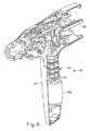
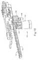
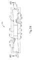
図9〜図11は、発射ビーム(14)の電動移動を提供するために使用されてもよい種々の機械的構成要素を示す。特に、図9は、ハンドル部分(20)のピストル把持部(24)に収容されたモーター(102)を示す。電池パック(104)(図1及び図2に図示)は、ピストル把持部(24)(例えば、モーター(102)の下)及び/又はハンドル部分(20)内の他の場所に位置していてもよいことを理解されたい。モーター(102)は、歯車組立体(122)と連結されている駆動軸(120)を有する。歯車組立体(122)は、外部筐体(図示せず)を有しており、図10に示すように、上部歯車(126)を駆動するように動作可能である。上部歯車(126)は、ハンドル部分(20)に固定されたピン(129)に回転可能に支持されているピニオン(128)に噛合する。それゆえに、モーター(102)の起動により、最終的にハンドル部分(20)内でピニオン(128)が回転することを理解されたい。 9-11 illustrate various mechanical components that may be used to provide motorized movement of the firing beam (14). In particular, FIG. 9 shows the motor (102) housed in the pistol grip (24) of the handle portion (20). The battery pack (104) (shown in FIGS. 1 and 2) is located elsewhere in the pistol grip (24) (eg, under the motor (102)) and / or the handle portion (20). I hope you understand. The motor (102) has a drive shaft (120) connected to the gear assembly (122). The gear assembly (122) has an outer housing (not shown) and is operable to drive the upper gear (126) as shown in FIG. The upper gear (126) meshes with a pinion (128) that is rotatably supported by a pin (129) fixed to the handle portion (20). Therefore, it should be understood that activation of the motor (102) will ultimately cause the pinion (128) to rotate within the handle portion (20).
図9及び図10にも示すように、移動ラック(130)は、ピニオン(128)に噛合する歯(132)を含み、ラック(130)は、ピニオン(128)が回転する際、長手方向に移動する。図11に示すように、ラック(130)は、細長部材(136)に連結されており、細長部材(136)は、シャフト(22)を通って延在し、発射ビーム(14)の近位端に連結する遠位端(138)を含む。細長部材(136)は、シャフト(22)内を移動し、細長部材(136)は、ラック(130)の長手方向動作を発射ビーム(14)に伝達する。それゆえに、モーター(102)の起動により、最終的に発射ビーム(14)がエンドエフェクタ(12)内を移動することを理解されたい。特に、モーター(102)は、発射ビーム(14)を遠位方向に駆動し、組織(90)を切断、かつ組織(90)内にステープル(47)を駆動させてもよい。スイッチ作動アーム(134)は、ラック(130)から横方向に延在し、かつ、発射ビーム(14)が最遠位位置(例えば、組織(90)が切断され、ステープル(47)が組織(90)内に駆動された後)に到達した際、ストローク終了スイッチ(112)に係合するように位置付けられている。上述のように、このストローク終了スイッチ(112)の係合により、モーター(102)は自動的に反転して、発射ビーム(14)を最遠位位置から近位位置へと戻し、それにより、アンビル(18)は、下部つかみ具(16)から離れるように枢動され、組織(90)を解放する。 As shown in FIGS. 9 and 10, the movable rack (130) includes teeth (132) that mesh with the pinion (128), and the rack (130) is longitudinally moved when the pinion (128) rotates. Moving. As shown in FIG. 11, the rack (130) is coupled to an elongated member (136) that extends through the shaft (22) and is proximal to the firing beam (14). A distal end (138) is coupled to the end. The elongate member (136) moves within the shaft (22), and the elongate member (136) transmits the longitudinal motion of the rack (130) to the firing beam (14). Therefore, it should be understood that activation of the motor (102) will ultimately cause the firing beam (14) to move within the end effector (12). In particular, the motor (102) may drive the firing beam (14) in a distal direction, cut the tissue (90), and drive the staples (47) into the tissue (90). The switch actuating arm (134) extends laterally from the rack (130), and the firing beam (14) is distally positioned (eg, tissue (90) is cut and staple (47) is tissue ( 90) after being driven into position, is positioned to engage the stroke end switch (112). As described above, engagement of this end-of-stroke switch (112) causes the motor (102) to automatically reverse, returning the firing beam (14) from the most distal position to the proximal position, thereby The anvil (18) is pivoted away from the lower jaw (16) to release the tissue (90).
「枢動する」という用語(及び「枢動」を基体とした類義語)の使用は、必ずしも固定軸を中心とした枢動運動を必要とすると理解されるべきではない。一部の形態においては、アンビル(18)は、アンビル(18)が下部つかみ具(16)に向かって動く際、細長スロット又はチャネルに沿ってスライドするピン(又は同様の機構)によって画定される軸を中心として枢動する。かかる形態においては、枢軸がスロット又はチャネルによって画定される経路に沿って移動する一方で、アンビル(18)も同時にその枢軸を中心として枢動する。追加的にあるいは代替的に、まず枢軸がスロット/チャネルに沿ってスライドし、次いで枢軸がスロット/チャネルに沿ってある一定の距離をスライドした後、アンビル(18)が枢軸を中心として枢動してもよい。かかるスライドする/移動するという枢動運動は、「枢動する(pivot、pivots)」、「枢動の(pivotal)」、「枢動可能な(pivotable)」、「枢動している(pivoting)」などの用語に包含されていることを理解されたい。勿論、一部の形態は、固定かつスロット又はチャネル内を移動しない軸を中心としたアンビル(18)の枢動運動を提供してもよい。 The use of the term “pivot” (and synonyms based on “pivot”) is not necessarily to be understood as requiring pivoting about a fixed axis. In some forms, the anvil (18) is defined by a pin (or similar mechanism) that slides along an elongated slot or channel as the anvil (18) moves toward the lower grip (16). Pivot about an axis. In such a configuration, the anvil (18) simultaneously pivots about its pivot while the pivot moves along a path defined by the slot or channel. Additionally or alternatively, the anvil (18) pivots about the pivot after the pivot first slides along the slot / channel and then the pivot slides a distance along the slot / channel. May be. Such sliding / moving pivotal movements are "pivot, pivots", "pivotal", "pivotable", "pivoting" It should be understood that terms such as ")" are encompassed. Of course, some configurations may provide a pivoting motion of the anvil (18) about an axis that is fixed and does not move in the slot or channel.
前述に加えて又は前述の代わりに、発射ビーム(14)を駆動するように動作可能な機構は、その開示が参照により本明細書に組み込まれている、米国特許公開第2012/0239012号の少なくとも一部の教示に従って、かつ/又はその開示もまた参照により本明細書に組み込まれている、米国特許公報第2012/0239012号の少なくとも一部の教示に従って、構成することができる。発射ビーム(14)の電動化を提供するための他の好適な構成要素、機構、及び構成は、本明細書の教示を鑑みれば当業者には明らかになるであろう。また、他の形態において、発射ビーム(14)のマニュアル駆動が提供され、モーターが省かれてもよいことも理解されたい。単なる例示として、発射ビーム(14)は、本明細書で引用されるその他の特許/特許公報の参照の少なくとも一部の教示に従って作動することができる。 In addition to or in lieu of the foregoing, a mechanism operable to drive the firing beam (14) is described in US Patent Publication No. 2012/0239012, the disclosure of which is incorporated herein by reference. In accordance with some teachings and / or in accordance with at least some teachings of US Patent Publication No. 2012/0239012, the disclosure of which is also incorporated herein by reference. Other suitable components, mechanisms, and configurations for providing motorization of the firing beam (14) will be apparent to those skilled in the art in view of the teachings herein. It should also be understood that in other configurations, manual drive of the firing beam (14) may be provided and the motor may be omitted. Merely by way of example, the firing beam (14) may operate according to the teachings of at least some of the other patent / patent publication references cited herein.
III.例示のアンビル構成
上述のように、楔形スレッド(41)が遠位方向に駆動される際、楔形スレッド(41)は、カム作用を提供し、ステープルドライバ(43)をステープルカートリッジ(37)内で上方へと駆動する。ステープルドライバ(43)が上方へと移動するこの動きにより、ステープル(47)は上方へと押され、ステープル開口部(51)を通って押し出される。これにより、各ステープル(47)は、アンビル(18)の関連するステープル成形ポケット(53)に押し込まれ、最終的に、曲がった/成形されたステープル(47)となる。ステープル(47)の脚部は、アンビル(18)に向かって駆動される際に組織の層(90、92)を貫通し、成形されたステープル(47)は、組織の層(90、92)を固定する(図7に図示)。III. Exemplary Anvil Configuration As described above, when the wedge-shaped thread (41) is driven in the distal direction, the wedge-shaped thread (41) provides camming and causes the staple driver (43) to move within the staple cartridge (37). Drive upward. This movement of the staple driver (43) moving upward causes the staple (47) to be pushed upward and pushed out through the staple opening (51). This causes each staple (47) to be pushed into the associated staple forming pocket (53) of the anvil (18), eventually resulting in a bent / shaped staple (47). The legs of the staple (47) penetrate the tissue layer (90, 92) when driven toward the anvil (18), and the formed staple (47) is the tissue layer (90, 92). Is fixed (shown in FIG. 7).
ステープル成形ポケット(53)の構成は、成形されたステープル(47)の構成に対して大きな影響を与えることがあり、ステープル成形ポケット(53)の構成の変化が、ステープル成形ポケット(53)によって成形されたステープル(47)の構成を大きく変え得ることを理解されたい。また、ステープル成形ポケット(53)によって成形されたステープル(47)の構成の変化により、成形されたステープル(47)と組織の層(90、92)との相互作用の方法に対して大きな影響を与え得ることが理解されるであろう。例えば、成形されたステープル(47)の構成の一部は、その他の成形されたステープル(47)の構成と比べ、組織の層(90、92)においてより優れた止血を提供できる。その他の単なる例示の一例として、成形されたステープル(47)の構成の一部は、その他の成形されたステープル(47)の構成と比べ、組織の層(90、92)の付着状態をよりよく固定できる。更に他の単なる例示の一例として、成形されたステープル(47)の構成の一部は、その他の成形されたステープル(47)の構成と比べ、組織の層(90、92)により多くの損傷を(例えば、より多くの組織を傷つけることによって)負わせることがあり、それによって、成形されたステープル(47)の止血を提供する能力かつ/又は層(90、92)の付着状態を固定する能力などに影響を及ぼすことがある。いくつかの例示のステープル成形ポケット(53)の構成は、以下で更に詳細に説明されるが、その他の構成についても、本明細書の教示を鑑みれば当業者には明らかになるであろう。 The configuration of the staple forming pocket (53) can greatly affect the configuration of the formed staple (47), and changes in the configuration of the staple forming pocket (53) are formed by the staple forming pocket (53). It should be understood that the configuration of the formed staple (47) can vary greatly. Also, the change in the configuration of the staple (47) formed by the staple forming pocket (53) has a great influence on the method of interaction between the formed staple (47) and the tissue layers (90, 92). It will be understood that it can be given. For example, some of the shaped staple (47) configurations can provide better hemostasis in the tissue layers (90, 92) compared to other shaped staple (47) configurations. As another merely illustrative example, some of the configurations of the shaped staple (47) may provide better adhesion of the tissue layers (90, 92) than other configurations of the shaped staple (47). Can be fixed. As yet another merely illustrative example, some of the shaped staple (47) configurations may cause more damage to the tissue layers (90, 92) than other shaped staple (47) configurations. Ability to inflict (eg, by damaging more tissue), thereby providing hemostasis of molded staples (47) and / or the ability to fix the adherence of layers (90, 92) May be affected. Some exemplary staple forming pocket (53) configurations are described in more detail below, but other configurations will be apparent to those skilled in the art in view of the teachings herein.
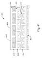
A.整列したチャネルを有する例示のステープル成形ポケット
図12及び図13は、上述のアンビル(18)の代わりに使用されてもよい、例示のアンビル(200)を示す。この例のアンビル(200)は、上述のアンビルスロット(42)に類似の、長手方向に延在するスロット(204)を画定する。発射ビーム(14)の上方部分は、器具(10)の切断/ステープル留めストローク中に、アンビルスロット(42)を通って移動する。アンビル(200)はまた、組織がアンビル(200)とステープルカートリッジ(37)の上部デッキ(72)との間でクランプされた際、組織に対して押圧する組織接触面(202)を含む。一連のステープル成形ポケット(210)は、組織接触面(202)に対して凹設されている。本発明の例では、アンビル(200)は、スロット(204)の各側に、2列(206、208)のステープル成形ポケット(210)を有している。しかしながら、スロット(204)の各側に、任意の他の好適な列数のステープル成形ポケット(210)が提供されてもよいことを理解されたい。単なる例示として、その他の形態において、スロット(204)の各側に3列のステープル成形ポケット(210)を含んでもよい。なお、スロット(204)の各側において、内列(206)は、外列(208)に対して長手方向にオフセットされる。このようにオフセットされた結果、図7に図示されている、成形されたステープル(47)が隣接する列の間で長手方向にオフセットされている状態と類似するだろう。勿論、ステープル成形ポケット(210)は、互いに任意の他の好適な配置関係を有していてもよい。A. Exemplary Staple Pocket with Aligned Channels FIGS. 12 and 13 show an exemplary anvil (200) that may be used in place of the anvil (18) described above. The example anvil (200) defines a longitudinally extending slot (204) similar to the anvil slot (42) described above. The upper portion of the firing beam (14) moves through the anvil slot (42) during the cutting / stapling stroke of the instrument (10). The anvil (200) also includes a tissue contacting surface (202) that presses against the tissue when the tissue is clamped between the anvil (200) and the upper deck (72) of the staple cartridge (37). The series of staple forming pockets (210) is recessed with respect to the tissue contacting surface (202). In the present example, the anvil (200) has two rows (206, 208) of staple forming pockets (210) on each side of the slot (204). However, it should be understood that any other suitable number of staple forming pockets (210) may be provided on each side of the slot (204). Merely by way of example, in other forms, three rows of staple forming pockets (210) may be included on each side of the slot (204). Note that on each side of the slot (204), the inner row (206) is offset in the longitudinal direction relative to the outer row (208). As a result of this offset, the shaped staple (47) illustrated in FIG. 7 will be similar to the longitudinal offset between adjacent rows. Of course, the staple forming pockets (210) may have any other suitable positional relationship to one another.
図14〜図16は、単一のステープル成形ポケット(210)をより詳細に示す。アンビル(200)のステープル成形ポケット(210)は全て、同様に構成されることを理解されたい。この例のステープル成形ポケット(210)は、第1のチャネル(220)及び第2のチャネル(240)を提供する。第2のチャネル(240)は、第1のチャネル(220)と整列する。区画壁面部(260)は、チャネル(220、240)の間を隔てている。チャネル(220、240)は、ステープル成形ポケット(210)に沿った壁部を通過し、かつステープル成形ポケット(210)に対して横断方向に延在する、垂直面に対して対称である。 14-16 show the single staple forming pocket (210) in more detail. It should be understood that all the staple forming pockets (210) of the anvil (200) are similarly configured. The staple forming pocket (210) of this example provides a first channel (220) and a second channel (240). The second channel (240) is aligned with the first channel (220). The partition wall surface portion (260) separates the channels (220, 240). The channels (220, 240) are symmetrical about a vertical plane that passes through the wall along the staple forming pocket (210) and extends transversely to the staple forming pocket (210).
チャネル(220)は、下向きに傾斜した凹状表面(concave surface)(222)によって長手方向に画定されており、その下向きに傾斜した凹状表面(222)は、区画壁面部(260)で終端する上向きに傾斜した凹状表面(224)へと平滑に移行する。チャネル(220)は、一対の側壁部(226、228)によって横方向に画定されており、その一対の側壁部(226、228)は、垂直方向に角度付けられ、側壁部(226、228)の下部領域は、側壁部(226、228)の上部領域よりも互いに近接している。側壁部(226、228)はまた、横方向に角度付けられ、区画壁面部(260)に隣接する側壁部(226、228)の端部は、区画壁面部(260)から更に離れている側壁部(226、228)の端部よりも互いに近接している。 The channel (220) is longitudinally defined by a downwardly inclined concave surface (222), the downwardly inclined concave surface (222) facing upwardly terminating at the partition wall (260). Smooth transition to a concave surface (224) inclined to The channel (220) is laterally defined by a pair of sidewalls (226, 228), the pair of sidewalls (226, 228) being angled in the vertical direction and the sidewalls (226, 228). These lower regions are closer to each other than the upper regions of the side wall portions (226, 228). The side walls (226, 228) are also laterally angled, and the end of the side wall (226, 228) adjacent to the partition wall (260) is further away from the partition wall (260). They are closer to each other than the ends of the parts (226, 228).
チャネル(240)は、下向きに傾斜した凹状表面(242)によって長手方向に画定されており、その下向きに傾斜した凹状表面(242)は、区画壁面部(260)で終端する上向きに傾斜した凹状表面(244)へと平滑に移行する。チャネル(240)は、一対の側壁部(246、248)によって横方向に画定されており、その一対の側壁部(246、248)は、垂直方向に角度付けられ、側壁部(246、248)の下部領域は、側壁部(246、248)の上部領域よりも互いに近接している。側壁部(246、248)はまた、横方向に角度付けられ、区画壁面部(260)に隣接する側壁部(246、248)の端部は、区画壁面部(260)から更に離れている側壁部(246、248)の端部よりも、互いに近接している。 The channel (240) is longitudinally defined by a downwardly inclined concave surface (242), the downwardly inclined concave surface (242) having an upwardly inclined concave shape terminating at a partition wall (260). Smooth transition to surface (244). The channel (240) is laterally defined by a pair of sidewalls (246, 248), the pair of sidewalls (246, 248) being angled in the vertical direction and the sidewalls (246, 248). These lower regions are closer to each other than the upper regions of the side wall portions (246, 248). The side walls (246, 248) are also laterally angled, and the end of the side wall (246, 248) adjacent to the partition wall (260) is further away from the partition wall (260). It is closer to each other than the ends of the parts (246, 248).
ステープル成形ポケット(210)はまた、ステープル成形ポケット(210)の長さに沿って延在する引込面(280、282)を含む。引込面(280)は、側壁部(226、246)及び区画壁面部(260)に隣接している。引込面(282)は、側壁部(228、248)及び区画壁面部(260)に隣接している。引込面(280、282)は、垂直方向に角度付けられ、ステープルがステープル成形ポケット(210)に向かって駆動される際、ステープルの脚部の先端をチャネル(220、240)へと導くように補助する。しかしながら、各引込面(280、282)と(組織接触面(202)が沿って位置している)水平面との間で画定される角度は、各側壁部(226、246、228、248)とその同じ水平面との間で画定される角度よりも小さい。引込面(280、282)はまた、ステープル成形の最終の段階の間、ステープル成形ポケット(210)において、非常に局部的な組織圧縮を容易にすることもできることを理解されたい。 Staple forming pocket (210) also includes retracting surfaces (280, 282) extending along the length of staple forming pocket (210). The drawing surface (280) is adjacent to the side wall portions (226, 246) and the partition wall surface portion (260). The drawing surface (282) is adjacent to the side wall portions (228, 248) and the partition wall surface portion (260). The lead-in surfaces (280, 282) are angled vertically to guide the staple leg tips into the channels (220, 240) as the staples are driven toward the staple forming pocket (210). Assist. However, the angle defined between each retracting surface (280, 282) and the horizontal plane (where the tissue contacting surface (202) is located) is different from each side wall (226, 246, 228, 248). Less than the angle defined between that same horizontal plane. It should be understood that the draw surface (280, 282) can also facilitate very localized tissue compression in the staple forming pocket (210) during the final stages of staple forming.
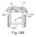
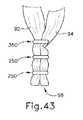
図17は、ステープル成形ポケット(210)によって成形され、2層(92、94)の組織を付着状態に固定している例示のステープル(250)を示す。ステープル(250)は、冠部(252)と、組織穿孔先端(272)を有する第1の脚部(270)と、組織穿孔先端(292)を有する第2の脚部(290)と、を含む。図示されるように、脚部(270、290)は互いに向かって曲げられ、先端(272、292)は、冠部(252)が沿って位置している平面を通過する。ステープル(250)の成形は、図18A〜図18Eで図示されている。先端(272、292)が、表面(222、242)に最初に接触する際、脚部(270、290)は、ほぼ真っ直ぐで、冠部(252)に対して垂直である。ステープル(250)がステープル成形ポケット(210)に向かって更に駆動され、各先端(272、292)がそれぞれのチャネル(220、240)の頂点(A1)に到達するポイントまで駆動されると、表面(222、242)は、互いに向かって方向を変えるように先端(272、292)を駆動させ、その結果、図18Bに示すように、脚部(270、290)は互いに向かって曲折する。ステープル(250)がステープル成形ポケット(210)に向かって更に駆動されると、図18Cに示すように、表面(224、244)は、冠部(252)に向かって方向を変えるように先端(272、292)を駆動させる。ステープル(250)がステープル成形ポケット(210)に向かって更に駆動されると、図18Dに示すように、表面(222、224、242、244)は、脚部(270、290)を変形し続け、先端(272、292)は、区画壁面部(260)を通り抜ける。一旦、ステープル(250)がステープル成形ポケット(210)内に完全に駆動されると、図18E及び図17に示すように、先端(272、292)は、冠部(252)を越える。したがって、先端(272、292)は、両方の組織の層(92、94)を2度貫通し、先端(272、292)は、冠部(252)と同じ側の層(92)を超えて位置付けられる。なお、この例では、成形されたステープル(250)は、「B」字状をなしている。また、この例では、ステープル(250)が成形された後、先端(272、292)は、冠部(252)と同じ外側に位置付けられる。場合によっては、先端(272、292)は、冠部(252)は超えないけれども、少なくとも層(94)を通過し、かつおそらく層(92)を2度通過する。FIG. 17 shows an exemplary staple (250) formed by staple forming pockets (210) securing two layers (92, 94) of tissue in an attached state. The staple (250) includes a crown (252), a first leg (270) having a tissue piercing tip (272), and a second leg (290) having a tissue piercing tip (292). Including. As shown, the legs (270, 290) are bent toward each other and the tips (272, 292) pass through the plane along which the crown (252) is located. The forming of the staple (250) is illustrated in FIGS. 18A-18E. When the tip (272, 292) first contacts the surface (222, 242), the legs (270, 290) are generally straight and perpendicular to the crown (252). When the staple (250) is driven further towards the staple forming pocket (210) and each tip (272, 292) is driven to the point where it reaches the apex (A1 ) of the respective channel (220, 240), The surfaces (222, 242) drive the tips (272, 292) to change direction toward each other, so that the legs (270, 290) bend toward each other as shown in FIG. 18B. As the staple (250) is driven further toward the staple forming pocket (210), the surface (224, 244) changes direction toward the crown (252) as shown in FIG. 18C. 272, 292) are driven. As the staple (250) is driven further toward the staple forming pocket (210), the surfaces (222, 224, 242, 244) continue to deform the legs (270, 290), as shown in FIG. 18D. The tips (272, 292) pass through the partition wall surface portion (260). Once the staple (250) is fully driven into the staple forming pocket (210), the tips (272, 292) extend over the crown (252), as shown in FIGS. 18E and 17. Thus, the tip (272, 292) penetrates both tissue layers (92, 94) twice and the tip (272, 292) extends beyond the layer (92) on the same side as the crown (252). Positioned. In this example, the formed staple (250) has a “B” shape. Also, in this example, after the staple (250) is formed, the tips (272, 292) are positioned on the same outside as the crown (252). In some cases, the tip (272, 292) does not exceed the crown (252), but passes at least through the layer (94) and possibly through the layer (92) twice.
なお、再度、図18Aを参照すると、ステープル成形ポケット(210)は、各脚部(270、290)の長手方向軸線と各対応するチャネル(220、240)の頂点(A1)を通過する平行軸との間の距離(d1)を提供する。更に、ステープル成形ポケット(210)は、冠部(252)の中心を通過する垂直軸と各チャネル(220、240)の頂点(A1)を通過する平行軸との間の距離(d2)を提供する。以下で更に詳細に説明されるように、いくつかの例においては、頂点(A1)を冠部(252)の中心を通過する垂直軸に向かって近付くように偏移させ、距離(d1)を長く、距離(d2)を短くすることが望ましい。いずれの場合も、いくつかの例においては、ポケット(210)の片側の距離(d1)は、ポケット(210)の他方の側の対応する距離(d1)よりも長いことが望ましいことを理解されたい。同様に、いくつかの例においては、ポケットの片側の距離(d2)は、ポケット(210)の他方の側の対応する距離(d2)よりも長いことが望ましいことを理解されたい。したがって、ポケットは、区画壁面部(260)を通過する垂直面に対して非対称であってもよいと考えられる。Referring again to FIG. 18A, the staple forming pocket (210) is parallel to the longitudinal axis of each leg (270, 290) and the vertex (A1 ) of each corresponding channel (220, 240). Provide the distance (d1 ) between the axes. Further, the staple forming pocket (210) has a distance (d2 ) between a vertical axis passing through the center of the crown (252) and a parallel axis passing through the apex (A1 ) of each channel (220, 240). I will provide a. As will be described in more detail below, in some examples, the apex (A1 ) is shifted toward the vertical axis passing through the center of the crown (252) and the distance (d1 ) Is long and the distance (d2 ) is short. In any case, in some examples, the distance of one side of the pocket (210) (d1) is that it is desirable longer than the distance (d1) corresponding on the other side of the pocket (210) I want you to understand. Similarly, it should be understood that in some examples, the distance (d2 ) on one side of the pocket is preferably longer than the corresponding distance (d2 ) on the other side of the pocket (210). Therefore, it is considered that the pocket may be asymmetric with respect to a vertical plane passing through the partition wall surface portion (260).
B.完全な斜壁によって隔てられたチャネルを有する例示のステープル成形ポケット
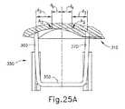
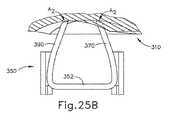
図19〜図21は、上述のアンビル(18)の代わりに使用されてもよい、例示のアンビル(300)を示す。この例のアンビル(300)は、上述のアンビルスロット(42)に類似の、長手方向に延在するスロット(304)を画定する。発射ビーム(14)の上方部分は、器具(10)の切断/ステープル留めストローク中に、アンビルスロット(42)を通って移動する。アンビル(300)はまた、組織がアンビル(300)とステープルカートリッジ(37)の上部デッキ(72)との間でクランプされた際、組織に対して押圧する組織接触面(302)を含む。一連のステープル成形ポケット(310)は、組織接触面(302)に対して凹設されている。本発明の例では、アンビル(300)は、スロット(304)の各側に、3列のステープル成形ポケット(310)を有している。しかしながら、スロット(304)の各側に、任意の他の好適な列数のステープル成形ポケット(310)が提供されてもよいことを理解されたい。単なる例示として、その他の形態において、スロット(304)の各側に2列又は3列以上のステープル成形ポケット(310)を含んでもよい。なお、スロット(304)の各側において、ステープル成形ポケット(310)の各列は、ステープル成形ポケット(310)の隣接する列に対して長手方向にオフセットされている。このようにオフセットされた結果、図7に図示されている、成形されたステープル(47)が隣接する列の間で長手方向にオフセットされている状態と類似する。勿論、ステープル成形ポケット(310)は、任意の他の好適な配置関係を有していてもよい。B. Exemplary Staple Forming Pocket with Channels Separated by Complete Slanted Walls FIGS. 19-21 show an exemplary anvil (300) that may be used in place of the anvil (18) described above. The example anvil (300) defines a longitudinally extending slot (304) similar to the anvil slot (42) described above. The upper portion of the firing beam (14) moves through the anvil slot (42) during the cutting / stapling stroke of the instrument (10). The anvil (300) also includes a tissue contacting surface (302) that presses against the tissue when the tissue is clamped between the anvil (300) and the upper deck (72) of the staple cartridge (37). The series of staple forming pockets (310) is recessed with respect to the tissue contacting surface (302). In the present example, the anvil (300) has three rows of staple forming pockets (310) on each side of the slot (304). However, it should be understood that any other suitable number of staple forming pockets (310) may be provided on each side of the slot (304). Merely by way of example, in other configurations, two or more rows of staple forming pockets (310) may be included on each side of the slot (304). It should be noted that on each side of the slot (304), each row of staple forming pockets (310) is offset in the longitudinal direction relative to an adjacent row of staple forming pockets (310). As a result of this offset, the molded staples (47) illustrated in FIG. 7 are similar to the longitudinal offset between adjacent rows. Of course, the staple forming pocket (310) may have any other suitable arrangement.
図22及び図23は、ステープル成形ポケット(310)をより詳細に示す。アンビル(300)のステープル成形ポケット(310)は全て、同様に構成されることを理解されたい。この例のステープル成形ポケット(310)は、第1のチャネル(320)及び第2のチャネル(340)を提供する。チャネル(320、340)は、概ね互いに平行であるが、この例においては、チャネル(320、340)は、互いに整列していない。区画壁部(360)は、チャネル(320、340)を隔てている。壁部(360)は、アンビル(300)のスロット(304)に対して斜めに配向されている。この例において、チャネル(320、340)は非対称であるが、チャネル(340)の構成とチャネル(320)の構成との間に実質的類似性は存在する。 22 and 23 show the staple forming pocket (310) in more detail. It should be understood that all the staple forming pockets (310) of the anvil (300) are similarly configured. The staple forming pocket (310) of this example provides a first channel (320) and a second channel (340). The channels (320, 340) are generally parallel to each other, but in this example the channels (320, 340) are not aligned with each other. A partition wall (360) separates the channels (320, 340). The wall (360) is oriented obliquely relative to the slot (304) of the anvil (300). In this example, the channels (320, 340) are asymmetric, but there is a substantial similarity between the configuration of the channel (340) and the configuration of the channel (320).
チャネル(320)は、下向きに傾斜した凹状表面(322)によって長手方向に画定されており、その下向きに傾斜した凹状表面(322)は、チャネル(320)の末端部(321)の組織接触面(302)で終端する上向きに傾斜した凹状表面(324)へと平滑に移行する。場合によっては、表面(322)は、単一の半径によって画定される。その他の場合によっては、表面(322)は、2つ以上の半径によって画定される。追加的にあるいは代替的に、表面(322)は、1つ又は2つ以上の半径と、垂直、水平、又はその他の角度に角度付けられた1つ又は2つ以上の扁平面と、によって画定される、1つ又は2つ以上の表面の組み合わせを含んでもよい。 The channel (320) is longitudinally defined by a downwardly inclined concave surface (322), which downwardly inclined concave surface (322) is the tissue contacting surface of the distal end (321) of the channel (320). Smooth transition to an upwardly inclined concave surface (324) terminating at (302). In some cases, surface (322) is defined by a single radius. In other cases, the surface (322) is defined by more than one radius. Additionally or alternatively, the surface (322) is defined by one or more radii and one or more flat surfaces angled at a vertical, horizontal, or other angle. May include one or a combination of two or more surfaces.
チャネル(320)は、第1の側壁部(323)、第2の側壁部、(325)、及び第3の側壁部(326)によって、片側に横方向に画定される。チャネル(320)は、第4の側壁部(328)によって、他方の側に横方向に画定される。チャネル(320)を画定するために、任意のその他の好適な数の側壁部が使用されてもよいことを理解されたい。本発明の例では、第1の側壁部(323)は、第4の側壁部(328)と概ね平行であるが、その他の好適な相関性が提供されてもよいことを理解されたい。第2の側壁部(325)は、第4の側壁部(328)に対して、第1の斜角を画定する。第3の側壁部(326)は、第4の側壁部(328)に対して、第2の斜角を画定する。第1の斜角は、第2の斜角よりも大きい。したがって、チャネル(320)の長さに対する幅を見た場合、チャネル(320)は、ステープルの脚部の入口端部(319)において、かつ第1の側壁部(323)と第4の側壁部(328)との間に画定される短い長さに沿って、最大の幅となる。チャネル(320)の幅は、その後、第2の側壁部(325)と第4の側壁部(328)との間に画定される長さの部分に沿って大幅に狭くなる。チャネル(320)の幅は、第3の側壁部(326)と第4の側壁部(328)との間に画定される長さの部分に沿って狭くなり続ける(が、大幅には狭くならない)。チャネル(320)は、末端部(321)において最小の幅となる。 The channel (320) is laterally defined on one side by a first sidewall (323), a second sidewall (325), and a third sidewall (326). The channel (320) is laterally defined on the other side by a fourth sidewall (328). It should be understood that any other suitable number of sidewalls may be used to define the channel (320). In the present example, the first sidewall (323) is generally parallel to the fourth sidewall (328), but it should be understood that other suitable correlations may be provided. The second sidewall (325) defines a first oblique angle with respect to the fourth sidewall (328). The third sidewall (326) defines a second oblique angle with respect to the fourth sidewall (328). The first oblique angle is larger than the second oblique angle. Thus, when viewed in width relative to the length of the channel (320), the channel (320) is at the entry end (319) of the staple leg and the first sidewall (323) and the fourth sidewall. The maximum width is along the short length defined between (328). The width of the channel (320) is then significantly narrowed along a portion of the length defined between the second sidewall (325) and the fourth sidewall (328). The width of the channel (320) continues to narrow (but not significantly) along a portion of the length defined between the third sidewall (326) and the fourth sidewall (328). ). The channel (320) has the smallest width at the end (321).
本発明の例では、第1の側壁部(323)と第2の側壁部(325)との間の移行部は平滑であり、概ね凹湾曲状である。第2の側壁部(325)と第3の側壁部(326)との間の移行部もまた平滑であり、概ね凸湾曲状である。更に、側壁部(323、325、326、328)の上部境界と組織接触面(302)との間の移行部は平滑であり、概ね凸湾曲状である。その他の形態においては、側壁部(323、325、326、328)の上部境界と組織接触面(302)との間の辺縁部は面取りされ、扁平だけれども角度のある引込部を、組織接触面(302)から側壁部(323、325、326、328)に提供する。あるいは、他の好適な種類の移行部が使用されてもよい。また、この例では、側壁部(323、325、326、328)によって画定される上部周辺部の周囲の比較的短く、かつ同型の円形/面取り移行部を除き、側壁部(323、325、326、328)は全て、組織接触面(302)まで延在していることも理解されたい。 In the example of the present invention, the transition between the first side wall (323) and the second side wall (325) is smooth and generally concave. The transition between the second side wall (325) and the third side wall (326) is also smooth and generally convexly curved. Furthermore, the transition between the upper boundary of the side wall (323, 325, 326, 328) and the tissue contacting surface (302) is smooth and generally convexly curved. In other embodiments, the edge between the upper boundary of the side wall (323, 325, 326, 328) and the tissue contacting surface (302) is chamfered to provide a flat but angled retractor for tissue contact. Provide from the surface (302) to the side walls (323, 325, 326, 328). Alternatively, other suitable types of transitions may be used. Also, in this example, the sidewalls (323, 325, 326) except for the relatively short and isomorphic round / chamfer transition around the upper perimeter defined by the sidewalls (323, 325, 326, 328). It should also be understood that 328) all extend to the tissue contacting surface (302).
チャネル(340)は、下向きに傾斜した凹状表面(342)によって長手方向に画定されており、その下向きに傾斜した凹状表面(342)は、チャネル(340)の末端部(341)の組織接触面(302)で終端する上向きに傾斜した凹状表面(344)へと平滑に移行する。場合によっては、表面(342)は、単一の半径によって画定される。その他の場合によっては、表面(342)は、2つ以上の半径によって画定される。追加的にあるいは代替的に、表面(342)は、1つ又は2つ以上の半径と、垂直、水平、又はその他の角度に角度付けられた1つ又は2つ以上の扁平面と、によって画定される、1つ又は2つ以上の表面の組み合わせを含んでもよい。 The channel (340) is longitudinally defined by a downwardly inclined concave surface (342), which downwardly inclined concave surface (342) is the tissue contacting surface of the distal end (341) of the channel (340). Smooth transition to an upwardly inclined concave surface (344) terminating at (302). In some cases, surface (342) is defined by a single radius. In other cases, surface (342) is defined by more than one radius. Additionally or alternatively, the surface (342) is defined by one or more radii and one or more flat surfaces angled at a vertical, horizontal, or other angle. May include one or a combination of two or more surfaces.
チャネル(340)は、第1の側壁部(343)、第2の側壁部(345)、及び第3の側壁部(346)によって、片側に横方向に画定される。チャネル(340)は、第4の側壁部(348)によって、他方の側に横方向に画定される。チャネル(340)を画定するために、任意のその他の好適な数の側壁部が使用されてもよいことを理解されたい。本発明の例では、第1の側壁部(343)は、第4の側壁部(348)と概ね平行であるが、その他の好適な相関性が提供されてもよいことを理解されたい。第2の側壁部(345)は、第4の側壁部(348)に対して、第1の斜角を画定する。第3の側壁部(346)は、第4の側壁部に対して、第2の斜角を画定する。第1の斜角は、第2の斜角よりも大きい。したがって、チャネル(340)の長さに対する幅を見た場合、チャネル(340)は、ステープルの脚部の入口端部(339)において、かつ第1の側壁部(343)と第4の側壁部(348)との間に画定される短い長さに沿って、最大の幅となる。チャネル(340)の幅は、その後、第2の側壁部(345)と第4の側壁部(348)との間に画定される長さの部分に沿って、大幅に狭くなる。チャネル(340)の幅は、第3の側壁部(346)と第4の側壁部(348)との間に画定される長さの部分に沿って、狭くなり続ける(が、大幅には狭くならない)。チャネル(340)は、末端部(341)において最小の幅となる。 The channel (340) is laterally defined on one side by a first sidewall (343), a second sidewall (345), and a third sidewall (346). The channel (340) is laterally defined on the other side by a fourth sidewall (348). It should be understood that any other suitable number of sidewalls may be used to define the channel (340). In the present example, the first sidewall (343) is generally parallel to the fourth sidewall (348), but it should be understood that other suitable correlations may be provided. The second sidewall (345) defines a first oblique angle with respect to the fourth sidewall (348). The third sidewall (346) defines a second oblique angle with respect to the fourth sidewall. The first oblique angle is larger than the second oblique angle. Thus, when viewed in width relative to the length of the channel (340), the channel (340) is at the entry end (339) of the staple leg and at the first side wall (343) and the fourth side wall. The maximum width is along the short length defined between (348). The width of the channel (340) is then significantly reduced along the length portion defined between the second sidewall portion (345) and the fourth sidewall portion (348). The width of the channel (340) continues to narrow (although significantly narrower) along the portion of the length defined between the third sidewall (346) and the fourth sidewall (348). Must not). The channel (340) has the smallest width at the end (341).
本発明の例では、第1の側壁部(343)と第2の側壁部(345)との間の移行部は平滑であり、概ね凹湾曲状である。第2の側壁部(345)と第3の側壁部(346)との間の移行部もまた平滑であり、概ね凸湾曲状である。更に、側壁部(343、345、346、348)の上部境界と組織接触面(302)との間の移行部は平滑であり、概ね凸湾曲状である。その他の形態においては、側壁部(343、345、346、348)の上部境界と組織接触面(302)との間の辺縁部は面取りされ、扁平だけれども角度のある引込部を、組織接触面(302)から側壁部(343、345、346、348)に提供する。あるいは、任意の他の好適な種類の移行部が使用されてもよい。また、この例では、側壁部(343、345、346、348)によって画定される上部周辺部の周囲の比較的短く、かつ同型の円形/面取り移行部を除き、側壁部(343、345、346、348)は全て、組織接触面(302)まで延在していることも理解されたい。 In the example of the present invention, the transition between the first side wall (343) and the second side wall (345) is smooth and generally concave. The transition between the second side wall (345) and the third side wall (346) is also smooth and generally convexly curved. Furthermore, the transition between the upper boundary of the side wall (343, 345, 346, 348) and the tissue contacting surface (302) is smooth and generally convexly curved. In other embodiments, the edge between the upper boundary of the side wall (343, 345, 346, 348) and the tissue contacting surface (302) is chamfered to provide a flat but angled retractor for tissue contact. Provide from the surface (302) to the side walls (343, 345, 346, 348). Alternatively, any other suitable type of transition may be used. Also, in this example, the sidewalls (343, 345, 346) except for the relatively short and isomorphic circular / chamfer transition around the upper perimeter defined by the sidewalls (343, 345, 346, 348). It should also be understood that 348) all extend to the tissue contacting surface (302).
図22から分かるように、側壁部(326、346)は共に、区画壁(360)を画定する。区画壁部(360)は、区画壁部(360)の上面が組織接触面(302)とほぼ面一となる高さまで延在する。また、図22から分かるように、チャネル(320)の第2の側壁部(325)からチャネル(320)の第3の側壁部(326)への移行部は、チャネル(340)の末端部(341)と同じステープル成形ポケット(310)の長手方向領域内に位置する。つまり、チャネル(320)の第2の側壁部(325)からチャネル(320)の第3の側壁部(326)への移行部は、チャネル(340)の末端部(341)の真外側に位置する。同様に、チャネル(340)の第2の側壁部(345)からチャネル(340)の第3の側壁部(346)への移行部は、チャネル(320)の末端部(321)と同じステープル成形ポケット(310)の長手方向領域内に位置する。つまり、チャネル(340)の第2の側壁部(345)からチャネル(340)の第3の側壁部(346)への移行部は、チャネル(320)の末端部(321)の真外側に位置する。ステープル成形ポケット(310)は、図22の左側から図22の右側(横置き姿勢の状態で図22を見た場合)へと延在する長手方向軸線を概ね画定することを理解されたい。ステープル成形ポケット(310)の全長は、この長手方向軸線に沿って延在しているが、ステープル成形ポケット(310)の全幅は、この長手方向軸線に対して横方向に広がっている。長手方向軸線に沿う特定のポイント又は範囲に関連するステープル成形ポケット(310)の一部分は、ステープル成形ポケット(310)の「長手方向領域」とみなすことができる。したがって、「長手方向領域」は、長手方向軸線に沿う長さの特定のポイント又は特定の範囲におけるステープル成形ポケット(310)の全幅を含むことができる。 As can be seen from FIG. 22, the side walls (326, 346) together define a partition wall (360). The partition wall (360) extends to a height at which the upper surface of the partition wall (360) is substantially flush with the tissue contact surface (302). Also, as can be seen from FIG. 22, the transition from the second sidewall (325) of the channel (320) to the third sidewall (326) of the channel (320) is at the end of the channel (340) ( 341) in the same longitudinal region of the staple forming pocket (310). That is, the transition from the second side wall (325) of the channel (320) to the third side wall (326) of the channel (320) is located just outside the end (341) of the channel (340). To do. Similarly, the transition from the second sidewall (345) of the channel (340) to the third sidewall (346) of the channel (340) is the same stapling as the end (321) of the channel (320). Located in the longitudinal region of the pocket (310). That is, the transition from the second side wall (345) of the channel (340) to the third side wall (346) of the channel (340) is located just outside the end (321) of the channel (320). To do. It should be understood that the staple forming pocket (310) generally defines a longitudinal axis that extends from the left side of FIG. 22 to the right side of FIG. 22 (when viewed in a sideways position). The entire length of the staple forming pocket (310) extends along this longitudinal axis, but the entire width of the staple forming pocket (310) extends transversely to this longitudinal axis. The portion of the staple forming pocket (310) associated with a particular point or range along the longitudinal axis can be considered the “longitudinal region” of the staple forming pocket (310). Thus, the “longitudinal region” can include the full width of the staple forming pocket (310) at a specific point or range of lengths along the longitudinal axis.
図24は、ステープル成形ポケット(310)によって成形され、2層(92、94)の組織を付着状態に固定している例示のステープル(350)を示す。ステープル(350)は、冠部(352)と、組織穿孔先端(372)を有する第1の脚部(370)と、組織穿孔先端(392)を有する第2の脚部(390)と、を含む。図示されるように、脚部(370、390)は、互いに向かって曲げられるが、脚部(370、390)は冠部(352)が沿って位置している平面を通過しない。ステープル(350)の成形は、図25A〜図25Dで図示されている。先端(372、392)が、表面(322、342)に最初に接触する際、脚部(370、390)は、ほぼ真っ直ぐで、冠部(352)に対して垂直である。更に、脚部(370、390)及び冠部(352)は全て、同じ垂直面に沿って存在する。ステープル(350)がステープル成形ポケット(310)に向かって更に駆動され、各先端(372、392)がそれぞれのチャネル(320、340)の頂点(A2)に到達するポイントまで駆動されると、表面(322、342)は、互いに向かって方向を変えるように先端(372、392)を駆動させ、その結果、図25Bに示すように、脚部(370、390)は互いに向かって曲折する。ステープル(350)がステープル成形ポケット(310)に向かって更に駆動されると、図25Cに示すように、側壁部(324、344)は、冠部(352)に向かって方向を変えるように先端(372、392)を駆動させる。更に、側壁部(325、326)が、先端(372)を上記垂直面から離れるように横方向へと駆動する一方、表面(345、346)は、先端(392)を上記垂直面から離れるように横方向へと駆動する。したがって、この段階では、脚部(370、390)及び冠部(352)は、もはや同じ垂直面に沿って存在していない。特に、脚部(370、390)及び先端(372、392)は、冠部(352)に対してそれぞれ反対方向の横方向へと駆動されている。FIG. 24 shows an exemplary staple (350) formed by staple forming pockets (310), securing two layers (92, 94) of tissue in an attached state. The staple (350) includes a crown (352), a first leg (370) having a tissue piercing tip (372), and a second leg (390) having a tissue piercing tip (392). Including. As shown, the legs (370, 390) are bent toward each other, but the legs (370, 390) do not pass through the plane along which the crown (352) is located. The forming of the staple (350) is illustrated in FIGS. 25A-25D. When the tips (372, 392) first contact the surface (322, 342), the legs (370, 390) are generally straight and perpendicular to the crown (352). Furthermore, the legs (370, 390) and the crown (352) are all along the same vertical plane. When the staple (350) is driven further towards the staple forming pocket (310) and each tip (372, 392) is driven to the point where it reaches the apex (A2 ) of the respective channel (320, 340), The surfaces (322, 342) drive the tips (372, 392) to change direction toward each other, so that the legs (370, 390) bend toward each other as shown in FIG. 25B. As the staple (350) is driven further toward the staple forming pocket (310), the side walls (324, 344) tip to turn toward the crown (352), as shown in FIG. 25C. (372, 392) is driven. Further, the side walls (325, 326) drive the tip (372) laterally away from the vertical surface, while the surfaces (345, 346) move the tip (392) away from the vertical surface. Drive horizontally. Thus, at this stage, the legs (370, 390) and crown (352) are no longer along the same vertical plane. In particular, the legs (370, 390) and the tips (372, 392) are driven laterally in opposite directions with respect to the crown (352).
ステープル(350)がステープル成形ポケット(310)に向かって更に駆動されると、表面(322、324、342、344)及び側壁部(324、324、325、326)は、脚部(370、390)を変形し続け、図25Dに示すように、先端(372、392)は、最後には、ステープル成形ポケット(320、340)のそれぞれの末端部(321、341)に位置付けられる。したがって、この例では、先端(372、392)は、組織の層(92)を一度通過するだけである。しかしながら、場合によっては、図24に示すように、先端(372、392)は、組織の層(94)内へ戻って通るポイントまで駆動される。その他の場合によっては、先端(372、392)は層(94)内へ戻って通ることはなく、先端(372、392)は、組織の層(94)を一度通過するだけである。先端(372、392)が組織の層(94)を戻って通過するかどうかに関わらず、先端(372、392)は、冠部(352)の長さに沿って通る垂直面に対して横方向にオフセットされてもよいことを理解されたい。特に、先端(372)は、かかる平面の片側の外側に位置付けられる一方、先端(392)は、かかる平面の他方の側の外側に位置付けられてもよい。その結果として得られた外側にオフセットされた形態は、以下により詳細に記載するように、図34に示される形態と同様の外観を有していてもよい。 As the staple (350) is driven further toward the staple forming pocket (310), the surfaces (322, 324, 342, 344) and the side walls (324, 324, 325, 326) become legs (370, 390). ) And as shown in FIG. 25D, the tips (372, 392) are finally positioned at the respective ends (321, 341) of the staple forming pockets (320, 340). Thus, in this example, the tip (372, 392) passes only once through the tissue layer (92). In some cases, however, the tip (372, 392) is driven to a point that passes back into the tissue layer (94), as shown in FIG. In other cases, the tip (372, 392) does not pass back into the layer (94), and the tip (372, 392) only passes once through the tissue layer (94). Regardless of whether the tip (372, 392) passes back through the tissue layer (94), the tip (372, 392) is transverse to the vertical plane passing along the length of the crown (352). It should be understood that the direction may be offset. In particular, the tip (372) may be positioned outside one side of such a plane, while the tip (392) may be positioned outside the other side of such a plane. The resulting outwardly offset form may have an appearance similar to that shown in FIG. 34, as described in more detail below.
なお、再度、図25Aを参照すると、ステープル成形ポケット(310)は、各脚部(370、390)の長手方向軸線と各対応するチャネル(320、340)の頂点(A2)を通過する平行軸との間の距離(d3)を提供する。更に、ステープル成形ポケット(310)は、冠部(352)の中心を通過する垂直軸と各チャネル(320、340)の頂点(A2)を通過する平行軸との間の距離(d4)を提供する。図25Aを図18Aと比較すれば分かるように、距離(d3)は距離(d1)よりも長く、距離(d4)は距離(d2)よりも短い。したがって、ステープル成形ポケット(210)の頂点(A1)から冠部(252)の中心を通過する垂直軸までよりも、ステープル成形ポケット(310)の頂点(A2)から冠部(352)の中心を通過する垂直軸までの方が近い。構成のかかる差により、脚部(370、390)の内側への曲がりをより促進することができ、各脚部(370、390)によって組織内に最終的に作成された入口穴(entry hole)の伸長を最小化することができ、かつ/又は他の結果を提供することができる。なお、チャネル(320、340)は、チャネル(220、240)よりも長く、ステープル成形が完了する前に、脚部(370、390)が不所望にチャネル(320、340)から出てしまう可能性を低減することができる。一部の形態においては、チャネルは(320、340)はまた、チャネル(220、240)よりも深く、ステープル成形中に、先端(372、392)が、両方の層(92、94)ではないにしても、少なくとも層(92)は再度通過しないように補助することができる。Referring again to FIG. 25A, the staple forming pocket (310) is parallel to pass the longitudinal axis of each leg (370, 390) and the apex (A2 ) of each corresponding channel (320, 340). Provides the distance (d3 ) between the axes. Further, the staple forming pocket (310) has a distance (d4 ) between a vertical axis passing through the center of the crown (352) and a parallel axis passing through the apex (A2 ) of each channel (320, 340). I will provide a. As can be seen by comparing FIG. 25A with FIG. 18A, the distance (d3 ) is longer than the distance (d1 ) and the distance (d4 ) is shorter than the distance (d2 ). Accordingly, from the apex (A2 ) of the staple forming pocket (310) to the crown (352) rather than from the apex (A1 ) of the staple forming pocket (210) to the vertical axis passing through the center of the crown (252). It is closer to the vertical axis passing through the center. Such a difference in configuration can further promote inward bending of the legs (370, 390), and the entry holes finally created in the tissue by each leg (370, 390). Can be minimized and / or can provide other results. The channels (320, 340) are longer than the channels (220, 240), and the legs (370, 390) may undesirably exit the channels (320, 340) before stapling is complete. Can be reduced. In some forms, the channels (320, 340) are also deeper than the channels (220, 240), and during stapling, the tips (372, 392) are not both layers (92, 94). Even so, at least the layer (92) can be assisted not to pass again.
一部の状況では、ステープル成形ポケット(310)によって成形されたステープル(350)は、特にステープル成形ポケット(210)によって成形されたステープル(250)と比較すると、付着された組織層(92、94)のより優れた止血を提供することができ、組織層(92、94)の付着に関してより優れた構造的一体性を提供することができ、不所望に組織層(92、94)を通り抜ける可能性を低減させることができ、後になって組織がステープルラインで引き裂かれる可能性を低減させることができ、かつ/又は組織層(92、94)への損傷を最小化することもできる。ある組織構造(例えば、脆弱な動脈など)を封着する際、ステープルによって穿刺している組織の量を最小化することが望ましい。成形されたステープル(350)は、再度、層(92)を通過しないことによって、かつ、場合によっては、再度、層(94)を通過しないことによって、(例えば、成形されたステープル(250)と比較すると)かかる穿刺を最小化することができる。ステープル成形ポケット(310)によって成形されたステープルの脚部(370、390)の折り返し動作を最小化することで、その結果として得られた成形されたステープル(350)は、従来のステープルよりも、組織固定クリップ(secure tissue clip)とより多くの類似点及び機能的類似性を持ち得る。かかるクリップ状の構成は、脚部(270、290)と冠部(252)との間に捕捉され得る組織よりも、より多くの組織を脚部(370、390)と冠部(352)との間に捕捉することとなり、それが、より優れた組織一体性をもたらし、ステープル(350)付近で組織が引き裂かれる可能性の低減をもたらすことができる。ステープル成形プロセス中のステープルの脚部(370、390)の折り返し動作を最小化することで、従来のステープル成形ポケットを使用してステープルを成形するために必要な力量と比較すると、ステープル(350)を成形するために必要な全力量を低減することもできる。これにより、発射ストローク中に、発射ビーム(14)を遠位方向に前進させるために必要な力量を低減できる。 In some situations, the staples (350) formed by the staple forming pocket (310) are in particular attached to the tissue layers (92, 94) compared to the staple (250) formed by the staple forming pocket (210). ) Better hemostasis, better structural integrity with respect to the attachment of the tissue layer (92, 94), and may undesirably pass through the tissue layer (92, 94) Can reduce the likelihood that tissue will later be torn at the staple line and / or minimize damage to the tissue layers (92, 94). When sealing certain tissue structures (eg, fragile arteries), it is desirable to minimize the amount of tissue punctured by staples. The formed staple (350) is again not passed through the layer (92) and, in some cases, not again passed through the layer (94) (e.g., with the formed staple (250)). Such puncture can be minimized). By minimizing the folding action of the staple legs (370, 390) formed by the staple forming pocket (310), the resulting formed staple (350) is better than conventional staples. It can have more similarities and functional similarities to secure tissue clips. Such a clip-like configuration allows more tissue to be captured between the legs (370, 390) and the crown (352) than can be captured between the legs (270, 290) and the crown (252). Which can lead to better tissue integrity and a reduced chance of tissue tearing near the staple (350). By minimizing the folding action of the staple legs (370, 390) during the staple forming process, the staple (350) compared to the amount of force required to form a staple using a conventional staple forming pocket. It is also possible to reduce the total amount of force required to mold the material. This can reduce the amount of force required to advance the firing beam (14) distally during the firing stroke.
C.部分壁によって隔てられたチャネルを有する例示のステープル成形ポケット
図26〜図29は、本明細書で言及されているアンビル(18、200、300)のうちのいずれかなどに容易に組み込むことができる、その他の単なる例示のステープル成形ポケット(410)を示す。この例のステープル成形ポケット(410)は、第1のチャネル(420)及び第2のチャネル(440)を提供する。チャネル(420、440)は、概ね互いに平行であるが、この例においては、チャネル(420、440)は、互いに整列していない。区画壁部(460)は、チャネル(420、440)を隔てている。壁部(460)は、アンビル(18、200、300)のスロット(42、204、304)と平行である。この例において、チャネル(420、440)は非対称であるが、チャネル(440)の構成とチャネル(420)の構成との間に実質的類似性は存在する。C. Exemplary Staple Forming Pocket with Channels Separated by Partial Walls FIGS. 26-29 can be readily incorporated into, for example, any of the anvils (18, 200, 300) referred to herein. , Other merely exemplary staple forming pockets (410) are shown. The staple forming pocket (410) of this example provides a first channel (420) and a second channel (440). The channels (420, 440) are generally parallel to each other, but in this example the channels (420, 440) are not aligned with each other. The partition wall (460) separates the channels (420, 440). The wall (460) is parallel to the slots (42, 204, 304) of the anvil (18, 200, 300). In this example, the channels (420, 440) are asymmetric, but there is substantial similarity between the configuration of the channel (440) and the configuration of the channel (420).
チャネル(420)は、下向きに傾斜した凹状表面(422)によって長手方向に画定されており、その下向きに傾斜した凹状表面(422)は、チャネル(420)の末端部(421)の凹面(recessed surface)(403)で終端する上向きに傾斜した凹状表面(424)へと平滑に移行する。場合によっては、表面(422)は、単一の半径によって画定される。その他の場合によっては、表面(422)は、2つ以上の半径によって画定される。追加的にあるいは代替的に、表面(422)は、1つ又は2つ以上の半径と、垂直、水平、ないしはその他の角度で角度付けられた1つ又は2つ以上の扁平面と、によって画定される、1つ又は2つ以上の表面の組み合わせを含んでもよい。本発明の例では、凹面(403)は、組織接触面(402)の下に凹設されている。場合によっては、これにより、ステープル留めシーケンス中の組織への局部的な加圧を低減できる。 The channel (420) is longitudinally defined by a downwardly inclined concave surface (422), which downwardly inclined concave surface (422) is recessed at the distal end (421) of the channel (420). surface) (403) and smoothly transitions to an upwardly inclined concave surface (424). In some cases, surface (422) is defined by a single radius. In other cases, the surface (422) is defined by more than one radius. Additionally or alternatively, the surface (422) is defined by one or more radii and one or more flat surfaces angled at a vertical, horizontal or other angle. May include one or a combination of two or more surfaces. In the example of the present invention, the concave surface (403) is recessed below the tissue contact surface (402). In some cases, this can reduce local pressure on the tissue during the stapling sequence.
チャネル(420)は、第1の側壁部(423)、第2の側壁部(425)、及び第3の側壁部(426)によって、片側に横方向に画定される。チャネル(420)は、第4の側壁部(428)によって、他方の側に横方向に画定される。チャネル(420)を画定するために、任意のその他の好適な数の側壁部が使用されてもよいことを理解されたい。本発明の例では、第1の側壁部(423)は、第4の側壁部(428)と概ね平行であるが、その他の好適な相関性が提供されてもよいことを理解されたい。第2の側壁部(425)は、第4の側壁部(428)に対して、斜角を画定する。第3の側壁部(426)は、第4の側壁部(428)と概ね平行である。したがって、チャネル(420)の長さに対する幅を見た場合、チャネル(420)は、ステープルの脚部の入口端部(419)において、かつ第1の側壁部(423)と第4の側壁部(428)との間に画定される短い長さに沿って、最大の幅となる。チャネル(420)の幅は、その後、第2の側壁部(425)と第4の側壁部(428)との間に画定される長さの部分に沿って、大幅に狭くなる。チャネル(420)の幅は、チャネル(420)がその末端部(421)に到達するまで第3の側壁部(426)と第4の側壁部(428)との間で画定されているチャネル(420)の残りの長さに沿って実質的に一貫して狭いままである。 The channel (420) is laterally defined on one side by a first sidewall (423), a second sidewall (425), and a third sidewall (426). The channel (420) is laterally defined on the other side by a fourth sidewall (428). It should be understood that any other suitable number of sidewalls may be used to define the channel (420). In the present example, the first sidewall (423) is generally parallel to the fourth sidewall (428), but it should be understood that other suitable correlations may be provided. The second sidewall (425) defines a bevel with respect to the fourth sidewall (428). The third sidewall (426) is generally parallel to the fourth sidewall (428). Thus, when viewed in width relative to the length of the channel (420), the channel (420) is at the entry end (419) of the staple leg and at the first side wall (423) and the fourth side wall. The maximum width is along the short length defined between (428). The width of the channel (420) is then significantly reduced along the length portion defined between the second sidewall portion (425) and the fourth sidewall portion (428). The width of the channel (420) is a channel defined between the third sidewall (426) and the fourth sidewall (428) until the channel (420) reaches its distal end (421). 420) remain substantially consistently narrow along the remaining length of 420).
本発明の例では、第1の側壁部(423)と第2の側壁部(425)との間の移行部は平滑であり、概ね凹湾曲状である。第2の側壁部(425)と第3の側壁部(426)との間の移行部もまた平滑であり、第2の側壁部(425)と凹面(403)との間の移行部がそうであるように、概ね凸湾曲状である。更に、側壁部(423、426、428)の上部境界と組織接触面(402)との間の移行部は平滑であり、概ね凸湾曲状である。その他の形態においては、側壁部(423、426、428)の上部境界と組織接触面(402)との間の辺縁部は面取りされ、扁平だけれども角度のある引込部を、組織接触面(402)から側壁部(423、426、428)に提供する。あるいは、任意の他の好適な種類の移行部が使用されてもよい。また、この例では、側壁部(423、426、428)によって画定される上部周辺部の周囲の比較的短く、かつ同型の円形/面取り移行部を除き、側壁部(423、426、428)は全て、組織接触面(402)まで延在していることも理解されたい。 In the example of the present invention, the transition between the first side wall (423) and the second side wall (425) is smooth and generally concave. The transition between the second sidewall (425) and the third sidewall (426) is also smooth, and the transition between the second sidewall (425) and the concave surface (403) is so. As shown, it is generally convexly curved. Furthermore, the transition between the upper boundary of the side wall (423, 426, 428) and the tissue contacting surface (402) is smooth and generally convexly curved. In other embodiments, the marginal edge between the upper boundary of the side wall (423, 426, 428) and the tissue contacting surface (402) is chamfered, and the flat but angled retracting portion is replaced with a tissue contacting surface ( 402) to the side walls (423, 426, 428). Alternatively, any other suitable type of transition may be used. Also, in this example, the sidewalls (423, 426, 428), except for the relatively short and isomorphic round / chamfer transition around the upper perimeter defined by the sidewalls (423, 426, 428), It should also be understood that all extend to the tissue contacting surface (402).
チャネル(440)は、下向きに傾斜した凹状表面(442)によって長手方向に画定されており、その下向きに傾斜した凹状表面(442)は、チャネル(440)の末端部(441)の組織接触面(402)で終端する上向きに傾斜した凹状表面(444)へと平滑に移行する。チャネル(440)は、第1の側壁部(443)、第2の側壁部(445)、及び第3の側壁部(446)によって、片側に横方向に画定される。場合によっては、表面(442)は、単一の半径によって画定される。その他の場合によっては、表面(442)は、2つ以上の半径によって画定される。追加的にあるいは代替的に、表面(442)は、1つ又は2つ以上の半径と、垂直、水平、ないしはその他の角度に角度付けられた1つ又は2つ以上の扁平面と、によって画定される、1つ又は2つ以上の表面の組み合わせを含んでもよい。 The channel (440) is longitudinally defined by a downwardly inclined concave surface (442), which downwardly inclined concave surface (442) is the tissue contacting surface of the distal end (441) of the channel (440). Smooth transition to an upwardly inclined concave surface (444) terminating at (402). The channel (440) is laterally defined on one side by a first sidewall (443), a second sidewall (445), and a third sidewall (446). In some cases, surface (442) is defined by a single radius. In other cases, surface (442) is defined by more than one radius. Additionally or alternatively, the surface (442) is defined by one or more radii and one or more flat surfaces angled at a vertical, horizontal or other angle. May include one or a combination of two or more surfaces.
チャネル(440)は、第4の側壁部(448)によって、他方の側に横方向に画定される。第1の側壁部(443)は、第4の側壁部(448)と概ね平行である。第2の側壁部(445)は、第4の側壁部(448)に対して、斜角を画定する。チャネル(440)を画定するために、任意のその他の好適な数の側壁部が使用されてもよいことを理解されたい。第3の側壁部(446)は、第4の側壁部(448)と概ね平行であるが、その他の好適な相関性が提供されてもよいことを理解されたい。したがって、チャネル(440)の長さに対する幅を見た場合、チャネル(440)は、ステープルの脚部の入口端部(439)において、かつ第1の側壁部(443)と第4の側壁部(448)との間に画定される短い長さに沿って、最大の幅となる。チャネル(440)の幅は、その後、第2の側壁部(445)と第4の側壁部(448)との間に画定される長さの部分に沿って、大幅に狭くなる。チャネル(440)の幅は、チャネル(440)がその末端部(441)に到達するまで第3の側壁部(446)と第4の側壁部(448)との間で画定されているチャネル(440)の残りの長さに沿って実質的に一貫して狭いままである。 A channel (440) is laterally defined on the other side by a fourth sidewall (448). The first sidewall (443) is generally parallel to the fourth sidewall (448). The second sidewall (445) defines an oblique angle with respect to the fourth sidewall (448). It should be understood that any other suitable number of sidewalls may be used to define the channel (440). It should be understood that the third sidewall (446) is generally parallel to the fourth sidewall (448), but other suitable correlations may be provided. Thus, when looking at the width relative to the length of the channel (440), the channel (440) is at the entry end (439) of the staple leg and at the first side wall (443) and the fourth side wall. The maximum width is along the short length defined between (448). The width of the channel (440) then decreases significantly along the length of the portion defined between the second sidewall (445) and the fourth sidewall (448). The width of the channel (440) is a channel defined between the third sidewall (446) and the fourth sidewall (448) until the channel (440) reaches its distal end (441) ( 440) remains substantially consistently narrow along the remaining length.
本発明の例では、第1の側壁部(443)と第2の側壁部(445)との間の移行部は平滑であり、概ね凹湾曲状である。第2の側壁部(445)と第3の側壁部(446)との間の移行部もまた平滑であり、第2の側壁部(445)と凹面(403)との間の移行部がそうであるように、概ね凸湾曲状である。更に、側壁部(443、446、448)の上部境界と組織接触面(402)との間の移行部は平滑であり、概ね凸湾曲状である。その他の形態においては、側壁部(443、446、448)の上部境界と組織接触面(402)との間の辺縁部は面取りされ、扁平だけれども角度のある引込部を、組織接触面(402)から側壁部(443、446、448)に提供する。あるいは、任意の他の好適な種類の移行部が使用されてもよい。また、この例では、側壁部(443、446、448)によって画定される上部周辺部の周囲の比較的短く、かつ同型の円形/面取り移行部を除き、側壁部(443、446、448)は全て、組織接触面(402)まで延在していることも理解されたい。 In the example of the present invention, the transition between the first side wall (443) and the second side wall (445) is smooth and generally concave. The transition between the second side wall (445) and the third side wall (446) is also smooth, and the transition between the second side wall (445) and the concave surface (403) is so. As shown, it is generally convexly curved. Furthermore, the transition between the upper boundary of the side wall (443, 446, 448) and the tissue contacting surface (402) is smooth and generally convexly curved. In other forms, the marginal edge between the upper boundary of the sidewalls (443, 446, 448) and the tissue contacting surface (402) is chamfered, and the flat but angled retractor is replaced with a tissue contacting surface ( 402) to the side walls (443, 446, 448). Alternatively, any other suitable type of transition may be used. Also, in this example, the sidewalls (443, 446, 448), except for the relatively short and isomorphic round / chamfer transition around the upper perimeter defined by the sidewalls (443, 446, 448), It should also be understood that all extend to the tissue contacting surface (402).
図27及び図29から分かるように、側壁部(426、446)は共に、区画壁部(460)を画定する。上述の区画壁部(360)とは異なり、この例の区画壁部(460)は、組織接触面(402)と面一ではなく、その代わり、図28に最もわかりやすく示されるように、組織接触面(402)に対して凹設されている。一対の辺縁部(462、464)は、組織接触面(402)から区画壁部(460)への移行部を提供する。辺縁部(462、464)は、アンビル(18、200、300)のスロット(42、204、304)に対して斜めに配向され、区画壁部(460)へと下る垂直に角度付けられた移行部を更に提供する。 As can be seen from FIGS. 27 and 29, the side walls (426, 446) together define a partition wall (460). Unlike the partition wall (360) described above, the partition wall (460) in this example is not flush with the tissue contacting surface (402), but instead, as best shown in FIG. It is recessed with respect to the contact surface (402). A pair of edges (462, 464) provide a transition from the tissue contacting surface (402) to the partition wall (460). The edges (462, 464) are oriented obliquely relative to the slots (42, 204, 304) of the anvil (18, 200, 300) and angled vertically down to the partition wall (460) A transition is further provided.
図27に最もわかりやすく示されるように、辺縁部(462)は、チャネル(420)の第2の側壁部(425)からチャネル(420)の第3の側壁部(426)への移行部及びチャネル(440)の末端部(441)と同じ、ステープル成形ポケット(410)の長手方向領域内に位置する。つまり、辺縁部(462)は、チャネル(420)の第2側壁部(425)からチャネル(420)の第3の側壁部(426)への移行部の概ね外側、かつチャネル(440)の末端部(441)の概ね外側に位置する。同様に、辺縁部(464)は、チャネル(440)の第2の側壁部(445)からチャネル(440)の第3の側壁部(446)への移行部及びチャネル(420)の末端部(421)と同じ、ステープル成形ポケット(410)の長手方向領域内に位置する。つまり、辺縁部(464)は、チャネル(440)の第2側壁部(445)からチャネル(440)の第3の側壁部(446)への移行部の概ね外側、かつチャネル(420)の末端部(421)の概ね外側に位置する。 As best seen in FIG. 27, the edge (462) is the transition from the second sidewall (425) of the channel (420) to the third sidewall (426) of the channel (420). And in the longitudinal region of the staple forming pocket (410), which is the same as the distal end (441) of the channel (440). That is, the edge (462) is generally outside the transition from the second sidewall (425) of the channel (420) to the third sidewall (426) of the channel (420) and of the channel (440). Located generally outside of the distal end (441). Similarly, the edge (464) is the transition from the second sidewall (445) of the channel (440) to the third sidewall (446) of the channel (440) and the end of the channel (420). (421) is located in the longitudinal region of the staple forming pocket (410). That is, the edge (464) is generally outside the transition from the second sidewall (445) of the channel (440) to the third sidewall (446) of the channel (440) and of the channel (420). Located generally outside of the distal end (421).
ステープル成形ポケット(410)によって成形されたステープルは、図24に示されるステープル(350)と似ていてもよい。特に、表面(422、442)は、脚部(370、390)がそれぞれのチャネル(420、440)に最初に駆動された際、先端(372、392)を互いに向かって駆動してもよい。ステープル(350)がステープル成形ポケット(410)に更に駆動されると、表面(424、444)は、先端を冠部(352)に向かって駆動してもよい。更に、側壁部(425)が、区画壁部(460)及び冠部(352)を通過する垂直面から離れるように一方向の横方向へと先端(372)を駆動する一方、側壁部(445)は、区画壁部(460)及び冠部(352)を通過する同じ垂直面から離れるようにそれぞれ反対方向の横方向へと先端(392)を駆動してもよい。表面(422、424、442、444)及び側壁部(425、426、428、445、446、448)は、最終的に、図24及び図34で示されるものと同様に構成されるポイントまで脚部(370、390)を変形させてもよい。例えば、ステープル成形ポケット(410)は、先端(372、392)が、(少しでも通る場合)層(94)内に戻って通るだけで、層(92)内には戻って通らないようにステープル(350)を成形してもよく、先端(372、392)が冠部(352)の長さに沿って通る垂直面に対して横方向にオフセットされるようにステープル(350)を成形してもよい。 The staple formed by the staple forming pocket (410) may be similar to the staple (350) shown in FIG. In particular, the surfaces (422, 442) may drive the tips (372, 392) towards each other when the legs (370, 390) are first driven into the respective channels (420, 440). As the staple (350) is further driven into the staple forming pocket (410), the surface (424, 444) may drive the tip toward the crown (352). Further, the side wall (425) drives the tip (372) in one lateral direction away from the vertical plane passing through the partition wall (460) and the crown (352), while the side wall (445) ) May drive the tip (392) in opposite lateral directions away from the same vertical plane passing through the partition wall (460) and crown (352). Surfaces (422, 424, 442, 444) and sidewalls (425, 426, 428, 445, 446, 448) are finally legged to a point configured similarly to that shown in FIGS. The parts (370, 390) may be deformed. For example, the staple forming pocket (410) staples so that the tips (372, 392) only pass back into the layer (94) (if any) and not back into the layer (92). (350) may be molded, and the staple (350) may be molded such that the tips (372, 392) are offset laterally relative to the vertical plane passing along the length of the crown (352). Also good.
各チャネル(420、440)は、それぞれ頂点を有していてもよいこと、かつこれら頂点の間隔は、上述のチャネル(320、340)の頂点(A2)の間隔と同様であってもよいことを理解されたい。つまり、ステープル成形ポケット(210)の頂点(A1)から冠部(252)の中心を通過する垂直軸までよりも、ステープル成形ポケット(410)の頂点から関連するステープルの冠部の中心を通過する垂直軸までの方が近くてもよい。かかる構成の差により、脚部の内側への曲がりがより促進され、各ステープルの脚部によって組織内に最終的に作成された入口穴の伸長を最小化することができ、かつ/又は他の結果を提供することができる。なお、チャネル(420、440)は、チャネル(220、240)よりも長くなっており、ステープル成形が完了する前に、関連するステープルの脚部が不所望にチャネル(420、440)から出てしまう可能性を低減することができる。一部の形態においては、チャネル(420、440)はまた、チャネル(220、240)よりも深くなっており、ステープル成形中に、関連するステープルの脚部の先端が、両方の層(92、94)ではないにしても、少なくとも層(92)は再度通過しないように補助することができる。Each channel (420, 440) may have a vertex, and the interval between the vertices may be the same as the interval between the vertices (A2 ) of the channel (320, 340) described above. Please understand that. That is, it passes from the apex of staple forming pocket (410) to the center of the crown of the associated staple rather than from the apex (A1 ) of staple forming pocket (210) to the vertical axis passing through the center of crown (252). You may be closer to the vertical axis. Such a configuration difference may facilitate more inward bending of the legs, minimize the extension of the entrance hole that is ultimately created in the tissue by each staple leg, and / or other Results can be provided. It should be noted that the channels (420, 440) are longer than the channels (220, 240) so that the associated staple legs may undesirably exit the channels (420, 440) before the staple forming is complete. It is possible to reduce the possibility of being lost. In some forms, the channels (420, 440) are also deeper than the channels (220, 240) so that during staple forming, the tips of the associated staple legs are both layers (92, If not 94), at least the layer (92) can be assisted not to pass again.
一部の状況では、ステープル成形ポケット(410)によって成形されたステープルは、特にステープル成形ポケット(210)によって成形されたステープル(250)と比較すると、付着された組織層(92、94)のより優れた止血を提供することができ、組織層(92、94)の付着に関してより優れた構造的一体性を提供することができ、不所望に組織層(92、94)を通り抜ける可能性を低減させることができ、後になって組織がステープルラインで引き裂かれる可能性を低減することができ、かつ/又は組織層(92、94)への損傷を最小化することができる。ある組織構造(例えば、脆弱な動脈など)を封着する際、ステープルによって穿刺している組織の量を最小化することが望ましい。ポケット(410)によって成形されたステープルは、層(92)を戻って通過しないことによって、かつ、場合によっては、層(94)を戻って通過しないことによって、(例えば、成形されたステープル(250)と比較すると)かかる穿刺を最小化することができる。ステープル成形ポケット(410)によって成形されたステープルの脚部の折り返し動作を最小化することで、その結果として得られた成形されたステープルは、従来のステープルよりも、組織固定クリップにより多くの類似点及び機能的類似性を持ち得る。かかるクリップ状の構成は、脚部(270、290)と冠部(252)との間に捕捉され得る組織よりも、より多くの組織を成形されたステープルの脚部と冠部との間に捕捉することとなり、それが、より優れた組織完全性、かつステープル付近で組織が引き裂かれる可能性の低減につながることとなる。ステープル成形プロセス中のステープルの脚部の折り返し動作を最小化することで、従来のステープル成形ポケットを使用してステープルを成形するために必要な力量と比較すると、ステープル成形ポケット(410)を使用してステープルを成形するために必要な全力量を低減することもできる。これにより、発射ストローク中に、発射ビーム(14)を遠位方向に前進させるために必要な力量を低減できる。 In some situations, the staples formed by the staple forming pocket (410) are more resistant to the attached tissue layers (92, 94), especially when compared to the staple (250) formed by the staple forming pocket (210). Can provide superior hemostasis, can provide better structural integrity with respect to tissue layer (92, 94) attachment, and reduces the possibility of undesirably passing through tissue layer (92, 94) Can reduce the likelihood that tissue will later be torn at the staple line and / or minimize damage to the tissue layers (92, 94). When sealing certain tissue structures (eg, fragile arteries), it is desirable to minimize the amount of tissue punctured by staples. The staples formed by the pocket (410) do not pass back through the layer (92) and, in some cases, do not pass back through the layer (94) (eg, the formed staple (250 ) Can be minimized). By minimizing the folding action of the staple legs formed by the staple forming pocket (410), the resulting formed staple has more similarities to the tissue anchoring clip than the conventional staple. And may have functional similarities. Such a clip-like configuration provides more tissue between the legs and crown of the molded staple than can be captured between the legs (270, 290) and the crown (252). Capture, which leads to better tissue integrity and a reduced chance of tissue tearing in the vicinity of the staples. By minimizing the folding action of the staple legs during the staple forming process, the staple forming pocket (410) is used compared to the amount of force required to form a staple using a conventional staple forming pocket. Thus, the total amount of force required to form the staple can be reduced. This can reduce the amount of force required to advance the firing beam (14) distally during the firing stroke.
D.単一のチャネル及び斜め偏向壁を有する例示のステープル成形ポケット
図30〜図34は、本明細書で言及されているアンビル(18、200、300)のうちのいずれかなどに容易に組み込むことができる、その他の単なる例示のステープル成形ポケット(510)を示す。この例のステープル成形ポケット(510)は、チャネル(512)内に横方向に突出する第1のカム機構(520)及びチャネル(512)内に横方向に突出する第2のカム機構(540)を有する単一の連続チャネル(512)を提供する。チャネル(512)は、第1のステープルの脚部を受け入れるための第1の末端部(514)及び第2のステープルの脚部を受け入れるための第2の末端部(516)を含む。チャネル(512)は、端部(514)にある凹状の入口表面(515)と、端部(516)にある凹状の入口表面(517)と、表面(515、517)を接合し、チャネル(512)の長手方向の中間領域において最下点を提供する扁平な床面部(518)と、を含む。ここでは、「下向きに」及び「最下」といった用語は、組織接触面(502)が上向きに提示された状態で、図32に示すように配向されているポケット(510)を参照して使用されていることを理解されたい。実使用時には、組織接触面(502)は、実際には下向きに提示され、ポケット(510)の配向は、図32に示される配向から反転しているだろう。したがって、「下向きに」、「上向きに」、「最下」、「上面」、「底面」などの用語は、装置の実使用時に配向する必要性がある本明細書に記載のあらゆる装置に対する本発明者らの考え方を限定するものとして理解されるべきではない。D. Exemplary Staple Forming Pocket with Single Channel and Diagonal Deflection Wall FIGS. 30-34 can be easily incorporated into any of the anvils (18, 200, 300) referred to herein. FIG. 9 shows another merely exemplary staple forming pocket (510) that can be made. The staple forming pocket (510) of this example includes a first cam mechanism (520) that projects laterally into the channel (512) and a second cam mechanism (540) that projects laterally into the channel (512). A single continuous channel (512) is provided. The channel (512) includes a first end (514) for receiving a first staple leg and a second end (516) for receiving a second staple leg. The channel (512) joins the concave inlet surface (515) at the end (514), the concave inlet surface (517) at the end (516) and the surface (515, 517) 512) a flat floor portion (518) that provides the lowest point in the longitudinal intermediate region. Here, the terms “downward” and “bottom” are used with reference to a pocket (510) that is oriented as shown in FIG. 32 with the tissue contacting surface (502) presented upward. Please understand that it is. In actual use, the tissue contacting surface (502) will actually be presented face down and the orientation of the pocket (510) will be reversed from the orientation shown in FIG. Thus, terms such as “downwardly”, “upwardly”, “bottom”, “top”, “bottom”, etc. are intended for any device described herein that needs to be oriented in actual use of the device. It should not be understood as limiting the inventors' ideas.
第1の外側側壁部(542)は、第1の末端部(514)から第2のカム機構(540)へと延在する。第2の外側側壁部(522)は、第2の末端部(516)から第1のカム機構(520)へと延在する。外側側壁部(522、542)は、ステープル成形ポケット(510)の中心に沿って長手方向に通る垂直面に対して角度付けられ、側壁部(522、542)は、表面(515、514)及び床部(518)に引込部を提供する。つまり、側壁部(522、542)間の横方向間隔は、側壁部(522、542)の底面における側壁部(522、542)間の横方向間隔よりも、側壁部(522、542)の上面(すなわち、組織接触面(502))においてより大きい。 The first outer sidewall (542) extends from the first end (514) to the second cam mechanism (540). The second outer sidewall (522) extends from the second end (516) to the first cam mechanism (520). The outer sidewalls (522, 542) are angled with respect to a vertical plane that runs longitudinally along the center of the staple forming pocket (510), and the sidewalls (522, 542) are surfaces (515, 514) and Provide a pull-in section on the floor (518). That is, the lateral distance between the side wall parts (522, 542) is higher than the lateral distance between the side wall parts (522, 542) at the bottom surface of the side wall part (522, 542). (Ie, at the tissue contacting surface (502)).
第1のカム機構(520)は、横方向に凹状の側壁部(524)、凸状の移行領域(526)、及び長手方向の側壁部(528)を含む。横方向に凹状の側壁部(524)と外側側壁部(542)との間の距離は、長手方向の側壁部(528)と外側側壁部(542)との間の距離よりも長いことを理解されたい。凸状の末端側壁部(527)は、長手方向の側壁部(528)の反対端に位置する。第1のカム機構(520)はまた、傾斜面(529)を含む。図32に最もわかりやすく示されるように、傾斜面(529)は、凹状であり、表面(517)を画定する湾曲の半径より短い湾曲の半径によって画定される。したがって、傾斜面(529)は、表面(517)によって提示される湾曲よりも傾斜が急な湾曲を提示する。第2のカム機構(540)は、横方向に凹状の側壁部(544)、凸状の移行領域(546)、及び長手方向の側壁部(548)を含む。横方向に凹状の側壁部(544)と外側側壁部(522)との間の距離は、長手方向の側壁部(548)と外側側壁部(522)との間の距離よりも長いことを理解されたい。凸状の末端側壁部(547)は、長手方向の側壁部(548)の反対端に位置する。第1のカム機構(540)はまた、傾斜面(549)を含む。傾斜面(549)は、凹状であり、表面(515)を画定する湾曲の半径より短い湾曲の半径によって画定される。したがって、傾斜面(549)は、表面(515)によって提示される湾曲よりも傾斜が急な湾曲を提示する。 The first cam mechanism (520) includes a laterally concave sidewall (524), a convex transition region (526), and a longitudinal sidewall (528). It is understood that the distance between the laterally concave sidewall (524) and the outer sidewall (542) is longer than the distance between the longitudinal sidewall (528) and the outer sidewall (542). I want to be. A convex end sidewall (527) is located at the opposite end of the longitudinal sidewall (528). The first cam mechanism (520) also includes an inclined surface (529). As best seen in FIG. 32, the ramp (529) is concave and is defined by a radius of curvature that is shorter than the radius of curvature that defines the surface (517). Thus, the sloped surface (529) presents a curvature that is steeper than the curvature presented by the surface (517). The second cam mechanism (540) includes a laterally concave sidewall (544), a convex transition region (546), and a longitudinal sidewall (548). It is understood that the distance between the laterally concave sidewall (544) and the outer sidewall (522) is longer than the distance between the longitudinal sidewall (548) and the outer sidewall (522). I want to be. A convex end sidewall (547) is located at the opposite end of the longitudinal sidewall (548). The first cam mechanism (540) also includes an inclined surface (549). The inclined surface (549) is concave and is defined by a radius of curvature that is shorter than the radius of curvature defining the surface (515). Thus, the sloped surface (549) presents a curve with a steeper slope than that presented by the surface (515).
図33A〜図34は、ステープル成形ポケット(510)がステープル(550)を成形する方法の一例を示す。特に、図33Aは、ステープル(550)がステープル成形ポケット(510)に最初に駆動された際に、表面(515、517)がステープル(550)の脚部(570、590)を互いに向かって駆動する方法を示す。ステープル(550)がステープル成形ポケット(510)内に更に駆動されると、床面部(518)は脚部(570、590)を誘導し、側壁部(524、526、528)が協調して、冠部(552)を通過する垂直面から横方向に離れるように一方向に脚部(570)を駆動する一方、側壁部(544、546、548)は協調して、冠部(552)を通過する同じ垂直面から離れるようにそれぞれ反対方向に横方向に脚部(590)を駆動する。この脚部(570、590)の横方向への偏向は、図33Bにおいて示す。この脚部(570、590)の横方向への偏向によって、脚部(570、590)がステープル(550)の成形中に互いに衝突することを防ぐことができる。この脚部(570、590)の横方向への偏向はまた、先端(572)を傾斜面(549)へと進めつつ、先端(592)も傾斜面(529)へと進めることを理解されたい。したがって、傾斜面(529、549)は、図33Cに示すように、冠部(552)を通過する水平面に向かって、対応する先端(592、572)を上向きに駆動する。ステープル成形ポケット(510)によってステープル(550)が成形された後の脚部(570、590)の横方向への偏向は、図34に最もわかりやすく示される。成形されたステープル(550)は、図24に示される方法と同様に、組織の層(92、94)に係合できることを理解されたい。例えば、ステープル成形ポケット(510)は、先端(572、592)が、(少しでも通る場合、)層(94)内を戻って通るだけで、層(92)内は再度戻って通らないようにステープル(550)を成形することができる。 FIGS. 33A-34 illustrate an example of how the staple forming pocket (510) forms the staple (550). In particular, FIG. 33A shows that when the staple (550) is first driven into the staple forming pocket (510), the surfaces (515, 517) drive the legs (570, 590) of the staple (550) toward each other. How to do. As the staple (550) is driven further into the staple forming pocket (510), the floor (518) guides the legs (570, 590) and the side walls (524, 526, 528) cooperate, The legs (570) are driven in one direction away from the vertical plane passing through the crown (552) in one direction while the side walls (544, 546, 548) cooperate to move the crown (552). The legs (590) are driven laterally in opposite directions away from the same vertical plane that passes. This lateral deflection of the legs (570, 590) is shown in FIG. 33B. This lateral deflection of the legs (570, 590) prevents the legs (570, 590) from colliding with each other during the forming of the staple (550). It should be understood that this lateral deflection of the legs (570, 590) also advances the tip (572) to the inclined surface (529) while the tip (572) advances to the inclined surface (549). . Accordingly, the inclined surfaces (529, 549) drive the corresponding tips (592, 572) upward toward the horizontal plane passing through the crown (552), as shown in FIG. 33C. The lateral deflection of the legs (570, 590) after the staple (550) is formed by the staple forming pocket (510) is best shown in FIG. It should be understood that the shaped staple (550) can engage the tissue layers (92, 94) in a manner similar to that shown in FIG. For example, the staple forming pocket (510) prevents the tip (572, 592) from passing back through the layer (94) (if any), but not back through the layer (92). Staples (550) can be formed.
本発明の例のステープル成形ポケット(510)は、単一の連続チャネル(512)のみを画定しているが、表面(517)と床部(518)と傾斜面(529)との組み合わせにより、1つのサブチャネルを事実上画定できる一方、表面(515)と床部(518)と傾斜面(549)との組み合わせにより、もう1つのサブチャネルを事実上画定できることを理解されたい。更に、ステープル成形ポケット(510)の各サブチャネルは、関連する事実上の頂点を有していてもよいこと、かつこれら事実上の頂点の間隔は、上述のチャネル(320、340)の頂点(A2)の間隔と同様であってもよいことを理解されたい。つまり、ステープル成形ポケット(210)の頂点(A1)から冠部(252)の中心を通過する垂直軸までよりも、ステープル成形ポケット(510)の事実上の頂点からステープルの冠部(552)の中心を通過する垂直軸までの方が近くてもよい。かかる構成の差により、脚部(570、590)の内側への曲がりをより促進することができ、各ステープルの脚部(570、590)によって組織内に最終的に作成された入口穴の伸長を最小化することができ、かつ/又は他の結果を提供することができる。なお、ステープル成形ポケット(510)の事実上のサブチャネルは、チャネル(220、240)よりも長くなっており、ステープル成形が完了する前に、関連するステープルの脚部が不所望にチャネル(420、440)から出てしまう可能性を低減することができる。一部の形態においては、ステープル成形ポケット(510)の事実上のサブチャネルはまた、チャネル(220、240)よりも深くなっており、ステープル成形中に、関連するステープルの脚部の先端が、両方の層(92、94)ではないにしても、少なくとも層(92)は再度通過しないように補助することができる。The example staple forming pocket (510) of the present invention defines only a single continuous channel (512), but the combination of surface (517), floor (518) and ramp (529) It should be understood that while one subchannel can be effectively defined, the combination of surface (515), floor (518) and ramp (549) can effectively define another subchannel. Further, each sub-channel of the staple forming pocket (510) may have an associated virtual apex, and the spacing of these virtual apexes is the apex of the channel (320, 340) described above ( It should be understood that the spacing of A2 ) may be similar. That is, from the apex (A1 ) of the staple forming pocket (210) to the vertical axis passing through the center of the crown (252), the staple crown (552) from the actual apex of the staple forming pocket (510). It may be closer to the vertical axis passing through the center. This difference in configuration can further promote inward bending of the legs (570, 590), and the extension of the inlet hole that is ultimately created in the tissue by each staple leg (570, 590). Can be minimized and / or other results can be provided. It should be noted that the actual subchannel of the staple forming pocket (510) is longer than the channels (220, 240) so that the associated staple legs are undesirably channeled (420) before the staple forming is complete. 440) can be reduced. In some forms, the virtual subchannel of the staple forming pocket (510) is also deeper than the channels (220, 240) so that during staple forming, the tips of the associated staple legs are If not both layers (92, 94), at least the layer (92) can be assisted not to pass again.
一部の状況では、ステープル成形ポケット(510)によって成形されたステープル(550)は、特にステープル成形ポケット(210)によって成形されたステープル(250)と比較すると、付着された組織層(92、94)のより優れた止血を提供することができ、組織層(92、94)の付着に関してより優れた構造的一体性を提供することができ、不所望に組織層(92、94)を通り抜ける可能性を低減させることができ、後になって組織がステープルラインで引き裂かれる可能性を低減させることができ、かつ/又は組織層(92、94)への損傷を最小化することができる。ある組織構造(例えば、脆弱な動脈など)を封着する際、ステープルによって穿刺している組織の量を最小化することが望ましい。成形されたステープル(550)は、層(92)を戻って通過しないことによって、かつ、場合によっては、再度、層(94)を戻って通過しないことによって、(例えば、成形されたステープル(250)と比較すると)かかる穿刺を最小化することができる。ステープル成形ポケット(510)によって成形されたステープルの脚部(570、590)の折り返し動作を最小化することで、その結果として得られた成形されたステープル(550)は、従来のステープルよりも、組織固定クリップとより多くの類似点及び機能的類似性を持ち得る。かかるクリップ状の構成は、脚部(270、290)と冠部(252)との間に捕捉され得る組織よりも、より多くの組織を脚部(570、590)と冠部(552)との間に捕捉することとなり、それが、より優れた組織完全性、かつステープル(550)付近で組織が引き裂かれる可能性の低減につながることとなる。ステープル成形プロセス中のステープルの脚部(570、590)の折り返し動作を最小化することで、従来のステープル成形ポケットを使用してステープルを成形するために必要な力量と比較すると、ステープル(550)を成形するために必要な全力量を低減することもできる。これにより、発射ストローク中に、発射ビーム(14)を遠位方向に前進させるために必要な力量を低減できる。 In some situations, the staples (550) formed by the staple forming pocket (510) are attached to the attached tissue layers (92, 94), especially as compared to the staple (250) formed by the staple forming pocket (210). ) Better hemostasis, better structural integrity with respect to the attachment of the tissue layer (92, 94), and may undesirably pass through the tissue layer (92, 94) Can reduce the likelihood that the tissue will later be torn at the staple line, and / or minimize damage to the tissue layers (92, 94). When sealing certain tissue structures (eg, fragile arteries), it is desirable to minimize the amount of tissue punctured by staples. The formed staple (550) does not pass back through the layer (92) and, in some cases, again does not pass back through the layer (94) (eg, the formed staple (250) ) Can be minimized). By minimizing the folding action of the staple legs (570, 590) formed by the staple forming pocket (510), the resulting formed staple (550) is more than conventional staples. It may have more similarities and functional similarities with tissue fixation clips. Such a clip-like configuration allows more tissue to be captured between the legs (570, 590) and the crown (552) than can be captured between the legs (270, 290) and the crown (252). Which will lead to better tissue integrity and a reduced chance of tissue tearing near the staple (550). By minimizing the folding action of the staple legs (570, 590) during the staple forming process, the staple (550) compared to the amount of force required to form a staple using a conventional staple forming pocket. It is also possible to reduce the total amount of force required to mold the material. This can reduce the amount of force required to advance the firing beam (14) distally during the firing stroke.
E.単一のチャネル及び完全な偏向突起を有する例示のステープル成形ポケット
図35〜図37は、本明細書で言及されているアンビル(18、200、300)のうちのいずれかなどに容易に組み込むことができる、その他の単なる例示のステープル成形ポケット(610)を示す。この例のステープル成形ポケット(610)は、チャネル(612)内に横方向に突出する第1の偏向突起(620)及びチャネル(612)内に横方向に突出する第2の偏向突起(640)を有する単一の連続チャネル(612)を提供する。チャネル(612)は、第1のステープルの脚部を受け入れるための第1の末端部(614)及び第2のステープルの脚部を受け入れるための第2の末端部(616)を含む。チャネル(612)は、端部(614)にある凹状の入口表面(615)と、端部(616)にある凹状の入口表面(617)と、表面(615、617)を接合し、チャネル(612)の長手方向の中間領域において最下点を提供する扁平な床面部(618)と、を含む。E. Exemplary Staple Forming Pocket with Single Channel and Full Deflection Protrus FIGS. 35-37 are easily incorporated into any of the anvils (18, 200, 300) referred to herein. FIG. 9 shows another merely exemplary staple forming pocket (610) that can be used. The staple forming pocket (610) of this example includes a first deflection projection (620) that projects laterally into the channel (612) and a second deflection projection (640) that projects laterally into the channel (612). A single continuous channel (612) is provided. The channel (612) includes a first end (614) for receiving a first staple leg and a second end (616) for receiving a second staple leg. The channel (612) joins the concave inlet surface (615) at the end (614), the concave inlet surface (617) at the end (616) and the surface (615, 617) 612) a flat floor portion (618) that provides the lowest point in the longitudinal intermediate region.
第1の外側側壁部(642)は、第1の末端部(614)から第2の偏向突起(640)へと延在する。第2の外側側壁部(622)は、第2の末端部(616)から第1の偏向突起(620)へと延在する。外側側壁部(622、642)は、ステープル成形ポケット(610)の中心に沿って長手方向に通る垂直面に対して角度付けられ、側壁部(622、642)は、表面(615、617)及び床部(618)に引込部を提供する。つまり、側壁部(622、642)間の横方向間隔は、側壁部(622、642)の底面における側壁部(622、642)間の横方向間隔よりも、側壁部(622、642)の上面(すなわち、組織接触面(602))においてより大きい。 The first outer sidewall (642) extends from the first end (614) to the second deflection protrusion (640). The second outer sidewall (622) extends from the second end (616) to the first deflection protrusion (620). The outer sidewalls (622, 642) are angled with respect to a vertical plane that runs longitudinally along the center of the staple forming pocket (610), and the sidewalls (622, 642) are surface (615, 617) and Provide a lead-in to the floor (618). That is, the lateral spacing between the side wall portions (622, 642) is higher than the lateral spacing between the side wall portions (622, 642) at the bottom surface of the side wall portion (622, 642). (Ie, tissue contact surface (602)) greater.
第1の偏向突起(620)は、第2の外側側壁部(622)で終端する凸状の側壁部(626)につながる横方向に凹状の側壁部(624)を含む。側壁部(622)と同じように、側壁部(624、626)は、ステープル成形ポケット(610)の中心に沿って長手方向に通る垂直面に対して傾斜しており、側壁部(624、626)は、表面(615、617)及び床部(618)に引込部を提供する。また、側壁部(624、626)は、チャネル(612)の上面まで垂直方向に延在しており、側壁部(624、626)の上面は組織接触面(602)で終端していることも理解されたい。 The first deflection protrusion (620) includes a laterally concave sidewall (624) that leads to a convex sidewall (626) that terminates in a second outer sidewall (622). Similar to the side wall (622), the side wall (624, 626) is inclined with respect to a vertical plane passing longitudinally along the center of the staple forming pocket (610) and the side wall (624, 626). ) Provides retraction to the surface (615, 617) and floor (618). The sidewalls (624, 626) may also extend vertically to the upper surface of the channel (612), and the upper surface of the sidewalls (624, 626) may terminate at the tissue contacting surface (602). I want you to understand.
第2の偏向突起(640)は、第1の外側側壁部(642)で終端する凸状の側壁部(646)につながる横方向に凹状の側壁部(644)を含む。側壁部(642)と同じように、側壁部(644、646)は、ステープル成形ポケット(610)の中心に沿って長手方向に通る垂直面に対して傾斜しており、側壁部(644、646)は、表面(615、617)及び床部(618)に引込部を提供する。また、側壁部(644、646)は、チャネル(612)の上面まで垂直方向に延在しており、側壁部(644、646)の上面は組織接触面(602)で終端していることも理解されたい。 The second deflection protrusion (640) includes a laterally concave sidewall (644) leading to a convex sidewall (646) that terminates in the first outer sidewall (642). Similar to the side wall (642), the side wall (644, 646) is inclined with respect to a vertical plane passing longitudinally along the center of the staple forming pocket (610), and the side wall (644, 646). ) Provides retraction to the surface (615, 617) and floor (618). Also, the side wall portions (644, 646) may extend vertically to the upper surface of the channel (612), and the upper surface of the side wall portions (644, 646) may terminate at the tissue contact surface (602). I want you to understand.
ステープルがステープル成形ポケット(610)内に駆動される際、その結果は、図24及び図34に示される結果と同様であってもよい。特に、ステープルがステープル成形ポケット(610)内に最初に駆動された際、表面(615、617)は、ステープルの脚部を互いに向かって駆動してもよい。突起(620、640)は、最後には、ステープルの脚部をそれぞれ反対方向の横方向に偏向し、脚部がステープルの成形中に互いに衝突せず、かつ(例えば、図34に示すように)脚部が最終的にステープルの冠部を通過する垂直面のそれぞれ反対側に位置付けられてもよい。ステープルの脚部の先端は、層(94)を戻って通過することなく、組織の層(92、94)を最終的に一度だけ通過してもよい。一部の形態においては、ステープルの脚部の先端は、(例えば、図24に示すように)層(94)を再度、少なくとも戻って通過してもよい。 When the staples are driven into the staple forming pocket (610), the results may be similar to the results shown in FIGS. In particular, when the staples are first driven into the staple forming pocket (610), the surfaces (615, 617) may drive the legs of the staples toward each other. The protrusions (620, 640) ultimately deflect the staple legs in opposite lateral directions, so that the legs do not collide with each other during the forming of the staples (eg, as shown in FIG. 34). ) Legs may be positioned on opposite sides of the vertical plane that ultimately passes through the staple crown. The tips of the staple legs may eventually pass through the tissue layers (92, 94) only once without passing back through the layers (94). In some forms, the tips of the staple legs may pass back through the layer (94) again (eg, as shown in FIG. 24).
ステープル成形ポケット(610)によって成形されたステープルは、特にステープル成形ポケット(210)によって成形されたステープル(250)と比較すると、付着された組織層(92、94)のより優れた止血を提供することができ、組織層(92、94)の付着に関してより優れた構造的一体性を提供することができ、不所望に組織層(92、94)を通り抜ける可能性を低減させることができ、後になって組織がステープルラインで引き裂かれる可能性を低減させることができ、かつ/又は組織層(92、94)への損傷を最小化することができることを理解されたい。ある組織構造(例えば、脆弱な動脈など)を封着する際、ステープルによって穿刺している組織の量を最小化することが望ましい。ポケット(610)によって成形されたステープルは、再度、層(92)を戻って通過しないことによって、かつ、場合によっては、再度、層(94)を戻って通過しないことによって、(例えば、成形されたステープル(250)と比較すると)かかる穿刺を最小化することができる。ステープル成形ポケット(610)によって成形されたステープルの脚部の折り返し動作を最小化することで、その結果として得られた成形されたステープルは、従来のステープルよりも、組織固定クリップにより多くの類似点及び機能的類似性を持ち得る。かかるクリップ状の構成は、脚部(270、290)と冠部(252)との間に捕捉され得る組織よりも、より多くの組織を成形されたステープルの脚部と冠部との間に捕捉することとなり、それが、より優れた組織完全性、かつステープル付近で組織が引き裂かれる可能性の低減につながることとなる。ステープル成形プロセス中のステープルの脚部の折り返し動作を最小化することで、従来のステープル成形ポケットを使用してステープルを成形するために必要な力量と比較すると、ステープル成形ポケット(610)を使用してステープルを成形するために必要な全力量を低減することもできる。これにより、発射ストローク中に、発射ビーム(14)を遠位方向に前進させるために必要な力量を低減できる。 Staples formed by the staple forming pocket (610) provide better hemostasis of the attached tissue layers (92, 94), especially when compared to staples (250) formed by the staple forming pocket (210). Can provide better structural integrity with respect to the attachment of the tissue layer (92, 94), can reduce the possibility of undesirably passing through the tissue layer (92, 94), and It will be appreciated that the likelihood that tissue will be torn at the staple line can be reduced and / or damage to the tissue layers (92, 94) can be minimized. When sealing certain tissue structures (eg, fragile arteries), it is desirable to minimize the amount of tissue punctured by staples. The staples formed by the pocket (610) are again not passed back through the layer (92) and, in some cases, are not returned back through the layer (94) (eg, formed). Such puncture can be minimized (compared to the staple (250)). By minimizing the folding action of the legs of the staple formed by the staple forming pocket (610), the resulting formed staple has more similarities to the tissue securing clip than the conventional staple. And may have functional similarities. Such a clip-like configuration provides more tissue between the legs and crown of the molded staple than can be captured between the legs (270, 290) and the crown (252). Capture, which leads to better tissue integrity and a reduced chance of tissue tearing in the vicinity of the staples. Using the staple forming pocket (610) compared to the amount of force required to form a staple using a conventional staple forming pocket by minimizing the folding action of the staple legs during the staple forming process. Thus, the total amount of force required to form the staple can be reduced. This can reduce the amount of force required to advance the firing beam (14) distally during the firing stroke.
F.単一のチャネル及び部分偏向突起を有する例示のステープル成形ポケット
図38〜図40は、本明細書で言及されているアンビル(18、200、300)のうちのいずれかなどに容易に組み込むことができる、その他の単なる例示のステープル成形ポケット(710)を示す。この例のステープル成形ポケット(710)は、チャネル(712)内に横方向に突出する第1の偏向突起(720)及びチャネル(712)内に横方向に突出する第2の偏向突起(740)を有する単一の連続チャネル(712)を提供する。チャネル(712)は、第1のステープルの脚部を受け入れるための第1の末端部(714)及び第2のステープルの脚部を受け入れるための第2の末端部(716)を含む。チャネル(712)は、端部(714)にある凹状の入口表面(715)と、端部(716)にある凹状の入口表面(717)と、表面(715、717)を接合し、チャネル(712)の長手方向の中間領域において最下点を提供する扁平な床面部(618)と、を含む。F. Exemplary Staple Forming Pocket with Single Channel and Partially Deflection Protrusion FIGS. 38-40 are readily incorporated into, for example, any of the anvils (18, 200, 300) referred to herein. FIG. 9 shows another merely exemplary staple forming pocket (710) that can be made. The staple forming pocket (710) of this example includes a first deflection projection (720) projecting laterally into the channel (712) and a second deflection projection (740) projecting laterally into the channel (712). A single continuous channel (712) is provided. The channel (712) includes a first end (714) for receiving a first staple leg and a second end (716) for receiving a second staple leg. The channel (712) joins the concave inlet surface (715) at the end (714), the concave inlet surface (717) at the end (716) and the surface (715, 717) 712) a flat floor portion (618) that provides the lowest point in the longitudinal intermediate region.
チャネル(712)は、第1の外側側壁部(722)及び第2の外側側壁部(742)によって更に画定される。側壁部(722、742)は、ステープル成形ポケット(710)の中心に沿って長手方向に通る垂直面に対して角度付けられ、側壁部(722、742)は、表面(715、717)及び床部(718)に引込部を提供する。つまり、側壁部(722、742)間の横方向間隔は、側壁部(722、742)の底面における側壁部(722、742)間の横方向間隔よりも、側壁部(722、742)の上面(すなわち、組織接触面(702))においてより大きい。 The channel (712) is further defined by a first outer sidewall (722) and a second outer sidewall (742). The sidewalls (722, 742) are angled with respect to a vertical plane that runs longitudinally along the center of the staple forming pocket (710), and the sidewalls (722, 742) are surface (715, 717) and floor. Provide a pull-in section to section (718). That is, the lateral spacing between the side wall portions (722, 742) is higher than the lateral spacing between the side wall portions (722, 742) at the bottom surface of the side wall portion (722, 742). (Ie, tissue contact surface (702)).
第1の偏向突起(720)は、角度のある上部壁部(721)、及び第1の外側側壁部(722)で終端する凸状の側壁部(726)につながる横方向に角度付けられた側壁部(724)を含む。側壁部(722)と同じように、側壁部(724、726)は、ステープル成形ポケット(710)の中心に沿って長手方向に通る垂直面に対して傾斜されており、側壁部(724、726)は、表面(715、717)及び床部(718)に引込部を提供する。上部壁部(721)はまた、ステープル成形ポケット(710)の中心に沿って長手方向に通る垂直面に対して傾斜されているが、その角度は、側壁部(724、726)によって提供される角度よりも勾配は小さい。図40に最もわかりやすく示されるように、上部壁部(721)は、組織接触面(702)の下に位置付けられ、この例では、突起(720)は、完全にチャネル(712)内に凹設されている。 The first deflection projection (720) is angled laterally leading to an angled upper wall (721) and a convex side wall (726) that terminates at the first outer side wall (722). Includes a side wall (724). Similar to the side wall (722), the side wall (724, 726) is inclined with respect to a vertical plane passing longitudinally along the center of the staple forming pocket (710), and the side wall (724, 726). ) Provides retraction to the surface (715, 717) and floor (718). The top wall (721) is also inclined with respect to a vertical plane that runs longitudinally along the center of the staple forming pocket (710), but the angle is provided by the side walls (724, 726). The gradient is smaller than the angle. As best shown in FIG. 40, the top wall (721) is positioned below the tissue contacting surface (702), and in this example, the protrusion (720) is completely recessed in the channel (712). It is installed.
第2の偏向突起(740)は、角度のある上部壁部(741)、及び第2の外側側壁部(742)で終端する凸状の側壁部(746)につながる横方向に角度付けられた側壁部(744)を含む。側壁部(742)と同じように、側壁部(744、746)は、ステープル成形ポケット(710)の中心に沿って長手方向に通る垂直面に対して傾斜されており、側壁部(744、746)は、表面(715、717)及び床部(718)に引込部を提供する。上部壁部(741)はまた、ステープル成形ポケット(710)の中心に沿って長手方向に通る垂直面に対して傾斜されているが、その角度は、側壁部(744、746)によって提供される角度よりも勾配は小さい。図40に最もわかりやすく示されるように、上部壁部(741)は、組織接触面(702)の下に位置付けられ、この例では、突起(740)は、完全にチャネル(712)内に凹設されている。 The second deflection protrusion (740) is angled laterally leading to an angled upper wall (741) and a convex sidewall (746) that terminates in a second outer sidewall (742). Includes sidewall (744). Similar to the side wall (742), the side wall (744, 746) is inclined with respect to a vertical plane passing longitudinally along the center of the staple forming pocket (710), and the side wall (744, 746). ) Provides retraction to the surface (715, 717) and floor (718). The top wall (741) is also inclined with respect to a vertical plane that runs longitudinally along the center of the staple forming pocket (710), but the angle is provided by the side walls (744, 746). The gradient is smaller than the angle. As best seen in FIG. 40, the top wall (741) is positioned below the tissue contacting surface (702), and in this example, the protrusion (740) is fully recessed in the channel (712). It is installed.
ステープルがステープル成形ポケット(710)内に駆動される際、その結果は、図24及び図34に示される結果と同様であってもよい。特に、ステープルがステープル成形ポケット(710)内に最初に駆動される際、表面(715、717)は、ステープルの脚部を互いに向かって駆動させてもよい。突起(720、740)は、最後には、ステープルの脚部をそれぞれ反対方向の横方向に偏向し、脚部がステープルの成形中に互いに衝突せず、かつ(例えば、図34に示すように)脚部が最終的にステープルの冠部を通過する垂直面の反対側にそれぞれ位置付けられてもよい。ステープルの脚部の先端は、層(94)を戻って通過することなく、組織の層(92、94)を最終的に一度だけ通過してもよい。一部の形態においては、ステープルの脚部の先端は、(例えば、図24に示すように)層(94)を再度、少なくとも戻って通過してもよい。 When the staples are driven into the staple forming pocket (710), the results may be similar to the results shown in FIGS. In particular, when the staples are first driven into the staple forming pocket (710), the surfaces (715, 717) may drive the staple legs toward each other. The protrusions (720, 740) ultimately deflect the staple legs in opposite lateral directions, so that the legs do not collide with each other during the forming of the staples (eg, as shown in FIG. 34) ) Legs may each be positioned on opposite sides of the vertical plane that will eventually pass through the staple crown. The tips of the staple legs may eventually pass through the tissue layers (92, 94) only once without passing back through the layers (94). In some forms, the tips of the staple legs may pass back through the layer (94) again (eg, as shown in FIG. 24).
ステープル成形ポケット(710)によって成形されたステープルは、特にステープル成形ポケット(210)によって成形されたステープル(250)と比較すると、付着された組織層(92、94)のより優れた止血を提供することができ、組織層(92、94)の付着に関してより優れた構造的一体性を提供することができ、不所望に組織層(92、94)を通り抜ける可能性を低減させることができ、後になって組織がステープルラインで引き裂かれる可能性を低減させることができ、かつ/又は組織層(92、94)への損傷を最小化することができることを理解されたい。ある組織構造(例えば、脆弱な動脈など)を封着する際、ステープルによって穿刺している組織の量を最小化することが望ましい。ポケット(710)によって成形されたステープルは、層(92)を戻って通過しないことによって、かつ、場合によっては、再度、層(94)を戻って通過しないことによって、(例えば、成形されたステープル(250)と比較すると)かかる穿刺を最小化することができる。ステープル成形ポケット(710)によって成形されたステープルの脚部の折り返し動作を最小化することで、その結果として得られた成形されたステープルは、従来のステープルよりも、組織固定クリップにより多くの類似点及び機能的類似性を持ち得る。かかるクリップ状の構成は、脚部(270、290)と冠部(252)との間に捕捉され得る組織よりも、より多くの組織を成形されたステープルの脚部と冠部との間に捕捉することとなり、それが、より優れた組織完全性、かつステープル付近で組織が引き裂かれる可能性の低減につながることとなる。ステープル成形プロセス中のステープルの脚部の折り返し動作を最小化することで、従来のステープル成形ポケットを使用してステープルを成形するために必要な力量と比較すると、ステープル成形ポケット(710)を使用してステープルを成形するために必要な全力量を低減することもできる。これにより、発射ストローク中に、発射ビーム(14)を遠位方向に前進させるために必要な力量を低減できる。 Staples formed by the staple forming pocket (710) provide better hemostasis of the attached tissue layers (92, 94), especially when compared to staples (250) formed by the staple forming pocket (210). Can provide better structural integrity with respect to the attachment of the tissue layer (92, 94), can reduce the possibility of undesirably passing through the tissue layer (92, 94), and It will be appreciated that the likelihood that tissue will be torn at the staple line can be reduced and / or damage to the tissue layers (92, 94) can be minimized. When sealing certain tissue structures (eg, fragile arteries), it is desirable to minimize the amount of tissue punctured by staples. The staples formed by the pocket (710) do not pass back through the layer (92) and, in some cases, do not pass back through the layer (94) (eg, formed staples). Such puncture can be minimized (compared to (250)). By minimizing the folding action of the staple legs formed by the staple forming pocket (710), the resulting formed staple has more similarities to the tissue fixation clip than the conventional staple. And may have functional similarities. Such a clip-like configuration provides more tissue between the legs and crown of the molded staple than can be captured between the legs (270, 290) and the crown (252). Capture, which leads to better tissue integrity and a reduced chance of tissue tearing in the vicinity of the staples. By minimizing the folding action of the staple legs during the staple forming process, the staple forming pocket (710) is used compared to the amount of force required to form a staple using a conventional staple forming pocket. Thus, the total amount of force required to form the staple can be reduced. This can reduce the amount of force required to advance the firing beam (14) distally during the firing stroke.
G.ステープル成形ポケットの例示の様々な配列
一部の例示のアンビルにおいて、ステープル成形ポケットは全て、同じ構成を有している。その他の例示のアンビルにおいて、ステープル成形ポケットの少なくとも一部は、互いに異なっている。図41はこの一例を示しており、第1の種類のステープル成形ポケット(210)を2列、かつ第2の種類のステープル成形ポケット(310)を1列有するアンビル(800)の一部分を示す。アンビル(800)は、組織接触面(802)と、(上述のアンビルスロット(42)に類似する)アンビルスロット(804)と、外側部(806)と、を含む。図41は、単にスロット(804)の片側のポケット(210、310)を示していること、かつポケット(210、310)の鏡像配列は、スロット(804)の他方の側となり、アンビル(800)は、スロット(804)の長さに沿う図面を越えて直交して延在している平面に対して対称であること、を理解されたい。G. Various exemplary arrangements of staple forming pockets In some exemplary anvils, the staple forming pockets all have the same configuration. In other exemplary anvils, at least some of the staple forming pockets are different from one another. FIG. 41 shows an example of this, showing a portion of an anvil (800) having two rows of first type staple forming pockets (210) and one row of second type staple forming pockets (310). Anvil (800) includes a tissue contacting surface (802), an anvil slot (804) (similar to anvil slot (42) described above), and an outer portion (806). FIG. 41 simply shows the pockets (210, 310) on one side of the slot (804), and the mirror array of the pockets (210, 310) is on the other side of the slot (804), and the anvil (800) Is symmetric with respect to a plane extending orthogonally beyond the drawing along the length of the slot (804).
ポケット(210)は、図12〜図16に示される、上述のポケット(210)と同じである。ポケット(310)は、図19〜図23に示される、上述のポケット(310)と同じである。勿論、任意の他の好適なポケットの構成が使用されてもよい。また、任意の好適な配置が使用されてもよいことも理解されたい。例えば、第1の列(810)は、第1の種類のステープル成形ポケットを含み、第2の列(820)は、第2の種類のステープル成形ポケットを含み、第3の列(830)は、第3の種類のステープル成形ポケットを含んでいてもよい。その他の単なる例示の一例として、少なくとも1列(810、820、830)のステープル成形ポケットは、一方向に配向されてもよく、一方、少なくともその他の1列(810、820、830)のステープル成形ポケットは、他方向に配向されてもよい。一部の形態においては、1列(810、820、830)のステープル成形ポケットは、その他の列(810、820、830)のステープル成形ポケットに対して斜めに配向される。追加的にあるいは代替的に、1列(810、820、830)のステープル成形ポケットは、その他の列(810、820、830)のステープル成形ポケットに対して直交する方向に配向されてもよい。特定の1列(810、820、830)のステープル成形ポケットであっても、同じ列(810、820、830)の他のステープル成形ポケットとは異なって配向されてもよい(例えば、直交又は斜め配向と交互にするなど)。ポケットの構成の種々の好適な配置及び組み合わせは、本明細書の教示を鑑みれば当業者には明らかになるであろう。 The pocket (210) is the same as the pocket (210) described above, shown in FIGS. The pocket (310) is the same as the pocket (310) described above, shown in FIGS. Of course, any other suitable pocket configuration may be used. It should also be understood that any suitable arrangement may be used. For example, the first row (810) includes a first type of staple forming pocket, the second row (820) includes a second type of staple forming pocket, and the third row (830) A third type of staple forming pocket may be included. By way of another example only, at least one row (810, 820, 830) of staple forming pockets may be oriented in one direction, while at least the other row (810, 820, 830) of staple forming. The pockets may be oriented in other directions. In some configurations, one row (810, 820, 830) of staple forming pockets is oriented obliquely with respect to the other rows (810, 820, 830) of staple forming pockets. Additionally or alternatively, one row (810, 820, 830) of staple forming pockets may be oriented in a direction orthogonal to the other rows (810, 820, 830) of staple forming pockets. A particular row (810, 820, 830) of staple forming pockets may be oriented differently than other staple forming pockets in the same row (810, 820, 830) (eg, orthogonal or diagonal) Alternating with orientation). Various suitable arrangements and combinations of pocket configurations will be apparent to those skilled in the art in view of the teachings herein.
図42及び図43は、アンビル(800)によって成形された一連のステープル(250、350)を示す。ステープル(250)は、図17〜図18Eに示される、上述のステープル(250)と同じである。ステープル(350)は、図24〜図25Dに示される、上述のステープル(350)と同じである。図42に最もわかりやすく示されるように、各成形されたステープル(250)において、脚部(270、290)は、冠部(252)を通過する垂直面に沿って位置付けられたままであり、図42の頂面図では、脚部(270、290)は隠れている。しかしながら、ステープル(350)の脚部(370、390)は、上述のポケット(310)の構成により、ステープル(350)の冠部(352)を通過する垂直面に対して横方向かつ斜めに偏向している。図43は、層(92、94)に応用された際のこれらの成形されたステープル(250、350)を示す。ポケット(210)は、スロット(804)に最も近く位置付けられているため、ステープル(250)は、発射ビーム(14)の切断縁部(48)によって作成された切断線(96)に最も近く位置付けられている。 42 and 43 show a series of staples (250, 350) formed by an anvil (800). The staple (250) is the same as the staple (250) described above, shown in FIGS. The staple (350) is the same as the staple (350) described above, shown in FIGS. As best seen in FIG. 42, in each molded staple (250), the legs (270, 290) remain positioned along the vertical plane passing through the crown (252), In the top view of 42, the legs (270, 290) are hidden. However, the legs (370, 390) of the staple (350) deflect laterally and diagonally with respect to the vertical plane passing through the crown (352) of the staple (350) due to the configuration of the pocket (310) described above. doing. FIG. 43 shows these shaped staples (250, 350) as applied to the layers (92, 94). Since the pocket (210) is positioned closest to the slot (804), the staple (250) is positioned closest to the cutting line (96) created by the cutting edge (48) of the firing beam (14). It has been.
IV.その他
本明細書で述べる教示、表現、実施形態、実施例などのうちのいずれか1つ又は2つ以上は、本明細書で述べるその他の教示、表現、実施形態、実施例などのうちいずれか1つ又は2つ以上と組み合わせることができることを理解されたい。したがって、上記の教示、表現、実施形態、実施例などは、互いに対して分離して考慮されるべきではない。本明細書の教示を組み合わせることができる種々の好適な方法は、本明細書の教示を考慮することで当業者には明らかであろう。かかる修正及び変形は、特許請求の範囲内に含まれることを意図する。IV. Others Any one or more of the teachings, expressions, embodiments, examples, etc. described herein are any of the other teachings, expressions, embodiments, examples, etc. described herein. It should be understood that one or more may be combined. Accordingly, the above teachings, expressions, embodiments, examples and the like should not be considered separately from one another. Various suitable ways in which the teachings herein can be combined will be apparent to those skilled in the art in view of the teachings herein. Such modifications and variations are intended to be included within the scope of the claims.
理解されたいこととして、参照により本明細書に組み込まれると述べられた任意の特許、公報、又は他の開示資料は、部分的にあるいは全体的に、その組み込まれた資料が既存の定義、記載内容、又は本開示に示した他の開示資料と矛盾しない範囲で本明細書に組み込まれる。このように及び必要な範囲で、本明細書に明瞭に記載されている開示は、参照により本明細書に援用される任意の矛盾する事物に取って代わるものとする。本明細書に参照により組み込まれるものとされているが、既存の定義、見解、又は本明細書に記載された他の開示内容と矛盾する全ての内容、又はそれらの部分は、組み込まれた内容と既存の開示内容との間にあくまで矛盾が生じない範囲でのみ援用するものとする。 It should be understood that any patents, publications, or other disclosure materials stated to be incorporated herein by reference are partially or wholly incorporated into the existing definitions and descriptions. Incorporated into the present specification to the extent that it is consistent with the content or other disclosure material presented in this disclosure. Thus, to the extent necessary, the disclosure expressly set forth herein shall supersede any conflicting matter incorporated herein by reference. All content, or portions thereof, that is incorporated herein by reference, but that conflicts with existing definitions, views, or other disclosures contained herein, is incorporated by reference. To the extent that there is no discrepancy between the content and the existing disclosure.
上述の装置の変形例は、医療専門家によって行われる従来の治療及び医療処置での用途だけでなく、ロボット支援された治療及び医療処置での用途も有することができる。単なる例示として、本明細書の様々な教示は、ロボットによる外科用システム、例えばIntuitive Surgical,Inc.(Sunnyvale,California)によるDAVINCI(商標)システムに容易に組み込まれ得る。同様に、本明細書の様々な教示は、以下の様々な教示のいずれかと容易に組み合わせることができることが当業者には理解されるであろう。その開示が参照により本明細書に組み込まれている、1998年8月11日発行の「Articulated Surgical Instrument For Performing Minimally Invasive Surgery With Enhanced Dexterity and Sensitivity」と題される米国特許第5,792,135号、その開示が参照により本明細書に組み込まれている、1998年10月6日発行の「Remote Center Positioning Device with Flexible Drive」と題される米国特許第5,817,084号、その開示が参照により本明細書に組み込まれている、1999年3月2日発行の「Automated Endoscope System for Optimal Positioning」と題される米国特許第5,878,193号、その開示が参照により本明細書に組み込まれている、2001年5月15日発行の「Robotic Arm DLUS for Performing Surgical Tasks」と題される米国特許第6,231,565号、その開示が参照により本明細書に組み込まれている、2004年8月31日発行の「Robotic Surgical Tool with Ultrasound Cauterizing and Cutting Instrument」と題される米国特許第6,783,524号、その開示が参照により本明細書に組み込まれている、2002年4月2日発行の「Alignment of Master and Slave in a Minimally Invasive Surgical Apparatus」と題される米国特許第6,364,888号、その開示が参照により本明細書に組み込まれている、2009年4月28日発行の「Mechanical Actuator Interface System for Robotic Surgical Tools」と題される米国特許第7,524,320号、その開示が参照により本明細書に組み込まれている、2010年4月6日発行の「Platform Link Wrist Mechanism」と題される米国特許第7,691,098号、その開示が参照により本明細書に組み込まれている、2010年10月5日発行の「Repositioning and Reorientation of Master/Slave Relationship in Minimally Invasive Telesurgery」と題される米国特許第7,806,891号、その開示が参照により本明細書に組み込まれている、2013年1月10日公開の「Automated End Effector Component Reloading System for Use with a Robotic System」と題される米国特許公開第2013/0012957号、その開示が参照により本明細書に組み込まれている、2012年8月9日公開の「Robotically−Controlled Surgical Instrument with Force−Feedback Capabilities」と題される米国特許公開第2012/0199630号、その開示が参照により本明細書に組み込まれている、2012年5月31日公開の「Shiftable Drive Interface for Robotically−Controlled Surgical Tool」と題される米国特許公開第2012/0132450号、その開示が参照により本明細書に組み込まれている、2012年8月9日公開の「Surgical Stapling Instruments with Cam−Driven Staple Deployment Arrangements」と題される米国特許公開第2012/0199633号、その開示が参照により本明細書に組み込まれている、2012年8月9日公開の「Robotically−Controlled Motorized Surgical End Effector System with Rotary Actuated Closure Systems Having Variable Actuation Speeds」と題される米国特許公開第2012/0199631号、その開示が参照により本明細書に組み込まれている、2012年8月9日公開の「Robotically−Controlled Surgical Instrument with Selectively Articulatable End Effector」と題される米国特許公開第2012/0199632号、その開示が参照により本明細書に組み込まれている、2012年8月9日公開の「Robotically−Controlled Surgical End Effector System」と題される米国特許公開第2012/0203247号、2012年8月23日公開の「Drive Interface for Operably Coupling a Manipulatable Surgical Tool to a Robot」と題される米国特許公開第2012/0211546号、その開示が参照により本明細書に組み込まれている、2012年6月7日公開の「Robotically−Controlled Cable−Based Surgical End Effectors」と題される米国特許公開第2012/0138660号、及び/又はその開示が参照により本明細書に組み込まれている、2012年8月16日公開の「Robotically−Controlled Surgical End Effector System with Rotary Actuated Closure Systems」と題される米国特許公開第2012/0205421号。 Variations of the devices described above can have applications in robotic assisted therapy and medical procedures as well as applications in conventional therapy and medical procedures performed by medical professionals. By way of example only, the various teachings herein are based on robotic surgical systems such as Intuitive Surgical, Inc. (Sunnyvale, California) can be easily integrated into the DAVINCI ™ system. Similarly, those skilled in the art will appreciate that the various teachings herein can be readily combined with any of the following various teachings. “Articulated Surgical Instrument For Performing Minimally Insufficient Survival With Enhancing Descriptor No. 135, United States Patent No. 135, issued August 11, 1998, whose disclosure is incorporated herein by reference”. US Pat. No. 5,817,084, entitled “Remote Center Positioning Device with Flexible Drive”, issued Oct. 6, 1998, the disclosure of which is incorporated herein by reference. "Automated Endosco" issued March 2, 1999, which is incorporated herein by reference. US Patent No. 5,878,193 entitled "e System for Optimal Positioning", the disclosure of which is incorporated herein by reference, "Robotic Arm DLUS for Performing Scientific Tasks". U.S. Pat. No. 6,231,565 entitled “Robotic Surgical Tool With Ultrasounding and Cutting Instrument” issued August 31, 2004, the disclosure of which is incorporated herein by reference. U.S. Pat. No. 6,783,524, published on Apr. 2, 2002, the disclosure of which is incorporated herein by reference. US Patent No. 6,364,888 entitled "Master and Slave in a Minimal Inverse Surveillance Apparatus", "Mechanical Actuator" issued April 28, 2009, the disclosure of which is incorporated herein by reference. US Pat. No. 7,524,320 entitled “Interface System for Robotic Surgical Tools”, the disclosure of which is incorporated herein by reference, “Platform Link Wrist Machinery”, issued April 6, 2010, US Pat. No. 7,691,098 entitled “Reposit” issued Oct. 5, 2010, the disclosure of which is incorporated herein by reference. U.S. Patent No. 7,806,891 entitled "ioning and Reorientation of Master / Slave Relationship in Minimal Inverse Telelogy", the disclosure of which is incorporated herein by reference, published January 10, 2013. US Patent Publication No. 2013/0012957 entitled “Automated End Effector Component Reloading System for Use with a Robotic System”, the disclosure of which is incorporated herein by reference, “Robot” published August 9, 2012. -Controlled Surgical Instrument with For US Patent Publication No. 2012/0199630, entitled “e-Feedback Capabilities”, the disclosure of which is hereby incorporated by reference, “Shiftable Drive for Robotic Controlled Controlled Measures”. U.S. Patent Publication No. 2012/0132450, entitled "Surgical Stapling Instruments with Cam-Driving Deployment Deployment" published on Aug. 9, 2012, the disclosure of which is incorporated herein by reference. US Patent Publication No. 2012/0199633, the disclosure of which is incorporated herein by reference. Published on August 9, 2012, “Robotally-Controlled Motorized Surgical End Effector System with Rotated Aspect 99” published by the United States. U.S. Patent Publication No. 2012/0199632 entitled “Robotally-Controlled Surgical Instrument with Selective End Effector” published August 9, 2012, which is incorporated herein by reference. US Patent Publication No. 2012/020203247 entitled “Robotically-Controlled Surgical End Effector System” published August 9, 2012, “Driver Interface Forest” published August 23, 2012, which is incorporated in the booklet. US Patent Publication No. 2012/0211546 entitled “Coupling a Manipulable Surgical Tool to a Robot”, the disclosure of which is incorporated herein by reference, “Robotically-Controlled Cable- US Patent Publication No. 2012/01386 entitled “Based Surgical End Effects” No. 0 and / or its disclosure, “Robotically-Controlled Surgical End Effector System Rotated Actuated Closure Systems, United States Patent,” published August 16, 2012, which is incorporated herein by reference. 2012/0205421.
上述の装置の変形例は、1回の使用後に処分するように設計されることができ、又はそれらは、複数回使用するように設計することができる。諸変形例は、いずれの場合も、少なくとも1回の使用後に再利用のために再調整することができる。再調整されることは、装置を分解する工程、それに続いて特定の部片を洗浄又は交換する工程、並びにその後に再組み立てする工程の任意の組み合わせを含み得る。特に、装置の変形例によっては分解されてもよく、また、装置の任意の数の特定の部片又は部品が、任意の組み合わせで選択的に交換されるか、あるいは取り外されてもよい。特定の部品の洗浄及び/又は交換の際、装置の変形例によっては、再調整用の施設で、又は処置の直前にユーザーによって、その後の使用のために再組み立てされてよい。当業者であれば、装置の再調整において、分解、洗浄/交換、及び再組み立てのための様々な技術を使用できる点は理解されるであろう。かかる技術の使用、及びその結果として得られる再調整された装置は、すべて、本出願の範囲内にある。 Variations of the devices described above can be designed to be disposed of after a single use, or they can be designed to be used multiple times. The variations can be readjusted for reuse in any case after at least one use. Reconditioning can include any combination of the steps of disassembling the device, followed by cleaning or replacing certain pieces, and subsequent reassembly. In particular, some variations of the device may be disassembled, and any number of the particular pieces or parts of the device may be selectively replaced or removed in any combination. Upon cleaning and / or replacement of particular parts, some device variations may be reassembled for subsequent use either at a reconditioning facility or by the user immediately prior to treatment. One skilled in the art will appreciate that various techniques for disassembly, cleaning / replacement, and reassembly can be used in reconditioning the device. The use of such techniques, and the resulting reconditioned device, are all within the scope of this application.
単なる例示として、本明細書で説明した形態は、処置の前及び/又は後に滅菌してもよい。1つの滅菌技術では、装置は、プラスチック又はTYVEKバッグなど、閉じて密閉された容器に入れられる。次いで、容器及び装置は、γ放射線、X線、又は高エネルギー電子など、容器を貫通することができる放射線場に設置されてよい。放射線は、装置上及び容器内の細菌を死滅させることができる。次に、滅菌された装置は、後の使用のために、滅菌した容器内に保管されてもよい。装置はまた、限定されるものではないが、β若しくはγ放射線、エチレンオキシド、又は蒸気を含む、当該技術分野で既知の他の任意の手法を使用して滅菌されてもよい。 Merely by way of example, the forms described herein may be sterilized before and / or after treatment. In one sterilization technique, the device is placed in a closed and sealed container, such as a plastic or TYVEK bag. The container and device may then be placed in a radiation field that can penetrate the container, such as gamma radiation, x-rays, or high energy electrons. Radiation can kill bacteria on the device and in the container. The sterilized device may then be stored in a sterilized container for later use. The device may also be sterilized using any other technique known in the art, including, but not limited to, beta or gamma radiation, ethylene oxide, or steam.
本発明の様々な実施形態について図示し説明したが、本明細書で説明した方法及びシステムの更なる改変が、当業者による適切な変更により、本発明の範囲を逸脱することなく達成され得る。そのような考えられる修正のいくつかが述べられており、また、その他の修正が当業者には明らかであろう。例えば、上で議論した例、実施形態、幾何学的形状、材料、寸法、比率、工程などは、例示的なものであり、必須ではない。したがって、本発明の範囲は以下の特許請求の範囲において考慮されるべきものであり、本明細書及び図面において図示及び説明した構造及び動作の細部に限定されないものとして理解されるべきである。 While various embodiments of the present invention have been illustrated and described, further modifications of the methods and systems described herein may be achieved by appropriate modifications by those skilled in the art without departing from the scope of the present invention. Some of such possible modifications have been described, and other modifications will be apparent to those skilled in the art. For example, the examples, embodiments, geometric shapes, materials, dimensions, ratios, processes, etc. discussed above are exemplary and not essential. Accordingly, the scope of the present invention should be considered in the following claims and should be understood as not being limited to the details of construction and operation shown and described in the present specification and drawings.
〔実施の態様〕
(1) 外科用器具のエンドエフェクタであって、該エンドエフェクタは、
(a)第1のつかみ具であって、該第1のつかみ具は、ステープルカートリッジを受け入れるように構成されている、第1のつかみ具と、
(b)第2のつかみ具であって、該第2のつかみ具は、該第1のつかみ具に対して可動であり、該第2のつかみ具は、該第1のつかみ具において受け入れられるステープルカートリッジから駆動されたステープルを成形するためのアンビルを提供するように構成され、該アンビルは、
(i)組織接触面と、
(ii)該組織接触面に隣接するステープル成形ポケットであって、該ステープル成形ポケットは、長手方向軸線に沿う長さを画定し、該ステープル成形ポケットは、
(A)第1のステープルの脚部を受け入れるように構成されている第1のステープル成形表面領域であって、該第1の領域は、該ステープル成形ポケットの長さの半分よりも長い長さを有している、第1のステープル成形表面領域と、
(B)第2のステープルの脚部を受け入れるように構成されている第2のステープル成形表面領域であって、該第2のステープル成形表面領域は、該ステープル成形ポケットの長さの半分よりも長い長さを有している、第2のステープル成形表面領域と、を備える、ステープル成形ポケットと、を備える、第2のつかみ具と、を備える、エンドエフェクタ。
(2) 前記第1のステープル成形表面領域は、第1のチャネル内に画定され、前記第2のステープル成形表面領域は、第2のチャネル内に画定される、実施態様1に記載のエンドエフェクタ。
(3) 前記ステープル成形ポケットは、前記第1のチャネルを前記第2のチャネルと隔てる壁部を更に備える、実施態様2に記載のエンドエフェクタ。
(4) 前記壁部は、前記ステープル成形ポケットの前記長手方向軸線に対して斜めに配向されている、実施態様3に記載のエンドエフェクタ。
(5) 前記壁部は、第1の側壁部分、第2の側壁部分、第3の側壁部分、及び第4の側壁部分によって画定され、該第1及び第2の側壁部分は、前記第1のチャネルの側部を更に画定し、該第3及び第4の側壁部分は、前記第2のチャネルの側部を更に画定する、実施態様4に記載のエンドエフェクタ。Embodiment
(1) An end effector of a surgical instrument, the end effector comprising:
(A) a first grip, wherein the first grip is configured to receive a staple cartridge;
(B) a second grip, wherein the second grip is movable with respect to the first grip, and the second grip is received at the first grip. Configured to provide an anvil for forming staples driven from a staple cartridge, the anvil comprising:
(I) a tissue contacting surface;
(Ii) a staple forming pocket adjacent to the tissue contacting surface, wherein the staple forming pocket defines a length along a longitudinal axis;
(A) a first staple forming surface area configured to receive a leg of the first staple, wherein the first area has a length greater than half the length of the staple forming pocket; A first staple forming surface area,
(B) a second staple forming surface area configured to receive a leg of the second staple, wherein the second staple forming surface area is less than half the length of the staple forming pocket; An end effector comprising: a second gripper comprising a staple forming pocket comprising a second staple forming surface region having a long length.
2. The end effector of
(3) The end effector according to embodiment 2, wherein the staple forming pocket further includes a wall portion that separates the first channel from the second channel.
(4) The end effector according to embodiment 3, wherein the wall portion is oriented obliquely with respect to the longitudinal axis of the staple forming pocket.
(5) The wall portion is defined by a first sidewall portion, a second sidewall portion, a third sidewall portion, and a fourth sidewall portion, and the first and second sidewall portions are the first sidewall portion. 5. The end effector of
(6) 前記第1の側壁部分は、前記ステープル成形ポケットの前記長手方向軸線に対して第1の角度を画定し、前記第2の側壁部分は、前記ステープル成形ポケットの前記長手方向軸線に対して第2の角度を画定し、該第1の角度は、該第2の角度よりも大きい、実施態様5に記載のエンドエフェクタ。
(7) 前記第3の側壁部分は、前記ステープル成形ポケットの前記長手方向軸線に対して第3の角度を画定し、前記第4の側壁部分は、前記ステープル成形ポケットの前記長手方向軸線に対して第4の角度を画定し、該第3の角度は、該第4の角度よりも大きい、実施態様6に記載のエンドエフェクタ。
(8) 前記第1の角度は、前記第3の角度と等しい、実施態様7に記載のエンドエフェクタ。
(9) 前記第2の角度は、前記第4の角度と等しい、実施態様8に記載のエンドエフェクタ。
(10) 前記第1の側壁部分は、第1の長さを有し、前記第2の側壁部分は、第2の長さを有し、前記第3の側壁部分は、第3の長さを有し、前記第4の側壁部分は、第4の長さを有し、該第1の長さは、該第2の長さよりも短く、該第3の長さは、該第2の長さよりも短い、実施態様7に記載のエンドエフェクタ。(6) The first side wall portion defines a first angle with respect to the longitudinal axis of the staple forming pocket, and the second side wall portion is with respect to the longitudinal axis of the staple forming pocket. 6. The end effector of embodiment 5, wherein a second angle is defined and the first angle is greater than the second angle.
(7) The third side wall portion defines a third angle with respect to the longitudinal axis of the staple forming pocket, and the fourth side wall portion is with respect to the longitudinal axis of the staple forming pocket. 7. The end effector of embodiment 6, wherein a fourth angle is defined and the third angle is greater than the fourth angle.
(8) The end effector according to
(9) The end effector according to embodiment 8, wherein the second angle is equal to the fourth angle.
(10) The first side wall portion has a first length, the second side wall portion has a second length, and the third side wall portion has a third length. The fourth side wall portion has a fourth length, the first length is shorter than the second length, and the third length is the second length. Embodiment 8. The end effector of
(11) 前記第1のチャネルは、前記第3の側壁部分が前記第4の側壁部分へと移行する前記ステープル成形ポケットの長さに沿った領域と共通の前記ステープル成形ポケットの長さに沿った該領域で終端し、前記第2のチャネルは、前記第1の側壁部分が前記第2の側壁部分へと移行する前記ステープル成形ポケットの長さに沿った領域と共通の前記ステープル成形ポケットの長さに沿った該領域で終端する、実施態様5に記載のエンドエフェクタ。
(12) 前記壁部は、前記組織接触面に対して凹設されている、実施態様3に記載のエンドエフェクタ。
(13) 前記壁部は、第1の側壁部分及び第2の側壁部分によって画定され、該第1の側壁部分は、前記第1のチャネルの一部を更に画定し、該第2の側壁部分は、前記第2のチャネルの一部を画定し、該第1及び第2の側壁部分は、互いに平行であり、前記ステープル成形ポケットの前記長手方向軸線と平行である、実施態様3に記載のエンドエフェクタ。
(14) 前記ステープル成形ポケットは、前記ステープル成形ポケットの一端から前記ステープル成形ポケットの反対端に延在している単一の連続チャネルを画定している、実施態様1に記載のエンドエフェクタ。
(15) 前記第1のステープル成形表面領域及び前記第2のステープル成形表面領域は共に、前記単一の連続チャネル内に形成されている、実施態様14に記載のエンドエフェクタ。(11) The first channel is along a length of the staple forming pocket that is common to a region along the length of the staple forming pocket where the third side wall portion transitions to the fourth side wall portion. Terminating in the region, the second channel is formed in the staple forming pocket in common with the region along the length of the staple forming pocket where the first side wall portion transitions to the second side wall portion. Embodiment 6. The end effector of embodiment 5, wherein the end effector terminates in the region along the length.
(12) The end effector according to embodiment 3, wherein the wall is recessed with respect to the tissue contact surface.
(13) The wall portion is defined by a first sidewall portion and a second sidewall portion, the first sidewall portion further defining a portion of the first channel, the second sidewall portion. 4. The embodiment of claim 3 defining a portion of the second channel, the first and second sidewall portions being parallel to each other and parallel to the longitudinal axis of the staple forming pocket. End effector.
14. The end effector of
15. The end effector of
(16) 前記単一の連続チャネルは、垂直方向に提示される床部を備え、前記ステープル成形ポケットは、
(A)第1の横方向に提示される凸状表面を含む第1のカム機構と、
(B)第2の横方向に提示される凸状表面を含む第2のカム機構と、を更に備え、
該第1及び第2の横方向に提示される凸状表面は、それぞれ反対の横方向を向いている、実施態様14に記載のエンドエフェクタ。
(17) 前記第1のカム機構は、前記単一の連続チャネルの前記床部で終端する第1の垂直方向に提示される凹状表面を更に備え、
前記第2のカム機構は、前記単一の連続チャネルの前記床部で終端する第2の垂直方向に提示される凹状表面を更に備え、
該第1の垂直方向に提示される凹状表面、前記第2の横方向に提示される凸状表面、及び前記床部は共に、前記第1のステープル成形表面領域を画定し、
該第2の垂直方向に提示される凹状表面、前記第1の横方向に提示される凸状表面、及び前記床部は共に、前記第2のステープル成形表面領域を画定している、実施態様16に記載のエンドエフェクタ。
(18) 前記床部の第1の入口部分は、第1の長さの半径によって画定されるアーク部に沿い、前記床部の第2の入口部分もまた、該第1の長さの半径によって画定されるアーク部に沿い、該第1の入口部分は、前記第1の垂直方向に提示される凹状表面に関連し、該第2の入口部分は、前記第2の垂直方向に提示される凹状表面に関連し、
前記第1の垂直方向に提示される凹状表面は、第2の長さの半径によって画定されるアーク部に沿い、前記第2の垂直方向に提示される凹状表面は、該第2の長さの半径によって画定されるアーク部に沿い、
該第1の長さは、該第2の長さよりも長い、実施態様17に記載のエンドエフェクタ。
(19) 外科用器具のエンドエフェクタであって、該エンドエフェクタは、
(a)第1のつかみ具であって、該第1のつかみ具は、ステープルカートリッジを受け入れるように構成されている、第1のつかみ具と、
(b)第2のつかみ具であって、該第2のつかみ具は、該第1のつかみ具に対して枢動可能であり、該第2のつかみ具は、該第1のつかみ具において受け入れられるステープルカートリッジから駆動されたステープルを成形するためのアンビルを提供するように構成され、該第2のつかみ具は、
(i)組織接触面と、
(ii)該組織接触面に隣接するステープル成形ポケットであって、該ステープル成形ポケットは、長手方向軸線に沿う長さを画定し、該ステープル成形ポケットは、
(A)第1のステープルの脚部を受け入れるように構成されている第1のステープル成形表面領域であって、該第1のステープル成形表面領域は、該長手方向軸線に対して横方向にステープルの脚部を駆動するように構成されている第1の凸状表面を含む、第1のステープル成形表面領域と、
(B)第2のステープルの脚部を受け入れるように構成されている第2のステープル成形表面領域であって、該第2のステープル成形表面領域は、該長手方向軸線に対して横方向にステープルの脚部を駆動するように構成されている第2の凸状表面を含む、第2のステープル成形表面領域と、を備える、ステープル成形ポケットと、を備える、第2のつかみ具と、を備える、エンドエフェクタ。
(20) 外科用器具のエンドエフェクタであって、該エンドエフェクタは、
(a)第1のつかみ具であって、該第1のつかみ具は、ステープルカートリッジを受け入れるように構成されている、第1のつかみ具と、
(b)第2のつかみ具であって、該第2のつかみ具は、該第1のつかみ具に対して枢動可能であり、該第2のつかみ具は、該第1のつかみ具において受け入れられるステープルカートリッジから駆動されたステープルを成形するためのアンビルを提供するように構成され、該第2のつかみ具は、
(i)組織接触面と、
(ii)該組織接触面に隣接するステープル成形ポケットであって、該ステープル成形ポケットは、長手方向軸線に沿う長さを画定し、該長手方向軸線は、該ステープル成形ポケットの長さに沿って、該ステープル成形ポケットの横方向の中心領域を通って延在し、該ステープル成形ポケットは、
(A)第1のステープルの脚部を受け入れるように構成されている第1の領域であって、該第1の領域は、該長手方向軸線に対して横方向にステープルの脚部を駆動するように構成されている第1の表面領域を含む、第1の領域と、
(B)第2のステープルの脚部を受け入れるように構成されている第2の領域であって、該第2の領域は、該長手方向軸線に対して横方向にステープルの脚部を駆動するように構成されている第2の表面領域を含む、第2の領域と、を備え、
該第1及び第2の領域の一部は、該ステープル成形ポケットの長さの共通の範囲に沿って延在し、該第1及び第2の領域の一部分は、互いの側方に位置付けられている、ステープル成形ポケットと、を備える、第2のつかみ具と、を備える、エンドエフェクタ。(16) The single continuous channel comprises a floor that is presented in a vertical direction, and the staple forming pocket comprises:
(A) a first cam mechanism including a convex surface presented in a first lateral direction;
(B) a second cam mechanism including a convex surface presented in a second lateral direction,
(17) The first cam mechanism further comprises a first vertically presented concave surface terminating in the floor of the single continuous channel;
The second cam mechanism further comprises a second vertically presented concave surface terminating in the floor of the single continuous channel;
The concave surface presented in the first vertical direction, the convex surface presented in the second lateral direction, and the floor together define the first staple forming surface area;
The concave surface presented in the second vertical direction, the convex surface presented in the first lateral direction, and the floor together define the second staple forming surface area. The end effector according to 16.
(18) The first inlet portion of the floor is along an arc portion defined by a radius of a first length, and the second inlet portion of the floor is also of the first length radius. The first inlet portion is associated with the concave surface presented in the first vertical direction, and the second inlet portion is presented in the second vertical direction. Related to concave surfaces,
The concave surface presented in the first vertical direction is along an arc defined by a radius of a second length, and the concave surface presented in the second vertical direction is the second length. Along the arc defined by the radius of
18. The end effector of embodiment 17, wherein the first length is longer than the second length.
(19) An end effector of a surgical instrument, the end effector comprising:
(A) a first grip, wherein the first grip is configured to receive a staple cartridge;
(B) a second grip, wherein the second grip is pivotable relative to the first grip, and the second grip is at the first grip Configured to provide an anvil for forming driven staples from an accepted staple cartridge, the second gripping tool comprising:
(I) a tissue contacting surface;
(Ii) a staple forming pocket adjacent to the tissue contacting surface, wherein the staple forming pocket defines a length along a longitudinal axis;
(A) a first staple forming surface region configured to receive a leg of the first staple, wherein the first staple forming surface region is stapled transversely to the longitudinal axis. A first staple forming surface region comprising a first convex surface configured to drive the legs of the
(B) a second staple forming surface region configured to receive a leg of a second staple, the second staple forming surface region being stapled transversely to the longitudinal axis A second grasping surface comprising a second staple forming surface region comprising a second convex surface configured to drive the legs of the second gripping surface. End effector.
(20) An end effector of a surgical instrument, the end effector comprising:
(A) a first grip, wherein the first grip is configured to receive a staple cartridge;
(B) a second grip, wherein the second grip is pivotable relative to the first grip, and the second grip is at the first grip Configured to provide an anvil for forming driven staples from an accepted staple cartridge, the second gripping tool comprising:
(I) a tissue contacting surface;
(Ii) a staple forming pocket adjacent to the tissue contacting surface, wherein the staple forming pocket defines a length along a longitudinal axis, the longitudinal axis being along the length of the staple forming pocket; Extending through a lateral central region of the staple forming pocket, the staple forming pocket comprising:
(A) a first region configured to receive a leg of the first staple, the first region driving the leg of the staple transverse to the longitudinal axis A first region comprising a first surface region configured as follows:
(B) a second region configured to receive a second staple leg, the second region driving the staple leg transversely to the longitudinal axis; A second region comprising a second surface region configured as described above,
A portion of the first and second regions extend along a common range of the length of the staple forming pocket, and a portion of the first and second regions are positioned laterally of each other. An end effector comprising a second gripping tool comprising a staple forming pocket.
Claims (5)
Translated fromJapanese(a)第1のつかみ具であって、該第1のつかみ具は、ステープルカートリッジを受け入れるように構成されている、第1のつかみ具と、
(b)第2のつかみ具であって、該第2のつかみ具は、該第1のつかみ具に対して可動であり、該第2のつかみ具は、該第1のつかみ具において受け入れられるステープルカートリッジから駆動されたステープルを成形するためのアンビルを提供するように構成され、該アンビルは、
(i)組織接触面と、
(ii)該組織接触面に隣接するステープル成形ポケットであって、該ステープル成形ポケットは、長手方向軸線に沿う長さを画定し、該ステープル成形ポケットは、
(A)第1のステープルの脚部を受け入れるように構成されている第1のステープル成形表面領域であって、該第1の領域は、該ステープル成形ポケットの長さの半分よりも長い長さを有している、第1のステープル成形表面領域と、
(B)第2のステープルの脚部を受け入れるように構成されている第2のステープル成形表面領域であって、該第2のステープル成形表面領域は、該ステープル成形ポケットの長さの半分よりも長い長さを有している、第2のステープル成形表面領域と、を備える、ステープル成形ポケットと、を備える、第2のつかみ具と、を備え、
前記ステープル成形ポケットは、前記ステープル成形ポケットの一端から前記ステープル成形ポケットの反対端に延在している単一の連続チャネルを画定しており、
前記第1のステープル成形表面領域及び前記第2のステープル成形表面領域は共に、前記単一の連続チャネル内に形成されており、
前記ステープル成形ポケットは、前記単一の連続チャネル内に横方向に突出する第1の偏向突起と、前記単一の連続チャネル内に横方向に突出する第2の偏向突起と、を備える、エンドエフェクタ。An end effector for a surgical instrument, the end effector comprising:
(A) a first grip, wherein the first grip is configured to receive a staple cartridge;
(B) a second grip, wherein the second grip is movable with respect to the first grip, and the second grip is received at the first grip. Configured to provide an anvil for forming staples driven from a staple cartridge, the anvil comprising:
(I) a tissue contacting surface;
(Ii) a staple forming pocket adjacent to the tissue contacting surface, wherein the staple forming pocket defines a length along a longitudinal axis;
(A) a first staple forming surface area configured to receive a leg of the first staple, wherein the first area has a length greater than half the length of the staple forming pocket; A first staple forming surface area,
(B) a second staple forming surface area configured to receive a leg of the second staple, wherein the second staple forming surface area is less than half the length of the staple forming pocket; A second gripping tool comprising: a second staple forming surface area having a long length; and a staple forming pocket.
The staple forming pocket defines a single continuous channel extending from one end of the staple forming pocket to the opposite end of the staple forming pocket;
The first staple forming surface region and the second staple forming surface region are both formed in the single continuous channel;
The staple forming pocket comprises an end having a first deflecting protrusion projecting laterally into the single continuous channel and a second deflecting protrusion projecting laterally into the single continuous channel. Effector.
(A)前記第1の偏向突起が第1の横方向に提示される凸状表面を含む第1のカム機構を備え、
(B)前記第2の偏向突起が第2の横方向に提示される凸状表面を含む第2のカム機構を備え、
該第1及び第2の横方向に提示される凸状表面は、それぞれ反対の横方向を向いている、請求項1に記載のエンドエフェクタ。The single continuous channel comprises a floor;
(A) the first deflection projection includes a first cam mechanism including a convex surface presented in a first lateral direction;
(B) a second cam mechanism wherein the second deflection projection includes a convex surface presented in a second lateral direction;
The end effector of claim 1, wherein the convex surfaces presented in the first and second lateral directions are each directed in opposite lateral directions.
前記第2のカム機構は、前記単一の連続チャネルの前記床部で終端する第2の垂直方向に提示される凹状表面を更に備え、
該第1の垂直方向に提示される凹状表面、前記第2の横方向に提示される凸状表面、及び前記床部は共に、前記第1のステープル成形表面領域を画定し、
該第2の垂直方向に提示される凹状表面、前記第1の横方向に提示される凸状表面、及び前記床部は共に、前記第2のステープル成形表面領域を画定している、請求項3に記載のエンドエフェクタ。The first cam mechanism further comprises a first vertically presented concave surface that terminates at the floor of the single continuous channel;
The second cam mechanism further comprises a second vertically presented concave surface terminating in the floor of the single continuous channel;
The concave surface presented in the first vertical direction, the convex surface presented in the second lateral direction, and the floor together define the first staple forming surface area;
The concave surface presented in the second vertical direction, the convex surface presented in the first lateral direction, and the floor together define the second staple forming surface area. 4. The end effector according to3 .
前記第1の垂直方向に提示される凹状表面は、第2の長さの半径によって画定されるアーク部に沿い、前記第2の垂直方向に提示される凹状表面は、該第2の長さの半径によって画定されるアーク部に沿い、
該第1の長さは、該第2の長さよりも長い、請求項4に記載のエンドエフェクタ。The floor first inlet portion is along an arc defined by a first length radius, and the floor second inlet portion is also defined by the first length radius. Along the arc portion, the first inlet portion is associated with the concave surface presented in the first vertical direction, and the second inlet portion is a concave surface presented in the second vertical direction. Related to
The concave surface presented in the first vertical direction is along an arc defined by a radius of a second length, and the concave surface presented in the second vertical direction is the second length. Along the arc defined by the radius of
The end effector of claim4 , wherein the first length is longer than the second length.
Applications Claiming Priority (3)
| Application Number | Priority Date | Filing Date | Title |
|---|---|---|---|
| US13/780,379 | 2013-02-28 | ||
| US13/780,379US10092292B2 (en) | 2013-02-28 | 2013-02-28 | Staple forming features for surgical stapling instrument |
| PCT/US2014/017304WO2014133858A1 (en) | 2013-02-28 | 2014-02-20 | Staple forming features for surgical stapling instrument |
Publications (2)
| Publication Number | Publication Date |
|---|---|
| JP2016508420A JP2016508420A (en) | 2016-03-22 |
| JP6400609B2true JP6400609B2 (en) | 2018-10-03 |
Family
ID=50190312
Family Applications (1)
| Application Number | Title | Priority Date | Filing Date |
|---|---|---|---|
| JP2015560217AActiveJP6400609B2 (en) | 2013-02-28 | 2014-02-20 | Staple forming mechanism for surgical stapling instruments |
Country Status (10)
| Country | Link |
|---|---|
| US (1) | US10092292B2 (en) |
| EP (2) | EP2772195B1 (en) |
| JP (1) | JP6400609B2 (en) |
| CN (1) | CN105025812B (en) |
| BR (1) | BR112015020805B1 (en) |
| CA (1) | CA2902303C (en) |
| MX (1) | MX361296B (en) |
| PL (1) | PL2772195T3 (en) |
| RU (1) | RU2663717C2 (en) |
| WO (1) | WO2014133858A1 (en) |
Families Citing this family (801)
| Publication number | Priority date | Publication date | Assignee | Title |
|---|---|---|---|---|
| US9060770B2 (en) | 2003-05-20 | 2015-06-23 | Ethicon Endo-Surgery, Inc. | Robotically-driven surgical instrument with E-beam driver |
| US20070084897A1 (en) | 2003-05-20 | 2007-04-19 | Shelton Frederick E Iv | Articulating surgical stapling instrument incorporating a two-piece e-beam firing mechanism |
| US8215531B2 (en) | 2004-07-28 | 2012-07-10 | Ethicon Endo-Surgery, Inc. | Surgical stapling instrument having a medical substance dispenser |
| US9072535B2 (en) | 2011-05-27 | 2015-07-07 | Ethicon Endo-Surgery, Inc. | Surgical stapling instruments with rotatable staple deployment arrangements |
| US11890012B2 (en) | 2004-07-28 | 2024-02-06 | Cilag Gmbh International | Staple cartridge comprising cartridge body and attached support |
| US11998198B2 (en) | 2004-07-28 | 2024-06-04 | Cilag Gmbh International | Surgical stapling instrument incorporating a two-piece E-beam firing mechanism |
| US10159482B2 (en) | 2005-08-31 | 2018-12-25 | Ethicon Llc | Fastener cartridge assembly comprising a fixed anvil and different staple heights |
| US9237891B2 (en) | 2005-08-31 | 2016-01-19 | Ethicon Endo-Surgery, Inc. | Robotically-controlled surgical stapling devices that produce formed staples having different lengths |
| US7669746B2 (en) | 2005-08-31 | 2010-03-02 | Ethicon Endo-Surgery, Inc. | Staple cartridges for forming staples having differing formed staple heights |
| US11246590B2 (en) | 2005-08-31 | 2022-02-15 | Cilag Gmbh International | Staple cartridge including staple drivers having different unfired heights |
| US11484312B2 (en) | 2005-08-31 | 2022-11-01 | Cilag Gmbh International | Staple cartridge comprising a staple driver arrangement |
| US7934630B2 (en) | 2005-08-31 | 2011-05-03 | Ethicon Endo-Surgery, Inc. | Staple cartridges for forming staples having differing formed staple heights |
| US20070106317A1 (en) | 2005-11-09 | 2007-05-10 | Shelton Frederick E Iv | Hydraulically and electrically actuated articulation joints for surgical instruments |
| US11793518B2 (en) | 2006-01-31 | 2023-10-24 | Cilag Gmbh International | Powered surgical instruments with firing system lockout arrangements |
| US8820603B2 (en) | 2006-01-31 | 2014-09-02 | Ethicon Endo-Surgery, Inc. | Accessing data stored in a memory of a surgical instrument |
| US7845537B2 (en) | 2006-01-31 | 2010-12-07 | Ethicon Endo-Surgery, Inc. | Surgical instrument having recording capabilities |
| US20110024477A1 (en) | 2009-02-06 | 2011-02-03 | Hall Steven G | Driven Surgical Stapler Improvements |
| US7753904B2 (en) | 2006-01-31 | 2010-07-13 | Ethicon Endo-Surgery, Inc. | Endoscopic surgical instrument with a handle that can articulate with respect to the shaft |
| US8186555B2 (en) | 2006-01-31 | 2012-05-29 | Ethicon Endo-Surgery, Inc. | Motor-driven surgical cutting and fastening instrument with mechanical closure system |
| US20110295295A1 (en) | 2006-01-31 | 2011-12-01 | Ethicon Endo-Surgery, Inc. | Robotically-controlled surgical instrument having recording capabilities |
| US20120292367A1 (en) | 2006-01-31 | 2012-11-22 | Ethicon Endo-Surgery, Inc. | Robotically-controlled end effector |
| US8708213B2 (en) | 2006-01-31 | 2014-04-29 | Ethicon Endo-Surgery, Inc. | Surgical instrument having a feedback system |
| US11224427B2 (en) | 2006-01-31 | 2022-01-18 | Cilag Gmbh International | Surgical stapling system including a console and retraction assembly |
| US11278279B2 (en) | 2006-01-31 | 2022-03-22 | Cilag Gmbh International | Surgical instrument assembly |
| US8992422B2 (en) | 2006-03-23 | 2015-03-31 | Ethicon Endo-Surgery, Inc. | Robotically-controlled endoscopic accessory channel |
| US8322455B2 (en) | 2006-06-27 | 2012-12-04 | Ethicon Endo-Surgery, Inc. | Manually driven surgical cutting and fastening instrument |
| US10568652B2 (en) | 2006-09-29 | 2020-02-25 | Ethicon Llc | Surgical staples having attached drivers of different heights and stapling instruments for deploying the same |
| US7506791B2 (en) | 2006-09-29 | 2009-03-24 | Ethicon Endo-Surgery, Inc. | Surgical stapling instrument with mechanical mechanism for limiting maximum tissue compression |
| US11980366B2 (en) | 2006-10-03 | 2024-05-14 | Cilag Gmbh International | Surgical instrument |
| US8652120B2 (en) | 2007-01-10 | 2014-02-18 | Ethicon Endo-Surgery, Inc. | Surgical instrument with wireless communication between control unit and sensor transponders |
| US8684253B2 (en) | 2007-01-10 | 2014-04-01 | Ethicon Endo-Surgery, Inc. | Surgical instrument with wireless communication between a control unit of a robotic system and remote sensor |
| US8632535B2 (en) | 2007-01-10 | 2014-01-21 | Ethicon Endo-Surgery, Inc. | Interlock and surgical instrument including same |
| US11291441B2 (en) | 2007-01-10 | 2022-04-05 | Cilag Gmbh International | Surgical instrument with wireless communication between control unit and remote sensor |
| US20080169333A1 (en) | 2007-01-11 | 2008-07-17 | Shelton Frederick E | Surgical stapler end effector with tapered distal end |
| US11039836B2 (en) | 2007-01-11 | 2021-06-22 | Cilag Gmbh International | Staple cartridge for use with a surgical stapling instrument |
| US7673782B2 (en) | 2007-03-15 | 2010-03-09 | Ethicon Endo-Surgery, Inc. | Surgical stapling instrument having a releasable buttress material |
| US8893946B2 (en) | 2007-03-28 | 2014-11-25 | Ethicon Endo-Surgery, Inc. | Laparoscopic tissue thickness and clamp load measuring devices |
| US8931682B2 (en) | 2007-06-04 | 2015-01-13 | Ethicon Endo-Surgery, Inc. | Robotically-controlled shaft based rotary drive systems for surgical instruments |
| US11564682B2 (en) | 2007-06-04 | 2023-01-31 | Cilag Gmbh International | Surgical stapler device |
| US7753245B2 (en) | 2007-06-22 | 2010-07-13 | Ethicon Endo-Surgery, Inc. | Surgical stapling instruments |
| US11849941B2 (en) | 2007-06-29 | 2023-12-26 | Cilag Gmbh International | Staple cartridge having staple cavities extending at a transverse angle relative to a longitudinal cartridge axis |
| JP5410110B2 (en) | 2008-02-14 | 2014-02-05 | エシコン・エンド−サージェリィ・インコーポレイテッド | Surgical cutting / fixing instrument with RF electrode |
| US8636736B2 (en) | 2008-02-14 | 2014-01-28 | Ethicon Endo-Surgery, Inc. | Motorized surgical cutting and fastening instrument |
| US8758391B2 (en) | 2008-02-14 | 2014-06-24 | Ethicon Endo-Surgery, Inc. | Interchangeable tools for surgical instruments |
| US8573465B2 (en) | 2008-02-14 | 2013-11-05 | Ethicon Endo-Surgery, Inc. | Robotically-controlled surgical end effector system with rotary actuated closure systems |
| US9179912B2 (en) | 2008-02-14 | 2015-11-10 | Ethicon Endo-Surgery, Inc. | Robotically-controlled motorized surgical cutting and fastening instrument |
| US7866527B2 (en) | 2008-02-14 | 2011-01-11 | Ethicon Endo-Surgery, Inc. | Surgical stapling apparatus with interlockable firing system |
| US11986183B2 (en) | 2008-02-14 | 2024-05-21 | Cilag Gmbh International | Surgical cutting and fastening instrument comprising a plurality of sensors to measure an electrical parameter |
| US7819298B2 (en) | 2008-02-14 | 2010-10-26 | Ethicon Endo-Surgery, Inc. | Surgical stapling apparatus with control features operable with one hand |
| US9585657B2 (en) | 2008-02-15 | 2017-03-07 | Ethicon Endo-Surgery, Llc | Actuator for releasing a layer of material from a surgical end effector |
| US11272927B2 (en) | 2008-02-15 | 2022-03-15 | Cilag Gmbh International | Layer arrangements for surgical staple cartridges |
| US9386983B2 (en) | 2008-09-23 | 2016-07-12 | Ethicon Endo-Surgery, Llc | Robotically-controlled motorized surgical instrument |
| US8210411B2 (en) | 2008-09-23 | 2012-07-03 | Ethicon Endo-Surgery, Inc. | Motor-driven surgical cutting instrument |
| US9005230B2 (en) | 2008-09-23 | 2015-04-14 | Ethicon Endo-Surgery, Inc. | Motorized surgical instrument |
| US11648005B2 (en) | 2008-09-23 | 2023-05-16 | Cilag Gmbh International | Robotically-controlled motorized surgical instrument with an end effector |
| US8608045B2 (en) | 2008-10-10 | 2013-12-17 | Ethicon Endo-Sugery, Inc. | Powered surgical cutting and stapling apparatus with manually retractable firing system |
| US8517239B2 (en) | 2009-02-05 | 2013-08-27 | Ethicon Endo-Surgery, Inc. | Surgical stapling instrument comprising a magnetic element driver |
| US8444036B2 (en) | 2009-02-06 | 2013-05-21 | Ethicon Endo-Surgery, Inc. | Motor driven surgical fastener device with mechanisms for adjusting a tissue gap within the end effector |
| RU2525225C2 (en) | 2009-02-06 | 2014-08-10 | Этикон Эндо-Серджери, Инк. | Improvement of drive surgical suturing instrument |
| US8851354B2 (en) | 2009-12-24 | 2014-10-07 | Ethicon Endo-Surgery, Inc. | Surgical cutting instrument that analyzes tissue thickness |
| US8220688B2 (en) | 2009-12-24 | 2012-07-17 | Ethicon Endo-Surgery, Inc. | Motor-driven surgical cutting instrument with electric actuator directional control assembly |
| US8783543B2 (en) | 2010-07-30 | 2014-07-22 | Ethicon Endo-Surgery, Inc. | Tissue acquisition arrangements and methods for surgical stapling devices |
| US8360296B2 (en) | 2010-09-09 | 2013-01-29 | Ethicon Endo-Surgery, Inc. | Surgical stapling head assembly with firing lockout for a surgical stapler |
| US11812965B2 (en) | 2010-09-30 | 2023-11-14 | Cilag Gmbh International | Layer of material for a surgical end effector |
| US11298125B2 (en) | 2010-09-30 | 2022-04-12 | Cilag Gmbh International | Tissue stapler having a thickness compensator |
| US9364233B2 (en) | 2010-09-30 | 2016-06-14 | Ethicon Endo-Surgery, Llc | Tissue thickness compensators for circular surgical staplers |
| US9629814B2 (en) | 2010-09-30 | 2017-04-25 | Ethicon Endo-Surgery, Llc | Tissue thickness compensator configured to redistribute compressive forces |
| US9386988B2 (en) | 2010-09-30 | 2016-07-12 | Ethicon End-Surgery, LLC | Retainer assembly including a tissue thickness compensator |
| US9232941B2 (en) | 2010-09-30 | 2016-01-12 | Ethicon Endo-Surgery, Inc. | Tissue thickness compensator comprising a reservoir |
| US9016542B2 (en) | 2010-09-30 | 2015-04-28 | Ethicon Endo-Surgery, Inc. | Staple cartridge comprising compressible distortion resistant components |
| US9788834B2 (en) | 2010-09-30 | 2017-10-17 | Ethicon Llc | Layer comprising deployable attachment members |
| US9351730B2 (en) | 2011-04-29 | 2016-05-31 | Ethicon Endo-Surgery, Llc | Tissue thickness compensator comprising channels |
| US10945731B2 (en) | 2010-09-30 | 2021-03-16 | Ethicon Llc | Tissue thickness compensator comprising controlled release and expansion |
| US11925354B2 (en) | 2010-09-30 | 2024-03-12 | Cilag Gmbh International | Staple cartridge comprising staples positioned within a compressible portion thereof |
| US12213666B2 (en) | 2010-09-30 | 2025-02-04 | Cilag Gmbh International | Tissue thickness compensator comprising layers |
| US8695866B2 (en) | 2010-10-01 | 2014-04-15 | Ethicon Endo-Surgery, Inc. | Surgical instrument having a power control circuit |
| US8998061B2 (en) | 2010-10-01 | 2015-04-07 | Covidien Lp | Surgical fastener applying apparatus |
| US9211122B2 (en) | 2011-03-14 | 2015-12-15 | Ethicon Endo-Surgery, Inc. | Surgical access devices with anvil introduction and specimen retrieval structures |
| AU2012250197B2 (en) | 2011-04-29 | 2017-08-10 | Ethicon Endo-Surgery, Inc. | Staple cartridge comprising staples positioned within a compressible portion thereof |
| US11207064B2 (en) | 2011-05-27 | 2021-12-28 | Cilag Gmbh International | Automated end effector component reloading system for use with a robotic system |
| US9044230B2 (en) | 2012-02-13 | 2015-06-02 | Ethicon Endo-Surgery, Inc. | Surgical cutting and fastening instrument with apparatus for determining cartridge and firing motion status |
| BR112014024098B1 (en) | 2012-03-28 | 2021-05-25 | Ethicon Endo-Surgery, Inc. | staple cartridge |
| MX358135B (en) | 2012-03-28 | 2018-08-06 | Ethicon Endo Surgery Inc | Tissue thickness compensator comprising a plurality of layers. |
| JP6224070B2 (en) | 2012-03-28 | 2017-11-01 | エシコン・エンド−サージェリィ・インコーポレイテッドEthicon Endo−Surgery,Inc. | Retainer assembly including tissue thickness compensator |
| US9101358B2 (en) | 2012-06-15 | 2015-08-11 | Ethicon Endo-Surgery, Inc. | Articulatable surgical instrument comprising a firing drive |
| US9408606B2 (en) | 2012-06-28 | 2016-08-09 | Ethicon Endo-Surgery, Llc | Robotically powered surgical device with manually-actuatable reversing system |
| US9289256B2 (en) | 2012-06-28 | 2016-03-22 | Ethicon Endo-Surgery, Llc | Surgical end effectors having angled tissue-contacting surfaces |
| JP6290201B2 (en) | 2012-06-28 | 2018-03-07 | エシコン・エンド−サージェリィ・インコーポレイテッドEthicon Endo−Surgery,Inc. | Lockout for empty clip cartridge |
| US12383267B2 (en) | 2012-06-28 | 2025-08-12 | Cilag Gmbh International | Robotically powered surgical device with manually-actuatable reversing system |
| US20140005718A1 (en) | 2012-06-28 | 2014-01-02 | Ethicon Endo-Surgery, Inc. | Multi-functional powered surgical device with external dissection features |
| US20140001231A1 (en) | 2012-06-28 | 2014-01-02 | Ethicon Endo-Surgery, Inc. | Firing system lockout arrangements for surgical instruments |
| BR112014032776B1 (en) | 2012-06-28 | 2021-09-08 | Ethicon Endo-Surgery, Inc | SURGICAL INSTRUMENT SYSTEM AND SURGICAL KIT FOR USE WITH A SURGICAL INSTRUMENT SYSTEM |
| US11278284B2 (en) | 2012-06-28 | 2022-03-22 | Cilag Gmbh International | Rotary drive arrangements for surgical instruments |
| US9282974B2 (en) | 2012-06-28 | 2016-03-15 | Ethicon Endo-Surgery, Llc | Empty clip cartridge lockout |
| US9186142B2 (en) | 2013-02-28 | 2015-11-17 | Ethicon Endo-Surgery, Inc. | Surgical instrument end effector articulation drive with pinion and opposing racks |
| US9517065B2 (en) | 2013-02-28 | 2016-12-13 | Ethicon Endo-Surgery, Llc | Integrated tissue positioning and jaw alignment features for surgical stapler |
| US9717497B2 (en) | 2013-02-28 | 2017-08-01 | Ethicon Llc | Lockout feature for movable cutting member of surgical instrument |
| RU2672520C2 (en) | 2013-03-01 | 2018-11-15 | Этикон Эндо-Серджери, Инк. | Hingedly turnable surgical instruments with conducting ways for signal transfer |
| BR112015021082B1 (en) | 2013-03-01 | 2022-05-10 | Ethicon Endo-Surgery, Inc | surgical instrument |
| US9629629B2 (en) | 2013-03-14 | 2017-04-25 | Ethicon Endo-Surgey, LLC | Control systems for surgical instruments |
| US9808244B2 (en) | 2013-03-14 | 2017-11-07 | Ethicon Llc | Sensor arrangements for absolute positioning system for surgical instruments |
| BR112015026109B1 (en) | 2013-04-16 | 2022-02-22 | Ethicon Endo-Surgery, Inc | surgical instrument |
| US9826976B2 (en) | 2013-04-16 | 2017-11-28 | Ethicon Llc | Motor driven surgical instruments with lockable dual drive shafts |
| US9597074B2 (en) | 2013-08-15 | 2017-03-21 | Ethicon Endo-Surgery, Llc | Endoluminal stapler with rotating wheel cam for multi-staple firing |
| US9775609B2 (en) | 2013-08-23 | 2017-10-03 | Ethicon Llc | Tamper proof circuit for surgical instrument battery pack |
| MX369362B (en) | 2013-08-23 | 2019-11-06 | Ethicon Endo Surgery Llc | Firing member retraction devices for powered surgical instruments. |
| US10709452B2 (en) | 2013-09-23 | 2020-07-14 | Ethicon Llc | Methods and systems for performing circular stapling |
| US20180132849A1 (en)* | 2016-11-14 | 2018-05-17 | Ethicon Endo-Surgery, Llc | Staple forming pocket configurations for circular surgical stapler anvil |
| JP6366708B2 (en) | 2013-11-04 | 2018-08-01 | コヴィディエン リミテッド パートナーシップ | Surgical fastener application device |
| CN105682568B (en) | 2013-11-04 | 2018-10-23 | 柯惠Lp公司 | Surgical fasteners bringing device |
| CN105682567B (en) | 2013-11-04 | 2021-09-10 | 柯惠Lp公司 | Surgical fastener applying apparatus |
| MX369672B (en) | 2013-12-17 | 2019-11-15 | Standard Bariatrics Inc | Resection line guide for a medical procedure and method of using same. |
| US9839428B2 (en) | 2013-12-23 | 2017-12-12 | Ethicon Llc | Surgical cutting and stapling instruments with independent jaw control features |
| US9724092B2 (en) | 2013-12-23 | 2017-08-08 | Ethicon Llc | Modular surgical instruments |
| US20150173756A1 (en) | 2013-12-23 | 2015-06-25 | Ethicon Endo-Surgery, Inc. | Surgical cutting and stapling methods |
| US20150173749A1 (en) | 2013-12-23 | 2015-06-25 | Ethicon Endo-Surgery, Inc. | Surgical staples and staple cartridges |
| US9962161B2 (en) | 2014-02-12 | 2018-05-08 | Ethicon Llc | Deliverable surgical instrument |
| JP6462004B2 (en) | 2014-02-24 | 2019-01-30 | エシコン エルエルシー | Fastening system with launcher lockout |
| US10013049B2 (en) | 2014-03-26 | 2018-07-03 | Ethicon Llc | Power management through sleep options of segmented circuit and wake up control |
| US12232723B2 (en) | 2014-03-26 | 2025-02-25 | Cilag Gmbh International | Systems and methods for controlling a segmented circuit |
| US10004497B2 (en) | 2014-03-26 | 2018-06-26 | Ethicon Llc | Interface systems for use with surgical instruments |
| US20150272580A1 (en) | 2014-03-26 | 2015-10-01 | Ethicon Endo-Surgery, Inc. | Verification of number of battery exchanges/procedure count |
| BR112016021943B1 (en) | 2014-03-26 | 2022-06-14 | Ethicon Endo-Surgery, Llc | SURGICAL INSTRUMENT FOR USE BY AN OPERATOR IN A SURGICAL PROCEDURE |
| AU2015241193B2 (en)* | 2014-03-29 | 2020-01-02 | Standard Bariatrics, Inc. | End effectors surgical stapling devices, and methods of using same |
| WO2015153324A1 (en) | 2014-03-29 | 2015-10-08 | Standard Bariatrics, Inc. | End effectors, surgical stapling devices, and methods of using same |
| CN106456159B (en) | 2014-04-16 | 2019-03-08 | 伊西康内外科有限责任公司 | Fastener Cartridge Assembly and Nail Retainer Cover Arrangement |
| US10470768B2 (en) | 2014-04-16 | 2019-11-12 | Ethicon Llc | Fastener cartridge including a layer attached thereto |
| US20150297225A1 (en) | 2014-04-16 | 2015-10-22 | Ethicon Endo-Surgery, Inc. | Fastener cartridges including extensions having different configurations |
| BR112016023825B1 (en) | 2014-04-16 | 2022-08-02 | Ethicon Endo-Surgery, Llc | STAPLE CARTRIDGE FOR USE WITH A SURGICAL STAPLER AND STAPLE CARTRIDGE FOR USE WITH A SURGICAL INSTRUMENT |
| CN106456176B (en) | 2014-04-16 | 2019-06-28 | 伊西康内外科有限责任公司 | Fastener Cartridge Including Extensions With Different Configurations |
| US10327764B2 (en) | 2014-09-26 | 2019-06-25 | Ethicon Llc | Method for creating a flexible staple line |
| EP3142569B1 (en) | 2014-05-15 | 2023-12-27 | Covidien LP | Surgical fastener applying apparatus |
| US9693774B2 (en) | 2014-06-25 | 2017-07-04 | Ethicon Llc | Pivotable articulation joint unlocking feature for surgical stapler |
| US10456132B2 (en) | 2014-06-25 | 2019-10-29 | Ethicon Llc | Jaw opening feature for surgical stapler |
| US10314577B2 (en) | 2014-06-25 | 2019-06-11 | Ethicon Llc | Lockout engagement features for surgical stapler |
| BR112016030332B1 (en) | 2014-06-25 | 2022-11-01 | Ethicon Endo-Surgery, Llc | LOCKING DEVICE FOR SURGICAL STAPLER |
| US10335147B2 (en) | 2014-06-25 | 2019-07-02 | Ethicon Llc | Method of using lockout features for surgical stapler cartridge |
| US11311294B2 (en) | 2014-09-05 | 2022-04-26 | Cilag Gmbh International | Powered medical device including measurement of closure state of jaws |
| US10135242B2 (en) | 2014-09-05 | 2018-11-20 | Ethicon Llc | Smart cartridge wake up operation and data retention |
| BR112017004361B1 (en) | 2014-09-05 | 2023-04-11 | Ethicon Llc | ELECTRONIC SYSTEM FOR A SURGICAL INSTRUMENT |
| US10105142B2 (en) | 2014-09-18 | 2018-10-23 | Ethicon Llc | Surgical stapler with plurality of cutting elements |
| CN107427300B (en) | 2014-09-26 | 2020-12-04 | 伊西康有限责任公司 | Surgical suture buttresses and auxiliary materials |
| US11523821B2 (en) | 2014-09-26 | 2022-12-13 | Cilag Gmbh International | Method for creating a flexible staple line |
| US10076325B2 (en) | 2014-10-13 | 2018-09-18 | Ethicon Llc | Surgical stapling apparatus comprising a tissue stop |
| EP3010080B1 (en) | 2014-10-15 | 2022-02-23 | Ethicon Endo-Surgery, Inc. | Surgical instrument battery pack with voltage polling |
| US9974539B2 (en) | 2014-10-15 | 2018-05-22 | Ethicon Llc | Surgical instrument battery pack with voltage polling |
| US9924944B2 (en) | 2014-10-16 | 2018-03-27 | Ethicon Llc | Staple cartridge comprising an adjunct material |
| US11141153B2 (en) | 2014-10-29 | 2021-10-12 | Cilag Gmbh International | Staple cartridges comprising driver arrangements |
| US10517594B2 (en) | 2014-10-29 | 2019-12-31 | Ethicon Llc | Cartridge assemblies for surgical staplers |
| US9844376B2 (en) | 2014-11-06 | 2017-12-19 | Ethicon Llc | Staple cartridge comprising a releasable adjunct material |
| US10736636B2 (en) | 2014-12-10 | 2020-08-11 | Ethicon Llc | Articulatable surgical instrument system |
| MX389118B (en) | 2014-12-18 | 2025-03-20 | Ethicon Llc | SURGICAL INSTRUMENT WITH AN ANVIL THAT CAN BE SELECTIVELY MOVED ON A DISCRETE, NON-MOBILE AXIS RELATIVE TO A STAPLE CARTRIDGE. |
| US9987000B2 (en) | 2014-12-18 | 2018-06-05 | Ethicon Llc | Surgical instrument assembly comprising a flexible articulation system |
| US10188385B2 (en) | 2014-12-18 | 2019-01-29 | Ethicon Llc | Surgical instrument system comprising lockable systems |
| US9844375B2 (en) | 2014-12-18 | 2017-12-19 | Ethicon Llc | Drive arrangements for articulatable surgical instruments |
| US10085748B2 (en) | 2014-12-18 | 2018-10-02 | Ethicon Llc | Locking arrangements for detachable shaft assemblies with articulatable surgical end effectors |
| US9844374B2 (en) | 2014-12-18 | 2017-12-19 | Ethicon Llc | Surgical instrument systems comprising an articulatable end effector and means for adjusting the firing stroke of a firing member |
| US9943309B2 (en) | 2014-12-18 | 2018-04-17 | Ethicon Llc | Surgical instruments with articulatable end effectors and movable firing beam support arrangements |
| US10039545B2 (en) | 2015-02-23 | 2018-08-07 | Covidien Lp | Double fire stapling |
| US10285698B2 (en) | 2015-02-26 | 2019-05-14 | Covidien Lp | Surgical apparatus |
| US10085749B2 (en) | 2015-02-26 | 2018-10-02 | Covidien Lp | Surgical apparatus with conductor strain relief |
| US10180463B2 (en) | 2015-02-27 | 2019-01-15 | Ethicon Llc | Surgical apparatus configured to assess whether a performance parameter of the surgical apparatus is within an acceptable performance band |
| US11154301B2 (en) | 2015-02-27 | 2021-10-26 | Cilag Gmbh International | Modular stapling assembly |
| US10159483B2 (en) | 2015-02-27 | 2018-12-25 | Ethicon Llc | Surgical apparatus configured to track an end-of-life parameter |
| US9924961B2 (en) | 2015-03-06 | 2018-03-27 | Ethicon Endo-Surgery, Llc | Interactive feedback system for powered surgical instruments |
| US10548504B2 (en) | 2015-03-06 | 2020-02-04 | Ethicon Llc | Overlaid multi sensor radio frequency (RF) electrode system to measure tissue compression |
| US10617412B2 (en) | 2015-03-06 | 2020-04-14 | Ethicon Llc | System for detecting the mis-insertion of a staple cartridge into a surgical stapler |
| US10441279B2 (en) | 2015-03-06 | 2019-10-15 | Ethicon Llc | Multiple level thresholds to modify operation of powered surgical instruments |
| US10245033B2 (en) | 2015-03-06 | 2019-04-02 | Ethicon Llc | Surgical instrument comprising a lockable battery housing |
| US9808246B2 (en) | 2015-03-06 | 2017-11-07 | Ethicon Endo-Surgery, Llc | Method of operating a powered surgical instrument |
| US9901342B2 (en) | 2015-03-06 | 2018-02-27 | Ethicon Endo-Surgery, Llc | Signal and power communication system positioned on a rotatable shaft |
| US10687806B2 (en) | 2015-03-06 | 2020-06-23 | Ethicon Llc | Adaptive tissue compression techniques to adjust closure rates for multiple tissue types |
| JP2020121162A (en) | 2015-03-06 | 2020-08-13 | エシコン エルエルシーEthicon LLC | Time dependent evaluation of sensor data to determine stability element, creep element and viscoelastic element of measurement |
| US9993248B2 (en) | 2015-03-06 | 2018-06-12 | Ethicon Endo-Surgery, Llc | Smart sensors with local signal processing |
| US10863984B2 (en) | 2015-03-25 | 2020-12-15 | Ethicon Llc | Low inherent viscosity bioabsorbable polymer adhesive for releasably attaching a staple buttress to a surgical stapler |
| US10478187B2 (en) | 2015-03-25 | 2019-11-19 | Ethicon Llc | Biologically derived extracellular matrix with infused viscous absorbable copolymer for releasably attaching a staple buttress to a surgical stapler |
| US10548593B2 (en) | 2015-03-25 | 2020-02-04 | Ethicon Llc | Flowable bioabsorbable polymer adhesive for releasably attaching a staple buttress to a surgical stapler |
| US10172618B2 (en) | 2015-03-25 | 2019-01-08 | Ethicon Llc | Low glass transition temperature bioabsorbable polymer adhesive for releasably attaching a staple buttress to a surgical stapler |
| US10136891B2 (en) | 2015-03-25 | 2018-11-27 | Ethicon Llc | Naturally derived bioabsorbable polymer gel adhesive for releasably attaching a staple buttress to a surgical stapler |
| US10568621B2 (en) | 2015-03-25 | 2020-02-25 | Ethicon Llc | Surgical staple buttress with integral adhesive for releasably attaching to a surgical stapler |
| US10349939B2 (en) | 2015-03-25 | 2019-07-16 | Ethicon Llc | Method of applying a buttress to a surgical stapler |
| US10172617B2 (en) | 2015-03-25 | 2019-01-08 | Ethicon Llc | Malleable bioabsorbable polymer adhesive for releasably attaching a staple buttress to a surgical stapler |
| US10433844B2 (en) | 2015-03-31 | 2019-10-08 | Ethicon Llc | Surgical instrument with selectively disengageable threaded drive systems |
| US10463368B2 (en) | 2015-04-10 | 2019-11-05 | Covidien Lp | Endoscopic stapler |
| JP6344674B2 (en)* | 2015-04-20 | 2018-06-20 | メディ チューリップ カンパニー,リミテッド | Surgical linear stapling device |
| CN107635481B (en) | 2015-05-25 | 2021-01-05 | 柯惠有限合伙公司 | Minor diameter surgical suturing device |
| US10172615B2 (en) | 2015-05-27 | 2019-01-08 | Covidien Lp | Multi-fire push rod stapling device |
| US10349941B2 (en) | 2015-05-27 | 2019-07-16 | Covidien Lp | Multi-fire lead screw stapling device |
| US10314580B2 (en) | 2015-07-28 | 2019-06-11 | Ethicon Llc | Surgical staple cartridge with compression feature at knife slot |
| US10201348B2 (en) | 2015-07-28 | 2019-02-12 | Ethicon Llc | Surgical stapler cartridge with compression features at staple driver edges |
| US10194912B2 (en) | 2015-07-28 | 2019-02-05 | Ethicon Llc | Surgical staple cartridge with outer edge compression features |
| US10064622B2 (en) | 2015-07-29 | 2018-09-04 | Covidien Lp | Surgical stapling loading unit with stroke counter and lockout |
| US10045782B2 (en) | 2015-07-30 | 2018-08-14 | Covidien Lp | Surgical stapling loading unit with stroke counter and lockout |
| US10835249B2 (en) | 2015-08-17 | 2020-11-17 | Ethicon Llc | Implantable layers for a surgical instrument |
| US10639039B2 (en) | 2015-08-24 | 2020-05-05 | Ethicon Llc | Surgical stapler buttress applicator with multi-zone platform for pressure focused release |
| US11039832B2 (en) | 2015-08-24 | 2021-06-22 | Cilag Gmbh International | Surgical stapler buttress applicator with spent staple cartridge lockout |
| US10342542B2 (en) | 2015-08-24 | 2019-07-09 | Ethicon Llc | Surgical stapler buttress applicator with end effector actuated release mechanism |
| US10166023B2 (en) | 2015-08-24 | 2019-01-01 | Ethicon Llc | Method of applying a buttress to a surgical stapler end effector |
| US10349940B2 (en) | 2015-08-24 | 2019-07-16 | Ethicon Llc | Surgical stapler buttress applicator with state indicator |
| US10342532B2 (en) | 2015-08-24 | 2019-07-09 | Ethicon Llc | Surgical stapler buttress applicator with multi-point actuated release mechanism |
| MX2018002392A (en) | 2015-08-26 | 2018-08-01 | Ethicon Llc | Staple cartridge assembly comprising various tissue compression gaps and staple forming gaps. |
| MX2022009705A (en) | 2015-08-26 | 2022-11-07 | Ethicon Llc | Surgical staples comprising hardness variations for improved fastening of tissue. |
| US10980538B2 (en) | 2015-08-26 | 2021-04-20 | Ethicon Llc | Surgical stapling configurations for curved and circular stapling instruments |
| RU2725081C2 (en) | 2015-08-26 | 2020-06-29 | ЭТИКОН ЭлЭлСи | Strips with surgical staples allowing the presence of staples with variable properties and providing simple loading of the cartridge |
| MX2022006189A (en) | 2015-09-02 | 2022-06-16 | Ethicon Llc | Surgical staple configurations with camming surfaces located between portions supporting surgical staples. |
| US10238390B2 (en) | 2015-09-02 | 2019-03-26 | Ethicon Llc | Surgical staple cartridges with driver arrangements for establishing herringbone staple patterns |
| US10285837B1 (en) | 2015-09-16 | 2019-05-14 | Standard Bariatrics, Inc. | Systems and methods for measuring volume of potential sleeve in a sleeve gastrectomy |
| US10363036B2 (en) | 2015-09-23 | 2019-07-30 | Ethicon Llc | Surgical stapler having force-based motor control |
| US10105139B2 (en) | 2015-09-23 | 2018-10-23 | Ethicon Llc | Surgical stapler having downstream current-based motor control |
| US10327769B2 (en) | 2015-09-23 | 2019-06-25 | Ethicon Llc | Surgical stapler having motor control based on a drive system component |
| US10238386B2 (en) | 2015-09-23 | 2019-03-26 | Ethicon Llc | Surgical stapler having motor control based on an electrical parameter related to a motor current |
| US10299878B2 (en) | 2015-09-25 | 2019-05-28 | Ethicon Llc | Implantable adjunct systems for determining adjunct skew |
| US10314578B2 (en) | 2015-09-29 | 2019-06-11 | Ethicon Llc | Battery drain circuit for surgical instrument |
| US10182813B2 (en) | 2015-09-29 | 2019-01-22 | Ethicon Llc | Surgical stapling instrument with shaft release, powered firing, and powered articulation |
| US10433846B2 (en) | 2015-09-30 | 2019-10-08 | Ethicon Llc | Compressible adjunct with crossing spacer fibers |
| US10478188B2 (en) | 2015-09-30 | 2019-11-19 | Ethicon Llc | Implantable layer comprising a constricted configuration |
| US10980539B2 (en) | 2015-09-30 | 2021-04-20 | Ethicon Llc | Implantable adjunct comprising bonded layers |
| US11890015B2 (en) | 2015-09-30 | 2024-02-06 | Cilag Gmbh International | Compressible adjunct with crossing spacer fibers |
| US10213204B2 (en) | 2015-10-02 | 2019-02-26 | Covidien Lp | Micro surgical instrument and loading unit for use therewith |
| US20170105727A1 (en) | 2015-10-15 | 2017-04-20 | Ethicon Endo-Surgery, Llc | Surgical stapler with progressively driven asymmetric alternating staple drivers |
| US10265069B2 (en) | 2015-10-15 | 2019-04-23 | Ethicon Llc | Surgical staple cartridge with varying staple crown width along a curve |
| US10952730B2 (en) | 2015-10-15 | 2021-03-23 | Ethicon Llc | End effector for surgical stapler with varying curve and taper |
| US10342535B2 (en) | 2015-10-15 | 2019-07-09 | Ethicon Llc | Method of applying staples to liver and other organs |
| US10499917B2 (en) | 2015-10-15 | 2019-12-10 | Ethicon Llc | Surgical stapler end effector with knife position indicators |
| US10265073B2 (en) | 2015-10-15 | 2019-04-23 | Ethicon Llc | Surgical stapler with terminal staple orientation crossing center line |
| US10226251B2 (en) | 2015-10-15 | 2019-03-12 | Ethicon Llc | Surgical staple actuating sled with actuation stroke having minimized distance relative to distal staple |
| US11141159B2 (en) | 2015-10-15 | 2021-10-12 | Cilag Gmbh International | Surgical stapler end effector with multi-staple driver crossing center line |
| US10772632B2 (en) | 2015-10-28 | 2020-09-15 | Covidien Lp | Surgical stapling device with triple leg staples |
| US10433839B2 (en) | 2015-10-29 | 2019-10-08 | Ethicon Llc | Surgical stapler buttress assembly with gel adhesive retainer |
| US10499918B2 (en) | 2015-10-29 | 2019-12-10 | Ethicon Llc | Surgical stapler buttress assembly with features to interact with movable end effector components |
| US10251649B2 (en) | 2015-10-29 | 2019-04-09 | Ethicon Llc | Surgical stapler buttress applicator with data communication |
| US10441286B2 (en) | 2015-10-29 | 2019-10-15 | Ethicon Llc | Multi-layer surgical stapler buttress assembly |
| US10517592B2 (en) | 2015-10-29 | 2019-12-31 | Ethicon Llc | Surgical stapler buttress assembly with adhesion to wet end effector |
| US10085745B2 (en) | 2015-10-29 | 2018-10-02 | Ethicon Llc | Extensible buttress assembly for surgical stapler |
| US10357248B2 (en) | 2015-10-29 | 2019-07-23 | Ethicon Llc | Extensible buttress assembly for surgical stapler |
| US10314588B2 (en) | 2015-10-29 | 2019-06-11 | Ethicon Llc | Fluid penetrable buttress assembly for a surgical stapler |
| US10238388B2 (en) | 2015-10-29 | 2019-03-26 | Ethicon Llc | Surgical stapler buttress assembly with humidity tolerant adhesive |
| US10595864B2 (en) | 2015-11-24 | 2020-03-24 | Covidien Lp | Adapter assembly for interconnecting electromechanical surgical devices and surgical loading units, and surgical systems thereof |
| US10111660B2 (en) | 2015-12-03 | 2018-10-30 | Covidien Lp | Surgical stapler flexible distal tip |
| CN106419983B (en)* | 2015-12-22 | 2019-07-02 | 北京派尔特医疗科技股份有限公司 | A kind of hysteroscope stapler and its nail bin groupware |
| US10265068B2 (en) | 2015-12-30 | 2019-04-23 | Ethicon Llc | Surgical instruments with separable motors and motor control circuits |
| US10292704B2 (en) | 2015-12-30 | 2019-05-21 | Ethicon Llc | Mechanisms for compensating for battery pack failure in powered surgical instruments |
| US10368865B2 (en) | 2015-12-30 | 2019-08-06 | Ethicon Llc | Mechanisms for compensating for drivetrain failure in powered surgical instruments |
| US10966717B2 (en) | 2016-01-07 | 2021-04-06 | Covidien Lp | Surgical fastener apparatus |
| US10660623B2 (en) | 2016-01-15 | 2020-05-26 | Covidien Lp | Centering mechanism for articulation joint |
| US11213293B2 (en) | 2016-02-09 | 2022-01-04 | Cilag Gmbh International | Articulatable surgical instruments with single articulation link arrangements |
| US10413291B2 (en) | 2016-02-09 | 2019-09-17 | Ethicon Llc | Surgical instrument articulation mechanism with slotted secondary constraint |
| BR112018016098B1 (en) | 2016-02-09 | 2023-02-23 | Ethicon Llc | SURGICAL INSTRUMENT |
| US10349937B2 (en) | 2016-02-10 | 2019-07-16 | Covidien Lp | Surgical stapler with articulation locking mechanism |
| US10420559B2 (en) | 2016-02-11 | 2019-09-24 | Covidien Lp | Surgical stapler with small diameter endoscopic portion |
| US10258331B2 (en) | 2016-02-12 | 2019-04-16 | Ethicon Llc | Mechanisms for compensating for drivetrain failure in powered surgical instruments |
| US11224426B2 (en) | 2016-02-12 | 2022-01-18 | Cilag Gmbh International | Mechanisms for compensating for drivetrain failure in powered surgical instruments |
| US10448948B2 (en) | 2016-02-12 | 2019-10-22 | Ethicon Llc | Mechanisms for compensating for drivetrain failure in powered surgical instruments |
| JP7010838B2 (en) | 2016-04-01 | 2022-01-26 | エシコン エルエルシー | Surgical staple fasteners |
| US11284890B2 (en) | 2016-04-01 | 2022-03-29 | Cilag Gmbh International | Circular stapling system comprising an incisable tissue support |
| US10617413B2 (en) | 2016-04-01 | 2020-04-14 | Ethicon Llc | Closure system arrangements for surgical cutting and stapling devices with separate and distinct firing shafts |
| US10413297B2 (en) | 2016-04-01 | 2019-09-17 | Ethicon Llc | Surgical stapling system configured to apply annular rows of staples having different heights |
| US10420552B2 (en) | 2016-04-01 | 2019-09-24 | Ethicon Llc | Surgical stapling system configured to provide selective cutting of tissue |
| US10531874B2 (en) | 2016-04-01 | 2020-01-14 | Ethicon Llc | Surgical cutting and stapling end effector with anvil concentric drive member |
| US11179150B2 (en) | 2016-04-15 | 2021-11-23 | Cilag Gmbh International | Systems and methods for controlling a surgical stapling and cutting instrument |
| US10456137B2 (en) | 2016-04-15 | 2019-10-29 | Ethicon Llc | Staple formation detection mechanisms |
| US10492783B2 (en) | 2016-04-15 | 2019-12-03 | Ethicon, Llc | Surgical instrument with improved stop/start control during a firing motion |
| US11607239B2 (en) | 2016-04-15 | 2023-03-21 | Cilag Gmbh International | Systems and methods for controlling a surgical stapling and cutting instrument |
| US10426467B2 (en) | 2016-04-15 | 2019-10-01 | Ethicon Llc | Surgical instrument with detection sensors |
| US10335145B2 (en) | 2016-04-15 | 2019-07-02 | Ethicon Llc | Modular surgical instrument with configurable operating mode |
| US10405859B2 (en) | 2016-04-15 | 2019-09-10 | Ethicon Llc | Surgical instrument with adjustable stop/start control during a firing motion |
| US10828028B2 (en) | 2016-04-15 | 2020-11-10 | Ethicon Llc | Surgical instrument with multiple program responses during a firing motion |
| US10357247B2 (en) | 2016-04-15 | 2019-07-23 | Ethicon Llc | Surgical instrument with multiple program responses during a firing motion |
| US20170296173A1 (en) | 2016-04-18 | 2017-10-19 | Ethicon Endo-Surgery, Llc | Method for operating a surgical instrument |
| US10363037B2 (en) | 2016-04-18 | 2019-07-30 | Ethicon Llc | Surgical instrument system comprising a magnetic lockout |
| US11317917B2 (en) | 2016-04-18 | 2022-05-03 | Cilag Gmbh International | Surgical stapling system comprising a lockable firing assembly |
| US10653420B2 (en) | 2016-04-20 | 2020-05-19 | Ethicon Llc | Compliant compensation features for end effector of surgical stapling instrument |
| US10363032B2 (en) | 2016-04-20 | 2019-07-30 | Ethicon Llc | Surgical stapler with hydraulic deck control |
| US10258337B2 (en) | 2016-04-20 | 2019-04-16 | Ethicon Llc | Surgical staple cartridge with severed tissue edge adjunct |
| US10285700B2 (en) | 2016-04-20 | 2019-05-14 | Ethicon Llc | Surgical staple cartridge with hydraulic staple deployment |
| US10561419B2 (en) | 2016-05-04 | 2020-02-18 | Covidien Lp | Powered end effector assembly with pivotable channel |
| US11065022B2 (en) | 2016-05-17 | 2021-07-20 | Covidien Lp | Cutting member for a surgical instrument |
| JP6957532B2 (en) | 2016-06-24 | 2021-11-02 | エシコン エルエルシーEthicon LLC | Staple cartridges including wire staples and punched staples |
| USD847989S1 (en) | 2016-06-24 | 2019-05-07 | Ethicon Llc | Surgical fastener cartridge |
| US10893863B2 (en)* | 2016-06-24 | 2021-01-19 | Ethicon Llc | Staple cartridge comprising offset longitudinal staple rows |
| USD826405S1 (en) | 2016-06-24 | 2018-08-21 | Ethicon Llc | Surgical fastener |
| USD850617S1 (en) | 2016-06-24 | 2019-06-04 | Ethicon Llc | Surgical fastener cartridge |
| JP6980705B2 (en) | 2016-06-24 | 2021-12-15 | エシコン エルエルシーEthicon LLC | Stapling system for use with wire staples and punched staples |
| US10499912B2 (en) | 2016-07-13 | 2019-12-10 | Ethicon Llc | Apparatus for hydraulic assisted fracture of liver parenchyma |
| US10500000B2 (en) | 2016-08-16 | 2019-12-10 | Ethicon Llc | Surgical tool with manual control of end effector jaws |
| US10631857B2 (en) | 2016-11-04 | 2020-04-28 | Covidien Lp | Loading unit for surgical instruments with low profile pushers |
| US11642126B2 (en) | 2016-11-04 | 2023-05-09 | Covidien Lp | Surgical stapling apparatus with tissue pockets |
| US10492784B2 (en) | 2016-11-08 | 2019-12-03 | Covidien Lp | Surgical tool assembly with compact firing assembly |
| US10542981B2 (en) | 2016-11-14 | 2020-01-28 | Ethicon Llc | Atraumatic stapling head features for circular surgical stapler |
| US10463371B2 (en) | 2016-11-29 | 2019-11-05 | Covidien Lp | Reload assembly with spent reload indicator |
| US10568625B2 (en)* | 2016-12-21 | 2020-02-25 | Ethicon Llc | Staple cartridges and arrangements of staples and staple cavities therein |
| CN110087563B (en)* | 2016-12-21 | 2022-08-09 | 爱惜康有限责任公司 | Staple forming pocket arrangement including a main sidewall and pocket sidewalls |
| US10898186B2 (en)* | 2016-12-21 | 2021-01-26 | Ethicon Llc | Staple forming pocket arrangements comprising primary sidewalls and pocket sidewalls |
| US10542982B2 (en) | 2016-12-21 | 2020-01-28 | Ethicon Llc | Shaft assembly comprising first and second articulation lockouts |
| JP7200109B2 (en)* | 2016-12-21 | 2023-01-06 | エシコン エルエルシー | Staple forming pocket arrangement |
| US10945727B2 (en) | 2016-12-21 | 2021-03-16 | Ethicon Llc | Staple cartridge with deformable driver retention features |
| CN110114017B (en)* | 2016-12-21 | 2022-08-09 | 爱惜康有限责任公司 | Surgical stapling instrument and staple forming anvil |
| CN110087565A (en) | 2016-12-21 | 2019-08-02 | 爱惜康有限责任公司 | Surgical stapling system |
| MX2019007535A (en)* | 2016-12-21 | 2019-10-24 | Ethicon Llc | Staple forming pocket arrangements comprising zoned forming surface grooves. |
| US20180168648A1 (en) | 2016-12-21 | 2018-06-21 | Ethicon Endo-Surgery, Llc | Durability features for end effectors and firing assemblies of surgical stapling instruments |
| JP7010956B2 (en) | 2016-12-21 | 2022-01-26 | エシコン エルエルシー | How to staple tissue |
| JP7010957B2 (en) | 2016-12-21 | 2022-01-26 | エシコン エルエルシー | Shaft assembly with lockout |
| US10980536B2 (en) | 2016-12-21 | 2021-04-20 | Ethicon Llc | No-cartridge and spent cartridge lockout arrangements for surgical staplers |
| JP7110198B2 (en)* | 2016-12-21 | 2022-08-01 | エシコン エルエルシー | Pair of Bilateral Asymmetrical Staple Forming Pockets |
| US10426471B2 (en) | 2016-12-21 | 2019-10-01 | Ethicon Llc | Surgical instrument with multiple failure response modes |
| US10687810B2 (en) | 2016-12-21 | 2020-06-23 | Ethicon Llc | Stepped staple cartridge with tissue retention and gap setting features |
| US11419606B2 (en) | 2016-12-21 | 2022-08-23 | Cilag Gmbh International | Shaft assembly comprising a clutch configured to adapt the output of a rotary firing member to two different systems |
| MX2019007295A (en) | 2016-12-21 | 2019-10-15 | Ethicon Llc | Surgical instrument system comprising an end effector lockout and a firing assembly lockout. |
| US20180168625A1 (en) | 2016-12-21 | 2018-06-21 | Ethicon Endo-Surgery, Llc | Surgical stapling instruments with smart staple cartridges |
| US10695055B2 (en) | 2016-12-21 | 2020-06-30 | Ethicon Llc | Firing assembly comprising a lockout |
| US10813638B2 (en) | 2016-12-21 | 2020-10-27 | Ethicon Llc | Surgical end effectors with expandable tissue stop arrangements |
| JP6983893B2 (en) | 2016-12-21 | 2021-12-17 | エシコン エルエルシーEthicon LLC | Lockout configuration for surgical end effectors and replaceable tool assemblies |
| US11134942B2 (en)* | 2016-12-21 | 2021-10-05 | Cilag Gmbh International | Surgical stapling instruments and staple-forming anvils |
| US10485543B2 (en) | 2016-12-21 | 2019-11-26 | Ethicon Llc | Anvil having a knife slot width |
| US10993715B2 (en) | 2016-12-21 | 2021-05-04 | Ethicon Llc | Staple cartridge comprising staples with different clamping breadths |
| US20180168615A1 (en) | 2016-12-21 | 2018-06-21 | Ethicon Endo-Surgery, Llc | Method of deforming staples from two different types of staple cartridges with the same surgical stapling instrument |
| US10582928B2 (en) | 2016-12-21 | 2020-03-10 | Ethicon Llc | Articulation lock arrangements for locking an end effector in an articulated position in response to actuation of a jaw closure system |
| US11684367B2 (en) | 2016-12-21 | 2023-06-27 | Cilag Gmbh International | Stepped assembly having and end-of-life indicator |
| JP2020501815A (en) | 2016-12-21 | 2020-01-23 | エシコン エルエルシーEthicon LLC | Surgical stapling system |
| US11090048B2 (en) | 2016-12-21 | 2021-08-17 | Cilag Gmbh International | Method for resetting a fuse of a surgical instrument shaft |
| US10758229B2 (en) | 2016-12-21 | 2020-09-01 | Ethicon Llc | Surgical instrument comprising improved jaw control |
| US10973516B2 (en) | 2016-12-21 | 2021-04-13 | Ethicon Llc | Surgical end effectors and adaptable firing members therefor |
| US10709901B2 (en) | 2017-01-05 | 2020-07-14 | Covidien Lp | Implantable fasteners, applicators, and methods for brachytherapy |
| US10952767B2 (en) | 2017-02-06 | 2021-03-23 | Covidien Lp | Connector clip for securing an introducer to a surgical fastener applying apparatus |
| US11272930B2 (en) | 2017-02-17 | 2022-03-15 | Cilag Gmbh International | Method of surgical stapling with end effector component having a curved tip |
| US10758231B2 (en) | 2017-02-17 | 2020-09-01 | Ethicon Llc | Surgical stapler with bent anvil tip, angled staple cartridge tip, and tissue gripping features |
| US10828031B2 (en) | 2017-02-17 | 2020-11-10 | Ethicon Llc | Surgical stapler with elastically deformable tip |
| US11103244B2 (en) | 2017-02-17 | 2021-08-31 | Cilag Gmbh International | Surgical stapling end effector jaw with tip deflecting toward other jaw |
| US10806451B2 (en) | 2017-02-17 | 2020-10-20 | Ethicon Llc | Surgical stapler with cooperating distal tip features on anvil and staple cartridge |
| US11564684B2 (en) | 2017-02-17 | 2023-01-31 | Cilag Gmbh International | Surgical stapling end effector component with tip having varying bend angle |
| US11564687B2 (en) | 2017-02-17 | 2023-01-31 | Cilag Gmbh International | Method of surgical stapling with end effector component having a curved tip |
| US10729434B2 (en) | 2017-02-17 | 2020-08-04 | Ethicon Llc | Surgical stapler with insertable distal anvil tip |
| US20180235618A1 (en) | 2017-02-22 | 2018-08-23 | Covidien Lp | Loading unit for surgical instruments with low profile pushers |
| US10849621B2 (en) | 2017-02-23 | 2020-12-01 | Covidien Lp | Surgical stapler with small diameter endoscopic portion |
| US11350915B2 (en) | 2017-02-23 | 2022-06-07 | Covidien Lp | Surgical stapler with small diameter endoscopic portion |
| US10299790B2 (en) | 2017-03-03 | 2019-05-28 | Covidien Lp | Adapter with centering mechanism for articulation joint |
| US10660641B2 (en) | 2017-03-16 | 2020-05-26 | Covidien Lp | Adapter with centering mechanism for articulation joint |
| US11324502B2 (en) | 2017-05-02 | 2022-05-10 | Covidien Lp | Surgical loading unit including an articulating end effector |
| US10603035B2 (en) | 2017-05-02 | 2020-03-31 | Covidien Lp | Surgical loading unit including an articulating end effector |
| US10524784B2 (en) | 2017-05-05 | 2020-01-07 | Covidien Lp | Surgical staples with expandable backspan |
| US10390826B2 (en) | 2017-05-08 | 2019-08-27 | Covidien Lp | Surgical stapling device with elongated tool assembly and methods of use |
| US11058472B2 (en) | 2017-05-22 | 2021-07-13 | Cilag Gmbh International | Combination ultrasonic and electrosurgical instrument having clamp arm electrode |
| US10420551B2 (en) | 2017-05-30 | 2019-09-24 | Covidien Lp | Authentication and information system for reusable surgical instruments |
| US10478185B2 (en) | 2017-06-02 | 2019-11-19 | Covidien Lp | Tool assembly with minimal dead space |
| US10390841B2 (en) | 2017-06-20 | 2019-08-27 | Ethicon Llc | Control of motor velocity of a surgical stapling and cutting instrument based on angle of articulation |
| US11517325B2 (en) | 2017-06-20 | 2022-12-06 | Cilag Gmbh International | Closed loop feedback control of motor velocity of a surgical stapling and cutting instrument based on measured displacement distance traveled over a specified time interval |
| US11382638B2 (en) | 2017-06-20 | 2022-07-12 | Cilag Gmbh International | Closed loop feedback control of motor velocity of a surgical stapling and cutting instrument based on measured time over a specified displacement distance |
| US10327767B2 (en) | 2017-06-20 | 2019-06-25 | Ethicon Llc | Control of motor velocity of a surgical stapling and cutting instrument based on angle of articulation |
| US11090046B2 (en) | 2017-06-20 | 2021-08-17 | Cilag Gmbh International | Systems and methods for controlling displacement member motion of a surgical stapling and cutting instrument |
| US10624633B2 (en) | 2017-06-20 | 2020-04-21 | Ethicon Llc | Systems and methods for controlling motor velocity of a surgical stapling and cutting instrument |
| US10646220B2 (en) | 2017-06-20 | 2020-05-12 | Ethicon Llc | Systems and methods for controlling displacement member velocity for a surgical instrument |
| US10813639B2 (en) | 2017-06-20 | 2020-10-27 | Ethicon Llc | Closed loop feedback control of motor velocity of a surgical stapling and cutting instrument based on system conditions |
| USD879808S1 (en) | 2017-06-20 | 2020-03-31 | Ethicon Llc | Display panel with graphical user interface |
| US11071554B2 (en) | 2017-06-20 | 2021-07-27 | Cilag Gmbh International | Closed loop feedback control of motor velocity of a surgical stapling and cutting instrument based on magnitude of velocity error measurements |
| US10779820B2 (en) | 2017-06-20 | 2020-09-22 | Ethicon Llc | Systems and methods for controlling motor speed according to user input for a surgical instrument |
| US10307170B2 (en) | 2017-06-20 | 2019-06-04 | Ethicon Llc | Method for closed loop control of motor velocity of a surgical stapling and cutting instrument |
| US10881399B2 (en) | 2017-06-20 | 2021-01-05 | Ethicon Llc | Techniques for adaptive control of motor velocity of a surgical stapling and cutting instrument |
| US10888321B2 (en) | 2017-06-20 | 2021-01-12 | Ethicon Llc | Systems and methods for controlling velocity of a displacement member of a surgical stapling and cutting instrument |
| US10980537B2 (en) | 2017-06-20 | 2021-04-20 | Ethicon Llc | Closed loop feedback control of motor velocity of a surgical stapling and cutting instrument based on measured time over a specified number of shaft rotations |
| US11653914B2 (en) | 2017-06-20 | 2023-05-23 | Cilag Gmbh International | Systems and methods for controlling motor velocity of a surgical stapling and cutting instrument according to articulation angle of end effector |
| USD879809S1 (en) | 2017-06-20 | 2020-03-31 | Ethicon Llc | Display panel with changeable graphical user interface |
| US10881396B2 (en) | 2017-06-20 | 2021-01-05 | Ethicon Llc | Surgical instrument with variable duration trigger arrangement |
| USD890784S1 (en) | 2017-06-20 | 2020-07-21 | Ethicon Llc | Display panel with changeable graphical user interface |
| US10368864B2 (en) | 2017-06-20 | 2019-08-06 | Ethicon Llc | Systems and methods for controlling displaying motor velocity for a surgical instrument |
| US11324503B2 (en) | 2017-06-27 | 2022-05-10 | Cilag Gmbh International | Surgical firing member arrangements |
| US11090049B2 (en) | 2017-06-27 | 2021-08-17 | Cilag Gmbh International | Staple forming pocket arrangements |
| US10993716B2 (en) | 2017-06-27 | 2021-05-04 | Ethicon Llc | Surgical anvil arrangements |
| US11266405B2 (en) | 2017-06-27 | 2022-03-08 | Cilag Gmbh International | Surgical anvil manufacturing methods |
| US10856869B2 (en) | 2017-06-27 | 2020-12-08 | Ethicon Llc | Surgical anvil arrangements |
| CN110799110B (en)* | 2017-06-27 | 2023-08-01 | 爱惜康有限责任公司 | Nail forming pocket arrangement |
| JP7184824B2 (en)* | 2017-06-27 | 2022-12-06 | エシコン エルエルシー | Staple forming pocket arrangement |
| US10772629B2 (en) | 2017-06-27 | 2020-09-15 | Ethicon Llc | Surgical anvil arrangements |
| US11246592B2 (en) | 2017-06-28 | 2022-02-15 | Cilag Gmbh International | Surgical instrument comprising an articulation system lockable to a frame |
| USD851762S1 (en) | 2017-06-28 | 2019-06-18 | Ethicon Llc | Anvil |
| US10716614B2 (en) | 2017-06-28 | 2020-07-21 | Ethicon Llc | Surgical shaft assemblies with slip ring assemblies with increased contact pressure |
| US11564686B2 (en) | 2017-06-28 | 2023-01-31 | Cilag Gmbh International | Surgical shaft assemblies with flexible interfaces |
| USD854151S1 (en) | 2017-06-28 | 2019-07-16 | Ethicon Llc | Surgical instrument shaft |
| US10758232B2 (en) | 2017-06-28 | 2020-09-01 | Ethicon Llc | Surgical instrument with positive jaw opening features |
| US10765427B2 (en) | 2017-06-28 | 2020-09-08 | Ethicon Llc | Method for articulating a surgical instrument |
| EP3420947B1 (en) | 2017-06-28 | 2022-05-25 | Cilag GmbH International | Surgical instrument comprising selectively actuatable rotatable couplers |
| US10903685B2 (en) | 2017-06-28 | 2021-01-26 | Ethicon Llc | Surgical shaft assemblies with slip ring assemblies forming capacitive channels |
| US11484310B2 (en) | 2017-06-28 | 2022-11-01 | Cilag Gmbh International | Surgical instrument comprising a shaft including a closure tube profile |
| USD869655S1 (en) | 2017-06-28 | 2019-12-10 | Ethicon Llc | Surgical fastener cartridge |
| US11259805B2 (en) | 2017-06-28 | 2022-03-01 | Cilag Gmbh International | Surgical instrument comprising firing member supports |
| USD906355S1 (en) | 2017-06-28 | 2020-12-29 | Ethicon Llc | Display screen or portion thereof with a graphical user interface for a surgical instrument |
| US10211586B2 (en) | 2017-06-28 | 2019-02-19 | Ethicon Llc | Surgical shaft assemblies with watertight housings |
| US10898183B2 (en) | 2017-06-29 | 2021-01-26 | Ethicon Llc | Robotic surgical instrument with closed loop feedback techniques for advancement of closure member during firing |
| US10932772B2 (en) | 2017-06-29 | 2021-03-02 | Ethicon Llc | Methods for closed loop velocity control for robotic surgical instrument |
| US10258418B2 (en) | 2017-06-29 | 2019-04-16 | Ethicon Llc | System for controlling articulation forces |
| US11007022B2 (en) | 2017-06-29 | 2021-05-18 | Ethicon Llc | Closed loop velocity control techniques based on sensed tissue parameters for robotic surgical instrument |
| US10398434B2 (en) | 2017-06-29 | 2019-09-03 | Ethicon Llc | Closed loop velocity control of closure member for robotic surgical instrument |
| US11944300B2 (en) | 2017-08-03 | 2024-04-02 | Cilag Gmbh International | Method for operating a surgical system bailout |
| US11304695B2 (en) | 2017-08-03 | 2022-04-19 | Cilag Gmbh International | Surgical system shaft interconnection |
| US11974742B2 (en) | 2017-08-03 | 2024-05-07 | Cilag Gmbh International | Surgical system comprising an articulation bailout |
| US11471155B2 (en) | 2017-08-03 | 2022-10-18 | Cilag Gmbh International | Surgical system bailout |
| US10912562B2 (en) | 2017-08-14 | 2021-02-09 | Standard Bariatrics, Inc. | End effectors, surgical stapling devices, and methods of using same |
| US10624636B2 (en) | 2017-08-23 | 2020-04-21 | Covidien Lp | Surgical stapling device with floating staple cartridge |
| US10806452B2 (en) | 2017-08-24 | 2020-10-20 | Covidien Lp | Loading unit for a surgical stapling instrument |
| USD907648S1 (en) | 2017-09-29 | 2021-01-12 | Ethicon Llc | Display screen or portion thereof with animated graphical user interface |
| USD907647S1 (en) | 2017-09-29 | 2021-01-12 | Ethicon Llc | Display screen or portion thereof with animated graphical user interface |
| US10796471B2 (en) | 2017-09-29 | 2020-10-06 | Ethicon Llc | Systems and methods of displaying a knife position for a surgical instrument |
| USD917500S1 (en) | 2017-09-29 | 2021-04-27 | Ethicon Llc | Display screen or portion thereof with graphical user interface |
| US11399829B2 (en) | 2017-09-29 | 2022-08-02 | Cilag Gmbh International | Systems and methods of initiating a power shutdown mode for a surgical instrument |
| US10765429B2 (en) | 2017-09-29 | 2020-09-08 | Ethicon Llc | Systems and methods for providing alerts according to the operational state of a surgical instrument |
| US10729501B2 (en) | 2017-09-29 | 2020-08-04 | Ethicon Llc | Systems and methods for language selection of a surgical instrument |
| US10743872B2 (en) | 2017-09-29 | 2020-08-18 | Ethicon Llc | System and methods for controlling a display of a surgical instrument |
| US11134944B2 (en) | 2017-10-30 | 2021-10-05 | Cilag Gmbh International | Surgical stapler knife motion controls |
| US11090075B2 (en) | 2017-10-30 | 2021-08-17 | Cilag Gmbh International | Articulation features for surgical end effector |
| US10842490B2 (en) | 2017-10-31 | 2020-11-24 | Ethicon Llc | Cartridge body design with force reduction based on firing completion |
| US10779903B2 (en) | 2017-10-31 | 2020-09-22 | Ethicon Llc | Positive shaft rotation lock activated by jaw closure |
| US10925603B2 (en) | 2017-11-14 | 2021-02-23 | Covidien Lp | Reload with articulation stabilization system |
| US10863987B2 (en) | 2017-11-16 | 2020-12-15 | Covidien Lp | Surgical instrument with imaging device |
| US11006955B2 (en) | 2017-12-15 | 2021-05-18 | Ethicon Llc | End effectors with positive jaw opening features for use with adapters for electromechanical surgical instruments |
| US10828033B2 (en) | 2017-12-15 | 2020-11-10 | Ethicon Llc | Handheld electromechanical surgical instruments with improved motor control arrangements for positioning components of an adapter coupled thereto |
| US11071543B2 (en) | 2017-12-15 | 2021-07-27 | Cilag Gmbh International | Surgical end effectors with clamping assemblies configured to increase jaw aperture ranges |
| US10869666B2 (en) | 2017-12-15 | 2020-12-22 | Ethicon Llc | Adapters with control systems for controlling multiple motors of an electromechanical surgical instrument |
| US10687813B2 (en) | 2017-12-15 | 2020-06-23 | Ethicon Llc | Adapters with firing stroke sensing arrangements for use in connection with electromechanical surgical instruments |
| US11197670B2 (en) | 2017-12-15 | 2021-12-14 | Cilag Gmbh International | Surgical end effectors with pivotal jaws configured to touch at their respective distal ends when fully closed |
| US10743874B2 (en) | 2017-12-15 | 2020-08-18 | Ethicon Llc | Sealed adapters for use with electromechanical surgical instruments |
| US11033267B2 (en) | 2017-12-15 | 2021-06-15 | Ethicon Llc | Systems and methods of controlling a clamping member firing rate of a surgical instrument |
| US10779826B2 (en) | 2017-12-15 | 2020-09-22 | Ethicon Llc | Methods of operating surgical end effectors |
| US10743875B2 (en) | 2017-12-15 | 2020-08-18 | Ethicon Llc | Surgical end effectors with jaw stiffener arrangements configured to permit monitoring of firing member |
| US10779825B2 (en) | 2017-12-15 | 2020-09-22 | Ethicon Llc | Adapters with end effector position sensing and control arrangements for use in connection with electromechanical surgical instruments |
| US10966718B2 (en) | 2017-12-15 | 2021-04-06 | Ethicon Llc | Dynamic clamping assemblies with improved wear characteristics for use in connection with electromechanical surgical instruments |
| USD910847S1 (en) | 2017-12-19 | 2021-02-16 | Ethicon Llc | Surgical instrument assembly |
| US11045270B2 (en) | 2017-12-19 | 2021-06-29 | Cilag Gmbh International | Robotic attachment comprising exterior drive actuator |
| US10835330B2 (en) | 2017-12-19 | 2020-11-17 | Ethicon Llc | Method for determining the position of a rotatable jaw of a surgical instrument attachment assembly |
| US10716565B2 (en) | 2017-12-19 | 2020-07-21 | Ethicon Llc | Surgical instruments with dual articulation drivers |
| US10729509B2 (en) | 2017-12-19 | 2020-08-04 | Ethicon Llc | Surgical instrument comprising closure and firing locking mechanism |
| US11020112B2 (en) | 2017-12-19 | 2021-06-01 | Ethicon Llc | Surgical tools configured for interchangeable use with different controller interfaces |
| US12336705B2 (en) | 2017-12-21 | 2025-06-24 | Cilag Gmbh International | Continuous use self-propelled stapling instrument |
| US11129680B2 (en) | 2017-12-21 | 2021-09-28 | Cilag Gmbh International | Surgical instrument comprising a projector |
| US11076853B2 (en) | 2017-12-21 | 2021-08-03 | Cilag Gmbh International | Systems and methods of displaying a knife position during transection for a surgical instrument |
| US11311290B2 (en) | 2017-12-21 | 2022-04-26 | Cilag Gmbh International | Surgical instrument comprising an end effector dampener |
| US11179151B2 (en) | 2017-12-21 | 2021-11-23 | Cilag Gmbh International | Surgical instrument comprising a display |
| US10945732B2 (en) | 2018-01-17 | 2021-03-16 | Covidien Lp | Surgical stapler with self-returning assembly |
| US11134946B2 (en) | 2018-02-27 | 2021-10-05 | Bolder Surgical, Llc | Staple cartridge and methods for surgical staplers |
| CA3090020A1 (en) | 2018-03-02 | 2019-09-06 | Covidien Lp | Surgical stapling instrument |
| US10849622B2 (en) | 2018-06-21 | 2020-12-01 | Covidien Lp | Articulated stapling with fire lock |
| US11497490B2 (en)* | 2018-07-09 | 2022-11-15 | Covidien Lp | Powered surgical devices including predictive motor control |
| US10912561B2 (en) | 2018-07-16 | 2021-02-09 | Ethicon Llc | Buttress applier cartridge for surgical stapler having end effector with deflectable curved tip |
| US10786252B2 (en) | 2018-07-16 | 2020-09-29 | Ethicon Llc | Surgical stapling end effector component with deformable tip having void |
| JP7387708B2 (en) | 2018-07-16 | 2023-11-28 | エシコン エルエルシー | Device comprising an end effector having a disposed tip |
| JP7494162B2 (en) | 2018-07-16 | 2024-06-03 | エシコン エルエルシー | Surgical stapling end effector components having tips with various bend angles - Patents.com |
| US11160550B2 (en) | 2018-07-16 | 2021-11-02 | Cilag Gmbh International | Surgical stapling end effector component with articulation and asymmetric deformable tip |
| US11179154B2 (en) | 2018-07-16 | 2021-11-23 | Cilag Gmbh International | Surgical stapling end effector component with deformable tip skewing in multiple planes |
| US10912558B2 (en) | 2018-07-16 | 2021-02-09 | Ethicon Llc | Surgical stapling end effector component with deformable tip having thick distal end |
| CN112702959B (en) | 2018-07-16 | 2024-06-11 | 爱惜康有限责任公司 | Surgical stapling end effector jaw having a distal end deflected toward another jaw |
| US10973515B2 (en) | 2018-07-16 | 2021-04-13 | Ethicon Llc | Permanent attachment means for curved tip of component of surgical stapling instrument |
| US10736631B2 (en) | 2018-08-07 | 2020-08-11 | Covidien Lp | End effector with staple cartridge ejector |
| US11278285B2 (en)* | 2018-08-13 | 2022-03-22 | Cilag GbmH International | Clamping assembly for linear surgical stapler |
| US11291440B2 (en) | 2018-08-20 | 2022-04-05 | Cilag Gmbh International | Method for operating a powered articulatable surgical instrument |
| US11039834B2 (en) | 2018-08-20 | 2021-06-22 | Cilag Gmbh International | Surgical stapler anvils with staple directing protrusions and tissue stability features |
| US11045192B2 (en) | 2018-08-20 | 2021-06-29 | Cilag Gmbh International | Fabricating techniques for surgical stapler anvils |
| US10912559B2 (en) | 2018-08-20 | 2021-02-09 | Ethicon Llc | Reinforced deformable anvil tip for surgical stapler anvil |
| US11083458B2 (en) | 2018-08-20 | 2021-08-10 | Cilag Gmbh International | Powered surgical instruments with clutching arrangements to convert linear drive motions to rotary drive motions |
| US10856870B2 (en) | 2018-08-20 | 2020-12-08 | Ethicon Llc | Switching arrangements for motor powered articulatable surgical instruments |
| US10842492B2 (en) | 2018-08-20 | 2020-11-24 | Ethicon Llc | Powered articulatable surgical instruments with clutching and locking arrangements for linking an articulation drive system to a firing drive system |
| US11253256B2 (en) | 2018-08-20 | 2022-02-22 | Cilag Gmbh International | Articulatable motor powered surgical instruments with dedicated articulation motor arrangements |
| USD914878S1 (en) | 2018-08-20 | 2021-03-30 | Ethicon Llc | Surgical instrument anvil |
| US11207065B2 (en) | 2018-08-20 | 2021-12-28 | Cilag Gmbh International | Method for fabricating surgical stapler anvils |
| US20200054321A1 (en) | 2018-08-20 | 2020-02-20 | Ethicon Llc | Surgical instruments with progressive jaw closure arrangements |
| US11324501B2 (en) | 2018-08-20 | 2022-05-10 | Cilag Gmbh International | Surgical stapling devices with improved closure members |
| US10779821B2 (en) | 2018-08-20 | 2020-09-22 | Ethicon Llc | Surgical stapler anvils with tissue stop features configured to avoid tissue pinch |
| US10849620B2 (en) | 2018-09-14 | 2020-12-01 | Covidien Lp | Connector mechanisms for surgical stapling instruments |
| US11510669B2 (en) | 2020-09-29 | 2022-11-29 | Covidien Lp | Hand-held surgical instruments |
| US11090051B2 (en) | 2018-10-23 | 2021-08-17 | Covidien Lp | Surgical stapling device with floating staple cartridge |
| US11197673B2 (en) | 2018-10-30 | 2021-12-14 | Covidien Lp | Surgical stapling instruments and end effector assemblies thereof |
| US11103243B2 (en) | 2018-12-28 | 2021-08-31 | Cilag Gmbh International | Curved tip surgical stapler buttress assembly applicator with compression layer pocket feature |
| US11166725B2 (en) | 2018-12-28 | 2021-11-09 | Cilag Gmbh International | Configuration of buttress for surgical stapler |
| US11701109B2 (en) | 2018-12-28 | 2023-07-18 | Cilag Gmbh International | Surgical stapler with sloped staple deck for varying tissue compression |
| US10905424B2 (en) | 2018-12-28 | 2021-02-02 | Ethicon Llc | Curved tip surgical stapler buttress assembly applicator with proximal alignment features |
| US11432817B2 (en) | 2018-12-28 | 2022-09-06 | Cilag Gmbh International | Packaging for surgical stapler buttress |
| USD926317S1 (en) | 2018-12-28 | 2021-07-27 | Cilag Gmbh International | Surgical stapler deck with tissue engagement cleat features |
| USD932621S1 (en) | 2018-12-28 | 2021-10-05 | Cilag Gmbh International | Buttress assembly for a surgical stapler |
| US11166724B2 (en) | 2018-12-28 | 2021-11-09 | Cilag Gmbh International | Adhesive distribution on buttress for surgical stapler |
| USD922576S1 (en) | 2018-12-28 | 2021-06-15 | Cilag Gmbh International | Applicator tray for a buttress applicator for a surgical stapler |
| US20200205822A1 (en) | 2018-12-28 | 2020-07-02 | Ethicon Llc | Surgical stapler buttress with tissue in-growth promotion |
| USD903115S1 (en) | 2018-12-28 | 2020-11-24 | Ethicon Llc | Applicator for a surgical stapler buttress |
| US11116505B2 (en) | 2018-12-28 | 2021-09-14 | Cilag Gmbh International | Applicator for surgical stapler buttress |
| US11202628B2 (en)* | 2018-12-28 | 2021-12-21 | Cilag Gmbh International | Surgical stapler with tissue engagement features around tissue containment pin |
| US11033269B2 (en) | 2018-12-28 | 2021-06-15 | Cilag Gmbh International | Method of applying buttresses to surgically cut and stapled sites |
| USD933220S1 (en) | 2018-12-28 | 2021-10-12 | Cilag Gmbh International | Buttress assembly for a surgical stapler |
| USD901686S1 (en) | 2018-12-28 | 2020-11-10 | Ethicon Llc | Applicator for surgical stapler buttress |
| US11272935B2 (en) | 2018-12-28 | 2022-03-15 | Cilag Gmbh International | Curved tip surgical stapler buttress assembly applicator with opening feature for curved tip alignment |
| USD926318S1 (en) | 2018-12-28 | 2021-07-27 | Cilag Gmbh International | Surgical stapler deck with tissue engagement recess features |
| US11134941B2 (en)* | 2018-12-31 | 2021-10-05 | Cilag Gmbh International | Cartridge receiving jaw for surgical stapler and associated method of manufacture with stamping |
| US11141777B2 (en) | 2018-12-31 | 2021-10-12 | Cilag Gmbh International | Multi-piece jaw assembly for surgical clip applier |
| US11051809B2 (en) | 2018-12-31 | 2021-07-06 | Cilag Gmbh International | Cartridge receiving jaw for surgical stapler and associated method of manufacture with MIM |
| US11103245B2 (en) | 2018-12-31 | 2021-08-31 | Cilag Gmbh International | Knife for surgical stapler and associated method of manufacture with MIM and hip |
| US11607217B2 (en) | 2018-12-31 | 2023-03-21 | Cilag Gmbh International | Surgical stapler shaft formed of segments of different materials |
| US11291450B2 (en)* | 2018-12-31 | 2022-04-05 | Cilag Gmbh International | Anvil for circular surgical stapler and associated method of manufacture with MIM |
| US11259804B2 (en) | 2018-12-31 | 2022-03-01 | Cilag Gmbh International | Frame for surgical stapler and associated method of manufacture with stamping |
| US10912563B2 (en) | 2019-01-02 | 2021-02-09 | Covidien Lp | Stapling device including tool assembly stabilizing member |
| US11304697B2 (en) | 2019-01-30 | 2022-04-19 | Cilag Gmbh International | Surgical stapler with deflectable distal tip |
| US11317912B2 (en) | 2019-01-30 | 2022-05-03 | Cilag Gmbh International | Surgical stapler with rotatable distal tip |
| US11439391B2 (en) | 2019-01-30 | 2022-09-13 | Cilag Gmbh International | Surgical stapler with toggling distal tip |
| US11344297B2 (en) | 2019-02-28 | 2022-05-31 | Covidien Lp | Surgical stapling device with independently movable jaws |
| US11147559B2 (en) | 2019-03-08 | 2021-10-19 | Cilag Gmbh International | Staple height indicator for powered surgical stapler |
| US11123075B2 (en) | 2019-03-08 | 2021-09-21 | Cilag Gmbh International | Circular surgical stapler |
| US11116508B2 (en) | 2019-03-08 | 2021-09-14 | Cilag Gmbh International | Electrical potential shifting circuit for powered surgical stapler |
| US12082817B2 (en) | 2019-03-08 | 2024-09-10 | Cilag Gmbh International | Power control circuit for powered surgical stapler |
| US11224432B2 (en) | 2019-03-08 | 2022-01-18 | Cilag Gmbh International | Timer circuit to control firing of powered surgical stapler |
| US11259808B2 (en) | 2019-03-13 | 2022-03-01 | Covidien Lp | Tool assemblies with a gap locking member |
| US11376000B2 (en)* | 2019-03-13 | 2022-07-05 | Covidien Lp | Surgical stapler anvil with directionally biased staple pockets |
| US11147553B2 (en) | 2019-03-25 | 2021-10-19 | Cilag Gmbh International | Firing drive arrangements for surgical systems |
| US11172929B2 (en) | 2019-03-25 | 2021-11-16 | Cilag Gmbh International | Articulation drive arrangements for surgical systems |
| US11696761B2 (en) | 2019-03-25 | 2023-07-11 | Cilag Gmbh International | Firing drive arrangements for surgical systems |
| US11147551B2 (en) | 2019-03-25 | 2021-10-19 | Cilag Gmbh International | Firing drive arrangements for surgical systems |
| US11284892B2 (en) | 2019-04-02 | 2022-03-29 | Covidien Lp | Loading unit and adapter with modified coupling assembly |
| US11284893B2 (en) | 2019-04-02 | 2022-03-29 | Covidien Lp | Stapling device with articulating tool assembly |
| US11241228B2 (en) | 2019-04-05 | 2022-02-08 | Covidien Lp | Surgical instrument including an adapter assembly and an articulating surgical loading unit |
| US11202629B2 (en) | 2019-04-26 | 2021-12-21 | Cilag Gmbh International | Clamping based lockout mechanism for right angle surgical stapler |
| US11266403B2 (en) | 2019-04-26 | 2022-03-08 | Cilag Gmbh International | Tissue cutting washer for right angle surgical stapler |
| US11324504B2 (en) | 2019-04-26 | 2022-05-10 | Cilag Gmbh International | Cartridge based lockout mechanism for right angle surgical stapler |
| USD938029S1 (en) | 2019-04-26 | 2021-12-07 | Cilag Gmbh International | Staple retainer for surgical stapler cartridge |
| US11166721B2 (en) | 2019-04-26 | 2021-11-09 | Cilag Gmbh International | Staple retainer for surgical stapler cartridge |
| US11426251B2 (en) | 2019-04-30 | 2022-08-30 | Cilag Gmbh International | Articulation directional lights on a surgical instrument |
| US11253254B2 (en) | 2019-04-30 | 2022-02-22 | Cilag Gmbh International | Shaft rotation actuator on a surgical instrument |
| US11648009B2 (en) | 2019-04-30 | 2023-05-16 | Cilag Gmbh International | Rotatable jaw tip for a surgical instrument |
| US11432816B2 (en) | 2019-04-30 | 2022-09-06 | Cilag Gmbh International | Articulation pin for a surgical instrument |
| US11452528B2 (en) | 2019-04-30 | 2022-09-27 | Cilag Gmbh International | Articulation actuators for a surgical instrument |
| US11903581B2 (en) | 2019-04-30 | 2024-02-20 | Cilag Gmbh International | Methods for stapling tissue using a surgical instrument |
| US11471157B2 (en) | 2019-04-30 | 2022-10-18 | Cilag Gmbh International | Articulation control mapping for a surgical instrument |
| US11660163B2 (en) | 2019-06-28 | 2023-05-30 | Cilag Gmbh International | Surgical system with RFID tags for updating motor assembly parameters |
| US11219455B2 (en) | 2019-06-28 | 2022-01-11 | Cilag Gmbh International | Surgical instrument including a lockout key |
| US11627959B2 (en) | 2019-06-28 | 2023-04-18 | Cilag Gmbh International | Surgical instruments including manual and powered system lockouts |
| US11426167B2 (en) | 2019-06-28 | 2022-08-30 | Cilag Gmbh International | Mechanisms for proper anvil attachment surgical stapling head assembly |
| US11771419B2 (en) | 2019-06-28 | 2023-10-03 | Cilag Gmbh International | Packaging for a replaceable component of a surgical stapling system |
| US11224497B2 (en) | 2019-06-28 | 2022-01-18 | Cilag Gmbh International | Surgical systems with multiple RFID tags |
| US12004740B2 (en) | 2019-06-28 | 2024-06-11 | Cilag Gmbh International | Surgical stapling system having an information decryption protocol |
| US11638587B2 (en) | 2019-06-28 | 2023-05-02 | Cilag Gmbh International | RFID identification systems for surgical instruments |
| US11497492B2 (en) | 2019-06-28 | 2022-11-15 | Cilag Gmbh International | Surgical instrument including an articulation lock |
| US11246678B2 (en) | 2019-06-28 | 2022-02-15 | Cilag Gmbh International | Surgical stapling system having a frangible RFID tag |
| US11478241B2 (en) | 2019-06-28 | 2022-10-25 | Cilag Gmbh International | Staple cartridge including projections |
| US11684434B2 (en) | 2019-06-28 | 2023-06-27 | Cilag Gmbh International | Surgical RFID assemblies for instrument operational setting control |
| US11399837B2 (en) | 2019-06-28 | 2022-08-02 | Cilag Gmbh International | Mechanisms for motor control adjustments of a motorized surgical instrument |
| US11523822B2 (en) | 2019-06-28 | 2022-12-13 | Cilag Gmbh International | Battery pack including a circuit interrupter |
| US11553971B2 (en) | 2019-06-28 | 2023-01-17 | Cilag Gmbh International | Surgical RFID assemblies for display and communication |
| US11259803B2 (en) | 2019-06-28 | 2022-03-01 | Cilag Gmbh International | Surgical stapling system having an information encryption protocol |
| US11291451B2 (en) | 2019-06-28 | 2022-04-05 | Cilag Gmbh International | Surgical instrument with battery compatibility verification functionality |
| US11376098B2 (en) | 2019-06-28 | 2022-07-05 | Cilag Gmbh International | Surgical instrument system comprising an RFID system |
| US11298132B2 (en) | 2019-06-28 | 2022-04-12 | Cilag GmbH Inlernational | Staple cartridge including a honeycomb extension |
| US11464601B2 (en) | 2019-06-28 | 2022-10-11 | Cilag Gmbh International | Surgical instrument comprising an RFID system for tracking a movable component |
| US11051807B2 (en) | 2019-06-28 | 2021-07-06 | Cilag Gmbh International | Packaging assembly including a particulate trap |
| US11298127B2 (en) | 2019-06-28 | 2022-04-12 | Cilag GmbH Interational | Surgical stapling system having a lockout mechanism for an incompatible cartridge |
| US11241235B2 (en) | 2019-06-28 | 2022-02-08 | Cilag Gmbh International | Method of using multiple RFID chips with a surgical assembly |
| US11224424B2 (en) | 2019-08-02 | 2022-01-18 | Covidien Lp | Linear stapling device with vertically movable knife |
| US11406385B2 (en) | 2019-10-11 | 2022-08-09 | Covidien Lp | Stapling device with a gap locking member |
| US12274635B2 (en) | 2019-11-04 | 2025-04-15 | Standard Bariatrics, Inc. | Systems and methods of performing surgery using laplace's law tension retraction during surgery |
| BR112022008009A2 (en) | 2019-11-04 | 2022-07-12 | Standard Bariatrics Inc | SYSTEMS AND METHODS OF PERFORMING SURGERY USING LAPLACE'S LAW TENSION RETRACTION DURING SURGERY |
| US11123068B2 (en) | 2019-11-08 | 2021-09-21 | Covidien Lp | Surgical staple cartridge |
| US11974743B2 (en) | 2019-12-02 | 2024-05-07 | Covidien Lp | Linear stapling device with a gap locking member |
| US11707274B2 (en) | 2019-12-06 | 2023-07-25 | Covidien Lp | Articulating mechanism for surgical instrument |
| US11109862B2 (en) | 2019-12-12 | 2021-09-07 | Covidien Lp | Surgical stapling device with flexible shaft |
| US20230056943A1 (en)* | 2019-12-13 | 2023-02-23 | Dinesh Vyas | Stapler apparatus and methods for use |
| US12290258B2 (en) | 2019-12-13 | 2025-05-06 | Dinesh Vyas | Stapler apparatus and methods for use |
| US11925347B2 (en)* | 2019-12-13 | 2024-03-12 | Dinesh Vyas | Stapler apparatus and methods for use |
| US12383260B2 (en) | 2019-12-13 | 2025-08-12 | Covidien Lp | Surgical stapler with universal tip reload |
| US11737747B2 (en) | 2019-12-17 | 2023-08-29 | Covidien Lp | Hand-held surgical instruments |
| US11931033B2 (en) | 2019-12-19 | 2024-03-19 | Cilag Gmbh International | Staple cartridge comprising a latch lockout |
| US11504122B2 (en) | 2019-12-19 | 2022-11-22 | Cilag Gmbh International | Surgical instrument comprising a nested firing member |
| US11576672B2 (en) | 2019-12-19 | 2023-02-14 | Cilag Gmbh International | Surgical instrument comprising a closure system including a closure member and an opening member driven by a drive screw |
| US11844520B2 (en) | 2019-12-19 | 2023-12-19 | Cilag Gmbh International | Staple cartridge comprising driver retention members |
| US11446029B2 (en) | 2019-12-19 | 2022-09-20 | Cilag Gmbh International | Staple cartridge comprising projections extending from a curved deck surface |
| US11234698B2 (en) | 2019-12-19 | 2022-02-01 | Cilag Gmbh International | Stapling system comprising a clamp lockout and a firing lockout |
| US11304696B2 (en) | 2019-12-19 | 2022-04-19 | Cilag Gmbh International | Surgical instrument comprising a powered articulation system |
| US11291447B2 (en) | 2019-12-19 | 2022-04-05 | Cilag Gmbh International | Stapling instrument comprising independent jaw closing and staple firing systems |
| US11701111B2 (en) | 2019-12-19 | 2023-07-18 | Cilag Gmbh International | Method for operating a surgical stapling instrument |
| US11559304B2 (en) | 2019-12-19 | 2023-01-24 | Cilag Gmbh International | Surgical instrument comprising a rapid closure mechanism |
| US11529137B2 (en) | 2019-12-19 | 2022-12-20 | Cilag Gmbh International | Staple cartridge comprising driver retention members |
| US11607219B2 (en) | 2019-12-19 | 2023-03-21 | Cilag Gmbh International | Staple cartridge comprising a detachable tissue cutting knife |
| US11464512B2 (en) | 2019-12-19 | 2022-10-11 | Cilag Gmbh International | Staple cartridge comprising a curved deck surface |
| US11529139B2 (en) | 2019-12-19 | 2022-12-20 | Cilag Gmbh International | Motor driven surgical instrument |
| US12035913B2 (en) | 2019-12-19 | 2024-07-16 | Cilag Gmbh International | Staple cartridge comprising a deployable knife |
| US11911032B2 (en) | 2019-12-19 | 2024-02-27 | Cilag Gmbh International | Staple cartridge comprising a seating cam |
| US11278282B2 (en) | 2020-01-31 | 2022-03-22 | Covidien Lp | Stapling device with selective cutting |
| US11452524B2 (en) | 2020-01-31 | 2022-09-27 | Covidien Lp | Surgical stapling device with lockout |
| US12156651B2 (en) | 2020-02-03 | 2024-12-03 | Covidien Lp | Surgical stapling device |
| JP2023523507A (en) | 2020-02-14 | 2023-06-06 | コヴィディエン リミテッド パートナーシップ | A cartridge holder for surgical staples and having ridges on the peripheral wall for gripping tissue |
| CN115103642A (en) | 2020-02-14 | 2022-09-23 | 柯惠有限合伙公司 | surgical stapler |
| US11344301B2 (en) | 2020-03-02 | 2022-05-31 | Covidien Lp | Surgical stapling device with replaceable reload assembly |
| US11344302B2 (en) | 2020-03-05 | 2022-05-31 | Covidien Lp | Articulation mechanism for surgical stapling device |
| US11707278B2 (en) | 2020-03-06 | 2023-07-25 | Covidien Lp | Surgical stapler tool assembly to minimize bleeding |
| US11246593B2 (en) | 2020-03-06 | 2022-02-15 | Covidien Lp | Staple cartridge |
| US11357505B2 (en) | 2020-03-10 | 2022-06-14 | Covidien Lp | Surgical stapling apparatus with firing lockout mechanism |
| US11317911B2 (en) | 2020-03-10 | 2022-05-03 | Covidien Lp | Tool assembly with replaceable cartridge assembly |
| US11406383B2 (en) | 2020-03-17 | 2022-08-09 | Covidien Lp | Fire assisted powered EGIA handle |
| US12108953B2 (en) | 2020-03-24 | 2024-10-08 | Covidien Lp | Surgical stapling device with replaceable staple cartridge |
| US11426159B2 (en) | 2020-04-01 | 2022-08-30 | Covidien Lp | Sled detection device |
| US11331098B2 (en) | 2020-04-01 | 2022-05-17 | Covidien Lp | Sled detection device |
| US11504117B2 (en) | 2020-04-02 | 2022-11-22 | Covidien Lp | Hand-held surgical instruments |
| US11937794B2 (en) | 2020-05-11 | 2024-03-26 | Covidien Lp | Powered handle assembly for surgical devices |
| US11191537B1 (en) | 2020-05-12 | 2021-12-07 | Covidien Lp | Stapling device with continuously parallel jaws |
| US11406387B2 (en) | 2020-05-12 | 2022-08-09 | Covidien Lp | Surgical stapling device with replaceable staple cartridge |
| US11534167B2 (en) | 2020-05-28 | 2022-12-27 | Covidien Lp | Electrotaxis-conducive stapling |
| US11426171B2 (en)* | 2020-05-29 | 2022-08-30 | Cilag Gmbh International | Knife for circular surgical stapler |
| US11504128B2 (en) | 2020-05-29 | 2022-11-22 | Cilag Gmbh International | Shaft attachment feature for circular surgical stapler |
| USD975278S1 (en) | 2020-06-02 | 2023-01-10 | Cilag Gmbh International | Staple cartridge |
| USD975850S1 (en) | 2020-06-02 | 2023-01-17 | Cilag Gmbh International | Staple cartridge |
| USD966512S1 (en) | 2020-06-02 | 2022-10-11 | Cilag Gmbh International | Staple cartridge |
| USD974560S1 (en) | 2020-06-02 | 2023-01-03 | Cilag Gmbh International | Staple cartridge |
| USD967421S1 (en) | 2020-06-02 | 2022-10-18 | Cilag Gmbh International | Staple cartridge |
| USD976401S1 (en) | 2020-06-02 | 2023-01-24 | Cilag Gmbh International | Staple cartridge |
| USD975851S1 (en) | 2020-06-02 | 2023-01-17 | Cilag Gmbh International | Staple cartridge |
| US11191538B1 (en) | 2020-06-08 | 2021-12-07 | Covidien Lp | Surgical stapling device with parallel jaw closure |
| US11672559B2 (en) | 2020-06-17 | 2023-06-13 | Cilag Gmbh International | Surgical stapler with cartridge pan retention features |
| US11844517B2 (en) | 2020-06-25 | 2023-12-19 | Covidien Lp | Linear stapling device with continuously parallel jaws |
| US11497494B2 (en) | 2020-06-30 | 2022-11-15 | Cilag Gmbh International | Surgical stapler cartridge retainer with ejector feature |
| CN115955943A (en) | 2020-06-30 | 2023-04-11 | 标准肥胖病研究公司 | Systems, devices, and methods for preventing or reducing insufflation loss during laparoscopic procedures |
| US11324500B2 (en) | 2020-06-30 | 2022-05-10 | Covidien Lp | Surgical stapling device |
| US12023027B2 (en) | 2020-07-02 | 2024-07-02 | Covidien Lp | Surgical stapling device with compressible staple cartridge |
| US11517305B2 (en) | 2020-07-09 | 2022-12-06 | Covidien Lp | Contoured staple pusher |
| US12349902B2 (en) | 2020-07-09 | 2025-07-08 | Covidien Lp | Powered handle assembly for surgical devices |
| US11446028B2 (en) | 2020-07-09 | 2022-09-20 | Covidien Lp | Tool assembly with pivotable clamping beam |
| US12193662B2 (en) | 2020-07-16 | 2025-01-14 | Cilag Gmbh International | Firing circuit and control algorithm for surgical stapler |
| US20220015760A1 (en)* | 2020-07-20 | 2022-01-20 | Covidien Lp | Surgical stapling device with tissue gap control and controlled staple formation |
| EP4185215A4 (en) | 2020-07-21 | 2024-04-03 | Covidien LP | Shipping cover for staple cartridge |
| US11871925B2 (en) | 2020-07-28 | 2024-01-16 | Cilag Gmbh International | Surgical instruments with dual spherical articulation joint arrangements |
| US11266402B2 (en) | 2020-07-30 | 2022-03-08 | Covidien Lp | Sensing curved tip for surgical stapling instruments |
| US11439392B2 (en) | 2020-08-03 | 2022-09-13 | Covidien Lp | Surgical stapling device and fastener for pathological exam |
| US11395654B2 (en) | 2020-08-07 | 2022-07-26 | Covidien Lp | Surgical stapling device with articulation braking assembly |
| US11602342B2 (en) | 2020-08-27 | 2023-03-14 | Covidien Lp | Surgical stapling device with laser probe |
| US11766261B2 (en) | 2020-09-16 | 2023-09-26 | Cilag Gmbh International | Apparatus and method to apply buttress to end effector of surgical stapler via fixed base |
| US11559306B2 (en) | 2020-09-16 | 2023-01-24 | Cilag Gmbh International | Apparatus and method to detect full seating of buttress applicator in end effector of surgical stapler |
| US11413040B2 (en) | 2020-09-16 | 2022-08-16 | Cilag Gmbh International | Apparatus and method to apply buttress to end effector of surgical stapler with authentication |
| US11452523B2 (en) | 2020-09-16 | 2022-09-27 | Cilag Gmbh International | Apparatus and method to apply buttresses separately to jaws of end effector of surgical stapler |
| US11660093B2 (en) | 2020-09-16 | 2023-05-30 | Cilag Gmbh International | Method of applying buttress to end effector of surgical stapler |
| US11419605B2 (en) | 2020-09-16 | 2022-08-23 | Cilag Gmbh International | Apparatus and method to close end effector of surgical stapler onto buttress |
| US11564683B2 (en) | 2020-09-16 | 2023-01-31 | Cilag Gmbh International | Apparatus and method to apply buttress to end effector of surgical stapler via driven member |
| US11678878B2 (en) | 2020-09-16 | 2023-06-20 | Covidien Lp | Articulation mechanism for surgical stapling device |
| US11660092B2 (en) | 2020-09-29 | 2023-05-30 | Covidien Lp | Adapter for securing loading units to handle assemblies of surgical stapling instruments |
| US11406384B2 (en) | 2020-10-05 | 2022-08-09 | Covidien Lp | Stapling device with drive assembly stop member |
| US11576674B2 (en) | 2020-10-06 | 2023-02-14 | Covidien Lp | Surgical stapling device with articulation lock assembly |
| US11931025B2 (en) | 2020-10-29 | 2024-03-19 | Cilag Gmbh International | Surgical instrument comprising a releasable closure drive lock |
| US11896217B2 (en) | 2020-10-29 | 2024-02-13 | Cilag Gmbh International | Surgical instrument comprising an articulation lock |
| US11534259B2 (en) | 2020-10-29 | 2022-12-27 | Cilag Gmbh International | Surgical instrument comprising an articulation indicator |
| US11779330B2 (en) | 2020-10-29 | 2023-10-10 | Cilag Gmbh International | Surgical instrument comprising a jaw alignment system |
| US12053175B2 (en) | 2020-10-29 | 2024-08-06 | Cilag Gmbh International | Surgical instrument comprising a stowed closure actuator stop |
| USD1013170S1 (en) | 2020-10-29 | 2024-01-30 | Cilag Gmbh International | Surgical instrument assembly |
| USD980425S1 (en) | 2020-10-29 | 2023-03-07 | Cilag Gmbh International | Surgical instrument assembly |
| US11452526B2 (en) | 2020-10-29 | 2022-09-27 | Cilag Gmbh International | Surgical instrument comprising a staged voltage regulation start-up system |
| US11517390B2 (en) | 2020-10-29 | 2022-12-06 | Cilag Gmbh International | Surgical instrument comprising a limited travel switch |
| US11844518B2 (en) | 2020-10-29 | 2023-12-19 | Cilag Gmbh International | Method for operating a surgical instrument |
| US11717289B2 (en) | 2020-10-29 | 2023-08-08 | Cilag Gmbh International | Surgical instrument comprising an indicator which indicates that an articulation drive is actuatable |
| US11617577B2 (en) | 2020-10-29 | 2023-04-04 | Cilag Gmbh International | Surgical instrument comprising a sensor configured to sense whether an articulation drive of the surgical instrument is actuatable |
| US11832814B2 (en) | 2020-11-04 | 2023-12-05 | Cilag Gmbh International | Surgical stapler end effector sled having tapered distal end |
| US11540826B2 (en) | 2020-11-04 | 2023-01-03 | Cilag Gmbh International | Surgical stapler end effector sled having cartridge wall support feature |
| US12064112B2 (en) | 2020-11-04 | 2024-08-20 | Cilag Gmbh International | Surgical stapler end effector sled having cartridge biasing feature |
| USD1072250S1 (en) | 2020-11-04 | 2025-04-22 | Cilag Gmbh International | Surgical stapler end effector sled |
| USD1084333S1 (en) | 2020-11-04 | 2025-07-15 | Cilag Gmbh International | Surgical stapler end effector sled |
| US11701112B2 (en) | 2020-11-04 | 2023-07-18 | Cilag Gmbh International | Surgical stapler end effector sled having staple driver support feature |
| US11553912B2 (en) | 2020-11-04 | 2023-01-17 | Cilag Gmbh International | Surgical stapler end effector sled having multiple surface finishes |
| US11890007B2 (en) | 2020-11-18 | 2024-02-06 | Covidien Lp | Stapling device with flex cable and tensioning mechanism |
| US11849943B2 (en) | 2020-12-02 | 2023-12-26 | Cilag Gmbh International | Surgical instrument with cartridge release mechanisms |
| US11944296B2 (en) | 2020-12-02 | 2024-04-02 | Cilag Gmbh International | Powered surgical instruments with external connectors |
| EP4072438A1 (en) | 2020-12-02 | 2022-10-19 | Cilag GmbH International | Dual-sided reinforced reload for surgical instruments |
| US11890010B2 (en) | 2020-12-02 | 2024-02-06 | Cllag GmbH International | Dual-sided reinforced reload for surgical instruments |
| US11653915B2 (en) | 2020-12-02 | 2023-05-23 | Cilag Gmbh International | Surgical instruments with sled location detection and adjustment features |
| US11678882B2 (en) | 2020-12-02 | 2023-06-20 | Cilag Gmbh International | Surgical instruments with interactive features to remedy incidental sled movements |
| US11744581B2 (en) | 2020-12-02 | 2023-09-05 | Cilag Gmbh International | Powered surgical instruments with multi-phase tissue treatment |
| US11737751B2 (en) | 2020-12-02 | 2023-08-29 | Cilag Gmbh International | Devices and methods of managing energy dissipated within sterile barriers of surgical instrument housings |
| US11653920B2 (en) | 2020-12-02 | 2023-05-23 | Cilag Gmbh International | Powered surgical instruments with communication interfaces through sterile barrier |
| US11627960B2 (en) | 2020-12-02 | 2023-04-18 | Cilag Gmbh International | Powered surgical instruments with smart reload with separately attachable exteriorly mounted wiring connections |
| US11737774B2 (en) | 2020-12-04 | 2023-08-29 | Covidien Lp | Surgical instrument with articulation assembly |
| US11819200B2 (en) | 2020-12-15 | 2023-11-21 | Covidien Lp | Surgical instrument with articulation assembly |
| US11553914B2 (en) | 2020-12-22 | 2023-01-17 | Covidien Lp | Surgical stapling device with parallel jaw closure |
| WO2022140080A1 (en) | 2020-12-23 | 2022-06-30 | Covidien Lp | Surgical instrument including a decoupling mechanism |
| US11744582B2 (en) | 2021-01-05 | 2023-09-05 | Covidien Lp | Surgical stapling device with firing lockout mechanism |
| US11759206B2 (en) | 2021-01-05 | 2023-09-19 | Covidien Lp | Surgical stapling device with firing lockout mechanism |
| US11759207B2 (en) | 2021-01-27 | 2023-09-19 | Covidien Lp | Surgical stapling apparatus with adjustable height clamping member |
| US11517313B2 (en) | 2021-01-27 | 2022-12-06 | Covidien Lp | Surgical stapling device with laminated drive member |
| US11812964B2 (en) | 2021-02-26 | 2023-11-14 | Cilag Gmbh International | Staple cartridge comprising a power management circuit |
| US11696757B2 (en) | 2021-02-26 | 2023-07-11 | Cilag Gmbh International | Monitoring of internal systems to detect and track cartridge motion status |
| US11744583B2 (en) | 2021-02-26 | 2023-09-05 | Cilag Gmbh International | Distal communication array to tune frequency of RF systems |
| US11723657B2 (en) | 2021-02-26 | 2023-08-15 | Cilag Gmbh International | Adjustable communication based on available bandwidth and power capacity |
| US12324580B2 (en) | 2021-02-26 | 2025-06-10 | Cilag Gmbh International | Method of powering and communicating with a staple cartridge |
| US11925349B2 (en) | 2021-02-26 | 2024-03-12 | Cilag Gmbh International | Adjustment to transfer parameters to improve available power |
| US11793514B2 (en) | 2021-02-26 | 2023-10-24 | Cilag Gmbh International | Staple cartridge comprising sensor array which may be embedded in cartridge body |
| US11730473B2 (en) | 2021-02-26 | 2023-08-22 | Cilag Gmbh International | Monitoring of manufacturing life-cycle |
| US11950777B2 (en) | 2021-02-26 | 2024-04-09 | Cilag Gmbh International | Staple cartridge comprising an information access control system |
| US11701113B2 (en) | 2021-02-26 | 2023-07-18 | Cilag Gmbh International | Stapling instrument comprising a separate power antenna and a data transfer antenna |
| US11751869B2 (en) | 2021-02-26 | 2023-09-12 | Cilag Gmbh International | Monitoring of multiple sensors over time to detect moving characteristics of tissue |
| US11950779B2 (en) | 2021-02-26 | 2024-04-09 | Cilag Gmbh International | Method of powering and communicating with a staple cartridge |
| US11980362B2 (en) | 2021-02-26 | 2024-05-14 | Cilag Gmbh International | Surgical instrument system comprising a power transfer coil |
| US11749877B2 (en) | 2021-02-26 | 2023-09-05 | Cilag Gmbh International | Stapling instrument comprising a signal antenna |
| US12108951B2 (en) | 2021-02-26 | 2024-10-08 | Cilag Gmbh International | Staple cartridge comprising a sensing array and a temperature control system |
| US11717300B2 (en) | 2021-03-11 | 2023-08-08 | Covidien Lp | Surgical stapling apparatus with integrated visualization |
| US11737749B2 (en) | 2021-03-22 | 2023-08-29 | Cilag Gmbh International | Surgical stapling instrument comprising a retraction system |
| US11723658B2 (en) | 2021-03-22 | 2023-08-15 | Cilag Gmbh International | Staple cartridge comprising a firing lockout |
| US11717291B2 (en) | 2021-03-22 | 2023-08-08 | Cilag Gmbh International | Staple cartridge comprising staples configured to apply different tissue compression |
| US11826042B2 (en) | 2021-03-22 | 2023-11-28 | Cilag Gmbh International | Surgical instrument comprising a firing drive including a selectable leverage mechanism |
| US11759202B2 (en) | 2021-03-22 | 2023-09-19 | Cilag Gmbh International | Staple cartridge comprising an implantable layer |
| US11806011B2 (en) | 2021-03-22 | 2023-11-07 | Cilag Gmbh International | Stapling instrument comprising tissue compression systems |
| US11826012B2 (en) | 2021-03-22 | 2023-11-28 | Cilag Gmbh International | Stapling instrument comprising a pulsed motor-driven firing rack |
| AU2022242751B2 (en) | 2021-03-23 | 2024-05-02 | Standard Bariatrics, Inc. | Systems and methods for preventing tissue migration in surgical staplers |
| US11896218B2 (en) | 2021-03-24 | 2024-02-13 | Cilag Gmbh International | Method of using a powered stapling device |
| US11857183B2 (en) | 2021-03-24 | 2024-01-02 | Cilag Gmbh International | Stapling assembly components having metal substrates and plastic bodies |
| US11786243B2 (en) | 2021-03-24 | 2023-10-17 | Cilag Gmbh International | Firing members having flexible portions for adapting to a load during a surgical firing stroke |
| US11793516B2 (en) | 2021-03-24 | 2023-10-24 | Cilag Gmbh International | Surgical staple cartridge comprising longitudinal support beam |
| US11786239B2 (en) | 2021-03-24 | 2023-10-17 | Cilag Gmbh International | Surgical instrument articulation joint arrangements comprising multiple moving linkage features |
| US11849945B2 (en) | 2021-03-24 | 2023-12-26 | Cilag Gmbh International | Rotary-driven surgical stapling assembly comprising eccentrically driven firing member |
| US11744603B2 (en) | 2021-03-24 | 2023-09-05 | Cilag Gmbh International | Multi-axis pivot joints for surgical instruments and methods for manufacturing same |
| US11944336B2 (en) | 2021-03-24 | 2024-04-02 | Cilag Gmbh International | Joint arrangements for multi-planar alignment and support of operational drive shafts in articulatable surgical instruments |
| US11832816B2 (en)* | 2021-03-24 | 2023-12-05 | Cilag Gmbh International | Surgical stapling assembly comprising nonplanar staples and planar staples |
| US12102323B2 (en) | 2021-03-24 | 2024-10-01 | Cilag Gmbh International | Rotary-driven surgical stapling assembly comprising a floatable component |
| US11903582B2 (en) | 2021-03-24 | 2024-02-20 | Cilag Gmbh International | Leveraging surfaces for cartridge installation |
| US11896219B2 (en) | 2021-03-24 | 2024-02-13 | Cilag Gmbh International | Mating features between drivers and underside of a cartridge deck |
| US11849944B2 (en) | 2021-03-24 | 2023-12-26 | Cilag Gmbh International | Drivers for fastener cartridge assemblies having rotary drive screws |
| US11974750B2 (en) | 2021-03-26 | 2024-05-07 | Covidien Lp | Surgical staple cartridge |
| US11497495B2 (en) | 2021-03-31 | 2022-11-15 | Covidien Lp | Continuous stapler strip for use with a surgical stapling device |
| US11666330B2 (en) | 2021-04-05 | 2023-06-06 | Covidien Lp | Surgical stapling device with lockout mechanism |
| US11607218B2 (en) | 2021-04-30 | 2023-03-21 | Cilag Gmbh International | Translatable barrel cam of a robotic surgical system |
| US11937892B2 (en) | 2021-04-30 | 2024-03-26 | Cilag Gmbh International | Variable jaw closure of a robotic surgical system |
| US12279840B2 (en) | 2021-04-30 | 2025-04-22 | Cilag Gmbh International | Selectable jaw closure of a robotic surgical system |
| US11576670B2 (en) | 2021-05-06 | 2023-02-14 | Covidien Lp | Surgical stapling device with optimized drive assembly |
| US11812956B2 (en) | 2021-05-18 | 2023-11-14 | Covidien Lp | Dual firing radial stapling device |
| US11696755B2 (en) | 2021-05-19 | 2023-07-11 | Covidien Lp | Surgical stapling device with reload assembly removal lockout |
| CN117337154A (en) | 2021-05-21 | 2024-01-02 | 柯惠有限合伙公司 | Articulated assemblies for surgical devices |
| US11510673B1 (en) | 2021-05-25 | 2022-11-29 | Covidien Lp | Powered stapling device with manual retraction |
| US11771423B2 (en) | 2021-05-25 | 2023-10-03 | Covidien Lp | Powered stapling device with manual retraction |
| US11701119B2 (en) | 2021-05-26 | 2023-07-18 | Covidien Lp | Powered stapling device with rack release |
| US11826047B2 (en) | 2021-05-28 | 2023-11-28 | Cilag Gmbh International | Stapling instrument comprising jaw mounts |
| US11576675B2 (en) | 2021-06-07 | 2023-02-14 | Covidien Lp | Staple cartridge with knife |
| US11944340B2 (en) | 2021-06-11 | 2024-04-02 | Cilag Gmbh International | Suction and irrigation valve and method of priming same in a robotic surgical system |
| US11617579B2 (en) | 2021-06-29 | 2023-04-04 | Covidien Lp | Ultra low profile surgical stapling instrument for tissue resections |
| US11707275B2 (en) | 2021-06-29 | 2023-07-25 | Covidien Lp | Asymmetrical surgical stapling device |
| US11602344B2 (en) | 2021-06-30 | 2023-03-14 | Covidien Lp | Surgical stapling apparatus with firing lockout assembly |
| US11540831B1 (en) | 2021-08-12 | 2023-01-03 | Covidien Lp | Staple cartridge with actuation sled detection |
| US11992209B2 (en) | 2021-08-16 | 2024-05-28 | Cilag Gmbh International | Multi-threshold motor control algorithm for powered surgical stapler |
| US11779332B2 (en) | 2021-08-16 | 2023-10-10 | Cilag Gmbh International | Powered surgical stapler having independently operable closure and firing systems |
| US20230052307A1 (en) | 2021-08-16 | 2023-02-16 | Cilag Gmbh International | Deflectable firing member for surgical stapler |
| US12011164B2 (en) | 2021-08-16 | 2024-06-18 | Cilag Gmbh International | Cartridge-based firing lockout mechanism for surgical stapler |
| US12213668B2 (en) | 2021-08-16 | 2025-02-04 | Cilag Gmbh International | Firing system features for surgical stapler |
| US12102321B2 (en) | 2021-08-16 | 2024-10-01 | Cilag Gmbh International | Methods of operating a robotic surgical stapler |
| US12029508B2 (en) | 2021-08-16 | 2024-07-09 | Cilag Gmbh International | Adjustable power transmission mechanism for powered surgical stapler |
| US11957336B2 (en) | 2021-08-16 | 2024-04-16 | Cilag Gmbh International | Proximally located firing lockout mechanism for surgical stapler |
| US11992210B2 (en) | 2021-08-16 | 2024-05-28 | Cilag Gmbh International | Multiple-sensor firing lockout mechanism for powered surgical stapler |
| US12089842B2 (en) | 2021-08-16 | 2024-09-17 | Cilag Gmbh International | Firing bailout system for powered surgical stapler |
| US11944297B2 (en) | 2021-08-16 | 2024-04-02 | Cilag Gmbh International | Variable response motor control algorithm for powered surgical stapler |
| US12171428B2 (en) | 2021-08-16 | 2024-12-24 | Cilag Gmbh International | Firing member tracking feature for surgical stapler |
| US11986182B2 (en) | 2021-08-16 | 2024-05-21 | Cilag Gmbh International | Multi-position restraining member for sled movement |
| US11779334B2 (en) | 2021-08-19 | 2023-10-10 | Covidien Lp | Surgical stapling device including a manual retraction assembly |
| US11707277B2 (en) | 2021-08-20 | 2023-07-25 | Covidien Lp | Articulating surgical stapling apparatus with pivotable knife bar guide assembly |
| US11576671B1 (en) | 2021-08-20 | 2023-02-14 | Covidien Lp | Small diameter linear surgical stapling apparatus |
| US12023028B2 (en) | 2021-08-20 | 2024-07-02 | Covidien Lp | Articulating surgical stapling apparatus with pivotable knife bar guide assembly |
| US11857190B2 (en) | 2021-08-31 | 2024-01-02 | Cilag Gmbh International | Surgical stapler buttress with variable length feature |
| US11864761B2 (en) | 2021-09-14 | 2024-01-09 | Covidien Lp | Surgical instrument with illumination mechanism |
| US12004744B2 (en)* | 2021-09-27 | 2024-06-11 | Cilag Gmbh International | Staple and staple-forming pocket arrangements for surgical staplers |
| US20230107231A1 (en) | 2021-09-27 | 2023-04-06 | Cilag Gmbh International | Overlapping staple pattern for surgical stapler |
| US11653922B2 (en) | 2021-09-29 | 2023-05-23 | Covidien Lp | Surgical stapling device with firing lockout mechanism |
| US11660094B2 (en) | 2021-09-29 | 2023-05-30 | Covidien Lp | Surgical fastening instrument with two-part surgical fasteners |
| US11849949B2 (en) | 2021-09-30 | 2023-12-26 | Covidien Lp | Surgical stapling device with firing lockout member |
| US12035909B2 (en) | 2021-10-13 | 2024-07-16 | Covidien Lp | Surgical stapling device with firing lockout mechanism |
| US11877745B2 (en) | 2021-10-18 | 2024-01-23 | Cilag Gmbh International | Surgical stapling assembly having longitudinally-repeating staple leg clusters |
| US11980363B2 (en) | 2021-10-18 | 2024-05-14 | Cilag Gmbh International | Row-to-row staple array variations |
| US11957337B2 (en) | 2021-10-18 | 2024-04-16 | Cilag Gmbh International | Surgical stapling assembly with offset ramped drive surfaces |
| US11992218B2 (en) | 2021-10-18 | 2024-05-28 | Cilag Gmbh International | Metal injection molded anvil for circular surgical stapler |
| US12239317B2 (en) | 2021-10-18 | 2025-03-04 | Cilag Gmbh International | Anvil comprising an arrangement of forming pockets proximal to tissue stop |
| US12432790B2 (en) | 2021-10-28 | 2025-09-30 | Cilag Gmbh International | Method and device for transmitting UART communications over a security short range wireless communication |
| US12089841B2 (en) | 2021-10-28 | 2024-09-17 | Cilag CmbH International | Staple cartridge identification systems |
| US11937816B2 (en) | 2021-10-28 | 2024-03-26 | Cilag Gmbh International | Electrical lead arrangements for surgical instruments |
| US11998204B2 (en) | 2021-10-29 | 2024-06-04 | Cilag Gmbh International | Compressible adjunct for surgical stapler |
| US11950781B2 (en) | 2021-10-29 | 2024-04-09 | Cilag Gmbh International | Discrete adjunct attachment features for surgical stapler |
| US12268386B2 (en) | 2021-10-29 | 2025-04-08 | Cilag Gmbh International | Displaceable adjunct attachment features for surgical stapler |
| US12268389B2 (en) | 2021-11-12 | 2025-04-08 | Covidien Lp | Surgical stapling device with firing lockout |
| CN114403964B (en)* | 2021-12-30 | 2023-12-12 | 苏州英途康医疗科技有限公司 | Suture nail belt and surgical suture device |
| CN114403961B (en)* | 2021-12-30 | 2023-12-15 | 苏州英途康医疗科技有限公司 | Suturing nail and surgical suturing device |
| US12268388B2 (en) | 2022-03-15 | 2025-04-08 | Cilag Gmbh International | Surgical stapler cartridge with integrated RFID feature |
| US11931029B2 (en) | 2022-03-23 | 2024-03-19 | Cilag Gmbh International | Firing limit feature for powered surgical stapler |
| US12082811B2 (en) | 2022-03-24 | 2024-09-10 | Cilag Gmbh International | Surgical stapler anvil jaw with variable firing member slot |
| US12295577B2 (en) | 2022-03-25 | 2025-05-13 | Cilag Gmbh International | Tissue cushion adjuncts for surgical stapler end effector |
| US12114882B2 (en) | 2022-03-25 | 2024-10-15 | Cilag Gmbh International | Surgical stapler features for stapling variable thickness tissue |
| US12161331B2 (en) | 2022-03-25 | 2024-12-10 | Cilag Gmbh International | Thermally formed tissue cushion adjunct for surgical stapler end effector |
| US12082834B2 (en) | 2022-03-25 | 2024-09-10 | Cilag Gmbh International | Tissue cushion adjunct with staple leg support features for surgical stapler end effector |
| US12349933B2 (en) | 2022-03-25 | 2025-07-08 | Cilag Gmbh International | Tissue cushion adjunct for surgical stapler end effector |
| WO2023187646A1 (en) | 2022-03-29 | 2023-10-05 | Cilag Gmbh International | Surgical stapler cartridge with 3d printable features |
| EP4351437A1 (en) | 2022-03-29 | 2024-04-17 | Cilag GmbH International | Surgical stapler cartridge with support features |
| US12274437B2 (en) | 2022-03-29 | 2025-04-15 | Cilag Gmbh International | Surgical stapler cartridge with 3D printable features |
| US20230309996A1 (en)* | 2022-03-29 | 2023-10-05 | Cilag Gmbh International | Surgical stapler cartridge with support features |
| US12178433B2 (en) | 2022-03-31 | 2024-12-31 | Cilag Gmbh International | Buttress applicator system for surgical stapler |
| US12137905B2 (en) | 2022-05-16 | 2024-11-12 | Covidien Lp | Gas-powered continuous feed surgical fastening device |
| US12193666B2 (en) | 2022-05-27 | 2025-01-14 | Covidien Lp | Replaceable staple cartridge with retractable knife |
| WO2024075052A1 (en) | 2022-10-06 | 2024-04-11 | Cilag Gmbh International | Surgical stapler with discretely positionable distal tip |
| US20240115259A1 (en) | 2022-10-06 | 2024-04-11 | Cilag Gmbh International | Surgical stapler with discretely positionable distal tip |
| US11896327B1 (en) | 2022-12-28 | 2024-02-13 | Cilag Gmbh International | Tissue sensing circuit for surgical instrument |
| US12414771B2 (en)* | 2023-04-17 | 2025-09-16 | Cilag Gmbh International | Surgical stapler anvil having staple forming pockets with laterally varying orientations |
| WO2024218631A1 (en)* | 2023-04-17 | 2024-10-24 | Cilag Gmbh International | Surgical stapler anvil having staple forming pockets with laterally varying orientations |
| US12285170B2 (en) | 2023-05-19 | 2025-04-29 | Cilag Gmbh International | Surgical stapler cartridge having cartridge retention features |
| WO2024241199A1 (en) | 2023-05-19 | 2024-11-28 | Cilag Gmbh International | Surgical stapler cartridge having tissue engagement protrusions with enlarged engagement surface |
| WO2024241196A1 (en) | 2023-05-19 | 2024-11-28 | Cilag Gmbh International | Surgical stapler cartridge having raised surface to promote buttress adhesion |
| WO2024241198A1 (en) | 2023-05-19 | 2024-11-28 | Cilag Gmbh International | Surgical stapler cartridge having intermediate raised tissue engagement protrusions |
| US12426880B2 (en) | 2023-05-19 | 2025-09-30 | Cilag Gmbh International | Surgical stapler cartridge having intermediate raised tissue engagement protrusions |
| WO2024241197A1 (en) | 2023-05-19 | 2024-11-28 | Cilag Gmbh International | Surgical stapler cartridge having cartridge retention features |
| US12390220B2 (en) | 2023-05-19 | 2025-08-19 | Cilag Gmbh International | Surgical stapler cartridge having raised surface to promote buttress adhesion |
| US12324583B2 (en) | 2023-05-19 | 2025-06-10 | Cilag Gmbh International | Incompatible staple cartridge use prevention features for surgical stapler |
| EP4558056A1 (en) | 2023-05-19 | 2025-05-28 | Cilag GmbH International | Incompatible staple cartridge use prevention features for surgical stapler |
| US20250288292A1 (en) | 2024-03-18 | 2025-09-18 | Cilag Gmbh International | Indirect end of cutline detection on an endocutter which eliminates need for tool characterization for completion thereof |
| US12402880B1 (en) | 2024-04-12 | 2025-09-02 | Cilag Gmbh International | Dummy cartridge with load cells for measuring tissue thickness and indicating cartridge selection |
| US12383269B1 (en) | 2024-04-12 | 2025-08-12 | Cilag Gmbh International | Continuous track of tissue gap for cambering adjustment and accurate tissue measurement |
| US12383274B1 (en) | 2024-04-12 | 2025-08-12 | Cilag Gmbh International | Shaft deflection detection system for a surgical instrument |
Family Cites Families (1649)
| Publication number | Priority date | Publication date | Assignee | Title |
|---|---|---|---|---|
| US1306107A (en) | 1919-06-10 | Assigotob to amebxcak | ||
| US66052A (en) | 1867-06-25 | smith | ||
| DE273689C (en) | 1913-08-07 | 1914-05-08 | ||
| US662587A (en) | 1900-05-18 | 1900-11-27 | Charles Chandler Blake | Insulated support for electric conductors. |
| US951393A (en) | 1909-04-06 | 1910-03-08 | John N Hahn | Staple. |
| US2037727A (en) | 1934-12-27 | 1936-04-21 | United Shoe Machinery Corp | Fastening |
| US2132295A (en) | 1937-05-05 | 1938-10-04 | Hawkins Earl | Stapling device |
| US2211117A (en) | 1937-09-06 | 1940-08-13 | Rieter Joh Jacob & Cie Ag | Device for drawing rovings in speeders and spinning machines |
| US2161632A (en) | 1937-12-20 | 1939-06-06 | Martin L Nattenheimer | Fastening device |
| US2214870A (en) | 1938-08-10 | 1940-09-17 | William J West | Siding cutter |
| US2441096A (en) | 1944-09-04 | 1948-05-04 | Singer Mfg Co | Control means for portable electric tools |
| US2526902A (en) | 1947-07-31 | 1950-10-24 | Norman C Rublee | Insulating staple |
| FR999646A (en) | 1949-11-16 | 1952-02-04 | Cable clamp device | |
| US2674149A (en) | 1952-03-01 | 1954-04-06 | Jerry S Benson | Multiple pronged fastener device with spreading means |
| US2804848A (en) | 1954-09-30 | 1957-09-03 | Chicago Pneumatic Tool Co | Drilling apparatus |
| FR1112936A (en) | 1954-10-20 | 1956-03-20 | Electric motor and three-speed control enclosed in a sheath | |
| US2808482A (en) | 1956-04-12 | 1957-10-01 | Miniature Switch Corp | Toggle switch construction |
| US2853074A (en) | 1956-06-15 | 1958-09-23 | Edward A Olson | Stapling instrument for surgical purposes |
| US3032769A (en) | 1959-08-18 | 1962-05-08 | John R Palmer | Method of making a bracket |
| US3078465A (en) | 1959-09-09 | 1963-02-26 | Bobrov Boris Sergueevitch | Instrument for stitching gastric stump |
| GB939929A (en) | 1959-10-30 | 1963-10-16 | Vasilii Fedotovich Goodov | Instrument for stitching blood vessels, intestines, bronchi and other soft tissues |
| US3075062A (en) | 1960-02-02 | 1963-01-22 | J B T Instr Inc | Toggle switch |
| SU143738A1 (en) | 1960-06-15 | 1960-11-30 | А.А. Стрекопытов | Method of suturing lung tissue by double-sided immersion sutures |
| US3166072A (en) | 1962-10-22 | 1965-01-19 | Jr John T Sullivan | Barbed clips |
| US3266494A (en) | 1963-08-26 | 1966-08-16 | Possis Machine Corp | Powered forceps |
| US3269630A (en) | 1964-04-30 | 1966-08-30 | Fleischer Harry | Stapling instrument |
| US3357296A (en) | 1965-05-14 | 1967-12-12 | Keuneth W Lefever | Staple fastener |
| US3490675A (en) | 1966-10-10 | 1970-01-20 | United States Surgical Corp | Instrument for placing lateral gastrointestinal anastomoses |
| GB1210522A (en) | 1966-10-10 | 1970-10-28 | United States Surgical Corp | Instrument for placing lateral gastro-intestinal anastomoses |
| GB1217159A (en) | 1967-12-05 | 1970-12-31 | Coventry Gauge & Tool Co Ltd | Torque limiting device |
| DE1775926A1 (en) | 1968-08-28 | 1972-01-27 | Ver Deutsche Metallwerke Ag | Verfaerkungen for plastic Bowden cable guide hoses without wire reinforcement |
| US3551987A (en) | 1968-09-12 | 1971-01-05 | Jack E Wilkinson | Stapling clamp for gastrointestinal surgery |
| US3664860A (en) | 1968-12-06 | 1972-05-23 | Nihon Kagaku Kizai Kk | Electrolessly nickel plating on a non-metallic basis material |
| US3643851A (en) | 1969-08-25 | 1972-02-22 | United States Surgical Corp | Skin stapler |
| US3598943A (en) | 1969-12-01 | 1971-08-10 | Illinois Tool Works | Actuator assembly for toggle switch |
| US3744495A (en) | 1970-01-02 | 1973-07-10 | M Johnson | Method of securing prolapsed vagina in cattle |
| US3662939A (en) | 1970-02-26 | 1972-05-16 | United States Surgical Corp | Surgical stapler for skin and fascia |
| US3740994A (en) | 1970-10-13 | 1973-06-26 | Surgical Corp | Three stage medical instrument |
| US3717294A (en) | 1970-12-14 | 1973-02-20 | Surgical Corp | Cartridge and powering instrument for stapling skin and fascia |
| GB1363880A (en) | 1970-12-17 | 1974-08-21 | Hartmann Laemmle Ohg | Fluid-pressure follow-up control apparatus |
| US3746002A (en) | 1971-04-29 | 1973-07-17 | J Haller | Atraumatic surgical clamp |
| CA960189A (en) | 1971-07-12 | 1974-12-31 | Hilti Aktiengesellschaft | Nail holder assembly |
| US3734207A (en) | 1971-12-27 | 1973-05-22 | M Fishbein | Battery powered orthopedic cutting tool |
| US3751902A (en) | 1972-02-22 | 1973-08-14 | Emhart Corp | Apparatus for installing insulation on a staple |
| US3940844A (en) | 1972-02-22 | 1976-03-02 | Pci Group, Inc. | Method of installing an insulating sleeve on a staple |
| GB1339394A (en) | 1972-04-06 | 1973-12-05 | Vnii Khirurgicheskoi Apparatur | Dies for surgical stapling instruments |
| US3819100A (en) | 1972-09-29 | 1974-06-25 | United States Surgical Corp | Surgical stapling instrument |
| USRE28932E (en) | 1972-09-29 | 1976-08-17 | United States Surgical Corporation | Surgical stapling instrument |
| US3892228A (en) | 1972-10-06 | 1975-07-01 | Olympus Optical Co | Apparatus for adjusting the flexing of the bending section of an endoscope |
| US3821919A (en) | 1972-11-10 | 1974-07-02 | Illinois Tool Works | Staple |
| US3885491A (en) | 1973-12-21 | 1975-05-27 | Illinois Tool Works | Locking staple |
| US3894174A (en) | 1974-07-03 | 1975-07-08 | Emhart Corp | Insulated staple and method of making the same |
| US4129059A (en) | 1974-11-07 | 1978-12-12 | Eck William F Van | Staple-type fastener |
| US4060089A (en) | 1975-09-03 | 1977-11-29 | United States Surgical Corporation | Surgical fastening method and device therefor |
| FR2446509A1 (en) | 1977-04-29 | 1980-08-08 | Garret Roger | PROGRAMMER |
| US4321002A (en) | 1978-03-27 | 1982-03-23 | Minnesota Mining And Manufacturing Company | Medical stapling device |
| SU886900A1 (en) | 1979-03-26 | 1981-12-07 | Всесоюзный научно-исследовательский и испытательный институт медицинской техники | Surgical apparatus for applying line sutures |
| US4340331A (en) | 1979-03-26 | 1982-07-20 | Savino Dominick J | Staple and anviless stapling apparatus therefor |
| US4261244A (en) | 1979-05-14 | 1981-04-14 | Senco Products, Inc. | Surgical staple |
| US4272662A (en) | 1979-05-21 | 1981-06-09 | C & K Components, Inc. | Toggle switch with shaped wire spring contact |
| US4275813A (en) | 1979-06-04 | 1981-06-30 | United States Surgical Corporation | Coherent surgical staple array |
| US4250436A (en) | 1979-09-24 | 1981-02-10 | The Singer Company | Motor braking arrangement and method |
| AU534210B2 (en) | 1980-02-05 | 1984-01-12 | United States Surgical Corporation | Surgical staples |
| US4429695A (en) | 1980-02-05 | 1984-02-07 | United States Surgical Corporation | Surgical instruments |
| US4396139A (en) | 1980-02-15 | 1983-08-02 | Technalytics, Inc. | Surgical stapling system, apparatus and staple |
| US4317451A (en) | 1980-02-19 | 1982-03-02 | Ethicon, Inc. | Plastic surgical staple |
| US4289133A (en) | 1980-02-28 | 1981-09-15 | Senco Products, Inc. | Cut-through backup washer for the scalpel of an intraluminal surgical stapling instrument |
| US4428376A (en) | 1980-05-02 | 1984-01-31 | Ethicon Inc. | Plastic surgical staple |
| US4331277A (en) | 1980-05-23 | 1982-05-25 | United States Surgical Corporation | Self-contained gas powered surgical stapler |
| US4380312A (en) | 1980-07-17 | 1983-04-19 | Minnesota Mining And Manufacturing Company | Stapling tool |
| US4606343A (en) | 1980-08-18 | 1986-08-19 | United States Surgical Corporation | Self-powered surgical fastening instrument |
| US4353371A (en) | 1980-09-24 | 1982-10-12 | Cosman Eric R | Longitudinally, side-biting, bipolar coagulating, surgical instrument |
| DE3036217C2 (en) | 1980-09-25 | 1986-12-18 | Siemens AG, 1000 Berlin und 8000 München | Remote-controlled medical device |
| US4349028A (en) | 1980-10-03 | 1982-09-14 | United States Surgical Corporation | Surgical stapling apparatus having self-contained pneumatic system for completing manually initiated motion sequence |
| AU542936B2 (en) | 1980-10-17 | 1985-03-28 | United States Surgical Corporation | Self centering staple |
| US4500024A (en) | 1980-11-19 | 1985-02-19 | Ethicon, Inc. | Multiple clip applier |
| US4347450A (en) | 1980-12-10 | 1982-08-31 | Colligan Wallace M | Portable power tool |
| US4451743A (en) | 1980-12-29 | 1984-05-29 | Citizen Watch Company Limited | DC-to-DC Voltage converter |
| US4379457A (en) | 1981-02-17 | 1983-04-12 | United States Surgical Corporation | Indicator for surgical stapler |
| SU1009439A1 (en) | 1981-03-24 | 1983-04-07 | Предприятие П/Я Р-6094 | Surgical suturing device for application of anastomosis on digestive tract |
| US4526174A (en) | 1981-03-27 | 1985-07-02 | Minnesota Mining And Manufacturing Company | Staple and cartridge for use in a tissue stapling device and a tissue closing method |
| SU982676A1 (en) | 1981-04-07 | 1982-12-23 | Всесоюзный научно-исследовательский и испытательный институт медицинской техники | Surgical cramp |
| DE3115192C2 (en) | 1981-04-15 | 1983-05-19 | Christian Prof. Dr.med. 2400 Lübeck Krüger | Medical instrument |
| US4383634A (en) | 1981-05-26 | 1983-05-17 | United States Surgical Corporation | Surgical stapler apparatus with pivotally mounted actuator assemblies |
| US4485816A (en) | 1981-06-25 | 1984-12-04 | Alchemia | Shape-memory surgical staple apparatus and method for use in surgical suturing |
| JPS5853A (en) | 1981-06-25 | 1983-01-05 | Hitachi Plant Eng & Constr Co Ltd | solar water heating device |
| FR2509490B1 (en) | 1981-07-09 | 1985-02-22 | Tractel Sa | RELEASE MECHANISM FOR TRACTION EQUIPMENT ACTING ON A CABLE THROUGH IT |
| US4475679A (en) | 1981-08-07 | 1984-10-09 | Fleury Jr George J | Multi-staple cartridge for surgical staplers |
| US4632290A (en) | 1981-08-17 | 1986-12-30 | United States Surgical Corporation | Surgical stapler apparatus |
| US4576167A (en) | 1981-09-03 | 1986-03-18 | United States Surgical Corporation | Surgical stapler apparatus with curved shaft |
| JPS5844033A (en) | 1981-09-11 | 1983-03-14 | 富士写真光機株式会社 | Adaptor type treating tool introducing apparatus for endoscope |
| US4402445A (en) | 1981-10-09 | 1983-09-06 | United States Surgical Corporation | Surgical fastener and means for applying same |
| JPS5861747A (en) | 1981-10-08 | 1983-04-12 | 馬渕 健一 | Beauty tool |
| US4809695A (en) | 1981-10-21 | 1989-03-07 | Owen M. Gwathmey | Suturing assembly and method |
| US4415112A (en) | 1981-10-27 | 1983-11-15 | United States Surgical Corporation | Surgical stapling assembly having resiliently mounted anvil |
| US4442964A (en) | 1981-12-07 | 1984-04-17 | Senco Products, Inc. | Pressure sensitive and working-gap controlled surgical stapling instrument |
| DE3204532C2 (en) | 1982-02-10 | 1983-12-08 | B. Braun Melsungen Ag, 3508 Melsungen | Surgical skin staple |
| DE3210466A1 (en) | 1982-03-22 | 1983-09-29 | Peter Dipl.-Kfm. Dr. 6230 Frankfurt Gschaider | Method and device for carrying out handling processes |
| US4408692A (en) | 1982-04-12 | 1983-10-11 | The Kendall Company | Sterile cover for instrument |
| US4664305A (en) | 1982-05-04 | 1987-05-12 | Blake Joseph W Iii | Surgical stapler |
| US4467805A (en) | 1982-08-25 | 1984-08-28 | Mamoru Fukuda | Skin closure stapling device for surgical procedures |
| US4604786A (en) | 1982-11-05 | 1986-08-12 | The Grigoleit Company | Method of making a composite article including a body having a decorative metal plate attached thereto |
| US4790225A (en) | 1982-11-24 | 1988-12-13 | Panduit Corp. | Dispenser of discrete cable ties provided on a continuous ribbon of cable ties |
| US4676245A (en) | 1983-02-09 | 1987-06-30 | Mamoru Fukuda | Interlocking surgical staple assembly |
| JPS59168848A (en) | 1983-03-11 | 1984-09-22 | エチコン・インコ−ポレ−テツド | Antiseptic surgical apparatus made of nonmetal having affinity to organism |
| US4506671A (en) | 1983-03-30 | 1985-03-26 | United States Surgical Corporation | Apparatus for applying two-part surgical fasteners |
| US4522327A (en) | 1983-05-18 | 1985-06-11 | United States Surgical Corporation | Surgical fastener applying apparatus |
| US4527724A (en) | 1983-06-10 | 1985-07-09 | Senmed, Inc. | Disposable linear surgical stapling instrument |
| US4573469A (en) | 1983-06-20 | 1986-03-04 | Ethicon, Inc. | Two-piece tissue fastener with coinable leg staple and retaining receiver and method and instrument for applying same |
| US4548202A (en) | 1983-06-20 | 1985-10-22 | Ethicon, Inc. | Mesh tissue fasteners |
| US4693248A (en) | 1983-06-20 | 1987-09-15 | Ethicon, Inc. | Two-piece tissue fastener with deformable retaining receiver |
| GR81919B (en) | 1983-06-20 | 1984-12-12 | Ethicon Inc | |
| SU1175891A1 (en) | 1983-08-16 | 1985-08-30 | Предприятие П/Я А-7840 | Device for moulding articles |
| US4944443A (en) | 1988-04-22 | 1990-07-31 | Innovative Surgical Devices, Inc. | Surgical suturing instrument and method |
| US4589416A (en) | 1983-10-04 | 1986-05-20 | United States Surgical Corporation | Surgical fastener retainer member assembly |
| US4667674A (en) | 1983-10-04 | 1987-05-26 | United States Surgical Corporation | Surgical fastener exhibiting improved hemostasis |
| US4530453A (en) | 1983-10-04 | 1985-07-23 | United States Surgical Corporation | Surgical fastener applying apparatus |
| US4505414A (en) | 1983-10-12 | 1985-03-19 | Filipi Charles J | Expandable anvil surgical stapler |
| US4610383A (en) | 1983-10-14 | 1986-09-09 | Senmed, Inc. | Disposable linear surgical stapler |
| JPS60137406U (en) | 1984-02-24 | 1985-09-11 | シ−アイ化成株式会社 | magnetic sheet |
| US4612933A (en) | 1984-03-30 | 1986-09-23 | Senmed, Inc. | Multiple-load cartridge assembly for a linear surgical stapling instrument |
| US4607638A (en) | 1984-04-20 | 1986-08-26 | Design Standards Corporation | Surgical staples |
| US5002553A (en) | 1984-05-14 | 1991-03-26 | Surgical Systems & Instruments, Inc. | Atherectomy system with a clutch |
| GB8417562D0 (en) | 1984-07-10 | 1984-08-15 | Surgical Design Services | Fasteners |
| US4605004A (en) | 1984-07-16 | 1986-08-12 | Ethicon, Inc. | Surgical instrument for applying fasteners said instrument including force supporting means (case IV) |
| US4741336A (en) | 1984-07-16 | 1988-05-03 | Ethicon, Inc. | Shaped staples and slotted receivers (case VII) |
| US4591085A (en) | 1984-07-16 | 1986-05-27 | Ethicon, Inc. | Surgical instrument for applying fasteners, said instrument having an improved trigger interlocking mechanism (Case VI) |
| US4655222A (en) | 1984-07-30 | 1987-04-07 | Ethicon, Inc. | Coated surgical staple |
| US4754909A (en) | 1984-08-09 | 1988-07-05 | Barker John M | Flexible stapler |
| US4671445A (en) | 1984-08-09 | 1987-06-09 | Baxter Travenol Laboratories, Inc. | Flexible surgical stapler assembly |
| US4633874A (en) | 1984-10-19 | 1987-01-06 | Senmed, Inc. | Surgical stapling instrument with jaw latching mechanism and disposable staple cartridge |
| US4608981A (en) | 1984-10-19 | 1986-09-02 | Senmed, Inc. | Surgical stapling instrument with staple height adjusting mechanism |
| US4767044A (en) | 1984-10-19 | 1988-08-30 | United States Surgical Corporation | Surgical fastener applying apparatus |
| US4580712A (en) | 1984-10-19 | 1986-04-08 | United States Surgical Corporation | Surgical fastener applying apparatus with progressive application of fastener |
| US4566620A (en) | 1984-10-19 | 1986-01-28 | United States Surgical Corporation | Articulated surgical fastener applying apparatus |
| US4573622A (en) | 1984-10-19 | 1986-03-04 | United States Surgical Corporation | Surgical fastener applying apparatus with variable fastener arrays |
| US4605001A (en) | 1984-10-19 | 1986-08-12 | Senmed, Inc. | Surgical stapling instrument with dual staple height mechanism |
| US4787387A (en) | 1984-11-08 | 1988-11-29 | American Cyanamid Company | Surgical closure element |
| US4646722A (en) | 1984-12-10 | 1987-03-03 | Opielab, Inc. | Protective endoscope sheath and method of installing same |
| US4641076A (en) | 1985-01-23 | 1987-02-03 | Hall Surgical-Division Of Zimmer, Inc. | Method and apparatus for sterilizing and charging batteries |
| JPS635697Y2 (en) | 1985-04-04 | 1988-02-17 | ||
| US4665916A (en) | 1985-08-09 | 1987-05-19 | United States Surgical Corporation | Surgical stapler apparatus |
| US4750488A (en) | 1986-05-19 | 1988-06-14 | Sonomed Technology, Inc. | Vibration apparatus preferably for endoscopic ultrasonic aspirator |
| US4750902A (en) | 1985-08-28 | 1988-06-14 | Sonomed Technology, Inc. | Endoscopic ultrasonic aspirators |
| US4728020A (en) | 1985-08-30 | 1988-03-01 | United States Surgical Corporation | Articulated surgical fastener applying apparatus |
| SU1377053A1 (en) | 1985-10-02 | 1988-02-28 | В. Г. Сахаутдинов, Р. А. Талипов, Р. М. Халиков и 3. X. Гарифуллин | Surgical suturing apparatus |
| US4610250A (en) | 1985-10-08 | 1986-09-09 | United States Surgical Corporation | Two-part surgical fastener for fascia wound approximation |
| US4715520A (en) | 1985-10-10 | 1987-12-29 | United States Surgical Corporation | Surgical fastener applying apparatus with tissue edge control |
| US4729260A (en) | 1985-12-06 | 1988-03-08 | Desoutter Limited | Two speed gearbox |
| SU1333319A2 (en) | 1985-12-10 | 1987-08-30 | Петрозаводский государственный университет им.О.В.Куусинена | Suture appliance for hollow organs |
| US4634419A (en) | 1985-12-13 | 1987-01-06 | Cooper Lasersonics, Inc. | Angulated ultrasonic surgical handpieces and method for their production |
| US4728876A (en) | 1986-02-19 | 1988-03-01 | Minnesota Mining And Manufacturing Company | Orthopedic drive assembly |
| US4827911A (en) | 1986-04-02 | 1989-05-09 | Cooper Lasersonics, Inc. | Method and apparatus for ultrasonic surgical fragmentation and removal of tissue |
| US4988334A (en) | 1986-04-09 | 1991-01-29 | Valleylab, Inc. | Ultrasonic surgical system with aspiration tubulation connector |
| US4747820A (en) | 1986-04-09 | 1988-05-31 | Cooper Lasersonics, Inc. | Irrigation/aspiration manifold and fittings for ultrasonic surgical aspiration system |
| US4817847A (en) | 1986-04-21 | 1989-04-04 | Finanzaktiengesellschaft Globe Control | Instrument and a procedure for performing an anastomosis |
| SU1561964A1 (en) | 1986-04-24 | 1990-05-07 | Благовещенский государственный медицинский институт | Surgical suturing apparatus |
| FR2598905B1 (en) | 1986-05-22 | 1993-08-13 | Chevalier Jean Michel | DEVICE FOR INTERRUPTING THE CIRCULATION OF A FLUID IN A FLEXIBLE WALL CONDUIT, IN PARTICULAR A HOLLOW VISCERE AND CLIP ASSEMBLY COMPRISING THIS DEVICE |
| US4709120A (en) | 1986-06-06 | 1987-11-24 | Pearson Dean C | Underground utility equipment vault |
| US4890613A (en) | 1986-09-19 | 1990-01-02 | Ethicon, Inc. | Two piece internal organ fastener |
| US4752024A (en) | 1986-10-17 | 1988-06-21 | Green David T | Surgical fastener and surgical stapling apparatus |
| US4865030A (en) | 1987-01-21 | 1989-09-12 | American Medical Systems, Inc. | Apparatus for removal of objects from body passages |
| CA1322314C (en) | 1987-02-10 | 1993-09-21 | Paul Mulhauser | Venous cuff applicator |
| US4719917A (en) | 1987-02-17 | 1988-01-19 | Minnesota Mining And Manufacturing Company | Surgical staple |
| US5217478A (en) | 1987-02-18 | 1993-06-08 | Linvatec Corporation | Arthroscopic surgical instrument drive system |
| US4777780A (en) | 1987-04-21 | 1988-10-18 | United States Surgical Corporation | Method for forming a sealed sterile package |
| US4941623A (en) | 1987-05-12 | 1990-07-17 | United States Surgical Corporation | Stapling process and device for use on the mesentery of the abdomen |
| US5285944A (en) | 1987-05-26 | 1994-02-15 | United States Surgical Corporation | Surgical stapler apparatus |
| US4844068A (en) | 1987-06-05 | 1989-07-04 | Ethicon, Inc. | Bariatric surgical instrument |
| US5027834A (en) | 1987-06-11 | 1991-07-02 | United States Surgical Corporation | Stapling process for use on the mesenteries of the abdomen |
| US4930503A (en) | 1987-06-11 | 1990-06-05 | Pruitt J Crayton | Stapling process and device for use on the mesenteries of the abdomen |
| US4773420A (en) | 1987-06-22 | 1988-09-27 | U.S. Surgical Corporation | Purse string applicator |
| US4821939A (en) | 1987-09-02 | 1989-04-18 | United States Surgical Corporation | Staple cartridge and an anvilless surgical stapler |
| US5158567A (en) | 1987-09-02 | 1992-10-27 | United States Surgical Corporation | One-piece surgical staple |
| US4931047A (en) | 1987-09-30 | 1990-06-05 | Cavitron, Inc. | Method and apparatus for providing enhanced tissue fragmentation and/or hemostasis |
| US5015227A (en) | 1987-09-30 | 1991-05-14 | Valleylab Inc. | Apparatus for providing enhanced tissue fragmentation and/or hemostasis |
| US4805617A (en) | 1987-11-05 | 1989-02-21 | Ethicon, Inc. | Surgical fastening systems made from polymeric materials |
| US4834720A (en) | 1987-12-24 | 1989-05-30 | Becton, Dickinson And Company | Implantable port septum |
| US4819853A (en) | 1987-12-31 | 1989-04-11 | United States Surgical Corporation | Surgical fastener cartridge |
| US5100420A (en) | 1989-07-18 | 1992-03-31 | United States Surgical Corporation | Apparatus and method for applying surgical clips in laparoscopic or endoscopic procedures |
| US5084057A (en) | 1989-07-18 | 1992-01-28 | United States Surgical Corporation | Apparatus and method for applying surgical clips in laparoscopic or endoscopic procedures |
| GB8800909D0 (en) | 1988-01-15 | 1988-02-17 | Ethicon Inc | Gas powered surgical stapler |
| US5383881A (en) | 1989-07-18 | 1995-01-24 | United States Surgical Corporation | Safety device for use with endoscopic instrumentation |
| US4805823A (en) | 1988-03-18 | 1989-02-21 | Ethicon, Inc. | Pocket configuration for internal organ staplers |
| US4880015A (en) | 1988-06-03 | 1989-11-14 | Nierman David M | Biopsy forceps |
| US5071052A (en) | 1988-09-22 | 1991-12-10 | United States Surgical Corporation | Surgical fastening apparatus with activation lockout |
| US4869415A (en) | 1988-09-26 | 1989-09-26 | Ethicon, Inc. | Energy storage means for a surgical stapler |
| CA1308782C (en) | 1988-10-13 | 1992-10-13 | Gyrus Medical Limited | Screening and monitoring instrument |
| US4892244A (en) | 1988-11-07 | 1990-01-09 | Ethicon, Inc. | Surgical stapler cartridge lockout device |
| DE68924692T2 (en) | 1988-11-11 | 1996-04-25 | United States Surgical Corp | Surgical instrument. |
| US5197648A (en) | 1988-11-29 | 1993-03-30 | Gingold Bruce S | Surgical stapling apparatus |
| US4915100A (en) | 1988-12-19 | 1990-04-10 | United States Surgical Corporation | Surgical stapler apparatus with tissue shield |
| US4986808A (en) | 1988-12-20 | 1991-01-22 | Valleylab, Inc. | Magnetostrictive transducer |
| US4978333A (en) | 1988-12-20 | 1990-12-18 | Valleylab, Inc. | Resonator for surgical handpiece |
| US5111987A (en) | 1989-01-23 | 1992-05-12 | Moeinzadeh Manssour H | Semi-disposable surgical stapler |
| US5061269A (en) | 1989-02-07 | 1991-10-29 | Joseph J. Berke | Surgical rongeur power grip structure and method |
| US4930674A (en) | 1989-02-24 | 1990-06-05 | Abiomed, Inc. | Surgical stapler |
| US5522817A (en) | 1989-03-31 | 1996-06-04 | United States Surgical Corporation | Absorbable surgical fastener with bone penetrating elements |
| US5062563A (en) | 1989-04-10 | 1991-11-05 | United States Surgical Corporation | Fascia stapler |
| US5104397A (en) | 1989-04-14 | 1992-04-14 | Codman & Shurtleff, Inc. | Multi-position latching mechanism for forceps |
| US5009661A (en) | 1989-04-24 | 1991-04-23 | Michelson Gary K | Protective mechanism for surgical rongeurs |
| US5222976A (en) | 1989-05-16 | 1993-06-29 | Inbae Yoon | Suture devices particularly useful in endoscopic surgery |
| US4955959A (en) | 1989-05-26 | 1990-09-11 | United States Surgical Corporation | Locking mechanism for a surgical fastening apparatus |
| US5040715B1 (en) | 1989-05-26 | 1994-04-05 | United States Surgical Corp | Apparatus and method for placing staples in laparoscopic or endoscopic procedures |
| US5031814A (en) | 1989-05-26 | 1991-07-16 | United States Surgical Corporation | Locking mechanism for surgical fastening apparatus |
| US5413268A (en) | 1989-05-26 | 1995-05-09 | United States Surgical Corporation | Apparatus and method for placing stables in laparoscopic or endoscopic procedures |
| US5505363A (en) | 1989-05-26 | 1996-04-09 | United States Surgical Corporation | Surgical staples with plated anvils |
| US4978049A (en) | 1989-05-26 | 1990-12-18 | United States Surgical Corporation | Three staple drive member |
| US5318221A (en) | 1989-05-26 | 1994-06-07 | United States Surgical Corporation | Apparatus and method for placing staples in laparoscopic or endoscopic procedures |
| US5106008A (en) | 1989-05-26 | 1992-04-21 | United States Surgical Corporation | Locking mechanism for a surgical fastening apparatus |
| US4932960A (en) | 1989-09-01 | 1990-06-12 | United States Surgical Corporation | Absorbable surgical fastener |
| CH677728A5 (en) | 1989-10-17 | 1991-06-28 | Bieffe Medital Sa | |
| US5239981A (en) | 1989-11-16 | 1993-08-31 | Effner Biomet Gmbh | Film covering to protect a surgical instrument and an endoscope to be used with the film covering |
| ES2044618T3 (en) | 1989-11-18 | 1994-01-01 | Muellenberg Ralph | CONICAL TIGHTENING GROUP. |
| US6033378A (en) | 1990-02-02 | 2000-03-07 | Ep Technologies, Inc. | Catheter steering mechanism |
| US5195968A (en) | 1990-02-02 | 1993-03-23 | Ingemar Lundquist | Catheter steering mechanism |
| US5100042A (en) | 1990-03-05 | 1992-03-31 | United States Surgical Corporation | Surgical fastener apparatus |
| US5244462A (en) | 1990-03-15 | 1993-09-14 | Valleylab Inc. | Electrosurgical apparatus |
| US5088997A (en) | 1990-03-15 | 1992-02-18 | Valleylab, Inc. | Gas coagulation device |
| US5217457A (en) | 1990-03-15 | 1993-06-08 | Valleylab Inc. | Enhanced electrosurgical apparatus |
| US5014899A (en) | 1990-03-30 | 1991-05-14 | United States Surgical Corporation | Surgical stapling apparatus |
| SU1722476A1 (en) | 1990-04-02 | 1992-03-30 | Свердловский Филиал Научно-Производственного Объединения "Фтизиопульмонология" | Appliance for temporary occlusion of tubular organs |
| US5116349A (en) | 1990-05-23 | 1992-05-26 | United States Surgical Corporation | Surgical fastener apparatus |
| US5136598A (en) | 1990-05-31 | 1992-08-04 | The United States Of America As Represented By The Secretary Of The Navy | Modulated high-power optical source |
| US5074454A (en) | 1990-06-04 | 1991-12-24 | Peters Ronald L | Surgical stapler |
| US5342395A (en) | 1990-07-06 | 1994-08-30 | American Cyanamid Co. | Absorbable surgical repair devices |
| SU1752361A1 (en) | 1990-07-10 | 1992-08-07 | Производственное Объединение "Челябинский Тракторный Завод Им.В.И.Ленина" | Surgical sutural material |
| RU2008830C1 (en) | 1990-07-13 | 1994-03-15 | Константин Алексеевич Додонов | Electrosurgical apparatus |
| US5163598A (en) | 1990-07-23 | 1992-11-17 | Rudolph Peters | Sternum stapling apparatus |
| US5234447A (en) | 1990-08-28 | 1993-08-10 | Robert L. Kaster | Side-to-end vascular anastomotic staple apparatus |
| US5094247A (en) | 1990-08-31 | 1992-03-10 | Cordis Corporation | Biopsy forceps with handle having a flexible coupling |
| US5156315A (en) | 1990-09-17 | 1992-10-20 | United States Surgical Corporation | Arcuate apparatus for applying two-part surgical fasteners |
| US5253793A (en) | 1990-09-17 | 1993-10-19 | United States Surgical Corporation | Apparatus for applying two-part surgical fasteners |
| US5156614A (en) | 1990-09-17 | 1992-10-20 | United States Surgical Corporation | Apparatus for applying two-part surgical fasteners |
| US5653373A (en) | 1990-09-17 | 1997-08-05 | United States Surgical Corporation | Arcuate apparatus for applying two-part surgical fasteners |
| US5104025A (en) | 1990-09-28 | 1992-04-14 | Ethicon, Inc. | Intraluminal anastomotic surgical stapler with detached anvil |
| US5080556A (en) | 1990-09-28 | 1992-01-14 | General Electric Company | Thermal seal for a gas turbine spacer disc |
| EP0484677B2 (en) | 1990-10-05 | 2000-07-05 | United States Surgical Corporation | Apparatus for placing staples in laparoscopic or endoscopic procedures |
| US5088979A (en) | 1990-10-11 | 1992-02-18 | Wilson-Cook Medical Inc. | Method for esophageal invagination and devices useful therein |
| US5042707A (en) | 1990-10-16 | 1991-08-27 | Taheri Syde A | Intravascular stapler, and method of operating same |
| USD330699S (en) | 1990-10-19 | 1992-11-03 | W. W. Cross, Inc. | Insulated staple |
| FR2668361A1 (en) | 1990-10-30 | 1992-04-30 | Mai Christian | OSTEOSYNTHESIS CLIP AND PLATE WITH SELF-RETENTIVE DYNAMIC COMPRESSION. |
| US5129570A (en) | 1990-11-30 | 1992-07-14 | Ethicon, Inc. | Surgical stapler |
| US5470009A (en) | 1990-12-06 | 1995-11-28 | United States Surgical Corporation | Surgical fastening apparatus with locking mechanism |
| CA2055943C (en) | 1990-12-06 | 2003-09-23 | Daniel P. Rodak | Surgical fastening apparatus with locking mechanism |
| US5209747A (en) | 1990-12-13 | 1993-05-11 | Knoepfler Dennis J | Adjustable angle medical forceps |
| BR9107241A (en) | 1990-12-18 | 1994-02-16 | Minnesota Mining & Mfg | CLAMP CARTRIDGE SET ADAPTED FOR USE IN A SURGICAL STAPLER |
| US5141144A (en) | 1990-12-18 | 1992-08-25 | Minnesota Mining And Manufacturing Company | Stapler and firing device |
| US5083695A (en) | 1990-12-18 | 1992-01-28 | Minnesota Mining And Manufacturing Company | Stapler and firing device |
| CA2055985A1 (en) | 1990-12-20 | 1992-06-21 | Daniel Shichman | Fascia clip |
| US5256366A (en) | 1991-01-08 | 1993-10-26 | Richard Wejrock | Method of molding fiberglass |
| US5354303A (en) | 1991-01-09 | 1994-10-11 | Endomedix Corporation | Devices for enclosing, manipulating, debulking and removing tissue through minimal incisions |
| US5222963A (en) | 1991-01-17 | 1993-06-29 | Ethicon, Inc. | Pull-through circular anastomosic intraluminal stapler with absorbable fastener means |
| US5188111A (en) | 1991-01-18 | 1993-02-23 | Catheter Research, Inc. | Device for seeking an area of interest within a body |
| US5571285A (en) | 1991-02-19 | 1996-11-05 | Ethicon, Inc. | Surgical staple for insertion into tissue |
| US5219111A (en) | 1991-03-11 | 1993-06-15 | Ethicon, Inc. | Pneumatically actuated linear stapling device |
| US5336232A (en) | 1991-03-14 | 1994-08-09 | United States Surgical Corporation | Approximating apparatus for surgical jaw structure and method of using the same |
| CA2061885A1 (en) | 1991-03-14 | 1992-09-15 | David T. Green | Approximating apparatus for surgical jaw structure |
| US5171253A (en) | 1991-03-22 | 1992-12-15 | Klieman Charles H | Velcro-like closure system with absorbable suture materials for absorbable hemostatic clips and surgical strips |
| US5065929A (en) | 1991-04-01 | 1991-11-19 | Ethicon, Inc. | Surgical stapler with locking means |
| US5171249A (en) | 1991-04-04 | 1992-12-15 | Ethicon, Inc. | Endoscopic multiple ligating clip applier |
| US5171247A (en) | 1991-04-04 | 1992-12-15 | Ethicon, Inc. | Endoscopic multiple ligating clip applier with rotating shaft |
| US5246156A (en) | 1991-09-12 | 1993-09-21 | Ethicon, Inc. | Multiple fire endoscopic stapling mechanism |
| US5297714A (en) | 1991-04-17 | 1994-03-29 | Ethicon, Inc. | Surgical staple with modified "B" shaped configuration |
| US5339799A (en) | 1991-04-23 | 1994-08-23 | Olympus Optical Co., Ltd. | Medical system for reproducing a state of contact of the treatment section in the operation unit |
| US5257713A (en) | 1991-05-07 | 1993-11-02 | United States Surgical Corporation | Surgical fastening device |
| US5413267A (en) | 1991-05-14 | 1995-05-09 | United States Surgical Corporation | Surgical stapler with spent cartridge sensing and lockout means |
| US5137198A (en) | 1991-05-16 | 1992-08-11 | Ethicon, Inc. | Fast closure device for linear surgical stapling instrument |
| DE4116343A1 (en) | 1991-05-18 | 1992-11-19 | Bosch Gmbh Robert | HAND-MADE ELECTRIC TOOL, ESPECIALLY DRILLING MACHINE |
| FI93607C (en) | 1991-05-24 | 1995-05-10 | John Koivukangas | Cutting Remedy |
| US5190517A (en) | 1991-06-06 | 1993-03-02 | Valleylab Inc. | Electrosurgical and ultrasonic surgical system |
| US5221036A (en)* | 1991-06-11 | 1993-06-22 | Haruo Takase | Surgical stapler |
| US5262678A (en) | 1991-06-21 | 1993-11-16 | Lutron Electronics Co., Inc. | Wallbox-mountable switch and dimmer |
| US5207697A (en) | 1991-06-27 | 1993-05-04 | Stryker Corporation | Battery powered surgical handpiece |
| US5383888A (en) | 1992-02-12 | 1995-01-24 | United States Surgical Corporation | Articulating endoscopic surgical apparatus |
| US5391180A (en) | 1991-08-05 | 1995-02-21 | United States Surgical Corporation | Articulating endoscopic surgical apparatus |
| US5282829A (en) | 1991-08-15 | 1994-02-01 | United States Surgical Corporation | Hollow body implants |
| GR920100358A (en) | 1991-08-23 | 1993-06-07 | Ethicon Inc | Surgical anastomosis stapling instrument. |
| US5350104A (en) | 1991-08-23 | 1994-09-27 | Ethicon, Inc. | Sealing means for endoscopic surgical anastomosis stapling instrument |
| US5263973A (en) | 1991-08-30 | 1993-11-23 | Cook Melvin S | Surgical stapling method |
| US5200280A (en) | 1991-09-05 | 1993-04-06 | Black & Decker Inc. | Terminal cover for a battery pack |
| IT1251206B (en) | 1991-09-18 | 1995-05-04 | Magneti Marelli Spa | ELECTRICAL SYSTEM OF A MOTOR VEHICLE, INCLUDING AT LEAST A SUPER CAPACITOR. |
| US5476479A (en) | 1991-09-26 | 1995-12-19 | United States Surgical Corporation | Handle for endoscopic surgical instruments and jaw structure |
| US5275608A (en) | 1991-10-16 | 1994-01-04 | Implemed, Inc. | Generic endoscopic instrument |
| CA2075141C (en) | 1991-10-17 | 1998-06-30 | Donald A. Morin | Anvil for surgical staplers |
| US5431322A (en) | 1991-10-18 | 1995-07-11 | United States Surgical Corporation | Self contained gas powered surgical apparatus |
| US5443198A (en) | 1991-10-18 | 1995-08-22 | United States Surgical Corporation | Surgical fastener applying apparatus |
| US5312023A (en) | 1991-10-18 | 1994-05-17 | United States Surgical Corporation | Self contained gas powered surgical apparatus |
| US5579978A (en) | 1991-10-18 | 1996-12-03 | United States Surgical Corporation | Apparatus for applying surgical fasteners |
| AU660712B2 (en) | 1991-10-18 | 1995-07-06 | United States Surgical Corporation | Apparatus for applying surgical fasteners |
| US5478003A (en) | 1991-10-18 | 1995-12-26 | United States Surgical Corporation | Surgical apparatus |
| US5397046A (en) | 1991-10-18 | 1995-03-14 | United States Surgical Corporation | Lockout mechanism for surgical apparatus |
| US5332142A (en) | 1991-10-18 | 1994-07-26 | Ethicon, Inc. | Linear stapling mechanism with cutting means |
| US5307976A (en) | 1991-10-18 | 1994-05-03 | Ethicon, Inc. | Linear stapling mechanism with cutting means |
| CA2079756A1 (en) | 1991-10-18 | 1993-04-19 | David T. Green | Apparatus for applying surgical fasteners |
| US5326013A (en) | 1991-10-18 | 1994-07-05 | United States Surgical Corporation | Self contained gas powered surgical apparatus |
| US5711472A (en) | 1991-10-18 | 1998-01-27 | United States Surgical Corporation | Self contained gas powered surgical apparatus |
| US5289963A (en) | 1991-10-18 | 1994-03-01 | United States Surgical Corporation | Apparatus and method for applying surgical staples to attach an object to body tissue |
| US5497933A (en) | 1991-10-18 | 1996-03-12 | United States Surgical Corporation | Apparatus and method for applying surgical staples to attach an object to body tissue |
| AU657364B2 (en) | 1991-10-18 | 1995-03-09 | United States Surgical Corporation | Self contained gas powered surgical apparatus |
| US6250532B1 (en) | 1991-10-18 | 2001-06-26 | United States Surgical Corporation | Surgical stapling apparatus |
| US5364001A (en) | 1991-10-18 | 1994-11-15 | United States Surgical Corporation | Self contained gas powered surgical apparatus |
| US5366134A (en) | 1991-10-18 | 1994-11-22 | United States Surgical Corporation | Surgical fastening apparatus |
| US5395312A (en) | 1991-10-18 | 1995-03-07 | Desai; Ashvin | Surgical tool |
| CA2078794C (en) | 1991-10-18 | 1998-10-06 | Frank J. Viola | Locking device for an apparatus for applying surgical fasteners |
| EP0540461A1 (en) | 1991-10-29 | 1993-05-05 | SULZER Medizinaltechnik AG | Sterile puncturing apparatus for blood vessels with non-sterile ultrasound probe and device for preparing the apparatus |
| US5197649A (en) | 1991-10-29 | 1993-03-30 | The Trustees Of Columbia University In The City Of New York | Gastrointestinal endoscoptic stapler |
| US5240163A (en) | 1991-10-30 | 1993-08-31 | American Cyanamid Company | Linear surgical stapling instrument |
| US5350400A (en) | 1991-10-30 | 1994-09-27 | American Cyanamid Company | Malleable, bioabsorbable, plastic staple; and method and apparatus for deforming such staple |
| EP0541950B1 (en) | 1991-10-30 | 2004-03-10 | Sherwood Services AG | Stapling device comprising malleable, bioabsorbable, plastic staples |
| US5531744A (en) | 1991-11-01 | 1996-07-02 | Medical Scientific, Inc. | Alternative current pathways for bipolar surgical cutting tool |
| US5665085A (en) | 1991-11-01 | 1997-09-09 | Medical Scientific, Inc. | Electrosurgical cutting tool |
| US5395034A (en) | 1991-11-07 | 1995-03-07 | American Cyanamid Co. | Linear surgical stapling instrument |
| CA2106410C (en) | 1991-11-08 | 2004-07-06 | Stuart D. Edwards | Ablation electrode with insulated temperature sensing elements |
| US5458579A (en) | 1991-12-31 | 1995-10-17 | Technalytics, Inc. | Mechanical trocar insertion apparatus |
| WO1993013704A1 (en) | 1992-01-09 | 1993-07-22 | Endomedix Corporation | Bi-directional miniscope |
| US5433721A (en) | 1992-01-17 | 1995-07-18 | Ethicon, Inc. | Endoscopic instrument having a torsionally stiff drive shaft for applying fasteners to tissue |
| US5383880A (en) | 1992-01-17 | 1995-01-24 | Ethicon, Inc. | Endoscopic surgical system with sensing means |
| DE9290164U1 (en) | 1992-01-21 | 1994-09-15 | Valleylab, Inc., Boulder, Col. | Electrosurgical control for a trocar |
| US5284128A (en) | 1992-01-24 | 1994-02-08 | Applied Medical Resources Corporation | Surgical manipulator |
| US5271543A (en) | 1992-02-07 | 1993-12-21 | Ethicon, Inc. | Surgical anastomosis stapling instrument with flexible support shaft and anvil adjusting mechanism |
| DE9290173U1 (en) | 1992-02-07 | 1994-10-27 | Valleylab, Inc., Boulder, Col. | Ultrasonic surgical device |
| WO1993015648A1 (en) | 1992-02-07 | 1993-08-19 | Wilk Peter J | Endoscope with disposable insertion member |
| US5514157A (en) | 1992-02-12 | 1996-05-07 | United States Surgical Corporation | Articulating endoscopic surgical apparatus |
| US5282806A (en) | 1992-08-21 | 1994-02-01 | Habley Medical Technology Corporation | Endoscopic surgical instrument having a removable, rotatable, end effector assembly |
| US5352235A (en) | 1992-03-16 | 1994-10-04 | Tibor Koros | Laparoscopic grasper and cutter |
| US5281216A (en) | 1992-03-31 | 1994-01-25 | Valleylab, Inc. | Electrosurgical bipolar treating apparatus |
| US5484095A (en) | 1992-03-31 | 1996-01-16 | United States Surgical Corporation | Apparatus for endoscopically applying staples individually to body tissue |
| US5223675A (en) | 1992-04-02 | 1993-06-29 | Taft Anthony W | Cable fastener |
| US5314424A (en) | 1992-04-06 | 1994-05-24 | United States Surgical Corporation | Surgical instrument locking mechanism |
| US5236440A (en) | 1992-04-14 | 1993-08-17 | American Cyanamid Company | Surgical fastener |
| US5355897A (en) | 1992-04-16 | 1994-10-18 | Ethicon, Inc. | Method of performing a pyloroplasty/pylorectomy using a stapler having a shield |
| GR1002336B (en) | 1992-05-06 | 1996-05-21 | Ethicon Inc. | Endoscopic surgical apparatus capable of ligation and division. |
| US5484451A (en) | 1992-05-08 | 1996-01-16 | Ethicon, Inc. | Endoscopic surgical instrument and staples for applying purse string sutures |
| US5242457A (en) | 1992-05-08 | 1993-09-07 | Ethicon, Inc. | Surgical instrument and staples for applying purse string sutures |
| US5389098A (en) | 1992-05-19 | 1995-02-14 | Olympus Optical Co., Ltd. | Surgical device for stapling and/or fastening body tissues |
| US5344059A (en) | 1992-05-19 | 1994-09-06 | United States Surgical Corporation | Surgical apparatus and anvil delivery system therefor |
| US5906625A (en) | 1992-06-04 | 1999-05-25 | Olympus Optical Co., Ltd. | Tissue-fixing surgical instrument, tissue-fixing device, and method of fixing tissue |
| JPH0647050A (en) | 1992-06-04 | 1994-02-22 | Olympus Optical Co Ltd | Tissue suture and ligature device |
| US5658300A (en) | 1992-06-04 | 1997-08-19 | Olympus Optical Co., Ltd. | Tissue fixing surgical instrument, tissue-fixing device, and method of fixing tissues |
| US5263629A (en) | 1992-06-29 | 1993-11-23 | Ethicon, Inc. | Method and apparatus for achieving hemostasis along a staple line |
| US5258012A (en) | 1992-06-30 | 1993-11-02 | Ethicon, Inc. | Surgical fasteners |
| US5221281A (en) | 1992-06-30 | 1993-06-22 | Valleylab Inc. | Electrosurgical tubular trocar |
| US5258009A (en)* | 1992-06-30 | 1993-11-02 | American Cyanamid Company | Malleable, bioabsorbable,plastic staple having a knotted configuration; and method and apparatus for deforming such staple |
| US5368606A (en) | 1992-07-02 | 1994-11-29 | Marlow Surgical Technologies, Inc. | Endoscopic instrument system |
| US5222975A (en) | 1992-07-13 | 1993-06-29 | Lawrence Crainich | Surgical staples |
| US5360428A (en) | 1992-07-22 | 1994-11-01 | Hutchinson Jr William B | Laparoscopic instrument with electrical cutting wires |
| US5511564A (en) | 1992-07-29 | 1996-04-30 | Valleylab Inc. | Laparoscopic stretching instrument and associated method |
| US5762458A (en) | 1996-02-20 | 1998-06-09 | Computer Motion, Inc. | Method and apparatus for performing minimally invasive cardiac procedures |
| US5657429A (en) | 1992-08-10 | 1997-08-12 | Computer Motion, Inc. | Automated endoscope system optimal positioning |
| US5630782A (en) | 1992-09-01 | 1997-05-20 | Adair; Edwin L. | Sterilizable endoscope with separable auxiliary assembly |
| JP3421038B2 (en) | 1992-09-01 | 2003-06-30 | エドウィン エル アデアー, | Sterilizable endoscope having a detachable disposable tube assembly |
| CA2104345A1 (en) | 1992-09-02 | 1994-03-03 | David T. Green | Surgical clamp apparatus |
| US5368215A (en) | 1992-09-08 | 1994-11-29 | United States Surgical Corporation | Surgical apparatus and detachable anvil rod therefor |
| US5485952A (en) | 1992-09-23 | 1996-01-23 | United States Surgical Corporation | Apparatus for applying surgical fasteners |
| US5423471A (en) | 1992-10-02 | 1995-06-13 | United States Surgical Corporation | Apparatus for applying two-part surgical fasteners in laparoscopic or endoscopic procedures |
| US5569161A (en) | 1992-10-08 | 1996-10-29 | Wendell V. Ebling | Endoscope with sterile sleeve |
| US5626587A (en) | 1992-10-09 | 1997-05-06 | Ethicon Endo-Surgery, Inc. | Method for operating a surgical instrument |
| US5601224A (en) | 1992-10-09 | 1997-02-11 | Ethicon, Inc. | Surgical instrument |
| US5381943A (en) | 1992-10-09 | 1995-01-17 | Ethicon, Inc. | Endoscopic surgical stapling instrument with pivotable and rotatable staple cartridge |
| US5431323A (en) | 1992-10-09 | 1995-07-11 | Ethicon, Inc. | Endoscopic surgical instrument with pivotable and rotatable staple cartridge |
| US5662662A (en) | 1992-10-09 | 1997-09-02 | Ethicon Endo-Surgery, Inc. | Surgical instrument and method |
| US5374277A (en) | 1992-10-09 | 1994-12-20 | Ethicon, Inc. | Surgical instrument |
| US5330502A (en) | 1992-10-09 | 1994-07-19 | Ethicon, Inc. | Rotational endoscopic mechanism with jointed drive mechanism |
| US5718548A (en) | 1992-10-20 | 1998-02-17 | Clipmaster Corporation Pty Ltd | Staple assembly |
| CA2108605A1 (en) | 1992-10-21 | 1994-04-22 | Nagabhushanam Totakura | Bioabsorbable foam pledget |
| US5309927A (en) | 1992-10-22 | 1994-05-10 | Ethicon, Inc. | Circular stapler tissue retention spring method |
| US5409498A (en) | 1992-11-05 | 1995-04-25 | Ethicon, Inc. | Rotatable articulating endoscopic fastening instrument |
| GB2272159A (en) | 1992-11-10 | 1994-05-11 | Andreas G Constantinides | Surgical/diagnostic aid |
| IL103737A (en) | 1992-11-13 | 1997-02-18 | Technion Res & Dev Foundation | Stapler device particularly useful in medical suturing |
| US5441483A (en) | 1992-11-16 | 1995-08-15 | Avitall; Boaz | Catheter deflection control |
| US5346504A (en) | 1992-11-19 | 1994-09-13 | Ethicon, Inc. | Intraluminal manipulator with a head having articulating links |
| AU672227B2 (en) | 1992-11-30 | 1996-09-26 | Sherwood Services Ag | An ultrasonic surgical handpiece and an energy initiator to maintain the vibration and linear dynamics |
| US5372602A (en) | 1992-11-30 | 1994-12-13 | Device For Vascular Intervention, Inc. | Method of removing plaque using catheter cutter with torque control |
| US5333422A (en) | 1992-12-02 | 1994-08-02 | The United States Of America As Represented By The United States Department Of Energy | Lightweight extendable and retractable pole |
| JP2790401B2 (en) | 1992-12-03 | 1998-08-27 | アルプス電気株式会社 | Barcode scanner sensitivity adjustment method |
| US5356006A (en) | 1992-12-16 | 1994-10-18 | Ethicon, Inc. | Sterile package for surgical devices |
| US5558671A (en) | 1993-07-22 | 1996-09-24 | Yates; David C. | Impedance feedback monitor for electrosurgical instrument |
| US5403312A (en) | 1993-07-22 | 1995-04-04 | Ethicon, Inc. | Electrosurgical hemostatic device |
| US5807393A (en) | 1992-12-22 | 1998-09-15 | Ethicon Endo-Surgery, Inc. | Surgical tissue treating device with locking mechanism |
| FR2699806B1 (en) | 1992-12-30 | 1995-03-24 | Duthoit Francois | Instrument, intended in particular to allow the extraction of pathological venous sections such as varicose veins. |
| US5468253A (en) | 1993-01-21 | 1995-11-21 | Ethicon, Inc. | Elastomeric medical device |
| US5358510A (en) | 1993-01-26 | 1994-10-25 | Ethicon, Inc. | Two part surgical fastener |
| US5304204A (en) | 1993-02-09 | 1994-04-19 | Ethicon, Inc. | Receiverless surgical fasteners |
| US5383895A (en) | 1993-02-10 | 1995-01-24 | Unisurge, Inc. | Endoscopic surgical grasper and method |
| JPH08502438A (en) | 1993-02-22 | 1996-03-19 | ヴァリーラブ・インコーポレーテッド | Laparoscopic distraction tension retractor device and method |
| US5342396A (en) | 1993-03-02 | 1994-08-30 | Cook Melvin S | Staples |
| DE4306786C1 (en) | 1993-03-04 | 1994-02-10 | Wolfgang Daum | Hand-type surgical manipulator for areas hard to reach - has distal components actuated by fingers via Bowden cables |
| US5397324A (en) | 1993-03-10 | 1995-03-14 | Carroll; Brendan J. | Surgical stapler instrument and method for vascular hemostasis |
| US5312329A (en) | 1993-04-07 | 1994-05-17 | Valleylab Inc. | Piezo ultrasonic and electrosurgical handpiece |
| USD352780S (en) | 1993-04-19 | 1994-11-22 | Valleylab Inc. | Combined suction, irrigation and electrosurgical handle |
| US5370645A (en) | 1993-04-19 | 1994-12-06 | Valleylab Inc. | Electrosurgical processor and method of use |
| US5540375A (en) | 1993-04-20 | 1996-07-30 | United States Surgical Corporation | Endoscopic stapler |
| DE69406845T2 (en) | 1993-04-20 | 1998-04-09 | United States Surgical Corp | Surgical stapling instrument |
| US5467911A (en) | 1993-04-27 | 1995-11-21 | Olympus Optical Co., Ltd. | Surgical device for stapling and fastening body tissues |
| DE69403271T2 (en) | 1993-04-27 | 1997-09-18 | American Cyanamid Co | Automatic laparoscopic applicator for ligation clips |
| US5407293A (en) | 1993-04-29 | 1995-04-18 | Crainich; Lawrence | Coupling apparatus for medical instrument |
| US5431668A (en) | 1993-04-29 | 1995-07-11 | Ethicon, Inc. | Ligating clip applier |
| US5464300A (en) | 1993-04-29 | 1995-11-07 | Crainich; Lawrence | Medical instrument and coupling apparatus for same |
| US6716232B1 (en) | 1993-04-30 | 2004-04-06 | United States Surgical Corporation | Surgical instrument having an articulated jaw structure and a detachable knife |
| ES2122282T3 (en) | 1993-04-30 | 1998-12-16 | United States Surgical Corp | SURGICAL INSTRUMENT THAT HAS AN ARTICULATED JAW STRUCTURE. |
| GB9309142D0 (en) | 1993-05-04 | 1993-06-16 | Gyrus Medical Ltd | Laparoscopic instrument |
| US5415334A (en) | 1993-05-05 | 1995-05-16 | Ethicon Endo-Surgery | Surgical stapler and staple cartridge |
| US5364003A (en) | 1993-05-05 | 1994-11-15 | Ethicon Endo-Surgery | Staple cartridge for a surgical stapler |
| US5352229A (en) | 1993-05-12 | 1994-10-04 | Marlowe Goble E | Arbor press staple and washer and method for its use |
| US5549621A (en) | 1993-05-14 | 1996-08-27 | Byron C. Sutherland | Apparatus and method for performing vertical banded gastroplasty |
| EP0699053B1 (en) | 1993-05-14 | 1999-03-17 | Sri International | Surgical apparatus |
| CA2124109A1 (en) | 1993-05-24 | 1994-11-25 | Mark T. Byrne | Endoscopic surgical instrument with electromagnetic sensor |
| US5341724A (en) | 1993-06-28 | 1994-08-30 | Bronislav Vatel | Pneumatic telescoping cylinder and method |
| GB9314391D0 (en) | 1993-07-12 | 1993-08-25 | Gyrus Medical Ltd | A radio frequency oscillator and an electrosurgical generator incorporating such an oscillator |
| US5478354A (en) | 1993-07-14 | 1995-12-26 | United States Surgical Corporation | Wound closing apparatus and method |
| DE9310601U1 (en) | 1993-07-15 | 1993-09-02 | Siemens AG, 80333 München | Cassette for holding medical, in particular dental, instruments |
| US5792165A (en) | 1993-07-21 | 1998-08-11 | Charles H. Klieman | Endoscopic instrument with detachable end effector |
| ATE209875T1 (en) | 1993-07-21 | 2001-12-15 | Charles H Klieman | SURGICAL INSTRUMENT FOR ENDOSCOPIC AND GENERAL OPERATIONS |
| US5582617A (en) | 1993-07-21 | 1996-12-10 | Charles H. Klieman | Surgical instrument for endoscopic and general surgery |
| US5709680A (en) | 1993-07-22 | 1998-01-20 | Ethicon Endo-Surgery, Inc. | Electrosurgical hemostatic device |
| US5817093A (en) | 1993-07-22 | 1998-10-06 | Ethicon Endo-Surgery, Inc. | Impedance feedback monitor with query electrode for electrosurgical instrument |
| US5810811A (en) | 1993-07-22 | 1998-09-22 | Ethicon Endo-Surgery, Inc. | Electrosurgical hemostatic device |
| US5693051A (en) | 1993-07-22 | 1997-12-02 | Ethicon Endo-Surgery, Inc. | Electrosurgical hemostatic device with adaptive electrodes |
| US5688270A (en) | 1993-07-22 | 1997-11-18 | Ethicon Endo-Surgery,Inc. | Electrosurgical hemostatic device with recessed and/or offset electrodes |
| GR940100335A (en) | 1993-07-22 | 1996-05-22 | Ethicon Inc. | Electrosurgical device for placing staples. |
| US5372596A (en) | 1993-07-27 | 1994-12-13 | Valleylab Inc. | Apparatus for leakage control and method for its use |
| US5441494A (en) | 1993-07-29 | 1995-08-15 | Ethicon, Inc. | Manipulable hand for laparoscopy |
| US5503320A (en) | 1993-08-19 | 1996-04-02 | United States Surgical Corporation | Surgical apparatus with indicator |
| US5447417A (en) | 1993-08-31 | 1995-09-05 | Valleylab Inc. | Self-adjusting pump head and safety manifold cartridge for a peristaltic pump |
| US5441193A (en) | 1993-09-23 | 1995-08-15 | United States Surgical Corporation | Surgical fastener applying apparatus with resilient film |
| US5405344A (en) | 1993-09-30 | 1995-04-11 | Ethicon, Inc. | Articulable socket joint assembly for an endoscopic instrument for surgical fastner track therefor |
| CA2133159A1 (en) | 1993-09-30 | 1995-03-31 | Eric J. Butterfield | Surgical instrument having improved manipulating means |
| US5542594A (en) | 1993-10-06 | 1996-08-06 | United States Surgical Corporation | Surgical stapling apparatus with biocompatible surgical fabric |
| US6210403B1 (en) | 1993-10-07 | 2001-04-03 | Sherwood Services Ag | Automatic control for energy from an electrosurgical generator |
| CA2132917C (en) | 1993-10-07 | 2004-12-14 | John Charles Robertson | Circular anastomosis device |
| US5496312A (en) | 1993-10-07 | 1996-03-05 | Valleylab Inc. | Impedance and temperature generator control |
| US5560532A (en) | 1993-10-08 | 1996-10-01 | United States Surgical Corporation | Apparatus and method for applying surgical staples to body tissue |
| US5725554A (en) | 1993-10-08 | 1998-03-10 | Richard-Allan Medical Industries, Inc. | Surgical staple and stapler |
| US5562682A (en) | 1993-10-08 | 1996-10-08 | Richard-Allan Medical Industries, Inc. | Surgical Instrument with adjustable arms |
| US5487499A (en) | 1993-10-08 | 1996-01-30 | United States Surgical Corporation | Surgical apparatus for applying surgical fasteners including a counter |
| US5556416A (en) | 1993-10-12 | 1996-09-17 | Valleylab, Inc. | Endoscopic instrument |
| GB9322464D0 (en) | 1993-11-01 | 1993-12-22 | Gyrus Medical Ltd | Electrosurgical apparatus |
| US5571100B1 (en) | 1993-11-01 | 1998-01-06 | Gyrus Medical Ltd | Electrosurgical apparatus |
| JP3414455B2 (en) | 1993-11-02 | 2003-06-09 | オリンパス光学工業株式会社 | Suture device |
| US5503635A (en) | 1993-11-12 | 1996-04-02 | United States Surgical Corporation | Apparatus and method for performing compressional anastomoses |
| US5449355A (en) | 1993-11-24 | 1995-09-12 | Valleylab Inc. | Retrograde tissue splitter and method |
| DE4340707C2 (en) | 1993-11-30 | 1997-03-27 | Wolf Gmbh Richard | manipulator |
| US5514129A (en) | 1993-12-03 | 1996-05-07 | Valleylab Inc. | Automatic bipolar control for an electrosurgical generator |
| US5465894A (en) | 1993-12-06 | 1995-11-14 | Ethicon, Inc. | Surgical stapling instrument with articulated stapling head assembly on rotatable and flexible support shaft |
| US5743456A (en) | 1993-12-16 | 1998-04-28 | Stryker Corporation | Hand actuable surgical handpiece |
| US5422567A (en) | 1993-12-27 | 1995-06-06 | Valleylab Inc. | High frequency power measurement |
| WO1995017855A1 (en) | 1993-12-30 | 1995-07-06 | Valleylab, Inc. | Bipolar ultrasonic surgery |
| US5441191A (en) | 1993-12-30 | 1995-08-15 | Linden; Gerald E. | Indicating "staples low" in a paper stapler |
| US5782397A (en) | 1994-01-04 | 1998-07-21 | Alpha Surgical Technologies, Inc. | Stapling device |
| US5382247A (en) | 1994-01-21 | 1995-01-17 | Valleylab Inc. | Technique for electrosurgical tips and method of manufacture and use |
| US5452837A (en) | 1994-01-21 | 1995-09-26 | Ethicon Endo-Surgery, Inc. | Surgical stapler with tissue gripping ridge |
| JP2925036B2 (en) | 1994-01-31 | 1999-07-26 | ヴァリーラブ・インコーポレーテッド | Telescopic telescopic bipolar electrode for non-invasive therapy |
| US5465895A (en) | 1994-02-03 | 1995-11-14 | Ethicon Endo-Surgery, Inc. | Surgical stapler instrument |
| US5597107A (en) | 1994-02-03 | 1997-01-28 | Ethicon Endo-Surgery, Inc. | Surgical stapler instrument |
| US5487500A (en) | 1994-02-03 | 1996-01-30 | Ethicon Endo-Surgery, Inc. | Surgical stapler instrument |
| US5452836A (en) | 1994-02-07 | 1995-09-26 | Ethicon Endo-Surgery, Inc. | Surgical stapling instrument with improved jaw closure and staple firing actuator mechanism |
| US5527320A (en) | 1994-02-10 | 1996-06-18 | Pilling Weck Inc. | Surgical clip applying instrument |
| US5503638A (en) | 1994-02-10 | 1996-04-02 | Bio-Vascular, Inc. | Soft tissue stapling buttress |
| US5507773A (en) | 1994-02-18 | 1996-04-16 | Ethicon Endo-Surgery | Cable-actuated jaw assembly for surgical instruments |
| JPH0833642A (en) | 1994-02-25 | 1996-02-06 | Ethicon Endo Surgery Inc | Improved anvil receiving port for surgical stapler |
| WO1995023557A1 (en) | 1994-03-01 | 1995-09-08 | United States Surgical Corporation | Surgical stapler with anvil sensor and lockout |
| DE9404459U1 (en) | 1994-03-16 | 1994-07-14 | Chr. Renz GmbH & Co, 73540 Heubach | Device for packaging binding elements |
| US5484398A (en) | 1994-03-17 | 1996-01-16 | Valleylab Inc. | Methods of making and using ultrasonic handpiece |
| US5472442A (en) | 1994-03-23 | 1995-12-05 | Valleylab Inc. | Moveable switchable electrosurgical handpiece |
| US5541376A (en) | 1994-03-28 | 1996-07-30 | Valleylab Inc | Switch and connector |
| CA2145723A1 (en) | 1994-03-30 | 1995-10-01 | Steven W. Hamblin | Surgical stapling instrument with remotely articulated stapling head assembly on rotatable support shaft |
| US5715987A (en) | 1994-04-05 | 1998-02-10 | Tracor Incorporated | Constant width, adjustable grip, staple apparatus and method |
| US5695524A (en) | 1994-04-05 | 1997-12-09 | Tracor Aerospace, Inc. | Constant width, adjustable grip, staple apparatus and method |
| US5415335A (en) | 1994-04-07 | 1995-05-16 | Ethicon Endo-Surgery | Surgical stapler cartridge containing lockout mechanism |
| CA2144818C (en) | 1994-04-07 | 2006-07-11 | Henry Bolanos | Graduated anvil for surgical stapling instruments |
| US5653677A (en) | 1994-04-12 | 1997-08-05 | Fuji Photo Optical Co. Ltd | Electronic endoscope apparatus with imaging unit separable therefrom |
| US5529235A (en) | 1994-04-28 | 1996-06-25 | Ethicon Endo-Surgery, Inc. | Identification device for surgical instrument |
| US5470007A (en) | 1994-05-02 | 1995-11-28 | Minnesota Mining And Manufacturing Company | Laparoscopic stapler with overload sensor and interlock |
| US5489058A (en) | 1994-05-02 | 1996-02-06 | Minnesota Mining And Manufacturing Company | Surgical stapler with mechanisms for reducing the firing force |
| CA2148667A1 (en) | 1994-05-05 | 1995-11-06 | Carlo A. Mililli | Self-contained powered surgical apparatus |
| US5474566A (en) | 1994-05-05 | 1995-12-12 | United States Surgical Corporation | Self-contained powered surgical apparatus |
| US5628446A (en) | 1994-05-05 | 1997-05-13 | United States Surgical Corporation | Self-contained powered surgical apparatus |
| US5843021A (en) | 1994-05-09 | 1998-12-01 | Somnus Medical Technologies, Inc. | Cell necrosis apparatus |
| US5782749A (en) | 1994-05-10 | 1998-07-21 | Riza; Erol D. | Laparoscopic surgical instrument with adjustable grip |
| US5480409A (en) | 1994-05-10 | 1996-01-02 | Riza; Erol D. | Laparoscopic surgical instrument |
| US6704210B1 (en) | 1994-05-20 | 2004-03-09 | Medtronic, Inc. | Bioprothesis film strip for surgical stapler and method of attaching the same |
| US5454827A (en) | 1994-05-24 | 1995-10-03 | Aust; Gilbert M. | Surgical instrument |
| ES2135012T3 (en) | 1994-05-30 | 1999-10-16 | Canon Kk | RECHARGEABLE BATTERIES. |
| US5814057A (en) | 1994-06-03 | 1998-09-29 | Gunze Limited | Supporting element for staple region |
| US5553675A (en) | 1994-06-10 | 1996-09-10 | Minnesota Mining And Manufacturing Company | Orthopedic surgical device |
| US5473204A (en) | 1994-06-16 | 1995-12-05 | Temple; Thomas D. | Time delay switch |
| US5732872A (en) | 1994-06-17 | 1998-03-31 | Heartport, Inc. | Surgical stapling instrument |
| US5746224A (en) | 1994-06-24 | 1998-05-05 | Somnus Medical Technologies, Inc. | Method for ablating turbinates |
| US5558665A (en) | 1994-06-24 | 1996-09-24 | Archimedes Surgical, Inc. | Surgical instrument and method for intraluminal retraction of an anatomic structure |
| GB9413070D0 (en) | 1994-06-29 | 1994-08-17 | Gyrus Medical Ltd | Electrosurgical apparatus |
| US5833695A (en) | 1994-07-13 | 1998-11-10 | Yoon; Inbae | Surgical stapling system and method of applying staples from multiple staple cartridges |
| US5551622A (en) | 1994-07-13 | 1996-09-03 | Yoon; Inbae | Surgical stapler |
| US5533521A (en) | 1994-07-15 | 1996-07-09 | United States Surgical Corporation | Interchangeable tissue measuring device |
| DE9412228U1 (en) | 1994-07-28 | 1994-09-22 | Loctite Europa E.E.I.G. (E.W.I.V.), 85748 Garching | Peristaltic pump for precise dosing of small amounts of liquid |
| EP0699418A1 (en) | 1994-08-05 | 1996-03-06 | United States Surgical Corporation | Self-contained powered surgical apparatus |
| US5779130A (en) | 1994-08-05 | 1998-07-14 | United States Surgical Corporation | Self-contained powered surgical apparatus |
| US5507426A (en) | 1994-08-05 | 1996-04-16 | United States Surgical Corporation | Apparatus for applying surgical fasteners |
| US5509916A (en) | 1994-08-12 | 1996-04-23 | Valleylab Inc. | Laser-assisted electrosurgery system |
| US5480089A (en)* | 1994-08-19 | 1996-01-02 | United States Surgical Corporation | Surgical stapler apparatus with improved staple pockets |
| CA2146508C (en) | 1994-08-25 | 2006-11-14 | Robert H. Schnut | Anvil for circular stapler |
| US6120433A (en) | 1994-09-01 | 2000-09-19 | Olympus Optical Co., Ltd. | Surgical manipulator system |
| US5609601A (en) | 1994-09-23 | 1997-03-11 | United States Surgical Corporation | Endoscopic surgical apparatus with rotation lock |
| DE4434864C2 (en) | 1994-09-29 | 1997-06-19 | United States Surgical Corp | Surgical staple applicator with interchangeable staple magazine |
| US5571116A (en) | 1994-10-02 | 1996-11-05 | United States Surgical Corporation | Non-invasive treatment of gastroesophageal reflux disease |
| US5685474A (en) | 1994-10-04 | 1997-11-11 | United States Surgical Corporation | Tactile indicator for surgical instrument |
| US5797538A (en) | 1994-10-05 | 1998-08-25 | United States Surgical Corporation | Articulating apparatus for applying surgical fasteners to body tissue |
| US5901895A (en) | 1994-10-05 | 1999-05-11 | United States Surgical Corporation | Articulating apparatus for applying surgical fasteners to body tissue |
| US5571090A (en) | 1994-10-07 | 1996-11-05 | United States Surgical Corporation | Vascular suturing apparatus |
| EP0705571A1 (en) | 1994-10-07 | 1996-04-10 | United States Surgical Corporation | Self-contained powered surgical apparatus |
| US5591170A (en) | 1994-10-14 | 1997-01-07 | Genesis Orthopedics | Intramedullary bone cutting saw |
| US5575789A (en) | 1994-10-27 | 1996-11-19 | Valleylab Inc. | Energizable surgical tool safety device and method |
| US5549637A (en) | 1994-11-10 | 1996-08-27 | Crainich; Lawrence | Articulated medical instrument |
| US5868760A (en) | 1994-12-07 | 1999-02-09 | Mcguckin, Jr.; James F. | Method and apparatus for endolumenally resectioning tissue |
| US7235089B1 (en) | 1994-12-07 | 2007-06-26 | Boston Scientific Corporation | Surgical apparatus and method |
| US5636779A (en) | 1994-12-13 | 1997-06-10 | United States Surgical Corporation | Apparatus for applying surgical fasteners |
| US5988479A (en) | 1994-12-13 | 1999-11-23 | United States Surgical Corporation | Apparatus for applying surgical fasteners |
| US5713505A (en) | 1996-05-13 | 1998-02-03 | Ethicon Endo-Surgery, Inc. | Articulation transmission mechanism for surgical instruments |
| US5632432A (en) | 1994-12-19 | 1997-05-27 | Ethicon Endo-Surgery, Inc. | Surgical instrument |
| US5704534A (en) | 1994-12-19 | 1998-01-06 | Ethicon Endo-Surgery, Inc. | Articulation assembly for surgical instruments |
| US5613966A (en) | 1994-12-21 | 1997-03-25 | Valleylab Inc | System and method for accessory rate control |
| GB9425781D0 (en) | 1994-12-21 | 1995-02-22 | Gyrus Medical Ltd | Electrosurgical instrument |
| US5628743A (en) | 1994-12-21 | 1997-05-13 | Valleylab Inc. | Dual mode ultrasonic surgical apparatus |
| AU701320B2 (en) | 1994-12-22 | 1999-01-28 | Ethicon Endo-Surgery, Inc. | Impedance feedback monitor with query electrode for electrosurgical instrument |
| US5620452A (en) | 1994-12-22 | 1997-04-15 | Yoon; Inbae | Surgical clip with ductile tissue penetrating members |
| US5695494A (en) | 1994-12-22 | 1997-12-09 | Valleylab Inc | Rem output stage topology |
| US5713895A (en) | 1994-12-30 | 1998-02-03 | Valleylab Inc | Partially coated electrodes |
| US5466020A (en) | 1994-12-30 | 1995-11-14 | Valleylab Inc. | Bayonet connector for surgical handpiece |
| US5660546A (en) | 1995-01-17 | 1997-08-26 | Shafer; Joseph G. | Denture cleaning kit and process |
| USD372086S (en) | 1995-02-03 | 1996-07-23 | Valleylab Inc. | Aspirator attachment for a surgical device |
| CA2210517A1 (en) | 1995-02-03 | 1996-08-08 | Valleylab, Inc. | Electrosurgical aspirator combined with a pencil |
| US5669907A (en) | 1995-02-10 | 1997-09-23 | Valleylab Inc. | Plasma enhanced bipolar electrosurgical system |
| US5695504A (en) | 1995-02-24 | 1997-12-09 | Heartport, Inc. | Devices and methods for performing a vascular anastomosis |
| US5669904A (en) | 1995-03-07 | 1997-09-23 | Valleylab Inc. | Surgical gas plasma ignition apparatus and method |
| US5735445A (en) | 1995-03-07 | 1998-04-07 | United States Surgical Corporation | Surgical stapler |
| US6213999B1 (en) | 1995-03-07 | 2001-04-10 | Sherwood Services Ag | Surgical gas plasma ignition apparatus and method |
| DE19509115C2 (en) | 1995-03-16 | 1997-11-27 | Deutsche Forsch Luft Raumfahrt | Surgical device for preparing an anastomosis using minimally invasive surgical techniques |
| DE19509116C2 (en) | 1995-03-16 | 2000-01-05 | Deutsch Zentr Luft & Raumfahrt | Flexible structure |
| US5575799A (en) | 1995-03-30 | 1996-11-19 | United States Surgical Corporation | Articulating surgical apparatus |
| US5599350A (en) | 1995-04-03 | 1997-02-04 | Ethicon Endo-Surgery, Inc. | Electrosurgical clamping device with coagulation feedback |
| US5618307A (en) | 1995-04-03 | 1997-04-08 | Heartport, Inc. | Clamp assembly and method of use |
| US5619992A (en) | 1995-04-06 | 1997-04-15 | Guthrie; Robert B. | Methods and apparatus for inhibiting contamination of reusable pulse oximetry sensors |
| US5624452A (en) | 1995-04-07 | 1997-04-29 | Ethicon Endo-Surgery, Inc. | Hemostatic surgical cutting or stapling instrument |
| US5553765A (en) | 1995-04-28 | 1996-09-10 | Ethicon Endo-Surgery, Inc. | Surgical stapler with improved operating lever mounting arrangement |
| JP3526487B2 (en) | 1995-05-08 | 2004-05-17 | 株式会社伊垣医療設計 | Medical sutures |
| AU5741296A (en) | 1995-05-12 | 1996-11-29 | Rodney C. Perkins | Translumenal circumferential injector |
| US6123241A (en) | 1995-05-23 | 2000-09-26 | Applied Tool Development Corporation | Internal combustion powered tool |
| US5678748A (en) | 1995-05-24 | 1997-10-21 | Vir Engineering | Surgical stapler with improved safety mechanism |
| US5630540A (en) | 1995-05-24 | 1997-05-20 | United States Surgical Corporation | Surgical staple and staple drive member |
| US5720744A (en) | 1995-06-06 | 1998-02-24 | Valleylab Inc | Control system for neurosurgery |
| US5628745A (en) | 1995-06-06 | 1997-05-13 | Bek; Robin B. | Exit spark control for an electrosurgical generator |
| US5599344A (en) | 1995-06-06 | 1997-02-04 | Valleylab Inc. | Control apparatus for electrosurgical generator power output |
| WO1996039086A1 (en) | 1995-06-06 | 1996-12-12 | Valleylab Inc. | Power control for an electrosurgical generator |
| JPH10506564A (en) | 1995-06-06 | 1998-06-30 | ヴァリーラブ・インコーポレーテッド | Digital waveform generation for electrosurgical generators |
| US5814038A (en) | 1995-06-07 | 1998-09-29 | Sri International | Surgical manipulator for a telerobotic system |
| US5849011A (en) | 1995-06-19 | 1998-12-15 | Vidamed, Inc. | Medical device with trigger actuation assembly |
| GB9604770D0 (en) | 1995-06-23 | 1996-05-08 | Gyrus Medical Ltd | An electrosurgical generator and system |
| EP1025807B1 (en) | 1995-06-23 | 2004-12-08 | Gyrus Medical Limited | An electrosurgical instrument |
| KR19990028365A (en) | 1995-06-23 | 1999-04-15 | 니겔 마크 고블 | Electrosurgical surgical instruments |
| US6015406A (en) | 1996-01-09 | 2000-01-18 | Gyrus Medical Limited | Electrosurgical instrument |
| GB9526627D0 (en) | 1995-12-29 | 1996-02-28 | Gyrus Medical Ltd | An electrosurgical instrument and an electrosurgical electrode assembly |
| US6780180B1 (en) | 1995-06-23 | 2004-08-24 | Gyrus Medical Limited | Electrosurgical instrument |
| US6293942B1 (en) | 1995-06-23 | 2001-09-25 | Gyrus Medical Limited | Electrosurgical generator method |
| GB9600377D0 (en) | 1996-01-09 | 1996-03-13 | Gyrus Medical Ltd | Electrosurgical instrument |
| US5902312A (en) | 1995-07-03 | 1999-05-11 | Frater; Dirk A. | System for mounting bolster material on tissue staplers |
| USRE38708E1 (en) | 1995-07-11 | 2005-03-01 | United States Surgical Corporation | Disposable loading unit for surgical stapler |
| US5752644A (en) | 1995-07-11 | 1998-05-19 | United States Surgical Corporation | Disposable loading unit for surgical stapler |
| US5591187A (en) | 1995-07-14 | 1997-01-07 | Dekel; Moshe | Laparoscopic tissue retrieval device and method |
| US5706998A (en) | 1995-07-17 | 1998-01-13 | United States Surgical Corporation | Surgical stapler with alignment pin locking mechanism |
| AU6499596A (en) | 1995-07-18 | 1997-02-18 | Edwards, Garland U. | Flexible shaft |
| US5702409A (en) | 1995-07-21 | 1997-12-30 | W. L. Gore & Associates, Inc. | Device and method for reinforcing surgical staples |
| US5810855A (en) | 1995-07-21 | 1998-09-22 | Gore Enterprise Holdings, Inc. | Endoscopic device and method for reinforcing surgical staples |
| US5611709A (en) | 1995-08-10 | 1997-03-18 | Valleylab Inc | Method and assembly of member and terminal |
| US5715988A (en) | 1995-08-14 | 1998-02-10 | United States Surgical Corporation | Surgical stapler with lockout mechanism |
| US5718359A (en) | 1995-08-14 | 1998-02-17 | United States Of America Surgical Corporation | Surgical stapler with lockout mechanism |
| US5839639A (en) | 1995-08-17 | 1998-11-24 | Lasersurge, Inc. | Collapsible anvil assembly and applicator instrument |
| US5931853A (en) | 1995-08-25 | 1999-08-03 | Mcewen; James A. | Physiologic tourniquet with safety circuit |
| US5782396A (en) | 1995-08-28 | 1998-07-21 | United States Surgical Corporation | Surgical stapler |
| US6032849A (en) | 1995-08-28 | 2000-03-07 | United States Surgical | Surgical stapler |
| US5762256A (en) | 1995-08-28 | 1998-06-09 | United States Surgical Corporation | Surgical stapler |
| US5574431A (en) | 1995-08-29 | 1996-11-12 | Checkpoint Systems, Inc. | Deactivateable security tag |
| US5667526A (en) | 1995-09-07 | 1997-09-16 | Levin; John M. | Tissue retaining clamp |
| DE19534112A1 (en) | 1995-09-14 | 1997-03-20 | Wolf Gmbh Richard | Endoscopic instrument with steerable distal end |
| US5776130A (en) | 1995-09-19 | 1998-07-07 | Valleylab, Inc. | Vascular tissue sealing pressure control |
| US5814055A (en) | 1995-09-19 | 1998-09-29 | Ethicon Endo-Surgery, Inc. | Surgical clamping mechanism |
| US5827271A (en) | 1995-09-19 | 1998-10-27 | Valleylab | Energy delivery system for vessel sealing |
| US5704087A (en) | 1995-09-19 | 1998-01-06 | Strub; Richard | Dental care apparatus and technique |
| US5797959A (en) | 1995-09-21 | 1998-08-25 | United States Surgical Corporation | Surgical apparatus with articulating jaw structure |
| US5772659A (en) | 1995-09-26 | 1998-06-30 | Valleylab Inc. | Electrosurgical generator power control circuit and method |
| US5702387A (en) | 1995-09-27 | 1997-12-30 | Valleylab Inc | Coated electrosurgical electrode |
| US5707392A (en) | 1995-09-29 | 1998-01-13 | Symbiosis Corporation | Hermaphroditic stamped forceps jaw for disposable endoscopic biopsy forceps and method of making the same |
| US5796188A (en) | 1995-10-05 | 1998-08-18 | Xomed Surgical Products, Inc. | Battery-powered medical instrument with power booster |
| US5697542A (en) | 1995-10-19 | 1997-12-16 | Ethicon Endo-Surgery, Inc. | Endoscopic surgical stapler with compact profile |
| US5653721A (en) | 1995-10-19 | 1997-08-05 | Ethicon Endo-Surgery, Inc. | Override mechanism for an actuator on a surgical instrument |
| US5809441A (en) | 1995-10-19 | 1998-09-15 | Case Corporation | Apparatus and method of neutral start control of a power transmission |
| US5700270A (en) | 1995-10-20 | 1997-12-23 | United States Surgical Corporation | Surgical clip applier |
| GB9521772D0 (en) | 1995-10-24 | 1996-01-03 | Gyrus Medical Ltd | An electrosurgical instrument |
| US5941442A (en) | 1995-10-27 | 1999-08-24 | United States Surgical | Surgical stapler |
| US5651491A (en) | 1995-10-27 | 1997-07-29 | United States Surgical Corporation | Surgical stapler having interchangeable loading units |
| CA2188738A1 (en) | 1995-10-27 | 1997-04-28 | Lisa W. Heaton | Surgical stapler having interchangeable loading units |
| KR0167826B1 (en) | 1995-11-30 | 1999-03-20 | 이종훈 | Optoelectronic wattmeter using transformer for optical power |
| US5860953A (en) | 1995-11-21 | 1999-01-19 | Catheter Imaging Systems, Inc. | Steerable catheter having disposable module and sterilizable handle and method of connecting same |
| US5658281A (en) | 1995-12-04 | 1997-08-19 | Valleylab Inc | Bipolar electrosurgical scissors and method of manufacture |
| US5971916A (en) | 1995-12-27 | 1999-10-26 | Koren; Arie | Video camera cover |
| BR9612395A (en) | 1995-12-29 | 1999-07-13 | Gyrus Medical Ltd | Electrosurgical instrument and an electrosurgical electrode set |
| US6090106A (en) | 1996-01-09 | 2000-07-18 | Gyrus Medical Limited | Electrosurgical instrument |
| US6013076A (en) | 1996-01-09 | 2000-01-11 | Gyrus Medical Limited | Electrosurgical instrument |
| GB9600354D0 (en) | 1996-01-09 | 1996-03-13 | Gyrus Medical Ltd | Electrosurgical instrument |
| US5755717A (en) | 1996-01-16 | 1998-05-26 | Ethicon Endo-Surgery, Inc. | Electrosurgical clamping device with improved coagulation feedback |
| US5738648A (en) | 1996-01-23 | 1998-04-14 | Valleylab Inc | Method and apparatus for a valve and irrigator |
| US5620289A (en) | 1996-02-09 | 1997-04-15 | Curry; Rinda M. | Colored staples |
| WO1997029680A1 (en) | 1996-02-13 | 1997-08-21 | Imagyn Medical, Inc. | Surgical access device and method of constructing same |
| US5749889A (en) | 1996-02-13 | 1998-05-12 | Imagyn Medical, Inc. | Method and apparatus for performing biopsy |
| US5713128A (en) | 1996-02-16 | 1998-02-03 | Valleylab Inc | Electrosurgical pad apparatus and method of manufacture |
| US6010054A (en) | 1996-02-20 | 2000-01-04 | Imagyn Medical Technologies | Linear stapling instrument with improved staple cartridge |
| US5855583A (en) | 1996-02-20 | 1999-01-05 | Computer Motion, Inc. | Method and apparatus for performing minimally invasive cardiac procedures |
| US5725536A (en) | 1996-02-20 | 1998-03-10 | Richard-Allen Medical Industries, Inc. | Articulated surgical instrument with improved articulation control mechanism |
| US6436107B1 (en) | 1996-02-20 | 2002-08-20 | Computer Motion, Inc. | Method and apparatus for performing minimally invasive surgical procedures |
| US5894843A (en) | 1996-02-20 | 1999-04-20 | Cardiothoracic Systems, Inc. | Surgical method for stabilizing the beating heart during coronary artery bypass graft surgery |
| US5762255A (en) | 1996-02-20 | 1998-06-09 | Richard-Allan Medical Industries, Inc. | Surgical instrument with improvement safety lockout mechanisms |
| US5820009A (en) | 1996-02-20 | 1998-10-13 | Richard-Allan Medical Industries, Inc. | Articulated surgical instrument with improved jaw closure mechanism |
| US5797537A (en) | 1996-02-20 | 1998-08-25 | Richard-Allan Medical Industries, Inc. | Articulated surgical instrument with improved firing mechanism |
| US5891160A (en) | 1996-02-23 | 1999-04-06 | Cardiovascular Technologies, Llc | Fastener delivery and deployment mechanism and method for placing the fastener in minimally invasive surgery |
| US5800379A (en) | 1996-02-23 | 1998-09-01 | Sommus Medical Technologies, Inc. | Method for ablating interior sections of the tongue |
| US6099537A (en) | 1996-02-26 | 2000-08-08 | Olympus Optical Co., Ltd. | Medical treatment instrument |
| US5673842A (en) | 1996-03-05 | 1997-10-07 | Ethicon Endo-Surgery | Surgical stapler with locking mechanism |
| US5605272A (en) | 1996-03-12 | 1997-02-25 | Ethicon Endo-Surgery, Inc. | Trigger mechanism for surgical instruments |
| US5697543A (en) | 1996-03-12 | 1997-12-16 | Ethicon Endo-Surgery, Inc. | Linear stapler with improved firing stroke |
| IL117607A0 (en) | 1996-03-21 | 1996-07-23 | Dev Of Advanced Medical Produc | Surgical stapler and method of surgical fastening |
| US5747953A (en) | 1996-03-29 | 1998-05-05 | Stryker Corporation | Cordless, battery operated surical tool |
| US5728121A (en) | 1996-04-17 | 1998-03-17 | Teleflex Medical, Inc. | Surgical grasper devices |
| US5785232A (en) | 1996-04-17 | 1998-07-28 | Vir Engineering | Surgical stapler |
| US5836503A (en) | 1996-04-22 | 1998-11-17 | United States Surgical Corporation | Insertion device for surgical apparatus |
| US6149660A (en) | 1996-04-22 | 2000-11-21 | Vnus Medical Technologies, Inc. | Method and apparatus for delivery of an appliance in a vessel |
| US6050472A (en) | 1996-04-26 | 2000-04-18 | Olympus Optical Co., Ltd. | Surgical anastomosis stapler |
| DE19618291A1 (en) | 1996-05-07 | 1998-01-29 | Storz Karl Gmbh & Co | Instrument with a bendable handle |
| US5823066A (en) | 1996-05-13 | 1998-10-20 | Ethicon Endo-Surgery, Inc. | Articulation transmission mechanism for surgical instruments |
| US5792135A (en) | 1996-05-20 | 1998-08-11 | Intuitive Surgical, Inc. | Articulated surgical instrument for performing minimally invasive surgery with enhanced dexterity and sensitivity |
| US5772379A (en) | 1996-05-24 | 1998-06-30 | Evensen; Kenneth | Self-filling staple fastener |
| US6119913A (en) | 1996-06-14 | 2000-09-19 | Boston Scientific Corporation | Endoscopic stapler |
| GB2314274A (en) | 1996-06-20 | 1997-12-24 | Gyrus Medical Ltd | Electrode construction for an electrosurgical instrument |
| US5735874A (en) | 1996-06-21 | 1998-04-07 | Ethicon Endo-Surgery, Inc. | Variable position handle locking mechanism |
| US5702408A (en) | 1996-07-17 | 1997-12-30 | Ethicon Endo-Surgery, Inc. | Articulating surgical instrument |
| US6440146B2 (en) | 1996-07-23 | 2002-08-27 | United States Surgical Corporation | Anastomosis instrument and method |
| US6024748A (en) | 1996-07-23 | 2000-02-15 | United States Surgical Corporation | Singleshot anastomosis instrument with detachable loading unit and method |
| US6083234A (en) | 1996-07-23 | 2000-07-04 | Surgical Dynamics, Inc. | Anastomosis instrument and method |
| US6017354A (en) | 1996-08-15 | 2000-01-25 | Stryker Corporation | Integrated system for powered surgical tools |
| USD393067S (en) | 1996-08-27 | 1998-03-31 | Valleylab Inc. | Electrosurgical pencil |
| US5873885A (en) | 1996-08-29 | 1999-02-23 | Storz Instrument Company | Surgical handpiece |
| US6364888B1 (en) | 1996-09-09 | 2002-04-02 | Intuitive Surgical, Inc. | Alignment of master and slave in a minimally invasive surgical apparatus |
| US5730758A (en) | 1996-09-12 | 1998-03-24 | Allgeyer; Dean O. | Staple and staple applicator for use in skin fixation of catheters |
| US5833696A (en) | 1996-10-03 | 1998-11-10 | United States Surgical Corporation | Apparatus for applying surgical clips |
| US6109500A (en) | 1996-10-04 | 2000-08-29 | United States Surgical Corporation | Lockout mechanism for a surgical stapler |
| US5843132A (en) | 1996-10-07 | 1998-12-01 | Ilvento; Joseph P. | Self-contained, self-powered temporary intravenous pacing catheter assembly |
| US5752965A (en) | 1996-10-21 | 1998-05-19 | Bio-Vascular, Inc. | Apparatus and method for producing a reinforced surgical fastener suture line |
| US5769892A (en) | 1996-10-22 | 1998-06-23 | Mitroflow International Inc. | Surgical stapler sleeve for reinforcing staple lines |
| US6165184A (en) | 1996-11-18 | 2000-12-26 | Smith & Nephew, Inc. | Systems methods and instruments for minimally invasive surgery |
| BR9714740A (en) | 1996-11-18 | 2002-01-02 | Univ Massachusetts | Systems, methods and instruments for minimized penetration surgery |
| US6132368A (en) | 1996-12-12 | 2000-10-17 | Intuitive Surgical, Inc. | Multi-component telepresence system and method |
| US6331181B1 (en) | 1998-12-08 | 2001-12-18 | Intuitive Surgical, Inc. | Surgical robotic tools, data architecture, and use |
| GB9626512D0 (en) | 1996-12-20 | 1997-02-05 | Gyrus Medical Ltd | An improved electrosurgical generator and system |
| US6063098A (en) | 1996-12-23 | 2000-05-16 | Houser; Kevin | Articulable ultrasonic surgical apparatus |
| US5931847A (en) | 1997-01-09 | 1999-08-03 | Ethicon Endo-Surgery, Inc. | Surgical cutting instrument with improved cutting edge |
| US6074401A (en) | 1997-01-09 | 2000-06-13 | Coalescent Surgical, Inc. | Pinned retainer surgical fasteners, instruments and methods for minimally invasive vascular and endoscopic surgery |
| US5784934A (en) | 1997-01-30 | 1998-07-28 | Shinano Pneumatic Industries, Inc. | Ratchet wrench with pivotable head |
| US5908402A (en) | 1997-02-03 | 1999-06-01 | Valleylab | Method and apparatus for detecting tube occlusion in argon electrosurgery system |
| CA2283392C (en) | 1997-03-05 | 2009-06-30 | The Trustees Of Columbia University In The City Of New York | Electrothermal device for sealing and joining or cutting tissue |
| US5810821A (en) | 1997-03-28 | 1998-09-22 | Biomet Inc. | Bone fixation screw system |
| US5846254A (en) | 1997-04-08 | 1998-12-08 | Ethicon Endo-Surgery, Inc. | Surgical instrument for forming a knot |
| US6033399A (en) | 1997-04-09 | 2000-03-07 | Valleylab, Inc. | Electrosurgical generator with adaptive power control |
| US5919198A (en) | 1997-04-17 | 1999-07-06 | Ethicon Endo-Surgery, Inc. | Disposable cartridge with drivers |
| GB9708268D0 (en) | 1997-04-24 | 1997-06-18 | Gyrus Medical Ltd | An electrosurgical instrument |
| US6017358A (en) | 1997-05-01 | 2000-01-25 | Inbae Yoon | Surgical instrument with multiple rotatably mounted offset end effectors |
| USH1904H (en) | 1997-05-14 | 2000-10-03 | Ethicon Endo-Surgery, Inc. | Electrosurgical hemostatic method and device |
| USH2037H1 (en) | 1997-05-14 | 2002-07-02 | David C. Yates | Electrosurgical hemostatic device including an anvil |
| DE19721076A1 (en) | 1997-05-20 | 1998-11-26 | Trw Repa Gmbh | Method for producing a rope section with a fastening element for a vehicle occupant restraint system, and rope section produced with this method |
| US5817091A (en) | 1997-05-20 | 1998-10-06 | Medical Scientific, Inc. | Electrosurgical device having a visible indicator |
| US5899914A (en) | 1997-06-11 | 1999-05-04 | Endius Incorporated | Surgical instrument |
| US6231565B1 (en) | 1997-06-18 | 2001-05-15 | United States Surgical Corporation | Robotic arm DLUs for performing surgical tasks |
| US5951552A (en) | 1997-06-30 | 1999-09-14 | Ethicon Endo-Surgery, Inc. | Capacitively coupled cordless electrosurgical instrument |
| US7021878B1 (en) | 1997-07-03 | 2006-04-04 | Trackers Company | Categorizing fasteners and construction connectors using visual identifiers |
| FR2765794B1 (en) | 1997-07-11 | 1999-09-03 | Joel Bardeau | DRAINAGE DEVICE, PARTICULARLY FOR COVERING |
| US6338737B1 (en) | 1997-07-17 | 2002-01-15 | Haviv Toledano | Flexible annular stapler for closed surgery of hollow organs |
| US6923803B2 (en) | 1999-01-15 | 2005-08-02 | Gyrus Medical Limited | Electrosurgical system and method |
| WO1999003409A1 (en) | 1997-07-18 | 1999-01-28 | Gyrus Medical Limited | An electrosurgical instrument |
| GB9900964D0 (en) | 1999-01-15 | 1999-03-10 | Gyrus Medical Ltd | An electrosurgical system |
| US5937951A (en) | 1997-07-18 | 1999-08-17 | Ethicon Endo-Surgery, Inc. | Skin stapler with rack and pinion staple feed mechanism |
| US7278994B2 (en) | 1997-07-18 | 2007-10-09 | Gyrus Medical Limited | Electrosurgical instrument |
| AU731398B2 (en) | 1997-07-18 | 2001-03-29 | Gyrus Medical Limited | An electrosurgical instrument |
| WO1999003408A1 (en) | 1997-07-18 | 1999-01-28 | Gyrus Medical Limited | An electrosurgical instrument |
| GB2327352A (en) | 1997-07-18 | 1999-01-27 | Gyrus Medical Ltd | Electrosurgical instrument |
| US5948030A (en) | 1997-07-25 | 1999-09-07 | General Motors Corporation | Steering angle determaination method and apparatus |
| AU8586298A (en) | 1997-07-25 | 1999-02-16 | University Of Massachusetts | Designed protein pores as components for biosensors |
| DE69824545T2 (en) | 1997-07-29 | 2005-06-16 | Thomas & Betts International, Inc., Wilmington | DEVICE FOR DISTRIBUTING CABLE TIES |
| US5878938A (en) | 1997-08-11 | 1999-03-09 | Ethicon Endo-Surgery, Inc. | Surgical stapler with improved locking mechanism |
| US6267761B1 (en) | 1997-09-09 | 2001-07-31 | Sherwood Services Ag | Apparatus and method for sealing and cutting tissue |
| WO1999012488A1 (en) | 1997-09-10 | 1999-03-18 | Sherwood Services Ag | Bipolar instrument for vessel fusion |
| AU9478498A (en) | 1997-09-11 | 1999-03-29 | Genzyme Corporation | Articulating endoscopic implant rotator surgical apparatus and method for using same |
| EP2362286B1 (en) | 1997-09-19 | 2015-09-02 | Massachusetts Institute Of Technology | Robotic apparatus |
| US6017356A (en) | 1997-09-19 | 2000-01-25 | Ethicon Endo-Surgery Inc. | Method for using a trocar for penetration and skin incision |
| US5865361A (en) | 1997-09-23 | 1999-02-02 | United States Surgical Corporation | Surgical stapling apparatus |
| GB2329840C (en) | 1997-10-03 | 2007-10-05 | Johnson & Johnson Medical | Biopolymer sponge tubes |
| US6293941B1 (en) | 1997-10-06 | 2001-09-25 | Somnus Medical Technologies, Inc. | Method and apparatus for impedance measurement in a multi-channel electro-surgical generator |
| US5944172A (en) | 1997-10-06 | 1999-08-31 | Allen-Bradley Company, Llc | Biasing assembly for a switching device |
| US5947984A (en) | 1997-10-10 | 1999-09-07 | Ethicon Endo-Surger, Inc. | Ultrasonic clamp coagulator apparatus having force limiting clamping mechanism |
| US6171316B1 (en) | 1997-10-10 | 2001-01-09 | Origin Medsystems, Inc. | Endoscopic surgical instrument for rotational manipulation |
| US6241723B1 (en) | 1997-10-15 | 2001-06-05 | Team Medical Llc | Electrosurgical system |
| US6511468B1 (en) | 1997-10-17 | 2003-01-28 | Micro Therapeutics, Inc. | Device and method for controlling injection of liquid embolic composition |
| JP4121615B2 (en) | 1997-10-31 | 2008-07-23 | オリンパス株式会社 | Endoscope |
| US6086600A (en) | 1997-11-03 | 2000-07-11 | Symbiosis Corporation | Flexible endoscopic surgical instrument for invagination and fundoplication |
| US6187003B1 (en) | 1997-11-12 | 2001-02-13 | Sherwood Services Ag | Bipolar electrosurgical instrument for sealing vessels |
| US6050996A (en) | 1997-11-12 | 2000-04-18 | Sherwood Services Ag | Bipolar electrosurgical instrument with replaceable electrodes |
| US6228083B1 (en) | 1997-11-14 | 2001-05-08 | Sherwood Services Ag | Laparoscopic bipolar electrosurgical instrument |
| US6068627A (en) | 1997-12-10 | 2000-05-30 | Valleylab, Inc. | Smart recognition apparatus and method |
| US6171330B1 (en) | 1997-12-15 | 2001-01-09 | Sofradim Production | Pneumatic surgical instrument for the distribution and placement of connecting or fastening means |
| EP0923907A1 (en) | 1997-12-19 | 1999-06-23 | Gyrus Medical Limited | An electrosurgical instrument |
| US6033427A (en) | 1998-01-07 | 2000-03-07 | Lee; Benjamin I. | Method and device for percutaneous sealing of internal puncture sites |
| US6245081B1 (en) | 1998-01-09 | 2001-06-12 | Steven M. Bowman | Suture buttress |
| US6620166B1 (en) | 1998-01-09 | 2003-09-16 | Ethicon, Inc. | Suture buttress system |
| US6156056A (en) | 1998-01-09 | 2000-12-05 | Ethicon, Inc. | Suture buttress |
| GB2336214A (en) | 1998-01-16 | 1999-10-13 | David William Taylor | Preventionof multiple use of limited use devices |
| US6165175A (en) | 1999-02-02 | 2000-12-26 | Ethicon Endo-Surgery, Inc. | RF bipolar mesentery takedown device including improved bipolar end effector |
| US6296640B1 (en) | 1998-02-06 | 2001-10-02 | Ethicon Endo-Surgery, Inc. | RF bipolar end effector for use in electrosurgical instruments |
| US7090683B2 (en) | 1998-02-24 | 2006-08-15 | Hansen Medical, Inc. | Flexible instrument |
| RU2141279C1 (en) | 1998-03-11 | 1999-11-20 | Кондратюк Георгий Константинович | Multipurpose attachment |
| US6099551A (en) | 1998-03-12 | 2000-08-08 | Shelhigh, Inc. | Pericardial strip and stapler assembly for dividing and sealing visceral tissues and method of use thereof |
| AU3157599A (en) | 1998-03-26 | 1999-10-18 | Gyrus Medical Limited | An electrosurgical instrument |
| GB9807303D0 (en) | 1998-04-03 | 1998-06-03 | Gyrus Medical Ltd | An electrode assembly for an electrosurgical instrument |
| GB2335858A (en) | 1998-04-03 | 1999-10-06 | Gyrus Medical Ltd | Resectoscope having pivoting electrode assembly |
| US6249076B1 (en) | 1998-04-14 | 2001-06-19 | Massachusetts Institute Of Technology | Conducting polymer actuator |
| US6003517A (en) | 1998-04-30 | 1999-12-21 | Ethicon Endo-Surgery, Inc. | Method for using an electrosurgical device on lung tissue |
| US6517566B1 (en) | 1998-05-11 | 2003-02-11 | Surgical Connections, Inc. | Devices and methods for treating e.g. urinary stress incontinence |
| US6165929A (en) | 1998-05-18 | 2000-12-26 | Phillips Petroleum Company | Compositions that can produce polymers |
| US6309403B1 (en) | 1998-06-01 | 2001-10-30 | Board Of Trustees Operating Michigan State University | Dexterous articulated linkage for surgical applications |
| US6585144B2 (en) | 1998-06-19 | 2003-07-01 | Acimed Life Systems, Inc. | Integrated surgical staple retainer for a full thickness resectioning device |
| US6629630B2 (en) | 1998-06-19 | 2003-10-07 | Scimed Life Systems, Inc. | Non-circular resection device and endoscope |
| US6601749B2 (en) | 1998-06-19 | 2003-08-05 | Scimed Life Systems, Inc. | Multi fire full thickness resectioning device |
| US6126058A (en) | 1998-06-19 | 2000-10-03 | Scimed Life Systems, Inc. | Method and device for full thickness resectioning of an organ |
| US6018227A (en) | 1998-06-22 | 2000-01-25 | Stryker Corporation | Battery charger especially useful with sterilizable, rechargeable battery packs |
| US6066132A (en) | 1998-06-30 | 2000-05-23 | Ethicon, Inc. | Articulating endometrial ablation device |
| US6228098B1 (en) | 1998-07-10 | 2001-05-08 | General Surgical Innovations, Inc. | Apparatus and method for surgical fastening |
| JP3806518B2 (en) | 1998-07-17 | 2006-08-09 | オリンパス株式会社 | Endoscopic treatment device |
| US6352503B1 (en) | 1998-07-17 | 2002-03-05 | Olympus Optical Co., Ltd. | Endoscopic surgery apparatus |
| DE19836950B4 (en) | 1998-08-17 | 2004-09-02 | Deutsches Zentrum für Luft- und Raumfahrt e.V. | Surgical instrument in the form of a suturing device |
| US6554798B1 (en) | 1998-08-18 | 2003-04-29 | Medtronic Minimed, Inc. | External infusion device with remote programming, bolus estimator and/or vibration alarm capabilities |
| WO2000024322A1 (en) | 1998-10-23 | 2000-05-04 | Applied Medical Resources Corporation | Surgical grasper with inserts and method of using same |
| US5951574A (en) | 1998-10-23 | 1999-09-14 | Ethicon Endo-Surgery, Inc. | Multiple clip applier having a split feeding mechanism |
| AU756626B2 (en) | 1998-10-23 | 2003-01-16 | Covidien Ag | Open vessel sealing forceps with disposable electrodes |
| JP4164235B2 (en) | 1998-10-23 | 2008-10-15 | コビディエン アクチェンゲゼルシャフト | Endoscopic bipolar electrosurgical forceps |
| US6270508B1 (en) | 1998-10-26 | 2001-08-07 | Charles H. Klieman | End effector and instrument for endoscopic and general surgery needle control |
| DE19851291A1 (en) | 1998-11-06 | 2000-01-05 | Siemens Ag | Data input unit suitable for use in operating theatre |
| US6459926B1 (en) | 1998-11-20 | 2002-10-01 | Intuitive Surgical, Inc. | Repositioning and reorientation of master/slave relationship in minimally invasive telesurgery |
| US6102271A (en) | 1998-11-23 | 2000-08-15 | Ethicon Endo-Surgery, Inc. | Circular stapler for hemorrhoidal surgery |
| JP2000171730A (en) | 1998-12-08 | 2000-06-23 | Olympus Optical Co Ltd | Battery type portable endoscopic device |
| US6828902B2 (en) | 1998-12-14 | 2004-12-07 | Soundcraft, Inc. | Wireless data input to RFID reader |
| US6126670A (en) | 1998-12-16 | 2000-10-03 | Medtronic, Inc. | Cordless surgical handpiece with disposable battery; and method |
| DE19858512C1 (en) | 1998-12-18 | 2000-05-25 | Storz Karl Gmbh & Co Kg | Bipolar medical instrument for minimally invasive surgery for endoscopic operations; has mutually insulated leads passing through tubular shaft to conductor elements on linked jaw parts |
| US20040030333A1 (en) | 1999-01-15 | 2004-02-12 | Gyrus Medical Ltd. | Electrosurgical system and method |
| US7001380B2 (en) | 1999-01-15 | 2006-02-21 | Gyrus Medical Limited | Electrosurgical system and method |
| US6554861B2 (en) | 1999-01-19 | 2003-04-29 | Gyrus Ent L.L.C. | Otologic prosthesis |
| US6394998B1 (en) | 1999-01-22 | 2002-05-28 | Intuitive Surgical, Inc. | Surgical tools for use in minimally invasive telesurgical applications |
| DE19905085A1 (en) | 1999-01-29 | 2000-08-03 | Black & Decker Inc N D Ges D S | Battery operated, hand-held power tool |
| US6387113B1 (en) | 1999-02-02 | 2002-05-14 | Biomet, Inc. | Method and apparatus for repairing a torn meniscus |
| US6174309B1 (en) | 1999-02-11 | 2001-01-16 | Medical Scientific, Inc. | Seal & cut electrosurgical instrument |
| DE19906191A1 (en) | 1999-02-15 | 2000-08-17 | Ingo F Herrmann | Mouldable endoscope for transmitting light and images with supplementary device has non-round cross section along longitudinal section for inserting in human or animal body opening |
| US6083242A (en) | 1999-02-17 | 2000-07-04 | Holobeam, Inc. | Surgical staples with deformation zones of non-uniform cross section |
| US6806808B1 (en) | 1999-02-26 | 2004-10-19 | Sri International | Wireless event-recording device with identification codes |
| US6398781B1 (en) | 1999-03-05 | 2002-06-04 | Gyrus Medical Limited | Electrosurgery system |
| GB9905209D0 (en) | 1999-03-05 | 1999-04-28 | Gyrus Medical Ltd | Electrosurgery system |
| GB9905211D0 (en) | 1999-03-05 | 1999-04-28 | Gyrus Medical Ltd | Electrosurgery system and instrument |
| GB9905210D0 (en) | 1999-03-05 | 1999-04-28 | Gyrus Medical Ltd | Electrosurgical system |
| US6582427B1 (en) | 1999-03-05 | 2003-06-24 | Gyrus Medical Limited | Electrosurgery system |
| US6666875B1 (en) | 1999-03-05 | 2003-12-23 | Olympus Optical Co., Ltd. | Surgical apparatus permitting recharge of battery-driven surgical instrument in noncontact state |
| US20020022836A1 (en) | 1999-03-05 | 2002-02-21 | Gyrus Medical Limited | Electrosurgery system |
| US6159146A (en) | 1999-03-12 | 2000-12-12 | El Gazayerli; Mohamed Mounir | Method and apparatus for minimally-invasive fundoplication |
| US6179776B1 (en) | 1999-03-12 | 2001-01-30 | Scimed Life Systems, Inc. | Controllable endoscopic sheath apparatus and related method of use |
| DE19912038C1 (en) | 1999-03-17 | 2001-01-25 | Storz Karl Gmbh & Co Kg | Handle for a medical instrument |
| US6416486B1 (en) | 1999-03-31 | 2002-07-09 | Ethicon Endo-Surgery, Inc. | Ultrasonic surgical device having an embedding surface and a coagulating surface |
| AU4187800A (en) | 1999-03-31 | 2000-10-16 | Peter L. Rosenblatt | Systems and methods for soft tissue reconstruction |
| JP2000287987A (en) | 1999-04-01 | 2000-10-17 | Olympus Optical Co Ltd | Chargeable battery type medical treatment apparatus |
| US6228084B1 (en) | 1999-04-06 | 2001-05-08 | Kirwan Surgical Products, Inc. | Electro-surgical forceps having recessed irrigation channel |
| US6308089B1 (en) | 1999-04-14 | 2001-10-23 | O.B. Scientific, Inc. | Limited use medical probe |
| US6325805B1 (en) | 1999-04-23 | 2001-12-04 | Sdgi Holdings, Inc. | Shape memory alloy staple |
| US6181105B1 (en) | 1999-04-26 | 2001-01-30 | Exonix Corporation | Self contained transportable power source maintenance and charge |
| JP4503725B2 (en) | 1999-05-17 | 2010-07-14 | オリンパス株式会社 | Endoscopic treatment device |
| GB9911954D0 (en) | 1999-05-21 | 1999-07-21 | Gyrus Medical Ltd | Electrosurgery system and instrument |
| US6547786B1 (en) | 1999-05-21 | 2003-04-15 | Gyrus Medical | Electrosurgery system and instrument |
| GB9911956D0 (en) | 1999-05-21 | 1999-07-21 | Gyrus Medical Ltd | Electrosurgery system and method |
| US6454781B1 (en) | 1999-05-26 | 2002-09-24 | Ethicon Endo-Surgery, Inc. | Feedback control in an ultrasonic surgical instrument for improved tissue effects |
| DE19924311A1 (en) | 1999-05-27 | 2000-11-30 | Walter A Rau | Clip cutting device to cut body tissue and place staple on at least one side of cut line; has clamp head with staples and pressure plate part, with collagen and fibrin fleece underlay covering staples |
| US6409724B1 (en) | 1999-05-28 | 2002-06-25 | Gyrus Medical Limited | Electrosurgical instrument |
| GB9912627D0 (en) | 1999-05-28 | 1999-07-28 | Gyrus Medical Ltd | An electrosurgical instrument |
| GB9912625D0 (en) | 1999-05-28 | 1999-07-28 | Gyrus Medical Ltd | An electrosurgical generator and system |
| US7695485B2 (en) | 2001-11-30 | 2010-04-13 | Power Medical Interventions, Llc | Surgical device |
| US7951071B2 (en) | 1999-06-02 | 2011-05-31 | Tyco Healthcare Group Lp | Moisture-detecting shaft for use with an electro-mechanical surgical device |
| US8025199B2 (en) | 2004-02-23 | 2011-09-27 | Tyco Healthcare Group Lp | Surgical cutting and stapling device |
| US6264087B1 (en) | 1999-07-12 | 2001-07-24 | Powermed, Inc. | Expanding parallel jaw device for use with an electromechanical driver device |
| US6517565B1 (en) | 1999-06-02 | 2003-02-11 | Power Medical Interventions, Inc. | Carriage assembly for controlling a steering wire steering mechanism within a flexible shaft |
| US6443973B1 (en) | 1999-06-02 | 2002-09-03 | Power Medical Interventions, Inc. | Electromechanical driver device for use with anastomosing, stapling, and resecting instruments |
| US6716233B1 (en) | 1999-06-02 | 2004-04-06 | Power Medical Interventions, Inc. | Electromechanical driver and remote surgical instrument attachment having computer assisted control capabilities |
| US8241322B2 (en) | 2005-07-27 | 2012-08-14 | Tyco Healthcare Group Lp | Surgical device |
| US6793652B1 (en) | 1999-06-02 | 2004-09-21 | Power Medical Interventions, Inc. | Electro-mechanical surgical device |
| US7032798B2 (en) | 1999-06-02 | 2006-04-25 | Power Medical Interventions, Inc. | Electro-mechanical surgical device |
| US6315184B1 (en) | 1999-06-02 | 2001-11-13 | Powermed, Inc. | Stapling device for use with an electromechanical driver device for use with anastomosing, stapling, and resecting instruments |
| US6491201B1 (en) | 2000-02-22 | 2002-12-10 | Power Medical Interventions, Inc. | Fluid delivery mechanism for use with anastomosing, stapling, and resecting instruments |
| US6981941B2 (en) | 1999-06-02 | 2006-01-03 | Power Medical Interventions | Electro-mechanical surgical device |
| US6223833B1 (en) | 1999-06-03 | 2001-05-01 | One World Technologies, Inc. | Spindle lock and chipping mechanism for hammer drill |
| GB9913652D0 (en) | 1999-06-11 | 1999-08-11 | Gyrus Medical Ltd | An electrosurgical generator |
| US6257351B1 (en) | 1999-06-29 | 2001-07-10 | Microaire Surgical Instruments, Inc. | Powered surgical instrument having locking systems and a clutch mechanism |
| US6488196B1 (en) | 1999-06-30 | 2002-12-03 | Axya Medical, Inc. | Surgical stapler and method of applying plastic staples to body tissue |
| US6325810B1 (en) | 1999-06-30 | 2001-12-04 | Ethicon, Inc. | Foam buttress for stapling apparatus |
| US6117158A (en) | 1999-07-07 | 2000-09-12 | Ethicon Endo-Surgery, Inc. | Ratchet release mechanism for hand held instruments |
| US6168605B1 (en) | 1999-07-08 | 2001-01-02 | Ethicon Endo-Surgery, Inc. | Curved laparoscopic scissor having arcs of curvature |
| JP2001035827A (en) | 1999-07-16 | 2001-02-09 | Memc Kk | High concentration ozone water, preparation method thereof and cleaning method using the same |
| US6436110B2 (en) | 1999-07-23 | 2002-08-20 | Ethicon, Inc. | Method of securing a graft using a graft fixation device |
| US6402766B2 (en) | 1999-07-23 | 2002-06-11 | Ethicon, Inc. | Graft fixation device combination |
| US7766924B1 (en) | 1999-07-28 | 2010-08-03 | Cardica, Inc. | System for performing anastomosis |
| US7063712B2 (en) | 2001-04-27 | 2006-06-20 | Cardica, Inc. | Anastomosis method |
| US6391038B2 (en) | 1999-07-28 | 2002-05-21 | Cardica, Inc. | Anastomosis system and method for controlling a tissue site |
| CA2380111A1 (en) | 1999-08-03 | 2001-02-08 | Smith & Nephew, Inc. | Controlled release implantable devices |
| AU6519100A (en) | 1999-08-05 | 2001-03-05 | Biocardia, Inc. | A system and method for delivering thermally sensitive and reverse-thermal gelation matrials |
| DE50014373D1 (en) | 1999-09-09 | 2007-07-12 | Tuebingen Scient Medical Gmbh | SURGICAL INSTRUMENT FOR MINIMALLY INVASIVE INTERVENTIONS |
| US7267679B2 (en) | 1999-09-13 | 2007-09-11 | Rex Medical, L.P | Vascular hole closure device |
| US7662161B2 (en) | 1999-09-13 | 2010-02-16 | Rex Medical, L.P | Vascular hole closure device |
| US7075770B1 (en) | 1999-09-17 | 2006-07-11 | Taser International, Inc. | Less lethal weapons and methods for halting locomotion |
| US6636412B2 (en) | 1999-09-17 | 2003-10-21 | Taser International, Inc. | Hand-held stun gun for incapacitating a human target |
| US6358224B1 (en) | 1999-09-24 | 2002-03-19 | Tyco Healthcare Group Lp | Irrigation system for endoscopic surgery |
| CA2322061A1 (en) | 1999-10-05 | 2001-04-05 | Anil K. Nalagatla | Stapling instrument having two staple forming surfaces |
| US6320123B1 (en) | 1999-10-20 | 2001-11-20 | Steven S. Reimers | System and method for shielding electrical components from electromagnetic waves |
| US6780151B2 (en) | 1999-10-26 | 2004-08-24 | Acmi Corporation | Flexible ureteropyeloscope |
| US6749560B1 (en) | 1999-10-26 | 2004-06-15 | Circon Corporation | Endoscope shaft with slotted tube |
| EP1095627A1 (en) | 1999-10-27 | 2001-05-02 | Everest Medical Corporation | Electrosurgical probe for surface treatment |
| DE19954497C1 (en) | 1999-11-11 | 2001-04-19 | Norbert Lemke | Electrical apparatus operating device for use in sterile area uses magnetic field device within sterile device cooperating with magnetic field sensor outside sterile area |
| US6666846B1 (en) | 1999-11-12 | 2003-12-23 | Edwards Lifesciences Corporation | Medical device introducer and obturator and methods of use |
| GB9927338D0 (en) | 1999-11-18 | 2000-01-12 | Gyrus Medical Ltd | Electrosurgical system |
| US6324339B1 (en) | 1999-11-29 | 2001-11-27 | Eveready Battery Company, Inc. | Battery pack including input and output waveform modification capability |
| US6494896B1 (en) | 1999-11-30 | 2002-12-17 | Closure Medical Corporation | Applicator for laparoscopic or endoscopic surgery |
| US6184655B1 (en) | 1999-12-10 | 2001-02-06 | Stryker Corporation | Battery charging system with internal power manager |
| TW429637B (en) | 1999-12-17 | 2001-04-11 | Synergy Scientech Corp | Electrical energy storage device |
| US6197042B1 (en) | 2000-01-05 | 2001-03-06 | Medical Technology Group, Inc. | Vascular sheath with puncture site closure apparatus and methods of use |
| US20030205029A1 (en) | 2000-01-20 | 2003-11-06 | Chapolini Robert J. | Method and apparatus for introducing a non-sterile component into a sterile device |
| HU225908B1 (en) | 2000-01-24 | 2007-12-28 | Ethicon Endo Surgery Europe | Surgical circular stapling head |
| US6193129B1 (en) | 2000-01-24 | 2001-02-27 | Ethicon Endo-Surgery, Inc. | Cutting blade for a surgical anastomosis stapling instrument |
| DE10004264C2 (en) | 2000-02-01 | 2002-06-13 | Storz Karl Gmbh & Co Kg | Device for the intracorporeal, minimally invasive treatment of a patient |
| GB0223348D0 (en) | 2002-10-08 | 2002-11-13 | Gyrus Medical Ltd | A surgical instrument |
| US20040068307A1 (en) | 2000-02-08 | 2004-04-08 | Gyrus Medical Limited | Surgical instrument |
| GB0002849D0 (en) | 2000-02-08 | 2000-03-29 | Gyrus Medical Ltd | An electrosurgical instrument and an electosurgery system including such an instrument |
| US20040181219A1 (en) | 2000-02-08 | 2004-09-16 | Gyrus Medical Limited | Electrosurgical instrument and an electrosugery system including such an instrument |
| US6758846B2 (en) | 2000-02-08 | 2004-07-06 | Gyrus Medical Limited | Electrosurgical instrument and an electrosurgery system including such an instrument |
| US6569171B2 (en) | 2001-02-28 | 2003-05-27 | Microline, Inc. | Safety locking mechanism for a medical clip device |
| US6589164B1 (en) | 2000-02-15 | 2003-07-08 | Transvascular, Inc. | Sterility barriers for insertion of non-sterile apparatus into catheters or other medical devices |
| US6488197B1 (en) | 2000-02-22 | 2002-12-03 | Power Medical Interventions, Inc. | Fluid delivery device for use with anastomosing resecting and stapling instruments |
| US7770773B2 (en) | 2005-07-27 | 2010-08-10 | Power Medical Interventions, Llc | Surgical device |
| JP4447196B2 (en) | 2000-02-22 | 2010-04-07 | パワー メディカル インターベンションズ, エルエルシー | Telesurgical instrument attachment with electromechanical driver and computer control capability |
| US8016855B2 (en) | 2002-01-08 | 2011-09-13 | Tyco Healthcare Group Lp | Surgical device |
| US6629974B2 (en) | 2000-02-22 | 2003-10-07 | Gyrus Medical Limited | Tissue treatment method |
| US7335199B2 (en) | 2000-02-22 | 2008-02-26 | Rhytec Limited | Tissue resurfacing |
| US6723091B2 (en) | 2000-02-22 | 2004-04-20 | Gyrus Medical Limited | Tissue resurfacing |
| GB0004179D0 (en) | 2000-02-22 | 2000-04-12 | Gyrus Medical Ltd | Tissue resurfacing |
| US6533157B1 (en) | 2000-02-22 | 2003-03-18 | Power Medical Interventions, Inc. | Tissue stapling attachment for use with an electromechanical driver device |
| US6273897B1 (en) | 2000-02-29 | 2001-08-14 | Ethicon, Inc. | Surgical bettress and surgical stapling apparatus |
| DE60136862D1 (en) | 2000-03-06 | 2009-01-15 | Tyco Healthcare | DEVICE FOR IMPLEMENTING A BYPASS IN THE DIGESTING SYSTEM |
| US6510854B2 (en) | 2000-03-16 | 2003-01-28 | Gyrus Medical Limited | Method of treatment of prostatic adenoma |
| IL139788A (en) | 2000-11-20 | 2006-10-05 | Minelu Zonnenschein | Stapler for endoscopes |
| JP4477280B2 (en) | 2000-03-16 | 2010-06-09 | メディガス リミテッド | Gastric fistula wall forming device |
| WO2005018428A2 (en) | 2000-04-03 | 2005-03-03 | Neoguide Systems, Inc. | Activated polymer articulated instruments and methods of insertion |
| US6837846B2 (en) | 2000-04-03 | 2005-01-04 | Neo Guide Systems, Inc. | Endoscope having a guide tube |
| US6858005B2 (en) | 2000-04-03 | 2005-02-22 | Neo Guide Systems, Inc. | Tendon-driven endoscope and methods of insertion |
| US6984203B2 (en) | 2000-04-03 | 2006-01-10 | Neoguide Systems, Inc. | Endoscope with adjacently positioned guiding apparatus |
| US6517528B1 (en) | 2000-04-13 | 2003-02-11 | Scimed Life Systems, Inc. | Magnetic catheter drive shaft clutch |
| RU2187249C2 (en) | 2000-04-27 | 2002-08-20 | Общество с ограниченной ответственностью "ЭНДОМЕДИУМ+" | Surgical instrument |
| US6387114B2 (en) | 2000-04-28 | 2002-05-14 | Scimed Life Systems, Inc. | Gastrointestinal compression clips |
| US6419695B1 (en) | 2000-05-22 | 2002-07-16 | Shlomo Gabbay | Cardiac prosthesis for helping improve operation of a heart valve |
| DE10026683C2 (en) | 2000-05-30 | 2003-07-10 | Ethicon Endo Surgery Europe | Surgical stapling device |
| US6805273B2 (en) | 2002-11-04 | 2004-10-19 | Federico Bilotti | Surgical stapling instrument |
| US6492785B1 (en) | 2000-06-27 | 2002-12-10 | Deere & Company | Variable current limit control for vehicle electric drive system |
| DE10031436A1 (en) | 2000-06-28 | 2002-01-10 | Alexander Von Fuchs | Anti-slip protection for a housing head of medical instruments |
| US6863694B1 (en) | 2000-07-03 | 2005-03-08 | Osteotech, Inc. | Osteogenic implants derived from bone |
| EP2005914B1 (en) | 2000-07-20 | 2012-04-04 | CareFusion 2200, Inc. | Hand-actuated articulating surgical tool |
| EP1303222A1 (en) | 2000-07-21 | 2003-04-23 | Atropos Limited | A cannula |
| US6494882B1 (en) | 2000-07-25 | 2002-12-17 | Verimetra, Inc. | Cutting instrument having integrated sensors |
| US8366787B2 (en) | 2000-08-04 | 2013-02-05 | Depuy Products, Inc. | Hybrid biologic-synthetic bioabsorbable scaffolds |
| AU2001288462A1 (en) | 2000-08-30 | 2002-03-13 | Cerebral Vascular Applications Inc. | Medical instrument |
| US6767356B2 (en) | 2000-09-01 | 2004-07-27 | Angiolink Corporation | Advanced wound site management systems and methods |
| US20040093024A1 (en) | 2000-09-01 | 2004-05-13 | James Lousararian | Advanced wound site management systems and methods |
| GB0021799D0 (en) | 2000-09-05 | 2000-10-18 | Gyrus Medical Ltd | Electrosurgery system |
| DE60144328D1 (en) | 2000-09-08 | 2011-05-12 | Abbott Vascular Inc | Surgical clamp |
| JP2002078674A (en) | 2000-09-08 | 2002-03-19 | Fuji Photo Optical Co Ltd | Curved surface structure of endoscope |
| JP4014792B2 (en) | 2000-09-29 | 2007-11-28 | 株式会社東芝 | manipulator |
| BR0017336B1 (en) | 2000-10-04 | 2008-11-18 | device for supplying electric power to an electric pen, electric pen for use with such a device as well as device with such an electric pen. | |
| US6817508B1 (en) | 2000-10-13 | 2004-11-16 | Tyco Healthcare Group, Lp | Surgical stapling device |
| US7055730B2 (en) | 2000-10-13 | 2006-06-06 | Tyco Healthcare Group Lp | Surgical fastener applying apparatus |
| US7407076B2 (en) | 2000-10-13 | 2008-08-05 | Tyco Healthcare Group Lp | Surgical stapling device |
| WO2003079909A2 (en) | 2002-03-19 | 2003-10-02 | Tyco Healthcare Group, Lp | Surgical fastener applying apparatus |
| US7334717B2 (en) | 2001-10-05 | 2008-02-26 | Tyco Healthcare Group Lp | Surgical fastener applying apparatus |
| US6551333B2 (en) | 2000-10-19 | 2003-04-22 | Ethicon Endo-Surgery, Inc. | Method for attaching hernia mesh |
| US6773438B1 (en) | 2000-10-19 | 2004-08-10 | Ethicon Endo-Surgery | Surgical instrument having a rotary lockout mechanism |
| US6945981B2 (en) | 2000-10-20 | 2005-09-20 | Ethicon-Endo Surgery, Inc. | Finger operated switch for controlling a surgical handpiece |
| AU2002234140A1 (en) | 2000-10-20 | 2002-05-06 | Onux Medical, Inc. | Surgical suturing instrument and method of use |
| US7273483B2 (en) | 2000-10-20 | 2007-09-25 | Ethicon Endo-Surgery, Inc. | Apparatus and method for alerting generator functions in an ultrasonic surgical system |
| US20040267310A1 (en) | 2000-10-20 | 2004-12-30 | Racenet David C | Directionally biased staple and anvil assembly for forming the staple |
| US6913608B2 (en) | 2000-10-23 | 2005-07-05 | Viacor, Inc. | Automated annular plication for mitral valve repair |
| US6793661B2 (en) | 2000-10-30 | 2004-09-21 | Vision Sciences, Inc. | Endoscopic sheath assemblies having longitudinal expansion inhibiting mechanisms |
| GB0026586D0 (en) | 2000-10-31 | 2000-12-13 | Gyrus Medical Ltd | An electrosurgical system |
| US6893435B2 (en) | 2000-10-31 | 2005-05-17 | Gyrus Medical Limited | Electrosurgical system |
| US20030139741A1 (en) | 2000-10-31 | 2003-07-24 | Gyrus Medical Limited | Surgical instrument |
| US6843789B2 (en) | 2000-10-31 | 2005-01-18 | Gyrus Medical Limited | Electrosurgical system |
| JP2002143078A (en) | 2000-11-08 | 2002-05-21 | Olympus Optical Co Ltd | Outside tube for endoscope |
| US8286845B2 (en) | 2000-11-27 | 2012-10-16 | Boston Scientific Scimed, Inc. | Full thickness resection device control handle |
| US7081114B2 (en) | 2000-11-29 | 2006-07-25 | St. Jude Medical, Atrial Fibrillation Division, Inc. | Electrophysiology/ablation catheter having lariat configuration of variable radius |
| JP2002170622A (en) | 2000-11-30 | 2002-06-14 | Sumitomo Wiring Syst Ltd | Connector |
| US6439446B1 (en) | 2000-12-01 | 2002-08-27 | Stephen J. Perry | Safety lockout for actuator shaft |
| US6569085B2 (en) | 2001-08-16 | 2003-05-27 | Syntheon, Llc | Methods and apparatus for delivering a medical instrument over an endoscope while the endoscope is in a body lumen |
| US6406440B1 (en) | 2000-12-21 | 2002-06-18 | Ethicon Endo-Surgery, Inc. | Specimen retrieval bag |
| US6503259B2 (en) | 2000-12-27 | 2003-01-07 | Ethicon, Inc. | Expandable anastomotic device |
| US7041868B2 (en) | 2000-12-29 | 2006-05-09 | Kimberly-Clark Worldwide, Inc. | Bioabsorbable wound dressing |
| US6482200B2 (en) | 2001-01-03 | 2002-11-19 | Ronald D. Shippert | Cautery apparatus and method |
| EP1357844B1 (en) | 2001-01-24 | 2008-06-25 | Tyco Healthcare Group Lp | Anastomosis instrument and method for performing same |
| US20020134811A1 (en) | 2001-01-29 | 2002-09-26 | Senco Products, Inc. | Multi-mode power tool utilizing attachment |
| US6835199B2 (en) | 2001-01-31 | 2004-12-28 | Rex Medical, L.P. | Apparatus and method for resectioning gastro-esophageal tissue |
| US8313496B2 (en) | 2001-02-02 | 2012-11-20 | Lsi Solutions, Inc. | System for endoscopic suturing |
| US6997931B2 (en) | 2001-02-02 | 2006-02-14 | Lsi Solutions, Inc. | System for endoscopic suturing |
| JP3939158B2 (en) | 2001-02-06 | 2007-07-04 | オリンパス株式会社 | Endoscope device |
| US7766894B2 (en) | 2001-02-15 | 2010-08-03 | Hansen Medical, Inc. | Coaxial catheter system |
| DE60224990T2 (en) | 2001-02-27 | 2009-02-05 | Tyco Healthcare Group Lp, Norwalk | EXTERNAL MIXING ARRANGEMENT |
| US6682527B2 (en) | 2001-03-13 | 2004-01-27 | Perfect Surgical Techniques, Inc. | Method and system for heating tissue with a bipolar instrument |
| US7097644B2 (en) | 2001-03-30 | 2006-08-29 | Ethicon Endo-Surgery, Inc. | Medical device with improved wall construction |
| US20030181900A1 (en) | 2002-03-25 | 2003-09-25 | Long Gary L. | Endoscopic ablation system with a plurality of electrodes |
| US6769590B2 (en) | 2001-04-02 | 2004-08-03 | Susan E. Vresh | Luminal anastomotic device and method |
| EP2397080B1 (en) | 2001-04-03 | 2018-08-01 | Covidien LP | Surgical stapling device |
| US6605669B2 (en) | 2001-04-03 | 2003-08-12 | E. I. Du Pont De Nemours And Company | Radiation-curable coating compounds |
| US7090673B2 (en) | 2001-04-06 | 2006-08-15 | Sherwood Services Ag | Vessel sealer and divider |
| ES2262639T3 (en) | 2001-04-06 | 2006-12-01 | Sherwood Services Ag | SHUTTER AND DIVIDER OF GLASSES WITH BUMPER MEMBERS N OCONDUCTIVES. |
| US6638285B2 (en) | 2001-04-16 | 2003-10-28 | Shlomo Gabbay | Biological tissue strip and system and method to seal tissue |
| US6994708B2 (en) | 2001-04-19 | 2006-02-07 | Intuitive Surgical | Robotic tool with monopolar electro-surgical scissors |
| US7824401B2 (en) | 2004-10-08 | 2010-11-02 | Intuitive Surgical Operations, Inc. | Robotic tool with wristed monopolar electrosurgical end effectors |
| US6783524B2 (en) | 2001-04-19 | 2004-08-31 | Intuitive Surgical, Inc. | Robotic surgical tool with ultrasound cauterizing and cutting instrument |
| ATE551955T1 (en) | 2001-04-20 | 2012-04-15 | Tyco Healthcare | SURGICAL DEVICE HAVING BIPOLAR OR ULTRASONIC FEATURES |
| WO2002085254A1 (en) | 2001-04-20 | 2002-10-31 | The Research Foundation Of State University Of Newyork | Apparatus and method for fixation of vascular grafts |
| US6656193B2 (en) | 2001-05-07 | 2003-12-02 | Ethicon Endo-Surgery, Inc. | Device for attachment of buttress material to a surgical fastening device |
| US6503257B2 (en) | 2001-05-07 | 2003-01-07 | Ethicon Endo-Surgery, Inc. | Method for releasing buttress material attached to a surgical fastening device |
| US6827725B2 (en) | 2001-05-10 | 2004-12-07 | Gyrus Medical Limited | Surgical instrument |
| US6630047B2 (en) | 2001-05-21 | 2003-10-07 | 3M Innovative Properties Company | Fluoropolymer bonding composition and method |
| IES20010547A2 (en) | 2001-06-07 | 2002-12-11 | Christy Cummins | Surgical Staple |
| GB2397685B (en) | 2001-06-11 | 2005-08-03 | Burn Systems Ltd C | Selecting tracks from a jukebox via a wireless communications device |
| DE20121753U1 (en) | 2001-06-15 | 2003-04-17 | BEMA GmbH + Co. KG Endochirurgische Instrumente, 78576 Emmingen-Liptingen | Handle for a surgical instrument comprises a locking device having a sliding element attached to one handle part and axially moving in a clamping housing attached to the other handle part |
| AU2002315397A1 (en) | 2001-06-20 | 2003-01-08 | Power Medical Interventions, Inc. | A method and system for integrated medical tracking |
| AU2002322374B2 (en) | 2001-06-29 | 2006-10-26 | Intuitive Surgical, Inc. | Platform link wrist mechanism |
| US6817974B2 (en) | 2001-06-29 | 2004-11-16 | Intuitive Surgical, Inc. | Surgical tool having positively positionable tendon-actuated multi-disk wrist joint |
| US20050182298A1 (en) | 2002-12-06 | 2005-08-18 | Intuitive Surgical Inc. | Cardiac tissue ablation instrument with flexible wrist |
| CN2488482Y (en) | 2001-07-05 | 2002-05-01 | 天津市华志计算机应用有限公司 | Joint locking mechanism for mechanical arm |
| DE50109817D1 (en) | 2001-07-19 | 2006-06-22 | Hilti Ag | Bolt setting tool with setting depth control |
| DE20112837U1 (en) | 2001-08-02 | 2001-10-04 | Aesculap AG & Co. KG, 78532 Tuttlingen | Forceps or tweezers shaped surgical instrument |
| WO2003013374A1 (en) | 2001-08-06 | 2003-02-20 | Penn State Research Foundation | Multifunctional tool and method for minimally invasive surgery |
| DE60216676T2 (en) | 2001-08-07 | 2007-10-04 | Universitair Medisch Centrum Utrecht | Device for connecting a surgical device with a stable base |
| EP2314233B1 (en) | 2001-08-08 | 2013-06-12 | Stryker Corporation | A surgical tool system with an intermediate attachment located between the handpiece and an accessory or an implant, the attachment able to transmit energy from the handpiece to the accessory or the implant and the transmission of data signals from the accessory or implant to the handpiece |
| US6592608B2 (en) | 2001-12-07 | 2003-07-15 | Biopsy Sciences, Llc | Bioabsorbable sealant |
| IES20010748A2 (en) | 2001-08-09 | 2003-02-19 | Christy Cummins | Surgical Stapling Device and Method |
| DE10139153A1 (en) | 2001-08-09 | 2003-02-27 | Ingo F Herrmann | Disposable endoscope sheath |
| US6705503B1 (en) | 2001-08-20 | 2004-03-16 | Tricord Solutions, Inc. | Electrical motor driven nail gun |
| US6692507B2 (en) | 2001-08-23 | 2004-02-17 | Scimed Life Systems, Inc. | Impermanent biocompatible fastener |
| US7563862B2 (en) | 2001-08-24 | 2009-07-21 | Neuren Pharmaceuticals Limited | Neural regeneration peptides and methods for their use in treatment of brain damage |
| WO2004078051A2 (en) | 2001-08-27 | 2004-09-16 | Gyrus Medial Limited | Electrosurgical system |
| US6808525B2 (en) | 2001-08-27 | 2004-10-26 | Gyrus Medical, Inc. | Bipolar electrosurgical hook probe for cutting and coagulating tissue |
| US6966907B2 (en) | 2001-08-27 | 2005-11-22 | Gyrus Medical Limited | Electrosurgical generator and system |
| GB0425051D0 (en) | 2004-11-12 | 2004-12-15 | Gyrus Medical Ltd | Electrosurgical generator and system |
| US7282048B2 (en) | 2001-08-27 | 2007-10-16 | Gyrus Medical Limited | Electrosurgical generator and system |
| US7344532B2 (en) | 2001-08-27 | 2008-03-18 | Gyrus Medical Limited | Electrosurgical generator and system |
| US6929641B2 (en) | 2001-08-27 | 2005-08-16 | Gyrus Medical Limited | Electrosurgical system |
| EP1287788B1 (en) | 2001-08-27 | 2011-04-20 | Gyrus Medical Limited | Electrosurgical system |
| US6629988B2 (en) | 2001-08-28 | 2003-10-07 | Ethicon, Inc. | Composite staple for completing an anastomosis |
| US6755338B2 (en) | 2001-08-29 | 2004-06-29 | Cerebral Vascular Applications, Inc. | Medical instrument |
| NL1018874C2 (en) | 2001-09-03 | 2003-03-05 | Michel Petronella Hub Vleugels | Surgical instrument. |
| US6747121B2 (en) | 2001-09-05 | 2004-06-08 | Synthes (Usa) | Poly(L-lactide-co-glycolide) copolymers, methods for making and using same, and devices containing same |
| GB2379878B (en) | 2001-09-21 | 2004-11-10 | Gyrus Medical Ltd | Electrosurgical system and method |
| DE10147145C2 (en) | 2001-09-25 | 2003-12-18 | Kunz Reiner | Multi-function instrument for micro-invasive surgery |
| JP3557186B2 (en) | 2001-09-26 | 2004-08-25 | 三洋電機株式会社 | DC-DC converter |
| US6578751B2 (en) | 2001-09-26 | 2003-06-17 | Scimed Life Systems, Inc. | Method of sequentially firing staples using springs and a rotary or linear shutter |
| JP4450622B2 (en) | 2001-09-28 | 2010-04-14 | アンジオ ダイナミクス インコーポレイテッド | Impedance-controlled tissue peeling device and method |
| US7108701B2 (en) | 2001-09-28 | 2006-09-19 | Ethicon, Inc. | Drug releasing anastomosis devices and methods for treating anastomotic sites |
| EP1432358B1 (en) | 2001-10-05 | 2015-08-12 | Covidien LP | Surgical stapling device |
| JP4245480B2 (en) | 2001-10-05 | 2009-03-25 | タイコ ヘルスケア グループ エルピー | Surgical stapling apparatus and method |
| US7464847B2 (en) | 2005-06-03 | 2008-12-16 | Tyco Healthcare Group Lp | Surgical stapler with timer and feedback display |
| US6905497B2 (en) | 2001-10-22 | 2005-06-14 | Surgrx, Inc. | Jaw structure for electrosurgical instrument |
| US20030216732A1 (en) | 2002-05-20 | 2003-11-20 | Csaba Truckai | Medical instrument with thermochromic or piezochromic surface indicators |
| US20060020336A1 (en) | 2001-10-23 | 2006-01-26 | Liddicoat John R | Automated annular plication for mitral valve repair |
| FR2831417B1 (en) | 2001-10-30 | 2004-08-06 | Eurosurgical | SURGICAL INSTRUMENT |
| US6716223B2 (en) | 2001-11-09 | 2004-04-06 | Micrus Corporation | Reloadable sheath for catheter system for deploying vasoocclusive devices |
| US6471106B1 (en) | 2001-11-15 | 2002-10-29 | Intellectual Property Llc | Apparatus and method for restricting the discharge of fasteners from a tool |
| US6605078B2 (en) | 2001-11-26 | 2003-08-12 | Scimed Life Systems, Inc. | Full thickness resection device |
| US6671185B2 (en) | 2001-11-28 | 2003-12-30 | Landon Duval | Intelligent fasteners |
| DE10158246C1 (en) | 2001-11-28 | 2003-08-21 | Ethicon Endo Surgery Europe | Surgical stapling instrument |
| DE60238362D1 (en) | 2001-11-29 | 2010-12-30 | Max Co Ltd | Electric stapler |
| EP1453432B1 (en) | 2001-12-04 | 2012-08-01 | Tyco Healthcare Group LP | System and method for calibrating a surgical instrument |
| US7331968B2 (en) | 2004-06-14 | 2008-02-19 | Ethicon Endo-Surgery, Inc. | Endoscopic clip applier with threaded clip |
| GB2383006A (en) | 2001-12-13 | 2003-06-18 | Black & Decker Inc | Mechanism for use in a power tool and a power tool including such a mechanism |
| US6723087B2 (en) | 2001-12-14 | 2004-04-20 | Medtronic, Inc. | Apparatus and method for performing surgery on a patient |
| US7122028B2 (en) | 2001-12-19 | 2006-10-17 | Allegiance Corporation | Reconfiguration surgical apparatus |
| US6974462B2 (en) | 2001-12-19 | 2005-12-13 | Boston Scientific Scimed, Inc. | Surgical anchor implantation device |
| US6939358B2 (en) | 2001-12-20 | 2005-09-06 | Gore Enterprise Holdings, Inc. | Apparatus and method for applying reinforcement material to a surgical stapler |
| RU2225170C2 (en) | 2001-12-25 | 2004-03-10 | Дубровский Аркадий Вениаминович | Instrument having rotation device |
| GB0130975D0 (en) | 2001-12-27 | 2002-02-13 | Gyrus Group Plc | A surgical instrument |
| US20060264929A1 (en) | 2001-12-27 | 2006-11-23 | Gyrus Group Plc | Surgical system |
| JP4313205B2 (en) | 2001-12-27 | 2009-08-12 | ジラス メディカル リミティド | Surgical instruments |
| GB0425842D0 (en) | 2004-11-24 | 2004-12-29 | Gyrus Group Plc | An electrosurgical instrument |
| US6942662B2 (en) | 2001-12-27 | 2005-09-13 | Gyrus Group Plc | Surgical Instrument |
| US6729119B2 (en) | 2001-12-28 | 2004-05-04 | The Schnipke Family Limited Liability Company | Robotic loader for surgical stapling cartridge |
| US6602252B2 (en) | 2002-01-03 | 2003-08-05 | Starion Instruments Corporation | Combined dissecting, cauterizing, and stapling device |
| US6740030B2 (en) | 2002-01-04 | 2004-05-25 | Vision Sciences, Inc. | Endoscope assemblies having working channels with reduced bending and stretching resistance |
| DE60335080D1 (en) | 2002-01-16 | 2011-01-05 | Toyota Motor Co Ltd | TESTING PROCEDURE, STORAGE MEDIUM, PROGRAM, DRIVE |
| US6676660B2 (en) | 2002-01-23 | 2004-01-13 | Ethicon Endo-Surgery, Inc. | Feedback light apparatus and method for use with an electrosurgical instrument |
| DE10203282A1 (en) | 2002-01-29 | 2003-08-21 | Behrens Ag Friedrich Joh | Fasteners and process for its manufacture |
| EP1478263B1 (en) | 2002-01-30 | 2011-03-09 | Tyco Healthcare Group LP | Surgical imaging device |
| US7530985B2 (en) | 2002-01-30 | 2009-05-12 | Olympus Corporation | Endoscopic suturing system |
| US7501198B2 (en) | 2002-02-07 | 2009-03-10 | Linvatec Corporation | Sterile transfer battery container |
| US7494499B2 (en) | 2002-02-15 | 2009-02-24 | Olympus Corporation | Surgical therapeutic instrument |
| US7427607B2 (en) | 2002-02-20 | 2008-09-23 | Next21 K.K. | Drug administration method |
| GB0206208D0 (en) | 2002-03-15 | 2002-05-01 | Gyrus Medical Ltd | A surgical instrument |
| USD484596S1 (en) | 2002-03-22 | 2003-12-30 | Gyrus Ent L.L.C. | Surgical tool blade holder |
| USD478665S1 (en) | 2002-03-22 | 2003-08-19 | Gyrus Ent L.L.C. | Disposable trigger |
| USD478986S1 (en) | 2002-03-22 | 2003-08-26 | Gyrus Ent L.L.C. | Surgical tool |
| USD484243S1 (en) | 2002-03-22 | 2003-12-23 | Gyrus Ent L.L.C. | Surgical tool blade holder |
| USD484977S1 (en) | 2002-03-22 | 2004-01-06 | Gyrus Ent L.L.C. | Surgical tool blade holder |
| US7247161B2 (en) | 2002-03-22 | 2007-07-24 | Gyrus Ent L.L.C. | Powered surgical apparatus, method of manufacturing powered surgical apparatus, and method of using powered surgical apparatus |
| USD484595S1 (en) | 2002-03-22 | 2003-12-30 | Gyrus Ent L.L.C. | Surgical tool blade holder |
| US7137981B2 (en) | 2002-03-25 | 2006-11-21 | Ethicon Endo-Surgery, Inc. | Endoscopic ablation system with a distally mounted image sensor |
| JP4071642B2 (en) | 2002-03-25 | 2008-04-02 | 株式会社リコー | Paper processing apparatus and image forming system |
| US7128748B2 (en) | 2002-03-26 | 2006-10-31 | Synovis Life Technologies, Inc. | Circular stapler buttress combination |
| US7070083B2 (en) | 2002-04-11 | 2006-07-04 | Tyco Healthcare Group Lp | Surgical stapling apparatus including an anvil and cartridge each having cooperating mating surfaces |
| WO2003088854A1 (en) | 2002-04-15 | 2003-10-30 | Tyco Healthcare Group, Lp | Instrument introducer |
| CA2479765C (en) | 2002-04-15 | 2009-01-27 | Cook Biotech Incorporated | Apparatus and method for producing a reinforced surgical staple line |
| EP2298187B1 (en) | 2002-04-16 | 2017-06-07 | Covidien LP | Surgical stapler and method |
| US8241308B2 (en) | 2002-04-24 | 2012-08-14 | Boston Scientific Scimed, Inc. | Tissue fastening devices and processes that promote tissue adhesion |
| WO2003090630A2 (en) | 2002-04-25 | 2003-11-06 | Tyco Healthcare Group, Lp | Surgical instruments including micro-electromechanical systems (mems) |
| US6758768B2 (en) | 2002-04-25 | 2004-07-06 | Gregory P. Spencer | Sharp shooter basketball apparatus |
| AU2003224567A1 (en) | 2002-05-08 | 2003-11-11 | Radi Medical Systems Ab | Dissolvable medical sealing device |
| AU2003230359B2 (en) | 2002-05-10 | 2008-11-13 | Covidien Lp | Electrosurgical stapling apparatus |
| JP4316491B2 (en) | 2002-05-10 | 2009-08-19 | タイコ ヘルスケア グループ エルピー | Wound closure material applicator and stapler |
| US6736854B2 (en) | 2002-05-10 | 2004-05-18 | C. R. Bard, Inc. | Prosthetic repair fabric with erosion resistant edge |
| EP2292151B1 (en) | 2002-05-10 | 2014-08-27 | Covidien LP | Surgical stapling apparatus having a wound closure material applicator assembly |
| AU2003234551A1 (en) | 2002-05-13 | 2003-11-11 | Tyco Healthcare Group, Lp | Surgical stapler and disposable loading unit having different size staples |
| US7967839B2 (en) | 2002-05-20 | 2011-06-28 | Rocky Mountain Biosystems, Inc. | Electromagnetic treatment of tissues and cells |
| US6638297B1 (en) | 2002-05-30 | 2003-10-28 | Ethicon Endo-Surgery, Inc. | Surgical staple |
| US7056330B2 (en) | 2002-05-31 | 2006-06-06 | Ethicon Endo-Surgery, Inc. | Method for applying tissue fastener |
| US6543456B1 (en) | 2002-05-31 | 2003-04-08 | Ethicon Endo-Surgery, Inc. | Method for minimally invasive surgery in the digestive system |
| US6769594B2 (en) | 2002-05-31 | 2004-08-03 | Tyco Healthcare Group, Lp | End-to-end anastomosis instrument and method for performing same |
| US7004174B2 (en) | 2002-05-31 | 2006-02-28 | Neothermia Corporation | Electrosurgery with infiltration anesthesia |
| US20050137454A1 (en) | 2002-06-13 | 2005-06-23 | Usgi Medical Corp. | Shape lockable apparatus and method for advancing an instrument through unsupported anatomy |
| US6790173B2 (en) | 2002-06-13 | 2004-09-14 | Usgi Medical, Inc. | Shape lockable apparatus and method for advancing an instrument through unsupported anatomy |
| CA2489727C (en) | 2002-06-14 | 2011-04-26 | Power Medical Interventions, Inc. | Surgical device |
| EP1515645B1 (en) | 2002-06-17 | 2006-08-16 | Tyco Healthcare Group Lp | Annular support structures |
| US7112214B2 (en) | 2002-06-25 | 2006-09-26 | Incisive Surgical, Inc. | Dynamic bioabsorbable fastener for use in wound closure |
| US7699856B2 (en) | 2002-06-27 | 2010-04-20 | Van Wyk Robert A | Method, apparatus, and kit for thermal suture cutting |
| US7220260B2 (en) | 2002-06-27 | 2007-05-22 | Gyrus Medical Limited | Electrosurgical system |
| GB2390024B (en) | 2002-06-27 | 2005-09-21 | Gyrus Medical Ltd | Electrosurgical system |
| US8287561B2 (en) | 2002-06-28 | 2012-10-16 | Boston Scientific Scimed, Inc. | Balloon-type actuator for surgical applications |
| US20040006340A1 (en) | 2002-07-02 | 2004-01-08 | Gyrus Medical, Inc. | Bipolar electrosurgical instrument for cutting, desiccating and sealing tissue |
| US7033356B2 (en) | 2002-07-02 | 2006-04-25 | Gyrus Medical, Inc. | Bipolar electrosurgical instrument for cutting desiccating and sealing tissue |
| US20040006335A1 (en) | 2002-07-08 | 2004-01-08 | Garrison Lawrence L. | Cauterizing surgical saw |
| US20060089535A1 (en) | 2002-07-11 | 2006-04-27 | Dan Raz | Piston-actuated endoscopic steering system |
| US7074880B2 (en) | 2002-07-22 | 2006-07-11 | Aspen Aerogels, Inc. | Polyimide aerogels, carbon aerogels, and metal carbide aerogels and methods of making same |
| WO2004011037A2 (en) | 2002-07-31 | 2004-02-05 | Tyco Heathcare Group, Lp | Tool member cover and cover deployment device |
| US7179223B2 (en) | 2002-08-06 | 2007-02-20 | Olympus Optical Co., Ltd. | Endoscope apparatus having an internal channel |
| US9271753B2 (en) | 2002-08-08 | 2016-03-01 | Atropos Limited | Surgical device |
| US20040044364A1 (en) | 2002-08-29 | 2004-03-04 | Devries Robert | Tissue fasteners and related deployment systems and methods |
| US6981978B2 (en) | 2002-08-30 | 2006-01-03 | Satiety, Inc. | Methods and devices for maintaining a space occupying device in a relatively fixed location within a stomach |
| US7223230B2 (en) | 2002-09-06 | 2007-05-29 | C. R. Bard, Inc. | External endoscopic accessory control system |
| US6925849B2 (en) | 2002-09-10 | 2005-08-09 | Acco Brands, Inc. | Stapler anvil |
| GB0221707D0 (en) | 2002-09-18 | 2002-10-30 | Gyrus Medical Ltd | Electrical system |
| US7001408B2 (en) | 2002-09-20 | 2006-02-21 | Ethicon Endo-Surgery,Inc. | Surgical device with expandable member |
| WO2004028402A2 (en) | 2002-09-26 | 2004-04-08 | Bioaccess, Inc. | Orthopedic medical device with unitary components |
| US7326203B2 (en) | 2002-09-30 | 2008-02-05 | Depuy Acromed, Inc. | Device for advancing a functional element through tissue |
| WO2004028585A2 (en) | 2002-09-30 | 2004-04-08 | Sightline Technologies Ltd. | Piston-actuated endoscopic tool |
| US20040068161A1 (en) | 2002-10-02 | 2004-04-08 | Couvillon Lucien Alfred | Thrombolysis catheter |
| AU2003279854B2 (en) | 2002-10-04 | 2008-12-18 | Covidien Lp | Tool assembly for a surgical stapling device |
| CA2500785C (en) | 2002-10-04 | 2011-04-26 | Philip C. Roy | Pneumatic powered surgical stapling device |
| JP4422027B2 (en) | 2002-10-04 | 2010-02-24 | タイコ ヘルスケア グループ エルピー | Surgical stapling device |
| ES2289334T3 (en) | 2002-10-04 | 2008-02-01 | Tyco Healthcare Group Lp | TOOL ASSEMBLY FOR SURGICAL STAPLING DEVICE. |
| ES2730694T3 (en) | 2002-10-04 | 2019-11-12 | Covidien Lp | Surgical stapler with universal joint and prior tissue support |
| US7394630B2 (en) | 2002-10-11 | 2008-07-01 | Ming-Dou Ker | Electrostatic discharge protection device for mixed voltage interface |
| US20040070369A1 (en) | 2002-10-11 | 2004-04-15 | Makita Corporation | Adapters for battery chargers |
| US6958035B2 (en) | 2002-10-15 | 2005-10-25 | Dusa Pharmaceuticals, Inc | Medical device sheath apparatus and method of making and using same |
| US7083620B2 (en) | 2002-10-30 | 2006-08-01 | Medtronic, Inc. | Electrosurgical hemostat |
| US7037344B2 (en) | 2002-11-01 | 2006-05-02 | Valentx, Inc. | Apparatus and methods for treatment of morbid obesity |
| US20090149871A9 (en) | 2002-11-01 | 2009-06-11 | Jonathan Kagan | Devices and methods for treating morbid obesity |
| US8070743B2 (en) | 2002-11-01 | 2011-12-06 | Valentx, Inc. | Devices and methods for attaching an endolumenal gastrointestinal implant |
| CN1486667A (en) | 2002-11-22 | 2004-04-07 | Endoscope system with disposable sheath | |
| US20040101822A1 (en) | 2002-11-26 | 2004-05-27 | Ulrich Wiesner | Fluorescent silica-based nanoparticles |
| DE10257760A1 (en) | 2002-11-26 | 2004-06-17 | Stefan Koscher | Surgical instrument |
| US20040102783A1 (en) | 2002-11-27 | 2004-05-27 | Sutterlin Chester E. | Powered Kerrison-like Rongeur system |
| KR100803798B1 (en) | 2002-12-16 | 2008-02-14 | 군제 가부시키가이샤 | Medical film |
| US7343920B2 (en) | 2002-12-20 | 2008-03-18 | Toby E Bruce | Connective tissue repair system |
| US7348763B1 (en) | 2002-12-20 | 2008-03-25 | Linvatec Corporation | Method for utilizing temperature to determine a battery state |
| US20040147909A1 (en) | 2002-12-20 | 2004-07-29 | Gyrus Ent L.L.C. | Surgical instrument |
| US6931830B2 (en) | 2002-12-23 | 2005-08-23 | Chase Liao | Method of forming a wire package |
| US7131445B2 (en) | 2002-12-23 | 2006-11-07 | Gyrus Medical Limited | Electrosurgical method and apparatus |
| GB0230055D0 (en) | 2002-12-23 | 2003-01-29 | Gyrus Medical Ltd | Electrosurgical method and apparatus |
| US7195627B2 (en) | 2003-01-09 | 2007-03-27 | Gyrus Medical Limited | Electrosurgical generator |
| GB0426648D0 (en) | 2004-12-03 | 2005-01-05 | Gyrus Medical Ltd | An electrosurgical generator |
| CN1323649C (en) | 2003-01-09 | 2007-07-04 | 盖拉斯医疗有限公司 | electrosurgical generator |
| US6821284B2 (en) | 2003-01-22 | 2004-11-23 | Novare Surgical Systems, Inc. | Surgical clamp inserts with micro-tractive surfaces |
| US6960220B2 (en) | 2003-01-22 | 2005-11-01 | Cardia, Inc. | Hoop design for occlusion device |
| US20040225186A1 (en) | 2003-01-29 | 2004-11-11 | Horne Guy E. | Composite flexible endoscope insertion shaft with tubular substructure |
| US7341591B2 (en) | 2003-01-30 | 2008-03-11 | Depuy Spine, Inc. | Anterior buttress staple |
| EP1442720A1 (en) | 2003-01-31 | 2004-08-04 | Tre Esse Progettazione Biomedica S.r.l | Apparatus for the maneuvering of flexible catheters in the human cardiovascular system |
| EP2196288B1 (en) | 2003-02-07 | 2011-11-23 | MAX Kabushiki Kaisha | Staple Refill, Stapler |
| DE602004015729D1 (en) | 2003-02-11 | 2008-09-25 | Olympus Corp | ABOUT TUBE |
| CN100442622C (en) | 2003-02-18 | 2008-12-10 | 美商波特-凯博公司 | Over current protective amperage control for battery of electric tool |
| US20040167572A1 (en) | 2003-02-20 | 2004-08-26 | Roth Noah M. | Coated medical devices |
| US7083615B2 (en) | 2003-02-24 | 2006-08-01 | Intuitive Surgical Inc | Surgical tool having electrocautery energy supply conductor with inhibited current leakage |
| AU2004216886B9 (en) | 2003-03-05 | 2010-02-25 | Gyrus Medical Limited | Electrosurgical generator and system |
| IL154814A0 (en) | 2003-03-09 | 2003-10-31 | Edward G Shifrin | Sternal closure system, method and apparatus therefor |
| US20060064086A1 (en) | 2003-03-13 | 2006-03-23 | Darren Odom | Bipolar forceps with multiple electrode array end effector assembly |
| US20040193189A1 (en) | 2003-03-25 | 2004-09-30 | Kortenbach Juergen A. | Passive surgical clip |
| US7559449B2 (en) | 2003-03-26 | 2009-07-14 | Tyco Healthcare Group Lp | Energy stored in spring with controlled release |
| DE10314072B4 (en) | 2003-03-28 | 2009-01-15 | Aesculap Ag | Surgical instrument |
| DE10330604A1 (en) | 2003-04-01 | 2004-10-28 | Tuebingen Scientific Surgical Products Gmbh | Surgical instrument |
| DE10324844A1 (en) | 2003-04-01 | 2004-12-23 | Tuebingen Scientific Surgical Products Gmbh | Surgical instrument with instrument handle and zero point adjustment |
| US20040243163A1 (en) | 2003-04-02 | 2004-12-02 | Gyrus Ent L.L.C | Surgical instrument |
| US7282189B2 (en) | 2003-04-09 | 2007-10-16 | Bert Zauderer | Production of hydrogen and removal and sequestration of carbon dioxide from coal-fired furnaces and boilers |
| CA2523270A1 (en) | 2003-04-25 | 2004-11-11 | Applied Medical Resources Corporation | Steerable kink-resistant sheath |
| US8714429B2 (en) | 2003-04-29 | 2014-05-06 | Covidien Lp | Dissecting tip for surgical stapler |
| US20040243151A1 (en) | 2003-04-29 | 2004-12-02 | Demmy Todd L. | Surgical stapling device with dissecting tip |
| US7160299B2 (en) | 2003-05-01 | 2007-01-09 | Sherwood Services Ag | Method of fusing biomaterials with radiofrequency energy |
| AU2003243219B2 (en) | 2003-05-09 | 2009-10-29 | Covidien Lp | Anastomotic staple with fluid dispensing capillary |
| US7815565B2 (en) | 2003-05-16 | 2010-10-19 | Ethicon Endo-Surgery, Inc. | Endcap for use with an endoscope |
| US7431694B2 (en) | 2003-05-16 | 2008-10-07 | Ethicon Endo-Surgery, Inc. | Method of guiding medical devices |
| US7615003B2 (en) | 2005-05-13 | 2009-11-10 | Ethicon Endo-Surgery, Inc. | Track for medical devices |
| US9060770B2 (en) | 2003-05-20 | 2015-06-23 | Ethicon Endo-Surgery, Inc. | Robotically-driven surgical instrument with E-beam driver |
| US7380695B2 (en) | 2003-05-20 | 2008-06-03 | Ethicon Endo-Surgery, Inc. | Surgical stapling instrument having a single lockout mechanism for prevention of firing |
| US20070084897A1 (en) | 2003-05-20 | 2007-04-19 | Shelton Frederick E Iv | Articulating surgical stapling instrument incorporating a two-piece e-beam firing mechanism |
| US6988649B2 (en) | 2003-05-20 | 2006-01-24 | Ethicon Endo-Surgery, Inc. | Surgical stapling instrument having a spent cartridge lockout |
| US7143923B2 (en) | 2003-05-20 | 2006-12-05 | Ethicon Endo-Surgery, Inc. | Surgical stapling instrument having a firing lockout for an unclosed anvil |
| US7044352B2 (en) | 2003-05-20 | 2006-05-16 | Ethicon Endo-Surgery, Inc. | Surgical stapling instrument having a single lockout mechanism for prevention of firing |
| US7140528B2 (en) | 2003-05-20 | 2006-11-28 | Ethicon Endo-Surgery, Inc. | Surgical stapling instrument having an electroactive polymer actuated single lockout mechanism for prevention of firing |
| US7380696B2 (en) | 2003-05-20 | 2008-06-03 | Ethicon Endo-Surgery, Inc. | Articulating surgical stapling instrument incorporating a two-piece E-beam firing mechanism |
| US6978921B2 (en) | 2003-05-20 | 2005-12-27 | Ethicon Endo-Surgery, Inc. | Surgical stapling instrument incorporating an E-beam firing mechanism |
| US7090637B2 (en) | 2003-05-23 | 2006-08-15 | Novare Surgical Systems, Inc. | Articulating mechanism for remote manipulation of a surgical or diagnostic tool |
| JP3521910B1 (en) | 2003-05-29 | 2004-04-26 | 清輝 司馬 | External forceps channel device for endoscope |
| US20060052825A1 (en) | 2003-06-16 | 2006-03-09 | Ransick Mark H | Surgical implant alloy |
| US7905902B2 (en) | 2003-06-16 | 2011-03-15 | Ethicon Endo-Surgery, Inc. | Surgical implant with preferential corrosion zone |
| US7494039B2 (en) | 2003-06-17 | 2009-02-24 | Tyco Healthcare Group Lp | Surgical stapling device |
| EP2474272B1 (en) | 2003-06-17 | 2020-11-04 | Covidien LP | Surgical stapling device |
| US20040260315A1 (en) | 2003-06-17 | 2004-12-23 | Dell Jeffrey R. | Expandable tissue support member and method of forming the support member |
| WO2004112652A2 (en) | 2003-06-20 | 2004-12-29 | Medtronic Vascular, Inc. | Device, system, and method for contracting tissue in a mammalian body |
| EP1635712B1 (en) | 2003-06-20 | 2015-09-30 | Covidien LP | Surgical stapling device |
| US6786382B1 (en) | 2003-07-09 | 2004-09-07 | Ethicon Endo-Surgery, Inc. | Surgical stapling instrument incorporating an articulation joint for a firing bar track |
| US7055731B2 (en) | 2003-07-09 | 2006-06-06 | Ethicon Endo-Surgery Inc. | Surgical stapling instrument incorporating a tapered firing bar for increased flexibility around the articulation joint |
| US6981628B2 (en) | 2003-07-09 | 2006-01-03 | Ethicon Endo-Surgery, Inc. | Surgical instrument with a lateral-moving articulation control |
| US7213736B2 (en) | 2003-07-09 | 2007-05-08 | Ethicon Endo-Surgery, Inc. | Surgical stapling instrument incorporating an electroactive polymer actuated firing bar track through an articulation joint |
| US7111769B2 (en) | 2003-07-09 | 2006-09-26 | Ethicon Endo-Surgery, Inc. | Surgical instrument incorporating an articulation mechanism having rotation about the longitudinal axis |
| US6964363B2 (en) | 2003-07-09 | 2005-11-15 | Ethicon Endo-Surgery, Inc. | Surgical stapling instrument having articulation joint support plates for supporting a firing bar |
| US7066879B2 (en) | 2003-07-15 | 2006-06-27 | The Trustees Of Columbia University In The City Of New York | Insertable device and system for minimal access procedure |
| CA2531909C (en) | 2003-07-16 | 2011-02-15 | Tyco Healthcare Group Lp | Surgical stapling device with tissue tensioner |
| US20050032511A1 (en) | 2003-08-07 | 2005-02-10 | Cardiac Pacemakers, Inc. | Wireless firmware download to an external device |
| CA2439536A1 (en) | 2003-09-04 | 2005-03-04 | Jacek Krzyzanowski | Variations of biopsy jaw and clevis and method of manufacture |
| US7547312B2 (en) | 2003-09-17 | 2009-06-16 | Gore Enterprise Holdings, Inc. | Circular stapler buttress |
| US20050059997A1 (en) | 2003-09-17 | 2005-03-17 | Bauman Ann M. | Circular stapler buttress |
| US7364061B2 (en) | 2003-09-29 | 2008-04-29 | Ethicon Endo-Surgery, Inc. | Surgical stapling instrument incorporating a multistroke firing position indicator and retraction mechanism |
| US7434715B2 (en) | 2003-09-29 | 2008-10-14 | Ethicon Endo-Surgery, Inc. | Surgical stapling instrument having multistroke firing with opening lockout |
| US7000819B2 (en) | 2003-09-29 | 2006-02-21 | Ethicon Endo-Surgery, Inc. | Surgical stapling instrument having multistroke firing incorporating a traction-biased ratcheting mechanism |
| US7083075B2 (en) | 2003-09-29 | 2006-08-01 | Ethicon Endo-Surgery, Inc. | Multi-stroke mechanism with automatic end of stroke retraction |
| US6959852B2 (en) | 2003-09-29 | 2005-11-01 | Ethicon Endo-Surgery, Inc. | Surgical stapling instrument with multistroke firing incorporating an anti-backup mechanism |
| US7303108B2 (en) | 2003-09-29 | 2007-12-04 | Ethicon Endo-Surgery, Inc. | Surgical stapling instrument incorporating a multi-stroke firing mechanism with a flexible rack |
| US6905057B2 (en) | 2003-09-29 | 2005-06-14 | Ethicon Endo-Surgery, Inc. | Surgical stapling instrument incorporating a firing mechanism having a linked rack transmission |
| US7094202B2 (en) | 2003-09-29 | 2006-08-22 | Ethicon Endo-Surgery, Inc. | Method of operating an endoscopic device with one hand |
| US20050070929A1 (en) | 2003-09-30 | 2005-03-31 | Dalessandro David A. | Apparatus and method for attaching a surgical buttress to a stapling apparatus |
| US7556647B2 (en) | 2003-10-08 | 2009-07-07 | Arbor Surgical Technologies, Inc. | Attachment device and methods of using the same |
| US7914543B2 (en) | 2003-10-14 | 2011-03-29 | Satiety, Inc. | Single fold device for tissue fixation |
| US7029435B2 (en) | 2003-10-16 | 2006-04-18 | Granit Medical Innovation, Llc | Endoscope having multiple working segments |
| US9113880B2 (en) | 2007-10-05 | 2015-08-25 | Covidien Lp | Internal backbone structural chassis for a surgical device |
| US8770459B2 (en) | 2003-10-17 | 2014-07-08 | Covidien Lp | Surgical stapling device with independent tip rotation |
| EP1680028B1 (en) | 2003-10-17 | 2012-01-25 | Tyco Healthcare Group LP | Surgical stapling device |
| US20090090763A1 (en) | 2007-10-05 | 2009-04-09 | Tyco Healthcare Group Lp | Powered surgical stapling device |
| US7296722B2 (en) | 2003-10-17 | 2007-11-20 | Tyco Healthcare Group Lp | Surgical fastener applying apparatus with controlled beam deflection |
| US20050090817A1 (en) | 2003-10-22 | 2005-04-28 | Scimed Life Systems, Inc. | Bendable endoscopic bipolar device |
| US20050214318A1 (en) | 2003-10-23 | 2005-09-29 | Nmk Research, Llc | Immunogenic composition and method of developing a vaccine based on fusion protein |
| US7686826B2 (en) | 2003-10-30 | 2010-03-30 | Cambridge Endoscopic Devices, Inc. | Surgical instrument |
| US7147650B2 (en) | 2003-10-30 | 2006-12-12 | Woojin Lee | Surgical instrument |
| US7842028B2 (en) | 2005-04-14 | 2010-11-30 | Cambridge Endoscopic Devices, Inc. | Surgical instrument guide device |
| US7338513B2 (en) | 2003-10-30 | 2008-03-04 | Cambridge Endoscopic Devices, Inc. | Surgical instrument |
| JP2005131173A (en) | 2003-10-31 | 2005-05-26 | Olympus Corp | Externally mounted channel for endoscope |
| JP2005131211A (en) | 2003-10-31 | 2005-05-26 | Olympus Corp | Externally mounted channel for endoscope |
| JP2005131163A (en) | 2003-10-31 | 2005-05-26 | Olympus Corp | External channel for endoscope |
| JP2005131164A (en) | 2003-10-31 | 2005-05-26 | Olympus Corp | External channel for endoscope |
| JP2005131212A (en) | 2003-10-31 | 2005-05-26 | Olympus Corp | External channel for endoscope and endoscope device |
| JP2005137423A (en) | 2003-11-04 | 2005-06-02 | Olympus Corp | External channel for endoscope and branch member for external channel |
| US7397364B2 (en) | 2003-11-11 | 2008-07-08 | Biosense Webster, Inc. | Digital wireless position sensor |
| JP4594612B2 (en) | 2003-11-27 | 2010-12-08 | オリンパス株式会社 | Insertion aid |
| GB2408936B (en) | 2003-12-09 | 2007-07-18 | Gyrus Group Plc | A surgical instrument |
| US7439354B2 (en) | 2003-12-11 | 2008-10-21 | E.I. Du Pont De Nemours And Company | Process for preparing amide acetals |
| MXPA06006362A (en) | 2003-12-12 | 2006-08-23 | Automated Merchandising System | Adjustable storage rack for a vending machine. |
| US20050131457A1 (en) | 2003-12-15 | 2005-06-16 | Ethicon, Inc. | Variable stiffness shaft |
| JP4552435B2 (en) | 2003-12-22 | 2010-09-29 | 住友化学株式会社 | Oxime production method |
| US8590764B2 (en) | 2003-12-24 | 2013-11-26 | Boston Scientific Scimed, Inc. | Circumferential full thickness resectioning device |
| CN1634601A (en) | 2003-12-26 | 2005-07-06 | 吉林省中立实业有限公司 | Method for sterilizing medical appliance |
| US7134587B2 (en) | 2003-12-30 | 2006-11-14 | Ethicon Endo-Surgery, Inc. | Knife retraction arm for a curved cutter stapler |
| US7147140B2 (en) | 2003-12-30 | 2006-12-12 | Ethicon Endo - Surgery, Inc. | Cartridge retainer for a curved cutter stapler |
| US7207472B2 (en) | 2003-12-30 | 2007-04-24 | Ethicon Endo-Surgery, Inc. | Cartridge with locking knife for a curved cutter stapler |
| US20050139636A1 (en) | 2003-12-30 | 2005-06-30 | Schwemberger Richard F. | Replaceable cartridge module for a surgical stapling and cutting instrument |
| US7147139B2 (en) | 2003-12-30 | 2006-12-12 | Ethicon Endo-Surgery, Inc | Closure plate lockout for a curved cutter stapler |
| US20050143759A1 (en) | 2003-12-30 | 2005-06-30 | Kelly William D. | Curved cutter stapler shaped for male pelvis |
| US7549563B2 (en) | 2003-12-30 | 2009-06-23 | Ethicon Endo-Surgery, Inc. | Rotating curved cutter stapler |
| US6988650B2 (en) | 2003-12-30 | 2006-01-24 | Ethicon Endo-Surgery, Inc. | Retaining pin lever advancement mechanism for a curved cutter stapler |
| TWI228850B (en) | 2004-01-14 | 2005-03-01 | Asia Optical Co Inc | Laser driver circuit for burst mode and making method thereof |
| US7219980B2 (en) | 2004-01-21 | 2007-05-22 | Silverbrook Research Pty Ltd | Printhead assembly with removable cover |
| US20050171522A1 (en) | 2004-01-30 | 2005-08-04 | Christopherson Mark A. | Transurethral needle ablation system with needle position indicator |
| US7204835B2 (en) | 2004-02-02 | 2007-04-17 | Gyrus Medical, Inc. | Surgical instrument |
| DE102004005709A1 (en) | 2004-02-05 | 2005-08-25 | Polydiagnost Gmbh | Endoscope with a flexible probe |
| GB0403020D0 (en) | 2004-02-11 | 2004-03-17 | Pa Consulting Services | Portable charging device |
| GB2429651C (en) | 2004-02-17 | 2009-03-25 | Cook Biotech Inc | Medical devices and methods useful for applying bolster material |
| US7097089B2 (en) | 2004-02-17 | 2006-08-29 | Tyco Healthcare Group Lp | Surgical stapling apparatus with locking mechanism |
| ES2285587T3 (en) | 2004-02-17 | 2007-11-16 | Tyco Healthcare Group Lp | SURGICAL ENGRAVING DEVICE WITH LOCKING MECHANISM. |
| ES2285586T3 (en) | 2004-02-17 | 2007-11-16 | Tyco Healthcare Group Lp | SURGICAL ENGRAVING DEVICE WITH LOCKING MECHANISM. |
| DE602005001328T2 (en) | 2004-02-17 | 2008-02-14 | Tyco Healthcare Group Lp, Norwalk | Surgical stapler |
| US6953138B1 (en)* | 2004-02-18 | 2005-10-11 | Frank W. Dworak | Surgical stapler anvil with nested staple forming pockets |
| US20050187545A1 (en) | 2004-02-20 | 2005-08-25 | Hooven Michael D. | Magnetic catheter ablation device and method |
| US8046049B2 (en) | 2004-02-23 | 2011-10-25 | Biosense Webster, Inc. | Robotically guided catheter |
| JP2005279253A (en) | 2004-03-02 | 2005-10-13 | Olympus Corp | Endoscope |
| WO2005087128A1 (en) | 2004-03-05 | 2005-09-22 | Hansen Medical, Inc. | Robotic catheter system |
| WO2005084556A1 (en) | 2004-03-10 | 2005-09-15 | Olympus Corporation | Treatment tool for surgery |
| US7066944B2 (en) | 2004-03-11 | 2006-06-27 | Laufer Michael D | Surgical fastening system |
| GB2412232A (en) | 2004-03-15 | 2005-09-21 | Ims Nanofabrication Gmbh | Particle-optical projection system |
| ES2400050T3 (en) | 2004-03-19 | 2013-04-05 | Covidien Lp | Anvil set with improved cutting ring |
| US7036680B1 (en) | 2004-04-07 | 2006-05-02 | Avery Dennison Corporation | Device for dispensing plastic fasteners |
| JP2005296412A (en) | 2004-04-13 | 2005-10-27 | Olympus Corp | Endoscopic treatment apparatus |
| WO2006033671A2 (en) | 2004-04-15 | 2006-03-30 | Wilson-Cook Medical Inc. | Endoscopic surgical access devices and methods of articulating an external accessory channel |
| US7758612B2 (en) | 2004-04-27 | 2010-07-20 | Tyco Healthcare Group Lp | Surgery delivery device and mesh anchor |
| US7377918B2 (en) | 2004-04-28 | 2008-05-27 | Gyrus Medical Limited | Electrosurgical method and apparatus |
| US7098794B2 (en) | 2004-04-30 | 2006-08-29 | Kimberly-Clark Worldwide, Inc. | Deactivating a data tag for user privacy or tamper-evident packaging |
| US8333764B2 (en) | 2004-05-12 | 2012-12-18 | Medtronic, Inc. | Device and method for determining tissue thickness and creating cardiac ablation lesions |
| GB2414185A (en) | 2004-05-20 | 2005-11-23 | Gyrus Medical Ltd | Morcellating device using cutting electrodes on end-face of tube |
| US7260431B2 (en) | 2004-05-20 | 2007-08-21 | Cardiac Pacemakers, Inc. | Combined remodeling control therapy and anti-remodeling therapy by implantable cardiac device |
| IES20040368A2 (en) | 2004-05-25 | 2005-11-30 | James E Coleman | Surgical stapler |
| US7828808B2 (en) | 2004-06-07 | 2010-11-09 | Novare Surgical Systems, Inc. | Link systems and articulation mechanisms for remote manipulation of surgical or diagnostic tools |
| DE102004027850A1 (en) | 2004-06-08 | 2006-01-05 | Henke-Sass Wolf Gmbh | Bendable section of an introducer tube of an endoscope and method for its manufacture |
| GB2415140A (en) | 2004-06-18 | 2005-12-21 | Gyrus Medical Ltd | A surgical instrument |
| US7059508B2 (en) | 2004-06-30 | 2006-06-13 | Ethicon Endo-Surgery, Inc. | Surgical stapling instrument incorporating an uneven multistroke firing mechanism having a rotary transmission |
| US7367485B2 (en) | 2004-06-30 | 2008-05-06 | Ethicon Endo-Surgery, Inc. | Surgical stapling instrument incorporating a multistroke firing mechanism having a rotary transmission |
| EP1614394A3 (en) | 2004-07-02 | 2006-11-02 | Discus Dental Impressions Inc. | Support system for dentistry |
| US7485133B2 (en) | 2004-07-14 | 2009-02-03 | Warsaw Orthopedic, Inc. | Force diffusion spinal hook |
| US7143926B2 (en) | 2005-02-07 | 2006-12-05 | Ethicon Endo-Surgery, Inc. | Surgical stapling instrument incorporating a multi-stroke firing mechanism with return spring rotary manual retraction system |
| US8905977B2 (en) | 2004-07-28 | 2014-12-09 | Ethicon Endo-Surgery, Inc. | Surgical stapling instrument having an electroactive polymer actuated medical substance dispenser |
| US7857183B2 (en) | 2004-07-28 | 2010-12-28 | Ethicon Endo-Surgery, Inc. | Surgical instrument incorporating an electrically actuated articulation mechanism |
| US9072535B2 (en) | 2011-05-27 | 2015-07-07 | Ethicon Endo-Surgery, Inc. | Surgical stapling instruments with rotatable staple deployment arrangements |
| CA2512948C (en) | 2004-07-28 | 2013-10-01 | Ethicon Endo-Surgery, Inc. | Surgical stapling instrument having an electroactive polymer actuated medical substance dispenser |
| US7143925B2 (en) | 2004-07-28 | 2006-12-05 | Ethicon Endo-Surgery, Inc. | Surgical instrument incorporating EAP blocking lockout mechanism |
| US7354447B2 (en) | 2005-11-10 | 2008-04-08 | Ethicon Endo-Surgery, Inc. | Disposable loading unit and surgical instruments including same |
| US7879070B2 (en) | 2004-07-28 | 2011-02-01 | Ethicon Endo-Surgery, Inc. | Electroactive polymer-based actuation mechanism for grasper |
| US8215531B2 (en) | 2004-07-28 | 2012-07-10 | Ethicon Endo-Surgery, Inc. | Surgical stapling instrument having a medical substance dispenser |
| US7506790B2 (en) | 2004-07-28 | 2009-03-24 | Ethicon Endo-Surgery, Inc. | Surgical instrument incorporating an electrically actuated articulation mechanism |
| US7407077B2 (en) | 2004-07-28 | 2008-08-05 | Ethicon Endo-Surgery, Inc. | Electroactive polymer-based actuation mechanism for linear surgical stapler |
| US7513408B2 (en) | 2004-07-28 | 2009-04-07 | Ethicon Endo-Surgery, Inc. | Multiple firing stroke surgical instrument incorporating electroactive polymer anti-backup mechanism |
| US7147138B2 (en) | 2004-07-28 | 2006-12-12 | Ethicon Endo-Surgery, Inc. | Surgical stapling instrument having an electroactive polymer actuated buttress deployment mechanism |
| US7410086B2 (en) | 2004-07-28 | 2008-08-12 | Ethicon Endo-Surgery, Inc. | Electroactive polymer-based actuation mechanism for circular stapler |
| US20060025812A1 (en) | 2004-07-28 | 2006-02-02 | Ethicon Endo-Surgery, Inc. | Surgical instrument incorporating an electrically actuated pivoting articulation mechanism |
| US7210609B2 (en) | 2004-07-30 | 2007-05-01 | Tools For Surgery, Llc | Stapling apparatus having a curved anvil and driver |
| AU2005277448B2 (en) | 2004-08-17 | 2011-04-21 | Covidien Lp | Stapling support structures |
| US7182239B1 (en) | 2004-08-27 | 2007-02-27 | Myers Stephan R | Segmented introducer device for a circular surgical stapler |
| US7128254B2 (en) | 2004-09-07 | 2006-10-31 | Ethicon Endo-Surgery, Inc. | Surgical stapling instrument incorporating a multistroke firing mechanism having a rotary slip-clutch transmission |
| CA2579606C (en) | 2004-09-10 | 2012-04-17 | Ethicon Endo-Surgery, Inc. | Surgical stapling instrument |
| US7336184B2 (en) | 2004-09-24 | 2008-02-26 | Intel Corporation | Inertially controlled switch and RFID tag |
| FR2876020B1 (en) | 2004-10-06 | 2007-03-09 | Sofradim Production Sa | APPARATUS FOR STORAGE, DISTRIBUTION AND INSTALLATION OF SURGICAL ATTACHES |
| WO2006044581A2 (en) | 2004-10-13 | 2006-04-27 | Medtronic, Inc. | Single-use transurethral needle ablation device |
| US8372094B2 (en) | 2004-10-15 | 2013-02-12 | Covidien Lp | Seal element for anastomosis |
| US7922743B2 (en) | 2004-10-18 | 2011-04-12 | Tyco Healthcare Group Lp | Structure for applying sprayable wound treatment material |
| WO2006044799A2 (en) | 2004-10-18 | 2006-04-27 | Tyco Healthcare Group, Lp | Extraluminal sealant applicator and method |
| CN201515238U (en) | 2004-10-18 | 2010-06-23 | 布莱克和戴克公司 | Cordless power tool system and battery pack for cordless power tool system |
| US7717313B2 (en) | 2004-10-18 | 2010-05-18 | Tyco Healthcare Group Lp | Surgical apparatus and structure for applying sprayable wound treatment material |
| US7938307B2 (en) | 2004-10-18 | 2011-05-10 | Tyco Healthcare Group Lp | Support structures and methods of using the same |
| US7455682B2 (en) | 2004-10-18 | 2008-11-25 | Tyco Healthcare Group Lp | Structure containing wound treatment material |
| ES2748926T3 (en) | 2004-10-18 | 2020-03-18 | Covidien Lp | Surgical fixings coated with wound treatment materials |
| US7823592B2 (en) | 2004-10-18 | 2010-11-02 | Tyco Healthcare Group Lp | Annular adhesive structure |
| US20060086032A1 (en) | 2004-10-27 | 2006-04-27 | Joseph Valencic | Weapon and input device to record information |
| GB0425843D0 (en) | 2004-11-24 | 2004-12-29 | Gyrus Group Plc | An electrosurgical instrument |
| US7328829B2 (en) | 2004-12-13 | 2008-02-12 | Niti Medical Technologies Ltd. | Palm size surgical stapler for single hand operation |
| US7121446B2 (en) | 2004-12-13 | 2006-10-17 | Niti Medical Technologies Ltd. | Palm-size surgical stapler for single hand operation |
| US7568619B2 (en) | 2004-12-15 | 2009-08-04 | Alcon, Inc. | System and method for identifying and controlling ophthalmic surgical devices and components |
| US20060142772A1 (en) | 2004-12-29 | 2006-06-29 | Ralph James D | Surgical fasteners and related implant devices having bioabsorbable components |
| US7611474B2 (en) | 2004-12-29 | 2009-11-03 | Ethicon Endo-Surgery, Inc. | Core sampling biopsy device with short coupled MRI-compatible driver |
| US20060161185A1 (en) | 2005-01-14 | 2006-07-20 | Usgi Medical Inc. | Methods and apparatus for transmitting force to an end effector over an elongate member |
| US20060173470A1 (en) | 2005-01-31 | 2006-08-03 | Oray B N | Surgical fastener buttress material |
| US7654431B2 (en) | 2005-02-18 | 2010-02-02 | Ethicon Endo-Surgery, Inc. | Surgical instrument with guided laterally moving articulation member |
| US7559450B2 (en) | 2005-02-18 | 2009-07-14 | Ethicon Endo-Surgery, Inc. | Surgical instrument incorporating a fluid transfer controlled articulation mechanism |
| US20060289602A1 (en) | 2005-06-23 | 2006-12-28 | Ethicon Endo-Surgery, Inc. | Surgical instrument with articulating shaft with double pivot closure and single pivot frame ground |
| US7784662B2 (en) | 2005-02-18 | 2010-08-31 | Ethicon Endo-Surgery, Inc. | Surgical instrument with articulating shaft with single pivot closure and double pivot frame ground |
| US7780054B2 (en) | 2005-02-18 | 2010-08-24 | Ethicon Endo-Surgery, Inc. | Surgical instrument with laterally moved shaft actuator coupled to pivoting articulation joint |
| US7559452B2 (en) | 2005-02-18 | 2009-07-14 | Ethicon Endo-Surgery, Inc. | Surgical instrument having fluid actuated opposing jaws |
| US7699846B2 (en) | 2005-03-04 | 2010-04-20 | Gyrus Ent L.L.C. | Surgical instrument and method |
| US7674263B2 (en) | 2005-03-04 | 2010-03-09 | Gyrus Ent, L.L.C. | Surgical instrument and method |
| US20060217729A1 (en) | 2005-03-09 | 2006-09-28 | Brasseler Usa Medical Llc | Surgical apparatus and tools for same |
| US20070203510A1 (en) | 2006-02-28 | 2007-08-30 | Bettuchi Michael J | Annular disk for reduction of anastomotic tension and methods of using the same |
| US7942890B2 (en) | 2005-03-15 | 2011-05-17 | Tyco Healthcare Group Lp | Anastomosis composite gasket |
| US7784663B2 (en) | 2005-03-17 | 2010-08-31 | Ethicon Endo-Surgery, Inc. | Surgical stapling instrument having load sensing control circuitry |
| JP4857585B2 (en) | 2005-04-04 | 2012-01-18 | 日立工機株式会社 | Cordless power tool |
| US7780055B2 (en) | 2005-04-06 | 2010-08-24 | Tyco Healthcare Group Lp | Loading unit having drive assembly locking mechanism |
| US7297149B2 (en) | 2005-04-14 | 2007-11-20 | Ethicon Endo-Surgery, Inc. | Surgical clip applier methods |
| US9204830B2 (en) | 2005-04-15 | 2015-12-08 | Surgisense Corporation | Surgical instruments with sensors for detecting tissue properties, and system using such instruments |
| US7837694B2 (en) | 2005-04-28 | 2010-11-23 | Warsaw Orthopedic, Inc. | Method and apparatus for surgical instrument identification |
| US20060244460A1 (en) | 2005-04-29 | 2006-11-02 | Weaver Jeffrey S | System and method for battery management |
| US8084001B2 (en) | 2005-05-02 | 2011-12-27 | Cornell Research Foundation, Inc. | Photoluminescent silica-based sensors and methods of use |
| DE102005020377B4 (en) | 2005-05-02 | 2021-08-12 | Robert Bosch Gmbh | Method for operating an electric machine tool |
| US7418078B2 (en) | 2005-05-06 | 2008-08-26 | Siemens Medical Solutions Usa, Inc. | Spot-size effect reduction |
| US20060258904A1 (en) | 2005-05-13 | 2006-11-16 | David Stefanchik | Feeding tube and track |
| US8108072B2 (en) | 2007-09-30 | 2012-01-31 | Intuitive Surgical Operations, Inc. | Methods and systems for robotic instrument tool tracking with adaptive fusion of kinematics information and image information |
| EP1883358B1 (en) | 2005-05-25 | 2009-12-02 | Gyrus Medical, Inc. | A surgical instrument |
| US20060271042A1 (en) | 2005-05-26 | 2006-11-30 | Gyrus Medical, Inc. | Cutting and coagulating electrosurgical forceps having cam controlled jaw closure |
| CA2549209C (en) | 2005-06-02 | 2014-03-25 | Tyco Healthcare Group Lp | Multiple coil staple and staple applier |
| US20060291981A1 (en) | 2005-06-02 | 2006-12-28 | Viola Frank J | Expandable backspan staple |
| AU2006344427B2 (en) | 2005-06-03 | 2012-03-01 | Covidien Lp | Surgical stapler with timer and feedback display |
| US7717312B2 (en) | 2005-06-03 | 2010-05-18 | Tyco Healthcare Group Lp | Surgical instruments employing sensors |
| US7909191B2 (en) | 2005-06-03 | 2011-03-22 | Greatbatch Ltd. | Connectable instrument trays for creating a modular case |
| CA2609970C (en) | 2005-06-03 | 2014-08-12 | Tyco Healthcare Group Lp | Battery powered surgical instrument |
| MX2007015387A (en) | 2005-06-06 | 2008-02-19 | Lutron Electronics Co | Method and apparatus for quiet variable motor speed control. |
| US7265374B2 (en) | 2005-06-10 | 2007-09-04 | Arima Computer Corporation | Light emitting semiconductor device |
| US7295907B2 (en) | 2005-06-14 | 2007-11-13 | Trw Automotive U.S. Llc | Recovery of calibrated center steering position after loss of battery power |
| EP2241270B1 (en) | 2005-06-28 | 2012-10-10 | Stryker Corporation | Control assembly for a motorized surgical tool that contains a sensor that monitors the state of the motor rotor |
| US20070005002A1 (en) | 2005-06-30 | 2007-01-04 | Intuitive Surgical Inc. | Robotic surgical instruments for irrigation, aspiration, and blowing |
| US7931630B2 (en) | 2005-07-05 | 2011-04-26 | C. R. Bard, Inc. | Multi-functional and modular urine collection system |
| US8627993B2 (en) | 2007-02-12 | 2014-01-14 | Ethicon Endo-Surgery, Inc. | Active braking electrical surgical instrument and method for braking such an instrument |
| US8579176B2 (en) | 2005-07-26 | 2013-11-12 | Ethicon Endo-Surgery, Inc. | Surgical stapling and cutting device and method for using the device |
| US7959050B2 (en) | 2005-07-26 | 2011-06-14 | Ethicon Endo-Surgery, Inc | Electrically self-powered surgical instrument with manual release |
| US8627995B2 (en) | 2006-05-19 | 2014-01-14 | Ethicon Endo-Sugery, Inc. | Electrically self-powered surgical instrument with cryptographic identification of interchangeable part |
| US8679154B2 (en) | 2007-01-12 | 2014-03-25 | Ethicon Endo-Surgery, Inc. | Adjustable compression staple and method for stapling with adjustable compression |
| US7479608B2 (en) | 2006-05-19 | 2009-01-20 | Ethicon Endo-Surgery, Inc. | Force switch |
| US8573462B2 (en) | 2006-05-19 | 2013-11-05 | Ethicon Endo-Surgery, Inc. | Electrical surgical instrument with optimized power supply and drive |
| WO2007014354A2 (en) | 2005-07-27 | 2007-02-01 | Power Medical Interventions, Inc. | Staple pocket arrangement for surgical stapler |
| CN101495046B (en) | 2005-07-27 | 2012-12-12 | Tyco医疗健康集团 | e.g. shafts for electromechanical surgical equipment |
| US20070027468A1 (en) | 2005-08-01 | 2007-02-01 | Wales Kenneth S | Surgical instrument with an articulating shaft locking mechanism |
| US7641092B2 (en) | 2005-08-05 | 2010-01-05 | Ethicon Endo - Surgery, Inc. | Swing gate for device lockout in a curved cutter stapler |
| US7398908B2 (en) | 2005-08-15 | 2008-07-15 | Tyco Healthcare Group Lp | Surgical stapling instruments including a cartridge having multiple staple sizes |
| US7407075B2 (en) | 2005-08-15 | 2008-08-05 | Tyco Healthcare Group Lp | Staple cartridge having multiple staple sizes for a surgical stapling instrument |
| US7401721B2 (en) | 2005-08-15 | 2008-07-22 | Tyco Healthcare Group Lp | Surgical stapling instruments including a cartridge having multiple staple sizes |
| DE102005038919A1 (en) | 2005-08-17 | 2007-03-15 | BSH Bosch und Siemens Hausgeräte GmbH | Electric motor kitchen appliance with electrical or electronic interlock |
| US8657814B2 (en) | 2005-08-22 | 2014-02-25 | Medtronic Ablation Frontiers Llc | User interface for tissue ablation system |
| US7828794B2 (en) | 2005-08-25 | 2010-11-09 | Covidien Ag | Handheld electrosurgical apparatus for controlling operating room equipment |
| US9237891B2 (en) | 2005-08-31 | 2016-01-19 | Ethicon Endo-Surgery, Inc. | Robotically-controlled surgical stapling devices that produce formed staples having different lengths |
| US8800838B2 (en) | 2005-08-31 | 2014-08-12 | Ethicon Endo-Surgery, Inc. | Robotically-controlled cable-based surgical end effectors |
| US7934630B2 (en) | 2005-08-31 | 2011-05-03 | Ethicon Endo-Surgery, Inc. | Staple cartridges for forming staples having differing formed staple heights |
| US7669746B2 (en) | 2005-08-31 | 2010-03-02 | Ethicon Endo-Surgery, Inc. | Staple cartridges for forming staples having differing formed staple heights |
| US7500979B2 (en) | 2005-08-31 | 2009-03-10 | Ethicon Endo-Surgery, Inc. | Surgical stapling device with multiple stacked actuator wedge cams for driving staple drivers |
| US7673781B2 (en)* | 2005-08-31 | 2010-03-09 | Ethicon Endo-Surgery, Inc. | Surgical stapling device with staple driver that supports multiple wire diameter staples |
| US20070051375A1 (en) | 2005-09-06 | 2007-03-08 | Milliman Keith L | Instrument introducer |
| US7778004B2 (en) | 2005-09-13 | 2010-08-17 | Taser International, Inc. | Systems and methods for modular electronic weaponry |
| JP2009507617A (en) | 2005-09-14 | 2009-02-26 | ネオガイド システムズ, インコーポレイテッド | Method and apparatus for performing transluminal and other operations |
| US7407078B2 (en) | 2005-09-21 | 2008-08-05 | Ehthicon Endo-Surgery, Inc. | Surgical stapling instrument having force controlled spacing end effector |
| US7467740B2 (en) | 2005-09-21 | 2008-12-23 | Ethicon Endo-Surgery, Inc. | Surgical stapling instruments having flexible channel and anvil features for adjustable staple heights |
| EP1767163A1 (en) | 2005-09-22 | 2007-03-28 | Sherwood Services AG | Bipolar forceps with multiple electrode array end effector assembly |
| US7357287B2 (en) | 2005-09-29 | 2008-04-15 | Ethicon Endo-Surgery, Inc. | Surgical stapling instrument having preloaded firing assistance mechanism |
| AU2006222753B2 (en) | 2005-09-30 | 2012-09-27 | Ethicon Endo-Surgery, Inc. | Electroactive polymer-based actuation mechanism for linear surgical stapler |
| US20070078484A1 (en) | 2005-10-03 | 2007-04-05 | Joseph Talarico | Gentle touch surgical instrument and method of using same |
| US7635074B2 (en) | 2005-10-04 | 2009-12-22 | Tyco Healthcare Group Lp | Staple drive assembly |
| US7656131B2 (en) | 2005-10-31 | 2010-02-02 | Black & Decker Inc. | Methods of charging battery packs for cordless power tool systems |
| CN101030709A (en) | 2005-11-01 | 2007-09-05 | 布莱克和戴克公司 | Recharging battery group and operation system |
| US20070102472A1 (en) | 2005-11-04 | 2007-05-10 | Ethicon Endo-Surgery, Inc. | Electrosurgical stapling instrument with disposable severing / stapling unit |
| US7607557B2 (en) | 2005-11-04 | 2009-10-27 | Ethicon Endo-Surgery, Inc. | Surgical stapling instruments structured for pump-assisted delivery of medical agents |
| US7673783B2 (en) | 2005-11-04 | 2010-03-09 | Ethicon Endo-Surgery, Inc. | Surgical stapling instruments structured for delivery of medical agents |
| US7328828B2 (en) | 2005-11-04 | 2008-02-12 | Ethicon Endo-Surgery, Inc, | Lockout mechanisms and surgical instruments including same |
| US20070106113A1 (en) | 2005-11-07 | 2007-05-10 | Biagio Ravo | Combination endoscopic operative delivery system |
| US7673780B2 (en) | 2005-11-09 | 2010-03-09 | Ethicon Endo-Surgery, Inc. | Articulation joint with improved moment arm extension for articulating an end effector of a surgical instrument |
| US7799039B2 (en) | 2005-11-09 | 2010-09-21 | Ethicon Endo-Surgery, Inc. | Surgical instrument having a hydraulically actuated end effector |
| US20070106317A1 (en) | 2005-11-09 | 2007-05-10 | Shelton Frederick E Iv | Hydraulically and electrically actuated articulation joints for surgical instruments |
| US7651017B2 (en) | 2005-11-23 | 2010-01-26 | Ethicon Endo-Surgery, Inc. | Surgical stapler with a bendable end effector |
| US7246734B2 (en) | 2005-12-05 | 2007-07-24 | Ethicon Endo-Surgery, Inc. | Rotary hydraulic pump actuated multi-stroke surgical instrument |
| US20100145146A1 (en) | 2005-12-28 | 2010-06-10 | Envisionier Medical Technologies, Inc. | Endoscopic digital recording system with removable screen and storage device |
| US7481824B2 (en) | 2005-12-30 | 2009-01-27 | Ethicon Endo-Surgery, Inc. | Surgical instrument with bending articulation controlled articulation pivot joint |
| US7670334B2 (en) | 2006-01-10 | 2010-03-02 | Ethicon Endo-Surgery, Inc. | Surgical instrument having an articulating end effector |
| US20070173813A1 (en) | 2006-01-24 | 2007-07-26 | Sherwood Services Ag | System and method for tissue sealing |
| CA2574934C (en) | 2006-01-24 | 2015-12-29 | Sherwood Services Ag | System and method for closed loop monitoring of monopolar electrosurgical apparatus |
| US20120292367A1 (en) | 2006-01-31 | 2012-11-22 | Ethicon Endo-Surgery, Inc. | Robotically-controlled end effector |
| US8161977B2 (en) | 2006-01-31 | 2012-04-24 | Ethicon Endo-Surgery, Inc. | Accessing data stored in a memory of a surgical instrument |
| US7568603B2 (en) | 2006-01-31 | 2009-08-04 | Ethicon Endo-Surgery, Inc. | Motor-driven surgical cutting and fastening instrument with articulatable end effector |
| US7575144B2 (en) | 2006-01-31 | 2009-08-18 | Ethicon Endo-Surgery, Inc. | Surgical fastener and cutter with single cable actuator |
| US7891531B1 (en) | 2006-01-31 | 2011-02-22 | Ward Gary L | Sub-miniature surgical staple cartridge |
| US8708213B2 (en) | 2006-01-31 | 2014-04-29 | Ethicon Endo-Surgery, Inc. | Surgical instrument having a feedback system |
| US7416101B2 (en) | 2006-01-31 | 2008-08-26 | Ethicon Endo-Surgery, Inc. | Motor-driven surgical cutting and fastening instrument with loading force feedback |
| US20070175950A1 (en) | 2006-01-31 | 2007-08-02 | Shelton Frederick E Iv | Disposable staple cartridge having an anvil with tissue locator for use with a surgical cutting and fastening instrument and modular end effector system therefor |
| US7770775B2 (en) | 2006-01-31 | 2010-08-10 | Ethicon Endo-Surgery, Inc. | Motor-driven surgical cutting and fastening instrument with adaptive user feedback |
| US7845537B2 (en) | 2006-01-31 | 2010-12-07 | Ethicon Endo-Surgery, Inc. | Surgical instrument having recording capabilities |
| US7464849B2 (en) | 2006-01-31 | 2008-12-16 | Ethicon Endo-Surgery, Inc. | Electro-mechanical surgical instrument with closure system and anvil alignment components |
| US8186555B2 (en) | 2006-01-31 | 2012-05-29 | Ethicon Endo-Surgery, Inc. | Motor-driven surgical cutting and fastening instrument with mechanical closure system |
| US7766210B2 (en) | 2006-01-31 | 2010-08-03 | Ethicon Endo-Surgery, Inc. | Motor-driven surgical cutting and fastening instrument with user feedback system |
| US20110024477A1 (en) | 2009-02-06 | 2011-02-03 | Hall Steven G | Driven Surgical Stapler Improvements |
| US7422139B2 (en) | 2006-01-31 | 2008-09-09 | Ethicon Endo-Surgery, Inc. | Motor-driven surgical cutting fastening instrument with tactile position feedback |
| US7644848B2 (en) | 2006-01-31 | 2010-01-12 | Ethicon Endo-Surgery, Inc. | Electronic lockouts and surgical instrument including same |
| US7464846B2 (en) | 2006-01-31 | 2008-12-16 | Ethicon Endo-Surgery, Inc. | Surgical instrument having a removable battery |
| US20070175955A1 (en) | 2006-01-31 | 2007-08-02 | Shelton Frederick E Iv | Surgical cutting and fastening instrument with closure trigger locking mechanism |
| US7753904B2 (en) | 2006-01-31 | 2010-07-13 | Ethicon Endo-Surgery, Inc. | Endoscopic surgical instrument with a handle that can articulate with respect to the shaft |
| US20070175951A1 (en) | 2006-01-31 | 2007-08-02 | Shelton Frederick E Iv | Gearing selector for a powered surgical cutting and fastening instrument |
| US20110295295A1 (en) | 2006-01-31 | 2011-12-01 | Ethicon Endo-Surgery, Inc. | Robotically-controlled surgical instrument having recording capabilities |
| US9629626B2 (en) | 2006-02-02 | 2017-04-25 | Covidien Lp | Mechanically tuned buttress material to assist with proper formation of surgical element in diseased tissue |
| CN201263101Y (en) | 2006-02-20 | 2009-06-24 | 布莱克和戴克公司 | DC motor with double commutator strip set and selectable series/parallel connection adjacent coil |
| US7771396B2 (en) | 2006-03-22 | 2010-08-10 | Ethicon Endo-Surgery, Inc. | Intubation device for enteral feeding |
| US8721630B2 (en) | 2006-03-23 | 2014-05-13 | Ethicon Endo-Surgery, Inc. | Methods and devices for controlling articulation |
| US8992422B2 (en) | 2006-03-23 | 2015-03-31 | Ethicon Endo-Surgery, Inc. | Robotically-controlled endoscopic accessory channel |
| US8236010B2 (en) | 2006-03-23 | 2012-08-07 | Ethicon Endo-Surgery, Inc. | Surgical fastener and cutter with mimicking end effector |
| US9675375B2 (en) | 2006-03-29 | 2017-06-13 | Ethicon Llc | Ultrasonic surgical system and method |
| US7836400B2 (en) | 2006-03-31 | 2010-11-16 | Research In Motion Limited | Snooze support for event reminders |
| US20090020958A1 (en) | 2006-03-31 | 2009-01-22 | Soul David F | Methods and apparatus for operating an internal combustion engine |
| US20070243227A1 (en) | 2006-04-14 | 2007-10-18 | Michael Gertner | Coatings for surgical staplers |
| US20070246505A1 (en) | 2006-04-24 | 2007-10-25 | Medical Ventures Inc. | Surgical buttress assemblies and methods of uses thereof |
| US7278563B1 (en) | 2006-04-25 | 2007-10-09 | Green David T | Surgical instrument for progressively stapling and incising tissue |
| JP4566943B2 (en) | 2006-04-26 | 2010-10-20 | 株式会社マキタ | Charger |
| EP2015681B1 (en) | 2006-05-03 | 2018-03-28 | Datascope Corp. | Tissue closure device |
| JP4829005B2 (en) | 2006-05-12 | 2011-11-30 | テルモ株式会社 | manipulator |
| EP2486862B1 (en) | 2006-05-19 | 2019-03-27 | Ethicon Endo-Surgery, Inc. | Electrical surgical instrument |
| EP2018248B1 (en) | 2006-05-19 | 2015-11-04 | Applied Medical Resources Corporation | Surgical stapler |
| US8105350B2 (en) | 2006-05-23 | 2012-01-31 | Cambridge Endoscopic Devices, Inc. | Surgical instrument |
| DE202007003114U1 (en) | 2006-06-13 | 2007-06-21 | Olympus Winter & Ibe Gmbh | Medical forceps has a removable tool that fits into a retaining sleeve that has a snap action element that prevents rotation |
| US20070286892A1 (en) | 2006-06-13 | 2007-12-13 | Uri Herzberg | Compositions and methods for preventing or reducing postoperative ileus and gastric stasis in mammals |
| EP2040635A1 (en) | 2006-06-14 | 2009-04-01 | MacDonald Dettwiler & Associates Inc. | Surgical manipulator with right-angle pulley drive mechanisms |
| DE502006006482C5 (en) | 2006-06-21 | 2017-08-17 | Steffpa Gmbh | DEVICE FOR INTRODUCING AND POSITIONING SURGICAL INSTRUMENTS |
| US8322455B2 (en) | 2006-06-27 | 2012-12-04 | Ethicon Endo-Surgery, Inc. | Manually driven surgical cutting and fastening instrument |
| US20080200835A1 (en) | 2006-06-30 | 2008-08-21 | Monson Gavin M | Energy Biopsy Device for Tissue Penetration and Hemostasis |
| DE602006010845D1 (en) | 2006-07-07 | 2010-01-14 | Ethicon Endo Surgery Inc | Surgical stapling device |
| CA2592221C (en) | 2006-07-11 | 2014-10-07 | Tyco Healthcare Group Lp | Skin staples with thermal properties |
| RU61122U1 (en)* | 2006-07-14 | 2007-02-27 | Нина Васильевна Гайгерова | SURGICAL STAPER |
| US7941435B2 (en) | 2006-08-01 | 2011-05-10 | Cisco Technology, Inc. | Substring search algorithm optimized for hardware acceleration |
| US7431189B2 (en) | 2006-08-02 | 2008-10-07 | Ethicon Endo-Surgery, Inc. | Pneumatically powered surgical cutting and fastening instrument with mechanical linkage coupling end effector and trigger motion |
| US20080029574A1 (en) | 2006-08-02 | 2008-02-07 | Shelton Frederick E | Pneumatically powered surgical cutting and fastening instrument with actuator at distal end |
| US7740159B2 (en) | 2006-08-02 | 2010-06-22 | Ethicon Endo-Surgery, Inc. | Pneumatically powered surgical cutting and fastening instrument with a variable control of the actuating rate of firing with mechanical power assist |
| US20080030170A1 (en) | 2006-08-03 | 2008-02-07 | Bruno Dacquay | Safety charging system for surgical hand piece |
| WO2008021969A2 (en) | 2006-08-09 | 2008-02-21 | Coherex Medical, Inc. | Methods, systems and devices for reducing the size of an internal tissue opening |
| US7708758B2 (en) | 2006-08-16 | 2010-05-04 | Cambridge Endoscopic Devices, Inc. | Surgical instrument |
| US8794496B2 (en) | 2006-09-11 | 2014-08-05 | Covidien Lp | Rotating knob locking mechanism for surgical stapling device |
| US7780663B2 (en) | 2006-09-22 | 2010-08-24 | Ethicon Endo-Surgery, Inc. | End effector coatings for electrosurgical instruments |
| US7506791B2 (en) | 2006-09-29 | 2009-03-24 | Ethicon Endo-Surgery, Inc. | Surgical stapling instrument with mechanical mechanism for limiting maximum tissue compression |
| US20110087276A1 (en)* | 2009-10-09 | 2011-04-14 | Ethicon Endo-Surgery, Inc. | Method for forming a staple |
| US10130359B2 (en) | 2006-09-29 | 2018-11-20 | Ethicon Llc | Method for forming a staple |
| US20080082114A1 (en) | 2006-09-29 | 2008-04-03 | Mckenna Robert H | Adhesive Mechanical Fastener for Lumen Creation Utilizing Tissue Necrosing Means |
| US20100133317A1 (en) | 2006-09-29 | 2010-06-03 | Shelton Iv Frederick E | Motor-Driven Surgical Cutting And Fastening Instrument with Tactile Position Feedback |
| US8708210B2 (en) | 2006-10-05 | 2014-04-29 | Covidien Lp | Method and force-limiting handle mechanism for a surgical instrument |
| EP1908422B1 (en) | 2006-10-06 | 2009-07-08 | Ethicon Endo-Surgery, Inc. | Improvements relating to an anastomotic ring applier |
| US8584921B2 (en) | 2006-10-06 | 2013-11-19 | Covidien Lp | Surgical instrument with articulating tool assembly |
| JP5198014B2 (en) | 2006-10-25 | 2013-05-15 | テルモ株式会社 | Medical manipulator |
| JP5085996B2 (en) | 2006-10-25 | 2012-11-28 | テルモ株式会社 | Manipulator system |
| US7845533B2 (en) | 2007-06-22 | 2010-12-07 | Tyco Healthcare Group Lp | Detachable buttress material retention systems for use with a surgical stapling device |
| US8028883B2 (en) | 2006-10-26 | 2011-10-04 | Tyco Healthcare Group Lp | Methods of using shape memory alloys for buttress attachment |
| US20080129253A1 (en) | 2006-11-03 | 2008-06-05 | Advanced Desalination Inc. | Battery energy reclamation apparatus and method thereby |
| US7708180B2 (en) | 2006-11-09 | 2010-05-04 | Ethicon Endo-Surgery, Inc. | Surgical fastening device with initiator impregnation of a matrix or buttress to improve adhesive application |
| US7780685B2 (en) | 2006-11-09 | 2010-08-24 | Ethicon Endo-Surgery, Inc. | Adhesive and mechanical fastener |
| US7721930B2 (en) | 2006-11-10 | 2010-05-25 | Thicon Endo-Surgery, Inc. | Disposable cartridge with adhesive for use with a stapling device |
| US8834498B2 (en) | 2006-11-10 | 2014-09-16 | Ethicon Endo-Surgery, Inc. | Method and device for effecting anastomosis of hollow organ structures using adhesive and fasteners |
| US8114100B2 (en) | 2006-12-06 | 2012-02-14 | Ethicon Endo-Surgery, Inc. | Safety fastener for tissue apposition |
| US8652120B2 (en) | 2007-01-10 | 2014-02-18 | Ethicon Endo-Surgery, Inc. | Surgical instrument with wireless communication between control unit and sensor transponders |
| US20110174861A1 (en) | 2007-01-10 | 2011-07-21 | Shelton Iv Frederick E | Surgical Instrument With Wireless Communication Between Control Unit and Remote Sensor |
| US7954682B2 (en) | 2007-01-10 | 2011-06-07 | Ethicon Endo-Surgery, Inc. | Surgical instrument with elements to communicate between control unit and end effector |
| US7738971B2 (en) | 2007-01-10 | 2010-06-15 | Ethicon Endo-Surgery, Inc. | Post-sterilization programming of surgical instruments |
| US7721936B2 (en) | 2007-01-10 | 2010-05-25 | Ethicon Endo-Surgery, Inc. | Interlock and surgical instrument including same |
| US8632535B2 (en) | 2007-01-10 | 2014-01-21 | Ethicon Endo-Surgery, Inc. | Interlock and surgical instrument including same |
| US7721931B2 (en) | 2007-01-10 | 2010-05-25 | Ethicon Endo-Surgery, Inc. | Prevention of cartridge reuse in a surgical instrument |
| US8684253B2 (en) | 2007-01-10 | 2014-04-01 | Ethicon Endo-Surgery, Inc. | Surgical instrument with wireless communication between a control unit of a robotic system and remote sensor |
| US7900805B2 (en) | 2007-01-10 | 2011-03-08 | Ethicon Endo-Surgery, Inc. | Surgical instrument with enhanced battery performance |
| US8459520B2 (en) | 2007-01-10 | 2013-06-11 | Ethicon Endo-Surgery, Inc. | Surgical instrument with wireless communication between control unit and remote sensor |
| US20080169333A1 (en) | 2007-01-11 | 2008-07-17 | Shelton Frederick E | Surgical stapler end effector with tapered distal end |
| US20080169328A1 (en) | 2007-01-11 | 2008-07-17 | Shelton Frederick E | Buttress material for use with a surgical stapler |
| WO2008089404A2 (en) | 2007-01-19 | 2008-07-24 | Synovis Life Technologies, Inc. | Circular stapler anvil introducer |
| US8011555B2 (en) | 2007-03-06 | 2011-09-06 | Tyco Healthcare Group Lp | Surgical stapling apparatus |
| EP3087929B1 (en) | 2007-03-06 | 2020-04-29 | Covidien LP | Surgical stapling apparatus |
| US8011550B2 (en) | 2009-03-31 | 2011-09-06 | Tyco Healthcare Group Lp | Surgical stapling apparatus |
| US7431188B1 (en) | 2007-03-15 | 2008-10-07 | Tyco Healthcare Group Lp | Surgical stapling apparatus with powered articulation |
| US7422136B1 (en) | 2007-03-15 | 2008-09-09 | Tyco Healthcare Group Lp | Powered surgical stapling device |
| US7673782B2 (en) | 2007-03-15 | 2010-03-09 | Ethicon Endo-Surgery, Inc. | Surgical stapling instrument having a releasable buttress material |
| CA2681186C (en) | 2007-03-22 | 2015-07-21 | Tyco Healthcare Group Lp | Apparatus for forming variable height surgical fasteners |
| US7490749B2 (en) | 2007-03-28 | 2009-02-17 | Ethicon Endo-Surgery, Inc. | Surgical stapling and cutting instrument with manually retractable firing member |
| US8893946B2 (en) | 2007-03-28 | 2014-11-25 | Ethicon Endo-Surgery, Inc. | Laparoscopic tissue thickness and clamp load measuring devices |
| US8056787B2 (en) | 2007-03-28 | 2011-11-15 | Ethicon Endo-Surgery, Inc. | Surgical stapling and cutting instrument with travel-indicating retraction member |
| US20080255413A1 (en) | 2007-04-13 | 2008-10-16 | Michael Zemlok | Powered surgical instrument |
| US7950560B2 (en) | 2007-04-13 | 2011-05-31 | Tyco Healthcare Group Lp | Powered surgical instrument |
| JP2008283749A (en) | 2007-05-09 | 2008-11-20 | Mitsuba Corp | Motor unit |
| US7931660B2 (en) | 2007-05-10 | 2011-04-26 | Tyco Healthcare Group Lp | Powered tacker instrument |
| US7810691B2 (en) | 2007-05-16 | 2010-10-12 | The Invention Science Fund I, Llc | Gentle touch surgical stapler |
| US7832611B2 (en) | 2007-05-16 | 2010-11-16 | The Invention Science Fund I, Llc | Steerable surgical stapler |
| US7823761B2 (en) | 2007-05-16 | 2010-11-02 | The Invention Science Fund I, Llc | Maneuverable surgical stapler |
| US8038045B2 (en) | 2007-05-25 | 2011-10-18 | Tyco Healthcare Group Lp | Staple buttress retention system |
| US7549564B2 (en) | 2007-06-22 | 2009-06-23 | Ethicon Endo-Surgery, Inc. | Surgical stapling instrument with an articulating end effector |
| US7810693B2 (en) | 2007-05-30 | 2010-10-12 | Ethicon Endo-Surgery, Inc. | Surgical stapling and cutting instrument with articulatable end effector |
| US7798386B2 (en) | 2007-05-30 | 2010-09-21 | Ethicon Endo-Surgery, Inc. | Surgical instrument articulation joint cover |
| US20080296346A1 (en) | 2007-05-31 | 2008-12-04 | Shelton Iv Frederick E | Pneumatically powered surgical cutting and fastening instrument with electrical control and recording mechanisms |
| US8157145B2 (en) | 2007-05-31 | 2012-04-17 | Ethicon Endo-Surgery, Inc. | Pneumatically powered surgical cutting and fastening instrument with electrical feedback |
| US7819299B2 (en) | 2007-06-04 | 2010-10-26 | Ethicon Endo-Surgery, Inc. | Surgical instrument having a common trigger for actuating an end effector closing system and a staple firing system |
| US8931682B2 (en) | 2007-06-04 | 2015-01-13 | Ethicon Endo-Surgery, Inc. | Robotically-controlled shaft based rotary drive systems for surgical instruments |
| US7832408B2 (en) | 2007-06-04 | 2010-11-16 | Ethicon Endo-Surgery, Inc. | Surgical instrument having a directional switching mechanism |
| US7905380B2 (en) | 2007-06-04 | 2011-03-15 | Ethicon Endo-Surgery, Inc. | Surgical instrument having a multiple rate directional switching mechanism |
| US7950561B2 (en) | 2007-06-18 | 2011-05-31 | Tyco Healthcare Group Lp | Structure for attachment of buttress material to anvils and cartridges of surgical staplers |
| US7731072B2 (en) | 2007-06-18 | 2010-06-08 | Ethicon Endo-Surgery, Inc. | Surgical stapling and cutting instrument with improved anvil opening features |
| US7665646B2 (en) | 2007-06-18 | 2010-02-23 | Tyco Healthcare Group Lp | Interlocking buttress material retention system |
| US7604150B2 (en) | 2007-06-22 | 2009-10-20 | Ethicon Endo-Surgery, Inc. | Surgical stapling instrument with an anti-back up mechanism |
| US7658311B2 (en) | 2007-06-22 | 2010-02-09 | Ethicon Endo-Surgery, Inc. | Surgical stapling instrument with a geared return mechanism |
| US7753245B2 (en) | 2007-06-22 | 2010-07-13 | Ethicon Endo-Surgery, Inc. | Surgical stapling instruments |
| US7597229B2 (en) | 2007-06-22 | 2009-10-06 | Ethicon Endo-Surgery, Inc. | End effector closure system for a surgical stapling instrument |
| US7441685B1 (en) | 2007-06-22 | 2008-10-28 | Ethicon Endo-Surgery, Inc. | Surgical stapling instrument with a return mechanism |
| US8408439B2 (en) | 2007-06-22 | 2013-04-02 | Ethicon Endo-Surgery, Inc. | Surgical stapling instrument with an articulatable end effector |
| US8062330B2 (en) | 2007-06-27 | 2011-11-22 | Tyco Healthcare Group Lp | Buttress and surgical stapling apparatus |
| US7600663B2 (en) | 2007-07-05 | 2009-10-13 | Green David T | Apparatus for stapling and incising tissue |
| US8348972B2 (en) | 2007-07-11 | 2013-01-08 | Covidien Lp | Surgical staple with augmented compression area |
| US7556185B2 (en) | 2007-08-15 | 2009-07-07 | Tyco Healthcare Group Lp | Surgical instrument with flexible drive mechanism |
| US7967181B2 (en) | 2007-08-29 | 2011-06-28 | Tyco Healthcare Group Lp | Rotary knife cutting systems |
| US7624902B2 (en) | 2007-08-31 | 2009-12-01 | Tyco Healthcare Group Lp | Surgical stapling apparatus |
| US9597080B2 (en) | 2007-09-24 | 2017-03-21 | Covidien Lp | Insertion shroud for surgical instrument |
| US9050120B2 (en) | 2007-09-30 | 2015-06-09 | Intuitive Surgical Operations, Inc. | Apparatus and method of user interface with alternate tool mode for robotic surgical tools |
| US8285367B2 (en) | 2007-10-05 | 2012-10-09 | The Invention Science Fund I, Llc | Vasculature and lymphatic system imaging and ablation associated with a reservoir |
| US20110022032A1 (en) | 2007-10-05 | 2011-01-27 | Tyco Healthcare Group Lp | Battery ejection design for a surgical device |
| EP2044888B1 (en) | 2007-10-05 | 2016-12-07 | Covidien LP | Articulation mechanism for a surgical instrument |
| AU2008311321B2 (en) | 2007-10-08 | 2012-11-08 | W. L. Gore & Associates, Inc. | Apparatus for supplying surgical staple line reinforcement |
| US7922063B2 (en) | 2007-10-31 | 2011-04-12 | Tyco Healthcare Group, Lp | Powered surgical instrument |
| JP5364255B2 (en) | 2007-10-31 | 2013-12-11 | テルモ株式会社 | Medical manipulator |
| US7954687B2 (en) | 2007-11-06 | 2011-06-07 | Tyco Healthcare Group Lp | Coated surgical staples and an illuminated staple cartridge for a surgical stapling instrument |
| JP5377944B2 (en) | 2007-11-30 | 2013-12-25 | 住友ベークライト株式会社 | Gastrostomy sheath, sheathed dilator, gastrostomy sheath with insertion aid, gastrostomy catheter kit |
| US7772720B2 (en) | 2007-12-03 | 2010-08-10 | Spx Corporation | Supercapacitor and charger for secondary power |
| US20090143800A1 (en) | 2007-12-03 | 2009-06-04 | Derek Dee Deville | Cordless Hand-Held Ultrasonic Cautery Cutting Device |
| US8180458B2 (en) | 2007-12-17 | 2012-05-15 | Thermage, Inc. | Method and apparatus for digital signal processing for radio frequency surgery measurements |
| US8540133B2 (en) | 2008-09-19 | 2013-09-24 | Ethicon Endo-Surgery, Inc. | Staple cartridge |
| US8561870B2 (en)* | 2008-02-13 | 2013-10-22 | Ethicon Endo-Surgery, Inc. | Surgical stapling instrument |
| US7766209B2 (en) | 2008-02-13 | 2010-08-03 | Ethicon Endo-Surgery, Inc. | Surgical stapling instrument with improved firing trigger arrangement |
| US8453908B2 (en) | 2008-02-13 | 2013-06-04 | Ethicon Endo-Surgery, Inc. | Surgical stapling instrument with improved firing trigger arrangement |
| US8657174B2 (en) | 2008-02-14 | 2014-02-25 | Ethicon Endo-Surgery, Inc. | Motorized surgical cutting and fastening instrument having handle based power source |
| US20090206133A1 (en) | 2008-02-14 | 2009-08-20 | Ethicon Endo-Surgery, Inc. | Articulatable loading units for surgical stapling and cutting instruments |
| US8636736B2 (en) | 2008-02-14 | 2014-01-28 | Ethicon Endo-Surgery, Inc. | Motorized surgical cutting and fastening instrument |
| US7913891B2 (en) | 2008-02-14 | 2011-03-29 | Ethicon Endo-Surgery, Inc. | Disposable loading unit with user feedback features and surgical instrument for use therewith |
| US7819297B2 (en) | 2008-02-14 | 2010-10-26 | Ethicon Endo-Surgery, Inc. | Surgical stapling apparatus with reprocessible handle assembly |
| US7857185B2 (en) | 2008-02-14 | 2010-12-28 | Ethicon Endo-Surgery, Inc. | Disposable loading unit for surgical stapling apparatus |
| US8622274B2 (en) | 2008-02-14 | 2014-01-07 | Ethicon Endo-Surgery, Inc. | Motorized cutting and fastening instrument having control circuit for optimizing battery usage |
| US7810692B2 (en) | 2008-02-14 | 2010-10-12 | Ethicon Endo-Surgery, Inc. | Disposable loading unit with firing indicator |
| US8752749B2 (en) | 2008-02-14 | 2014-06-17 | Ethicon Endo-Surgery, Inc. | Robotically-controlled disposable motor-driven loading unit |
| US7861906B2 (en) | 2008-02-14 | 2011-01-04 | Ethicon Endo-Surgery, Inc. | Surgical stapling apparatus with articulatable components |
| US7819296B2 (en) | 2008-02-14 | 2010-10-26 | Ethicon Endo-Surgery, Inc. | Surgical stapling apparatus with retractable firing systems |
| US7819298B2 (en) | 2008-02-14 | 2010-10-26 | Ethicon Endo-Surgery, Inc. | Surgical stapling apparatus with control features operable with one hand |
| US9179912B2 (en) | 2008-02-14 | 2015-11-10 | Ethicon Endo-Surgery, Inc. | Robotically-controlled motorized surgical cutting and fastening instrument |
| US7866527B2 (en) | 2008-02-14 | 2011-01-11 | Ethicon Endo-Surgery, Inc. | Surgical stapling apparatus with interlockable firing system |
| US7793812B2 (en) | 2008-02-14 | 2010-09-14 | Ethicon Endo-Surgery, Inc. | Disposable motor-driven loading unit for use with a surgical cutting and stapling apparatus |
| US8758391B2 (en) | 2008-02-14 | 2014-06-24 | Ethicon Endo-Surgery, Inc. | Interchangeable tools for surgical instruments |
| US8573465B2 (en) | 2008-02-14 | 2013-11-05 | Ethicon Endo-Surgery, Inc. | Robotically-controlled surgical end effector system with rotary actuated closure systems |
| US8584919B2 (en) | 2008-02-14 | 2013-11-19 | Ethicon Endo-Sugery, Inc. | Surgical stapling apparatus with load-sensitive firing mechanism |
| US8459525B2 (en) | 2008-02-14 | 2013-06-11 | Ethicon Endo-Sugery, Inc. | Motorized surgical cutting and fastening instrument having a magnetic drive train torque limiting device |
| US8608044B2 (en) | 2008-02-15 | 2013-12-17 | Ethicon Endo-Surgery, Inc. | Feedback and lockout mechanism for surgical instrument |
| US9585657B2 (en) | 2008-02-15 | 2017-03-07 | Ethicon Endo-Surgery, Llc | Actuator for releasing a layer of material from a surgical end effector |
| US7980443B2 (en) | 2008-02-15 | 2011-07-19 | Ethicon Endo-Surgery, Inc. | End effectors for a surgical cutting and stapling instrument |
| US20090206137A1 (en) | 2008-02-15 | 2009-08-20 | Ethicon Endo-Surgery, Inc. | Disposable loading units for a surgical cutting and stapling instrument |
| US7959051B2 (en) | 2008-02-15 | 2011-06-14 | Ethicon Endo-Surgery, Inc. | Closure systems for a surgical cutting and stapling instrument |
| US20090206141A1 (en) | 2008-02-15 | 2009-08-20 | Ethicon Endo-Surgery, Inc. | Buttress material having an activatable adhesive |
| US20090206131A1 (en) | 2008-02-15 | 2009-08-20 | Ethicon Endo-Surgery, Inc. | End effector coupling arrangements for a surgical cutting and stapling instrument |
| US20090242610A1 (en) | 2008-03-26 | 2009-10-01 | Shelton Iv Frederick E | Disposable loading unit and surgical instruments including same |
| US7886743B2 (en) | 2008-03-31 | 2011-02-15 | Intuitive Surgical Operations, Inc. | Sterile drape interface for robotic surgical instrument |
| US8231041B2 (en) | 2008-04-14 | 2012-07-31 | Tyco Healthcare Group Lp | Variable compression surgical fastener cartridge |
| US8231040B2 (en) | 2008-04-14 | 2012-07-31 | Tyco Healthcare Group Lp | Variable compression surgical fastener cartridge |
| US8100310B2 (en) | 2008-04-14 | 2012-01-24 | Tyco Healthcare Group Lp | Variable compression surgical fastener apparatus |
| US7926691B2 (en) | 2008-04-14 | 2011-04-19 | Tyco Healthcare Group, L.P. | Variable compression surgical fastener cartridge |
| US20090255974A1 (en) | 2008-04-14 | 2009-10-15 | Tyco Healthcare Group Lp | Single loop surgical fastener apparatus for applying variable compression |
| US8091756B2 (en) | 2008-05-09 | 2012-01-10 | Tyco Healthcare Group Lp | Varying tissue compression using take-up component |
| US7922061B2 (en) | 2008-05-21 | 2011-04-12 | Ethicon Endo-Surgery, Inc. | Surgical instrument with automatically reconfigurable articulating end effector |
| DE112009001239T5 (en) | 2008-05-21 | 2011-04-07 | Cook Biotech, Inc., West Lafayette | Apparatus and methods for attaching reinforcing materials to surgical fasteners |
| US8016176B2 (en) | 2008-06-04 | 2011-09-13 | Tyco Healthcare Group, Lp | Surgical stapling instrument with independent sequential firing |
| US7942303B2 (en) | 2008-06-06 | 2011-05-17 | Tyco Healthcare Group Lp | Knife lockout mechanisms for surgical instrument |
| US8007513B2 (en) | 2008-06-12 | 2011-08-30 | Ethicon Endo-Surgery, Inc. | Partially reusable surgical stapler |
| US8011551B2 (en) | 2008-07-01 | 2011-09-06 | Tyco Healthcare Group Lp | Retraction mechanism with clutch-less drive for use with a surgical apparatus |
| US20100023024A1 (en) | 2008-07-25 | 2010-01-28 | Zeiner Mark S | Reloadable laparoscopic fastener deploying device with disposable cartridge for use in a gastric volume reduction procedure |
| US8211125B2 (en) | 2008-08-15 | 2012-07-03 | Ethicon Endo-Surgery, Inc. | Sterile appliance delivery device for endoscopic procedures |
| US8532747B2 (en) | 2008-08-22 | 2013-09-10 | Devicor Medical Products, Inc. | Biopsy marker delivery device |
| US8083120B2 (en) | 2008-09-18 | 2011-12-27 | Ethicon Endo-Surgery, Inc. | End effector for use with a surgical cutting and stapling instrument |
| US20100069942A1 (en) | 2008-09-18 | 2010-03-18 | Ethicon Endo-Surgery, Inc. | Surgical instrument with apparatus for measuring elapsed time between actions |
| US7837080B2 (en) | 2008-09-18 | 2010-11-23 | Ethicon Endo-Surgery, Inc. | Surgical stapling instrument with device for indicating when the instrument has cut through tissue |
| US7954686B2 (en) | 2008-09-19 | 2011-06-07 | Ethicon Endo-Surgery, Inc. | Surgical stapler with apparatus for adjusting staple height |
| US9386983B2 (en) | 2008-09-23 | 2016-07-12 | Ethicon Endo-Surgery, Llc | Robotically-controlled motorized surgical instrument |
| US8210411B2 (en) | 2008-09-23 | 2012-07-03 | Ethicon Endo-Surgery, Inc. | Motor-driven surgical cutting instrument |
| US9050083B2 (en) | 2008-09-23 | 2015-06-09 | Ethicon Endo-Surgery, Inc. | Motorized surgical instrument |
| US8608045B2 (en) | 2008-10-10 | 2013-12-17 | Ethicon Endo-Sugery, Inc. | Powered surgical cutting and stapling apparatus with manually retractable firing system |
| US8020743B2 (en) | 2008-10-15 | 2011-09-20 | Ethicon Endo-Surgery, Inc. | Powered articulatable surgical cutting and fastening instrument with flexible drive member |
| US7918377B2 (en) | 2008-10-16 | 2011-04-05 | Ethicon Endo-Surgery, Inc. | Surgical stapling instrument with apparatus for providing anvil position feedback |
| US8231042B2 (en) | 2008-11-06 | 2012-07-31 | Tyco Healthcare Group Lp | Surgical stapler |
| GB0822110D0 (en) | 2008-12-03 | 2009-01-07 | Angiomed Ag | Catheter sheath for implant delivery |
| US20100147921A1 (en) | 2008-12-16 | 2010-06-17 | Lee Olson | Surgical Apparatus Including Surgical Buttress |
| US8770460B2 (en) | 2008-12-23 | 2014-07-08 | George E. Belzer | Shield for surgical stapler and method of use |
| US20110278343A1 (en) | 2009-01-29 | 2011-11-17 | Cardica, Inc. | Clamping of Hybrid Surgical Instrument |
| US8517239B2 (en) | 2009-02-05 | 2013-08-27 | Ethicon Endo-Surgery, Inc. | Surgical stapling instrument comprising a magnetic element driver |
| US8485413B2 (en) | 2009-02-05 | 2013-07-16 | Ethicon Endo-Surgery, Inc. | Surgical stapling instrument comprising an articulation joint |
| US8397971B2 (en) | 2009-02-05 | 2013-03-19 | Ethicon Endo-Surgery, Inc. | Sterilizable surgical instrument |
| US20100193566A1 (en) | 2009-02-05 | 2010-08-05 | Ethicon Endo-Surgery, Inc. | Surgical stapling instrument |
| US8414577B2 (en) | 2009-02-05 | 2013-04-09 | Ethicon Endo-Surgery, Inc. | Surgical instruments and components for use in sterile environments |
| US8245899B2 (en) | 2009-02-06 | 2012-08-21 | Ethicon Endo-Surgery, Inc. | Driven surgical stapler improvements |
| US8444036B2 (en) | 2009-02-06 | 2013-05-21 | Ethicon Endo-Surgery, Inc. | Motor driven surgical fastener device with mechanisms for adjusting a tissue gap within the end effector |
| US8453907B2 (en) | 2009-02-06 | 2013-06-04 | Ethicon Endo-Surgery, Inc. | Motor driven surgical fastener device with cutting member reversing mechanism |
| US20110024478A1 (en) | 2009-02-06 | 2011-02-03 | Shelton Iv Frederick E | Driven Surgical Stapler Improvements |
| US20130066304A1 (en) | 2009-02-27 | 2013-03-14 | Modular Surgical, Inc. | Apparatus and methods for hybrid endoscopic and laparoscopic surgery |
| US8066167B2 (en) | 2009-03-23 | 2011-11-29 | Ethicon Endo-Surgery, Inc. | Circular surgical stapling instrument with anvil locking system |
| US8016178B2 (en) | 2009-03-31 | 2011-09-13 | Tyco Healthcare Group Lp | Surgical stapling apparatus |
| US8254391B2 (en) | 2009-04-04 | 2012-08-28 | Oracle International Corporation | Method and system for performing blocking of messages on errors in message stream |
| US8328064B2 (en) | 2009-05-06 | 2012-12-11 | Covidien Lp | Pin locking mechanism for a surgical instrument |
| US8056789B1 (en) | 2009-06-03 | 2011-11-15 | Cardica, Inc. | Staple and feeder belt configurations for surgical stapler |
| US9463260B2 (en) | 2009-06-29 | 2016-10-11 | Covidien Lp | Self-sealing compositions |
| US8276802B2 (en) | 2009-07-11 | 2012-10-02 | Tyco Healthcare Group Lp | Surgical instrument with double cartridge and anvil assemblies |
| US8328062B2 (en) | 2009-07-21 | 2012-12-11 | Covidien Lp | Surgical instrument with curvilinear tissue-contacting surfaces |
| US8360299B2 (en) | 2009-08-11 | 2013-01-29 | Covidien Lp | Surgical stapling apparatus |
| US8276801B2 (en) | 2011-02-01 | 2012-10-02 | Tyco Healthcare Group Lp | Surgical stapling apparatus |
| US8152041B2 (en) | 2009-10-14 | 2012-04-10 | Tyco Healthcare Group Lp | Varying tissue compression aided by elastic members |
| US8413872B2 (en) | 2009-10-28 | 2013-04-09 | Covidien Lp | Surgical fastening apparatus |
| US8162138B2 (en) | 2009-11-09 | 2012-04-24 | Containmed, Inc. | Universal surgical fastener sterilization caddy |
| US20110114697A1 (en) | 2009-11-19 | 2011-05-19 | Ethicon Endo-Surgery, Inc. | Circular stapler introducer with multi-lumen sheath |
| US8136712B2 (en) | 2009-12-10 | 2012-03-20 | Ethicon Endo-Surgery, Inc. | Surgical stapler with discrete staple height adjustment and tactile feedback |
| US8220688B2 (en) | 2009-12-24 | 2012-07-17 | Ethicon Endo-Surgery, Inc. | Motor-driven surgical cutting instrument with electric actuator directional control assembly |
| US8851354B2 (en) | 2009-12-24 | 2014-10-07 | Ethicon Endo-Surgery, Inc. | Surgical cutting instrument that analyzes tissue thickness |
| US8267300B2 (en) | 2009-12-30 | 2012-09-18 | Ethicon Endo-Surgery, Inc. | Dampening device for endoscopic surgical stapler |
| US8608046B2 (en) | 2010-01-07 | 2013-12-17 | Ethicon Endo-Surgery, Inc. | Test device for a surgical tool |
| US8313509B2 (en) | 2010-01-19 | 2012-11-20 | Covidien Lp | Suture and retainer assembly and SULU |
| US8348127B2 (en) | 2010-04-07 | 2013-01-08 | Covidien Lp | Surgical fastener applying apparatus |
| US20110275901A1 (en) | 2010-05-07 | 2011-11-10 | Ethicon Endo-Surgery, Inc. | Laparoscopic devices with articulating end effectors |
| US20110276083A1 (en) | 2010-05-07 | 2011-11-10 | Ethicon Endo-Surgery, Inc. | Bendable shaft for handle positioning |
| US8464925B2 (en) | 2010-05-11 | 2013-06-18 | Ethicon Endo-Surgery, Inc. | Methods and apparatus for delivering tissue treatment compositions to stapled tissue |
| US8646674B2 (en) | 2010-05-11 | 2014-02-11 | Ethicon Endo-Surgery, Inc. | Methods and apparatus for delivering tissue treatment compositions to stapled tissue |
| US8789740B2 (en) | 2010-07-30 | 2014-07-29 | Ethicon Endo-Surgery, Inc. | Linear cutting and stapling device with selectively disengageable cutting member |
| US8783543B2 (en) | 2010-07-30 | 2014-07-22 | Ethicon Endo-Surgery, Inc. | Tissue acquisition arrangements and methods for surgical stapling devices |
| US8801734B2 (en) | 2010-07-30 | 2014-08-12 | Ethicon Endo-Surgery, Inc. | Circular stapling instruments with secondary cutting arrangements and methods of using same |
| US8360296B2 (en) | 2010-09-09 | 2013-01-29 | Ethicon Endo-Surgery, Inc. | Surgical stapling head assembly with firing lockout for a surgical stapler |
| US9289212B2 (en) | 2010-09-17 | 2016-03-22 | Ethicon Endo-Surgery, Inc. | Surgical instruments and batteries for surgical instruments |
| US20120078244A1 (en) | 2010-09-24 | 2012-03-29 | Worrell Barry C | Control features for articulating surgical device |
| US8733613B2 (en) | 2010-09-29 | 2014-05-27 | Ethicon Endo-Surgery, Inc. | Staple cartridge |
| US9301752B2 (en) | 2010-09-30 | 2016-04-05 | Ethicon Endo-Surgery, Llc | Tissue thickness compensator comprising a plurality of capsules |
| US9301753B2 (en) | 2010-09-30 | 2016-04-05 | Ethicon Endo-Surgery, Llc | Expandable tissue thickness compensator |
| US9364233B2 (en) | 2010-09-30 | 2016-06-14 | Ethicon Endo-Surgery, Llc | Tissue thickness compensators for circular surgical staplers |
| US9307989B2 (en) | 2012-03-28 | 2016-04-12 | Ethicon Endo-Surgery, Llc | Tissue stapler having a thickness compensator incorportating a hydrophobic agent |
| US9788834B2 (en) | 2010-09-30 | 2017-10-17 | Ethicon Llc | Layer comprising deployable attachment members |
| US9220501B2 (en) | 2010-09-30 | 2015-12-29 | Ethicon Endo-Surgery, Inc. | Tissue thickness compensators |
| US8893949B2 (en) | 2010-09-30 | 2014-11-25 | Ethicon Endo-Surgery, Inc. | Surgical stapler with floating anvil |
| US9055941B2 (en) | 2011-09-23 | 2015-06-16 | Ethicon Endo-Surgery, Inc. | Staple cartridge including collapsible deck |
| US9386988B2 (en) | 2010-09-30 | 2016-07-12 | Ethicon End-Surgery, LLC | Retainer assembly including a tissue thickness compensator |
| US9113862B2 (en) | 2010-09-30 | 2015-08-25 | Ethicon Endo-Surgery, Inc. | Surgical stapling instrument with a variable staple forming system |
| US9277919B2 (en) | 2010-09-30 | 2016-03-08 | Ethicon Endo-Surgery, Llc | Tissue thickness compensator comprising fibers to produce a resilient load |
| US20120248169A1 (en) | 2010-09-30 | 2012-10-04 | Ethicon Endo-Surgery, Inc. | Methods for forming tissue thickness compensator arrangements for surgical staplers |
| US9332974B2 (en) | 2010-09-30 | 2016-05-10 | Ethicon Endo-Surgery, Llc | Layered tissue thickness compensator |
| US9351730B2 (en) | 2011-04-29 | 2016-05-31 | Ethicon Endo-Surgery, Llc | Tissue thickness compensator comprising channels |
| US9232941B2 (en) | 2010-09-30 | 2016-01-12 | Ethicon Endo-Surgery, Inc. | Tissue thickness compensator comprising a reservoir |
| US9016542B2 (en) | 2010-09-30 | 2015-04-28 | Ethicon Endo-Surgery, Inc. | Staple cartridge comprising compressible distortion resistant components |
| US9314246B2 (en) | 2010-09-30 | 2016-04-19 | Ethicon Endo-Surgery, Llc | Tissue stapler having a thickness compensator incorporating an anti-inflammatory agent |
| USD650074S1 (en) | 2010-10-01 | 2011-12-06 | Ethicon Endo-Surgery, Inc. | Surgical instrument |
| US8695866B2 (en) | 2010-10-01 | 2014-04-15 | Ethicon Endo-Surgery, Inc. | Surgical instrument having a power control circuit |
| US9084602B2 (en) | 2011-01-26 | 2015-07-21 | Covidien Lp | Buttress film with hemostatic action for surgical stapling apparatus |
| US9211122B2 (en) | 2011-03-14 | 2015-12-15 | Ethicon Endo-Surgery, Inc. | Surgical access devices with anvil introduction and specimen retrieval structures |
| US8800841B2 (en) | 2011-03-15 | 2014-08-12 | Ethicon Endo-Surgery, Inc. | Surgical staple cartridges |
| US8926598B2 (en) | 2011-03-15 | 2015-01-06 | Ethicon Endo-Surgery, Inc. | Surgical instruments with articulatable and rotatable end effector |
| US8540131B2 (en) | 2011-03-15 | 2013-09-24 | Ethicon Endo-Surgery, Inc. | Surgical staple cartridges with tissue tethers for manipulating divided tissue and methods of using same |
| US20120234895A1 (en) | 2011-03-15 | 2012-09-20 | Ethicon Endo-Surgery, Inc. | Surgical staple cartridges and end effectors with vessel measurement arrangements |
| US8857693B2 (en) | 2011-03-15 | 2014-10-14 | Ethicon Endo-Surgery, Inc. | Surgical instruments with lockable articulating end effector |
| US9044229B2 (en) | 2011-03-15 | 2015-06-02 | Ethicon Endo-Surgery, Inc. | Surgical fastener instruments |
| WO2012171423A1 (en) | 2011-06-14 | 2012-12-20 | 常州市康迪医用吻合器有限公司 | Kidney-shaped surgical stapler nail and shaping groove therefor |
| US9492170B2 (en) | 2011-08-10 | 2016-11-15 | Ethicon Endo-Surgery, Inc. | Device for applying adjunct in endoscopic procedure |
| US9050084B2 (en) | 2011-09-23 | 2015-06-09 | Ethicon Endo-Surgery, Inc. | Staple cartridge including collapsible deck arrangement |
| US20130256373A1 (en) | 2012-03-28 | 2013-10-03 | Ethicon Endo-Surgery, Inc. | Devices and methods for attaching tissue thickness compensating materials to surgical stapling instruments |
| US9198662B2 (en) | 2012-03-28 | 2015-12-01 | Ethicon Endo-Surgery, Inc. | Tissue thickness compensator having improved visibility |
| US8892086B2 (en) | 2013-01-29 | 2014-11-18 | Blackberry Limited | Mobile equipment customization using a single manufacturing configuration |
- 2013
- 2013-02-28USUS13/780,379patent/US10092292B2/enactiveActive
- 2014
- 2014-02-20WOPCT/US2014/017304patent/WO2014133858A1/enactiveApplication Filing
- 2014-02-20RURU2015141080Apatent/RU2663717C2/ennot_activeIP Right Cessation
- 2014-02-20CNCN201480010837.2Apatent/CN105025812B/ennot_activeExpired - Fee Related
- 2014-02-20JPJP2015560217Apatent/JP6400609B2/enactiveActive
- 2014-02-20CACA2902303Apatent/CA2902303C/enactiveActive
- 2014-02-20BRBR112015020805-3Apatent/BR112015020805B1/ennot_activeIP Right Cessation
- 2014-02-20MXMX2015011218Apatent/MX361296B/enactiveIP Right Grant
- 2014-02-28PLPL14157364Tpatent/PL2772195T3/enunknown
- 2014-02-28EPEP14157364.2Apatent/EP2772195B1/ennot_activeNot-in-force
- 2014-02-28EPEP17162158.4Apatent/EP3202337A1/ennot_activeWithdrawn
Also Published As
| Publication number | Publication date |
|---|---|
| EP2772195A2 (en) | 2014-09-03 |
| CA2902303A1 (en) | 2014-09-04 |
| MX361296B (en) | 2018-11-30 |
| CN105025812A (en) | 2015-11-04 |
| US10092292B2 (en) | 2018-10-09 |
| US20140239037A1 (en) | 2014-08-28 |
| CA2902303C (en) | 2021-03-02 |
| EP3202337A1 (en) | 2017-08-09 |
| RU2015141080A (en) | 2017-04-03 |
| JP2016508420A (en) | 2016-03-22 |
| EP2772195B1 (en) | 2017-03-22 |
| BR112015020805A2 (en) | 2017-07-18 |
| PL2772195T3 (en) | 2017-10-31 |
| BR112015020805B1 (en) | 2022-05-17 |
| CN105025812B (en) | 2018-06-05 |
| EP2772195A3 (en) | 2014-11-19 |
| RU2663717C2 (en) | 2018-08-08 |
| MX2015011218A (en) | 2015-11-13 |
| WO2014133858A1 (en) | 2014-09-04 |
Similar Documents
| Publication | Publication Date | Title |
|---|---|---|
| JP6400609B2 (en) | Staple forming mechanism for surgical stapling instruments | |
| US12029417B2 (en) | Jaw opening feature for surgical stapler | |
| US11684363B2 (en) | Integrated tissue positioning and jaw alignment features for surgical stapler | |
| JP6495188B2 (en) | Grasp closure mechanism for end effector of surgical instrument | |
| JP6339113B2 (en) | Mounting mechanism for a surgical instrument end effector cartridge | |
| JP6382234B2 (en) | Surgical instrument with an articulation lock having dual detent springs | |
| CN110520065B (en) | Surgical stapler with elastically deformable ends | |
| JP7237841B2 (en) | Surgical stapler with cooperating distal tip features on anvil and staple cartridge | |
| JP6411384B2 (en) | Lockout mechanism for a movable cutting member of a surgical instrument | |
| CN110505846B (en) | Surgical stapler with curved anvil end, angled cartridge end, and tissue grasping feature | |
| JP6316852B2 (en) | Driving articulation of surgical instrument end effectors by pinions and opposing racks | |
| JP6339111B2 (en) | Distal tip feature for an end effector of a surgical instrument | |
| JP6556763B2 (en) | Lockout engagement mechanism for a surgical stapler | |
| EP2772198B1 (en) | Surgical instrument with multi-diameter shaft | |
| JP6625569B2 (en) | Unlock feature of pivotable articulating joint for surgical stapler |
Legal Events
| Date | Code | Title | Description |
|---|---|---|---|
| A621 | Written request for application examination | Free format text:JAPANESE INTERMEDIATE CODE: A621 Effective date:20170220 | |
| A977 | Report on retrieval | Free format text:JAPANESE INTERMEDIATE CODE: A971007 Effective date:20171222 | |
| A131 | Notification of reasons for refusal | Free format text:JAPANESE INTERMEDIATE CODE: A131 Effective date:20180109 | |
| A521 | Request for written amendment filed | Free format text:JAPANESE INTERMEDIATE CODE: A523 Effective date:20180320 | |
| A131 | Notification of reasons for refusal | Free format text:JAPANESE INTERMEDIATE CODE: A131 Effective date:20180410 | |
| A521 | Request for written amendment filed | Free format text:JAPANESE INTERMEDIATE CODE: A523 Effective date:20180627 | |
| TRDD | Decision of grant or rejection written | ||
| A01 | Written decision to grant a patent or to grant a registration (utility model) | Free format text:JAPANESE INTERMEDIATE CODE: A01 Effective date:20180807 | |
| A61 | First payment of annual fees (during grant procedure) | Free format text:JAPANESE INTERMEDIATE CODE: A61 Effective date:20180905 | |
| R150 | Certificate of patent or registration of utility model | Ref document number:6400609 Country of ref document:JP Free format text:JAPANESE INTERMEDIATE CODE: R150 | |
| R250 | Receipt of annual fees | Free format text:JAPANESE INTERMEDIATE CODE: R250 | |
| R250 | Receipt of annual fees | Free format text:JAPANESE INTERMEDIATE CODE: R250 | |
| R250 | Receipt of annual fees | Free format text:JAPANESE INTERMEDIATE CODE: R250 | |
| R250 | Receipt of annual fees | Free format text:JAPANESE INTERMEDIATE CODE: R250 | |
| R250 | Receipt of annual fees | Free format text:JAPANESE INTERMEDIATE CODE: R250 |