Movatterモバイル変換


[0]ホーム

URL:


JP6400187B2 - Refrigeration cycle equipment - Google Patents

Refrigeration cycle equipment
Download PDF

Info

Publication number
JP6400187B2
JP6400187B2JP2017512486AJP2017512486AJP6400187B2JP 6400187 B2JP6400187 B2JP 6400187B2JP 2017512486 AJP2017512486 AJP 2017512486AJP 2017512486 AJP2017512486 AJP 2017512486AJP 6400187 B2JP6400187 B2JP 6400187B2
Authority
JP
Japan
Prior art keywords
refrigeration cycle
refrigerant
cycle apparatus
opening
inverter
Prior art date
Legal status (The legal status is an assumption and is not a legal conclusion. Google has not performed a legal analysis and makes no representation as to the accuracy of the status listed.)
Active
Application number
JP2017512486A
Other languages
Japanese (ja)
Other versions
JPWO2016166806A1 (en
Inventor
和幸 塚本
和幸 塚本
Current Assignee (The listed assignees may be inaccurate. Google has not performed a legal analysis and makes no representation or warranty as to the accuracy of the list.)
Mitsubishi Electric Corp
Original Assignee
Mitsubishi Electric Corp
Priority date (The priority date is an assumption and is not a legal conclusion. Google has not performed a legal analysis and makes no representation as to the accuracy of the date listed.)
Filing date
Publication date
Application filed by Mitsubishi Electric CorpfiledCriticalMitsubishi Electric Corp
Publication of JPWO2016166806A1publicationCriticalpatent/JPWO2016166806A1/en
Application grantedgrantedCritical
Publication of JP6400187B2publicationCriticalpatent/JP6400187B2/en
Activelegal-statusCriticalCurrent
Anticipated expirationlegal-statusCritical

Links

Images

Classifications

Landscapes

Description

Translated fromJapanese

本発明は、インバータ駆動型の冷媒圧縮機を有する冷凍サイクル装置に関する。  The present invention relates to a refrigeration cycle apparatus having an inverter-driven refrigerant compressor.

従来、インバータ駆動型の冷媒圧縮機を有する冷凍サイクル装置としては、冷媒によりインバータ放熱部を冷却するために、専用の冷却回路を設けた冷凍サイクル装置が知られている(例えば、特許文献1)。また、膨張手段の制御により、インバータを冷却する冷媒の流量を調整可能な冷凍サイクル装置が知られている(例えば、特許文献2)。  Conventionally, as a refrigeration cycle apparatus having an inverter-driven refrigerant compressor, a refrigeration cycle apparatus provided with a dedicated cooling circuit for cooling an inverter heat radiating portion with a refrigerant is known (for example, Patent Document 1). . Also, a refrigeration cycle apparatus is known that can adjust the flow rate of the refrigerant that cools the inverter by controlling the expansion means (for example, Patent Document 2).

特開2003−021406号公報JP 2003-021406 A特開2008−057875号公報JP 2008-057875 A

しかしながら、特許文献1、2の冷凍サイクル装置では、インバータを冷却した冷媒が冷凍サイクルを流れる冷媒と合流して冷媒圧縮機に吸入されるため、冷媒圧縮機に吸入される冷媒の温度はインバータを冷却した冷媒の温度に依存することとなる。したがって、特許文献1、2の冷凍サイクル装置では、冷媒圧縮機に吸入される冷媒が液冷媒又は過熱度の高いガス冷媒となり、冷媒圧縮機の安定した運転状態が確保できない場合がある。以上のことから、特許文献1、2の冷凍サイクル装置では、冷媒圧縮機及びインバータの信頼性、並びに冷凍サイクル装置の効率的な運転が確保できない可能性があるという問題点があった。  However, in the refrigeration cycle apparatuses ofPatent Documents 1 and 2, since the refrigerant that has cooled the inverter joins with the refrigerant that flows through the refrigeration cycle and is sucked into the refrigerant compressor, the temperature of the refrigerant sucked into the refrigerant compressor is reduced by the inverter. It depends on the temperature of the cooled refrigerant. Therefore, in the refrigeration cycle apparatuses ofPatent Documents 1 and 2, the refrigerant sucked into the refrigerant compressor becomes a liquid refrigerant or a gas refrigerant having a high degree of superheat, and a stable operation state of the refrigerant compressor may not be ensured. From the above, the refrigeration cycle apparatuses ofPatent Documents 1 and 2 have a problem that the reliability of the refrigerant compressor and the inverter and the efficient operation of the refrigeration cycle apparatus may not be ensured.

本発明は、上述の問題点を解決するためになされたものであり、冷媒圧縮機及びインバータの信頼性、並びに冷凍サイクル装置の効率的な運転を確保することを目的とする。  The present invention has been made to solve the above-described problems, and an object thereof is to ensure the reliability of the refrigerant compressor and the inverter and the efficient operation of the refrigeration cycle apparatus.

本発明に係る冷凍サイクル装置は、圧縮機構部と電動機とを有する冷媒圧縮機と、凝縮器と、第1の減圧装置と、第1の冷却器とが冷媒配管を介して接続され、内部に冷媒を循環させる冷凍サイクルと、前記電動機に交流電力を供給するインバータと、前記凝縮器と前記第1の減圧装置との間の冷媒配管から分岐し、前記第1の冷却器と前記冷媒圧縮機との間の冷媒配管に連結されるバイパス冷媒配管と、前記バイパス冷媒配管に配置された第2の減圧装置と、前記第2の減圧装置の出口側の前記バイパス冷媒配管に配置され、前記インバータを冷却する第2の冷却器と、前記第1の減圧装置の開度を調整する第1の制御部と、前記第2の減圧装置の開度を制御する第2の制御部とを備え、前記第1の制御部は、前記第1の減圧装置の開度の調整のみにより、前記冷凍サイクルの過熱度を第1の目標値の範囲に制御するものであり、前記第1の減圧装置の開度の調整は、制御量である前記冷凍サイクルの過熱度が前記第1の目標値の上限値以上となった場合に、操作量である前記第1の減圧装置の開度を上げ、制御量である前記冷凍サイクルの過熱度が前記第1の目標値の下限値以下となった場合に、操作量である前記第1の減圧装置の開度を下げることにより行われ、前記第2の制御部は、前記第2の減圧装置の開度の調整により、前記第2の冷却器の冷却温度を第2の目標値の範囲に制御するものである。In the refrigeration cycle apparatus according to the present invention, a refrigerant compressor having a compression mechanism unit and an electric motor, a condenser, a first pressure reducing device, and a first cooler are connected via a refrigerant pipe, A refrigeration cycle for circulating a refrigerant, an inverter for supplying AC power to the electric motor, a refrigerant pipe between the condenser and the first pressure reducing device, and the first cooler and the refrigerant compressor A bypass refrigerant pipe connected to the refrigerant pipe between the second refrigerant decompression device, a second decompression device arranged in the bypass refrigerant piping, and the bypass refrigerant piping on the outlet side of the second decompression device, the inverter A second cooler that cools the first decompressor, a first controller that adjusts the opening of the first decompressor, and a second controller that controls the opening of the second decompressor, The first control unit is configured to control an opening degree of the first decompression device.Only by settling, is for controlling the degree of superheat of the refrigeration cycle in the range of the first target value, the opening adjustment of the first pressure reducing device, the superheat degree of a control quantity the freezing cycle When the upper limit value of the first target value is exceeded, the opening of the first pressure reducing device, which is an operation amount, is increased, and the degree of superheat of the refrigeration cycle, which is a control amount, is the lower limit of the first target value. When the value is less than or equal to the value, the operation is performed by lowering the opening of the first decompression device, which is the manipulated variable, and the second control unit adjusts the opening of the second decompression device, The cooling temperature of the second cooler is controlled within the range of the second target value.

本発明によれば、冷凍サイクル装置の過熱度を所定の第1の目標値の範囲に制御し、かつ第2の冷却器の温度を所定の第2の目標値の範囲に制御することができる。したがって、本発明によれば、冷媒圧縮機及びインバータの信頼性、並びに冷凍サイクル装置の効率的な運転が確保された冷凍サイクル装置を提供することができる。  According to the present invention, the degree of superheat of the refrigeration cycle apparatus can be controlled within a predetermined first target value range, and the temperature of the second cooler can be controlled within a predetermined second target value range. . Therefore, according to the present invention, it is possible to provide a refrigeration cycle apparatus that ensures the reliability of the refrigerant compressor and the inverter and the efficient operation of the refrigeration cycle apparatus.

本発明の実施の形態1に係る冷凍サイクル装置1の一例を示す概略的な冷媒回路図である。1 is a schematic refrigerant circuit diagram illustrating an example of arefrigeration cycle apparatus 1 according toEmbodiment 1 of the present invention.本発明の実施の形態1の冷凍サイクル装置1における、インバータ6の概略的な内部回路図である。FIG. 2 is a schematic internal circuit diagram of aninverter 6 in therefrigeration cycle apparatus 1 according toEmbodiment 1 of the present invention.本発明の実施の形態1に係る冷凍サイクル装置1の第1の制御部300における制御処理の一例を示すフローチャートである。It is a flowchart which shows an example of the control processing in the1st control part 300 of the refrigerating-cycle apparatus 1 which concerns onEmbodiment 1 of this invention.本発明の実施の形態1に係る冷凍サイクル装置1の第1の制御部300における制御処理の別の一例を示すフローチャートである。It is a flowchart which shows another example of the control processing in the1st control part 300 of the refrigerating-cycle apparatus 1 which concerns onEmbodiment 1 of this invention.本発明の実施の形態1に係る冷凍サイクル装置1の第2の制御部400における制御処理の一例を示すフローチャートである。It is a flowchart which shows an example of the control processing in the2nd control part 400 of the refrigerating-cycle apparatus 1 which concerns onEmbodiment 1 of this invention.本発明の実施の形態1に係る冷凍サイクル装置1の第2の制御部400における制御処理の別の一例を示すフローチャートである。It is a flowchart which shows another example of the control processing in the2nd control part 400 of the refrigerating-cycle apparatus 1 which concerns onEmbodiment 1 of this invention.

実施の形態1.
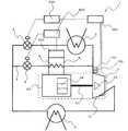
本発明の実施の形態1に係る冷凍サイクル装置1について説明する。図1は、本実施の形態1の冷凍サイクル装置1の一例を示す概略的な冷媒回路図である。なお、図1を含む以下の図面では各構成部材の寸法の関係及び形状が、実際のものとは異なる場合がある。また、以下の図面では、同一の又は類似する部材又は部分には、同一の符号を付すか、又は符号を付すことを省略している。
Embodiment 1 FIG.
Arefrigeration cycle apparatus 1 according toEmbodiment 1 of the present invention will be described. FIG. 1 is a schematic refrigerant circuit diagram illustrating an example of therefrigeration cycle apparatus 1 according to the first embodiment. In the following drawings including FIG. 1, the dimensional relationship and shape of each component may be different from the actual one. Moreover, in the following drawings, the same code | symbol is attached | subjected to the same or similar member or part, or the code | symbol is abbreviate | omitted.

本実施の形態1の冷凍サイクル装置1は、開放型の冷媒圧縮機2と、凝縮器3と、第1の減圧装置4と、第1の冷却器5とが冷媒配管を介して接続され、内部に冷媒を循環させる冷凍サイクルを備える。  In therefrigeration cycle apparatus 1 according to the first embodiment, an open-type refrigerant compressor 2, acondenser 3, afirst decompression device 4, and a first cooler 5 are connected via a refrigerant pipe. A refrigeration cycle that circulates refrigerant inside is provided.

開放型の冷媒圧縮機2は、第1の筐体21の内部に収容された圧縮機構部22と、第2の筐体23の内部に収容された電動機24とを有し、第1の筐体21と第2の筐体23とが別体として構成された、周波数可変型の流体機械である。開放型の冷媒圧縮機2においては、電動機24の回転による駆動力が、回転軸、軸継手、ギヤ、スプライン継手、ベルト駆動等の動力伝達機構25によって圧縮機構部22に伝達される。すなわち、開放型の冷媒圧縮機2では、動力伝達機構25によって伝達された電動機24の回転による駆動力によって、圧縮機構部22が駆動され、吸入した低圧冷媒が圧縮され、高圧冷媒として吐出される。電動機24は、例えばDCブラシレスモータとして構成される。  The open-type refrigerant compressor 2 includes acompression mechanism unit 22 housed in thefirst housing 21 and anelectric motor 24 housed in thesecond housing 23. This is a variable frequency fluid machine in which thebody 21 and thesecond housing 23 are configured as separate bodies. In the opentype refrigerant compressor 2, the driving force generated by the rotation of theelectric motor 24 is transmitted to thecompression mechanism unit 22 by apower transmission mechanism 25 such as a rotating shaft, a shaft joint, a gear, a spline joint, and a belt drive. That is, in the open-type refrigerant compressor 2, thecompression mechanism portion 22 is driven by the driving force generated by the rotation of theelectric motor 24 transmitted by thepower transmission mechanism 25, and the sucked low-pressure refrigerant is compressed and discharged as high-pressure refrigerant. . Theelectric motor 24 is configured as a DC brushless motor, for example.

凝縮器3は、冷媒圧縮機2から吐出された高圧冷媒と、外気(例えば、冷凍サイクル装置1が冷凍機である場合は、室外空気)との熱交換を実施し、冷媒から外気に対して熱を放出する熱交換器である。凝縮器3は、例えば、室外ファン(図示せず)によって送られてくる外気に対して熱を放出することができる。凝縮器3は、例えば、伝熱管と複数のフィンとにより構成されたクロスフィン式のフィン・アンド・チューブ型熱交換器として構成できる。  Thecondenser 3 performs heat exchange between the high-pressure refrigerant discharged from therefrigerant compressor 2 and the outside air (for example, outdoor air when therefrigeration cycle apparatus 1 is a refrigeration machine). It is a heat exchanger that releases heat. Thecondenser 3 can release heat to the outside air sent by an outdoor fan (not shown), for example. Thecondenser 3 can be configured as, for example, a cross fin type fin-and-tube heat exchanger composed of a heat transfer tube and a plurality of fins.

第1の減圧装置4は、凝縮器3から流出した高圧液冷媒を膨張及び減圧させるものである。第1の減圧装置4としては、例えば、リニア電子膨張弁等の多段階又は連続的に開度を調整可能な電子膨張弁が用いられる。  Thefirst decompression device 4 expands and decompresses the high-pressure liquid refrigerant that has flowed out of thecondenser 3. As the firstpressure reducing device 4, for example, an electronic expansion valve whose opening degree can be adjusted in multiple stages or continuously, such as a linear electronic expansion valve, is used.

第1の冷却器5は、第1の減圧装置4によって減圧された冷媒と、空気(例えば、冷凍サイクル装置1が冷凍機である場合は、室内空気)との熱交換を実施し、冷媒によって空気を冷却する熱交換器である。第1の冷却器5は、例えば、室内ファン(図示せず)によって送られてくる外気に対して熱を放出することができる。第1の冷却器5は、例えば、伝熱管と複数のフィンとにより構成されたクロスフィン式のフィン・アンド・チューブ型熱交換器として構成できる。  The first cooler 5 performs heat exchange between the refrigerant decompressed by thefirst decompression device 4 and air (for example, indoor air when therefrigeration cycle apparatus 1 is a refrigerator). It is a heat exchanger that cools air. The 1st cooler 5 can discharge | release heat with respect to the open air sent, for example by an indoor fan (not shown). The 1st cooler 5 can be comprised as a cross fin type fin and tube type heat exchanger comprised by the heat exchanger tube and the several fin, for example.

次に、本実施の形態1の冷凍サイクル装置1におけるインバータ6について、図1とともに図2を用いて説明する。図2は、本実施の形態1の冷凍サイクル装置1における、インバータ6の概略的な内部回路図である。  Next, theinverter 6 in therefrigeration cycle apparatus 1 of the first embodiment will be described with reference to FIG. 1 and FIG. FIG. 2 is a schematic internal circuit diagram of theinverter 6 in therefrigeration cycle apparatus 1 of the first embodiment.

図1に示すように、本実施の形態1の冷凍サイクル装置1は、冷媒圧縮機2の電動機24に交流電力を供給するインバータ6を備えている。図2に示すように、インバータ6においては、整流回路61、平滑コンデンサ63、及びインバータ回路64が並列に接続され、整流回路61の陽極側と平滑コンデンサ63の陽極側との間には、直流リアクトル62が接続されている。また、インバータ6においては、抵抗器65及びコンタクタ66が並列に接続されており、整流回路61の陽極側と直流リアクトル62との間に配置されている。  As shown in FIG. 1, therefrigeration cycle apparatus 1 of the first embodiment includes aninverter 6 that supplies AC power to theelectric motor 24 of therefrigerant compressor 2. As shown in FIG. 2, in theinverter 6, arectifier circuit 61, asmoothing capacitor 63, and aninverter circuit 64 are connected in parallel, and a direct current is connected between the anode side of therectifier circuit 61 and the anode side of thesmoothing capacitor 63. Areactor 62 is connected. In theinverter 6, aresistor 65 and acontactor 66 are connected in parallel, and are arranged between the anode side of therectifier circuit 61 and theDC reactor 62.

整流回路61は、例えば、整流ダイオード61aを6個ブリッジ接続して構成された三相全波整流器を構成する回路である。なお、整流回路61に交流電圧を供給する交流電源70は、例えばAC200V又はAC400Vの商用の三相交流電源である。  Therectifier circuit 61 is, for example, a circuit that constitutes a three-phase full-wave rectifier configured by connecting sixrectifier diodes 61a in a bridge connection. TheAC power supply 70 that supplies an AC voltage to therectifier circuit 61 is, for example, a commercial three-phase AC power supply of AC200V or AC400V.

直流リアクトル62は、整流回路61で整流された出力電圧から高周波の交流成分を除去するものである。  TheDC reactor 62 removes a high-frequency AC component from the output voltage rectified by therectifier circuit 61.

平滑コンデンサ63は、整流回路61で整流された出力電圧を平滑化するとともに、整流回路61からの出力電力を充電するものである。  Thesmoothing capacitor 63 smoothes the output voltage rectified by therectifier circuit 61 and charges the output power from therectifier circuit 61.

インバータ回路64は、平滑コンデンサ63によって平滑された電圧(直流母線電圧)を、例えば、三相交流電力に変換し、電動機24に供給するものである。インバータ回路64は、例えば、三相ブリッジ接続された6個のインバータ用スイッチング素子64aを備えている。また、各々のインバータ用スイッチング素子64aの両端には、逆向きに流れるモータ電流を環流させ、逆向きに流れるモータ電流からインバータ用スイッチング素子64aを保護するためのインバータ用逆流防止素子64bがそれぞれ並列接続されている。インバータ用逆流防止素子64bには、例えば、整流ダイオード、ショットキーバリアダイオード等のフライホイールダイオードが用いられる。  Theinverter circuit 64 converts the voltage (DC bus voltage) smoothed by thesmoothing capacitor 63 into, for example, three-phase AC power and supplies it to themotor 24. Theinverter circuit 64 includes, for example, sixinverter switching elements 64a connected in a three-phase bridge. Further, at both ends of eachinverter switching element 64a, a reversecurrent prevention element 64b for inverter for protecting theinverter switching element 64a from the motor current flowing in the reverse direction is circulated in parallel. It is connected. For the inverterbackflow prevention element 64b, for example, a flywheel diode such as a rectifier diode or a Schottky barrier diode is used.

抵抗器65及びコンタクタ66は、交流電源70からの電力供給開始直後の大きな突入電流の発生により、インバータ6が故障することを防ぐものである。  Theresistor 65 and thecontactor 66 prevent theinverter 6 from being damaged due to generation of a large inrush current immediately after the start of power supply from theAC power supply 70.

なお、インバータ6は、第2の筐体23の内部に収容して、電動機24を一体として構成してもよい。  Note that theinverter 6 may be housed in thesecond casing 23 and theelectric motor 24 may be integrated.

次に、冷媒によりインバータ6を冷却するための冷却機構について図1及び図2を用いて説明する。  Next, a cooling mechanism for cooling theinverter 6 with the refrigerant will be described with reference to FIGS. 1 and 2.

図1に示すように、本実施の形態1の冷凍サイクル装置1は、バイパス冷媒配管7と、第2の減圧装置8と、第2の冷却器9とを備えている。  As shown in FIG. 1, therefrigeration cycle apparatus 1 according to the first embodiment includes abypass refrigerant pipe 7, asecond decompression device 8, and a second cooler 9.

バイパス冷媒配管7は、凝縮器3と前記第1の減圧装置4との間の冷媒配管から分岐し、第1の冷却器5と冷媒圧縮機2との間の冷媒配管に連結される冷媒配管である。  The bypass refrigerant pipe 7 branches from the refrigerant pipe between thecondenser 3 and the firstpressure reducing device 4 and is connected to the refrigerant pipe between the first cooler 5 and therefrigerant compressor 2. It is.

第2の減圧装置8は、バイパス冷媒配管7に配置されており、凝縮器3から流出し、バイパス冷媒配管7を流れる高圧液冷媒を膨張及び減圧させるものである。第2の減圧装置8としては、例えば、リニア電子膨張弁等の多段階又は連続的に開度を調整可能な電子膨張弁が用いられる。なお、第2の減圧装置8は、第1の減圧装置4と同一の構成のものとしてもよいし、異なる構成のものとしてもよい。  Thesecond decompression device 8 is disposed in thebypass refrigerant pipe 7 and expands and decompresses the high-pressure liquid refrigerant that flows out of thecondenser 3 and flows through thebypass refrigerant pipe 7. As the secondpressure reducing device 8, for example, an electronic expansion valve whose opening degree can be adjusted in multiple stages or continuously, such as a linear electronic expansion valve, is used. Thesecond decompression device 8 may have the same configuration as thefirst decompression device 4, or may have a different configuration.

第2の冷却器9は、図1、2に概略的に示すように、第2の減圧装置8の出口側のバイパス冷媒配管7に、インバータ6を冷却可能なように配置される。第2の冷却器9は、第2の減圧装置8によって減圧された冷媒と、インバータ6から放出される熱との熱交換を実施し、冷媒によってインバータ6を冷却する熱交換器である。第2の冷却器9は、例えば、伝熱管と複数のフィンとにより構成されたクロスフィン式のフィン・アンド・チューブ型熱交換器として構成できる。第2の冷却器9は、インバータ6からの熱を効率良く放出可能な任意の位置に配置される。例えば、インバータ6を筐体(図示せず)に接触させて収容した場合、第2の冷却器9は、インバータ6が接触した筐体の部分に配置できる。なお、第2の冷却器9は、第1の冷却器5と同一の構成のものとしてもよいし、異なる構成のものとしてもよい。  As shown schematically in FIGS. 1 and 2, the second cooler 9 is disposed in the bypassrefrigerant pipe 7 on the outlet side of thesecond decompression device 8 so that theinverter 6 can be cooled. The second cooler 9 is a heat exchanger that performs heat exchange between the refrigerant decompressed by thesecond decompression device 8 and the heat released from theinverter 6 and cools theinverter 6 with the refrigerant. The 2nd cooler 9 can be constituted as a cross fin type fin and tube type heat exchanger constituted by a heat exchanger tube and a plurality of fins, for example. The 2nd cooler 9 is arrange | positioned in the arbitrary positions which can discharge | release the heat | fever from theinverter 6 efficiently. For example, when theinverter 6 is housed in contact with a housing (not shown), the second cooler 9 can be disposed in the portion of the housing in contact with theinverter 6. The second cooler 9 may have the same configuration as the first cooler 5 or may have a different configuration.

次に、本実施の形態1に係る冷凍サイクル装置1に配置されるセンサについて説明する。  Next, the sensor arrange | positioned at the refrigerating-cycle apparatus 1 which concerns on thisEmbodiment 1 is demonstrated.

本実施の形態1に係る冷凍サイクル装置1は、第1の温度センサ100と、圧力センサ150と、第2の温度センサ200とを備える。  Therefrigeration cycle apparatus 1 according toEmbodiment 1 includes afirst temperature sensor 100, apressure sensor 150, and asecond temperature sensor 200.

第1の温度センサ100は、第1の冷却器5と冷媒圧縮機2との間のバイパス冷媒配管7の連結位置と、冷媒圧縮機2の吸入口との間に位置する冷媒配管に配置され、冷媒圧縮機2に吸入される冷媒の温度を冷媒配管を介して検知する吸入温度センサである。圧力センサ150は、第1の温度センサ100と同様に、第1の冷却器5と冷媒圧縮機2との間のバイパス冷媒配管7の連結位置と、冷媒圧縮機2の吸入口との間に位置する冷媒配管に配置され、冷媒圧縮機2への冷媒の吸入圧力を検知する吸入圧力センサである。第2の温度センサ200は、第2の冷却器9の内部を流れる冷媒の温度(以降、「冷却温度」と称する。)を第2の冷却器9を介して検知する冷却温度センサである。  Thefirst temperature sensor 100 is disposed in a refrigerant pipe positioned between the connection position of the bypassrefrigerant pipe 7 between the first cooler 5 and therefrigerant compressor 2 and the suction port of therefrigerant compressor 2. The suction temperature sensor detects the temperature of the refrigerant sucked into therefrigerant compressor 2 through the refrigerant pipe. Similar to thefirst temperature sensor 100, thepressure sensor 150 is provided between the connection position of the bypassrefrigerant pipe 7 between the first cooler 5 and therefrigerant compressor 2 and the suction port of therefrigerant compressor 2. This is a suction pressure sensor that is arranged in the refrigerant pipe positioned and detects the suction pressure of the refrigerant to therefrigerant compressor 2. Thesecond temperature sensor 200 is a cooling temperature sensor that detects the temperature of the refrigerant flowing in the second cooler 9 (hereinafter referred to as “cooling temperature”) via the second cooler 9.

第1の温度センサ100及び第2の温度センサ200の材料としては、半導体(例えば、サーミスタ)又は金属(例えば、測温抵抗体)等が用いられる。なお、第1の温度センサ100及び第2の温度センサ200は、同一の材料で構成してもよいし、異なる材料で構成してもよい。また、圧力センサ150としては、水晶圧電式圧力センサ、半導体センサ、又は圧力トランスデューサ等が用いられる。  As a material of thefirst temperature sensor 100 and thesecond temperature sensor 200, a semiconductor (for example, a thermistor) or a metal (for example, a resistance temperature detector) is used. Note that thefirst temperature sensor 100 and thesecond temperature sensor 200 may be made of the same material or different materials. Further, as thepressure sensor 150, a crystal piezoelectric pressure sensor, a semiconductor sensor, a pressure transducer, or the like is used.

次に、本実施の形態1に係る冷凍サイクル装置1を制御する制御装置等について説明する。  Next, a control device for controlling therefrigeration cycle apparatus 1 according toEmbodiment 1 will be described.

本実施の形態1に係る冷凍サイクル装置1は、第1の減圧装置4の開度を調整する第1の制御部300と、第2の減圧装置8の開度を制御する第2の制御部400とを備える。  Therefrigeration cycle apparatus 1 according to the first embodiment includes afirst control unit 300 that adjusts the opening degree of thefirst decompression device 4, and a second control unit that controls the opening degree of thesecond decompression device 8. 400.

また、冷凍サイクル装置1は、第1の温度センサ100で検知した吸入温度と、圧力センサ150で検知した吸入圧力とから冷凍サイクルの過熱度を算出する演算部350を備える。  In addition, therefrigeration cycle apparatus 1 includes acalculation unit 350 that calculates the degree of superheat of the refrigeration cycle from the intake temperature detected by thefirst temperature sensor 100 and the intake pressure detected by thepressure sensor 150.

第1の制御部300、演算部350、及び第2の制御部400は、CPU、メモリ(例えば、ROM、RAM等)、I/Oポート等を備えたマイクロコンピュータを有している。なお、第1の制御部300及び第2の制御部400は、相互にデータ通信を行うことができるように構成してもよいし、一体の制御装置として統合して構成してもよい。  Thefirst control unit 300, thecalculation unit 350, and thesecond control unit 400 include a microcomputer that includes a CPU, a memory (eg, ROM, RAM, etc.), an I / O port, and the like. Thefirst control unit 300 and thesecond control unit 400 may be configured to perform data communication with each other, or may be configured as an integrated control device.

第1の制御部300は、第1の減圧装置4の開度の調整により、冷凍サイクルの過熱度を一定(第1の目標値)の範囲、例えば5〜10℃に制御するものである。第1の制御部300は、演算部350で算出された冷凍サイクルの過熱度に基づいて、第1の減圧装置4の開度を調整するフィードバック制御系を構成する。演算部350において、冷凍サイクルの過熱度は、圧力センサ150で検知した吸入圧力から蒸発温度(飽和温度)を換算し、第1の温度センサ100で検知した吸入温度から蒸発温度を減算することにより算出される。なお、演算部350は、第1の制御部300と別体で構成してもよいし、第1の制御部300の内部に構成してもよい。  Thefirst control unit 300 controls the degree of superheat of the refrigeration cycle within a constant (first target value) range, for example, 5 to 10 ° C., by adjusting the opening degree of thefirst decompression device 4. Thefirst control unit 300 constitutes a feedback control system that adjusts the opening of thefirst decompression device 4 based on the degree of superheat of the refrigeration cycle calculated by thecalculation unit 350. In thecalculation unit 350, the degree of superheat of the refrigeration cycle is calculated by converting the evaporation temperature (saturation temperature) from the suction pressure detected by thepressure sensor 150 and subtracting the evaporation temperature from the suction temperature detected by thefirst temperature sensor 100. Calculated. Thecalculation unit 350 may be configured separately from thefirst control unit 300 or may be configured inside thefirst control unit 300.

第2の制御部400は、第2の減圧装置8の開度の調整により、第2の冷却器9の冷却温度を一定(第2の目標値)の範囲、例えば−35〜−25℃に制御するものである。第1の制御部300は、演算部350で算出された冷凍サイクルの過熱度に基づいて、第1の減圧装置4の開度を調整するフィードバック制御系を構成する。  Thesecond control unit 400 adjusts the opening degree of thesecond decompression device 8 so that the cooling temperature of the second cooler 9 is in a constant (second target value) range, for example, −35 to −25 ° C. It is something to control. Thefirst control unit 300 constitutes a feedback control system that adjusts the opening of thefirst decompression device 4 based on the degree of superheat of the refrigeration cycle calculated by thecalculation unit 350.

次に、本実施の形態1に係る冷凍サイクル装置1の動作について、インバータ6の動作とともに説明する。  Next, the operation of therefrigeration cycle apparatus 1 according to the first embodiment will be described together with the operation of theinverter 6.

冷媒圧縮機2から吐出された高温高圧のガス冷媒は、凝縮器3へ流入する。凝縮器3に流入した高温高圧のガス冷媒は、室外空気等の低温の媒体に熱を放出することによって熱交換され、液冷媒となる。凝縮器3で熱交換された液冷媒は、第1の減圧装置4へ流入し、膨張及び減圧されて低温低圧の二相冷媒となる。第1の減圧装置4から流出した低温低圧の気液二相冷媒は、第1の冷却器5に流入する。第1の冷却器5に流入した気液二相冷媒は、室内空気等を冷却(吸熱)し、蒸発して乾き度の高い二相冷媒又は低温低圧のガス冷媒となる。  The high-temperature and high-pressure gas refrigerant discharged from therefrigerant compressor 2 flows into thecondenser 3. The high-temperature and high-pressure gas refrigerant that has flowed into thecondenser 3 is heat-exchanged by releasing heat to a low-temperature medium such as outdoor air, and becomes a liquid refrigerant. The liquid refrigerant heat-exchanged in thecondenser 3 flows into thefirst decompression device 4 and is expanded and decompressed to become a low-temperature and low-pressure two-phase refrigerant. The low-temperature and low-pressure gas-liquid two-phase refrigerant that has flowed out of thefirst decompression device 4 flows into the first cooler 5. The gas-liquid two-phase refrigerant that has flowed into the first cooler 5 cools (endothermics) indoor air and the like, evaporates, and becomes a two-phase refrigerant having a high degree of dryness or a low-temperature and low-pressure gas refrigerant.

一方、交流電源70によりインバータ6に供給された交流電圧は、整流回路61で整流され、直流リアクトル62及び平滑コンデンサ63に出力される。整流回路61からの出力電圧は、直流リアクトル62で高周波の交流成分が除去され、平滑コンデンサ63で平滑化されるとともに充電される。平滑コンデンサ63からの出力電圧は、インバータ回路64で任意の周波数の交流電圧に変換され、変換された交流電圧の周波数に応じて電動機24の回転数が制御される。なお、交流電流に変換する際に発生するリップル電流は、平滑コンデンサ63で吸収される。  On the other hand, the AC voltage supplied to theinverter 6 by theAC power source 70 is rectified by therectifier circuit 61 and output to theDC reactor 62 and the smoothingcapacitor 63. The output voltage from therectifier circuit 61 is removed from the high-frequency AC component by theDC reactor 62, smoothed by the smoothingcapacitor 63 and charged. The output voltage from the smoothingcapacitor 63 is converted into an AC voltage having an arbitrary frequency by theinverter circuit 64, and the rotational speed of theelectric motor 24 is controlled according to the frequency of the converted AC voltage. Note that the ripple current generated when the AC current is converted is absorbed by the smoothingcapacitor 63.

ここで、インバータ回路64で周波数変換を行う際に整流回路61、平滑コンデンサ63、及びインバータ回路64等で発生する電気損失は、熱となり外部に放出される。また、インバータ6からの出力電力が増加するにつれて、インバータ6における電気損失は増加し、外部に放出される熱量も増加する。  Here, the electrical loss generated in therectifier circuit 61, the smoothingcapacitor 63, theinverter circuit 64, and the like when theinverter circuit 64 performs frequency conversion becomes heat and is released to the outside. Further, as the output power from theinverter 6 increases, the electrical loss in theinverter 6 increases and the amount of heat released to the outside also increases.

凝縮器3と前記第1の減圧装置4との間の冷媒配管から分岐したバイパス冷媒配管7を流れ、凝縮器3で熱交換された液冷媒は、第2の減圧装置8へ流入し、膨張及び減圧されて低温低圧の二相冷媒となる。第2の減圧装置8から流出した低温低圧の気液二相冷媒は、第2の冷却器9に流入する。第2の冷却器9に流入した気液二相冷媒は、インバータ6を冷却(吸熱)し、蒸発して乾き度の高い二相冷媒又は低温低圧のガス冷媒となる。第2の冷却器9から流出した乾き度の高い二相冷媒又は低温低圧のガス冷媒は、第1の冷却器5から流出したガス冷媒と合流し、冷媒圧縮機2に吸入される。冷媒圧縮機2に吸入された冷媒は圧縮されて、高温高圧のガス冷媒となり、冷媒圧縮機2から吐出される。冷凍サイクル装置1では以上のサイクルが繰り返される。  The liquid refrigerant that has flowed through the bypassrefrigerant pipe 7 branched from the refrigerant pipe between thecondenser 3 and thefirst decompressor 4 and exchanged heat in thecondenser 3 flows into thesecond decompressor 8 and expands. And it is decompressed to become a low-temperature and low-pressure two-phase refrigerant. The low-temperature and low-pressure gas-liquid two-phase refrigerant that has flowed out of thesecond decompression device 8 flows into the second cooler 9. The gas-liquid two-phase refrigerant flowing into the second cooler 9 cools (absorbs heat) theinverter 6 and evaporates to become a two-phase refrigerant having a high dryness or a low-temperature and low-pressure gas refrigerant. The highly dry two-phase refrigerant or the low-temperature and low-pressure gas refrigerant that has flowed out of the second cooler 9 merges with the gas refrigerant that has flowed out of the first cooler 5 and is sucked into therefrigerant compressor 2. The refrigerant sucked into therefrigerant compressor 2 is compressed to become a high-temperature and high-pressure gas refrigerant, and is discharged from therefrigerant compressor 2. In therefrigeration cycle apparatus 1, the above cycle is repeated.

なお、インバータ6において、コンタクタ66は、交流電源70からの電力供給が停止している場合に開放されており、交流電源70からの電力供給の開始後、突入電流が発生している一定の期間は、抵抗器65を介して電流が流れるように制御されている。また、コンタクタ66は、インバータ6を流れる電流が安定した後(すなわち、突入電流が流れなくなった後)に、コンタクタ66の連結で抵抗器65の両端を短絡することにより、インバータ6全体の抵抗値を低減するように制御されている。  In theinverter 6, thecontactor 66 is opened when the power supply from theAC power supply 70 is stopped, and after the start of the power supply from theAC power supply 70, the inrush current is generated for a certain period. Is controlled so that a current flows through theresistor 65. Further, thecontactor 66 short-circuits both ends of theresistor 65 by connecting thecontactor 66 after the current flowing through theinverter 6 is stabilized (that is, after the inrush current stops flowing). It is controlled to reduce.

すなわち、交流電源70からの電力供給開始後、突入電流が発生している一定の期間において、インバータ6は、インバータ6全体を流れる電流が小さくなるように制御されている。また、インバータ6を流れる電流が安定した後においては、インバータ6は、インバータ6全体を流れる電流が大きくなるように制御されている。  That is, after the start of power supply from theAC power supply 70, theinverter 6 is controlled so that the current flowing through theentire inverter 6 becomes small during a certain period in which the inrush current is generated. In addition, after the current flowing through theinverter 6 is stabilized, theinverter 6 is controlled so that the current flowing through theentire inverter 6 becomes large.

インバータ6においては、平滑コンデンサ63及びインバータ回路64の抵抗値が小さいため、交流電源70からの電力供給開始時にはインバータ6に大きな突入電流が発生し、インバータ6が破損する可能性がある。しかしながら、インバータ6に抵抗器65及びコンタクタ66を設けることによって、安定かつ効率的な電動機24への電力供給が可能となる。  In theinverter 6, since the resistance values of the smoothingcapacitor 63 and theinverter circuit 64 are small, a large inrush current may be generated in theinverter 6 when the power supply from theAC power supply 70 is started, and theinverter 6 may be damaged. However, providing theresistor 65 and thecontactor 66 in theinverter 6 enables stable and efficient power supply to theelectric motor 24.

次に、本実施の形態1に係る冷凍サイクル装置1の第1の制御部300における制御処理の例を以下の実施例1、2に説明する。  Next, examples of control processing in thefirst control unit 300 of therefrigeration cycle apparatus 1 according toEmbodiment 1 will be described in Examples 1 and 2 below.

第1の制御部300は、第1の減圧装置4の開度の調整により冷凍サイクルの過熱度を第1の目標値の範囲に制御するものである。実施例1、2では、冷凍サイクルにおける過熱度をSH、過熱度SHの目標値(第1の目標値)の範囲の下限値をSHlower、上限値をSHupper、過熱度SHの現在値をSHnowとする。また、第1の減圧装置4の開度をD1、開度D1の現在値をD1now、下限値をD1lower、上限値をD1upperとする。過熱度SHの下限値SHlower及び上限値SHupper、並びに開度D1のD1lower及び上限値D1upperのデータは、第1の制御部300が参照できるように記憶される。例えば、これらのデータは、第1の制御部300の記憶領域(図示せず)に記憶するようにしてもよいし、第1の制御部300と別に設けた記憶部に記憶するようにしてもよい。Thefirst control unit 300 controls the degree of superheat of the refrigeration cycle within the first target value range by adjusting the opening of thefirst decompression device 4. In Examples 1 and 2, the superheat degree in the refrigeration cycle is SH, the lower limit value of the target value (first target value) of the superheat degree SH is SHlower , the upper limit value is SHupper , and the current value of the superheat degree SH is SHnow be assumed. Further, the opening of thefirst decompression device 4 is D1, the current value of the opening D1 is D1now , the lower limit is D1lower , and the upper limit is D1upper . The lower limit value SHlower and the upper limit value SHupper of the superheat degree SH, and the data of the D1lower and the upper limit value D1upper of the opening degree D1 are stored so that thefirst control unit 300 can refer to them. For example, these data may be stored in a storage area (not shown) of thefirst control unit 300, or may be stored in a storage unit provided separately from thefirst control unit 300. Good.

(実施例1)
図3は、本実施の形態1に係る冷凍サイクル装置1の第1の制御部300における制御処理の一例を示すフローチャートである。図3の制御処理は、常時行うようにしてもよいし、例えば、過熱度SHの変動を検知した際に随時行うようにしてもよい。
Example 1
FIG. 3 is a flowchart illustrating an example of a control process in thefirst control unit 300 of therefrigeration cycle apparatus 1 according to the first embodiment. The control process of FIG. 3 may be performed all the time, or may be performed at any time when a change in the superheat degree SH is detected, for example.

ステップS11において、第1の制御部300は、演算部350で算出された過熱度SHの現在値SHnowが過熱度SHの上限値SHupper(例えば、10℃)以上であるか否かを判定する。In step S11, thefirst control unit 300 determines whether or not the current value SHnow of the superheat degree SH calculated by thecalculation unit 350 is equal to or higher than theupper limit value SHupper (for example, 10 ° C.) of the superheat degree SH. To do.

過熱度SHの現在値SHnowが過熱度SHの上限値SHupper以上である場合、ステップS12において、第1の制御部300は、第1の減圧装置4の開度D1を現在値D1nowよりも大きくなるように調整し、制御処理を終了する。When the current value SHnow of the superheat degree SH is equal to or higher than the upper limit value SHupper of the superheat degree SH, in step S12, thefirst control unit 300 determines the opening degree D1 of the firstpressure reducing device 4 from the current value D1now . And the control process is terminated.

過熱度SHの現在値SHnowが過熱度SHの上限値SHupper未満である場合、ステップS13において、第1の制御部300は、過熱度SHの現在値SHnowが過熱度SHの下限値SHlower(例えば、5℃)以下であるか否かを判定する。過熱度SHの現在値SHnowが過熱度SHの下限値SHlowerを超えている場合、制御処理は終了し、開度D1は現在値D1nowで維持される。If the current value SHnow of the superheat degree SH is less than the upper limit value SHupper of the superheat degree SH, in step S13, thefirst controller 300 determines that the current value SHnow of the superheat degree SH is the lower limit value SH of the superheat degree SH. It is determined whether the temperature islower (for example, 5 ° C.) or less. When the current value SHnow of the superheat degree SH exceeds thelower limit value SHlower of the superheat degree SH, the control process ends, and the opening degree D1 is maintained at the current value D1now .

過熱度SHの現在値SHnowが過熱度SHの下限値SHlower以下である場合、ステップS14において、第1の制御部300は、第1の減圧装置4の開度D1を現在値D1nowよりも小さくなるように調整し、制御処理を終了する。When the current value SHnow of the superheat degree SH is equal to orlower than the lower limit value SHlower of the superheat degree SH, in step S14, thefirst controller 300 determines the opening degree D1 of the firstpressure reducing device 4 from the current value D1now . And the control process is terminated.

(実施例2)
図4は、本実施の形態1に係る冷凍サイクル装置1の第1の制御部300における制御処理の別の一例を示すフローチャートである。図4の制御処理は、常時行うようにしてもよいし、例えば、過熱度SHの変動を検知した際に随時行うようにしてもよい。
(Example 2)
FIG. 4 is a flowchart showing another example of the control process in thefirst control unit 300 of therefrigeration cycle apparatus 1 according to the first embodiment. The control process of FIG. 4 may be performed all the time, or may be performed at any time when a change in the superheat degree SH is detected, for example.

ステップS21において、実施例1のステップS11と同様に、第1の制御部300は、過熱度SHの現在値SHnowが過熱度SHの上限値SHupper以上であるか否かを判定する。In step S21, as in step S11 of the first embodiment, thefirst control unit 300 determines whether or not the current value SHnow of the superheat degree SH is equal to or higher than the upper limit value SHupper of the superheat degree SH.

過熱度SHの現在値SHnowが過熱度SHの上限値SHupper以上である場合、ステップS22において、第1の制御部300は、第1の減圧装置4の開度D1の現在値D1nowを下限値D1lowerに設定し、制御処理を終了する。When the current value SHnow of the superheat degree SH is equal to or higher than the upper limit value SHupper of the superheat degree SH, in step S22, thefirst control unit 300 sets the current value D1now of the opening degree D1 of the firstpressure reducing device 4. The lower limit value D1lower is set, and the control process is terminated.

過熱度SHの現在値SHnowが過熱度SHの上限値SHupper未満である場合、ステップS23において、第1の制御部300は、過熱度SHの現在値SHnowが過熱度SHの下限値SHlower以下であるか否かを判定する。過熱度SHの現在値SHowが過熱度SHの下限値SHlowerを超えている場合、制御処理を終了する。If the current value SHnow of the superheat degree SH is less than the upper limit value SHupper of the superheat degree SH, in step S23, thefirst controller 300 determines that the current value SHnow of the superheat degree SH is the lower limit value SH of the superheat degree SH. It is determined whether it islower orlower . If the current valueSHn ow superheat SH is higher than the lower limit valueSH lower superheat SH, the control process is terminated.

過熱度SHの現在値SHnowが過熱度SHの下限値SHlower以下である場合、ステップS24において、第1の制御部300は、第1の減圧装置4の開度D1の現在値D1nowを上限値D1upperに設定し、制御処理を終了する。When the current value SHnow of the superheat degree SH is equal to orlower than the lower limit value SHlower of the superheat degree SH, in step S24, thefirst control unit 300 sets the current value D1now of the opening degree D1 of thefirst decompression device 4. The upper limit value D1upper is set and the control process is terminated.

なお、第1の制御部300は、実施例1及び実施例2の制御処理のいずれか一方のみを行うように構成してもよいし、双方の制御処理を行うように構成してもよい。  Thefirst control unit 300 may be configured to perform only one of the control processes of the first embodiment and the second embodiment, or may be configured to perform both control processes.

次に、本実施の形態1に係る冷凍サイクル装置1の第2の制御部400における制御処理の例を以下の実施例3、4に説明する。  Next, examples of control processing in thesecond control unit 400 of therefrigeration cycle apparatus 1 according toEmbodiment 1 will be described in Examples 3 and 4 below.

第2の制御部400は、第2の減圧装置8の開度の調整により、第2の冷却器9の冷却温度を第2の目標値の範囲に制御するものである。実施例3、4では、第2の冷却器9の冷却温度をT、冷却温度Tの目標値(第2の目標値)の範囲の下限値をTlower、上限値をTupper、冷却温度Tの現在値をTnowとする。また、第2の減圧装置8の開度をD2、開度D2の現在値をD2now、下限値をD2lower、上限値をD2pperとする。冷却温度Tの下限値Tlower及び上限値Tupper、並びに開度D2のD2lower及び上限値D2upperのデータは、第2の制御部400が参照できるように記憶される。例えば、これらのデータは、第2の制御部400の内部に設けられた記憶領域(図示せず)に記憶するようにしてもよいし、第2の制御部400と別に設けた記憶部に記憶するようにしてもよい。Thesecond control unit 400 controls the cooling temperature of the second cooler 9 within the range of the second target value by adjusting the opening of thesecond decompression device 8. In Examples 3 and 4, the cooling temperature of the second cooler 9 is T, the lower limit value of the target value (second target value) range of the cooling temperature T is Tlower , the upper limit value is Tupper , and the cooling temperature TLet Tnow be the current value of. Further, the opening degree of the secondpressure reducing device 8 D2, the current value of the opening degree D2D2 now, the lower limit valueD2 lower, the upper limit value andD2u pper. Data of thelower limit value Tlower and the upper limit value Tupper of the cooling temperature T, and the D2lower and upper limit value D2upper of the opening degree D2 are stored so that thesecond control unit 400 can refer to them. For example, these data may be stored in a storage area (not shown) provided in thesecond control unit 400 or stored in a storage unit provided separately from thesecond control unit 400. You may make it do.

(実施例3)
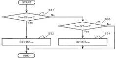
図5は、本実施の形態1に係る冷凍サイクル装置1の第2の制御部400における制御処理の一例を示すフローチャートである。図5の制御処理は、常時行うようにしてもよいし、例えば、冷却温度Tの変動を検知した際に随時行うようにしてもよい。
(Example 3)
FIG. 5 is a flowchart illustrating an example of a control process in thesecond control unit 400 of therefrigeration cycle apparatus 1 according to the first embodiment. The control process of FIG. 5 may be performed all the time, or may be performed at any time when a change in the cooling temperature T is detected, for example.

ステップS31において、第2の制御部400は、第2の温度センサ200で検知された冷却温度Tの現在値Tnowが冷却温度Tの上限値Tupper(例えば、−25℃)以上であるか否かを判定する。In step S31, thesecond control unit 400 determines whether the current valueTnow of the cooling temperature T detected by thesecond temperature sensor 200 is equal to or higher than theupper limit value Tupper (for example, −25 ° C.) of the cooling temperature T. Determine whether or not.

冷却温度Tの現在値Tnowが冷却温度Tの上限値Tupper以上である場合、ステップS32において、第2の制御部400は、第2の減圧装置8の開度D2を現在値D2nowよりも大きくなるように調整し、制御処理を終了する。  Current value T of cooling temperature TnowIs the upper limit T of the cooling temperature TupperWhen it is above, in Step S32, the2nd control part 400 sets opening degree D2 of the2nd decompression device 8 as present value D2.nowAnd the control process is terminated.

冷却温度Tの現在値Tnowが冷却温度Tの上限値Tupper未満である場合、ステップS33において、第2の制御部400は、冷却温度Tの現在値Tnowが冷却温度Tの下限値Tlower(例えば、−35℃)以下であるか否かを判定する。冷却温度Tの現在値Tnowが冷却温度Tの下限値Tlowerを超えている場合、制御処理は終了し、開度D2は現在値D2nowで維持される。If the current valueT now cooling temperature T is less than the upper limit valueT upper cooling temperature T, in step S33, thesecond controller 400, the current valueT now cooling temperature T lower limit value T of the cooling temperature T It is determined whether the temperature islower (for example, −35 ° C.) or less. If the current valueT now cooling temperature T is higher than the lower limit valueT lower cooling temperature T, the control process ends and opening D2 is maintained at a current valueD2 now.

冷却温度Tの現在値Tnowが冷却温度Tの下限値Tlower以下である場合、ステップS34において、第2の制御部400は、第2の減圧装置8の開度D2を現在値D2nowよりも小さくなるように調整し、制御処理を終了する。  Current value T of cooling temperature TnowIs the lower limit T of the cooling temperature TlowerIn the case of the following, in step S34, thesecond control unit 400 sets the opening degree D2 of thesecond decompression device 8 to the current value D2.nowThe control process is terminated after adjusting so as to be smaller.

(実施例4)
図6は、本実施の形態1に係る冷凍サイクル装置1の第2の制御部400における制御処理の別の一例を示すフローチャートである。図6の制御処理は、常時行うようにしてもよいし、例えば、冷却温度Tの変動を検知した際に随時行うようにしてもよい。
Example 4
FIG. 6 is a flowchart illustrating another example of the control process in thesecond control unit 400 of therefrigeration cycle apparatus 1 according to the first embodiment. The control process of FIG. 6 may be performed all the time, or may be performed at any time when a change in the cooling temperature T is detected, for example.

ステップS41において、実施例3のステップS31と同様に、第2の制御部400は、冷却温度Tの現在値Tnowが冷却温度Tの上限値Tupper以上であるか否かを判定する。In step S41, similarly to step S31 inEmbodiment 3, thesecond control unit 400, the current valueT now is equal to or more than the upper limit valueT upper cooling temperature T of the cooling temperature T.

冷却温度Tの現在値Tnowが冷却温度Tの上限値Tupper以上である場合、ステップS42において、第2の制御部400は、第2の減圧装置8の開度D2の現在値D2nowを下限値D2lowerに設定し、制御処理を終了する。  Current value T of cooling temperature TnowIs the upper limit T of the cooling temperature TupperWhen it is above, in step S42, the2nd control part 400 is the present value D2 of the opening degree D2 of the2nd decompression device 8.nowIs the lower limit D2lowerTo complete the control process.

冷却温度Tの現在値Tnowが冷却温度Tの上限値Tupper未満である場合、ステップS43において、第2の制御部400は、冷却温度Tの現在値Tnowが冷却温度Tの下限値Tlower以下であるか否かを判定する。冷却温度Tの現在値Tnowが冷却温度Tの下限値Tlowerを超えている場合、制御処理を終了する。If the current valueT now cooling temperature T is less than the upper limit valueT upper cooling temperature T, in step S43, thesecond controller 400, the current valueT now cooling temperature T lower limit value T of the cooling temperature T It is determined whether it islower orlower . When the current valueTnow of the cooling temperature T exceeds thelower limit valueTlower of the cooling temperature T, the control process is terminated.

冷却温度Tの現在値Tnowが冷却温度Tの下限値Tlower以下である場合、ステップS44において、第2の制御部400は、第2の減圧装置8の開度D2の現在値D2nowを上限値D2upperに設定し、制御処理を終了する。  Current value T of cooling temperature TnowIs the lower limit T of the cooling temperature TlowerWhen it is below, in step S44, the2nd control part 400 is the present value D2 of the opening degree D2 of the2nd decompression device 8.nowIs the upper limit D2upperTo complete the control process.

なお、第2の制御部400は、実施例3及び実施例4の制御処理のいずれか一方のみを行うように構成してもよいし、双方の制御処理を行うように構成してもよい。  Thesecond control unit 400 may be configured to perform only one of the control processes of the third embodiment and the fourth embodiment, or may be configured to perform both control processes.

以下に、本実施の形態1による本発明の効果を説明する。  The effects of the present invention according to the first embodiment will be described below.

上述したとおり、本実施の形態1に係る冷凍サイクル装置1は、第1の筐体21の内部に収容された圧縮機構部22と、第2の筐体23の内部に収容された電動機24とを有し、第1の筐体21と第2の筐体23とが別体として構成された開放型の冷媒圧縮機2と、凝縮器3と、第1の減圧装置4と、第1の冷却器5とが冷媒配管を介して接続され、内部に冷媒を循環させる冷凍サイクルと、電動機24に交流電力を供給するインバータ6と、凝縮器3と第1の減圧装置4との間の冷媒配管から分岐し、第1の冷却器5と冷媒圧縮機2との間の冷媒配管に連結されるバイパス冷媒配管7と、バイパス冷媒配管7に配置された第2の減圧装置8と、第2の減圧装置8の出口側のバイパス冷媒配管7に配置され、インバータ6を冷却する第2の冷却器9と、第1の減圧装置4の開度を調整する第1の制御部300と、第2の減圧装置8の開度を制御する第2の制御部400とを備え、第1の制御部300は、第1の減圧装置4の開度の調整により、冷凍サイクルの過熱度を第1の目標値の範囲に制御し、第2の制御部400は、第2の減圧装置8の開度の調整により、第2の冷却器9の冷却温度を第2の目標値の範囲に制御するものである。  As described above, therefrigeration cycle apparatus 1 according toEmbodiment 1 includes thecompression mechanism unit 22 housed in thefirst housing 21 and theelectric motor 24 housed in thesecond housing 23. An open-type refrigerant compressor 2, acondenser 3, afirst decompression device 4, afirst casing 21 and asecond casing 23, which are configured separately. A refrigerating cycle connected to the cooler 5 via a refrigerant pipe and circulating the refrigerant therein, aninverter 6 that supplies AC power to theelectric motor 24, and a refrigerant between thecondenser 3 and the first decompressor 4 Abypass refrigerant pipe 7 branched from the pipe and connected to a refrigerant pipe between the first cooler 5 and therefrigerant compressor 2, asecond decompression device 8 disposed in the bypassrefrigerant pipe 7, and a second Thesecond cooling unit 7 is disposed in the bypassrefrigerant pipe 7 on the outlet side of thedecompression device 8 and cools theinverter 6. Afirst control unit 300 that adjusts the opening degree of thefirst decompression device 4 and asecond control unit 400 that controls the opening degree of thesecond decompression device 8. Theunit 300 controls the degree of superheating of the refrigeration cycle to the range of the first target value by adjusting the opening degree of the firstpressure reducing device 4, and thesecond control unit 400 opens the secondpressure reducing device 8. By adjusting the degree, the cooling temperature of the second cooler 9 is controlled within the range of the second target value.

従来、部分負荷効率の向上を目的とした、インバータにより冷媒圧縮機の運転周波数制御を行う冷凍サイクル装置が知られている。このような冷凍サイクル装置では、インバータの出力電力が増加すると、インバータ出力電力の増加に比例して、インバータからの発熱が増加するため、インバータからの発熱を拡散させ冷却する必要がある。  2. Description of the Related Art Conventionally, a refrigeration cycle apparatus that performs operation frequency control of a refrigerant compressor with an inverter for the purpose of improving partial load efficiency is known. In such a refrigeration cycle apparatus, when the output power of the inverter increases, the heat generation from the inverter increases in proportion to the increase in the inverter output power. Therefore, it is necessary to diffuse and cool the heat generation from the inverter.

従来のインバータの冷却方法としては、インバータからの発熱を拡散させるために整流回路等にヒートシンク等を取り付け、インバータの周囲の空気をヒートシンク等に送風し、ヒートシンク等を冷却する方法が採用されていた。しかしながら、送風によりインバータを冷却する方法では、冷却風量を確保するために、大きな送風ファンや大きな冷却風路が必要となる。また、冷凍サイクル装置におけるインバータの出力電力が大きくなるにつれて、必要な冷却風量も増加するため、冷凍サイクル装置の設計上の制約も多くなる。  As a conventional inverter cooling method, a method of attaching a heat sink or the like to a rectifier circuit or the like to diffuse the heat generated from the inverter, blowing air around the inverter to the heat sink or the like, and cooling the heat sink or the like has been adopted. . However, in the method of cooling the inverter by blowing air, a large blower fan and a large cooling air passage are required to secure the cooling air volume. In addition, as the output power of the inverter in the refrigeration cycle apparatus increases, the required amount of cooling air also increases, which increases the design restrictions of the refrigeration cycle apparatus.

冷凍サイクル装置の設計上の制約を解消する方法としては、冷媒によりインバータを冷却する方法がある。冷媒によりインバータを冷却する方法では、ファンや冷却風路が不要となるため、冷凍サイクル装置の設計上の制約を解消することができる。冷媒によりインバータを冷却する方法としては、減圧装置を制御することによる冷却方法、インバータ冷却のための専用の冷却回路を設けない冷却方法が知られている。  As a method of eliminating the design restrictions of the refrigeration cycle apparatus, there is a method of cooling the inverter with a refrigerant. In the method of cooling the inverter with the refrigerant, a fan and a cooling air passage are not necessary, and thus the design restrictions of the refrigeration cycle apparatus can be eliminated. As a method of cooling an inverter with a refrigerant, a cooling method by controlling a decompression device and a cooling method without providing a dedicated cooling circuit for inverter cooling are known.

しかしながら、冷媒によりインバータを冷却する従来の方法では、インバータを冷却した冷媒が冷凍サイクルを流れる冷媒と合流して冷媒圧縮機に吸入されるため、冷媒圧縮機に吸入される冷媒の温度はインバータを冷却した冷媒の温度に依存することとなる。したがって、冷媒によりインバータを冷却する従来の方法を採用した冷凍サイクル装置では、冷媒圧縮機に吸入される冷媒が液冷媒又は過熱度の高いガス冷媒となり、冷媒圧縮機の安定した運転状態が確保できない場合があるという問題点があった。  However, in the conventional method in which the inverter is cooled by the refrigerant, the refrigerant that has cooled the inverter joins the refrigerant flowing through the refrigeration cycle and is sucked into the refrigerant compressor. It depends on the temperature of the cooled refrigerant. Therefore, in the refrigeration cycle apparatus that employs the conventional method of cooling the inverter with the refrigerant, the refrigerant sucked into the refrigerant compressor becomes a liquid refrigerant or a gas refrigerant with a high degree of superheat, and a stable operation state of the refrigerant compressor cannot be secured. There was a problem that there was a case.

また、中間インジェクション機構等を流れる冷媒によってインバータの冷却を行う、すなわち、冷媒圧縮機が吸入する冷媒によってインバータの冷却を行わない冷凍サイクル装置も知られている。しかしながら、このような冷凍サイクル装置では、インバータを冷却するための制御方法が示されていないため、冷媒の流量不足によるインバータの過熱、又は冷媒の流量過剰によるインバータの結露が発生する場合がある。したがって、このような冷凍サイクル装置では、インバータが損傷する可能性があるという問題点があった。  There is also known a refrigeration cycle apparatus that cools an inverter with refrigerant flowing through an intermediate injection mechanism or the like, that is, does not cool an inverter with refrigerant sucked by a refrigerant compressor. However, in such a refrigeration cycle apparatus, since a control method for cooling the inverter is not shown, the inverter may be overheated due to insufficient refrigerant flow rate, or the inverter may be condensed due to excessive refrigerant flow rate. Therefore, such a refrigeration cycle apparatus has a problem that the inverter may be damaged.

これに対し、本実施の形態1によれば、第1の制御部300は、第1の減圧装置4の開度を調整することにより、冷媒圧縮機2が吸入する冷媒の流量を調整でき、冷凍サイクルの過熱度を一定の範囲(第1の目標値の範囲)に制御できる。よって、冷凍サイクルの過熱度を第1の目標値の範囲に制御することにより、冷媒圧縮機2の圧縮機構部22が液冷媒を吸入することも、過熱度の大きいガス冷媒を吸入することも回避できる。  On the other hand, according to the first embodiment, thefirst controller 300 can adjust the flow rate of the refrigerant sucked by therefrigerant compressor 2 by adjusting the opening degree of thefirst decompression device 4, The degree of superheat of the refrigeration cycle can be controlled within a certain range (first target value range). Therefore, by controlling the degree of superheat of the refrigeration cycle to the range of the first target value, thecompression mechanism 22 of therefrigerant compressor 2 can inhale liquid refrigerant or can inhale gas refrigerant with high degree of superheat. Can be avoided.

また、本実施の形態1によれば、第2の制御部400は、第2の減圧装置8の開度を調整することにより、インバータを冷却する第2の冷却器9を流れる冷媒の流量を調整でき、第2の冷却器9の冷却温度を一定の範囲(第2の目標値の範囲)に制御できる。よって、第2の冷却器9の冷却温度を第2の目標値の範囲に制御することにより、第2の冷却器9を流れる冷媒の流量不足によるインバータ6の過熱も、第2の冷却器9を流れる冷媒の流量過剰によるインバータ6の結露も回避することができる。  Further, according to the first embodiment, thesecond control unit 400 adjusts the opening degree of thesecond decompression device 8, thereby adjusting the flow rate of the refrigerant flowing through the second cooler 9 that cools the inverter. The cooling temperature of the second cooler 9 can be controlled within a certain range (second target value range). Therefore, by controlling the cooling temperature of the second cooler 9 within the range of the second target value, the overheating of theinverter 6 due to the insufficient flow rate of the refrigerant flowing through the second cooler 9 can also be prevented. Condensation of theinverter 6 due to an excessive flow rate of the refrigerant flowing through can also be avoided.

したがって、本実施の形態1によれば、冷媒圧縮機2の信頼性が確保でき、冷凍サイクル装置1の効率的な運転ができるとともに、インバータ6の損傷を回避し、信頼性を確保することができる。また、冷凍サイクル装置1の効率的な運転によりエネルギー消費量を削減できるとともに、冷媒圧縮機2及びインバータ6の耐久性を向上させることができる。  Therefore, according to the first embodiment, the reliability of therefrigerant compressor 2 can be ensured, therefrigeration cycle apparatus 1 can be efficiently operated, the damage to theinverter 6 can be avoided, and the reliability can be ensured. it can. Further, the energy consumption can be reduced by the efficient operation of therefrigeration cycle apparatus 1, and the durability of therefrigerant compressor 2 and theinverter 6 can be improved.

また、インバータ6に設けられた平滑コンデンサ63は温度の低下に伴い、吸収可能なリップル電流が増加するという特性を有する。したがって、本実施の形態1において、第2の冷却器9の冷却温度の温度範囲を、例えば−35℃を上限とする低い温度に制御することで、平滑コンデンサ63として容量の小さいものを選定できる。したがって、インバータ6の製造コストを低減し、環境負荷を軽減できるという利点も有する。  Further, the smoothingcapacitor 63 provided in theinverter 6 has a characteristic that the ripple current that can be absorbed increases as the temperature decreases. Therefore, in the first embodiment, the smoothingcapacitor 63 having a small capacity can be selected by controlling the temperature range of the cooling temperature of the second cooler 9 to a low temperature having an upper limit of −35 ° C., for example. . Therefore, there is an advantage that the manufacturing cost of theinverter 6 can be reduced and the environmental load can be reduced.

また、本実施の形態1の冷凍サイクル装置1は、地球温暖化係数が低く、燃焼性を有する冷媒の使用を考慮した構成となっているため、冷凍サイクル装置1を安全に使用することができるという利点も有する。  In addition, therefrigeration cycle apparatus 1 according to the first embodiment has a low global warming potential and a configuration that takes into account the use of a flammable refrigerant, so that therefrigeration cycle apparatus 1 can be used safely. It also has the advantage of.

近年、昨今の地球温暖化問題に対応して、冷凍サイクル装置で使用する冷媒においては、地球温暖化係数が低い冷媒(以下、「低GWP冷媒」と称する。)を実用化する動きが欧州を皮切りに活発化している。  In recent years, in response to the recent global warming problem, in the refrigerant used in the refrigeration cycle apparatus, the movement of putting a refrigerant having a low global warming coefficient (hereinafter referred to as “low GWP refrigerant”) into practical use in Europe. It is becoming more active.

一方、低GWP冷媒には、CF−CF=CH(HFO1234yf)及びCH(R32)等の燃焼性を有する冷媒がある。燃焼性のある低GWP冷媒を用いる場合、空調装置及び冷凍機等の冷凍サイクル装置においては、安全上の制約から、電動機等の電気機器を冷媒雰囲気内に配置することができない。  On the other hand, CF for low GWP refrigerant3-CF = CH2(HFO1234yf) and CH2F2There is a refrigerant having combustibility such as (R32). In the case of using a combustible low GWP refrigerant, in a refrigeration cycle apparatus such as an air conditioner or a refrigerator, an electric device such as an electric motor cannot be disposed in the refrigerant atmosphere due to safety restrictions.

これに対して、本実施の形態1に係る冷凍サイクル装置1は、開放型の冷媒圧縮機2を備えている。すなわち、本実施の形態1の冷媒圧縮機2では、圧縮機構部22を収容した第1の筐体21、及び電動機24を収容した第2の筐体23は、別体として構成されている。したがって、本実施の形態1によれば、燃焼性の低GWP冷媒を用いる場合であっても、冷凍サイクル装置1を安全に使用することができる。  On the other hand, therefrigeration cycle apparatus 1 according to the first embodiment includes an open-type refrigerant compressor 2. That is, in therefrigerant compressor 2 of the first embodiment, thefirst housing 21 that houses thecompression mechanism 22 and thesecond housing 23 that houses theelectric motor 24 are configured as separate bodies. Therefore, according to the first embodiment, therefrigeration cycle apparatus 1 can be used safely even when a combustible low GWP refrigerant is used.

また、本実施の形態1の冷凍サイクル装置1では、第1の減圧装置4の開度の調整は、制御量である冷凍サイクルの過熱度が第1の目標値の上限値以上となった場合に、操作量である第1の減圧装置4の開度を上げ、制御量である冷凍サイクルの過熱度が第1の目標値の下限値以下となった場合に、操作量である第1の減圧装置4の開度を下げることにより行われるように構成される。この構成によれば、第1の温度センサ100が検知した吸入温度、及び圧力センサ150が検知した吸入圧力から算出された冷凍サイクルの過熱度により、第1の減圧装置4の開度の調整が行われ、第1の冷却器5を通過する冷媒の流量が増減される。第1の冷却器5を通過する冷媒の流量の増減によって、冷凍サイクルの過熱度が第1の目標値の範囲内、例えば5〜10℃となるように制御される。したがって、この構成によれば、冷媒の過熱度が過小となり、冷媒圧縮機2の圧縮機構部22に液冷媒が吸入されて冷媒圧縮機2で液圧縮運転が行われることを回避できる。また、この構成によれば、冷媒の過熱度が過剰となり、冷媒圧縮機2の圧縮機構部22に過熱度の高いガス冷媒が吸入されて冷媒圧縮機2で過熱運転が行われることを回避できる。したがって、この構成によれば、圧縮機構部22に吸入される冷媒の過熱度を第1の目標値の範囲に制御することで、冷媒圧縮機2の損傷を防止することができる。また、第1の冷却器5における熱交換が充分になされるため、冷凍サイクル装置1の効率的な運転を行うことができる。  In therefrigeration cycle apparatus 1 according to the first embodiment, the adjustment of the opening degree of thefirst decompression apparatus 4 is performed when the degree of superheat of the refrigeration cycle, which is a controlled variable, is equal to or higher than the upper limit value of the first target value When the degree of superheat of the refrigeration cycle, which is the control amount, is less than or equal to the lower limit value of the first target value, the first opening amount, which is the operation amount, is increased. It is configured to be performed by lowering the opening of thedecompression device 4. According to this configuration, the opening degree of thefirst decompression device 4 can be adjusted based on the degree of superheat of the refrigeration cycle calculated from the suction temperature detected by thefirst temperature sensor 100 and the suction pressure detected by thepressure sensor 150. The flow rate of the refrigerant passing through the first cooler 5 is increased or decreased. The superheat degree of the refrigeration cycle is controlled to be within the range of the first target value, for example, 5 to 10 ° C., by increasing or decreasing the flow rate of the refrigerant passing through the first cooler 5. Therefore, according to this configuration, it is possible to avoid that the degree of superheat of the refrigerant becomes excessively small, and the liquid refrigerant is sucked into thecompression mechanism portion 22 of therefrigerant compressor 2 and the liquid compressor operation is performed in therefrigerant compressor 2. Further, according to this configuration, it is possible to avoid that the superheat degree of the refrigerant becomes excessive, and that the gas refrigerant having a high superheat degree is sucked into thecompression mechanism portion 22 of therefrigerant compressor 2 and therefrigerant compressor 2 is overheated. . Therefore, according to this configuration, therefrigerant compressor 2 can be prevented from being damaged by controlling the degree of superheat of the refrigerant sucked into thecompression mechanism unit 22 within the range of the first target value. In addition, since the heat exchange in the first cooler 5 is sufficiently performed, therefrigeration cycle apparatus 1 can be efficiently operated.

また、本実施の形態1の冷凍サイクル装置1では、制御量である冷凍サイクルの過熱度が第1の目標値の上限値以上となった場合に、操作量である第1の減圧装置4の開度を第1の減圧装置4の開度の下限値として設定し、制御量である冷凍サイクルの過熱度が第1の目標値の下限値以下となった場合に、操作量である第1の減圧装置4の開度を第1の減圧装置4の開度の上限値として設定することにより行われるように構成される。この構成によれば、冷凍サイクルの過熱度により、第1の減圧装置4の開度の下限値又は上限値が設定されるため、第1の冷却器5を通過する冷媒の流量が過剰に増加することも、過剰に減少することも抑制(禁止)することができる。したがって、この構成によれば、冷媒の過熱度が過小となり、冷媒圧縮機2の圧縮機構部22に液冷媒が吸入されて冷媒圧縮機2で液圧縮運転が行われることを回避できる。また、この構成によれば、冷媒の過熱度が過剰となり、冷媒圧縮機2の圧縮機構部22に過熱度の高いガス冷媒が吸入されて冷媒圧縮機2で過熱運転が行われることを回避できる。したがって、この構成によれば、第1の減圧装置4の開度の下限値又は上限値を設定することで、圧縮機構部22の損傷を防止することができるとともに、冷凍サイクル装置1の効率的な運転を行うことができる。  Further, in therefrigeration cycle apparatus 1 according to the first embodiment, when the superheat degree of the refrigeration cycle that is the control amount is equal to or higher than the upper limit value of the first target value, thefirst decompression apparatus 4 that is the manipulated variable. When the opening degree is set as the lower limit value of the opening degree of thefirst decompression device 4 and the degree of superheat of the refrigeration cycle, which is the control amount, is less than or equal to the lower limit value of the first target value, the first operation amount The opening degree of thedecompression device 4 is set as the upper limit value of the opening degree of thefirst decompression device 4. According to this configuration, since the lower limit value or the upper limit value of the opening degree of thefirst decompression device 4 is set depending on the degree of superheat of the refrigeration cycle, the flow rate of the refrigerant passing through the first cooler 5 increases excessively. And excessive reduction can be suppressed (prohibited). Therefore, according to this configuration, it is possible to avoid that the degree of superheat of the refrigerant becomes excessively small, and the liquid refrigerant is sucked into thecompression mechanism portion 22 of therefrigerant compressor 2 and the liquid compressor operation is performed in therefrigerant compressor 2. Further, according to this configuration, it is possible to avoid that the superheat degree of the refrigerant becomes excessive, and that the gas refrigerant having a high superheat degree is sucked into thecompression mechanism portion 22 of therefrigerant compressor 2 and therefrigerant compressor 2 is overheated. . Therefore, according to this configuration, by setting the lower limit value or the upper limit value of the opening degree of thefirst decompression device 4, it is possible to prevent thecompression mechanism unit 22 from being damaged, and to improve the efficiency of therefrigeration cycle apparatus 1. Can be operated.

また、本実施の形態1の冷凍サイクル装置1では、第2の減圧装置8の開度の調整は、制御量である冷却温度が第2の目標値の上限値以上となった場合に、操作量である第2の減圧装置8の開度を上げ、制御量である冷却温度が第2の目標値の下限値以下となった場合に、操作量である第2の減圧装置8の開度を下げることにより行われる。この構成によれば、第2の温度センサ200が検知した第2の冷却器9の冷却温度により、第2の減圧装置8の開度の調整が行われ、第2の冷却器9を通過する冷媒の流量が増減される。第2の冷却器9を通過する冷媒の流量の増減によって、第2の冷却器9の冷却温度が第2の目標値の範囲内、例えば−35〜−25℃となるように制御される。したがって、この構成によれば、第2の冷却器9を流れる冷媒の流量が不足し、インバータ6が過熱することを回避できる。また、この構成によれば、第2の冷却器9を流れる冷媒の流量が過剰となり、インバータ6が結露することを回避できる。したがって、この構成によれば、第2の冷却器9の冷却温度を第2の目標値の範囲に制御することで、インバータ6の過熱又は結露に起因する、インバータ6の内部回路の損傷を回避することができる。  Further, in therefrigeration cycle apparatus 1 according to the first embodiment, the opening degree of thesecond decompression device 8 is adjusted when the cooling temperature, which is the controlled variable, becomes equal to or higher than the upper limit value of the second target value. The opening degree of thesecond decompression device 8 as the operation amount is increased when the opening degree of thesecond decompression device 8 as the amount is increased and the cooling temperature as the control amount becomes equal to or lower than the lower limit value of the second target value. Is done by lowering. According to this configuration, the opening degree of thesecond decompression device 8 is adjusted by the cooling temperature of the second cooler 9 detected by thesecond temperature sensor 200, and passes through the second cooler 9. The flow rate of the refrigerant is increased or decreased. By controlling the flow rate of the refrigerant passing through the second cooler 9, the cooling temperature of the second cooler 9 is controlled to be within the range of the second target value, for example, −35 to −25 ° C. Therefore, according to this structure, it can avoid that the flow volume of the refrigerant | coolant which flows through the 2nd cooler 9 runs short, and theinverter 6 overheats. Moreover, according to this structure, it can avoid that the flow volume of the refrigerant | coolant which flows through the 2nd cooler 9 becomes excessive, and theinverter 6 dew condensation. Therefore, according to this configuration, by controlling the cooling temperature of the second cooler 9 within the range of the second target value, damage to the internal circuit of theinverter 6 due to overheating or condensation of theinverter 6 can be avoided. can do.

また、本実施の形態1の冷凍サイクル装置1では、第2の減圧装置8の開度の調整は、制御量である冷却温度が第2の目標値の上限値以上となった場合に、操作量である第2の減圧装置8の開度を第2の減圧装置8の開度の下限値として設定し、制御量である冷却温度が第2の目標値の下限値以下となった場合に、操作量である第2の減圧装置8の開度を第2の減圧装置8の開度の上限値として設定することにより行われる。この構成によれば、第2の冷却器9の冷却温度により、第2の減圧装置8の開度の下限値又は上限値が設定されるため、第2の冷却器9を通過する冷媒の流量が過剰に増加することも、過剰に減少することも抑制(禁止)することができる。したがって、この構成によれば、第2の冷却器9を流れる冷媒の流量が不足し、インバータ6が過熱することを回避できる。また、この構成によれば、第2の冷却器9を流れる冷媒の流量が過剰となり、インバータ6が結露することを回避できる。したがって、この構成によれば、第2の減圧装置8の開度の下限値又は上限値を設定することで、インバータ6の過熱又は結露に起因する、インバータ6の内部回路の損傷を回避することができる。  Further, in therefrigeration cycle apparatus 1 according to the first embodiment, the opening degree of thesecond decompression device 8 is adjusted when the cooling temperature, which is the controlled variable, becomes equal to or higher than the upper limit value of the second target value. When the opening degree of thesecond decompression device 8 that is the amount is set as the lower limit value of the opening degree of thesecond decompression device 8, and the cooling temperature that is the control amount becomes equal to or less than the lower limit value of the second target value The opening amount of thesecond decompression device 8 that is the manipulated variable is set as the upper limit value of the opening degree of thesecond decompression device 8. According to this configuration, since the lower limit value or the upper limit value of the opening degree of thesecond decompression device 8 is set by the cooling temperature of the second cooler 9, the flow rate of the refrigerant passing through the second cooler 9 Can be suppressed (prohibited) from excessively increasing or decreasing excessively. Therefore, according to this structure, it can avoid that the flow volume of the refrigerant | coolant which flows through the 2nd cooler 9 runs short, and theinverter 6 overheats. Moreover, according to this structure, it can avoid that the flow volume of the refrigerant | coolant which flows through the 2nd cooler 9 becomes excessive, and theinverter 6 dew condensation. Therefore, according to this configuration, by setting the lower limit value or the upper limit value of the opening degree of thesecond decompression device 8, damage to the internal circuit of theinverter 6 due to overheating or condensation of theinverter 6 can be avoided. Can do.

実施の形態2.
本発明の実施の形態2では、上述の実施の形態1における、図1の冷媒圧縮機2の圧縮機構部22の変形例について説明する。
Embodiment 2. FIG.
In the second embodiment of the present invention, a modification of thecompression mechanism portion 22 of therefrigerant compressor 2 in FIG. 1 in the above-described first embodiment will be described.

本実施の形態2の冷凍サイクル装置1では、圧縮機構部22の圧縮方式が、スクリュー式となるように構成される。また、本実施の形態2の冷凍サイクル装置1では、圧縮機構部22の圧縮方式が、ターボ式となるように構成される。圧縮機構部22の圧縮方式をスクリュー式又はターボ式の圧縮方式とすることにより、例えばレシプロ式の圧縮方式の圧縮機構部22を用いた場合と比較して冷媒圧縮機2における振動を抑制できる。したがって、この構成によれば、冷媒圧縮機2の振動によるインバータ6の損傷の可能性を低減できる。  In therefrigeration cycle apparatus 1 according to the second embodiment, the compression method of thecompression mechanism unit 22 is configured to be a screw type. Further, in therefrigeration cycle apparatus 1 of the second embodiment, the compression method of thecompression mechanism unit 22 is configured to be a turbo type. By setting the compression method of thecompression mechanism unit 22 to the screw type or turbo type compression method, for example, the vibration in therefrigerant compressor 2 can be suppressed as compared with the case where thecompression mechanism unit 22 of the reciprocating type compression method is used. Therefore, according to this configuration, the possibility of damage to theinverter 6 due to vibration of therefrigerant compressor 2 can be reduced.

本実施の形態2の冷凍サイクル装置1では、圧縮機構部22の圧縮方式が、二段圧縮式となるように構成される。二段圧縮式の圧縮機構部22では、クランク軸の偏心部が180度対向した配置となる。本実施の形態2では、圧縮機構部22の圧縮方式を二段圧縮式の圧縮方式とすることにより、軸負荷が小さくなり圧縮機構部22の信頼性を向上させることができる。また、軸負荷が小さくなることにより、圧縮機構部22のトルク変動が小さくなり、回転方向の振動が大幅に低減される。したがって、この構成によれば、冷媒圧縮機2の振動によるインバータ6の損傷の可能性を低減できる。  In therefrigeration cycle apparatus 1 of the second embodiment, the compression method of thecompression mechanism unit 22 is configured to be a two-stage compression type. In the two-stage compression typecompression mechanism section 22, the eccentric portion of the crankshaft is disposed 180 degrees opposite. In the second embodiment, the compression mechanism of thecompression mechanism unit 22 is a two-stage compression method, so that the axial load is reduced and the reliability of thecompression mechanism unit 22 can be improved. Further, since the axial load is reduced, the torque fluctuation of thecompression mechanism portion 22 is reduced, and the vibration in the rotational direction is greatly reduced. Therefore, according to this configuration, the possibility of damage to theinverter 6 due to vibration of therefrigerant compressor 2 can be reduced.

実施の形態3.
本発明の実施の形態3では、上述の実施の形態1における、図1の冷媒圧縮機2の第2の筐体23の変形例について説明する。
Embodiment 3 FIG.
In the third embodiment of the present invention, a modification of thesecond casing 23 of therefrigerant compressor 2 in FIG. 1 in the above-described first embodiment will be described.

本実施の形態3の冷凍サイクル装置1では、インバータ6は、電動機24とともに第2の筐体23に収容されるように構成される。この構成によれば、インバータ6を収容するために別体の筐体に設ける必要がなくなるため、冷凍サイクル装置1の省スペース化を図ることができる。  In therefrigeration cycle apparatus 1 of the third embodiment, theinverter 6 is configured to be housed in thesecond casing 23 together with theelectric motor 24. According to this configuration, it is not necessary to provide theinverter 6 in a separate housing, so that space saving of therefrigeration cycle apparatus 1 can be achieved.

また、本実施の形態3の冷凍サイクル装置1では、インバータ6が収容された第2の筐体23は、接地された導電性の全密閉容器として構成される。全密閉容器は、例えばアルミニウム等の金属製の材質のものにできる。インバータ6では、交流を直流に変換する際、及び直流を交流に変換する際に電磁波ノイズが発生する。電磁波ノイズが発生すると、インバータ6周辺の電子機器が誤作動する可能性があるが、この構成によれば、インバータ6は、第2の筐体23の内部に静電遮蔽される。したがって、この構成によれば、第2の筐体23の外部へのインバータ6からの電磁波ノイズの放射を低減することができる。  Further, in therefrigeration cycle apparatus 1 of the third embodiment, thesecond casing 23 in which theinverter 6 is accommodated is configured as a grounded conductive fully sealed container. The fully sealed container can be made of a metal material such as aluminum. In theinverter 6, electromagnetic wave noise is generated when alternating current is converted into direct current and when direct current is converted into alternating current. When electromagnetic noise occurs, electronic devices around theinverter 6 may malfunction, but according to this configuration, theinverter 6 is electrostatically shielded inside thesecond casing 23. Therefore, according to this configuration, radiation of electromagnetic noise from theinverter 6 to the outside of thesecond housing 23 can be reduced.

実施の形態4.
本発明の実施の形態4では、上述の実施の形態1における、図1の第1の減圧装置4及び第2の減圧装置8の変形例について説明する。
Embodiment 4 FIG.
In the fourth embodiment of the present invention, a modification of thefirst decompression device 4 and thesecond decompression device 8 in FIG.

本実施の形態4の冷凍サイクル装置1では、前記第1の減圧装置及び前記第2の減圧装置のうちの少なくとも1つが膨張機として構成される。膨張機は、吸入した高圧の液冷媒を膨張機構で膨張(減圧)し、低温低圧の冷媒として吐出し、膨張機構で得た膨張動力を機械的に回収可能な流体機械である。回収された膨張動力は、例えば、冷媒圧縮機2における冷媒の圧縮動力として利用することができる。したがって、この構成によれば、電気入力が減少させ、成績係数(COP)を向上させることができる。  In therefrigeration cycle apparatus 1 according to the fourth embodiment, at least one of the first decompression device and the second decompression device is configured as an expander. The expander is a fluid machine that can expand (depressurize) the sucked high-pressure liquid refrigerant by an expansion mechanism, discharge it as a low-temperature and low-pressure refrigerant, and mechanically recover the expansion power obtained by the expansion mechanism. The recovered expansion power can be used as, for example, the compression power of the refrigerant in therefrigerant compressor 2. Therefore, according to this configuration, the electric input can be reduced and the coefficient of performance (COP) can be improved.

また、本実施の形態4の冷凍サイクル装置1は、前記膨張機によって回収された膨張動力によって発電が行われるように構成してもよい。この構成によれば、発電された電力を用いて冷媒圧縮機2、インバータ6、第1の制御部300、第2の制御部400等の冷凍サイクル装置1の本体電気機器、又は図示しないが、送風機、ポンプ、補機等の他の電気機器を駆動できる。また、この構成によれば、圧縮機(例えば、冷媒圧縮機2)と膨張機とを別体として構成できる。したがって、この構成によれば、膨張機の膨張機構で得られた膨張動力を有効に用いるための圧縮機と膨張機とが一体となった専用の流体機械を設ける必要がなくなり、従来用いられている圧縮機を使用できるため、冷凍サイクル装置1のコスト削減ができる。  Further, therefrigeration cycle apparatus 1 of the fourth embodiment may be configured such that power generation is performed by the expansion power recovered by the expander. According to this configuration, the main body electrical equipment of therefrigeration cycle apparatus 1 such as therefrigerant compressor 2, theinverter 6, thefirst control unit 300, thesecond control unit 400, or the like using the generated electric power, or not illustrated, Other electric devices such as blowers, pumps, and auxiliary machines can be driven. Moreover, according to this structure, a compressor (for example, refrigerant compressor 2) and an expander can be comprised as a different body. Therefore, according to this configuration, there is no need to provide a dedicated fluid machine in which the compressor and the expander are integrated to effectively use the expansion power obtained by the expansion mechanism of the expander, which is conventionally used. Therefore, the cost of therefrigeration cycle apparatus 1 can be reduced.

なお、第1の減圧装置4又は第2の減圧装置8を膨張機として構成する場合、冷媒の一部が膨張機を流れないバイパス回路を冷凍サイクル装置1に設けてもよい。この構成によれば、冷媒圧縮機2の冷媒と膨張機の冷媒の質量流量が異なる運転が可能となり、低圧が低下した場合等、冷凍サイクル装置1の運転条件が変化した場合であっても成績係数を向上させることができる。  In the case where thefirst decompressor 4 or thesecond decompressor 8 is configured as an expander, therefrigeration cycle apparatus 1 may be provided with a bypass circuit in which a part of the refrigerant does not flow through the expander. According to this configuration, it is possible to perform an operation in which the mass flow rates of the refrigerant of therefrigerant compressor 2 and the refrigerant of the expander are different, and even when the operating conditions of therefrigeration cycle apparatus 1 change, such as when the low pressure decreases. The coefficient can be improved.

実施の形態5.
本発明の実施の形態5では、上述の実施の形態1における冷凍サイクル装置1の変形例について説明する。
Embodiment 5. FIG.
In the fifth embodiment of the present invention, a modified example of therefrigeration cycle apparatus 1 in the above-described first embodiment will be described.

本実施の形態5の冷凍サイクル装置1では、例えば、エゼクタを設けて、吸入圧力の回復を行うように構成される。エゼクタは低圧の冷媒を昇圧する装置である。エゼクタは、例えば、第1の冷却器5と冷媒圧縮機2との間のバイパス冷媒配管7の連結位置と、冷媒圧縮機2の吸入口との間に位置する冷媒配管に配置され、冷媒圧縮機2における吸込圧力の回復を行うものである。この構成によれば、エゼクタにより昇圧される分だけ、第1の冷却器5及び第2の冷却器9を流れる二相冷媒の圧力を低下させることができる。したがって、この構成によれば、第1の冷却器5及び第2の冷却器9を流れる二相冷媒の飽和温度を低下させることができるため、冷凍サイクル装置1の冷却能力を向上させ、成績係数を向上させることができる。  In therefrigeration cycle apparatus 1 of the fifth embodiment, for example, an ejector is provided to recover the suction pressure. An ejector is a device that boosts a low-pressure refrigerant. The ejector is disposed, for example, in a refrigerant pipe located between the connection position of the bypassrefrigerant pipe 7 between the first cooler 5 and therefrigerant compressor 2 and the suction port of therefrigerant compressor 2, and refrigerant compression The suction pressure in themachine 2 is recovered. According to this configuration, the pressure of the two-phase refrigerant flowing through the first cooler 5 and the second cooler 9 can be reduced by the amount boosted by the ejector. Therefore, according to this configuration, since the saturation temperature of the two-phase refrigerant flowing through the first cooler 5 and the second cooler 9 can be lowered, the cooling capacity of therefrigeration cycle apparatus 1 is improved, and the coefficient of performance is improved. Can be improved.

実施の形態6.
本発明の実施の形態6では、上述の実施の形態1における冷媒圧縮機2の変形例について説明する。
Embodiment 6 FIG.
In the sixth embodiment of the present invention, a modified example of therefrigerant compressor 2 in the first embodiment will be described.

本実施の形態6では、微燃性を有しない低GWP冷媒のみを用いる場合を考える。燃焼性を有する低GWP冷媒を用いる場合は、安全上の制約から、電動機24及びインバータ6は、圧縮機構部22と同一の筐体に収容できない。しかしながら、本実施の形態6のように、微燃性を有しない低GWP冷媒のみを用いる場合は、電動機24及びインバータ6を圧縮機構部22と一体に構成することができる。本実施の形態6においては、インバータ6の冷却は冷媒圧縮機2に吸入される冷媒によって行われる。したがって、本実施の形態6におけるインバータ6の冷却は、冷媒圧縮機2に吸入される冷媒の流量を制御することによって行われる。なお、冷媒圧縮機2に吸入される冷媒の流量の制御は、第1の温度センサ100が検知した吸入温度、及び圧力センサ150が検知した吸入圧力から算出された冷凍サイクルの過熱度に基づいて行われる。  In thisEmbodiment 6, the case where only the low GWP refrigerant | coolant which does not have slight flammability is considered. When a low GWP refrigerant having combustibility is used, theelectric motor 24 and theinverter 6 cannot be accommodated in the same casing as thecompression mechanism unit 22 due to safety restrictions. However, when only the low GWP refrigerant that does not have a slight flammability is used as in the sixth embodiment, theelectric motor 24 and theinverter 6 can be configured integrally with thecompression mechanism unit 22. In the sixth embodiment, theinverter 6 is cooled by the refrigerant sucked into therefrigerant compressor 2. Therefore, the cooling of theinverter 6 in the sixth embodiment is performed by controlling the flow rate of the refrigerant sucked into therefrigerant compressor 2. The control of the flow rate of the refrigerant sucked into therefrigerant compressor 2 is based on the degree of superheat of the refrigeration cycle calculated from the suction temperature detected by thefirst temperature sensor 100 and the suction pressure detected by thepressure sensor 150. Done.

その他の実施の形態.
上述の実施の形態に限らず種々の変形が可能である。例えば、上述の実施の形態は、ショーケース、空気調和装置、冷蔵庫等のヒートポンプ装置にも用いることができる。
Other embodiments.
The present invention is not limited to the above-described embodiment, and various modifications can be made. For example, the above-described embodiment can be used for a heat pump device such as a showcase, an air conditioner, or a refrigerator.

また、上述の実施の形態は互いに組み合わせて用いることが可能である。  Further, the above-described embodiments can be used in combination with each other.

1 冷凍サイクル装置、2 冷媒圧縮機、3 凝縮器、4 第1の減圧装置、5 第1の冷却器、6 インバータ、7 バイパス冷媒配管、8 第2の減圧装置、9 第2の冷却器、21 第1の筐体、22 圧縮機構部、23 第2の筐体、24 電動機、25 動力伝達機構、61 整流回路、61a 整流ダイオード、62 直流リアクトル、63
平滑コンデンサ、64 インバータ回路、64a インバータ用スイッチング素子、64b インバータ用逆流防止素子、65 抵抗器、66 コンタクタ、70 交流電源、100 第1の温度センサ、150 圧力センサ、200 第2の温度センサ、300 第1の制御部、350 演算部、400 第2の制御部。
DESCRIPTION OFSYMBOLS 1 Refrigeration cycle apparatus, 2 Refrigerant compressor, 3 Condenser, 1st decompression device, 5 1st cooler, 6 Inverter, 7 Bypass refrigerant | coolant piping, 8 2nd decompression device, 9 2nd cooler, 21 1st housing | casing, 22 Compression mechanism part, 23 2nd housing | casing, 24 Electric motor, 25 Power transmission mechanism, 61 Rectifier circuit, 61a Rectifier diode, 62 DC reactor, 63
Smoothing capacitor, 64 inverter circuit, 64a inverter switching element, 64b inverter backflow prevention element, 65 resistor, 66 contactor, 70 AC power supply, 100 first temperature sensor, 150 pressure sensor, 200 second temperature sensor, 300 1st control part, 350 calculating part, 400 2nd control part.

Claims (12)

Translated fromJapanese
圧縮機構部と電動機とを有する冷媒圧縮機と、凝縮器と、第1の減圧装置と、第1の冷却器とが冷媒配管を介して接続され、内部に冷媒を循環させる冷凍サイクルと、
前記電動機に交流電力を供給するインバータと、
前記凝縮器と前記第1の減圧装置との間の冷媒配管から分岐し、前記第1の冷却器と前記冷媒圧縮機との間の冷媒配管に連結されるバイパス冷媒配管と、
前記バイパス冷媒配管に配置された第2の減圧装置と、
前記第2の減圧装置の出口側の前記バイパス冷媒配管に配置され、前記インバータを冷却する第2の冷却器と、
前記第1の減圧装置の開度を調整する第1の制御部と、
前記第2の減圧装置の開度を制御する第2の制御部とを備え、
前記第1の制御部は、前記第1の減圧装置の開度の調整のみにより、前記冷凍サイクルの過熱度を第1の目標値の範囲に制御するものであり、前記第1の減圧装置の開度の調整は、制御量である前記冷凍サイクルの過熱度が前記第1の目標値の上限値以上となった場合に、操作量である前記第1の減圧装置の開度を上げ、制御量である前記冷凍サイクルの過熱度が前記第1の目標値の下限値以下となった場合に、操作量である前記第1の減圧装置の開度を下げることにより行われ、
前記第2の制御部は、前記第2の減圧装置の開度の調整により、前記第2の冷却器の冷却温度を第2の目標値の範囲に制御するものである
冷凍サイクル装置。
A refrigerant compressor having a compression mechanism section and an electric motor, a condenser, a first decompression device, and a first cooler are connected via a refrigerant pipe, and a refrigeration cycle for circulating the refrigerant inside;
An inverter for supplying AC power to the electric motor;
A bypass refrigerant pipe branched from a refrigerant pipe between the condenser and the first pressure reducing device and connected to a refrigerant pipe between the first cooler and the refrigerant compressor;
A second pressure reducing device disposed in the bypass refrigerant pipe;
A second cooler disposed in the bypass refrigerant pipe on the outlet side of the second decompression device and cooling the inverter;
A first controller that adjusts the opening of the first decompressor;
A second control unit for controlling the opening of the second decompression device,
The first control unit controls the degree of superheat of the refrigeration cycle to a range of a first target valueonly by adjusting the opening of the first pressure reducing device. When the degree of superheat of the refrigeration cycle, which is a control amount, is equal to or higher than the upper limit value of the first target value, the opening degree is adjusted by increasing the opening degree of the first decompression device, which is an operation amount. When the degree of superheat of the refrigeration cycle, which is an amount, is less than or equal to the lower limit value of the first target value, the opening amount of the first decompression device, which is an operation amount, is reduced,
The second control unit is a refrigeration cycle apparatus that controls a cooling temperature of the second cooler within a range of a second target value by adjusting an opening degree of the second decompression device.
前記冷媒圧縮機は、
前記圧縮機構部が第1の筐体の内部に収容され、
前記電動機が第2の筐体の内部に収容され、
前記第1の筐体と前記第2の筐体とが別体として構成された開放型の冷媒圧縮機であり、
前記冷媒が、燃焼性を有し、地球温暖化係数が低い冷媒である
請求項1に記載の冷凍サイクル装置。
The refrigerant compressor is
The compression mechanism is housed in the first housing;
The electric motor is housed in a second housing;
An open type refrigerant compressor in which the first casing and the second casing are configured separately;
The refrigeration cycle apparatus according to claim 1, wherein the refrigerant is a refrigerant having combustibility and a low global warming potential.
前記インバータは、前記電動機とともに前記第2の筐体に収容される請求項2に記載の冷凍サイクル装置。  The refrigeration cycle apparatus according to claim 2, wherein the inverter is housed in the second casing together with the electric motor. 前記第2の筐体は、接地された導電性の全密閉容器である請求項3に記載の冷凍サイクル装置。  The refrigeration cycle apparatus according to claim 3, wherein the second casing is a grounded conductive fully sealed container. 前記第1の減圧装置の開度の調整は、
制御量である前記冷凍サイクルの過熱度が前記第1の目標値の上限値以上となった場合に、操作量である前記第1の減圧装置の開度を前記第1の減圧装置の開度の下限値として設定し、
制御量である前記冷凍サイクルの過熱度が前記第1の目標値の下限値以下となった場合に、操作量である前記第1の減圧装置の開度を前記第1の減圧装置の開度の上限値として設定することにより行われる
請求項1〜4のいずれか1項に記載の冷凍サイクル装置。
The adjustment of the opening of the first pressure reducing device is as follows:
When the degree of superheat of the refrigeration cycle, which is a controlled variable, is equal to or greater than the upper limit value of the first target value, the opening of the first decompressor, which is the manipulated variable, is set to the opening of the first decompressor. Set as the lower limit of
When the degree of superheat of the refrigeration cycle, which is a controlled variable, is less than or equal to the lower limit value of the first target value, the opening of the first decompressor, which is the manipulated variable, is set to the opening of the first decompressor. The refrigeration cycle apparatus according to any one of claims 1 to 4, wherein the refrigeration cycle apparatus is performed by setting as an upper limit value.
前記第2の減圧装置の開度の調整は、
制御量である前記冷却温度が前記第2の目標値の上限値以上となった場合に、操作量である前記第2の減圧装置の開度を上げ、
制御量である前記冷却温度が前記第2の目標値の下限値以下となった場合に、操作量である前記第2の減圧装置の開度を下げることにより行われる
請求項1〜5のいずれか1項に記載の冷凍サイクル装置。
Adjustment of the opening of the second decompression device is
When the cooling temperature that is a control amount becomes equal to or higher than the upper limit value of the second target value, the opening of the second pressure reducing device that is an operation amount is increased,
6. The method according to claim 1, wherein the control is performed by lowering an opening of the second pressure reducing device, which is an operation amount, when the cooling temperature, which is a control amount, is equal to or lower than a lower limit value of the second target value. The refrigeration cycle apparatus according to claim 1.
前記第2の減圧装置の開度の調整は、
制御量である前記冷却温度が前記第2の目標値の上限値以上となった場合に、操作量である前記第2の減圧装置の開度を前記第2の減圧装置の開度の下限値として設定し、
制御量である前記冷却温度が前記第2の目標値の下限値以下となった場合に、操作量である前記第2の減圧装置の開度を前記第2の減圧装置の開度の上限値として設定することにより行われる
請求項1〜6のいずれか1項に記載の冷凍サイクル装置。
Adjustment of the opening of the second decompression device is
When the cooling temperature, which is a control amount, is equal to or higher than the upper limit value of the second target value, the opening degree of the second pressure reducing device, which is an operation amount, is set to the lower limit value of the opening degree of the second pressure reducing device. Set as
When the cooling temperature, which is a control amount, is equal to or lower than the lower limit value of the second target value, the opening degree of the second decompression device, which is an operation amount, is set to the upper limit value of the opening degree of the second decompression device. The refrigeration cycle apparatus according to any one of claims 1 to 6, wherein the refrigeration cycle apparatus is performed by setting as follows.
前記圧縮機構部の圧縮方式が、スクリュー式である請求項1〜7のいずれか1項に記載の冷凍サイクル装置。  The refrigeration cycle apparatus according to any one of claims 1 to 7, wherein a compression method of the compression mechanism unit is a screw type. 前記圧縮機構部の圧縮方式が、ターボ式である請求項1〜7のいずれか1項に記載の冷凍サイクル装置。  The refrigeration cycle apparatus according to any one of claims 1 to 7, wherein a compression system of the compression mechanism section is a turbo system. 前記圧縮機構部の圧縮方式が、二段圧縮式である請求項1〜9のいずれか1項に記載の冷凍サイクル装置。  The refrigeration cycle apparatus according to any one of claims 1 to 9, wherein a compression method of the compression mechanism unit is a two-stage compression type. 前記第1の減圧装置及び前記第2の減圧装置のうちの少なくとも1つが膨張機である請求項1〜10のいずれか1項に記載の冷凍サイクル装置。  The refrigeration cycle apparatus according to any one of claims 1 to 10, wherein at least one of the first decompressor and the second decompressor is an expander. 前記膨張機によって回収された膨張動力によって発電が行われる請求項11に記載の冷凍サイクル装置。  The refrigeration cycle apparatus according to claim 11, wherein power generation is performed by expansion power recovered by the expander.
JP2017512486A2015-04-142015-04-14 Refrigeration cycle equipmentActiveJP6400187B2 (en)

Applications Claiming Priority (1)

Application NumberPriority DateFiling DateTitle
PCT/JP2015/061417WO2016166806A1 (en)2015-04-142015-04-14Refrigeration cycle device

Publications (2)

Publication NumberPublication Date
JPWO2016166806A1 JPWO2016166806A1 (en)2017-11-24
JP6400187B2true JP6400187B2 (en)2018-10-03

Family

ID=57125713

Family Applications (1)

Application NumberTitlePriority DateFiling Date
JP2017512486AActiveJP6400187B2 (en)2015-04-142015-04-14 Refrigeration cycle equipment

Country Status (2)

CountryLink
JP (1)JP6400187B2 (en)
WO (1)WO2016166806A1 (en)

Families Citing this family (1)

* Cited by examiner, † Cited by third party
Publication numberPriority datePublication dateAssigneeTitle
CN108775721B (en)2018-07-272019-10-29珠海格力电器股份有限公司cooling system and control method thereof

Family Cites Families (6)

* Cited by examiner, † Cited by third party
Publication numberPriority datePublication dateAssigneeTitle
JPH0735932B2 (en)*1988-07-111995-04-19ダイキン工業株式会社 Operation control device for air conditioner
JPH10141788A (en)*1996-11-081998-05-29Toshiba Corp Multi-room air conditioner
JP3767384B2 (en)*2001-01-182006-04-19株式会社デンソー Thrust receiving mechanism
JP2007040601A (en)*2005-08-032007-02-15Valeo Thermal Systems Japan CorpRefrigeration cycle
JP2008057875A (en)*2006-08-312008-03-13Mitsubishi Electric Corp Refrigeration cycle equipment
JP5412170B2 (en)*2009-04-282014-02-12株式会社岡村製作所 Electronic expansion valve control system

Also Published As

Publication numberPublication date
JPWO2016166806A1 (en)2017-11-24
WO2016166806A1 (en)2016-10-20

Similar Documents

PublicationPublication DateTitle
US11441828B2 (en)Method for operating a chiller
US8353168B2 (en)Thermodynamic cycle for cooling a working fluid
EP1721079B1 (en)System and method for variable speed operation of a screw compressor
CN103380334B (en)Freezing cycle device
US9631852B2 (en)System and method for controlling compressor motor voltage
US11686511B2 (en)Motor temperature control technique with temperature override
JP4767188B2 (en) Refrigeration cycle equipment
JP2008057875A (en) Refrigeration cycle equipment
US20140196490A1 (en)System and method for controlling a variable speed drive of a compressor motor
EP3217116A1 (en)Recovery of heat generated by compressor driver
JP2010107181A (en)Refrigeration system
JP2007183078A (en)Refrigerating machine and refrigerating device
JP6400187B2 (en) Refrigeration cycle equipment
WO2018100711A1 (en)Refrigeration device
EP4540562A1 (en)Systems and methods for controlling operation of a chiller
WO2009098900A1 (en)Refrigeration system
JP2020510786A (en) Variable form diffuser ring
KR20250140620A (en) Uninterruptible power supply for HVAC&R systems
JP2018066505A (en)Refrigeration cycle device
JP2012197968A (en)Heat pump system

Legal Events

DateCodeTitleDescription
A521Request for written amendment filed

Free format text:JAPANESE INTERMEDIATE CODE: A523

Effective date:20170720

A621Written request for application examination

Free format text:JAPANESE INTERMEDIATE CODE: A621

Effective date:20170720

A131Notification of reasons for refusal

Free format text:JAPANESE INTERMEDIATE CODE: A131

Effective date:20180424

A521Request for written amendment filed

Free format text:JAPANESE INTERMEDIATE CODE: A523

Effective date:20180622

TRDDDecision of grant or rejection written
A01Written decision to grant a patent or to grant a registration (utility model)

Free format text:JAPANESE INTERMEDIATE CODE: A01

Effective date:20180807

A61First payment of annual fees (during grant procedure)

Free format text:JAPANESE INTERMEDIATE CODE: A61

Effective date:20180904

R150Certificate of patent or registration of utility model

Ref document number:6400187

Country of ref document:JP

Free format text:JAPANESE INTERMEDIATE CODE: R150

R250Receipt of annual fees

Free format text:JAPANESE INTERMEDIATE CODE: R250

R250Receipt of annual fees

Free format text:JAPANESE INTERMEDIATE CODE: R250

R250Receipt of annual fees

Free format text:JAPANESE INTERMEDIATE CODE: R250

R250Receipt of annual fees

Free format text:JAPANESE INTERMEDIATE CODE: R250

R250Receipt of annual fees

Free format text:JAPANESE INTERMEDIATE CODE: R250


[8]ページ先頭

©2009-2025 Movatter.jp