JP6396326B2 - Torque compensation - Google Patents
Torque compensationDownload PDFInfo
- Publication number
- JP6396326B2 JP6396326B2JP2015552892AJP2015552892AJP6396326B2JP 6396326 B2JP6396326 B2JP 6396326B2JP 2015552892 AJP2015552892 AJP 2015552892AJP 2015552892 AJP2015552892 AJP 2015552892AJP 6396326 B2JP6396326 B2JP 6396326B2
- Authority
- JP
- Japan
- Prior art keywords
- clamping device
- motor assembly
- torque
- motor
- torque limit
- Prior art date
- Legal status (The legal status is an assumption and is not a legal conclusion. Google has not performed a legal analysis and makes no representation as to the accuracy of the status listed.)
- Active
Links
Images


Classifications
- A—HUMAN NECESSITIES
- A61—MEDICAL OR VETERINARY SCIENCE; HYGIENE
- A61B—DIAGNOSIS; SURGERY; IDENTIFICATION
- A61B17/00—Surgical instruments, devices or methods
- A61B17/10—Surgical instruments, devices or methods for applying or removing wound clamps, e.g. containing only one clamp or staple; Wound clamp magazines
- A—HUMAN NECESSITIES
- A61—MEDICAL OR VETERINARY SCIENCE; HYGIENE
- A61B—DIAGNOSIS; SURGERY; IDENTIFICATION
- A61B17/00—Surgical instruments, devices or methods
- A61B17/068—Surgical staplers, e.g. containing multiple staples or clamps
- A61B17/072—Surgical staplers, e.g. containing multiple staples or clamps for applying a row of staples in a single action, e.g. the staples being applied simultaneously
- A61B17/07207—Surgical staplers, e.g. containing multiple staples or clamps for applying a row of staples in a single action, e.g. the staples being applied simultaneously the staples being applied sequentially
- A—HUMAN NECESSITIES
- A61—MEDICAL OR VETERINARY SCIENCE; HYGIENE
- A61B—DIAGNOSIS; SURGERY; IDENTIFICATION
- A61B1/00—Instruments for performing medical examinations of the interior of cavities or tubes of the body by visual or photographical inspection, e.g. endoscopes; Illuminating arrangements therefor
- A61B1/00002—Operational features of endoscopes
- A61B1/00004—Operational features of endoscopes characterised by electronic signal processing
- A61B1/00009—Operational features of endoscopes characterised by electronic signal processing of image signals during a use of endoscope
- A61B1/000095—Operational features of endoscopes characterised by electronic signal processing of image signals during a use of endoscope for image enhancement
- A—HUMAN NECESSITIES
- A61—MEDICAL OR VETERINARY SCIENCE; HYGIENE
- A61B—DIAGNOSIS; SURGERY; IDENTIFICATION
- A61B17/00—Surgical instruments, devices or methods
- A61B17/08—Wound clamps or clips, i.e. not or only partly penetrating the tissue ; Devices for bringing together the edges of a wound
- A—HUMAN NECESSITIES
- A61—MEDICAL OR VETERINARY SCIENCE; HYGIENE
- A61B—DIAGNOSIS; SURGERY; IDENTIFICATION
- A61B18/00—Surgical instruments, devices or methods for transferring non-mechanical forms of energy to or from the body
- A61B18/04—Surgical instruments, devices or methods for transferring non-mechanical forms of energy to or from the body by heating
- A61B18/12—Surgical instruments, devices or methods for transferring non-mechanical forms of energy to or from the body by heating by passing a current through the tissue to be heated, e.g. high-frequency current
- A61B18/14—Probes or electrodes therefor
- A61B18/1442—Probes having pivoting end effectors, e.g. forceps
- A61B18/1445—Probes having pivoting end effectors, e.g. forceps at the distal end of a shaft, e.g. forceps or scissors at the end of a rigid rod
- A—HUMAN NECESSITIES
- A61—MEDICAL OR VETERINARY SCIENCE; HYGIENE
- A61B—DIAGNOSIS; SURGERY; IDENTIFICATION
- A61B34/00—Computer-aided surgery; Manipulators or robots specially adapted for use in surgery
- A61B34/25—User interfaces for surgical systems
- A—HUMAN NECESSITIES
- A61—MEDICAL OR VETERINARY SCIENCE; HYGIENE
- A61B—DIAGNOSIS; SURGERY; IDENTIFICATION
- A61B34/00—Computer-aided surgery; Manipulators or robots specially adapted for use in surgery
- A61B34/30—Surgical robots
- A—HUMAN NECESSITIES
- A61—MEDICAL OR VETERINARY SCIENCE; HYGIENE
- A61B—DIAGNOSIS; SURGERY; IDENTIFICATION
- A61B34/00—Computer-aided surgery; Manipulators or robots specially adapted for use in surgery
- A61B34/30—Surgical robots
- A61B34/37—Leader-follower robots
- A—HUMAN NECESSITIES
- A61—MEDICAL OR VETERINARY SCIENCE; HYGIENE
- A61B—DIAGNOSIS; SURGERY; IDENTIFICATION
- A61B34/00—Computer-aided surgery; Manipulators or robots specially adapted for use in surgery
- A61B34/70—Manipulators specially adapted for use in surgery
- A61B34/76—Manipulators having means for providing feel, e.g. force or tactile feedback
- A—HUMAN NECESSITIES
- A61—MEDICAL OR VETERINARY SCIENCE; HYGIENE
- A61B—DIAGNOSIS; SURGERY; IDENTIFICATION
- A61B50/00—Containers, covers, furniture or holders specially adapted for surgical or diagnostic appliances or instruments, e.g. sterile covers
- A61B50/10—Furniture specially adapted for surgical or diagnostic appliances or instruments
- A61B50/13—Trolleys, e.g. carts
- A—HUMAN NECESSITIES
- A61—MEDICAL OR VETERINARY SCIENCE; HYGIENE
- A61B—DIAGNOSIS; SURGERY; IDENTIFICATION
- A61B50/00—Containers, covers, furniture or holders specially adapted for surgical or diagnostic appliances or instruments, e.g. sterile covers
- A61B50/30—Containers specially adapted for packaging, protecting, dispensing, collecting or disposing of surgical or diagnostic appliances or instruments
- A61B50/33—Trays
- A—HUMAN NECESSITIES
- A61—MEDICAL OR VETERINARY SCIENCE; HYGIENE
- A61B—DIAGNOSIS; SURGERY; IDENTIFICATION
- A61B90/00—Instruments, implements or accessories specially adapted for surgery or diagnosis and not covered by any of the groups A61B1/00 - A61B50/00, e.g. for luxation treatment or for protecting wound edges
- A61B90/90—Identification means for patients or instruments, e.g. tags
- A61B90/92—Identification means for patients or instruments, e.g. tags coded with colour
- A—HUMAN NECESSITIES
- A61—MEDICAL OR VETERINARY SCIENCE; HYGIENE
- A61B—DIAGNOSIS; SURGERY; IDENTIFICATION
- A61B90/00—Instruments, implements or accessories specially adapted for surgery or diagnosis and not covered by any of the groups A61B1/00 - A61B50/00, e.g. for luxation treatment or for protecting wound edges
- A61B90/90—Identification means for patients or instruments, e.g. tags
- A61B90/98—Identification means for patients or instruments, e.g. tags using electromagnetic means, e.g. transponders
- B—PERFORMING OPERATIONS; TRANSPORTING
- B25—HAND TOOLS; PORTABLE POWER-DRIVEN TOOLS; MANIPULATORS
- B25J—MANIPULATORS; CHAMBERS PROVIDED WITH MANIPULATION DEVICES
- B25J9/00—Programme-controlled manipulators
- B25J9/16—Programme controls
- B25J9/1628—Programme controls characterised by the control loop
- B25J9/1633—Programme controls characterised by the control loop compliant, force, torque control, e.g. combined with position control
- G—PHYSICS
- G01—MEASURING; TESTING
- G01L—MEASURING FORCE, STRESS, TORQUE, WORK, MECHANICAL POWER, MECHANICAL EFFICIENCY, OR FLUID PRESSURE
- G01L5/00—Apparatus for, or methods of, measuring force, work, mechanical power, or torque, specially adapted for specific purposes
- G01L5/22—Apparatus for, or methods of, measuring force, work, mechanical power, or torque, specially adapted for specific purposes for measuring the force applied to control members, e.g. control members of vehicles, triggers
- G01L5/226—Apparatus for, or methods of, measuring force, work, mechanical power, or torque, specially adapted for specific purposes for measuring the force applied to control members, e.g. control members of vehicles, triggers to manipulators, e.g. the force due to gripping
- A—HUMAN NECESSITIES
- A61—MEDICAL OR VETERINARY SCIENCE; HYGIENE
- A61B—DIAGNOSIS; SURGERY; IDENTIFICATION
- A61B17/00—Surgical instruments, devices or methods
- A61B2017/00017—Electrical control of surgical instruments
- A61B2017/00199—Electrical control of surgical instruments with a console, e.g. a control panel with a display
- A—HUMAN NECESSITIES
- A61—MEDICAL OR VETERINARY SCIENCE; HYGIENE
- A61B—DIAGNOSIS; SURGERY; IDENTIFICATION
- A61B17/00—Surgical instruments, devices or methods
- A61B2017/00367—Details of actuation of instruments, e.g. relations between pushing buttons, or the like, and activation of the tool, working tip, or the like
- A61B2017/00398—Details of actuation of instruments, e.g. relations between pushing buttons, or the like, and activation of the tool, working tip, or the like using powered actuators, e.g. stepper motors, solenoids
- A—HUMAN NECESSITIES
- A61—MEDICAL OR VETERINARY SCIENCE; HYGIENE
- A61B—DIAGNOSIS; SURGERY; IDENTIFICATION
- A61B17/00—Surgical instruments, devices or methods
- A61B17/068—Surgical staplers, e.g. containing multiple staples or clamps
- A61B17/072—Surgical staplers, e.g. containing multiple staples or clamps for applying a row of staples in a single action, e.g. the staples being applied simultaneously
- A61B2017/07214—Stapler heads
- A61B2017/07271—Stapler heads characterised by its cartridge
- A—HUMAN NECESSITIES
- A61—MEDICAL OR VETERINARY SCIENCE; HYGIENE
- A61B—DIAGNOSIS; SURGERY; IDENTIFICATION
- A61B17/00—Surgical instruments, devices or methods
- A61B17/068—Surgical staplers, e.g. containing multiple staples or clamps
- A61B17/072—Surgical staplers, e.g. containing multiple staples or clamps for applying a row of staples in a single action, e.g. the staples being applied simultaneously
- A61B2017/07214—Stapler heads
- A61B2017/07285—Stapler heads characterised by its cutter
- A—HUMAN NECESSITIES
- A61—MEDICAL OR VETERINARY SCIENCE; HYGIENE
- A61B—DIAGNOSIS; SURGERY; IDENTIFICATION
- A61B17/00—Surgical instruments, devices or methods
- A61B17/28—Surgical forceps
- A61B17/29—Forceps for use in minimally invasive surgery
- A61B2017/2926—Details of heads or jaws
- A61B2017/2927—Details of heads or jaws the angular position of the head being adjustable with respect to the shaft
- A—HUMAN NECESSITIES
- A61—MEDICAL OR VETERINARY SCIENCE; HYGIENE
- A61B—DIAGNOSIS; SURGERY; IDENTIFICATION
- A61B18/00—Surgical instruments, devices or methods for transferring non-mechanical forms of energy to or from the body
- A61B2018/00571—Surgical instruments, devices or methods for transferring non-mechanical forms of energy to or from the body for achieving a particular surgical effect
- A61B2018/00595—Cauterization
- A—HUMAN NECESSITIES
- A61—MEDICAL OR VETERINARY SCIENCE; HYGIENE
- A61B—DIAGNOSIS; SURGERY; IDENTIFICATION
- A61B18/00—Surgical instruments, devices or methods for transferring non-mechanical forms of energy to or from the body
- A61B2018/00571—Surgical instruments, devices or methods for transferring non-mechanical forms of energy to or from the body for achieving a particular surgical effect
- A61B2018/0063—Sealing
- A—HUMAN NECESSITIES
- A61—MEDICAL OR VETERINARY SCIENCE; HYGIENE
- A61B—DIAGNOSIS; SURGERY; IDENTIFICATION
- A61B18/00—Surgical instruments, devices or methods for transferring non-mechanical forms of energy to or from the body
- A61B2018/00988—Means for storing information, e.g. calibration constants, or for preventing excessive use, e.g. usage, service life counter
- A—HUMAN NECESSITIES
- A61—MEDICAL OR VETERINARY SCIENCE; HYGIENE
- A61B—DIAGNOSIS; SURGERY; IDENTIFICATION
- A61B18/00—Surgical instruments, devices or methods for transferring non-mechanical forms of energy to or from the body
- A61B18/04—Surgical instruments, devices or methods for transferring non-mechanical forms of energy to or from the body by heating
- A61B18/12—Surgical instruments, devices or methods for transferring non-mechanical forms of energy to or from the body by heating by passing a current through the tissue to be heated, e.g. high-frequency current
- A61B18/14—Probes or electrodes therefor
- A61B18/1442—Probes having pivoting end effectors, e.g. forceps
- A61B2018/1452—Probes having pivoting end effectors, e.g. forceps including means for cutting
- A61B2018/1455—Probes having pivoting end effectors, e.g. forceps including means for cutting having a moving blade for cutting tissue grasped by the jaws
- A—HUMAN NECESSITIES
- A61—MEDICAL OR VETERINARY SCIENCE; HYGIENE
- A61B—DIAGNOSIS; SURGERY; IDENTIFICATION
- A61B90/00—Instruments, implements or accessories specially adapted for surgery or diagnosis and not covered by any of the groups A61B1/00 - A61B50/00, e.g. for luxation treatment or for protecting wound edges
- A61B90/03—Automatic limiting or abutting means, e.g. for safety
- A61B2090/031—Automatic limiting or abutting means, e.g. for safety torque limiting
- Y—GENERAL TAGGING OF NEW TECHNOLOGICAL DEVELOPMENTS; GENERAL TAGGING OF CROSS-SECTIONAL TECHNOLOGIES SPANNING OVER SEVERAL SECTIONS OF THE IPC; TECHNICAL SUBJECTS COVERED BY FORMER USPC CROSS-REFERENCE ART COLLECTIONS [XRACs] AND DIGESTS
- Y10—TECHNICAL SUBJECTS COVERED BY FORMER USPC
- Y10S—TECHNICAL SUBJECTS COVERED BY FORMER USPC CROSS-REFERENCE ART COLLECTIONS [XRACs] AND DIGESTS
- Y10S901/00—Robots
- Y10S901/27—Arm part
- Y10S901/28—Joint
- Y10S901/29—Wrist
- Y—GENERAL TAGGING OF NEW TECHNOLOGICAL DEVELOPMENTS; GENERAL TAGGING OF CROSS-SECTIONAL TECHNOLOGIES SPANNING OVER SEVERAL SECTIONS OF THE IPC; TECHNICAL SUBJECTS COVERED BY FORMER USPC CROSS-REFERENCE ART COLLECTIONS [XRACs] AND DIGESTS
- Y10—TECHNICAL SUBJECTS COVERED BY FORMER USPC
- Y10S—TECHNICAL SUBJECTS COVERED BY FORMER USPC CROSS-REFERENCE ART COLLECTIONS [XRACs] AND DIGESTS
- Y10S901/00—Robots
- Y10S901/30—End effector
- Y10S901/31—Gripping jaw
Landscapes
- Health & Medical Sciences (AREA)
- Life Sciences & Earth Sciences (AREA)
- Surgery (AREA)
- Engineering & Computer Science (AREA)
- Animal Behavior & Ethology (AREA)
- Molecular Biology (AREA)
- Nuclear Medicine, Radiotherapy & Molecular Imaging (AREA)
- Veterinary Medicine (AREA)
- Public Health (AREA)
- General Health & Medical Sciences (AREA)
- Medical Informatics (AREA)
- Biomedical Technology (AREA)
- Heart & Thoracic Surgery (AREA)
- Robotics (AREA)
- Physics & Mathematics (AREA)
- Pathology (AREA)
- Oral & Maxillofacial Surgery (AREA)
- Otolaryngology (AREA)
- Plasma & Fusion (AREA)
- Electromagnetism (AREA)
- Optics & Photonics (AREA)
- Human Computer Interaction (AREA)
- Radiology & Medical Imaging (AREA)
- Biophysics (AREA)
- Signal Processing (AREA)
- Mechanical Engineering (AREA)
- General Physics & Mathematics (AREA)
- Surgical Instruments (AREA)
- Manipulator (AREA)
Description
Translated fromJapanese関連出願の相互参照
本出願は、2013年1月14日に出願された、米国仮出願第61/752,402号、及び2014年1月13日に出願された、米国非仮出願第14/154,075号の優先権を主張し、当該出願はそれらの全体が参照により本出願に援用される。CROSS REFERENCE TO RELATED APPLICATIONS This application is filed in US Provisional Application No. 61 / 752,402 filed on January 14, 2013, and US Non-Provisional Application No. 14 / filed on January 13, 2014. No. 154,075 is claimed and the applications are incorporated herein by reference in their entirety.
本発明の実施形態は、遠位端部における力を制御するための、ステープラ又はシーラのような手術器具におけるトルクパラメータの管理を対象にする。 Embodiments of the present invention are directed to managing torque parameters in a surgical instrument such as a stapler or sealer to control the force at the distal end.
低侵襲手術技法は、診断又は外科的処置の間に傷つけられる無関係な組織の量を減らし、したがって患者の回復時間、不快感、及び有害な副作用を減らすことを目的とする。結果として、標準的な手術に対する病院滞在の平均の長さは、低侵襲手術技法を用いて著しく短縮され得る。また、患者の回復時間、患者の不快感、外科的な副作用、及び仕事から離れる時間も低侵襲手術技法により減少し得る。 Minimally invasive surgical techniques aim to reduce the amount of extraneous tissue that is injured during diagnosis or surgical procedures, thus reducing patient recovery time, discomfort, and adverse side effects. As a result, the average length of hospital stay for standard surgery can be significantly shortened using minimally invasive surgical techniques. Patient recovery time, patient discomfort, surgical side effects, and time away from work can also be reduced by minimally invasive surgical techniques.
低侵襲手術の一般的な形態は内視鏡法であり、内視鏡法の一般的な形態は腹腔鏡検査法であり、これは腹腔内部の低侵襲検査及び手術である。標準的な腹腔鏡手術では、患者の腹部はガスを吹き込まれ、カニューレスリーブが、腹腔鏡器具のための入り口を提供するために小さい(約1/2インチ以下)切開部に通される。 A common form of minimally invasive surgery is endoscopy, and a common form of endoscopy is laparoscopy, which is a minimally invasive examination and surgery inside the abdominal cavity. In standard laparoscopic surgery, the patient's abdomen is insufflated and a cannula sleeve is passed through a small (about ½ inch or less) incision to provide an entrance for the laparoscopic instrument.
腹腔鏡手術器具は一般的に、手術野を見るための内視鏡(例えば、腹腔鏡)及び手術野で作業するためのツールを含む。作業ツールは典型的には、各ツールの作業端部又はエンドエフェクタが延長チューブ(例えば、器具シャフト又はメインシャフトとしても知られる)によってハンドルから離されることを除いて、従来の(観血)手術で使用されるものと同様である。エンドエフェクタは、例えば、クランプ、把持装置、鋏み、ステープラ、血管シーラ、焼灼ツール、リニアカッタ、持針器、又は他の器具を含むことができる。 Laparoscopic surgical instruments generally include an endoscope (eg, a laparoscope) for viewing the surgical field and a tool for working in the surgical field. Work tools are typically conventional (open) surgery, except that the working end or end effector of each tool is separated from the handle by an extension tube (also known as an instrument shaft or main shaft, for example). Are the same as those used in The end effector can include, for example, a clamp, a grasping device, a grapple, a stapler, a vascular sealer, an ablation tool, a linear cutter, a needle holder, or other instrument.
外科的処置を行うために、外科医は、作業ツールをカニューレスリーブを通って内部の手術野まで通すとともに腹部の外側からそれらを操作する。外科医は、内視鏡から撮られた手術野の画像を表示するモニタから処置を見る。同様の内視鏡技法は、例えば、関節鏡検査法、後腹膜鏡検査法、骨盤鏡検査法、腎盂尿管鏡検査法、膀胱鏡検査法、脳槽鏡検査法、洞房鏡検査法、子宮鏡検査法、尿道鏡検査法等で用いられる。 To perform the surgical procedure, the surgeon passes the working tools through the cannula sleeve to the internal surgical field and manipulates them from outside the abdomen. The surgeon views the procedure from a monitor that displays an image of the surgical field taken from the endoscope. Similar endoscopic techniques include, for example, arthroscopy, retroperitoneoscopy, pelvicoscopy, nephroureteroscopy, cystoscopy, cisternoscopy, sinoacoscopy, uterus Used in mirror examination, urethroscopic examination, etc.
低侵襲遠隔手術ロボットシステムは、内部手術野で作業するとき外科医の器用さを増大させるために、並びに外科医が離れた場所(滅菌野の外側)から患者に手術することを可能にするために、開発されている。遠隔手術システムでは、外科医はしばしば制御コンソールにおいて手術野の画像を提供される。適切なビューア又はディスプレイ上の手術野の3次元画像を見ながら、外科医は、制御コンソールのマスタ入力又は制御装置を操作することによって患者に外科的処置を実行する。マスタ入力装置のそれぞれは、サーボ機械的に作動される/関節動作される手術器具の運動を制御する。外科的処置の間、遠隔手術システムは、マスタ入力装置の操作に応じて、例えば、針を把持又は動かす、血管を把持する、組織を切開する等、外科医のために様々な機能を実行するエンドエフェクタを有する様々な手術器具又はツールの機械的な作動及び制御を提供することができる。 Minimally invasive telesurgical robotic systems increase the surgeon's dexterity when working in an internal surgical field, as well as allow the surgeon to operate on a patient from a remote location (outside the sterile field) Has been developed. In telesurgical systems, surgeons are often provided with images of the surgical field at the control console. While viewing a three-dimensional image of the surgical field on an appropriate viewer or display, the surgeon performs a surgical procedure on the patient by manipulating the master input or control device of the control console. Each of the master input devices controls the movement of the servomechanically actuated / articulated surgical instrument. During the surgical procedure, the telesurgical system performs various functions for the surgeon in response to operation of the master input device, eg, grasping or moving the needle, grasping the blood vessel, incising the tissue, etc. Mechanical actuation and control of various surgical instruments or tools having effectors can be provided.
これらのエンドエフェクタの操作及び制御は特に、ロボット手術システムの観点で有利である。このために、外科医の手首の自然な動作を模倣するためにエンドエフェクタの3自由度の回転運動を提供する機構を含む手術器具を提供することが望ましい。このような機構は、低侵襲手術での使用のために適切に寸法決めされるべきであり且つ故障の可能性のあるポイントを減らすために設計が比較的シンプルであるべきである。加えて、このような機構は、エンドエフェクタが多種多様な位置で操作されることを可能にするように、適切な動作の範囲を提供するべきである。 The operation and control of these end effectors is particularly advantageous in terms of robotic surgical systems. To this end, it is desirable to provide a surgical instrument that includes a mechanism that provides a three degree of freedom rotational movement of the end effector to mimic the natural movement of the surgeon's wrist. Such a mechanism should be appropriately sized for use in minimally invasive surgery and should be relatively simple in design to reduce potential points of failure. In addition, such a mechanism should provide an appropriate range of motion to allow the end effector to be operated in a wide variety of positions.
手術用クランプ及び切断器具(例えば、非ロボット式リニアクランプ、ステープル、及び切断デバイス、また、手術用ステープラ;及び電気手術血管シーリング装置としても知られる)は、多くの異なる外科的処置で用いられている。例えば、手術用ステープラは、消化管から癌性の又は異常な組織の一部を切除するために使用されることができる。既知の手術用ステープラを含む、多くの既知の手術用クランプ又は切断器具は、組織をクランプする対向ジョー及び挿入されたステープルの間でクランプされた組織を切断するための関節動作式ナイフを有する。 Surgical clamps and cutting instruments (eg, non-robot linear clamps, staples and cutting devices, also surgical staplers; and electrosurgical vascular sealing devices) are used in many different surgical procedures. Yes. For example, a surgical stapler can be used to remove a portion of cancerous or abnormal tissue from the gastrointestinal tract. Many known surgical clamps or cutting instruments, including known surgical staplers, have articulated knives for cutting tissue clamped between opposed jaws and inserted staples that clamp the tissue.
手術用ステープラの動作は典型的には、手術用ステープラのエンドエフェクタへの比較的高い量の力の伝達を伴う。力を伝達する1つの方法は、アクチュエータからエンドエフェクタに回転運動を伝達することを含む。エンドエフェクタに小さ過ぎる力を提供することによる不十分なクランプは、決して完全なクランプをもたらすことができず、大きい組織の隙間を残し、不適切に形成されたステープルをもたらす。エンドエフェクタに大き過ぎる力を提供することによる過度なクランプは、エンドエフェクタの増大したたわみをもたらし得るとともに、この場合もやはり大きい組織の隙間を残し得、これは、不適切に形成されたステープルをもたらし得る。 Operation of the surgical stapler typically involves the transmission of a relatively high amount of force to the end effector of the surgical stapler. One method of transmitting force includes transmitting rotational motion from an actuator to an end effector. Inadequate clamping by providing too little force on the end effector can never result in complete clamping, leaving large tissue gaps and improperly formed staples. Excessive clamping by providing too much force to the end effector can result in increased deflection of the end effector and again can leave large tissue gaps, which can cause improperly formed staples. Can bring.
同様の考察が血管シーラに当てはまり得る。血管シーラは、組織をクランプし、2つの側部をシールし、ナイフでシールの間の組織を分離する。この場合もやはり、不適切なクランプは、組織の不適切なシールをもたらし得る。 Similar considerations may apply to vascular sealers. The vascular sealer clamps the tissue, seals the two sides, and separates the tissue between the seals with a knife. Again, an improper clamp can result in an improper seal of tissue.
したがって、動作中に適切なクランプを提供するように器具のクランプを制御する必要がある。 Accordingly, there is a need to control the clamp of the instrument to provide a suitable clamp during operation.
本発明の態様にしたがって、クランプ器具を制御するためのシステムが提供される。システムにおいてクランプ器具を使用する方法は、クランプ器具に対する初期制限トルクを取得するステップ、調整された制限トルクを取得するためにパラメータのセットを利用するモデルにしたがって制限トルクを調整するステップ、及び調整された制限トルクにしたがってクランプ器具をクランプさせるステップ、を含む。 In accordance with an aspect of the present invention, a system for controlling a clamping device is provided. A method of using a clamping device in a system includes obtaining an initial limiting torque for the clamping device, adjusting a limiting torque according to a model that utilizes a set of parameters to obtain an adjusted limiting torque, and adjusted. Clamping the clamping device according to the limited torque.
クランプ装置を使用するシステムは、クランプ器具に結合されるモータ組立体のモータからデータを受信し且つ同モータを制御するように結合されるプロセッサを含むことができ、プロセッサは、クランプ器具に対する初期制限トルクを取得するための命令を実行し;調整された制限トルクを取得するためにパラメータのセットを利用するモデルにしたがって制限トルクを調整し;及び調整された制限トルクにしたがってクランプ器具をクランプさせる。 A system that uses a clamping device may include a processor coupled to receive data from and control a motor of a motor assembly coupled to the clamping device, the processor including an initial restriction on the clamping device. Execute instructions to obtain torque; adjust the limit torque according to a model that utilizes a set of parameters to obtain the adjusted limit torque; and cause the clamping device to clamp according to the adjusted limit torque.
これらの及び他の実施形態は、以下の図を参照して以下にさらに論じられる。 These and other embodiments are further discussed below with reference to the following figures.
以下の記載では、本発明の幾つかの実施形態を記載する特定の詳細が説明される。しかし、幾つかの実施形態は、これらの特定の詳細の幾つか又は全て無しで実施され得ることが、当業者に明白になるであろう。ここに開示される特定の実施形態は、説明のためであって、限定するものではないことが意味される。当業者は、ここに具体的に記載されていないが、他の要素がこの開示の範囲及び精神の中にあることを理解することができる。 In the following description, specific details are set forth describing some embodiments of the invention. However, it will be apparent to those skilled in the art that some embodiments may be practiced without some or all of these specific details. The particular embodiments disclosed herein are meant to be illustrative and not limiting. Those skilled in the art will appreciate that other elements that are not specifically described herein are within the scope and spirit of this disclosure.
本発明の態様及び実施形態を説明するこの説明と添付の図面は、限定するものとして解してはならず、特許請求の範囲が保護される発明を定める。この記載及び請求項の精神と範囲から逸脱することなく、様々な機械的、構成的、構造的、及び動作的変更がなされ得る。ある場合には、良く知られた構造及び技法は、本発明を不必要に分かりにくくしないよう、詳細に図示又は記載されていない。 This description of aspects and embodiments of the invention and the accompanying drawings, which should not be taken as limiting, defines the invention in which the claims are protected. Various mechanical, structural, structural, and operational changes may be made without departing from the spirit and scope of this description and the claims. In some instances, well-known structures and techniques have not been shown or described in detail to avoid unnecessarily obscuring the present invention.
加えて、図面は正確な縮尺ではない。構成要素の相対的なサイズは、説明目的のためだけであり、本発明の任意の実際の実施形態で生じ得る実際のサイズを反映していない。2以上の図面における同様の番号は、同じ又は同様の要素を示す。 In addition, the drawings are not to scale. The relative sizes of the components are for illustrative purposes only and do not reflect the actual size that can occur in any actual embodiment of the invention. Like numbers in more than one drawing indicate the same or similar elements.
さらに、この説明の用語は本発明を限定するものではない。例えば、空間的な関係を示す用語−例えば「の下に」、「より下に」、「下方に」、「より上に」、「上方に」、「近位」、「遠位」など−は、図に示したように、1つの要素又は特徴の、他の要素又は特徴に対する関係を記述するために使用され得る。これらの空間的な関係を示す用語は、図面に示された位置及び配向に加えて、使用中又は動作中の装置の様々な位置(すなわち、場所)及び配向(すなわち、回転配置)を包含することが意図されている。例えば、図面の装置がひっくり返される場合、他の要素又は特徴の「の下に」又は「より下に」と記述された要素は、他の要素又は特徴の「より上に」又は「の上」になり得る。したがって、例示的な用語「より下に」は、上及び下の位置と配向との両方を包含し得る。装置は、別な方法で配向(90度又は他の配向に回転)されても良く、ここで用いられる空間的関係を示す記述語はそれに応じて解釈される。同様に、様々な軸に沿った及び様々な軸の周りの運動の記述は、様々な、空間的な装置の位置及び配向を含む。加えて、単数形「1つの(“a”,“an”)」及び「その(“the”)」は、文脈がそうでないことを示さない限り、複数形も同様に含むことが意図される。そして、用語「有する」、「備える」、「含む」などは、述べられた特徴、ステップ、動作、要素、及び/又はコンポーネントの存在を特定するが、1又は複数の他の特徴、ステップ、動作、要素、コンポーネント、及び/又はグループの存在又は追加を除外しない。結合されると記述されているコンポーネントは、電気的にもしくは機械的に直接結合され得るか、又はそれらは、1又は複数の中間コンポーネントを介して間接的に結合され得る。 Furthermore, the terminology in this description does not limit the invention. For example, a term indicating a spatial relationship-such as "below", "below", "below", "below", "upward", "proximal", "distal" Can be used to describe the relationship of one element or feature to another element or feature, as shown in the figures. These spatial relationships terms include various positions (ie, locations) and orientations (ie, rotational arrangements) of the device in use or in operation, in addition to the positions and orientations shown in the drawings. Is intended. For example, when a drawing apparatus is flipped, an element described as “below” or “below” another element or feature is “above” or “above” the other element or feature. Can be. Thus, the exemplary term “below” can encompass both top and bottom positions and orientations. The device may be oriented in another way (rotated to 90 degrees or other orientations), and the descriptive terms used here to indicate the spatial relationship will be interpreted accordingly. Similarly, descriptions of movement along and around various axes include various spatial device positions and orientations. In addition, the singular forms “a” (“a”, “an”) and “the”) are intended to include the plural forms as well, unless the context indicates otherwise. . And the terms “comprising”, “comprising”, “including”, etc. identify the presence of the stated feature, step, action, element, and / or component, but one or more other features, steps, actions Does not exclude the presence or addition of elements, components and / or groups. Components described as being coupled may be directly coupled electrically or mechanically, or they may be indirectly coupled via one or more intermediate components.
1つの実施形態を参照して詳細に記載される要素及びそれらに関連付けられる態様は、実際的な場合はいつでも、それらが具体的に図示又は記載されていない他の実施形態に含まれ得る。例えば、要素が、1つの実施形態を参照して詳細に記載され且つ第2の実施形態を参照して記載されていない場合、要素は、それにもかかわらず、第2の実施形態に含まれるとして、請求項に記載され得る。 Elements that are described in detail with reference to one embodiment and aspects associated therewith may be included in other embodiments where they are not specifically illustrated or described, whenever practical. For example, if an element is described in detail with reference to one embodiment and not described with reference to the second embodiment, the element is nevertheless included in the second embodiment. In the claims.
低侵襲ロボット手術
図1は、低侵襲ロボット手術(MIRS)システム10の平面図を示し、典型的には、手術台14の上に横になっている患者12に低侵襲診断又は外科的処置を行うために使用される。システムは、手術中の外科医18による使用のための外科医用コンソール16を含むことができる。1又は複数の助手20もまた手術に参加し得る。MIRSシステム10はさらに、患者側カート22(手術ロボット)及び電子装置カート24を含むことができる。患者側カート22は、外科医18がコンソール16を通して手術野を見ながら、患者12の体の低侵襲切開部を通って少なくとも1つの取り外し可能に結合されるツール組立体26(以下単純に「ツール」と称される)を操作することができる。手術野の画像は、立体内視鏡のような、内視鏡28によって得られることができ、この内視鏡は内視鏡28をある方向に向けるために患者側カート22によって操作されることができる。電子装置カート24は、外科医用コンソール16を通じた外科医18へのその後の表示のために手術野の画像を処理するために使用されることができる。一度に使用される手術ツール26の数は一般的に、他の要因の中で、診断又は手術及び手術室内のスペースの制約に依存する。手術中に使用されているツール26の1又は複数を交換する必要がある場合、助手20は、患者側カート22からツール26を取り外し得るとともに、それを手術室のトレイ30から他のツール26に交換し得る。Minimally Invasive Robotic Surgery FIG. 1 shows a top view of a minimally invasive robotic surgical (MIRS)
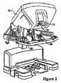
図2は、外科医用コンソール16の斜視図である。外科医用コンソール16は、外科医18に奥行き知覚を可能にする手術野の調整された立体視を提示するための左目ディスプレイ32及び右目ディスプレイ34を含む。コンソール16はさらに、1又は複数の入力制御デバイス36を含み、この入力制御デバイス36は患者側カート22(図1に示される)に1又は複数のツールを操作させる。入力制御デバイス36は、外科医にテレプレゼンスを、又は外科医がツール26を直接的に制御しているという強い感覚を持つように、入力制御デバイス36がツール26と一体であるという知覚を提供するように、それらに関連付けられたツール26(図1に示される)と同じ自由度を提供することができる。この目的を達成するために、位置、力、及び触覚フィードバックセンサ(図示せず)が、ツール26から入力制御デバイス36を通じてまた外科医の手に戻って位置、力、及び触覚の感覚を伝達するために用いられ得る。 FIG. 2 is a perspective view of the
外科医用コンソール16は通常、外科医が、手術を直接監視し得る、必要に応じて物理的に存在し得る、及び電話又は他の通信媒体を通してというよりむしろ助手に直接話し得るように、患者と同じ部屋に位置している。しかし、外科医は、異なる部屋、完全に異なる建物、又は遠隔手術を許している患者からの他の離れた場所にいることができる。 The
図3は、電子装置カート24の斜視図である。電子装置カート24は、内視鏡28に結合されることができるとともに、外科医用コンソールの外科医に、或いは局所的に及び/又は遠隔に配置されたディスプレイに等、その後の表示のために取得された画像を処理するためのプロセッサを含むことができる。例えば、立体内視鏡が使用される場合、電子装置カート24は、外科医に手術野の調整された立体画像を提示するように取得された画像を処理することができる。このような調整は、対照させる画像の間のアライメントを含むことができるとともに、立体視内視鏡の立体作動距離を調整することを含む。他の例として、画像処理は、光学収差等、画像取得装置の結像誤差を補償するために以前に決定されたカメラ較正パラメータの使用を含むことができる。 FIG. 3 is a perspective view of the
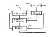
図4は、ロボット手術システム50(図1のMIRSシステム10等)を図式的に示す。上述のように、外科医用コンソール52(図1の外科医用コンソール16等)は、低侵襲性手術中、患者側カート(手術ロボット)54(図1の患者側カート22等)を制御するために外科医によって使用されることができる。患者側カート54は、手術野の画像を取得するとともに取得された画像を電子装置カート56(図1の電子装置カート24等)に出力するために、立体内視鏡等、撮像デバイスを使用することができる。上述のように、電子装置カート56は、任意の後続の表示前に、種々の方法で取得された画像を処理することができる。例えば、電子装置カート56は、外科医用コンソール52を介して組み合わせた画像を外科医に表示する前に、取得された画像を仮想制御インターフェースと重ね合わせることができる。患者側カート54は、電子装置カート56の外部での処理のために取得された画像を出力することができる。例えば、患者側カート54は、プロセッサ58に取得された画像を出力することができ、このプロセッサ58は取得された画像を処理するために使用することができる。画像はまた、電子装置カート56及びプロセッサ58との組み合わせによって処理されることができ、この電子装置カート56及びプロセッサ58は、取得された画像を、一緒に、連続して、及び/又はそれらの組み合わせで、処理するために一緒に結合されることができる。1又は複数の別個のディスプレイ60もまた、手術野の画像、又は他の関連画像等の画像の局所及び/又は遠隔表示のために、プロセッサ58及び/又は電子装置カート56と結合されることができる。 FIG. 4 schematically shows a robotic surgical system 50 (such as the
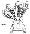
図5は患者側カート22を示す。図示された患者側カート22は、3つの手術ツール26、及び手術野の画像の取得のために使用される立体内視鏡等の撮像デバイス28の操作を提供する。操作は、幾つかのロボット関節を有するロボット機構によって提供される。撮像デバイス28及び手術ツール26は、運動学的遠隔中心が、切開部のサイズを最小化するために切開部で維持されるように、患者の切開部を通って又は患者の開口部を通って、位置決めされるとともに操作されることができる。手術野の画像は、手術ツール26が撮像デバイス28の視野内に位置するときに、手術ツール26の遠位端の画像を含むことができる。 FIG. 5 shows the
図1−5はマルチポート手術ロボットを示す。本発明の実施形態はシングルポート手術ロボットとともに利用されることもできることが理解されるべきである。マルチ又はシングルポート手術のどちらにおいても、手術ツール26は、手術野において患者12に挿入されたカニューレを通される。手術ツール26は、外科医が外科医コンソール16から処置を命令し且つ見ている間に、患者側カート22を通じて操作される。プロセッサ58及び電子装置カート24は、外科医コンソール16の外科医からの入力を手術ツール26のエンドエフェクタの実際の動作に変換するために利用されることができる。典型的に利用され得る手術ツールは、クランプ、把持装置、鋏み、ステープラ、焼灼ツール、リニアカッタ、持針器、又は他の器具を含む。手術ツール26のそれぞれは、患者側カート22に取り付けられ、プロセッサ58及び電子装置カート56によって提供されるように、外科医18の指示の下で患者側カート22によって駆動される。プロセッサ58及び電子装置カート56は、外科医18からの入力を手術ツール26のエンドエフェクタの動作に影響を及ぼす駆動動作に変換する。特に、手術ツール26は、本発明にしたがってステープラ又は血管シーラの一方を含むことができる。 1-5 shows a multi-port surgical robot. It should be understood that embodiments of the present invention can also be utilized with single port surgical robots. In either multi-port or single-port surgery, the
クランプ器具
手術システム10で用いられることができる手術ツール26は、ステープラ及び電気血管シーラのようなクランプ器具を含むことができる。このような装置は、例えば消化管から、癌性の又は異常な組織を切除するために使用されることができる。図6Aは、ステープラ600の例を示す。ステープラ600は、ステープラエンドエフェクタ602、手首部604、器具シャフト606及びシャシ608を含む。Clamping
図6Aに示されるように、ステープラエンドエフェクタ602は、アンビル(anvil)610及びジョー(jaw)612を含む。ステープラカートリッジ614が、ジョー612の上に挿入されることができる。ステープラ600の幾つかの実施形態では、切断ナイフブレード616が、アンビル610の長手方向に沿って移動することができるように、構成される。しかし、操作中、ステープラジョー612は、ジョー612とアンビル610との間に組織をクランプするようにアンビル610に押し付けられるので、ステープラ600は、把持装置として用いられることができる。 As shown in FIG. 6A, the
適切な組織の隙間、クランプ中のジョー612とアンビル610との間の距離は、適切なステープル形成のために重要である。組織の隙間が大き過ぎる場合、ステープルは発射中に適切に形成しない。大きい組織の隙間は、ジョー612とアンビル610との間に過度に厚い材料をクランプすることによってもたらされることができる。幾つかの場合には、ステープルエンドエフェクタ602は、所定のクランプ位置に駆動されることができ、この位置を達成するために必要とされるトルクが測定されることができる。トルクが高過ぎる場合、アンビル610は曲がり、組織の隙間はあまりに大きくなる。幾つかの実施形態では、制限トルク(トルク限度)が設定されることができ、エンドエフェクタ602は、所定のクランプ位置に向かって動かされることができる。制限トルクがエンドエフェクタ602に所定のクランプを達成させることを防ぐ場合、適切な組織の隙間は達成されることができない。どちらの場合も、アンビル610に作用するトルクの正確な検知又は制御が、不適切な組織の隙間を正確に検出するために重要である。
Proper tissue clearance, the distance between
ステープラが発射されるとき、ステープルは、介在組織を通り、ジョー612に沿って移動するスレッド(sled)618によってアンビル610の中に押し込まれる。組織の隙間である、ジョー612とアンビル610との間の距離は、ステープルの適切な形成を決定する。組織の隙間を制御することは、適切なステープル形成を確実にするのに役立つことができる。ジョー612とアンビル610との間の適切なクランプ力は、ステープル形成のための適切な組織の隙間を提供する。組織への適切なクランプ力は、カートリッジ614の機能であり、このカートリッジは、ステープルの長さを決定する。 As the stapler is fired, the staples are pushed into the
加えて、(I形梁のように形成され得る又はスレッド618に取り付けられ得る)ナイフブレード616は、ステープル留めされた組織を切り離すためにアンビル610に沿って並進移動される。幾つかの実施形態では、スレッド618及びナイフブレード618は、カートリッジ614の中に形成される。組織の隙間が正しくない場合、ステープルは不適切に形成される可能性があり、組織の損傷及び他の合併症を引き起こす。幾つかの実施形態では、ステープラ600は、リニアステープラであり得る。幾つかの実施形態は、ナイフブレード616を含まなくてもよく、したがって、切断なしでステープル留めを実行する。 In addition, knife blade 616 (which can be formed like an I-beam or attached to thread 618) is translated along
止血及び空気漏れ防止(ステープル留め装置を使用する組織のシール)の達成は、ステープルが出血及び漏れを防ぐために適切に組織を圧迫するように、発射後に、組織にクランプ力に起因する適切な圧力を提供することに依存する。大き過ぎる圧力を提供することは、ステープルが組織を血液供給を完全に遮断するのに十分きつく圧搾することをもたらす場合があり、組織が治ることを阻み、壊死につながる。 Achieving hemostasis and air leak prevention (tissue sealing using a stapling device) is the result of proper pressure due to the clamping force on the tissue after firing so that the staples properly compress the tissue to prevent bleeding and leakage. Depends on providing. Providing too much pressure may result in the staples squeezing the tissue tight enough to completely shut off the blood supply, preventing the tissue from healing and leading to necrosis.
上述のように、大き過ぎるクランプ力が、エンドエフェクタ602を所定のクランプ位置に位置決めするために使用される場合、アンビル610及びジョー612の先端の間のたわみは、不正確なクランプをもたらし得る。さらに、小さすぎるクランプ力では、ジョー612は、アンビル610に対して所定のクランプ位置へ完全に閉じない場合があり、この場合もやはり組織の不適切なステープル留めをもたらす。 As described above, if too much clamping force is used to position the
ステープラカートリッジ614は、組織の厚さを含む、特定の状況のために、色分けされることができる。幾つかの異なる色が利用されることができるが、色分けの以下の表が適用し得る:
The

カートリッジ614は、様々な長さ、例えば、30、45、又は60mmであり得る。単一のステープラ600は、1回発射されるそれぞれのカートリッジを伴って、多くの再装填を発射することができる。カートリッジ614は、例えば、カートリッジシリアルナンバ、カートリッジタイプ、部品番号、スタイル、発射の方向、発射の長さ、カートリッジの色、発射トルク、最大たわみ及び他のデータを保持するデータストレージを含み得る。幾つかの実施形態では、ナイフブレード616及びスレッド618は、カートリッジ614の一部であり、各再装填で入れ替えられる。
The
図6Bは、組織650にクランプされたステープルエンドエフェクタ602を示す。図6Bに示されるように、カートリッジ614は、ステープル562を含む。発射中、スレッド618は、カートリッジ614に収容されているステープル652をクランプされた組織を通ってそしてアンビル610のポケット654の中に駆動するために、ジョー612に沿って移動することができる。ポケット654は、ステープルを“B”形状に形成するように構成され、この“B”形状は最適なシールを提供する。図6Bは、ステープル652のそれぞれの脚が個々のポケット654によって“B”形状の一部に形成されることができる実施形態を示しているが、幾つかの実施形態では、ステープル652は単一のポケット654によって形成されることができる。ナイフ616は、ステープル留めされた組織を切断するために、ステープルの列の間の組織を切断する。カートリッジ614は、幾つかのステープルの列を作ることができ、例えば、ナイフ616によって形成される切断部のそれぞれの側部の2又は3列が形成され得る。 FIG. 6B shows
ジョー612及びアンビル610のクランプ動作並びにスレッド618及びナイフ616の発射動作は、外部モータ(図6Aに示されない)からのトルクをカプラ660に結合するシャシ608によって、駆動される。カプラ660は、例えば駆動シャフト又はケーブルであることができる。カプラ660は、シャフト606に沿って移動し、エンドエフェクタ660及びカートリッジ614のカム、ギア、ねじ、又はウォーム駆動部に結合する。カプラ660はまた、手首部604を制御するために利用される。図6Aに示されるように、シャシ608は、器具シャフト606を通ってエンドエフェクタ602に延びるケーブルの張力又はシャフトの回転を制御することによってカプラ660を制御する。アンビル610に対するジョー612のクランプは、ジョー612をアンビル610に回転させる或いはアンビル610をジョー612に回転させるカム機構で管理されることができる。スレッド618及びナイフ616の発射は、例えば、駆動シャフトカプラ660によって駆動されるリードネジ機構によって駆動されることができる。幾つかの実施形態では、ジョー612及びアンビル610のクランプ並びにスレッド618及びナイフ616の発射は、剛性シャフトによって制御されることができる一方、ジョー612及びアンビル610の通常の把持並びに手首部604のピッチ及びヨーはケーブルによって制御されることができる。幾つかの実施形態では、クランプ及び発射は、ケーブルによって制御され得る。 The clamping action of the
ステープラ600の発射中の適切なクランプを提供するために、特定のクランプ力がジョー612とアンビル610との間に提供される。そのクランプ力は、シャシ608に結合されたモータのトルクによって初めに提供される。クランプ力を提供するための適切なトルクは、シャシ608の製造上のばらつき並びに、例えば、シャフト606、手首部604、並びにジョー612及びアンビル610の機械的動作に存在し得る摩擦に起因して、ステープラごとに変化し得る。さらに、ステープラ600は摩耗するので、適切なクランプ入力トルクは、ステープラ600の寿命の間にドリフトし得るとともに、それは、ジョー612とアンビル610との間の適切なクランプ力に作用するためにシャシ608に加えられるより少ないトルクを取り得る。不適切なクランプ力は、ジョー612及びアンビル610の不適切なたわみのために不適切な組織の隙間をもたらすので、大き過ぎるトルクがシャシ608に加えられる又は小さすぎるクランプ力を通じてジョー612及びアンビル610の不適切な閉じがある場合、ステープル652の不適切な形成が発射中に生じ得る。このような不適切なクランプはまた、不適切なステープル形成及びプロセスの間の不適切なクランプの両方の結果として、組織650を傷つけ得る。 A specific clamping force is provided between the
上述のように、アンビル610に対してジョー612をクランプするための共通の駆動機構は、カム機構の利用を伴う。しかし、不適切なクランプは、単にカムの位置だけによって決定されることができない。これは、ジョー612及びアンビル610の可撓性の結果であり、これは、ジョー612及びアンビル610の先端の付加的な分離をもたらし得る。大き過ぎるクランプトルクが加えられるとき、ジョー612とアンビル610との間の先端分離、組織の隙間、は大きくなり過ぎ得、発射中の不適切なステープル形成をもたらす。したがって、本発明の幾つかの実施形態では、制限トルクが設定され、且つ、過度な先端分離(組織の隙間)がクランプ中に妨げられるように、ステープラ600に適用される。発射は、制限トルクが実行されながらステープラ600が完全にクランプされた位置に達することができる場合にのみ許可される。制限トルクがクランプを妨げる(止める)場合、組織は十分圧迫されることができず、クランプが進行することになっている場合、ジョー612及びアンビル610の可撓性に起因する過度な先端分離が起こるであろう。ステープラ600は、したがって、ジョー612及びアンビル610が完全な行程に達し(すなわち、リードネジ又はカルダン(cardan)の予想された数の回転が達成されることによって)且つ制限トルクに達していないときにクランプされるとみなされることができる。 As described above, a common drive mechanism for clamping the
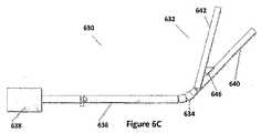
同様の問題が血管シーラで生じる。図6Cは、血管シーラ630を示す。血管シーラ630は、エンドエフェクタ632、手首部634、器具シャフト636及びシャシ638を含む。エンドエフェクタ632は、ジョー642及び640を含み、これらのジョーはシールされることになる組織の上をクランプする。ステープルの代わりに、血管シーラ630は、ジョー640と642との間にクランプされた組織をシールするRF法を利用することができる。 Similar problems occur with vascular sealers. FIG. 6C shows a
図6Dは、ジョー650を持つエンドエフェクタ632を示し、このジョーはジョー640又は642のいずれかであることができる。図6Dに示されるように、ジョー650は、ジョーケース652に埋め込まれた電極654を含む。ナイフ646は、電極654に形成されたトラック658に沿って駆動されることができる。ジョーケース652は、電極654の間の最小ギャップがプロセス中に維持されるように、電極654を超えそして上に拡がる先端656を有する。幾つかの実施形態では、最小ギャップは、例えば、0.006インチであることができる。発射されるとき、ジョー640及び642は、組織をシールするためにエネルギを与えられることができ、ナイフブレード646は、組織を分割するためにジョー640及び642のトラック658に沿って移動することができる。エネルギは、ジョー640及びアンビル642の電極654を通じて供給される。幾つかの実施形態では、ナイフブレード646は、シールエネルギから独立して作動されることができる。 FIG. 6D shows an
適切なクランプ力が、電気焼灼術の間の適切なシール形成のために提供されることが必要とされる。過度なクランプ力は、駆動機構、例えば、リードネジ機構に損傷を与え得る。したがって、血管シーラ630の動作は、十分なクランプ力をジョー640及び642に提供する一方血管シーラ630それ自身に損傷を与えないことに依存する。力の上限は、1)血管シーラ630に損傷を与えないこと及び2)安定した性能を提供することの目標に基づいている。 Appropriate clamping force is required to be provided for proper seal formation during electrocautery. Excessive clamping force can damage drive mechanisms, such as lead screw mechanisms. Accordingly, the operation of
本開示は、ステープラ600の動作に注目しているが、当業者は、血管シーラ630のような他の器具もまた利益を得ることができることを認識するであろう。ステープラ600又は血管シーラ630のいずれにおいても、エンドエフェクタの様々な動作はシャシを通じて器具シャフトを通って延びるケーブルによって制御される。シャシは器具シャフトのカプラに作用するために駆動され、このカプラはエンドエフェクタにおける動作を制御する。ステープラ600に関して上述されたように、クランプ及び発射を制御するカプラは、駆動シャフト、ケーブル、プッシュプルロッド、又は他の機構であることができる。シャシを駆動するために利用されるモータのトルクは、エンドエフェクタの様々な構成要素に加えられる力に変わる。 Although the present disclosure focuses on the operation of the
図7は、モータ組立体702に取り付けられた手術用ステープラ600を示す。モータ組立体702は、ステープラ器具に取り付けられることができ、このステープラ器具は患者側カート22の手術用アームに取り付けられる。モータ組立体702はまた、患者側カート22の手術用アームの1つに取り付けられることができる、又は患者側カート22の手術用アームの1つの一部にされることができる。図7に示されるように、モータ組立体702は、機械的カプラ706を通じて機械的に結合される1又は複数のモータ710及び電子装置712を含む。機械的カプラ706は、ステープラ600がモータ組立体702に取り付けられるとき、シャシ608に結合されることができる。幾つかの実施形態では、1又は複数のモータ710は、クランプモータ及び発射モータを含み得る。1又は複数のモータ710及びモータ組立体702の電子装置712の組み合わせは、モータパックと称されることができる。手首部604を駆動するモータは、モータ組立体702に含まれ得る又はモータ組立体702から分離され得る。機械的カプラ706は、1又は複数のモータ710からのトルクをシャシ608に伝達し、ここでトルクは機械的コンバータ714によってケーブル660に伝達される。 FIG. 7 shows the
電子装置708は、データを格納し、データをモータ組立体702に伝達するために、記憶用メモリ及びインタフェース電子装置を含む。電子装置708に格納されるデータは、手術用ステープラ600に関連するパラメータを含む。このようなデータは、ステープラ600を識別し且つ制御するために利用されることができ、例えば、シリアルナンバ、器具タイプ、寿命(すなわち、発射回数)、及びステープラ600に関する他の情報を含み得る。電子装置708に器具データを格納することは、例えば、米国特許第6,866,671号に記載されており、これはその全体が参照により本願に援用される。 The
電子装置708はまた、カートリッジ614がエンドエフェクタ602の中に配置されるとき、カートリッジ614のデータストレージ716と通信することができる。データストレージ716は、例えば、そのID、カートリッジロット番号、カートリッジタイプ、カートリッジシリアルナンバ、カートリッジ発射状態、カートリッジの色、長さ、トルクオフセット、及び他のデータを含む、カートリッジに関連するデータを格納することができる。カートリッジ614のデータストレージ716に格納されたデータは、どのようにステープラ600、カートリッジ614、及びモータ組立体702が一緒に利用されることになるかを決定するために制御システムに伝達されることができる。 The
モータ組立体702は、インタフェース704を通じて電子装置708とデータを交換する電子装置712を含むことができ、そのデータ及び他の情報を患者側カート54を通じてシステム10の他のコンポーネントと通信し、システム10の他のコンポーネントからデータ及び指示を受信する。電子装置712はまた、モータ組立体702に関連するデータ、例えば、モータ組立体タイプ、シリアルナンバ、寿命(すなわち、発射寿命回数)、及びモータ組立体702の動作に関する他の情報を格納することができる。電子装置712はまた、ステープラ600に機械的に結合される1又は複数のモータ710への入力を提供することができ、並びにモータ又は機構の他の構成要素の位置を監視するセンサからのデータを受信する。このような入力は、1又は複数のモータ710に提供される電流を制御及び制限するためであり得るとともに、1又は複数の電流ループ制御回路及び/又は位置ループ制御回路を含み得る。 The
図8は、ステープラ600を持つ手術システムの動作を示すが、血管シーラのような他のクランプ器具が利用され得る。図8に示されるように、シャシ608の電子装置708は、メモリ808及び電子装置806を含む。メモリ808は、ステープラ600に関するパラメータを格納することができる不揮発性メモリを含む。上述のように、このようなパラメータは、ステープラ600の動作パラメータ、ステープラ600の寿命、ステープラ600のタイプ、及び他のパラメータを含み得る。電子装置806はまた、カートリッジ614からデータストレージ716を読み取り且つこれらのパラメータを中継するように結合される。電子装置806は、インタフェース704を通じて受信される信号に応じて、メモリ808からパラメータを及びデータストレージ716からパラメータを読み取ることができる。 FIG. 8 illustrates the operation of the surgical system with
幾つかの実施形態では、インタフェース704は、シャシ608とモータ組立体702との間の電気的な接続部を含む。電子装置806は、プロセッサ及びメモリ88からデータを読み取り且つメモリ808にデータを書き込む他の電子装置を含むことができる。 In some embodiments,
モータ組立体702の電子装置712は、電子装置810及びメモリ812を含む。電子装置810は、インタフェース704を通じて電子装置806とインタフェース接続するプロセッサ又は他の電子装置であることができる。図8に示されるように、電子装置810はまた、1又は複数のモータ710に制御信号を提供する。図8はモータ802及び804を示す。モータ802及び804は、ステープラ602の機能が実行されるように機械的コンバータ714を駆動する。 The
特に、モータ804は、クランプモータであり、組織650に対するジョー612とアンビル610との間のクランプを提供するようにステープラ600を動作させる。モータ802は、発射モータであり、ステープラ600を発射させるようにステープラ600及びカートリッジ614を動作させる。ステープラ600は、ステープラ600がクランプされるとき発射される。クランプされる条件は、モータ804の出力位置が適切なクランプ位置に達する一方同時に制限トルクが過度な先端分離を防ぐために実装されるときに決定されることができる。モータ804によって供給されるトルクは、モータ804に供給される電流によって制御されることができる。モータ804に供給される電流は、電子装置810によって制御されることができる。動作において、制限トルクが、器具及びともに使用されるモータ組立体(又はモータパック)に基づいてモータ804に対して提供される。クランプは、モータ804の適切な位置が達成される一方適切な制限トルクが実装されるとき、決定されることができる。制限トルクは、モータ804に対する制限電流(電流限度)に直接関連し、したがって、モータ804の電流引き込みが対応する制限電流に達するとき、制限トルクに到達する。In particular,
電子装置810は、メモリ812に格納された指示を実行するプロセッサ及び電子装置を含み得る。このようなものとして、電子装置810は、モータ804を制御するために電流コントローラ及び位置コントローラを含むことができ、これらのモータは、それぞれクランプモータ804及び発射モータ802であることができる。図8にさらに示されるように、電子装置810は、モータ組立体702のパフォーマンスを監視する様々なセンサ820を含むことができる。センサ820は、例えば、モータ組立体温度を測定するための温度センサ、少なくとも1つのモータ710のそれぞれによって引き込まれる電流を測定するための電流センサ、及び少なくとも1つのモータ710のそれぞれの出力位置を測定するための位置センサを含むことができる。
メモリ812は、揮発性及び非揮発性メモリの組み合わせを含み得るとともに、1又は複数のモータ710を制御するためのデータ及び実行可能な指示を格納し得る。メモリ812は、モータ組立体702に関連するパラメータを含むことができ、シリアルナンバ、部品番号、バージョン番号、構成情報(タイプ、スタイル、有効期限情報、電流コントローラゲイン、位置コントローラゲイン、ギア比)、温度係数、摩耗係数、摩擦係数、モータKT(トルクを電流と関連付けるパラメータ)及び他の情報を含む。
ステープラ600の他の機能、例えば、手首部604の動作並びに発射中のスレッド618及びナイフ616の並進移動は、他のモータ又は機械的コンバータ714を用いて動作するモータの組み合わせによって提供されることができる。理解されるように、機械的コンバータ714は、適切な動作を提供するようにケーブル660に結合されるギア及びカムの組み合わせであることができる。発射モータ802又は他の駆動モータのような、他のモータへの電流もまた、電子装置810によって制御されることができる。 Other functions of the
電子装置810はさらに、指示を受信し且つデータを提供するようにシステム800に結合される。システム800は、図4の外科医コンソール52、電子装置カート56、プロセッサ58、及びシステム50のディスプレイ60の組み合わせを表すことができる。このようなものとして、システム800は、1又は複数のプロセッサ802、メモリ804、データストレージ814、及びユーザインタフェース816を含む。ユーザインタフェース816は、外科医コンソール52、ディスプレイ60、キーボード、タッチスクリーン、又は他の適切な入力デバイスであることができる。ストレージ814は、フラッシュメモリ、ハードドライブ、CDリーダ若しくは他の記憶媒体のリーダ、又はデータを格納するための他の装置のような、任意のデータストレージシステムであることができる。メモリ804は、データ及び処理ステップの格納のための揮発性及び非揮発性メモリを含むことができる。幾つかの場合では、メモリ804は、ストレージ814から、プログラミングステップを含む、データをロードされることができる。 The
幾つかの実施形態では、電子装置810及び電子装置806は、整数演算をサポートし得る。電子装置810及び電子装置806で動作するアルゴリズムは、モータ804及び802を制御しながらそれらに割り当てられる数学演算を実行するために、適切に調整されることができる。 In some embodiments,
動作において、ステープラ600の動作に関するパラメータは、メモリ808から読み込まれ且つ電子装置810及びプロセッサ802に提供される。外科医の入力はユーザインタフェース816で受信される。プロセッサ802は、入力をステープラ600の動作のための指示に変換するように指示を実行し且つ電子装置810に指示を提供する。幾つかの実施形態では、メモリ808から読み込まれるパラメータは、電子装置810に提供される指示を決定するのに利用されることができる。電子装置810は、プロセッサ802によって示される動作を提供するために1又は複数のモータ710に信号を提供する。これらの動作はその後、エンドエフェクタ602に伝えられる。1又は複数のモータ710に提供される信号はまた、メモリ808から読み込まれるパラメータに基づき得る。幾つかの場合、プロセッサ802は、ステープラ600の次の利用の間に利用されることになるメモリ808のパラメータを提供し得る又は書き換え得る。 In operation, parameters relating to the operation of
一般的に、モータ組立体(又はモータパック)、ステープラ、及びカートリッジは調和がとられていない。処置中、任意のモータ組立体が任意のステープラとともに利用されることができ、任意の様々なカートリッジがそのステープラで利用されることができる。したがって、データストレージ716は、ステープラカートリッジ614に関連付けられるパラメータを保持し、メモリ808は、その特定のステープラ600に関連付けられるパラメータを格納し、メモリ812は、その特定のモータ組立体702に関連付けられるパラメータを格納する。 In general, the motor assembly (or motor pack), stapler, and cartridge are not harmonized. During the procedure, any motor assembly can be utilized with any stapler, and any of a variety of cartridges can be utilized with the stapler. Thus,
ステープラの初期化
上述のように、(再装填とも称される)ステープルカートリッジは、色によって識別される様々なサイズが利用可能である。それぞれの色のカートリッジは、特定のステープル脚長さに対応する。一般的なカートリッジは、緑(4.3mm脚長さ)、青(2.5mm脚長さ)、及び白(1.5mm脚長さ)カートリッジ614を含む。ステープルを適切に形成するために、アンビル610及びジョー612は、ステープル652がアンビル610のポケット654に衝突し且つ所望の“B”形状(図6B)を形成することを確実にするように、極めて近接した範囲内に位置決めされる必要がある。ステープラ600は、「片持ち梁」スタイルのクランプを利用し、上述のように、制限クランプトルクが高過ぎる場合、アンビル610及びジョー612の先端は、互いに離れて、発射プロセスの間にステープル652がカートリッジ614から押し出されるときステープル652が適切に形成しないポイントにたわむことが可能である。この状態は、高過ぎるトルクでのクランプの間にジョーの中に多過ぎる組織がある場合、現れ得る。これを防ぎ且つ適切な先端の隙間が維持されることを確実にするために、クランプトルクは制限される。Stapler Initialization As noted above, staple cartridges (also referred to as reloading) are available in various sizes, identified by color. Each color cartridge corresponds to a particular staple leg length. Typical cartridges include green (4.3 mm leg length), blue (2.5 mm leg length), and white (1.5 mm leg length)
理想的な状況下では、ステープラ600のそれぞれが同一である場合、全てのステープラ600は同じ制限トルクを使用するであろう。しかし、製造上のばらつき及び公差は、異なるステープラ600の間にかなりのばらつきをもたらし得る。本発明によれば、制限トルクは、ステープラ600のそれぞれに対してカスタマイズされることができる。結果として、メモリ808は、特定のステープラ600に関連付けられる特定の制限トルクを格納することができる。さらに、制限トルクは、カートリッジ614にしたがって個別のステープラ600の中で変化することができる。したがって、カートリッジ614のタイプに関する調整もまたメモリ808の中に格納されることができる。幾つかの実施形態では、カートリッジ614のタイプに関する調整は、ステープラ600の間で変化しない場合があり、したがって、設定されたカートリッジ変動値がシステム800によって提供されることができる又は各カートリッジ614のデータストレージ716に格納されることができる。幾つかの実施形態では、カートリッジ614のタイプに関する調整は、ステープラ600の間で変化しない場合があり、したがって、設定されたカートリッジ変動値はシステム800によって提供されることができる又は各カートリッジ614のデータストレージ716に格納されることができる。製造中、各ステープラ600は、組み立てられ、そしてその後クランプ挙動に馴染ませるように操作される。 Under ideal circumstances, if each of the
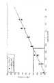
本発明によれば、特定の制限トルクが各ステープラ600に対して決定されそしてシャシ608のメモリ808に格納される。図9Aは、特定のステープラ600に対する制限トルクを初期化するための手順を示す。ステップ902では、ステープラ902が組み立てられる。組立後、ステップ904では、ステープラ600は、クランプ行動を繰り返し実行することによって「馴染ませられる」。クランプするために必要なトルクが、比較的安定している(すなわち、活動の間に著しく変化しない)とき、ステープラ600は馴染んでいる。ステップ906では、異なる高さの一連のシムが、クランプ中にジョー612及びアンビル610の先端に既知のたわみを強制するために利用される。先端のたわみに応じたクランプトルクのデータセットがその結果得られる。 In accordance with the present invention, a specific torque limit is determined for each
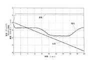
図9Bは、シム914を用いて既知の量で先端をたわませることを示す。図9Bに示されるように、シム914は、ジョー612及びアンビル610がクランプされる間に、特定の先端分離を強いる。ステップ906において、異なるシム914を用いる一連のテストが、図9Cに示されるデータセットを作るために遂行される。図9Cに示されるように、X軸は各個別のシム914によって強いられるたわみを示す。Y軸は、クランプ条件を実現するためにテスト中にステープラ602のシャシ608を駆動するモータ組立体916のモータ918からの記録されたトルクデータである。幾つかの実施形態では、モータ918のフィードバック電流とモータ918によって加えられるトルクとの間の関係及びジョー612とアンビル610との間の結果として生じる力は、モータ918及び多数の器具を利用して事前に取得された較正データに基づいて知られている。 FIG. 9B shows the
ステップ908では、データは関数にあてはめられることができる。図9Cに示された例では、データは線形関数Y=mX+bにあてはめられる。線形最小二乗法が、傾きm及びオフセットbを推定するために用いられることができる。この線形方程式では、Yは必要トルクでありXは先端たわみである。図9Cに示されるように、トルクはミリニュートンメートル(mNm)で提供され、たわみはミリメートル(mm)で提供される。図9Cに提供される特定の例では、傾きmは12.5mNm/mmであることが決定されオフセットbは50mNmである。上述のように、m及びbに関する値は、異なるステープラの間の製造のばらつきに起因して変化する。 In
ステップ910では、最大トルク値がステープラ600に対して決定される。幾つかの実施形態では、最大トルクは、最大先端たわみを0.7mmに制限することによって決定される。0.7mmは、青色カートリッジ614に対して適切である先端分離であり、これは、青色カートリッジに対して安全基準を確立すると見なされることができる。この例示の値は、先端分離に起因する発射中のステープルの不適切な形成を防ぐ。図9Cから見ることができる、又は上述の線形関係によって計算されることができるように、図9Cに示される特定のステープラ600は、65mNmの最大トルク値を有する。これを超えるトルク値は、適切なステープル形成に対する過大な先端たわみ(したがって過剰な大きさの組織隙間)を可能にし得る。制限トルクを強制することによって、十分なトルクがクランプのために供給されるが、過大なトルクは許可されず、これは不適切なステープル形成をもたらすより大きい先端たわみを防ぐ。 In
ステップ912では、ステープラ600に対する最大トルク値がステープラ600のシャシ608のメモリ808に格納される。最大トルク値はその結果、図8に示されるように、システム10の動作中にメモリ808から読み込まれることができ、ステープル留め処置の間にモータ804によってエンドエフェクタ602に供給される最大トルクを制御するために利用されることができる。 In
幾つかの実施形態では、τcalとして示されることができる較正された最大トルク値が、ステープラ600に対する基準制限トルク値として使用される。この基準から、操作中、実際のトルクが特定のカートリッジ614に対して調整されることができる。調整値は、システム800の中にロードされる多数のカートリッジ及び多数のステープラを利用して取得された大規模な事前に収集される実験的及び分析的データに基づき得る。例として、様々なカートリッジ614に対する調整値は、白=−3mNm、青=+2mNm、及び緑=+9mNmであることができる。これらの値は、最大トルク値及びモータ組立体702のモータのトルク出力を制御するために利用される調整された値に加えられる。例えば、カートリッジ614が青色カートリッジである場合、クランプの間に利用される最大トルク値は94mNmに調整される。In some embodiments, a calibrated maximum torque value that can be denoted as τcal is used as a reference limit torque value for the
上述の説明で利用される実際の数字は、説明のためだけのものであり、限定するものと見なされるべきではない。ステープラ600のそれぞれは、異なる最大トルク値を有し得る。加えて、幾つかの実施形態では、異なる安全先端たわみ又は他のパラメータが利用されることができる。さらに、カートリッジのタイプに対する調整値は変化し得る。また、上述の議論はステープラ器具に着目しているが、同様の較正が、他の器具、例えば血管シーラに実行されることができる。 The actual numbers utilized in the above description are for illustration only and should not be considered limiting. Each of the
他のパラメータもまた較正中に設定されることができる。例えば、較正された制限トルクは、測定の基準温度Trefにおいて設定されることができる。他のパラメータは、摩耗係数、器具寿命係数、及び特定のステープラ600に関連する他のパラメータを含み得る。Other parameters can also be set during calibration. For example, a calibrated limit torque can be set at the measurement reference temperature Tref . Other parameters may include wear factors, instrument life factors, and other parameters associated with a
各器具に対して最大制限トルクを調整及び較正することは、クランプ中の先端たわみのより正確な制御を可能にする。これは、器具性能を最大化することができる。各器具を較正することによって、単一の一定パラメータが全ての器具に渡って一様使用される場合より小さいマージンが利用されることができる。加えて、クランプ中の先端たわみの不確かさが、より正確にクランプを制御することによって、減少されることができる。さらに、製造公差への依存を減少させること及び且つ製造のばらつきを調整することによって、製造歩留まりが増加されることができる。 Adjusting and calibrating the maximum limiting torque for each instrument allows for more precise control of tip deflection during clamping. This can maximize instrument performance. By calibrating each instrument, a smaller margin can be utilized if a single constant parameter is used uniformly across all instruments. In addition, tip deflection uncertainties during clamping can be reduced by more accurately controlling the clamp. In addition, manufacturing yield can be increased by reducing dependence on manufacturing tolerances and adjusting manufacturing variability.
モータ組立体のモータの初期化
ステープラ600を較正すること及び初期化することに加えて、モータ組立体702もまた、製造上のばらつきを調整するために較正及び初期化されることができる。クランプモータ804及び発射モータ802並びに機械的コンバータ714の製造上のばらつきは、モータ組立体の間のばらつきをもたらす。モータ組立体の較正の間、クランプモータ804及び発射モータ802のそれぞれに対するモータ速度対無負荷電流の関係INL及びトルク定数KTが決定される。Initializing the Motor of the Motor Assembly In addition to calibrating and initializing the
図10Aは、モータ組立体702のモータ804及び802のそれぞれを較正するために利用されることができる較正方法1000を示す。方法1000に示されるように、ステップ1002は、組み立てられたモータ組立体702を取得することである。ステップ1004では、初期較正が実行される。較正手順の例は図10Bに示される。ステップ1006では、モータ組立体702のモータ802及び804が馴染ませられる。馴染ませ工程中、モータ802及び804のそれぞれは、機械的コンバータ714のギアトレインを馴染ませるために及びグリースが均等に分散されるように、一定のトルクに対抗して多くのサイクルを駆動される。ステップ1008では、最終的な較正が実行される。ステップ1008の最終的な較正及びステップ1004の初期較正は、同じ較正方法であることができ、この例は図10Bに示される。ステップ1010では、較正されたパラメータがモータ組立体702のメモリ812に格納される。 FIG. 10A shows a
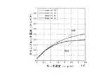
図10Bは、図10Aのステップ1004及び1008で利用されることができる較正手順の例を示す。図10Bに示されるように、ステップ1014は、モータに対する無負荷データを取得することであり、このモータはクランプモータ804又は発射モータ802のいずれかであり得る。モータに対するモータ速度と無負荷電流との間の関係を決定するために、モータは様々な速度で、1つずつ最初は順方向に次に逆方向に、駆動される。様々な速度のそれぞれを達成しながら、無負荷電流データ、並びにモータ組立体702の温度が測定される。幾つかの場合には、無負荷電流引き込みが温度に対して調整されることができる。例として、毎分104回転(rpm)における速度数列(speed progression)は[2.5、1.5、2.25、0.5、2.0、.75、1.0、1.75、0.25、1.25、及び0.125]であり得る。しかし、数列を取る他のデータが利用されることができる。図10Cは、順(fwd)及び逆(bak)方向のモータ速度に応じたクランプモータ804電流に関するデータを示す。FIG. 10B shows an example of a calibration procedure that can be utilized in
ステップ1016では、データが、モータ電流とモータ速度との間の関係を決定するために、ある関数、例えば、指数関数又は線形関数にあてはめられる。例えば、データをあてはめるために使用されることができる非多項式の項を持つ線形関数は、
In
によって与えられることができ、ここでc1、c2、c3は係数でありxscaleは定数である。
Where c1, c2, c3 are coefficients andxscale is a constant.
図10Cでは、実線は、データへの曲線あてはめを示す。データは、温度に対して調整され得るとともにあてはめに先立ってフィルタにかけられ得る。幾つかの実施形態では、生データが温度に応じたモータの以前のモデリングに基づいて温度応じて調整されることができる。さらに、生データは、ノイズを減少させ且つ平均化を提供するために時間に応じてフィルタにかけられる。 In FIG. 10C, the solid line shows a curve fit to the data. Data can be adjusted for temperature and filtered prior to fitting. In some embodiments, the raw data can be adjusted as a function of temperature based on previous modeling of the motor as a function of temperature. Furthermore, the raw data is filtered according to time to reduce noise and provide averaging.
幾つかの実施形態では、区分線形近似が、さらなる計算を容易にするために関数をあてはめるように最適化されることができる。図10Cに示される曲線あてはめへの区分線形近似は図10Dに示される。区分線形近似は、INLとしてメモリ812に最終的に格納されることができる。In some embodiments, the piecewise linear approximation can be optimized to fit a function to facilitate further calculations. A piecewise linear approximation to the curve fit shown in FIG. 10C is shown in FIG. 10D. The piecewise linear approximation can eventually be stored in
いったん無負荷電流較正が完了すると、手順1012は、トルク定数KT(電流入力毎のトルク出力)の決定に進む。図10Bに示されるように、ステップ1018は、トルク負荷データを取得することを含む。トルク負荷データを取得するステップにおいて、較正されるモータ(クランプモータ804又は発射モータ802)は、最初に無負荷に対して駆動され、次に負荷は既知のトルク負荷まで増やされ、その後無負荷に減らされる。既知のトルク負荷は、例えば、ブレーキ又は動力計のような、外部ソースによって提供されることができる。データ(すなわち、トルク出力対電流負荷)は、較正されているモータに対して順及び逆方向の両方で収集される。複数セットのデータが、クランプモータ804及び発射モータ802のそれぞれに対して取られることができる。Once the no-load current calibration is complete, the
ステップ1020では、トルクデータがトルク定数KTを決定するために分析される。データは、フィルタにかけられることができ、トルク定数KTは、(無負荷から既知のトルク負荷への)トルクの変化を(無負荷での電流からそのトルク負荷での電流への)電流の変化と比較することによって決定されることができる。ステップ1018の間に取られる複数セットのデータに対する計算は、最終的な較正トルク定数値を決定するために平均化されることができる。In
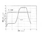
図10Eは、本発明の幾つかの実施形態によるデータ取得ステップ1018の間のモータに関するモータ速度及びトルク対時間の例を示す。図10Fは、図10Eに示されるデータに対応する時間に応じたモータ速度、電流、及びカルダン位置を示す。図10Fに示されるように、電流データは、試験に関する電流対時間の連続関数を得るためにフィルタにかけられることができる。 FIG. 10E illustrates an example of motor speed and torque versus time for a motor during the
図10Aに示されるように、最終的な較正ステップ1008の後のステップ1010では、無負荷電流較正データINL及びトルク負荷較正データKTが、モータ組立体702のメモリ812に格納されることができ、以下にさらに論じられるように、モータ組立体702に対する制限トルクの更なる計算の間に利用されることができる。As shown in FIG. 10A, in
制限トルク補償
図8に戻って参照すると、ステープラ600は、ステープラ600が完全なクランプ状態に達するときにのみ発射することを許される。完全なクランプ状態に達するためにモータ804によって提供されるトルクの量はソフトウェアによって制限される。この制限トルクは、概して、制限電流として設定され、この制限電流は、モータ804がクランプ工程の間に引き込むことが許容される電流の限界である。制限電流は、上述のように、ステープラ600に対する較正データの関数である。言い換えると、最初に制限トルクが上述のようにτcalに設定され、カートリッジ614の色に従って調整される。Limiting Torque Compensation Referring back to FIG. 8,
しかし、ステープラ600の繰り返しの使用のために、有効制限トルクは、ドリフトし且つ元の較正データから逸脱し得る。言い換えると、数回の使用の後にステープラ600をクランプさせるために要する同じトルクは、その初期較正状態でステープラ600をクランプさせるために要したトルクと異なり、典型的には、より小さい。制限トルクが不変のままである場合、ステープラ600は、意図されないチャレンジ材料への完全なクランプ動作に達することが許されるかもしれず、ジョー612とアンビル610との間の先端の意図されない増大したたわみをもたらす。上述のように、増大した先端のたわみは、不適切な組織隙間及びステープラが発射された場合に不適切に形成されるステープルをもたらす。 However, due to repeated use of the
本発明の幾つかの実施形態によれば、ステープラ600に利用される制限トルクは、多数の動作パラメータにしたがって調整される。多数の動作パラメータは、例えば、モータ組立体702の温度、手首部604の関節角度、モータ組立体702の寿命使用量(例えば、モータ組立体702によって作用されるステープラ発射の数)、及びステープラ600の寿命使用量(例えば、ステープラ600を使用するステープラ発射の数)を含む。実際の制限トルクは、ステープラ600の年齢及び動作状態に対して調整するために動作中に調整されることができる。 According to some embodiments of the present invention, the limiting torque utilized in the
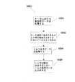
図11は、このような動作を実行するためのアルゴリズム1100を示す。アルゴリズム1100は、システム800又はモータ組立体702のプロセッサ810と組み合わせたシステム800によって実行されることができる。ステップ1102に示されるように、発射に先立って、ステップ1102においてステープラ600をクランプするためのコマンドが受信されるとき、アルゴリズム1100は開始される。 FIG. 11 shows an
ステップ1104では、シャシ608のメモリ808に格納されるステープラ600に固有のパラメータ、モータ組立体702のメモリ818に格納されるモータ組立体702に固有のパラメータ、及びデータストレージ716に格納されるカートリッジ614に固有のパラメータが、読み出される。ステップ1106では、調整された最大制限トルクが決定される。調整された最大制限トルクは、幾つかのパラメータ並びにモータ組立体702及び特定のカートリッジ614との組み合わせのステープラ600の摩耗特性に適合するモデルに基づいて決定されることができる。上述のように、モデルに含まれることができるファクタの幾つかは、モータ組立体702の温度(T)、ステープラ発射の回数によって測定されるモータ組立体702の寿命(LMP)、ステープラ発射の回数によって測定されるステープラ600の寿命(Linst)、及び手首部604の角度(θ)を含む。一般的に、パラメータのセット{Parameters}は、利用される制限トルクに影響を及ぼすものと定められることができる。幾つかの実施形態では、セットは{T、LMP、Linst、θ}と定められることができる。他のパラメータもまたモデルの中で利用され得る。In
したがって、調整された最大制限トルクは、
τcom=F({Parameters})
によって与えられることができ、ここで関数Fは、クランプ600及びモータ組立体702の寿命に渡ってクランプ600及びモータ組立体702の挙動に最も良く適合するモデルを定める。関数Fは、時間に渡る摩耗特性を正確に表すように、ステープラ600及びモータ組立体702の大きいセットに関して経験的に決定されることができる。幾つかの場合には、様々なパラメータに関連するファクタは、モデルの中でスカラーであり得るが、他の場合には、より良いモデルは、他のファクタはスカラーでありながら加法的である幾つかのファクタを有する。例えば、最大制限トルクを計算するためのモデルは、
τcom=F({Parameters})=
f(T)*g(LMP)*h(Linst)*y(θ)+z(T)+k(LMP)+x(Linst)+p(θ)+C
によって与えられ、ここでf、g、h、y、z、k、x、及びpは示されたパラメータの特定の関数を表し、Cは一般的なオフセット項を表す。上の方程式に示されるように、修正は、パラメータセットのパラメータのそれぞれに関してスカラー構成成分及び加法的構成成分を含むことができる。幾つかのモデルでは、関数f、g、h、及びyの幾つかは、対応するパラメータが加法的構成成分ではない場合に関数z、k、x、及びpが0に設定されながらパラメータがスカラー構成成分ではない場合に、1に設定されることができる。F{Parameters}の上の例は、限定するものではなく、他の関数がモデリングにおいて利用されることができる。幾つかの特定の例示のモデルは、以下にさらに詳細に示される。Therefore, the adjusted maximum torque limit is
τcom = F ({Parameters})
Where function F defines a model that best fits the behavior of
τcom = F ({Parameters}) =
f (T) * g (LMP ) * h (Linst ) * y (θ) + z (T) + k (LMP ) + x (Linst ) + p (θ) + C
Where f, g, h, y, z, k, x, and p represent specific functions of the indicated parameters, and C represents a general offset term. As shown in the equation above, the modifications can include a scalar component and an additive component for each of the parameters in the parameter set. In some models, some of the functions f, g, h, and y are scalars while the functions z, k, x, and p are set to 0 when the corresponding parameter is not an additive component. It can be set to 1 when it is not a constituent. The above example of F {Parameters} is not limiting and other functions can be utilized in the modeling. Some specific exemplary models are shown in more detail below.
ステップ1108では、モータ制限電流が制限トルクから決定される。近似として、モータ804に関して電流と所望のトルクとの間に線形関係がある。したがって、制限トルクから制限電流への変換は、クランプ工程におけるモータ804に対する制限電流を決定するために線形関係にしたがって制限トルクをスケーリング(増減)させることを含む。 In
ステップ1110では、ステープラ600は、上述の調整されたモータ制限電流を利用してクランプされる。上述のように、モータ804が特定の位置を達成しているが調整されたモータ制限電流を越えていないとき、ステープラ600はクランプされる。いったんステープラ600がクランプ状態にあると、次にステープラ600は発射されることができる。ステップ1112では、成功したクランプが達成された後、アルゴリズム1100は、発射に先立ってユーザ入力又は承認を待つ。ステップ1114では、ステープラ600は発射される。 In
図11に示されるように、幾つかの実施形態では、発射ステップ1114は、発射制限トルクを決定するステップ1120、発射モータ制限電流を決定するステップ1122、及び発射モータ制限電流を使用して発射するステップ1124を含むことができる。ステープラ600の発射カルダンジョイントに加えられる過度なトルクは、発射カルダンジョイントを破壊する又はカートリッジ614のリードネジを破壊する問題を引き起こし得る。過度なトルクはまた、カートリッジ614のナイフ616を大き過ぎる力によりハートストップ部に対して押し付けさせ、場合によりナイフ614の一部分を壊して患者の中に入れ得る。ドライブトレイン及びカートリッジリードネジ並びにナイフ機構のいずれもが、動作中の破壊を防ぐために適切な安全マージンを含むべきである。発射制限トルク(発射モータ802の制限トルク)は、機構に加えられるトルクが、ステープラカートリッジ614又はカートリッジドライブトレイン構成要素に損傷を与えるレベルに近づくことを防ぐように調整されることができる。 As shown in FIG. 11, in some embodiments, firing
ステップ1120における発射モータ802に対して発射制限トルクを決定することは、ステップ1106に関して上述したようにクランプモータ804に対して制限トルクを決定することと同様であることができる。上述のように、発射モータ802に対する発射制限トルクは、例えば、温度、モータ組立体寿命、器具寿命、及び他のパラメータの関数を使用して調整されることができる。上述のものがクランプモータ804に対する制限トルクを調整するために使用されることができるので、幾つかの場合には異なる係数を持つ、同じ形態の調整方程式が、発射モータ802に対する制限トルクを調整するのに使用されることができる。さらに、ステップ1108で上述されたようにモータ制限電流を決定するための同じ形態の方程式が、ステップ1112で利用されることができる。発射ステップ1124は、発射モータ802が特定の位置に到達する一方発射モータ制限電流を超えていないとき、完了する。 Determining the firing limit torque for firing
ステップ1116では、パラメータが発射を反映するように調整される。例えば、パラメータLMP及びLinstは両方インクリメントされることができる。ステップ1118では、調整されたパラメータは、将来の使用のために格納されることができる。例えば、モータ組立体702又はステープラ600を伴う次のステープル留め処置での使用のために、LMPはメモリ812に格納され且つLinstはメモリ808に格納される。In
上述のように、制限トルクは、ステップ1108においてモータ804に対する制限電流に変換されることができる。幾つかの場合には、制限電流と制限トルクとの間の関係は、
As described above, the limiting torque can be converted to a limiting current for
によって与えられることができ、ここでIlimitはモータ804に供給される制限電流であり、INLは較正時におけるモータ804に対する無負荷電流であり、KTはモータ組立体ドライブトレインの特徴を示すトルク定数であり、τcomは上述のように、クランプにおける誤差を最小にするように供給されるモデル化され且つ補償された制限トルクを示す。INLは、モータ組立体に対する摩擦補償を表し、速度の関数であることができる。パラメータKTは、モータ804におけるトルクの電流での変換に関連する。基準温度Trefでの初期KTは、上述のようにモータ組立体702の較正中に決定され得る。幾つかのモデルでは、KTは、
Where Ilimit is the limiting current supplied to the
によって与えられることができ、ここでKTcalは、計算された変換係数であり、ηは、モータ804の動作に関連する温度係数である。幾つかのモデルでは、INLに関する値は、
Where KTcal is the calculated conversion factor and η is the temperature factor associated with the operation of the
によって与えられることができ、ここでIcalは、速度に応じたモータ組立体702での損失を表す較正された無負荷電流引き込みであり、μは温度係数、Tは(電子装置810によって測定される)モータ組立体702の温度、Trefは基準温度、κはモータ組立体寿命係数、及びLMPは、モータ組立体702がステープラを発射した回数である。基準温度Trefは、例えば、モータ組立体702が較正されるときの温度であることができ、メモリ812に格納されることができる。このモデルの上記方程式から見ることができるように、T=Trefでのステープラ600に対する較正された制限電流は、Ilimit=Ical+τcal/KTcalによって与えられ、これはIcal及びKTcalの両方を決定するために初期較正段階で使用されることができる。Ical及びKTcalの値は、幾つかの実施形態では、メモリ812に格納されることができる。
Where Ical is a calibrated no-load current draw that represents the loss in
幾つかのモデルでは、調整された制限トルクは、
In some models, the adjusted limiting torque is
によって与えられることができ、ここでαは温度係数、βはモータ組立体702の寿命係数、γはステープラ600の寿命係数、δは一定オフセット温度係数及びεは一定オフセットである。τdesは、上述のように、τcal及びカートリッジ調整値の和によって与えられることができる。
Where α is the temperature coefficient, β is the lifetime coefficient of the
関数Wは、手首部604が関節式であるとき、加えられる摩擦を反映する。幾つかの実施形態では、関数Wは、手首部604が関節接続される角度θのコサイン関数である。そのようなものとして、幾つかの実施形態では、Wは、
The function W reflects the friction applied when the
によって与えられることができ、θは図8に示されるように手首部604の手首角度であり、ξは制限トルクへの手首角度の影響を決定するパラメータである。説明されるように、θ=0度で、W(θ)は1である。しかし、角度が増加するにつれて、手首部604の摩擦は増加し、W(θ)によるτcomの乗法的増加をもたらす。幾つかの実施形態では、関数W(θ)はルックアップテーブルとして実装されることができる。制限トルク手首調整値W(θ)は、手首部及び手首部を通して力を伝達する必要を持つ任意の手術器具に対して利用されることができる。
Where θ is the wrist angle of the
上に示された様々なスカラー係数は、モータ組立体702及びステープラ600の生涯の挙動を最も良くモデル化するように調整されることができる。これらの係数は、温度係数η、μ、α、及びδ、寿命係数κ、β、及びγ、加法的係数ε、並びに手首部係数ξを含み、ステープラ600及びモータ組立体702の寿命を通じて、ステープラ600及びモータ組立体702の様々なものの繰り返されるテストを通じて決定されることができる又は、幾つかの場合には、個々のモータ組立体又は器具に行われる較正を通じてカスタマイズされることができる。幾つかの実施形態では、係数が、多くのモータ組立体及びステープラを平均化することによって決定され且つ個々のモータ組立体又はステープラの間で変化しない場合、それらは、モデリングが計算されるシステム800に格納される。別な方法では、係数は、それらの個別の構成要素に対して格納されることができる。例えば、温度係数η、μ、α、及びδ、寿命係数κ及びβはメモリ812に格納されることができる一方、寿命係数γはメモリ808に格納されることができる。 The various scalar coefficients shown above can be adjusted to best model the lifetime behavior of the
上述のように、例えば、δは、温度がスカラ構成要素であり加法的構成要素でない場合、0に設定されることができ、αは、温度が加法的構成要素でありスカラ構成要素でない場合、0に設定されることができる。このモデルでは、両方非ゼロ温度のα及びδは両方スカラ及び加法的ファクタである。幾つかの実施形態では、係数は次の範囲内であることができる:0≦α≦1;0≦β≦1;0≦δ≦1;−10≦ε≦10;0≦γ≦1;0≦μ≦1;0≦κ≦1;0≦η≦1;及び0≦ξ≦1。多くの場合、係数は約10−2より小さい。As described above, for example, δ can be set to 0 if the temperature is a scalar component and not an additive component, and α can be set if the temperature is an additive component and not a scalar component. Can be set to zero. In this model, both non-zero temperature α and δ are both scalar and additive factors. In some embodiments, the coefficients can be in the following ranges: 0 ≦ α ≦ 1; 0 ≦ β ≦ 1; 0 ≦ δ ≦ 1; −10 ≦ ε ≦ 10; 0 ≦ γ ≦ 1; 0 ≦ μ ≦ 1; 0 ≦ κ ≦ 1; 0 ≦ η ≦ 1; and 0 ≦ ξ ≦ 1. Often, the coefficient is about10-2 less.
上に提供される主にスカラモデルの例は、温度に応じた生涯のドリフトに対してステープラ600の動作のための制限トルクを調整するために利用されることができる唯一のモデルではない。他のモデルが利用されることができ、例えば、主に加法的なモデル又は加法的及びスカラ構成要素の組み合わせが加えられることができる、又は非線形モデルが使用されることができる。モデルは、必要に応じて、その生涯の使用の間にステープラ600の挙動を最も良くモデル化するために、乗法的及び加法的ファクタの組み合わせを含むように、拡張されることができる。 The primarily scalar model example provided above is not the only model that can be utilized to adjust the limiting torque for the operation of the
上で提案されるように、制限トルクの調整をモデル化するために利用されることができる様々なモデルがある。上で提案されるように、システムに応じて、幾つかの変数は加法的効果としてモデル化され得るとともに他のものは乗法的効果としてモデル化され得る。幾つかの実施形態では、モデルは、特定のステープラシステムの寿命に対して適合されることができる。これは、パラメータの幾つかをゼロに及び幾つかを非ゼロ値に設定することによって、達成されることができる。幾つかの実施形態では、τcomに対するモデル化方程式は、モデル化において多くの加法的ファクタ並びに加法的及び乗法的ファクタのさらなる組み合わせを含むように拡張されることができる。As suggested above, there are various models that can be utilized to model the limit torque adjustment. As suggested above, depending on the system, some variables can be modeled as additive effects and others can be modeled as multiplicative effects. In some embodiments, the model can be adapted for the lifetime of a particular stapler system. This can be achieved by setting some of the parameters to zero and some to non-zero values. In some embodiments, the modeling equation for τcom can be extended to include many additive factors and additional combinations of additive and multiplicative factors in the modeling.
クランプモータ804を制御するために用いられる制限電流、Ilimitは、モータ804を制御するために電子装置810に供給されることができる。調整された制限電流を供給するために用いられるモデルは、ステープラ600及びモータ組立体702の動作可能な寿命に渡って適切なクランプを提供するように動作する。上述のトルク補償アルゴリズムは、ステープラ600を利用する手術システムが適切な材料(及び厚さ)を効果的且つ安全にクランプすることを可能にする一方、適切な組織隙間を維持し、不適切な組織隙間をもたらす材料(及び厚さ)の完全なクランプを防ぎ得る。この動作は、過度な先端たわみを防ぐのに役立ち、また、発射並びに不適切に形成されるステープル及び不適切に形成されるステープルから生じる外科処置をもたらすことを防ぐ。The limiting current, Ilimit , used to control the
ホーミング調整
本発明の幾つかの実施形態では、ホーミング(homing)手順が、制限トルクをさらに調整するために提供されることができる。ホーミング手順は、ステープラ600及びモータ組立体702が患者側カート22に最初に取り付けられるとき、実行される。幾つかの実施形態では、システム800は、動作の予め設定された範囲でステープラ600を駆動することができ、ステープラ600及びモータ組立体702の対応するパフォーマンスをモニタしながらテストする。モータ804及び802の電流、位置、及びトルクが電子装置810によってモニタされ且つプロセッサ800に伝達されることができる。プロセッサ800は、ホーミングの間のステープラ600及びモータ組立体702の測定された挙動を補正するために係数及びパラメータを調整することができる。これらの補正された係数及びパラメータは、上述のようにモータ組立体702を持つステープラ600を操作する間に利用されることができる。Homing Adjustment In some embodiments of the present invention, a homing procedure can be provided to further adjust the limiting torque. The homing procedure is performed when the
個別のパラメータは、パフォーマンス試験にしたがって調整されることができる。このようなものとして、較正データ、例えば、τcalは、ステープラ600の利用に先立って、上述のファクタに加えて、ホーミング工程の結果として調整されることができる。Individual parameters can be adjusted according to performance tests. As such, calibration data, eg, τcal , can be adjusted as a result of the homing process, in addition to the above factors, prior to use of the
上述の詳細な説明は、本発明の特定の実施形態を説明するために提供され、限定することが意図されるものではない。本発明の範囲内の多くの変形及び変更が可能である。本発明は、以下の請求項に述べられる。 The above detailed descriptions are provided to illustrate specific embodiments of the present invention and are not intended to be limiting. Many variations and modifications within the scope of the present invention are possible. The invention is set forth in the following claims.
Claims (28)
Translated fromJapanese前記制御電子装置が、前記クランプ器具に対する初期トルク限度を取得するステップ;
前記制御電子装置が、モータ組立体の寿命、前記クランプ器具の寿命、又は前記モータ組立体の前記寿命及び前記クランプ器具の前記寿命の両方に基づいて、調整されたトルク限度を取得するために前記初期トルク限度を調整するステップ;及び
前記制御電子装置が、前記モータ組立体に、前記調整されたトルク限度にしたがって前記クランプ器具をクランプさせるステップ;を含む、
方法。A method foroperatinga clamping devicehaving control electronics comprising :
Stepwherein the control electronics is, to obtain the firstQuito torquelimit for the clamping device;
The control electronics is the life of the motor assembly, the life of the clamping device, or on the basis of the both the life of the lifetime and the clamping device of the motor assembly,in order to obtainthe adjustedtorquelimits and; step for adjusting thepre-Symbolinitial torquelimit
Including;the control electronics is in the motor assembly, the step of clamping the clamping device in accordance with theadjusted torquelimits
Method.
請求項1に記載の方法。Step of acquiring the firstQuito torquelimit, comprising the step of reading the firstQuito torquelimit from the clamping device,
The method of claim 1.
請求項1に記載の方法。The step of adjusting the initial torque limit in order to obtain the adjusted torque limitsfurtherbased on one or moreof the wrist angleof the temperatureor the clamping deviceofthe motor assembly,
The method of claim 1.
前記初期トルク限度を調整するステップは、前記モータ組立体の前記温度、前記モータ組立体の前記寿命、前記クランプ器具の前記寿命、及び前記手首部角度の関数によって前記初期トルク限度を増減させるステップを含む、
請求項3に記載の方法。The control electronics further comprises a step of readingthe lifeofthe lifetime and the clamping deviceof the motor assembly,
The step of adjusting theinitial torquelimit,the temperatureof the motor assembly,the service lifeof the motor assembly, thereby decreasing the initialQuito torquelimit bythe lifetime, and the wrist unit angle of the functionof the clamping device Including steps,
The method of claim 3.
前記初期トルク限度を調整するステップは、前記初期トルク限度に、前記モータ組立体の前記温度、前記モータ組立体の前記寿命、前記クランプ器具の前記寿命、及び前記手首部角度の関数を加えるステップを含む、
請求項3に記載の方法。The control electronics further comprises a step of readingthe lifeofthe lifetime and the clamping deviceof the motor assembly,
The step of adjusting theinitial torquelimit, the the firstQuito torquelimit, addingthe temperature,the lifeof the motor assemblyof the motor assembly,the service lifeof the clamping device, and the function of the wrist angle Including steps,
The method of claim 3.
によって達成され、τcomは前記調整されたトルク限度、τdesは所望のトルク限度、W(θ)は前記手首部角度に対するスケーリング調整、Tは前記モータ組立体の前記温度、LMPは前記モータ組立体の前記寿命、Linsは前記クランプ器具の前記寿命、Trefは基準温度、並びに、α、β、γ、δ及びεは係数である、
請求項3に記載の方法。Adjusting theinitial torquelimit comprises:
Be achieved by, taucom is theadjusted torquelimits, taudes isthe desired torquelimit, W (θ) is scaled adjustment to the wrist angle, T isthe temperatureof the motorassembly, L MP isthe lifeof the motorassembly, L ins isthe lifeof the clampingdevice, T ref is a reference temperature, as well as, alpha, beta, gamma, the δ and ε is a coefficient,
The method of claim 3.
請求項6に記載の方法。The clamping device is a stapler, it saiddesired torquelimit taudes is thetorquelimit has been calibrated for the clamping device to be adjusted in accordance with the cartridge adjustment,
The method of claim 6.
によって与えられ、θは前記手首部角度でありξは係数である、
請求項6に記載の方法。W (θ) is
Where θ is the wrist angle and ξ is a coefficient.
The method of claim 6.
前記モータ組立体のクランプモータに対する電流限度を計算するステップ;及び
電流を前記電流限度に制限しながら前記クランプモータをクランプ位置に駆動するステップ、を含む、
請求項3に記載の方法。Step of clamping the clamping device in accordance with theadjusted torquelimits,
Comprising the step of driving the clamp motor in the clamping position while limiting and current beforeSL currentlimit; step calculates thethat currentlimit against the clamp motorof the motor assembly
The method of claim 3.
によって提供され、Ilimitは前記電流限度であり、INLは無負荷電流であり、τcomは前記調整されたトルク限度であり、KTは前記クランプモータに対する電流からトルクへの変換パラメータである、
請求項9に記載の方法。Calculating apre-SL currentlimit,
Is providedby, I limit is the previousSL currentlimit, I NL is the no-load current, taucom is theadjusted torquelimits,K T is converted into the torque from current to the clamp motor Parameter,
The method of claim 9.
請求項10に記載の方法。The INL and the KT is adjusted tothe temperature andthe lifetimeofthe motor assemblyof the motor assembly,
The method of claim 10.
請求項10に記載の方法。The INL is a function ofthe speed of theclamp motor and the direction of theclamp motor .
The method of claim 10.
前記制御電子装置が、前記クランプ器具を発射させるステップ;
前記制御電子装置が、前記モータ組立体の前記寿命及び前記クランプ器具の前記寿命を更新するステップ;及び
前記制御電子装置が、前記モータ組立体の前記寿命及び前記クランプ器具の前記寿命を格納するステップ;をさらに含む、
請求項9に記載の方法。The clamping device is a stapler and the method is:
The control electronics is, Ruwas fired the clamping device step;
Stepwherein the control electronics is, updatesthe lifetimeofthe lifetime and the clamping deviceof the motor assembly; and
The control electronics is, storingthe service lifeofthe lifetime and the clamping deviceof the motor assembly; further including,
The method of claim 9.
前記制御電子装置が、前記の駆動中に前記クランプ器具を監視するステップ;及び
前記制御電子装置が、さらに前記監視するステップに基づいて、前記調整されたトルク限度を得るように前記初期トルク限度を調整するステップ;をさらに含む、
請求項1に記載の方法。The control electronicsdriving the clampingdevice in an operating range ;
The control electronics monitoring the clamping instrument during the driving; and
The control electronics further comprising adjusting the initial torque limit to obtain the adjusted torque limit based on the monitoring step;
The method of claim 1.
前記クランプ装置に結合されるモータ組立体のモータからデータを受信し且つ前記モータを制御するように前記モータ組立体に結合されるプロセッサを有し、前記プロセッサは、
前記クランプ装置に対する初期トルク限度を取得するための;
前記モータ組立体の寿命、前記クランプ装置の寿命、又は前記モータ組立体の前記寿命及び前記クランプ装置の前記寿命の両方に基づいて、調整されたトルク限度を取得するために前記初期トルク限度を調整するための;及び
前記調整されたトルク限度にしたがって前記クランプ装置をクランプさせるための;命令を実行する、
システム。A system that uses a clamping device:
Receiving a data from a motor of a motor assembly coupled to the clampingdevice and having a processor coupled to themotor assembly to control themotor , the processor comprising:
For obtaining the firstQuito torquelimit for the clampingdevice;
Life of the motor assembly,the initial torquelimitlife of the clamping device, or on the basis of the both the life of the life and the clamping device of the motor assembly,in order to obtainthe adjustedtorquelimits executing instructions; for clamping the clampingdevice in accordance with and theadjusted torquelimits; for adjusting the
system.
請求項15に記載のシステム。Obtaining the firstQuito torquelimit comprises reading the firstQuito torquelimit from the clampingdevice,
The system according to claim 15.
請求項15に記載のシステム。Wherein adjusting the initial torque limit in order to obtain the adjusted torque limitsfurtherbased on one or moreof the wrist angleof the temperatureand the clampingdeviceofthe motor assembly,
The system according to claim 15.
前記初期トルク限度を調整することは、前記モータ組立体の前記温度、前記モータ組立体の前記寿命、前記クランプ装置の前記寿命、及び前記手首部角度の関数によって前記初期トルク限度を増減させることを含む、
請求項17に記載のシステム。Further comprising readingthe lifeof the clampingdevicefromthe lifetime andthe clamping deviceof the motor assembly from themotor assembly,
Adjusting theinitial torquelimit,the temperatureof the motor assembly,the service lifeof the motor assembly, thereby decreasing the initialQuito torquelimit bythe lifetime, and the wrist unit angle of the functionof the clampingdevice Including that,
The system of claim 17.
前記初期トルク限度を調整することは、前記初期トルク限度に、前記モータ組立体の前記温度、前記モータ組立体の前記寿命、前記クランプ装置の前記寿命、及び前記手首部角度の関数を加えることを含む、
請求項17に記載のシステム。Further comprising readingthe life andthe lifeof the clampingdeviceof the motor assembly,
Adjusting theinitial torquelimit, the the firstQuito torquelimit, addingthe temperatureof the motor assembly,the service lifeof the motor assembly,the service lifeof the clampingdevice, and the function of the wrist angle Including that,
The system of claim 17.
によって達成され、τcomは前記調整されたトルク限度、τdesは所望のトルク限度、W(θ)は前記手首部角度に対するスケーリング調整、Tは前記モータ組立体の前記温度、LMPは前記モータ組立体の前記寿命、Linsは前記クランプ装置の前記寿命、Trefは基準温度、並びに、α、β、γ、δ及びεは係数である、
請求項17に記載のシステム。Adjusting theinitial torquelimit includes
Be achieved by, taucom is theadjusted torquelimits, taudes isthe desired torquelimit, W (θ) is scaled adjustment to the wrist angle, T isthe temperature of the motorassembly, L MP isthe life of the motorassembly, L ins isthe life of the clampingdevice, T ref is a reference temperature, as well as, alpha, beta, gamma, the δ and ε is a coefficient,
The system of claim 17.
請求項20に記載のシステム。The clampingdevice is a stapler, saiddesired torquelimit taudes is acalibrated torquelimit for the clampingdevice to be adjusted in accordance with the cartridge adjustment,
The system according to claim 20.
によって与えられ、θは前記手首部角度でありξは係数である、
請求項20に記載のシステム。W (θ) is
Where θ is the wrist angle and ξ is a coefficient.
The system according to claim 20.
前記モータに対する電流限度を計算すること;及び
電流を前記電流限度に制限しながら前記モータをクランプ位置に駆動すること;を含む、
請求項17に記載のシステム。Thereby clamping the clampingdevice in accordance with theadjusted torquelimits,
Including; driving the clamping positionLiver over data before while limiting and current beforeSL currentlimit; it calculates thethat currentlimit againstthe motor
The system of claim17 .
によって提供され、Ilimitは前記電流限度であり、INLは無負荷電流であり、τcomは前記調整されたトルク限度であり、KTは前記モータに対する電流変換パラメータである、
請求項23に記載のシステム。It is possible to calculate thepre-SL currentlimit,
Is providedby, I limit is the previousSL currentlimit, I NL is the no-load current, taucom is theadjusted torquelimits,K T is a current conversion parameter for the previousliver over data is there,
24. The system of claim 23.
請求項24に記載のシステム。The INL and the KT is adjusted tothe temperature andthe lifetimeofthe motor assemblyof the motor assembly,
25. The system according to claim 24.
請求項24に記載のシステム。TheI NL is the speed and function of the directionof the motorofthe motor,
25. The system according to claim 24.
前記クランプ装置を発射させること;
前記モータ組立体の前記寿命及び前記クランプ装置の前記寿命を更新すること;及び
更新された前記モータ組立体の前記寿命及び更新された前記クランプ装置の前記寿命を格納すること;をさらに含む、
請求項15に記載のシステム。The clamping device is a stapler;
Rukotois fired the clampingdevice;
It updatesthe lifetime andthe lifetimeofthe clampingdeviceofthe motor assembly; and
Storingthe life andupdatedthe lifetimeof the clampingdeviceof theupdated the motor assembly; further including,
The system according to claim 15.
前記の駆動中に前記クランプ装置を監視すること;及び
さらに前記監視することに基づいて、前記調整されたトルク限度を得るように前記初期トルク限度を調整すること;をさらに含む、
請求項15に記載のシステム。
Driving the clampingdevice in anoperating range ;
Monitoring the clamping device during the driving; and
Further adjusting the initial torque limit to obtain the adjusted torque limit based on the monitoring ;
The system according to claim 15.
Applications Claiming Priority (5)
| Application Number | Priority Date | Filing Date | Title |
|---|---|---|---|
| US201361752402P | 2013-01-14 | 2013-01-14 | |
| US61/752,402 | 2013-01-14 | ||
| US14/154,075US9675354B2 (en) | 2013-01-14 | 2014-01-13 | Torque compensation |
| US14/154,075 | 2014-01-13 | ||
| PCT/US2014/011455WO2014110564A1 (en) | 2013-01-14 | 2014-01-14 | Torque compensation |
Related Child Applications (1)
| Application Number | Title | Priority Date | Filing Date |
|---|---|---|---|
| JP2018160210ADivisionJP2019034154A (en) | 2013-01-14 | 2018-08-29 | Torque compensation |
Publications (2)
| Publication Number | Publication Date |
|---|---|
| JP2016502923A JP2016502923A (en) | 2016-02-01 |
| JP6396326B2true JP6396326B2 (en) | 2018-09-26 |
Family
ID=51165714
Family Applications (3)
| Application Number | Title | Priority Date | Filing Date |
|---|---|---|---|
| JP2015552892AActiveJP6396326B2 (en) | 2013-01-14 | 2014-01-14 | Torque compensation |
| JP2018160210APendingJP2019034154A (en) | 2013-01-14 | 2018-08-29 | Torque compensation |
| JP2020026840AActiveJP7072594B2 (en) | 2013-01-14 | 2020-02-20 | Torque compensation |
Family Applications After (2)
| Application Number | Title | Priority Date | Filing Date |
|---|---|---|---|
| JP2018160210APendingJP2019034154A (en) | 2013-01-14 | 2018-08-29 | Torque compensation |
| JP2020026840AActiveJP7072594B2 (en) | 2013-01-14 | 2020-02-20 | Torque compensation |
Country Status (6)
| Country | Link |
|---|---|
| US (4) | US9675354B2 (en) |
| EP (1) | EP2943136B1 (en) |
| JP (3) | JP6396326B2 (en) |
| KR (2) | KR102253470B1 (en) |
| CN (2) | CN108433759B (en) |
| WO (1) | WO2014110564A1 (en) |
Families Citing this family (569)
| Publication number | Priority date | Publication date | Assignee | Title |
|---|---|---|---|---|
| US20070084897A1 (en) | 2003-05-20 | 2007-04-19 | Shelton Frederick E Iv | Articulating surgical stapling instrument incorporating a two-piece e-beam firing mechanism |
| US9060770B2 (en) | 2003-05-20 | 2015-06-23 | Ethicon Endo-Surgery, Inc. | Robotically-driven surgical instrument with E-beam driver |
| US11998198B2 (en) | 2004-07-28 | 2024-06-04 | Cilag Gmbh International | Surgical stapling instrument incorporating a two-piece E-beam firing mechanism |
| US8215531B2 (en) | 2004-07-28 | 2012-07-10 | Ethicon Endo-Surgery, Inc. | Surgical stapling instrument having a medical substance dispenser |
| US11890012B2 (en) | 2004-07-28 | 2024-02-06 | Cilag Gmbh International | Staple cartridge comprising cartridge body and attached support |
| US9072535B2 (en) | 2011-05-27 | 2015-07-07 | Ethicon Endo-Surgery, Inc. | Surgical stapling instruments with rotatable staple deployment arrangements |
| US11246590B2 (en) | 2005-08-31 | 2022-02-15 | Cilag Gmbh International | Staple cartridge including staple drivers having different unfired heights |
| US7934630B2 (en) | 2005-08-31 | 2011-05-03 | Ethicon Endo-Surgery, Inc. | Staple cartridges for forming staples having differing formed staple heights |
| US11484312B2 (en) | 2005-08-31 | 2022-11-01 | Cilag Gmbh International | Staple cartridge comprising a staple driver arrangement |
| US10159482B2 (en) | 2005-08-31 | 2018-12-25 | Ethicon Llc | Fastener cartridge assembly comprising a fixed anvil and different staple heights |
| US7669746B2 (en) | 2005-08-31 | 2010-03-02 | Ethicon Endo-Surgery, Inc. | Staple cartridges for forming staples having differing formed staple heights |
| US9237891B2 (en) | 2005-08-31 | 2016-01-19 | Ethicon Endo-Surgery, Inc. | Robotically-controlled surgical stapling devices that produce formed staples having different lengths |
| US20070106317A1 (en) | 2005-11-09 | 2007-05-10 | Shelton Frederick E Iv | Hydraulically and electrically actuated articulation joints for surgical instruments |
| US11224427B2 (en) | 2006-01-31 | 2022-01-18 | Cilag Gmbh International | Surgical stapling system including a console and retraction assembly |
| US7753904B2 (en) | 2006-01-31 | 2010-07-13 | Ethicon Endo-Surgery, Inc. | Endoscopic surgical instrument with a handle that can articulate with respect to the shaft |
| US8186555B2 (en) | 2006-01-31 | 2012-05-29 | Ethicon Endo-Surgery, Inc. | Motor-driven surgical cutting and fastening instrument with mechanical closure system |
| US20120292367A1 (en) | 2006-01-31 | 2012-11-22 | Ethicon Endo-Surgery, Inc. | Robotically-controlled end effector |
| US8708213B2 (en) | 2006-01-31 | 2014-04-29 | Ethicon Endo-Surgery, Inc. | Surgical instrument having a feedback system |
| US8820603B2 (en) | 2006-01-31 | 2014-09-02 | Ethicon Endo-Surgery, Inc. | Accessing data stored in a memory of a surgical instrument |
| US20110024477A1 (en) | 2009-02-06 | 2011-02-03 | Hall Steven G | Driven Surgical Stapler Improvements |
| US11278279B2 (en) | 2006-01-31 | 2022-03-22 | Cilag Gmbh International | Surgical instrument assembly |
| US20110295295A1 (en) | 2006-01-31 | 2011-12-01 | Ethicon Endo-Surgery, Inc. | Robotically-controlled surgical instrument having recording capabilities |
| US11793518B2 (en) | 2006-01-31 | 2023-10-24 | Cilag Gmbh International | Powered surgical instruments with firing system lockout arrangements |
| US7845537B2 (en) | 2006-01-31 | 2010-12-07 | Ethicon Endo-Surgery, Inc. | Surgical instrument having recording capabilities |
| US8992422B2 (en) | 2006-03-23 | 2015-03-31 | Ethicon Endo-Surgery, Inc. | Robotically-controlled endoscopic accessory channel |
| US8322455B2 (en) | 2006-06-27 | 2012-12-04 | Ethicon Endo-Surgery, Inc. | Manually driven surgical cutting and fastening instrument |
| US10568652B2 (en) | 2006-09-29 | 2020-02-25 | Ethicon Llc | Surgical staples having attached drivers of different heights and stapling instruments for deploying the same |
| US11980366B2 (en) | 2006-10-03 | 2024-05-14 | Cilag Gmbh International | Surgical instrument |
| US8632535B2 (en) | 2007-01-10 | 2014-01-21 | Ethicon Endo-Surgery, Inc. | Interlock and surgical instrument including same |
| US11291441B2 (en) | 2007-01-10 | 2022-04-05 | Cilag Gmbh International | Surgical instrument with wireless communication between control unit and remote sensor |
| US8684253B2 (en) | 2007-01-10 | 2014-04-01 | Ethicon Endo-Surgery, Inc. | Surgical instrument with wireless communication between a control unit of a robotic system and remote sensor |
| US20080169333A1 (en) | 2007-01-11 | 2008-07-17 | Shelton Frederick E | Surgical stapler end effector with tapered distal end |
| US11039836B2 (en) | 2007-01-11 | 2021-06-22 | Cilag Gmbh International | Staple cartridge for use with a surgical stapling instrument |
| US7673782B2 (en) | 2007-03-15 | 2010-03-09 | Ethicon Endo-Surgery, Inc. | Surgical stapling instrument having a releasable buttress material |
| US8931682B2 (en) | 2007-06-04 | 2015-01-13 | Ethicon Endo-Surgery, Inc. | Robotically-controlled shaft based rotary drive systems for surgical instruments |
| US11564682B2 (en) | 2007-06-04 | 2023-01-31 | Cilag Gmbh International | Surgical stapler device |
| US7753245B2 (en) | 2007-06-22 | 2010-07-13 | Ethicon Endo-Surgery, Inc. | Surgical stapling instruments |
| US11849941B2 (en) | 2007-06-29 | 2023-12-26 | Cilag Gmbh International | Staple cartridge having staple cavities extending at a transverse angle relative to a longitudinal cartridge axis |
| US8573465B2 (en) | 2008-02-14 | 2013-11-05 | Ethicon Endo-Surgery, Inc. | Robotically-controlled surgical end effector system with rotary actuated closure systems |
| US7819298B2 (en) | 2008-02-14 | 2010-10-26 | Ethicon Endo-Surgery, Inc. | Surgical stapling apparatus with control features operable with one hand |
| US11986183B2 (en) | 2008-02-14 | 2024-05-21 | Cilag Gmbh International | Surgical cutting and fastening instrument comprising a plurality of sensors to measure an electrical parameter |
| US7866527B2 (en) | 2008-02-14 | 2011-01-11 | Ethicon Endo-Surgery, Inc. | Surgical stapling apparatus with interlockable firing system |
| US9179912B2 (en) | 2008-02-14 | 2015-11-10 | Ethicon Endo-Surgery, Inc. | Robotically-controlled motorized surgical cutting and fastening instrument |
| JP5410110B2 (en) | 2008-02-14 | 2014-02-05 | エシコン・エンド−サージェリィ・インコーポレイテッド | Surgical cutting / fixing instrument with RF electrode |
| US8636736B2 (en) | 2008-02-14 | 2014-01-28 | Ethicon Endo-Surgery, Inc. | Motorized surgical cutting and fastening instrument |
| US8758391B2 (en) | 2008-02-14 | 2014-06-24 | Ethicon Endo-Surgery, Inc. | Interchangeable tools for surgical instruments |
| US9585657B2 (en) | 2008-02-15 | 2017-03-07 | Ethicon Endo-Surgery, Llc | Actuator for releasing a layer of material from a surgical end effector |
| US9005230B2 (en) | 2008-09-23 | 2015-04-14 | Ethicon Endo-Surgery, Inc. | Motorized surgical instrument |
| US9386983B2 (en) | 2008-09-23 | 2016-07-12 | Ethicon Endo-Surgery, Llc | Robotically-controlled motorized surgical instrument |
| US11648005B2 (en) | 2008-09-23 | 2023-05-16 | Cilag Gmbh International | Robotically-controlled motorized surgical instrument with an end effector |
| US8210411B2 (en) | 2008-09-23 | 2012-07-03 | Ethicon Endo-Surgery, Inc. | Motor-driven surgical cutting instrument |
| US8608045B2 (en) | 2008-10-10 | 2013-12-17 | Ethicon Endo-Sugery, Inc. | Powered surgical cutting and stapling apparatus with manually retractable firing system |
| US8517239B2 (en) | 2009-02-05 | 2013-08-27 | Ethicon Endo-Surgery, Inc. | Surgical stapling instrument comprising a magnetic element driver |
| RU2525225C2 (en) | 2009-02-06 | 2014-08-10 | Этикон Эндо-Серджери, Инк. | Improvement of drive surgical suturing instrument |
| US8851354B2 (en) | 2009-12-24 | 2014-10-07 | Ethicon Endo-Surgery, Inc. | Surgical cutting instrument that analyzes tissue thickness |
| US8220688B2 (en) | 2009-12-24 | 2012-07-17 | Ethicon Endo-Surgery, Inc. | Motor-driven surgical cutting instrument with electric actuator directional control assembly |
| US8783543B2 (en) | 2010-07-30 | 2014-07-22 | Ethicon Endo-Surgery, Inc. | Tissue acquisition arrangements and methods for surgical stapling devices |
| US11298125B2 (en) | 2010-09-30 | 2022-04-12 | Cilag Gmbh International | Tissue stapler having a thickness compensator |
| US9016542B2 (en) | 2010-09-30 | 2015-04-28 | Ethicon Endo-Surgery, Inc. | Staple cartridge comprising compressible distortion resistant components |
| US12213666B2 (en) | 2010-09-30 | 2025-02-04 | Cilag Gmbh International | Tissue thickness compensator comprising layers |
| US9351730B2 (en) | 2011-04-29 | 2016-05-31 | Ethicon Endo-Surgery, Llc | Tissue thickness compensator comprising channels |
| US9386988B2 (en) | 2010-09-30 | 2016-07-12 | Ethicon End-Surgery, LLC | Retainer assembly including a tissue thickness compensator |
| US11812965B2 (en) | 2010-09-30 | 2023-11-14 | Cilag Gmbh International | Layer of material for a surgical end effector |
| US11925354B2 (en) | 2010-09-30 | 2024-03-12 | Cilag Gmbh International | Staple cartridge comprising staples positioned within a compressible portion thereof |
| US10945731B2 (en) | 2010-09-30 | 2021-03-16 | Ethicon Llc | Tissue thickness compensator comprising controlled release and expansion |
| US9629814B2 (en) | 2010-09-30 | 2017-04-25 | Ethicon Endo-Surgery, Llc | Tissue thickness compensator configured to redistribute compressive forces |
| US9788834B2 (en) | 2010-09-30 | 2017-10-17 | Ethicon Llc | Layer comprising deployable attachment members |
| US8695866B2 (en) | 2010-10-01 | 2014-04-15 | Ethicon Endo-Surgery, Inc. | Surgical instrument having a power control circuit |
| AU2012250197B2 (en) | 2011-04-29 | 2017-08-10 | Ethicon Endo-Surgery, Inc. | Staple cartridge comprising staples positioned within a compressible portion thereof |
| US11207064B2 (en) | 2011-05-27 | 2021-12-28 | Cilag Gmbh International | Automated end effector component reloading system for use with a robotic system |
| BR112014024098B1 (en) | 2012-03-28 | 2021-05-25 | Ethicon Endo-Surgery, Inc. | staple cartridge |
| MX358135B (en) | 2012-03-28 | 2018-08-06 | Ethicon Endo Surgery Inc | Tissue thickness compensator comprising a plurality of layers. |
| JP6224070B2 (en) | 2012-03-28 | 2017-11-01 | エシコン・エンド−サージェリィ・インコーポレイテッドEthicon Endo−Surgery,Inc. | Retainer assembly including tissue thickness compensator |
| US11871901B2 (en) | 2012-05-20 | 2024-01-16 | Cilag Gmbh International | Method for situational awareness for surgical network or surgical network connected device capable of adjusting function based on a sensed situation or usage |
| US9101358B2 (en) | 2012-06-15 | 2015-08-11 | Ethicon Endo-Surgery, Inc. | Articulatable surgical instrument comprising a firing drive |
| US9282974B2 (en) | 2012-06-28 | 2016-03-15 | Ethicon Endo-Surgery, Llc | Empty clip cartridge lockout |
| US12383267B2 (en) | 2012-06-28 | 2025-08-12 | Cilag Gmbh International | Robotically powered surgical device with manually-actuatable reversing system |
| US9289256B2 (en) | 2012-06-28 | 2016-03-22 | Ethicon Endo-Surgery, Llc | Surgical end effectors having angled tissue-contacting surfaces |
| JP6290201B2 (en) | 2012-06-28 | 2018-03-07 | エシコン・エンド−サージェリィ・インコーポレイテッドEthicon Endo−Surgery,Inc. | Lockout for empty clip cartridge |
| US20140001231A1 (en) | 2012-06-28 | 2014-01-02 | Ethicon Endo-Surgery, Inc. | Firing system lockout arrangements for surgical instruments |
| US9408606B2 (en) | 2012-06-28 | 2016-08-09 | Ethicon Endo-Surgery, Llc | Robotically powered surgical device with manually-actuatable reversing system |
| BR112014032776B1 (en) | 2012-06-28 | 2021-09-08 | Ethicon Endo-Surgery, Inc | SURGICAL INSTRUMENT SYSTEM AND SURGICAL KIT FOR USE WITH A SURGICAL INSTRUMENT SYSTEM |
| US11278284B2 (en) | 2012-06-28 | 2022-03-22 | Cilag Gmbh International | Rotary drive arrangements for surgical instruments |
| US9675354B2 (en)* | 2013-01-14 | 2017-06-13 | Intuitive Surgical Operations, Inc. | Torque compensation |
| US9522003B2 (en)* | 2013-01-14 | 2016-12-20 | Intuitive Surgical Operations, Inc. | Clamping instrument |
| BR112015021082B1 (en) | 2013-03-01 | 2022-05-10 | Ethicon Endo-Surgery, Inc | surgical instrument |
| RU2672520C2 (en) | 2013-03-01 | 2018-11-15 | Этикон Эндо-Серджери, Инк. | Hingedly turnable surgical instruments with conducting ways for signal transfer |
| US9629629B2 (en) | 2013-03-14 | 2017-04-25 | Ethicon Endo-Surgey, LLC | Control systems for surgical instruments |
| US9808244B2 (en) | 2013-03-14 | 2017-11-07 | Ethicon Llc | Sensor arrangements for absolute positioning system for surgical instruments |
| US9826976B2 (en) | 2013-04-16 | 2017-11-28 | Ethicon Llc | Motor driven surgical instruments with lockable dual drive shafts |
| BR112015026109B1 (en) | 2013-04-16 | 2022-02-22 | Ethicon Endo-Surgery, Inc | surgical instrument |
| MX369362B (en) | 2013-08-23 | 2019-11-06 | Ethicon Endo Surgery Llc | Firing member retraction devices for powered surgical instruments. |
| US9775609B2 (en) | 2013-08-23 | 2017-10-03 | Ethicon Llc | Tamper proof circuit for surgical instrument battery pack |
| US9962161B2 (en) | 2014-02-12 | 2018-05-08 | Ethicon Llc | Deliverable surgical instrument |
| EP4248901A3 (en) | 2014-03-17 | 2023-11-29 | Intuitive Surgical Operations, Inc. | System and method for breakaway clutching in an articulated arm |
| US12232723B2 (en) | 2014-03-26 | 2025-02-25 | Cilag Gmbh International | Systems and methods for controlling a segmented circuit |
| US10013049B2 (en) | 2014-03-26 | 2018-07-03 | Ethicon Llc | Power management through sleep options of segmented circuit and wake up control |
| BR112016021943B1 (en) | 2014-03-26 | 2022-06-14 | Ethicon Endo-Surgery, Llc | SURGICAL INSTRUMENT FOR USE BY AN OPERATOR IN A SURGICAL PROCEDURE |
| US20150272580A1 (en) | 2014-03-26 | 2015-10-01 | Ethicon Endo-Surgery, Inc. | Verification of number of battery exchanges/procedure count |
| US10004497B2 (en) | 2014-03-26 | 2018-06-26 | Ethicon Llc | Interface systems for use with surgical instruments |
| CN106163445B (en) | 2014-03-31 | 2019-11-29 | 直观外科手术操作公司 | Surgical instruments with switchable drives |
| US20150297225A1 (en) | 2014-04-16 | 2015-10-22 | Ethicon Endo-Surgery, Inc. | Fastener cartridges including extensions having different configurations |
| US10327764B2 (en) | 2014-09-26 | 2019-06-25 | Ethicon Llc | Method for creating a flexible staple line |
| CN106456159B (en) | 2014-04-16 | 2019-03-08 | 伊西康内外科有限责任公司 | Fastener Cartridge Assembly and Nail Retainer Cover Arrangement |
| CN106456176B (en) | 2014-04-16 | 2019-06-28 | 伊西康内外科有限责任公司 | Fastener Cartridge Including Extensions With Different Configurations |
| US10470768B2 (en) | 2014-04-16 | 2019-11-12 | Ethicon Llc | Fastener cartridge including a layer attached thereto |
| BR112016023825B1 (en) | 2014-04-16 | 2022-08-02 | Ethicon Endo-Surgery, Llc | STAPLE CARTRIDGE FOR USE WITH A SURGICAL STAPLER AND STAPLE CARTRIDGE FOR USE WITH A SURGICAL INSTRUMENT |
| BR112017004361B1 (en) | 2014-09-05 | 2023-04-11 | Ethicon Llc | ELECTRONIC SYSTEM FOR A SURGICAL INSTRUMENT |
| US10135242B2 (en) | 2014-09-05 | 2018-11-20 | Ethicon Llc | Smart cartridge wake up operation and data retention |
| US11311294B2 (en) | 2014-09-05 | 2022-04-26 | Cilag Gmbh International | Powered medical device including measurement of closure state of jaws |
| US10105142B2 (en) | 2014-09-18 | 2018-10-23 | Ethicon Llc | Surgical stapler with plurality of cutting elements |
| CN107427300B (en) | 2014-09-26 | 2020-12-04 | 伊西康有限责任公司 | Surgical suture buttresses and auxiliary materials |
| US11523821B2 (en) | 2014-09-26 | 2022-12-13 | Cilag Gmbh International | Method for creating a flexible staple line |
| US10076325B2 (en) | 2014-10-13 | 2018-09-18 | Ethicon Llc | Surgical stapling apparatus comprising a tissue stop |
| US9924944B2 (en) | 2014-10-16 | 2018-03-27 | Ethicon Llc | Staple cartridge comprising an adjunct material |
| US11141153B2 (en) | 2014-10-29 | 2021-10-12 | Cilag Gmbh International | Staple cartridges comprising driver arrangements |
| US10517594B2 (en) | 2014-10-29 | 2019-12-31 | Ethicon Llc | Cartridge assemblies for surgical staplers |
| US11504192B2 (en) | 2014-10-30 | 2022-11-22 | Cilag Gmbh International | Method of hub communication with surgical instrument systems |
| US9844376B2 (en) | 2014-11-06 | 2017-12-19 | Ethicon Llc | Staple cartridge comprising a releasable adjunct material |
| US10736636B2 (en) | 2014-12-10 | 2020-08-11 | Ethicon Llc | Articulatable surgical instrument system |
| US10085748B2 (en) | 2014-12-18 | 2018-10-02 | Ethicon Llc | Locking arrangements for detachable shaft assemblies with articulatable surgical end effectors |
| US9844375B2 (en) | 2014-12-18 | 2017-12-19 | Ethicon Llc | Drive arrangements for articulatable surgical instruments |
| MX389118B (en) | 2014-12-18 | 2025-03-20 | Ethicon Llc | SURGICAL INSTRUMENT WITH AN ANVIL THAT CAN BE SELECTIVELY MOVED ON A DISCRETE, NON-MOBILE AXIS RELATIVE TO A STAPLE CARTRIDGE. |
| US9943309B2 (en) | 2014-12-18 | 2018-04-17 | Ethicon Llc | Surgical instruments with articulatable end effectors and movable firing beam support arrangements |
| US9987000B2 (en) | 2014-12-18 | 2018-06-05 | Ethicon Llc | Surgical instrument assembly comprising a flexible articulation system |
| US9844374B2 (en) | 2014-12-18 | 2017-12-19 | Ethicon Llc | Surgical instrument systems comprising an articulatable end effector and means for adjusting the firing stroke of a firing member |
| WO2016133633A1 (en) | 2015-02-19 | 2016-08-25 | Covidien Lp | Repositioning method of input device for robotic surgical system |
| US10285698B2 (en) | 2015-02-26 | 2019-05-14 | Covidien Lp | Surgical apparatus |
| US11154301B2 (en) | 2015-02-27 | 2021-10-26 | Cilag Gmbh International | Modular stapling assembly |
| US10548504B2 (en) | 2015-03-06 | 2020-02-04 | Ethicon Llc | Overlaid multi sensor radio frequency (RF) electrode system to measure tissue compression |
| US10687806B2 (en) | 2015-03-06 | 2020-06-23 | Ethicon Llc | Adaptive tissue compression techniques to adjust closure rates for multiple tissue types |
| US10245033B2 (en) | 2015-03-06 | 2019-04-02 | Ethicon Llc | Surgical instrument comprising a lockable battery housing |
| US9901342B2 (en) | 2015-03-06 | 2018-02-27 | Ethicon Endo-Surgery, Llc | Signal and power communication system positioned on a rotatable shaft |
| US9993248B2 (en) | 2015-03-06 | 2018-06-12 | Ethicon Endo-Surgery, Llc | Smart sensors with local signal processing |
| US10617412B2 (en) | 2015-03-06 | 2020-04-14 | Ethicon Llc | System for detecting the mis-insertion of a staple cartridge into a surgical stapler |
| US10441279B2 (en) | 2015-03-06 | 2019-10-15 | Ethicon Llc | Multiple level thresholds to modify operation of powered surgical instruments |
| JP2020121162A (en) | 2015-03-06 | 2020-08-13 | エシコン エルエルシーEthicon LLC | Time dependent evaluation of sensor data to determine stability element, creep element and viscoelastic element of measurement |
| US10033308B2 (en)* | 2015-03-17 | 2018-07-24 | Intuitive Surgical Operations, Inc. | Systems and methods for motor torque compensation |
| US10433844B2 (en) | 2015-03-31 | 2019-10-08 | Ethicon Llc | Surgical instrument with selectively disengageable threaded drive systems |
| WO2016159127A1 (en)* | 2015-04-01 | 2016-10-06 | オリンパス株式会社 | Insertion device |
| EP3294186B1 (en)* | 2015-05-15 | 2023-07-26 | Intuitive Surgical Operations, Inc. | System for minimally invasive cutting instrument operation |
| WO2016187008A1 (en) | 2015-05-15 | 2016-11-24 | Intuitive Surgical Operations, Inc. | System and method for force or torque limit compensation |
| DE102015211344B4 (en)* | 2015-06-19 | 2019-06-27 | Krones Aktiengesellschaft | Device for handling articles and methods for detecting wear in such a handling device |
| US10835249B2 (en) | 2015-08-17 | 2020-11-17 | Ethicon Llc | Implantable layers for a surgical instrument |
| US10105139B2 (en) | 2015-09-23 | 2018-10-23 | Ethicon Llc | Surgical stapler having downstream current-based motor control |
| US10238386B2 (en) | 2015-09-23 | 2019-03-26 | Ethicon Llc | Surgical stapler having motor control based on an electrical parameter related to a motor current |
| US10299878B2 (en) | 2015-09-25 | 2019-05-28 | Ethicon Llc | Implantable adjunct systems for determining adjunct skew |
| US11890015B2 (en) | 2015-09-30 | 2024-02-06 | Cilag Gmbh International | Compressible adjunct with crossing spacer fibers |
| US10478188B2 (en) | 2015-09-30 | 2019-11-19 | Ethicon Llc | Implantable layer comprising a constricted configuration |
| US10433846B2 (en) | 2015-09-30 | 2019-10-08 | Ethicon Llc | Compressible adjunct with crossing spacer fibers |
| US10980539B2 (en) | 2015-09-30 | 2021-04-20 | Ethicon Llc | Implantable adjunct comprising bonded layers |
| AT517731B1 (en)* | 2015-10-08 | 2018-12-15 | Anton Paar Gmbh | Method for controlling an electric motor |
| US10973517B2 (en)* | 2015-11-13 | 2021-04-13 | Intuitive Surgical Operations, Inc. | Stapler with composite cardan and screw drive |
| US10265068B2 (en) | 2015-12-30 | 2019-04-23 | Ethicon Llc | Surgical instruments with separable motors and motor control circuits |
| US10292704B2 (en) | 2015-12-30 | 2019-05-21 | Ethicon Llc | Mechanisms for compensating for battery pack failure in powered surgical instruments |
| US10368865B2 (en) | 2015-12-30 | 2019-08-06 | Ethicon Llc | Mechanisms for compensating for drivetrain failure in powered surgical instruments |
| BR112018016098B1 (en) | 2016-02-09 | 2023-02-23 | Ethicon Llc | SURGICAL INSTRUMENT |
| US11213293B2 (en) | 2016-02-09 | 2022-01-04 | Cilag Gmbh International | Articulatable surgical instruments with single articulation link arrangements |
| US10448948B2 (en) | 2016-02-12 | 2019-10-22 | Ethicon Llc | Mechanisms for compensating for drivetrain failure in powered surgical instruments |
| US11224426B2 (en) | 2016-02-12 | 2022-01-18 | Cilag Gmbh International | Mechanisms for compensating for drivetrain failure in powered surgical instruments |
| EP3422990A4 (en) | 2016-03-04 | 2019-11-13 | Covidien LP | REVERSE KINEMATIC CONTROL SYSTEMS FOR SURGICAL ROBOTIC SYSTEM |
| US11179150B2 (en) | 2016-04-15 | 2021-11-23 | Cilag Gmbh International | Systems and methods for controlling a surgical stapling and cutting instrument |
| US10456137B2 (en) | 2016-04-15 | 2019-10-29 | Ethicon Llc | Staple formation detection mechanisms |
| US10492783B2 (en) | 2016-04-15 | 2019-12-03 | Ethicon, Llc | Surgical instrument with improved stop/start control during a firing motion |
| US10828028B2 (en) | 2016-04-15 | 2020-11-10 | Ethicon Llc | Surgical instrument with multiple program responses during a firing motion |
| US10357247B2 (en) | 2016-04-15 | 2019-07-23 | Ethicon Llc | Surgical instrument with multiple program responses during a firing motion |
| US10335145B2 (en) | 2016-04-15 | 2019-07-02 | Ethicon Llc | Modular surgical instrument with configurable operating mode |
| US10426467B2 (en) | 2016-04-15 | 2019-10-01 | Ethicon Llc | Surgical instrument with detection sensors |
| US11607239B2 (en) | 2016-04-15 | 2023-03-21 | Cilag Gmbh International | Systems and methods for controlling a surgical stapling and cutting instrument |
| US11317917B2 (en) | 2016-04-18 | 2022-05-03 | Cilag Gmbh International | Surgical stapling system comprising a lockable firing assembly |
| US10363037B2 (en) | 2016-04-18 | 2019-07-30 | Ethicon Llc | Surgical instrument system comprising a magnetic lockout |
| US20170296173A1 (en) | 2016-04-18 | 2017-10-19 | Ethicon Endo-Surgery, Llc | Method for operating a surgical instrument |
| US10500000B2 (en) | 2016-08-16 | 2019-12-10 | Ethicon Llc | Surgical tool with manual control of end effector jaws |
| CN106491211B (en)* | 2016-09-30 | 2019-02-12 | 江苏风和医疗器材股份有限公司 | A kind of stapler percussion force checking device |
| US10973516B2 (en) | 2016-12-21 | 2021-04-13 | Ethicon Llc | Surgical end effectors and adaptable firing members therefor |
| US10813638B2 (en) | 2016-12-21 | 2020-10-27 | Ethicon Llc | Surgical end effectors with expandable tissue stop arrangements |
| JP7010957B2 (en) | 2016-12-21 | 2022-01-26 | エシコン エルエルシー | Shaft assembly with lockout |
| CN110087565A (en) | 2016-12-21 | 2019-08-02 | 爱惜康有限责任公司 | Surgical stapling system |
| US10582928B2 (en) | 2016-12-21 | 2020-03-10 | Ethicon Llc | Articulation lock arrangements for locking an end effector in an articulated position in response to actuation of a jaw closure system |
| JP2020501815A (en) | 2016-12-21 | 2020-01-23 | エシコン エルエルシーEthicon LLC | Surgical stapling system |
| US10485543B2 (en) | 2016-12-21 | 2019-11-26 | Ethicon Llc | Anvil having a knife slot width |
| US11090048B2 (en) | 2016-12-21 | 2021-08-17 | Cilag Gmbh International | Method for resetting a fuse of a surgical instrument shaft |
| US10980536B2 (en) | 2016-12-21 | 2021-04-20 | Ethicon Llc | No-cartridge and spent cartridge lockout arrangements for surgical staplers |
| MX2019007295A (en) | 2016-12-21 | 2019-10-15 | Ethicon Llc | Surgical instrument system comprising an end effector lockout and a firing assembly lockout. |
| US10695055B2 (en) | 2016-12-21 | 2020-06-30 | Ethicon Llc | Firing assembly comprising a lockout |
| US11419606B2 (en) | 2016-12-21 | 2022-08-23 | Cilag Gmbh International | Shaft assembly comprising a clutch configured to adapt the output of a rotary firing member to two different systems |
| US10568625B2 (en) | 2016-12-21 | 2020-02-25 | Ethicon Llc | Staple cartridges and arrangements of staples and staple cavities therein |
| JP7010956B2 (en) | 2016-12-21 | 2022-01-26 | エシコン エルエルシー | How to staple tissue |
| US20180168615A1 (en) | 2016-12-21 | 2018-06-21 | Ethicon Endo-Surgery, Llc | Method of deforming staples from two different types of staple cartridges with the same surgical stapling instrument |
| JP6983893B2 (en) | 2016-12-21 | 2021-12-17 | エシコン エルエルシーEthicon LLC | Lockout configuration for surgical end effectors and replaceable tool assemblies |
| US20180168625A1 (en) | 2016-12-21 | 2018-06-21 | Ethicon Endo-Surgery, Llc | Surgical stapling instruments with smart staple cartridges |
| US11134942B2 (en) | 2016-12-21 | 2021-10-05 | Cilag Gmbh International | Surgical stapling instruments and staple-forming anvils |
| US10898186B2 (en) | 2016-12-21 | 2021-01-26 | Ethicon Llc | Staple forming pocket arrangements comprising primary sidewalls and pocket sidewalls |
| US10542982B2 (en) | 2016-12-21 | 2020-01-28 | Ethicon Llc | Shaft assembly comprising first and second articulation lockouts |
| US10758229B2 (en) | 2016-12-21 | 2020-09-01 | Ethicon Llc | Surgical instrument comprising improved jaw control |
| US11045199B2 (en)* | 2017-06-09 | 2021-06-29 | Covidien Lp | Handheld electromechanical surgical system |
| USD890784S1 (en) | 2017-06-20 | 2020-07-21 | Ethicon Llc | Display panel with changeable graphical user interface |
| US10888321B2 (en) | 2017-06-20 | 2021-01-12 | Ethicon Llc | Systems and methods for controlling velocity of a displacement member of a surgical stapling and cutting instrument |
| US11071554B2 (en) | 2017-06-20 | 2021-07-27 | Cilag Gmbh International | Closed loop feedback control of motor velocity of a surgical stapling and cutting instrument based on magnitude of velocity error measurements |
| US11517325B2 (en) | 2017-06-20 | 2022-12-06 | Cilag Gmbh International | Closed loop feedback control of motor velocity of a surgical stapling and cutting instrument based on measured displacement distance traveled over a specified time interval |
| US10980537B2 (en) | 2017-06-20 | 2021-04-20 | Ethicon Llc | Closed loop feedback control of motor velocity of a surgical stapling and cutting instrument based on measured time over a specified number of shaft rotations |
| US10646220B2 (en) | 2017-06-20 | 2020-05-12 | Ethicon Llc | Systems and methods for controlling displacement member velocity for a surgical instrument |
| USD879809S1 (en) | 2017-06-20 | 2020-03-31 | Ethicon Llc | Display panel with changeable graphical user interface |
| US10881399B2 (en) | 2017-06-20 | 2021-01-05 | Ethicon Llc | Techniques for adaptive control of motor velocity of a surgical stapling and cutting instrument |
| US11090046B2 (en) | 2017-06-20 | 2021-08-17 | Cilag Gmbh International | Systems and methods for controlling displacement member motion of a surgical stapling and cutting instrument |
| US10779820B2 (en) | 2017-06-20 | 2020-09-22 | Ethicon Llc | Systems and methods for controlling motor speed according to user input for a surgical instrument |
| US11653914B2 (en) | 2017-06-20 | 2023-05-23 | Cilag Gmbh International | Systems and methods for controlling motor velocity of a surgical stapling and cutting instrument according to articulation angle of end effector |
| US10307170B2 (en) | 2017-06-20 | 2019-06-04 | Ethicon Llc | Method for closed loop control of motor velocity of a surgical stapling and cutting instrument |
| US11382638B2 (en) | 2017-06-20 | 2022-07-12 | Cilag Gmbh International | Closed loop feedback control of motor velocity of a surgical stapling and cutting instrument based on measured time over a specified displacement distance |
| US11266405B2 (en) | 2017-06-27 | 2022-03-08 | Cilag Gmbh International | Surgical anvil manufacturing methods |
| US11090049B2 (en) | 2017-06-27 | 2021-08-17 | Cilag Gmbh International | Staple forming pocket arrangements |
| US10856869B2 (en) | 2017-06-27 | 2020-12-08 | Ethicon Llc | Surgical anvil arrangements |
| US10993716B2 (en) | 2017-06-27 | 2021-05-04 | Ethicon Llc | Surgical anvil arrangements |
| US11324503B2 (en) | 2017-06-27 | 2022-05-10 | Cilag Gmbh International | Surgical firing member arrangements |
| EP3420947B1 (en) | 2017-06-28 | 2022-05-25 | Cilag GmbH International | Surgical instrument comprising selectively actuatable rotatable couplers |
| US11259805B2 (en) | 2017-06-28 | 2022-03-01 | Cilag Gmbh International | Surgical instrument comprising firing member supports |
| US10903685B2 (en) | 2017-06-28 | 2021-01-26 | Ethicon Llc | Surgical shaft assemblies with slip ring assemblies forming capacitive channels |
| US10765427B2 (en) | 2017-06-28 | 2020-09-08 | Ethicon Llc | Method for articulating a surgical instrument |
| US11246592B2 (en) | 2017-06-28 | 2022-02-15 | Cilag Gmbh International | Surgical instrument comprising an articulation system lockable to a frame |
| USD906355S1 (en) | 2017-06-28 | 2020-12-29 | Ethicon Llc | Display screen or portion thereof with a graphical user interface for a surgical instrument |
| US10716614B2 (en) | 2017-06-28 | 2020-07-21 | Ethicon Llc | Surgical shaft assemblies with slip ring assemblies with increased contact pressure |
| US11564686B2 (en) | 2017-06-28 | 2023-01-31 | Cilag Gmbh International | Surgical shaft assemblies with flexible interfaces |
| US11484310B2 (en) | 2017-06-28 | 2022-11-01 | Cilag Gmbh International | Surgical instrument comprising a shaft including a closure tube profile |
| US10758232B2 (en) | 2017-06-28 | 2020-09-01 | Ethicon Llc | Surgical instrument with positive jaw opening features |
| US10898183B2 (en) | 2017-06-29 | 2021-01-26 | Ethicon Llc | Robotic surgical instrument with closed loop feedback techniques for advancement of closure member during firing |
| US11007022B2 (en) | 2017-06-29 | 2021-05-18 | Ethicon Llc | Closed loop velocity control techniques based on sensed tissue parameters for robotic surgical instrument |
| US10932772B2 (en) | 2017-06-29 | 2021-03-02 | Ethicon Llc | Methods for closed loop velocity control for robotic surgical instrument |
| US11471155B2 (en) | 2017-08-03 | 2022-10-18 | Cilag Gmbh International | Surgical system bailout |
| US11304695B2 (en) | 2017-08-03 | 2022-04-19 | Cilag Gmbh International | Surgical system shaft interconnection |
| US11974742B2 (en) | 2017-08-03 | 2024-05-07 | Cilag Gmbh International | Surgical system comprising an articulation bailout |
| US11944300B2 (en) | 2017-08-03 | 2024-04-02 | Cilag Gmbh International | Method for operating a surgical system bailout |
| WO2019036418A1 (en) | 2017-08-16 | 2019-02-21 | Covidien Lp | End effector including wrist assembly and monopolar tool for robotic surgical systems |
| US10743872B2 (en) | 2017-09-29 | 2020-08-18 | Ethicon Llc | System and methods for controlling a display of a surgical instrument |
| US11399829B2 (en) | 2017-09-29 | 2022-08-02 | Cilag Gmbh International | Systems and methods of initiating a power shutdown mode for a surgical instrument |
| US10765429B2 (en) | 2017-09-29 | 2020-09-08 | Ethicon Llc | Systems and methods for providing alerts according to the operational state of a surgical instrument |
| USD907648S1 (en) | 2017-09-29 | 2021-01-12 | Ethicon Llc | Display screen or portion thereof with animated graphical user interface |
| USD907647S1 (en) | 2017-09-29 | 2021-01-12 | Ethicon Llc | Display screen or portion thereof with animated graphical user interface |
| USD917500S1 (en) | 2017-09-29 | 2021-04-27 | Ethicon Llc | Display screen or portion thereof with graphical user interface |
| US11291510B2 (en) | 2017-10-30 | 2022-04-05 | Cilag Gmbh International | Method of hub communication with surgical instrument systems |
| US11911045B2 (en) | 2017-10-30 | 2024-02-27 | Cllag GmbH International | Method for operating a powered articulating multi-clip applier |
| US11564756B2 (en) | 2017-10-30 | 2023-01-31 | Cilag Gmbh International | Method of hub communication with surgical instrument systems |
| US11229436B2 (en) | 2017-10-30 | 2022-01-25 | Cilag Gmbh International | Surgical system comprising a surgical tool and a surgical hub |
| US11090075B2 (en) | 2017-10-30 | 2021-08-17 | Cilag Gmbh International | Articulation features for surgical end effector |
| US11510741B2 (en) | 2017-10-30 | 2022-11-29 | Cilag Gmbh International | Method for producing a surgical instrument comprising a smart electrical system |
| US11317919B2 (en) | 2017-10-30 | 2022-05-03 | Cilag Gmbh International | Clip applier comprising a clip crimping system |
| US11311342B2 (en) | 2017-10-30 | 2022-04-26 | Cilag Gmbh International | Method for communicating with surgical instrument systems |
| US11026687B2 (en) | 2017-10-30 | 2021-06-08 | Cilag Gmbh International | Clip applier comprising clip advancing systems |
| US11134944B2 (en) | 2017-10-30 | 2021-10-05 | Cilag Gmbh International | Surgical stapler knife motion controls |
| US11801098B2 (en) | 2017-10-30 | 2023-10-31 | Cilag Gmbh International | Method of hub communication with surgical instrument systems |
| US11925373B2 (en) | 2017-10-30 | 2024-03-12 | Cilag Gmbh International | Surgical suturing instrument comprising a non-circular needle |
| US10779903B2 (en) | 2017-10-31 | 2020-09-22 | Ethicon Llc | Positive shaft rotation lock activated by jaw closure |
| US10842490B2 (en) | 2017-10-31 | 2020-11-24 | Ethicon Llc | Cartridge body design with force reduction based on firing completion |
| US10863988B2 (en) | 2017-11-29 | 2020-12-15 | Intuitive Surgical Operations, Inc. | Surgical instrument with lockout mechanism |
| US10779826B2 (en) | 2017-12-15 | 2020-09-22 | Ethicon Llc | Methods of operating surgical end effectors |
| US10869666B2 (en)* | 2017-12-15 | 2020-12-22 | Ethicon Llc | Adapters with control systems for controlling multiple motors of an electromechanical surgical instrument |
| US11071543B2 (en) | 2017-12-15 | 2021-07-27 | Cilag Gmbh International | Surgical end effectors with clamping assemblies configured to increase jaw aperture ranges |
| US10743875B2 (en) | 2017-12-15 | 2020-08-18 | Ethicon Llc | Surgical end effectors with jaw stiffener arrangements configured to permit monitoring of firing member |
| US11197670B2 (en) | 2017-12-15 | 2021-12-14 | Cilag Gmbh International | Surgical end effectors with pivotal jaws configured to touch at their respective distal ends when fully closed |
| US10779825B2 (en) | 2017-12-15 | 2020-09-22 | Ethicon Llc | Adapters with end effector position sensing and control arrangements for use in connection with electromechanical surgical instruments |
| US11033267B2 (en) | 2017-12-15 | 2021-06-15 | Ethicon Llc | Systems and methods of controlling a clamping member firing rate of a surgical instrument |
| US10687813B2 (en) | 2017-12-15 | 2020-06-23 | Ethicon Llc | Adapters with firing stroke sensing arrangements for use in connection with electromechanical surgical instruments |
| US10743874B2 (en) | 2017-12-15 | 2020-08-18 | Ethicon Llc | Sealed adapters for use with electromechanical surgical instruments |
| US10828033B2 (en) | 2017-12-15 | 2020-11-10 | Ethicon Llc | Handheld electromechanical surgical instruments with improved motor control arrangements for positioning components of an adapter coupled thereto |
| US11006955B2 (en) | 2017-12-15 | 2021-05-18 | Ethicon Llc | End effectors with positive jaw opening features for use with adapters for electromechanical surgical instruments |
| US10966718B2 (en) | 2017-12-15 | 2021-04-06 | Ethicon Llc | Dynamic clamping assemblies with improved wear characteristics for use in connection with electromechanical surgical instruments |
| USD910847S1 (en) | 2017-12-19 | 2021-02-16 | Ethicon Llc | Surgical instrument assembly |
| US11020112B2 (en) | 2017-12-19 | 2021-06-01 | Ethicon Llc | Surgical tools configured for interchangeable use with different controller interfaces |
| US10835330B2 (en) | 2017-12-19 | 2020-11-17 | Ethicon Llc | Method for determining the position of a rotatable jaw of a surgical instrument attachment assembly |
| US10716565B2 (en) | 2017-12-19 | 2020-07-21 | Ethicon Llc | Surgical instruments with dual articulation drivers |
| US11045270B2 (en) | 2017-12-19 | 2021-06-29 | Cilag Gmbh International | Robotic attachment comprising exterior drive actuator |
| US10729509B2 (en) | 2017-12-19 | 2020-08-04 | Ethicon Llc | Surgical instrument comprising closure and firing locking mechanism |
| US11129680B2 (en) | 2017-12-21 | 2021-09-28 | Cilag Gmbh International | Surgical instrument comprising a projector |
| US11311290B2 (en) | 2017-12-21 | 2022-04-26 | Cilag Gmbh International | Surgical instrument comprising an end effector dampener |
| US11179151B2 (en) | 2017-12-21 | 2021-11-23 | Cilag Gmbh International | Surgical instrument comprising a display |
| US11076853B2 (en) | 2017-12-21 | 2021-08-03 | Cilag Gmbh International | Systems and methods of displaying a knife position during transection for a surgical instrument |
| US12336705B2 (en) | 2017-12-21 | 2025-06-24 | Cilag Gmbh International | Continuous use self-propelled stapling instrument |
| US11304699B2 (en) | 2017-12-28 | 2022-04-19 | Cilag Gmbh International | Method for adaptive control schemes for surgical network control and interaction |
| US11364075B2 (en) | 2017-12-28 | 2022-06-21 | Cilag Gmbh International | Radio frequency energy device for delivering combined electrical signals |
| US11612444B2 (en) | 2017-12-28 | 2023-03-28 | Cilag Gmbh International | Adjustment of a surgical device function based on situational awareness |
| US11744604B2 (en) | 2017-12-28 | 2023-09-05 | Cilag Gmbh International | Surgical instrument with a hardware-only control circuit |
| US11666331B2 (en) | 2017-12-28 | 2023-06-06 | Cilag Gmbh International | Systems for detecting proximity of surgical end effector to cancerous tissue |
| US11278281B2 (en) | 2017-12-28 | 2022-03-22 | Cilag Gmbh International | Interactive surgical system |
| US11786245B2 (en) | 2017-12-28 | 2023-10-17 | Cilag Gmbh International | Surgical systems with prioritized data transmission capabilities |
| US12376855B2 (en) | 2017-12-28 | 2025-08-05 | Cilag Gmbh International | Safety systems for smart powered surgical stapling |
| US11376002B2 (en) | 2017-12-28 | 2022-07-05 | Cilag Gmbh International | Surgical instrument cartridge sensor assemblies |
| US11529187B2 (en) | 2017-12-28 | 2022-12-20 | Cilag Gmbh International | Surgical evacuation sensor arrangements |
| US20190201112A1 (en) | 2017-12-28 | 2019-07-04 | Ethicon Llc | Computer implemented interactive surgical systems |
| US11419667B2 (en) | 2017-12-28 | 2022-08-23 | Cilag Gmbh International | Ultrasonic energy device which varies pressure applied by clamp arm to provide threshold control pressure at a cut progression location |
| US11903601B2 (en) | 2017-12-28 | 2024-02-20 | Cilag Gmbh International | Surgical instrument comprising a plurality of drive systems |
| US11389164B2 (en) | 2017-12-28 | 2022-07-19 | Cilag Gmbh International | Method of using reinforced flexible circuits with multiple sensors to optimize performance of radio frequency devices |
| US11166772B2 (en) | 2017-12-28 | 2021-11-09 | Cilag Gmbh International | Surgical hub coordination of control and communication of operating room devices |
| US11896322B2 (en) | 2017-12-28 | 2024-02-13 | Cilag Gmbh International | Sensing the patient position and contact utilizing the mono-polar return pad electrode to provide situational awareness to the hub |
| US11659023B2 (en) | 2017-12-28 | 2023-05-23 | Cilag Gmbh International | Method of hub communication |
| US10918310B2 (en) | 2018-01-03 | 2021-02-16 | Biosense Webster (Israel) Ltd. | Fast anatomical mapping (FAM) using volume filling |
| US11633237B2 (en) | 2017-12-28 | 2023-04-25 | Cilag Gmbh International | Usage and technique analysis of surgeon / staff performance against a baseline to optimize device utilization and performance for both current and future procedures |
| US11132462B2 (en) | 2017-12-28 | 2021-09-28 | Cilag Gmbh International | Data stripping method to interrogate patient records and create anonymized record |
| US20190201142A1 (en)* | 2017-12-28 | 2019-07-04 | Ethicon Llc | Automatic tool adjustments for robot-assisted surgical platforms |
| US12062442B2 (en) | 2017-12-28 | 2024-08-13 | Cilag Gmbh International | Method for operating surgical instrument systems |
| US11304763B2 (en) | 2017-12-28 | 2022-04-19 | Cilag Gmbh International | Image capturing of the areas outside the abdomen to improve placement and control of a surgical device in use |
| US11464535B2 (en) | 2017-12-28 | 2022-10-11 | Cilag Gmbh International | Detection of end effector emersion in liquid |
| US11559308B2 (en) | 2017-12-28 | 2023-01-24 | Cilag Gmbh International | Method for smart energy device infrastructure |
| US11311306B2 (en) | 2017-12-28 | 2022-04-26 | Cilag Gmbh International | Surgical systems for detecting end effector tissue distribution irregularities |
| US20190201039A1 (en) | 2017-12-28 | 2019-07-04 | Ethicon Llc | Situational awareness of electrosurgical systems |
| US11317937B2 (en) | 2018-03-08 | 2022-05-03 | Cilag Gmbh International | Determining the state of an ultrasonic end effector |
| US20190206569A1 (en) | 2017-12-28 | 2019-07-04 | Ethicon Llc | Method of cloud based data analytics for use with the hub |
| US11076921B2 (en) | 2017-12-28 | 2021-08-03 | Cilag Gmbh International | Adaptive control program updates for surgical hubs |
| US11419630B2 (en) | 2017-12-28 | 2022-08-23 | Cilag Gmbh International | Surgical system distributed processing |
| US11253315B2 (en) | 2017-12-28 | 2022-02-22 | Cilag Gmbh International | Increasing radio frequency to create pad-less monopolar loop |
| US11179175B2 (en) | 2017-12-28 | 2021-11-23 | Cilag Gmbh International | Controlling an ultrasonic surgical instrument according to tissue location |
| US11432885B2 (en) | 2017-12-28 | 2022-09-06 | Cilag Gmbh International | Sensing arrangements for robot-assisted surgical platforms |
| US11266468B2 (en) | 2017-12-28 | 2022-03-08 | Cilag Gmbh International | Cooperative utilization of data derived from secondary sources by intelligent surgical hubs |
| US11969142B2 (en) | 2017-12-28 | 2024-04-30 | Cilag Gmbh International | Method of compressing tissue within a stapling device and simultaneously displaying the location of the tissue within the jaws |
| US11284936B2 (en) | 2017-12-28 | 2022-03-29 | Cilag Gmbh International | Surgical instrument having a flexible electrode |
| US11832840B2 (en) | 2017-12-28 | 2023-12-05 | Cilag Gmbh International | Surgical instrument having a flexible circuit |
| US11109866B2 (en) | 2017-12-28 | 2021-09-07 | Cilag Gmbh International | Method for circular stapler control algorithm adjustment based on situational awareness |
| US11571234B2 (en) | 2017-12-28 | 2023-02-07 | Cilag Gmbh International | Temperature control of ultrasonic end effector and control system therefor |
| US20190201090A1 (en) | 2017-12-28 | 2019-07-04 | Ethicon Llc | Capacitive coupled return path pad with separable array elements |
| US11464559B2 (en) | 2017-12-28 | 2022-10-11 | Cilag Gmbh International | Estimating state of ultrasonic end effector and control system therefor |
| US11304720B2 (en) | 2017-12-28 | 2022-04-19 | Cilag Gmbh International | Activation of energy devices |
| US12096916B2 (en) | 2017-12-28 | 2024-09-24 | Cilag Gmbh International | Method of sensing particulate from smoke evacuated from a patient, adjusting the pump speed based on the sensed information, and communicating the functional parameters of the system to the hub |
| US11424027B2 (en) | 2017-12-28 | 2022-08-23 | Cilag Gmbh International | Method for operating surgical instrument systems |
| US11937769B2 (en) | 2017-12-28 | 2024-03-26 | Cilag Gmbh International | Method of hub communication, processing, storage and display |
| US11051876B2 (en) | 2017-12-28 | 2021-07-06 | Cilag Gmbh International | Surgical evacuation flow paths |
| US11257589B2 (en) | 2017-12-28 | 2022-02-22 | Cilag Gmbh International | Real-time analysis of comprehensive cost of all instrumentation used in surgery utilizing data fluidity to track instruments through stocking and in-house processes |
| US11540855B2 (en) | 2017-12-28 | 2023-01-03 | Cilag Gmbh International | Controlling activation of an ultrasonic surgical instrument according to the presence of tissue |
| US11696760B2 (en) | 2017-12-28 | 2023-07-11 | Cilag Gmbh International | Safety systems for smart powered surgical stapling |
| US20190201034A1 (en) | 2017-12-28 | 2019-07-04 | Ethicon Llc | Powered stapling device configured to adjust force, advancement speed, and overall stroke of cutting member based on sensed parameter of firing or clamping |
| US20190201027A1 (en)* | 2017-12-28 | 2019-07-04 | Ethicon Llc | Surgical instrument with acoustic-based motor control |
| WO2019133144A1 (en) | 2017-12-28 | 2019-07-04 | Ethicon Llc | Detection and escalation of security responses of surgical instruments to increasing severity threats |
| US10898622B2 (en) | 2017-12-28 | 2021-01-26 | Ethicon Llc | Surgical evacuation system with a communication circuit for communication between a filter and a smoke evacuation device |
| US11678881B2 (en) | 2017-12-28 | 2023-06-20 | Cilag Gmbh International | Spatial awareness of surgical hubs in operating rooms |
| US11446052B2 (en) | 2017-12-28 | 2022-09-20 | Cilag Gmbh International | Variation of radio frequency and ultrasonic power level in cooperation with varying clamp arm pressure to achieve predefined heat flux or power applied to tissue |
| US11998193B2 (en) | 2017-12-28 | 2024-06-04 | Cilag Gmbh International | Method for usage of the shroud as an aspect of sensing or controlling a powered surgical device, and a control algorithm to adjust its default operation |
| US11160605B2 (en) | 2017-12-28 | 2021-11-02 | Cilag Gmbh International | Surgical evacuation sensing and motor control |
| US11410259B2 (en) | 2017-12-28 | 2022-08-09 | Cilag Gmbh International | Adaptive control program updates for surgical devices |
| US11818052B2 (en) | 2017-12-28 | 2023-11-14 | Cilag Gmbh International | Surgical network determination of prioritization of communication, interaction, or processing based on system or device needs |
| US11179208B2 (en) | 2017-12-28 | 2021-11-23 | Cilag Gmbh International | Cloud-based medical analytics for security and authentication trends and reactive measures |
| US11273001B2 (en) | 2017-12-28 | 2022-03-15 | Cilag Gmbh International | Surgical hub and modular device response adjustment based on situational awareness |
| US12396806B2 (en) | 2017-12-28 | 2025-08-26 | Cilag Gmbh International | Adjustment of a surgical device function based on situational awareness |
| US10892995B2 (en) | 2017-12-28 | 2021-01-12 | Ethicon Llc | Surgical network determination of prioritization of communication, interaction, or processing based on system or device needs |
| US11589888B2 (en) | 2017-12-28 | 2023-02-28 | Cilag Gmbh International | Method for controlling smart energy devices |
| US12127729B2 (en) | 2017-12-28 | 2024-10-29 | Cilag Gmbh International | Method for smoke evacuation for surgical hub |
| US11559307B2 (en) | 2017-12-28 | 2023-01-24 | Cilag Gmbh International | Method of robotic hub communication, detection, and control |
| US11832899B2 (en) | 2017-12-28 | 2023-12-05 | Cilag Gmbh International | Surgical systems with autonomously adjustable control programs |
| US11147607B2 (en) | 2017-12-28 | 2021-10-19 | Cilag Gmbh International | Bipolar combination device that automatically adjusts pressure based on energy modality |
| US11026751B2 (en) | 2017-12-28 | 2021-06-08 | Cilag Gmbh International | Display of alignment of staple cartridge to prior linear staple line |
| US11857152B2 (en) | 2017-12-28 | 2024-01-02 | Cilag Gmbh International | Surgical hub spatial awareness to determine devices in operating theater |
| US11308075B2 (en) | 2017-12-28 | 2022-04-19 | Cilag Gmbh International | Surgical network, instrument, and cloud responses based on validation of received dataset and authentication of its source and integrity |
| US11423007B2 (en) | 2017-12-28 | 2022-08-23 | Cilag Gmbh International | Adjustment of device control programs based on stratified contextual data in addition to the data |
| US11013563B2 (en) | 2017-12-28 | 2021-05-25 | Ethicon Llc | Drive arrangements for robot-assisted surgical platforms |
| US10758310B2 (en) | 2017-12-28 | 2020-09-01 | Ethicon Llc | Wireless pairing of a surgical device with another device within a sterile surgical field based on the usage and situational awareness of devices |
| US11304745B2 (en) | 2017-12-28 | 2022-04-19 | Cilag Gmbh International | Surgical evacuation sensing and display |
| US11202570B2 (en) | 2017-12-28 | 2021-12-21 | Cilag Gmbh International | Communication hub and storage device for storing parameters and status of a surgical device to be shared with cloud based analytics systems |
| US11969216B2 (en) | 2017-12-28 | 2024-04-30 | Cilag Gmbh International | Surgical network recommendations from real time analysis of procedure variables against a baseline highlighting differences from the optimal solution |
| US11602393B2 (en) | 2017-12-28 | 2023-03-14 | Cilag Gmbh International | Surgical evacuation sensing and generator control |
| US11786251B2 (en) | 2017-12-28 | 2023-10-17 | Cilag Gmbh International | Method for adaptive control schemes for surgical network control and interaction |
| US11056244B2 (en) | 2017-12-28 | 2021-07-06 | Cilag Gmbh International | Automated data scaling, alignment, and organizing based on predefined parameters within surgical networks |
| US11896443B2 (en) | 2017-12-28 | 2024-02-13 | Cilag Gmbh International | Control of a surgical system through a surgical barrier |
| US11576677B2 (en) | 2017-12-28 | 2023-02-14 | Cilag Gmbh International | Method of hub communication, processing, display, and cloud analytics |
| US11096693B2 (en) | 2017-12-28 | 2021-08-24 | Cilag Gmbh International | Adjustment of staple height of at least one row of staples based on the sensed tissue thickness or force in closing |
| US11100631B2 (en) | 2017-12-28 | 2021-08-24 | Cilag Gmbh International | Use of laser light and red-green-blue coloration to determine properties of back scattered light |
| US11291495B2 (en) | 2017-12-28 | 2022-04-05 | Cilag Gmbh International | Interruption of energy due to inadvertent capacitive coupling |
| US11324557B2 (en) | 2017-12-28 | 2022-05-10 | Cilag Gmbh International | Surgical instrument with a sensing array |
| US11234756B2 (en) | 2017-12-28 | 2022-02-01 | Cilag Gmbh International | Powered surgical tool with predefined adjustable control algorithm for controlling end effector parameter |
| US11864728B2 (en) | 2017-12-28 | 2024-01-09 | Cilag Gmbh International | Characterization of tissue irregularities through the use of mono-chromatic light refractivity |
| US12102403B2 (en) | 2018-02-02 | 2024-10-01 | Coviden Lp | Robotic surgical systems with user engagement monitoring |
| CN111989051B (en) | 2018-02-12 | 2024-09-24 | 直观外科手术操作公司 | Surgical instruments with locking mechanism |
| US11439390B2 (en)* | 2018-02-26 | 2022-09-13 | Intuitive Surgical Operations, Inc. | Surgical instrument with lockout mechanism |
| US11259830B2 (en) | 2018-03-08 | 2022-03-01 | Cilag Gmbh International | Methods for controlling temperature in ultrasonic device |
| US12303159B2 (en) | 2018-03-08 | 2025-05-20 | Cilag Gmbh International | Methods for estimating and controlling state of ultrasonic end effector |
| US11986233B2 (en) | 2018-03-08 | 2024-05-21 | Cilag Gmbh International | Adjustment of complex impedance to compensate for lost power in an articulating ultrasonic device |
| US11534196B2 (en) | 2018-03-08 | 2022-12-27 | Cilag Gmbh International | Using spectroscopy to determine device use state in combo instrument |
| US11278280B2 (en) | 2018-03-28 | 2022-03-22 | Cilag Gmbh International | Surgical instrument comprising a jaw closure lockout |
| US11213294B2 (en) | 2018-03-28 | 2022-01-04 | Cilag Gmbh International | Surgical instrument comprising co-operating lockout features |
| US11096688B2 (en) | 2018-03-28 | 2021-08-24 | Cilag Gmbh International | Rotary driven firing members with different anvil and channel engagement features |
| US11471156B2 (en) | 2018-03-28 | 2022-10-18 | Cilag Gmbh International | Surgical stapling devices with improved rotary driven closure systems |
| US11589865B2 (en) | 2018-03-28 | 2023-02-28 | Cilag Gmbh International | Methods for controlling a powered surgical stapler that has separate rotary closure and firing systems |
| US11090047B2 (en) | 2018-03-28 | 2021-08-17 | Cilag Gmbh International | Surgical instrument comprising an adaptive control system |
| US11219453B2 (en) | 2018-03-28 | 2022-01-11 | Cilag Gmbh International | Surgical stapling devices with cartridge compatible closure and firing lockout arrangements |
| US11207067B2 (en) | 2018-03-28 | 2021-12-28 | Cilag Gmbh International | Surgical stapling device with separate rotary driven closure and firing systems and firing member that engages both jaws while firing |
| US12029473B2 (en) | 2018-05-31 | 2024-07-09 | Intuitive Surgical Operations, Inc. | Surgical instruments having a jaw locking mechanism |
| US11083458B2 (en) | 2018-08-20 | 2021-08-10 | Cilag Gmbh International | Powered surgical instruments with clutching arrangements to convert linear drive motions to rotary drive motions |
| US11291440B2 (en) | 2018-08-20 | 2022-04-05 | Cilag Gmbh International | Method for operating a powered articulatable surgical instrument |
| US20200054321A1 (en) | 2018-08-20 | 2020-02-20 | Ethicon Llc | Surgical instruments with progressive jaw closure arrangements |
| US10842492B2 (en) | 2018-08-20 | 2020-11-24 | Ethicon Llc | Powered articulatable surgical instruments with clutching and locking arrangements for linking an articulation drive system to a firing drive system |
| US10856870B2 (en) | 2018-08-20 | 2020-12-08 | Ethicon Llc | Switching arrangements for motor powered articulatable surgical instruments |
| US11253256B2 (en) | 2018-08-20 | 2022-02-22 | Cilag Gmbh International | Articulatable motor powered surgical instruments with dedicated articulation motor arrangements |
| US11045192B2 (en) | 2018-08-20 | 2021-06-29 | Cilag Gmbh International | Fabricating techniques for surgical stapler anvils |
| US10779821B2 (en) | 2018-08-20 | 2020-09-22 | Ethicon Llc | Surgical stapler anvils with tissue stop features configured to avoid tissue pinch |
| US11207065B2 (en) | 2018-08-20 | 2021-12-28 | Cilag Gmbh International | Method for fabricating surgical stapler anvils |
| US10912559B2 (en) | 2018-08-20 | 2021-02-09 | Ethicon Llc | Reinforced deformable anvil tip for surgical stapler anvil |
| US11324501B2 (en) | 2018-08-20 | 2022-05-10 | Cilag Gmbh International | Surgical stapling devices with improved closure members |
| US11039834B2 (en) | 2018-08-20 | 2021-06-22 | Cilag Gmbh International | Surgical stapler anvils with staple directing protrusions and tissue stability features |
| USD914878S1 (en) | 2018-08-20 | 2021-03-30 | Ethicon Llc | Surgical instrument anvil |
| CN109052881A (en) | 2018-09-12 | 2018-12-21 | 上海华畅环保设备发展有限公司 | Oil-base mud landwaste eddy flow rotation de-oiling method and device |
| US11576738B2 (en) | 2018-10-08 | 2023-02-14 | Auris Health, Inc. | Systems and instruments for tissue sealing |
| CN118750062A (en) | 2018-10-19 | 2024-10-11 | 直观外科手术操作公司 | Endoscopic purse-line suture surgical device |
| KR102681611B1 (en)* | 2018-12-17 | 2024-07-03 | 한화에어로스페이스 주식회사 | Method for measuring of static friction torque |
| DE102018133349A1 (en)* | 2018-12-21 | 2020-06-25 | Pilz Gmbh & Co. Kg | Method and device for moment estimation |
| EP3897405A4 (en) | 2018-12-21 | 2022-09-14 | Intuitive Surgical Operations, Inc. | ACTUATION MECHANISMS FOR SURGICAL INSTRUMENTS |
| US11857188B2 (en) | 2018-12-21 | 2024-01-02 | Intuitive Surgical Operations, Inc. | Articulation assemblies for surgical instruments |
| JP7241178B2 (en) | 2018-12-21 | 2023-03-16 | インテュイティブ サージカル オペレーションズ, インコーポレイテッド | Surgical instrument with reinforced staple cartridge |
| WO2020131692A1 (en) | 2018-12-21 | 2020-06-25 | Intuitive Surgical Operations, Inc. | Surgical instruments having mechanisms for identifying and/or deactivating stapler cartridges |
| US11317915B2 (en) | 2019-02-19 | 2022-05-03 | Cilag Gmbh International | Universal cartridge based key feature that unlocks multiple lockout arrangements in different surgical staplers |
| US11369377B2 (en) | 2019-02-19 | 2022-06-28 | Cilag Gmbh International | Surgical stapling assembly with cartridge based retainer configured to unlock a firing lockout |
| US11331100B2 (en) | 2019-02-19 | 2022-05-17 | Cilag Gmbh International | Staple cartridge retainer system with authentication keys |
| US11357503B2 (en) | 2019-02-19 | 2022-06-14 | Cilag Gmbh International | Staple cartridge retainers with frangible retention features and methods of using same |
| US11464511B2 (en) | 2019-02-19 | 2022-10-11 | Cilag Gmbh International | Surgical staple cartridges with movable authentication key arrangements |
| US11172929B2 (en) | 2019-03-25 | 2021-11-16 | Cilag Gmbh International | Articulation drive arrangements for surgical systems |
| US11147553B2 (en) | 2019-03-25 | 2021-10-19 | Cilag Gmbh International | Firing drive arrangements for surgical systems |
| US11147551B2 (en) | 2019-03-25 | 2021-10-19 | Cilag Gmbh International | Firing drive arrangements for surgical systems |
| US11696761B2 (en) | 2019-03-25 | 2023-07-11 | Cilag Gmbh International | Firing drive arrangements for surgical systems |
| US11944302B2 (en) | 2019-04-15 | 2024-04-02 | Intuitive Surgical Operations, Inc. | Staple cartridge for a surgical instrument |
| WO2020214397A1 (en) | 2019-04-17 | 2020-10-22 | Intuitive Surgical Operations, Inc. | Surgical stapling instrument |
| US11648009B2 (en) | 2019-04-30 | 2023-05-16 | Cilag Gmbh International | Rotatable jaw tip for a surgical instrument |
| US11452528B2 (en) | 2019-04-30 | 2022-09-27 | Cilag Gmbh International | Articulation actuators for a surgical instrument |
| US11432816B2 (en) | 2019-04-30 | 2022-09-06 | Cilag Gmbh International | Articulation pin for a surgical instrument |
| US11903581B2 (en) | 2019-04-30 | 2024-02-20 | Cilag Gmbh International | Methods for stapling tissue using a surgical instrument |
| US11471157B2 (en) | 2019-04-30 | 2022-10-18 | Cilag Gmbh International | Articulation control mapping for a surgical instrument |
| US11253254B2 (en) | 2019-04-30 | 2022-02-22 | Cilag Gmbh International | Shaft rotation actuator on a surgical instrument |
| US11426251B2 (en) | 2019-04-30 | 2022-08-30 | Cilag Gmbh International | Articulation directional lights on a surgical instrument |
| US10939802B2 (en) | 2019-05-02 | 2021-03-09 | VPIX Medical Incorporation | Image generating device |
| US12376934B2 (en) | 2019-05-22 | 2025-08-05 | Covidien Lp | Surgical robotic arm storage assemblies and methods of replacing surgical robotic arms using the storage assemblies |
| CN113905675B (en) | 2019-05-31 | 2025-01-14 | 直观外科手术操作公司 | Staple cartridge for surgical instruments |
| USD964564S1 (en) | 2019-06-25 | 2022-09-20 | Cilag Gmbh International | Surgical staple cartridge retainer with a closure system authentication key |
| USD950728S1 (en) | 2019-06-25 | 2022-05-03 | Cilag Gmbh International | Surgical staple cartridge |
| USD952144S1 (en) | 2019-06-25 | 2022-05-17 | Cilag Gmbh International | Surgical staple cartridge retainer with firing system authentication key |
| US11478241B2 (en) | 2019-06-28 | 2022-10-25 | Cilag Gmbh International | Staple cartridge including projections |
| US11051807B2 (en) | 2019-06-28 | 2021-07-06 | Cilag Gmbh International | Packaging assembly including a particulate trap |
| US11399837B2 (en) | 2019-06-28 | 2022-08-02 | Cilag Gmbh International | Mechanisms for motor control adjustments of a motorized surgical instrument |
| US11497492B2 (en) | 2019-06-28 | 2022-11-15 | Cilag Gmbh International | Surgical instrument including an articulation lock |
| US11291451B2 (en) | 2019-06-28 | 2022-04-05 | Cilag Gmbh International | Surgical instrument with battery compatibility verification functionality |
| US11259803B2 (en) | 2019-06-28 | 2022-03-01 | Cilag Gmbh International | Surgical stapling system having an information encryption protocol |
| US11246678B2 (en) | 2019-06-28 | 2022-02-15 | Cilag Gmbh International | Surgical stapling system having a frangible RFID tag |
| US11638587B2 (en) | 2019-06-28 | 2023-05-02 | Cilag Gmbh International | RFID identification systems for surgical instruments |
| US11241235B2 (en) | 2019-06-28 | 2022-02-08 | Cilag Gmbh International | Method of using multiple RFID chips with a surgical assembly |
| US11771419B2 (en) | 2019-06-28 | 2023-10-03 | Cilag Gmbh International | Packaging for a replaceable component of a surgical stapling system |
| US12004740B2 (en) | 2019-06-28 | 2024-06-11 | Cilag Gmbh International | Surgical stapling system having an information decryption protocol |
| US11660163B2 (en) | 2019-06-28 | 2023-05-30 | Cilag Gmbh International | Surgical system with RFID tags for updating motor assembly parameters |
| US11298132B2 (en) | 2019-06-28 | 2022-04-12 | Cilag GmbH Inlernational | Staple cartridge including a honeycomb extension |
| US11426167B2 (en) | 2019-06-28 | 2022-08-30 | Cilag Gmbh International | Mechanisms for proper anvil attachment surgical stapling head assembly |
| US11298127B2 (en) | 2019-06-28 | 2022-04-12 | Cilag GmbH Interational | Surgical stapling system having a lockout mechanism for an incompatible cartridge |
| US11553971B2 (en) | 2019-06-28 | 2023-01-17 | Cilag Gmbh International | Surgical RFID assemblies for display and communication |
| US11464601B2 (en) | 2019-06-28 | 2022-10-11 | Cilag Gmbh International | Surgical instrument comprising an RFID system for tracking a movable component |
| US11684434B2 (en) | 2019-06-28 | 2023-06-27 | Cilag Gmbh International | Surgical RFID assemblies for instrument operational setting control |
| US11224497B2 (en) | 2019-06-28 | 2022-01-18 | Cilag Gmbh International | Surgical systems with multiple RFID tags |
| US11627959B2 (en) | 2019-06-28 | 2023-04-18 | Cilag Gmbh International | Surgical instruments including manual and powered system lockouts |
| US11376098B2 (en) | 2019-06-28 | 2022-07-05 | Cilag Gmbh International | Surgical instrument system comprising an RFID system |
| US11523822B2 (en) | 2019-06-28 | 2022-12-13 | Cilag Gmbh International | Battery pack including a circuit interrupter |
| US11219455B2 (en) | 2019-06-28 | 2022-01-11 | Cilag Gmbh International | Surgical instrument including a lockout key |
| CN114502083A (en) | 2019-10-18 | 2022-05-13 | 直观外科手术操作公司 | Surgical instrument with adjustable jaws |
| US12383260B2 (en)* | 2019-12-13 | 2025-08-12 | Covidien Lp | Surgical stapler with universal tip reload |
| US12350828B2 (en) | 2019-12-16 | 2025-07-08 | Covidien Lp | Surgical robotic systems including surgical instruments with articulation |
| US12035913B2 (en) | 2019-12-19 | 2024-07-16 | Cilag Gmbh International | Staple cartridge comprising a deployable knife |
| US11529137B2 (en) | 2019-12-19 | 2022-12-20 | Cilag Gmbh International | Staple cartridge comprising driver retention members |
| US11291447B2 (en) | 2019-12-19 | 2022-04-05 | Cilag Gmbh International | Stapling instrument comprising independent jaw closing and staple firing systems |
| US11559304B2 (en) | 2019-12-19 | 2023-01-24 | Cilag Gmbh International | Surgical instrument comprising a rapid closure mechanism |
| US11607219B2 (en) | 2019-12-19 | 2023-03-21 | Cilag Gmbh International | Staple cartridge comprising a detachable tissue cutting knife |
| US11911032B2 (en) | 2019-12-19 | 2024-02-27 | Cilag Gmbh International | Staple cartridge comprising a seating cam |
| US11701111B2 (en) | 2019-12-19 | 2023-07-18 | Cilag Gmbh International | Method for operating a surgical stapling instrument |
| US11234698B2 (en) | 2019-12-19 | 2022-02-01 | Cilag Gmbh International | Stapling system comprising a clamp lockout and a firing lockout |
| US11844520B2 (en) | 2019-12-19 | 2023-12-19 | Cilag Gmbh International | Staple cartridge comprising driver retention members |
| US11576672B2 (en) | 2019-12-19 | 2023-02-14 | Cilag Gmbh International | Surgical instrument comprising a closure system including a closure member and an opening member driven by a drive screw |
| US11529139B2 (en) | 2019-12-19 | 2022-12-20 | Cilag Gmbh International | Motor driven surgical instrument |
| US11464512B2 (en) | 2019-12-19 | 2022-10-11 | Cilag Gmbh International | Staple cartridge comprising a curved deck surface |
| US11931033B2 (en) | 2019-12-19 | 2024-03-19 | Cilag Gmbh International | Staple cartridge comprising a latch lockout |
| US11446029B2 (en) | 2019-12-19 | 2022-09-20 | Cilag Gmbh International | Staple cartridge comprising projections extending from a curved deck surface |
| US11304696B2 (en) | 2019-12-19 | 2022-04-19 | Cilag Gmbh International | Surgical instrument comprising a powered articulation system |
| US11504122B2 (en) | 2019-12-19 | 2022-11-22 | Cilag Gmbh International | Surgical instrument comprising a nested firing member |
| EP4081152A1 (en) | 2019-12-23 | 2022-11-02 | Covidien LP | System for guiding surgical procedures |
| WO2021141971A1 (en) | 2020-01-07 | 2021-07-15 | Intuitive Surgical Operations, Inc. | Surgical instruments for applying multiple clips |
| US11642129B2 (en) | 2020-01-15 | 2023-05-09 | Intuitive Surgical Operations, Inc. | Staple cartridge and drive member for surgical instrument |
| EP4110221A1 (en) | 2020-02-26 | 2023-01-04 | Covidien LP | Robotic surgical instrument including linear encoders for measuring cable displacement |
| WO2021231508A1 (en) | 2020-05-12 | 2021-11-18 | Covidien Lp | Systems and methods for image mapping and fusion during surgical procedures |
| USD976401S1 (en) | 2020-06-02 | 2023-01-24 | Cilag Gmbh International | Staple cartridge |
| USD975850S1 (en) | 2020-06-02 | 2023-01-17 | Cilag Gmbh International | Staple cartridge |
| USD975278S1 (en) | 2020-06-02 | 2023-01-10 | Cilag Gmbh International | Staple cartridge |
| USD974560S1 (en) | 2020-06-02 | 2023-01-03 | Cilag Gmbh International | Staple cartridge |
| USD967421S1 (en) | 2020-06-02 | 2022-10-18 | Cilag Gmbh International | Staple cartridge |
| USD975851S1 (en) | 2020-06-02 | 2023-01-17 | Cilag Gmbh International | Staple cartridge |
| USD966512S1 (en) | 2020-06-02 | 2022-10-11 | Cilag Gmbh International | Staple cartridge |
| US11871925B2 (en) | 2020-07-28 | 2024-01-16 | Cilag Gmbh International | Surgical instruments with dual spherical articulation joint arrangements |
| US12016566B2 (en)* | 2020-10-02 | 2024-06-25 | Cilag Gmbh International | Surgical instrument with adaptive function controls |
| US20220104806A1 (en)* | 2020-10-02 | 2022-04-07 | Ethicon Llc | Surgical instrument with adaptive configuration control |
| US12083686B2 (en)* | 2020-10-05 | 2024-09-10 | Verb Surgical Inc. | Articulation joint hardstop handling for surgical tool |
| US11957422B2 (en) | 2020-10-15 | 2024-04-16 | Covidien Lp | Surgical instruments for use in robotic surgical systems and methods relating to the same |
| US11896217B2 (en) | 2020-10-29 | 2024-02-13 | Cilag Gmbh International | Surgical instrument comprising an articulation lock |
| USD1013170S1 (en) | 2020-10-29 | 2024-01-30 | Cilag Gmbh International | Surgical instrument assembly |
| US11931025B2 (en) | 2020-10-29 | 2024-03-19 | Cilag Gmbh International | Surgical instrument comprising a releasable closure drive lock |
| US12053175B2 (en) | 2020-10-29 | 2024-08-06 | Cilag Gmbh International | Surgical instrument comprising a stowed closure actuator stop |
| US11517390B2 (en) | 2020-10-29 | 2022-12-06 | Cilag Gmbh International | Surgical instrument comprising a limited travel switch |
| US11717289B2 (en) | 2020-10-29 | 2023-08-08 | Cilag Gmbh International | Surgical instrument comprising an indicator which indicates that an articulation drive is actuatable |
| US11452526B2 (en) | 2020-10-29 | 2022-09-27 | Cilag Gmbh International | Surgical instrument comprising a staged voltage regulation start-up system |
| US11844518B2 (en) | 2020-10-29 | 2023-12-19 | Cilag Gmbh International | Method for operating a surgical instrument |
| US11534259B2 (en) | 2020-10-29 | 2022-12-27 | Cilag Gmbh International | Surgical instrument comprising an articulation indicator |
| USD980425S1 (en) | 2020-10-29 | 2023-03-07 | Cilag Gmbh International | Surgical instrument assembly |
| US11617577B2 (en) | 2020-10-29 | 2023-04-04 | Cilag Gmbh International | Surgical instrument comprising a sensor configured to sense whether an articulation drive of the surgical instrument is actuatable |
| US11779330B2 (en) | 2020-10-29 | 2023-10-10 | Cilag Gmbh International | Surgical instrument comprising a jaw alignment system |
| US11944296B2 (en) | 2020-12-02 | 2024-04-02 | Cilag Gmbh International | Powered surgical instruments with external connectors |
| US11653920B2 (en) | 2020-12-02 | 2023-05-23 | Cilag Gmbh International | Powered surgical instruments with communication interfaces through sterile barrier |
| US11627960B2 (en) | 2020-12-02 | 2023-04-18 | Cilag Gmbh International | Powered surgical instruments with smart reload with separately attachable exteriorly mounted wiring connections |
| US11678882B2 (en) | 2020-12-02 | 2023-06-20 | Cilag Gmbh International | Surgical instruments with interactive features to remedy incidental sled movements |
| US11653915B2 (en) | 2020-12-02 | 2023-05-23 | Cilag Gmbh International | Surgical instruments with sled location detection and adjustment features |
| US11737751B2 (en) | 2020-12-02 | 2023-08-29 | Cilag Gmbh International | Devices and methods of managing energy dissipated within sterile barriers of surgical instrument housings |
| US11744581B2 (en) | 2020-12-02 | 2023-09-05 | Cilag Gmbh International | Powered surgical instruments with multi-phase tissue treatment |
| US11890010B2 (en) | 2020-12-02 | 2024-02-06 | Cllag GmbH International | Dual-sided reinforced reload for surgical instruments |
| US11849943B2 (en) | 2020-12-02 | 2023-12-26 | Cilag Gmbh International | Surgical instrument with cartridge release mechanisms |
| US12402883B2 (en) | 2021-01-08 | 2025-09-02 | Intuitive Surgical Operations, Inc. | Surgical instrument with linear and purse string suture staples |
| US11950777B2 (en) | 2021-02-26 | 2024-04-09 | Cilag Gmbh International | Staple cartridge comprising an information access control system |
| US11751869B2 (en) | 2021-02-26 | 2023-09-12 | Cilag Gmbh International | Monitoring of multiple sensors over time to detect moving characteristics of tissue |
| US11701113B2 (en) | 2021-02-26 | 2023-07-18 | Cilag Gmbh International | Stapling instrument comprising a separate power antenna and a data transfer antenna |
| US11723657B2 (en) | 2021-02-26 | 2023-08-15 | Cilag Gmbh International | Adjustable communication based on available bandwidth and power capacity |
| US11793514B2 (en) | 2021-02-26 | 2023-10-24 | Cilag Gmbh International | Staple cartridge comprising sensor array which may be embedded in cartridge body |
| US11980362B2 (en) | 2021-02-26 | 2024-05-14 | Cilag Gmbh International | Surgical instrument system comprising a power transfer coil |
| US11696757B2 (en) | 2021-02-26 | 2023-07-11 | Cilag Gmbh International | Monitoring of internal systems to detect and track cartridge motion status |
| US11812964B2 (en) | 2021-02-26 | 2023-11-14 | Cilag Gmbh International | Staple cartridge comprising a power management circuit |
| US11950779B2 (en) | 2021-02-26 | 2024-04-09 | Cilag Gmbh International | Method of powering and communicating with a staple cartridge |
| US12324580B2 (en) | 2021-02-26 | 2025-06-10 | Cilag Gmbh International | Method of powering and communicating with a staple cartridge |
| US11749877B2 (en) | 2021-02-26 | 2023-09-05 | Cilag Gmbh International | Stapling instrument comprising a signal antenna |
| US11730473B2 (en) | 2021-02-26 | 2023-08-22 | Cilag Gmbh International | Monitoring of manufacturing life-cycle |
| US11744583B2 (en) | 2021-02-26 | 2023-09-05 | Cilag Gmbh International | Distal communication array to tune frequency of RF systems |
| US11925349B2 (en) | 2021-02-26 | 2024-03-12 | Cilag Gmbh International | Adjustment to transfer parameters to improve available power |
| US12108951B2 (en) | 2021-02-26 | 2024-10-08 | Cilag Gmbh International | Staple cartridge comprising a sensing array and a temperature control system |
| US11826012B2 (en) | 2021-03-22 | 2023-11-28 | Cilag Gmbh International | Stapling instrument comprising a pulsed motor-driven firing rack |
| US11737749B2 (en) | 2021-03-22 | 2023-08-29 | Cilag Gmbh International | Surgical stapling instrument comprising a retraction system |
| US11826042B2 (en) | 2021-03-22 | 2023-11-28 | Cilag Gmbh International | Surgical instrument comprising a firing drive including a selectable leverage mechanism |
| US11759202B2 (en) | 2021-03-22 | 2023-09-19 | Cilag Gmbh International | Staple cartridge comprising an implantable layer |
| US11723658B2 (en) | 2021-03-22 | 2023-08-15 | Cilag Gmbh International | Staple cartridge comprising a firing lockout |
| US11717291B2 (en) | 2021-03-22 | 2023-08-08 | Cilag Gmbh International | Staple cartridge comprising staples configured to apply different tissue compression |
| US11806011B2 (en) | 2021-03-22 | 2023-11-07 | Cilag Gmbh International | Stapling instrument comprising tissue compression systems |
| US11793516B2 (en) | 2021-03-24 | 2023-10-24 | Cilag Gmbh International | Surgical staple cartridge comprising longitudinal support beam |
| US11849945B2 (en) | 2021-03-24 | 2023-12-26 | Cilag Gmbh International | Rotary-driven surgical stapling assembly comprising eccentrically driven firing member |
| US11832816B2 (en) | 2021-03-24 | 2023-12-05 | Cilag Gmbh International | Surgical stapling assembly comprising nonplanar staples and planar staples |
| US11857183B2 (en) | 2021-03-24 | 2024-01-02 | Cilag Gmbh International | Stapling assembly components having metal substrates and plastic bodies |
| US11944336B2 (en) | 2021-03-24 | 2024-04-02 | Cilag Gmbh International | Joint arrangements for multi-planar alignment and support of operational drive shafts in articulatable surgical instruments |
| US11903582B2 (en) | 2021-03-24 | 2024-02-20 | Cilag Gmbh International | Leveraging surfaces for cartridge installation |
| US11896218B2 (en) | 2021-03-24 | 2024-02-13 | Cilag Gmbh International | Method of using a powered stapling device |
| US11744603B2 (en) | 2021-03-24 | 2023-09-05 | Cilag Gmbh International | Multi-axis pivot joints for surgical instruments and methods for manufacturing same |
| US11896219B2 (en) | 2021-03-24 | 2024-02-13 | Cilag Gmbh International | Mating features between drivers and underside of a cartridge deck |
| US11786239B2 (en) | 2021-03-24 | 2023-10-17 | Cilag Gmbh International | Surgical instrument articulation joint arrangements comprising multiple moving linkage features |
| US11786243B2 (en) | 2021-03-24 | 2023-10-17 | Cilag Gmbh International | Firing members having flexible portions for adapting to a load during a surgical firing stroke |
| US11849944B2 (en) | 2021-03-24 | 2023-12-26 | Cilag Gmbh International | Drivers for fastener cartridge assemblies having rotary drive screws |
| US12102323B2 (en) | 2021-03-24 | 2024-10-01 | Cilag Gmbh International | Rotary-driven surgical stapling assembly comprising a floatable component |
| WO2022235625A1 (en) | 2021-05-03 | 2022-11-10 | Covidien Lp | Motor position control and methods for robotic assisted sealing instrument |
| US12369998B2 (en) | 2021-05-28 | 2025-07-29 | Covidien Lp | Real time monitoring of a robotic drive module |
| US11826047B2 (en) | 2021-05-28 | 2023-11-28 | Cilag Gmbh International | Stapling instrument comprising jaw mounts |
| US11948226B2 (en) | 2021-05-28 | 2024-04-02 | Covidien Lp | Systems and methods for clinical workspace simulation |
| US11877745B2 (en) | 2021-10-18 | 2024-01-23 | Cilag Gmbh International | Surgical stapling assembly having longitudinally-repeating staple leg clusters |
| US11980363B2 (en) | 2021-10-18 | 2024-05-14 | Cilag Gmbh International | Row-to-row staple array variations |
| US11957337B2 (en) | 2021-10-18 | 2024-04-16 | Cilag Gmbh International | Surgical stapling assembly with offset ramped drive surfaces |
| US12239317B2 (en) | 2021-10-18 | 2025-03-04 | Cilag Gmbh International | Anvil comprising an arrangement of forming pockets proximal to tissue stop |
| US12432790B2 (en) | 2021-10-28 | 2025-09-30 | Cilag Gmbh International | Method and device for transmitting UART communications over a security short range wireless communication |
| US11937816B2 (en) | 2021-10-28 | 2024-03-26 | Cilag Gmbh International | Electrical lead arrangements for surgical instruments |
| US12089841B2 (en) | 2021-10-28 | 2024-09-17 | Cilag CmbH International | Staple cartridge identification systems |
| US12390294B2 (en) | 2021-12-14 | 2025-08-19 | Covidien Lp | Robotic surgical assemblies including surgical instruments having articulatable wrist assemblies |
| US12433699B2 (en) | 2022-02-10 | 2025-10-07 | Covidien Lp | Surgical robotic systems and robotic arm carts thereof |
| JP2023125941A (en)* | 2022-02-28 | 2023-09-07 | 株式会社メディカロイド | Robot surgery system and control method for robot surgery system |
| CN115265876B (en)* | 2022-07-12 | 2024-06-21 | 红塔烟草(集团)有限责任公司 | Device and method for detecting opening and closing force of hard-box cigarette case |
| USD1066405S1 (en) | 2023-01-13 | 2025-03-11 | Covidien Lp | Display screen with graphical user interface |
| USD1066383S1 (en) | 2023-01-13 | 2025-03-11 | Covidien Lp | Display screen with graphical user interface |
| USD1066379S1 (en) | 2023-01-13 | 2025-03-11 | Covidien Lp | Display screen with graphical user interface |
| USD1066380S1 (en) | 2023-01-13 | 2025-03-11 | Covidien Lp | Display screen with graphical user interface |
| USD1066381S1 (en) | 2023-01-13 | 2025-03-11 | Covidien Lp | Display screen with graphical user interface |
| USD1066378S1 (en) | 2023-01-13 | 2025-03-11 | Covidien Lp | Display screen with graphical user interface |
| USD1066404S1 (en) | 2023-01-13 | 2025-03-11 | Covidien Lp | Display screen with graphical user interface |
| USD1066382S1 (en) | 2023-01-13 | 2025-03-11 | Covidien Lp | Display screen with graphical user interface |
| USD1087135S1 (en) | 2023-08-02 | 2025-08-05 | Covidien Lp | Surgeon display screen with a graphical user interface having spent staple icon |
| USD1087995S1 (en) | 2023-08-02 | 2025-08-12 | Covidien Lp | Surgeon display screen with a transitional graphical user interface having staple firing icon |
| CN119074236B (en)* | 2024-11-06 | 2025-04-22 | 哈尔滨思哲睿智能医疗设备股份有限公司 | Motion clearance determining method, device, electronic equipment, storage medium and product |
Family Cites Families (35)
| Publication number | Priority date | Publication date | Assignee | Title |
|---|---|---|---|---|
| JPS61220817A (en)* | 1985-03-28 | 1986-10-01 | Fanuc Ltd | Measuring and kneading system for injection molding machine |
| US5227703A (en) | 1992-04-21 | 1993-07-13 | General Electric Company | Protection system for alternating current, battery powered electric traction motor vehicle |
| US5543695A (en) | 1993-12-15 | 1996-08-06 | Stryker Corporation | Medical instrument with programmable torque control |
| US6331181B1 (en) | 1998-12-08 | 2001-12-18 | Intuitive Surgical, Inc. | Surgical robotic tools, data architecture, and use |
| US10820949B2 (en) | 1999-04-07 | 2020-11-03 | Intuitive Surgical Operations, Inc. | Medical robotic system with dynamically adjustable slave manipulator characteristics |
| US7951071B2 (en)* | 1999-06-02 | 2011-05-31 | Tyco Healthcare Group Lp | Moisture-detecting shaft for use with an electro-mechanical surgical device |
| US6981941B2 (en)* | 1999-06-02 | 2006-01-03 | Power Medical Interventions | Electro-mechanical surgical device |
| US6793652B1 (en) | 1999-06-02 | 2004-09-21 | Power Medical Interventions, Inc. | Electro-mechanical surgical device |
| JP2003230536A (en)* | 2002-02-07 | 2003-08-19 | Olympus Optical Co Ltd | Electric curving endoscope |
| GB0305478D0 (en) | 2003-03-10 | 2003-04-16 | Bioxell Spa | Diagnostic and prognostic compounds and method |
| US9002518B2 (en) | 2003-06-30 | 2015-04-07 | Intuitive Surgical Operations, Inc. | Maximum torque driving of robotic surgical tools in robotic surgical systems |
| US20090090763A1 (en)* | 2007-10-05 | 2009-04-09 | Tyco Healthcare Group Lp | Powered surgical stapling device |
| FR2876898B1 (en)* | 2004-10-25 | 2006-12-22 | Xelyx Sarl | DENTAL TREATMENT APPARATUS WITH ROTARY LIME |
| US8945095B2 (en)* | 2005-03-30 | 2015-02-03 | Intuitive Surgical Operations, Inc. | Force and torque sensing for surgical instruments |
| US8573462B2 (en)* | 2006-05-19 | 2013-11-05 | Ethicon Endo-Surgery, Inc. | Electrical surgical instrument with optimized power supply and drive |
| US20070106317A1 (en)* | 2005-11-09 | 2007-05-10 | Shelton Frederick E Iv | Hydraulically and electrically actuated articulation joints for surgical instruments |
| US7819859B2 (en)* | 2005-12-20 | 2010-10-26 | Intuitive Surgical Operations, Inc. | Control system for reducing internally generated frictional and inertial resistance to manual positioning of a surgical manipulator |
| US8708213B2 (en) | 2006-01-31 | 2014-04-29 | Ethicon Endo-Surgery, Inc. | Surgical instrument having a feedback system |
| JP4755047B2 (en)* | 2006-08-08 | 2011-08-24 | テルモ株式会社 | Working mechanism and manipulator |
| US7446494B2 (en)* | 2006-10-10 | 2008-11-04 | Honeywell International Inc. | HVAC actuator having torque compensation |
| US7721931B2 (en)* | 2007-01-10 | 2010-05-25 | Ethicon Endo-Surgery, Inc. | Prevention of cartridge reuse in a surgical instrument |
| US8800837B2 (en)* | 2007-04-13 | 2014-08-12 | Covidien Lp | Powered surgical instrument |
| US7950560B2 (en) | 2007-04-13 | 2011-05-31 | Tyco Healthcare Group Lp | Powered surgical instrument |
| US7905380B2 (en)* | 2007-06-04 | 2011-03-15 | Ethicon Endo-Surgery, Inc. | Surgical instrument having a multiple rate directional switching mechanism |
| US7595600B2 (en) | 2007-06-07 | 2009-09-29 | Gm Global Technology Operations, Inc. | Method and system for torque control in permanent magnet machines |
| US20110022032A1 (en)* | 2007-10-05 | 2011-01-27 | Tyco Healthcare Group Lp | Battery ejection design for a surgical device |
| US8012170B2 (en)* | 2009-04-27 | 2011-09-06 | Tyco Healthcare Group Lp | Device and method for controlling compression of tissue |
| US8967443B2 (en)* | 2007-10-05 | 2015-03-03 | Covidien Lp | Method and apparatus for determining parameters of linear motion in a surgical instrument |
| CN101796718B (en)* | 2007-12-28 | 2012-10-03 | 爱信艾达株式会社 | Rotating electric machine control system |
| US8708211B2 (en)* | 2009-02-12 | 2014-04-29 | Covidien Lp | Powered surgical instrument with secondary circuit board |
| JP6069207B2 (en) | 2010-10-15 | 2017-02-01 | サージクランプ プロプライエタリー リミテッド | Surgical clamping device and instrument for use therewith |
| US9393017B2 (en) | 2011-02-15 | 2016-07-19 | Intuitive Surgical Operations, Inc. | Methods and systems for detecting staple cartridge misfire or failure |
| US20120211542A1 (en) | 2011-02-23 | 2012-08-23 | Tyco Healthcare Group I.P | Controlled tissue compression systems and methods |
| US9522003B2 (en)* | 2013-01-14 | 2016-12-20 | Intuitive Surgical Operations, Inc. | Clamping instrument |
| US9675354B2 (en)* | 2013-01-14 | 2017-06-13 | Intuitive Surgical Operations, Inc. | Torque compensation |
- 2014
- 2014-01-13USUS14/154,075patent/US9675354B2/enactiveActive
- 2014-01-14CNCN201810305540.9Apatent/CN108433759B/enactiveActive
- 2014-01-14EPEP14737922.6Apatent/EP2943136B1/enactiveActive
- 2014-01-14KRKR1020207024288Apatent/KR102253470B1/enactiveActive
- 2014-01-14KRKR1020157020885Apatent/KR102149255B1/enactiveActive
- 2014-01-14CNCN201480004409.9Apatent/CN104918566B/enactiveActive
- 2014-01-14JPJP2015552892Apatent/JP6396326B2/enactiveActive
- 2014-01-14WOPCT/US2014/011455patent/WO2014110564A1/enactiveApplication Filing
- 2017
- 2017-04-28USUS15/581,346patent/US10751051B2/enactiveActive
- 2018
- 2018-08-29JPJP2018160210Apatent/JP2019034154A/enactivePending
- 2020
- 2020-02-20JPJP2020026840Apatent/JP7072594B2/enactiveActive
- 2020-07-15USUS16/930,235patent/US12059152B2/enactiveActive
- 2024
- 2024-07-08USUS18/765,543patent/US20240358370A1/enactivePending
Also Published As
| Publication number | Publication date |
|---|---|
| US20240358370A1 (en) | 2024-10-31 |
| US10751051B2 (en) | 2020-08-25 |
| CN108433759B (en) | 2022-01-25 |
| WO2014110564A1 (en) | 2014-07-17 |
| CN104918566A (en) | 2015-09-16 |
| KR20150107772A (en) | 2015-09-23 |
| US9675354B2 (en) | 2017-06-13 |
| US20200337704A1 (en) | 2020-10-29 |
| EP2943136B1 (en) | 2023-10-11 |
| EP2943136A1 (en) | 2015-11-18 |
| JP2019034154A (en) | 2019-03-07 |
| US20170224340A1 (en) | 2017-08-10 |
| JP2020078581A (en) | 2020-05-28 |
| EP2943136A4 (en) | 2016-08-31 |
| KR102253470B1 (en) | 2021-05-18 |
| US12059152B2 (en) | 2024-08-13 |
| KR102149255B1 (en) | 2020-08-31 |
| JP2016502923A (en) | 2016-02-01 |
| CN108433759A (en) | 2018-08-24 |
| JP7072594B2 (en) | 2022-05-20 |
| KR20200103859A (en) | 2020-09-02 |
| CN104918566B (en) | 2018-05-08 |
| US20140200596A1 (en) | 2014-07-17 |
Similar Documents
| Publication | Publication Date | Title |
|---|---|---|
| JP6609679B2 (en) | Clamping device | |
| JP7072594B2 (en) | Torque compensation | |
| US12318154B2 (en) | Motor assembly |
Legal Events
| Date | Code | Title | Description |
|---|---|---|---|
| A621 | Written request for application examination | Free format text:JAPANESE INTERMEDIATE CODE: A621 Effective date:20170113 | |
| A977 | Report on retrieval | Free format text:JAPANESE INTERMEDIATE CODE: A971007 Effective date:20171016 | |
| A131 | Notification of reasons for refusal | Free format text:JAPANESE INTERMEDIATE CODE: A131 Effective date:20171205 | |
| A521 | Request for written amendment filed | Free format text:JAPANESE INTERMEDIATE CODE: A523 Effective date:20180302 | |
| TRDD | Decision of grant or rejection written | ||
| A01 | Written decision to grant a patent or to grant a registration (utility model) | Free format text:JAPANESE INTERMEDIATE CODE: A01 Effective date:20180731 | |
| A61 | First payment of annual fees (during grant procedure) | Free format text:JAPANESE INTERMEDIATE CODE: A61 Effective date:20180829 | |
| R150 | Certificate of patent or registration of utility model | Ref document number:6396326 Country of ref document:JP Free format text:JAPANESE INTERMEDIATE CODE: R150 | |
| R250 | Receipt of annual fees | Free format text:JAPANESE INTERMEDIATE CODE: R250 | |
| R250 | Receipt of annual fees | Free format text:JAPANESE INTERMEDIATE CODE: R250 | |
| R250 | Receipt of annual fees | Free format text:JAPANESE INTERMEDIATE CODE: R250 | |
| R250 | Receipt of annual fees | Free format text:JAPANESE INTERMEDIATE CODE: R250 | |
| R250 | Receipt of annual fees | Free format text:JAPANESE INTERMEDIATE CODE: R250 |