JP6394462B2 - Information processing apparatus, information processing method, and program - Google Patents
Information processing apparatus, information processing method, and programDownload PDFInfo
- Publication number
- JP6394462B2 JP6394462B2JP2015068150AJP2015068150AJP6394462B2JP 6394462 B2JP6394462 B2JP 6394462B2JP 2015068150 AJP2015068150 AJP 2015068150AJP 2015068150 AJP2015068150 AJP 2015068150AJP 6394462 B2JP6394462 B2JP 6394462B2
- Authority
- JP
- Japan
- Prior art keywords
- motion
- image
- spatial frequency
- frequency distribution
- unit
- Prior art date
- Legal status (The legal status is an assumption and is not a legal conclusion. Google has not performed a legal analysis and makes no representation as to the accuracy of the status listed.)
- Active
Links
Images


Classifications
- G—PHYSICS
- G06—COMPUTING OR CALCULATING; COUNTING
- G06T—IMAGE DATA PROCESSING OR GENERATION, IN GENERAL
- G06T7/00—Image analysis
- G06T7/20—Analysis of motion
- G06T7/262—Analysis of motion using transform domain methods, e.g. Fourier domain methods
- A—HUMAN NECESSITIES
- A61—MEDICAL OR VETERINARY SCIENCE; HYGIENE
- A61B—DIAGNOSIS; SURGERY; IDENTIFICATION
- A61B5/00—Measuring for diagnostic purposes; Identification of persons
- A61B5/0059—Measuring for diagnostic purposes; Identification of persons using light, e.g. diagnosis by transillumination, diascopy, fluorescence
- A61B5/0077—Devices for viewing the surface of the body, e.g. camera, magnifying lens
- A—HUMAN NECESSITIES
- A61—MEDICAL OR VETERINARY SCIENCE; HYGIENE
- A61B—DIAGNOSIS; SURGERY; IDENTIFICATION
- A61B5/00—Measuring for diagnostic purposes; Identification of persons
- A61B5/02—Detecting, measuring or recording for evaluating the cardiovascular system, e.g. pulse, heart rate, blood pressure or blood flow
- A61B5/024—Measuring pulse rate or heart rate
- A61B5/02438—Measuring pulse rate or heart rate with portable devices, e.g. worn by the patient
- A—HUMAN NECESSITIES
- A61—MEDICAL OR VETERINARY SCIENCE; HYGIENE
- A61B—DIAGNOSIS; SURGERY; IDENTIFICATION
- A61B5/00—Measuring for diagnostic purposes; Identification of persons
- A61B5/02—Detecting, measuring or recording for evaluating the cardiovascular system, e.g. pulse, heart rate, blood pressure or blood flow
- A61B5/024—Measuring pulse rate or heart rate
- A61B5/02444—Details of sensor
- A—HUMAN NECESSITIES
- A61—MEDICAL OR VETERINARY SCIENCE; HYGIENE
- A61B—DIAGNOSIS; SURGERY; IDENTIFICATION
- A61B5/00—Measuring for diagnostic purposes; Identification of persons
- A61B5/103—Measuring devices for testing the shape, pattern, colour, size or movement of the body or parts thereof, for diagnostic purposes
- A61B5/11—Measuring movement of the entire body or parts thereof, e.g. head or hand tremor or mobility of a limb
- A61B5/1126—Measuring movement of the entire body or parts thereof, e.g. head or hand tremor or mobility of a limb using a particular sensing technique
- A61B5/1128—Measuring movement of the entire body or parts thereof, e.g. head or hand tremor or mobility of a limb using a particular sensing technique using image analysis
- A—HUMAN NECESSITIES
- A61—MEDICAL OR VETERINARY SCIENCE; HYGIENE
- A61B—DIAGNOSIS; SURGERY; IDENTIFICATION
- A61B5/00—Measuring for diagnostic purposes; Identification of persons
- A61B5/68—Arrangements of detecting, measuring or recording means, e.g. sensors, in relation to patient
- A61B5/6801—Arrangements of detecting, measuring or recording means, e.g. sensors, in relation to patient specially adapted to be attached to or worn on the body surface
- A—HUMAN NECESSITIES
- A61—MEDICAL OR VETERINARY SCIENCE; HYGIENE
- A61B—DIAGNOSIS; SURGERY; IDENTIFICATION
- A61B5/00—Measuring for diagnostic purposes; Identification of persons
- A61B5/72—Signal processing specially adapted for physiological signals or for diagnostic purposes
- A61B5/7235—Details of waveform analysis
- A61B5/7246—Details of waveform analysis using correlation, e.g. template matching or determination of similarity
- G—PHYSICS
- G06—COMPUTING OR CALCULATING; COUNTING
- G06T—IMAGE DATA PROCESSING OR GENERATION, IN GENERAL
- G06T5/00—Image enhancement or restoration
- G06T5/73—Deblurring; Sharpening
- G—PHYSICS
- G06—COMPUTING OR CALCULATING; COUNTING
- G06T—IMAGE DATA PROCESSING OR GENERATION, IN GENERAL
- G06T7/00—Image analysis
- G06T7/30—Determination of transform parameters for the alignment of images, i.e. image registration
- G06T7/32—Determination of transform parameters for the alignment of images, i.e. image registration using correlation-based methods
- G—PHYSICS
- G06—COMPUTING OR CALCULATING; COUNTING
- G06T—IMAGE DATA PROCESSING OR GENERATION, IN GENERAL
- G06T7/00—Image analysis
- G06T7/70—Determining position or orientation of objects or cameras
- A—HUMAN NECESSITIES
- A61—MEDICAL OR VETERINARY SCIENCE; HYGIENE
- A61B—DIAGNOSIS; SURGERY; IDENTIFICATION
- A61B2576/00—Medical imaging apparatus involving image processing or analysis
- A—HUMAN NECESSITIES
- A61—MEDICAL OR VETERINARY SCIENCE; HYGIENE
- A61B—DIAGNOSIS; SURGERY; IDENTIFICATION
- A61B5/00—Measuring for diagnostic purposes; Identification of persons
- A61B5/68—Arrangements of detecting, measuring or recording means, e.g. sensors, in relation to patient
- A61B5/6801—Arrangements of detecting, measuring or recording means, e.g. sensors, in relation to patient specially adapted to be attached to or worn on the body surface
- A61B5/6802—Sensor mounted on worn items
- A61B5/681—Wristwatch-type devices
- A—HUMAN NECESSITIES
- A61—MEDICAL OR VETERINARY SCIENCE; HYGIENE
- A61B—DIAGNOSIS; SURGERY; IDENTIFICATION
- A61B5/00—Measuring for diagnostic purposes; Identification of persons
- A61B5/72—Signal processing specially adapted for physiological signals or for diagnostic purposes
- A61B5/7235—Details of waveform analysis
- A61B5/7253—Details of waveform analysis characterised by using transforms
- A61B5/7257—Details of waveform analysis characterised by using transforms using Fourier transforms
- G—PHYSICS
- G06—COMPUTING OR CALCULATING; COUNTING
- G06T—IMAGE DATA PROCESSING OR GENERATION, IN GENERAL
- G06T2207/00—Indexing scheme for image analysis or image enhancement
- G06T2207/20—Special algorithmic details
- G06T2207/20048—Transform domain processing
- G06T2207/20056—Discrete and fast Fourier transform, [DFT, FFT]
- G—PHYSICS
- G06—COMPUTING OR CALCULATING; COUNTING
- G06T—IMAGE DATA PROCESSING OR GENERATION, IN GENERAL
- G06T2207/00—Indexing scheme for image analysis or image enhancement
- G06T2207/20—Special algorithmic details
- G06T2207/20172—Image enhancement details
- G06T2207/20201—Motion blur correction
- G—PHYSICS
- G06—COMPUTING OR CALCULATING; COUNTING
- G06T—IMAGE DATA PROCESSING OR GENERATION, IN GENERAL
- G06T2207/00—Indexing scheme for image analysis or image enhancement
- G06T2207/30—Subject of image; Context of image processing
- G06T2207/30004—Biomedical image processing
- G06T2207/30101—Blood vessel; Artery; Vein; Vascular
- G06T2207/30104—Vascular flow; Blood flow; Perfusion
- G—PHYSICS
- G16—INFORMATION AND COMMUNICATION TECHNOLOGY [ICT] SPECIALLY ADAPTED FOR SPECIFIC APPLICATION FIELDS
- G16H—HEALTHCARE INFORMATICS, i.e. INFORMATION AND COMMUNICATION TECHNOLOGY [ICT] SPECIALLY ADAPTED FOR THE HANDLING OR PROCESSING OF MEDICAL OR HEALTHCARE DATA
- G16H30/00—ICT specially adapted for the handling or processing of medical images
- G16H30/40—ICT specially adapted for the handling or processing of medical images for processing medical images, e.g. editing
Landscapes
- Health & Medical Sciences (AREA)
- Life Sciences & Earth Sciences (AREA)
- Engineering & Computer Science (AREA)
- Physics & Mathematics (AREA)
- Molecular Biology (AREA)
- General Health & Medical Sciences (AREA)
- Veterinary Medicine (AREA)
- Public Health (AREA)
- Animal Behavior & Ethology (AREA)
- Biophysics (AREA)
- Pathology (AREA)
- Biomedical Technology (AREA)
- Heart & Thoracic Surgery (AREA)
- Medical Informatics (AREA)
- Surgery (AREA)
- Computer Vision & Pattern Recognition (AREA)
- Physiology (AREA)
- Cardiology (AREA)
- Theoretical Computer Science (AREA)
- General Physics & Mathematics (AREA)
- Multimedia (AREA)
- Mathematical Physics (AREA)
- Signal Processing (AREA)
- Oral & Maxillofacial Surgery (AREA)
- Dentistry (AREA)
- Radiology & Medical Imaging (AREA)
- Nuclear Medicine, Radiotherapy & Molecular Imaging (AREA)
- Artificial Intelligence (AREA)
- Psychiatry (AREA)
- Measuring Pulse, Heart Rate, Blood Pressure Or Blood Flow (AREA)
- Image Analysis (AREA)
Description
Translated fromJapanese本技術は、情報処理装置、情報処理方法、及び、プログラムに関し、特に、被写体の動き量の推定精度を向上させるようにした情報処理装置、情報処理方法、及び、プログラムに関する。 The present technology relates to an information processing device, an information processing method, and a program, and more particularly, to an information processing device, an information processing method, and a program that improve the estimation accuracy of a motion amount of a subject.
近年、光学方式の脈拍計測装置が普及している(例えば、特許文献1参照)。また、光学方式の脈拍計測装置の中には、腕等に装着して使用するウエアラブルデバイス型のものがある。 In recent years, optical pulse measuring devices have become widespread (see, for example, Patent Document 1). Among optical pulse measuring devices, there is a wearable device type that is worn on an arm or the like.
ウエアラブルデバイス型の脈拍計測装置の装着感を向上させるには、腕等にあまりきつく装着せずに、少し緩めに装着できるようにすることが望ましい。一方、脈拍計測装置を緩めに装着すると、被験者の体動により装置が動き、撮影した画像に動きボケが発生する。そして、動きボケにより、脈拍による画像の動き量の推定精度が低下し、その結果、脈拍の計測精度が低下する。 In order to improve the wearing feeling of the wearable device type pulse measuring device, it is desirable to be able to wear it a little loosely without wearing it too tightly on the arm or the like. On the other hand, when the pulse measuring device is loosely attached, the device moves due to the body movement of the subject, and motion blur occurs in the captured image. Then, due to motion blur, the estimation accuracy of the amount of motion of the image due to the pulse decreases, and as a result, the measurement accuracy of the pulse decreases.
そこで、本技術は、被写体の動き量の推定精度を向上させるようにするものである。 Therefore, the present technology is intended to improve the estimation accuracy of the amount of motion of the subject.
本技術の一側面の情報処理装置は、第1の画像と前記第1の画像より前に前記第1の画像と同じ被写体を撮影した第2の画像との相互相関解析を行う相互相関解析部と、前記第1の画像の動きボケに対応する第1の動き量を推定する第1の動き推定部と、前記相互相関解析の結果に基づいて動きベクトルを検出することにより、前記第1の動き量とは異なる、前記第1の画像と前記第2の画像との間の第2の動き量を推定するとともに、前記第1の動き量の推定結果に基づいて、前記動きベクトルを検出する領域を限定する第2の動き推定部とを備える。An information processing apparatus according to an aspect of the present technology includes a cross-correlation analysis unit that performs cross-correlation analysis between a first image and a second image obtained by photographing the same subject as the first image before the first image. A first motion estimation unit that estimates a first motion amount corresponding to motion blur of the first image, anda motion vector is detected based on a resultof the cross-correlation analysis. A second motion amount between the first image and the second image, which is different from the motion amount, is estimated, and the motion vector is detected based on the estimation result of the first motion amount. A second motion estimatorfor limiting the area .
前記第1の画像の第1の空間周波数分布、及び、前記第2の画像の第2の空間周波数分布を解析する空間周波数解析部をさらに設け、前記相互相関解析部には、前記第1の空間周波数分布及び前記第2の空間周波数分布に基づいて、前記第1の画像と前記第2の画像との相互相関解析を行わせることができる。 A spatial frequency analysis unit that analyzes the first spatial frequency distribution of the first image and the second spatial frequency distribution of the second image; and the cross-correlation analysis unit includes the first spatial frequency distribution unit Based on the spatial frequency distribution and the second spatial frequency distribution, a cross-correlation analysis between the first image and the second image can be performed.
前記第1の動き推定部に、伝達関数計算部と、推定部とを設け、前記伝達関数計算部には、前記第1の空間周波数分布、及び、前記被写体がほぼ静止した状態の画像の空間周波数分布である静止時空間周波数分布に基づいて、前記第1の画像の動きボケの特性を表す第1の伝達関数を計算させ、前記推定部には、前記第1の伝達関数に基づいて前記第1の動き量を推定させることができる。 The first motion estimator is provided with a transfer function calculator and an estimator, and the transfer function calculator has the first spatial frequency distribution and an image space in which the subject is almost stationary. A first transfer function representing a motion blur characteristic of the first image is calculated based on a stationary spatiotemporal frequency distribution that is a frequency distribution, and the estimation unit is configured to calculate the first transfer function based on the first transfer function. The first motion amount can be estimated.
前記伝達関数計算部には、前記第1の空間周波数分布と前記静止時空間周波数分布との空間周波数毎の強度の比に基づいて、前記第1の伝達関数を計算させることができる。The transfer function calculation unit can calculatethe first transfer function based on a ratio of intensity for each spatial frequency between the first spatial frequency distribution and the stationary spatial frequency distribution.
前記第1の画像において前記被写体がほぼ静止していると判定した場合、次に使用する前記静止時空間周波数分布を前記第1の空間周波数分布に設定する状態判定部をさらに設けることができる。 When it is determined that the subject is substantially stationary in the first image, a state determination unit that sets the stationary spatial frequency distribution to be used next to the first spatial frequency distribution can be further provided.
画像の空間周波数分布から動きボケの成分を除去する動きボケ除去部をさらに設け、前記伝達関数計算部には、前記第2の空間周波数分布及び前記静止時空間周波数分布に基づいて、前記第2の画像の動きボケの特性を表す第2の伝達関数を計算させ、前記動きボケ除去部には、前記第1の伝達関数に基づいて、前記第1の空間周波数分布から前記第1の画像の動きボケの成分を除去させ、前記第2の伝達関数に基づいて、前記第2の空間周波数分布から前記第2の画像の動きボケの成分を除去させ、前記相互相関解析部には、動きボケの成分が除去された前記第1の空間周波数分布及び前記第2の空間周波数分布に基づいて、前記第1の画像と前記第2の画像との相互相関解析を行わせることができる。 A motion blur removal unit that removes a motion blur component from the spatial frequency distribution of the image is further provided, and the transfer function calculation unit includes the second spatial frequency distribution and the second spatial frequency distribution based on the second spatial frequency distribution. And calculating a second transfer function representing the motion blur characteristic of the first image, and causing the motion blur removing unit to calculate the first image from the first spatial frequency distribution based on the first transfer function. The motion blur component is removed, the motion blur component of the second image is removed from the second spatial frequency distribution based on the second transfer function, and the cross correlation analysis unit Cross correlation analysis between the first image and the second image can be performed based on the first spatial frequency distribution and the second spatial frequency distribution from which the component is removed.
前記被写体を、被験者の脈拍を計測する計測部位とし、前記第2の動き量の推定結果に基づいて、前記被験者の脈拍を計測する脈拍計測部をさらに設けることができる。 The subject may be a measurement part that measures the pulse of the subject, and a pulse measurement unit that measures the pulse of the subject based on the second movement amount estimation result may be further provided.
前記第1の動き量を、前記被験者の体動による動き量とし、前記第2の動き量を、前記被験者の脈拍による動き量とすることができる。 The first movement amount may be a movement amount due to the body movement of the subject, and the second movement amount may be a movement amount due to the pulse of the subject.
本技術の一側面の情報処理方法は、第1の画像と前記第1の画像より前に前記第1の画像と同じ被写体を撮影した第2の画像との相互相関解析を行う相互相関解析ステップと、前記第1の画像の動きボケに対応する第1の動き量を推定する第1の動き推定ステップと、前記相互相関解析の結果に基づいて動きベクトルを検出することにより、前記第1の動き量とは異なる、前記第1の画像と前記第2の画像との間の第2の動き量を推定するとともに、前記第1の動き量の推定結果に基づいて、前記動きベクトルを検出する領域を限定する第2の動き推定ステップとを含む。An information processing method according to one aspect of the present technology includes a cross-correlation analysis step of performing a cross-correlation analysis between a first image and a second image obtained by photographing the same subject as the first image before the first image. A first motion estimation step for estimating a first motion amount corresponding to motion blur of the first image,and detecting a motion vector based on a resultof the cross-correlation analysis. A second motion amount between the first image and the second image, which is different from the motion amount, is estimated, and the motion vector is detected based on the estimation result of the first motion amount. And a second motion estimation stepfor limiting the area .
本技術の一側面のプログラムは、第1の画像と前記第1の画像より前に前記第1の画像と同じ被写体を撮影した第2の画像との相互相関解析を行う相互相関解析ステップと、前記第1の画像の動きボケに対応する第1の動き量を推定する第1の動き推定ステップと、前記相互相関解析の結果に基づいて動きベクトルを検出することにより、前記第1の動き量とは異なる、前記第1の画像と前記第2の画像との間の第2の動き量を推定するとともに、前記第1の動き量の推定結果に基づいて、前記動きベクトルを検出する領域を限定する第2の動き推定ステップとを含む処理をコンピュータに実行させる。A program according to one aspect of the present technology includes a cross-correlation analysis step of performing cross-correlation analysis between a first image and a second image obtained by photographing the same subject as the first image before the first image; A first motion estimation step for estimating a first motion amount corresponding to motion blur of the first image; anda motion vector is detected based on a resultof the cross correlation analysis, whereby the first motion amountis detected.A region for detecting the motion vector based on the estimation result of the first motion amount, and estimating a second motion amount between the first image and the second image different fromAnd causing the computer to execute a process including a second motion estimation step to belimited .
本技術の一側面においては、第1の画像と前記第1の画像より前に前記第1の画像と同じ被写体を撮影した第2の画像との相互相関解析が行われ、前記第1の画像の動きボケに対応する第1の動き量が推定され、前記相互相関解析の結果に基づいて動きベクトルが検出されることにより、前記第1の動き量とは異なる、前記第1の画像と前記第2の画像との間の第2の動き量が推定されるとともに、前記第1の動き量の推定結果に基づいて、前記動きベクトルを検出する領域が限定される。In one aspect of the present technology, a cross-correlation analysis between the first image and a second image obtained by photographing the same subject as the first image is performed before the first image, and the first image is performed. The first motion amount corresponding to the motion blur of the first image is estimated, anda motion vector is detected based on the resultof the cross-correlation analysis. A second motion amount between the second image and the second image is estimated, anda region for detecting the motion vector is limited based on the estimation result of the first motion amount.
本技術の一側面によれば、被写体の動き量の推定精度が向上する。 According to one aspect of the present technology, the estimation accuracy of the amount of motion of the subject is improved.
なお、ここに記載された効果は必ずしも限定されるものではなく、本開示中に記載されたいずれかの効果であってもよい。 Note that the effects described here are not necessarily limited, and may be any of the effects described in the present disclosure.
以下、本技術を実施するための形態(以下、実施の形態という)について説明する。なお、説明は以下の順序で行う。
1.実施の形態
2.変形例Hereinafter, modes for carrying out the present technology (hereinafter referred to as embodiments) will be described. The description will be given in the following order.
1.
<1.実施の形態>
{計測装置1の構成例}
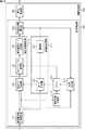
図1及び図2は、本技術を適用した計測装置の一実施の形態を示している。図1は、計測装置1の外観の構成例を示している。図2は、計測装置1の本体部11の構成例を示している。<1. Embodiment>
{Configuration example of measuring device 1}
1 and 2 show an embodiment of a measurement apparatus to which the present technology is applied. FIG. 1 shows an example of the external configuration of the
計測装置1は、スペックル方式を用いて被験者の脈拍を計測する計測装置である。スペックル方式とは、イスラエルのバル=イラン大学(BIU)のZeev Zalevsky教授によって提案されている手法であり、画像内のスペックルパターンの動き量を画像解析によって推定し、粗面の変動を計測する手法である。 The
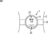
計測装置1は、本体部11とバンド12により構成され、腕時計のようにバンド12が被験者の腕(手首)2に装着されるリストバンド型の計測装置である。そして、計測装置1は、発光素子22により所定の波長の照明光を被験者の腕2の脈を含む部分である計測部位に照射した状態で、カメラ23により計測部位を撮影し、得られた画像に基づいて被験者の脈拍を計測する。 The measuring
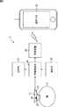
本体部11は、基板21、発光素子22、カメラ23、遮光体24、操作部25、情報処理部26、表示部27、及び、無線装置28を含むように構成される。発光素子22、カメラ23、及び、遮光体24は、基板21上に設けられている。 The
発光素子22は、例えば、LED(Light Emitting Diode)等により構成される。発光素子22は、被験者の腕2の脈拍を計測する部位である計測部位に所定の波長の照明光を照射する。 The
カメラ23は、発光素子22からの照明光が照射された被験者の計測部位を撮影し、得られた画像を情報処理部26に供給する。なお、脈拍による脈の動きは微小なため、フォーカス位置が、計測部位の表面(粗面)ではなく、カメラ23に十分近くなるように光学系が設計される。これにより、カメラ23は、計測部位のスペックルの空間像(以下、スペックル画像と称する)を撮影する。 The
遮光体24は、基板21上において発光素子22とカメラ23の間に設けられている。遮光体24は、発光素子22からの照明光が、カメラ23に直接入射されることを防止する。 The
操作部25は、例えば、ボタン、スイッチ等の各種の操作部材により構成され、本体部11の表面等に設けられる。操作部25は、計測装置1の操作に用いられ、操作内容を示す信号を情報処理部26に供給する。 The
情報処理部26は、カメラ23から供給されるスペックル画像に基づいて、被験者の脈拍を計測する処理を行う。情報処理部26は、脈拍の計測結果を表示部27及び無線装置28に供給する。 The
表示部27は、例えば、LCD(Liquid Crystal Display)等の表示装置により構成され、本体部11の表面に設けられる。表示部27は、被験者の脈拍の計測結果等を表示する。 The
無線装置28は、所定の方式の無線通信により、被験者の脈拍の計測結果を外部の装置に送信する。例えば、図2に示されるように、無線装置28は、被験者の脈拍の計測結果をスマートフォン3に送信し、スマートフォン3の画面3Aに計測結果を表示させる。なお、無線装置28の通信方式には、任意の方式を採用することができる。 The
{情報処理部26aの構成例}
図3は、計測装置1の情報処理部26の第1の実施の形態である情報処理部26aの構成例を示している。情報処理部26aは、動き検出部101及び脈拍計測部102を含むように構成される。動き検出部101は、空間周波数解析部111、複素共役計算部112、メモリ113、相互相関解析部114、及び、脈拍動き量推定部115を含むように構成される。{Configuration example of
FIG. 3 shows a configuration example of the
空間周波数解析部111は、カメラ23から供給されるスペックル画像の空間周波数分布の解析を行い、スペックル画像の空間周波数のスペクトル分布を検出する。空間周波数解析部111は、スペックル画像の空間周波数のスペクトル分布を示す空間周波数分布データを複素共役計算部112及びクロスパワースペクトル計算部121に供給する。 The spatial
複素共役計算部112は、空間周波数分布データの複素共役を計算し、得られた複素共役データをメモリ113に記憶させる。 The complex
相互相関解析部114は、現在のフレームのスペックル画像と1フレーム前のスペックル画像の相互相関解析を行う。相互相関解析部114は、クロスパワースペクトル計算部121及び相互相関マップ生成部122を含むように構成される。 The cross
クロスパワースペクトル計算部121は、現在のフレームの空間周波数分布データ、及び、1フレーム前の空間周波数分布データの複素共役データに基づいて、現在のフレームと1フレーム前のスペックル画像の同じ位置のブロック間のクロスパワースペクトルを計算する。なお、ブロックは、スペックル粒子の粒径や動きに対して十分大きいサイズに設定される。クロスパワースペクトル計算部121は、計算したクロスパワースペクトルを相互相関マップ生成部122に供給する。 Based on the spatial frequency distribution data of the current frame and the complex conjugate data of the spatial frequency distribution data of the previous frame, the cross power
相互相関マップ生成部122は、クロスパワースペクトルに対して2次元の逆離散フーリエ変換を行い、さらに正規化することにより、相互相関係数マップを生成する。相互相関係数マップは、現在のフレームのスペックル画像と1フレーム前のスペックル画像との相互相関解析の結果を表す。相互相関マップ生成部122は、生成した相互相関係数マップを脈拍動き量推定部115に供給する。 The
脈拍動き量推定部115は、相互相関係数マップに基づいて、隣接するフレームのスペックル画像の間の脈拍(脈の動き)による動き量(以下、脈拍動き量と称する)を推定する。脈拍動き量推定部115は、脈拍動き量の推定結果を脈拍計測部102に供給する。 Based on the cross-correlation coefficient map, the pulse motion
脈拍計測部102は、脈拍動き量の推定結果に基づいて、被験者の脈拍を計測する。脈拍計測部102は、被験者の脈拍の計測結果を表示部27及び無線装置28に供給する。 The
{脈拍計測処理の第1の実施の形態}
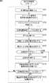
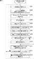
次に、図4のフローチャートを参照して、計測装置1により実行される脈拍計測処理の第1の実施の形態について説明する。{First embodiment of pulse measurement processing}
Next, a first embodiment of the pulse measurement process executed by the
ステップS1において、カメラ23は、計測部位を撮影する。具体的には、カメラ23は、図2を参照して上述したように、発光素子22により所定の波長の照明光が照射された被験者の計測部位を撮影する。そして、カメラ23は、撮影の結果得られたスペックル画像を空間周波数解析部111に供給する。 In step S1, the
ステップS2において、空間周波数解析部111は、スペックル画像の空間周波数解析を行う。例えば、空間周波数解析部111は、スペックル画像に対して2次元の離散フーリエ変換を行う。そして、空間周波数解析部111は、解析の結果得られたスペックル画像の空間周波数のスペクトル分布を示す空間周波数分布データを複素共役計算部112及びクロスパワースペクトル計算部121に供給する。 In step S2, the spatial
ステップS3において、クロスパワースペクトル計算部121は、クロスパワースペクトルを計算する。具体的には、クロスパワースペクトル計算部121は、1フレーム前の空間周波数分布データの複素共役データをメモリ113から読み出す。そして、クロスパワースペクトル計算部121は、現在のフレームの空間周波数分布データと、1フレーム前の空間周波数分布データの複素共役データとの畳み込み積分を行い、クロスパワースペクトルを計算する。 In step S3, the cross power
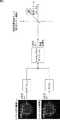
例えば、図5に示されるように、現在のnフレーム目のスペックル画像Tnの空間周波数分布データをFFT[Tn]とし、n-1フレーム目のスペックル画像Tn-1の空間周波数分布データをFFT[Tn-1]とし、空間周波数分布データFFT[Tn-1]の複素共役データをCFFT[Tn-1]とした場合、クロスパワースペクトルSは、次式(1)により算出される。For example, as shown in FIG. 5, the spatial frequency distribution data of the speckle image Tn of the current n th frame and FFT [Tn], n-1 th frame of the spatial frequency of the speckle image Tn-1 When the distribution data is FFT [Tn-1 ] and the complex conjugate data of the spatial frequency distribution data FFT [Tn-1 ] is CFFT [Tn-1 ], the cross power spectrum S is expressed by the following equation (1). Is calculated by
S=FFT[Tn]*CFFT[Tn-1] ・・・(1)S = FFT [Tn ] * CFFT [Tn-1 ] (1)
なお、式(1)の*は、畳み込み積分を示す。 In addition, * of Formula (1) shows a convolution integral.
クロスパワースペクトル計算部121は、計算したクロスパワースペクトルを相互相関マップ生成部122に供給する。 The cross power
ステップS4において、相互相関マップ生成部122は、相互相関係数マップを生成する。具体的には、相互相関マップ生成部122は、クロスパワースペクトルに対して2次元の逆離散フーリエ変換を行い、さらに正規化することにより、相互相関係数マップを生成する。 In step S4, the
図5の右端の図は、相互相関係数マップの例を示している。相互相関係数マップは、NCC(Normalized Cross-Correlation,正規化相互相関)のコスト関数の値である相互相関係数(相関値)をx軸及びy軸を持つ2次元のグラフにマッピングしたものである。この例では、2次元のグラフの各座標における相互相関係数が、等高線により表されている。 The rightmost diagram in FIG. 5 shows an example of a cross-correlation coefficient map. The cross-correlation coefficient map is a map of the cross-correlation coefficient (correlation value), which is the value of the cost function of NCC (Normalized Cross-Correlation), on a two-dimensional graph with x-axis and y-axis. It is. In this example, the cross-correlation coefficient at each coordinate of the two-dimensional graph is represented by contour lines.
相互相関マップ生成部122は、生成した相互相関係数マップを脈拍動き量推定部115に供給する。 The cross correlation
ステップS5において、脈拍動き量推定部115は、脈拍による動き量を推定する。具体的には、脈拍動き量推定部115は、相互相関係数マップにおいて相互相関係数の値が最も高くなる位置(ピーク位置)の座標を検出する。そして、脈拍動き量推定部115は、図5に示されるように、相互相関係数マップの原点と検出したピーク位置とを結ぶベクトルを、1フレーム前のスペックル画像と現在のフレームのスペックル画像との間の動きベクトルとして検出する。 In step S <b> 5, the pulse motion
ここで、脈拍(脈の動き)による計測部位の表面(粗面)の振動により、スペックル画像のスペックルパターンは平面方向に移動する。また、脈拍による計測部位の表面の振動の角度成分は、スペックルパターンの平面方向の移動量として現れる。そこで、脈拍動き量推定部115は、検出した動きベクトルのx軸方向及びy軸方向の成分Δx及びΔyを、脈拍によるスペックルパターンのx軸方向及びy軸方向の動き量(すなわち、脈拍動き量)であると推定する。 Here, the speckle pattern of the speckle image moves in the plane direction due to the vibration of the surface (rough surface) of the measurement site due to the pulse (movement of the pulse). Further, the angular component of the vibration of the surface of the measurement site due to the pulse appears as a movement amount in the plane direction of the speckle pattern. Therefore, the pulse motion
脈拍動き量推定部115は、脈拍動き量の推定結果を脈拍計測部102に供給する。脈拍計測部102は、脈拍動き量の推定結果をメモリに記憶させる。 The pulse movement
ステップS6において、脈拍計測部102は、脈拍を計測するか否かを判定する。脈拍計測部102は、例えば、脈拍を計測するのに十分な脈拍動き量の推定結果が蓄積されている場合、脈拍を計測すると判定し、処理はステップS7に進む。 In step S6, the
ステップS7において、脈拍計測部102は、脈拍を計測する。具体的には、脈拍動き量を時系列に並べたグラフを作成した場合、ほぼ同じ波形が、脈拍に同期して所定の周期で繰り返し現れる。そこで、例えば、脈拍計測部102は、直前の所定の期間内の脈拍動き量の推定結果に基づいて、その周期を検出し、検出した周期に基づいて、被験者の脈拍を計算する。脈拍計測部102は、脈拍の計測結果を表示部27及び無線装置28に供給する。 In step S7, the
そして、例えば、表示部27は、被験者の脈拍の計測結果を表示する。また、例えば、無線装置28は、所定の方式の無線通信により、被験者の脈拍の計測結果をスマートフォン3に送信し、スマートフォン3の画面3Aに計測結果を表示させる。 For example, the
その後、処理はステップS8に進む。 Thereafter, the process proceeds to step S8.
一方、ステップS6において、脈拍計測部102は、例えば、まだ脈拍を計測するのに十分な脈拍動き量の推定結果が蓄積されていない場合、まだ脈拍を計測しないと判定し、ステップS7の処理はスキップされ、処理はステップS8に進む。 On the other hand, in step S6, the
ステップS8において、複素共役計算部112は、空間周波数分布データの複素共役を計算する。すなわち、複素共役計算部112は、現在のフレームのスペックル画像の空間周波数分布データの複素共役を計算し、計算した複素共役データをメモリ113に記憶させる。このメモリ113に記憶された複素共役データが、次のフレームにおけるクロスパワースペクトルの計算に用いられる。 In step S8, the complex
その後、処理はステップS1に戻り、ステップS1以降の処理が実行される。 Thereafter, the process returns to step S1, and the processes after step S1 are executed.
以上のようにして、スペックル画像に基づいて被験者の脈拍が計測される。また、フーリエ変換を用いた正規化相互相関を類似度の関数として解析することにより、テンプレートマッチングを用いた場合に必要な探索処理の実行が不要となる。従って、脈拍動き量を高速に精度よく推定することができ、その結果、被験者の脈拍を高速に精度よく計測することができる。 As described above, the pulse of the subject is measured based on the speckle image. Further, by analyzing the normalized cross-correlation using Fourier transform as a function of similarity, it is not necessary to perform search processing that is necessary when using template matching. Therefore, the amount of pulse motion can be accurately estimated at high speed, and as a result, the pulse of the subject can be accurately measured at high speed.
ここで、図6の上側の図に示されるように、被験者の腕2が動いた場合、発光素子22による照明光の照射位置が変動し、計測部位が変動する。また、図6の下側の図に示されるように、スペックル画像は露光時間中のカメラ23の露光量を積分して撮影されるため、体動によりスペックルパターンが大きく動くと、スペックル画像内に動きボケが発生する。 Here, as shown in the upper diagram of FIG. 6, when the subject's
そして、動きボケ発生時に、上述したように、隣接するフレーム間の相互相関解析を行った場合、マッチング精度が低下する。その結果、図7に示されるように、相互相関係数マップ上に、脈拍により生じる動き量とは異なる位置に疑似ピークが発生し、脈拍動き量の推定誤差が発生する。 Then, as described above, when cross-correlation analysis between adjacent frames is performed when motion blur occurs, matching accuracy decreases. As a result, as shown in FIG. 7, a pseudo peak occurs at a position different from the amount of motion caused by the pulse on the cross-correlation coefficient map, and an estimation error of the pulse motion amount occurs.
一方、光学系を工夫することにより、体動によるスペックルパターンの移動量を抑制することが可能であるが、一方で、小さな振動の計測が困難になるというトレードオフが発生する。そのため、動きボケの影響を受けずに、微小な動きから大きな動きまで広いダイナミックレンジでスペックルパターンの動きを精度よく検出する技術が求められる。 On the other hand, by devising the optical system, it is possible to suppress the amount of movement of the speckle pattern due to body movement, but on the other hand, a trade-off occurs that makes it difficult to measure small vibrations. Therefore, there is a need for a technique for accurately detecting speckle pattern motion in a wide dynamic range from minute motion to large motion without being affected by motion blur.
{情報処理部26bの構成例}
図8は、計測装置1の情報処理部26の第2の実施の形態である情報処理部26bの構成例を示している。情報処理部26bは、情報処理部26aと比較して、スペックル画像の動きボケの影響を低減し、脈拍動き量の推定精度を高め、その結果、脈拍の計測精度を向上させるようにするものである。なお、図中、図3と対応する部分には同じ符号を付してあり、その説明は適宜省略する。{Configuration example of
FIG. 8 shows a configuration example of an
情報処理部26bを図3の情報処理部26aと比較すると、動き検出部101の代わりに動き検出部201が設けられている点が異なる。動き検出部201は、動き検出部101と比較すると、体動動き量推定部211及び状態判定部213が追加され、脈拍動き量推定部115の代わりに、脈拍動き量推定部212が追加されている点が異なる。 3 is different from the
体動動き量推定部211は、各フレームのスペックル画像内の被験者の体動による動き量(以下、体動動き量と称する)及び体動方向を推定する。体動動き量推定部211は、MTF計算部221及び推定部222を含むように構成される。 The body motion motion
MTF計算部221は、計測部位がほぼ静止している場合の空間周波数分布データ(以下、静止時空間周波数分布データと称する)をメモリ113から読み出す。そして、MTF計算部221は、空間周波数解析部111から供給される空間周波数分布データ、及び、静止時空間周波数分布データに基づいて、スペックル画像の動きボケの特性を表すMTF(Modulation Transfer Function:伝達関数)を計算する。MTF計算部221は、MTFの計算結果を推定部222に供給する。 The
推定部222は、MTF計算部221により計算されたMTFに基づいて、体動動き量及び体動方向を推定する。推定部222は、体動動き量及び体動方向の推定結果を、脈拍動き量推定部212及び状態判定部213に供給する。 The
脈拍動き量推定部212は、相互相関係数マップ、並びに、体動動き量及び体動方向の推定結果に基づいて、脈拍動き量を推定する。脈拍動き量推定部115は、脈拍動き量の推定結果を脈拍計測部102に供給する。 The pulse motion
状態判定部213は、体動動き量の推定結果に基づいて、計測部位がほぼ静止しているか否かを判定する。また、状態判定部213は、計測部位がほぼ静止していると判定した場合、メモリ113に記憶されている静止時空間周波数分布データを、現在のフレームの空間周波数分布データに更新する。 The
{脈拍計測処理の第2の実施の形態}
次に、図9のフローチャートを参照して、計測装置1により実行される脈拍計測処理の第2の実施の形態について説明する。{Second Embodiment of Pulse Measurement Processing}
Next, a second embodiment of the pulse measurement process executed by the
ステップS101において、図4のステップS1の処理と同様に、計測部位が撮影される。 In step S101, the measurement region is imaged in the same manner as in step S1 of FIG.
ステップS102において、図4のステップS2の処理と同様に、スペックル画像の空間周波数解析が行われる。空間周波数解析部111は、解析の結果得られた空間周波数分布データを、複素共役計算部112、クロスパワースペクトル計算部121、状態判定部213、及び、MTF計算部221に供給する。 In step S102, the spatial frequency analysis of the speckle image is performed as in the process of step S2 of FIG. The spatial
ステップS103において、図4のステップS3の処理と同様に、クロスパワースペクトルが計算される。 In step S103, the cross power spectrum is calculated in the same manner as in step S3 of FIG.
ステップS104において、図4のステップS4の処理と同様に、相互相関係数マップが生成される。 In step S104, a cross-correlation coefficient map is generated in the same manner as in step S4 in FIG.
ステップS105において、MTF計算部221は、MTFを計算する。 In step S105, the
ステップS106において、推定部222は、体動による動き量を推定する。 In step S106, the
ステップS107において、脈拍動き量推定部212は、脈拍による動き量を推定する。 In step S107, the pulse motion
ここで、図10乃至図13を参照して、ステップS105乃至S107の処理の詳細について説明する。 Here, with reference to FIG. 10 thru | or FIG. 13, the detail of the process of step S105 thru | or S107 is demonstrated.
上述したように、隣接するフレーム間の相互相関を用いて脈拍動き量を推定する場合、被験者の体動により発生する動きボケが誤差の要因となる。 As described above, when the pulse motion amount is estimated using the cross-correlation between adjacent frames, motion blur caused by the body motion of the subject causes an error.
一方、動きボケを利用して、被写体の動き量を推定する手法が広く知られている。ここで、図10を参照して、動きボケの発生原理について説明する。 On the other hand, a technique for estimating the amount of motion of a subject using motion blur is widely known. Here, the generation principle of motion blur will be described with reference to FIG.
スペックル画像の動きボケ量を示す点拡がり関数(PSF:Point Spread Function)は、カメラ23のレンズ特性ClensによるPSF hopt(Clens)(x, y)、動き量v及びカメラ23の露光時間TexpによるPSF hopt(v,Texp) (x, y)とを畳み込み積分することにより導出される。動き量vは、露光時間内の被験者の体動により発生するスペックルパターンの動き量(体動動き量)に相当する。The point spread function (PSF) indicating the amount of motion blur of the speckle image is PSF hopt (Clens) (x, y) based on the lens characteristic Clens of the
この動きボケ量を示すPSFをh(v,Clens,Texp)(x, y)とすると、静止時のスペックル画像z1にPSF h(v,Clens,Texp)(x, y)を畳み込み積分することにより、動きボケが発生したスペックル画像z2が得られる。これを数式で表すと、次式(2)及び(3)のようになる。When PSF indicating the amount of motion blur is h(v,Clens,Texp) (x, y), PSF h(v,Clens,Texp) (x, y) is convolved with the speckle image z1 at rest. Thus, a speckle image z2 in which motion blur has occurred is obtained. This is expressed by the following equations (2) and (3).

この原理を応用して、動きボケが発生したスペックル画像からPSF h(v,Clens,Texp)(x, y)を推定し、推定したPSF h(v,Clens,Texp)(x, y)にカメラ23の特性(レンズ特性、露光時間)を適用することにより、動き量vを求めることができる。By applying this principle, PSF h(v,Clens,Texp) (x, y) is estimated from speckle images with motion blur, and the estimated PSF h(v,Clens,Texp) (x, y) By applying the characteristics (lens characteristics, exposure time) of the
一方、スペックルの空間像は、テクスチャ(空間周波数分布)を保ったまま空間内を水平にシフトする。これに着目し、体動動き量推定部211は、PSFを直接求めるのではなく、動きボケの特性を表すMTFを求めることにより、体動動き量を推定する。なお、ここでいうスペックルの空間像とは、実世界の空間上の光学像のことであり、カメラ23で撮影したスペックル画像とは異なる点に注意が必要である。 On the other hand, the aerial image of speckle shifts horizontally in the space while maintaining the texture (spatial frequency distribution). Focusing on this, the body motion
図11は、静止時のスペックル画像(上側)とその空間周波数分布(下側)の例を示している。図12は、体動時のスペックル画像(上側)とその空間周波数分布(下側)の例を示している。 FIG. 11 shows an example of a speckle image (upper side) and its spatial frequency distribution (lower side) at rest. FIG. 12 shows an example of a speckle image (upper side) and its spatial frequency distribution (lower side) during body movement.
静止時のスペックル画像は、白色ノイズのようなテクスチャを有しており、フーリエ変換すると、空間周波数の全帯域にわたりほぼ一様にスペクトルが分布する。これは、ガウシアン分布をフーリエ変換した数式からも原理的に説明がつく。 The speckle image at rest has a texture such as white noise, and when Fourier transform is performed, the spectrum is distributed almost uniformly over the entire spatial frequency band. This can be explained in principle from mathematical expressions obtained by Fourier transform of the Gaussian distribution.
一方、体動時のスペックル画像の空間周波数分布においては、体動方向について高域成分が減少し、低域成分が増加する。一方、体動方向に垂直な方向の空間周波数分布は、静止時からほとんど変化しない。また、体動(動き量v)が大きくなるほど、MTFの劣化が空間周波数の低域側にシフトすることが分かっている。従って、体動方向についてのみMTFの空間周波数の低域の値が低下する。 On the other hand, in the spatial frequency distribution of the speckle image during body motion, the high frequency component decreases and the low frequency component increases in the body motion direction. On the other hand, the spatial frequency distribution in the direction perpendicular to the body movement direction hardly changes from when stationary. It has also been found that as the body motion (movement amount v) increases, the MTF degradation shifts to the lower side of the spatial frequency. Therefore, the low frequency value of the MTF spatial frequency is reduced only in the body movement direction.
そこで、体動動き量推定部211は、MTFの値が所定の閾値以下となる空間周波数を検出することで、体動動き量(符号なしのベクトル)を推定する。具体的には、上述した式(2)を、フーリエ変換により空間周波数ドメインの関数に変換すると、次式(4)となる。 Therefore, the body motion
なお、Z1は、静止時のスペックル画像z1をフーリエ変換したもの、Z2は体動時のスペックル画像z2をフーリエ変換したもの、ωxはx軸方向の角周波数、ωyはy軸方向の角周波数である。また、H(v,Clens,Texp) (ωx, ωy)は、動きボケを表すPSF h(v,Clens,Texp)(x, y)をフーリエ変換したものであり、動きボケの特性を表すMTFの空間周波数毎のコントラスト応答を示す。ここで、式(4)のスペクトル特性に着目すると、式(4)は次式(5)のように変形できる。Z1 is the Fourier transform of the speckle image z1 at rest, Z2 is the Fourier transform of the speckle image z2 at body motion, ωx is the angular frequency in the x-axis direction, ωy is the y-axis direction Is the angular frequency. H(v,Clens,Texp) (ωx , ωy ) is a Fourier transform of PSF h(v,Clens,Texp) (x, y) representing motion blur. The contrast response for every spatial frequency of MTF to represent is shown. Here, paying attention to the spectrum characteristic of the formula (4), the formula (4) can be transformed as the following formula (5).
すなわち、動きボケの特性を表すMTFの空間周波数特性を示す|H(v,Clens,Texp)(ωx, ωy)|は、体動時の空間周波数分布と静止時空間周波数分布との空間周波数毎の強度の比により表される。この|H(v,Clens,Texp)(ωx, ωy)|の値が所定の閾値以下となる空間周波数を検出することにより、大まかな体動動き量を推定することができる。That is, | H(v,Clens,Texp) (ωx , ωy ) |, which represents the spatial frequency characteristics of MTF, which represents the motion blur characteristics, is the spatial frequency distribution between body motion and stationary spatial frequency distribution. It is represented by the ratio of intensity for each frequency. By detecting a spatial frequency at which the value of | H(v,Clens,Texp) (ωx , ωy ) | is equal to or less than a predetermined threshold, a rough body motion motion amount can be estimated.
さらに、式(5)を変形した次式(6)の|Hmot(v,Texp)(ωx, ωy)|を用いることにより、より詳細に体動動き量を推定することができる。Further, by using | Hmot (v,Texp) (ωx , ωy ) | in the following equation (6) obtainedbymodifying equation (5), it is possible to estimate the amount of body motion motion in more detail.
なお、|Hmot(v,Texp)(ωx, ωy)|は、動き量v及びカメラ23の露光時間TexpによるPSF hmot(v,Texp)をフーリエ変換したものであり、|Hopt(Clens)(ωx, ωy)|は、カメラ23のレンズ特性ClensによるPSF hopt(Clens)(x, y)をフーリエ変換したものである。従って、|Hmot(v,Texp)(ωx, ωy)|は、|H(v,Clens,Texp)(ωx, ωy)|からレンズによるボケの影響を除去したものとなる。| Hmot (v,Texp) (ωx , ωy ) | is a Fourier transform of PSF hmot (v,Texp) based on the motion amount v and the exposure time Texp of the
ステップS105において、MTF計算部221は、静止時のスペックル画像の空間周波数分布データ(静止時空間周波数分布データ)をメモリ113から読み出す。この静止時空間周波数分布データは、式(5)及び式(6)のZ1(ωx, ωy)に相当する。In step S <b> 105, the
そして、MTF計算部221は、例えば、動きボケの特性を表すMTFの空間周波数特性として、式(5)に基づいて、|H(v,Clens,Texp) (ωx, ωy)|を計算するか、式(6)に基づいて、|Hmot(v,Texp)(ωx, ωy)|を計算する。なお、式(5)及び式(6)のZ2(ωx, ωy)には、現在のフレームのスペクトル画像の空間周波数分布データが用いられる。Then, the
MTF計算部221は、|H(v,Clens,Texp)(ωx, ωy)|又は|Hmot(v,Texp)(ωx, ωy)|の計算結果を推定部222に供給する。The
なお、以下、MTF計算部221により計算された|H(v,Clens,Texp)(ωx, ωy)|又は|Hmot(v,Texp)(ωx, ωy)|をMTF空間周波数特性と総称する。Hereinafter, | H(v,Clens,Texp) (ωx , ωy ) | or | Hmot (v,Texp) (ωx , ωy ) | calculated by the
ステップS106において、推定部222は、MTF計算部221により計算されたMTF空間周波数特性の値が所定の閾値以下となる空間周波数を検出する。そして、推定部222は、検出結果に基づいて、体動動き量及び体動の方向を推定する。 In step S106, the
具体的には、被写体の動き量に対して、MTF空間周波数特性(|H(v,Clens,Texp)(ωx, ωy)|又は|Hmot(v,Texp)(ωx, ωy)|)の各空間周波数の値がどの程度劣化(低下)するかを示すデータが、カメラ23のパラメータに基づいて事前に見積もられる。そして、推定部222は、そのデータを保持しており、MTF空間周波数特性の値が所定の閾値以下となる空間周波数に基づいて、体動動き量を推定する。また、推定部222は、MTF空間周波数特性の値が所定の閾値以下となる領域を算出することで体動方向を推定する。Specifically, the MTF spatial frequency characteristics (| H(v,Clens,Texp) (ωx , ωy ) | or | Hmot (v,Texp) (ωx , ωy) ) |) The data indicating how much the value of each spatial frequency deteriorates (decreases) is estimated in advance based on the parameters of the
推定部222は、体動動き量及び体動方向の推定結果を、脈拍動き量推定部212及び状態判定部213に供給する。 The
ステップS107において、例えば、脈拍動き量推定部115は、相互相関係数マップにおいて相互相関係数の値が所定の閾値以上となるピーク位置を検出する。次に、脈拍動き量推定部115は、相互相関係数マップの原点と検出したピーク位置とを結ぶ動きベクトルを検出する。次に、脈拍動き量推定部115は、検出した各動きベクトルのうち、推定部222により推定された体動動き量及び体動方向に近い動きベクトルを除外する。そして、脈拍動き量推定部115は、残った動きベクトルのうちから1つを選択し、選択した動きベクトルのx軸方向及びy軸方向の成分を、x軸方向及びy軸方向の脈拍動き量であると推定する。 In step S107, for example, the pulse motion
例えば、図13の右側の相互相関係数マップの例では、3つのピークP1乃至P3が現れている。一方、図13の左側の図に示されるように、体動方向はやや左斜め上方向であり、相互相関係数マップの原点とピークP1乃至P3とを結ぶ各動きベクトルのうち、原点とピークP3を結ぶ動きベクトルが候補から除外される。すなわち、ピークP3が疑似ピークとして除外される。そして、脈拍動き量推定部115は、原点とピークP1を結ぶ動きベクトル、及び、原点とピークP2を結ぶ動きベクトルのうちいすれか一方を選択する。例えば、脈拍動き量推定部115は、ピークP1とピークP2のうち値が大きい方のピークを選択し、原点と選択したピークとを結ぶ動きベクトルに基づいて、脈拍動き量を推定する。 For example, in the example of the cross-correlation coefficient map on the right side of FIG. 13, three peaks P1 to P3 appear. On the other hand, as shown in the diagram on the left side of FIG. 13, the body motion direction is slightly upward to the left, and among the motion vectors connecting the origin of the cross-correlation coefficient map and the peaks P1 to P3, the origin and the peak The motion vector connecting P3 is excluded from the candidates. That is, the peak P3 is excluded as a pseudo peak. Then, the pulse motion
なお、例えば、体動動き量の推定精度が担保されない場合、例えば、脈拍動き量の推定に用いるピーク候補を検出する領域(以下、ピーク検出領域と称する)を限定するようにしてもよい。例えば、相互相関係数マップの原点を中心にして、体動方向の幅が体動動き量の2倍の領域(例えば、図13の左側の図の2本の斜め方向の線で挟まれた領域と同様の形状の領域)を、ピーク検出領域に設定するようにしてもよい。 For example, when the estimation accuracy of the body motion amount is not ensured, for example, a region for detecting a peak candidate used for estimation of the pulse motion amount (hereinafter referred to as a peak detection region) may be limited. For example, with the center of the cross-correlation coefficient map as the center, the body motion direction width is twice the body motion motion amount (for example, sandwiched between two diagonal lines in the left diagram of FIG. 13 An area having the same shape as the area) may be set as the peak detection area.
このように、ピーク検出領域を限定することにより、疑似ピークをピーク検出領域から確実に除外することができ、脈拍動き量の推定において体動に対するロバスト性を高めることができる。 In this way, by limiting the peak detection region, the pseudo peak can be surely excluded from the peak detection region, and robustness against body movement can be improved in estimating the pulse motion amount.
或いは、例えば、脈拍動き量推定部115は、MTF空間周波数特性の劣化度合いに応じて、動き候補重みマップを生成する。例えば、重みは、0.0〜1.0の範囲の値を設定する。 Alternatively, for example, the pulse motion
脈拍動き量推定部115は、相互相関係数マップの各座標の相互相関係数に、動き候補重みマップの各座標の重みを掛け合わせて、相互相関係数マップを補正する。そして、脈拍動き量推定部115は、例えば、補正後の相互相関係数マップにおいて、原点と相互相関係数の値が最も高くなるピーク位置と結ぶ動きベクトルに基づいて、脈拍動き量を推定する。 The pulse motion
脈拍動き量推定部115は、脈拍動き量の推定結果を脈拍計測部102に供給する。脈拍計測部102は、脈拍動き量の推定結果を示すデータを図示せぬメモリに記憶させる。 The pulse movement
そして、ステップS108乃至S110において、図4のステップS6乃至S8と同様の処理が実行される。 In steps S108 to S110, processing similar to that in steps S6 to S8 in FIG. 4 is executed.
ステップS111において、状態判定部213は、計測部位が静止しているか否かを判定する。例えば、状態判定部213は、推定部222により推定された体動動き量が所定の閾値未満である場合、計測部位が静止していると判定し、処理はステップS112に進む。 In step S111, the
なお、この閾値は、例えば、この閾値未満の体動動き量により発生する動きボケが脈拍動き量の推定結果に影響を与えない程度に、十分に小さい値に設定される。 Note that this threshold is set to a sufficiently small value, for example, such that motion blur caused by a body motion amount less than this threshold does not affect the estimation result of the pulse motion amount.
ステップS112において、状態判定部213は、静止時の空間周波数分布データを更新する。すなわち、状態判定部213は、現在のフレームのスペックル画像の空間周波数分布データをメモリ113に記憶させる。また、状態判定部213は、現在の静止時空間周波数分布データをメモリ113から削除する。これにより、現在のフレームのスペックル画像の空間周波数分布データが、次に使用する静止時空間周波数分布データに設定される。 In step S112, the
脈拍の計測中に外光の状態や計測部位が変動することが想定されるため、このように静止状態が検出される度に静止時空間周波数分布データを更新することにより、体動動き量の推定精度が向上する。 Since it is assumed that the state of the external light and the measurement site fluctuate during pulse measurement, updating the stationary spatio-temporal frequency distribution data every time a stationary state is detected in this way, The estimation accuracy is improved.
なお、静止時空間周波数分布データは、MTF空間周波数特性の算出のみに用いられるため、状態判定部213は、各空間周波数のスペクトル成分の値のみをメモリ113に記憶させればよい。従って、実数データのみ記憶させればよいため、複素数データも記憶させる場合と比較して、約半分の記憶容量で済む。 Since the stationary spatial frequency distribution data is used only for calculating the MTF spatial frequency characteristics, the
その後、処理はステップS101に戻り、ステップS101以降の処理が実行される。 Thereafter, the process returns to step S101, and the processes after step S101 are executed.
一方、ステップS111において、状態判定部213は、推定部222により推定された体動動き量が所定の閾値以上である場合、計測部位が静止していないと判定し、処理はステップS101に戻る。その後、ステップS101以降の処理が実行される。 On the other hand, in step S111, the
以上のようにして、動きボケの影響を低減し、脈拍動き量の推定精度を高め、脈拍の計測精度を向上させることができる。 As described above, the influence of motion blur can be reduced, the estimation accuracy of the pulse motion amount can be increased, and the pulse measurement accuracy can be improved.
また、体動が大きいほど、体動動き量を検出しやすくなり、相互相関解析による動き推定の弱点を補うことができる。 In addition, the greater the body motion, the easier it is to detect the amount of body motion and compensate for the weakness of motion estimation by cross-correlation analysis.
さらに、カメラ23のレンズのパラメータや露光時間を、カメラ23のイメージセンサの仕様にフィードバックすることが可能である。従って、アプリケーションに合わせて、イメージセンサと信号処理の双方から、脈拍動き量の推定精度の改善を図ることができる。 Furthermore, the lens parameters of the
{情報処理部26cの構成例}
図14は、計測装置1の情報処理部26の第3の実施の形態である情報処理部26cの構成例を示している。なお、図中、図8と対応する部分には同じ符号を付してあり、その説明は適宜省略する。{Configuration example of
FIG. 14 illustrates a configuration example of an
情報処理部26cを図8の情報処理部26bと比較すると、動き検出部201の代わりに動き検出部301が設けられている点が異なる。動き検出部301は、動き検出部201と比較して、動きボケ除去部311が追加されている点が異なる。 When the
動きボケ除去部311は、MTF計算部221から供給されるMTF空間周波数特性に基づいて、空間周波数分布データから動きボケ成分を除去する。動きボケ除去部311は、動きボケ成分を除去した空間周波数分布データを、複素共役計算部112、クロスパワースペクトル計算部121、及び、状態判定部213に供給する。 The motion
{脈拍計測処理の第2の実施の形態}
次に、図15のフローチャートを参照して、計測装置1により実行される脈拍計測処理の第3の実施の形態について説明する。{Second Embodiment of Pulse Measurement Processing}
Next, a third embodiment of the pulse measurement process executed by the
ステップS201乃至S203において、図9のステップS101乃至S103と同様の処理が実行される。 In steps S201 to S203, processing similar to that in steps S101 to S103 in FIG. 9 is executed.
ステップS204において、図9のステップS105の処理と同様に、MTF空間周波数特性が計算される。MTF空間周波数特性の計算結果は、MTF計算部221から推定部222及び動きボケ除去部311に供給される。 In step S204, the MTF spatial frequency characteristics are calculated in the same manner as in step S105 of FIG. The calculation result of the MTF spatial frequency characteristic is supplied from the
ステップS205において、動きボケ除去部311は、動きボケを除去する。具体的には、動きボケ除去部311は、MTF空間周波数特性(|H(v,Clens,Texp)(ωx, ωy)|又は|Hmot(v,Texp)(ωx, ωy)|)の各空間周波数の値の逆数を計算する。そして、動きボケ除去部311は、現在のフレームのスペックル画像の空間周波数分布データと、MTF空間周波数特性の逆数との畳み込み積分を行う。すなわち、現在のフレームのスペックル画像の空間周波数分布データの各空間周波数の強度に、MTF空間周波数特性の各空間周波数の値の逆数であるゲインが掛け合わされる。これにより、空間周波数分布データから動きボケ成分が除去される。In step S205, the motion
なお、各空間周波数のゲインは、大きくなりすぎるとアーチファクトの発生原因となるため、MTF空間周波数特性の完全な逆数ではなく、適宜調整するようにしてもよい。 It should be noted that if the gain of each spatial frequency becomes too large, artifacts are generated, and therefore, it may be adjusted as appropriate instead of the complete reciprocal of the MTF spatial frequency characteristics.
動きボケ除去部311は、動きボケ成分を除去した空間周波数分布データを、複素共役計算部112、クロスパワースペクトル計算部121、及び、状態判定部213に供給する。 The motion
ステップS206において、上述した図4のステップS4の処理と同様に、相互相関係数マップが生成される。ただし、図4のステップS4の処理と異なり、動きボケ成分が除去された空間周波数分布データに基づいて、相互相関係数マップが生成される。従って、相互相関係数マップの疑似ピークの発生を抑制することができ、脈拍動き量の推定精度が向上する。また、疑似ピークの発生が抑制されることにより、推定部222の処理の負荷を軽減することができる。 In step S206, a cross-correlation coefficient map is generated in the same manner as in step S4 in FIG. However, unlike the process of step S4 in FIG. 4, a cross-correlation coefficient map is generated based on the spatial frequency distribution data from which motion blur components are removed. Therefore, the occurrence of a pseudo peak in the cross correlation coefficient map can be suppressed, and the estimation accuracy of the pulse motion amount is improved. Further, by suppressing the occurrence of the pseudo peak, the processing load of the
その後、ステップS207乃至S210において、図9のステップS106乃至S109と同様の処理が実行される。 Thereafter, in steps S207 to S210, processing similar to that in steps S106 to S109 in FIG. 9 is executed.
ステップS211において、図4のステップS8の処理と同様に、空間周波数分布データの複素共役が計算される。ただし、図4のステップS8の処理と異なり、動きボケ成分が除去された空間周波数分布データの複素共役が計算される。そして、動きボケ成分が除去された空間周波数分布データが、次のフレームにおけるクロスパワースペクトルの計算に用いられる。 In step S211, the complex conjugate of the spatial frequency distribution data is calculated in the same manner as in step S8 of FIG. However, unlike the process of step S8 in FIG. 4, the complex conjugate of the spatial frequency distribution data from which the motion blur component is removed is calculated. Then, the spatial frequency distribution data from which the motion blur component is removed is used for calculation of the cross power spectrum in the next frame.
ステップS212において、図9のステップS111の処理と同様に、計測部位が静止しているか否かが判定される。計測部位が静止していると判定された場合、処理はステップS213に進む。 In step S212, whether or not the measurement site is stationary is determined in the same manner as in step S111 in FIG. If it is determined that the measurement site is stationary, the process proceeds to step S213.
ステップS213において、図9のステップS112の処理と同様に、静止時の空間周波数分布データが更新される。ただし、図9のステップS111の処理と異なり、動きボケ成分が除去された空間周波数分布データにより、静止時の空間周波数分布データが更新される。 In step S213, the spatial frequency distribution data at rest is updated as in the process of step S112 of FIG. However, unlike the process of step S111 in FIG. 9, the spatial frequency distribution data at rest is updated with the spatial frequency distribution data from which motion blur components are removed.
その後、処理はステップS201に戻り、ステップS201以降の処理が実行される。 Thereafter, the process returns to step S201, and the processes after step S201 are executed.
一方、ステップS212において、計測部位が静止していないと判定された場合、処理はステップS201に戻り、ステップS201以降の処理が実行される。 On the other hand, if it is determined in step S212 that the measurement site is not stationary, the process returns to step S201, and the processes after step S201 are executed.
以上のようにして、空間周波数分布データから動きボケ成分が除去されることにより、脈拍動き量の推定精度、及び、脈拍の計測精度が向上する。 As described above, the motion blur component is removed from the spatial frequency distribution data, thereby improving the estimation accuracy of the pulse motion amount and the measurement accuracy of the pulse.
<2.変形例>
以下、上述した本技術の実施の形態の変形例について説明する。<2. Modification>
Hereinafter, modifications of the above-described embodiment of the present technology will be described.
以上の説明では、相互相関解析を用いて脈拍動き量を推定する例を示したが、本技術は、例えば、テンプレートマッチングを用いて脈拍動き量を推定する場合にも適用することができる。 In the above description, an example in which the pulse motion amount is estimated using cross-correlation analysis has been described, but the present technology can also be applied to the case where the pulse motion amount is estimated using template matching, for example.
また、相互相関解析の方法は、上述した方法に限定されるものではなく、他の方法を用いることも可能である。 The method of cross-correlation analysis is not limited to the method described above, and other methods can be used.
さらに、例えば、状態判定部213が、相互相関係数マップをパターン解析し、最新のフレームのスペックル画像の自己相関係数マップと類似している場合、計測部位が静止していると判定するようにしてもよい。 Furthermore, for example, the
また、例えば、体動動き量推定部211は、スペックル画像の階調値の頻度ヒストグラムを生成し、ヒストグラムの平均値や分散値の揺らぎに基づいて、ボケ変化(=コントラスト変化)を求めることにより、体動動き量を推定するようにしてもよい。 Also, for example, the body motion
さらに、隣接するフレーム間ではなく、例えば、2以上離れたフレーム間で相互相関解析を行い、その解析結果に基づいて、脈拍動き量を推定するようにしてもよい。 Furthermore, for example, cross-correlation analysis may be performed not between adjacent frames but between two or more distant frames, and the pulse motion amount may be estimated based on the analysis result.
また、本技術は、腕以外の計測部位(例えば、指、耳たぶ等)において脈拍を計測する場合にも適用することができる。 The present technology can also be applied to the case where the pulse is measured at a measurement site other than the arm (for example, finger, earlobe, etc.).
さらに、本技術は、脈拍の計測処理以外にも、スペックル画像のスペックルパターンの動き量の推定を含む処理に適用することができる。 Furthermore, the present technology can be applied to processing including estimation of a motion amount of a speckle pattern of a speckle image in addition to the pulse measurement processing.
また、本技術は、スペックル画像以外にも、細かな粒子がほぼ一様に映っている画像の動き量を推定する場合にも適用することができる。 In addition to the speckle image, the present technology can also be applied to the case of estimating the motion amount of an image in which fine particles are reflected almost uniformly.
{コンピュータの構成例}
上述した一連の処理は、ハードウエアにより実行することもできるし、ソフトウエアにより実行することもできる。一連の処理をソフトウエアにより実行する場合には、そのソフトウエアを構成するプログラムが、コンピュータにインストールされる。ここで、コンピュータには、専用のハードウエアに組み込まれているコンピュータや、各種のプログラムをインストールすることで、各種の機能を実行することが可能な、例えば汎用のパーソナルコンピュータなどが含まれる。{Example of computer configuration}
The series of processes described above can be executed by hardware or can be executed by software. When a series of processing is executed by software, a program constituting the software is installed in the computer. Here, the computer includes, for example, a general-purpose personal computer capable of executing various functions by installing various programs by installing a computer incorporated in dedicated hardware.
図16は、上述した一連の処理をプログラムにより実行するコンピュータのハードウエアの構成例を示すブロック図である。 FIG. 16 is a block diagram illustrating a hardware configuration example of a computer that executes the above-described series of processing by a program.
コンピュータにおいて、CPU(Central Processing Unit)501,ROM(Read Only Memory)502,RAM(Random Access Memory)503は、バス504により相互に接続されている。 In a computer, a CPU (Central Processing Unit) 501, a ROM (Read Only Memory) 502, and a RAM (Random Access Memory) 503 are connected to each other by a
バス504には、さらに、入出力インタフェース505が接続されている。入出力インタフェース505には、入力部506、出力部507、記憶部508、通信部509、及びドライブ510が接続されている。 An input /
入力部506は、キーボード、マウス、マイクロフォンなどよりなる。出力部507は、ディスプレイ、スピーカなどよりなる。記憶部508は、ハードディスクや不揮発性のメモリなどよりなる。通信部509は、ネットワークインタフェースなどよりなる。ドライブ510は、磁気ディスク、光ディスク、光磁気ディスク、又は半導体メモリなどのリムーバブルメディア511を駆動する。 The
以上のように構成されるコンピュータでは、CPU501が、例えば、記憶部508に記憶されているプログラムを、入出力インタフェース505及びバス504を介して、RAM503にロードして実行することにより、上述した一連の処理が行われる。 In the computer configured as described above, the
コンピュータ(CPU501)が実行するプログラムは、例えば、パッケージメディア等としてのリムーバブルメディア511に記録して提供することができる。また、プログラムは、ローカルエリアネットワーク、インターネット、デジタル衛星放送といった、有線または無線の伝送媒体を介して提供することができる。 The program executed by the computer (CPU 501) can be provided by being recorded on a
コンピュータでは、プログラムは、リムーバブルメディア511をドライブ510に装着することにより、入出力インタフェース505を介して、記憶部508にインストールすることができる。また、プログラムは、有線または無線の伝送媒体を介して、通信部509で受信し、記憶部508にインストールすることができる。その他、プログラムは、ROM502や記憶部508に、あらかじめインストールしておくことができる。 In the computer, the program can be installed in the
なお、コンピュータが実行するプログラムは、本明細書で説明する順序に沿って時系列に処理が行われるプログラムであっても良いし、並列に、あるいは呼び出しが行われたとき等の必要なタイミングで処理が行われるプログラムであっても良い。 The program executed by the computer may be a program that is processed in time series in the order described in this specification, or in parallel or at a necessary timing such as when a call is made. It may be a program for processing.
また、本明細書において、システムとは、複数の構成要素(装置、モジュール(部品)等)の集合を意味し、すべての構成要素が同一筐体中にあるか否かは問わない。したがって、別個の筐体に収納され、ネットワークを介して接続されている複数の装置、及び、1つの筐体の中に複数のモジュールが収納されている1つの装置は、いずれも、システムである。 In this specification, the system means a set of a plurality of components (devices, modules (parts), etc.), and it does not matter whether all the components are in the same housing. Accordingly, a plurality of devices housed in separate housings and connected via a network and a single device housing a plurality of modules in one housing are all systems. .
さらに、本技術の実施の形態は、上述した実施の形態に限定されるものではなく、本技術の要旨を逸脱しない範囲において種々の変更が可能である。 Furthermore, the embodiments of the present technology are not limited to the above-described embodiments, and various modifications can be made without departing from the gist of the present technology.
例えば、本技術は、1つの機能をネットワークを介して複数の装置で分担、共同して処理するクラウドコンピューティングの構成をとることができる。 For example, the present technology can take a configuration of cloud computing in which one function is shared by a plurality of devices via a network and is jointly processed.
また、上述のフローチャートで説明した各ステップは、1つの装置で実行する他、複数の装置で分担して実行することができる。 In addition, each step described in the above flowchart can be executed by being shared by a plurality of apparatuses in addition to being executed by one apparatus.
さらに、1つのステップに複数の処理が含まれる場合には、その1つのステップに含まれる複数の処理は、1つの装置で実行する他、複数の装置で分担して実行することができる。 Furthermore, when a plurality of processes are included in one step, the plurality of processes included in the one step can be executed by being shared by a plurality of apparatuses in addition to being executed by one apparatus.
また、本明細書に記載された効果はあくまで例示であって限定されるものではなく、他の効果があってもよい。 Moreover, the effect described in this specification is an illustration to the last, and is not limited, There may exist another effect.
さらに、本技術の実施の形態は、上述した実施の形態に限定されるものではなく、本技術の要旨を逸脱しない範囲において種々の変更が可能である。 Furthermore, the embodiments of the present technology are not limited to the above-described embodiments, and various modifications can be made without departing from the gist of the present technology.
また、例えば、本技術は以下のような構成も取ることができる。 For example, this technique can also take the following structures.
(1)
第1の画像と前記第1の画像より前に前記第1の画像と同じ被写体を撮影した第2の画像との相互相関解析を行う相互相関解析部と、
前記第1の画像の動きボケに対応する第1の動き量を推定する第1の動き推定部と、
前記相互相関解析の結果、及び、前記第1の動き量の推定結果に基づいて、前記第1の動き量とは異なる、前記第1の画像と前記第2の画像との間の第2の動き量を推定する第2の動き推定部と
を備える情報処理装置。
(2)
前記第2の動き推定部は、前記相互相関解析の結果に基づいて動きベクトルを検出することにより、前記第2の動き量を推定するとともに、前記第1の動き量の推定結果に基づいて、前記動きベクトルを検出する領域を限定する
前記(1)に記載の情報処理装置。
(3)
前記第1の画像の第1の空間周波数分布、及び、前記第2の画像の第2の空間周波数分布を解析する空間周波数解析部を
さらに備え、
前記相互相関解析部は、前記第1の空間周波数分布及び前記第2の空間周波数分布に基づいて、前記第1の画像と前記第2の画像との相互相関解析を行う
前記(1)又は(2)に記載の情報処理装置。
(4)
前記第1の動き推定部は、
伝達関数計算部と、
推定部と
を備え、
前記伝達関数計算部は、前記第1の空間周波数分布、及び、前記被写体がほぼ静止した状態の画像の空間周波数分布である静止時空間周波数分布に基づいて、前記第1の画像の動きボケの特性を表す第1の伝達関数を計算し、
前記推定部は、前記第1の伝達関数に基づいて前記第1の動き量を推定する
前記(3)に記載の情報処理装置。
(5)
前記伝達関数計算部は、前記第1の空間周波数分布と前記静止時空間周波数分布との空間周波数毎の強度の比に基づいて、前記伝達関数を計算する
前記(4)に記載の情報処理装置。
(6)
前記第1の画像において前記被写体がほぼ静止していると判定した場合、次に使用する前記静止時空間周波数分布を前記第1の空間周波数分布に設定する状態判定部を
さらに備える前記(4)又は(5)に記載の情報処理装置。
(7)
画像の空間周波数分布から動きボケの成分を除去する動きボケ除去部を
さらに備え、
前記伝達関数計算部は、前記第2の空間周波数分布及び前記静止時空間周波数分布に基づいて、前記第2の画像の動きボケの特性を表す第2の伝達関数を計算し、
前記動きボケ除去部は、前記第1の伝達関数に基づいて、前記第1の空間周波数分布から前記第1の画像の動きボケの成分を除去し、前記第2の伝達関数に基づいて、前記第2の空間周波数分布から前記第2の画像の動きボケの成分を除去し、
前記相互相関解析部は、動きボケの成分が除去された前記第1の空間周波数分布及び前記第2の空間周波数分布に基づいて、前記第1の画像と前記第2の画像との相互相関解析を行う
前記(4)乃至(6)のいずれかに記載の情報処理装置。
(8)
前記被写体は、被験者の脈拍を計測する計測部位であり、
前記第2の動き量の推定結果に基づいて、前記被験者の脈拍を計測する脈拍計測部を
さらに備える前記(1)乃至(7)のいずれかに記載の情報処理装置。
(9)
前記第1の動き量は、前記被験者の体動による動き量であり、
前記第2の動き量は、前記被験者の脈拍による動き量である
前記(8)に記載の情報処理装置。
(10)
第1の画像と前記第1の画像より前に前記第1の画像と同じ被写体を撮影した第2の画像との相互相関解析を行う相互相関解析ステップと、
前記第1の画像の動きボケに対応する第1の動き量を推定する第1の動き推定ステップと、
前記相互相関解析の結果、及び、前記第1の動き量の推定結果に基づいて、前記第1の動き量とは異なる、前記第1の画像と前記第2の画像との間の第2の動き量を推定する第2の動き推定ステップと
を含む情報処理方法。
(11)
第1の画像と前記第1の画像より前に前記第1の画像と同じ被写体を撮影した第2の画像との相互相関解析を行う相互相関解析ステップと、
前記第1の画像の動きボケに対応する第1の動き量を推定する第1の動き推定ステップと、
前記相互相関解析の結果、及び、前記第1の動き量の推定結果に基づいて、前記第1の動き量とは異なる、前記第1の画像と前記第2の画像との間の第2の動き量を推定する第2の動き推定ステップと
を含む処理をコンピュータに実行させるためのプログラム。(1)
A cross-correlation analysis unit that performs cross-correlation analysis between the first image and a second image obtained by photographing the same subject as the first image before the first image;
A first motion estimation unit that estimates a first motion amount corresponding to motion blur of the first image;
Based on a result of the cross-correlation analysis and an estimation result of the first motion amount, a second between the first image and the second image, which is different from the first motion amount. An information processing apparatus comprising: a second motion estimation unit that estimates a motion amount.
(2)
The second motion estimation unit estimates the second motion amount by detecting a motion vector based on the result of the cross-correlation analysis, and based on the estimation result of the first motion amount, The information processing apparatus according to (1), wherein a region in which the motion vector is detected is limited.
(3)
A spatial frequency analysis unit for analyzing the first spatial frequency distribution of the first image and the second spatial frequency distribution of the second image;
The cross correlation analysis unit performs cross correlation analysis between the first image and the second image based on the first spatial frequency distribution and the second spatial frequency distribution. The information processing apparatus according to 2).
(4)
The first motion estimator is
A transfer function calculator,
An estimator and
The transfer function calculation unit is configured to detect motion blur of the first image based on the first spatial frequency distribution and a stationary spatio-temporal frequency distribution that is a spatial frequency distribution of an image in a state where the subject is almost stationary. Calculating a first transfer function representing the characteristic;
The information processing apparatus according to (3), wherein the estimation unit estimates the first motion amount based on the first transfer function.
(5)
The information processing apparatus according to (4), wherein the transfer function calculation unit calculates the transfer function based on a ratio of intensity for each spatial frequency between the first spatial frequency distribution and the stationary spatial frequency distribution. .
(6)
(4) further comprising a state determination unit that sets the stationary spatial frequency distribution to be used next to the first spatial frequency distribution when it is determined that the subject is substantially stationary in the first image. Or the information processing apparatus according to (5).
(7)
A motion blur removing unit that removes motion blur components from the spatial frequency distribution of the image;
The transfer function calculating unit calculates a second transfer function representing a motion blur characteristic of the second image based on the second spatial frequency distribution and the stationary spatial frequency distribution;
The motion blur removing unit removes a motion blur component of the first image from the first spatial frequency distribution based on the first transfer function, and based on the second transfer function, Removing a motion blur component of the second image from a second spatial frequency distribution;
The cross correlation analysis unit is configured to perform a cross correlation analysis between the first image and the second image based on the first spatial frequency distribution and the second spatial frequency distribution from which motion blur components are removed. The information processing apparatus according to any one of (4) to (6).
(8)
The subject is a measurement site for measuring a subject's pulse,
The information processing apparatus according to any one of (1) to (7), further including a pulse measurement unit that measures the pulse of the subject based on the estimation result of the second motion amount.
(9)
The first movement amount is a movement amount due to body movement of the subject,
The information processing apparatus according to (8), wherein the second movement amount is a movement amount due to the pulse of the subject.
(10)
A cross-correlation analysis step for performing a cross-correlation analysis between the first image and a second image obtained by photographing the same subject as the first image before the first image;
A first motion estimation step of estimating a first motion amount corresponding to motion blur of the first image;
Based on a result of the cross-correlation analysis and an estimation result of the first motion amount, a second between the first image and the second image, which is different from the first motion amount. And a second motion estimation step for estimating a motion amount.
(11)
A cross-correlation analysis step for performing a cross-correlation analysis between the first image and a second image obtained by photographing the same subject as the first image before the first image;
A first motion estimation step of estimating a first motion amount corresponding to motion blur of the first image;
Based on a result of the cross-correlation analysis and an estimation result of the first motion amount, a second between the first image and the second image, which is different from the first motion amount. A program for causing a computer to execute a process including a second motion estimation step for estimating a motion amount.
1 計測装置, 11 本体部, 22 発光素子, 23 カメラ, 26,26a乃至26c 情報処理部, 101 動き検出部, 102 脈拍計測部, 111 空間周波数解析部, 112 複素共役計算部, 114 相互相関解析部, 115 脈拍動き量推定部, 121 クロスパワースペクトル計算部, 122 相互相関マップ生成部, 201 動き検出部, 211 体動動き量推定部, 212 脈拍動き量推定部, 213 状態判定部, 221 MTF計算部, 222 推定部, 301 動き検出部, 311 動きボケ除去部 DESCRIPTION OF
Claims (10)
Translated fromJapanese前記第1の画像の動きボケに対応する第1の動き量を推定する第1の動き推定部と、
前記相互相関解析の結果に基づいて動きベクトルを検出することにより、前記第1の動き量とは異なる、前記第1の画像と前記第2の画像との間の第2の動き量を推定するとともに、前記第1の動き量の推定結果に基づいて、前記動きベクトルを検出する領域を限定する第2の動き推定部と
を備える情報処理装置。A cross-correlation analysis unit that performs cross-correlation analysis between the first image and a second image obtained by photographing the same subject as the first image before the first image;
A first motion estimation unit that estimates a first motion amount corresponding to motion blur of the first image;
A second motion amount between the first image and the second image that is different from the first motion amount is estimated bydetecting a motion vector based on the resultof the cross-correlation analysis.An information processing apparatus comprising: a second motion estimation unitthat limits a region in which the motion vector is detected based on the estimation result of the first motion amount .
さらに備え、
前記相互相関解析部は、前記第1の空間周波数分布及び前記第2の空間周波数分布に基づいて、前記第1の画像と前記第2の画像との相互相関解析を行う
請求項1に記載の情報処理装置。A spatial frequency analysis unit for analyzing the first spatial frequency distribution of the first image and the second spatial frequency distribution of the second image;
The cross-correlation analysis unit, based on the first spatial frequency distribution and the second spatial frequency distribution, of claim1 for performing a cross-correlation analysis between the first image and the second image Information processing device.
伝達関数計算部と、
推定部と
を備え、
前記伝達関数計算部は、前記第1の空間周波数分布、及び、前記被写体がほぼ静止した状態の画像の空間周波数分布である静止時空間周波数分布に基づいて、前記第1の画像の動きボケの特性を表す第1の伝達関数を計算し、
前記推定部は、前記第1の伝達関数に基づいて前記第1の動き量を推定する
請求項2に記載の情報処理装置。The first motion estimator is
A transfer function calculator,
An estimator and
The transfer function calculation unit is configured to detect motion blur of the first image based on the first spatial frequency distribution and a stationary spatio-temporal frequency distribution that is a spatial frequency distribution of an image in a state where the subject is almost stationary. Calculating a first transfer function representing the characteristic;
The information processing apparatus according to claim2 , wherein the estimation unit estimates the first amount of motion based on the first transfer function.
請求項3に記載の情報処理装置。4. The information according to claim3 , whereinthe transfer function calculation unit calculatesthe first transfer function based on an intensity ratio of the first spatial frequency distribution and the stationary spatial frequency distribution for each spatial frequency. Processing equipment.
さらに備える請求項3又は4に記載の情報処理装置。If the subject in the first image is determined to be substantially stationary, then it comprises the resting spatial frequency distribution using further state determining unit to be set in the first spatial frequency distribution claim3 or 5. The information processing apparatus according to4 .
さらに備え、
前記伝達関数計算部は、前記第2の空間周波数分布及び前記静止時空間周波数分布に基づいて、前記第2の画像の動きボケの特性を表す第2の伝達関数を計算し、
前記動きボケ除去部は、前記第1の伝達関数に基づいて、前記第1の空間周波数分布から前記第1の画像の動きボケの成分を除去し、前記第2の伝達関数に基づいて、前記第2の空間周波数分布から前記第2の画像の動きボケの成分を除去し、
前記相互相関解析部は、動きボケの成分が除去された前記第1の空間周波数分布及び前記第2の空間周波数分布に基づいて、前記第1の画像と前記第2の画像との相互相関解析を行う
請求項3乃至5のいずれかに記載の情報処理装置。A motion blur removing unit that removes motion blur components from the spatial frequency distribution of the image;
The transfer function calculating unit calculates a second transfer function representing a motion blur characteristic of the second image based on the second spatial frequency distribution and the stationary spatial frequency distribution;
The motion blur removing unit removes a motion blur component of the first image from the first spatial frequency distribution based on the first transfer function, and based on the second transfer function, Removing a motion blur component of the second image from a second spatial frequency distribution;
The cross correlation analysis unit is configured to perform a cross correlation analysis between the first image and the second image based on the first spatial frequency distribution and the second spatial frequency distribution from which motion blur components are removed. The information processing apparatus according to any one of claims3 to5 .
前記第2の動き量の推定結果に基づいて、前記被験者の脈拍を計測する脈拍計測部を
さらに備える請求項1乃至6のいずれかに記載の情報処理装置。The subject is a measurement site for measuring a subject's pulse,
The second based on the motion amount of the estimation result, the information processing apparatus according to any one of claims 1 to6 further comprising a pulse measuring section for measuring the pulse rate of the subject.
前記第2の動き量は、前記被験者の脈拍による動き量である
請求項7に記載の情報処理装置。The first movement amount is a movement amount due to body movement of the subject,
The information processing apparatus according to claim7 , wherein the second movement amount is a movement amount due to the pulse of the subject.
前記第1の画像の動きボケに対応する第1の動き量を推定する第1の動き推定ステップと、
前記相互相関解析の結果に基づいて動きベクトルを検出することにより、前記第1の動き量とは異なる、前記第1の画像と前記第2の画像との間の第2の動き量を推定するとともに、前記第1の動き量の推定結果に基づいて、前記動きベクトルを検出する領域を限定する第2の動き推定ステップと
を含む情報処理方法。A cross-correlation analysis step for performing a cross-correlation analysis between the first image and a second image obtained by photographing the same subject as the first image before the first image;
A first motion estimation step of estimating a first motion amount corresponding to motion blur of the first image;
A second motion amount between the first image and the second image that is different from the first motion amount is estimated bydetecting a motion vector based on the resultof the cross-correlation analysis.And a second motion estimation stepof limiting a region for detecting the motion vector based on the estimation result of the first motion amount .
前記第1の画像の動きボケに対応する第1の動き量を推定する第1の動き推定ステップと、
前記相互相関解析の結果に基づいて動きベクトルを検出することにより、前記第1の動き量とは異なる、前記第1の画像と前記第2の画像との間の第2の動き量を推定するとともに、前記第1の動き量の推定結果に基づいて、前記動きベクトルを検出する領域を限定する第2の動き推定ステップと
を含む処理をコンピュータに実行させるためのプログラム。A cross-correlation analysis step for performing a cross-correlation analysis between the first image and a second image obtained by photographing the same subject as the first image before the first image;
A first motion estimation step of estimating a first motion amount corresponding to motion blur of the first image;
A second motion amount between the first image and the second image that is different from the first motion amount is estimated bydetecting a motion vector based on the resultof the cross-correlation analysis.And a second motion estimation stepfor limiting a region for detecting the motion vector based on the estimation result of the first motion amount .
Priority Applications (3)
| Application Number | Priority Date | Filing Date | Title |
|---|---|---|---|
| JP2015068150AJP6394462B2 (en) | 2015-03-30 | 2015-03-30 | Information processing apparatus, information processing method, and program |
| PCT/JP2016/058269WO2016158404A1 (en) | 2015-03-30 | 2016-03-16 | Information processing apparatus, information processing method, and program |
| US15/560,194US10489922B2 (en) | 2015-03-30 | 2016-03-16 | Information processing apparatus, information processing method, and program |
Applications Claiming Priority (1)
| Application Number | Priority Date | Filing Date | Title |
|---|---|---|---|
| JP2015068150AJP6394462B2 (en) | 2015-03-30 | 2015-03-30 | Information processing apparatus, information processing method, and program |
Publications (3)
| Publication Number | Publication Date |
|---|---|
| JP2016187391A JP2016187391A (en) | 2016-11-04 |
| JP2016187391A5 JP2016187391A5 (en) | 2017-02-23 |
| JP6394462B2true JP6394462B2 (en) | 2018-09-26 |
Family
ID=57006688
Family Applications (1)
| Application Number | Title | Priority Date | Filing Date |
|---|---|---|---|
| JP2015068150AActiveJP6394462B2 (en) | 2015-03-30 | 2015-03-30 | Information processing apparatus, information processing method, and program |
Country Status (3)
| Country | Link |
|---|---|
| US (1) | US10489922B2 (en) |
| JP (1) | JP6394462B2 (en) |
| WO (1) | WO2016158404A1 (en) |
Families Citing this family (5)
| Publication number | Priority date | Publication date | Assignee | Title |
|---|---|---|---|---|
| CN110178157B (en)* | 2016-10-07 | 2023-07-14 | 富士胶片株式会社 | Self-position estimation device, self-position estimation method, program, and image processing device |
| WO2019102535A1 (en)* | 2017-11-22 | 2019-05-31 | 日本電気株式会社 | Pulse wave detection device, pulse wave detection method, and storage medium |
| CN112469333B (en)* | 2018-07-26 | 2024-08-27 | 皇家飞利浦有限公司 | Apparatus, system and method for detecting pulse of subject |
| DE112019004308T5 (en)* | 2018-08-28 | 2021-05-27 | Sony Corporation | MEDICAL SYSTEM, INFORMATION PROCESSING DEVICE AND INFORMATION PROCESSING METHOD |
| CN115191960B (en)* | 2022-07-13 | 2025-05-30 | 深圳市大数据研究院 | A method and device for detecting the Cun, Guan, and Chi positions of pulse waves based on vision |
Family Cites Families (14)
| Publication number | Priority date | Publication date | Assignee | Title |
|---|---|---|---|---|
| US6075905A (en)* | 1996-07-17 | 2000-06-13 | Sarnoff Corporation | Method and apparatus for mosaic image construction |
| JPH10290791A (en) | 1997-04-18 | 1998-11-04 | Advance Co Ltd | Laser rheometer |
| US6888566B2 (en)* | 1999-12-14 | 2005-05-03 | Canon Kabushiki Kaisha | Method and apparatus for uniform lineal motion blur estimation using multiple exposures |
| US6940557B2 (en)* | 2001-02-08 | 2005-09-06 | Micronas Semiconductors, Inc. | Adaptive interlace-to-progressive scan conversion algorithm |
| US7298868B2 (en)* | 2002-10-08 | 2007-11-20 | Siemens Corporate Research, Inc. | Density estimation-based information fusion for multiple motion computation |
| US7647083B2 (en) | 2005-03-01 | 2010-01-12 | Masimo Laboratories, Inc. | Multiple wavelength sensor equalization |
| US7728909B2 (en)* | 2005-06-13 | 2010-06-01 | Seiko Epson Corporation | Method and system for estimating motion and compensating for perceived motion blur in digital video |
| US7606424B2 (en)* | 2006-02-13 | 2009-10-20 | 3M Innovative Properties Company | Combined forward and reverse correlation |
| US8345945B2 (en)* | 2006-04-21 | 2013-01-01 | The Trustees Of The University Of Pennsylvania | Motion artifact compensation |
| JP2008242839A (en)* | 2007-03-27 | 2008-10-09 | Toshiba Corp | Image processing apparatus and method |
| CN101855910B (en)* | 2007-09-28 | 2014-10-29 | 杜比实验室特许公司 | Video compression and transmission techniques |
| WO2010096453A1 (en) | 2009-02-17 | 2010-08-26 | Board Of Regents, The University Of Texas System | Methods of producing laser speckle contrast images |
| WO2014020611A1 (en)* | 2012-08-01 | 2014-02-06 | Bar Ilan University | Method and system for non-invasively monitoring biological or biochemical parameters of individual |
| WO2012101644A2 (en) | 2011-01-28 | 2012-08-02 | Bar Ilan University | Method and system for non-invasively monitoring biological or biochemical parameters of individual |
- 2015
- 2015-03-30JPJP2015068150Apatent/JP6394462B2/enactiveActive
- 2016
- 2016-03-16WOPCT/JP2016/058269patent/WO2016158404A1/ennot_activeCeased
- 2016-03-16USUS15/560,194patent/US10489922B2/enactiveActive
Also Published As
| Publication number | Publication date |
|---|---|
| WO2016158404A1 (en) | 2016-10-06 |
| US10489922B2 (en) | 2019-11-26 |
| US20180082432A1 (en) | 2018-03-22 |
| JP2016187391A (en) | 2016-11-04 |
Similar Documents
| Publication | Publication Date | Title |
|---|---|---|
| JP6394462B2 (en) | Information processing apparatus, information processing method, and program | |
| US10311579B2 (en) | Apparatus and method for detecting foreground in image | |
| US8983221B2 (en) | Image processing apparatus, imaging apparatus, and image processing method | |
| US20130300860A1 (en) | Depth measurement apparatus, image pickup apparatus, depth measurement method, and depth measurement program | |
| US9508153B2 (en) | Distance measurement apparatus, imaging apparatus, distance measurement method, and program | |
| EP2854390B1 (en) | Image sharpening method and device, and shooting terminal | |
| US9684840B2 (en) | Detection system | |
| US9947083B2 (en) | Image processing method, image processing apparatus, image capturing apparatus, image processing program and non-transitory computer-readable storage medium | |
| JP2013005258A (en) | Blur correction apparatus, blur correction method, and business form | |
| WO2019102535A1 (en) | Pulse wave detection device, pulse wave detection method, and storage medium | |
| WO2020240720A1 (en) | Synthetic aperture radar signal processing device and signal processing method | |
| JP5672527B2 (en) | Image processing apparatus and image processing method | |
| JP2013127759A (en) | Image processing device, image pickup device, image processing method, and image processing program | |
| EP4078506B1 (en) | A system for performing ambient light image correction | |
| US11348205B2 (en) | Image processing apparatus, image processing method, and storage medium | |
| RU2013135506A (en) | IMAGE PROCESSOR CONFIGURED FOR EFFICIENT EVALUATION AND EXCLUSION OF BACKGROUND INFORMATION IN IMAGES | |
| JP2012073703A (en) | Image blur amount calculation device and program for the same | |
| CN110827254A (en) | Method and device for determining image definition | |
| JP6584083B2 (en) | Image processing apparatus and image processing program | |
| Rajakaruna et al. | Image deblurring for navigation systems of vision impaired people using sensor fusion data | |
| JP2020021314A (en) | Image processing system and image processing method | |
| JP2015177477A (en) | Image processing apparatus, haze suppression method and program | |
| Ozan et al. | Performance comparison of deblurring techniques for optical satellite imagery using MTF | |
| JP6849576B2 (en) | Image processing device, image processing method and image processing program | |
| Wang et al. | SID: Sensor-Assisted Image Deblurring System for Mobile Devices |
Legal Events
| Date | Code | Title | Description |
|---|---|---|---|
| A521 | Request for written amendment filed | Free format text:JAPANESE INTERMEDIATE CODE: A523 Effective date:20170118 | |
| A621 | Written request for application examination | Free format text:JAPANESE INTERMEDIATE CODE: A621 Effective date:20170118 | |
| A131 | Notification of reasons for refusal | Free format text:JAPANESE INTERMEDIATE CODE: A131 Effective date:20180206 | |
| A521 | Request for written amendment filed | Free format text:JAPANESE INTERMEDIATE CODE: A523 Effective date:20180306 | |
| TRDD | Decision of grant or rejection written | ||
| A01 | Written decision to grant a patent or to grant a registration (utility model) | Free format text:JAPANESE INTERMEDIATE CODE: A01 Effective date:20180731 | |
| A61 | First payment of annual fees (during grant procedure) | Free format text:JAPANESE INTERMEDIATE CODE: A61 Effective date:20180813 | |
| R151 | Written notification of patent or utility model registration | Ref document number:6394462 Country of ref document:JP Free format text:JAPANESE INTERMEDIATE CODE: R151 |