JP6393319B2 - System and method for interacting with objects - Google Patents
System and method for interacting with objectsDownload PDFInfo
- Publication number
- JP6393319B2 JP6393319B2JP2016519742AJP2016519742AJP6393319B2JP 6393319 B2JP6393319 B2JP 6393319B2JP 2016519742 AJP2016519742 AJP 2016519742AJP 2016519742 AJP2016519742 AJP 2016519742AJP 6393319 B2JP6393319 B2JP 6393319B2
- Authority
- JP
- Japan
- Prior art keywords
- frequency
- control mode
- position control
- tool
- difference
- Prior art date
- Legal status (The legal status is an assumption and is not a legal conclusion. Google has not performed a legal analysis and makes no representation as to the accuracy of the status listed.)
- Active
Links
Images


Classifications
- A—HUMAN NECESSITIES
- A61—MEDICAL OR VETERINARY SCIENCE; HYGIENE
- A61B—DIAGNOSIS; SURGERY; IDENTIFICATION
- A61B34/00—Computer-aided surgery; Manipulators or robots specially adapted for use in surgery
- A61B34/30—Surgical robots
- B—PERFORMING OPERATIONS; TRANSPORTING
- B25—HAND TOOLS; PORTABLE POWER-DRIVEN TOOLS; MANIPULATORS
- B25J—MANIPULATORS; CHAMBERS PROVIDED WITH MANIPULATION DEVICES
- B25J9/00—Programme-controlled manipulators
- B25J9/16—Programme controls
- B25J9/1628—Programme controls characterised by the control loop
- B25J9/1653—Programme controls characterised by the control loop parameters identification, estimation, stiffness, accuracy, error analysis
- A—HUMAN NECESSITIES
- A61—MEDICAL OR VETERINARY SCIENCE; HYGIENE
- A61B—DIAGNOSIS; SURGERY; IDENTIFICATION
- A61B34/00—Computer-aided surgery; Manipulators or robots specially adapted for use in surgery
- A61B34/20—Surgical navigation systems; Devices for tracking or guiding surgical instruments, e.g. for frameless stereotaxis
- A61B2034/2046—Tracking techniques
- A61B2034/2055—Optical tracking systems
- A—HUMAN NECESSITIES
- A61—MEDICAL OR VETERINARY SCIENCE; HYGIENE
- A61B—DIAGNOSIS; SURGERY; IDENTIFICATION
- A61B34/00—Computer-aided surgery; Manipulators or robots specially adapted for use in surgery
- A61B34/20—Surgical navigation systems; Devices for tracking or guiding surgical instruments, e.g. for frameless stereotaxis
- A61B2034/2046—Tracking techniques
- A61B2034/2059—Mechanical position encoders
- A—HUMAN NECESSITIES
- A61—MEDICAL OR VETERINARY SCIENCE; HYGIENE
- A61B—DIAGNOSIS; SURGERY; IDENTIFICATION
- A61B90/00—Instruments, implements or accessories specially adapted for surgery or diagnosis and not covered by any of the groups A61B1/00 - A61B50/00, e.g. for luxation treatment or for protecting wound edges
- A61B90/08—Accessories or related features not otherwise provided for
- A61B2090/0818—Redundant systems, e.g. using two independent measuring systems and comparing the signals
- G—PHYSICS
- G05—CONTROLLING; REGULATING
- G05B—CONTROL OR REGULATING SYSTEMS IN GENERAL; FUNCTIONAL ELEMENTS OF SUCH SYSTEMS; MONITORING OR TESTING ARRANGEMENTS FOR SUCH SYSTEMS OR ELEMENTS
- G05B2219/00—Program-control systems
- G05B2219/30—Nc systems
- G05B2219/45—Nc applications
- G05B2219/45117—Medical, radio surgery manipulator
Landscapes
- Engineering & Computer Science (AREA)
- Health & Medical Sciences (AREA)
- Robotics (AREA)
- Surgery (AREA)
- Life Sciences & Earth Sciences (AREA)
- Mechanical Engineering (AREA)
- Medical Informatics (AREA)
- Heart & Thoracic Surgery (AREA)
- Biomedical Technology (AREA)
- Molecular Biology (AREA)
- Animal Behavior & Ethology (AREA)
- General Health & Medical Sciences (AREA)
- Public Health (AREA)
- Veterinary Medicine (AREA)
- Nuclear Medicine, Radiotherapy & Molecular Imaging (AREA)
- Manipulator (AREA)
Description
Translated fromJapanese本発明は、包括的には、物体と相互作用するシステム及び方法に関し、より詳細には、物体と相互作用するツールを制御するシステム及び方法に関する。 The present invention relates generally to systems and methods for interacting with objects, and more particularly to systems and methods for controlling tools that interact with objects.
[関連出願の相互参照]
本特許出願は、引用することにより本明細書の一部をなすものとする2013年10月4日に出願された米国仮特許出願第61/886,838号の優先権及び全ての利益を主張する。[Cross-reference of related applications]
This patent application claims priority and all the benefits of US Provisional Patent Application No. 61 / 886,838, filed Oct. 4, 2013, which is hereby incorporated by reference. To do.
外科手技中に医療従事者を支援する、ロボットシステム等のシステムを用いる分野が台頭している。これらのシステムは、手術部位における対象となる物体に対しツールが操作されるように構成される。システムは通常、基部から延在する複数の連結部を有する基部を備える。システムは、複数の連結機構に結合されたツールを更に備える。医療従事者は、物体に対して複数の連結部及びツールを動かすことの命令をシステムに提供することによって、システムを用いて外科手技を行うことができる。 A field has emerged that uses systems such as robotic systems to assist medical personnel during surgical procedures. These systems are configured such that the tool is operated on an object of interest at the surgical site. The system typically comprises a base having a plurality of connections extending from the base. The system further comprises a tool coupled to the plurality of linkage mechanisms. Medical personnel can perform surgical procedures using the system by providing instructions to the system to move a plurality of connections and tools relative to the object.
多くの場合、物体に対し所望の位置にツールを正確に動かすのを支援するナビゲーションシステムが用いられる。ナビゲーションシステムは、ツール及び追跡されている他の物体に関する正確な位置及び向きの情報を、特にこれらの物体が比較的大きな作業ボリューム内で移動しているときに提供する。ナビゲーションベースの位置及び向きの情報は、多くの場合、対象となる患者の解剖学的構造に対するシステムの連結部の動き及び位置決めに少なくとも部分的に影響を及ぼすように提供される。 In many cases, a navigation system is used that assists in accurately moving the tool to a desired position relative to the object. The navigation system provides accurate position and orientation information about the tool and other objects being tracked, especially when these objects are moving within a relatively large working volume. Navigation-based position and orientation information is often provided to at least partially affect the movement and positioning of the system linkage relative to the subject patient's anatomy.
さらに、ツールの動きは、複数の連結部に関連付けられた複数のエンコーダから導出された位置及び向きの情報を用いて開ループ形式で制御することができる。比較的小さな動きに対して利用されるとき、そのようなエンコーダは、対象となる局所的なエリア内のナビゲーションシステムよりも高い精度を与えることができる。したがって、エンコーダに基づく位置及び向きの情報は、ナビゲーションシステムの閉ループ制御の外側で、より高速なレートで動作することが所望されているときに有用とすることができる。このため、動きコマンドを生成するためにナビゲーションシステム及び/又はエンコーダを用いることには様々な利点がある。 Furthermore, the movement of the tool can be controlled in an open loop manner using position and orientation information derived from a plurality of encoders associated with a plurality of connections. When used for relatively small movements, such an encoder can provide higher accuracy than a navigation system in the local area of interest. Thus, position and orientation information based on the encoder can be useful when it is desired to operate at a faster rate outside the closed loop control of the navigation system. Thus, there are various advantages to using a navigation system and / or encoder to generate motion commands.
従来のシステムは、ナビゲーションベースの情報及びエンコーダベースの情報を管理することに対する課題に直面している。主に、連結部は、ナビゲーションベースの位置及び向きの情報が提供される周波数よりも低速な応答周波数を示す。より詳細には、ほとんどのシステムの連結部、モータ、関節等は、何らかの可撓性(flexibility)又は遊び(play)を有する。この可撓性により、動きコマンドと、ツールの最終的な動き(ultimate movement)及び整定(settling)との間の応答時間が制限される。ナビゲーションシステムからの位置及び向きの情報が、ツールが動きコマンドに応答して動き、整定することができるよりも高速な周波数におけるそのような動きコマンドの生成に利用される場合、システムの閉ループ制御が不安定になる。さらに、連結部の低速な応答周波数は、このナビゲーションベースの位置及び向きの情報を、ツールの位置決めに影響を及ぼすように利用することができる周波数に、その周波数を抑制する。またさらに、従来のシステムは、上記の周波数の動的調整を可能にしない。このため、従来のシステムの汎用性及び安定性は、様々な用途及び状況について制限される。 Conventional systems face challenges to managing navigation-based information and encoder-based information. Mainly, the connection unit exhibits a response frequency that is slower than the frequency at which the navigation base position and orientation information is provided. More particularly, most system connections, motors, joints, etc. have some flexibility or play. This flexibility limits the response time between the motion command and the ultimate movement and settling of the tool. If position and orientation information from the navigation system is used to generate such motion commands at a faster frequency than the tool can move and settle in response to the motion commands, the system's closed-loop control It becomes unstable. In addition, the slow response frequency of the link suppresses that frequency to a frequency where the navigation base position and orientation information can be used to affect tool positioning. Still further, conventional systems do not allow dynamic adjustment of the above frequencies. This limits the versatility and stability of conventional systems for various applications and situations.
したがって、上記の問題を解決するシステム及び方法が当該技術分野において必要とされている。 Therefore, there is a need in the art for systems and methods that solve the above problems.
物体と相互作用するシステムが提供される。本システムは、基部及び複数の連結部を有するロボットマニピュレータを備える。ツールがロボットマニピュレータに結合され、物体と相互作用するように基部に対し移動可能である。複数の位置センサが、第1の周波数においてプライマリ(primary)位置情報を提供するように、複数の連結部に関連付けられる。ローカライザが第2の周波数においてセカンダリ(secondary)位置情報を提供する。位置コントローラがプライマリ位置情報及びセカンダリ位置情報に基づいて、第1の位置制御モード及び第2の位置制御モードにおいて物体に対しツールを位置決めするように構成される。周波数コントローラが、第1の位置制御モード及び第2の位置制御モードの各々において第1の周波数及び第2の周波数のうちの少なくとも1つを調整するように構成される。第1の位置制御モードにおける第1の周波数と第2の周波数との差が、第2の位置制御モードにおける第1の周波数と第2の周波数との差と異なる。 A system for interacting with an object is provided. The system includes a robot manipulator having a base and a plurality of connecting portions. A tool is coupled to the robot manipulator and is movable relative to the base to interact with the object. A plurality of position sensors are associated with the plurality of connections so as to provide primary position information at the first frequency. The localizer provides secondary position information at the second frequency. The position controller is configured to position the tool with respect to the object in the first position control mode and the second position control mode based on the primary position information and the secondary position information. A frequency controller is configured to adjust at least one of the first frequency and the second frequency in each of the first position control mode and the second position control mode. The difference between the first frequency and the second frequency in the first position control mode is different from the difference between the first frequency and the second frequency in the second position control mode.
ロボットシステムにおいてツールを位置決めする方法が提供される。本方法は、第1の周波数においてツールのためのプライマリ位置情報を求めることを含む。第2の周波数においてツールのためのセカンダリ位置情報が求められる。ツールは、プライマリ位置情報及びセカンダリ位置情報に基づいて第1の位置制御モード及び第2の位置制御モードにおいて動かされる。第1の位置制御モード及び第2の位置制御モードのそれぞれにおいて第1の周波数及び第2の周波数のうちの少なくとも1つが調整される。第1の位置制御モードにおける第1の周波数と第2の周波数との差は、第2の位置制御モードにおける第1の周波数と第2の周波数との差と異なる。 A method for positioning a tool in a robotic system is provided. The method includes determining primary position information for the tool at a first frequency. Secondary position information for the tool is determined at the second frequency. The tool is moved in the first position control mode and the second position control mode based on the primary position information and the secondary position information. At least one of the first frequency and the second frequency is adjusted in each of the first position control mode and the second position control mode. The difference between the first frequency and the second frequency in the first position control mode is different from the difference between the first frequency and the second frequency in the second position control mode.
システム及び方法は、ツールのカスタマイズされた制御を効果的に与える。第1の周波数と第2の周波数との差は、ツールの位置正確度及び位置速度に影響を与える。このため、第1の周波数と第2の周波数との差を調整することによって、ツールの位置速度及び位置正確度に対する制御が可能になる。 The system and method effectively provides customized control of the tool. The difference between the first frequency and the second frequency affects the position accuracy and position speed of the tool. For this reason, by controlling the difference between the first frequency and the second frequency, it is possible to control the position speed and the position accuracy of the tool.
さらに、第1の周波数と第2の周波数との差は、第1の位置制御モードと第2の位置制御モードとの間で異なる。したがって、第1の位置制御モード及び第2の位置制御モードは、ツールの位置正確度及び位置速度のために異なるパラメータを有する。システム及び方法は、用途及び状況に適した所望の位置正確度及び速度に依拠して第1の位置制御モード又は第2の位置制御モードに従って動作することができる。 Furthermore, the difference between the first frequency and the second frequency is different between the first position control mode and the second position control mode. Accordingly, the first position control mode and the second position control mode have different parameters for the position accuracy and position speed of the tool. The system and method can operate according to the first position control mode or the second position control mode depending on the desired position accuracy and speed appropriate to the application and situation.
第1の周波数及び第2の周波数は動的に調整することができるので、システム及び方法は安定性を更に提供する。第1の周波数と第2の周波数との差により不安定性が生じる場合、この差は動的に調整することができる。 Since the first frequency and the second frequency can be adjusted dynamically, the system and method further provide stability. If instability occurs due to the difference between the first frequency and the second frequency, this difference can be adjusted dynamically.
本発明の利点は、添付図面とともに考慮したときに、以下の詳細な説明を参照することで本発明がより良く理解されるにつれて、容易に理解される。 The advantages of the present invention will be readily understood as the invention is better understood by reference to the following detailed description when considered in conjunction with the accompanying drawings.
ロボットシステムのツール22を位置決めするシステム及び方法が開示される。ツール22はロボットマニピュレータ56に結合され、所定の経路又は解剖学的境界に対して移動する。ツール22は1つ又は複数の物体23に対して位置決めされる。限定ではないが、物体23の例には、患者の解剖学的特徴が含まれる。図1において、示される患者の解剖学的構造は、大腿骨F及び脛骨Tを含む。ツール22は物体23と相互作用し、場合によっては物体23を操作する。 A system and method for positioning a
図1及び図2を参照すると、1つの実施形態において、システムは、ロボットマニピュレータ56に結合されたガイダンスステーション20を備える。図1において、医療施設の手術室内のガイダンスステーション20が示される。ガイダンスステーション20は、手術室内の様々なアイテムの動きを追跡するようにセットアップされる。そのようなアイテムは、患者の解剖学的構造及びツール22を含むことができる。ガイダンスステーション20は、これらのアイテムを、医療従事者に対するそれらの相対位置及び向きを表示する目的で追跡する。幾つかの場合、ガイダンスステーション20は、これらのアイテムを、所定の経路又は解剖学的境界に対するツール22の動きを制御又は制約する目的で追跡する。 With reference to FIGS. 1 and 2, in one embodiment, the system comprises a
ガイダンスステーション20は、ナビゲーションコンピュータ26を収容するコンピュータカートアセンブリ24又は他のタイプの制御ユニットを備える。ナビゲーションインタフェースは、ナビゲーションコンピュータ26と動作可能に通信する。1つの実施形態では、ナビゲーションインタフェースは、滅菌野の外側に配置されるようになっている第1のディスプレイ28と、滅菌野の内側に配置されるようになっている第2のディスプレイ29とを備える。ディスプレイ28、29は、コンピュータカートアセンブリ24に調整可能に装着される。キーボード及びマウス等の第1の入力デバイス30及び第2の入力デバイス32を用いて、ナビゲーションコンピュータ26に情報を入力するか、又は他の形でナビゲーションコンピュータ26の幾つかの態様を選択/制御することができる。他の入力デバイスは、タッチスクリーン(図示せず)又は音声駆動を含むことが予期される。 The
ローカライザ34は、ナビゲーションコンピュータ26と通信する。示される実施形態では、ローカライザ34は光学ローカライザであり、カメラユニット36(検知デバイスとも呼ばれる)を備える。カメラユニット36は、1つ又は複数の光位置センサ40を収容する外側ケーシング38を有する。幾つかの実施形態では、少なくとも2つ、好ましくは3つ以上の光センサ40が用いられる。光センサ40は、3つの別個の電荷結合素子(CCD)とすることができる。1つの実施形態では、3つの一次元CCDが用いられる。他の実施形態では、それぞれ別個のCCD、又は2つ以上のCCDを備えた別個のカメラユニットも手術室の周囲に配置することができる。CCDは赤外線(IR)信号を検出する。ローカライザ34は、ナビゲーションコンピュータ26と通信する任意の適切な構成を有することができる。
カメラユニット36は、理想的には障害物のない、以下で論考するトラッカの視野を有する光センサ40を位置決めするように、調整可能なアーム上に装着される。調整可能なアームは、カメラユニット36を少なくとも1自由度で調整し、幾つかの実施形態では、2以上の自由度で調整することを可能にする。 The
カメラユニット36は、光センサ40から信号を受け取るように光センサ40と通信するカメラコントローラ42を備える。カメラコントローラ42は、有線接続又は無線接続(図示せず)を通じてナビゲーションコンピュータ26と通信する。位置及び向きの信号及び/又はデータは、アイテムを追跡する目的でカメラユニット36からナビゲーションコンピュータ26に送信される。 The
ディスプレイ28、29及びカメラユニット36は、2010年5月25日に発行された、「Surgery System」と題するMalackowski他に対する米国特許第7,725,162号に記載されているものと同様とすることができる。この米国特許は、引用することにより本明細書の一部をなすものとする。 The
ナビゲーションコンピュータ26は、パーソナルコンピュータ又はラップトップコンピュータとすることができる。ナビゲーションコンピュータ26は、ディスプレイ28、29、中央処理装置(CPU)及び/又は他のプロセッサ、メモリ(図示せず)及びストレージ(図示せず)を有する。ナビゲーションコンピュータ26は、以下で説明するようなソフトウェアをロードされる。ソフトウェアは、カメラユニット36から受信した信号/データを、追跡されているアイテムの位置及び向きを表すデータに変換する。 The
ガイダンスステーション20は、本明細書においてトラッカとも呼ばれる複数の追跡デバイス44、46、48と通信する。示される実施形態では、1つのトラッカ44は、患者の大腿骨Fにしっかり固定され、別のトラッカ46は、患者の脛骨Tにしっかり固定される。トラッカ44、46は、骨の複数の部分にしっかり固定される。1つの実施形態では、トラッカ44、46は、引用することにより本明細書の一部をなすものとする米国特許第7,725,162号に示すように、大腿骨F及び脛骨Tに取り付けることができる。トラッカ44、46は、2013年1月16日に出願された、「Tracking Devices and Navigation Systems and Methods for Use Thereof」と題する米国仮特許出願第61/753,219号に示すものと同様に装着することもできる。この米国仮特許出願は引用することにより本明細書の一部をなすものとする。更なる実施形態では、トラッカは、膝蓋骨の位置及び向きを追跡するために膝蓋骨(図示せず)に取り付けられる。また更なる実施形態では、トラッカ44、46は、他の組織タイプ又は部分の解剖学的構造に取り付けることができる。
ツールトラッカ48は、ツール22に動かないように取り付けられる。ツールトラッカ48は、製造中にツール22に一体化することもできるし、外科手技の準備時にツール22に別個に装着することもできる。ツールトラッカ48によって追跡されているツール22の作業端は、回転式の掘削器具、電気アブレーションデバイス等とすることができる。ツール22の作業端は、ツール22の一部を形成する、回転式の掘削器具、電気アブレーションデバイス等の別個のエネルギーアプリケータによって与えられる場合もある。 The
トラッカ44、46、48は、内部バッテリによるバッテリ電源式とすることもできるし、ナビゲーションコンピュータ26を通じて電力を受け取るリードを有することもできる。ナビゲーションコンピュータ26は、カメラユニット36と同様に、外部電力を受け取る。 The
示される実施形態では、ツール22は、ロボットマニピュレータ56におけるエンドエフェクタの一部を形成する。ロボットマニピュレータ56は、基部57と、基部57から延在する複数の連結部と、基部57に対しツール22を動かすための複数の能動関節とを有する。ロボットマニピュレータ56は、マニュアルモード、自律モード、又は半自律モードで動作する機能を有する。そのような構成は、「Surgical Manipulator Capable of Controlling a Surgical Instrument in Multiple Modes」と題する米国特許出願第13/958,070号に示されている。この米国特許出願の開示は引用することにより本明細書の一部をなすものとする。別個のトラッカ(図示せず)をロボットマニピュレータ56の基部57に取り付けて、基部57の動きを追跡することができる。 In the embodiment shown, the
ローカライザ34の光センサ40は、トラッカ44、46、48から光信号を受信する。示す実施形態では、トラッカ44、46、48はアクティブトラッカである。この実施形態では、各トラッカ44、46、48は、光信号を光センサ40に送信するための少なくとも3つのアクティブな追跡素子又はマーカを有する。アクティブマーカは、例えば、赤外光等の光を送信する発光ダイオードすなわちLED50とすることができる。光センサ40は、好ましくは少なくとも100Hz、より好ましくは少なくとも300Hz、最も好ましくは少なくとも500Hz以上のサンプリングレートを有する。幾つかの実施形態では、光センサ40は8000Hzのサンプリングレートを有する。サンプリングレートは、連続して発光されるLED50からの光信号を光センサ40が受け取るレートである。幾つかの実施形態では、LED50からの光信号は、トラッカ44、46、48ごとに異なるレートで発光される。 The optical sensor 40 of the
図2を参照すると、各LED50は、関連するトラッカ44、46,48のハウジング(図示せず)内に位置し、ナビゲーションコンピュータ26との間でデータを送受信するトラッカコントローラ62に接続される。1つの実施形態では、トラッカコントローラ62は、ナビゲーションコンピュータ26との有線接続を通じて数メガバイト/秒単位でデータを送信する。他の実施形態では、無線接続を用いることができる。これらの無線実施形態では、ナビゲーションコンピュータ26は、トラッカコントローラ62からデータを受け取る送受信機(図示せず)を有する。 Referring to FIG. 2, each
他の実施形態では、トラッカ44、46、48は、カメラユニット36から発せられる光を反射する反射器等のパッシブマーカ(図示せず)を有することができる。次に、反射光は光センサ40によって受け取られる。アクティブな追跡素子及びパッシブな追跡素子は、当該技術分野において既知である。 In other embodiments, the
ナビゲーションコンピュータ26は、ナビゲーションプロセッサ52を備える。カメラユニット36はトラッカ44、46、48のLED50から光信号を受け取り、ローカライザ34に対するトラッカ44、46、48のLED50の位置に関する信号をプロセッサ52に出力する。受信光信号に基づいて、ナビゲーションプロセッサ52は、ローカライザ34に対するトラッカ44、46、48の相対的な位置及び向きを示すデータを生成する。幾つかの実施形態では、トラッカ44、46、48は、「Tracking Devices and Navigation Systems and Methods for Use Thereof」と題する2013年1月16日に出願された米国仮特許出願第61/753,219号に示すトラッカ等のジャイロスコープセンサ60及び加速度計70も備える。この米国仮特許出願は、引用することにより本明細書の一部をなすものとする。 The
ナビゲーションプロセッサ52は、ナビゲーションコンピュータ26の動作を制御する1つ又は複数のプロセッサを備えることができることを理解されたい。プロセッサは、任意のタイプのマイクロプロセッサ又はマルチプロセッサシステムとすることができる。プロセッサという用語は、範囲を単一のプロセッサに限定することを一切意図していない。 It should be understood that the
LED50の位置と、患者の解剖学的構造及びツール22に関連する幾何学的情報に関係する以前にロードされたデータとに基づいて、ナビゲーションプロセッサ52は、作業端(working end)が当てられる組織(例えば、大腿骨F及び脛骨T)に対するツール22の位置及び向きを求める。以前にロードされたデータは、例えば、外科手技(surgical procedure)前に撮像されたMRI画像及びCTスキャンを含む術前画像に関連付けられたデータを含む。また、以前にロードされたデータは、ツール22の作業端と、ツールトラッカ48上のLED50との間の幾何学的関係も含む。 Based on the location of the
レジストレーション及び座標系変換のための既知のナビゲーション技法を用いて、患者の解剖学的構造及びツール22の作業端を、ローカライザ34の基準座標系にレジストレーションすることができ、それによって、LED50を用いて作業端及び解剖学的構造を共に追跡することができる。以下で説明するように、ツール22及び患者の解剖学的構造の座標をローカライザ座標系LCLZからマニピュレータ座標系MNPLに変換する変換行列が提供される。 Using known navigation techniques for registration and coordinate system transformation, the patient's anatomy and the working end of the
マニピュレータコントローラ54は、「Surgical Manipulator Capable of Controlling a Tool in either a Semi-Autonomous Mode or a Manual, Boundary Constrained Mode」と題する米国仮特許出願第61/679,258号において記載されているように、ツール22及び患者の解剖学的構造の位置及び向きのデータを用いてロボットマニピュレータ56を制御することができる。この米国仮特許出願の開示は、引用することにより本明細書の一部をなすものとする。位置及び向きのデータ及び他のデータは、ナビゲーションコンピュータ26によって、有線又は無線接続を通じてマニピュレータコントローラ54に送信することができる。 The
ナビゲーションプロセッサ52又はマニピュレータコントローラ54は、手術部位に対するツール作業端の相対位置を示す画像信号も生成する。これらの画像信号は、ディスプレイ28、29に適用される。ディスプレイ28、29は、これらの信号に基づいて、外科医及び外科人員が、手術部位に対するツール作業端の相対位置を見ることを可能にする画像を生成する。上記で論考したように、ディスプレイ28、29は、コマンドの入力を可能にするタッチスクリーン又は他の入出力デバイスを備えることができる。 The
図2を参照すると、ローカライゼーションエンジン100は、ガイダンスステーション20(又は幾つかの実施形態ではマニピュレータコントローラ54)の一部とみなすことができるソフトウェアモジュールである。ローカライゼーションエンジン100は、カメラコントローラ42から信号を受け取り、幾つかの実施形態では、トラッカコントローラ62から非光ベースの信号を受け取る。これらの信号に基づいて、ローカライゼーションエンジン100は、ローカライザ座標系LCLZにおけるトラッカ44、46、48の姿勢を求める。ローカライゼーションエンジン100は、トラッカ44、46、48の姿勢を表す信号を座標変換器102に転送する。座標変換器102は、ガイダンスステーション20(又は幾つかの実施形態ではマニピュレータコントローラ54)の一部を形成する別のソフトウェアモジュールである。座標変換器102は、患者の術前画像と、患者トラッカ44、46との間の関係を定義するデータを参照する。座標変換器102は、ツールトラッカ48に対するツール22の作業端の姿勢を示すデータも記憶する。ツール22、トラッカ44、46、48及び物体23の様々な座標系が図4に示される。 Referring to FIG. 2, the
次に、座標変換器102は、作業端が当てられる組織(例えば、骨)に対するツール22の作業端の位置及び向きを示すデータを生成する。座標変換器102はまた、組織に対するツール22の作業端の姿勢を示すデータを、以下で更に説明するマニピュレータ座標系MNPLに変換するように動作する。これらのデータを表す画像信号はディスプレイ28、29に転送され、ディスプレイ28、29は外科医及び外科人員がこの情報を見ることを可能にする。このデータの中断を回避するために、トラッカ44、46、48とセンサ40との間の見通し線が維持される。見通し線に対する障害物が存在する場合、エラーが生じる場合がある。 Next, the coordinate
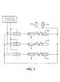
図3を参照すると、複数の位置センサがロボットマニピュレータ56の複数の連結部に関連付けられる。1つの実施形態では、位置センサは、エンコーダ112、114、116である。エンコーダ112、114、116は、回転エンコーダ等の任意の適切なタイプのエンコーダとすることができる。図3に示すように、各エンコーダ112、114、116は、モータM等のアクチュエータに関連付けられる。各エンコーダ112、114、116は、エンコーダが関連付けられたロボットマニピュレータ56の3つのモータ駆動コンポーネントのうちの1つのモータ駆動コンポーネントの角度位置を監視するセンサである。ロボットマニピュレータ56は、2つの追加のエンコーダ、すなわちエンコーダ117及び118を含む。エンコーダ117及び118は、追加の駆動連結部に関連付けられる。幾つかの実施形態において、ロボットマニピュレータ56は、6つの能動関節において6つのエンコーダを有する2アーム構造を含む。 Referring to FIG. 3, a plurality of position sensors are associated with a plurality of connecting portions of the
マニピュレータコントローラ54は、「Surgical Manipulator Capable of Controlling a Tool in either a Semi-Autonomous Mode or a Manual, Boundary Constrained Mode」と題する米国仮特許出願第61/679,258号に記載されているように、ツール22が動かされるべき所望の位置を決定する。この米国仮特許出願の開示は、引用することにより本明細書の一部をなすものとする。この決定、及びツール22の現在の位置(例えば、姿勢)に関する情報に基づいて、マニピュレータコントローラ54は、各連結部が、ツール22を現在の位置から所望の位置に再位置決めするために動かされる必要がある範囲を求める。連結部が位置決めされることになる場所に関するデータは、ロボットマニピュレータ56の能動関節を、連結部を動かすように、それによってツール22を現在のロケーションから所望のロケーションに動かすように制御する関節モータコントローラJMCに転送される。 The
ツール22の現在のロケーションを求めるために、エンコーダ112、114、116、117及び118からのデータを用いて、測定された関節角度が求められる。能動関節の測定された関節角度は、順運動学モジュール(図示せず)に転送される。また、エンコーダ117及び118からの信号も順運動学モジュールに印加される。これらの信号は、これらのエンコーダと一体化した受動関節のための測定された関節角度である。測定された関節角度及びプリロードされたデータに基づいて、順運動学モジュールは、マニピュレータ座標系MNPLにおけるツール22の姿勢を決定する。プリロードされたデータは、連結部及び関節の幾何学を定義するデータである。 To determine the current location of the
1つの実施形態では、マニピュレータコントローラ54及び関節モータコントローラJMCは、指令された位置及び/又は向きにツール22を動かすように動作する位置コントローラを集合的に形成する。位置コントローラは位置制御ループにおいて動作する。位置制御ループは、能動関節ごとに並列又は直列の複数の位置制御ループを含むことができる。位置制御ループは、ツール22の位置を示し、方向付けするように、位置及び向きの情報を処理する。 In one embodiment, the
以下で詳細に示すように、位置センサはプライマリ位置情報を提供する。1つの例において、プライマリ位置情報は、エンコーダ112、114、116、117及び118からの情報と、プリロードされたデータとに基づいて計算されたツール22の姿勢を含む。ステップ204において、エンコーダ112、114、116、117及び118からのデータと、プリロードされたデータとを用いてプライマリ位置情報を計算することができる。さらに又は代替的に、プライマリ位置情報は、マニピュレータ座標系MNPLにおけるツール22の位置及び向きを含む。代替的に、プライマリ位置情報は、マニピュレータ座標系MNPLにおけるツール22の動きを指令する位置コマンドを含む。 As will be described in detail below, the position sensor provides primary position information. In one example, the primary position information includes the attitude of the
ナビゲーションシステムは、セカンダリ位置情報を提供する。より詳細には、ローカライザ34はセカンダリ位置情報を提供する。1つの例では、セカンダリ位置情報は、ステップ200においてローカライザ座標系LCLZにおいて計算されたツール22のナビゲーションベースの姿勢を含む。別の例では、セカンダリ位置情報は、ローカライザ座標系LCLZからマニピュレータ座標系MNPLに変換された位置及び向きのデータを含む。セカンダリ位置情報はナビゲーションコンピュータ26によって処理することができる。 The navigation system provides secondary position information. More specifically, the
図4を参照すると、ローカライザ座標系LCLZ及びマニピュレータ座標系MNPLの相対的な位置は、ナビゲーションコンピュータ26によって変換行列を生成することができるように確立される。変換行列は、アイテムの位置及び向きのデータを、ローカライザ座標系LCLZからマニピュレータ座標系MNPLに変換する。このステップは、外科手技が始まる前に行うことができ、以下で更に説明するように、外科手技中に周期的に行うことができる。さらに、変換行列が最初に生成された後にプライマリ位置情報を生成することができる。 Referring to FIG. 4, the relative positions of the localizer coordinate system LCLZ and the manipulator coordinate system MNPL are established so that a transformation matrix can be generated by the
図5を参照すると、ローカライザ座標系LCLZにおいてツールトラッカ48の位置及び向きが求められ、それによって局所的な座標系LCLZにおいてセカンダリ位置情報を計算することができる。ローカライザ座標系LCLZにおけるツール22のナビゲーションベースの姿勢は、マニピュレータ座標系MNPLの相対姿勢を運動学的に求めることができる姿勢として設定される。 Referring to FIG. 5, the position and orientation of the
ローカライザ座標系LCLZに対するマニピュレータ座標系MNPLの姿勢は、エンコーダ112、114、116、117及び118からのデータと、プリロードされたデータとに基づく。プリロードされたデータは、エンコーダ112、114、116、117及び118、連結部等に対するマニピュレータ座標系MNPLの関係に関連付けられる。結果として、ステップ202において2つの座標系間の変換行列を生成することができる。ツール22は位置コントローラによって動かされ、それによって、ステップ206において、ツール22、そしてツール22の作業端が、次の指令された位置に動かされる。 The attitude of the manipulator coordinate system MNPL relative to the localizer coordinate system LCLZ is based on the data from the
ツール22の新たに取得されたナビゲーションベースの姿勢データを用いて周期的な調整が行われ、変換行列が更新される。変換行列を更新することによって、ローカライザ座標系LCLZに対し、マニピュレータ座標系MNPLがリセットされる。これらの周期的調整の1つの理由は、エンコーダベースのデータが、ロボットマニピュレータ56の連結部の曲げを一切考慮に入れることができないことである。代わりに、そのような曲げは、アームに対する力を推定することによって考慮に入れられる。結果として、ナビゲーションベースのデータは、エンコーダベースのデータを補完する。なぜなら、連結部の曲げに関連付けられた任意の誤差が、例えば、ローカライザ34及びツールトラッカ48を用いて姿勢を測定するときに自動的に考慮に入れられるためである。 Periodic adjustment is performed using newly acquired navigation-based posture data of the
ナビゲーションコンピュータ26は、変換行列を周期的に更新して、マニピュレータ座標系MNPLをリセットする。これは、エンコーダ駆動の姿勢データのみに基づいて、開ループ形式で、ツール22の位置決めの結果生じ得る位置の誤りについて調整するために行われる。これを行うことによって、ツール22のエンコーダベースの位置及び向きが、ナビゲーションコンピュータ26によって提供されるナビゲーションベースの位置及び向きの情報を用いて(すなわち、制御ループを閉じることによって)補正/再較正される。 The
プライマリ位置情報が第1の周波数で求められる。1つの実施形態では、位置センサが第1の周波数においてプライマリ位置情報を求める。さらに又は代替的に、位置コントローラが第1の周波数においてプライマリ位置情報を求めることができる。より詳細には、位置コントローラは、位置センサからの信号を用いて、第1の周波数において位置コマンドを生成することができる。したがって、第1の周波数は、幾つかの例では、位置コマンド周波数として定義することができる。本明細書において説明される例等のそのような例では、「位置コマンド周波数」という用語は、「第1の周波数」の代わりに用いることができる。 Primary position information is determined at the first frequency. In one embodiment, the position sensor determines primary position information at the first frequency. Additionally or alternatively, the position controller can determine primary position information at the first frequency. More specifically, the position controller can generate a position command at the first frequency using a signal from the position sensor. Thus, the first frequency can be defined as the position command frequency in some examples. In such examples, such as those described herein, the term “position command frequency” may be used in place of “first frequency”.
さらに、セカンダリ位置情報が第2の周波数において求められる。詳細には、セカンダリ位置情報は、第2の周波数において変換行列を更新することによって求められる。言い換えると、ローカライザ座標系LCLZからマニピュレータ座標系MNPLへの位置及び向きのデータの変換は、第2の周波数においてに更新される。したがって、第2の周波数は、幾つかの例において、変換更新周波数として定義することができる。本明細書において説明されるもの等のそのような例では、「変換更新周波数」という用語は、「第2の周波数」の代わりに用いることができる。変換更新周波数は、マニピュレータコントローラ54によって確立することができる。さらに又は代替的に、変換更新周波数は、ナビゲーションコンピュータ26及び/又はローカライザ34によって確立することができる。 Further, secondary position information is determined at the second frequency. Specifically, the secondary position information is obtained by updating the transformation matrix at the second frequency. In other words, the conversion of position and orientation data from the localizer coordinate system LCLZ to the manipulator coordinate system MNPL is updated at the second frequency. Thus, the second frequency can be defined as a conversion update frequency in some examples. In such examples, such as those described herein, the term “conversion update frequency” can be used in place of “second frequency”. The conversion update frequency can be established by the
ステップ208において、変換更新周波数に基づいて、変換行列が更新されるか否かの判断が行われる。変換更新周波数による指示によれば変換行列がまだ更新されない場合、本方法はステップ204に続く。変換行列が更新される場合、本方法はステップ200に戻って継続する。 In
位置コントローラは、第1の位置制御モード及び第2の位置制御モードにおいて物体23に対してツール22を位置決めするように構成される。位置コントローラは、プライマリ位置情報及びセカンダリ位置情報に基づいて第1の位置制御モード及び第2の位置制御モードにおいてツール22を位置決めする。 The position controller is configured to position the
図1及び図2に示すように、システムは、周波数コントローラ120を含む。周波数コントローラは、第1の周波数及び第2の周波数のうちの少なくとも1つを調整するように構成される。第1の周波数及び第2の周波数の調整は、第1の位置制御モード及び第2の位置制御モードにおいて行われる。 As shown in FIGS. 1 and 2, the system includes a
1つの実施形態において、周波数コントローラ120は、マニピュレータコントローラ54及びナビゲーションコンピュータ26の双方に結合される。周波数コントローラ120は、任意の適切なロケーションに配置することができる。例えば、図1に示すように、周波数コントローラ120は、ロボットマニピュレータ56内に配置される。代替的に、周波数コントローラ120は、ガイダンスステーション20内に配置することができる。周波数コントローラ120は、スタンドアロンコンポーネントとすることもできるし、マニピュレータコントローラ54又はナビゲーションコンピュータ26等のより大きなデバイスのサブコンポーネントとして一体化することもできる。 In one embodiment,
周波数コントローラ120は、第1の位置制御モードにおける第1の周波数及び第2の周波数が、第2の位置制御モードにおける第1の周波数と第2の周波数との差と異なるように、第1の周波数及び第2の周波数を調整する。1つの実施形態では、第1の周波数と第2の周波数との差は、第1の周波数からの第2の周波数の算術的減算である。例えば、第1の周波数が1KHzであり、第2の周波数が900Hzである場合、差は100Hzである。代替的に、第1の周波数と第2の周波数との差は、第2の周波数からの第1の周波数の算術的減算である。この差は、第1の周波数と第2の周波数との差の絶対値が求められる絶対差とすることができる。当業者であれば、第1の周波数と第2の周波数との差を、限定ではないが、加算、除算、微分、積分等を含む様々な他の算術演算に従って導出することができることを理解する。 The
この差は、任意の所与の位置制御モードにおける動作中の任意の所与の時点に離散的に測定することができる。例えば、第1の位置制御モードにおける第1の周波数と第2の周波数との差は、所与の時点において瞬時に測定される。所与の時点において瞬時に測定された第1の位置制御モードにおける差は、同じ所与の時点において瞬時に測定された第2の位置制御モードにおける差と離散的に異なることができる。代替的に、任意の所与の位置制御モードにおいて、動作中に差を継続的に測定することができる。そのような例では、第1の位置制御モードにおける差は、第2の位置制御モードにおける差と継続的に異なる場合がある。1つの例では、差は或る期間にわたって平均化される。ここで、第1の位置制御モードにおける第1の周波数と第2の周波数との平均的な差は、第2の位置制御モードにおける第1の周波数と第2の周波数との平均的な差と異なる。 This difference can be measured discretely at any given time during operation in any given position control mode. For example, the difference between the first frequency and the second frequency in the first position control mode is measured instantaneously at a given time. The difference in the first position control mode measured instantaneously at a given time can be discretely different from the difference in the second position control mode measured instantaneously at the same given time. Alternatively, the difference can be continuously measured during operation in any given position control mode. In such an example, the difference in the first position control mode may be continuously different from the difference in the second position control mode. In one example, the difference is averaged over a period of time. Here, the average difference between the first frequency and the second frequency in the first position control mode is the average difference between the first frequency and the second frequency in the second position control mode. Different.
第1の周波数と第2の周波数との差は、ツール22の位置速度及びツール22の位置精度又は正確度に影響を及ぼす。位置速度は、ツール22が動く送り速度としても知られる。 The difference between the first frequency and the second frequency affects the position velocity of the
1つの意味において、第1の周波数と第2の周波数との差は、ツール22を動かす際にプライマリ位置情報及びセカンダリ位置情報が用いられる範囲を表す。説明したように、ツール22が比較的大きな対象エリア内に位置決めされているとき、ツール22の位置正確度は、エンコーダベースのプライマリ位置情報から導出されるときよりも、ナビゲーションベースのセカンダリ位置情報から導出されるときに、より高い。 In one sense, the difference between the first frequency and the second frequency represents a range in which primary position information and secondary position information are used when the
高度の位置正確度に対するトレードオフとして、ツール22の位置速度は、プライマリ位置情報から導出されるときと比較して、セカンダリ位置情報から導出されるときに、より低速となる。換言すれば、ツール22の位置速度は、セカンダリ位置情報と比較して、プライマリ位置情報から導出されるときに、より高速となる。 As a trade-off for altitude position accuracy, the position speed of the
一般的に、第1の周波数と第2の周波数との差が増大すると位置速度が増大する。逆に、第1の周波数と第2の周波数との差が減少すると位置速度が減少する。 Generally, the position velocity increases as the difference between the first frequency and the second frequency increases. Conversely, when the difference between the first frequency and the second frequency decreases, the position speed decreases.
さらに、第1の周波数と第2の周波数との差が減少すると、位置精度が増大する。例えば、ツール22が比較的大きな対象エリア内に位置決めされているとき等の幾つかの例では、変換更新周波数が位置コマンド周波数に近づくほど、ツール22の位置決めの正確度が高くなる。他方で、第1の周波数と第2の周波数との差が増大すると、位置正確度が減少する。 Furthermore, when the difference between the first frequency and the second frequency decreases, the position accuracy increases. For example, in some examples, such as when the
1つの実施形態では、第1の位置制御モードにおける第1の周波数と第2の周波数との差は、第2の位置制御モードにおける第1の周波数と第2の周波数との差よりも大きい。幾つかの例では、第1の位置制御モード及び第2の位置制御モードの双方において第1の周波数と第2の周波数との差が非ゼロである。ここで、第1の位置制御モードにおける第1の周波数と第2の周波数との非ゼロの差は、第2の位置制御モードにおける第1の周波数と第2の周波数との非ゼロの差よりも大きい。 In one embodiment, the difference between the first frequency and the second frequency in the first position control mode is greater than the difference between the first frequency and the second frequency in the second position control mode. In some examples, the difference between the first frequency and the second frequency is non-zero in both the first position control mode and the second position control mode. Here, the non-zero difference between the first frequency and the second frequency in the first position control mode is greater than the non-zero difference between the first frequency and the second frequency in the second position control mode. Is also big.
別の実施形態では、第1の位置制御モードにおける第1の周波数と第2の周波数との差は非ゼロである。第1の位置制御モードにおいて、第1周波数は第2の周波数よりも高い。変換行列は、位置コマンドが位置コントローラによって生成される周波数よりも低い変換更新周波数で周期的に更新される。その間、第2の位置制御モードにおける第1の周波数と第2の周波数との差は概ねゼロである。この差は、第1の位置制御モードにおける非ゼロ差よりも低い。第1の周波数は、第2の位置制御モードにおいて実質的に第2の周波数に等しい。言い換えると、変換行列は、位置コマンドが位置コントローラによって生成される周波数と実質的に等しい変換更新周波数において周期的に更新される。 In another embodiment, the difference between the first frequency and the second frequency in the first position control mode is non-zero. In the first position control mode, the first frequency is higher than the second frequency. The transformation matrix is periodically updated at a transformation update frequency that is lower than the frequency at which the position command is generated by the position controller. Meanwhile, the difference between the first frequency and the second frequency in the second position control mode is substantially zero. This difference is lower than the non-zero difference in the first position control mode. The first frequency is substantially equal to the second frequency in the second position control mode. In other words, the transformation matrix is periodically updated at a transformation update frequency that is substantially equal to the frequency at which the position command is generated by the position controller.
したがって、この実施形態では、第1の位置制御モードにおけるツール22の位置速度は、第2の位置制御モードにおけるツール22の位置速度よりも高い。第2の位置制御モードでは、ツール22の位置正確度は、第1の位置制御モードにおけるツール22の位置正確度よりも高い。したがって、第1の位置制御モードは、より大きな対象エリアにおけるバルク切断が所望される場合に、第2の位置制御モードよりも好ましい。一方、第2の位置制御モードは、精密切断が所望される場合に、第1の位置制御モードよりも好ましい。 Therefore, in this embodiment, the position speed of the
この実施形態の場合、第1の位置制御モードにおけるツール22の位置決めは、マニピュレータ座標系MNPLにおけるエンコーダベースの姿勢情報を用いて位置コントローラによって開ループ形式で主に制御される。この第1の位置制御モードでは、比較的高いコマンド周波数、すなわち、複数の連結部及びツール22に関連付けられた応答周波数よりも高い周波数において、位置コマンドが関節モータコントローラJMCに送信される。複数の連結部及びツール22の応答周波数は、位置コマンドに応答してツール22の完全な動き及び整定が生じる周波数である。ロボットマニピュレータ56の連結部、モータ、関節等は、或る程度の可撓性又は遊びを有するので、位置コマンドと、ツール22の完全な動き及び整定との間の応答時間に制限がある。 In the case of this embodiment, the positioning of the
したがって、この実施形態では、第1の位置制御モードにおける変換更新周波数は、位置コマンド周波数未満、かつ連結部及びツール22の応答周波数未満になるように調整される。そうではなく、変換更新周波数が応答周波数よりも高速に設定される場合、システムは不安定になる場合がある。結果として、位置コマンドは、変換更新周波数よりも高い周波数において生成されるので、手術部位においてツール22を位置決めする際の正確度が潜在的により低くなる。 Therefore, in this embodiment, the conversion update frequency in the first position control mode is adjusted to be less than the position command frequency and less than the response frequency of the coupling unit and the
第1の位置制御モードにおける第1の周波数と第2の周波数との差は、様々な度合いとすることができる。幾つかの例では、第1の位置制御モードにおける変換更新周波数は、位置コマンドが関節モータコントローラJMCに送信される周波数の1/10以下である。 The difference between the first frequency and the second frequency in the first position control mode can be various degrees. In some examples, the conversion update frequency in the first position control mode is 1/10 or less of the frequency at which the position command is transmitted to the joint motor controller JMC.
第2の位置制御モードでは、変換更新周波数は、位置コマンドが関節モータコントローラJMCに送信されるのと概ね同じコマンド周波数とすることができる。したがって、ツール22が比較的大きな対象エリアに位置決めされている状況のような幾つかの状況では、システムは、第1の位置制御モードよりも正確に手術部位においてツール22を配置することができる。第2の位置制御モードに切り換えるとき、システムは「低速化」する。換言すれば、ナビゲーションコンピュータ26及び位置制御ループは、ツール22を追跡及び位置決めするように共に機能するが、これは、複数の連結部並びにツール22の動き及び整定に関連付けられた応答周波数未満の周波数で行われる。ここでも、これは不安定性を回避するために行われる。このため、幾つかの実施形態では、変換更新周波数は、連結部の応答周波数に基づいて固定することができ、コマンド周波数は、正確度を調整するために、変換更新周波数に対して調整される。 In the second position control mode, the conversion update frequency can be approximately the same command frequency as the position command is transmitted to the joint motor controller JMC. Thus, in some situations, such as situations where the
第2の位置制御モードにおける第1の周波数と第2の周波数との差は、度合いが変動することができる。幾つかの実施形態では、第2の位置制御モードにおける変換更新周波数は、位置コマンドが関節モータコントローラJMCに送信されるコマンド周波数の1/10よりも高い。 The difference between the first frequency and the second frequency in the second position control mode can vary. In some embodiments, the conversion update frequency in the second position control mode is higher than 1/10 of the command frequency at which the position command is transmitted to the joint motor controller JMC.
さらに、システムは、第1の位置制御モード及び第2の位置制御モードに加えて複数の位置制御モードを含むことができる。例えば、システムは、第1の制御モード及び第2の制御モードと異なる周波数及び/又は位置正確度及び速度パラメータを有する混合モードを含むことができる。 Further, the system can include a plurality of position control modes in addition to the first position control mode and the second position control mode. For example, the system can include a mixed mode having different frequency and / or position accuracy and velocity parameters than the first control mode and the second control mode.
1つの実施形態では、図6に示すように、第1の周波数及び第2の周波数のうちの少なくとも1つを調整することは自律的に行われる。1つの例では、第1の周波数又は第2の周波数は自律的に増大又は減少する。別の例では、第1の周波数と第2の周波数との差は自律的に調整される。 In one embodiment, as shown in FIG. 6, adjusting at least one of the first frequency and the second frequency is done autonomously. In one example, the first frequency or the second frequency increases or decreases autonomously. In another example, the difference between the first frequency and the second frequency is adjusted autonomously.
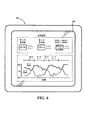
図6に示すように、システムは、周波数コントローラ120と通信するユーザインタフェース130を含むことができる。1つの実施形態では、ユーザインタフェース130はナビゲーションインタフェースであり、第1のディスプレイ28及び/又は第2のディスプレイ29を含む。ユーザインタフェース130は、第1の周波数及び第2の周波数の自律調整に関する情報を医療従事者に通信する。1つの実施形態では、ユーザインタフェース130は、第1の周波数及び第2の周波数のリアルタイムの自律調整を表示する。ユーザインタフェース130は、数値的なリアルタイムの周波数及び周波数間のリアルタイムの差を表示することができる。幾つかの例では、ユーザインタフェース130は、第1の周波数を第2の周波数で除算することによって計算された第1の周波数と第2の周波数との差の大きさを更に表示することができる。例えば、図6に示すように、第1の周波数は第2の周波数の1.25倍高い。さらに、ユーザインタフェース130は、第1の周波数及び第2の周波数のリアルタイムの自律調整を示すチャート等のグラフ情報を表示することができる。ユーザインタフェース130は、医療従事者を支援するための任意の他の適切な情報を提供することができる。例えば、ユーザインタフェース130は、第1の周波数と第2の周波数とのリアルタイムの差を、ツール22の推定の又はリアルタイムの位置正確度及び位置速度と並置することができる。 As shown in FIG. 6, the system can include a
自律調整は、任意の適したイベントに応答して行うことができる。1つの実施形態では、変換更新周波数は、フィードバックに基づいて自律的に変更される。例えば、自律調整は、システムが上記で説明したような自律動作モード又は半自律動作モードに携わっているときに行うことができる。さらに、自律調整は、システムの安定性又は不安定性が判断されるのに応答して行うことができる。更に別の例では、自律調整は、対象ターゲットエリアを決定するのに応答して行われる。第1の周波数及び第2の周波数は、扱われているターゲットエリアの大きさに基づいて自律的に調整することができる。例えば、ターゲットエリアが、ツール22がいずれの方向にも10mmを超えて移動することができないような大きさにされている場合において、ツール22が小さなエリア内で操作されているとき、エンコーダベースのデータを非常に精密することができるので、変換更新周波数を自律的に下げることができる。他方で、ターゲットエリアが、ツール22がいずれの方向にも100mmを超えて移動することができるような大きさにされている場合、変換更新周波数を自律的により高く設定することができる。 Autonomous adjustment can be made in response to any suitable event. In one embodiment, the conversion update frequency is autonomously changed based on feedback. For example, the autonomous adjustment can be performed when the system is engaged in an autonomous operation mode or a semi-autonomous operation mode as described above. Furthermore, the autonomous adjustment can be performed in response to the determination of the stability or instability of the system. In yet another example, the autonomous adjustment is performed in response to determining the target target area. The first frequency and the second frequency can be autonomously adjusted based on the size of the target area being handled. For example, if the target area is sized such that the
さらに、第1の周波数及び第2の周波数の自律調整は、第1の位置制御モードと第2の位置制御モードとの切換えに応答して行うことができる。第1の周波数又は第2の周波数への変更は、例えば、ロボットマニピュレータ56が、より低い位置正確度を要する全体的な切断動作又はバルク切断動作から、より高い位置正確度を要する最終的な切断動作又は微細切断動作に遷移しているときに関連付けることができる。これは、ツール22のバルク切断バーが微細切断バーに交換されるときに行うことができる。バーは、挿入時にマニピュレータコントローラ54によって自動的に認識することができ、このため、位置制御モード間で位置制御モジュールを切り換えることができる。 Furthermore, the autonomous adjustment of the first frequency and the second frequency can be performed in response to switching between the first position control mode and the second position control mode. The change to the first frequency or the second frequency is, for example, that the
同様に、第1の位置制御モード又は第2の位置制御モードの選択は自律的に行うことができる。第1の位置制御モード又は第2の位置制御モードの自律選択は、限定ではないが、第1の周波数及び第2の周波数の自律調整に関係して上記で説明したイベントを含む任意の適切なイベントに応答して行うことができる。他の状況は、様々な理由から位置制御モード間で自動的に切り換えることを必要とする場合がある。さらに、ユーザインタフェース130は、第1の位置制御モード又は第2の位置制御モードの自律選択に関する任意の適切な情報を表示することができる。 Similarly, the selection of the first position control mode or the second position control mode can be performed autonomously. Autonomous selection of the first position control mode or the second position control mode is not limited to any suitable including the events described above in relation to the autonomous adjustment of the first frequency and the second frequency. Can be done in response to an event. Other situations may require automatic switching between position control modes for various reasons. Furthermore, the
図7に示すような別の実施形態では、第1の周波数及び第2の周波数のうちの少なくとも1つを調整することは手動で行われる。ユーザインタフェース130は、医療従事者が、第1の周波数及び第2の周波数のうちの少なくとも1つを選択的に調整することを可能にする。例えば、ユーザインタフェース130は、医療従事者が、任意の所与の位置制御モードについて、第1の周波数又は第2の周波数を選択的に増大又は減少させることを可能にすることができる。また、ユーザインタフェース130は、第1の周波数と第2の周波数との差の選択的な調整を可能にすることができる。ユーザインタフェース130は、任意の所与の位置制御モードについてそのような手動の調整を可能にすることができる。1つの実施形態では、第1の周波数及び第2の周波数の手動の調整は、ユーザ入力パラメータに応答して行うことができる。システムは、ガイダンスステーション20に入力される所望のパラメータに基づいて第1の周波数又は第2の周波数を変更するようにナビゲーションコンピュータ26によって操作されるソフトウェアモジュールである位置制御モジュール109を備えることができる。これらのパラメータは、所望の正確度、精度、手術時間、これらの組合せ等を含むことができる。当然ながら、第1の周波数又は第2の周波数の手動の調整は、限定ではないが、第1の周波数及び第2の周波数の自律調整に関係して上記で説明したイベントを含む任意の他の適切なイベントに応答して行うことができる。 In another embodiment as shown in FIG. 7, adjusting at least one of the first frequency and the second frequency is done manually.
第1の周波数及び第2の周波数及び/又は第1の周波数と第2の周波数との差は、所与の位置制御モードごとに設定し、メモリに記憶することができる。例えば、図7において、サンプルの第1の位置制御モード(バルク)が、1KHzに設定された第1の周波数及び100Hzに設定された第2の周波数を用いて選択される。設定されたパラメータはメモリに記憶することができ、この位置制御モードが後の時点で選択されるときにロードすることができる。 The first frequency and the second frequency and / or the difference between the first frequency and the second frequency can be set for each given position control mode and stored in memory. For example, in FIG. 7, the first position control mode (bulk) of the sample is selected using a first frequency set to 1 KHz and a second frequency set to 100 Hz. The set parameters can be stored in memory and loaded when this position control mode is selected at a later time.
さらに、第1の位置制御モード及び第2の位置制御モードの選択は手動で行うことができる。ユーザインタフェース130は、医療従事者が、第1の位置制御モード及び第2の位置制御モードを、又は複数の他の位置制御モード若しくは混合モード間で、手動で選択することを可能にする。第1の位置制御モード又は第2の位置制御モードの手動の選択は、限定ではないが、第1の位置制御モード及び第2の位置制御モードの自律選択に関して上記で説明したイベントを含む任意の適切なイベントに応答して行うことができる。 Furthermore, the selection of the first position control mode and the second position control mode can be performed manually.
第1の位置制御モード及び第2の位置制御モードの手動の調整、及び/又は第1の位置制御モード及び第2の位置制御モードの手動の選択を通じて、ユーザインタフェース130は、ツール22の位置正確度及び速度にわたるカスタマイズされた制御を可能にする。 Through manual adjustment of the first position control mode and the second position control mode and / or manual selection of the first position control mode and the second position control mode, the
幾つかの実施形態では、第1の周波数及び第2の周波数を調整することは手動で行われるのに対し、第1の位置制御モード及び第2の位置制御モードの選択は自律的に行われる。代替的に、第1の周波数及び第2の周波数を調整することは自律的に行われるのに対し、第1の位置制御モード及び第2の位置制御モードの選択は手動で行われる。 In some embodiments, adjusting the first frequency and the second frequency is done manually, while the selection of the first position control mode and the second position control mode is done autonomously. . Alternatively, the adjustment of the first frequency and the second frequency is performed autonomously, while the selection of the first position control mode and the second position control mode is performed manually.
詳述された明細書から本発明の数多くの特徴及び利点が明らかであり、それゆえ、添付の特許請求の範囲が、本発明の真の趣旨及び範囲に入る本発明の全てのそのような特徴及び利点に及ぶことを意図している。さらに、当業者には数多くの変更及び変形が容易に思い浮かぶことになるので、本発明を図示及び説明されたのと全く同じ構成及び動作に限定することは望ましくなく、それゆえ、本発明の範囲内に入る、全ての適切な変更形態及び均等物が採用される場合がある。
なお、出願当初の特許請求の範囲の記載は以下の通りである。
請求項1:
物体と相互作用するシステムであって、
基部及び複数の連結部を有するロボットマニピュレータと、
前記ロボットマニピュレータに結合され、前記物体と相互作用するように前記基部に対し移動可能であるツールと、
第1の周波数においてプライマリ位置情報を提供する、前記複数の連結部に関連付けられた複数の位置センサと、
第2の周波数においてセカンダリ位置情報を提供するローカライザと、
前記プライマリ位置情報及び前記セカンダリ位置情報に基づいて、第1の位置制御モード及び第2の位置制御モードにおいて物体に対し前記ツールを位置決めするように構成される位置コントローラと、
前記第1の位置制御モードにおける前記第1の周波数と前記第2の周波数との差が、前記第2の位置制御モードにおける前記第1の周波数と前記第2の周波数との差と異なるように、前記第1の位置制御モード及び前記第2の位置制御モードの各々において前記第1の周波数及び前記第2の周波数のうちの少なくとも1つを調整するように構成される周波数コントローラと、
を備える、システム。
請求項2:
前記プライマリ位置情報は、マニピュレータ座標系における前記ツールの動きを指令するためのエンコーダベースの位置コマンドを含む、請求項1に記載のシステム。
請求項3:
前記セカンダリ位置情報は、ローカライザ座標系から前記マニピュレータ座標系に変換された、ナビゲーションベースの位置及び向きのデータを含む、請求項1又は2に記載のシステム。
請求項4:
前記第1の位置制御モードにおける前記第1の周波数と前記第2の周波数との前記差は、前記第2の位置制御モードにおける前記第1の周波数と前記第2の周波数との前記差よりも大きい、請求項1〜3のいずれか1項に記載のシステム。
請求項5:
前記第1の位置制御モードにおける前記第1の周波数と前記第2の周波数との前記差は非ゼロである、請求項1〜4のいずれか1項に記載のシステム。
請求項6:
前記第1の位置制御モードにおいて、前記第1の周波数は前記第2の周波数よりも高い、請求項1〜5のいずれか1項に記載のシステム。
請求項7:
前記第2の位置制御モードにおける前記第1の周波数と前記第2の周波数との前記差はゼロである、請求項1〜4のいずれか1項に記載のシステム。
請求項8:
前記第2の位置制御モードにおいて、前記第1の周波数は前記第2の周波数に実質的に等しい、請求項1〜4及び7のいずれか1項に記載のシステム。
請求項9:
前記第1の位置制御モードにおいて、前記第2の周波数は、前記第1の周波数の約1/10以下であり、前記第2の位置制御モードにおいて、前記第2の周波数は、前記第1の周波数の1/10以上である、請求項1〜6のいずれか1項に記載のシステム。
請求項10:
前記第1の周波数と前記第2の周波数との前記差は、前記ツールの位置速度に影響を与える、請求項1〜9のいずれか1項に記載のシステム。
請求項11:
前記第1の位置制御モードにおける前記ツールの前記位置速度は、前記第2の位置制御モードにおける前記ツールの前記位置速度よりも高い、請求項10に記載のシステム。
請求項12:
前記第1の周波数と前記第2の周波数との前記差は、前記ツールの位置正確度に影響を及ぼす、請求項1〜11のいずれか1項に記載のシステム。
請求項13:
前記第2の位置制御モードにおける前記ツールの前記位置正確度は、前記第1の位置制御モードにおける前記ツールの前記位置正確度よりも高い、請求項12に記載のシステム。
請求項14:
前記第1の周波数及び前記第2の周波数のうちの少なくとも1つの選択的な調整を可能にするために前記周波数コントローラに結合されたインタフェースを更に備える、請求項1〜13のいずれか1項に記載のシステム。
請求項15:
前記第1の位置制御モード及び前記第2の位置制御モードの選択を可能にするために前記周波数コントローラに結合されたインタフェースを更に備える、請求項1〜14のいずれか1項に記載のシステム。
請求項16:
前記複数の位置センサは複数の位置エンコーダを備える、請求項1〜15のいずれか1項に記載のシステム。
請求項17:
ロボットシステムにおいてツールを位置決めする方法であって、
第1の周波数において前記ツールのためのプライマリ位置情報を求めることと、
第2の周波数において前記ツールのためのセカンダリ位置情報を求めることと、
前記プライマリ位置情報及び前記セカンダリ位置情報に基づいて第1の位置制御モード及び第2の位置制御モードにおいて前記ツールを動かすことと、
前記第1の位置制御モードにおける前記第1の周波数と前記第2の周波数との間の差が、前記第2の位置制御モードにおける前記第1の周波数と前記第2の周波数との差と異なるように前記第1の位置制御モード及び前記第2の位置制御モードのそれぞれにおいて前記第1の周波数及び前記第2の周波数のうちの少なくとも1つを調整することと、
を含む、方法。
請求項18:
プライマリ位置情報を求めることは、前記第1の周波数において、マニピュレータ座標系における前記ツールの動きを指令する位置コマンドを生成することを含む、請求項17に記載の方法。
請求項19:
セカンダリ位置情報を求めることは、前記第2の周波数において、ローカライザ座標系からマニピュレータ座標系への、ナビゲーションベースの位置及び向きのデータの変換を更新することを含む、請求項17又は18に記載の方法。
請求項20:
前記第1の位置制御モードにおける前記位置速度が、前記第2の位置制御モードにおける前記位置速度よりも高くなるように、前記第1の周波数と前記第2の周波数との差に基づいて前記ツールの位置速度に影響を与えることを更に含む、請求項17〜19のいずれか1項に記載の方法。
請求項21:
前記第2の位置制御モードにおける前記位置正確度が、前記第1の位置制御モードにおける前記位置正確度よりも高くなるように、前記第1の周波数と前記第2の周波数との差に基づいて前記ツールの位置正確度に影響を与えることを更に含む、請求項17〜20のいずれか1項に記載の方法。
請求項22:
前記第1の周波数及び前記第2の周波数のうちの少なくとも1つを調整することは自律的に行われる、請求項17〜21のいずれか1項に記載の方法。
請求項23:
前記第1の周波数及び前記第2の周波数のうちの少なくとも1つを調整することは手動で行われる、請求項17〜22のいずれか1項に記載の方法。
請求項24:
前記第1の位置制御モード及び前記第2の位置制御モードのうちの少なくとも1つを手動で選択することを更に含む、請求項17〜23のいずれか1項に記載の方法。
請求項25:
前記第1の位置制御モード及び前記第2の位置制御モードを自律的に選択することを更に含む、請求項17〜24のいずれか1項に記載の方法。Numerous features and advantages of the present invention are apparent from the detailed description, and therefore, the appended claims fall within the true spirit and scope of the invention. And intended to cover the benefits. Further, since numerous modifications and changes will readily occur to those skilled in the art, it is not desirable to limit the present invention to the exact construction and operation as illustrated and described. All suitable modifications and equivalents that fall within the scope may be employed.
The description of the claims at the beginning of the application is as follows.
Claim 1:
A system that interacts with objects,
A robot manipulator having a base and a plurality of connecting portions;
A tool coupled to the robot manipulator and movable relative to the base to interact with the object;
A plurality of position sensors associated with the plurality of linkages for providing primary position information at a first frequency;
A localizer providing secondary location information at a second frequency;
A position controller configured to position the tool relative to an object in a first position control mode and a second position control mode based on the primary position information and the secondary position information;
The difference between the first frequency and the second frequency in the first position control mode is different from the difference between the first frequency and the second frequency in the second position control mode. A frequency controller configured to adjust at least one of the first frequency and the second frequency in each of the first position control mode and the second position control mode;
A system comprising:
Claim 2:
The system of
Claim 3:
The system according to
Claim 4:
The difference between the first frequency and the second frequency in the first position control mode is greater than the difference between the first frequency and the second frequency in the second position control mode. The system according to
Claim 5:
The system according to
Claim 6:
The system according to any one of
Claim 7:
The system according to
Claim 8:
The system according to any one of
Claim 9:
In the first position control mode, the second frequency is about 1/10 or less of the first frequency. In the second position control mode, the second frequency is the first frequency. The system according to
Claim 10:
The system according to
Claim 11:
The system according to claim 10, wherein the position speed of the tool in the first position control mode is higher than the position speed of the tool in the second position control mode.
Claim 12:
The system according to
Claim 13:
The system of claim 12, wherein the position accuracy of the tool in the second position control mode is higher than the position accuracy of the tool in the first position control mode.
Claim 14:
The interface of any of claims 1-13, further comprising an interface coupled to the frequency controller to allow selective adjustment of at least one of the first frequency and the second frequency. The described system.
Claim 15:
15. A system according to any one of the preceding claims, further comprising an interface coupled to the frequency controller to allow selection of the first position control mode and the second position control mode.
Claim 16:
The system according to
Claim 17:
A method for positioning a tool in a robot system, comprising:
Determining primary position information for the tool at a first frequency;
Determining secondary position information for the tool at a second frequency;
Moving the tool in a first position control mode and a second position control mode based on the primary position information and the secondary position information;
The difference between the first frequency and the second frequency in the first position control mode is different from the difference between the first frequency and the second frequency in the second position control mode. Adjusting at least one of the first frequency and the second frequency in each of the first position control mode and the second position control mode,
Including a method.
Claim 18:
18. The method of claim 17, wherein determining primary position information includes generating a position command that commands movement of the tool in a manipulator coordinate system at the first frequency.
Claim 19:
19. Finding secondary position information comprises updating a transformation of navigation-based position and orientation data from a localizer coordinate system to a manipulator coordinate system at the second frequency. Method.
Claim 20:
The tool based on the difference between the first frequency and the second frequency so that the position velocity in the first position control mode is higher than the position velocity in the second position control mode. 20. A method according to any one of claims 17 to 19, further comprising influencing the position velocity of.
Claim 21:
Based on the difference between the first frequency and the second frequency so that the position accuracy in the second position control mode is higher than the position accuracy in the first position control mode. 21. A method according to any one of claims 17-20, further comprising influencing the positional accuracy of the tool.
Claim 22:
The method according to any one of claims 17 to 21, wherein adjusting at least one of the first frequency and the second frequency is performed autonomously.
Claim 23:
23. A method according to any one of claims 17 to 22, wherein adjusting at least one of the first frequency and the second frequency is performed manually.
Claim 24:
24. The method of any one of claims 17-23, further comprising manually selecting at least one of the first position control mode and the second position control mode.
Claim 25:
The method according to any one of claims 17 to 24, further comprising autonomously selecting the first position control mode and the second position control mode.
Claims (15)
Translated fromJapanese基部(57)及び複数の連結部を有するロボットマニピュレータ(56)と、
前記ロボットマニピュレータ(56)に結合され、前記物体と相互作用するように前記基部(57)に対し移動可能であるツール(22)と、
第1の周波数においてプライマリ位置情報を提供する、前記複数の連結部に関連付けられた複数の位置センサと、
第2の周波数においてセカンダリ位置情報を提供するローカライザ(34)と、
前記プライマリ位置情報及び前記セカンダリ位置情報に基づいて、第1の位置制御モード及び第2の位置制御モードにおいて物体(23)に対し前記ツール(22)を位置決めするように構成される位置コントローラ(54)と、
前記第1の位置制御モードにおける前記第1の周波数と前記第2の周波数との差が、前記第2の位置制御モードにおける前記第1の周波数と前記第2の周波数との差と異なるように、前記第1の位置制御モード及び前記第2の位置制御モードの各々において前記第1の周波数及び前記第2の周波数のうちの少なくとも1つを調整するように構成される周波数コントローラ(120)と、
を備える、システム。A system that interacts with an object (23),
A robot manipulator (56) having a base (57) and a plurality of coupling parts;
A tool (22) coupled to the robot manipulator (56) and movable relative to the base (57) to interact with the object;
A plurality of position sensors associated with the plurality of linkages for providing primary position information at a first frequency;
A localizer (34) for providing secondary location information at a second frequency;
A position controller (54) configured to position the tool (22) relative to the object (23) in the first position control mode and the second position control mode based on the primary position information and the secondary position information. )When,
The difference between the first frequency and the second frequency in the first position control mode is different from the difference between the first frequency and the second frequency in the second position control mode. A frequency controller (120) configured to adjust at least one of the first frequency and the second frequency in each of the first position control mode and the second position control mode; ,
A system comprising:
前記位置センサが、第1の周波数において前記ツール(22)のためのプライマリ位置情報を求めることと、
前記ローカライザ(34)が、第2の周波数において前記ツール(22)のためのセカンダリ位置情報を求めることと、
前記位置コントローラ(54)が、前記プライマリ位置情報及び前記セカンダリ位置情報に基づいて前記ツールを動かすために第1の位置制御モード及び第2の位置制御モードを提供することと、
前記周波数コントローラ(120)が、前記第1の位置制御モードにおける前記第1の周波数と前記第2の周波数との間の差が、前記第2の位置制御モードにおける前記第1の周波数と前記第2の周波数との差と異なるように前記第1の位置制御モード及び前記第2の位置制御モードのそれぞれにおいて前記第1の周波数及び前記第2の周波数のうちの少なくとも1つを調整することと、
を含む、方法。A method of a robotsystem to position the tool (22), the robot system includes a robot manipulator (56) having a plurality of connecting portions, the tool coupled to said robot manipulator (56) and (22), A plurality of position sensors associated with the plurality of connections, a localizer (34), a position controller (54), and a frequency controller (120), the method comprising:
And said positionsensor to determine the primary location for the tool at the first frequency (22),
Whereinthe localizer (34), and determining a secondary location for the tool (22) at a second frequency,
And that said position controller(54) for providing a first position control mode and the second position control mode in order to move the tool on the basis of the primary position information and the secondary position information,
Wherein the frequency controller (120)is, the difference between the first frequency and said second frequency in said first position control mode is the said first frequency in said second position control mode of the Adjusting at least one of the first frequency and the second frequency in each of the first position control mode and the second position control mode so as to be different from the difference between the first frequency and the second frequency. ,
Including a method.
Therobot system further includesa user interface (130) for manually selecting at least one of the first position control mode and the second position control mode, and / or the first position. 15. The method according to any one of claims 12 to 14, further comprising autonomously selecting a control mode and the second position control mode.
Applications Claiming Priority (3)
| Application Number | Priority Date | Filing Date | Title |
|---|---|---|---|
| US201361886838P | 2013-10-04 | 2013-10-04 | |
| US61/886,838 | 2013-10-04 | ||
| PCT/US2014/059005WO2015051233A1 (en) | 2013-10-04 | 2014-10-03 | System and method for interacting with an object |
Publications (3)
| Publication Number | Publication Date |
|---|---|
| JP2016538893A JP2016538893A (en) | 2016-12-15 |
| JP2016538893A5 JP2016538893A5 (en) | 2017-11-02 |
| JP6393319B2true JP6393319B2 (en) | 2018-09-19 |
Family
ID=51830621
Family Applications (1)
| Application Number | Title | Priority Date | Filing Date |
|---|---|---|---|
| JP2016519742AActiveJP6393319B2 (en) | 2013-10-04 | 2014-10-03 | System and method for interacting with objects |
Country Status (8)
| Country | Link |
|---|---|
| US (1) | US9339346B2 (en) |
| EP (1) | EP3052042B1 (en) |
| JP (1) | JP6393319B2 (en) |
| KR (1) | KR102303657B1 (en) |
| CN (1) | CN105592818B (en) |
| AU (1) | AU2014329381B2 (en) |
| CA (1) | CA2924820A1 (en) |
| WO (1) | WO2015051233A1 (en) |
Families Citing this family (18)
| Publication number | Priority date | Publication date | Assignee | Title |
|---|---|---|---|---|
| KR20250079045A (en) | 2015-05-19 | 2025-06-04 | 마코 서지컬 코포레이션 | System and method for manipulating an anatomy |
| US9687982B1 (en)* | 2015-05-27 | 2017-06-27 | X Development Llc | Adapting programming of a robot and/or control of the robot based on one or more parameters of an end effector of the robot |
| US10583557B2 (en)* | 2017-02-10 | 2020-03-10 | GM Global Technology Operations LLC | Redundant underactuated robot with multi-mode control framework |
| CN107536643A (en)* | 2017-08-18 | 2018-01-05 | 北京航空航天大学 | A kind of augmented reality operation guiding system of Healing in Anterior Cruciate Ligament Reconstruction |
| JP7334499B2 (en)* | 2019-06-27 | 2023-08-29 | ソニーグループ株式会社 | Surgery support system, control device and control method |
| CN112767560A (en)* | 2020-12-30 | 2021-05-07 | 华南理工大学 | Pose adjusting method for three-dimensional simulation model of robot production system |
| US11844583B2 (en) | 2021-03-31 | 2023-12-19 | Moon Surgical Sas | Co-manipulation surgical system having an instrument centering mode for automatic scope movements |
| US12167900B2 (en) | 2021-03-31 | 2024-12-17 | Moon Surgical Sas | Co-manipulation surgical system having automated preset robot arm configurations |
| US11812938B2 (en) | 2021-03-31 | 2023-11-14 | Moon Surgical Sas | Co-manipulation surgical system having a coupling mechanism removeably attachable to surgical instruments |
| US11819302B2 (en) | 2021-03-31 | 2023-11-21 | Moon Surgical Sas | Co-manipulation surgical system having user guided stage control |
| US12042241B2 (en) | 2021-03-31 | 2024-07-23 | Moon Surgical Sas | Co-manipulation surgical system having automated preset robot arm configurations |
| US11832909B2 (en) | 2021-03-31 | 2023-12-05 | Moon Surgical Sas | Co-manipulation surgical system having actuatable setup joints |
| WO2022208414A1 (en) | 2021-03-31 | 2022-10-06 | Moon Surgical Sas | Co-manipulation surgical system for use with surgical instruments for performing laparoscopic surgery |
| US12178418B2 (en) | 2021-03-31 | 2024-12-31 | Moon Surgical Sas | Co-manipulation surgical system having a coupling mechanism removeably attachable to surgical instruments |
| US11839442B1 (en) | 2023-01-09 | 2023-12-12 | Moon Surgical Sas | Co-manipulation surgical system for use with surgical instruments for performing laparoscopic surgery while estimating hold force |
| US11986165B1 (en) | 2023-01-09 | 2024-05-21 | Moon Surgical Sas | Co-manipulation surgical system for use with surgical instruments for performing laparoscopic surgery while estimating hold force |
| US12370001B2 (en) | 2023-01-09 | 2025-07-29 | Moon Surgical Sas | Co-manipulation surgical system having automated user override detection |
| WO2025174937A1 (en)* | 2024-02-13 | 2025-08-21 | Mako Surgical Corp. | System and method for performing robot registration using free-form path |
Family Cites Families (8)
| Publication number | Priority date | Publication date | Assignee | Title |
|---|---|---|---|---|
| US20010034530A1 (en) | 2000-01-27 | 2001-10-25 | Malackowski Donald W. | Surgery system |
| US9867669B2 (en)* | 2008-12-31 | 2018-01-16 | Intuitive Surgical Operations, Inc. | Configuration marker design and detection for instrument tracking |
| US9526587B2 (en)* | 2008-12-31 | 2016-12-27 | Intuitive Surgical Operations, Inc. | Fiducial marker design and detection for locating surgical instrument in images |
| WO2007136769A2 (en)* | 2006-05-19 | 2007-11-29 | Mako Surgical Corp. | Method and apparatus for controlling a haptic device |
| KR20100015541A (en)* | 2007-04-13 | 2010-02-12 | 나이키 인코포레이티드 | Vision cognition and coordination testing and training |
| US8521331B2 (en) | 2009-11-13 | 2013-08-27 | Intuitive Surgical Operations, Inc. | Patient-side surgeon interface for a minimally invasive, teleoperated surgical instrument |
| CN103764061B (en)* | 2011-06-27 | 2017-03-08 | 内布拉斯加大学评议会 | On Tool Tracking System and Computer Assisted Surgery Method |
| WO2013016251A2 (en)* | 2011-07-28 | 2013-01-31 | Alouani Ali T | Image guided surgery trackers using multiple asynchronous sensors |
- 2014
- 2014-10-03CNCN201480054447.5Apatent/CN105592818B/enactiveActive
- 2014-10-03KRKR1020167008754Apatent/KR102303657B1/enactiveActive
- 2014-10-03WOPCT/US2014/059005patent/WO2015051233A1/enactiveApplication Filing
- 2014-10-03JPJP2016519742Apatent/JP6393319B2/enactiveActive
- 2014-10-03EPEP14790423.9Apatent/EP3052042B1/enactiveActive
- 2014-10-03AUAU2014329381Apatent/AU2014329381B2/enactiveActive
- 2014-10-03USUS14/505,801patent/US9339346B2/enactiveActive
- 2014-10-03CACA2924820Apatent/CA2924820A1/ennot_activeAbandoned
Also Published As
| Publication number | Publication date |
|---|---|
| AU2014329381B2 (en) | 2019-05-23 |
| CN105592818B (en) | 2017-11-03 |
| US20150100161A1 (en) | 2015-04-09 |
| WO2015051233A1 (en) | 2015-04-09 |
| KR20160067110A (en) | 2016-06-13 |
| US9339346B2 (en) | 2016-05-17 |
| EP3052042B1 (en) | 2019-11-27 |
| CA2924820A1 (en) | 2015-04-09 |
| AU2014329381A1 (en) | 2016-04-14 |
| CN105592818A (en) | 2016-05-18 |
| KR102303657B1 (en) | 2021-09-23 |
| JP2016538893A (en) | 2016-12-15 |
| EP3052042A1 (en) | 2016-08-10 |
Similar Documents
| Publication | Publication Date | Title |
|---|---|---|
| JP6393319B2 (en) | System and method for interacting with objects | |
| US11529198B2 (en) | Optical and non-optical sensor tracking of objects for a robotic cutting system |
Legal Events
| Date | Code | Title | Description |
|---|---|---|---|
| A521 | Request for written amendment filed | Free format text:JAPANESE INTERMEDIATE CODE: A523 Effective date:20170915 | |
| A621 | Written request for application examination | Free format text:JAPANESE INTERMEDIATE CODE: A621 Effective date:20170915 | |
| A871 | Explanation of circumstances concerning accelerated examination | Free format text:JAPANESE INTERMEDIATE CODE: A871 Effective date:20170915 | |
| A975 | Report on accelerated examination | Free format text:JAPANESE INTERMEDIATE CODE: A971005 Effective date:20170928 | |
| A131 | Notification of reasons for refusal | Free format text:JAPANESE INTERMEDIATE CODE: A131 Effective date:20171024 | |
| A601 | Written request for extension of time | Free format text:JAPANESE INTERMEDIATE CODE: A601 Effective date:20180123 | |
| A521 | Request for written amendment filed | Free format text:JAPANESE INTERMEDIATE CODE: A523 Effective date:20180309 | |
| A131 | Notification of reasons for refusal | Free format text:JAPANESE INTERMEDIATE CODE: A131 Effective date:20180605 | |
| A521 | Request for written amendment filed | Free format text:JAPANESE INTERMEDIATE CODE: A523 Effective date:20180724 | |
| TRDD | Decision of grant or rejection written | ||
| A01 | Written decision to grant a patent or to grant a registration (utility model) | Free format text:JAPANESE INTERMEDIATE CODE: A01 Effective date:20180808 | |
| A61 | First payment of annual fees (during grant procedure) | Free format text:JAPANESE INTERMEDIATE CODE: A61 Effective date:20180824 | |
| R150 | Certificate of patent or registration of utility model | Ref document number:6393319 Country of ref document:JP Free format text:JAPANESE INTERMEDIATE CODE: R150 | |
| R250 | Receipt of annual fees | Free format text:JAPANESE INTERMEDIATE CODE: R250 | |
| R250 | Receipt of annual fees | Free format text:JAPANESE INTERMEDIATE CODE: R250 | |
| R250 | Receipt of annual fees | Free format text:JAPANESE INTERMEDIATE CODE: R250 | |
| R250 | Receipt of annual fees | Free format text:JAPANESE INTERMEDIATE CODE: R250 | |
| R250 | Receipt of annual fees | Free format text:JAPANESE INTERMEDIATE CODE: R250 |