JP6391171B2 - Semiconductor manufacturing system and operation method thereof - Google Patents
Semiconductor manufacturing system and operation method thereofDownload PDFInfo
- Publication number
- JP6391171B2 JP6391171B2JP2015175654AJP2015175654AJP6391171B2JP 6391171 B2JP6391171 B2JP 6391171B2JP 2015175654 AJP2015175654 AJP 2015175654AJP 2015175654 AJP2015175654 AJP 2015175654AJP 6391171 B2JP6391171 B2JP 6391171B2
- Authority
- JP
- Japan
- Prior art keywords
- gas
- exhaust pump
- product
- exhaust
- semiconductor manufacturing
- Prior art date
- Legal status (The legal status is an assumption and is not a legal conclusion. Google has not performed a legal analysis and makes no representation as to the accuracy of the status listed.)
- Active
Links
Images


Classifications
- C—CHEMISTRY; METALLURGY
- C23—COATING METALLIC MATERIAL; COATING MATERIAL WITH METALLIC MATERIAL; CHEMICAL SURFACE TREATMENT; DIFFUSION TREATMENT OF METALLIC MATERIAL; COATING BY VACUUM EVAPORATION, BY SPUTTERING, BY ION IMPLANTATION OR BY CHEMICAL VAPOUR DEPOSITION, IN GENERAL; INHIBITING CORROSION OF METALLIC MATERIAL OR INCRUSTATION IN GENERAL
- C23C—COATING METALLIC MATERIAL; COATING MATERIAL WITH METALLIC MATERIAL; SURFACE TREATMENT OF METALLIC MATERIAL BY DIFFUSION INTO THE SURFACE, BY CHEMICAL CONVERSION OR SUBSTITUTION; COATING BY VACUUM EVAPORATION, BY SPUTTERING, BY ION IMPLANTATION OR BY CHEMICAL VAPOUR DEPOSITION, IN GENERAL
- C23C16/00—Chemical coating by decomposition of gaseous compounds, without leaving reaction products of surface material in the coating, i.e. chemical vapour deposition [CVD] processes
- C23C16/44—Chemical coating by decomposition of gaseous compounds, without leaving reaction products of surface material in the coating, i.e. chemical vapour deposition [CVD] processes characterised by the method of coating
- C23C16/4401—Means for minimising impurities, e.g. dust, moisture or residual gas, in the reaction chamber
- C23C16/4405—Cleaning of reactor or parts inside the reactor by using reactive gases
- C—CHEMISTRY; METALLURGY
- C23—COATING METALLIC MATERIAL; COATING MATERIAL WITH METALLIC MATERIAL; CHEMICAL SURFACE TREATMENT; DIFFUSION TREATMENT OF METALLIC MATERIAL; COATING BY VACUUM EVAPORATION, BY SPUTTERING, BY ION IMPLANTATION OR BY CHEMICAL VAPOUR DEPOSITION, IN GENERAL; INHIBITING CORROSION OF METALLIC MATERIAL OR INCRUSTATION IN GENERAL
- C23C—COATING METALLIC MATERIAL; COATING MATERIAL WITH METALLIC MATERIAL; SURFACE TREATMENT OF METALLIC MATERIAL BY DIFFUSION INTO THE SURFACE, BY CHEMICAL CONVERSION OR SUBSTITUTION; COATING BY VACUUM EVAPORATION, BY SPUTTERING, BY ION IMPLANTATION OR BY CHEMICAL VAPOUR DEPOSITION, IN GENERAL
- C23C16/00—Chemical coating by decomposition of gaseous compounds, without leaving reaction products of surface material in the coating, i.e. chemical vapour deposition [CVD] processes
- C23C16/44—Chemical coating by decomposition of gaseous compounds, without leaving reaction products of surface material in the coating, i.e. chemical vapour deposition [CVD] processes characterised by the method of coating
- C23C16/4401—Means for minimising impurities, e.g. dust, moisture or residual gas, in the reaction chamber
- C23C16/4404—Coatings or surface treatment on the inside of the reaction chamber or on parts thereof
- C—CHEMISTRY; METALLURGY
- C23—COATING METALLIC MATERIAL; COATING MATERIAL WITH METALLIC MATERIAL; CHEMICAL SURFACE TREATMENT; DIFFUSION TREATMENT OF METALLIC MATERIAL; COATING BY VACUUM EVAPORATION, BY SPUTTERING, BY ION IMPLANTATION OR BY CHEMICAL VAPOUR DEPOSITION, IN GENERAL; INHIBITING CORROSION OF METALLIC MATERIAL OR INCRUSTATION IN GENERAL
- C23C—COATING METALLIC MATERIAL; COATING MATERIAL WITH METALLIC MATERIAL; SURFACE TREATMENT OF METALLIC MATERIAL BY DIFFUSION INTO THE SURFACE, BY CHEMICAL CONVERSION OR SUBSTITUTION; COATING BY VACUUM EVAPORATION, BY SPUTTERING, BY ION IMPLANTATION OR BY CHEMICAL VAPOUR DEPOSITION, IN GENERAL
- C23C16/00—Chemical coating by decomposition of gaseous compounds, without leaving reaction products of surface material in the coating, i.e. chemical vapour deposition [CVD] processes
- C23C16/44—Chemical coating by decomposition of gaseous compounds, without leaving reaction products of surface material in the coating, i.e. chemical vapour deposition [CVD] processes characterised by the method of coating
- C23C16/4412—Details relating to the exhausts, e.g. pumps, filters, scrubbers, particle traps
- C—CHEMISTRY; METALLURGY
- C23—COATING METALLIC MATERIAL; COATING MATERIAL WITH METALLIC MATERIAL; CHEMICAL SURFACE TREATMENT; DIFFUSION TREATMENT OF METALLIC MATERIAL; COATING BY VACUUM EVAPORATION, BY SPUTTERING, BY ION IMPLANTATION OR BY CHEMICAL VAPOUR DEPOSITION, IN GENERAL; INHIBITING CORROSION OF METALLIC MATERIAL OR INCRUSTATION IN GENERAL
- C23C—COATING METALLIC MATERIAL; COATING MATERIAL WITH METALLIC MATERIAL; SURFACE TREATMENT OF METALLIC MATERIAL BY DIFFUSION INTO THE SURFACE, BY CHEMICAL CONVERSION OR SUBSTITUTION; COATING BY VACUUM EVAPORATION, BY SPUTTERING, BY ION IMPLANTATION OR BY CHEMICAL VAPOUR DEPOSITION, IN GENERAL
- C23C16/00—Chemical coating by decomposition of gaseous compounds, without leaving reaction products of surface material in the coating, i.e. chemical vapour deposition [CVD] processes
- C23C16/44—Chemical coating by decomposition of gaseous compounds, without leaving reaction products of surface material in the coating, i.e. chemical vapour deposition [CVD] processes characterised by the method of coating
- C23C16/455—Chemical coating by decomposition of gaseous compounds, without leaving reaction products of surface material in the coating, i.e. chemical vapour deposition [CVD] processes characterised by the method of coating characterised by the method used for introducing gases into reaction chamber or for modifying gas flows in reaction chamber
- C23C16/45523—Pulsed gas flow or change of composition over time
- C23C16/45525—Atomic layer deposition [ALD]
- C23C16/45544—Atomic layer deposition [ALD] characterized by the apparatus
- C23C16/45546—Atomic layer deposition [ALD] characterized by the apparatus specially adapted for a substrate stack in the ALD reactor
- H—ELECTRICITY
- H01—ELECTRIC ELEMENTS
- H01L—SEMICONDUCTOR DEVICES NOT COVERED BY CLASS H10
- H01L21/00—Processes or apparatus adapted for the manufacture or treatment of semiconductor or solid state devices or of parts thereof
- H01L21/67—Apparatus specially adapted for handling semiconductor or electric solid state devices during manufacture or treatment thereof; Apparatus specially adapted for handling wafers during manufacture or treatment of semiconductor or electric solid state devices or components ; Apparatus not specifically provided for elsewhere
- H01L21/67005—Apparatus not specifically provided for elsewhere
- H01L21/67011—Apparatus for manufacture or treatment
- H01L21/67017—Apparatus for fluid treatment
- H—ELECTRICITY
- H01—ELECTRIC ELEMENTS
- H01L—SEMICONDUCTOR DEVICES NOT COVERED BY CLASS H10
- H01L21/00—Processes or apparatus adapted for the manufacture or treatment of semiconductor or solid state devices or of parts thereof
- H01L21/67—Apparatus specially adapted for handling semiconductor or electric solid state devices during manufacture or treatment thereof; Apparatus specially adapted for handling wafers during manufacture or treatment of semiconductor or electric solid state devices or components ; Apparatus not specifically provided for elsewhere
- H01L21/67005—Apparatus not specifically provided for elsewhere
- H01L21/67242—Apparatus for monitoring, sorting or marking
- H01L21/67253—Process monitoring, e.g. flow or thickness monitoring
- H—ELECTRICITY
- H01—ELECTRIC ELEMENTS
- H01L—SEMICONDUCTOR DEVICES NOT COVERED BY CLASS H10
- H01L21/00—Processes or apparatus adapted for the manufacture or treatment of semiconductor or solid state devices or of parts thereof
- H01L21/67—Apparatus specially adapted for handling semiconductor or electric solid state devices during manufacture or treatment thereof; Apparatus specially adapted for handling wafers during manufacture or treatment of semiconductor or electric solid state devices or components ; Apparatus not specifically provided for elsewhere
- H01L21/67005—Apparatus not specifically provided for elsewhere
- H01L21/67242—Apparatus for monitoring, sorting or marking
- H01L21/67288—Monitoring of warpage, curvature, damage, defects or the like
- H—ELECTRICITY
- H01—ELECTRIC ELEMENTS
- H01L—SEMICONDUCTOR DEVICES NOT COVERED BY CLASS H10
- H01L22/00—Testing or measuring during manufacture or treatment; Reliability measurements, i.e. testing of parts without further processing to modify the parts as such; Structural arrangements therefor
- H01L22/10—Measuring as part of the manufacturing process
- H01L22/12—Measuring as part of the manufacturing process for structural parameters, e.g. thickness, line width, refractive index, temperature, warp, bond strength, defects, optical inspection, electrical measurement of structural dimensions, metallurgic measurement of diffusions
- H—ELECTRICITY
- H01—ELECTRIC ELEMENTS
- H01L—SEMICONDUCTOR DEVICES NOT COVERED BY CLASS H10
- H01L22/00—Testing or measuring during manufacture or treatment; Reliability measurements, i.e. testing of parts without further processing to modify the parts as such; Structural arrangements therefor
- H01L22/10—Measuring as part of the manufacturing process
- H01L22/14—Measuring as part of the manufacturing process for electrical parameters, e.g. resistance, deep-levels, CV, diffusions by electrical means
Landscapes
- Chemical & Material Sciences (AREA)
- Engineering & Computer Science (AREA)
- Manufacturing & Machinery (AREA)
- Mechanical Engineering (AREA)
- Materials Engineering (AREA)
- Chemical Kinetics & Catalysis (AREA)
- Organic Chemistry (AREA)
- General Chemical & Material Sciences (AREA)
- Metallurgy (AREA)
- Power Engineering (AREA)
- Microelectronics & Electronic Packaging (AREA)
- Computer Hardware Design (AREA)
- Physics & Mathematics (AREA)
- General Physics & Mathematics (AREA)
- Condensed Matter Physics & Semiconductors (AREA)
- Chemical Vapour Deposition (AREA)
- Drying Of Semiconductors (AREA)
Description
Translated fromJapanese本発明の実施形態は、半導体製造システムおよびその運転方法に関する。 Embodiments described herein relate generally to a semiconductor manufacturing system and an operation method thereof.
ALD(Atomic Layer Deposition)装置によりウェハに膜を形成する場合、ALD装置の排気ガスは排気ポンプにより排出される。しかしながら、排気ポンプを停止して再起動する場合、排気ガスにより生成され排気ポンプのケーシングや羽根に付着した副生成物により、排気ポンプを再起動できない可能性がある。理由は、副生成物の膨張やケーシングおよび羽根の収縮により、ケーシングに付着した副生成物と羽根に付着した副生成物とが接触し固着してしまう可能性があるからである。同様の問題は、ウェハを処理するALD装置以外の装置の排気ガスを排気ポンプにより排出する場合にも起こり得る。 When a film is formed on a wafer by an ALD (Atomic Layer Deposition) apparatus, the exhaust gas of the ALD apparatus is exhausted by an exhaust pump. However, when the exhaust pump is stopped and restarted, there is a possibility that the exhaust pump cannot be restarted due to by-products generated by the exhaust gas and attached to the casing and blades of the exhaust pump. The reason is that by-products adhering to the casing and by-products adhering to the blades may come into contact with each other and stick due to expansion of the by-products and contraction of the casing and the blades. A similar problem may occur when exhaust gas from an apparatus other than an ALD apparatus that processes a wafer is exhausted by an exhaust pump.
排気ポンプを適切に再起動することが可能な半導体製造システムおよびその運転方法を提供する。 A semiconductor manufacturing system capable of appropriately restarting an exhaust pump and an operating method thereof are provided.
一の実施形態によれば、半導体製造システムは、ウェハを処理する処理装置と、前記処理装置から排気ガスを排出する排気ポンプと、前記排気ポンプの動作を示す値を測定する測定部とを備える。さらに、前記システムは、前記測定部により測定された前記値に基づいて、前記排気ガスにより生成され前記排気ポンプに付着または混入した生成物の欠片を押し出す第1ガス、前記排気ポンプを冷却する第2ガス、前記排気ポンプに付着した生成物の特性を変化させる第3ガス、または前記排気ポンプに付着した生成物と反応する第4ガスを、前記排気ポンプ内に供給する制御部を備える。 According to one embodiment, a semiconductor manufacturing system includes a processing apparatus that processes a wafer, an exhaust pump that exhausts exhaust gas from the processing apparatus, and a measurement unit that measures a value indicating the operation of the exhaust pump. . Furthermore, the system cools the exhaust pump, a first gas that pushes out a product fragment generated by the exhaust gas and attached to or mixed in the exhaust pump based on the value measured by the measurement unit. And a control unit that supplies the second gas, the third gas that changes the characteristics of the product attached to the exhaust pump, or the fourth gas that reacts with the product attached to the exhaust pump into the exhaust pump.
以下、本発明の実施形態を、図面を参照して説明する。 Hereinafter, embodiments of the present invention will be described with reference to the drawings.
(第1実施形態)
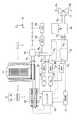
図1は、第1実施形態の半導体製造システムの構成を示す概略図である。(First embodiment)
FIG. 1 is a schematic diagram showing the configuration of the semiconductor manufacturing system according to the first embodiment.
図1の半導体製造システムは、処理装置の例であるALD装置のALD反応炉11と、第1原料ガス供給部12と、第2原料ガス供給部13と、圧力調整バルブ14と、排気ポンプ15と、トラップ部16と、切り換えバルブ17と、測定部21と、制御部の例であるシーケンサ22と、アルゴンガス供給部23と、窒素ガス供給部24と、MFC(Mass Flow Controller)25、26、27とを備えている。 The semiconductor manufacturing system of FIG. 1 includes an
ALD反応炉11は、ALDによりウェハ1の表面に複数の層2a、2bを繰り返し堆積する。これにより、これらの層2a、2bを含む膜2がウェハ1に形成される。ウェハ1の例は、半導体基板や、半導体基板と被加工層とを含む被加工基板である。膜2の例は、酸化膜や窒化膜である。図1は、ALD反応炉11内にウェハ1を搬入し、膜2の形成後にALD反応炉11からウェハ1を搬出する様子を模式的に示している。ALD反応炉11は、複数枚のウェハ1を収容することができる。 The
図1は、ウェハ1の表面に平行で互いに垂直なX方向およびY方向と、ウェハ1の表面に垂直なZ方向を示している。本明細書においては、+Z方向を上方向として取り扱い、−Z方向を下方向として取り扱う。例えば、ウェハ1と膜2との位置関係は、ウェハ1が膜2の下にあると表現される。−Z方向は、重力方向と一致していてもよいし、重力方向と一致していなくてもよい。 FIG. 1 shows an X direction and a Y direction parallel to the surface of the
第1原料ガス供給部12は、ALD反応炉11に第1原料ガスを供給する。第2原料ガス供給部13は、ALD反応炉11に第2原料ガスを供給する。第1原料ガスの例は、ウェハ1の表面に吸着するプリカーサである。第2原料ガスの例は、プリカーサと反応して膜2を形成する酸化剤である。なお、本実施形態の半導体製造システムは、原料ガス供給部を1台のみ備えていてもよいし、原料ガス供給部を3台以上備えていてもよい。 The first source
圧力調整バルブ14は、ALD反応炉11に配管P1により接続されており、ALD反応炉11からの排気ガスの流通や流量を制御するために使用される。本実施形態の半導体製造システムは、圧力調整バルブ14の開度を調整することにより、ALD反応炉11内の圧力を制御することができる。The
排気ポンプ15は、圧力調整バルブ14に配管P2により接続されており、ALD反応炉11から排気ガスを排出するように動作する。排気ポンプ15は、配管P2に接続された排気ガスの入口A1と、配管P3に接続された排気ガスの出口A2とを備えている。The
トラップ部16は、排気ポンプ15に配管P3により接続されており、ALD反応炉11からの排気ガスから所定の物質を除去する。所定の物質の例は、排気ガスにより生成された副生成物である。The
切り換えバルブ17は、トラップ部16に配管P4により接続されており、ALD反応炉11からの排気ガスを流す流路を切り換える。符号B1は、排気ガスを排気用の流路に流す様子を示している。符号B2は、排気ガスを除害用の流路に流す様子を示している。Switching
測定部21は、排気ポンプ15の動作を示す値を測定する。測定部21は例えば、排気ポンプ15の回転、電流、音、振動、または温度を示す値を測定する。このような値の例は、排気ポンプ15の回転数、排気ポンプ15内の電流値、排気ポンプ15付近の音のデシベル値、排気ポンプ15の振動の振動数、排気ポンプ15内の温度などである。 The
シーケンサ22は、半導体製造システムの種々の動作を制御する。例えば、シーケンサ22は、測定部21により測定された値に基づいて、アルゴンガス供給部23、窒素ガス供給部24、MFC25、26、27の動作を制御する。シーケンサ22による制御の詳細については、後述する。 The
アルゴンガス供給部23は、アルゴン(Ar)ガスをMFC25を介して供給口R1に供給する。供給口R1は、配管P2に設けられている。アルゴンガスは、アルゴンガス供給部23から供給口R1を介して排気ポンプ15内に供給される。MFC25は、供給口R1に供給されるアルゴンガスの質量流量を調整するために使用される。アルゴンガスは、排気ポンプ15を冷却するために使用される。アルゴンガスは、第2ガスの例である。The argon
窒素ガス供給部24は、窒素(N2)ガスをMFC26、27を介して供給口R2、R3に供給する。供給口R2は、配管P2に設けられている。供給口R3は、排気ポンプ15の入口A1と出口A2との間に設けられている。窒素ガスは、窒素ガス供給部24から供給口R2、R3の一方または両方を介して排気ポンプ15内に供給される。MFC26は、供給口R2に供給される窒素ガスの質量流量を調整するために使用される。MFC27は、供給口R3に供給される窒素ガスの質量流量を調整するために使用される。窒素ガスは、排気ポンプ15内で副生成物の欠片などが排気ポンプ15の駆動部(例えばロータ)に噛み込まないように、副生成物の欠片を押し出すために使用される。窒素ガスは、第1ガスの例である。The nitrogen
なお、アルゴンガス供給部23と窒素ガス供給部24は、1台以上のガス供給部の例である。また、MFC25、26、27は、1台以上の流量調整部の例である。本実施形態の半導体製造システムは、MFC26用の窒素ガス供給部と、MCF27用の窒素ガス供給部とを別々に備えていてもよい。 The argon
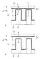
図2は、第1実施形態の排気ポンプ15の問題を説明するための断面図である。 FIG. 2 is a cross-sectional view for explaining the problem of the
図2(a)に示すように、排気ポンプ15は、ケーシング15aと、ケーシング15a内に設けられたロータ15bと、ロータ15bに取り付けられた羽根15cを備えている。ロータ15bは、ケーシング15a内で羽根15cと共に回転する。排気ポンプ15は、羽根15cの回転により、ALD反応炉11から排気ガスを排出することができる。ケーシング15aは、第1部分の例である。ロータ15bと羽根15cは、第2部分の例である。 As shown in FIG. 2A, the
図2(a)は、動作中の排気ポンプ15を示している。図2(a)では、ロータ15bが回転している。符号S1は、ケーシング15aの内面を示す。符号S2は、ケーシング15aの内面S1に対向する羽根15cの外面を示す。符号D1は、ケーシング15aの内面S1と羽根15cの外面S2との間の距離を示す。FIG. 2A shows the
図2(a)は、排気ポンプ15に付着した副生成物31を示している。副生成物31は、ALD反応炉11からの排気ガスにより生成され、ケーシング15aの内面S1や羽根15cの外面S2などに付着する。副生成物31は、排気ポンプ15の上流で排気ガスにより生成され、排気ポンプ15に混入する場合もある。副生成物31の例は、膜2と同じ物質である。副生成物31は、本開示の生成物の例である。FIG. 2A shows the by-
図2(b)は、急停止する排気ポンプ15を示している。図2(b)では、ロータ15bの回転が急停止される。この場合、排気ポンプ15の温度が急激に低下することで、ケーシング15a、ロータ15b、および羽根15cが収縮する。そのため、内面S1と外面S2が矢印C1、C2のように互いに近づき、内面S1と外面S2との距離が短くなる。図2(b)は、この距離がD1からD2に変化した様子を示している。また、この状態で排気ポンプ15内に大気が混入すると、副生成物31が膨張する。膨張の理由は、副生成物31が大気中の水分を吸収することや、副生成物31が大気中の水分により加水分解されることなどである。FIG. 2B shows the
副生成物31が膨張し排気ポンプ15が収縮すると、内面S1の副生成物31と外面S2の副生成物31とが接触し固着してしまう。よって、排気ポンプ15を再起動する際に、ロータ15bが回転しないまたは回転しにくくなる。その結果、排気ポンプ15を再起動することができなくなる。When the by-
図3は、第1実施形態の排気ポンプ15の問題を説明するための断面図である。 FIG. 3 is a cross-sectional view for explaining the problem of the
図3(a)は、動作中の排気ポンプ15を示している。図3(b)は、ゆっくり停止する排気ポンプ15を示している。この場合、副生成物31や排気ポンプ15の温度がゆっくり低下することで、内面S1の副生成物31や外面S2の副生成物31の一部が、ロータ15bの回転が完全に停止するまでに削られる。よって、内面S1の副生成物31と外面S2の副生成物31とが固着することを防止でき、排気ポンプ15を再起動することができる。FIG. 3A shows the
排気ポンプ15は例えば、半導体製造システムのメンテナンス時に停止される。この場合、図2(b)のように排気ポンプ15を急停止すると、排気ポンプ15を再起動することができなくなる。この問題は、図3(b)のように排気ポンプ15をゆっくり停止することで対処可能である。しかしながら、図3(b)の場合には、排気ポンプ15を停止するために長い時間が掛かってしまう。また、図3(b)の場合でも副生成物31が固着する可能性は残り、その場合には排気ポンプ15を再起動できなくなる。 For example, the
図4は、第1実施形態の排気ポンプ15の運転方法を説明するための断面図である。 FIG. 4 is a cross-sectional view for explaining an operation method of the
図4(a)は、動作中の排気ポンプ15を示している。図4(a)では、窒素ガス供給部24から排気ポンプ15内に窒素ガスを供給する。図4(a)は、排気ポンプ15に付着または混入した副生成物31の欠片32の落下物を示している。本実施形態では、流量の大きい窒素ガスを排気ポンプ15内に供給することで、排気ポンプ15内で欠片32などが排気ポンプ15の駆動部(例えばロータ15b)に噛み込まないように、欠片32を押し出すことができる。さらに、欠片32は、流量の大きい窒素ガスに押し出され、内面S1と外面S2の副生成物31を削り落とす。本実施形態では、窒素ガスが排気ポンプ15を冷却することを抑制するために、窒素ガス供給部24で加熱された窒素ガスを排気ポンプ15内に供給してもよい。FIG. 4A shows the
本実施形態によれば、排気ポンプ15内に窒素ガスを供給することで、内面S1の副生成物31と外面S2の副生成物31とが固着することを抑制することができる。これにより、排気ポンプ15を再起動できない事態を防止することが可能となる。According to this embodiment, by supplying nitrogen gas to the
図4(b)も、動作中の排気ポンプ15を示している。図4(b)では、アルゴンガス供給部25から排気ポンプ15内にアルゴンガスを供給する。アルゴンガスは、熱伝導率が低いという性質を有している。よって、本実施形態では、アルゴンガスを排気ポンプ15内に供給することで、おおむねケーシング15aのみを冷却することができる。理由は、回転中のロータ15bは熱を発しているため、熱伝導率の低いアルゴンガスではあまり冷却されないからである。その結果、ケーシング15aのみが矢印C1のように収縮し、内面S1の副生成物31と外面S2の副生成物31が接触する。この際、ロータ15bは回転しているため、この接触により内面S1の副生成物31と外面S2の副生成物31が互いに削られる。FIG. 4B also shows the
本実施形態によれば、排気ポンプ15内にアルゴンガスを供給することで、内面S1と外面S2の副生成物31の接触を誘発することができ、内面S1と外面S2から副生成物31を削り落とすことができる。これにより、排気ポンプ15を再起動できない事態を防止することが可能となる。According to this embodiment, by supplying the argon
なお、本実施形態の排気ポンプ15は、羽根15cの外面S2にコーティング膜15dを有することが望ましい。これにより、内面S1と外面S2の副生成物31の接触により羽根15cが損傷することを防止することができる。コーティング膜15dの例は、めっき層やポリマー膜である。The
本実施形態では、動作中の排気ポンプ15に窒素ガスやアルゴンガスを供給した後、排気ポンプ15を停止する。よって、本実施形態によれば、排気ポンプ15をゆっくり停止しなくても、排気ポンプ15を適切に再起動することが可能となる。本実施形態では、窒素ガスとアルゴンガスは、排気ポンプ15内に同時に供給してもよいし、排気ポンプ15内に別々に供給してもよい。以下、図5を参照して、窒素ガスとアルゴンガスの供給タイミングや供給量について説明する。 In the present embodiment, after supplying nitrogen gas or argon gas to the
図5は、第1実施形態の排気ポンプ15の運転方法を説明するためのグラフである。 FIG. 5 is a graph for explaining an operation method of the
図5の縦軸は、排気ポンプ15内の所定の地点で測定部21により測定された電流値を示す。図5の横軸は、時間を示す。符号I0は、電流値の閾値を示す。The vertical axis in FIG. 5 indicates the current value measured by the
排気ポンプ15内の副生成物31の付着量が少ない場合、電流値は閾値I0よりも十分に低くなる。しかしながら、副生成物31の付着量が多くなると、矢印E1のように電流値が増加する。理由は、副生成物31によりロータ15bが回転しにくくなり、排気ポンプ15がロータ15bの回転数を維持するために電流値を増加させるからである。副生成物31の付着量がさらに多くなると、矢印E2のように電流値がさらに増加し、電流値が閾値I0よりも高くなる。この場合、動作中の排気ポンプ15が、副生成物31により停止してしまう可能性もある。If the attached amount of by-
本実施形態のシーケンサ22は、測定部21から電流値の測定結果を受信し、この電流値に基づいて窒素ガスとアルゴンガスを排気ポンプ15内に供給する。具体的には、シーケンサ22は、電流値が閾値I0より低い場合には、窒素ガス供給部24とアルゴンガス供給部23に供給停止信号を出力し、窒素ガスとアルゴンガスの供給を停止する。また、シーケンサ22は、電流値が閾値I0より高い場合には、窒素ガス供給部24とアルゴンガス供給部23に供給指示信号を出力し、窒素ガスとアルゴンガスを排気ポンプ15内に供給する。これにより、副生成物31の付着量を低減することができ、ロータ15bを再び回転しやすくすることができる。窒素ガスとアルゴンガスは例えば、電流値が閾値I0よりも低くなるまで供給される。The
また、本実施形態のシーケンサ22は、測定部21からの電流値に基づいて、窒素ガスの流量とアルゴンガスの流量を制御する。例えば、シーケンサ22は、電流値と閾値I0との差が増加した場合には、MFC26または27により窒素ガスの流量を増加させ、MFC25によりアルゴンガスの流量を増加させる。また、シーケンサ22は、電流値と閾値I0との差が減少した場合には、MFC26または27により窒素ガスの流量を減少させ、MFC25によりアルゴンガスの流量を減少させる。これにより、副生成物31の付着量をより効果的に低減することができる。Further, the
なお、窒素ガスとアルゴンガスの供給は、異なる閾値により制御してもよい。また、窒素ガスとアルゴンガスの供給は、異なる種類の測定値により制御してもよい。例えば、シーケンサ22は、排気ポンプ15内の電流値に基づいて窒素ガスを供給し、排気ポンプ15付近の音のデシベル値に基づいてアルゴンガスを供給してもよい。 Note that the supply of nitrogen gas and argon gas may be controlled by different threshold values. The supply of nitrogen gas and argon gas may be controlled by different types of measurement values. For example, the
以上のように、本実施形態の測定部21は、排気ポンプ15の動作を示す値を測定し、本実施形態のシーケンサ22は、測定部21により測定された値に基づいて、欠片32を押し出して副生成物31を削り落とす第1ガスまたは排気ポンプ15を冷却する第2ガスを排気ポンプ15内に供給する。第1ガスの例は窒素ガスであり、第2ガスの例はアルゴンガスである。よって、本実施形態によれば、排気ポンプ15の動作中に副生成物31を適切に処理し、排気ポンプ15を適切に再起動することが可能となる。 As described above, the
なお、本実施形態では、副生成物31を削り落とすために、動作中の排気ポンプ15内に、副生成物31の欠片32を模擬する模擬材料を供給してもよい。このような模擬材料の例は、副生成物31と同じ材質のパウダーである。本実施形態によれば、このような模擬材料を使用し、流量の大きい窒素ガスで押し出すことで、副生成物31を削り落とすことが可能となる。 In this embodiment, in order to scrape off the by-
排気ポンプ15の動作中に、窒素ガスの流量を複数段階に変化させる実験を行った。この実験では、動作中の排気ポンプ15が欠片32により停止してしまう頻度を測定した。その結果、窒素ガスの流量が増加するほど、排気ポンプ15が停止する頻度が減少することが分かった。 During the operation of the
(第2実施形態)
図6は、第2実施形態の半導体製造システムの構成を示す概略図である。(Second Embodiment)
FIG. 6 is a schematic diagram showing the configuration of the semiconductor manufacturing system of the second embodiment.
図6の半導体製造システムは、図1に示す構成要素に加えて、水分供給部28とMFC29とを備えている。水分供給部28は、1台以上のガス供給部の例である。MFC29は、1台以上の流量調整部の例である。 The semiconductor manufacturing system of FIG. 6 includes a
水分供給部28は、水分を含むガスをMFC29を介して供給口R4に供給する。供給口R4は、配管P2に設けられている。このようなガスの例は、空気である。空気は、水分供給部28から供給口R4を介して排気ポンプ15内に供給される。MFC29は、供給口R4に供給される空気の質量流量を調整するために使用される。空気は、排気ガスにより生成され排気ポンプ15に付着した副生成物31の特性を変化させるために使用される。空気は、第3ガスの例である。
なお、水分供給部28は、フッ酸(HF)ガスを供給するフッ酸供給部に置き換えてもよい。フッ酸ガスは、副生成物31と反応させるために使用可能である。フッ酸ガスは、第4ガスの例である。 The
図7は、第2実施形態の排気ポンプ15の運転方法を説明するための断面図である。 FIG. 7 is a cross-sectional view for explaining an operation method of the
図7は、動作中の排気ポンプ15を示している。図7では、水分供給部28から排気ポンプ15内に空気を供給する。本実施形態では、空気を排気ポンプ15内に供給することで、内面S1や外面S2の副生成物31を水分にさらす。その結果、副生成物31が水分を吸収することや、副生成物31が水分により加水分解されることにより、副生成物31の特性が変化する。具体的には、副生成物31の膜質が劣化して、副生成物31がもろく削れやすくなる。FIG. 7 shows the
よって、本実施形態によれば、排気ポンプ15内に空気を供給することで、副生成物31を内面S1や外面S2から削り落とすことが容易となる。これにより、排気ポンプ15を再起動できない事態を防止することが可能となる。Therefore, according to this embodiment, by supplying air to the
一方、内面S1や外面S2の副生成物31をフッ酸ガスにさらすことでも、副生成物31の膜質が劣化して、副生成物31が内面S1や外面S2から除去しすくなる。理由は、フッ酸ガスは、エッチングで頻繁に使用されることからも明らかなように、多くの副生成物31と反応しやすいからである。なお、本実施形態では、フッ酸ガス以外のエッチングガスを使用してもよい。On the other hand, by exposing the by-
空気やフッ酸ガスの供給タイミングや供給量は、窒素ガスとアルゴンガスの供給タイミングや供給量と同様に制御可能である。本実施形態のシーケンサ22は、測定部21から電流値の測定結果を受信し、この電流値に基づいて空気(またはフッ酸ガス)を排気ポンプ15内に供給する。シーケンサ22は、空気の供給と停止を水分供給部28により制御し、空気の流量をMFC29により制御する。 The supply timing and supply amount of air and hydrofluoric acid gas can be controlled similarly to the supply timing and supply amount of nitrogen gas and argon gas. The
なお、窒素ガス、アルゴンガス、および空気の供給は、異なる閾値により制御してもよい。また、窒素ガス、アルゴンガス、および空気の供給は、異なる種類の測定値により制御してもよい。例えば、シーケンサ22は、排気ポンプ15内の電流値に基づいて窒素ガスを供給し、排気ポンプ15付近の音のデシベル値に基づいてアルゴンガスを供給し、排気ポンプ15内の温度に基づいて空気を供給してもよい。 Note that the supply of nitrogen gas, argon gas, and air may be controlled by different threshold values. Further, the supply of nitrogen gas, argon gas, and air may be controlled by different types of measurement values. For example, the
以上のように、本実施形態のシーケンサ22は、測定部21により測定された値に基づいて、副生成物31の欠片32を押し出す第1ガス、排気ポンプ15を冷却する第2ガス、副生成物31の特性を変化させる第3ガス、または副生成物31と反応する第4ガスを排気ポンプ15内に供給する。第1ガスの例は窒素ガスであり、第2ガスの例はアルゴンガスであり、第3ガスの例は空気であり、第4ガスの例はフッ酸ガスである。よって、本実施形態によれば、排気ポンプ15の動作中に副生成物31を適切に処理し、排気ポンプ15を適切に再起動することが可能となる。 As described above, the
なお、第1および第2実施形態のALD反応炉11は、ウェハ1を処理するその他の装置に置き換えてもよい。このような装置の例は、ウェハ1を加熱する炉や、ウェハ1上の膜2を加工するチャンバなどである。第1および第2実施形態の排気ポンプ15は、このような装置の排気ガスにも適用可能である。 Note that the
以上、いくつかの実施形態を説明したが、これらの実施形態は、例としてのみ提示したものであり、発明の範囲を限定することを意図したものではない。本明細書で説明した新規なシステムおよび方法は、その他の様々な形態で実施することができる。また、本明細書で説明したシステムおよび方法の形態に対し、発明の要旨を逸脱しない範囲内で、種々の省略、置換、変更を行うことができる。添付の特許請求の範囲およびこれに均等な範囲は、発明の範囲や要旨に含まれるこのような形態や変形例を含むように意図されている。 Although several embodiments have been described above, these embodiments are presented as examples only and are not intended to limit the scope of the invention. The novel systems and methods described herein can be implemented in a variety of other forms. Various omissions, substitutions, and changes can be made to the system and method embodiments described in the present specification without departing from the scope of the invention. The appended claims and their equivalents are intended to include such forms and modifications as fall within the scope and spirit of the invention.
1:ウェハ、2:膜、2a、2b:層、
11:ALD反応炉、12:第1原料ガス供給部、13:第2原料ガス供給部、
14:圧力調整バルブ、15:排気ポンプ、
15a:ケーシング、15b:ロータ、15c:羽根、15d:コーティング膜、
16:トラップ部、17:切り換えバルブ、21:測定部、22:シーケンサ、
23:アルゴンガス供給部、24:窒素ガス供給部、
25、26、27:MFC、28:水分供給部、29:MFC、
31:副生成物、32:欠片1: wafer, 2: film, 2a, 2b: layer,
11: ALD reactor, 12: first source gas supply unit, 13: second source gas supply unit,
14: Pressure adjusting valve, 15: Exhaust pump,
15a: casing, 15b: rotor, 15c: blade, 15d: coating film,
16: Trap part, 17: Switching valve, 21: Measuring part, 22: Sequencer,
23: Argon gas supply unit, 24: Nitrogen gas supply unit,
25, 26, 27: MFC, 28: moisture supply unit, 29: MFC,
31: By-product, 32: Fragment
Claims (9)
Translated fromJapanese前記処理装置から排気ガスを排出する排気ポンプと、
前記排気ポンプの動作を示す値を測定する測定部と、
前記測定部により測定された前記値に基づいて、前記排気ガスにより生成され前記排気ポンプに付着または混入した生成物の欠片を押し出す第1ガス、前記排気ポンプを冷却する第2ガス、前記排気ポンプに付着した前記生成物の特性を変化させる第3ガス、または前記排気ポンプに付着した前記生成物と反応する第4ガスを、前記排気ポンプ内に供給する制御部と、
を備え、
前記排気ポンプは、第1部分と、前記第1部分内で回転し、前記第1部分の内面に対向する外面を有する第2部分とを備え、
前記第2ガスは、前記第1部分の前記内面に付着した前記生成物と、前記第2部分の前記外面に付着した前記生成物とが接触するように、前記排気ポンプを冷却する、
半導体製造システム。A processing apparatus for processing the wafer;
An exhaust pump for exhausting exhaust gas from the processing device;
A measuring unit for measuring a value indicating the operation of the exhaust pump;
Based on the value measured by the measurement unit, a first gas that pushes out a piece of a product that is generated by the exhaust gas and adheres to or enters the exhaust pump, a second gas that cools the exhaust pump, and the exhaust pump A control unit that supplies a third gas that changes the characteristics of the product attached to the exhaust gas or a fourth gas that reacts with the product attached to the exhaust pump into the exhaust pump;
Equipped witha,
The exhaust pump includes a first portion and a second portion that rotates within the first portion and has an outer surface facing an inner surface of the first portion;
The second gas cools the exhaust pump so that the product adhering to the inner surface of the first part and the product adhering to the outer surface of the second part are in contact with each other;
Semiconductor manufacturing system.
前記第1、第2、第3、または第4ガスを供給する1台以上のガス供給部と、
前記第1、第2、第3、または第4ガスの流量を調整する1台以上の流量調整部と、
を備える請求項1から7のいずれか1項に記載の半導体製造システム。further,
One or more gas supply units for supplying the first, second, third or fourth gas;
One or more flow rate adjusters for adjusting the flow rate of the first, second, third, or fourth gas;
The semiconductor manufacturing system of any one of Claim 1 to7 provided with these.
前記処理装置から排気ガスを排気ポンプにより排出し、
前記排気ポンプの動作を示す値を測定部により測定し、
前記測定部により測定された前記値に基づいて、前記排気ガスにより生成され前記排気ポンプに付着または混入した生成物の欠片を押し出す第1ガス、前記排気ポンプを冷却する第2ガス、前記排気ポンプに付着した前記生成物の特性を変化させる第3ガス、または前記排気ポンプに付着した前記生成物と反応する第4ガスを、前記排気ポンプ内に供給する、
ことを含み、
前記排気ポンプは、第1部分と、前記第1部分内で回転し、前記第1部分の内面に対向する外面を有する第2部分とを備え、
前記第2ガスは、前記第1部分の前記内面に付着した前記生成物と、前記第2部分の前記外面に付着した前記生成物とが接触するように、前記排気ポンプを冷却する、
半導体製造システムの運転方法。The wafer is processed by the processing equipment,
Exhaust gas is exhausted from the processing device by an exhaust pump;
A value indicating the operation of the exhaust pump is measured by the measurement unit,
Based on the value measured by the measurement unit, a first gas that pushes out a piece of a product that is generated by the exhaust gas and adheres to or enters the exhaust pump, a second gas that cools the exhaust pump, and the exhaust pump Supplying a third gas that changes the characteristics of the product attached to the gas or a fourth gas that reacts with the product attached to the exhaust pump into the exhaust pump;
Look at includingit,
The exhaust pump includes a first portion and a second portion that rotates within the first portion and has an outer surface facing an inner surface of the first portion;
The second gas cools the exhaust pump so that the product adhering to the inner surface of the first part and the product adhering to the outer surface of the second part are in contact with each other;
A method for operating a semiconductor manufacturing system.
Priority Applications (2)
| Application Number | Priority Date | Filing Date | Title |
|---|---|---|---|
| JP2015175654AJP6391171B2 (en) | 2015-09-07 | 2015-09-07 | Semiconductor manufacturing system and operation method thereof |
| US15/016,730US20170067153A1 (en) | 2015-09-07 | 2016-02-05 | Semiconductor manufacturing system and method of operating the same |
Applications Claiming Priority (1)
| Application Number | Priority Date | Filing Date | Title |
|---|---|---|---|
| JP2015175654AJP6391171B2 (en) | 2015-09-07 | 2015-09-07 | Semiconductor manufacturing system and operation method thereof |
Publications (2)
| Publication Number | Publication Date |
|---|---|
| JP2017054850A JP2017054850A (en) | 2017-03-16 |
| JP6391171B2true JP6391171B2 (en) | 2018-09-19 |
Family
ID=58190161
Family Applications (1)
| Application Number | Title | Priority Date | Filing Date |
|---|---|---|---|
| JP2015175654AActiveJP6391171B2 (en) | 2015-09-07 | 2015-09-07 | Semiconductor manufacturing system and operation method thereof |
Country Status (2)
| Country | Link |
|---|---|
| US (1) | US20170067153A1 (en) |
| JP (1) | JP6391171B2 (en) |
Families Citing this family (3)
| Publication number | Priority date | Publication date | Assignee | Title |
|---|---|---|---|---|
| US11155916B2 (en)* | 2018-09-21 | 2021-10-26 | Taiwan Semiconductor Manufacturing Co., Ltd. | Apparatus and methods for pumping gases from a chamber |
| WO2020261518A1 (en)* | 2019-06-27 | 2020-12-30 | カンケンテクノ株式会社 | Exhaust gas detoxification unit |
| KR102422257B1 (en)* | 2022-01-25 | 2022-07-18 | 주식회사 윤성이엔지 | Gas pipe for semiconductor manufacturing facility |
Family Cites Families (65)
| Publication number | Priority date | Publication date | Assignee | Title |
|---|---|---|---|---|
| JP2515831B2 (en)* | 1987-12-18 | 1996-07-10 | 株式会社日立製作所 | Screen vacuum pump |
| US5443368A (en)* | 1993-07-16 | 1995-08-22 | Helix Technology Corporation | Turbomolecular pump with valves and integrated electronic controls |
| KR950007378B1 (en)* | 1990-04-06 | 1995-07-10 | 가부시끼 가이샤 히다찌 세이사꾸쇼 | Vacuum pump |
| JPH05133385A (en)* | 1991-11-11 | 1993-05-28 | Hitachi Ltd | Dry vacuum pump |
| DE19508566A1 (en)* | 1995-03-10 | 1996-09-12 | Balzers Pfeiffer Gmbh | Molecular vacuum pump with cooling gas device and method for its operation |
| JPH09202973A (en)* | 1996-01-24 | 1997-08-05 | Tokyo Electron Ltd | Discharge system structure of film formation treating device |
| JPH09228052A (en)* | 1996-02-19 | 1997-09-02 | Toshiba Corp | Exhaust device for vacuum film forming / etching equipment |
| JP3400293B2 (en)* | 1996-05-01 | 2003-04-28 | 株式会社東芝 | CVD apparatus and cleaning method thereof |
| JP3550465B2 (en)* | 1996-08-30 | 2004-08-04 | 株式会社日立製作所 | Turbo vacuum pump and operating method thereof |
| US5827370A (en)* | 1997-01-13 | 1998-10-27 | Mks Instruments, Inc. | Method and apparatus for reducing build-up of material on inner surface of tube downstream from a reaction furnace |
| KR100253089B1 (en)* | 1997-10-29 | 2000-05-01 | 윤종용 | Chemical vapor deposition apparatus |
| US6099649A (en)* | 1997-12-23 | 2000-08-08 | Applied Materials, Inc. | Chemical vapor deposition hot-trap for unreacted precursor conversion and effluent removal |
| US6371744B1 (en)* | 1998-03-23 | 2002-04-16 | Taiko Kikai Industries Co., Ltd. | Dry screw vacuum pump having spheroidal graphite cast iron rotors |
| FR2783883B1 (en)* | 1998-09-10 | 2000-11-10 | Cit Alcatel | METHOD AND DEVICE FOR AVOIDING DEPOSITS IN A TURBOMOLECULAR PUMP WITH MAGNETIC OR GAS BEARING |
| US6374831B1 (en)* | 1999-02-04 | 2002-04-23 | Applied Materials, Inc. | Accelerated plasma clean |
| US6197119B1 (en)* | 1999-02-18 | 2001-03-06 | Mks Instruments, Inc. | Method and apparatus for controlling polymerized teos build-up in vacuum pump lines |
| US6468490B1 (en)* | 2000-06-29 | 2002-10-22 | Applied Materials, Inc. | Abatement of fluorine gas from effluent |
| JP4387573B2 (en)* | 1999-10-26 | 2009-12-16 | 東京エレクトロン株式会社 | Process exhaust gas monitoring apparatus and method, semiconductor manufacturing apparatus, and semiconductor manufacturing apparatus management system and method |
| US6773687B1 (en)* | 1999-11-24 | 2004-08-10 | Tokyo Electron Limited | Exhaust apparatus for process apparatus and method of removing impurity gas |
| JP2002155891A (en)* | 2000-11-22 | 2002-05-31 | Seiko Instruments Inc | Vacuum pump |
| US6938638B2 (en)* | 2000-12-28 | 2005-09-06 | Kabushiki Kaisha Toshiba | Gas circulating-processing apparatus |
| JP4138267B2 (en)* | 2001-03-23 | 2008-08-27 | 株式会社東芝 | Semiconductor manufacturing apparatus, vacuum pump life prediction method, and vacuum pump repair timing determination method |
| JP2003077782A (en)* | 2001-08-31 | 2003-03-14 | Toshiba Corp | Method for manufacturing semiconductor device |
| JP4592235B2 (en)* | 2001-08-31 | 2010-12-01 | 株式会社東芝 | Fault diagnosis method for production equipment and fault diagnosis system for production equipment |
| JP2003074468A (en)* | 2001-08-31 | 2003-03-12 | Toshiba Corp | Vacuum evacuation system and monitoring / control method thereof |
| JP2003077907A (en)* | 2001-08-31 | 2003-03-14 | Toshiba Corp | Abnormal stop avoidance method and abnormal stop avoidance system for production equipment |
| US6896764B2 (en)* | 2001-11-28 | 2005-05-24 | Tokyo Electron Limited | Vacuum processing apparatus and control method thereof |
| JP4156830B2 (en)* | 2001-12-13 | 2008-09-24 | エドワーズ株式会社 | Vacuum pump |
| JP4099092B2 (en)* | 2002-03-26 | 2008-06-11 | 東京エレクトロン株式会社 | Substrate processing apparatus, substrate processing method, and high-speed rotary valve |
| US6739840B2 (en)* | 2002-05-22 | 2004-05-25 | Applied Materials Inc | Speed control of variable speed pump |
| JP3692106B2 (en)* | 2002-09-27 | 2005-09-07 | 株式会社東芝 | Manufacturing apparatus and life prediction method of rotating machine |
| US6868760B1 (en)* | 2003-02-12 | 2005-03-22 | Pratt-Read Corporation | Tool locking mechanism |
| KR101151954B1 (en)* | 2002-10-14 | 2012-06-01 | 에드워즈 리미티드 | Rotary piston vacuum pump with washing installation |
| JP4235429B2 (en)* | 2002-10-17 | 2009-03-11 | キヤノン株式会社 | Method for measuring gas in sealed container, and method for manufacturing sealed container and image display device |
| KR100680863B1 (en)* | 2003-02-04 | 2007-02-09 | 동경 엘렉트론 주식회사 | Treatment system and operation method of this treatment system |
| JP3872027B2 (en)* | 2003-03-07 | 2007-01-24 | 株式会社東芝 | Cleaning method and semiconductor manufacturing apparatus |
| JP4320323B2 (en)* | 2003-11-20 | 2009-08-26 | 株式会社日立国際電気 | Semiconductor device manufacturing method and substrate processing apparatus |
| US7278831B2 (en)* | 2003-12-31 | 2007-10-09 | The Boc Group, Inc. | Apparatus and method for control, pumping and abatement for vacuum process chambers |
| US7021903B2 (en)* | 2003-12-31 | 2006-04-04 | The Boc Group, Inc. | Fore-line preconditioning for vacuum pumps |
| JP2005320905A (en)* | 2004-05-10 | 2005-11-17 | Boc Edwards Kk | Vacuum pump |
| GB0416385D0 (en)* | 2004-07-22 | 2004-08-25 | Boc Group Plc | Gas abatement |
| EP1898455B1 (en)* | 2005-06-20 | 2013-05-15 | Tohoku University | Process for producing an interlayer insulating film |
| US8466049B2 (en)* | 2005-07-29 | 2013-06-18 | Hitachi Kokusai Electric Inc. | Semiconductor device producing method with selective epitaxial growth |
| KR100706792B1 (en)* | 2005-08-01 | 2007-04-12 | 삼성전자주식회사 | A semiconductor device manufacturing apparatus having a pump unit and a method for cleaning the pump unit |
| US8026113B2 (en)* | 2006-03-24 | 2011-09-27 | Tokyo Electron Limited | Method of monitoring a semiconductor processing system using a wireless sensor network |
| US7519885B2 (en)* | 2006-03-31 | 2009-04-14 | Tokyo Electron Limited | Monitoring a monolayer deposition (MLD) system using a built-in self test (BIST) table |
| JP5045894B2 (en)* | 2006-05-09 | 2012-10-10 | 株式会社島津製作所 | Magnetic bearing device |
| KR101213689B1 (en)* | 2006-06-12 | 2012-12-18 | 주식회사 테라텍 | Apparatus for cleaning exhaust portion and vacuum pump of the semiconductor and LCD process reaction chamber |
| US20080047578A1 (en)* | 2006-08-24 | 2008-02-28 | Taiwan Semiconductor Manufacturing Co., Ltd. | Method for preventing clogging of reaction chamber exhaust lines |
| US8636019B2 (en)* | 2007-04-25 | 2014-01-28 | Edwards Vacuum, Inc. | In-situ removal of semiconductor process residues from dry pump surfaces |
| JP4430718B2 (en)* | 2008-03-21 | 2010-03-10 | 三井造船株式会社 | Atomic layer deposition system |
| EP2314877B1 (en)* | 2008-07-14 | 2018-08-22 | Edwards Japan Limited | Vacuum pump |
| JP5036849B2 (en)* | 2009-08-27 | 2012-09-26 | 株式会社日立国際電気 | Semiconductor device manufacturing method, cleaning method, and substrate processing apparatus |
| US8747762B2 (en)* | 2009-12-03 | 2014-06-10 | Applied Materials, Inc. | Methods and apparatus for treating exhaust gas in a processing system |
| JP5562058B2 (en)* | 2010-02-04 | 2014-07-30 | 株式会社荏原製作所 | Turbo molecular pump |
| KR101597008B1 (en)* | 2010-08-05 | 2016-02-23 | 가부시키가이샤 에바라 세이사꾸쇼 | Exhaust system |
| JP2012049342A (en)* | 2010-08-27 | 2012-03-08 | Hitachi Kokusai Electric Inc | Apparatus and method of processing substrate |
| CN103443901B (en)* | 2011-03-28 | 2017-09-15 | 应用材料公司 | Method and apparatus for selectively depositing epitaxial germanium alloy stressors |
| US8778066B2 (en)* | 2011-09-23 | 2014-07-15 | Shenzhen China Star Optoelectronics Technology Co., Ltd. | Vacuum pump exhaust pipe of chemical vapor deposition apparatus and relevant vacuum pump |
| KR101427726B1 (en)* | 2011-12-27 | 2014-08-07 | 가부시키가이샤 히다치 고쿠사이 덴키 | Substrate processing apparatus and method of manufacturing semiconductor device |
| CN104246983B (en)* | 2012-04-24 | 2017-03-29 | 应用材料公司 | Gas Recovery and Abatement Systems for High Volume Epitaxial Silicon Deposition Systems |
| KR20140136594A (en)* | 2013-05-20 | 2014-12-01 | 삼성전자주식회사 | Exhausting apparatus and film deposition facilities including the same |
| WO2015182699A1 (en)* | 2014-05-30 | 2015-12-03 | 株式会社 荏原製作所 | Gas-evacuation system |
| US9695512B2 (en)* | 2014-09-02 | 2017-07-04 | Kabushiki Kaisha Toshiba | Semiconductor manufacturing system and semiconductor manufacturing method |
| JP2017183603A (en)* | 2016-03-31 | 2017-10-05 | 東芝メモリ株式会社 | Epitaxial growth system |
- 2015
- 2015-09-07JPJP2015175654Apatent/JP6391171B2/enactiveActive
- 2016
- 2016-02-05USUS15/016,730patent/US20170067153A1/ennot_activeAbandoned
Also Published As
| Publication number | Publication date |
|---|---|
| JP2017054850A (en) | 2017-03-16 |
| US20170067153A1 (en) | 2017-03-09 |
Similar Documents
| Publication | Publication Date | Title |
|---|---|---|
| JP6391171B2 (en) | Semiconductor manufacturing system and operation method thereof | |
| JP2021120346A (en) | Heat treatment of heat treated ceramic substrates with ceramic coatings and coated ceramics | |
| TWI750669B (en) | Plasma processing device and atmosphere opening method | |
| JP5166138B2 (en) | Semiconductor device manufacturing method and semiconductor device manufacturing apparatus | |
| IL272839B1 (en) | A quartz crystal microbalance sensor for monitoring a manufacturing process and a related method | |
| US20070012099A1 (en) | Vacuum line and a method of monitoring such a line | |
| TW200405401A (en) | Thermal processing apparatus and method for evacuating a process chamber | |
| US20050284575A1 (en) | Processing system and operating method of processing system | |
| US12359306B2 (en) | Deposition processing systems having active temperature control and associated methods | |
| JP6270067B2 (en) | Method and apparatus for adjusting operating parameters of vacuum pump device | |
| JP6911705B2 (en) | How to operate the film forming apparatus and the film forming apparatus | |
| WO2018043446A1 (en) | Method for cleaning semiconductor production chamber | |
| KR20230034353A (en) | Removable CVD polymer film for surface protection and extended queue period | |
| TWI751970B (en) | Systems and methods for reducing copper contamination due to substrate processing chambers with components made of alloys including copper | |
| CN109643671B (en) | Self-repairing semiconductor wafer processing | |
| JP2013135044A (en) | Semiconductor manufacturing equipment | |
| WO2022265070A1 (en) | Exhaust pipe, exhaust apparatus, and product attachement preventing method | |
| US20230207305A1 (en) | Residue-free removal of stimulus responsive polymers from substrates | |
| TWI722578B (en) | Apparatus and method for pumping gases from a chamber | |
| JP2005019593A (en) | Heat treatment method and apparatus | |
| JP6980125B2 (en) | Manufacturing method of substrate processing equipment and semiconductor equipment | |
| TW201724253A (en) | Selective removal of boron doped carbon hard mask layers | |
| JP5304934B2 (en) | Method for operating vacuum pump and method for manufacturing semiconductor device | |
| JP2011231345A (en) | Sputtering apparatus and method for maintaining the same | |
| JP3111663B2 (en) | Plasma equipment |
Legal Events
| Date | Code | Title | Description |
|---|---|---|---|
| A711 | Notification of change in applicant | Free format text:JAPANESE INTERMEDIATE CODE: A712 Effective date:20170530 | |
| A621 | Written request for application examination | Free format text:JAPANESE INTERMEDIATE CODE: A621 Effective date:20170802 | |
| A977 | Report on retrieval | Free format text:JAPANESE INTERMEDIATE CODE: A971007 Effective date:20180518 | |
| A131 | Notification of reasons for refusal | Free format text:JAPANESE INTERMEDIATE CODE: A131 Effective date:20180525 | |
| A521 | Request for written amendment filed | Free format text:JAPANESE INTERMEDIATE CODE: A523 Effective date:20180717 | |
| TRDD | Decision of grant or rejection written | ||
| A01 | Written decision to grant a patent or to grant a registration (utility model) | Free format text:JAPANESE INTERMEDIATE CODE: A01 Effective date:20180727 | |
| A61 | First payment of annual fees (during grant procedure) | Free format text:JAPANESE INTERMEDIATE CODE: A61 Effective date:20180820 | |
| R150 | Certificate of patent or registration of utility model | Ref document number:6391171 Country of ref document:JP Free format text:JAPANESE INTERMEDIATE CODE: R150 | |
| S111 | Request for change of ownership or part of ownership | Free format text:JAPANESE INTERMEDIATE CODE: R313111 | |
| R350 | Written notification of registration of transfer | Free format text:JAPANESE INTERMEDIATE CODE: R350 |