JP6385369B2 - Transportable safety inspection system - Google Patents
Transportable safety inspection systemDownload PDFInfo
- Publication number
- JP6385369B2 JP6385369B2JP2015556177AJP2015556177AJP6385369B2JP 6385369 B2JP6385369 B2JP 6385369B2JP 2015556177 AJP2015556177 AJP 2015556177AJP 2015556177 AJP2015556177 AJP 2015556177AJP 6385369 B2JP6385369 B2JP 6385369B2
- Authority
- JP
- Japan
- Prior art keywords
- container
- inspection system
- legs
- inspection
- trailer
- Prior art date
- Legal status (The legal status is an assumption and is not a legal conclusion. Google has not performed a legal analysis and makes no representation as to the accuracy of the status listed.)
- Active
Links
Images


Classifications
- G—PHYSICS
- G01—MEASURING; TESTING
- G01V—GEOPHYSICS; GRAVITATIONAL MEASUREMENTS; DETECTING MASSES OR OBJECTS; TAGS
- G01V5/00—Prospecting or detecting by the use of ionising radiation, e.g. of natural or induced radioactivity
- G01V5/20—Detecting prohibited goods, e.g. weapons, explosives, hazardous substances, contraband or smuggled objects
- G01V5/22—Active interrogation, i.e. by irradiating objects or goods using external radiation sources, e.g. using gamma rays or cosmic rays
- G01V5/222—Active interrogation, i.e. by irradiating objects or goods using external radiation sources, e.g. using gamma rays or cosmic rays measuring scattered radiation
- G—PHYSICS
- G01—MEASURING; TESTING
- G01V—GEOPHYSICS; GRAVITATIONAL MEASUREMENTS; DETECTING MASSES OR OBJECTS; TAGS
- G01V5/00—Prospecting or detecting by the use of ionising radiation, e.g. of natural or induced radioactivity
- G01V5/20—Detecting prohibited goods, e.g. weapons, explosives, hazardous substances, contraband or smuggled objects
- G01V5/22—Active interrogation, i.e. by irradiating objects or goods using external radiation sources, e.g. using gamma rays or cosmic rays
- G—PHYSICS
- G01—MEASURING; TESTING
- G01N—INVESTIGATING OR ANALYSING MATERIALS BY DETERMINING THEIR CHEMICAL OR PHYSICAL PROPERTIES
- G01N23/00—Investigating or analysing materials by the use of wave or particle radiation, e.g. X-rays or neutrons, not covered by groups G01N3/00 – G01N17/00, G01N21/00 or G01N22/00
- G01N23/02—Investigating or analysing materials by the use of wave or particle radiation, e.g. X-rays or neutrons, not covered by groups G01N3/00 – G01N17/00, G01N21/00 or G01N22/00 by transmitting the radiation through the material
- G01N23/06—Investigating or analysing materials by the use of wave or particle radiation, e.g. X-rays or neutrons, not covered by groups G01N3/00 – G01N17/00, G01N21/00 or G01N22/00 by transmitting the radiation through the material and measuring the absorption
- G01N23/083—Investigating or analysing materials by the use of wave or particle radiation, e.g. X-rays or neutrons, not covered by groups G01N3/00 – G01N17/00, G01N21/00 or G01N22/00 by transmitting the radiation through the material and measuring the absorption the radiation being X-rays
- G—PHYSICS
- G01—MEASURING; TESTING
- G01V—GEOPHYSICS; GRAVITATIONAL MEASUREMENTS; DETECTING MASSES OR OBJECTS; TAGS
- G01V5/00—Prospecting or detecting by the use of ionising radiation, e.g. of natural or induced radioactivity
- G01V5/20—Detecting prohibited goods, e.g. weapons, explosives, hazardous substances, contraband or smuggled objects
- G01V5/22—Active interrogation, i.e. by irradiating objects or goods using external radiation sources, e.g. using gamma rays or cosmic rays
- G01V5/232—Active interrogation, i.e. by irradiating objects or goods using external radiation sources, e.g. using gamma rays or cosmic rays having relative motion between the source, detector and object other than by conveyor
- G—PHYSICS
- G01—MEASURING; TESTING
- G01V—GEOPHYSICS; GRAVITATIONAL MEASUREMENTS; DETECTING MASSES OR OBJECTS; TAGS
- G01V5/00—Prospecting or detecting by the use of ionising radiation, e.g. of natural or induced radioactivity
- G01V5/20—Detecting prohibited goods, e.g. weapons, explosives, hazardous substances, contraband or smuggled objects
- G01V5/22—Active interrogation, i.e. by irradiating objects or goods using external radiation sources, e.g. using gamma rays or cosmic rays
- G01V5/224—Multiple energy techniques using one type of radiation, e.g. X-rays of different energies
Landscapes
- Physics & Mathematics (AREA)
- General Physics & Mathematics (AREA)
- Life Sciences & Earth Sciences (AREA)
- High Energy & Nuclear Physics (AREA)
- Geophysics (AREA)
- General Life Sciences & Earth Sciences (AREA)
- Health & Medical Sciences (AREA)
- Chemical & Material Sciences (AREA)
- General Health & Medical Sciences (AREA)
- Biochemistry (AREA)
- Pathology (AREA)
- Immunology (AREA)
- Analytical Chemistry (AREA)
- Toxicology (AREA)
- Analysing Materials By The Use Of Radiation (AREA)
- Crystallography & Structural Chemistry (AREA)
- Nuclear Medicine, Radiotherapy & Molecular Imaging (AREA)
- Radiology & Medical Imaging (AREA)
Description
Translated fromJapanese本出願は、2013年1月31日に出願された米国仮出願番号61/759,211号で発明の名称が「運搬可能な安全性検査システム」に基づくものである。 This application is based on US Provisional Application No. 61 / 759,211 filed on January 31, 2013, and the title of the invention is “Transportable Safety Inspection System”.
本明細書は、運搬可能な検査システムに関する。特に本明細書は、様々な高さで通過する車両や貨物の総合的な安全チェックを実行するために複数の調査地点に設置される運搬可能な統合X線検査システムに関する。 The present description relates to a transportable inspection system. In particular, the present specification relates to a transportable integrated X-ray inspection system installed at a plurality of survey points to perform comprehensive safety checks of vehicles and cargo passing at various heights.
不正取引や密輸やテロにより、非侵入型の検査システムの必要性が増している。この検査システムの範囲は、駐車中の車両に対する縁石側からの検査から混雑した交通量の多いポートにまで及ぶ。交通システムは、国境を越えて商品を効率的に移動させるものであるが、同時に武器や爆発物や不正薬物、貴金属などの禁制品を含める機会も提供するからである。ポートという字句は、一般的には港湾を意味するが、国境検問所や通関手続き地をも意味する。 Fraudulent transactions, smuggling and terrorism have increased the need for non-intrusive inspection systems. The scope of this inspection system ranges from inspection from the curb side to parked vehicles to congested high traffic ports. This is because the transportation system moves goods efficiently across borders, but also provides the opportunity to include prohibited items such as weapons, explosives, illicit drugs, and precious metals. The term port generally refers to a port, but also refers to a border checkpoint and customs clearance.
X線システムは医療、産業、保安検査の目的で用いられる。なぜならこのシステムは人の眼では見えない内部空間の像をコスト効率よく生成できるからである。X線又はその種の放射線に曝された物体は、異なる量のX線照射を吸収し、それ故X線ビームを多かれ少なかれ減衰し、物体の特性である放射の伝達又は後方散乱レベルになる。減衰する放射又は後方散乱の放射は、照射された対象の容量を有益に描写するために用いられる。安全検査装置に用いられる単一エネルギX線配置の代表的な装置は、ファン形状又はスキャンX線ビームを備え、これは検査対象を通過するか後方散乱される。吸収されるか後方散乱されたX線は、ビームが対象を通過した後に複数の検知器で測定され、画像全体が生成されて操作者に提供される。 X-ray systems are used for medical, industrial, and security purposes. This is because this system can cost-effectively generate an image of the internal space that cannot be seen by the human eye. An object exposed to x-rays or such radiation absorbs different amounts of x-ray radiation and thus more or less attenuates the x-ray beam, leading to radiation transmission or backscatter levels characteristic of the object. Attenuating radiation or backscattered radiation is used to beneficially depict the volume of the illuminated object. Typical devices with a single energy X-ray arrangement used in safety inspection devices comprise a fan-shaped or scanned X-ray beam that passes through the object being examined or is backscattered. Absorbed or backscattered x-rays are measured by a plurality of detectors after the beam has passed through the object, and the entire image is generated and provided to the operator.
場所が限られている一方で必要性が高まっているなか,付加的な検査設備を通常の方法で設置することは困難になってきている。更に、ポートの操作者に長期間の検査装置の設置を約束するには、選定された場所は必ずしも永久的ではない。更に、高エネルギX線ソース又は線形加速器(LINAC)を備えるシステムは、物質を遮蔽するための(一般的にはコンクリートまたはビルの形態)主要投資が必要であるか又は、ビルの周囲に立入禁止区域(デッドスペース)を備える必要がある。いずれの場合も、検査すべき貨物コンテナの寸法に依存したビルの専有面積についての要求が過度に著しくなる。 As the need is increasing while the space is limited, it is becoming difficult to install additional inspection equipment in the usual way. Furthermore, the selected location is not necessarily permanent in order to promise the port operator to install the inspection device for a long time. In addition, systems with high energy x-ray sources or linear accelerators (LINAC) require major investments to shield materials (typically in the form of concrete or buildings) or are off limits around buildings It is necessary to provide an area (dead space). In either case, the requirement for the occupied area of the building that depends on the dimensions of the cargo container to be inspected becomes excessively significant.
適応性のある高度な検査能力の必要性のためには、可動の検査システムにより適切な問題解決を提供できる。このようなシステムは再配置可能であり、装置を収容するための永久的なビルへの投資は避けられるので、用地を割り当てることが重要な問題ではなくなり、このようなシステムを導入することで,取り壊し作業を減らせる。また、可動検査システムは操作者に対して、より高い処理能力によって、貨物、積荷、車両、その他のコンテナのより多くの列を検査する能力を提供する。 For the need for adaptive advanced inspection capabilities, mobile inspection systems can provide adequate problem solving. Such systems are relocatable and investment in permanent buildings to accommodate the equipment is avoided, so allocating land is no longer an important issue. By introducing such systems, Demolition work can be reduced. The mobile inspection system also provides the operator with the ability to inspect more rows of cargo, loads, vehicles, and other containers with higher throughput.
従来の検査システムは、剛性が低いこと、作業が困難であること、及び又は視界が小さいことなどの不利益があった。特に、従来の再配置可能な検査システムは、少なくとも2本のブームを有し、一方のブームには複数の検知器が収納され、他方のブームには少なくとも1個のX線ソースが収納される。複数の検知機とX線ソースは同期的に動作して、移動する車両上の貨物をスキャンする。従来の単一ブームの再配置可能な検査システムでは、X線ソースはトラックまたは平台上に位置し、複数の検出器はトラックから外方に延びるブーム構造に位置する。これらのシステムは、スキャンエンジンシステムを移動させることに特徴づけられ、そこでは、ソース・検出器システムは検査されるべき静止した対象に対して移動する。更に、複数の検出器と放射ソースは、可動ベッド、ブーム又は車両のいずれかに載置されて、車両と一体的に結合される。そのために、最適の携帯性のためまた、調整可能な配置をして、異なる寸法の貨物や積荷、車両、その他のコンテナのより広い列を収容することを目的として、全体のシステムを分解することの柔軟性が制約される。その結果、これらのシステムは配置が複雑化し、いくつかの不都合や制約を突きつけるものである。 Conventional inspection systems have disadvantages such as low rigidity, difficulty in work, and / or low visibility. In particular, conventional relocatable inspection systems have at least two booms, one boom containing a plurality of detectors and the other boom containing at least one x-ray source. . Multiple detectors and x-ray sources operate synchronously to scan cargo on moving vehicles. In conventional single-boom repositionable inspection systems, the x-ray source is located on a track or a flat platform and the multiple detectors are located on a boom structure that extends outward from the track. These systems are characterized by moving the scan engine system, where the source and detector system moves relative to a stationary object to be examined. Further, the plurality of detectors and the radiation source are mounted on either the movable bed, the boom, or the vehicle and are integrally coupled to the vehicle. Therefore, for optimal portability, the entire system can also be disassembled with the aim of accommodating a wider row of cargos, loads, vehicles and other containers of different dimensions in an adjustable arrangement. Flexibility is limited. As a result, these systems are complex to deploy and present some inconveniences and limitations.
そのために、トラック又は車両に牽引されたトレーラに、短時間で積み込み可能で、瞬時かつ容易に調査場所に設置できる検査方法やシステムの改良が望まれる。 Therefore, it is desired to improve an inspection method and system that can be loaded in a short time on a trailer that is pulled by a truck or a vehicle and that can be installed at an investigation place instantly and easily.
また、調査場所に輸送するために特殊な高価な輸送車両を必要としない運搬可能な検査システムが望まれる。 In addition, a transportable inspection system that does not require a special expensive transportation vehicle for transportation to an investigation site is desired.
更に、軽量で、検査のために瞬時に設置できる運搬可能な検査システムが望まれる。 Furthermore, a transportable inspection system that is lightweight and can be installed instantaneously for inspection is desired.
本明細書は、容易にかつ瞬時に設置可能な非侵襲型の保安検査システムを提供する。 The present specification provides a non-invasive security inspection system that can be easily and instantaneously installed.
また本明細書は、例えば限定的ではないが、調査が必要とされる複数の場所に輸送される補強された箱体のようなコンテナに容易に入れるように設計された放射線検査アレンジメントを提供する。 The specification also provides a radiological examination arrangement designed to be easily placed in a container, such as, but not limited to, a reinforced box that is transported to multiple locations where investigation is required. .
また本明細書は、トラックまたは輸送車両で牽引されたトレーラに載置されるコンテナであって調査が必要とされる複数の場所に輸送されるコンテナに、容易に入れるように設計された放射線検査アレンジメントを提供する。 This document also describes a radiological examination designed to be easily placed in a container mounted on a trailer pulled by a truck or transport vehicle and transported to multiple locations where investigation is required. Provide arrangements.
また本明細書は、調査地点への輸送に際して、容易にコンテナに入れるように設計され、コンテナの搬送に際して特殊な車両を必要とすることのない放射線検査アレンジメントを提供する。 The present specification also provides a radiation inspection arrangement that is designed to be easily placed in a container for transport to a survey point and does not require a special vehicle to transport the container.
また本明細書は、軽量であり、通過する車両や貨物の調査場所に容易に設置できる運搬可能な放射線検査システムを提供する。 The present specification also provides a transportable radiation inspection system that is light in weight and can be easily installed at a survey location for passing vehicles and cargo.
また本明細書は、軽量であり、通過する人や彼らの所有物の調査場所に容易に設置できる運搬可能な放射線検査システムを提供する。 The present specification also provides a portable radiological inspection system that is lightweight and can be easily installed at a survey location for passing persons and their property.
また本明細書は、乗用車、バン及びトラックの検査を可能にするために様々な高さで設置できる運搬可能な放射線検査システムを提供する。 The present specification also provides a transportable radiation inspection system that can be installed at various heights to allow inspection of passenger cars, vans and trucks.
ある実施の形態によれば、本明細書では、少なくとも一つ又はそれ以上の種類の放射ソース(複数の場合有り)と複数の検出器アセンブリとを備える放射線検査システムを記載する。 According to certain embodiments, a radiation inspection system is described herein that includes at least one or more types of radiation source (s) and a plurality of detector assemblies.
また、ある実施の形態は、運搬可能な検査システムは、後方散乱型X線検査システムであり、後方散乱X線ソースと、検出アセンブリを有する。 In one embodiment, the transportable inspection system is a backscatter X-ray inspection system, having a backscatter X-ray source and a detection assembly.
ある実施の形態では、本明細書は、検査対象を検査するための検査システムについて記載しており、検査システムは、4つの壁部と天井と基台とで閉ざされた容積を画成するコンテナと、該閉ざされた容積内に位置し、放射線の放出により視野を画定する少なくとも一つの放射線ソースと、該閉ざされた容積内に位置するか又は該コンテナに物理的に付設された少なくとも一つの検出器列と、それぞれが該コンテナの4つの角部のそれぞれに付設された複数の脚部と、を有し、該複数の脚部は地上から少なくともあるひとつの高さ位置に伸張可能であり、該少なくともある一つの高さ位置は、複数のデータを用いて決定される。 In one embodiment, this specification describes an inspection system for inspecting an object to be inspected, the inspection system comprising a container defining a volume closed by four walls, a ceiling and a base. At least one radiation source located in the closed volume and defining a field of view by emission of radiation, and at least one radiation source located in the closed volume or physically attached to the container A detector row and a plurality of legs each attached to each of the four corners of the container, the plurality of legs being extendable from the ground to at least one height position The at least one height position is determined using a plurality of data.
ある実施の形態では、該複数のデータは、検査対象の大きさ、所望の検査領域、検出器列の配列、所望の視野、X線ソースの種類、X線ソースの配列、拘束構造、人の存在を含む。 In one embodiment, the plurality of data includes the size of an object to be inspected, a desired inspection area, an array of detector rows, a desired field of view, an X-ray source type, an X-ray source array, a restraint structure, Including existence.
ある実施の形態では、該コンテナは、それぞれの角部に該脚部を収容するための鉛直方向凹部が形成されている。 In one embodiment, the container has a vertical recess for receiving the leg at each corner.
ある実施の形態では、該複数の脚部は、それらの収容位置では、該鉛直方向凹部内に静止して位置し、該コンテナの鉛直方向に延びる該壁部に対して少なくとも一部が埋め込まれている。 In one embodiment, the plurality of legs are stationary in the vertical recesses in their stowed positions and are at least partially embedded in the wall extending in the vertical direction of the container. ing.
ある実施の形態では、該コンテナは、その収容位置では、輸送車両のトレーラ部に静止して載置されている。 In an embodiment, the container is placed stationary on the trailer portion of the transport vehicle at the storage position.
ある実施の形態では、調査地点での設置位置では、該複数の脚部のうちの少なくとも1本の脚部は、最初に該コンテナの4つの角部から水平方向外方に伸張され、その後に鉛直方向下方に伸張されて、該複数の脚部が地面に接触して、該コンテナを該トレーラ部から上昇させる。 In one embodiment, in the installed position at the survey point, at least one of the plurality of legs is first extended horizontally outward from the four corners of the container and thereafter Extending vertically downward, the plurality of legs contact the ground and raise the container from the trailer.
ある実施の形態では、該複数の脚部がひとたび地上に接触して該検査システムが完全に設置位置にある状態となると、該トレーラ部は該コンテナから走り去る。ある実施の形態では、該コンテナを該調査地点から輸送するために、該トレーラは該コンテナの下側に走り込み、該複数の脚部が鉛直方向に後退して該コンテナを下降させ該トレーラ部に載置させる。 In one embodiment, the trailer portion runs away from the container once the legs are in contact with the ground and the inspection system is fully in place. In one embodiment, in order to transport the container from the survey point, the trailer runs under the container and the plurality of legs are retracted vertically to lower the container and move to the trailer section. Place.
ある実施の形態では、該少なくとも一つの放射線ソースと該少なくとも一つの検出器列は、検査対象のスキャン情報を生成するように構成されている。 In one embodiment, the at least one radiation source and the at least one detector array are configured to generate scan information to be examined.
ある実施の形態では、該脚部は伸縮式であり、設置された時点で該脚部は後退して該コンテナが地面に接触し、該コンテナの該4つの壁部のうちの2つの壁部が水平方向に倒れ込む。 In one embodiment, the legs are telescopic, and when installed, the legs are retracted so that the container contacts the ground and two of the four walls of the container Falls down horizontally.
ある実施の形態では、該調査地点で、該コンテナの該4つの壁部のうちの2つの壁部が水平方向に倒れ込んだ時点で、スキャンの実施が要求された場合には、該天井が選択的に鉛直方向に上昇して、ドライブスルー方式のポータルが提供される。 In one embodiment, if two of the four walls of the container have fallen horizontally at the survey point and the scan is requested, the ceiling is selected. Ascending vertically, a drive-through portal is provided.
ある実施の形態では、該少なくとも一つの放射線ソースと該少なくとも一つの検出器列は、検査対象の多視点スキャン像を生成するように構成されている。 In one embodiment, the at least one radiation source and the at least one detector array are configured to generate a multi-view scan image of an inspection object.
ある別の実施の形態では、本明細書は調査地点に設置されるための検査システムについて記載しており、検査システムは、4つの壁部と天井と基台とで閉ざされた容積を画成すると共に輸送車両のトレーラ部に設置されるコンテナと、該閉ざされた容積内に位置し、放射線の放出により視野を画定する少なくとも一つの放射線ソースと、該閉ざされた容積内に位置するか又は該コンテナに物理的に付設された少なくとも一つの検出器列と、それぞれが該コンテナの4つの角部のそれぞれに付設された複数の脚部と、を有し、最初に該複数の脚部のうちの少なくとも1本の脚部が、該コンテナから水平方向外方に移動し、その後に複数の脚部を鉛直方向下方に移動して、該複数の脚部が地面に接触して、該コンテナを該トレーラ部から上昇させるように、該複数の脚部は伸縮可能である。 In another embodiment, the present description describes an inspection system for installation at a survey point, the inspection system defining a volume enclosed by four walls, a ceiling, and a base. And at least one radiation source located in the closed volume and defining a field of view by emission of radiation, and located in the closed volume, And at least one detector row physically attached to the container, and a plurality of legs each attached to each of the four corners of the container. At least one leg of the container moves outward in the horizontal direction from the container, and then the plurality of legs are moved vertically downward so that the plurality of legs contact the ground, and the container Lift from the trailer As such, the legs of said plurality of possible expansion.
ある実施の形態では、該コンテナの地面からの高さは、該複数の脚部の伸縮運動によって調整可能である。ある実施の形態では、該コンテナの地面からの高さは、複数のデータを用いることで決定され、該複数のデータは、検査対象の大きさ、所望の検査領域、検出器列の配列、所望の視野、X線ソースの種類、X線ソースの配列、拘束構造、人の存在を含む。 In one embodiment, the height of the container from the ground is adjustable by the telescopic movement of the plurality of legs. In one embodiment, the height of the container from the ground is determined by using a plurality of data, and the plurality of data includes the size of the object to be inspected, the desired inspection area, the array of detector rows, the desired Field of view, X-ray source type, X-ray source arrangement, constrained structure, human presence.
更に別の実施の形態では、本明細書は検査システムの設置方法について記載しており、検査システムは、4つの壁部と天井と基台とで閉ざされた容積を画成すると共に輸送車両のトレーラ部に設置されるコンテナと、該閉ざされた容積内に位置し放射線の放出により視野を画定する少なくとも一つの放射線ソースと、該閉ざされた容積内に位置するか又は該コンテナに物理的に付設された少なくとも一つの検出器列と、それぞれが該コンテナの4つの角部のそれぞれに付設された複数の脚部と、を有する。当該設置方法は、該複数の脚部のうちの少なくとも1本の脚部を該コンテナから水平方向外方に伸張し、複数の脚部を鉛直方向下方に伸張して該複数の脚部を調査地点の地面に接触させ、該複数の脚部を鉛直方向下方に伸張し続けて該コンテナを該トレーラ部から上昇させ、該コンテナを該複数の脚部で該調査地点に完全に支持し、該トレーラ部を該調査地点から走りださせる、という工程を含む。 In yet another embodiment, this specification describes a method for installing an inspection system, wherein the inspection system defines a closed volume with four walls, a ceiling, and a base, and the transportation vehicle. A container installed in the trailer; at least one radiation source located in the enclosed volume and defining a field of view by emission of radiation; and located in the physically closed volume or physically in the container And at least one detector row attached thereto, and a plurality of legs each attached to each of the four corners of the container. In the installation method, at least one of the plurality of legs is extended horizontally outward from the container, and the plurality of legs is extended vertically downward to investigate the plurality of legs. Contacting the ground at the point, and continuing to extend the plurality of legs vertically downward to raise the container from the trailer, supporting the container fully at the survey point with the plurality of legs, Including a step of running the trailer section from the survey point.
ある実施の形態では、複数のスキャン高さに対応させるために、該複数の脚部の高さは調整可能である。ある実施の形態では、該コンテナの地面からの高さは、複数のデータを用いることで決定され、該複数のデータは、検査対象の大きさ、所望の検査領域、検出器列の配列、所望の視野、X線ソースの種類、X線ソースの配列、拘束構造、人の存在を含む。 In some embodiments, the height of the plurality of legs can be adjusted to accommodate multiple scan heights. In one embodiment, the height of the container from the ground is determined by using a plurality of data, and the plurality of data includes the size of the object to be inspected, the desired inspection area, the array of detector rows, the desired Field of view, X-ray source type, X-ray source arrangement, constrained structure, human presence.
ある実施の形態では、該コンテナが地面の高さに位置するように該複数の脚部は完全に後退し、該コンテナの該4つの壁部のうちの2つの壁部が水平方向に倒れ込み、該天井が選択的に鉛直方向に上昇して、該調査地点にドライブスルー方式のポータルが形成される。 In one embodiment, the plurality of legs are fully retracted such that the container is at ground level, and two of the four walls of the container collapse horizontally. The ceiling selectively rises in the vertical direction, and a drive-through portal is formed at the survey point.
上述した実施の形態や他の形態は、図面及び詳細な説明の欄によってより詳細に説明される。本明細書の特徴や利点は、添付の図面を参照しつつ、以下の詳細な説明の欄によってよりいっそう理解できる。 The above-described embodiments and other embodiments will be described in more detail with reference to the drawings and detailed description. The features and advantages of the present specification may be better understood with reference to the accompanying drawings in the following detailed description.
本明細書は、運搬可能な放射線検査システムについて記載する。様々な実施の形態において、運搬可能な検査システムは、コンテナに容易に収容されるように設計されており、コンテナの例としては、限定的ではないが、調査が必要な複数の場所に輸送される補強された箱体である。箱体に収容された検査システムは、複雑な組み立て手順を経ることなく、即座に調査場所に設置できる。更に様々な実施の形態において、検査システムと収容箱体は共に、軽量な構成要素によって構成され、例えばトラックやトレーラのような適当な車両でこれらを搬送することができ、調査地点において簡単に設置できる。様々な実施の形態において、運搬可能な検査システムは、箱体の外側に位置する通過する車両または貨物などを放射線でスキャンするのに用いられる。 This specification describes a transportable radiation inspection system. In various embodiments, the transportable inspection system is designed to be easily contained in a container, examples of which include, but are not limited to, being transported to multiple locations that require investigation. This is a reinforced box. The inspection system housed in the box can be immediately installed at the investigation site without going through complicated assembly procedures. Furthermore, in various embodiments, both the inspection system and the storage box are made up of lightweight components that can be transported by suitable vehicles, such as trucks and trailers, and can be easily installed at survey points. it can. In various embodiments, the transportable inspection system is used to scan a passing vehicle or cargo located outside the box with radiation.
本明細書は、複数の実施の形態について記載する。以下の開示は、当業者が本明細書を実施することができるように提供される。本明細書で使用される言語は、特定の実施の形態の一般的な否認として解釈すべきではなく、又は、使用されている用語の意味を超えて請求項を限定するために使用されない。本明細書にて定義される一般的な原理は、本発明の請求項の範囲から逸脱せずに、他の実施の形態や適用例に対し適用される。また、使用される用語や表現は、例示的な実施の形態を記載する目的のためであり、限定するものとして考慮すべきではない。このように、本明細書には、多数の代替例、変更例、及び開示された原理及び特徴と一致する等価例を包囲する最大の権利範囲が与えられるべきである。明確さを目的として、本発明に係る技術分野において周知の技術的材料に関する詳細は、本発明を必要以上に不明確にしないようにするために、詳細には記載しない。 This specification describes several embodiments. The following disclosure is provided to enable any person skilled in the art to practice the specification. The language used herein should not be construed as a general denial of particular embodiments, or used to limit the claims beyond the meaning of the terms used. The general principles defined herein apply to other embodiments and applications without departing from the scope of the claims of the present invention. Also, the terms and expressions used are for the purpose of describing exemplary embodiments and should not be considered limiting. Thus, this specification should be given the full scope of rights encompassing numerous alternatives, modifications, and equivalents consistent with the disclosed principles and features. For the purpose of clarity, details relating to technical materials that are well known in the technical field according to the invention have not been described in detail so as not to unnecessarily obscure the present invention.
本明細書に記載されているシステムは、X線放射の使用を前提としているが、多の放射線ソース又はこれらの組合わせも使用可能である。他の放射線の例としては、ガンマ線、マイクロ波、光波、高周波、ミリ波、テラヘルツ放射、赤外線放射、超音波放射などである。 The system described herein presupposes the use of x-ray radiation, but multiple radiation sources or combinations thereof can also be used. Examples of other radiation include gamma rays, microwaves, light waves, high frequencies, millimeter waves, terahertz radiation, infrared radiation, ultrasonic radiation, and the like.
当業者にとって明らかなように、遠隔地での運搬可能な放射線検査システムの使用については、コストと適当な輸送車両の複雑さの観点から、制約を受ける。本明細書は、自己完結型の検査システムを提供し、それは特殊且つ高価な輸送車両を用いる必要がなく調査地点に搬送可能であり、当該地点に容易に設置できて、通過する車両や貨物に対して自動的な検査がただちに開始できる。 As will be apparent to those skilled in the art, the use of remotely transportable radiological inspection systems is limited in terms of cost and appropriate transportation vehicle complexity. This specification provides a self-contained inspection system that can be transported to a survey point without the need for special and expensive transport vehicles, can be easily installed at that point, and can be used for passing vehicles and cargo. An automatic inspection can be started immediately.
図1は、本明細書の実施の形態による箱体に収納されたX線検査システムを示すブロック図である。様々な実施の形態において、検査システム102は、4つの側壁と床と天井を有する箱体104のようなコンテナに収容され、検査対象のX線写真を得るためのソース・検出器アセンブリ106と、検査ワークステーション108とを有する。ソース・検出器アセンブリ106からの画像データは、検査ワークステーション108に送られる。検査ワークステーション108はソース・検出器アセンブリ106に近接してコンテナ内に設けられるか、必要に応じて、ソース・検出器アセンブリ106からは離間して設けられる。検査ワークステーション108は、装甲車両内、又は既存のビル、仮設構造物、又は検査システム内に設けてもよい。検査ワークステーションは、有線、又は無線通信を用いて検査システムとデータ通信ができる。 FIG. 1 is a block diagram showing an X-ray inspection system housed in a box according to an embodiment of the present specification. In various embodiments, the
様々な実施の形態において、本明細書の輸送可能な放射線検査システムは、検査対象のX線画像を得るために、X線ソースと複数の検出器とを有する。 In various embodiments, the transportable radiological inspection system herein has an x-ray source and a plurality of detectors to obtain an x-ray image of the object to be examined.
ある実施の形態では、X線検査システムは、ビーム質が1MeV乃至9MeVの線形加速器によって発生したX線放射を用いた、透過撮像に基づく高エネルギ検査設備を有する。このようなシステムは、比較的高い原子番号の物体の構造や形状を厳密に調査するのにきわめて有効である。 In one embodiment, the X-ray inspection system has a high energy inspection facility based on transmission imaging using X-ray radiation generated by a linear accelerator with a beam quality of 1 MeV to 9 MeV. Such a system is very effective for rigorously investigating the structure and shape of relatively high atomic number objects.
ある実施の形態では、通過する車両や貨物の一つまたはそれ以上のパラメータを解析するために、一つまたはそれ以上のセンサ110を更に備える。センサ110の例としては、写真装置、ビデオカメラ、温度カメラ、赤外線(IR)カメラ、微量化学物質検知装置、ラジオ周波数(RF)モニター装置、RFジャミング装置、自動ナンバープレート捕獲システム、自動コンテナコード捕獲システムなどである。ある実施の形態では、センサ110を介して得られた画像データ、ビデオデータ、グラフィックデータ、温度データ、熱データ、化学的データ、通信信号、又はその他のデータを含む補助データも、検査ワークステーション108に搬送され、システム検査官の分析のためにグラフィックの形態で提供される。ある実施の形態では、補助データは有利に結合され、システム検査官のために全体で統合された脅威報告を生成する。 In some embodiments, one or
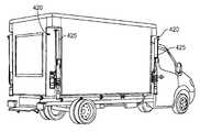
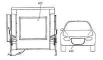
様々な実施の形態において、本明細書の運搬可能なX線検査システムは、車両と共に使用できる。車両はシステムを即座に再配置できまた容易に運搬できる。図2Aは、本明細書のX線検査システムであって、一つの調査地点から別の調査地点に高速で走る車両204の後部荷台に積載することのできる箱体202に収容されたX線検査システムを示す。ある実施の形態では、箱体202に収容されたX線検査システムの重量は、調査地点の特定のセンサ構造や総合的な遮蔽の条件にもよるが、100キロから4500キロの範囲である。 In various embodiments, the transportable X-ray inspection system herein can be used with a vehicle. The vehicle can immediately reposition the system and can be easily transported. FIG. 2A is an X-ray inspection system of the present specification, in which an X-ray inspection housed in a
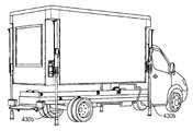
図2Bは、箱体202に収納されたX線検査システムを示し、箱体202は、伸縮可能な脚部206を有する。脚部206は降下して地上面まで引き出され、X線検査システムの全重量を支持する。伸縮可能な脚部206は、輸送用車両204の後部荷台からX線検査システムを持ち上げるか、後部荷台上に載せるように用いられる。 FIG. 2B shows an X-ray inspection system housed in a
様々な実施の形態において、伸縮可能な脚部の態様は様々であり、機械式、水圧式、空気圧式などのような推進運動形態のものである。これらの対応は本明細書の範囲内としてカバーされる。 In various embodiments, the aspect of the extendable leg is various and is of a propulsion motion type such as mechanical, hydraulic, pneumatic or the like. These correspondences are covered within the scope of this specification.
ある実施の形態では、伸縮可能な脚部206の高さが調整可能であり、その結果X線検査システムが地上から所望の高さに保持できて、通過する車両や貨物の検査の便宜に供する。ある実施の形態では、検査対象に対するX線検査システムが最適な高さに保持できることに加えて、X線検査システムの(沿直面における)視野を必要な視野にだけ調整可能にして、周囲環境全体へのX線被爆を最小化している。ある実施の形態では、最初に3点スイッチのようなマルチポイントスイッチを用いてX線検査システムについての必要な高さ設定を行い、次いで上昇又は下降ボタンのようなボタンを作動させて設定された高さまで検査システムを移動させることにより、視野についての手動調整が行われる。別の実施の形態では、近づいてくる検査対象のビデオ解析に基づいて、視野が自動調整される。 In one embodiment, the height of the
ある実施の形態では、伸縮可能な脚部206の最適な高さを決定するために、検査対象の大きさ、所望の検査場所、検出器の列の構成、所望の視野、X線ソースの種類、X線ソースの形態、及び又は抑制構造または人の有無などの複数のデータに基づいて、コントローラによる処理がなされる。脚部206を特に用いない場合には、プラットフォーム又は支持構造の高さを制御するためにコントローラが用いられても良い。当業者にとっては、検査対象や調査地点に応じて、複数のデータが扱われる場合があることも理解されるであろう。 In one embodiment, to determine the optimal height of the
調査地点でのX線検査システムのスキャン動作が完了すると、伸縮可能な脚部を用いて、箱体に収納されたX線検査システムは輸送車両の後部荷台に再積載され、別の調査地点に即座に輸送される。ある実施の形態では、X線検査システムは一般用車両に牽引されたトレーラに積載されて、一つの調査地点から別の調査地点に輸送される。本発明による検査システムの設置や再積載については、図4A乃至図4Qを参照しつつ後述されている。 When the scanning operation of the X-ray inspection system at the survey point is completed, the X-ray inspection system housed in the box using the extendable legs is reloaded on the rear loading platform of the transport vehicle and moved to another survey point. Shipped immediately. In one embodiment, the X-ray inspection system is loaded onto a trailer pulled by a general vehicle and transported from one survey point to another. The installation and reloading of the inspection system according to the present invention will be described later with reference to FIGS. 4A to 4Q.
図3は、互いに異なる高さ310,311、312の車両又は対象325をスキャンするために、地上からの互いに異なる高さ205、306、307に位置する検査コンテナ300を示す。更に、ある実施の形態では、検査コンテナ300は、検査対象又は車両から距離315をおいて位置している。更に、ある実施の形態では、検査対象の車両又は物体に応じて、検査コンテナ300は視野320を変化させることができる。 FIG. 3 shows a
ある実施の形態では、車両325は、高さ310がほぼ4000ミリのトラックであり、検査コンテナ300は地上から1200ミリの高さ305に位置している。更にこの検査コンテナは、車両からの距離315が1500ミリである。この構成によって、全体の視野320が88度となる。 In one embodiment, the
別の実施の形態では、車両325は、高さ311がほぼ3000ミリのバンであり、検査コンテナ300は地上から900ミリの高さ306に位置している。更にこの検査コンテナは、車両からの距離315が950ミリである。この構成によって、全体の視野320が87度となる。 In another embodiment, the
更に別の実施の形態では、車両325は、高さ312がほぼ1800ミリの乗用車であり、検査コンテナ300は地上から600ミリの高さ307に位置している。更にこの検査コンテナは、車両からの距離315が400ミリである。この構成によって、全体の視野320が86度となる。 In yet another embodiment, the
上述した構成は一例であり、対象物のスキャンを達成するように調整がなされることは当業者にとって明らかである。 It will be apparent to those skilled in the art that the configuration described above is an example and that adjustments are made to achieve scanning of the object.
図4A乃至4Qは、本明細書の検査システムを示す現場の斜視図であり、このシステムは、箱体のようなコンテナ又はコンパートメントに収容され、輸送車両から調査地点に設置され、次いで輸送車両の後部荷台に再積載される。 4A-4Q are perspective views of the field showing the inspection system herein, which is housed in a container or compartment such as a box, installed from the transport vehicle at the survey point, and then the transport vehicle. Reloaded on the rear loading platform.
図4Aは、コンテナ405に収容され、輸送車両415のトレイラ部410に載せられた本明細書によるX線検査システムを示す。ある実施の形態では、輸送車両415はトラックであり、通常の速度で平面道路上や高速道路上を輸送するのに適している。本発明の実施の形態によれば、コンテナ405は4つの鉛直壁面406を有し、実質的に四角の箱体を形成している。更に、コンテナ405は、4つの角部のそれぞれに鉛直方向に延びる凹部420を有し、計4つの凹部420を有する。積載位置にあるときに、それぞれの脚部425は、それぞれの鉛直凹部420に収容され、収容状態では脚部はコンテナ405の鉛直壁面406と面一かまたは壁面よりも内方に凹部内に沈んで位置する。 FIG. 4A shows an X-ray inspection system according to this specification housed in a
設置位置ではそれぞれの脚部425は、コンテナ405のそれぞれの角部から水平方向に延びることができ、また鉛直方向にも伸縮自在に上下に延びることができ、地上からのコンテナ405の台座の高さを可変に設定できるようにしている。調査地点に設置するために、図4Bに示されるように、少なくとも一つの脚部425は、最初に鉛直凹部420から水平方向外方に延ばされる。ここで、全ての脚部が水平方向に延ばされることは必ずしも要求されない。これは、延ばされた脚部間で、トレーラの車輪が通過できる程度の隙間の必要性に応じればよい。次に、複数の脚部425は、鉛直方向下方に延ばされる。図4Cは、第1の中間鉛直脚部位置又は伸縮可能に延ばされた脚部位置430aを示し、図4Dは、第2の中間鉛直脚部位置又は伸縮可能に延ばされた脚部位置430bを示し、図4Dにおいては、延びた脚部位置430bにおいては,脚部425は地面に接触している。 In the installation position, each
図4Eは、水平方向に延びた位置におけるピストン426を示す近接図であり、この位置では、水平方向に延びた脚部425は鉛直凹部420の外側に位置する。脚部425が鉛直方向下方にも延びたときには脚部を目視でき、図4Dの位置430bのような鉛直方向に延びた脚部の位置であることがわかる。 FIG. 4E is a close-up view showing the
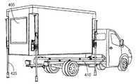
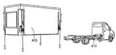
図4Fに示されるように、(脚部425が地面に接触している)図4Dの脚部位置430bを越えて、脚部425は更に鉛直方向下方に延び、その結果コンテナ405はトレーラ410のシャーシから上昇する。コンテナ405が最適の高さに位置して4本の脚部425全てが地面に接触すると、図4Gに示されるように、トレーラ410はコンテナ405の下側から遠ざかるようになる。 As shown in FIG. 4F, beyond the
その結果、図4Hに示されるように、調査地点において、コンテナ405は第1の高さで、十分に延びた脚部425の上に設置される。そして、スキャンのために、脚部425の鉛直方向の伸縮運動を用いて、地上からのコンテナ405の台座の高さが調整される。図4Iは、第2の鉛直方向後退位置にある脚部425を示し、コンテナ405を第2の高さに位置させている。また図4Jは、第3の鉛直方向後退位置にある脚部425を示し、コンテナ405を第3の高さに位置させている。ひとたび地上に設置されれば、脚部425を鉛直方向に後退させるか延ばして、コンテナ405を降下させるか上昇させ、地上からのコンテナ405の位置を変化させて、様々なスキャン高さを提供することは、当業者にとって理解されることである。図4H乃至4Jに示されるコンテナ405の第1、第2、第3の高さは、図3に示されるコンテナの高さ305、306、307にそれぞれ対応する。 As a result, as shown in FIG. 4H, at the survey point, the
脚部425を鉛直方向に後退させるか延ばすことでコンテナ405の高さを所望の位置にした後は、対象の物体又は車両をスキャンできる。例えば、図4Kでは、コンテナ405を適切な高さに位置させて、通過する乗用車435をスキャンし、乗用車435のX線スキャン像を生成する。 After the height of the
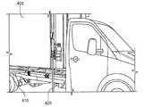
図4Lにおいて、別の場所に輸送し又は再設置するために、コンテナ405はトレーラ410に積載されるか再積載される必要がある。しかして、トレーラ410は、調査地点に設置されているコンテナ405の下に位置するように操縦される。必要であれば、脚部425を鉛直方向に延ばすことで、コンテナ405の高さを調整し、トレーラ410が何ら妨げられることなくコンテナ405の下側に位置できるように操縦される。トレーラ410をコンテナ405の下側に位置させるために輸送車両を背走中に、コンテナ405の下側にトレーラ410を安全に位置させるため、また輸送車両がコンテナに間違って衝突するのを避けるために、複数の予防手段が設けられる。例えば以下の例がある。(a)輸送車両にリヤビューカメラを設ける、(b)運転室の後ろに金属製のバッファを設けて、運転手が位置を知るようにする、(c)コンテナ405(背走する輸送車両に面するコンテナ405の壁)に、位置センサを設ける。この場合、トレーラ410にコンテナ405を再積載するための正しい位置の近くに輸送車両が近づいたときに、位置センサが作動する。 In FIG. 4L, the
ひとたびトレーラ410がコンテナ405の下側に位置すると、図4Mに示されるように脚部425は鉛直方向で後退して、コンテナ405は次第にトレーラ410に向かって降下する。図4Nは、コンテナ405がトレーラ410上に積載された状態を示す。トレーラ410に積載されれば、脚部425は十分に鉛直方向で後退し、その後、脚部425は水平方向に後退して鉛直凹部420内に位置する。 Once the
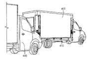
本発明の一つの観点によれば、コンテナを静止したトレーラ上に載せたままで、(例えば車両のような)移動標的についても、スキャンの対象とすることができる。図4Oは、静止したトレーラ410上に載せられたコンテナ405を示し、トラック445がトレーラのそばを通り過ぎている。通過するトラック445はスキャンを受け、それのX線画像が生成される。ある実施の形態では、トレーラ410に積載されたコンテナ405の高さは、図3の高さ306に対応する。 According to one aspect of the present invention, a moving target (such as a vehicle) can be a target for scanning while the container is placed on a stationary trailer. FIG. 4O shows a
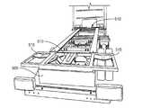
X線検査システムを内蔵するコンテナが、輸送中にトレーラのシャーシ上に安全に積載されるようにし、またシャーシにコンテナが積載された状態で対象物のスキャンをできるようにするために、トレーラのシャーシには適切な装備が設けられている。ある実施の形態では、図5Aに示されるように、トレーラのシャーシ505には、シャーシの前端部と後端部に設けられた一対のコンテナ載置ブラケット510と、それぞれがシャーシ505の角部に位置する4個のV字形状のコンテナ位置決め板515を有する。図5Bに示されるように、4個の位置決め板515とそれらに対応する(コンテナ525の台座に設けられている)ローラ520とにより、コンテナ525がシャーシ505上に向かって下降たときに、コンテナ525が前後の載置ブラケット510と整合する位置になるようにしている。ある実施の形態では、コンテナ525がシャーシ505上に積載された後に、4本の脚部530が機内方向に移動して収容位置に位置し、4本の脚部アセンブリ530のそれぞれに位置する角付き板535によって脚部が所定の位置に保持される。それぞれの脚部530の機内側端部にある角付き板535は、載置ブラケット510の側方のそれぞれにあるクレードル内に位置し、コンテナ525がシャーシ上505で積載されている状態を確保する。 To ensure that the container containing the X-ray inspection system is safely loaded onto the trailer chassis during transport and to allow the object to be scanned with the container loaded on the chassis. The chassis is equipped with appropriate equipment. In one embodiment, as shown in FIG. 5A, the
図6は、本明細書の検査システムに用いられる公知の放射ソースと検出器アセンブリ600を示す概略図である。ある実施の形態では、アセンブリ600は回転ディスクの形態をなすX線ソース602を有する。スキャンの対象として、トラックまたは大型貨物自動車604が示されている。ある実施の形態では、検出器606と放射源とは、トラックまたは大型貨物自動車の同一側に位置する。放射源はどの時点においても(即ち、一回の放射毎に)対象の単一な領域を照射するように構成される。放射源は、密な平行ペンシルビームを生成し、ビームは物体604の一点を照射する。放射線610はあらゆる方向に分散し、検出器606で検出される。放射中の物体の一点についての情報を得るために、検出器606は、一回の放射ごとの放射線の量を測定する。 FIG. 6 is a schematic diagram illustrating a known radiation source and
別の実施の形態では、本明細書の検査システムに用いられるX線ソースは、多要素散乱コリメータを備え、スキャンされるべき物体を照射するためのX線ファンビームを生成する。物体からの後方散乱X線は、多要素コリメータの後方に位置するセグメント化された検出器列で検出される。ここで一つの検出器要素は、一つのコリメータ要素に対応している。このようなX線ソースは本出願人による米国出願第13/368,202号に記載されており、当該出願明細書の内容全体は本出願に援用される。 In another embodiment, the x-ray source used in the inspection system herein includes a multi-element scatter collimator to generate an x-ray fan beam for illuminating an object to be scanned. Backscattered X-rays from the object are detected with a segmented detector array located behind the multi-element collimator. Here, one detector element corresponds to one collimator element. Such X-ray sources are described in commonly assigned US application Ser. No. 13 / 368,202, the entire contents of which are incorporated herein by reference.
更に別の本明細書の実施の形態では、X線後方散乱ソース検出器アセンブリが、高強度線形加速器ベースの透過撮像ソース検出器アセンブリと組合される。その目的は、表面X線後方散乱画像と、かさばる物体の透過撮像とを空間的に相互に関連づけるためである。これは荷物中の違法な材料や対象を検出するための更なる捜査である。 In yet another embodiment herein, an x-ray backscatter source detector assembly is combined with a high intensity linear accelerator based transmission imaging source detector assembly. The purpose is to spatially correlate surface X-ray backscattered images and transmission imaging of bulky objects. This is a further investigation to detect illegal materials and objects in the package.
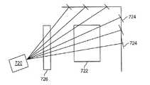
図7Aは、本明細書の実施の形態によるソース検出器アセンブリを示す。ここでは、検査を受ける物体722を通過してX線検出器セット724に向かうコリメートされた高エネルギー(少なくとも900KeV)のファンビーム放射線を発射するために、X線線形加速器(linac)720が用いられる。このX線検出器セット724は、検査対象の高解像透過X線撮像のために用いられる。X線線形加速器ビームはパルス状であり、検査対象がビーム中を移動したとき、複数の一次元画像のセットが得られ、しかる後に互いに重ね合わされて二次元画像が形成される。本実施の形態では、X線後方散乱検出器726は、検査領域の縁部付近であって、検査対象に対しX線線形加速器720と同じ側に位置するが、X線ビームの一方の側にオフセットしており、X線ビームの透過を弱めないようにしている。 FIG. 7A illustrates a source detector assembly according to embodiments herein. Here, an X-ray linear accelerator (linac) 720 is used to emit collimated high-energy (at least 900 KeV) fan beam radiation that passes through the
別の実施の形態では、ソース720が低エネルギX線管ソースでありエネルギは60keV乃至450keVの範囲にある。 In another embodiment,
上述したように、放射線ソースは別の様々な実施の形態において、高エネルギX線、低エネルギX線の他に、ガンマ線、マイクロ波、光線、高周波、ミリ波、テラヘルツ、赤外線、超音波の一つ又は組合せであってもよい。 As described above, the radiation source may be one of gamma rays, microwaves, light beams, high frequency waves, millimeter waves, terahertz waves, infrared rays, ultrasonic waves, in addition to high energy X rays and low energy X rays. One or a combination.
図7Bは、本明細書の別の実施の形態におけるソース検出器アセンブリを示す。主ビームの一方側と他方側にそれぞれ配置された計2個の後方散乱画像検出器726を用いることが有利である。いくつかの実施の形態では、複数の後方散乱検出器は、異なる態様で設けられてもよい。またいくつかの実施の形態では、後方散乱検出器は単一であってもよい。更に別の実施の形態では、3個以上の後方散乱検出器を設けても良い。このような後方散乱ソース検出器アセンブリを用いたX線検査システムは本出願人による米国出願第12/993,831号に記載されており、当該出願明細書の内容全体は本出願に援用される。 FIG. 7B shows a source detector assembly in another embodiment herein. It is advantageous to use a total of two
別の実施の形態では、本明細書は、4つの個別の後方散乱ソース検出器アセンブリを有する多視点ソース検出器アセンブリを提供する。この後方散乱ソース検出器アセンブリは、一つの後方散乱システムからのペンシルビームを再利用して、第2の後方散乱視システムからの大領域の複数の検出器を照射し、多層の同時後方散乱と同じセットの4本のX線ビームを用いたX線透過撮像が達成できる。 In another embodiment, the present specification provides a multi-view source detector assembly having four individual backscatter source detector assemblies. The backscatter source detector assembly reuses the pencil beam from one backscatter system to illuminate multiple large area detectors from a second backscatter vision system, and provides multiple layers of simultaneous backscatter and X-ray transmission imaging using the same set of four X-ray beams can be achieved.
図8は本明細書の実施の形態によるX線検査システムに用いられる多視点X線ソース検出器アセンブリを示す。ある実施の形態では、システム800は、同時に回転する3本のX線ビーム805、806、807と対応する複数の検出器によって可能となった3つの視界を備える。ある実施の形態では、スキャントンネル820を形成した透過構成である。システム800は、本明細書の目的どおりの高度の検査能力を備えており、同時にX線量が実質的に低いものである。なぜなら、画素化した多数のX線検出器やファンビームX線照射を伴う従来のラインスキャンシステムと比較して、時間内のいずれの瞬間においても照射される空間容積が小さいからである。図8に示されるように、同時に収集された3本のX線の視点間では、クロストークがほとんどない。 FIG. 8 illustrates a multi-view X-ray source detector assembly used in an X-ray inspection system according to embodiments herein. In one embodiment,
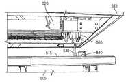
別の実施の形態において多視点スキャンを可能にするために、本発明の放射線検査システムはドライブスルー形式で動作可能である。図9Aと9Bは、検査システムを内蔵したコンテナ905を示しており、外壁910が回動可能であり、天井915が鉛直方向に移動可能である。図9Bに示されるように、コンテナ905が4本の脚部930で調査地点に設置されると、天井915が鉛直方向に上昇し、(図9Aに参照番号が付された)外壁910が下方に回動して、ランプ935が提供され、乗用車のような検査対象車両がランプ935内に、即ちコンテナ605内を通過するように移動できる。 To enable multi-view scanning in another embodiment, the radiation inspection system of the present invention can operate in a drive-through manner. FIGS. 9A and 9B show a
図9Cは、ドライブスルーポータル形式のコンテナ905の概略側断面図を示し、鉛直方向に移動可能な天井915とランプ935を形成する直立姿勢から平らな姿勢になった複数の壁を有する。ある実施の形態では、X線ソース920は天井915に位置し、複数の検出器がコンテナ905内に設けられている。ある実施の形態では、3個の検出器列が戦略的に配置されている。第1の検出器は、床又は台座925に、第2第3の検出器はコンテナ905の2つの固定壁940内に設けられる。更なる実施の形態では、1つ又はそれ以上の検出器は天井915に設けられ、例えばソース920の両側に設けられ、コンテナ905を通過する対象車両の後方散乱像と透過スキャン像の両方を生成できるようにしている。更に別の実施の形態では、付加的な放射線ソースがそれぞれの側壁940に位置し、図8のような多視検査システム800を実現することができる。 FIG. 9C shows a schematic cross-sectional side view of a drive-through
本明細書のひとつの観点によれば、それぞれの検出器セグメント821が常にわずか一つの主X線ビームによって照射される本システム800において、同時に収集できる画像ビューの数にほとんど制限はない。ある実施の形態では、図8に示される検出器830の配列ではそれぞれが1メートルの長さの計12個の検出器セグメント821を備え、幅3メートル、高さ3メートルの検査トンネルを形成している。ある実施の形態の検出器830の配列では、6個の独立したX線視野をサポートすることができ、隣合った検出器の間で、全面的なX線画像ビューの通過が可能となる。別の実施の形態では、長さ0.5mの検出器セグメント821が12個までの独立したX線画像ビューをサポートすることができる。 According to one aspect of the present specification, there is almost no limit to the number of image views that can be acquired simultaneously in the
本明細書のシステム800では、検出器材料の容量は収集されるべき画像ビューの数とは関係がなく、読み出し側の電子機器の密集度は、従来の画素化されたX線検出器列に比較すると極端に低いということは、当業者にとって理解されるべきである。更に複数のX線ソースは、適切な定格の高電圧発生器によって駆動でき、比較的簡単に都合良く付加的なX線ソースを追加することができる。これらの特徴により、本明細書高密度の多視点システム800が実現でき、手荷物検査の場合でも有利に実現可能である。このような多視点X線検査システムは本出願人による米国出願第13/756,211号に記載されており、本明細書に内容が全て援用される。 In the
本明細書による運搬可能なX線検査システムにおいて、複数種類のX線ソース検出器アセンブリが用いられることは当業者にとって自明であり、これらアセンブリの例は、上述したようなソース検出器アセンブリの例に限定されない。 It will be apparent to those skilled in the art that multiple types of X-ray source detector assemblies may be used in the transportable X-ray inspection system according to the present specification, examples of these assemblies are examples of source detector assemblies as described above. It is not limited to.
本明細書による運搬可能なX線検査システムは頑丈な検査システムであり、特殊で高価な輸送用車両を必要とすることなく、一つの調査地点から別の地点に容易に運送することができる。更に、運搬可能なX線検査システムは、輸送のためまた複数の調査地点に容易に設置するために箱体に収納された軽量なシステムである。 The transportable X-ray inspection system according to the present description is a rugged inspection system and can be easily transported from one survey point to another without the need for special and expensive transportation vehicles. Further, the transportable X-ray inspection system is a lightweight system housed in a box for transportation and easy installation at a plurality of survey points.
上記実施の形態は、本発明のシステムの多数の用途を例示したにすぎない。本明細書の実施の形態をいくつか記載したが、本明細書の精神及び範囲から逸脱せずに多数の形態で実施されることを理解すべきである。故に、本発明の実施の形態は、例示であって、限定的に解釈すべきではない。 The above embodiments are merely illustrative of the many uses of the system of the present invention. Although several embodiments of the present specification have been described, it should be understood that the present invention can be embodied in many forms without departing from the spirit and scope of the specification. Therefore, embodiment of this invention is an illustration and should not be interpreted limitedly.
102 検査システム
104 202 箱体
106 ソース・検出器アセンブリ
108 検査ワークステーション
110 センサ
204。415 輸送用車両
206、425 脚部
300 検査コンテナ
325 車両
405、525、605 コンテナ
406 鉛直壁面
410 トレーラ
420 凹部
435 乗用車
445 トラック
505 シャーシ
530 脚部アセンブリ
600 検出器アセンブリ
604 大型貨物自動車
606 検出器
610 放射線
720 ソース
800 多視点システム
821 検出器セグメント
830 検出器
905 コンテナ
910 外壁
915 天井
920 ソース
925 台座
930 脚部
935 ランプ
940 固定壁
940 側壁DESCRIPTION OF
Claims (13)
Translated fromJapanese4つの壁部と、4つの角部と、天井と、基台とで閉ざされた容積を画成するコンテナであって、その収容位置では、車両のトレーラ部に静止して載置されているコンテナと、
該閉ざされた容積内に位置し、放射線の放出により視野を画定する少なくとも一つの放射線ソースと、
該閉ざされた容積内に位置するか又は該コンテナに物理的に付設された少なくとも一つの検出器列と、
それぞれが該4つの角部のそれぞれに位置する4つのピストンであって、それぞれが水平方向に移動することで格納状態から伸張状態になるように構成される4つのピストンと、
それぞれが該コンテナの4つの角部に位置する該4つのピストンのそれぞれに付設された4つの脚部であって、付設された該4つのピストンの移動に基づいてそれぞれが該4つの角部のそれぞれから水平方向外方に伸張可能かつ該4つの角部のそれぞれに格納可能に構成される4つの脚部と、を有し、該4つの脚部のそれぞれは、水平方向外方に伸張されたときに、地面に接触して該コンテナを該トレーラ部から上昇させるように鉛直方向下方に伸張可能であって、地上から少なくともあるひとつの高さ位置に鉛直方向に調整可能であり、該少なくともある一つの高さ位置は、複数のデータを用いて決定されることを特徴とする検査システム。An inspection system for inspecting an inspection object, the inspection systembeing configured to be mounted on a trailer of a vehicle and transported,
A container that defines a volume that is closed byfour walls,four corners, a ceiling, and a base, andis stationaryly placed on a trailer portion of the vehicle at the accommodation position. A container ,
At least one radiation source located within the enclosed volume and defining a field of view by emission of radiation;
At least one detector array located in the closed volume or physically attached to the container;
Four pistons, each positioned at each of the four corners, each configured to move from a retracted state to an extended state by moving horizontally;
Eachafour legs which are attachedto each of the four pistons is located at the four corners of thecontainer, respectively, based on the movement of the attached has been the four pistons are the four corners 's has aretractable configured four legs to each of the possible and the four corners stretched horizontally outwardly from each of therespective saidfourlegs, in a horizontal outward When extended, the container can be extended vertically downward to come into contact with the ground and lift the container from the trailer , andcan be adjusted vertically to at least one height position fromthe ground. The inspection system characterized in that the at least one height position is determined using a plurality of data.
該複数の脚部のうちの少なくとも1本の脚部を該ピストンの少なくとも一つを用いて該コンテナから水平方向外方に伸張し、
複数の脚部のそれぞれを鉛直方向下方に伸張して該複数の脚部のそれぞれを調査地点の地面に接触させ、
該複数の脚部のそれぞれを鉛直方向下方に伸張し続けて該コンテナを該トレーラ部から上昇させ、該コンテナを該複数の脚部で該調査地点に完全に支持し、
該トレーラ部を該調査地点から走りださせることを特徴とする検査システムの設置方法。The four walls, the ceiling, and the base define a closed volume, and the containerplaced on the trailer portion of the transportation vehicle, and the field of view is defined by the emission of radiation located in the closed volume. At least one radiation source and at least one detector array located in the closed volume or physically attached to the container, eachvia a piston in each of the four corners of the container a plurality of legs attachedTe, a method of installing an inspection system having,
Extending at least one leg of the plurality of legs from the container horizontally outwardusing at least one of the pistons ;
Extendingeach of the plurality of legs vertically downward to bringeach of the plurality of legs into contact with the ground at the survey point;
Each of the plurality of legs continues to extend vertically downward to raise the container from the trailer, and the container is fully supported by the plurality of legs at the survey point;
A method for installing an inspection system, characterized in that the trailer unit starts running from the survey point.
Applications Claiming Priority (3)
| Application Number | Priority Date | Filing Date | Title |
|---|---|---|---|
| US201361759211P | 2013-01-31 | 2013-01-31 | |
| US61/759,211 | 2013-01-31 | ||
| PCT/US2014/014198WO2014121097A1 (en) | 2013-01-31 | 2014-01-31 | Portable security inspection system |
Publications (2)
| Publication Number | Publication Date |
|---|---|
| JP2016509223A JP2016509223A (en) | 2016-03-24 |
| JP6385369B2true JP6385369B2 (en) | 2018-09-05 |
Family
ID=51222948
Family Applications (1)
| Application Number | Title | Priority Date | Filing Date |
|---|---|---|---|
| JP2015556177AActiveJP6385369B2 (en) | 2013-01-31 | 2014-01-31 | Transportable safety inspection system |
Country Status (12)
| Country | Link |
|---|---|
| US (3) | US9791590B2 (en) |
| EP (1) | EP2952068B1 (en) |
| JP (1) | JP6385369B2 (en) |
| KR (1) | KR102167245B1 (en) |
| CN (1) | CN105379425B (en) |
| AU (1) | AU2014212158B2 (en) |
| BR (1) | BR112014013226B1 (en) |
| CA (1) | CA2898654C (en) |
| GB (1) | GB2523942B (en) |
| MX (1) | MX350070B (en) |
| PL (1) | PL2952068T3 (en) |
| WO (1) | WO2014121097A1 (en) |
Families Citing this family (74)
| Publication number | Priority date | Publication date | Assignee | Title |
|---|---|---|---|---|
| US7963695B2 (en) | 2002-07-23 | 2011-06-21 | Rapiscan Systems, Inc. | Rotatable boom cargo scanning system |
| US9958569B2 (en) | 2002-07-23 | 2018-05-01 | Rapiscan Systems, Inc. | Mobile imaging system and method for detection of contraband |
| US8223919B2 (en) | 2003-04-25 | 2012-07-17 | Rapiscan Systems, Inc. | X-ray tomographic inspection systems for the identification of specific target items |
| US8243876B2 (en) | 2003-04-25 | 2012-08-14 | Rapiscan Systems, Inc. | X-ray scanners |
| GB0525593D0 (en) | 2005-12-16 | 2006-01-25 | Cxr Ltd | X-ray tomography inspection systems |
| KR101973221B1 (en) | 2011-09-07 | 2019-04-26 | 라피스캔 시스템스, 인코포레이티드 | X-ray inspection system that integrates manifest data with imaging/detection processing |
| JP5917162B2 (en)* | 2012-01-19 | 2016-05-11 | キヤノン株式会社 | X-ray equipment |
| WO2013116549A1 (en) | 2012-02-03 | 2013-08-08 | Rapiscan Systems, Inc. | Combined scatter and transmission multi-view imaging system |
| PE20150237Z (en) | 2012-02-14 | 2015-02-12 | American Science & Eng Inc | X-RAY INSPECTION USING CHANGE OPTICAL FIBER WAVELENGTH COUPLED WITH TWINNER DETECTORS |
| US10670740B2 (en) | 2012-02-14 | 2020-06-02 | American Science And Engineering, Inc. | Spectral discrimination using wavelength-shifting fiber-coupled scintillation detectors |
| US10304137B1 (en) | 2012-12-27 | 2019-05-28 | Allstate Insurance Company | Automated damage assessment and claims processing |
| JP6385369B2 (en) | 2013-01-31 | 2018-09-05 | ラピスカン システムズ、インコーポレイテッド | Transportable safety inspection system |
| GB2532902B (en) | 2013-07-23 | 2020-06-03 | Rapiscan Systems Inc | Methods for improving processing speed for object inspection |
| RO130582B1 (en)* | 2014-01-23 | 2021-12-30 | Mb Telecom Ltd. S.R.L. | System and method for complete and non-intrusive inspection of aircrafts |
| WO2016003547A1 (en) | 2014-06-30 | 2016-01-07 | American Science And Engineering, Inc. | Rapidly relocatable modular cargo container scanner |
| WO2016064913A1 (en)* | 2014-10-21 | 2016-04-28 | Decision Sciences International Corporation | Scalable configurations for multimode passive detection system |
| US9834141B2 (en)* | 2014-10-28 | 2017-12-05 | Nissan North America, Inc. | Vehicle object detection system |
| CN104360416A (en)* | 2014-11-04 | 2015-02-18 | 同方威视技术股份有限公司 | Pull type security check channel |
| CN104459813B (en) | 2014-12-29 | 2019-08-23 | 清华大学 | Vehicular quickly checks system |
| EP3271709B1 (en) | 2015-03-20 | 2022-09-21 | Rapiscan Systems, Inc. | Hand-held portable backscatter inspection system |
| EP3281040B1 (en)* | 2015-04-07 | 2021-11-24 | Shenzhen Xpectvision Technology Co., Ltd. | Semiconductor x-ray detector |
| EP3281039B1 (en)* | 2015-04-07 | 2020-03-11 | Shenzhen Xpectvision Technology Co., Ltd. | Semiconductor x-ray detector |
| CN105146978B (en)* | 2015-07-20 | 2016-08-31 | 中国电子科技集团公司第三十八研究所 | A kind of single set passive type Terahertz environmental control system |
| US10345479B2 (en) | 2015-09-16 | 2019-07-09 | Rapiscan Systems, Inc. | Portable X-ray scanner |
| US20170088041A1 (en)* | 2015-09-25 | 2017-03-30 | Demond Eugene Johnson | Safety Belt Warning Flashers |
| US9604563B1 (en)* | 2015-11-05 | 2017-03-28 | Allstate Insurance Company | Mobile inspection facility |
| CN116309260A (en) | 2016-02-22 | 2023-06-23 | 拉皮斯坎系统股份有限公司 | Method for evaluating average pallet size and density of goods |
| AU2017283553B2 (en) | 2016-06-13 | 2020-01-23 | Decision Sciences International Corporation | Integration of inspection scanners for efficient processing and scanning of cargo containers at a port |
| JP6764709B2 (en)* | 2016-06-30 | 2020-10-07 | 株式会社日立製作所 | X-ray automatic judgment device, X-ray automatic judgment method |
| EP3425115A1 (en)* | 2016-07-28 | 2019-01-09 | Hizen Co., Ltd. | System of inspecting vehicle and method of operating the same |
| KR101932524B1 (en)* | 2016-07-28 | 2019-03-15 | 주식회사 하이젠 | Vehicle check system and controlling method thereof |
| EP3505919B1 (en)* | 2016-08-25 | 2024-07-17 | Beijing Hualixing Technology Development Co., Ltd. | Imaging device for use in vehicle security check and method therefor |
| CN106226338B (en)* | 2016-09-20 | 2023-04-07 | 同方威视技术股份有限公司 | Ray inspection system and inspection method for container |
| US10600609B2 (en) | 2017-01-31 | 2020-03-24 | Rapiscan Systems, Inc. | High-power X-ray sources and methods of operation |
| JP2020516907A (en)* | 2017-04-17 | 2020-06-11 | ラピスキャン・システムズ,インコーポレーテッド | X-ray tomography examination system and method |
| US10416340B2 (en)* | 2017-05-27 | 2019-09-17 | ADANI Systems, Inc. | Autonomous container-transportable system for vehicle scanning |
| CN107323330A (en)* | 2017-06-27 | 2017-11-07 | 吴富强 | A kind of Self-loading-unloading loading space |
| US10585206B2 (en) | 2017-09-06 | 2020-03-10 | Rapiscan Systems, Inc. | Method and system for a multi-view scanner |
| CN107765320B (en)* | 2017-11-24 | 2025-01-10 | 同方威视技术股份有限公司 | Check the system |
| CN108008458B (en)* | 2017-12-29 | 2020-09-08 | 同方威视技术股份有限公司 | Vehicle Backscatter Inspection System |
| CN108227027B (en)* | 2017-12-29 | 2020-12-01 | 同方威视技术股份有限公司 | Vehicle Backscatter Inspection System |
| US20190316885A1 (en)* | 2018-01-18 | 2019-10-17 | Mobile Range Technologies, LLC | Mobile Shooting Range |
| CN108508049B (en)* | 2018-02-08 | 2021-03-26 | 同济大学 | A mobile car chassis security inspection device based on X-ray backscattering |
| CN108398726A (en)* | 2018-05-09 | 2018-08-14 | 清华大学 | Radiation checking system and port facilities |
| EP3811117A4 (en) | 2018-06-20 | 2022-03-16 | American Science & Engineering, Inc. | Wavelength-shifting sheet-coupled scintillation detectors |
| GB2575992A (en)* | 2018-07-31 | 2020-02-05 | 2Xsystems Ltd | Vehicle scanning system |
| CN109406549A (en)* | 2018-12-12 | 2019-03-01 | 北京中百源国际科技创新研究有限公司 | A kind of vehicle-mounted removable safety inspection device |
| CN109490977B (en)* | 2019-01-04 | 2024-12-06 | 清华大学 | Check the equipment |
| CN109521484B (en) | 2019-01-04 | 2024-05-14 | 同方威视技术股份有限公司 | Scanning device and transition method thereof |
| CN109807083A (en)* | 2019-03-18 | 2019-05-28 | 长春光华学院 | A method and system for car seat back recognition based on image analysis |
| CN110145399A (en)* | 2019-06-25 | 2019-08-20 | 烟台杰瑞石油装备技术有限公司 | A mobile power generation system |
| US11753991B2 (en) | 2019-06-25 | 2023-09-12 | Yantai Jereh Petroleum Equipment & Technologies Co., Ltd. | Intake-exhaust transport apparatus mobile power generation system and assembling method thereof |
| CN110327070B (en)* | 2019-07-12 | 2024-07-12 | 山东大骋医疗科技有限公司 | CT apparatus with energy storage system |
| US10830714B1 (en)* | 2019-07-26 | 2020-11-10 | The Boeing Company | Portable X-ray backscattering system |
| ES2804059B2 (en)* | 2019-07-30 | 2021-08-13 | San Jorge Tecnologicas Sl | System and method for detecting objects hidden under a person's clothing |
| US11594001B2 (en) | 2020-01-20 | 2023-02-28 | Rapiscan Systems, Inc. | Methods and systems for generating three-dimensional images that enable improved visualization and interaction with objects in the three-dimensional images |
| US11212902B2 (en) | 2020-02-25 | 2021-12-28 | Rapiscan Systems, Inc. | Multiplexed drive systems and methods for a multi-emitter X-ray source |
| CN111537530A (en)* | 2020-04-24 | 2020-08-14 | 安徽启路达光电科技有限公司 | Micro-dose X-ray foot detector |
| GB2609588B (en) | 2020-06-01 | 2024-11-13 | American Science & Eng Inc | Systems and methods for controlling image contrast in an X-ray system |
| US11193898B1 (en) | 2020-06-01 | 2021-12-07 | American Science And Engineering, Inc. | Systems and methods for controlling image contrast in an X-ray system |
| US11175245B1 (en) | 2020-06-15 | 2021-11-16 | American Science And Engineering, Inc. | Scatter X-ray imaging with adaptive scanning beam intensity |
| US11340361B1 (en) | 2020-11-23 | 2022-05-24 | American Science And Engineering, Inc. | Wireless transmission detector panel for an X-ray scanner |
| WO2022150844A1 (en)* | 2021-01-08 | 2022-07-14 | Viken Detection Corporation | Mobile backscatter imaging system with dual-sided inspection |
| MX2023009276A (en) | 2021-02-23 | 2023-10-10 | Rapiscan Systems Inc | SYSTEMS AND METHODS FOR ELIMINATING CROSSTALK SIGNALS IN ONE OR MORE SCANNING SYSTEMS THAT HAVE MULTIPLE X-RAY SOURCES. |
| EP4298595A4 (en)* | 2021-02-25 | 2025-01-29 | Spinframe Technologies Ltd | SYSTEM AND METHOD FOR AUTOMATIC VEHICLE INSPECTION |
| CN117075215A (en)* | 2021-03-30 | 2023-11-17 | 同方威视技术股份有限公司 | Vehicle-mounted security inspection system |
| WO2023015193A1 (en)* | 2021-08-02 | 2023-02-09 | Rapiscan Holdings, Inc. | Systems and methods to determine a safe time to fire in a vehicle inspection portal |
| GB2624336A (en) | 2021-09-07 | 2024-05-15 | Rapiscan Systems Inc | Methods and systems for accurate visual layer separation in the displays of scanning systems |
| CN115793078B (en)* | 2021-09-09 | 2024-05-21 | 同方威视技术股份有限公司 | Radiation protection device and radiation inspection system |
| CN118235216A (en) | 2021-10-01 | 2024-06-21 | 拉皮斯坎控股公司 | Method and system for concurrently generating multiple substantially similar X-ray beams |
| WO2023150418A2 (en) | 2022-02-03 | 2023-08-10 | Rapiscan Holdings, Inc. | Systems and methods for real-time energy and dose monitoring of an x-ray linear accelerator |
| US20230316488A1 (en)* | 2022-04-04 | 2023-10-05 | Johnson Controls Tyco IP Holdings LLP | Apparatus and system for recording a mail screening process |
| EP4562413A1 (en) | 2022-07-26 | 2025-06-04 | Rapiscan Holdings, Inc. | Methods and systems for performing on-the-fly automatic calibration adjustments of x-ray inspection systems |
| US12140501B1 (en)* | 2024-03-22 | 2024-11-12 | Uveye Ltd. | Single pass automated vehicle inspection system and method |
Family Cites Families (686)
| Publication number | Priority date | Publication date | Assignee | Title |
|---|---|---|---|---|
| US2420845A (en) | 1944-06-15 | 1947-05-20 | Westinghouse Electric Corp | Short exposure x-ray apparatus |
| US3374355A (en) | 1946-02-21 | 1968-03-19 | Atomic Energy Commission Usa | Magnetic focusing of x-ray tubes and system for operating |
| US2636619A (en) | 1950-02-07 | 1953-04-28 | Charles E Alexander | Vehicle hoist |
| US2885069A (en) | 1954-11-19 | 1959-05-05 | William V Bowen | Conveyor belt cleaning apparatus |
| US2831123A (en) | 1956-07-11 | 1958-04-15 | Webster J Daly | X-ray fluoroscopic device |
| US2952790A (en) | 1957-07-15 | 1960-09-13 | Raytheon Co | X-ray tubes |
| US2972430A (en) | 1958-04-14 | 1961-02-21 | Collapsible Van Co | Collapsible shipping van |
| US3056510A (en) | 1958-04-28 | 1962-10-02 | Edward V Garnett | Derrick for vehicles |
| US3073960A (en) | 1958-07-14 | 1963-01-15 | Westinghouse Electric Corp | Teletherapy device |
| US2971433A (en) | 1959-01-07 | 1961-02-14 | Royal H Akin | Transistorized photomultiplier photometer circuit |
| US3032207A (en) | 1960-02-23 | 1962-05-01 | Humboldt Company | Loading boom with adjustable extension arm |
| US3070399A (en) | 1961-02-03 | 1962-12-25 | David L Bartlett | Expandable house trailer |
| US3239706A (en) | 1961-04-17 | 1966-03-08 | High Voltage Engineering Corp | X-ray target |
| US3146349A (en) | 1961-12-01 | 1964-08-25 | Edward D Jordan | Detecting hidden explosives using neutron beams |
| US3275831A (en) | 1963-05-16 | 1966-09-27 | Industrial Nucleonics Corp | Radiation beam shutter collimator |
| US3458026A (en) | 1966-03-28 | 1969-07-29 | Taylor & Gaskin | Article spacer |
| US3485339A (en) | 1967-12-11 | 1969-12-23 | Fairbank Morse Inc | Article spacing system |
| US3676783A (en) | 1968-04-23 | 1972-07-11 | Japan Atomic Energy Res Inst | Waveform discriminating circuit |
| JPS509637B1 (en) | 1970-09-17 | 1975-04-14 | ||
| US3768645A (en) | 1971-02-22 | 1973-10-30 | Sunkist Growers Inc | Method and means for automatically detecting and sorting produce according to internal damage |
| USRE28544E (en) | 1971-07-07 | 1975-09-02 | Radiant energy imaging with scanning pencil beam | |
| US3767850A (en) | 1972-02-22 | 1973-10-23 | Abbott Lab | Graphic recording apparatus and method |
| US3784837A (en) | 1972-05-08 | 1974-01-08 | Siemens Ag | X-ray device with a stand |
| US3766387A (en) | 1972-07-11 | 1973-10-16 | Us Navy | Nondestructive test device using radiation to detect flaws in materials |
| US3837502A (en) | 1973-03-12 | 1974-09-24 | Bucyrus Erie Co | Light weight boom construction |
| US3919467A (en) | 1973-08-27 | 1975-11-11 | Ridge Instr Company Inc | X-ray baggage inspection system |
| DK131955C (en) | 1973-10-09 | 1976-02-23 | I Leunbach | PROCEDURE AND SYSTEM FOR DETERMINING THE ELECTRONITY OF A PART VOLUME OF A BODY |
| US3904923A (en) | 1974-01-14 | 1975-09-09 | Zenith Radio Corp | Cathodo-luminescent display panel |
| GB1497396A (en) | 1974-03-23 | 1978-01-12 | Emi Ltd | Radiography |
| US3980889A (en) | 1974-04-08 | 1976-09-14 | North American Philips Corporation | Article transfer and inspection apparatus |
| US3958377A (en) | 1974-06-25 | 1976-05-25 | Milner Jr Edwin Earl | Lightweight high strength boom construction |
| US3955678A (en) | 1974-08-09 | 1976-05-11 | American Chain & Cable Company, Inc. | Sorting system |
| DE2442809A1 (en) | 1974-09-06 | 1976-03-18 | Philips Patentverwaltung | ARRANGEMENT FOR DETERMINING ABSORPTION IN A BODY |
| USRE32961E (en) | 1974-09-06 | 1989-06-20 | U.S. Philips Corporation | Device for measuring local radiation absorption in a body |
| DE2532218C2 (en) | 1975-07-18 | 1982-09-02 | Heimann Gmbh, 6200 Wiesbaden | Device for checking items of luggage by means of X-rays |
| DE2532300C3 (en) | 1975-07-18 | 1979-05-17 | Heimann Gmbh, 6200 Wiesbaden | System for checking baggage using X-rays |
| GB1526041A (en) | 1975-08-29 | 1978-09-27 | Emi Ltd | Sources of x-radiation |
| NL7611391A (en) | 1975-10-18 | 1977-04-20 | Emi Ltd | ROENTGENTER. |
| US4210811A (en) | 1975-11-03 | 1980-07-01 | Heimann Gmbh | Drive for moveable shield in luggage screening apparatus |
| US4064440A (en) | 1976-06-22 | 1977-12-20 | Roder Frederick L | X-ray or gamma-ray examination device for moving objects |
| DE2647167C2 (en) | 1976-10-19 | 1987-01-29 | Siemens AG, 1000 Berlin und 8000 München | Device for producing tomographic images using X-rays or similar penetrating rays |
| DE2650237C2 (en) | 1976-11-02 | 1985-05-02 | Siemens AG, 1000 Berlin und 8000 München | X-ray diagnostic device for the production of transverse slice images |
| DE2705640A1 (en) | 1977-02-10 | 1978-08-17 | Siemens Ag | COMPUTER SYSTEM FOR THE PICTURE STRUCTURE OF A BODY SECTION AND PROCESS FOR OPERATING THE COMPUTER SYSTEM |
| US4105922A (en) | 1977-04-11 | 1978-08-08 | General Electric Company | CT number identifier in a computed tomography system |
| DE2729353A1 (en) | 1977-06-29 | 1979-01-11 | Siemens Ag | X=ray tube with migrating focal spot for tomography appts. - has shaped anode, several control grids at common potential and separately switched cathode |
| DE2735400C2 (en) | 1977-08-05 | 1979-09-20 | Heimann Gmbh, 6200 Wiesbaden | Device for checking baggage by means of X-rays |
| US4164138A (en) | 1977-10-27 | 1979-08-14 | Smith & Denison | High sensitivity gas leak detection system |
| DE2807735B2 (en) | 1978-02-23 | 1979-12-20 | Philips Patentverwaltung Gmbh, 2000 Hamburg | X-ray tube with a tubular piston made of metal |
| US4228353A (en) | 1978-05-02 | 1980-10-14 | Johnson Steven A | Multiple-phase flowmeter and materials analysis apparatus and method |
| JPS5546408A (en) | 1978-09-29 | 1980-04-01 | Toshiba Corp | X-ray device |
| DE2939146A1 (en) | 1979-09-27 | 1981-04-16 | Philips Patentverwaltung Gmbh, 2000 Hamburg | METHOD FOR EXAMINING A BODY WITH Pervasive RADIATION |
| US4266425A (en) | 1979-11-09 | 1981-05-12 | Zikonix Corporation | Method for continuously determining the composition and mass flow of butter and similar substances from a manufacturing process |
| US4352021A (en) | 1980-01-07 | 1982-09-28 | The Regents Of The University Of California | X-Ray transmission scanning system and method and electron beam X-ray scan tube for use therewith |
| US4366382B2 (en) | 1980-09-09 | 1997-10-14 | Scanray Corp | X-ray line scan system for use in baggage inspection |
| JPS5756740A (en) | 1980-09-22 | 1982-04-05 | Mitsubishi Electric Corp | Object inspecting device |
| GB2089109B (en) | 1980-12-03 | 1985-05-15 | Machlett Lab Inc | X-rays targets and tubes |
| DE3107949A1 (en) | 1981-03-02 | 1982-09-16 | Siemens AG, 1000 Berlin und 8000 München | X-RAY TUBES |
| JPS57175247A (en) | 1981-04-23 | 1982-10-28 | Toshiba Corp | Radiation void factor meter |
| DE3140145A1 (en) | 1981-10-09 | 1983-04-21 | Heimann Gmbh, 6200 Wiesbaden | DEVICE FOR PRODUCING A X-RAY IMAGE OF BODIES |
| DE3214910A1 (en) | 1981-10-26 | 1983-05-26 | Windmöller & Hölscher, 4540 Lengerich | Conveyor band having an intermittent drive |
| DE3145227A1 (en) | 1981-11-13 | 1983-05-19 | Heimann Gmbh, 6200 Wiesbaden | METHOD AND DEVICE FOR EXAMINING THE CONTENT OF CONTAINERS |
| US4420182A (en) | 1981-11-13 | 1983-12-13 | Kaneshiro Edward S | Collapsible trailer |
| US4501011A (en) | 1982-09-22 | 1985-02-19 | General Electric Company | Angulating lateral fluoroscopic suspension |
| FR2534066B1 (en) | 1982-10-05 | 1989-09-08 | Thomson Csf | X-RAY TUBE PRODUCING A HIGH EFFICIENCY BEAM, ESPECIALLY BRUSH-SHAPED |
| JPS5975549A (en) | 1982-10-22 | 1984-04-28 | Canon Inc | x-ray tube |
| US4626688A (en) | 1982-11-26 | 1986-12-02 | Barnes Gary T | Split energy level radiation detection |
| US4599740A (en) | 1983-01-06 | 1986-07-08 | Cable Arthur P | Radiographic examination system |
| US4481403A (en) | 1983-03-04 | 1984-11-06 | Honeywell Inc. | Temperature control of solid state circuit chips |
| US4525854A (en) | 1983-03-22 | 1985-06-25 | Troxler Electronic Laboratories, Inc. | Radiation scatter apparatus and method |
| JPS5916254A (en) | 1983-06-03 | 1984-01-27 | Toshiba Corp | Portable x-ray equipment |
| JPS6015546A (en) | 1983-07-07 | 1985-01-26 | Toshiba Corp | Method for measuring local void ratio distribution |
| JPS6021440A (en) | 1983-07-15 | 1985-02-02 | Toshiba Corp | Method for measuring distribution of local void rate |
| JPS6057762A (en) | 1983-09-08 | 1985-04-03 | Dainippon Screen Mfg Co Ltd | Adjusting method of impress voltage of photomultiplier tube in picture scanning and recording device |
| GB8331866D0 (en) | 1983-11-29 | 1984-01-04 | Sparrow R W | Ramp |
| US4672649A (en) | 1984-05-29 | 1987-06-09 | Imatron, Inc. | Three dimensional scanned projection radiography using high speed computed tomographic scanning system |
| DE3431082A1 (en) | 1984-08-23 | 1986-02-27 | Heimann Gmbh, 6200 Wiesbaden | CIRCUIT ARRANGEMENT FOR THE HIGH VOLTAGE SUPPLY OF A X-RAY TUBE |
| EP0176314B1 (en) | 1984-09-21 | 1992-06-10 | Picker International, Inc. | Radiography system |
| US4817123A (en) | 1984-09-21 | 1989-03-28 | Picker International | Digital radiography detector resolution improvement |
| US4602462A (en) | 1984-11-16 | 1986-07-29 | Altec Industries, Inc. | Boom articulating mechanism for aerial devices |
| US4709382A (en) | 1984-11-21 | 1987-11-24 | Picker International, Inc. | Imaging with focused curved radiation detectors |
| CN1003542B (en) | 1985-03-04 | 1989-03-08 | 海曼股份公司 | X-ray scanner |
| CN85107860A (en) | 1985-04-03 | 1986-10-01 | 海曼股份公司 | The X-ray scanner |
| DE3526015A1 (en) | 1985-07-20 | 1987-01-22 | Philips Patentverwaltung | METHOD FOR DETERMINING THE SPATIAL DISTRIBUTION OF THE SPREAD CROSS SECTIONS FOR ELASTICALLY SCREENED X-RAY RADIATION AND ARRANGEMENT FOR IMPLEMENTING THE METHOD |
| GB8521287D0 (en) | 1985-08-27 | 1985-10-02 | Frith B | Flow measurement & imaging |
| US4789930A (en) | 1985-11-15 | 1988-12-06 | Picker International, Inc. | Energy dependent gain correction for radiation detection |
| DE3764315D1 (en) | 1986-05-28 | 1990-09-20 | Heimann Gmbh | X-RAY SCANNER. |
| US4799247A (en) | 1986-06-20 | 1989-01-17 | American Science And Engineering, Inc. | X-ray imaging particularly adapted for low Z materials |
| US5040199A (en) | 1986-07-14 | 1991-08-13 | Hologic, Inc. | Apparatus and method for analysis using x-rays |
| JPS6321040A (en) | 1986-07-16 | 1988-01-28 | 工業技術院長 | Ultrahigh speed x-ray ct scanner |
| US4809312A (en) | 1986-07-22 | 1989-02-28 | American Science And Engineering, Inc. | Method and apparatus for producing tomographic images |
| GB8623196D0 (en) | 1986-09-26 | 1986-10-29 | Robinson M | Visual screening system |
| JPS63109653A (en) | 1986-10-27 | 1988-05-14 | Sharp Corp | Information registration search device |
| US4979137A (en) | 1986-11-18 | 1990-12-18 | Ufa Inc. | Air traffic control training system |
| US4752948A (en) | 1986-12-01 | 1988-06-21 | University Of Chicago | Mobile radiography alignment device |
| US4866439A (en) | 1987-03-27 | 1989-09-12 | Kraus John H | Explosives detection system for an aircraft |
| US5114662A (en) | 1987-05-26 | 1992-05-19 | Science Applications International Corporation | Explosive detection system |
| US5006299A (en) | 1987-05-26 | 1991-04-09 | Science Applications International Corporation | Explosive detection system |
| US4809857A (en) | 1987-08-10 | 1989-03-07 | Fmc Corporation | Drum rotation indicator |
| US4853595A (en) | 1987-08-31 | 1989-08-01 | Alfano Robert R | Photomultiplier tube having a transmission strip line photocathode and system for use therewith |
| GB8723040D0 (en) | 1987-10-01 | 1987-11-04 | Logan Fenamec Uk Ltd | Separating articles conveyed by conveyor system |
| DE3886334D1 (en) | 1987-10-05 | 1994-01-27 | Philips Patentverwaltung | Arrangement for examining a body with a radiation source. |
| US4831260A (en) | 1987-10-09 | 1989-05-16 | University Of North Caroline At Chapel Hill | Beam equalization method and apparatus for a kinestatic charge detector |
| DE8717508U1 (en) | 1987-10-19 | 1989-01-05 | Heimann Gmbh, 6200 Wiesbaden | X-ray scanner |
| GB2212903B (en) | 1987-11-24 | 1991-11-06 | Rolls Royce Plc | Measuring two phase flow in pipes. |
| US4872188A (en) | 1987-11-27 | 1989-10-03 | Picker International, Inc. | Registration correction for radiographic scanners with sandwich detectors |
| US4825454A (en) | 1987-12-28 | 1989-04-25 | American Science And Engineering, Inc. | Tomographic imaging with concentric conical collimator |
| US4864142A (en) | 1988-01-11 | 1989-09-05 | Penetron, Inc. | Method and apparatus for the noninvasive interrogation of objects |
| US4887604A (en) | 1988-05-16 | 1989-12-19 | Science Research Laboratory, Inc. | Apparatus for performing dual energy medical imaging |
| IT1219311B (en) | 1988-05-18 | 1990-05-03 | Cavanna Spa | DEVICE FOR FORMING GROUPS OF ITEMS PARTICULARLY FOR AUTOMATIC PACKAGING LINES |
| US4879735A (en) | 1988-05-31 | 1989-11-07 | Owens Robert W | Baggage inspection conveyor baffle and method |
| US5007072A (en) | 1988-08-03 | 1991-04-09 | Ion Track Instruments | X-ray diffraction inspection system |
| US4975917A (en) | 1988-09-14 | 1990-12-04 | Harris Blake Corporation | Source of coherent short wavelength radiation |
| DE3909147A1 (en) | 1988-09-22 | 1990-09-27 | Philips Patentverwaltung | ARRANGEMENT FOR MEASURING THE IMPULSE TRANSFER |
| US5025150A (en) | 1988-10-14 | 1991-06-18 | Mk-Ferguson Company | Site survey method and apparatus |
| US5267638A (en) | 1989-02-16 | 1993-12-07 | Rapistan Demag Corporation | Dual-servo control for conveyor induction systems |
| US5016767A (en) | 1989-03-10 | 1991-05-21 | Posi-Plus Technologies Inc. | Boom articulation mechanism with, simultaneously operable, cylinders |
| DE58903297D1 (en) | 1989-04-06 | 1993-02-25 | Heimann Systems Gmbh & Co | MATERIAL TESTING PLANT. |
| DE58902570D1 (en) | 1989-08-09 | 1992-12-03 | Heimann Gmbh | DEVICE FOR TRANSMITTING OBJECTS WITH FAN-SHAPED RADIATION. |
| DE58906047D1 (en)* | 1989-08-09 | 1993-12-02 | Heimann Systems Gmbh & Co | Device for radiating objects by means of fan-shaped radiation. |
| US4979202A (en) | 1989-08-25 | 1990-12-18 | Siczek Aldona A | Support structure for X-ray imaging apparatus |
| US4998270A (en) | 1989-09-06 | 1991-03-05 | General Electric Company | Mammographic apparatus with collimated controllable X-ray intensity and plurality filters |
| US5022062A (en) | 1989-09-13 | 1991-06-04 | American Science And Engineering, Inc. | Automatic threat detection based on illumination by penetrating radiant energy using histogram processing |
| US5179581A (en) | 1989-09-13 | 1993-01-12 | American Science And Engineering, Inc. | Automatic threat detection based on illumination by penetrating radiant energy |
| US5014293A (en) | 1989-10-04 | 1991-05-07 | Imatron, Inc. | Computerized tomographic x-ray scanner system and gantry assembly |
| US5097939A (en) | 1989-11-03 | 1992-03-24 | Shanklin Corporation | Synchronous position product feed system |
| IL92485A0 (en) | 1989-11-28 | 1990-08-31 | Israel Defence | System for simulating x-ray scanners |
| EP0432568A3 (en) | 1989-12-11 | 1991-08-28 | General Electric Company | X ray tube anode and tube having same |
| US5098640A (en) | 1990-01-10 | 1992-03-24 | Science Applications International Corporation | Apparatus and method for detecting contraband using fast neutron activation |
| US5076993A (en) | 1990-01-12 | 1991-12-31 | Science Applications International Corporation | Contraband detection system using direct imaging pulsed fast neutrons |
| US5067145A (en) | 1990-03-16 | 1991-11-19 | Siczek Bernard W | Mobile X-ray apparatus |
| US4991189A (en) | 1990-04-16 | 1991-02-05 | General Electric Company | Collimation apparatus for x-ray beam correction |
| US5086300A (en) | 1990-05-29 | 1992-02-04 | Ashmore George A | Method and system for passive detection of electromagnetic events associated with destructive devices |
| US5202932A (en) | 1990-06-08 | 1993-04-13 | Catawa Pty. Ltd. | X-ray generating apparatus and associated method |
| US5181234B1 (en) | 1990-08-06 | 2000-01-04 | Rapiscan Security Products Inc | X-ray backscatter detection system |
| US5319547A (en) | 1990-08-10 | 1994-06-07 | Vivid Technologies, Inc. | Device and method for inspection of baggage and other objects |
| WO1992003722A1 (en) | 1990-08-15 | 1992-03-05 | Massachusetts Institute Of Technology | Detection of explosives and other materials using resonance fluorescence, resonance absorption, and other electromagnetic processes with bremsstrahlung radiation |
| JPH0726851Y2 (en) | 1990-10-09 | 1995-06-14 | シャープ株式会社 | Solar cell |
| US5247561A (en) | 1991-01-02 | 1993-09-21 | Kotowski Andreas F | Luggage inspection device |
| DE4100297A1 (en) | 1991-01-08 | 1992-07-09 | Philips Patentverwaltung | X-RAY TUBES |
| DE4101544A1 (en) | 1991-01-19 | 1992-07-23 | Philips Patentverwaltung | ROENTGENGERAET |
| DE4103588C1 (en) | 1991-02-06 | 1992-05-27 | Siemens Ag, 8000 Muenchen, De | |
| US5272627A (en) | 1991-03-27 | 1993-12-21 | Gulton Industries, Inc. | Data converter for CT data acquisition system |
| GB2255634A (en) | 1991-05-10 | 1992-11-11 | British Steel Plc | Photomultiplier tube for thickness measurement |
| US5144191A (en) | 1991-06-12 | 1992-09-01 | Mcnc | Horizontal microelectronic field emission devices |
| US5185778A (en) | 1991-08-13 | 1993-02-09 | Magram Martin Y | X-ray shielding apparatus |
| DE69223884T2 (en) | 1991-09-12 | 1998-08-27 | Toshiba Kawasaki Kk | Method and device for generating X-ray computer tomograms and for generating shadow images by means of spiral scanning |
| US5224144A (en) | 1991-09-12 | 1993-06-29 | American Science And Engineering, Inc. | Reduced mass flying spot scanner having arcuate scanning lines |
| US5182764A (en) | 1991-10-03 | 1993-01-26 | Invision Technologies, Inc. | Automatic concealed object detection system having a pre-scan stage |
| US5367552A (en) | 1991-10-03 | 1994-11-22 | In Vision Technologies, Inc. | Automatic concealed object detection system having a pre-scan stage |
| KR960005752B1 (en) | 1991-12-10 | 1996-05-01 | 가부시키가이샤 도시바 | X-ray tube apparatus |
| US5253283A (en) | 1991-12-23 | 1993-10-12 | American Science And Engineering, Inc. | Inspection method and apparatus with single color pixel imaging |
| US5263075A (en) | 1992-01-13 | 1993-11-16 | Ion Track Instruments, Inc. | High angular resolution x-ray collimator |
| GB9200828D0 (en) | 1992-01-15 | 1992-03-11 | Image Research Ltd | Improvements in and relating to material identification using x-rays |
| US5221843A (en) | 1992-04-23 | 1993-06-22 | Alvarez Robert E | Active energy selective x-ray image detection |
| US5237598A (en) | 1992-04-24 | 1993-08-17 | Albert Richard D | Multiple image scanning X-ray method and apparatus |
| DE4215343A1 (en) | 1992-05-09 | 1993-11-11 | Philips Patentverwaltung | Filter method for an X-ray system and arrangement for carrying out such a filter method |
| JP3441455B2 (en) | 1992-05-27 | 2003-09-02 | 株式会社東芝 | X-ray CT system |
| JP2005013768A (en) | 1992-05-27 | 2005-01-20 | Toshiba Corp | X-ray CT system |
| JP3631235B2 (en) | 1992-05-27 | 2005-03-23 | 株式会社東芝 | X-ray CT system |
| DE59203913D1 (en) | 1992-07-20 | 1995-11-09 | Heimann Systems Gmbh & Co | Inspection system for objects. |
| US5966422A (en) | 1992-07-20 | 1999-10-12 | Picker Medical Systems, Ltd. | Multiple source CT scanner |
| DE4228559A1 (en) | 1992-08-27 | 1994-03-03 | Dagang Tan | X-ray tube with a transmission anode |
| US5410156A (en) | 1992-10-21 | 1995-04-25 | Miller; Thomas G. | High energy x-y neutron detector and radiographic/tomographic device |
| US5430787A (en) | 1992-12-03 | 1995-07-04 | The United States Of America As Represented By The Secretary Of Commerce | Compton scattering tomography |
| US5600303A (en) | 1993-01-15 | 1997-02-04 | Technology International Incorporated | Detection of concealed explosives and contraband |
| JPH06277207A (en) | 1993-03-25 | 1994-10-04 | Toshiba Corp | Non-destructive inspection device, X-ray CT data detection device, and X-ray CT image processing device |
| US5321271A (en) | 1993-03-30 | 1994-06-14 | Intraop, Inc. | Intraoperative electron beam therapy system and facility |
| DE4311174C2 (en) | 1993-04-05 | 1996-02-15 | Heimann Systems Gmbh & Co | X-ray inspection system for containers and trucks |
| FR2705786B1 (en) | 1993-05-28 | 1995-08-25 | Schlumberger Ind Sa | Method and device for recognizing certain materials in the composition of an object. |
| FR2705785B1 (en) | 1993-05-28 | 1995-08-25 | Schlumberger Ind Sa | Method for determining the attenuation function of an object with respect to the transmission of a reference thickness of a reference material and device for implementing the method. |
| FR2708751B1 (en) | 1993-07-30 | 1995-10-06 | Schlumberger Ind Sa | Method and device for detecting the presence of an object, comprising a given material, not accessible to view. |
| US5557108A (en) | 1993-10-25 | 1996-09-17 | T+E,Uml U+Ee Mer; T+E,Uml U+Ee May O. | Integrated substance detection and identification system |
| US5417540A (en)* | 1993-11-01 | 1995-05-23 | Cox; Henry | Cargo container handling and transport system |
| US5493596A (en) | 1993-11-03 | 1996-02-20 | Annis; Martin | High-energy X-ray inspection system |
| US5590057A (en) | 1993-12-20 | 1996-12-31 | Atlantic Richfield Company | Training and certification system and method |
| US5666393A (en) | 1994-02-17 | 1997-09-09 | Annis; Martin | Method and apparatus for reducing afterglow noise in an X-ray inspection system |
| US5484049A (en) | 1994-02-22 | 1996-01-16 | United Parcel Service Of America, Inc. | Package measuring system and accumulator |
| US5511104A (en) | 1994-03-11 | 1996-04-23 | Siemens Aktiengesellschaft | X-ray tube |
| US5490196A (en) | 1994-03-18 | 1996-02-06 | Metorex International Oy | Multi energy system for x-ray imaging applications |
| US5467377A (en) | 1994-04-15 | 1995-11-14 | Dawson; Ralph L. | Computed tomographic scanner |
| SE9401300L (en) | 1994-04-18 | 1995-10-19 | Bgc Dev Ab | Rotating cylinder collimator for collimation of ionizing, electromagnetic radiation |
| US5606167A (en) | 1994-07-11 | 1997-02-25 | Miller; Thomas G. | Contraband detection apparatus and method |
| IT1266179B1 (it) | 1994-07-20 | 1996-12-23 | Cavanna Spa | Dispositivo e procedimento per regolare l'avanzamento di articoli, ad esempio in impianti per il confezionamento automatico di prodotti |
| US5602894A (en) | 1994-08-04 | 1997-02-11 | Bardash; Michael J. | Three-dimensional imaging system using laser generated ultrashort x-ray pulses |
| JP3091903B2 (en) | 1994-08-17 | 2000-09-25 | セイコーインスツルメンツ株式会社 | Avalanche photodiode and method of manufacturing the same |
| DE4433133C1 (en) | 1994-09-16 | 1995-12-07 | Siemens Ag | X=ray tube for human tomography |
| DE4436688A1 (en) | 1994-10-13 | 1996-04-25 | Siemens Ag | Spiral computer tomograph for human body investigation |
| US5712926A (en) | 1994-10-20 | 1998-01-27 | Eberhard; Jeffrey Wayne | X-ray computed tomography (CT) system for detecting thin objects |
| US6438201B1 (en) | 1994-11-23 | 2002-08-20 | Lunar Corporation | Scanning densitometry system with adjustable X-ray tube current |
| US5548123A (en) | 1994-12-06 | 1996-08-20 | Regents Of The University Of California | High resolution, multiple-energy linear sweep detector for x-ray imaging |
| US5660549A (en) | 1995-01-23 | 1997-08-26 | Flameco, Inc. | Firefighter training simulator |
| US5661377A (en) | 1995-02-17 | 1997-08-26 | Intraop Medical, Inc. | Microwave power control apparatus for linear accelerator using hybrid junctions |
| DE19510168C2 (en) | 1995-03-21 | 2001-09-13 | Heimann Systems Gmbh & Co | Method and device for determining crystalline and polycrystalline materials in an examination area |
| US5882206A (en) | 1995-03-29 | 1999-03-16 | Gillio; Robert G. | Virtual surgery system |
| AUPN226295A0 (en) | 1995-04-07 | 1995-05-04 | Technological Resources Pty Limited | A method and an apparatus for analysing a material |
| US6216540B1 (en) | 1995-06-06 | 2001-04-17 | Robert S. Nelson | High resolution device and method for imaging concealed objects within an obscuring medium |
| US5638817A (en) | 1995-06-07 | 1997-06-17 | Picker International, Inc. | Gamma camera split collimator collimation method and apparatus |
| US5608774A (en) | 1995-06-23 | 1997-03-04 | Science Applications International Corporation | Portable, digital X-ray apparatus for producing, storing, and displaying electronic radioscopic images |
| JP3527796B2 (en) | 1995-06-29 | 2004-05-17 | 株式会社日立製作所 | High-speed three-dimensional image generating apparatus and method |
| DE19532965C2 (en) | 1995-09-07 | 1998-07-16 | Heimann Systems Gmbh & Co | X-ray inspection system for large-volume goods |
| US5600700A (en) | 1995-09-25 | 1997-02-04 | Vivid Technologies, Inc. | Detecting explosives or other contraband by employing transmitted and scattered X-rays |
| US5642393A (en) | 1995-09-26 | 1997-06-24 | Vivid Technologies, Inc. | Detecting contraband by employing interactive multiprobe tomography |
| US5602890A (en)* | 1995-09-27 | 1997-02-11 | Thermedics Detection Inc. | Container fill level and pressurization inspection using multi-dimensional images |
| EP0800647A1 (en) | 1995-10-03 | 1997-10-15 | Koninklijke Philips Electronics N.V. | Apparatus for simultaneous x-ray diffraction and x-ray fluorescence measurements |
| US7045787B1 (en) | 1995-10-23 | 2006-05-16 | Science Applications International Corporation | Density detection using real time discrete photon counting for fast moving targets |
| US6255654B1 (en) | 1995-10-23 | 2001-07-03 | Science Applications International Corporation | Density detection using discrete photon counting |
| US6507025B1 (en) | 1995-10-23 | 2003-01-14 | Science Applications International Corporation | Density detection using real time discrete photon counting for fast moving targets |
| US6018562A (en) | 1995-11-13 | 2000-01-25 | The United States Of America As Represented By The Secretary Of The Army | Apparatus and method for automatic recognition of concealed objects using multiple energy computed tomography |
| DE19542438C1 (en) | 1995-11-14 | 1996-11-28 | Siemens Ag | X=ray tube with vacuum housing having cathode and anode |
| US5738202A (en) | 1995-12-21 | 1998-04-14 | Sandvik Sorting Systems, Inc. | Methods and apparatus for establishing a desired positional relationship between random-length articles conveyed in single file |
| US6304629B1 (en) | 1996-01-11 | 2001-10-16 | Granville Todd Conway | Compact scanner apparatus and method |
| USRE39396E1 (en) | 1996-02-12 | 2006-11-14 | American Science And Engineering, Inc. | Mobile x-ray inspection system for large objects |
| US5764683B1 (en) | 1996-02-12 | 2000-11-21 | American Science & Eng Inc | Mobile x-ray inspection system for large objects |
| KR100231757B1 (en) | 1996-02-21 | 1999-11-15 | 사쿠마 하지메 | Method and device for controlling attachment of construction machine |
| US5696806A (en) | 1996-03-11 | 1997-12-09 | Grodzins; Lee | Tomographic method of x-ray imaging |
| US5633907A (en) | 1996-03-21 | 1997-05-27 | General Electric Company | X-ray tube electron beam formation and focusing |
| US5642394A (en) | 1996-04-03 | 1997-06-24 | American Science And Engineering, Inc. | Sidescatter X-ray detection system |
| US5699400A (en) | 1996-05-08 | 1997-12-16 | Vivid Technologies, Inc. | Operator console for article inspection systems |
| DE19618749A1 (en) | 1996-05-09 | 1997-11-13 | Siemens Ag | X=ray computer tomograph for human body investigation |
| US5661774A (en) | 1996-06-27 | 1997-08-26 | Analogic Corporation | Dual energy power supply |
| DE69716169T2 (en) | 1996-06-27 | 2003-06-12 | Analogic Corp., Peabody | Detection device for axial transverse and quadrature tomography |
| US6167296A (en) | 1996-06-28 | 2000-12-26 | The Board Of Trustees Of The Leland Stanford Junior University | Method for volumetric image navigation |
| US5638420A (en) | 1996-07-03 | 1997-06-10 | Advanced Research And Applications Corporation | Straddle inspection system |
| US5838759A (en) | 1996-07-03 | 1998-11-17 | Advanced Research And Applications Corporation | Single beam photoneutron probe and X-ray imaging system for contraband detection and identification |
| AU3653797A (en) | 1996-07-12 | 1998-02-09 | American Science And Engineering Inc. | Side scatter tomography system |
| GB2315546A (en) | 1996-07-18 | 1998-02-04 | Imperial College | Luggage scanner |
| EP1015913A1 (en) | 1996-07-22 | 2000-07-05 | American Science & Engineering, Inc. | System for rapid x-ray inspection of enclosures |
| US5763886A (en) | 1996-08-07 | 1998-06-09 | Northrop Grumman Corporation | Two-dimensional imaging backscatter probe |
| EP0825457A3 (en) | 1996-08-19 | 2002-02-13 | Analogic Corporation | Multiple angle pre-screening tomographic systems and methods |
| US5974111A (en) | 1996-09-24 | 1999-10-26 | Vivid Technologies, Inc. | Identifying explosives or other contraband by employing transmitted or scattered X-rays |
| US5949811A (en) | 1996-10-08 | 1999-09-07 | Hitachi Medical Corporation | X-ray apparatus |
| US5940468A (en) | 1996-11-08 | 1999-08-17 | American Science And Engineering, Inc. | Coded aperture X-ray imaging system |
| US5744919A (en) | 1996-12-12 | 1998-04-28 | Mishin; Andrey V. | CW particle accelerator with low particle injection velocity |
| JPH10185842A (en)* | 1996-12-20 | 1998-07-14 | Toshiba Fa Syst Eng Kk | X-ray inspection apparatus |
| JPH10211196A (en) | 1997-01-31 | 1998-08-11 | Olympus Optical Co Ltd | X-ray ct scanner |
| US6037597A (en) | 1997-02-18 | 2000-03-14 | Neutech Systems, Inc. | Non-destructive detection systems and methods |
| US6118850A (en) | 1997-02-28 | 2000-09-12 | Rutgers, The State University | Analysis methods for energy dispersive X-ray diffraction patterns |
| US5912460A (en) | 1997-03-06 | 1999-06-15 | Schlumberger Technology Corporation | Method for determining formation density and formation photo-electric factor with a multi-detector-gamma-ray tool |
| US5859891A (en) | 1997-03-07 | 1999-01-12 | Hibbard; Lyn | Autosegmentation/autocontouring system and method for use with three-dimensional radiation therapy treatment planning |
| US5842578A (en) | 1997-03-27 | 1998-12-01 | Cordeiro; James | Screening apparatus and carrier combination |
| US5802134A (en) | 1997-04-09 | 1998-09-01 | Analogic Corporation | Nutating slice CT image reconstruction apparatus and method |
| US6054712A (en) | 1998-01-23 | 2000-04-25 | Quanta Vision, Inc. | Inspection equipment using small-angle topography in determining an object's internal structure and composition |
| US6058158A (en) | 1997-07-04 | 2000-05-02 | Eiler; Peter | X-ray device for checking the contents of closed cargo carriers |
| WO1999009398A1 (en) | 1997-08-21 | 1999-02-25 | American Science And Engineering, Inc. | X-ray determination of the mass distribution in containers |
| US5802140A (en) | 1997-08-29 | 1998-09-01 | Varian Associates, Inc. | X-ray generating apparatus with integral housing |
| US6081580A (en) | 1997-09-09 | 2000-06-27 | American Science And Engineering, Inc. | Tomographic inspection system |
| US7028899B2 (en) | 1999-06-07 | 2006-04-18 | Metrologic Instruments, Inc. | Method of speckle-noise pattern reduction and apparatus therefore based on reducing the temporal-coherence of the planar laser illumination beam before it illuminates the target object by applying temporal phase modulation techniques during the transmission of the plib towards the target |
| US6137895A (en) | 1997-10-01 | 2000-10-24 | Al-Sheikh; Zaher | Method for verifying the identity of a passenger |
| US5982843A (en) | 1997-10-10 | 1999-11-09 | Analogic Corporation | Closed loop air conditioning system for a computed tomography scanner |
| US5901198A (en) | 1997-10-10 | 1999-05-04 | Analogic Corporation | Computed tomography scanning target detection using target surface normals |
| US5970113A (en) | 1997-10-10 | 1999-10-19 | Analogic Corporation | Computed tomography scanning apparatus and method with temperature compensation for dark current offsets |
| US6256404B1 (en) | 1997-10-10 | 2001-07-03 | Analogic Corporation | Computed tomography scanning apparatus and method using adaptive reconstruction window |
| US6091795A (en) | 1997-10-10 | 2000-07-18 | Analogic Corporation | Area detector array for computer tomography scanning system |
| US5949842A (en) | 1997-10-10 | 1999-09-07 | Analogic Corporation | Air calibration scan for computed tomography scanner with obstructing objects |
| US6031888A (en) | 1997-11-26 | 2000-02-29 | Picker International, Inc. | Fluoro-assist feature for a diagnostic imaging device |
| US6149592A (en) | 1997-11-26 | 2000-11-21 | Picker International, Inc. | Integrated fluoroscopic projection image data, volumetric image data, and surgical device position data |
| JPH11164829A (en) | 1997-12-03 | 1999-06-22 | Toshiba Corp | Mountable helical scan CT system |
| US6005918A (en) | 1997-12-19 | 1999-12-21 | Picker International, Inc. | X-ray tube window heat shield |
| US6056671A (en) | 1997-12-19 | 2000-05-02 | Marmer; Keith S. | Functional capacity assessment system and method |
| US6067344A (en) | 1997-12-19 | 2000-05-23 | American Science And Engineering, Inc. | X-ray ambient level safety system |
| US5987097A (en) | 1997-12-23 | 1999-11-16 | General Electric Company | X-ray tube having reduced window heating |
| DE19802668B4 (en) | 1998-01-24 | 2013-10-17 | Smiths Heimann Gmbh | X-ray generator |
| US6151381A (en) | 1998-01-28 | 2000-11-21 | American Science And Engineering, Inc. | Gated transmission and scatter detection for x-ray imaging |
| US6067366A (en) | 1998-02-11 | 2000-05-23 | Analogic Corporation | Apparatus and method for detecting objects in computed tomography data using erosion and dilation of objects |
| US6108396A (en) | 1998-02-11 | 2000-08-22 | Analogic Corporation | Apparatus and method for correcting object density in computed tomography data |
| US6078642A (en) | 1998-02-11 | 2000-06-20 | Analogice Corporation | Apparatus and method for density discrimination of objects in computed tomography data using multiple density ranges |
| US6128365A (en) | 1998-02-11 | 2000-10-03 | Analogic Corporation | Apparatus and method for combining related objects in computed tomography data |
| US6026143A (en) | 1998-02-11 | 2000-02-15 | Analogic Corporation | Apparatus and method for detecting sheet objects in computed tomography data |
| US6272230B1 (en) | 1998-02-11 | 2001-08-07 | Analogic Corporation | Apparatus and method for optimizing detection of objects in computed tomography data |
| US6317509B1 (en) | 1998-02-11 | 2001-11-13 | Analogic Corporation | Computed tomography apparatus and method for classifying objects |
| US6075871A (en) | 1998-02-11 | 2000-06-13 | Analogic Corporation | Apparatus and method for eroding objects in computed tomography data |
| US6035014A (en) | 1998-02-11 | 2000-03-07 | Analogic Corporation | Multiple-stage apparatus and method for detecting objects in computed tomography data |
| US6076400A (en) | 1998-02-11 | 2000-06-20 | Analogic Corporation | Apparatus and method for classifying objects in computed tomography data using density dependent mass thresholds |
| US6111974A (en) | 1998-02-11 | 2000-08-29 | Analogic Corporation | Apparatus and method for detecting sheet objects in computed tomography data |
| US6026171A (en) | 1998-02-11 | 2000-02-15 | Analogic Corporation | Apparatus and method for detection of liquids in computed tomography data |
| JPH11230918A (en) | 1998-02-12 | 1999-08-27 | Hitachi Medical Corp | X-ray inspection device |
| US6044353A (en) | 1998-03-10 | 2000-03-28 | Pugliese, Iii; Anthony V. | Baggage check-in and security system and method |
| DE19812055C2 (en) | 1998-03-19 | 2002-08-08 | Heimann Systems Gmbh & Co | Image processing for material detection using X-rays |
| US6218943B1 (en) | 1998-03-27 | 2001-04-17 | Vivid Technologies, Inc. | Contraband detection and article reclaim system |
| US6073751A (en) | 1998-03-30 | 2000-06-13 | Siemens Aktiengesellschaft | Automatic equipping unit for electrical assemblies with a belt store unit for discharged components |
| US6094472A (en) | 1998-04-14 | 2000-07-25 | Rapiscan Security Products, Inc. | X-ray backscatter imaging system including moving body tracking assembly |
| US6236709B1 (en) | 1998-05-04 | 2001-05-22 | Ensco, Inc. | Continuous high speed tomographic imaging system and method |
| GB2337032B (en) | 1998-05-05 | 2002-11-06 | Rapiscan Security Products Ltd | Sorting apparatus |
| US6097786A (en) | 1998-05-18 | 2000-08-01 | Schlumberger Technology Corporation | Method and apparatus for measuring multiphase flows |
| US6347132B1 (en) | 1998-05-26 | 2002-02-12 | Annistech, Inc. | High energy X-ray inspection system for detecting nuclear weapons materials |
| US6088423A (en) | 1998-06-05 | 2000-07-11 | Vivid Technologies, Inc. | Multiview x-ray based system for detecting contraband such as in baggage |
| DE19826062B4 (en) | 1998-06-12 | 2006-12-14 | Smiths Heimann Gmbh | Method and device for detecting X-rays |
| US6621888B2 (en) | 1998-06-18 | 2003-09-16 | American Science And Engineering, Inc. | X-ray inspection by coherent-scattering from variably disposed scatterers identified as suspect objects |
| US6442233B1 (en) | 1998-06-18 | 2002-08-27 | American Science And Engineering, Inc. | Coherent x-ray scatter inspection system with sidescatter and energy-resolved detection |
| US6118852A (en) | 1998-07-02 | 2000-09-12 | General Electric Company | Aluminum x-ray transmissive window for an x-ray tube vacuum vessel |
| FI3687U1 (en) | 1998-07-13 | 1998-10-26 | Dino Lift Oy | Product series of trailer lifts |
| US6899540B1 (en) | 1998-07-30 | 2005-05-31 | The United States Of America As Represented By The Secretary Of Transportation | Threat image projection system |
| US6278115B1 (en) | 1998-08-28 | 2001-08-21 | Annistech, Inc. | X-ray inspection system detector with plastic scintillating material |
| EP0984302B1 (en) | 1998-09-04 | 2003-08-20 | YXLON International X-Ray GmbH | Method and apparatus for X-ray examination of luggage |
| US6188745B1 (en) | 1998-09-23 | 2001-02-13 | Analogic Corporation | CT scanner comprising a spatially encoded detector array arrangement and method |
| US6236712B1 (en) | 1998-09-25 | 2001-05-22 | Fluoroscan Imaging Systems, Inc. | Miniature C-arm apparatus with multiple x-ray indicators |
| US6183139B1 (en) | 1998-10-06 | 2001-02-06 | Cardiac Mariners, Inc. | X-ray scanning method and apparatus |
| US6021174A (en) | 1998-10-26 | 2000-02-01 | Picker International, Inc. | Use of shaped charge explosives in the manufacture of x-ray tube targets |
| US6301326B2 (en) | 1998-11-02 | 2001-10-09 | Perkinelmer Detection Systems, Inc. | Sheet detection system |
| US6200024B1 (en) | 1998-11-27 | 2001-03-13 | Picker International, Inc. | Virtual C-arm robotic positioning system for use in radiographic imaging equipment |
| DE69937067D1 (en) | 1998-11-30 | 2007-10-18 | Invision Technologies Inc | IMPROPER INSPECTION SYSTEM |
| WO2000033059A2 (en) | 1998-11-30 | 2000-06-08 | American Science And Engineering, Inc. | Multiple scatter system for threat identification |
| DE19855213C2 (en) | 1998-11-30 | 2001-03-15 | Siemens Ag | X-ray device |
| US6453007B2 (en) | 1998-11-30 | 2002-09-17 | American Science And Engineering, Inc. | X-ray inspection using co-planar pencil and fan beams |
| WO2000033109A1 (en) | 1998-11-30 | 2000-06-08 | American Science And Engineering, Inc. | Fan and pencil beams from a common source for x-ray inspection |
| US7050536B1 (en) | 1998-11-30 | 2006-05-23 | Invision Technologies, Inc. | Nonintrusive inspection system |
| US6249567B1 (en) | 1998-12-01 | 2001-06-19 | American Science & Engineering, Inc. | X-ray back scatter imaging system for undercarriage inspection |
| US6421420B1 (en) | 1998-12-01 | 2002-07-16 | American Science & Engineering, Inc. | Method and apparatus for generating sequential beams of penetrating radiation |
| US6181765B1 (en) | 1998-12-10 | 2001-01-30 | General Electric Company | X-ray tube assembly |
| US6282260B1 (en) | 1998-12-14 | 2001-08-28 | American Science & Engineering, Inc. | Unilateral hand-held x-ray inspection apparatus |
| EP1149282A2 (en) | 1998-12-18 | 2001-10-31 | Symyx Technologies, Inc. | Apparatus and method for characterizing libraries of different materials using x-ray scattering |
| US6125165A (en) | 1998-12-22 | 2000-09-26 | William K. Warburton | Technique for attentuating x-rays with very low spectral distortion |
| EP1147406A1 (en) | 1998-12-22 | 2001-10-24 | American Science & Engineering, Inc. | Unilateral hand-held x-ray inspection apparatus |
| US6032808A (en) | 1998-12-24 | 2000-03-07 | Henson; David W. | Portable, mailbox-mounted, potted plant holder |
| US6195444B1 (en) | 1999-01-12 | 2001-02-27 | Analogic Corporation | Apparatus and method for detecting concealed objects in computed tomography data |
| US6345113B1 (en) | 1999-01-12 | 2002-02-05 | Analogic Corporation | Apparatus and method for processing object data in computed tomography data using object projections |
| US6687333B2 (en) | 1999-01-25 | 2004-02-03 | Vanderbilt University | System and method for producing pulsed monochromatic X-rays |
| US6429578B1 (en) | 1999-01-26 | 2002-08-06 | Mats Danielsson | Diagnostic and therapeutic detector system for imaging with low and high energy X-ray and electrons |
| US6459764B1 (en) | 1999-01-27 | 2002-10-01 | American Science And Engineering, Inc. | Drive-through vehicle inspection system |
| US6246320B1 (en) | 1999-02-25 | 2001-06-12 | David A. Monroe | Ground link with on-board security surveillance system for aircraft and other commercial vehicles |
| US6185272B1 (en) | 1999-03-15 | 2001-02-06 | Analogic Corporation | Architecture for CT scanning system |
| US6256369B1 (en) | 1999-03-31 | 2001-07-03 | Analogic Corporation | Computerized tomography scanner with longitudinal flying focal spot |
| US7767972B2 (en) | 1999-04-14 | 2010-08-03 | Juni Jack E | Single photon emission computed tomography system |
| DE19916664A1 (en) | 1999-04-14 | 2000-10-19 | Heimann Systems Gmbh & Co | X-ray image processing method, involves checking coincidence of matching sides of image markings and ratio of common areas to achieve greater clarity by forming final summation marking |
| US6542754B1 (en) | 1999-05-12 | 2003-04-01 | Cisco Systems, Inc. | Synchronizing clock signals in wireless networks |
| US6456684B1 (en) | 1999-07-23 | 2002-09-24 | Inki Mun | Surgical scanning system and process for use thereof |
| US6546072B1 (en) | 1999-07-30 | 2003-04-08 | American Science And Engineering, Inc. | Transmission enhanced scatter imaging |
| US6356620B1 (en) | 1999-07-30 | 2002-03-12 | American Science & Engineering, Inc. | Method for raster scanning an X-ray tube focal spot |
| US6269142B1 (en) | 1999-08-11 | 2001-07-31 | Steven W. Smith | Interrupted-fan-beam imaging |
| US6713773B1 (en) | 1999-10-07 | 2004-03-30 | Mitec, Inc. | Irradiation system and method |
| US6567496B1 (en) | 1999-10-14 | 2003-05-20 | Sychev Boris S | Cargo inspection apparatus and process |
| US6542578B2 (en) | 1999-11-13 | 2003-04-01 | Heimann Systems Gmbh | Apparatus for determining the crystalline and polycrystalline materials of an item |
| DE19954663B4 (en) | 1999-11-13 | 2006-06-08 | Smiths Heimann Gmbh | Method and device for determining a material of a detected object |
| US6528787B2 (en) | 1999-11-30 | 2003-03-04 | Jeol Ltd. | Scanning electron microscope |
| US6763635B1 (en) | 1999-11-30 | 2004-07-20 | Shook Mobile Technology, Lp | Boom with mast assembly |
| DE19958864A1 (en) | 1999-12-07 | 2001-06-13 | Philips Corp Intellectual Pty | X-ray device |
| JP2001176408A (en) | 1999-12-15 | 2001-06-29 | New Japan Radio Co Ltd | Electron tube |
| US20020038753A1 (en) | 1999-12-30 | 2002-04-04 | Valerian Ursu | Apparatus and method for controlling segmented conveyor system |
| US6418189B1 (en) | 2000-01-24 | 2002-07-09 | Analogic Corporation | Explosive material detection apparatus and method using dual energy information of a scan |
| US6459761B1 (en) | 2000-02-10 | 2002-10-01 | American Science And Engineering, Inc. | Spectrally shaped x-ray inspection system |
| US20050117683A1 (en) | 2000-02-10 | 2005-06-02 | Andrey Mishin | Multiple energy x-ray source for security applications |
| US20080211431A1 (en) | 2000-02-10 | 2008-09-04 | American Science And Engineering, Inc. | Pulse-to-Pulse-Switchable Multiple-Energy Linear Accelerators Based on Fast RF Power Switching |
| US7538325B2 (en) | 2000-02-10 | 2009-05-26 | American Science And Engineering, Inc. | Single-pulse-switched multiple energy X-ray source applications |
| US7010094B2 (en) | 2000-02-10 | 2006-03-07 | American Science And Engineering, Inc. | X-ray inspection using spatially and spectrally tailored beams |
| US7369463B1 (en) | 2000-02-21 | 2008-05-06 | N.V. Organon | Electronic alarm timer for use with a medical regimen |
| JP2001233440A (en) | 2000-02-21 | 2001-08-28 | New Tokyo International Airport Authority | Automatic baggage sorting system |
| WO2001065245A1 (en) | 2000-03-01 | 2001-09-07 | Tsinghua University | Container inspection apparatus |
| US8325871B2 (en) | 2000-03-28 | 2012-12-04 | American Science And Engineering, Inc. | Radiation threat detection |
| US6418194B1 (en) | 2000-03-29 | 2002-07-09 | The United States Of America As Represented By The United States Department Of Energy | High speed x-ray beam chopper |
| JP4161513B2 (en) | 2000-04-21 | 2008-10-08 | 株式会社島津製作所 | Secondary target device and fluorescent X-ray analyzer |
| US6427891B1 (en) | 2000-04-25 | 2002-08-06 | Freightliner Corporation | Vehicle mounted hand truck carrier |
| US6629593B2 (en) | 2000-05-11 | 2003-10-07 | Rapistan Systems Advertising Corp. | Conveyor induction system |
| CA2348150C (en) | 2000-05-25 | 2007-03-13 | Esam M.A. Hussein | Non-rotating x-ray system for three-dimensional, three-parameter imaging |
| US6448564B1 (en) | 2000-05-30 | 2002-09-10 | Gtsd Sub Iii | Apparatus, methods, and systems for assaying materials |
| WO2001094984A2 (en) | 2000-06-07 | 2001-12-13 | American Science And Engineering, Inc. | X-ray scatter and transmission system with coded beams |
| US6446782B1 (en) | 2000-06-16 | 2002-09-10 | Rapistan Systems Advertising Corp. | Shuttle top diverter |
| DE10031025C1 (en) | 2000-06-26 | 2002-03-07 | Gsl Ges Fuer Service Leistunge | Access control device, for secure area e.g. for airport, has two different transport devices feeding objects to common control zone for entry into secure area |
| US6628745B1 (en) | 2000-07-01 | 2003-09-30 | Martin Annis | Imaging with digital tomography and a rapidly moving x-ray source |
| US6829585B1 (en) | 2000-07-06 | 2004-12-07 | General Electric Company | Web-based method and system for indicating expert availability |
| US6839403B1 (en) | 2000-07-24 | 2005-01-04 | Rapiscan Security Products (Usa), Inc. | Generation and distribution of annotation overlays of digital X-ray images for security systems |
| US6434219B1 (en) | 2000-07-24 | 2002-08-13 | American Science And Engineering, Inc. | Chopper wheel with two axes of rotation |
| US6812426B1 (en) | 2000-07-24 | 2004-11-02 | Rapiscan Security Products | Automatic reject unit spacer and diverter |
| GB2365522B (en) | 2000-08-03 | 2005-09-21 | Cambridge Imaging Ltd | Improvements in and relating to material identification using X-rays |
| US6901346B2 (en) | 2000-08-09 | 2005-05-31 | Telos Corporation | System, method and medium for certifying and accrediting requirements compliance |
| US6563906B2 (en) | 2000-08-28 | 2003-05-13 | University Of New Brunswick | X-ray compton scattering density measurement at a point within an object |
| US20020045152A1 (en) | 2000-08-29 | 2002-04-18 | Viscardi James S. | Process for controlled image capture and distribution |
| US6837422B1 (en) | 2000-09-01 | 2005-01-04 | Heimann Systems Gmbh | Service unit for an X-ray examining device |
| DE10044357A1 (en) | 2000-09-07 | 2002-03-21 | Heimann Systems Gmbh & Co | Detector arrangement for the detection of X-rays |
| WO2002056055A2 (en) | 2000-09-29 | 2002-07-18 | Massachusetts Inst Technology | Systems and methods for coded aperture imaging of radiation- emitting sources |
| US20040213378A1 (en) | 2003-04-24 | 2004-10-28 | The University Of North Carolina At Chapel Hill | Computed tomography system for imaging of human and small animal |
| US6876724B2 (en) | 2000-10-06 | 2005-04-05 | The University Of North Carolina - Chapel Hill | Large-area individually addressable multi-beam x-ray system and method of forming same |
| US6980627B2 (en) | 2000-10-06 | 2005-12-27 | Xintek, Inc. | Devices and methods for producing multiple x-ray beams from multiple locations |
| DE60135568D1 (en) | 2000-10-11 | 2008-10-09 | Symetrica Ltd | GAMMASTRAHLENSPEKTROMETRIE |
| US6748043B1 (en) | 2000-10-19 | 2004-06-08 | Analogic Corporation | Method and apparatus for stabilizing the measurement of CT numbers |
| DE10055356A1 (en) | 2000-11-08 | 2002-05-16 | Georg Fischer Moessner Gmbh | Speed level for escalators |
| US6735271B1 (en) | 2000-11-28 | 2004-05-11 | Ge Medical Systems Global Technology Company Llc | Electron beam computed tomographic scanner system with helical or tilted target, collimator, and detector components to eliminate cone beam error and to scan continuously moving objects |
| DE10062214B4 (en) | 2000-12-13 | 2013-01-24 | Smiths Heimann Gmbh | Devices for transilluminating objects |
| US6473487B1 (en) | 2000-12-27 | 2002-10-29 | Rapiscan Security Products, Inc. | Method and apparatus for physical characteristics discrimination of objects using a limited view three dimensional reconstruction |
| WO2002067779A1 (en) | 2001-02-28 | 2002-09-06 | Mitsubishi Heavy Industries, Ltd. | Multi-radiation source x-ray ct apparatus |
| US6324249B1 (en) | 2001-03-21 | 2001-11-27 | Agilent Technologies, Inc. | Electronic planar laminography system and method |
| US6707879B2 (en) | 2001-04-03 | 2004-03-16 | L-3 Communications Security And Detection Systems | Remote baggage screening system, software and method |
| CA2443509A1 (en) | 2001-04-03 | 2002-10-17 | Michael P. Ellenbogen | X-ray inspection system |
| JP4216078B2 (en) | 2001-04-03 | 2009-01-28 | コーニンクレッカ フィリップス エレクトロニクス エヌ ヴィ | Computed tomography apparatus for determining pulse momentum transfer spectrum |
| US6702459B2 (en) | 2001-04-11 | 2004-03-09 | The Uab Research Foundation | Mobile radiography system and process |
| US6477417B1 (en) | 2001-04-12 | 2002-11-05 | Pacesetter, Inc. | System and method for automatically selecting electrode polarity during sensing and stimulation |
| US6813374B1 (en) | 2001-04-25 | 2004-11-02 | Analogic Corporation | Method and apparatus for automatic image quality assessment |
| US6658087B2 (en) | 2001-05-03 | 2003-12-02 | American Science And Engineering, Inc. | Nautical X-ray inspection system |
| US6597760B2 (en) | 2001-05-23 | 2003-07-22 | Heimann Systems Gmbh | Inspection device |
| US6580778B2 (en) | 2001-05-23 | 2003-06-17 | Heimann Systems Gmbh | Inspection device |
| JP4777539B2 (en) | 2001-05-29 | 2011-09-21 | エスアイアイ・ナノテクノロジー株式会社 | Compound X-ray analyzer |
| US6721387B1 (en) | 2001-06-13 | 2004-04-13 | Analogic Corporation | Method of and system for reducing metal artifacts in images generated by x-ray scanning devices |
| DE10129463A1 (en) | 2001-06-19 | 2003-01-02 | Philips Corp Intellectual Pty | X-ray tube with a liquid metal target |
| GB0115615D0 (en) | 2001-06-27 | 2001-08-15 | Univ Coventry | Image segmentation |
| US6663280B2 (en) | 2001-06-28 | 2003-12-16 | Heimann Systems Gmbh | Inspection unit |
| US7505557B2 (en) | 2006-01-30 | 2009-03-17 | Rapiscan Security Products, Inc. | Method and system for certifying operators of x-ray inspection systems |
| US20030023592A1 (en) | 2001-07-27 | 2003-01-30 | Rapiscan Security Products (Usa), Inc. | Method and system for certifying operators of x-ray inspection systems |
| US6661876B2 (en) | 2001-07-30 | 2003-12-09 | Moxtek, Inc. | Mobile miniature X-ray source |
| US6665433B2 (en) | 2001-07-31 | 2003-12-16 | Agilent Technologies, Inc. | Automatic X-ray determination of solder joint and view Delta Z values from a laser mapped reference surface for circuit board inspection using X-ray laminography |
| US6636623B2 (en) | 2001-08-10 | 2003-10-21 | Visiongate, Inc. | Optical projection imaging system and method for automatically detecting cells with molecular marker compartmentalization associated with malignancy and disease |
| DE10139672A1 (en) | 2001-08-11 | 2003-03-06 | Heimann Systems Gmbh & Co | Method and installation for inspecting an object, in particular a piece of luggage |
| CN1185482C (en) | 2001-08-14 | 2005-01-19 | 清华大学 | Aeronautical container/tray article examination system |
| US6636581B2 (en) | 2001-08-31 | 2003-10-21 | Michael R. Sorenson | Inspection system and method |
| DE10143131B4 (en) | 2001-09-03 | 2006-03-09 | Siemens Ag | Method for determining density and atomic number distributions in radiographic examination methods |
| US8502699B2 (en) | 2001-09-28 | 2013-08-06 | Mct Technology, Llc | Integrated detection and monitoring system |
| US7734066B2 (en) | 2003-11-19 | 2010-06-08 | L-3 Communications Security And Detection Systems, Inc. | Security system with distributed computing |
| US20060115109A1 (en) | 2001-10-01 | 2006-06-01 | L-3 Communications Security And Detection Systems, Inc. | Ensuring airline safety while safeguarding personal passenger information |
| US8031903B2 (en) | 2001-10-01 | 2011-10-04 | L-3 Communications Security And Detection Systems, Inc. | Networked security system |
| US20060274916A1 (en) | 2001-10-01 | 2006-12-07 | L-3 Communications Security And Detection Systems | Remote data access |
| US20030085163A1 (en) | 2001-10-01 | 2003-05-08 | Chan Chin F. | Remote data access |
| DE10149254B4 (en) | 2001-10-05 | 2006-04-20 | Smiths Heimann Gmbh | Method and device for detecting a specific material in an object by means of electromagnetic radiation |
| US7760103B2 (en) | 2001-10-26 | 2010-07-20 | Innovative American Technology, Inc. | Multi-stage system for verification of container contents |
| US6895801B1 (en) | 2001-12-11 | 2005-05-24 | Cyterra Corporation | Pressure activated sampling system |
| WO2003051201A2 (en) | 2001-12-14 | 2003-06-26 | Wisconsin Alumni Research Foundation | Virtual spherical anode computed tomography |
| US6542580B1 (en)* | 2002-01-15 | 2003-04-01 | Rapiscan Security Products (Usa), Inc. | Relocatable X-ray imaging system and method for inspecting vehicles and containers |
| JP2003207453A (en) | 2002-01-16 | 2003-07-25 | Hitachi High-Technologies Corp | Fluorescence and phosphorescence measurement equipment |
| GB0201773D0 (en) | 2002-01-25 | 2002-03-13 | Isis Innovation | X-ray diffraction method |
| US6922455B2 (en) | 2002-01-28 | 2005-07-26 | Starfire Industries Management, Inc. | Gas-target neutron generation and applications |
| US6816571B2 (en) | 2002-02-06 | 2004-11-09 | L-3 Communications Security And Detection Systems Corporation Delaware | Method and apparatus for transmitting information about a target object between a prescanner and a CT scanner |
| US6754298B2 (en) | 2002-02-20 | 2004-06-22 | The Regents Of The University Of Michigan | Method for statistically reconstructing images from a plurality of transmission measurements having energy diversity and image reconstructor apparatus utilizing the method |
| US6618466B1 (en) | 2002-02-21 | 2003-09-09 | University Of Rochester | Apparatus and method for x-ray scatter reduction and correction for fan beam CT and cone beam volume CT |
| US6654443B1 (en) | 2002-02-25 | 2003-11-25 | Ge Medical Systems Global Technology Co., Llc | Thermal sensing detector cell for a computed tomography system and method of manufacturing same |
| US6459755B1 (en) | 2002-02-26 | 2002-10-01 | Ge Medical Systems Global Technology Co. Llc | Method and apparatus for administering low dose CT scans |
| US6775348B2 (en) | 2002-02-27 | 2004-08-10 | General Electric Company | Fiber optic scintillator with optical gain for a computed tomography system and method of manufacturing same |
| US6665373B1 (en) | 2002-03-12 | 2003-12-16 | Rapiscan Security Products (Usa), Inc. | X-ray imaging system with active detector |
| US6727506B2 (en) | 2002-03-22 | 2004-04-27 | Malcolm C. Mallette | Method and apparatus for a radiation monitoring system |
| US7142208B2 (en) | 2002-03-23 | 2006-11-28 | Koninklijke Philips Electronics, N.V. | Method for interactive segmentation of a structure contained in an object |
| FR2837930B1 (en) | 2002-03-26 | 2004-05-21 | Commissariat Energie Atomique | TWO-DIMENSIONAL DETECTOR OF IONIZING PARTICLES |
| US6856344B2 (en) | 2002-04-02 | 2005-02-15 | Robert H. Franz | Vehicle undercarriage inspection and imaging method and system |
| US6647095B2 (en) | 2002-04-02 | 2003-11-11 | Ge Medical Systems Global Technology Co., Llc | Method and apparatus for optimizing dosage to scan subject |
| US6760407B2 (en) | 2002-04-17 | 2004-07-06 | Ge Medical Global Technology Company, Llc | X-ray source and method having cathode with curved emission surface |
| US7087902B2 (en) | 2002-04-19 | 2006-08-08 | Rensselaer Polytechnic Institute | Fresnel lens tomographic imaging |
| US20040178339A1 (en) | 2002-04-24 | 2004-09-16 | The Trustees Of Princeton University | Miniature multinuclide detection system and methods |
| US6879657B2 (en) | 2002-05-10 | 2005-04-12 | Ge Medical Systems Global Technology, Llc | Computed tomography system with integrated scatter detectors |
| US20040066889A1 (en) | 2002-06-10 | 2004-04-08 | Swift Roderick D. | Collimator aperture scheduling for enhanced pencil-beam resolution |
| US6965314B2 (en) | 2002-06-12 | 2005-11-15 | Quintell Of Ohio, Llc | Apparatus and method for asynchronously analyzing data to detect radioactive material |
| WO2004001551A2 (en) | 2002-06-20 | 2003-12-31 | Angel Secure Networks, Inc. | Secure detection network system |
| US6754300B2 (en) | 2002-06-20 | 2004-06-22 | Ge Medical Systems Global Technology Company, Llc | Methods and apparatus for operating a radiation source |
| US6770884B2 (en) | 2002-07-11 | 2004-08-03 | Triumf | High resolution 3-D position sensitive detector for gamma rays |
| US7162005B2 (en) | 2002-07-19 | 2007-01-09 | Varian Medical Systems Technologies, Inc. | Radiation sources and compact radiation scanning systems |
| US7486768B2 (en) | 2002-07-23 | 2009-02-03 | Rapiscan Security Products, Inc. | Self-contained mobile inspection system and method |
| US8275091B2 (en) | 2002-07-23 | 2012-09-25 | Rapiscan Systems, Inc. | Compact mobile cargo scanning system |
| US7783004B2 (en)* | 2002-07-23 | 2010-08-24 | Rapiscan Systems, Inc. | Cargo scanning system |
| US7322745B2 (en) | 2002-07-23 | 2008-01-29 | Rapiscan Security Products, Inc. | Single boom cargo scanning system |
| US6843599B2 (en) | 2002-07-23 | 2005-01-18 | Rapiscan, Inc. | Self-contained, portable inspection system and method |
| US7963695B2 (en) | 2002-07-23 | 2011-06-21 | Rapiscan Systems, Inc. | Rotatable boom cargo scanning system |
| US7369643B2 (en) | 2002-07-23 | 2008-05-06 | Rapiscan Security Products, Inc. | Single boom cargo scanning system |
| US8503605B2 (en) | 2002-07-23 | 2013-08-06 | Rapiscan Systems, Inc. | Four sided imaging system and method for detection of contraband |
| US7356115B2 (en) | 2002-12-04 | 2008-04-08 | Varian Medical Systems Technology, Inc. | Radiation scanning units including a movable platform |
| US7103137B2 (en) | 2002-07-24 | 2006-09-05 | Varian Medical Systems Technology, Inc. | Radiation scanning of objects for contraband |
| US6763083B2 (en) | 2002-08-30 | 2004-07-13 | The United States Of America As Represented By The Administrator Of The National Aeronautics And Space Administration | Article screening system |
| US7155812B1 (en) | 2002-09-05 | 2007-01-02 | Sandia Corporation | Method for producing a tube |
| US7062009B2 (en) | 2002-09-12 | 2006-06-13 | Analogic Corporation | Helical interpolation for an asymmetric multi-slice scanner |
| JP4314008B2 (en) | 2002-10-01 | 2009-08-12 | 株式会社東芝 | X-ray CT scanner |
| ATE496291T1 (en) | 2002-10-02 | 2011-02-15 | Reveal Imaging Technologies Inc | COMPACT CT SCANNER FOR LUGGAGE WITH DETECTOR ARRANGEMENTS AT DIFFERENT DISTANCES FROM THE X-RAY SOURCE |
| US7224765B2 (en) | 2002-10-02 | 2007-05-29 | Reveal Imaging Technologies, Inc. | Computed tomography system |
| US7078699B2 (en) | 2002-10-04 | 2006-07-18 | Varian Medical Systems Technologies, Inc. | Imaging apparatus and method with event sensitive photon detection |
| US7203629B2 (en) | 2002-10-09 | 2007-04-10 | State Of Oregon Acting By And Through The Oregon State Board Of Higher Education On Behalf Of Oregon State University | Modeling substrate noise coupling using scalable parameters |
| CN1181336C (en) | 2002-10-16 | 2004-12-22 | 清华大学 | A vehicle-mounted mobile container inspection system |
| JP4093013B2 (en) | 2002-10-23 | 2008-05-28 | 株式会社日立製作所 | Radiation inspection equipment |
| US7042975B2 (en) | 2002-10-25 | 2006-05-09 | Koninklijke Philips Electronics N.V. | Four-dimensional helical tomographic scanner |
| US7099434B2 (en) | 2002-11-06 | 2006-08-29 | American Science And Engineering, Inc. | X-ray backscatter mobile inspection van |
| US20090257555A1 (en) | 2002-11-06 | 2009-10-15 | American Science And Engineering, Inc. | X-Ray Inspection Trailer |
| US7505556B2 (en)* | 2002-11-06 | 2009-03-17 | American Science And Engineering, Inc. | X-ray backscatter detection imaging modules |
| US7023956B2 (en) | 2002-11-11 | 2006-04-04 | Lockheed Martin Corporaiton | Detection methods and system using sequenced technologies |
| JP2004177138A (en) | 2002-11-25 | 2004-06-24 | Hitachi Ltd | Dangerous substance detection device and dangerous substance detection method |
| US7272429B2 (en) | 2002-11-27 | 2007-09-18 | Ge Medical Systems Global Technology Company, Llc | Methods and apparatus for facilitating a reduction in artifacts |
| US7672426B2 (en) | 2002-12-04 | 2010-03-02 | Varian Medical Systems, Inc. | Radiation scanning units with reduced detector requirements |
| US7062011B1 (en) | 2002-12-10 | 2006-06-13 | Analogic Corporation | Cargo container tomography scanning system |
| US7177387B2 (en) | 2003-11-29 | 2007-02-13 | General Electric Company | Self-aligning scintillator-collimator assembly |
| US6993115B2 (en) | 2002-12-31 | 2006-01-31 | Mcguire Edward L | Forward X-ray generation |
| US7166458B2 (en) | 2003-01-07 | 2007-01-23 | Bio Tex, Inc. | Assay and method for analyte sensing by detecting efficiency of radiation conversion |
| US7072434B1 (en) | 2003-01-16 | 2006-07-04 | Analogic Corporation | Carry-on baggage tomography scanning system |
| US6785357B2 (en) | 2003-01-16 | 2004-08-31 | Bio-Imaging Research, Inc. | High energy X-ray mobile cargo inspection system with penumbra collimator |
| US6735279B1 (en) | 2003-01-21 | 2004-05-11 | University Of Florida | Snapshot backscatter radiography system and protocol |
| WO2004065990A1 (en) | 2003-01-23 | 2004-08-05 | Reveal Imaging Technologies, Inc. | System and method for ct scanning of baggage |
| US7317782B2 (en) | 2003-01-31 | 2008-01-08 | Varian Medical Systems Technologies, Inc. | Radiation scanning of cargo conveyances at seaports and the like |
| US7116235B2 (en) | 2003-01-31 | 2006-10-03 | Veritainer Corporation | Inverse ratio of gamma-ray and neutron emissions in the detection of radiation shielding of containers |
| WO2004072685A1 (en) | 2003-02-13 | 2004-08-26 | Philips Intellectual Property & Standards Gmbh | Method and device for examining an object |
| US7149339B2 (en) | 2003-02-25 | 2006-12-12 | Schlumberger Technology Corporation | Non-destructive inspection of downhole equipment |
| US7065175B2 (en) | 2003-03-03 | 2006-06-20 | Varian Medical Systems Technologies, Inc. | X-ray diffraction-based scanning system |
| US6947517B2 (en) | 2003-03-03 | 2005-09-20 | Ge Medical Systems Global Technology Company, Llc | Scintillator array having a reflector with integrated air gaps |
| US6907101B2 (en) | 2003-03-03 | 2005-06-14 | General Electric Company | CT detector with integrated air gap |
| US6933504B2 (en) | 2003-03-12 | 2005-08-23 | General Electric Company | CT detector having a segmented optical coupler and method of manufacturing same |
| US6859514B2 (en) | 2003-03-14 | 2005-02-22 | Ge Medical Systems Global Technology Company Llc | CT detector array with uniform cross-talk |
| US7164750B2 (en) | 2003-03-26 | 2007-01-16 | Smiths Detection, Inc. | Non-destructive inspection of material in container |
| US7116751B2 (en) | 2003-04-02 | 2006-10-03 | Reveal Imaging Technologies, Inc. | System and method for resolving threats in automated explosives detection in baggage and other parcels |
| DE10318194A1 (en) | 2003-04-22 | 2004-11-25 | Siemens Ag | X-ray tube with liquid metal slide bearing |
| US20050058242A1 (en) | 2003-09-15 | 2005-03-17 | Peschmann Kristian R. | Methods and systems for the rapid detection of concealed objects |
| GB0309374D0 (en) | 2003-04-25 | 2003-06-04 | Cxr Ltd | X-ray sources |
| GB0309387D0 (en) | 2003-04-25 | 2003-06-04 | Cxr Ltd | X-Ray scanning |
| GB0309383D0 (en) | 2003-04-25 | 2003-06-04 | Cxr Ltd | X-ray tube electron sources |
| US8451974B2 (en) | 2003-04-25 | 2013-05-28 | Rapiscan Systems, Inc. | X-ray tomographic inspection system for the identification of specific target items |
| GB0309379D0 (en) | 2003-04-25 | 2003-06-04 | Cxr Ltd | X-ray scanning |
| GB0525593D0 (en) | 2005-12-16 | 2006-01-25 | Cxr Ltd | X-ray tomography inspection systems |
| GB0309385D0 (en) | 2003-04-25 | 2003-06-04 | Cxr Ltd | X-ray monitoring |
| US7054408B2 (en) | 2003-04-30 | 2006-05-30 | General Electric Company | CT detector array having non pixelated scintillator array |
| US7112797B2 (en) | 2003-04-30 | 2006-09-26 | General Electric Company | Scintillator having integrated collimator and method of manufacturing same |
| US6934354B2 (en) | 2003-05-02 | 2005-08-23 | General Electric Company | Collimator assembly having multi-piece components |
| US7068749B2 (en) | 2003-05-19 | 2006-06-27 | General Electric Company | Stationary computed tomography system with compact x ray source assembly |
| US7046756B2 (en) | 2003-05-20 | 2006-05-16 | General Electric Company | Rotatable filter for a pre-subject CT collimator having multiple filtering profiles |
| US6968030B2 (en) | 2003-05-20 | 2005-11-22 | General Electric Company | Method and apparatus for presenting multiple pre-subject filtering profiles during CT data acquisition |
| US7092485B2 (en) | 2003-05-27 | 2006-08-15 | Control Screening, Llc | X-ray inspection system for detecting explosives and other contraband |
| CA2528177A1 (en) | 2003-06-05 | 2004-12-16 | Niton Llc | Neutron and gamma ray monitor |
| US6937692B2 (en) | 2003-06-06 | 2005-08-30 | Varian Medical Systems Technologies, Inc. | Vehicle mounted inspection systems and methods |
| US7119553B2 (en) | 2003-06-11 | 2006-10-10 | Konsulteurope Limited Limited Joint Stock Company | Security scanners with capacitance and magnetic sensor arrays |
| US7317390B2 (en) | 2003-06-11 | 2008-01-08 | Quantum Magnetics, Inc. | Screening checkpoint for passengers and baggage |
| US6922460B2 (en) | 2003-06-11 | 2005-07-26 | Quantum Magnetics, Inc. | Explosives detection system using computed tomography (CT) and quadrupole resonance (QR) sensors |
| US6952163B2 (en) | 2003-06-11 | 2005-10-04 | Quantum Magnetics, Inc. | Combined systems user interface for centralized monitoring of a screening checkpoint for passengers and baggage |
| US6928141B2 (en) | 2003-06-20 | 2005-08-09 | Rapiscan, Inc. | Relocatable X-ray imaging system and method for inspecting commercial vehicles and cargo containers |
| GB0314649D0 (en) | 2003-06-24 | 2003-07-30 | Parkes John H | Blast mitigation device for in flight aircraft |
| US6950492B2 (en) | 2003-06-25 | 2005-09-27 | Besson Guy M | Dynamic multi-spectral X-ray projection imaging |
| US6975698B2 (en) | 2003-06-30 | 2005-12-13 | General Electric Company | X-ray generator and slip ring for a CT system |
| US7197172B1 (en) | 2003-07-01 | 2007-03-27 | Analogic Corporation | Decomposition of multi-energy scan projections using multi-step fitting |
| US7045788B2 (en) | 2003-08-04 | 2006-05-16 | Thermo Electron Corporation | Multi-way radiation monitoring |
| US7031434B1 (en) | 2003-08-06 | 2006-04-18 | General Electric Company | Method of manufacturing, and a collimator mandrel having variable attenuation characteristics for a CT system |
| US7492855B2 (en) | 2003-08-07 | 2009-02-17 | General Electric Company | System and method for detecting an object |
| US20050117700A1 (en) | 2003-08-08 | 2005-06-02 | Peschmann Kristian R. | Methods and systems for the rapid detection of concealed objects |
| US6901135B2 (en) | 2003-08-28 | 2005-05-31 | Bio-Imaging Research, Inc. | System for extending the dynamic gain of an X-ray detector |
| US7279120B2 (en) | 2003-09-04 | 2007-10-09 | Intematix Corporation | Doped cadmium tungstate scintillator with improved radiation hardness |
| JP3909048B2 (en) | 2003-09-05 | 2007-04-25 | ジーイー・メディカル・システムズ・グローバル・テクノロジー・カンパニー・エルエルシー | X-ray CT apparatus and X-ray tube |
| US7162285B2 (en) | 2003-09-19 | 2007-01-09 | Raytheon Company | Detector and method for detecting telephone-activated devices in idle state |
| US7039154B1 (en) | 2003-10-02 | 2006-05-02 | Reveal Imaging Technologies, Inc. | Folded array CT baggage scanner |
| US6991371B2 (en) | 2003-10-14 | 2006-01-31 | The Boeing Company | Computed tomography image quality phantom |
| CN100437096C (en) | 2003-10-16 | 2008-11-26 | 清华大学 | Double radiation source frame structure used for container detecting system |
| CN100437097C (en) | 2003-10-16 | 2008-11-26 | 清华大学 | Radiant ray angle adjustable inspection system for container goods/vehicle |
| US6990171B2 (en) | 2003-10-27 | 2006-01-24 | General Electric Company | System and method of determining a user-defined region-of-interest of an imaging subject for x-ray flux management control |
| US6996209B2 (en) | 2003-10-27 | 2006-02-07 | Ge Medical Systems Global Technology Company, Llc | Scintillator coatings having barrier protection, light transmission, and light reflection properties |
| US7076029B2 (en) | 2003-10-27 | 2006-07-11 | General Electric Company | Method and apparatus of radiographic imaging with an energy beam tailored for a subject to be scanned |
| US7068750B2 (en) | 2003-10-27 | 2006-06-27 | General Electric Company | System and method of x-ray flux management control |
| US7068751B2 (en) | 2003-10-27 | 2006-06-27 | General Electric Company | System and method of determining a center of mass of an imaging subject for x-ray flux management control |
| US7065179B2 (en) | 2003-11-07 | 2006-06-20 | General Electric Company | Multiple target anode assembly and system of operation |
| US7081628B2 (en) | 2003-11-10 | 2006-07-25 | Ge Medical Systems Global Technology Company, Llc | Spatially patterned light-blocking layers for radiation imaging detectors |
| US7046768B1 (en) | 2003-11-10 | 2006-05-16 | Inspx Llc | Shutter-shield for x-ray protection |
| US7099435B2 (en) | 2003-11-15 | 2006-08-29 | Agilent Technologies, Inc | Highly constrained tomography for automated inspection of area arrays |
| US7206379B2 (en) | 2003-11-25 | 2007-04-17 | General Electric Company | RF accelerator for imaging applications |
| US7233640B2 (en) | 2003-11-26 | 2007-06-19 | General Electric Company | CT detector having an optical mask layer |
| US7280631B2 (en) | 2003-11-26 | 2007-10-09 | General Electric Company | Stationary computed tomography system and method |
| US20050226364A1 (en) | 2003-11-26 | 2005-10-13 | General Electric Company | Rotational computed tomography system and method |
| CN1627061A (en) | 2003-12-10 | 2005-06-15 | 清华同方威视技术股份有限公司 | Composite movable type system for inspecting container in low target point |
| US7308074B2 (en) | 2003-12-11 | 2007-12-11 | General Electric Company | Multi-layer reflector for CT detector |
| US7260255B2 (en) | 2003-12-23 | 2007-08-21 | Science Applications International Corporation | Measuring linear separations in digital radiographs |
| US7027553B2 (en) | 2003-12-29 | 2006-04-11 | Ge Medical Systems Global Technology Company, Llc | Systems and methods for generating images by using monochromatic x-rays |
| US7250940B2 (en) | 2003-12-31 | 2007-07-31 | Symbol Technologies, Inc. | Touch screen apparatus and method therefore |
| US7133491B2 (en) | 2004-01-15 | 2006-11-07 | Bio-Imaging Research, Inc. | Traveling X-ray inspection system with collimators |
| US7039159B2 (en) | 2004-01-30 | 2006-05-02 | Science Applications International Corporation | Method and system for automatically scanning and imaging the contents of a moving target |
| US7192031B2 (en) | 2004-02-05 | 2007-03-20 | General Electric Company | Emitter array configurations for a stationary CT system |
| US7609807B2 (en) | 2004-02-17 | 2009-10-27 | General Electric Company | CT-Guided system and method for analyzing regions of interest for contraband detection |
| US6990172B2 (en) | 2004-02-19 | 2006-01-24 | General Electric Company | Method and apparatus to determine tube current modulation profile for radiographic imaging |
| US7224769B2 (en) | 2004-02-20 | 2007-05-29 | Aribex, Inc. | Digital x-ray camera |
| US7333587B2 (en) | 2004-02-27 | 2008-02-19 | General Electric Company | Method and system for imaging using multiple offset X-ray emission points |
| US7885375B2 (en) | 2004-02-27 | 2011-02-08 | General Electric Company | Method and system for X-ray imaging |
| CN101833116B (en) | 2004-03-01 | 2012-07-04 | 瓦润医药系统公司 | Special nuclear material examination by neutrons and delayed neutrons |
| US7027554B2 (en) | 2004-03-01 | 2006-04-11 | Invision Technologies, Inc. | Reduced-size apparatus for non-intrusively inspecting an object |
| US7453987B1 (en) | 2004-03-04 | 2008-11-18 | Science Applications International Corporation | Method and system for high energy, low radiation power X-ray imaging of the contents of a target |
| US7742631B2 (en) | 2004-03-12 | 2010-06-22 | Koninklijke Philips Electronics N.V. | Adaptive sampling along edges for surface rendering |
| JP2005295691A (en) | 2004-03-31 | 2005-10-20 | Toyota Motor Corp | Power output device and automobile equipped with the same |
| US7142629B2 (en) | 2004-03-31 | 2006-11-28 | General Electric Company | Stationary computed tomography system and method |
| US7031430B2 (en) | 2004-04-06 | 2006-04-18 | General Electric Company | System and method for detecting objects with differential operators |
| US7317195B2 (en) | 2004-04-08 | 2008-01-08 | Eikman Edward A | Quantitative transmission/emission detector system and methods of detecting concealed radiation sources |
| US7277526B2 (en) | 2004-04-09 | 2007-10-02 | Lyncean Technologies, Inc. | Apparatus, system, and method for high flux, compact compton x-ray source |
| US7809109B2 (en) | 2004-04-09 | 2010-10-05 | American Science And Engineering, Inc. | Multiple image collection and synthesis for personnel screening |
| DK1733213T3 (en) | 2004-04-09 | 2010-05-03 | American Science & Eng Inc | Eliminating cross-talk in a multi-source retransmission inspection portal by ensuring that only one source emits radiation at a time |
| US7244947B2 (en) | 2004-04-13 | 2007-07-17 | Science Applications International Corporation | Neutron detector with layered thermal-neutron scintillator and dual function light guide and thermalizing media |
| US8350747B2 (en) | 2004-04-14 | 2013-01-08 | L-3 Communications Security And Detection Systems, Inc. | Surveillance with subject screening |
| US7973697B2 (en) | 2004-04-14 | 2011-07-05 | L-3 Communications Security And Detection Systems, Inc. | Surveillance systems and methods with subject-related screening |
| US7277577B2 (en) | 2004-04-26 | 2007-10-02 | Analogic Corporation | Method and system for detecting threat objects using computed tomography images |
| US7212113B2 (en) | 2004-05-04 | 2007-05-01 | Lockheed Martin Corporation | Passenger and item tracking with system alerts |
| US20050251397A1 (en) | 2004-05-04 | 2005-11-10 | Lockheed Martin Corporation | Passenger and item tracking with predictive analysis |
| US7356174B2 (en) | 2004-05-07 | 2008-04-08 | General Electric Company | Contraband detection system and method using variance data |
| US6953935B1 (en) | 2004-05-11 | 2005-10-11 | General Electric Company | CT detector fabrication process |
| US7092481B2 (en) | 2004-05-19 | 2006-08-15 | General Electric Company | Direct conversion energy discriminating CT detector |
| US7190757B2 (en) | 2004-05-21 | 2007-03-13 | Analogic Corporation | Method of and system for computing effective atomic number images in multi-energy computed tomography |
| US7136450B2 (en) | 2004-05-26 | 2006-11-14 | Analogic Corporation | Method of and system for adaptive scatter correction in multi-energy computed tomography |
| WO2005119297A2 (en) | 2004-05-27 | 2005-12-15 | L-3 Communications Security And Detection Systems, Inc. | Contraband detection systems using a large-angle cone beam ct system |
| US7251310B2 (en) | 2004-05-27 | 2007-07-31 | L-3 Communications Security And Detection System | Method and apparatus for detecting contraband using radiated compound signatures |
| US7203269B2 (en) | 2004-05-28 | 2007-04-10 | General Electric Company | System for forming x-rays and method for using same |
| US7166844B1 (en) | 2004-06-01 | 2007-01-23 | Science Applications International Corporation | Target density imaging using discrete photon counting to produce high-resolution radiographic images |
| US7486769B2 (en) | 2004-06-03 | 2009-02-03 | Brondo Jr Joseph H | Advanced multi-resonant, multi-mode gamma beam detection and imaging system for explosives, special nuclear material (SNM), high-z materials, and other contraband |
| US7327853B2 (en) | 2004-06-09 | 2008-02-05 | Analogic Corporation | Method of and system for extracting 3D bag images from continuously reconstructed 2D image slices in computed tomography |
| US7762760B2 (en) | 2004-06-24 | 2010-07-27 | Paceco Corp. | Method of operating a cargo container scanning crane |
| US7302083B2 (en) | 2004-07-01 | 2007-11-27 | Analogic Corporation | Method of and system for sharp object detection using computed tomography images |
| US7282727B2 (en) | 2004-07-26 | 2007-10-16 | Retsky Michael W | Electron beam directed energy device and methods of using same |
| US7224763B2 (en) | 2004-07-27 | 2007-05-29 | Analogic Corporation | Method of and system for X-ray spectral correction in multi-energy computed tomography |
| CN101041989A (en) | 2004-08-05 | 2007-09-26 | 邱则有 | Reinforced bar concrete solid load-carrying structural storied building cover |
| WO2007017846A2 (en) | 2005-08-11 | 2007-02-15 | Navotek Medical Ltd. | Localization of a radioactive source |
| CA2513990C (en) | 2004-08-27 | 2010-09-14 | Paul Jacob Arsenault | X-ray scatter image reconstruction by balancing of discrepancies between detector responses, and apparatus therefor |
| US7151447B1 (en) | 2004-08-31 | 2006-12-19 | Erudite Holding Llc | Detection and identification of threats hidden inside cargo shipments |
| US7149278B2 (en) | 2004-09-10 | 2006-12-12 | General Electric Company | Method and system of dynamically controlling shaping time of a photon counting energy-sensitive radiation detector to accommodate variations in incident radiation flux levels |
| US7260174B2 (en) | 2004-09-13 | 2007-08-21 | General Electric Company | Direct conversion energy discriminating CT detector with over-ranging correction |
| US7272208B2 (en) | 2004-09-21 | 2007-09-18 | Ge Medical Systems Global Technology Company, Llc | System and method for an adaptive morphology x-ray beam in an x-ray system |
| US7139367B1 (en) | 2004-09-29 | 2006-11-21 | Khai Minh Le | Time share digital integration method and apparatus for processing X-ray images |
| RO121293B1 (en) | 2004-09-30 | 2007-02-28 | Mb Telecom Ltd. - S.R.L. | Non-intrusive control system and method |
| US20060067471A1 (en) | 2004-09-30 | 2006-03-30 | General Electric Company | Linear array detector system and inspection method |
| US7136451B2 (en) | 2004-10-05 | 2006-11-14 | Analogic Corporation | Method of and system for stabilizing high voltage power supply voltages in multi-energy computed tomography |
| WO2006045019A2 (en) | 2004-10-18 | 2006-04-27 | Technology Management Consulting Services, Inc. | Detector system for traffic lanes |
| US7260171B1 (en) | 2004-10-25 | 2007-08-21 | General Electric Company | Apparatus for acquisition of CT data with penumbra attenuation calibration |
| US7382853B2 (en) | 2004-11-24 | 2008-06-03 | General Electric Company | Method and system of CT data correction |
| CN100427368C (en) | 2004-11-26 | 2008-10-22 | 同方威视技术股份有限公司 | A drag device for container inspection system |
| US8173970B2 (en) | 2005-02-04 | 2012-05-08 | Dan Inbar | Detection of nuclear materials |
| DE102005006895B4 (en) | 2005-02-15 | 2010-11-18 | Siemens Ag | X-ray diagnostic device and method for its regulation |
| GB2424065A (en) | 2005-03-11 | 2006-09-13 | Corus Uk Ltd | Radiation detection apparatus |
| EP1877829A2 (en) | 2005-03-28 | 2008-01-16 | United Technologies Corporation | Vehicle-based threat detection system |
| US7177391B2 (en) | 2005-03-29 | 2007-02-13 | Surescan Corporation | Imaging inspection apparatus |
| US7738687B2 (en) | 2005-04-07 | 2010-06-15 | L-3 Communications Security And Detection Systems, Inc. | Method of registration in a contraband detection system |
| US7130374B1 (en) | 2005-05-11 | 2006-10-31 | University Of Florida Research Foundation, Inc. | Snapshot backscatter radiography (SBR) systems including system having dynamic collimation |
| CN100573116C (en) | 2005-06-01 | 2009-12-23 | 同方威视技术股份有限公司 | A kind of module structure of detector in double arrays that is used for radiant image |
| US20070085010A1 (en) | 2005-06-14 | 2007-04-19 | The Regents Of The University Of California | Scintillator with a matrix material body carrying nano-material scintillator media |
| US7295651B2 (en) | 2005-06-30 | 2007-11-13 | General Electric Company | Stationary computed tomography system and method |
| US20070009088A1 (en) | 2005-07-06 | 2007-01-11 | Edic Peter M | System and method for imaging using distributed X-ray sources |
| US7231017B2 (en) | 2005-07-27 | 2007-06-12 | Physical Optics Corporation | Lobster eye X-ray imaging system and method of fabrication thereof |
| JP5154745B2 (en)* | 2005-09-06 | 2013-02-27 | 株式会社辰巳菱機 | Self-lifting container |
| DE102005049709A1 (en) | 2005-10-18 | 2007-04-26 | Zf Friedrichshafen Ag | four wheel drive |
| US7308073B2 (en) | 2005-10-20 | 2007-12-11 | General Electric Company | X-ray filter having dynamically displaceable x-ray attenuating fluid |
| CN101379415B (en) | 2005-10-24 | 2013-07-17 | 美国科技工程公司 | X-ray inspection based on scatter detection |
| CN101013094B (en) | 2005-11-03 | 2010-12-29 | 清华大学 | Double-array detector modular structure for radiation imaging |
| US7330535B2 (en) | 2005-11-10 | 2008-02-12 | General Electric Company | X-ray flux management device |
| US7283609B2 (en) | 2005-11-10 | 2007-10-16 | General Electric Company | CT detector photodiode having multiple charge storage devices |
| US7809104B2 (en) | 2005-11-11 | 2010-10-05 | L-3 Communications Security and Detection Systems Inc. | Imaging system with long-standoff capability |
| US7215731B1 (en) | 2005-11-30 | 2007-05-08 | General Electric Company | Fast backprojection/reprojection with hexagonal segmentation of image |
| US7197113B1 (en) | 2005-12-01 | 2007-03-27 | General Electric Company | Contactless power transfer system |
| CN100587481C (en) | 2006-12-14 | 2010-02-03 | 清华大学 | A movable cantilever door type container inspection system |
| US7547888B2 (en) | 2005-12-21 | 2009-06-16 | Los Alamos National Security, Llc | Nanocomposite scintillator and detector |
| CN1995993B (en) | 2005-12-31 | 2010-07-14 | 清华大学 | A method and device for scanning matter by utilizing multiple energy radiation |
| CN101000312B (en) | 2006-01-11 | 2010-05-12 | 清华大学 | A large-scale air container cargo inspection system |
| US7649976B2 (en) | 2006-02-10 | 2010-01-19 | The Boeing Company | System and method for determining dimensions of structures/systems for designing modifications to the structures/systems |
| US20070194909A1 (en) | 2006-02-16 | 2007-08-23 | Michael Garfield | Method and apparatus for sensing and detecting physical, biological and chemical characteristics of a person |
| US8213570B2 (en)* | 2006-02-27 | 2012-07-03 | Rapiscan Systems, Inc. | X-ray security inspection machine |
| US20070297560A1 (en) | 2006-03-03 | 2007-12-27 | Telesecurity Sciences, Inc. | Method and system for electronic unpacking of baggage and cargo |
| US7298812B2 (en) | 2006-03-31 | 2007-11-20 | General Electric Company | Image-based material decomposition |
| US7379530B2 (en) | 2006-04-06 | 2008-05-27 | Bae Systems Information And Electronic Systems Integration Inc. | Method and apparatus for the safe and rapid detection of nuclear devices within containers |
| US7319737B2 (en) | 2006-04-07 | 2008-01-15 | Satpal Singh | Laminographic system for 3D imaging and inspection |
| EP2010943A2 (en) | 2006-04-21 | 2009-01-07 | American Science & Engineering, Inc. | X-ray imaging of baggage and personnel using arrays of discrete sources and multiple collimated beams |
| US7551714B2 (en) | 2006-05-05 | 2009-06-23 | American Science And Engineering, Inc. | Combined X-ray CT/neutron material identification system |
| US7526064B2 (en) | 2006-05-05 | 2009-04-28 | Rapiscan Security Products, Inc. | Multiple pass cargo inspection system |
| CN101074935B (en) | 2006-05-19 | 2011-03-23 | 清华大学 | Detector array and its apparatus |
| US7525101B2 (en) | 2006-05-26 | 2009-04-28 | Thermo Niton Analyzers Llc | Neutron and gamma ray monitor |
| US7483511B2 (en) | 2006-06-06 | 2009-01-27 | Ge Homeland Protection, Inc. | Inspection system and method |
| US7965695B2 (en) | 2006-08-09 | 2011-06-21 | Telefonaktiebolaget L M Ericsson (Publ) | Method and apparatus for routing a packet in mobile IP system |
| EP2052591A2 (en) | 2006-08-10 | 2009-04-29 | Philips Intellectual Property & Standards GmbH | Fly wheel electrode of an x-ray tube |
| RU2448342C2 (en) | 2006-08-11 | 2012-04-20 | Эмерикэн Сайэнс Энд Энджиниэринг, Инк. | Object inspection system (versions) |
| US7561666B2 (en) | 2006-08-15 | 2009-07-14 | Martin Annis | Personnel x-ray inspection system |
| KR20090046849A (en) | 2006-08-23 | 2009-05-11 | 아메리칸 사이언스 앤 엔지니어링, 인크. | Scatter Attenuation Tomography Method |
| US20080056432A1 (en) | 2006-08-30 | 2008-03-06 | General Electric Company | Reconstruction of CT projection data |
| US7835486B2 (en) | 2006-08-30 | 2010-11-16 | General Electric Company | Acquisition and reconstruction of projection data using a stationary CT geometry |
| US7492861B2 (en) | 2006-10-13 | 2009-02-17 | Tsinghua University | Apparatus and method for quick imaging and inspecting moving target |
| US7961906B2 (en)* | 2007-01-03 | 2011-06-14 | Science Applications International Corporation | Human detection with imaging sensors |
| US8678471B2 (en)* | 2007-01-19 | 2014-03-25 | Rieco-Titan Products, Inc. | In-line jack |
| US7789258B1 (en)* | 2007-05-07 | 2010-09-07 | The United States Of America As Represented By The Secretary Of The Navy | Mobile self-contained networked checkpoint |
| US7742568B2 (en)* | 2007-06-09 | 2010-06-22 | Spectrum San Diego, Inc. | Automobile scanning system |
| GB0803646D0 (en) | 2008-02-28 | 2008-04-02 | Rapiscan Security Products Inc | Scanning systems |
| US7593510B2 (en) | 2007-10-23 | 2009-09-22 | American Science And Engineering, Inc. | X-ray imaging with continuously variable zoom and lateral relative displacement of the source |
| EP2212902A4 (en) | 2007-11-01 | 2016-12-07 | Rapiscan Systems Inc | Multiple screen detection systems |
| WO2009067394A2 (en) | 2007-11-19 | 2009-05-28 | American Science And Engineering, Inc. | Multiple image collection and synthesis for personnel screening |
| US7800073B2 (en) | 2007-12-03 | 2010-09-21 | General Electric Company | Moldable neutron sensitive compositions, articles, and methods |
| CN101953234B (en)* | 2007-12-19 | 2015-12-02 | 瑞皮斯坎系统股份有限公司 | Rotatable boom cargo scanning system |
| US7741612B2 (en) | 2008-02-07 | 2010-06-22 | General Electric Company | Integrated neutron-gamma radiation detector with optical waveguide and neutron scintillating material |
| GB0803641D0 (en) | 2008-02-28 | 2008-04-02 | Rapiscan Security Products Inc | Scanning systems |
| GB0803644D0 (en) | 2008-02-28 | 2008-04-02 | Rapiscan Security Products Inc | Scanning systems |
| GB0803642D0 (en) | 2008-02-28 | 2008-04-02 | Rapiscan Security Products Inc | Drive-through scanning systems |
| GB0803640D0 (en) | 2008-02-28 | 2008-04-02 | Rapiscan Security Products Inc | Scanning systems |
| EP2283488A4 (en) | 2008-05-08 | 2017-04-26 | L-3 Communications Security and Detection Systems, Inc. | Adaptive scanning in an imaging system |
| GB0809110D0 (en) | 2008-05-20 | 2008-06-25 | Rapiscan Security Products Inc | Gantry scanner systems |
| GB0809107D0 (en) | 2008-05-20 | 2008-06-25 | Rapiscan Security Products Inc | Scannign systems |
| US8150105B2 (en)* | 2008-05-22 | 2012-04-03 | International Electronic Machines Corporation | Inspection using three-dimensional profile information |
| GB0810638D0 (en) | 2008-06-11 | 2008-07-16 | Rapiscan Security Products Inc | Photomultiplier and detection systems |
| JP4553957B2 (en) | 2008-06-18 | 2010-09-29 | 三菱電機株式会社 | Passage selection device for nuclear measurement device in reactor |
| US7970102B2 (en)* | 2008-07-24 | 2011-06-28 | Inspx Llc | Apparatus and method for detecting foreign materials in a container |
| EP2327281B1 (en) | 2008-08-11 | 2017-11-29 | Rapiscan Laboratories, Inc. | Systems and methods for using an intensity-modulated x-ray source |
| CN101413905B (en) | 2008-10-10 | 2011-03-16 | 深圳大学 | X ray differentiation interference phase contrast imaging system |
| US7991117B2 (en) | 2009-01-13 | 2011-08-02 | Varian Medical Systems, Inc. | Apparatus and method to facilitate dynamically adjusting radiation intensity for imaging purposes |
| MX2011012419A (en) | 2009-05-22 | 2012-03-14 | Rapiscan Systems Inc | Compact mobile cargo scanning system. |
| IN2012DN00778A (en) | 2009-07-13 | 2015-06-26 | Rapiscan Systems Inc | |
| EP2457218A2 (en)* | 2009-07-21 | 2012-05-30 | Clear Path Technologies, Inc. | Portable detection apparatus |
| US8300763B2 (en) | 2009-07-24 | 2012-10-30 | Nucsafe, Inc. | Spatial sequenced backscatter portal |
| WO2011059838A1 (en) | 2009-10-29 | 2011-05-19 | Rapiscan Systems, Inc. | Mobile aircraft inspection system |
| US8582720B2 (en) | 2009-12-03 | 2013-11-12 | Rapiscan Systems, Inc. | Time of flight backscatter imaging system |
| WO2011087861A2 (en) | 2009-12-22 | 2011-07-21 | Rapiscan Systems, Inc. | Composite gamma-neutron detection system |
| GB201001736D0 (en) | 2010-02-03 | 2010-03-24 | Rapiscan Security Products Inc | Scanning systems |
| CN102625043B (en) | 2011-01-25 | 2014-12-10 | 佳能株式会社 | Image processing apparatus, imaging apparatus, and image processing method |
| EP3252506B1 (en) | 2011-02-08 | 2020-11-18 | Rapiscan Systems, Inc. | Covert surveillance using multi-modality sensing |
| CA3078087C (en) | 2011-06-14 | 2021-11-02 | Rapiscan Systems, Inc. | Covert surveillance using multi-modality sensing |
| US8761338B2 (en)* | 2011-06-20 | 2014-06-24 | The Boeing Company | Integrated backscatter X-ray system |
| US9176253B2 (en)* | 2012-01-11 | 2015-11-03 | Ko Khee Tay | Portable inspection apparatus |
| WO2013116549A1 (en) | 2012-02-03 | 2013-08-08 | Rapiscan Systems, Inc. | Combined scatter and transmission multi-view imaging system |
| JP6385369B2 (en) | 2013-01-31 | 2018-09-05 | ラピスカン システムズ、インコーポレイテッド | Transportable safety inspection system |
| JP5975549B2 (en) | 2014-12-25 | 2016-08-23 | 京楽産業.株式会社 | Game machine |
- 2014
- 2014-01-31JPJP2015556177Apatent/JP6385369B2/enactiveActive
- 2014-01-31CNCN201480006891.XApatent/CN105379425B/enactiveActive
- 2014-01-31WOPCT/US2014/014198patent/WO2014121097A1/enactiveApplication Filing
- 2014-01-31MXMX2015009857Apatent/MX350070B/enactiveIP Right Grant
- 2014-01-31BRBR112014013226-7Apatent/BR112014013226B1/enactiveIP Right Grant
- 2014-01-31CACA2898654Apatent/CA2898654C/enactiveActive
- 2014-01-31KRKR1020157020500Apatent/KR102167245B1/enactiveActive
- 2014-01-31GBGB1511805.2Apatent/GB2523942B/enactiveActive
- 2014-01-31AUAU2014212158Apatent/AU2014212158B2/enactiveActive
- 2014-01-31USUS14/169,998patent/US9791590B2/enactiveActive
- 2014-01-31PLPL14746140Tpatent/PL2952068T3/enunknown
- 2014-01-31EPEP14746140.4Apatent/EP2952068B1/enactiveActive
- 2017
- 2017-09-06USUS15/696,315patent/US10317566B2/enactiveActive
- 2019
- 2019-04-24USUS16/392,925patent/US11550077B2/enactiveActive
Also Published As
| Publication number | Publication date |
|---|---|
| CN105379425B (en) | 2018-03-27 |
| JP2016509223A (en) | 2016-03-24 |
| PL2952068T3 (en) | 2021-07-26 |
| BR112014013226A2 (en) | 2020-11-03 |
| WO2014121097A1 (en) | 2014-08-07 |
| US20180128935A1 (en) | 2018-05-10 |
| US20140211916A1 (en) | 2014-07-31 |
| CA2898654A1 (en) | 2014-08-07 |
| BR112014013226B1 (en) | 2021-08-24 |
| EP2952068A1 (en) | 2015-12-09 |
| US10317566B2 (en) | 2019-06-11 |
| US11550077B2 (en) | 2023-01-10 |
| US9791590B2 (en) | 2017-10-17 |
| CN105379425A (en) | 2016-03-02 |
| EP2952068B1 (en) | 2020-12-30 |
| MX2015009857A (en) | 2016-04-07 |
| CA2898654C (en) | 2020-02-25 |
| GB2523942B (en) | 2018-07-04 |
| KR102167245B1 (en) | 2020-10-19 |
| KR20150123229A (en) | 2015-11-03 |
| US20200103547A1 (en) | 2020-04-02 |
| AU2014212158B2 (en) | 2017-04-20 |
| MX350070B (en) | 2017-08-25 |
| GB201511805D0 (en) | 2015-08-19 |
| EP2952068A4 (en) | 2016-09-14 |
| GB2523942A (en) | 2015-09-09 |
| AU2014212158A1 (en) | 2015-08-13 |
Similar Documents
| Publication | Publication Date | Title |
|---|---|---|
| JP6385369B2 (en) | Transportable safety inspection system | |
| JP4664907B2 (en) | On-vehicle inspection system and method | |
| RU2638911C2 (en) | System for formation of x-ray fluoroscopic image | |
| US10007019B2 (en) | Compact mobile cargo scanning system | |
| US7369643B2 (en) | Single boom cargo scanning system | |
| EP2433152B1 (en) | Compact mobile cargo scanning system | |
| GB2305097A (en) | Examining large loads using x-ray apparatus | |
| HK1222906B (en) | Vehicle-borne inspection system |
Legal Events
| Date | Code | Title | Description |
|---|---|---|---|
| A621 | Written request for application examination | Free format text:JAPANESE INTERMEDIATE CODE: A621 Effective date:20170123 | |
| A977 | Report on retrieval | Free format text:JAPANESE INTERMEDIATE CODE: A971007 Effective date:20171018 | |
| A131 | Notification of reasons for refusal | Free format text:JAPANESE INTERMEDIATE CODE: A131 Effective date:20171106 | |
| A521 | Request for written amendment filed | Free format text:JAPANESE INTERMEDIATE CODE: A523 Effective date:20180205 | |
| TRDD | Decision of grant or rejection written | ||
| A01 | Written decision to grant a patent or to grant a registration (utility model) | Free format text:JAPANESE INTERMEDIATE CODE: A01 Effective date:20180712 | |
| A61 | First payment of annual fees (during grant procedure) | Free format text:JAPANESE INTERMEDIATE CODE: A61 Effective date:20180807 | |
| R150 | Certificate of patent or registration of utility model | Ref document number:6385369 Country of ref document:JP Free format text:JAPANESE INTERMEDIATE CODE: R150 | |
| R250 | Receipt of annual fees | Free format text:JAPANESE INTERMEDIATE CODE: R250 | |
| R250 | Receipt of annual fees | Free format text:JAPANESE INTERMEDIATE CODE: R250 | |
| R250 | Receipt of annual fees | Free format text:JAPANESE INTERMEDIATE CODE: R250 | |
| R250 | Receipt of annual fees | Free format text:JAPANESE INTERMEDIATE CODE: R250 | |
| R250 | Receipt of annual fees | Free format text:JAPANESE INTERMEDIATE CODE: R250 |