JP6380485B2 - Traveling device - Google Patents
Traveling deviceDownload PDFInfo
- Publication number
- JP6380485B2 JP6380485B2JP2016158717AJP2016158717AJP6380485B2JP 6380485 B2JP6380485 B2JP 6380485B2JP 2016158717 AJP2016158717 AJP 2016158717AJP 2016158717 AJP2016158717 AJP 2016158717AJP 6380485 B2JP6380485 B2JP 6380485B2
- Authority
- JP
- Japan
- Prior art keywords
- support member
- wheel support
- front wheel
- user
- traveling device
- Prior art date
- Legal status (The legal status is an assumption and is not a legal conclusion. Google has not performed a legal analysis and makes no representation as to the accuracy of the status listed.)
- Active
Links
Images


Classifications
- B—PERFORMING OPERATIONS; TRANSPORTING
- B62—LAND VEHICLES FOR TRAVELLING OTHERWISE THAN ON RAILS
- B62K—CYCLES; CYCLE FRAMES; CYCLE STEERING DEVICES; RIDER-OPERATED TERMINAL CONTROLS SPECIALLY ADAPTED FOR CYCLES; CYCLE AXLE SUSPENSIONS; CYCLE SIDE-CARS, FORECARS, OR THE LIKE
- B62K5/00—Cycles with handlebars, equipped with three or more main road wheels
- B62K5/02—Tricycles
- B62K5/027—Motorcycles with three wheels
- B—PERFORMING OPERATIONS; TRANSPORTING
- B62—LAND VEHICLES FOR TRAVELLING OTHERWISE THAN ON RAILS
- B62K—CYCLES; CYCLE FRAMES; CYCLE STEERING DEVICES; RIDER-OPERATED TERMINAL CONTROLS SPECIALLY ADAPTED FOR CYCLES; CYCLE AXLE SUSPENSIONS; CYCLE SIDE-CARS, FORECARS, OR THE LIKE
- B62K5/00—Cycles with handlebars, equipped with three or more main road wheels
- B62K5/02—Tricycles
- B62K5/023—Tricycles specially adapted for disabled riders, e.g. personal mobility type vehicles with three wheels
- B62K5/025—Tricycles specially adapted for disabled riders, e.g. personal mobility type vehicles with three wheels power-driven
- B—PERFORMING OPERATIONS; TRANSPORTING
- B62—LAND VEHICLES FOR TRAVELLING OTHERWISE THAN ON RAILS
- B62K—CYCLES; CYCLE FRAMES; CYCLE STEERING DEVICES; RIDER-OPERATED TERMINAL CONTROLS SPECIALLY ADAPTED FOR CYCLES; CYCLE AXLE SUSPENSIONS; CYCLE SIDE-CARS, FORECARS, OR THE LIKE
- B62K15/00—Collapsible or foldable cycles
- B62K15/006—Collapsible or foldable cycles the frame being foldable
- B—PERFORMING OPERATIONS; TRANSPORTING
- B62—LAND VEHICLES FOR TRAVELLING OTHERWISE THAN ON RAILS
- B62K—CYCLES; CYCLE FRAMES; CYCLE STEERING DEVICES; RIDER-OPERATED TERMINAL CONTROLS SPECIALLY ADAPTED FOR CYCLES; CYCLE AXLE SUSPENSIONS; CYCLE SIDE-CARS, FORECARS, OR THE LIKE
- B62K21/00—Steering devices
- B62K21/12—Handlebars; Handlebar stems
- B62K21/16—Handlebars; Handlebar stems having adjustable parts therein
- B—PERFORMING OPERATIONS; TRANSPORTING
- B62—LAND VEHICLES FOR TRAVELLING OTHERWISE THAN ON RAILS
- B62K—CYCLES; CYCLE FRAMES; CYCLE STEERING DEVICES; RIDER-OPERATED TERMINAL CONTROLS SPECIALLY ADAPTED FOR CYCLES; CYCLE AXLE SUSPENSIONS; CYCLE SIDE-CARS, FORECARS, OR THE LIKE
- B62K25/00—Axle suspensions
- B62K25/02—Axle suspensions for mounting axles rigidly on cycle frame or fork, e.g. adjustably
- B—PERFORMING OPERATIONS; TRANSPORTING
- B62—LAND VEHICLES FOR TRAVELLING OTHERWISE THAN ON RAILS
- B62K—CYCLES; CYCLE FRAMES; CYCLE STEERING DEVICES; RIDER-OPERATED TERMINAL CONTROLS SPECIALLY ADAPTED FOR CYCLES; CYCLE AXLE SUSPENSIONS; CYCLE SIDE-CARS, FORECARS, OR THE LIKE
- B62K3/00—Bicycles
- B62K3/002—Bicycles without a seat, i.e. the rider operating the vehicle in a standing position, e.g. non-motorized scooters; non-motorized scooters with skis or runners
- B—PERFORMING OPERATIONS; TRANSPORTING
- B62—LAND VEHICLES FOR TRAVELLING OTHERWISE THAN ON RAILS
- B62K—CYCLES; CYCLE FRAMES; CYCLE STEERING DEVICES; RIDER-OPERATED TERMINAL CONTROLS SPECIALLY ADAPTED FOR CYCLES; CYCLE AXLE SUSPENSIONS; CYCLE SIDE-CARS, FORECARS, OR THE LIKE
- B62K5/00—Cycles with handlebars, equipped with three or more main road wheels
- B62K5/02—Tricycles
- B62K5/06—Frames for tricycles
- B—PERFORMING OPERATIONS; TRANSPORTING
- B60—VEHICLES IN GENERAL
- B60K—ARRANGEMENT OR MOUNTING OF PROPULSION UNITS OR OF TRANSMISSIONS IN VEHICLES; ARRANGEMENT OR MOUNTING OF PLURAL DIVERSE PRIME-MOVERS IN VEHICLES; AUXILIARY DRIVES FOR VEHICLES; INSTRUMENTATION OR DASHBOARDS FOR VEHICLES; ARRANGEMENTS IN CONNECTION WITH COOLING, AIR INTAKE, GAS EXHAUST OR FUEL SUPPLY OF PROPULSION UNITS IN VEHICLES
- B60K7/00—Disposition of motor in, or adjacent to, traction wheel
- B60K2007/0038—Disposition of motor in, or adjacent to, traction wheel the motor moving together with the wheel axle
- B—PERFORMING OPERATIONS; TRANSPORTING
- B60—VEHICLES IN GENERAL
- B60K—ARRANGEMENT OR MOUNTING OF PROPULSION UNITS OR OF TRANSMISSIONS IN VEHICLES; ARRANGEMENT OR MOUNTING OF PLURAL DIVERSE PRIME-MOVERS IN VEHICLES; AUXILIARY DRIVES FOR VEHICLES; INSTRUMENTATION OR DASHBOARDS FOR VEHICLES; ARRANGEMENTS IN CONNECTION WITH COOLING, AIR INTAKE, GAS EXHAUST OR FUEL SUPPLY OF PROPULSION UNITS IN VEHICLES
- B60K7/00—Disposition of motor in, or adjacent to, traction wheel
- B60K7/0007—Disposition of motor in, or adjacent to, traction wheel the motor being electric
- B—PERFORMING OPERATIONS; TRANSPORTING
- B60—VEHICLES IN GENERAL
- B60Y—INDEXING SCHEME RELATING TO ASPECTS CROSS-CUTTING VEHICLE TECHNOLOGY
- B60Y2200/00—Type of vehicle
- B60Y2200/10—Road Vehicles
- B60Y2200/12—Motorcycles, Trikes; Quads; Scooters
- B60Y2200/126—Scooters
- B—PERFORMING OPERATIONS; TRANSPORTING
- B60—VEHICLES IN GENERAL
- B60Y—INDEXING SCHEME RELATING TO ASPECTS CROSS-CUTTING VEHICLE TECHNOLOGY
- B60Y2200/00—Type of vehicle
- B60Y2200/40—Special vehicles
- B60Y2200/43—Variable track or wheelbase vehicles
- B—PERFORMING OPERATIONS; TRANSPORTING
- B62—LAND VEHICLES FOR TRAVELLING OTHERWISE THAN ON RAILS
- B62K—CYCLES; CYCLE FRAMES; CYCLE STEERING DEVICES; RIDER-OPERATED TERMINAL CONTROLS SPECIALLY ADAPTED FOR CYCLES; CYCLE AXLE SUSPENSIONS; CYCLE SIDE-CARS, FORECARS, OR THE LIKE
- B62K2204/00—Adaptations for driving cycles by electric motor
Landscapes
- Engineering & Computer Science (AREA)
- Mechanical Engineering (AREA)
- Motorcycle And Bicycle Frame (AREA)
- Automatic Cycles, And Cycles In General (AREA)
- Body Structure For Vehicles (AREA)
Description
Translated fromJapanese本発明は、ユーザが搭乗して走行する走行装置に関する。 The present invention relates to a traveling device on which a user travels.
近年、パーソナルモビリティが脚光を浴びている。パーソナルモビリティは、小回りを優先させて小型に製造されることが多く、そのために高速走行時の安定性には欠けるという課題があった。パーソナルモビリティに限らず、高速走行時の安定性を高める観点から、ホイールベース長を調整できる車輌が提案されている(例えば、特許文献1、2を参照)。 In recent years, personal mobility has been in the spotlight. Personal mobility is often manufactured in a small size by giving priority to a small turn, and therefore there is a problem that stability at high speed is lacking. In addition to personal mobility, vehicles that can adjust the wheelbase length have been proposed from the viewpoint of enhancing stability during high-speed travel (see, for example,
ホイールベース長が調整できるこれまでに提案されている車輌は、パーソナルモビリティとはいえ、乗用車をベースとして提案されたものが多く、個人が狭いスペースでも気軽に利用するには大きく、重いものばかりであった。 There are many vehicles that have been proposed so far that can adjust the wheelbase length, even though they are personal mobility. Many vehicles have been proposed on the basis of passenger cars. there were.
本発明は、このような問題を解決するためになされたものであり、低速走行時の小回りの良さと高速走行時の安定性を両立した、小型で軽量な走行装置を提供するものである。 The present invention has been made in order to solve such a problem, and provides a small and light traveling device that achieves both good turning performance during low-speed traveling and stability during high-speed traveling.
本発明の一態様における走行装置は、走行方向に対して少なくとも前輪と後輪を有し、ユーザが搭乗して走行する走行装置であって、前輪を回転可能に支持する前輪支持部材と、後輪を回転可能に支持する後輪支持部材と、前輪および後輪の少なくともいずれかを駆動する駆動部と、前輪支持部材と後輪支持部材を相対的に回転させる回転部を含み、ユーザの動作が伝達することにより前輪支持部材と後輪支持部材の成す角が変化して、前輪と後輪のホイールベース長が調整される調整機構と、ホイールベース長に連動するパラメータに基づいて駆動部を制御する制御部とを備える。 A traveling device according to an aspect of the present invention is a traveling device that has at least front wheels and rear wheels with respect to the traveling direction and travels by a user, and includes a front wheel support member that rotatably supports the front wheels, User operation including a rear wheel support member that rotatably supports the wheel, a drive unit that drives at least one of the front wheel and the rear wheel, and a rotary unit that relatively rotates the front wheel support member and the rear wheel support member Is transmitted, the angle formed by the front wheel support member and the rear wheel support member is changed, the adjustment mechanism for adjusting the wheel base length of the front wheel and the rear wheel, and the drive unit based on the parameter linked to the wheel base length. A control unit for controlling.
このように、前輪支持部材と後輪支持部材を相対的に回転させるという簡単な機構を採用して、ホイールベース長をユーザの動作力を利用して調整するようにしたので、小型軽量なパーソナルモビリティを実現できた。 In this way, a simple mechanism of relatively rotating the front wheel support member and the rear wheel support member is adopted, and the wheel base length is adjusted using the user's operating force. Mobility was realized.
本発明により、低速走行時の小回りの良さと高速走行時の安定性を両立した、小型で軽量な走行装置を提供できる。 According to the present invention, it is possible to provide a small and lightweight traveling device that achieves both a small turning at low speed and stability at high speed.
以下、発明の実施の形態を通じて本発明を説明するが、特許請求の範囲に係る発明を以下の実施形態に限定するものではない。また、実施形態で説明する構成の全てが課題を解決するための手段として必須であるとは限らない。 Hereinafter, the present invention will be described through embodiments of the invention, but the invention according to the claims is not limited to the following embodiments. In addition, all of the configurations described in the embodiments are not necessarily essential as means for solving the problem.
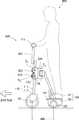
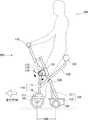
第1の実施例について説明する。図1は、第1の実施例に係る走行装置100の低速走行時における側面概観図であり、図2は、図1の状態における走行装置100を上方から観察した上面概観図である。なお、図2では、図1において点線で示すユーザ900を省いている。 A first embodiment will be described. FIG. 1 is a side view of the
走行装置100は、パーソナルモビリティの一種であり、ユーザが立って搭乗することを想定した電動式の移動用車輌である。走行装置100は、走行方向に対して1つの前輪101と2つの後輪102(右側後輪102a、左側後輪102b)を備える。前輪101は、ユーザ900がハンドル115を操作することで向きが変わり、操舵輪として機能する。右側後輪102aと左側後輪102bは、車軸103で連結されており、不図示のモータと減速機構によって駆動されて、駆動輪として機能する。走行装置100は、3つの車輪によって3点で接地しており、ユーザ900が搭乗していない駐機状態でも自立する、静的安定車輌である。 The
前輪101は、前輪支持部材110により回転可能に支持されている。前輪支持部材110は、前側支柱111とフォーク112を含む。フォーク112は、前側支柱111の一端側に固定されており、前輪101を両側方から挟んで回転自在に軸支している。前側支柱111の他端側には、ハンドル115が前輪101の回転軸方向に延伸するように固定されている。ユーザ900がハンドル115を旋回操作すると、前側支柱111は、その操作力を伝達して前輪101の向きを変える。 The
後輪102は、後輪支持部材120により回転可能に支持されている。後輪支持部材120は、後側支柱121と本体部122を含む。本体部122は、後側支柱121の一端側を固定支持すると共に、車軸103を介して右側後輪102aと左側後輪102bを回転自在に軸支している。本体部122は、上述のモータと減速機構、モータに給電するバッテリ等を収容する筐体の機能も担う。本体部122の上面にはユーザ900が足を置くためのステップ141が設けられている。 The
前輪支持部材110と後輪支持部材120とは、旋回継手131とヒンジ継手132を介して連結されている。旋回継手131は、前輪支持部材110を構成する前側支柱111のうち、ハンドル115が固定された他端寄りの位置に固定されている。さらに、旋回継手131は、ヒンジ継手132に枢設されており、前側支柱111の伸延方向と平行な旋回軸TA周りに、ヒンジ継手132と相対的に回動する。ヒンジ継手132は、後輪支持部材120を構成する後側支柱121のうち、本体部122に支持された一端とは反対側の他端と枢設されており、車軸103の伸延方向と平行なヒンジ軸HA周りに、後側支柱121と相対的に回動する。The front
このような構造により、ユーザ900は、ハンドル115を旋回させると、後輪支持部材120に対して旋回軸TA周りに前輪支持部材110が旋回して前輪101の向きを変えられる。また、ユーザ900は、ハンドル115を走行方向に対して前方へ傾けると、その動作が伝達することにより、前輪支持部材110と後輪支持部材120とがヒンジ軸HA周りに相対的に回転して、前側支柱111と後側支柱121の成す角を小さくできる。前側支柱111と後側支柱121の成す角が小さくなると、前輪101と後輪102のホイールベース(WB)の間隔であるWB長は短くなる。逆に、ユーザ900は、ハンドル115を走行方向に対して後方へ傾けると、前輪支持部材110と後輪支持部材120とがヒンジ軸HA周りに相対的に回転して、前側支柱111と後側支柱121の成す角を大きくできる。前側支柱111と後側支柱121の成す角が大きくなると、WB長は長くなる。すなわち、ユーザ900は、自身の動作を回転力として作用させることにより、WB長を短くしたり長くしたりできる。This structure, the
ヒンジ継手132の近傍には、付勢バネ133が取り付けられている。付勢バネ133は、ヒンジ軸HA周りに、前側支柱111と後側支柱121の成す角を小さくする回転方向へ付勢力を発揮する。付勢バネ133は、例えば、トーションバネである。付勢バネ133の付勢力は、ユーザ900がハンドル115に触れない場合に、前側支柱111と後側支柱121の成す角が構造上の最小角になるように変化させ、一方で、ユーザ900がハンドル115を走行方向に対して後方へ容易に傾けられる程度に設定されている。したがって、ユーザ900は、ハンドル115への加重およびステップ141への加重の少なくともいずれかを変化させることにより、前側支柱111と後側支柱121の成す角を調整でき、ひいてはWB長を調整できる。An
ヒンジ継手132の近傍には、回転角センサ134が取り付けられている。回転角センサ134は、ヒンジ軸HA周りに前側支柱111と後側支柱121の成す角を出力する。回転角センサ134は、例えば、ロータリエンコーダである。回転角センサ134の出力は、後述する制御部へ送信される。A
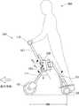
走行装置100は、WB長が短ければ低速で走行し、WB長が長ければ高速で走行する。図1は、WB長が短い低速走行時の様子を示している。図3は、図1と同様の走行装置100の側面概観図であるが、WB長が長い高速走行時の様子を示している。 The traveling
図示するように、前側支柱111と後側支柱121の成す角を、相対的に開く方向を正として、回転角θとする。また、回転角θが取り得る最小値(最小角)をθMIN、最大値(最大角)をθMAXとする。例えばθMIN=10度でありθMAX=80度である。換言すると、回転角θがθMINとθMAXの範囲に収まるように、構造上の規制部材が設けられている。As shown in the figure, the angle formed by the
WB長は、回転角θと一対一に対応し、WB長=f(θ)の関数により換算できる。したがって、回転角θを変化させることによりWB長を調整できる。本実施例における走行装置100は、ユーザ900が回転角θを大きくすると加速し、小さくすると減速する。つまり、回転角θに対して目標速度が対応付けられており、回転角θが変化すると、それに応じた目標速度に到達するように加減速する。別言すれば、回転角θを媒介変数としてWB長と目標速度が対応付けられており、ユーザ900がWB長を調整すると、目標速度がそのWB長に応じて変化する構成となっている。 The WB length has a one-to-one correspondence with the rotation angle θ and can be converted by a function of WB length = f (θ). Therefore, the WB length can be adjusted by changing the rotation angle θ. The traveling
回転角θが小さくなるとWB長が短くなるので、小回りが利く。すなわち、狭い場所でも動き回ることができる。逆に回転角θが大きくなるとWB長が長くなるので、走行安定性、特に直進性が向上する。すなわち、高速で走行しても路面上の段差等による揺動を受けにくい。また、速度とWB長が連動して変化するので、低速なのにWB長が長いような状態になることが無く、その速度で必要最低限な投影面積で移動ができる。すなわち、走行装置100が移動するために必要な路面上の面積が小さく、余分なスペースを必要としない。これは駐機する場合にも特にその効果を発揮する。また、ユーザ900は、ハンドル115を前後に傾ければ、速度とWB長の両方を連動させて変化させることができるので、運転操作としても簡便で容易である。 As the rotation angle θ is reduced, the WB length is shortened, so that a small turn is advantageous. That is, it can move around in a narrow place. On the contrary, when the rotation angle θ is increased, the WB length is increased, so that the running stability, particularly the straight traveling performance is improved. That is, even if the vehicle travels at a high speed, it is difficult to receive a swing due to a step on the road surface. Further, since the speed and the WB length change in conjunction with each other, the WB length does not become long although the speed is low, and the movement can be performed with the minimum necessary projection area at the speed. That is, the area on the road surface required for the traveling
さらに、WB長の調整はユーザ900の動作によって生じる作用力が伝達することによって実現されており、WB長を調整するためのアクチュエータを必要としない。したがって、本実施例における走行装置100は装置全体として軽量化が図られており、例えばユーザ900が走行装置100を容易に電車に持ち込むことができるなど、これまでのパーソナルモビリティにはない利便性を提供できる。 Furthermore, the adjustment of the WB length is realized by transmitting an acting force generated by the operation of the
図4は、走行装置100の制御ブロック図である。制御部200は、例えばCPUであり、本体部122に収容されている。駆動輪ユニット210は、駆動輪である後輪102を駆動するための駆動回路やモータを含み、本体部122に収容されている。制御部200は、駆動輪ユニット210へ駆動信号を送ることにより、後輪102の回転制御を実行する。 FIG. 4 is a control block diagram of the traveling
車速センサ220は、後輪102または車軸103の回転量を監視して、走行装置100の速度を検出する。車速センサ220は、制御部200の要求に応じて、検出結果を速度信号として制御部200へ送信する。回転角センサ134は、上述のように、回転角θを検出する。回転角センサ134は、制御部200の要求に応じて、検出結果を回転角信号として制御部200へ送信する。 The
荷重センサ240は、ステップ141へ加えられる荷重を検出する、例えば圧電フィルムであり、ステップ141に埋め込まれている。荷重センサ240は、制御部200の要求に応じて、検出結果を荷重信号として制御部200へ送信する。 The
メモリ250は、不揮発性の記憶媒体であり、例えばソリッドステートドライブが用いられる。メモリ250は、走行装置100を制御するための制御プログラムの他にも、制御に用いられる様々なパラメータ値、関数、ルックアップテーブル等を記憶している。メモリ250は、回転角θを目標速度に変換する変換テーブル251を記憶している。 The
図5は、回転角θを目標速度に変換する変換テーブル251の一例としての、回転角θと目標速度の関係を示すグラフである。図示するように、目標速度は回転角θの一次関数として表されており、回転角θが大きくなるにつれて、目標速度が大きくなるように設定されている。最小角θMIN(度)のときに目標速度は0であり、最大角θMAX(度)のときに目標速度は最高速度Vm(km/h)である。このように、変換テーブル251は、関数形式であっても良い。FIG. 5 is a graph showing the relationship between the rotation angle θ and the target speed as an example of the conversion table 251 for converting the rotation angle θ into the target speed. As shown in the figure, the target speed is expressed as a linear function of the rotation angle θ, and is set so that the target speed increases as the rotation angle θ increases. The target speed is 0 at the minimum angle θMIN (degrees), and the target speed is the maximum speed Vm (km / h) at the maximum angle θMAX (degrees). Thus, the conversion table 251 may be in a function format.
図6は、回転角θを目標速度に変換する変換テーブル251の他の一例としての、回転角θと目標速度の関係を示すテーブルである。図5の例では、連続的に変化する回転角θに対して連続的に変化する目標速度を対応付けた。図6の例では、連続的に変化する回転角θを複数のグループに区分して、それぞれにひとつの目標速度を対応付ける。 FIG. 6 is a table showing the relationship between the rotation angle θ and the target speed as another example of the conversion table 251 for converting the rotation angle θ into the target speed. In the example of FIG. 5, the continuously changing target speed is associated with the continuously changing rotation angle θ. In the example of FIG. 6, the continuously changing rotation angle θ is divided into a plurality of groups, and one target speed is associated with each group.
図示するように、回転角θが、θMIN以上θ1未満である場合に目標速度0(km/h)を対応付け、θ1以上θ2未満である場合に目標速度5.0(km/h)を対応付け、θ2以上θ3未満である場合に目標速度10.0(km/h)を対応付け、θ3以上θMAX以下である場合に目標速度15.0(km/h)を対応付ける。このような場合の変換テーブル251は、ルックアップテーブル形式を採用することができる。このように目標速度を、ある程度幅を持たせた回転角θの範囲に対応付けると、例えばユーザ900の体の揺れに影響されて小刻みに目標速度が変わるようなことがなくなり、滑らかな速度変化を期待できる。もちろん、範囲の境界にヒステリシスを持たせても良く、加速時と減速時で範囲の境界を異ならせれば、より滑らかな速度変化を期待できる。As illustrated, the rotation angle theta is, theta when it is more than theta less than1MIN associated target speed 0 (km / h), the target speed 5.0 is less than theta1 or θ2 (km / h) in correspondence, and when θ2 or more and less than θ3 , target speed 10.0 (km / h) is associated, and when θ3 or more and θMAX or less, target speed 15.0 (km / h) Associate. The conversion table 251 in such a case can adopt a lookup table format. In this way, when the target speed is associated with the range of the rotation angle θ that has a certain width, the target speed does not change little by little due to the shaking of the body of the
回転角θと目標速度の対応付けは、図5や図6の例に限らず、さまざまな対応付けが可能である。例えば、回転角θの変化量に対する目標速度の変化量を、低速領域においては小さく設定し、高速領域においては大きく設定するといったアレンジも可能である。また、本実施例では、回転角θがWB長と一対一に対応することから、媒介変数である回転角θを目標速度と対応付ける変換テーブル251を採用しているが、本来の趣旨通りに、WB長を目標速度と対応付ける変換テーブルを採用しても良い。この場合は、回転角センサ134から取得される回転角θを上述の関数を用いてWB長に換算してから、変換テーブルを参照すれば良い。 The association between the rotation angle θ and the target speed is not limited to the examples in FIGS. 5 and 6, and various associations are possible. For example, it is possible to arrange such that the change amount of the target speed with respect to the change amount of the rotation angle θ is set small in the low speed region and large in the high speed region. In this embodiment, since the rotation angle θ has a one-to-one correspondence with the WB length, the conversion table 251 that associates the rotation angle θ, which is a parameter, with the target speed is employed, but as originally intended, You may employ | adopt the conversion table which matches WB length with target speed. In this case, the conversion angle may be referred to after converting the rotation angle θ acquired from the
次に、本実施例における、走行処理について説明する。図7は、走行中の処理を示すフロー図である。フローは、電源スイッチがオンにされ、荷重センサ240から荷重ありの信号を受け取った時点、すなわちユーザ900が搭乗した時点から開始する。 Next, the traveling process in the present embodiment will be described. FIG. 7 is a flowchart showing processing during travel. The flow starts when the power switch is turned on and a signal with a load is received from the
制御部200は、ステップS101で、回転角センサ134から回転角信号を取得して現在の回転角θを算出する。そして、ステップS102で、算出した回転角θを、メモリ250から読み出した変換テーブル251に当てはめ、目標速度を設定する。 In step S101, the
制御部200は、目標速度を設定したら、ステップS103へ進み、駆動ユニット210へ対して加減速の駆動信号を送信する。具体的には、まず車速センサ220から速度信号を受け取り、現在の速度を確認する。そして、目標速度が、現在の速度より大きければ加速する駆動信号を駆動ユニット210へ送信し、現在の速度より小さければ減速する駆動信号を駆動ユニット210へ送信する。 After setting the target speed, the
制御部200は、加減速中も回転角θが変化したか、つまり、ユーザ900がハンドル115を前後に傾けたかを監視する(ステップS104)。回転角θが変化したと判断したら、再度ステップS101からやり直す。変化していないと判断したらステップS105へ進む。なお、図6のような変換テーブルを採用している場合は、回転角θがひとつの範囲に留まる間は、変化していないと判断する。 The
制御部200は、ステップS105で、車速センサ220から速度信号を受け取り、目標速度に到達したか否かを判断する。目標速度に到達していないと判断したら、ステップS103へ戻り、加減速を継続する。目標速度に到達したと判断したら、ステップS106へ進む。ステップS106では、目標速度が0であったか否かを確認する。目標速度が0であったなら、ステップS106の時点では走行装置100は停止していることになる。そうでなければ、目標速度により走行中であるので、制御部200は、その速度で走行を維持するように駆動信号を駆動輪ユニット210へ送信する(ステップS107)。 In step S105, the
制御部200は、ステップS107で定速走行している間も、回転角θが変化したか、つまり、ユーザ900がハンドル115を前後に傾けたかを監視する(ステップS108)。回転角θが変化したと判断したら、ステップS101へ戻る。変化していないと判断したら定速走行を続けるべく、ステップS107へ戻る。 The
ステップS106で目標速度が0であったと確認したら、ステップS109へ進み、ユーザ900が降機したかを荷重センサ240から受信する荷重信号から判断する。ユーザ900が降機していない、つまり荷重があると判断したら、走行制御を継続すべくステップS101へ戻る。降機したと判断したら、一連の処理を終了する。 If it is confirmed in step S106 that the target speed is 0, the process proceeds to step S109, and it is determined from the load signal received from the
次に、走行装置100の変形例としての第2の実施例から第8の実施例まで順に説明する。これらの変形例は、走行装置100に対してハードウェアとしての構成がそれぞれ若干異なるが、いずれも搭乗者であるユーザ900の動作により前輪支持部材110と後輪支持部材120の成す角が変化してWB長が調整される点において共通する。また、制御ブロックの構成や処理フローも、特に説明する場合を除いて図4から図7を用いて説明したものと同様である。したがって、以下の説明においては、主にハードウェアとしての相違点について説明する。また、走行装置100と同様の機能を担う要素については、第1の実施例における符番と同じ符番を付して、その説明を省略する。 Next, the second embodiment to the eighth embodiment as modified examples of the traveling
図8は、第2の実施例に係る走行装置510の高速走行時における側面概観図である。第1の実施例に係る走行装置100では、本体部122の上面にユーザ900が両足を置くためのステップ141が設けられていたが、走行装置510は、フォーク112の側面に前側ステップ511を備える。また、本体部122の上面には後側ステップ512を備える。ユーザ900は、左右の足の一方を前側ステップ511に載せ、他方を後側ステップ512に載せる。図8は、ユーザ900が左足を前側ステップ511に載せ、右足を後側ステップ512に載せている様子を示す。逆に、右足を前に左足を後に載せられるように、走行方向に対して、前側ステップ511はフォーク112の両側に設けられており、後側ステップ512も本体部122の上面の両側に設けられている。 FIG. 8 is a schematic side view of the traveling
このように、ユーザ900が左右の足を前後に開いて搭乗するスタイルを採用すると、ユーザ900は、ハンドル115を前後方向に加重するに限らず、開いた足を前後に開いたり閉じたりする動作によっても、前輪支持部材110と後輪支持部材120の成す角を変化させることができる。また、足を前後に開いているので、走行方向におけるユーザ900の重心が、前輪101と後輪102の間に位置する。したがって、搭乗時におけるバランスが安定しやすい。 As described above, when the
また、前輪支持部材110と後輪支持部材120の成す角が小さくなる方向に付勢バネ133が作用しているので、不意に足が開いて速度が増してしまうことがない。さらに、ユーザ900は、足を前後に開く場合に付勢バネ133の付勢力に抗して力を加えることになるので、WB長を伸ばして加速させるインタフェースとして親和性が高い。 Further, since the biasing
なお、フォーク112の側面に設けられた前側ステップ511に限らず、前足から加重を受けて前輪支持部材110に伝達する部材であれば、前足と接触する接触部材は、いかなる形状や構造であっても構わない。例えば前側支柱111に膝当部が設けられており、ユーザ900が当該膝当部に膝を押し当てて前輪支持部材110を前方に押し出す構造であっても良い。同様に、本体部122の上面に設けられた後側ステップ512に限らず、後足から加重を受けて後輪支持部材120に伝達する部材であれば、後足と接触する部材は、いかなる形状や構造であっても構わない。 The contact member that contacts the front foot is not limited to the
図9は、第3の実施例に係る走行装置520の低速走行時における側面概観図である。第1の実施例に係る走行装置100では、ユーザ900がハンドル115を走行方向に対して前方へ傾けるとWB長が短くなり後方へ傾けるとWB長が長くなった。換言すれば、前側支柱111に固定されたハンドル115は、前側支柱111と後側支柱121が相対的に回動するヒンジ軸HAを揺動軸として前後に揺動し、ユーザ900がハンドル115を揺動させると前側支柱111と後側支柱121の成す角が変化する構成であった。第3の実施例に係る走行装置520では、ユーザ900がハンドル115を走行方向に対して前方へ傾けるとWB長が長くなり後方へ傾けるとWB長が短くなる。具体的には、走行装置520は、ユーザ900がハンドル115を揺動軸SAに対して一方向へ揺動させた場合に、前輪支持部材110がヒンジ軸HAに対して逆方向へ回転される反転機構を備える。FIG. 9 is a schematic side view of the traveling
反転機構は、ハンドル115を固定支持するハンドル支柱521の一端に固定されたハンドル側ギア522と、ハンドル側ギア522と噛み合い、前側支柱111のうちフォーク112を支持する一端とは反対側の他端に固定された前輪側ギア523とを含む。また、反転機構は、ハンドル側ギア522と前輪側ギア523とが噛み合って回動できるようにそれぞれを軸支する旋回継手524を含む。旋回継手524は、ハンドル支柱521が前輪101の車軸と平行な揺動軸SA周りに揺動できるようにハンドル側ギア522を軸支し、前側支柱111が前輪101の車軸と平行なヒンジ軸HA周りに回動できるように前輪側ギア523を軸支する。The reversing mechanism includes a handle-
さらに、旋回継手524は、後輪支持部材120を構成する後側支柱121のうち、本体部122に支持された一端とは反対側の他端に枢設されており、鉛直成分を含むように設定された旋回軸TA周りに、後側支柱121と相対的に回動する。ハンドル側ギア522と前輪側ギア523は、例えば幅広で剛性の高い平歯車であって互いに噛合しており、ユーザ900がハンドル115を旋回軸TA周りに旋回させると、その作用力が前輪支持部材110に伝達され、前輪101の向きを変えられる。Further, the swivel joint 524 is pivotally provided at the other end of the
なお、付勢バネ133と回転角センサ134は、ヒンジ軸HAの両側に設置されている。付勢バネ133は、前側支柱111と後側支柱121の成す角が小さくなる方向に付勢し、回転角センサ134は、前側支柱111と後側支柱121の成す角を検出する。The biasing
図10は、第3の実施例に係る走行装置520の高速走行時における側面概観図である。図9の状態からユーザ900がハンドル115を走行方向に対して前側に傾けると、ハンドル支柱521は揺動軸SA周りに揺動し、前側支柱111はヒンジ軸HA周りを反対方向へ回動する。すると、図10で示すように、前輪101が走行方向へ突き出され、前側支柱111と後側支柱121の成す角θが大きくなり、WB長が長くなる。WB長が長くなると、上述のように目標速度が大きく設定され、走行装置520はより高速で走行する。FIG. 10 is a schematic side view of the traveling
このように、ハンドル115が徐々に前方に傾くように構成すると、ユーザ900は、高速走行になるほど前傾姿勢となるが、WB長も長くなるので、その重心は走行方向において前輪101と後輪102の中間付近に常に位置することになる。これにより、ユーザ900は、低速走行から高速走行にわたって安定的にバランスを保って運転することができる。 As described above, when the
なお、走行装置520では反転機構としてハンドル側ギア522と前輪側ギア523とが噛み合って互いに逆向きに回動する機構を利用したが、他にも様々な機構を採用し得る。ユーザ900がハンドル115を揺動軸SAに対して一方向へ揺動させた場合に、前輪支持部材110がヒンジ軸HAに対して逆方向へ回転されるものであれば、いずれの反転機構であっても構わない。例えば、ハンドル支柱521と前側支柱111を、四辺リンク機構で接続しても良い。In the traveling
また、走行装置520においては、ハンドル115を前後に傾けると旋回軸TAも変化するが、例えばハンドル支柱521の中間部にユニバーサルジョイントを設ければ、走行速度によらずハンドル115の旋回方向を一定に保つことができる。あるいは、後側支柱121に旋回軸TAが鉛直を保つ機構を設けても良い。Further, in the traveling
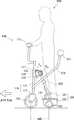
図11は、第4の実施例に係る走行装置530の低速走行時における側面概観図であり、図12は、図11の状態における走行装置530を上方から観察した上面概観図である。なお、図12では、図11において点線で示すユーザ900を省いている。走行装置530は、押圧バー531、押下支柱532、作用ピン533を備える点で第1の実施例に係る走行装置100と異なる。 FIG. 11 is a schematic side view of the traveling
押下支柱532は、二股に分かれた先端側において前側支柱111を両側から挟むように前側支柱111に固定して連結されている連結部材である。押下支柱532は、上面から見た場合に二股部分が後側支柱121と離間して回り込むように配置されて後端側でY字状に一本化されており、側面から見た場合に前側支柱111に固定された先端から後端へ向かって斜め上方へ延伸している。押下支柱532の後端には、走行面に平行で進行方向に直交する向きに棒状の押圧バー531が取り付けられている。 The
押下支柱532の二股部分が後側支柱121と離間して配置されているので、前輪支持部材110を旋回軸TA周りに一定の範囲で旋回しても、後側支柱121と押下支柱532とが干渉することはない。また、押下支柱532の後端側が一本化されているので、ユーザ900は、これを跨いでステップ141に搭乗することができる。Since the bifurcated portion of the
作用ピン533は、後側支柱121の中間付近から両側方へ突出するように設けられている。作用ピン533は、押下支柱532の二股部分において、その底面と接触している。 The
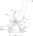
図13は、第4の実施例に係る走行装置530の高速走行時における側面概観図である。図12の状態から、ユーザ900が、臀部や背部など後背部で押圧バー531を押下げると、その押下力が前側支柱111に伝達され前輪101を前方へ押し出す。また、押下支柱532が作用ピン533に接触して相対的に摺動しつつ作用ピン533が押下げられ、後側支柱121が後輪102を相対的に後方へ押し出す。このような作用により成す角θが大きくなり、WB長が長くなる。WB長が長くなると、上述のように目標速度が大きく設定され、走行装置530はより高速で走行する。 FIG. 13 is a side view of the traveling
すなわち、ユーザ900は、後背部で押圧バー531を押圧する押圧力を調整すると、WB長を変化させることができ、ひいては走行速度を調節することができる。このような構成によれば、ユーザ900は、直感的な操作感で走行装置530を運転操作することができる。なお、押圧バー531は、後背部からの押圧力を受けるものであれば、棒状の形状に限らない。臀部や背部に沿う曲面形状を採用しても良い。 That is, the
図14は、第5の実施例に係る走行装置540の高速走行時における側面概観図である。走行装置540は、第4の実施例に係る走行装置530に対して、第2の実施例に係る走行装置510の前側ステップ511を設置したものである。走行装置540では、ユーザ900は、両足共に前側ステップ511に載せる。そして、後背部で押圧バー531を押下げることにより後輪102を相対的に後方へ押し出す。このような構成においても、ユーザ900は、直感的な操作感で走行装置530を運転操作することができる。 FIG. 14 is a schematic side view of the traveling
図15は、第6の実施例に係る走行装置550の高速走行時における側面概観図である。走行装置550は、第2の実施例に係る走行装置510に対して、腰掛部551を設けたものである。腰掛部551は、一端が本体部122に固定された腰掛支柱552の他端に固定されている。ユーザ900は、両足を共に前側ステップ511に載せ、腰掛部551に腰掛ける。ユーザ900は、WB長を長くしたい場合には、足を伸ばして前側ステップ511に加重し、前輪101を前方へ押し出す。このようにしてWB長が長くなると、上述のように目標速度が大きく設定され、走行装置550はより高速で走行する。なお、ユーザ900は、前側ステップ511への加重を弱めれば、付勢バネ133の作用により前輪101が引き戻され、WB長を短くすることができる。このような構成によれば、ユーザ900は、腰掛けて運転操作ができるので、長時間の搭乗に対して有利である。 FIG. 15 is a schematic side view of the traveling
図16は、第7の実施例に係る走行装置560の低速走行時における側面概観図である。第5の実施例に係る走行装置540では、前輪支持部材110に押下支柱532を連結して押圧バー531を設けた。また、ハンドル115は、前輪支持部材110と一体的に構成されている。すなわち、ハンドル115、前輪支持部材110、押圧バー531が一体的であり、これらが後輪支持部材120に対してヒンジ軸HA周りに相対的に回動する構成であった。走行装置560は、前輪支持部材110と押圧バー531が一体的であり、これらが一体的に構成された後輪支持部材120とハンドル115に対してヒンジ軸HA周りに相対的に回動する構成である。FIG. 16 is a schematic side view of the traveling
ユーザ900は、前側ステップ511に両足を載せてバランスを取る。そして、後背部で押圧バー531を押圧して押下支柱532を押下げる。すると、押下支柱532が作用ピン533に接触して相対的に摺動しつつ作用ピン533が押下げられ、後側支柱121が後輪102を相対的に後方へ押し出す。このような作用により成す角θが大きくなり、WB長が長くなる。WB長が長くなると、上述のように目標速度が大きく設定され、走行装置530はより高速で走行する。 The
このように、前輪支持部材110に連結されて、ユーザ900の後背部側から加重を受ける押圧バー531および押下支柱532と、後輪支持部材120に連結されたハンドル115とがヒンジ軸HAで接続された走行装置560は、第5の実施例に係る走行装置540と同様に、簡単な部品構成で実現される。In this way, the
なお、走行装置560では、ハンドル115が旋回されると後輪支持部材120が旋回軸TA周りに旋回し、後輪102の向きが変わる。旋回操作をより軽い力で行えるようにしたい場合には、後輪102を従動輪にして、前輪101を駆動輪にすれば良い。In the
図17は、第8の実施例に係る走行装置570の低速走行時における側面概観図である。これまで説明した各実施例における走行装置は、前輪支持部材110と後輪支持部材120とがヒンジ軸を中心として相対的に回動する構成を採用した。走行装置570は、ヒンジ軸ではなく、接続部を板バネ571とワイヤ572で構成する。 FIG. 17 is a schematic side view of the traveling
旋回継手576は、後輪支持部材120を構成する後側支柱121のうち、本体部122に支持された一端とは反対側の他端に枢設されており、鉛直成分を含むように設定された旋回軸TA周りに、後側支柱121と相対的に回動する。前輪支持部材110を構成する前側支柱111の上部近傍には取付部材573が固定されている。旋回継手576と取付部材573は走行方向に対向し、旋回継手576と取付部材573の両側方に板バネ571とワイヤ572がそれぞれ懸架されて固定されている。The swivel joint 576 is pivoted to the other end of the
板バネ571は、図示するように、側方から見た場合に上方向に開口したU字状に曲げられて固定されている。その結果、板バネ571は、前側支柱111と後側支柱121の成す角が小さくなる方向に付勢力が作用する。一方でワイヤ572が板バネ571の付勢力で伸張され、前側支柱111と後側支柱121の成す角が一定角よりも小さくなることを防いでいる。また、板バネ571は、前輪101の車軸方向には高い剛性を有し、ハンドル115が旋回された場合には、旋回軸TA周りに旋回継手576を回動させることができる。As shown in the figure, the
WB長は、本体部122に設けられた距離センサ574により検出する。距離センサ574は、例えばレーザー距離計であり、フォーク112に設けられたコーナーキューブ575で再起反射した反射光を受光してWB長を検出する。 The WB length is detected by a
図18は、第8の実施例に係る走行装置570の高速走行時における側面概観図である。図17の状態からユーザ900が板バネ571の付勢力に抗してハンドル115を後方に傾斜させると、前輪101が前方に押し出されてWB長が長くなる。このとき、ワイヤ572は、旋回継手576と取付部材573の間で弛む。WB長が長くなると、上述のように目標速度が大きく設定され、走行装置530はより高速で走行する。 FIG. 18 is a schematic side view of the traveling
このように構成された走行装置570は、前輪支持部材110と後輪支持部材120の成す角を調整する回転部の機構としてヒンジに限らない設計を可能とする。なお、回転部は、一端が前輪支持部材110に、他端が後輪支持部材120に接続され、前輪支持部材110と後輪支持部材120の成す角を小さくする方向へ付勢するものであれば、板バネ571に限らず、他の弾性部材であっても構わない。また、このような回転部の機構は、上述の各実施例における走行装置に適用しても良い。 The traveling
図19は、第8の実施例の変形例に係る走行装置の側面概観図であって、図17に対応する図である。本変形例では、取付部材573を後側支柱121のうち、本体部122に支持された一端とは反対側の他端に設けている。また、旋回継手576を前側支柱111に枢設させている。本変形例でも同様に、旋回継手576と取付部材573は走行方向に対向し、旋回継手576と取付部材573の両側方に板バネ571とワイヤ572がそれぞれ懸架されて固定されている。 FIG. 19 is a schematic side view of a traveling device according to a modification of the eighth embodiment, corresponding to FIG. In this modification, the
旋回継手576は、前側支柱111に対して、前側支柱111の伸延方向と平行な旋回軸TA周りに相対的に回動する。このように旋回軸を形成すると、旋回時に板バネ571の旋回を伴わず、また、旋回軸TAもユーザ900が操作するハンドル115の旋回軸と平行になるので、ユーザ900は、軽いハンドル操作で旋回を行うことができる。Pivot joint 576, with respect to the
また、本変形例は、WB長を距離センサにより直接的に検出するのではなく、WB長に連動するパラメータとして、後側支柱121の鉛直方向に対する傾斜角φを検出する角度センサ577を採用する。角度センサ577は、例えば重力センサである。傾斜角φは、上述の回転角θと同様に、WB長と一対一に対応するので、傾斜角φを検出することにより、WB長に基づく速度制御を実行することができる。なお、角度センサ577を前側支柱111に設置して、前側支柱111の傾斜角を検出するように構成しても良い。 In addition, the present modification employs an
以上各実施例を説明したが、前輪、後輪は、車輪でなくても良く、球状輪、クローラなどの接地要素であっても構わない。また、駆動輪を駆動する動力源はモータに限らず、ガソリンエンジンなどであっても構わない。また、上記の各実施例では、WB長に連動する成す角θに目標速度が一対一に対応付けられる制御例を説明したが、WB長に連動するパラメータに基づいて駆動を制御するものであれば、他の様々な制御も可能となる。例えば、WB長に連動するパラメータに最高速度制限値を対応付け、その制限値までの範囲であればユーザはアクセルスロットルなどによって加減速を調整できるように構成しても良い。 Although the embodiments have been described above, the front wheels and the rear wheels may not be wheels, and may be grounding elements such as spherical wheels and crawlers. The power source for driving the drive wheels is not limited to a motor, and may be a gasoline engine or the like. In each of the above embodiments, the control example in which the target speed is associated with the angle θ formed in conjunction with the WB length on a one-to-one basis has been described. However, the drive may be controlled based on the parameter associated with the WB length. In other words, various other controls are possible. For example, a maximum speed limit value may be associated with a parameter linked to the WB length so that the user can adjust acceleration / deceleration by an accelerator throttle or the like within the range up to the limit value.
100、510、520、530、540、550、560、570 走行装置、101 前輪、102 後輪、103 車軸、110 前輪支持部材、111 前側支柱、112 フォーク、115 ハンドル、120 後輪支持部材、121 後側支柱、122 本体部、131 旋回継手、132 ヒンジ継手、133 付勢バネ、134 回転角センサ、141 ステップ、200 制御部、210 駆動輪ユニット、220 車速センサ、240 荷重センサ、250 メモリ、251 変換テーブル、511 前側ステップ、512 後側ステップ、521 ハンドル支柱、522 ハンドル側ギア、523 前輪側ギア、524 旋回継手、531 押圧バー、532 押下支柱、533 作用ピン、551、561 腰掛部、552 腰掛支柱、571 板バネ、572 ワイヤ、573 取付部材、574 距離センサ、575 コーナーキューブ、576 旋回継手、577 角度センサ、900 ユーザ100, 510, 520, 530, 540, 550, 560, 570 Traveling device, 101 Front wheel, 102 Rear wheel, 103 Axle, 110 Front wheel support member, 111 Front strut, 112 Fork, 115 Handle, 120 Rear wheel support member, 121 Rear strut, 122 body, 131 swivel joint, 132 hinge joint, 133 bias spring, 134 rotation angle sensor, 141 step, 200 control unit, 210 drive wheel unit, 220 vehicle speed sensor, 240 load sensor, 250 memory, 251 Conversion table, 511 Front side step, 512 Rear side step, 521 Handle column, 522 Handle side gear, 523 Front wheel side gear, 524 Swing joint, 531 Press bar, 532 Press column, 533 Working pin, 551, 561 Seat part, 552 Seat Prop, 5 1
Claims (11)
Translated fromJapanese前記前輪を回転可能に支持する前輪支持部材と、
前記後輪を回転可能に支持する後輪支持部材と、
前記前輪および前記後輪の少なくともいずれかを駆動する駆動部と、
前記前輪支持部材と前記後輪支持部材を相対的に回転させる回転部を含み、前記ユーザの動作が伝達することにより前記前輪支持部材と前記後輪支持部材の成す角が変化して、前記前輪と前記後輪のホイールベース長が調整される調整機構と、
前記ホイールベース長に連動するパラメータに基づいて前記駆動部を制御する制御部と
を備える走行装置。A traveling device that has at least a front wheel and a rear wheel with respect to the traveling direction and that the user rides and travels,
A front wheel support member for rotatably supporting the front wheel;
A rear wheel support member for rotatably supporting the rear wheel;
A drive unit for driving at least one of the front wheel and the rear wheel;
A rotation unit that relatively rotates the front wheel support member and the rear wheel support member, and an angle formed by the front wheel support member and the rear wheel support member is changed by transmission of an operation of the user; And an adjustment mechanism for adjusting the wheel base length of the rear wheel,
A travel device comprising: a control unit that controls the drive unit based on a parameter that is linked to the wheelbase length.
前記動作として前記ユーザの他方の足から加重を受けて前記後輪支持部材に伝達する後側接触部と
を備える請求項1または2に記載の走行装置。A front contact portion that receives a load from one foot of the user as the operation and transmits it to the front wheel support member;
The traveling device according to claim 1, further comprising a rear contact portion that receives a load from the other foot of the user as the operation and transmits the weight to the rear wheel support member.
前記調整機構は、前記ユーザが前記ハンドル部を前記揺動軸周りに揺動させる動作により前記前輪支持部材と前記後輪支持部材の成す角が変化する請求項1または2に記載の走行装置。The front wheel is turned in the turning direction, and has a handle portion that can swing around a swing axis parallel to the rotation axis of the rotating portion,
3. The travel device according to claim 1, wherein the adjustment mechanism changes an angle formed by the front wheel support member and the rear wheel support member by an operation in which the user swings the handle portion around the swing shaft.
前記前輪支持部材に連結され、前記動作として前記ユーザの足から加重を受けて前記前輪支持部材を押し出す押出部と
を備える請求項1または2に記載の走行装置。A stool connected to the rear wheel support member and seated by the user;
The travel device according to claim 1, further comprising: an extrusion unit that is connected to the front wheel support member and that receives the weight from the user's foot as the operation and pushes out the front wheel support member.
前記後輪支持部材に連結され、前記ユーザが把持するハンドル部と
を備える請求項1または2に記載の走行装置。A connecting portion connected to the front wheel support member and receiving a load from the back side of the user;
The traveling device according to claim 1, further comprising: a handle portion coupled to the rear wheel support member and gripped by the user.
前記調整機構は、前記前輪支持部材と前記後輪支持部材の成す角を小さくする方向へ付勢する付勢部材を有する請求項1から9のいずれか1項に記載の走行装置。The rotating part is a hinge;
The travel device according to any one of claims 1 to 9, wherein the adjustment mechanism includes a biasing member that biases the angle formed by the front wheel support member and the rear wheel support member in a direction that reduces the angle.
Priority Applications (3)
| Application Number | Priority Date | Filing Date | Title |
|---|---|---|---|
| JP2016158717AJP6380485B2 (en) | 2016-08-12 | 2016-08-12 | Traveling device |
| US15/632,489US10640166B2 (en) | 2016-08-12 | 2017-06-26 | Traveling apparatus |
| CN201710685554.3ACN107719542B (en) | 2016-08-12 | 2017-08-11 | travel device |
Applications Claiming Priority (1)
| Application Number | Priority Date | Filing Date | Title |
|---|---|---|---|
| JP2016158717AJP6380485B2 (en) | 2016-08-12 | 2016-08-12 | Traveling device |
Publications (2)
| Publication Number | Publication Date |
|---|---|
| JP2018024386A JP2018024386A (en) | 2018-02-15 |
| JP6380485B2true JP6380485B2 (en) | 2018-08-29 |
Family
ID=61160877
Family Applications (1)
| Application Number | Title | Priority Date | Filing Date |
|---|---|---|---|
| JP2016158717AActiveJP6380485B2 (en) | 2016-08-12 | 2016-08-12 | Traveling device |
Country Status (3)
| Country | Link |
|---|---|
| US (1) | US10640166B2 (en) |
| JP (1) | JP6380485B2 (en) |
| CN (1) | CN107719542B (en) |
Cited By (1)
| Publication number | Priority date | Publication date | Assignee | Title |
|---|---|---|---|---|
| JP2018039376A (en)* | 2016-09-07 | 2018-03-15 | トヨタ自動車株式会社 | Traveling device |
Families Citing this family (13)
| Publication number | Priority date | Publication date | Assignee | Title |
|---|---|---|---|---|
| CN109070962B (en)* | 2016-03-22 | 2021-07-23 | 福特全球技术公司 | Motor-driven transport scooter |
| JP6561945B2 (en)* | 2016-08-26 | 2019-08-21 | トヨタ自動車株式会社 | Traveling device |
| JP6561944B2 (en)* | 2016-08-26 | 2019-08-21 | トヨタ自動車株式会社 | Traveling device |
| JP6561946B2 (en)* | 2016-08-31 | 2019-08-21 | トヨタ自動車株式会社 | Traveling device |
| JP6493341B2 (en)* | 2016-09-07 | 2019-04-03 | トヨタ自動車株式会社 | Traveling device |
| KR102299340B1 (en)* | 2017-06-09 | 2021-09-08 | 현대자동차주식회사 | Driving mode changeable small mobility |
| USD826087S1 (en)* | 2017-09-04 | 2018-08-21 | Toyota Jidosha Kabushiki Kaisha | Personal transportation vehicle |
| DE102018000114B4 (en)* | 2018-01-10 | 2021-01-28 | Andreas ten Haaft | Vehicle multi-lane and tiltable, with push and ride properties |
| IT201800010256A1 (en)* | 2018-11-13 | 2020-05-13 | Trygana Srl | TRANSFORMABLE VEHICLE ON WHEELS FOR INDIVIDUAL TRANSPORT |
| DE102019006930B3 (en) | 2019-10-02 | 2020-12-31 | Ahmad Omari | Foldable stand-alone scooter |
| US12179878B2 (en)* | 2019-10-21 | 2024-12-31 | Benjamin F. Bailar | Kick scooter performance enhancement |
| US11530011B2 (en)* | 2019-10-21 | 2022-12-20 | Benjamin F. Bailar | Kick scooter performance enhancement |
| US11827308B2 (en)* | 2021-08-31 | 2023-11-28 | Honda Motor Co., Ltd. | Three wheeled electric cargo transporter |
Family Cites Families (33)
| Publication number | Priority date | Publication date | Assignee | Title |
|---|---|---|---|---|
| JPS54105195U (en)* | 1978-01-10 | 1979-07-24 | ||
| US4613151A (en)* | 1984-02-16 | 1986-09-23 | Kielczewski William J | High/low extension-lift power wheelchair |
| GB8515992D0 (en)* | 1985-06-25 | 1985-07-31 | Hester R | Wheelchair |
| JPH01106717A (en)* | 1987-10-20 | 1989-04-24 | Daihatsu Motor Co Ltd | Wheel base variable type rear suspension |
| DE19733033A1 (en)* | 1997-07-31 | 1999-02-18 | Daimler Benz Ag | Single-seat motor vehicle |
| US7900725B2 (en)* | 2002-06-11 | 2011-03-08 | Segway Inc. | Vehicle control by pitch modulation |
| USD483821S1 (en)* | 2002-12-18 | 2003-12-16 | Lien-Chuan Yang | Exercise bike with three wheels |
| JP4333398B2 (en)* | 2004-02-17 | 2009-09-16 | トヨタ車体株式会社 | Wheelbase variable vehicle |
| US7182166B2 (en)* | 2004-03-23 | 2007-02-27 | Deka Products Limited Partnership | Footrest tuck mechanism |
| CA2578196C (en)* | 2004-10-08 | 2014-04-01 | Segway Inc. | Vehicle control by pitch modulation |
| JP4650327B2 (en)* | 2005-04-14 | 2011-03-16 | トヨタ自動車株式会社 | Coaxial motorcycle |
| NZ539543A (en)* | 2005-04-20 | 2008-02-29 | Graham John Mahy | Vehicle with adjustable track width and wheelbase |
| JP4534944B2 (en)* | 2005-10-07 | 2010-09-01 | トヨタ自動車株式会社 | vehicle |
| WO2008150448A1 (en)* | 2007-05-31 | 2008-12-11 | Twill Tech., Inc. | Dynamically balanced in-line wheel vehicle |
| USD586265S1 (en)* | 2007-09-14 | 2009-02-10 | U2 Industry Design Co., Ltd. | Electrical bicycle |
| JP2010167809A (en) | 2009-01-20 | 2010-08-05 | Aisin Seiki Co Ltd | Vehicle and attitude control system |
| WO2010146669A1 (en) | 2009-06-17 | 2010-12-23 | トヨタ自動車株式会社 | Driving assistance device |
| US20120012413A1 (en)* | 2010-07-16 | 2012-01-19 | Cycling & Health Tech Industry R & D Center | Light-duty vehicle with adjustable wheelbase |
| JP2012076671A (en)* | 2010-10-05 | 2012-04-19 | Aisin Seiki Co Ltd | Riding vehicle |
| USD650724S1 (en)* | 2010-10-14 | 2011-12-20 | Chung Chi Chiang | Electric bicycle |
| AU2012203514B2 (en)* | 2011-07-11 | 2014-07-17 | Honda Motor Co., Ltd. | Saddle type vehicle |
| AT511702B1 (en)* | 2011-12-22 | 2013-02-15 | Design & Engineering Company | SCOOTER |
| US8894088B2 (en)* | 2013-01-23 | 2014-11-25 | Massachusetts Institute Of Technology | Methods and apparatus for folding vehicle chassis |
| JP6003712B2 (en)* | 2013-02-19 | 2016-10-05 | トヨタ自動車株式会社 | Small mobile body with caster type rear wheels |
| KR101527487B1 (en)* | 2013-08-27 | 2015-06-09 | 주식회사 만도 | Eletric bicycle and control method thereof |
| CN105722752B (en)* | 2013-09-10 | 2019-01-22 | 城市626有限责任公司 | Folding electric vehicle |
| JP6510240B2 (en)* | 2015-01-13 | 2019-05-08 | 豊田鉄工株式会社 | Folding vehicle |
| USD774979S1 (en)* | 2015-05-28 | 2016-12-27 | Urban626, Llc | Motorized scooter |
| WO2016196510A1 (en)* | 2015-05-29 | 2016-12-08 | Urban626, Llc | Foldable electric vehicle |
| JP6805471B2 (en)* | 2016-02-10 | 2020-12-23 | 豊田鉄工株式会社 | Small electric vehicle |
| US9889872B2 (en)* | 2016-03-28 | 2018-02-13 | Ignio LLC | Multi-function mobility device |
| JP6418202B2 (en) | 2016-07-08 | 2018-11-07 | トヨタ自動車株式会社 | Traveling device |
| WO2018017898A1 (en)* | 2016-07-20 | 2018-01-25 | Urban626, Llc | Convertible scooter |
- 2016
- 2016-08-12JPJP2016158717Apatent/JP6380485B2/enactiveActive
- 2017
- 2017-06-26USUS15/632,489patent/US10640166B2/enactiveActive
- 2017-08-11CNCN201710685554.3Apatent/CN107719542B/enactiveActive
Cited By (1)
| Publication number | Priority date | Publication date | Assignee | Title |
|---|---|---|---|---|
| JP2018039376A (en)* | 2016-09-07 | 2018-03-15 | トヨタ自動車株式会社 | Traveling device |
Also Published As
| Publication number | Publication date |
|---|---|
| US20180043958A1 (en) | 2018-02-15 |
| JP2018024386A (en) | 2018-02-15 |
| CN107719542A (en) | 2018-02-23 |
| US10640166B2 (en) | 2020-05-05 |
| CN107719542B (en) | 2019-06-11 |
Similar Documents
| Publication | Publication Date | Title |
|---|---|---|
| JP6380485B2 (en) | Traveling device | |
| AU771532B2 (en) | Vehicle stabilizing system having pivotal support | |
| JP6170091B2 (en) | Apparatus and method for controlling a dynamic self-balancing vehicle | |
| JP5034948B2 (en) | vehicle | |
| JP6153049B1 (en) | Three-wheeled vehicle | |
| JP2021176754A (en) | vehicle | |
| JP6925923B2 (en) | Electric vehicle | |
| JP2013233895A (en) | Vehicle | |
| JP6575470B2 (en) | Traveling device | |
| JP2011046294A (en) | Vehicle | |
| JP6565831B2 (en) | Traveling device | |
| JP7420699B2 (en) | vehicle | |
| JP6669002B2 (en) | Traveling device | |
| JP6497368B2 (en) | Traveling device | |
| JP2020082997A (en) | Travel vehicle | |
| JP7623002B2 (en) | Electric scooter | |
| JP3541587B2 (en) | Rear wheel suspension for electric wheelchair | |
| JP7546378B2 (en) | Mobile | |
| JP5163895B2 (en) | Traveling vehicle | |
| JP2006103553A (en) | Compact electric vehicle | |
| JP2017178186A (en) | vehicle | |
| JP6699443B2 (en) | Traveling device | |
| JP2560511Y2 (en) | Car seat | |
| JP2013095180A (en) | Coaxial motorcycle | |
| JPH04329952A (en) | Electric wheel chair |
Legal Events
| Date | Code | Title | Description |
|---|---|---|---|
| A977 | Report on retrieval | Free format text:JAPANESE INTERMEDIATE CODE: A971007 Effective date:20180518 | |
| TRDD | Decision of grant or rejection written | ||
| A01 | Written decision to grant a patent or to grant a registration (utility model) | Free format text:JAPANESE INTERMEDIATE CODE: A01 Effective date:20180703 | |
| A61 | First payment of annual fees (during grant procedure) | Free format text:JAPANESE INTERMEDIATE CODE: A61 Effective date:20180716 | |
| R151 | Written notification of patent or utility model registration | Ref document number:6380485 Country of ref document:JP Free format text:JAPANESE INTERMEDIATE CODE: R151 |