JP6378199B2 - Inline adapter for respiratory therapy equipment - Google Patents
Inline adapter for respiratory therapy equipmentDownload PDFInfo
- Publication number
- JP6378199B2 JP6378199B2JP2015548835AJP2015548835AJP6378199B2JP 6378199 B2JP6378199 B2JP 6378199B2JP 2015548835 AJP2015548835 AJP 2015548835AJP 2015548835 AJP2015548835 AJP 2015548835AJP 6378199 B2JP6378199 B2JP 6378199B2
- Authority
- JP
- Japan
- Prior art keywords
- electrical
- tube assembly
- port
- housing
- adapter
- Prior art date
- Legal status (The legal status is an assumption and is not a legal conclusion. Google has not performed a legal analysis and makes no representation as to the accuracy of the status listed.)
- Active
Links
Images


Classifications
- A—HUMAN NECESSITIES
- A61—MEDICAL OR VETERINARY SCIENCE; HYGIENE
- A61M—DEVICES FOR INTRODUCING MEDIA INTO, OR ONTO, THE BODY; DEVICES FOR TRANSDUCING BODY MEDIA OR FOR TAKING MEDIA FROM THE BODY; DEVICES FOR PRODUCING OR ENDING SLEEP OR STUPOR
- A61M16/00—Devices for influencing the respiratory system of patients by gas treatment, e.g. ventilators; Tracheal tubes
- A61M16/08—Bellows; Connecting tubes ; Water traps; Patient circuits
- A61M16/0816—Joints or connectors
- A—HUMAN NECESSITIES
- A61—MEDICAL OR VETERINARY SCIENCE; HYGIENE
- A61M—DEVICES FOR INTRODUCING MEDIA INTO, OR ONTO, THE BODY; DEVICES FOR TRANSDUCING BODY MEDIA OR FOR TAKING MEDIA FROM THE BODY; DEVICES FOR PRODUCING OR ENDING SLEEP OR STUPOR
- A61M16/00—Devices for influencing the respiratory system of patients by gas treatment, e.g. ventilators; Tracheal tubes
- A61M16/0057—Pumps therefor
- A—HUMAN NECESSITIES
- A61—MEDICAL OR VETERINARY SCIENCE; HYGIENE
- A61M—DEVICES FOR INTRODUCING MEDIA INTO, OR ONTO, THE BODY; DEVICES FOR TRANSDUCING BODY MEDIA OR FOR TAKING MEDIA FROM THE BODY; DEVICES FOR PRODUCING OR ENDING SLEEP OR STUPOR
- A61M15/00—Inhalators
- A61M15/08—Inhaling devices inserted into the nose
- A—HUMAN NECESSITIES
- A61—MEDICAL OR VETERINARY SCIENCE; HYGIENE
- A61M—DEVICES FOR INTRODUCING MEDIA INTO, OR ONTO, THE BODY; DEVICES FOR TRANSDUCING BODY MEDIA OR FOR TAKING MEDIA FROM THE BODY; DEVICES FOR PRODUCING OR ENDING SLEEP OR STUPOR
- A61M16/00—Devices for influencing the respiratory system of patients by gas treatment, e.g. ventilators; Tracheal tubes
- A61M16/06—Respiratory or anaesthetic masks
- A61M16/0666—Nasal cannulas or tubing
- A—HUMAN NECESSITIES
- A61—MEDICAL OR VETERINARY SCIENCE; HYGIENE
- A61M—DEVICES FOR INTRODUCING MEDIA INTO, OR ONTO, THE BODY; DEVICES FOR TRANSDUCING BODY MEDIA OR FOR TAKING MEDIA FROM THE BODY; DEVICES FOR PRODUCING OR ENDING SLEEP OR STUPOR
- A61M16/00—Devices for influencing the respiratory system of patients by gas treatment, e.g. ventilators; Tracheal tubes
- A61M16/08—Bellows; Connecting tubes ; Water traps; Patient circuits
- A61M16/0816—Joints or connectors
- A61M16/0833—T- or Y-type connectors, e.g. Y-piece
- A—HUMAN NECESSITIES
- A61—MEDICAL OR VETERINARY SCIENCE; HYGIENE
- A61M—DEVICES FOR INTRODUCING MEDIA INTO, OR ONTO, THE BODY; DEVICES FOR TRANSDUCING BODY MEDIA OR FOR TAKING MEDIA FROM THE BODY; DEVICES FOR PRODUCING OR ENDING SLEEP OR STUPOR
- A61M16/00—Devices for influencing the respiratory system of patients by gas treatment, e.g. ventilators; Tracheal tubes
- A61M16/08—Bellows; Connecting tubes ; Water traps; Patient circuits
- A61M16/0875—Connecting tubes
- A—HUMAN NECESSITIES
- A61—MEDICAL OR VETERINARY SCIENCE; HYGIENE
- A61M—DEVICES FOR INTRODUCING MEDIA INTO, OR ONTO, THE BODY; DEVICES FOR TRANSDUCING BODY MEDIA OR FOR TAKING MEDIA FROM THE BODY; DEVICES FOR PRODUCING OR ENDING SLEEP OR STUPOR
- A61M16/00—Devices for influencing the respiratory system of patients by gas treatment, e.g. ventilators; Tracheal tubes
- A61M16/10—Preparation of respiratory gases or vapours
- A61M16/1075—Preparation of respiratory gases or vapours by influencing the temperature
- A61M16/1095—Preparation of respiratory gases or vapours by influencing the temperature in the connecting tubes
- A—HUMAN NECESSITIES
- A61—MEDICAL OR VETERINARY SCIENCE; HYGIENE
- A61M—DEVICES FOR INTRODUCING MEDIA INTO, OR ONTO, THE BODY; DEVICES FOR TRANSDUCING BODY MEDIA OR FOR TAKING MEDIA FROM THE BODY; DEVICES FOR PRODUCING OR ENDING SLEEP OR STUPOR
- A61M16/00—Devices for influencing the respiratory system of patients by gas treatment, e.g. ventilators; Tracheal tubes
- A61M16/0057—Pumps therefor
- A61M16/0066—Blowers or centrifugal pumps
- A—HUMAN NECESSITIES
- A61—MEDICAL OR VETERINARY SCIENCE; HYGIENE
- A61M—DEVICES FOR INTRODUCING MEDIA INTO, OR ONTO, THE BODY; DEVICES FOR TRANSDUCING BODY MEDIA OR FOR TAKING MEDIA FROM THE BODY; DEVICES FOR PRODUCING OR ENDING SLEEP OR STUPOR
- A61M16/00—Devices for influencing the respiratory system of patients by gas treatment, e.g. ventilators; Tracheal tubes
- A61M16/06—Respiratory or anaesthetic masks
- A—HUMAN NECESSITIES
- A61—MEDICAL OR VETERINARY SCIENCE; HYGIENE
- A61M—DEVICES FOR INTRODUCING MEDIA INTO, OR ONTO, THE BODY; DEVICES FOR TRANSDUCING BODY MEDIA OR FOR TAKING MEDIA FROM THE BODY; DEVICES FOR PRODUCING OR ENDING SLEEP OR STUPOR
- A61M16/00—Devices for influencing the respiratory system of patients by gas treatment, e.g. ventilators; Tracheal tubes
- A61M16/10—Preparation of respiratory gases or vapours
- A61M16/105—Filters
- A61M16/1055—Filters bacterial
- A—HUMAN NECESSITIES
- A61—MEDICAL OR VETERINARY SCIENCE; HYGIENE
- A61M—DEVICES FOR INTRODUCING MEDIA INTO, OR ONTO, THE BODY; DEVICES FOR TRANSDUCING BODY MEDIA OR FOR TAKING MEDIA FROM THE BODY; DEVICES FOR PRODUCING OR ENDING SLEEP OR STUPOR
- A61M16/00—Devices for influencing the respiratory system of patients by gas treatment, e.g. ventilators; Tracheal tubes
- A61M16/10—Preparation of respiratory gases or vapours
- A61M16/12—Preparation of respiratory gases or vapours by mixing different gases
- A—HUMAN NECESSITIES
- A61—MEDICAL OR VETERINARY SCIENCE; HYGIENE
- A61M—DEVICES FOR INTRODUCING MEDIA INTO, OR ONTO, THE BODY; DEVICES FOR TRANSDUCING BODY MEDIA OR FOR TAKING MEDIA FROM THE BODY; DEVICES FOR PRODUCING OR ENDING SLEEP OR STUPOR
- A61M16/00—Devices for influencing the respiratory system of patients by gas treatment, e.g. ventilators; Tracheal tubes
- A61M16/20—Valves specially adapted to medical respiratory devices
- A61M16/208—Non-controlled one-way valves, e.g. exhalation, check, pop-off non-rebreathing valves
- A—HUMAN NECESSITIES
- A61—MEDICAL OR VETERINARY SCIENCE; HYGIENE
- A61M—DEVICES FOR INTRODUCING MEDIA INTO, OR ONTO, THE BODY; DEVICES FOR TRANSDUCING BODY MEDIA OR FOR TAKING MEDIA FROM THE BODY; DEVICES FOR PRODUCING OR ENDING SLEEP OR STUPOR
- A61M39/00—Tubes, tube connectors, tube couplings, valves, access sites or the like, specially adapted for medical use
- A61M39/10—Tube connectors; Tube couplings
- A61M2039/1022—Tube connectors; Tube couplings additionally providing electrical connection
- A—HUMAN NECESSITIES
- A61—MEDICAL OR VETERINARY SCIENCE; HYGIENE
- A61M—DEVICES FOR INTRODUCING MEDIA INTO, OR ONTO, THE BODY; DEVICES FOR TRANSDUCING BODY MEDIA OR FOR TAKING MEDIA FROM THE BODY; DEVICES FOR PRODUCING OR ENDING SLEEP OR STUPOR
- A61M2202/00—Special media to be introduced, removed or treated
- A61M2202/02—Gases
- A61M2202/0208—Oxygen
- A—HUMAN NECESSITIES
- A61—MEDICAL OR VETERINARY SCIENCE; HYGIENE
- A61M—DEVICES FOR INTRODUCING MEDIA INTO, OR ONTO, THE BODY; DEVICES FOR TRANSDUCING BODY MEDIA OR FOR TAKING MEDIA FROM THE BODY; DEVICES FOR PRODUCING OR ENDING SLEEP OR STUPOR
- A61M2205/00—General characteristics of the apparatus
- A61M2205/36—General characteristics of the apparatus related to heating or cooling
- A—HUMAN NECESSITIES
- A61—MEDICAL OR VETERINARY SCIENCE; HYGIENE
- A61M—DEVICES FOR INTRODUCING MEDIA INTO, OR ONTO, THE BODY; DEVICES FOR TRANSDUCING BODY MEDIA OR FOR TAKING MEDIA FROM THE BODY; DEVICES FOR PRODUCING OR ENDING SLEEP OR STUPOR
- A61M2205/00—General characteristics of the apparatus
- A61M2205/50—General characteristics of the apparatus with microprocessors or computers
- A—HUMAN NECESSITIES
- A61—MEDICAL OR VETERINARY SCIENCE; HYGIENE
- A61M—DEVICES FOR INTRODUCING MEDIA INTO, OR ONTO, THE BODY; DEVICES FOR TRANSDUCING BODY MEDIA OR FOR TAKING MEDIA FROM THE BODY; DEVICES FOR PRODUCING OR ENDING SLEEP OR STUPOR
- A61M2205/00—General characteristics of the apparatus
- A61M2205/75—General characteristics of the apparatus with filters
- A61M2205/7518—General characteristics of the apparatus with filters bacterial
- A—HUMAN NECESSITIES
- A61—MEDICAL OR VETERINARY SCIENCE; HYGIENE
- A61M—DEVICES FOR INTRODUCING MEDIA INTO, OR ONTO, THE BODY; DEVICES FOR TRANSDUCING BODY MEDIA OR FOR TAKING MEDIA FROM THE BODY; DEVICES FOR PRODUCING OR ENDING SLEEP OR STUPOR
- A61M2210/00—Anatomical parts of the body
- A61M2210/10—Trunk
- A61M2210/1042—Alimentary tract
- A61M2210/1046—Pharynx
Landscapes
- Health & Medical Sciences (AREA)
- Pulmonology (AREA)
- Engineering & Computer Science (AREA)
- General Health & Medical Sciences (AREA)
- Veterinary Medicine (AREA)
- Biomedical Technology (AREA)
- Heart & Thoracic Surgery (AREA)
- Hematology (AREA)
- Life Sciences & Earth Sciences (AREA)
- Animal Behavior & Ethology (AREA)
- Anesthesiology (AREA)
- Public Health (AREA)
- Emergency Medicine (AREA)
- Otolaryngology (AREA)
- Bioinformatics & Cheminformatics (AREA)
- Respiratory Apparatuses And Protective Means (AREA)
- Infusion, Injection, And Reservoir Apparatuses (AREA)
- Pipe Accessories (AREA)
- Measurement Of The Respiration, Hearing Ability, Form, And Blood Characteristics Of Living Organisms (AREA)
- Massaging Devices (AREA)
- Percussion Or Vibration Massage (AREA)
Description
Translated fromJapanese本発明は、陽性気道圧(PAP:Positive Airway Pressure)療法を用いて、睡眠呼吸障害などの疾患を治療するためのシステムに関し、特に、電気製品(例えば、加熱管)と圧支持装置との間の電気的な接続の形成をも可能にする圧支持装置のためのインラインアダプタに関する。 The present invention relates to a system for treating diseases such as sleep breathing disorder using positive airway pressure (PAP) therapy, and in particular, between an electrical product (eg, a heated tube) and a pressure support device. The present invention relates to an in-line adapter for a pressure support device that also enables the formation of electrical connections.
患者の気道に対して非侵襲的に、即ち、患者に挿管せずに、又は、患者の食道の中に気管チューブを外科的に挿入せずに、呼吸ガスのフローを運ぶ必要がある又は望ましい多くの状況がある。例えば、非侵襲的換気として知られている技術を用いて患者の換気を行なうことが知られている。また、特定の内科的疾患を治療するために、陽性気道圧(PAP:Positive Airway Pressure)療法を用いることが知られており、OSAが代表的である。既知のPAP療法は、患者の気道を開けた状態で支えるために、一定の陽圧が、患者の気道に供給される持続的気道陽圧法(CPAP:Continuous Positive Air Pressure)、及び、患者の気道に供給される圧力が患者の呼吸サイクルにより変動する様々な気道圧法を含む。上記療法は、一般的に、患者が寝ている間、夜に、患者に対して供給される。 It is necessary or desirable to carry a flow of respiratory gas non-invasively to the patient's airway, i.e. without intubating the patient or without surgically inserting a tracheal tube into the patient's esophagus There are many situations. For example, it is known to ventilate a patient using a technique known as non-invasive ventilation. In addition, it is known to use positive airway pressure (PAP) therapy to treat specific medical diseases, and OSA is typical. Known PAP therapy supports continuous positive air pressure (CPAP) in which a constant positive pressure is supplied to the patient's airway in order to support the patient's airway in an open state, and the patient's airway Includes various airway pressure methods where the pressure delivered to the patient varies with the patient's respiratory cycle. The therapy is generally delivered to the patient at night while the patient is sleeping.
上記の非侵襲的換気及び圧支持療法は、患者の顔の上に柔らかく、柔軟な密封クッションを有するマスクコンポーネントを含む患者インタフェース装置の配置を含む。マスクコンポーネントは、患者の鼻を覆う鼻マスク、患者の鼻及び口を覆う鼻/口マスク、又は、患者の顔を覆うフルフェイスマスクであってもよいが、これらに限定されない。かかる患者インタフェース装置は、額支持部、頬パッド、及び、顎パッドなどの他の患者接触コンポーネントを採用してもよい。患者インタフェース装置は、気体導管又はコンジットに接続され、また、圧支持装置を患者の気道と結合させ、この結果、呼吸ガスのフローが、圧力/フロー生成装置から患者の気道に運ばれることができる。かかる装置を、患者の頭の上/周囲にフィットするように構成された1又は複数のストラップを有するヘッドギアにより、装着者の顔上に維持することが知られている。 The non-invasive ventilation and pressure support therapy described above involves the placement of a patient interface device that includes a mask component having a soft, flexible sealing cushion over the patient's face. The mask component may be, but is not limited to, a nasal mask that covers the patient's nose, a nose / mouth mask that covers the patient's nose and mouth, or a full face mask that covers the patient's face. Such patient interface devices may employ other patient contact components such as forehead supports, cheek pads, and chin pads. The patient interface device is connected to a gas conduit or conduit and couples the pressure support device to the patient's airway so that the flow of breathing gas can be carried from the pressure / flow generator to the patient's airway. . It is known to maintain such a device on the wearer's face with headgear having one or more straps configured to fit over / around the patient's head.
非侵襲的換気及び/又は圧支持療法装置を用いる幾らかの患者は、装置のフロー経路にインラインアクセサリを加える必要がある。かかるアクセサリは、例えば、酸素富化アダプタ、圧力バルブ、又は、バクテリアフィルタを含んでいてもよいが、これらに限定されない。さらに、多くの患者が、フロー経路において加熱管を使用している。かかる加熱管は、管のカフ上のコネクタと、ベンチレータ又は圧支持装置の出力ポートの近傍/上のコネクタとの間に電気的な接続を必要とする。しかしながら、かかる電気的接続が必要であることは、インラインアクセサリの使用を困難にする。 Some patients using non-invasive ventilation and / or pressure support therapy devices need to add inline accessories to the flow path of the device. Such accessories may include, for example, but are not limited to, oxygen enriched adapters, pressure valves, or bacterial filters. In addition, many patients use heated tubes in the flow path. Such heated tubes require an electrical connection between the connector on the tube cuff and the connector near / above the output port of the ventilator or pressure support device. However, the need for such an electrical connection makes it difficult to use inline accessories.
従来技術では、酸素補給の特定の背景において、酸素補給を同時に受ける間、加熱管機能を維持するために、酸素は、患者回路のマスク側において、マスクへ直接的に、又は、マスクと主導管との間の富化アダプタへ、患者に導入されなければならなかった。このことは、マスクの容量の増加を招き、及び/又は、顔に接続される追加的な管を患者に強いる。このことは、治療の際の快適性を低減させ、ひいては、治療の順守を妨げる。 In the prior art, in certain backgrounds of supplemental oxygen, oxygen is supplied directly to the mask on the mask side of the patient circuit or to the mask and main conduit to maintain the heated tube function while receiving supplemental oxygen simultaneously. Had to be introduced to the patient into an enrichment adapter between. This leads to an increase in mask volume and / or forces the patient to have an additional tube connected to the face. This reduces comfort during treatment and thus prevents adherence to treatment.
ある実施形態では、圧力生成装置と加熱管アセンブリなどの電気管アセンブリとを有する呼吸療法システムのためのアダプタ装置が、患者インタフェース装置に結合される。当該アダプタ装置は、電気管アセンブリに滑らかに結合される第1のポート部材を有する第1の端部と、圧力生成装置によって生成される呼吸ガスのフローを受ける第2のポート部材を有する第2の端部と、電気管アセンブリと圧力生成装置との間に電気的な接続を与えるために、電気管アセンブリに電気的に結合される第1の電気コネクタと、圧力生成装置に電気的に結合される第2の電気コネクタとを有するワイヤアセンブリと、を有し、アダプタ装置は、第1のポート部材を通じて呼吸ガスのフローを電気管アセンブリに運ぶ。 In certain embodiments, an adapter device for a respiratory therapy system having a pressure generating device and an electrical tube assembly, such as a heated tube assembly, is coupled to the patient interface device. The adapter device has a first end having a first port member that is smoothly coupled to the electrical tube assembly, and a second port member having a second port member that receives a flow of breathing gas generated by the pressure generating device. A first electrical connector electrically coupled to the electrical tube assembly and electrically coupled to the pressure generating device for providing an electrical connection between the end of the electrical tube assembly and the pressure generating device The adapter assembly carries a breathing gas flow through the first port member to the electrical tube assembly.
他の実施形態では、呼吸療法システムは、呼吸ガスのフローを生成する圧力生成装置、患者インタフェース装置、患者インタフェース装置に結合される電気管アセンブリ、及び、圧力生成装置と電気管アセンブリとの間に設けられる上記のようなアダプタ装置を含むように与えられる。 In other embodiments, a respiratory therapy system includes a pressure generator that generates a flow of breathing gas, a patient interface device, an electrical tube assembly coupled to the patient interface device, and a pressure generator and an electrical tube assembly. It is provided to include an adapter device as described above.
構成に関係のある要素の機能及び動作の方法、製造の経済性及び部品の組み合わせだけでなく、本発明のこれら及び他の目的、特徴及び特性が、添付の図面を参照して、以下の説明及び添付の特許請求の範囲を考慮して、より明らかになるだろう。これら全ては、この明細書の一部を形成し、類似の参照符号は様々な図における対応する部品を示す。しかしながら、図面は例示目的であって、本発明の限定ではないことが、明確に理解されるべきである。 These and other objects, features, and characteristics of the present invention, as well as combinations of elemental functions and methods of operation, manufacturing economics, and component combinations, as well as the following description with reference to the accompanying drawings. And the appended claims will become more apparent. All of which form part of this specification, and like reference numerals indicate corresponding parts in the various figures. However, it should be clearly understood that the drawings are for illustrative purposes and are not a limitation of the present invention.
本稿での用法では、単数形は、文脈がそうでないことを明確に指示するのでない限り、複数の言及を含む。本稿での用法では、二つ以上の部分または構成要素が「結合される」という陳述は、それらの部分が直接的または間接的に、すなわち一つもしくは複数の中間部分もしくは構成要素を通じて、結び合わされるまたは協働することを意味する。リンクが生じさえすればよい。本稿での用法では、「直接結合される」は二つの要素が直接互いと接触することを意味する。本稿での用法では、「固定的に結合される」または「固定される」は二つの構成要素が、互いに対する相対的な配向を一定に維持しつつ、一体として動くよう結合されることを意味する。 As used herein, the singular forms include the plural reference unless the context clearly dictates otherwise. As used herein, a statement that two or more parts or components are “combined” means that the parts are combined directly or indirectly, ie, through one or more intermediate parts or components. Or collaborate. All you need to do is create a link. As used in this article, “directly coupled” means that two elements are in direct contact with each other. As used herein, “fixedly coupled” or “fixed” means that two components are coupled to move as a unit while maintaining a constant orientation relative to each other. To do.
本稿での用法では、「一体型(unitary)」の語は、あるコンポーネントが単一片またはユニットとして作成されることを意味する。すなわち、別個に作成され、その後一緒にユニットとして結合された複数の部分を含むコンポーネントは「一体型」コンポーネントまたはボディではない。本稿での用法では、二つ以上の部分または構成要素が互いに「係合する」という陳述は、それらの部分が、直接または一つまたは複数の中間部分もしくは構成要素を通じて、互いに対して力をはたらかせることを意味する。本稿での用法では、「数」という用語は一または一より大きい整数(すなわち複数)を意味する。 As used herein, the term “unitary” means that a component is created as a single piece or unit. That is, a component that includes multiple parts that are created separately and then joined together as a unit is not an “integral” component or body. As used herein, a statement that two or more parts or components "engage" each other means that those parts exert forces against each other either directly or through one or more intermediate parts or components. Means that. As used herein, the term “number” means one or an integer greater than one (ie, a plurality).
これらに限定されないが、例えば、上、下、左、右、上側、下側、前、後ろ、及び、これらの派生語などの、ここで用いられる方向を表す用語は、図面に示された要素の向きに関するものであって、明示のない限り、請求項を限定するものではない。 For example, but not limited to, terms used herein to refer to directions such as up, down, left, right, upside, downside, front, back, and derivatives thereof are shown in the drawings. And does not limit the claims unless explicitly stated.
本発明の一実施例に従った、患者に呼吸療法を供給するように構成されたシステム2が、概略的に、図1に示されている。システム2は、圧力生成装置4と、(本開示において、詳述される)導管アセンブリ6と、導管アセンブリ6に滑らかに結合された曲がり管10を有する患者インタフェース装置8とを含む。 A system 2 configured to deliver respiratory therapy to a patient according to one embodiment of the present invention is schematically illustrated in FIG. The system 2 includes a pressure generating device 4, a conduit assembly 6 (detailed in this disclosure), and a
圧力生成装置4は、呼吸ガスのフローを生成するように構成され、また、ベンチレータ、定圧支持装置(連続的陽性気道圧装置、又は、CPAP装置など)、可変圧力装置(例えば、ペンシルバニア、マリーズヴィルのフィリップスレスピロニクス(登録商標)によって製造及び販売されている、BiPAP(登録商標)、Bi−Flex(登録商標)、又は、C−Flex(登録商標)装置など)、及び、自動滴定圧支持装置を含んでいてもよいが、これらに限定されない。導管アセンブリ6は、圧力生成装置4から患者インタフェース装置8へ、呼吸ガスのフローを伝達するように構成される。ここで、より詳細に説明されるように、導管アセンブリ6は、図1に概略的に示されるように、圧力生成装置4から患者インタフェース装置8へのフロー経路において、インラインアクセサリ7(これらに限定されないが、酸素富化アダプタ、圧力バルブ、バクテリアフィルタ、又は、呼吸療法装置の患者回路において用いられることができる任意の他の適切なアクセサリ装置など)の包含を許容する加熱管アセンブリである。 The pressure generating device 4 is configured to generate a flow of respiratory gas, and is also a ventilator, a constant pressure support device (such as a continuous positive airway pressure device or a CPAP device), a variable pressure device (eg, Pennsylvania, Marysville). BiPAP (registered trademark), Bi-Flex (registered trademark), or C-Flex (registered trademark) device manufactured and sold by Philips Respironics (registered trademark) Although it may contain, it is not limited to these. The
図示される実施形態では、患者インタフェース8は、患者の鼻及び口を覆うように構成された鼻/口マスクである。しかしながら、これらに限定されないが、患者の気道への呼吸ガスのフローの伝達、及び、患者の気道からの呼気フローの除去を促進する、患者の鼻を覆う鼻マスク、患者の鼻孔に受けられる鼻カニューレを有する鼻クッション、又は、患者の顔を覆うフルフェイスマスクなどの、任意のタイプの患者インタフェース装置8が、本発明の範囲内にある限り、用いられてもよい。図1の示される実施形態では、患者インタフェース8は、柔軟なクッション16、剛体又は半剛体シェル18、及び、額サポート20を含む。ヘッドギアコンポーネントのストラップ(図示省略)が、患者の頭に患者インタフェース装置8を固定するために、シェル18及び額サポート20に取り付けられてもよい。曲がり管10が結合されたシェル18における開口は、圧力生成装置4からの呼吸ガスのフローが、シェル18及びクッション16によって規定される内部空間、ひいては患者の気道へ伝達されることを可能とする。また、シェル18における開口は、呼気ガスのフローが、(患者の気道から)曲がり管10に備えられる排気アセンブリ12に伝達されることを可能とする。 In the illustrated embodiment, the
図1に見られるように、導管アセンブリ6は、インラインアクセサリアダプタ24の第1の端部に直接的に滑らかに結合された加熱管アセンブリ22を含む。導管アセンブリ6は、インラインアクセサリ7を更に含む。特に、図1に示されるように、インラインアクセサリ7の第1の端部は、インラインアクセサリアダプタ24の第2の端部に直接的に滑らかに結合されており、インラインアクセサリ7の第2の端部は、圧力生成装置4の加熱管機能を有する出力ポート26に直接的に滑らかに結合されている。加えて、以下詳述されるように、インラインアクセサリアダプタ24は、必要な電気的接続が、加熱管機能を有する出力ポート26と加熱管アセンブリ22との間に作られるとともに、同時に、インラインアクセサリ7がフロー経路へ挿入されることを可能とするように構成される。 As seen in FIG. 1, the
図2は、一実施例に従った圧力生成装置4の等角図である。図2に見られるように、圧力生成装置4は、圧力生成装置4の主コンポーネント(例えば、フロー生成器(ブロワー)、バルブ、センサ、制御機器など)を収容する主筐体28を含む。出力ポート26は、フロー生成器に結合され、主筐体28の上面側から延びている。出力ポート26は、図示されている実施形態では、標準的なオス型等円錐フィッティングである管状ポート部材30と、電気コネクタ34を収容するポート筐体32とを含む。電気コネクタ34は、主筐体28内に設けられる電源及び/又は他の電子機器(図示省略)に結合されている。ポート筐体32は、スロット部材33を更に有し、その目的は、以下において説明される。 FIG. 2 is an isometric view of the pressure generating device 4 according to one embodiment. As seen in FIG. 2, the pressure generator 4 includes a
図3は、一実施例に従った加熱管アセンブリ22の等角図である。図3に見られるように、加熱管アセンブリ22は、近接端部36、遠心端38、及び、近接端部36と遠心端38との間に設けられた加熱管40を含む。遠心端38は、直接的に、又は、中間管を通じて、曲がり管10に滑らかに結合されるように構成された結合部材42を備える。加熱管40は、ヘリカル加熱要素46によって囲まれた中央管状部材44を含む。近接端部36は、図示される実施形態では、標準的なメス型等円すいフィッティングである管状ポート部材50を含む結合部材48と、電気コネクタ54を収容するポート筐体52とを備える。電気コネクタ54は、電力及び/又は制御信号を供給するために、加熱管40の加熱要素46に動作可能に結合される。また、ポート筐体52は、上記インラインアクセサリが用いられない場合、スロット部材33において受けられるように構成されるタブ部材53を含む。 FIG. 3 is an isometric view of the
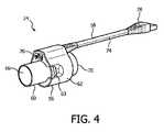
図4は、一実施例に従ったインラインアクセサリアダプタ24の等角図である。図4に見られるように、インラインアクセサリアダプタ24は、滑らかな結合部材56及びジャンパワイヤハーネスアセンブリ58を含む。滑らかな結合部材56は、加熱管アセンブリ22の近接端部36とインラインアクセサリ7との間に滑らかな接続を供給するように構成され、ジャンパワイヤハーネスアセンブリ58は、加熱管アセンブリ22の加熱要素46と圧力生成装置4の出力ポート26との間に電気的な接続を供給するように構成される。 FIG. 4 is an isometric view of the
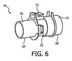
図5は、一実施例に従った滑らかな結合部材56の等角図である。滑らかな結合部材56は、筐体部材62によって囲まれた中央結合部材60を含む。図6は、一実施例に従った中央結合部材60の等角図である。図6に見られるように、中央結合部材60は、図示された実施形態では、標準的なオス型等円すいフィッティングである管状ポート部材66を有する第1の端部64と、図示された実施形態では、標準的なメス型等円すいフィッティングである管状ポート部材70を有する第2の端部68とを含む。また、中央結合部材60は、ジャンパワイヤハーネスアセンブリ58のコネクタ部材を受けるとともに保持するコネクタ筐体72と、加熱管アセンブリ22のタブ部材53を受けるとともに一致するスロット部材63とを含む。 FIG. 5 is an isometric view of a
図7は、一実施例に従ったジャンパワイヤハーネスアセンブリ58の等角図である。ジャンパワイヤハーネスアセンブリ58は、複数のワイヤを有するケーブル部材74と、ケーブル部材74の第1の端部に設けられる第1の電気コネクタ76と、ケーブル部材74の第2の端部に設けられる第2の電気コネクタ78とを含む。インラインアクセサリアダプタ24は、第1の電気コネクタ76が、中央結合部材60のコネクタ筐体72内に受けられる態様で、ケーブル部材74の第1の端部を筐体部材62の中に挿入することにって組み立てられる。 FIG. 7 is an isometric view of jumper
導管アセンブリ6の個別部品の各々について述べてきたが、一実施例に従った導管アセンブリ6のアセンブリが、説明される。まず、インラインアクセサリアダプタ24は、加熱管アセンブリ22の近接端部36に結合される。より具体的には、インラインアクセサリアダプタ24の管状ポート部材66は、加熱管アセンブリ22の管状ポート部材50に結合され、タブ部材53は、スロット部材63の中に挿入される。加えて、加熱管アセンブリ22の電気コネクタ54は、インラインアクセサリアダプタ24のケーブル部材74の第1の端部に設けられた第1の電気コネクタ76に結合される。次に、インラインアクセサリ7の第1の端部は、インラインアクセサリアダプタ24の管状ポート部材70に滑らかに結合される。非限定的な実施例では、インラインアクセサリ7は、管状ポート部材70に結合されるオス型フィッティング9を有する。インラインアクセサリ7の第2の端部は、出力ポート26の管状ポート部材30に滑らかに結合される。非限定的な実施例では、インラインアクセサリ7は、管状ポート部材30に結合されるメス型フィッティング11を有する。以上より、加熱管アセンブリ22が、インラインアクセサリアダプタ24を通じて圧力生成装置4の出力ポート26に滑らかに結合されることとなる。最後に、インラインアクセサリアダプタ24のケーブル部材74の第2の端部に設けられる第2の電気コネクタ78は、出力ポート26の電気コネクタ34に結合される。以上より、加熱管アセンブリ22の加熱要素46が、インラインアクセサリアダプタ24を通じて圧力生成装置4の出力ポート26に(ひいては、圧力生成装置4の電源に)電気的に結合されることとなる。 Having described each of the individual parts of the
従って、上記のインラインアクセサリアダプタ24は、所要の電気的接続を、加熱管機能を有する出力ポート26と加熱管アセンブリ22との間に作ることを可能とするとともに、同時に、インラインアクセサリ7が、ユーザへのフロー経路に挿入されるような、容易に使用できる機構を供給する。 Thus, the in-
図8は、本発明の代替的な一実施例に従った富化アダプタ80の等角図である。富化アダプタ80は、出力ポート26から加熱管アセンブリ22への電気的接続を同時に可能にするとともに、酸素又は他の追加気体が、患者インタフェース装置8へのフロー経路に加えられることを可能にするため、図1の導管アセンブリ6のインラインアクセサリアダプタ24及びインラインアクセサリ7に代替できる。 FIG. 8 is an isometric view of the
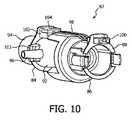
富化アダプタ80は、筐体部材84によって囲まれた中央アダプタアセンブリ82を含む。図9は、一実施例に従った中央アダプタアセンブリ82の前面側等角図であり、図10は、一実施例に従った中央アダプタアセンブリ82の背面側等角図である。図9及び図10に見られるように、中央アダプタアセンブリ82は、第1の端部84と、第2の端部86と、ワイヤハーネスアセンブリ98とを含む。第2の端部86は、構造において、加熱管アセンブリ22の近接端部36と類似しており、出力ポート26のスロット部材33と一致するように構成された管状ポート部材88(図示された実施形態では、標準的なメス型等円すいフィッティング)とタブ部材89とを含む。図9及び図10に見られるように、また、以下より詳細に説明されるように、第2の端部86は、第2の端部が、圧力生成装置4の出力ポート26に、滑らかに、且つ、電気的に結合されることを可能とするために、ワイヤハーネスアセンブリ98の第1の電気コネクタ100を保持するように構成される。第1の端部84は、図示される実施形態では、標準的なオス型等円すいフィッティングである管状ポート部材94を有する結合部材92と、酸素などの追加的な気体が患者インタフェース装置8のフロー経路へ導入されるように、結合部材92によって規定される内部チャンバへのアクセスを与える気体注入ポート96と、ワイヤハーネスアセンブリ98の第2のコネクタ部材104を受けるとともに保持するためのコネクタ筐体102と、加熱管アセンブリのタブ部材53と一致するように構成されるスロット部材103とを含む。このため、第1の端部84は、加熱管アセンブリ22の近接端部36に滑らかに且つ電気的に結合されるように構成される。図示される実施例における第2の端部86は、圧力生成装置4が動作していない場合に圧力生成装置4の中へ追加的な気体が逆流するのを防止するように構成された逆流防止圧力バルブ106を更に含む。 Enriched
従って、上記の富化アダプタ80は、加熱管アセンブリ22と出力ポート26との間に挿入され得る装置であって、挿入された場合に、以下の(i)〜(iii)を同時に供給する、即ち、
(i)圧力生成装置4から加熱管アセンブリ22への主流体経路、
(ii)追加的な気体が主流体経路の中に挿入されるための第2の経路、
(iii)ハーネスアセンブリ98形式のジャンパによる出力ポート26から加熱管アセンブリ22への電気的な接続。Therefore, the above-described
(I) a main fluid path from the pressure generator 4 to the
(Ii) a second path for additional gas to be inserted into the main fluid path;
(Iii) Electrical connection from the
さらに、図示された実施形態では、インラインアクセサリアダプタ24及び富化アダプタ80が加熱管アセンブリ22とともに用いられることが説明されたが、本発明は、加熱管の使用のみに限定されないことが理解されるであろう。むしろ、インラインアクセサリアダプタ24及び富化アダプタ80は、これに限定されないが、患者インタフェース装置からベースユニットに、及び/又は、ベースユニットから患者インタフェース装置に、電気信号を伝達するための1又は複数のワイヤを含む電気管アセンブリなどの、電気的接続が作られる任意のタイプの電気管アセンブリとともに使用されてもよい。 Furthermore, while the illustrated embodiment has been described with the in-
請求項中の括弧内の任意の参照符号は、請求項を限定するものとして解釈されるべきではない。「有する」又は「含む」なる用語は、請求項に挙げられた要素又はステップ以外の要素又はステップの存在を除外しない。幾つかの手段を規定している装置クレームにおいて、これらの手段の幾つかは、全く同一のハードウェアによって実現されてもよい。単数形の要素は、かかる要素が複数存在することを除外しない。幾つかの手段を規定している任意の装置クレームにおいて、これらの手段の幾つかは、全く同一のハードウェア部品によって実現されてもよい。特定の要素が相互に異なる従属項において言及されているという単なる事実は、これらの要素が組み合わせられないということを示すものではない。 Any reference sign between parentheses in the claim should not be construed as limiting the claim. The terms “comprising” or “including” do not exclude the presence of elements or steps other than those listed in a claim. In the device claim defining several means, some of these means may be realized by one and the same piece of hardware. An element in the singular does not exclude the presence of a plurality of such elements. In any device claim defining several means, some of these means may be realized by one and the same hardware component. The mere fact that certain elements are recited in mutually different dependent claims does not indicate that these elements cannot be combined.
現時点で最も実用的且つ好適と考えられる実施態様に基づき例示の目的のために本発明を詳細に記載したが、そのような詳細は専らその目的のためであること、並びに、本発明は開示の実施態様に限定されず、逆に、付属の請求項の精神及び範囲内にある変更及び均等構成を包含することが意図されていることが理解されるべきである。例えば、本発明は、可能な限り、任意の実施態様の1つ又はそれよりも多くの機能を任意の他の実施態様の1つ又はそれよりも多くのの機能と組み合わせ得ることが理解されるべきである。 Although the present invention has been described in detail for purposes of illustration based on the most practical and preferred embodiment at the present time, such details are solely for that purpose and the present invention is not disclosed. It should be understood that the invention is not limited to the embodiments but, conversely, is intended to encompass modifications and equivalent arrangements that fall within the spirit and scope of the appended claims. For example, it is understood that the present invention can combine one or more functions of any embodiment with one or more functions of any other embodiment whenever possible. Should.
Claims (10)
Translated fromJapanese前記電気管アセンブリに滑らかに結合される第1のポート部材を有する第1の端部と、
前記圧力生成装置によって生成される呼吸ガスのフローを受ける第2のポート部材を有する第2の端部と、
前記電気管アセンブリと前記圧力生成装置との間に電気的な接続を与えるために、前記電気管アセンブリに電気的に結合される第1の電気コネクタと、前記圧力生成装置に電気的に結合される第2の電気コネクタとを有するワイヤアセンブリと、
前記タブ部材の構成とマッチする構成を持つ第2のスロット部材であって、前記電気管アセンブリが前記アダプタ装置に接続されることを可能にするため、前記電気管アセンブリの前記タブ部材と係合するように構成された前記第2のスロット部材と、
を有し、
前記アダプタ装置は、前記第1のポート部材を通じて前記呼吸ガスのフローを前記電気管アセンブリに運ぶ、及び
前記アダプタ装置はさらに、インラインアクセサリ装置を有し、
前記インラインアクセサリ装置は、前記インラインアクセサリ装置の第1の端部において、前記第2のポート部材に滑らかに結合されるポート部材、及び前記インラインアクセサリ装置の第2の端部において、前記圧力生成装置の前記出力ポートに滑らかに結合されるポート部材を有し、前記ワイヤアセンブリは、前記インラインアセンブリ装置の長さ方向に沿って延在する、並びに
前記インラインアクセサリ装置は、酸素富化アダプタ、圧力バルブ又はバクテリアフィルタを有する、
アダプタ装置。An adapter device for a respiratory therapy system having a pressure generating device and an electrical tube assembly coupled to a patient interface device, the pressure generating device having the electrical tube assembly connected to a first housing. Including an output port having the first housing with a firstslot member configured to engage atab member of the electrical tube assembly, the adapter device comprising:
A first end having a first port member smoothly coupled to the electrical tube assembly;
A second end having a second port member for receiving a flow of breathing gas generated by the pressure generating device;
A first electrical connector electrically coupled to the electrical tube assembly and electrically coupled to the pressure generating device to provide an electrical connection between the electrical tube assembly and the pressure generating device. A wire assembly having a second electrical connector;
Asecond slot member having a structure which constitutes a matching of thetab member, to allow the said electrical tube assembly is connected to the adapter device, saidtab member engages the electrical tube assembly Saidsecond slot member configured to:
Have
The adapter device carries the flow of breathing gas through the first port member to the electrical tube assembly;and
The adapter device further includes an inline accessory device;
The inline accessory device includes a port member that is smoothly coupled to the second port member at a first end of the inline accessory device, and the pressure generating device at a second end of the inline accessory device. A port member that is smoothly coupled to the output port, wherein the wire assembly extends along a length of the in-line assembly device, and
The in-line accessory device comprises an oxygen-enriched adapter, a pressure valve or a bacterial filter;
Adapter device.
患者インタフェース装置と、
遠位端において前記患者インタフェース装置に結合される電気管アセンブリであって、前記電気管アセンブリは、その近位端において供給された第2の筐体を持ち、前記第2の筐体は、電気コネクタ及びタブ部材を持ち、前記電気管アセンブリの前記電気コネクタは、前記圧力生成装置から前記電気管アセンブリに電力信号及び/又は制御信号が供給されることを可能にするため、前記圧力生成装置の前記電気コネクタに結合されるように構成され、前記タブ部材は、前記第2の筐体が前記第1の筐体に接続されることを可能にするため、前記第1のスロット部材と係合するように構成される、前記電気管アセンブリと、
前記圧力生成装置と前記電気管アセンブリとの間に設けられるアダプタ装置と、を有し、
前記アダプタ装置が、
前記電気管アセンブリに滑らかに結合される第1のポート部材を有する第1の端部と、
前記呼吸ガスのフローを受ける第2のポート部材を有する第2の端部と、
前記電気管アセンブリと前記圧力生成装置との間に電気的な接続を与えるために、前記電気管アセンブリの前記電気コネクタに電気的に結合される第1の電気コネクタと、前記圧力生成装置の前記電気コネクタに電気的に結合される第2の電気コネクタとを有するワイヤアセンブリと、
前記タブ部材の構成とマッチする構成を持つ第2のスロット部材であって、前記第2の筐体を前記アダプタ装置に接続するため、前記電気管アセンブリの前記タブ部材と係合する前記第2のスロット部材と、
を有し、
前記アダプタ装置は、前記第1のポート部材を通じて、前記電気管アセンブリに前記呼吸ガスのフローを運ぶ、及び
前記アダプタ装置はさらに、インラインアクセサリ装置を有し、
前記インラインアクセサリ装置は、前記インラインアクセサリ装置の第1の端部において、前記第2のポート部材に滑らかに結合されるポート部材、及び前記インラインアクセサリ装置の第2の端部において、前記圧力生成装置の前記出力ポートに滑らかに結合されるポート部材を有し、前記ワイヤアセンブリは、前記インラインアセンブリ装置の長さ方向に沿って延在する、並びに
前記インラインアクセサリ装置は、酸素富化アダプタ、圧力バルブ又はバクテリアフィルタを有する、
呼吸療法システム。A pressure generating device for generating a flow of breathing gas, the pressure generating device including anoutput port having a first housing withan electrical connector and a firstslot member;
A patient interface device;
An electrical tube assembly coupled to the patient interface device at a distal end, the electrical tube assembly having a second housing supplied at a proximal end thereof, wherein the second housing iselectrically Having a connector and atab member,wherein the electrical connector of the electrical tube assembly allows a power signal and / or a control signal to be supplied from the pressure generator to the electrical tube assembly; Thetab member is configured to be coupled to the electrical connector, and thetab member engages with the firstslot member to allow the second housing to be connected to the first housing. The electrical tube assembly configured to:
An adapter device provided between the pressure generating device and the electric tube assembly,
The adapter device is
A first end having a first port member smoothly coupled to the electrical tube assembly;
A second end having a second port member for receiving the flow of breathing gas;
To provide an electrical connection between the pressure generating device and the electrical tube assembly, afirst electrical connector electrically coupled tothe electrical connector of the electrical tube assembly,the said pressure generating device awire assembly having asecond electrical connector electrically coupled to theelectrical connector,
Saidtab member and asecond slot member having a configuration that matches the configuration of, for connecting the second housing to the adapter device, thesecond that engages thetab member of said electrical tube assemblyA slot member of
Have
It said adapterdevice, through the first port member, carry a flow of the breathing gas to the electric tube assembly,and
The adapter device further includes an inline accessory device;
The inline accessory device includes a port member that is smoothly coupled to the second port member at a first end of the inline accessory device, and the pressure generating device at a second end of the inline accessory device. A port member that is smoothly coupled to the output port, wherein the wire assembly extends along a length of the in-line assembly device, and
The in-line accessory device comprises an oxygen-enriched adapter, a pressure valve or a bacterial filter;
Respiratory therapy system.
Applications Claiming Priority (3)
| Application Number | Priority Date | Filing Date | Title |
|---|---|---|---|
| US201261740217P | 2012-12-20 | 2012-12-20 | |
| US61/740,217 | 2012-12-20 | ||
| PCT/IB2013/061037WO2014097145A1 (en) | 2012-12-20 | 2013-12-17 | Inline adapter for a respiratory therapy device |
Publications (3)
| Publication Number | Publication Date |
|---|---|
| JP2016501608A JP2016501608A (en) | 2016-01-21 |
| JP2016501608A5 JP2016501608A5 (en) | 2017-02-02 |
| JP6378199B2true JP6378199B2 (en) | 2018-08-22 |
Family
ID=50001064
Family Applications (1)
| Application Number | Title | Priority Date | Filing Date |
|---|---|---|---|
| JP2015548835AActiveJP6378199B2 (en) | 2012-12-20 | 2013-12-17 | Inline adapter for respiratory therapy equipment |
Country Status (8)
| Country | Link |
|---|---|
| US (1) | US9974917B2 (en) |
| EP (2) | EP3034122B1 (en) |
| JP (1) | JP6378199B2 (en) |
| CN (1) | CN104870042B (en) |
| AU (1) | AU2013365825B2 (en) |
| BR (1) | BR112015014324B1 (en) |
| RU (1) | RU2657953C2 (en) |
| WO (1) | WO2014097145A1 (en) |
Families Citing this family (45)
| Publication number | Priority date | Publication date | Assignee | Title |
|---|---|---|---|---|
| ES2935418T3 (en) | 2011-08-10 | 2023-03-06 | Fisher & Paykel Healthcare Ltd | Conduit connector for a patient breathing device |
| USD747471S1 (en) | 2012-08-10 | 2016-01-12 | Fisher & Paykel Healthcare Limited | Connector |
| USD738489S1 (en) | 2013-05-31 | 2015-09-08 | Resmed Limited | Positive airway pressure delivery console |
| USD738488S1 (en) | 2013-05-31 | 2015-09-08 | Resmed Limited | Positive airway pressure delivery console |
| USD743556S1 (en) | 2014-02-19 | 2015-11-17 | Resmed Limited | Positive airway pressure delivery console |
| USD744108S1 (en) | 2014-02-19 | 2015-11-24 | Resmed Limited | Humidifier reservoir for positive airway pressure delivery console |
| USD762843S1 (en)* | 2014-03-18 | 2016-08-02 | Resmed Limited | Air delivery tube |
| USD760258S1 (en) | 2014-05-30 | 2016-06-28 | Resmed Limited | Display screen with graphical user interface |
| CN112316272B (en)* | 2014-07-07 | 2023-10-31 | 费雪派克医疗保健有限公司 | Medical tube and connector for gas delivery system |
| USD809124S1 (en) | 2014-09-12 | 2018-01-30 | Resmed Limited | Pressurized air delivery console |
| USD790683S1 (en) | 2015-03-11 | 2017-06-27 | Resmed Limited | Pressurized air delivery console |
| US11446462B2 (en) | 2015-03-31 | 2022-09-20 | Fisher & Paykel Healthcare Limited | Apparatus for use in a respiratory support system |
| WO2017037660A1 (en)* | 2015-09-04 | 2017-03-09 | Fisher & Paykel Healthcare Limited | Connectors for conduits |
| USD807995S1 (en)* | 2015-09-22 | 2018-01-16 | Fisher & Paykel Healthcare Limited | Circuit kit for a humidifier |
| USD841147S1 (en)* | 2015-09-30 | 2019-02-19 | Fisher & Paykel Healthcare Limited | Circuit kit for a humidifier |
| USD805630S1 (en) | 2016-02-02 | 2017-12-19 | Resmed Limited | Air delivery tube |
| USD809656S1 (en) | 2016-06-10 | 2018-02-06 | Fisher & Paykel Healthcare Limited | Connector for a breathing circuit |
| USD841148S1 (en)* | 2016-07-21 | 2019-02-19 | Fisher & Paykel Healthcare Limited | Breathing tube |
| US10953185B2 (en)* | 2017-03-31 | 2021-03-23 | Koninklijke Philips N.V. | Moisture wicking conduit and system |
| USD895788S1 (en)* | 2018-01-30 | 2020-09-08 | Inovytec Medical Solutions Ltd. | Patient circuit for gas delivery |
| JP2021518215A (en)* | 2018-03-20 | 2021-08-02 | アイデヤ ラブズ, エルエルシー | Positive pressure respiratory oil delivery system |
| DE102018126886A1 (en)* | 2018-10-19 | 2020-04-23 | Eugen Forschner Gmbh | Connection arrangement |
| EP3877028A4 (en)* | 2018-11-05 | 2022-08-10 | Fisher & Paykel Healthcare Limited | Breathing assistance apparatus and/or components thereof |
| CN113038984B (en)* | 2018-11-16 | 2024-07-05 | 皇家飞利浦有限公司 | Valve for pressure support system |
| USD958968S1 (en)* | 2018-11-28 | 2022-07-26 | Fisher & Paykel Healthcare Limited | Breathing tube with mesh |
| USD921900S1 (en) | 2018-12-19 | 2021-06-08 | ResMed Pty Ltd | Humidification tub |
| CN217067329U (en)* | 2019-07-08 | 2022-07-29 | 费雪派克医疗保健有限公司 | Medical tube assembly |
| WO2021010027A1 (en)* | 2019-07-12 | 2021-01-21 | 株式会社村田製作所 | Cpap device |
| US10737049B1 (en)* | 2019-08-05 | 2020-08-11 | Dynasthetics, Llc | Apparatus for connecting oxygen delivery control instrument to patient delivery device |
| USD1006981S1 (en) | 2019-09-06 | 2023-12-05 | Fisher & Paykel Healthcare Limited | Breathing conduit |
| USD948027S1 (en) | 2019-09-10 | 2022-04-05 | Fisher & Paykel Healthcare Limited | Connector for a breathing conduit |
| EP4051351A1 (en)* | 2019-10-31 | 2022-09-07 | ResMed Sensor Technologies Limited | Systems and methods for injecting substances into a respiratory system |
| USD949295S1 (en)* | 2020-02-26 | 2022-04-19 | Soclean Inc. | Connector for a sanitizing machine |
| USD957589S1 (en)* | 2020-02-26 | 2022-07-12 | Soclean, Inc. | Connector for a sanitizing machine |
| USD944938S1 (en)* | 2020-02-26 | 2022-03-01 | Soclean, Inc. | Connector for a sanitizing machine |
| USD944939S1 (en)* | 2020-02-26 | 2022-03-01 | Soclean, Inc. | Connector for a sanitizing machine |
| USD944941S1 (en)* | 2020-02-27 | 2022-03-01 | Soclean, Inc. | Connector for a sanitizing machine |
| USD940861S1 (en) | 2020-03-03 | 2022-01-11 | Fisher & Paykel Healthcare Limited | Connector for a respiratory system conduit |
| JP7723089B2 (en)* | 2020-11-03 | 2025-08-13 | レスメド・プロプライエタリー・リミテッド | Respiratory Pressure Therapy Device |
| USD974551S1 (en) | 2020-12-09 | 2023-01-03 | Fisher & Paykel Healthcare Limited | Connector assembly and connector |
| US11986592B2 (en) | 2021-05-14 | 2024-05-21 | Dynasthetics, Llc | Electronic firebreak systems and methods for use with oxygen delivery device |
| USD1073919S1 (en) | 2021-05-17 | 2025-05-06 | Fisher & Paykel Healthcare Limited | Respiratory system conduit with connector |
| USD995758S1 (en) | 2021-06-11 | 2023-08-15 | Fisher & Paykel Healthcare Limited | Tube assembly and connector |
| USD1064254S1 (en) | 2021-10-21 | 2025-02-25 | Hamilton Medical Ag | Breathing tube for medical respiratory apparatus |
| CN114848993B (en)* | 2022-06-06 | 2025-09-02 | 深圳市普博医疗科技股份有限公司 | Fluid connection devices and ventilation equipment |
Family Cites Families (21)
| Publication number | Priority date | Publication date | Assignee | Title |
|---|---|---|---|---|
| JPH08317983A (en)* | 1995-03-17 | 1996-12-03 | Teijin Ltd | Aspirating gas supplying apparatus |
| WO1999008738A1 (en)* | 1997-08-14 | 1999-02-25 | Resmed Limited | An apparatus and method for supplying on-demand additional breathable gas |
| SE9704663D0 (en)* | 1997-12-15 | 1997-12-15 | Siemens Elema Ab | Fan system |
| DE19958296C1 (en)* | 1999-12-03 | 2001-09-20 | Map Gmbh | Heated breathing tube for patient has heating element formed by tube wall and consisting of layer of electrically conductive synthetic material, voltage supply line integrated into tube wall |
| SE0000605D0 (en)* | 2000-02-24 | 2000-02-24 | Siemens Elema Ab | Conduit for connecting a fluid transfer device to a patient |
| US7120354B2 (en) | 2000-03-21 | 2006-10-10 | Fisher & Paykel Healthcare Limited | Gases delivery conduit |
| DE10134725A1 (en)* | 2001-07-17 | 2003-02-06 | Weinmann G Geraete Med | Device for filtering breathing air |
| DE102005000922A1 (en) | 2005-01-07 | 2006-07-20 | Seleon Gmbh | Aerial goggles, nosepiece, Y-piece and procedures |
| US8522782B2 (en)* | 2005-09-12 | 2013-09-03 | Mergenet Medical, Inc. | High flow therapy device utilizing a non-sealing respiratory interface and related methods |
| CN101365509A (en)* | 2005-12-14 | 2009-02-11 | 莫哲奈特医疗公司 | High flow therapy device |
| CN101541367B (en)* | 2006-11-08 | 2014-02-26 | 雷斯梅德有限公司 | Catheters used in breathing apparatus |
| EP2079505B1 (en)* | 2006-11-08 | 2020-07-15 | ResMed Pty Ltd | Conduit for use in a respiratory apparatus |
| WO2008074058A1 (en) | 2006-12-21 | 2008-06-26 | Resmed Ltd | A connector |
| WO2008105257A1 (en)* | 2007-02-26 | 2008-09-04 | Nec Corporation | High-frequency circuit |
| MX2010001827A (en)* | 2007-08-14 | 2010-06-01 | Plastiflex Belgium | A respiratory system. |
| CN102196837B (en) | 2008-08-22 | 2015-09-09 | 呼吸科技公司 | Methods and devices for providing mechanical ventilation utilizing an open airway interface |
| AU2010206053B2 (en)* | 2009-07-31 | 2014-08-07 | ResMed Pty Ltd | Wire Heated Tube with Temperature Control System, Tube Type Detection, and Active Over Temperature Protection for Humidifier for Respiratory Apparatus |
| JP6097689B2 (en)* | 2010-09-06 | 2017-03-15 | レスメド・リミテッドResMed Limited | Method and apparatus for preventing rainout |
| WO2012160477A1 (en)* | 2011-05-20 | 2012-11-29 | Koninklijke Philips Electronics N.V. | Rotating electrical connector and respiratory gas delivery system employing same |
| WO2013012696A1 (en) | 2011-07-15 | 2013-01-24 | Inceptus, Inc. | Systems, methods and devices for ozone sanitization of continuous positive airway pressure devices |
| CA3207604A1 (en)* | 2012-04-05 | 2013-10-10 | Fisher & Paykel Healthcare Limited | Breathing assistance apparatus with serviceability features |
- 2013
- 2013-12-17JPJP2015548835Apatent/JP6378199B2/enactiveActive
- 2013-12-17USUS14/646,740patent/US9974917B2/enactiveActive
- 2013-12-17EPEP15200001.4Apatent/EP3034122B1/enactiveActive
- 2013-12-17AUAU2013365825Apatent/AU2013365825B2/enactiveActive
- 2013-12-17RURU2015129059Apatent/RU2657953C2/enactive
- 2013-12-17BRBR112015014324-5Apatent/BR112015014324B1/enactiveIP Right Grant
- 2013-12-17EPEP13824204.5Apatent/EP2934644B1/enactiveActive
- 2013-12-17CNCN201380067180.9Apatent/CN104870042B/enactiveActive
- 2013-12-17WOPCT/IB2013/061037patent/WO2014097145A1/enactiveApplication Filing
Also Published As
| Publication number | Publication date |
|---|---|
| BR112015014324A2 (en) | 2017-07-11 |
| BR112015014324B1 (en) | 2021-05-18 |
| US20150306332A1 (en) | 2015-10-29 |
| EP3034122A1 (en) | 2016-06-22 |
| RU2015129059A (en) | 2017-01-26 |
| AU2013365825A1 (en) | 2015-08-06 |
| AU2013365825B2 (en) | 2018-07-12 |
| CN104870042B (en) | 2019-01-22 |
| US9974917B2 (en) | 2018-05-22 |
| EP3034122B1 (en) | 2020-09-16 |
| WO2014097145A1 (en) | 2014-06-26 |
| EP2934644A1 (en) | 2015-10-28 |
| CN104870042A (en) | 2015-08-26 |
| RU2657953C2 (en) | 2018-06-18 |
| EP2934644B1 (en) | 2019-02-27 |
| JP2016501608A (en) | 2016-01-21 |
Similar Documents
| Publication | Publication Date | Title |
|---|---|---|
| JP6378199B2 (en) | Inline adapter for respiratory therapy equipment | |
| JP6878643B2 (en) | Outlet connection assembly and how to form the assembly | |
| US7353826B2 (en) | Sealing nasal cannula | |
| US9717873B2 (en) | Rotating electrical connector ADN respiratory gas delivery system employing same | |
| CN104853796B (en) | Rotating fluid connector | |
| CN113101475B (en) | Respiratory pressure therapy device | |
| CN110944704B (en) | Respiratory user interface | |
| CN106029146B (en) | Head frame conduit assembly and integrated pressure sensing | |
| TW202412872A (en) | Medical tube | |
| JP2014532500A (en) | Modular patient interface device with chamber and nasal pillow assembly | |
| JP2025142063A (en) | Heat and moisture exchanger with flexible frame for patient interface | |
| CN116322851A (en) | Exhaust device for patient interface device and patient interface including same | |
| US10507299B2 (en) | Releasable elbow connector | |
| JP2019528906A (en) | Magnetic anti-crash function for conduit | |
| US20210128863A1 (en) | Nasal cannula and tubing with ventilator system | |
| JP2023505371A (en) | Mask and tube adapters for patient interface devices and patient interface devices including adapters | |
| HK1158556A (en) | Sealing nasal cannula |
Legal Events
| Date | Code | Title | Description |
|---|---|---|---|
| A521 | Request for written amendment filed | Free format text:JAPANESE INTERMEDIATE CODE: A523 Effective date:20161214 | |
| A621 | Written request for application examination | Free format text:JAPANESE INTERMEDIATE CODE: A621 Effective date:20161214 | |
| RD04 | Notification of resignation of power of attorney | Free format text:JAPANESE INTERMEDIATE CODE: A7424 Effective date:20170214 | |
| A977 | Report on retrieval | Free format text:JAPANESE INTERMEDIATE CODE: A971007 Effective date:20170929 | |
| A131 | Notification of reasons for refusal | Free format text:JAPANESE INTERMEDIATE CODE: A131 Effective date:20171017 | |
| A601 | Written request for extension of time | Free format text:JAPANESE INTERMEDIATE CODE: A601 Effective date:20180110 | |
| A521 | Request for written amendment filed | Free format text:JAPANESE INTERMEDIATE CODE: A523 Effective date:20180411 | |
| TRDD | Decision of grant or rejection written | ||
| A01 | Written decision to grant a patent or to grant a registration (utility model) | Free format text:JAPANESE INTERMEDIATE CODE: A01 Effective date:20180703 | |
| A61 | First payment of annual fees (during grant procedure) | Free format text:JAPANESE INTERMEDIATE CODE: A61 Effective date:20180726 | |
| R150 | Certificate of patent or registration of utility model | Ref document number:6378199 Country of ref document:JP Free format text:JAPANESE INTERMEDIATE CODE: R150 | |
| R250 | Receipt of annual fees | Free format text:JAPANESE INTERMEDIATE CODE: R250 | |
| R250 | Receipt of annual fees | Free format text:JAPANESE INTERMEDIATE CODE: R250 | |
| R250 | Receipt of annual fees | Free format text:JAPANESE INTERMEDIATE CODE: R250 | |
| R250 | Receipt of annual fees | Free format text:JAPANESE INTERMEDIATE CODE: R250 | |
| R250 | Receipt of annual fees | Free format text:JAPANESE INTERMEDIATE CODE: R250 |