JP6377191B2 - Digital broadcast receiver - Google Patents
Digital broadcast receiverDownload PDFInfo
- Publication number
- JP6377191B2 JP6377191B2JP2017020825AJP2017020825AJP6377191B2JP 6377191 B2JP6377191 B2JP 6377191B2JP 2017020825 AJP2017020825 AJP 2017020825AJP 2017020825 AJP2017020825 AJP 2017020825AJP 6377191 B2JP6377191 B2JP 6377191B2
- Authority
- JP
- Japan
- Prior art keywords
- channel
- broadcast
- unit
- broadcasting
- scan
- Prior art date
- Legal status (The legal status is an assumption and is not a legal conclusion. Google has not performed a legal analysis and makes no representation as to the accuracy of the status listed.)
- Active
Links
Images


Landscapes
- Circuits Of Receivers In General (AREA)
- Television Receiver Circuits (AREA)
- Two-Way Televisions, Distribution Of Moving Picture Or The Like (AREA)
Description
Translated fromJapanese本発明は、デジタル放送受信装置に関する。 The present invention relates to a digital broadcast receiving apparatus.
一般に、デジタル放送受信装置は、デジタル放送に割り振られている電波の周波数帯域において予めチャンネルスキャンを実行して、視聴可能チャンネルを予め記憶(プリセット)している。チャンネルスキャンを実施している期間には、放送番組が一時的に視聴できない又は受信性能が一時的に低下することがあるため、チャンネルスキャンに要する時間は短時間であることが望ましい。チャンネルスキャンに要する時間を短縮する技術として、例えば、特許文献1に記載された技術がある。この技術を採用したデジタル放送受信装置は、2つの受信系統を備え、チャンネルスキャンの対象となる周波数帯域の全体を2つの受信系統で分担し、2つの受信系統の各々は分担された周波数帯域の各々に対してチャンネルスキャンを実施する。このチャンネルスキャンにおいて2つの受信系統の各々が対象とする放送方式のチャンネルを検出することができなかったときには、チャンネルスキャンの対象とする放送方式以外の放送方式のチャンネルのチャンネル番号(物理チャンネル)を、互いに他方の受信系統に渡す。そして、2つの受信系統の各々は、次のチャンネルスキャンにおいて、他方の受信系統から渡されたチャンネル番号のチャンネルをスキャンする。 Generally, a digital broadcast receiving apparatus performs channel scan in advance in a frequency band of radio waves allocated to digital broadcast, and stores (presets) viewable channels in advance. During the period when the channel scan is performed, it is desirable that the time required for the channel scan is short because the broadcast program cannot be temporarily viewed or the reception performance may be temporarily deteriorated. As a technique for shortening the time required for channel scanning, for example, there is a technique described in
特許文献1に記載されたデジタル放送受信装置は、2つの受信系統が周波数帯域を分担してチャンネルスキャンを実施することでチャンネルスキャンに要する時間の短縮を実現しているものの、2つの受信系統が並行してチャンネルスキャンを行う必要があるという問題がある。その結果、受信系統が2系統の場合には、チャンネルスキャンを実施している期間は放送番組の視聴ができなくなる。 Although the digital broadcast receiving apparatus described in
そこで、本発明は、上記従来技術の課題を解決するためになされたものであり、1系統の受信系統でチャンネルスキャンを実施でき、且つ、チャンネルスキャンに要する時間を短縮することができるデジタル放送受信装置を提供することを目的とする。 Accordingly, the present invention has been made to solve the above-described problems of the prior art, and can perform channel scanning with a single receiving system and can reduce the time required for channel scanning. An object is to provide an apparatus.
本発明の一態様に係るデジタル放送受信装置は、複数の放送方式のデジタル放送を受信可能に構成されたチューナ部と、前記複数の放送方式に対応する複数の復調処理ロジックのいずれかに切替可能であり、前記チューナ部から出力された信号を復調する復調部と、前記復調部が出力したストリームから選局情報を分離するデマルチプレクス部と、前記チューナ部、前記復調部及び前記デマルチプレクス部を制御してチャンネルスキャン処理を実行するスキャン制御部と、記憶部とを備え、前記チャンネルスキャン処理では、前記複数の放送方式の中から、前記復調部における復調処理時間が短い放送方式を選択し、前記選択された放送方式を第1の放送方式とし、前記複数の放送方式の内の前記第1の放送方式及び第2の放送方式のデジタル放送の周波数帯域の全体に対するチャンネルスキャンを実行し、前記第1の放送方式の視聴可能チャンネルを検出して前記記憶部に登録し、前記チャンネルスキャンの過程で、前記第1の放送方式の視聴可能チャンネルではないが受信電力がある閾値以上存在する場合に、前記第2の放送方式の視聴可能チャンネルかを検出する処理を実施し、該視聴可能チャンネルであった場合に前記第2の放送方式の視聴可能チャンネルとして前記記憶部に登録することを特徴とする。The digital broadcast receiving apparatus according to one aspect of the present invention can be switched between a tuner configured to receive digital broadcasts of a plurality of broadcast systems and a plurality of demodulation processing logics corresponding to the plurality of broadcast systems. A demodulator that demodulates the signal output from the tuner, a demultiplexer that separates channel selection information from the stream output from the demodulator, the tuner, the demodulator, and the demultiplexer A scan control unit that controls a unit to execute a channel scan process, and a storage unit, and in the channel scan process,a broadcast system with a short demodulation time in the demodulator is selected from the plurality of broadcast systems and, a broadcasting system that the selected the first broadcast system, digital ofthe first broadcasting system and the second broadcasting system among the plurality of broadcast systems A channel scan is performed on the entire broadcast frequency band, a viewable channel of the first broadcast system is detected and registered in the storage unit, and the first broadcast system can be viewed in the course of the channel scan. If the received power is not a channel but exceeds a certain threshold value, a process of detecting whether the channel is a viewable channel of the second broadcasting system is performed. It is registered in the storage unit as a viewable channel.
本発明においては、第1の放送方式の視聴可能チャンネルを記憶部に登録するための第1の放送方式のデジタル放送に対するチャンネルスキャンおいて、他の放送方式の視聴可能チャンネル候補が検出された場合には、この検出結果を一時記憶した後に又はこの検出の直後に、視聴可能チャンネル候補について第2の放送方式の視聴可能チャンネルであるかの判定をし、第2の放送方式の視聴可能チャンネルであれば記憶部に登録する。このように、本発明においては、第2の放送方式の視聴可能チャンネルの検出を、第1の放送方式のデジタル放送に対するチャンネルスキャンにおいて検出された視聴可能チャンネル候補を利用して行うので、第2の放送方式の視聴可能チャンネルの検出に要する時間を短縮することができる。よって、本発明によれば、複数の放送方式の視聴可能チャンネルを検出し登録するための処理に要する時間を短縮することができる。 In the present invention, in a channel scan for the first broadcast system digital broadcast for registering the first broadcast system viewable channel in the storage unit, a viewable channel candidate of another broadcast system is detected. After temporarily storing the detection result or immediately after this detection, it is determined whether the viewable channel candidate is a viewable channel of the second broadcast system, and the viewable channel of the second broadcast system is used. If there is, register it in the storage unit. As described above, in the present invention, since the viewable channel of the second broadcast system is detected using the viewable channel candidates detected in the channel scan for the digital broadcast of the first broadcast system, It is possible to reduce the time required to detect a viewable channel of the broadcasting system. Therefore, according to the present invention, it is possible to reduce the time required for processing for detecting and registering a plurality of broadcast-type viewable channels.
また、本発明においては、1つの受信系統で複数の放送方式の視聴可能チャンネルを検出し登録するので、複数の受信系統を有するデジタル放送受信装置であれば、チャンネルスキャンを実施している期間であっても、放送番組を視聴することができる。 Also, in the present invention, since a plurality of broadcast channels that can be viewed are detected and registered in one reception system, a digital broadcast reception apparatus having a plurality of reception systems can perform the channel scanning period. Even if it exists, the broadcast program can be viewed.
実施の形態1.
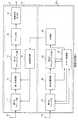
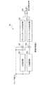
図1は、実施の形態1に係るデジタル放送受信装置1の構成を概略的に示すブロック図である。図1に示されるように、デジタル放送受信装置1は、複数の放送方式のデジタル放送を受信可能な視聴用の受信系統である第1の受信系統10と、複数の放送方式のデジタル放送を受信可能なチャンネルスキャン用の受信系統である第2の受信系統20とを有する。第1の受信系統10は、チューナ部(第1のチューナ部)11と、復調部(第1の復調部)12と、デマルチプレクス部(第1のデマルチプレクス部)13と、デコード部14と、映像音声出力部15と、選局制御部16とを有する。第2の受信系統20は、チューナ部(第2のチューナ部)21と、復調部(第2の復調部)22と、デマルチプレクス部(第2のデマルチプレクス部)23と、記憶部24と、スキャン制御部25と、チャンネル一時記憶部26とを有する。実施の形態1に係るデジタル放送受信装置1は、チャンネルスキャン処理において、複数の放送方式の内の第1の放送方式のデジタル放送の周波数帯域の全体に対するチャンネルスキャンを実行して第1の放送方式の視聴可能チャンネルを検出して記憶部24に登録し、第1の放送方式のデジタル放送の周波数帯域の全体に対するチャンネルスキャンの過程で、受信電力に基づいて複数の放送方式の内の第2の放送方式の視聴可能チャンネル候補を検出してチャンネル一時記憶部26に記憶させる第1フェーズの処理と、チャンネル一時記憶部26に記憶されている第2の放送方式の視聴可能チャンネル候補を対象にチャンネルスキャンを実行して第2の放送方式の視聴可能チャンネルを検出して記憶部24に登録する第2フェーズの処理とを含むことを特徴としている。チャンネルスキャン処理の詳細は、後述する。
FIG. 1 is a block diagram schematically showing a configuration of a digital
第1のチューナ部11は、アンテナ31を介して電波(放送波を含む)を受信する。第1のチューナ部11は、選局制御部16からの指示信号によって指定された物理チャンネル(チャンネル番号)の周波数にチューニングされる。第1のチューナ部11は、アンテナ31を介して受信された電波の内の、チューニングによって選局された周波数の電波に基づく電気信号を生成し、この生成された電気信号を第1の復調部12に与える。 The
第1の復調部12は、第1のチューナ部11から与えられた電気信号に対して復調処理を行って、第1のデジタル信号を生成し、この生成された第1のデジタル信号を第1のデマルチプレクス部13に与える。この第1のデジタル信号は、例えば、DVB−T2(Digital Video Broadcasting−Terrestrial 2)、DVB−T(Digital Video Broadcasting−Terrestrial)、DVB−H(Digital Video Broadcasting−Handheld)、DTMB(Digital Terrestrial Multimedia Broadcast)、CMMB(China Mobile Multimedia Broadcasting)、T−DMB(Terrestrial−Digital Media Broadcasting)、DAB(Digital Audio Broadcast)、ATSC(Advanced Television Systems Committee)、ATSC−M/H(Advanced Television Systems Committee−Mobile/Handheld)、及びISDB−T(Integrated Services Digital Broadcasting−Terrestrial)などの放送方式に準拠したストリームであり、放送方式ごとにストリームのフォーマットが異なる。第1の復調部12は、複数の放送方式の復調が可能に構成されており、選局制御部16から復調対象の信号の放送方式を指示する指示信号が与えられる。この指示信号を受信すると、第1の復調部12は、実施する復調処理を、指定された放送方式の復調処理ロジックに従う復調処理に切り替え、この復調処理ロジックに従う復調処理を開始する。そして、第1の復調部12は、指定された放送方式の信号が検出できたか否かの結果を、選局制御部16に通知する。なお、第1のチューナ部11及び第1の復調部12は、ダイバーシティ処理を行い、1つの第1のデジタル信号を出力するものであってもよい。 The
第1のデマルチプレクス部13は、第1の復調部12によって復調された第1のデジタル信号から特定のサービスの映像圧縮データ及び音声圧縮データを分離し、これらの分離されたデータをデコード部14に与える。 The
デコード部14は、第1のデマルチプレクス部13から与えられた各放送規格で規定された様々な映像圧縮データ及び音声圧縮データを復号する。デコード部14は、復号済みの映像信号及び音声信号を映像音声出力部15に与える。映像音声出力部15は、デコード部14から与えられた映像信号及び音声信号を映像表示装置などのような外部装置に出力する。 The
選局制御部16は、第2の受信系統20で実施されたチャンネルスキャンの結果及び記憶部24に格納されたサービスリストを参照し、ユーザによる操作部からの選択操作などによって指定された選局先サービスについての物理チャンネルを取得する。選局制御部16は、取得された物理チャンネルの周波数にチューニングする処理を指示するための指示信号を第1のチューナ部11に与える。 The channel
第2のチューナ部21は、アンテナ32を介して電波(放送波を含む)を受信して、この受信された電波に基づく電気信号を生成し、この生成された電気信号を第2の復調部22に与える。第2のチューナ部21は、スキャン制御部25からの指示信号によって指定された物理チャンネルの周波数にチューニングされ、その指定された物理チャンネルで受信された電波の受信レベルの判定結果を、スキャン制御部25に通知する。 The
第2の復調部22は、第2のチューナ部21から与えられた電気信号に対して復調処理を行って、第2のデジタル信号を生成し、この生成された第2のデジタル信号を第2のデマルチプレクス部23に与える。この第2のデジタル信号は、例えば、DVB−T2、DVB−T、DVB−H、DTMB、CMMB、T−DMB、DAB、ATSC、ATSC−M/H、及びISDB−Tなどの各放送方式に準拠したストリームであり、放送方式ごとにフォーマットが異なる。第2の復調部22は、複数の放送方式の復調が可能に構成されており、スキャン制御部25から復調対象の信号の放送方式を指示する指示信号が第2の復調部22に与えられる。この指示信号を受信すると、第2の復調部22は、実施する復調処理を、指定された放送方式の復調処理ロジックに従う復調処理に切り替えて、復調処理を開始する。第2の復調部22は、復調処理に際し、例えば、DVB−T2、DVB−T、DVB−H、DTMB、CMMB、T−DMB、DAB、ATSC、ATSC−M/H、及びISDB−Tの内の複数のフレームの同期が確立できた場合にフレームロックしたストリームを出力することができる。また、第2の復調部22は、例えば、フレームロックできたことにより、指定された放送方式を検出することができたと判定し、この判定結果を放送検出可否判定結果としてスキャン制御部25に通知する。なお、第2のチューナ部21及び第2の復調部22は、ダイバーシティ処理を行い、1つの第2のデジタル信号を出力するものであってもよい。 The
第2のデマルチプレクス部23は、復調された第2のデジタル信号から、選局に必要な情報が格納されている番組特定情報及びサービス情報を分離して、分離された番組特定情報及びサービス情報をスキャン制御部25に与える。例えば、ストリームがトランスポートストリーム(TS)の場合には、番組特定情報及びサービス情報は、PSI(Program−specific information)データ及びSI(Service Information)に相当する情報、すなわち、PSI/SIデータである。 The
記憶部24は、複数の放送方式で放送されるサービスを受信するために必要な情報を記憶する。例えば、記憶部24は、放送ネットワークの情報、放送サービスの情報及び放送サービスの伝送物理チャンネルを含む選局情報を、チャンネル毎にサービスリストとして記憶する。 The
チャンネル一時記憶部26は、複数の放送方式のチャンネルを効率よくチャンネルスキャンするために必要なチャンネル情報を記憶する。チャンネル一時記憶部26に記憶されたチャンネル情報は、ある放送方式の放送波のチャンネルスキャンの過程でスキャン制御部25から与えられた情報であり、その後、別の放送方式のチャンネルスキャン時にスキャン制御部25によって参照される。 The channel
スキャン制御部25は、第2のデマルチプレクス部23より与えられたPSI/SIデータから選局情報を抽出し、この抽出された選局情報を記憶部24のサービスリストに登録する処理を行う。例えば、スキャン制御部25は、ネットワークの情報として、ネットワーク識別値であるNetwork_ID、並びに、そのネットワーク内に存在する親局及び中継局の送信周波数を、NIT(Network_Information_Table)から抽出する。また、スキャン制御部25は、TS(Transport_Stream)の情報として、そのTSの識別値であるTS_ID(Transport_Stream_ID)を、NIT及びPAT(Program_Association_Table)から抽出する。さらに、スキャン制御部25は、TSに多重化された各サービスの情報として、各サービスの識別値であるSVC_ID(Service_ID)を、SDT(Service_Description_Table)から抽出する。これらのネットワークの情報、TSの情報、サービスの情報、及び各サービスの伝送物理チャンネル情報は、サービスを選択するために必要な選局情報であり、チャンネルスキャン時に物理チャンネル毎に第2のデジタル信号から抽出される。また、スキャン制御部25は、複数の放送波を効率よくチャンネルスキャンするために、後述するスキャン制御方式を行うが、その際、チューニングした結果、受信信号レベルが高いにもかかわらず、特定の放送方式が検出できなかった場合に、その物理チャンネルをチャンネル情報としてチャンネル一時記憶部26に格納する。その後、スキャン制御部25は、チャンネル一時記憶部26に一時記憶した物理チャンネルを参照し、別の放送方式が受信することができるかを確認する。 The
次に、実施の形態1に係るデジタル放送受信装置1のチャンネルスキャン動作について詳細に説明する。実施の形態1に係るデジタル放送受信装置1は、視聴用の受信系統である第1の受信系統10とチャンネルスキャン用の受信系統である第2の受信系統20とを備えているため、一方の受信系統を用いてチャンネルスキャンを実施しながら、他方の受信系統を用いて放送番組を視聴することができる。実施の形態1に係るデジタル放送受信装置1は、特に、移動体(自動車、列車など)に搭載された場合に、優れた効果を発揮する。移動体におけるデジタル放送の視聴では、移動体が視聴中の番組を放送する放送エリアを超えて移動すると、視聴できていた放送番組が視聴できなくなる。そのため、実施の形態1に係るデジタル放送受信装置1においては、チャンネルスキャン用の第2の受信系統20で常時、放送周波数帯域のチャンネルスキャンを繰り返し、記憶部24内のサービスリストを、受信可能なサービスで更新し続ける。 Next, the channel scan operation of the digital
チャンネルスキャン用の受信系統の動作について、第1放送方式として放送方式A、第2放送方式として放送方式Bを受信対象とする場合の動作例について以下に説明する。このように、同一周波数帯域内で複数の放送方式が運用される例としては、欧州におけるDVB−T2とDVB−T、並びに、中国におけるDTMBとCMMBを挙げることができる。ただし、本発明が適用可能なデジタル放送受信装置における放送方式A,Bは、上記例に限定されない。 The operation of the reception system for channel scanning will be described below with reference to an example of operation when the broadcast method A is the first broadcast method and the broadcast method B is the second broadcast method. Thus, examples in which a plurality of broadcasting systems are operated within the same frequency band include DVB-T2 and DVB-T in Europe, and DTMB and CMMB in China. However, the broadcasting systems A and B in the digital broadcast receiving apparatus to which the present invention is applicable are not limited to the above example.
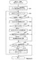
図2は、実施の形態1に係るデジタル放送受信装置1のスキャン制御部25のチャンネルスキャン時の動作を示すフローチャートである。図2に示されるように、デジタル放送受信装置1は、チャンネルスキャンに際し、まず、第1フェーズで放送方式Aに対して周波数帯域の全体内の全チャンネルをチャンネルスキャンし(ステップS101)、その後、第2フェーズで放送方式Bに対して特定のチャンネルをチャンネルスキャンする。その後、デジタル放送受信装置1が装備された移動体の移動に伴って受信可能なチャンネルが変わるので、デジタル放送受信装置1は、第1フェーズの放送方式Aのチャンネルに対するチャンネルスキャン(ステップS102)及び第2フェーズの放送方式Bのチャンネルに対するチャンネルスキャンを、繰り返す。 FIG. 2 is a flowchart showing an operation at the time of channel scanning of the
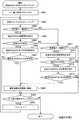
図3は、実施の形態1に係るデジタル放送受信装置1のスキャン制御部25による第1フェーズにおける放送方式Aのチャンネルに対するチャンネルスキャン処理を示すフローチャートである。図3に示されるように、第1フェーズにおけるチャンネルスキャン処理に際しては、まず、スキャン制御部25は、チューニング対象として設定されるチャンネル番号(物理チャンネル)がHであるチャンネルを、放送方式Aにおける全チャンネルの内の最小番号の物理チャンネルに設定し(ステップS201)、第2のチューナ部21にチューニングの指示を行う(ステップS202)。 FIG. 3 is a flowchart showing channel scan processing for the channel of the broadcasting system A in the first phase by the
次に、第2のチューナ部21から、受信された電波の受信レベルの判定結果がスキャン制御部25に通知される。スキャン制御部25は、受信された電波のレベル(受信電力)が、放送方式Aの放送番組を視聴するために必要な最小レベルの電力を示す閾値(電力閾値)Taよりも大きいか否かを判定し(ステップS203)、受信電力が閾値Taよりも大きいと判定された場合は、放送方式Aの復調開始を第2の復調部22に指示する(ステップS204)。この指示により、第2の復調部22は、放送方式Aのデジタル放送が存在するか否かの確認を行い、その結果をスキャン制御部25に通知する(ステップS205)。スキャン制御部25は、この通知により、放送方式Aのデジタル放送が存在すると判定した場合は、第2のデマルチプレクス部23に放送方式Aのデジタル放送のPSI/SIデータを取得する指示を通知する(ステップS206)。次に(例えば、数秒後に)、第2の復調部22は、PSI/SIデータが取得できたか否かを判定し(ステップS207)、取得できた場合には、PSI/SIデータから選局情報を抽出し、記憶部24に、検出したサービス及び物理チャンネル等をサービスリストとして登録する(ステップS208)。 Next, the
次に、スキャン制御部25は、受信チャンネルのチャンネル番号Hがチャンネルスキャン対象のチャンネルのチャンネル番号の最大値(最大番号)以下であるか否かを判定し(ステップS209)、チャンネル番号の最大値以下であれば受信チャンネルのチャンネル番号Hを1つインクリメントし(ステップS210)、処理をステップS202のチューニング処理のステップに戻す。 Next, the
一方、ステップS203において、受信電力が閾値Ta以下であると判定された場合、又は、ステップS205において放送方式Aのデジタル放送が存在しないと判定された場合は、スキャン制御部25は、受信電力が閾値(電力閾値)Tbより大きいか否かを判定する(ステップS211)。閾値Tbは、放送方式Bの放送番組を視聴するために必要な最小レベルの電力を示す閾値である。受信電力が閾値Tbよりも大きいと判定された場合は、スキャン制御部25は、受信チャンネルのチャンネル番号Hをチャンネル一時記憶部26に記憶させる。チャンネル一時記憶部26に記憶させたチャンネル番号は、第2フェーズの放送方式Bのチャンネルに対するチャンネルスキャンにおけるチューニング対象のチャンネルである。 On the other hand, if it is determined in step S203 that the received power is equal to or lower than the threshold value Ta, or if it is determined in step S205 that there is no digital broadcast of broadcasting system A, the
ステップS211において、受信電力が閾値Tb以下と判定された場合、又は、ステップS207において放送方式Aのデジタル放送のPSI/SIデータが受信できなかったと判定された場合は、処理はステップS209に進み、スキャン制御部25は、次の物理チャンネルの選局の必要性を判定する。ステップS209において、受信チャンネルのチャンネル番号Hが放送方式Aのチャンネルのチャンネル番号の最大値(最大番号)より大きいと判定された場合(ステップS209において判定NOの場合)は、全チャンネルのチャンネルスキャンが終了したと判定した場合であり、スキャン制御部25は、第1フェーズのチャンネルスキャンを終了する。 If it is determined in step S211 that the received power is equal to or lower than the threshold value Tb, or if it is determined in step S207 that the PSI / SI data of the digital broadcast of the broadcasting method A cannot be received, the process proceeds to step S209. The
図4は、実施の形態1に係るデジタル放送受信装置1のスキャン制御部25による第2フェーズにおける放送方式Bのチャンネルに対するチャンネルスキャン処理を示すフローチャートである。図4に示されるように、第2フェーズにおけるチャンネルスキャン処理に際しては、まず、放送方式Bのチャンネルに対するチャンネルスキャンを行うが、デジタル放送の帯域内の全チャンネルをスキャンするのではなく、第1フェーズでチャンネル一時記憶部26に一時記憶された物理チャンネルだけをチャンネルスキャン対象のチャンネルとする。まず、スキャン制御部25は、チャンネル一時記憶部26に一時記憶された物理チャンネルのうち、最小番号の物理チャンネルをチューニング対象とし(ステップS301)、第2のチューナ部21にチューニングの指示を行う(ステップS302)。 FIG. 4 is a flowchart showing a channel scan process for the broadcast system B channel in the second phase by the
次に、スキャン制御部25には、第2のチューナ部21から、受信された電波の受信レベルの判定結果が通知される。スキャン制御部25は、受信電力が放送方式Bの放送番組を視聴するために必要な最小レベルの電力を示す閾値Tbよりも大きいか否かを判定し(ステップS303)、受信電力が閾値Tbよりも大きいと判定された場合は、放送方式Bの復調開始を第2の復調部22に指示する(ステップS304)。この指示により、第2の復調部22は、放送方式Bが存在するか否かの確認を行い、その結果をスキャン制御部25に通知する(ステップS305)。スキャン制御部25は、この通知により放送方式Bが存在すると判定した場合は、第2のデマルチプレクス部23に放送方式BのPSI/SIデータを取得する指示を通知する(ステップS306)。その後に(例えば、数秒後に)、スキャン制御部25は、PSI/SIデータが取得できたか否かを判定し(ステップS307)、取得できた場合は、PSI/SIデータから選局情報を抽出し、記憶部24に、検出したサービス及び物理チャンネル等をサービスリストとして登録する(ステップS308)。 Next, the
そして、スキャン制御部25は、チャンネル一時記憶部26内の第1フェーズで登録された全チャンネルのチャンネルスキャンが終了したか否かを判定し(ステップS309)、終了していなければ受信チャンネルのチャンネル番号Hを、チャンネル一時記憶部26内の第1フェーズで登録された全チャンネルにおいて次に大きいチャンネル番号の物理チャンネルにし(ステップS310)、再びステップS302で次のチャンネルをチューニングする。 Then, the
ステップS303において受信電力が閾値Tb以下と判定された場合、ステップS305において放送方式Bのチャンネルが存在しなかったと判定された場合、及びステップS305において放送方式Bのチャンネルが存在しないと第2の復調部22から通知があった場合、或いは、ステップS307において放送方式BのPSI/SIデータが取得されていなかった場合は、処理はステップS309に進み、スキャン制御部25は、次の物理チャンネルのチューニングの必要性を判定する。 If it is determined in step S303 that the received power is equal to or less than the threshold value Tb, if it is determined in step S305 that there is no broadcast system B channel, and if there is no broadcast system B channel in step S305, the second demodulation is performed. If there is a notification from the
チャンネル一時記憶部26内の第1フェーズで登録された全チャンネルのチャンネルスキャンが終了したと判定された場合(ステップS309でYES)は、全チャンネルのチャンネルスキャンが終了した場合であり、スキャン制御部25は、第2フェーズのチャンネルスキャンを終了する。 When it is determined that the channel scan for all channels registered in the first phase in the channel
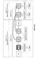
図5は、実施の形態1に係るデジタル放送受信装置1のスキャン制御部25によるチャンネルスキャン動作を示す図である。図5においては、向かって左から右に時間が進む。図5は、放送方式Aのチャンネルに対するチャンネルスキャンが第1フェーズで行われ、放送方式Bのチャンネルに対するチャンネルスキャンは第1フェーズの後の第2フェーズで実施されることを示している。 FIG. 5 is a diagram showing a channel scan operation by the
第1フェーズのチャンネルスキャンでは、例えば、チャンネル番号「13ch」から昇順に第1フェーズの放送方式Aのチャンネルに対するチャンネルスキャンが行われる。第1フェーズのチャンネルスキャンでは、チャンネル番号「64ch」までチャンネルスキャンが行われたときに、第1フェーズのチャンネルスキャンの終了条件(図3のステップS209)により第1フェーズのチャンネルスキャンが終了している。 In the channel scan of the first phase, for example, the channel scan is performed on the channel of the broadcasting system A of the first phase in ascending order from the channel number “13ch”. In the channel scan of the first phase, when the channel scan is performed up to the channel number “64ch”, the channel scan of the first phase is completed according to the channel scan end condition (step S209 in FIG. 3). Yes.
この第1フェーズの放送方式Aのチャンネルに対するチャンネルスキャンでは、図5に示すように、スキャン制御部25は、チャンネル番号「14ch」に放送方式Aを検出し、記憶部24にサービス情報を登録している。また、チャンネル番号「25ch」及び「34ch」では、電波の受信レベルが閾値Taよりも大きかったが、第2の復調部22から放送方式Aが未検出の通知を受けたため、スキャン制御部25は、受信された電波が放送方式Aではなかったと判断し、受信電力が閾値Tbよりも大きいことを確認後(図3のステップS211)、チャンネル一時記憶部26にチャンネル番号「25ch」及び「34ch」を放送方式Bの視聴可能チャンネル候補として一時記憶させる(図3のステップS212)。 In the channel scan for the channel of the broadcasting system A in the first phase, as shown in FIG. 5, the
次に、第2フェーズの放送方式Bのチャンネルに対するチャンネルスキャンでは、第1フェーズのチャンネルスキャンで、電波の受信レベルが閾値Tbよりも大きいが、この電波から生成された電気信号を復調できなかったチャンネル番号「25ch」及び「34ch」のチャンネル(放送方式Bの視聴可能チャンネル候補)のみを対象にチャンネルスキャンが行われる。そして、これらチャンネルが放送方式Bの放送波を送信している場合には、第2の復調部22で復調を行うことができ、スキャン制御部25は、選局情報を抽出し記憶部26のサービスリストに検出したサービスを登録する。 Next, in the channel scan for the channel of the broadcasting system B of the second phase, the reception level of the radio wave is larger than the threshold value Tb in the channel scan of the first phase, but the electric signal generated from this radio wave could not be demodulated. Channel scanning is performed only for channels with channel numbers “25ch” and “34ch” (broadcast system B viewable channel candidates). When these channels transmit broadcast waves of the broadcasting system B, the
以上のように、実施の形態1に係るデジタル放送受信装置1は、視聴用の第1の受信系統10は、複数の放送方式に対応した第1のチューナ部11、第1の復調部12、及び第1のデマルチプレクス部13を備え、チャンネルスキャン用の第2の受信系統20は、複数の放送方式に対応した第2のチューナ部21、第2の復調部22、及び第2のデマルチプレクス部23を備え、チャンネルスキャン用の第2の受信系統20でチャンネルスキャンを行うようにしたので、第1の受信系統10による視聴を中断することなく、チャンネルスキャンを実行することができる。 As described above, in the digital
また、実施の形態1に係るデジタル放送受信装置1は、チャンネルスキャン用の第2の受信系統20が、まず、第1フェーズで放送方式Aのチャンネルに対するチャンネルスキャンを物理チャンネルの昇順(チャンネル番号の昇順)に順に実行し、その過程で、電波の受信レベルは予め定められた閾値Taよりも大きいが、この電波による電気信号を復調できなかった物理チャンネルのチャンネル番号をチャンネル一時記憶部26に記録するようにしている。そして、その後、スキャン制御部25は、第2フェーズの放送方式Bのチャンネルに対するチャンネルスキャンにおいて、チャンネル一時記憶部26に記録されたこれらのチャンネル番号のチャンネル(放送方式Bの視聴可能チャンネル候補)のみ、すなわち、間引かれたチャンネル以外のチャンネルについて、チャンネルスキャンを行うようにした。このため、実施の形態1に係るデジタル放送受信装置1によれば、スキャン制御部25が放送方式Aと放送方式Bのそれぞれに対して、単純に全チャンネルをチャンネルスキャンする場合と比べて、最大で約1/2程度のチャンネルスキャンに要する時間の短縮効果がある。 Further, in the digital
なお、上記説明では放送方式Aのチャンネルに対するチャンネルスキャンを先に行い、その結果を利用して放送方式Bのチャンネルに対するチャンネルスキャンを行う例を示した。しかし、閾値Tbが閾値Taより小さい場合(Ta>Tbの場合)には、閾値の小さい放送方式Bを先にチャンネルスキャンし、次に、放送方式Aのチャンネルに対するチャンネルスキャンを行うことが望ましい。この場合には、図3におけるステップS203でNOと判定された場合、すなわち、受信電力が閾値よりも小さい場合には、ステップS211において受信電力は必ず閾値よりも小さくなるため、ステップS211の処理を省略することができ、その結果、チャンネルスキャンに要する時間を一層短縮することができる。 In the above description, an example is shown in which the channel scan for the broadcast system A channel is performed first, and the channel scan for the broadcast system B channel is performed using the result. However, when the threshold value Tb is smaller than the threshold value Ta (when Ta> Tb), it is desirable to perform channel scanning for the broadcasting method B having the smaller threshold value first, and then perform channel scanning for the channel of the broadcasting method A. In this case, if NO is determined in step S203 in FIG. 3, that is, if the received power is smaller than the threshold value, the received power is always smaller than the threshold value in step S211, so the process of step S211 is performed. As a result, the time required for the channel scan can be further shortened.
また、第2の復調部22における復調処理時間は、フレーム周期などに依存し、放送方式によって大きく異なる。また、各放送方式が運用するチャンネル数は、地域によって大きく異なる。そこで、事前に測定しておいた各放送方式の復調処理時間と、地域毎の運用チャンネル数をスキャン制御部25内のメモリ又はデジタル放送受信装置1内の記憶部に保持しておき、現在位置取得部又はユーザからの現在地域設定等により、スキャン制御部25は、現在位置地域を把握し、現在位置地域においてどの放送方式を先に存在確認するかを判断し動作することで、その地域における最適なスキャンシーケンスを実行し、チャンネルスキャンに要する時間を一層短縮することができる。例えば、デジタル放送受信装置1が置かれている地域で放送されている複数の放送方式の運用チャンネル数の割合の多いものを先にチャンネルスキャン対象とするように、チャンネルスキャンを実行する。このようにすることで、第2フェーズにおけるチューニング回数を減らすことができる。これは、運用チャンネル数の少ない放送方式を第1フェーズで先にチャンネルスキャンする場合に比べ、第1フェーズと第2フェーズでの合計のチューニング回数が、少なくすることができるからである。 Further, the demodulation processing time in the
また、スキャン制御部25は、第2の復調部22における復調処理時間や、第2のデマルチプレクス部23における処理時間が最も短い放送方式を第1フェーズで先にチャンネルスキャンしてもよい。この方式と、チューニング後に放送方式Aの受信確認を実施し、その結果、放送方式Aのデジタル放送が存在しなかった場合に、続いて放送方式Bの受信確認を行う方式と比べると、実施の形態1の動作のほうが、第1フェーズでの放送方式のチャンネルスキャンを早く完了させることができるので、第1フェーズで実施した放送方式のサービスリストや番組をユーザに早く表示させることができる。さらに、第1フェーズで受信確認する放送方式の運用チャンネル数が多い場合、多くのサービスが早く選局可能になるので、より効果が高い。これは、例えば、最近運用が開始され、まだ運用チャンネル数の少ないDVB−T2と、早くから運用開始されている運用チャンネル数の多いDVB−Tを両方受信可能なデジタル放送受信装置において、復調処理時間の短いDVB−Tのチャンネルスキャンを第1フェーズで実施した際に上記効果が大きい。また、上記説明においては、受信電力と閾値との比較判定は、受信電力が閾値より大きいか否かの判定「受信電力>閾値」として説明したが、受信電力が閾値以上であるか否かの判定「受信電力≧閾値」としてもよく、このことは、他の実施の形態にも当てはまる。 In addition, the
実施の形態2.
図6は、実施の形態2に係るデジタル放送受信装置2の構成を概略的に示すブロック図である。図6において、図1に示される構成要素と同一又は対応する構成要素には、図1における符号と同じ符号を付す。図6に示されるように、デジタル放送受信装置2は、複数の放送方式のデジタル放送を受信可能な視聴用の受信系統である第1の受信系統10と、複数の放送方式のデジタル放送を受信可能なチャンネルスキャン用の受信系統である第2の受信系統20aとを有する。第1の受信系統10は、第1のチューナ部11と、第1の復調部12と、第1のデマルチプレクス部13と、デコード部14と、映像音声出力部15と、選局制御部16とを有する。第2の受信系統20aは、第2のチューナ部21と、第2の復調部22と、第2のデマルチプレクス部23と、記憶部24と、スキャン制御部27とを有する。実施の形態2に係るデジタル放送受信装置2は、実施の形態1におけるチャンネル一時記憶部26を有していない点、及び、スキャン制御部27の動作が、実施の形態1に係るデジタル放送受信装置1と異なる。実施の形態1においては、第1フェーズと第2フェーズでそれぞれ異なる放送方式を対象としたチャンネルスキャンを実施したが、実施の形態2では、フェーズを分けずにチャンネルスキャン処理を実行する。実施の形態2に係るデジタル放送受信装置2は、チャンネルスキャン処理において、複数の放送方式の内の第1の放送方式及び第2の放送方式のデジタル放送の周波数帯域の全体に対するチャンネルスキャンを実行し、第1の放送方式の視聴可能チャンネルを検出して記憶部24に登録し、チャンネルスキャンの過程で、第1の放送方式の視聴可能チャンネルではないが第2の放送方式の復調処理ロジックで復調できた信号を第2の放送方式の視聴可能チャンネルとして記憶部24に登録することを特徴としている。Embodiment 2. FIG.
FIG. 6 is a block diagram schematically showing the configuration of the digital broadcast receiving apparatus 2 according to the second embodiment. 6, components that are the same as or correspond to the components shown in FIG. 1 are given the same reference numerals as those in FIG. As shown in FIG. 6, the digital broadcast receiving apparatus 2 receives a
図7は、実施の形態2に係るデジタル放送受信装置2のスキャン制御部27によるチャンネルスキャン処理を示すフローチャートである。実施の形態2においては、チャンネルスキャン処理に際し、スキャン制御部27は、受信チャンネルHとして、先ず最小番号の物理チャンネルをチューニング対象と決定し(ステップS401)、次に第2のチューナ部21にチューニングの指示を行う(ステップS402)。 FIG. 7 is a flowchart showing channel scan processing by the
次に、第2のチューナ部21から、受信された電波の受信レベルの判定結果がスキャン制御部27に通知される。スキャン制御部27は、受信電力が、放送方式Aの放送番組を視聴するために必要な最小レベルの電力を示す閾値Taよりも大きいか否かを判定し(ステップS403)、受信電力が閾値Taよりも大きいと判定された場合は、放送方式Aの復調開始を第2の復調部22に指示する(ステップS404)。この指示により、第2の復調部22は、放送方式Aのデジタル放送が存在するか否かの確認を行い、その結果をスキャン制御部27に通知する(ステップS405)。スキャン制御部27は、この通知により放送方式Aのデジタル放送が存在すると判定した場合は、第2のデマルチプレクス部23に放送方式Aのデジタル放送のPSI/SIデータを取得する指示を通知する(ステップS406)。その後に(例えば、数秒後に)、スキャン制御部27は、PSI/SIデータが取得できたか否かを判定し(ステップS407)、取得できた場合は、PSI/SIデータから選局情報を抽出し、記憶部24に、検出したサービス及び物理チャンネル等をサービスリストとして登録する(ステップS408)。 Next, the
そして、スキャン制御部27は、受信チャンネルのチャンネル番号Hがチャンネルスキャン対象のチャンネルのチャンネル番号の最大値(最大番号)以下か否かを判定し(ステップS409)、放送方式Aのチャンネルのチャンネル番号の最大値(最大番号)以上であれば、受信チャンネルのチャンネル番号Hを1つインクリメントし(ステップS410)、処理をステップS402に戻し、次のチャンネルをチューニングする。 Then, the
ステップS403で受信電力が閾値Ta以下と判定された場合、又は、ステップS405で放送方式Aが当該物理チャンネル内に存在しないと第2の復調部22から通知があった場合は、スキャン制御部27は、受信電力が閾値Tbより大きいか否かを判定する(ステップS411)。閾値Tbは、放送方式Bの放送番組を視聴するために必要な最小レベルの電力を示す閾値である。実施の形態2の動作は、この閾値Tbよりも受信電力が大きいと判定された場合の処理の点が、実施の形態1の動作と異なる。すなわち、実施の形態1では、受信チャンネルのチャンネル番号Hをチャンネル一時記憶部26に記憶させ、この記憶させたチャンネル番号を対象に、第2フェーズで放送方式Bのチャンネルに対するチャンネルスキャンを実施していた。これに対し、実施の形態2の動作では、スキャン制御部27は、続けて放送方式Bの復調開始を第2の復調部22に指示する(ステップS412)。この指示により、第2の復調部22は、放送方式Bが存在するか否かの確認を行い、その結果をスキャン制御部27に通知する。スキャン制御部27は、この通知により放送方式Bが存在すると判定した場合は(ステップS413)、第2のデマルチプレクス部23に放送方式BのPSI/SIデータを取得する指示を通知する(ステップS414)。その後に(例えば、数秒後に)、スキャン制御部27は、PSI/SIデータが取得できたか否かを判定し(ステップS415)、取得できた場合は、PSI/SIデータから選局情報を抽出し、記憶部24に検出したサービス及び物理チャンネル等をサービスリストに登録する(ステップS408)。 If it is determined in step S403 that the received power is equal to or less than the threshold Ta, or if the
そして、ステップS409及びステップS410において、スキャン制御部27は、次にチャンネルスキャンすべきチャンネルを決定する。 In step S409 and step S410, the
ステップS411で受信電力が閾値Tb以下と判定された場合、又は、ステップS413で放送方式Bが存在しなかった場合、又は、ステップS415で放送方式BのPSI/SIデータが受信できなかった場合は、スキャン制御部27は、処理をステップS409及びステップS410に進めて次にチャンネルスキャンすべきチャンネルを決定する。 If it is determined in step S411 that the received power is equal to or less than the threshold value Tb, or if broadcast method B does not exist in step S413, or if PSI / SI data of broadcast method B cannot be received in step S415 The
ステップS409でNOと判定された場合は、全チャンネルのチャンネルスキャンが終了したと判定した場合であり、スキャン制御部27は、一連のチャンネルスキャンを終了する。そして、その後、スキャン制御部27は、受信可能チャンネルの変化を検出するため再びステップS401からチャンネルスキャンを開始する。 If it is determined NO in step S409, it is determined that the channel scan for all channels has been completed, and the
以上のように、実施の形態2におけるチャンネルスキャン動作は、ある物理チャンネルをチューニングし、複数の放送波について順番に、第2のチューナ部21での信号レベル、第2の復調部22での指定放送波検出可否、第2のデマルチプレクス部23でのPSI/SIデータの受信可否を判定している。そして、チャンネルスキャン対象の全ての放送方式の受信可否を判定後、次の物理チャンネルをチューニングし、同様に、放送方式の受信可否を判定していく動作となっている。 As described above, in the channel scan operation in the second embodiment, a certain physical channel is tuned, the signal level in the
実施の形態2でのチャンネルスキャン制御方式は、第2の復調部22が復調対象とする放送方式を切り替えるための復調処理ロジックの切替時間が、第2のチューナ部21でチューニングに要する時間よりも短い場合に、効果がある。 In the channel scan control method in the second embodiment, the switching time of the demodulation processing logic for switching the broadcasting method to be demodulated by the
例えば、実施の形態1における1回の全チャンネルのチャンネルスキャンに要する時間Tscan1は、
TTUを、チューニング時間とし、
TADecを、放送方式Aの1チャンネルの復調処理時間とし、
TBDecを、放送方式Bの1チャンネルの復調処理時間とし、
NALLを、放送方式A及びBの全チャンネル数とし、
NAChを、放送方式Aの運用チャンネル数とし、
NBChを、放送方式Bの運用チャンネル数とし、
TADemを、放送方式Aの1チャンネルのデマルチプレクス処理時間とし、
TBDemを、放送方式Bの1チャンネルのデマルチプレクス処理時間とし、
TSWを、第2の復調部22の復調処理ロジックの切替時間とすると、
次式1で算出することができる。
Tscan1
={第1フェーズの時間(図2のステップS101)}
+{復調処理ロジックの切替時間(図2のステップS101からS102への切替)}
+{第2フェーズの時間(図2のステップS102)}
={(TTU×NALL)+(TADec×(NACh+NBCh))
+(TADem×NACh)}
+TSW
+{(TTU+TBDec+TBDem)×NBCh} …式1For example, the time Tscan1 required for one channel scan of all channels in
Let TTU be the tuning time,
Let TADec be the demodulation processing time for one channel of broadcasting system A,
Let TBdec be the demodulation processing time for one channel of broadcasting system B,
NALL is the number of all channels of broadcasting system A and B,
Let NACh be the number of operating channels for broadcasting system A,
Let NBCh be the number of operating channels for broadcast system B,
Let TADem be the demultiplexing processing time for one channel of broadcasting system A,
Let TBDem be the demultiplexing processing time for one channel of broadcasting system B,
IfTSW is the switching time of the demodulation processing logic of the
It can be calculated by the following
Tscan1
= {First phase time (step S101 in FIG. 2)}
+ {Demodulation processing logic switching time (switching from step S101 to S102 in FIG. 2)}
+ {Second phase time (step S102 in FIG. 2)}
= {(TTU × NALL ) + (TADec × (NACh + NBCh ))
+ (T ADem × N ACh) }
+ TSW
+ {(TTU + TBDec + TBDem ) × NBCh }
また、実施の形態2における1回の全チャンネルのチャンネルスキャンに要する時間Tscan2は、次式2で算出することができる。
Tscan2
={図7のステップS402〜S407の処理時間の合計値}
+{図7のステップS402〜S407の処理ロジックとステップS411からS415の処理ロジックの切替時間の合計値}
+{図7のステップS411〜S415の処理時間の合計値}
={(TTU×NALL)+(TADec+TADem)×NACh}
+{TSW×(NACh+NBCh)}
+(TTU+TBDec+TBDem)×NBCh} …式2Further, the timeTscan2 required for one channel scan of all channels in the second embodiment can be calculated by the following equation 2.
Tscan2
= {Total value of processing time in steps S402 to S407 in FIG. 7}
+ {Total value of switching time of processing logic of steps S402 to S407 in FIG. 7 and processing logic of steps S411 to S415}
+ {Total value of processing times of steps S411 to S415 in FIG. 7}
= {(TTU × NALL ) + (TAdec + TAdem ) × NACh }
+ {T SW × (N ACh + N BCh)}
+ (TTU + TBDec + TBDem ) × NBCh } Equation 2
ここで、Tscan2−Tscan1を算出すると、以下の式3となる。
Tscan2−Tscan1
={TSW×(NACh+NBCh−1)}−(TADec×NBch) …式3Here, when Tscan2 −Tscan1 is calculated, the following Expression 3 is obtained.
Tscan2 -Tscan1
= {T SW × (N ACh + N BCh -1)} - (T ADec × N Bch) ... Equation 3
よって、{TSW×(NACh+NBCh−1)}が、(TADec×NBch)より小さい場合には、Tscan2−Tscan1は、負の値となり、実施の形態2に係るデジタル放送受信装置2におけるチャンネルスキャンに要する時間Tscan2が実施の形態1に係るデジタル放送受信装置1におけるチャンネルスキャンに要する時間Tscan1よりも短くなる効果がある。Thus, the{T SW × (N ACh + N BCh -1)}, when(T ADec ×N Bch) smallerthan, Tscan2 -T scan1 becomes a negative value, the digital broadcasting according to the second embodimentThere is an effect that the time Tscan2 required for the channel scan in the receiving apparatus 2 is shorter than the time Tscan1 required for the channel scan in the digital
逆に、{TSW×(NACh+NBCh−1)}が、(TADec×NBch)より大きい場合には、Tscan2−Tscan1は、正の値となり、実施の形態1に係るデジタル放送受信装置1におけるチャンネルスキャンに要する時間Tscan1が実施の形態2に係るデジタル放送受信装置2におけるチャンネルスキャンに要する時間Tscan2よりも短くなる効果がある。Conversely, the{T SW × (N ACh + N BCh -1)}, is greater than(T ADec ×N Bch)is Tscan2 -T scan1 becomes a positive value, according to a first embodiment the digitalThere is an effect that the timeTscan1 required for the channel scan in the
また、実施の形態2に係るデジタル放送受信装置2においては、実施の形態1と同様に、チャンネルスキャン用の受信系統である第2の受信系統20aを視聴用の第1の受信系統10と別系統にしているので、視聴中であってもチャンネルスキャンを実行することができる。 Further, in the digital broadcast receiving apparatus 2 according to the second embodiment, as in the first embodiment, the
なお、上記説明では放送方式Aのチャンネルに対するチャンネルスキャンを先に行い、その結果を利用して放送方式Bのチャンネルに対するチャンネルスキャンを行う例を示した。しかし、閾値Tbが閾値Taより小さい場合(Ta>Tbの場合)には、閾値の小さい放送方式Bを先にチャンネルスキャンし、次に、放送方式Aのチャンネルに対するチャンネルスキャンを行うことが望ましい。この場合には、図7におけるステップS403でNOと判定された場合、すなわち、受信電力が閾値よりも小さい場合には、ステップS411において受信電力は必ず閾値よりも小さくなるため、ステップS411の処理を省略することができ、チャンネルスキャンに要する時間を一層短縮することができる。 In the above description, an example is shown in which the channel scan for the broadcast system A channel is performed first, and the channel scan for the broadcast system B channel is performed using the result. However, when the threshold value Tb is smaller than the threshold value Ta (when Ta> Tb), it is desirable to perform channel scanning for the broadcasting method B having the smaller threshold value first, and then perform channel scanning for the channel of the broadcasting method A. In this case, if NO is determined in step S403 in FIG. 7, that is, if the received power is smaller than the threshold value, the received power is always smaller than the threshold value in step S411. Therefore, the process of step S411 is performed. This can be omitted, and the time required for channel scanning can be further reduced.
実施の形態3.
図8は、実施の形態3に係るデジタル放送受信装置3の構成を概略的に示すブロック図である。図8において、図1に示される構成要素と同一又は対応する構成要素には、図1における符号と同じ符号を付す。図8に示されるように、デジタル放送受信装置3は、複数の放送方式のデジタル放送を受信可能な視聴用の受信系統である第1の受信系統10と、複数の放送方式のデジタル放送を受信可能なチャンネルスキャン用の受信系統である第2の受信系統20bとを有する。第1の受信系統10は、第1のチューナ部11と、第1の復調部12と、第1のデマルチプレクス部13と、デコード部14と、映像音声出力部15と、選局制御部16とを有する。第2の受信系統20bは、第2のチューナ部21と、第2の復調部22と、第2のデマルチプレクス部23と、記憶部24と、チャンネル一時記憶部26と、スキャン制御部28とを有する。実施の形態3に係るデジタル放送受信装置3は、スキャン制御部28の動作の点において、実施の形態1に係るデジタル放送受信装置1と異なる。実施の形態3に係るデジタル放送受信装置3は、チャンネルスキャン処理として、第1のチャンネルスキャン処理、及び、第2のチャンネルスキャン処理のいずれかを選択することを特徴としている。第1のチャンネルスキャン処理は、実施の形態1におけるチャンネルスキャン処理であり、第2のチャンネルスキャン処理は、実施の形態2におけるチャンネルスキャン処理である。Embodiment 3 FIG.
FIG. 8 is a block diagram schematically showing the configuration of the digital broadcast receiving apparatus 3 according to the third embodiment. 8, components that are the same as or correspond to the components shown in FIG. 1 are given the same reference numerals as those in FIG. As shown in FIG. 8, the digital broadcast receiving device 3 receives a
実施の形態1においてスキャン制御部25は、第2の復調部22の復調処理ロジックを各放送方式に切り替える時間及び第2のチューナ部21のチューニングに要する時間をそれぞれ事前に計測し、保持しておく。さらに、地域毎にその地域での放送方式Aの運用チャンネル数と放送方式Bの運用チャンネル数のデータを保持しておく。そして、チャンネルスキャンの実施前に、現在位置情報を取得するための位置情報取得部33からの位置情報、又は、ユーザ操作部34から入力された地域設定など地域を特定する情報から、スキャン制御部25は、地域を把握し、式3の計算を行い、その結果、式3の算出結果が正の値であるならば、実施の形態1に従うスキャン制御方式によるチャンネルスキャンを採用し、式3の算出結果が負の値であるならば、実施の形態2に従うスキャン制御方式によるチャンネルスキャンを採用するように、切り替えてもよい。 In the first embodiment, the
このようにすることで、移動先の地域によって受信対象となる放送方式の運用チャンネル数が異なる場合に、各地域における最適なチャンネルスキャンシーケンスを実施でき、チャンネルスキャンに要する時間を最短にすることができる。また、地域毎にその地域での放送方式Aの運用チャンネル数と放送方式Bの運用チャンネル数のデータを保持しておくことで、例えば、最近運用が開始されたDVB−T2は、地域によっては、まだ運用されている所もある。そのような場合、は、DVB−Tだけのチャンネルスキャンを実行するようにスキャン制御部28を動作させることができる。 In this way, when the number of operating channels of the broadcasting system to be received differs depending on the destination area, the optimum channel scan sequence in each area can be performed, and the time required for channel scanning can be minimized. it can. In addition, by storing data on the number of operating channels for broadcasting system A and the operating channel for broadcasting system B in each area, for example, DVB-T2 that has recently started operating may be different depending on the area. Some are still in operation. In such a case, the
また、実施の形態3に係るデジタル放送受信装置3においては、実施の形態1と同様に、チャンネルスキャン系統を視聴系統と別系統にしているので視聴中でもチャンネルスキャンを実行することができる。 In the digital broadcast receiving apparatus 3 according to the third embodiment, as in the first embodiment, since the channel scan system is separate from the viewing system, the channel scan can be executed even during viewing.
実施の形態4.
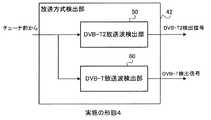
図9は、実施の形態4に係るデジタル放送受信装置4の構成を概略的に示すブロック図である。図9において、図1に示される構成要素と同一又は対応する構成要素には、図1における符号と同じ符号を付す。図9に示されるように、デジタル放送受信装置4は、複数の放送方式のデジタル放送を受信可能な視聴用の受信系統である第1の受信系統10と、複数の放送方式のデジタル放送を受信可能なチャンネルスキャン用の受信系統である第2の受信系統20cとを有する。第1の受信系統10は、第1のチューナ部11と、第1の復調部12と、第1のデマルチプレクス部13と、デコード部14と、映像音声出力部15と、選局制御部16とを有する。第2の受信系統20cは、第2のチューナ部21と、第2の復調部40と、第2のデマルチプレクス部23と、記憶部24と、チャンネル一時記憶部26と、スキャン制御部29とを有する。実施の形態4に係るデジタル放送受信装置4は第2の復調部40の内部構成及びスキャン制御部29の動作の点において、図1に示される実施の形態1に係るデジタル放送受信装置1と異なる。実施の形態4に係るデジタル放送受信装置4は、複数の放送方式の内の第1の放送方式及び第2の放送方式のデジタル放送の周波数帯域の全体に対するチャンネルスキャン処理を実行する過程において、チューナ部21が対象チャンネルをチューニングした後に、スキャン制御部29が第1の放送方式の放送波の存在確認を行い、第1の放送方式の放送波が存在すると判定されたときには、復調部40による第1の放送方式の復調処理及びデマルチプレクス部23によるデータ取得処理を行い、第1の放送方式の放送波が存在しないと判定されたときには、第2の放送方式の放送波の存在確認を行わないことを特徴としている。チャンネルスキャン処理の詳細は、後述する。Embodiment 4 FIG.
FIG. 9 is a block diagram schematically showing the configuration of the digital broadcast receiving apparatus 4 according to the fourth embodiment. 9, components that are the same as or correspond to the components shown in FIG. 1 are given the same reference numerals as those in FIG. As shown in FIG. 9, the digital broadcast receiving device 4 receives a
図10は、実施の形態4に係るデジタル放送受信装置4の第2の復調部40の構成を概略的に示すブロック図である。図10に示されるように、第2の復調部40は、TS(トランスポートストリーム)復調処理部41と、放送方式検出部42とを有する。実施の形態1及び2における第2の復調部22は、復調処理の結果、複数のフレームの同期が確立するとTSを出力すると共に、フレーム同期が確立したことにより、指定された放送方式が検出できたか否かをスキャン制御部25に通知する。これに対し、実施の形態4においては、TS復調を行うTS復調処理部41とは別に放送方式検出部42を備えている。これは、フレーム同期が確立する前に素早く放送方式を検出するためであり、特に、DVB−T2とDVB−Tとを受信対象とする場合に、適した構成である。 FIG. 10 is a block diagram schematically showing the configuration of the
図11(a)及び(b)は、DVB−T2フレーム構造、並びに、DVB−T2で運用される伝送モード及びガードインターバルを示す図である。図11(a)に示されるように、DVB−T2フレームは、1つのP1シンボルと、複数のP2シンボルと、複数のDataシンボルとから構成され、DVB−T2フレームのフレーム長は、最大250msである。DVB−T2フレームは、250ms周期で連続的にチューナ部(第1,第2のチューナ部11,21)から出力される。DVB−T2のTSは、Dataシンボル内に格納されている。このTSを復調するには、復調処理に必要となるパラメータがP2シンボルに含まれているので、Dataシンボルより先にP2シンボルを復調する必要がある。さらに、P2シンボルの復調のためには、P1シンボル内に含まれるP2シンボルのFFT(Fast Fourier Transform)サイズ等の情報を取得する必要がある。そのため、TSを復調するためには、まず、P1シンボルを復調する必要がある。DVB−T2放送方式では、P1シンボルに必要なパラメータは、事前に規定されており、まず、P1シンボルから復調することが規定されている。 FIGS. 11A and 11B are diagrams showing a DVB-T2 frame structure, a transmission mode and a guard interval operated in DVB-T2. As shown in FIG. 11A, the DVB-T2 frame is composed of one P1 symbol, a plurality of P2 symbols, and a plurality of Data symbols, and the DVB-T2 frame has a maximum frame length of 250 ms. is there. The DVB-T2 frame is continuously output from the tuner unit (first and
図11(a)に示されるように、P1シンボル、P2シンボル、及びDataシンボルは、それぞれ有効シンボルとガードインターバルから構成されるが、P1シンボルの構造は、他と異なる。P1シンボルにおいては、有効シンボルの前半部分とその直前のガードインターバルは、同一データとなっている。また、有効シンボルの後半部分とその直後のガードインターバルは、同一データとなっている。一方、P2シンボル及びDataシンボルにおいては、有効シンボルの最後の部分が、その有効シンボルの直前のガードインターバル部分と同じデータとなっている。 As shown in FIG. 11A, the P1 symbol, the P2 symbol, and the Data symbol are each composed of a valid symbol and a guard interval, but the structure of the P1 symbol is different from the others. In the P1 symbol, the first half of the effective symbol and the guard interval immediately before it are the same data. Further, the latter half of the effective symbol and the guard interval immediately after that are the same data. On the other hand, in the P2 symbol and the Data symbol, the last part of the effective symbol is the same data as the guard interval part immediately before the effective symbol.
図11(a)に示される有効シンボル長は、伝送モードが示すビット長になっており、FFTサイズと等しい値である。DVB−T2で使用される伝送モード(FFTサイズ)とガードインターバル値(ガードインターバル長と有効シンボル長との比、すなわち、ガードインターバル長/有効シンボル長)の組み合わせを図11(b)に示す。 The effective symbol length shown in FIG. 11A is the bit length indicated by the transmission mode, and is equal to the FFT size. FIG. 11B shows combinations of transmission modes (FFT size) and guard interval values (ratio between guard interval length and effective symbol length, that is, guard interval length / effective symbol length) used in DVB-T2.
図12(a)及び(b)は、DVB−Tフレーム構造、並びに、DVB−Tで運用される伝送モード及びガードインターバルを示す図である。図12(a)に示されるように、DVB−Tのフレームは、最大60msとなっており、60ms周期でDVB−Tのフレームが連続的にチューナ部より出力される。フレームは、シンボルから構成されており、フレームは、ガードインターバルと有効シンボルとから構成され、DVB−Tのシンボル構成は、DVB−T2のDataシンボルの構成と同一の構成である。すなわち、有効シンボルの最後のデータが、その有効シンボル直前のガードインターバルに格納されている。また、有効シンボル長は、伝送モードが示すサイズとなっている。ただし、DVB−Tで使用される伝送モードとガードインターバルの組み合わせは、図12(b)に記載しているように、DVB−T2で使用するこれらパラメータの組み合わせの一部のパラメータとなっている。 12A and 12B are diagrams showing a DVB-T frame structure, a transmission mode and a guard interval operated in DVB-T. As shown in FIG. 12A, the DVB-T frame has a maximum of 60 ms, and the DVB-T frame is continuously output from the tuner unit at a cycle of 60 ms. The frame is composed of symbols, the frame is composed of guard intervals and valid symbols, and the DVB-T symbol configuration is the same as the DVB-T2 Data symbol configuration. That is, the last data of the effective symbol is stored in the guard interval immediately before the effective symbol. The effective symbol length is the size indicated by the transmission mode. However, the combination of the transmission mode and guard interval used in DVB-T is a partial parameter of the combination of these parameters used in DVB-T2, as shown in FIG. .
図13は、実施の形態4に係るデジタル放送受信装置4の第2の復調部40内の放送方式検出部42の構成を概略的に示すブロック図である。図13に示されるように、放送方式検出部42は、DVB−T2放送波検出部50と、DVB−T放送波検出部60とを有している。スキャン制御部29からの指示により、DVB−T2放送波検出部50及びDVB−T放送波検出部60は、第2のチューナ部21から入力されるデジタル信号に格納される各放送波の検出を開始する。そして、DVB−T2放送波検出部50は、DVB−T2検出信号で、DVB−T放送波検出部60は、DVB−T検出信号で、それぞれの放送波検出結果をスキャン制御部29に通知する。 FIG. 13 is a block diagram schematically showing a configuration of the broadcast
図14は、実施の形態4に係るデジタル放送受信装置4のDVB−T2放送波検出部50の構成を示すブロック図である。図14に示されるように、DVB−T2放送波検出部50は、32k遅延回路501、16k遅延回路502、8k遅延回路503、4k遅延回路504、2k遅延回路505、1k遅延回路506、ガードインターバル比検出回路511、ガードインターバル比検出回路512、ガードインターバル比検出回路513、ガードインターバル比検出回路514、ガードインターバル比検出回路515、ガードインターバル比検出回路516、かけ算回路521、かけ算回路522、かけ算回路523、かけ算回路524、かけ算回路525、かけ算回路526、及び論理和ロジック531を有している。32k遅延回路501は、第2のチューナ部21からのデジタル信号を32kbit遅延する回路である。同様に、16k遅延回路502、8k遅延回路503、4k遅延回路504、2k遅延回路505、1k遅延回路506は、それぞれ第2のチューナ部21からのデジタル信号を16kbit、8kbit、4kbit、2kbit、1kbit遅延する回路である。かけ算回路521、かけ算回路522、かけ算回路523、かけ算回路524、かけ算回路525、及びかけ算回路526は、これらの遅延回路の各出力と元の第2のチューナ部21からのデジタル信号との積をとる回路であり、それら出力が各ガードインターバル比検出回路511,512,513,514,515,516にそれぞれ入力される。各ガードインターバル比検出回路511,512,513,514,515,516では、ガードインターバル長及び有効シンボル長を検出し、ガードインターバル比を求める。ガードインターバル比検出回路511,512,513,514,515,516は、求められた比が32k、16k、8k、4k、2k、1kの各伝送モードに対してDVB−T2で運用される値であれば値‘1’を出力する。ガードインターバル比検出回路511,512,513,514,515,516から出力され論理和ロジック531を経由し、DVB−T2放送波検出信号が出力される。なお、かけ算回路521,522,523,524,525,526は、回路規模を小さくするために、2入力の一致を検出する排他的論理回路に置き換えることが可能である。 FIG. 14 is a block diagram illustrating a configuration of the DVB-T2 broadcast
図15は、実施の形態4に係るデジタル放送受信装置4のDVB−T放送波検出部60の構成を示すブロック図である。図15に示されるように、DVB−T放送波検出部60は、8k遅延回路601、2k遅延回路602、ガードインターバル比検出回路611、ガードインターバル比検出回路612、かけ算回路621、かけ算回路622、及び論理和ロジック631を有する。8k遅延回路601は、第2のチューナ部21からのデジタル信号を4kbit遅延する回路である。同様に、2k遅延回路602は、第2のチューナ部21からのデジタル信号を2kbit遅延する回路である。かけ算回路621及び622は、これらの遅延回路の各出力と元のチューナ部21からのデジタル信号との積をとる回路である。かけ算回路621及び622からの出力が各ガードインターバル比検出回路611,612にそれぞれ入力される。各ガードインターバル比検出回路611,612では、ガードインターバル長及び有効シンボル長を検出し、ガードインターバル比を求める。この比が8k及び2kの各伝送モードに対してDVB−Tで運用される値であれば値‘1’を出力する。この信号が各ガードインターバル比検出回路から出力され論理和ロジック631を経由しDVB−T放送波検出信号として出力される。なお、かけ算回路621、622は、回路規模を小さくするために、2入力の一致を検出する排他的論理回路に置き換えることが可能である。 FIG. 15 is a block diagram illustrating a configuration of the DVB-T broadcast
図16は、実施の形態4に係るデジタル放送受信装置のDVB−T2放送波検出部50及びDVB−T放送波検出部60の動作を示す図である。図16は、横軸を時間とし、上段は、第2のチューナ部21からDVB−T2のDataシンボル又はDVB−Tのシンボルが入力されている様子を示している。図16の中段は、各遅延回路501〜506の出力信号のうち、入力された信号のFFTサイズと一致するbit分の遅延を行う回路の出力信号を示している。図16の下段は、その出力をかけ算回路521〜526、或いは、排他的論理和回路(かけ算回路521〜526の代わりに設けられた場合)に入力した際の出力を模式的に図示している。第2のチューナ部21からのデジタル入力信号は、図16に示されるように、各シンボル内にガードインターバルと有効シンボルが含まれており、図16の斜線部が示す有効シンボルの最後のデータとガードインターバルが同じデータとなっている。各遅延回路501〜506は、規格で規定された、運用される各FFTサイズ分を遅延するので、図16の中段に示すように、各FFTサイズ分が遅延される。かけ算回路521〜526、或いは、排他的論理和回路(かけ算回路521〜526の代わりに設けられた場合)の出力は、第2のチューナ部21からの入力信号における有効シンボルの最後の部分と、遅延回路501〜506で遅延された信号におけるガードインターバルの部分が同じデータで一致するので、図16の下段のように、かけ算回路521〜526、或いは、排他的論理和回路(かけ算回路521〜526の代わりに設けられた場合)521〜526、或いは、排他的論理回路531の出力信号のピークの出現周期は、一定の一致周期Tになる。一方、入力された信号のFFTサイズと一致しないbit分の遅延を行う回路の出力信号は、図示していないがその場合は、かけ算回路521日から526のピークの周期、或いは、排他的論理和回路での2入力の一致検出ポイントを示す‘1’の出現周期は、図の下段の一致周期Tのように一定ではない。 FIG. 16 is a diagram illustrating operations of the DVB-T2 broadcast
図16の下段の信号がガードインターバル比検出回路511〜516に入力される。ガードインターバル比検出回路では、一致周期内におけるデータ数N1pをカウントする。また、一致期間のデータ数をカウントすることでガードインターバル長LGIを求める。これらから伝送モード(FFTサイズ)SFFTを以下の式4にて求める。
SFFT=N1p−LGI 式4
さらに、ガードインターバル比RGIを以下の式5で求める。
RGI=LGI/SFFT 式5The lower signal in FIG. 16 is input to the guard interval
SFFT = N1p −LGI Equation 4
Further, the guard interval ratio RGI is obtained by the following formula 5.
RGI = LGI / SFFT formula 5
DVB−T2放送波検出部50の場合は、次に、式4及び式5で求めた伝送モード(FFTサイズ)SFFT、ガードインターバル比RGIの組み合わせが、図11(b)に示すDVB−T2伝送モード−ガードインターバルの組み合わせ表に存在するかを確認し、存在した場合は、ガードインターバル比検出回路からDVB−T2検出を示す信号出力を出力する。In the case of the DVB-T2 broadcast
DVB−T放送波検出部60の場合は、次に、式4及び式5で求めた伝送モード(FFTサイズ)SFFT、ガードインターバル比RGIの組み合わせが、図12(b)に示すDVB−T伝送モード−ガードインターバルの組み合わせ表に存在するかを確認し、存在した場合は、ガードインターバル比検出回路からDVB−T検出を示す信号出力を出力する。In the case of the DVB-T broadcast
前述したようにDVB−T2で運用される伝送モードとガードインターバルの組み合わせは、DVB−Tで運用される伝送モードとガードインターバルの組み合わせを含んでいる。第2の復調部40を以上のような、FFTサイズとガードインターバルから放送方式を特定する回路で構成し、この回路の出力信号にて、上記の第2の復調部40からDVB−T2が存在しないということがわかった場合、DVB−Tで運用される伝送モード、ガードインターバルではないということになりDVB−Tの受信確認処理を省略することができる。 As described above, the combination of the transmission mode and guard interval operated in DVB-T2 includes the combination of the transmission mode and guard interval operated in DVB-T. The
図17は、実施の形態4に係るデジタル放送受信装置4のスキャン制御部29によるチャンネルスキャン処理を示すフローチャートである。実施の形態4に係るスキャン制御部29は、以上のような第2の復調部40を用いて、DVB−T2とDVB−Tのチャンネルスキャンを行う。図17において放送方式Aは、DVB−T2、放送方式Bは、DVB−Tに対応している。すなわち、放送方式Aで運用される伝送モードとガードインターバルの組み合わせは、放送方式Bで運用される伝送モードとガードインターバルの組み合わせを含んでいる。 FIG. 17 is a flowchart showing channel scan processing by the
図17に示されるように、スキャン制御部29は、まず、ステップS501で、最小番号の物理チャンネルをチューニング対象のチャンネルHとし、ステップS502で第2のチューナ部21にチューニングの指示を行う。次に、スキャン制御部29には、第2のチューナ部21から、受信された電波の受信レベルの判定結果が通知される。その結果、受信電力が、放送方式Aの放送番組を視聴するために必要となるレベルの閾値Taよりも低く、且つ、放送方式Bの放送番組を視聴するために必要となるレベルの閾値Tbよりも低い場合は、ステップS503で判定がYESとなり、そのチャンネルは、受信可能なレベルではないため、次の物理チャンネルをチューニングするため、処理はステップS509に進む。ステップS503でNOと判定された場合は、スキャン制御部29は、放送方式Aの復調開始を第2の復調部40に指示する(ステップS504)。この指示により第2の復調部40は、放送方式Aのデジタル放送が存在するか否かの確認を行い、その結果をスキャン制御部29に通知する。スキャン制御部29は、この通知により放送方式Aのデジタル放送が存在すると判定した場合は(ステップS505のYES)、第2のデマルチプレクス部23に放送方式Aのデジタル放送のPSI/SIデータを取得する指示を通知する(ステップS506)。その後に(例えば、数秒後に)、スキャン制御部29は、PSI/SIデータが取得できたか否かを判定し(ステップS507)、取得できた場合は、PSI/SIデータから選局情報を抽出し、検出したサービス及び物理チャンネル等を記憶部24のサービスリストに登録する(ステップS508)。 As shown in FIG. 17, the
そして、スキャン制御部29は、受信チャンネルのチャンネル番号Hがチャンネルスキャン対象のチャンネルのチャンネル番号の最大値(最大番号)未満か否かを判定し(ステップS509)、最大値(最大番号)未満であれば受信チャンネルのチャンネル番号Hを1つインクリメントし(ステップS510)、再びステップS502で次のチャンネルをチューニングする。 Then, the
スキャン制御部29は、ステップS505で放送方式Aのデジタル放送が存在しないとの通知を受信した場合は、放送方式Bで運用される伝送モード、ガードインターバルを用いた受信データでもなかったということになるので、放送方式Bの受信確認処理を省くことができる。このため、スキャン制御部29は、処理をステップS509、ステップS510へ進め、次にチューニングすべき物理チャンネルを取得し、ステップS502で次の物理チャンネルのチューニングを行う。 If the
スキャン制御部29は、ステップS507で放送方式Aのデジタル放送のPSI/SIデータが取得できなかった場合は、放送方式Bである可能性があるため、ステップS511で放送方式Bの復調開始を第2の復調部40に指示する。この指示により、第2の復調部40は、放送方式Bが存在するか否かの確認を行い、その結果をスキャン制御部29に通知する。スキャン制御部29は、この通知により放送方式Bが存在すると判定した場合は(ステップS512のYES)、第2のデマルチプレクス部23に放送方式BのPSI/SIデータを取得する指示を通知する(ステップS513)。その後に(例えば、数秒後に)、スキャン制御部29は、放送方式BのPSI/SIデータが取得できたか否かを判定し(ステップS514)、取得できた場合は、PSI/SIデータから選局情報を抽出し、検出したサービス及び物理チャンネル等を記憶部24にサービスリストとして登録する(ステップS508)。そして、スキャン制御部29は、処理をステップS509、ステップS510へ進め、次のチャンネルスキャンすべきチャンネルを取得する。 If the PSI / SI data of the digital broadcasting of broadcasting system A cannot be acquired in step S507, the
スキャン制御部29は、ステップS512で放送方式Bが存在しないと通知を受信した場合、又は、ステップS514で放送方式BのPSI/SIデータが受信できなかった場合は、処理をステップS509及びステップS510に進め、次にチャンネルスキャンすべきチャンネルを取得する。 If the
ステップS509でNOと判定された場合は、全チャンネルのチャンネルスキャンが終了したと判定した場合であり、スキャン制御部29は、一連のチャンネルスキャンを終了する。そして、その後、スキャン制御部29は、受信可能チャンネルの変化を検出するため、再びステップS501からチャンネルスキャンを開始する。 If it is determined NO in step S509, it is determined that channel scanning for all channels has been completed, and the
以上のように、実施の形態4におけるチャンネルスキャン動作は、チャンネルスキャン系統を視聴系統とは別に備えているため視聴中でもチャンネルスキャンを実行することができる。 As described above, since the channel scan operation in the fourth embodiment includes the channel scan system separately from the viewing system, the channel scan can be executed even during viewing.
実施の形態4における第2の復調部40は、放送方式検出部42を備え、その中のDVB−T2放送波検出部50を図14に示される回路構成にし、DVB−T2のデータシンボルに対して、DVB−T2で運用される32k、16k、8k、4k、2k、1kの各伝送モードの信号が伝送されたことをそれぞれ検出する伝送モード検出回路500を遅延回路501〜506とかけ算回路521〜526又は排他的論理和回路とを並列に備えたので、伝送モードを短時間で検出することができる。 The
さらに、各伝送モード検出回路の出力を、各ガードインターバル比検出回路に入力したので、受信したTSの伝送モードとガードインターバルの組み合わせを短時間で検出することができる。従来、TSの復調過程でP1シンボル、P2シンボル、Dataシンボルの順に復調し、さらに、2〜3個のDVB−T2フレームを受信し、フレーム同期を確立してDVB−T2の復調されたTSが出力されていた。この時点でDVB−T2検出完了の通知がされる復調部と比較すると、DVB−T2フレームは、最大250ms周期であるため、フレーム同期確立の検出完了となる500ms〜750msもの期間、DVB−T2の存在検出結果を待つことになっていた。これに対し、実施の形態4における第2の復調部40では、1フレーム期間待つだけでよいので、短時間に放送方式の存在検出が可能となる。 Furthermore, since the output of each transmission mode detection circuit is input to each guard interval ratio detection circuit, the combination of the transmission mode and guard interval of the received TS can be detected in a short time. Conventionally, P1 symbol, P2 symbol, and Data symbol are demodulated in this order in the process of demodulating TS, and further, two to three DVB-T2 frames are received, frame synchronization is established, and demodulated TS of DVB-T2 is demodulated. It was output. Compared to the demodulator that is notified of the completion of DVB-T2 detection at this point, the DVB-T2 frame has a maximum period of 250 ms. Therefore, the period of 500 ms to 750 ms during which frame synchronization establishment is completed is detected. Waiting for the presence detection result. On the other hand, in the
また、実施の形態4における第2の復調部40は、TSを復調し、後段の第2のデマルチプレクス部23にTSを出力するTS復調処理部41とは別に、放送方式検出部42を備えたので、図17のステップS505及びステップS512での各放送方式存在確認後、TS復調処理を開始する必要がないのでTSが復調されるまでの時間が短縮される。 In addition, the
以上のような復調処理により、実施の形態4におけるチャンネルスキャン動作は、短時間で行うことができる。 Through the demodulation processing as described above, the channel scan operation in Embodiment 4 can be performed in a short time.
また、実施の形態4におけるスキャン制御部29は、放送方式Bで運用される伝送モード、ガードインターバルのパラメータの組み合わせを含む、パラメータで運用される放送方式Aから先に放送方式検出確認を、第2の復調部40に指示するので、その結果が、放送方式Aで無かった場合に、放送方式Bの存在検出処理が不要となりチャンネルスキャンに要する時間を短縮することができる。 In addition, the
実施の形態5.
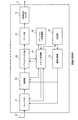
図18は、実施の形態5に係るデジタル放送受信装置5の構成を概略的に示すブロック図である。図18において、図9に示される構成要素と同一又は対応する構成要素には、図9における符号と同じ符号を付す。図18に示されるように、デジタル放送受信装置5は、複数の放送方式のデジタル放送を受信可能な視聴用の受信系統である第1の受信系統10と、複数の放送方式のデジタル放送を受信可能なチャンネルスキャン用の受信系統である第2の受信系統20dとを有する。第1の受信系統10は、第1のチューナ部11と、第1の復調部12と、第1のデマルチプレクス部13と、デコード部14と、映像音声出力部15と、選局制御部16とを有する。第2の受信系統20dは、第2のチューナ部21と、第2の復調部40と、第2のデマルチプレクス部23と、記憶部24と、チャンネル一時記憶部26と、メモリ45aを有するスキャン制御部45とを有する。実施の形態5に係るデジタル放送受信装置5は、スキャン制御部45のメモリ45aに、地域毎にDVB−T2の運用チャンネル数とDVB−Tの運用チャンネル数を記載した放送方式運用割合テーブルを記憶しており、これを参照しチャンネルスキャン時のチューニングの後に、いずれの放送方式から先に放送波存在確認を行うべきか否かを判定し、その判定結果に基づく順にチャンネルスキャンを行う点が、実施の形態4に係るデジタル放送受信装置4と異なる。実施の形態5においては、スキャン制御部45は、複数の放送方式の運用チャンネル数を含む情報を記憶するメモリ45aを有し、複数の放送方式の内の運用チャンネル数の多い放送方式を第1の放送方式として先に放送波存在確認を行うことを特徴としている。Embodiment 5. FIG.
FIG. 18 is a block diagram schematically showing the configuration of the digital broadcast receiving apparatus 5 according to the fifth embodiment. 18, components that are the same as or correspond to the components shown in FIG. 9 are given the same reference numerals as those in FIG. As shown in FIG. 18, the digital broadcast receiving apparatus 5 receives a
DVB−T2の運用チャンネル数とDVB−Tの運用チャンネル数は、地域毎に異なる。DVB−T2は、最近運用が始まったばかりであり、現時点では、DVB−T2よりもDVB−Tのチャンネルが圧倒的に多いが、今後DVB−T2の運用チャンネルが多くなっていくことが見込まれる。 The number of operating channels for DVB-T2 and the number of operating channels for DVB-T differ from region to region. DVB-T2 has just started operation. At present, there are overwhelmingly more DVB-T channels than DVB-T2, but it is expected that there will be more DVB-T2 operation channels in the future.
一方、DVB−T2の放送方式判定時間は、実施の形態3における第2の復調部22に示したように、例えば、放送方式判定に要する時間は、最大1フレーム時間(250ms)である。一方、DVB−Tの放送方式判定に要する時間は、図12(a)に示すように、DVB−Tフレームが最大60msであるため、最大60msである。 On the other hand, as shown in the
そのため、DVB−Tの運用チャンネル数がDVB−T2のそれより圧倒的に多い場合は、検出時間の短いDVB−Tから先に放送方式判定を行う。これにより、全チャンネルスキャンに要する時間を短くすることができる。DVB−T及びDVB−T2の運用チャンネル数は、ユーザ操作部からの入力によって、又は、前回のチャンネルスキャン結果から、運用チャンネル数を、スキャン制御部45内のメモリ又は記憶部に保持させておく。 Therefore, when the number of operating channels of DVB-T is overwhelmingly larger than that of DVB-T2, the broadcast system determination is performed first from DVB-T having a short detection time. Thereby, the time required for all channel scanning can be shortened. The number of operating channels of DVB-T and DVB-T2 is retained in the memory or storage unit in the
逆に、DVB−T2の運用チャンネルが圧倒的に多い場合は、DVB−T2から先に放送方式判定を行うようにする。この場合、ある物理チャンネルがDVB−T2でなかったときには、実施の形態3で説明したように、この物理チャンネルはDVB−Tでもないため、放送方式判定時間は250msである。 Conversely, when the DVB-T2 operating channel is overwhelmingly large, the broadcast system determination is performed first after DVB-T2. In this case, when a certain physical channel is not DVB-T2, as described in the third embodiment, since this physical channel is not DVB-T, the broadcast method determination time is 250 ms.
以上に説明したように、実施の形態5においては、各放送方式の運用チャンネル数の割合に応じて、いずれの放送方式を先に存在判定するかを判断しチャンネルスキャンを行うことで、各地域に移動した際にそれぞれの地域に最適なチャンネルスキャンを実行できチャンネルスキャンに要する時間の短縮を図ることができる。 As described above, in the fifth embodiment, according to the ratio of the number of operating channels of each broadcasting method, it is determined which broadcasting method is first determined and channel scanning is performed, so that each region When moving to the location, the optimum channel scan for each area can be executed, and the time required for the channel scan can be shortened.
実施の形態6.
図19は、実施の形態6に係るデジタル放送受信装置6の構成を概略的に示すブロック図である。図19において、図1に示される構成要素と同一又は対応する構成要素には、図1における符号と同じ符号を付す。図19に示されるように、デジタル放送受信装置6は、アンテナ32からの放送信号を受信するチューナ部21と、復調部22と、デマルチプレクス部23と、記憶部24と、スキャン制御部25と、チャンネル一時記憶部26と、デコード部14と、映像音声出力部15と、選局制御部16とを有する。実施の形態6に係るデジタル放送受信装置6は、1つの受信系統を有する点において、図1に示される実施の形態1に係るデジタル放送受信装置1と異なる。Embodiment 6 FIG.
FIG. 19 is a block diagram schematically showing the configuration of the digital broadcast receiving device 6 according to the sixth embodiment. 19, components that are the same as or correspond to the components shown in FIG. 1 are given the same reference numerals as those in FIG. As shown in FIG. 19, the digital broadcast receiving apparatus 6 includes a
実施の形態6に係るデジタル放送受信装置6におけるチャンネルスキャン処理は、実施の形態1におけるチャンネルスキャン処理と同じである。しかし、実施の形態6に係るデジタル放送受信装置6は、1つの受信系統しか有しておらず、視聴用の受信系統とチャンネルスキャン用の受信系統は共通であるので、チャンネルスキャンの実施中は、放送番組を視聴することはできない。しかしながら、実施の形態6によれば、構成の簡素化による製品コストの低減を実現できる。 The channel scan process in the digital broadcast receiving apparatus 6 according to the sixth embodiment is the same as the channel scan process in the first embodiment. However, since the digital broadcast receiving apparatus 6 according to Embodiment 6 has only one receiving system, and the viewing receiving system and the channel scanning receiving system are common, the channel scanning is being performed. You cannot watch broadcast programs. However, according to the sixth embodiment, the product cost can be reduced by simplifying the configuration.
なお、実施の形態6と同様の構成を採用することによって、実施の形態2から5に係るデジタル放送受信装置の受信系統を1系統にする、すなわち、視聴用の第1の受信系統とチャンネルスキャン用の第2の受信系統を共通の1つの受信系統にすることもできる。この場合にも、構成の簡素化による製品コストの低減を実現できる。 By adopting the same configuration as in the sixth embodiment, the receiving system of the digital broadcast receiving apparatus according to the second to fifth embodiments is reduced to one system, that is, the first receiving system for viewing and the channel scan. The common second receiving system can be used as the second receiving system. Also in this case, the product cost can be reduced by the simplification of the configuration.
本発明は、例えば、自動車又は列車などのような移動体に搭載されるデジタル放送受信装置に適用可能である。また、本発明は、デジタルテレビ放送の受信装置だけでなく、デジタルラジオ放送の受信装置にも適用可能である。さらに、本発明は、家庭用のデジタル放送受信装置だけでなく、スマートフォン及びタブレット端末などのような携帯情報端末用のデジタル放送受信装置にも適用可能である。 The present invention can be applied to a digital broadcast receiving device mounted on a moving body such as an automobile or a train. Further, the present invention can be applied not only to a digital television broadcast receiver but also to a digital radio broadcast receiver. Furthermore, the present invention can be applied not only to home digital broadcast receivers but also to digital broadcast receivers for portable information terminals such as smartphones and tablet terminals.
1,2,3,4,5,6 デジタル放送受信装置、 10 第1の受信系統、 11 第1のチューナ部、 12 第1の復調部、 13 第1のデマルチプレクス部、 14 デコード部、 15 映像音声出力部、 16 選局制御部、 20,20a,20b,20c,20d 第2の受信系統、 21 第2のチューナ部、 22,40 第2の復調部、 23 第2のデマルチプレクス部、 24 記憶部、 25,27,28,29,45 スキャン制御部、 26 チャンネル一時記憶部、 31 第1のアンテナ、 32 第2のアンテナ、 33 位置情報取得部、 34 ユーザ操作部、 41 TS復調処理部、 42 放送方式検出部、 50 DVB−T2放送波検出部、 60 DVB−T放送波検出部、 501 32k遅延回路、 502 16k遅延回路、 503 8k遅延回路、 504 4k遅延回路、 505 2k遅延回路、 506 1k遅延回路、 511〜516 ガードインターバル比検出回路、 521〜526 かけ算回路、 531 排他論理和回路、 601 8k遅延回路、 602 2k遅延回路、 611〜612 ガードインターバル比検出回路、 621〜622 かけ算回路。 1, 2, 3, 4, 5, 6 Digital broadcast receiving apparatus, 10 1st receiving system, 11 1st tuner section, 12 1st demodulating section, 13 1st demultiplexing section, 14 decoding section, 15 video / audio output unit, 16 channel selection control unit, 20, 20a, 20b, 20c, 20d second reception system, 21 second tuner unit, 22, 40 second demodulation unit, 23 second demultiplexing Unit, 24 storage unit, 25, 27, 28, 29, 45 scan control unit, 26 channel temporary storage unit, 31 first antenna, 32 second antenna, 33 position information acquisition unit, 34 user operation unit, 41 TS Demodulation processing unit, 42 broadcast system detection unit, 50 DVB-T2 broadcast wave detection unit, 60 DVB-T broadcast wave detection unit, 501 32k delay circuit, 502 6k delay circuit, 503 8k delay circuit, 504 4k delay circuit, 505 2k delay circuit, 506 1k delay circuit, 511-516 guard interval ratio detection circuit, 521-526 multiplication circuit, 531 exclusive OR circuit, 601 8k delay circuit, 602 2k delay circuit, 611-612 guard interval ratio detection circuit, 621-622 multiplication circuit.
Claims (6)
Translated fromJapanese前記複数の放送方式に対応する複数の復調処理ロジックのいずれかに切替可能であり、前記チューナ部から出力された信号を復調する復調部と、
前記復調部が出力したストリームから選局情報を分離するデマルチプレクス部と、
前記チューナ部、前記復調部及び前記デマルチプレクス部を制御してチャンネルスキャン処理を実行するスキャン制御部と、
記憶部とを備え、
前記チャンネルスキャン処理では、
前記複数の放送方式の中から、前記復調部における復調処理時間が短い放送方式を選択し、前記選択された放送方式を第1の放送方式とし、
前記複数の放送方式の内の前記第1の放送方式及び第2の放送方式のデジタル放送の周波数帯域の全体に対するチャンネルスキャンを実行し、前記第1の放送方式の視聴可能チャンネルを検出して前記記憶部に登録し、
前記チャンネルスキャンの過程で、前記第1の放送方式の視聴可能チャンネルではないが受信電力がある閾値以上存在する場合に、前記第2の放送方式の視聴可能チャンネルかを検出する処理を実施し、該視聴可能チャンネルであった場合に前記第2の放送方式の視聴可能チャンネルとして前記記憶部に登録する
ことを特徴とするデジタル放送受信装置。A tuner unit configured to be able to receive digital broadcasting of a plurality of broadcasting systems;
A demodulator that can switch to any one of a plurality of demodulation processing logics corresponding to the plurality of broadcasting systems, and demodulates a signal output from the tuner unit;
A demultiplexing unit that separates channel selection information from the stream output by the demodulation unit;
A scan control unit for controlling the tuner unit, the demodulating unit, and the demultiplexing unit to execute channel scan processing;
A storage unit,
In the channel scan process,
From among the plurality of broadcast systems, select a broadcast system with a short demodulation time in the demodulator, and the selected broadcast system is the first broadcast system,
A channel scan is performed on the entire frequency band of the digital broadcasting of the first broadcasting system and the second broadcasting system among theplurality of broadcasting systems, and a viewable channel of the first broadcasting system is detected to detect the viewable channel. Register it in the memory,
In the course of the channel scan, when the received power is not a viewable channel of the first broadcast system but exceeds a certain threshold, a process of detecting whether the channel is a viewable channel of the second broadcast system is performed. The digital broadcast receiving apparatus, wherein if the channel is a viewable channel, the channel is registered in the storage unit as a viewable channel of the second broadcasting system.
前記複数の放送方式に対応する複数の復調処理ロジックのいずれかに切替可能であり、前記チューナ部から出力された信号を復調する復調部と、
前記復調部が出力したストリームから選局情報を分離するデマルチプレクス部と、
前記チューナ部、前記復調部及び前記デマルチプレクス部を制御してチャンネルスキャン処理を実行するスキャン制御部と、
記憶部とを備え、
前記チャンネルスキャン処理では、
前記複数の放送方式の内の第1の放送方式及び第2の放送方式のデジタル放送の周波数帯域の全体に対するチャンネルスキャンを実行し、前記第1の放送方式の視聴可能チャンネルを検出して前記記憶部に登録し、
前記チャンネルスキャンの過程で、前記第1の放送方式の視聴可能チャンネルではないが受信電力がある閾値以上存在する場合に、前記第2の放送方式の視聴可能チャンネルかを検出する処理を実施し、該視聴可能チャンネルであった場合に前記第2の放送方式の視聴可能チャンネルとして前記記憶部に登録し、
前記第1の放送方式は、複数の変調パラメータの取り得る値の組み合わせで運用される放送方式であり、
前記組み合わせは、前記第2の放送方式で運用される複数の変調パラメータの取り得る値の組み合わせを含む、
ことを特徴とするデジタル放送受信装置。A tuner unit configured to be able to receive digital broadcasting of a plurality of broadcasting systems;
A demodulator that can switch to any one of a plurality of demodulation processing logics corresponding to the plurality of broadcasting systems, and demodulates a signal output from the tuner unit;
A demultiplexing unit that separates channel selection information from the stream output by the demodulation unit;
A scan control unit for controlling the tuner unit, the demodulating unit, and the demultiplexing unit to execute channel scan processing;
A storage unit,
In the channel scan process,
A channel scan is performed on the entire frequency band of the digital broadcasting of the first broadcasting system and the second broadcasting system of the plurality of broadcasting systems, and a viewable channel of the first broadcasting system is detected and stored. Register to the department,
In the course of the channel scan, when the received power is not a viewable channel of the first broadcast system but exceeds a certain threshold, a process of detecting whether the channel is a viewable channel of the second broadcast system is performed. If it is the viewable channel, registerit as a viewable channel of the second broadcasting system in the storage unit,
The first broadcasting system is a broadcasting system operated by a combination of values that a plurality of modulation parameters can take,
The combination includes a combination of possible values of a plurality of modulation parameters operated in the second broadcasting system.
A digital broadcast receiver characterized by that.
ことを特徴とする請求項1または2に記載のデジタル放送受信装置。The digital broadcast receiving apparatus according to claim 1or 2 , wherein the first broadcast system and the second broadcast system are broadcast systems transmitted on different physical channels.
前記複数の放送方式の各々の運用チャンネル数を地域毎に保持するメモリと
をさらに備え、
前記スキャン制御部は、前記複数の放送方式の中から、前記現在位置取得部が取得する現在位置において運用チャンネル数の多い放送方式を前記第1の放送方式とする
ことを特徴とする請求項2に記載のデジタル放送受信装置。A current position acquisition unit for acquiring current position information;
A memory that holds the number of operating channels of each of the plurality of broadcasting systems for each region;
The scan control unit from the plurality of broadcasting systems,claim, characterized in that more broadcasting system of the number of operating channels and the first broadcasting system at the current position where the current position acquisition unit acquires2 The digital broadcast receiver described in 1.
Priority Applications (1)
| Application Number | Priority Date | Filing Date | Title |
|---|---|---|---|
| JP2017020825AJP6377191B2 (en) | 2017-02-08 | 2017-02-08 | Digital broadcast receiver |
Applications Claiming Priority (1)
| Application Number | Priority Date | Filing Date | Title |
|---|---|---|---|
| JP2017020825AJP6377191B2 (en) | 2017-02-08 | 2017-02-08 | Digital broadcast receiver |
Related Parent Applications (1)
| Application Number | Title | Priority Date | Filing Date |
|---|---|---|---|
| JP2014002190ADivisionJP6113088B2 (en) | 2014-01-09 | 2014-01-09 | Digital broadcast receiver |
Publications (2)
| Publication Number | Publication Date |
|---|---|
| JP2017123662A JP2017123662A (en) | 2017-07-13 |
| JP6377191B2true JP6377191B2 (en) | 2018-08-22 |
Family
ID=59306775
Family Applications (1)
| Application Number | Title | Priority Date | Filing Date |
|---|---|---|---|
| JP2017020825AActiveJP6377191B2 (en) | 2017-02-08 | 2017-02-08 | Digital broadcast receiver |
Country Status (1)
| Country | Link |
|---|---|
| JP (1) | JP6377191B2 (en) |
Family Cites Families (7)
| Publication number | Priority date | Publication date | Assignee | Title |
|---|---|---|---|---|
| JP2000332578A (en)* | 1999-05-21 | 2000-11-30 | Matsushita Electric Ind Co Ltd | Digital broadcast receiver |
| JP2005086367A (en)* | 2003-09-05 | 2005-03-31 | Fujitsu Ten Ltd | Device and method for receiving broadcast signal |
| JP4397205B2 (en)* | 2003-10-02 | 2010-01-13 | 三洋電機株式会社 | Broadcast receiver |
| JP4667445B2 (en)* | 2007-11-27 | 2011-04-13 | シャープ株式会社 | Digital broadcast receiver |
| JP2009290766A (en)* | 2008-05-30 | 2009-12-10 | Toshiba Corp | Broadcast channel detection apparatus, broadcast channel detection method, and tuning device |
| JP2013062558A (en)* | 2010-01-15 | 2013-04-04 | Panasonic Corp | Digital broadcast receiver |
| WO2012056926A1 (en)* | 2010-10-26 | 2012-05-03 | 三菱電機株式会社 | Digital broadcast receiver |
- 2017
- 2017-02-08JPJP2017020825Apatent/JP6377191B2/enactiveActive
Also Published As
| Publication number | Publication date |
|---|---|
| JP2017123662A (en) | 2017-07-13 |
Similar Documents
| Publication | Publication Date | Title |
|---|---|---|
| JP5665347B2 (en) | Receiver | |
| KR101569113B1 (en) | Channel search method and apparatus of broadcast receiver | |
| JP5469121B2 (en) | Receiver | |
| JP5281802B2 (en) | Digital broadcast receiving apparatus and digital broadcast receiving method | |
| JP6113088B2 (en) | Digital broadcast receiver | |
| JP6377191B2 (en) | Digital broadcast receiver | |
| WO2009125549A1 (en) | Digital broadcast receiver | |
| JP2007288603A (en) | Broadcast receiver | |
| JP5361481B2 (en) | In-vehicle terrestrial digital broadcast receiver and channel search method thereof | |
| JP2010157984A (en) | Digital broadcasting receiver unit, and method of receiving digital broadcasting | |
| JP4883130B2 (en) | Mobile digital broadcast receiver | |
| JP6522979B2 (en) | TV receiver | |
| US8681272B2 (en) | Digital broadcast receiver | |
| KR20100107141A (en) | Apparatus and method for selecting broadcast channel in a digital broadcast receiver | |
| JP5399279B2 (en) | Digital broadcast receiving apparatus and digital broadcast receiving method | |
| JP4970968B2 (en) | Digital broadcast receiving apparatus, digital broadcast receiving method, and digital broadcast receiving program | |
| JP2009152775A (en) | Digital television broadcast signal receiver | |
| JP6347574B2 (en) | Digital broadcast receiver, channel preset list and channel switching method | |
| JP5548097B2 (en) | Receiving apparatus and receiving method | |
| CN105099590A (en) | Viewing switching method for wireless broadcast signal and wireless network signal | |
| JP6285798B2 (en) | Broadcast receiver and relay station search method | |
| KR20100113840A (en) | Apparatus for processing multi screen and control method thereof | |
| JP2009111646A (en) | Digital broadcast receiver | |
| JP2008022085A (en) | Terrestrial digital broadcast receiver | |
| JP2020053900A (en) | Digital TV broadcast receiver |
Legal Events
| Date | Code | Title | Description |
|---|---|---|---|
| A977 | Report on retrieval | Free format text:JAPANESE INTERMEDIATE CODE: A971007 Effective date:20171109 | |
| A131 | Notification of reasons for refusal | Free format text:JAPANESE INTERMEDIATE CODE: A131 Effective date:20171121 | |
| A521 | Request for written amendment filed | Free format text:JAPANESE INTERMEDIATE CODE: A523 Effective date:20180115 | |
| TRDD | Decision of grant or rejection written | ||
| A01 | Written decision to grant a patent or to grant a registration (utility model) | Free format text:JAPANESE INTERMEDIATE CODE: A01 Effective date:20180626 | |
| A61 | First payment of annual fees (during grant procedure) | Free format text:JAPANESE INTERMEDIATE CODE: A61 Effective date:20180724 | |
| R150 | Certificate of patent or registration of utility model | Ref document number:6377191 Country of ref document:JP Free format text:JAPANESE INTERMEDIATE CODE: R150 | |
| R250 | Receipt of annual fees | Free format text:JAPANESE INTERMEDIATE CODE: R250 | |
| R250 | Receipt of annual fees | Free format text:JAPANESE INTERMEDIATE CODE: R250 | |
| R250 | Receipt of annual fees | Free format text:JAPANESE INTERMEDIATE CODE: R250 | |
| R250 | Receipt of annual fees | Free format text:JAPANESE INTERMEDIATE CODE: R250 | |
| S111 | Request for change of ownership or part of ownership | Free format text:JAPANESE INTERMEDIATE CODE: R313111 | |
| R350 | Written notification of registration of transfer | Free format text:JAPANESE INTERMEDIATE CODE: R350 |