Movatterモバイル変換


[0]ホーム

URL:


JP6373128B2 - Sealed container - Google Patents

Sealed container
Download PDF

Info

Publication number
JP6373128B2
JP6373128B2JP2014176116AJP2014176116AJP6373128B2JP 6373128 B2JP6373128 B2JP 6373128B2JP 2014176116 AJP2014176116 AJP 2014176116AJP 2014176116 AJP2014176116 AJP 2014176116AJP 6373128 B2JP6373128 B2JP 6373128B2
Authority
JP
Japan
Prior art keywords
container
main body
nozzle
base
protrusion
Prior art date
Legal status (The legal status is an assumption and is not a legal conclusion. Google has not performed a legal analysis and makes no representation as to the accuracy of the status listed.)
Active
Application number
JP2014176116A
Other languages
Japanese (ja)
Other versions
JP2016050001A (en
Inventor
古原 裕嗣
裕嗣 古原
Current Assignee (The listed assignees may be inaccurate. Google has not performed a legal analysis and makes no representation or warranty as to the accuracy of the list.)
Yoshino Kogyosho Co Ltd
Original Assignee
Yoshino Kogyosho Co Ltd
Priority date (The priority date is an assumption and is not a legal conclusion. Google has not performed a legal analysis and makes no representation as to the accuracy of the date listed.)
Filing date
Publication date
Application filed by Yoshino Kogyosho Co LtdfiledCriticalYoshino Kogyosho Co Ltd
Priority to JP2014176116ApriorityCriticalpatent/JP6373128B2/en
Publication of JP2016050001ApublicationCriticalpatent/JP2016050001A/en
Application grantedgrantedCritical
Publication of JP6373128B2publicationCriticalpatent/JP6373128B2/en
Activelegal-statusCriticalCurrent
Anticipated expirationlegal-statusCritical

Links

Images

Landscapes

Description

Translated fromJapanese

本発明は、封緘容器に関する。  The present invention relates to a sealed container.

従来、封緘容器として、例えば特許文献1に開示されているように、開栓操作がなされたか否かが容易に分かるようにした容器が知られている。この特許文献1の封緘容器では、キャップを開けた後に弾性片が容器の外側に露出することで、開栓操作がなされたことが容易に確認できるようになっている。  Conventionally, as a sealed container, for example, as disclosed inPatent Document 1, there is known a container that can easily determine whether or not an opening operation has been performed. In the sealed container ofPatent Document 1, the elastic piece is exposed to the outside of the container after the cap is opened, so that it is possible to easily confirm that the opening operation has been performed.

また、このような構造とは別に、例えばキャップの本体とその下端部に設けられたリング部とを弱化部で繋げ、キャップの本体を開けた際に弱化部が破断することで、開栓操作がなされたことが容易に確認できる容器も知られている。この容器では、キャップの本体とリング部とを弱化部で繋げた外パーツを、容器本体の口部に取り付けられた内パーツに打栓することで外嵌めし、取り付けている。これにより、この容器は使用時にキャップの本体を廻して弱化部を破断することで、開栓がなされるようになっている。  In addition to such a structure, for example, the cap body and a ring portion provided at the lower end thereof are connected by a weakened portion, and the weakened portion breaks when the cap main body is opened. There is also known a container that can easily confirm that this has been done. In this container, the outer part in which the main body of the cap and the ring part are connected by the weakening part is externally fitted by attaching to the inner part attached to the mouth part of the container main body. As a result, the container is opened by turning the main body of the cap and breaking the weakened portion during use.

特開平11−157558号公報JP-A-11-157558

ところで、このような構成の封緘容器では、製造時に外パーツを内パーツにセットする打栓工程において、外パーツに過剰な力が加わることで弱化部が破断してしまう問題がある。そこで、打栓工程において弱化部が破断しないように、例えば外パーツと内パーツとが嵌合し係止する部位の嵌合の度合いを低くするべく、嵌合部の高さを低くして打栓時の力を弱めるようにしたり、弱化部自体の強度を強くすることが考えられる。しかし、その場合には、使用に際しての開封時に、キャップの本体を廻した際に外パーツと内パーツとの嵌合が外れてしまい、弱化部が破断されないおそれがある。  By the way, in the sealing container of such a structure, there exists a problem that a weakened part will fracture | rupture when an excessive force is added to an external part in the stoppering process which sets an external part to an internal part at the time of manufacture. Therefore, in order to reduce the degree of fitting of the part where the outer part and the inner part are fitted and locked so as to prevent the weakened part from breaking in the plugging process, the fitting part is lowered in height. It may be possible to weaken the force at the time of plugging or to increase the strength of the weakened part itself. However, in that case, when the cap body is turned during opening of use, the fitting between the outer part and the inner part is released, and the weakened part may not be broken.

本発明は前記事情に鑑みてなされたもので、その目的とするところは、製造時に弱化部が破断することなく、開栓時に弱化部が確実に破断するようにした、封緘容器を提供することにある。  The present invention has been made in view of the above circumstances, and an object of the present invention is to provide a sealed container in which the weakened portion is reliably broken at the time of opening without the weakened portion being broken at the time of manufacture. It is in.

上記の目的を達成するために、この発明は以下の手段を提供している。
(1)本発明に係る封緘容器は、内容物が収容される容器本体の口部に装着される装着部、及び、該装着部から容器軸方向の外側に向けて突出し、かつその先端に内容物の吐出される吐出孔が形成されたノズル部を有する吐出栓と、前記吐出栓に装着されるキャップ体と、を備え、前記キャップ体は、前記ノズル部に移動自在に螺着されて前記吐出孔を開閉する本体筒部と、該本体筒部より容器軸方向の内側に配設され、前記ノズル部に外嵌されて固着された基筒部と、前記本体筒部と前記基筒部とを連結し、かつ破断自在に形成された弱化部と、を備える封緘容器であって、前記ノズル部の外周面、及び前記基筒部の内周面にはそれぞれ、互いに係止され合って容器軸回りの回転移動を規制する第1規制部が各別に形成されており、前記ノズル部の外周面には、径方向の外側に向けて突出し、前記基筒部の内周面に形成された係合部に係止される係止突部が形成され、前記係止突部は、前記ノズル部の外周面に容器軸回りに沿う周方向に延在するとともに、その周方向において少なくとも一部が切り欠かれたことで周方向に断続的に延在して形成され、前記基筒部の内周面には、前記係止突部の切り欠かれた部位に配置され、前記容器軸方向で前記係合部より前記容器軸方向の内側まで延在する規制突部が形成され、前記第1規制部は、前記係止突部における周端部と、前記規制突部とによって構成されていることを特徴とする。
In order to achieve the above object, the present invention provides the following means.
(1) A sealed container according to the present invention has a mounting portion mounted on a mouth portion of a container main body in which contents are stored, and projects from the mounting portion toward the outside in the container axial direction, and has a content at the tip thereof. A discharge plug having a nozzle portion in which a discharge hole for discharging an object is formed, and a cap body attached to the discharge plug, wherein the cap body is movably screwed to the nozzle portion and A main body cylinder portion that opens and closes the discharge hole, a base cylinder portion that is disposed on the inner side in the container axial direction from the main body cylinder portion, and is externally fitted and fixed to the nozzle portion; the main body cylinder portion and the base cylinder portion And a weakened portion formed to be fragile, and the outer peripheral surface of the nozzle portion and the inner peripheral surface of the base tube portion are engaged with each other. first regulating portion for regulating the rotation movement of the container axisare formedseparately, the Roh A locking projection that protrudes outward in the radial direction and is locked to an engagement portion formed on the inner circumferential surface of the base tube portion is formed on the outer circumferential surface of the lug portion, and the locking projection Is formed in the outer peripheral surface of the nozzle portion extending in the circumferential direction along the circumference of the container axis, and extending intermittently in the circumferential direction by being cut out at least partially in the circumferential direction, On the inner peripheral surface of the base tube portion, there is formed a restricting protrusion that is disposed at a notched portion of the locking protrusion and extends from the engagement portion to the inside in the container axis direction in the container axis direction. The first restricting portion is constituted by a peripheral end portion of the locking protrusion and the restricting protrusion .

本発明に係る封緘容器によれば、製造時キャップ体を吐出栓に装着する際に弱化部が破断しないように、例えばノズル部に基筒部を外嵌し固着するための部位の嵌合の度合いを低くしたり、弱化部の強度を強くした場合にも、ノズル部の外周面、および基筒部の内周面にそれぞれ、互いに係止され合って容器軸回りの回転移動を規制する第1規制部を各別に形成しているので、使用に際しての開封時にキャップ体を廻した際に、第1規制部によってノズル部に対して基筒部が容器軸回りに回転することが規制される。したがって、ノズル部に対する基筒部の嵌合が外れることがなく、弱化部が確実に破断するようになる。
また、第1規制部が、係止突部における周端部と規制突部とによって構成されているので、使用に際しての開封時にキャップ体を廻した際に、規制突部が係止突部における周端部に係止することで、ノズル部に対して基筒部が容器軸回りに回転することが確実に規制される。
According to the sealed container of the present invention, for example, the fitting of the part for externally fitting and fixing the base tube portion to the nozzle portion is prevented so that the weakened portion does not break when the cap body is attached to the discharge plug at the time of manufacture. Even when the degree is reduced or the strength of the weakened portion is increased, the outer peripheral surface of the nozzle portion and the inner peripheral surface of the base tube portion are engaged with each other to restrict rotational movement around the container axis. Since the 1 restricting portion is formed separately, when the cap body is rotated at the time of opening in use, the first restricting portion restricts the base tube portion from rotating around the container axis with respect to the nozzle portion. . Therefore, the fitting of the base cylinder part with respect to the nozzle part is not released, and the weakened part is reliably broken.
Moreover, since the 1st control part is comprised by the peripheral edge part and control protrusion in a latching protrusion, when turning a cap body at the time of opening in use, a regulation protrusion is in a latching protrusion. By locking to the peripheral end portion, the rotation of the base tube portion around the container axis with respect to the nozzle portion is reliably restricted.

(2)前記本体筒部、及び前記基筒部にはそれぞれ、互いが係止され合って容器軸回りに沿う本体筒部の、前記ノズル部に対する締め付け側への回転移動を規制する第2規制部が各別に形成されていることを特徴とする。(2) The second restriction that restricts the rotational movement of the main body cylinder part along the axis of the container along the axis of the container to the tightening side with respect to the nozzle part, with the main body cylinder part and the base cylinder part being locked with each other. The parts are formed separately.

この場合には、例えば製造時キャップ体を打栓して吐出栓に装着した際に、ノズル部に対する本体筒部の螺着状態を調整すべく、キャップ体をノズル部に対する締め付け側に廻した場合に、第2規制部によって基筒部に対する本体筒部の回転移動が規制されているので、誤って弱化部が破断してしまうことが防止される。  In this case, when the cap body is turned to the tightening side with respect to the nozzle portion in order to adjust the screwed state of the main body cylinder portion with respect to the nozzle portion when the cap body is plugged and attached to the discharge plug at the time of manufacture Moreover, since the rotational movement of the main body cylinder part with respect to the base cylinder part is restricted by the second restriction part, the weakened part is prevented from being accidentally broken.

(3)前記第2規制部は、前記本体筒部における容器軸方向の内端部、及び前記基筒部における容器軸方向の外端部に各別に形成され、前記本体筒部、及び前記基筒部のうちの少なくとも一方に形成された前記第2規制部は、他方に容器軸方向に対向しており、前記吐出栓に前記キャップ体を打栓する際に、前記他方に当接若しくは近接することを特徴とする。(3) The second restricting portion is formed separately at an inner end portion in the container axial direction of the main body cylindrical portion and an outer end portion in the container axial direction of the base cylindrical portion, and the main body cylindrical portion and the base The second restricting portion formed on at least one of the cylindrical portions faces the other in the container axial direction, and abuts or approaches the other when the cap body is plugged into the discharge plug. It is characterized by doing.

この場合には、吐出栓にキャップ体を打栓する際に、第2規制部が本体筒部及び基筒部のうちの他方に当接若しくは近接するので、弱化部に過剰な力が加わることで弱化部が破断してしまうことが防止される。  In this case, when the cap body is plugged into the discharge plug, the second restricting portion is in contact with or close to the other of the main body cylinder portion and the base cylinder portion, so that excessive force is applied to the weakened portion. This prevents the weakened portion from breaking.

本発明に係る封緘容器によれば、製造時に弱化部が破断することなく、開栓時に弱化部を確実に破断することができる。  According to the sealed container of the present invention, the weakened portion can be reliably broken at the time of opening without the weakened portion being broken at the time of manufacture.

第1実施形態の封緘容器の、半部を縦断面視した側面図である。It is the side view which looked at the half part of the sealing container of 1st Embodiment longitudinally.吐出栓の平面図である。It is a top view of a discharge stopper.吐出栓の側面図である。It is a side view of a discharge stopper.キャップ体の半部を縦断面視した側面図である。It is the side view which looked at the half part of the cap body longitudinally.(a)は本体筒部と基筒部との間を展開した図であり、(b)は(a)のA部拡大図である。(A) is the figure which expand | deployed between the main body cylinder part and the base cylinder part, (b) is the A section enlarged view of (a).キャップ体の底面図である。It is a bottom view of a cap body.第2実施形態に係る吐出栓の平面図である。It is a top view of the discharge tap concerning a 2nd embodiment.第2実施形態に係る吐出栓の側面図である。It is a side view of the discharge tap concerning a 2nd embodiment.第2実施形態に係る吐出栓の斜視図である。It is a perspective view of the discharge tap concerning a 2nd embodiment.第3実施形態に係る吐出栓の平面図である。It is a top view of the discharge tap concerning a 3rd embodiment.第3実施形態に係る吐出栓の側面図である。It is a side view of the discharge tap concerning a 3rd embodiment.第3実施形態に係る吐出栓の斜視図である。It is a perspective view of the discharge tap concerning a 3rd embodiment.第4実施形態に係る吐出栓の平面図である。It is a top view of the discharge tap concerning a 4th embodiment.第4実施形態に係る吐出栓の側面図である。It is a side view of the discharge tap concerning a 4th embodiment.

以下、本発明に係る封緘容器の実施形態について、図面を参照して説明する。
「第1実施形態」
(封緘容器の構成)
まず、本発明に係る封緘容器の第1実施形態を説明する。図1は、第1実施形態の封緘容器の、半部を縦断面視した側面図であり、図1中符号1は封緘容器である。この封緘容器1は、内部に内容物(図示せず)が収容される有底円筒状の容器本体2と、容器本体2の口部3を覆うように容器本体2に装着された筒状の吐出栓4と、吐出栓4に装着された有頂筒状のキャップ体5と、を備えて構成されている。
Hereinafter, embodiments of a sealed container according to the present invention will be described with reference to the drawings.
“First Embodiment”
(Structure of sealed container)
First, a first embodiment of a sealed container according to the present invention will be described. FIG. 1 is a side view of a half portion of the sealing container according to the first embodiment viewed in a longitudinal section, andreference numeral 1 in FIG. 1 denotes a sealing container. The sealedcontainer 1 has acylindrical container body 2 having a bottom and containing a content (not shown) therein, and a cylindrical body mounted on thecontainer body 2 so as to cover themouth 3 of thecontainer body 2. Adischarge plug 4 and a cap-like cap body 5 attached to thedischarge plug 4 are provided.

なお、容器本体2、及び吐出栓4、キャップ体5は、それぞれの中心軸が共通軸上に位置された状態で配設されている。本実施形態では、この共通軸を容器軸Oといい、容器軸Oに沿ったキャップ体5側を上側、その反対側を下側という。また、容器軸O方向から見た平面視において、容器軸Oに直交する方向を径方向といい、容器軸O回りに周回する方向を周方向という。  In addition, the containermain body 2, the discharge stopper 4, and thecap body 5 are arrange | positioned in the state in which each central axis was located on the common axis. In the present embodiment, this common axis is referred to as a container axis O, thecap body 5 side along the container axis O is referred to as the upper side, and the opposite side is referred to as the lower side. Further, in a plan view viewed from the container axis O direction, a direction orthogonal to the container axis O is referred to as a radial direction, and a direction around the container axis O is referred to as a circumferential direction.

容器本体2は、例えばインジェクション成形によって形成された合成樹脂製で円筒状の胴部6と、この胴部6の下側開口を閉塞する底部7とを有している。胴部6には、その下側内面に径方向の内側に突出する円環状の取付部6aが形成されており、この取付部6aには、その下面に係合溝6bが形成されている。  Thecontainer body 2 has acylindrical body portion 6 made of synthetic resin formed by injection molding, for example, and abottom portion 7 that closes a lower opening of thebody portion 6. Thebody portion 6 is formed with anannular mounting portion 6a projecting radially inward on the lower inner surface thereof, and anengaging groove 6b is formed on the lower surface of themounting portion 6a.

底部7は、胴部6の下側開口内に嵌合される円筒状の固定筒8と、容器本体2の実質的な底部を形成する有底円筒状の底体9とを有している。底体9は、エラストマー等の軟材質によって形成されたもので、その円筒側が胴部6内に内挿され、円筒側の上端部9aが取付部6aの係合溝6bに係合させられている。そして、この状態で固定筒8が胴部6に嵌合させられて、その上端部8aで底体9の上端部9aが押圧されることにより、底体9は固定筒8によって胴部6の下端部に固定されている。このような構成のもとに、底部7はその底体9が押圧されることで容易に弾性変形し、容器本体2内を加圧することができる。  Thebottom portion 7 has a cylindricalfixed tube 8 fitted in the lower opening of thebody portion 6 and a bottomed cylindrical bottom body 9 that forms a substantial bottom portion of thecontainer body 2. . The bottom body 9 is formed of a soft material such as an elastomer, and the cylindrical side thereof is inserted into thebody portion 6, and theupper end portion 9a on the cylindrical side is engaged with theengaging groove 6b of themounting portion 6a. Yes. In this state, the fixedcylinder 8 is fitted to thetrunk portion 6, and theupper end portion 9 a of the bottom body 9 is pressed by theupper end portion 8 a of the bottom body 9. It is fixed to the lower end. Based on such a configuration, thebottom portion 7 can be easily elastically deformed by pressing the bottom body 9 to pressurize the inside of thecontainer body 2.

吐出栓4は、容器本体2の口部3、すなわち胴部6の上側開口にこれを閉塞するように取り付けられ、装着された装着部10と、該装着部10から上側(外側)に向けて突出して形成されたノズル部11とを有している。装着部10は、胴部6内に嵌合される円筒状のもので、その上端部に胴部6の上端開口縁に当接するフランジ部10aが形成されている。なお、この装着部10の円筒部10bには、その外周面に凹部及び凸部が形成されており、これらが胴部6の内面に形成された凸部や凹部に係止することで、装着部10及び胴部6の相対的な容器軸O回りの回転移動が規制されている。  Thedischarge plug 4 is attached to themouth 3 of thecontainer body 2, that is, the upper opening of thetrunk 6, so as to close it, and the mountedportion 10 and the mountingportion 10 toward the upper side (outside). And anozzle portion 11 formed so as to protrude. The mountingportion 10 has a cylindrical shape that is fitted into thebody portion 6, and aflange portion 10 a that abuts the upper end opening edge of thebody portion 6 is formed at the upper end portion thereof. Thecylindrical portion 10b of the mountingportion 10 has a concave portion and a convex portion formed on the outer peripheral surface thereof, and these are engaged with the convex portion and the concave portion formed on the inner surface of thebody portion 6 so as to be mounted. The relative rotational movement of thepart 10 and thebody part 6 around the container axis O is restricted.

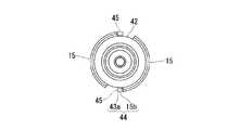
ノズル部11は、装着部10のフランジ部10aの内周側に連続して形成された円筒状の外筒部12と、この外筒部12の内側に配置された円筒状の内筒部13と、これら外筒部12及び内筒部13の上端部に連続して形成されたノズル本体14と、を有している。外筒部12には、その外周面に係止突部15が形成されている。係止突部15は、吐出栓4の平面図である図2、及び吐出栓4の側面図である図3に示すように、径方向の外側に向けて突出し、外筒部12の外周面に周方向に延在して形成された凸条形状のものである。  Thenozzle part 11 includes a cylindricalouter cylinder part 12 formed continuously on the inner peripheral side of theflange part 10 a of the mountingpart 10, and a cylindricalinner cylinder part 13 disposed inside theouter cylinder part 12. And anozzle body 14 formed continuously at the upper end portions of theouter cylinder portion 12 and theinner cylinder portion 13. A lockingprojection 15 is formed on the outer peripheral surface of theouter cylinder portion 12. As shown in FIG. 2, which is a plan view of thedischarge plug 4, and FIG. 3, which is a side view of thedischarge plug 4, the lockingprotrusion 15 protrudes outward in the radial direction, and the outer peripheral surface of theouter cylinder portion 12. It is the thing of the protruding item | line shape formed extending in the circumferential direction.

本実施形態では、係止突部15は外筒部12の外周面の、周方向において一部が切り欠かれたことで、図2に示すように二つ形成されている。これにより、二つの係止突部15は外筒部12の外周面の周方向にて断続的に延在して形成されている。そして、これら係止突部15の一方の側の周端部15aが、後述する基筒部20の規制突部26とともに本発明に係る第1規制部を構成している。このような係止突部15は、後述するキャップ体5の基筒部20の内周面に形成された係合部25に上下方向にて係止しており、これによってキャップ体5を保持固定する部位となっている。  In the present embodiment, two lockingprotrusions 15 are formed as shown in FIG. 2 by partially cutting away the outer peripheral surface of theouter cylinder portion 12 in the circumferential direction. Thereby, the two lockingprojections 15 are formed to extend intermittently in the circumferential direction of the outer peripheral surface of theouter cylinder portion 12. And theperipheral edge part 15a of one side of these latchingprotrusions 15 comprises the 1st control part which concerns on this invention with thecontrol protrusion 26 of thebase cylinder part 20 mentioned later. Such a lockingprojection 15 is locked in the up and down direction to anengagement portion 25 formed on the inner peripheral surface of thebase cylinder portion 20 of thecap body 5 to be described later, thereby holding thecap body 5. It is a fixed part.

図1に示すように内筒部13は、外筒部12の内側に配置されてその上端部が外筒部12の上端部に連結したもので、下端部に円筒状の弁体16を取り付けている。弁体16は、内筒部13の下端部に係合する縦断面U字状の係合部16aと、この係合部16aの径方向内側の上端部に一体に形成された円筒状の弁本体16bと、弁本体16bの径方向外側の上端部に一体に形成された円環状の空気弁16cと、からなっている。この弁体16はエラストマー等の軟材質によって形成されており、弁本体16bおよび空気弁16cは係合部16aに比べて薄肉に形成されている。したがって、弁本体16b、空気弁16cは良好な可撓性(弾性変形性)を有している。内筒部13の下端部には、下方に向けて開口し、かつ径方向に貫くスリット13aが形成されている。スリット13aの上端は、係合部16aの上端より上方に位置している。  As shown in FIG. 1, theinner cylinder portion 13 is arranged inside theouter cylinder portion 12 and its upper end portion is connected to the upper end portion of theouter cylinder portion 12, and a cylindrical valve body 16 is attached to the lower end portion. ing. The valve body 16 includes a U-shapedengaging portion 16a that engages with the lower end portion of the innercylindrical portion 13, and a cylindrical valve that is integrally formed with the radially inner upper end portion of the engagingportion 16a. It consists of amain body 16b and an annular air valve 16c formed integrally with the upper end of thevalve body 16b on the radially outer side. The valve body 16 is formed of a soft material such as an elastomer, and thevalve body 16b and the air valve 16c are formed thinner than the engagingportion 16a. Therefore, thevalve body 16b and the air valve 16c have good flexibility (elastic deformation). A slit 13 a that opens downward and penetrates in the radial direction is formed at the lower end of theinner cylinder portion 13. The upper end of theslit 13a is located above the upper end of the engagingportion 16a.

この弁本体16bの上部開口内にはノズル本体14の栓体17が配置されており、通常時には弁本体16bの上部開口側が閉じて栓体17に係合している。これにより、通常時では容器本体2内は弁本体16bによって液密(又は気密)に封止されている。また、前述したように底部7の底体9が押圧されて容器本体2内が加圧されると、弁本体16bは容易に弾性変形して上部開口が開き、栓体17に対する係合を解除する。これにより、容器本体2内とノズル部11との間が連通し、容器本体2内の内容物の流路が形成される。空気弁16cは、フランジ部10aのうち、装着部10の円筒部10bより径方向内側に位置する部分の下面に当接している。空気弁16cは、径方向内側から外側に向かうに従い漸次上方に向けて延在している。空気弁16cは、底部7の底体9の押圧が解除されたときに、フランジ部10aから離間する。これにより、外気が吐出孔14a、内筒部13内、スリット13aを通して容器本体2内に流入する。この際、吐出孔14a内の内容物も下方に吸い込まれることから、液切れ性が良くなる。  Aplug body 17 of thenozzle body 14 is disposed in the upper opening of thevalve body 16b. Normally, the upper opening side of thevalve body 16b is closed and engaged with theplug body 17. Thereby, in the normal time, the inside of the containermain body 2 is sealed liquid-tight (or air-tight) by the valvemain body 16b. Further, as described above, when the bottom body 9 of thebottom portion 7 is pressed and the inside of thecontainer body 2 is pressurized, thevalve body 16b is easily elastically deformed to open the upper opening, and the engagement with theplug body 17 is released. To do. Thereby, the inside of the containermain body 2 and thenozzle part 11 communicate, and the flow path of the content in the containermain body 2 is formed. The air valve 16c is in contact with the lower surface of a portion of theflange portion 10a that is located radially inward from thecylindrical portion 10b of the mountingportion 10. The air valve 16c extends gradually upward as it goes from the radially inner side to the outer side. The air valve 16c is separated from theflange portion 10a when the bottom body 9 of thebottom portion 7 is released. Thereby, outside air flows in into the containermain body 2 through thedischarge hole 14a, theinner cylinder part 13, and theslit 13a. At this time, since the contents in thedischarge hole 14a are also sucked downward, the liquid breakage is improved.

栓体17は、複数のブリッジ17aを介してノズル本体14の下端開口縁に連結されている。ノズル本体14には、その内部に吐出孔14aが形成されており、この吐出孔14aは前記ブリッジ17a間に連通している。これにより、前記したように弁本体16bの上部開口が開くと、容器本体2内と吐出孔14aとはブリッジ17a間を介して連通する。すなわち、容器本体2内と吐出孔14aとの間に内容物の流路が確保される。また、ノズル本体14には、図1、図3に示すようにその外周面に雄螺子部18が形成されている。  Theplug body 17 is connected to the lower end opening edge of thenozzle body 14 through a plurality ofbridges 17a. Thenozzle body 14 has adischarge hole 14a formed therein, and thedischarge hole 14a communicates with thebridge 17a. Thereby, when the upper opening of the valvemain body 16b is opened as described above, the inside of the containermain body 2 and thedischarge hole 14a communicate with each other via thebridge 17a. That is, a flow path for the contents is ensured between thecontainer body 2 and thedischarge hole 14a. Further, as shown in FIGS. 1 and 3, amale screw portion 18 is formed on the outer peripheral surface of thenozzle body 14.

キャップ体5は、図4に示すように円筒状の本体筒部19と、該本体筒部19より下側(内側)に配設された円筒状の基筒部20と、これら本体筒部19と基筒部20との間に配置されてこれらを連結する弱化部21と、を有している。また、本体筒部19と基筒部20との間には、これら本体筒部19と基筒部20との間を展開して示す図5(a)に示すように、弱化部21とは別に、本体筒部19と基筒部20とを連結する補助連結部22が形成されている。  As shown in FIG. 4, thecap body 5 includes a cylindrical mainbody cylinder portion 19, a cylindricalbase cylinder portion 20 disposed on the lower side (inner side) of the mainbody cylinder portion 19, and the mainbody cylinder portion 19. And a weakeningportion 21 which is arranged between thebase tube portion 20 and connects them. Further, between the mainbody cylinder portion 19 and thebase cylinder portion 20, as shown in FIG. Separately, anauxiliary connecting part 22 that connects the mainbody cylinder part 19 and thebase cylinder part 20 is formed.

図4に示すように本体筒部19には、その内周面に前記ノズル本体14の雄螺子部18に螺着する雌螺子部23が形成されており、これによって本体筒部19は、ノズル部11のノズル本体14に対して移動自在に被着されている。この本体筒部19には、その上端開口部19aの少し下側に、栓体24が設けられている。栓体24は、図1に示すようにノズル本体14の吐出孔14aの上端(先端)開口部に係脱可能に内挿されたもので、これによって吐出孔14aは、栓体24によって開閉可能に閉塞されている。  As shown in FIG. 4, the mainbody cylinder portion 19 is formed with afemale screw portion 23 to be screwed to themale screw portion 18 of the nozzlemain body 14 on the inner peripheral surface thereof. It is movably attached to thenozzle body 14 of thesection 11. The mainbody cylinder portion 19 is provided with aplug 24 slightly below theupper end opening 19a. As shown in FIG. 1, theplug body 24 is removably inserted into the upper end (tip) opening of thedischarge hole 14 a of thenozzle body 14, so that thedischarge hole 14 a can be opened and closed by theplug body 24. Is blocked.

また、栓体24は複数のブリッジ24aを介して本体筒部19の上端部に連結されており、本体筒部19の上端開口部19aはブリッジ24a間に連通している。そして、栓体24は、本体筒部19が廻されてノズル本体14との間の螺着状態が緩められ、ノズル本体14に対して上昇した際、吐出孔14aから外れてこれを開口するようになっている。したがって、本体筒部19を充分に廻してノズル本体14との間の螺着状態を解除し、ノズル本体14から取り外すことで、吐出孔14aを開口できるようになっている。  Theplug 24 is connected to the upper end portion of the mainbody cylinder portion 19 via a plurality ofbridges 24a, and the upperend opening portion 19a of the mainbody cylinder portion 19 communicates between thebridges 24a. Then, theplug 24 is unscrewed from thenozzle body 14 when the mainbody cylinder portion 19 is turned so that theplug body 24 is lifted with respect to thenozzle body 14 so as to be released from thedischarge hole 14a. It has become. Therefore, thedischarge hole 14 a can be opened by sufficiently turning the mainbody cylinder portion 19 to release the screwed state between the mainbody cylinder portion 19 and the nozzlemain body 14 and removing it from the nozzlemain body 14.

基筒部20は、ノズル部11の外筒部12に外嵌されて固着されたもので、図4に示すようにその内周面に周方向に沿って凸条形状の係合部25が形成されている。係合部25は、図1に示すように前記外筒部12の係止突部15に上下方向にて係止している。すなわち、後述するように吐出栓4に対してキャップ体5を取り付けるべく打栓することにより、係合部25が係止突部15を乗り越えることで係合部25が係止突部15に係止している。なお、係合部25も、係止突部15と同様に周方向において一部が切り欠かれたことにより、キャップ体5の底面図である図6に示すように二つ形成されている。  Thebase cylinder part 20 is fitted and fixed to theouter cylinder part 12 of thenozzle part 11, and, as shown in FIG. Is formed. As shown in FIG. 1, the engagingportion 25 is locked to the lockingprojection 15 of theouter tube portion 12 in the vertical direction. That is, as will be described later, theengagement portion 25 is engaged with the lockingprojection 15 by striking thedischarge plug 4 to attach thecap body 5 so that theengagement portion 25 gets over the lockingprojection 15. It has stopped. Note that twoengaging portions 25 are also formed as shown in FIG. 6, which is a bottom view of thecap body 5, by partially cutting away in the circumferential direction in the same manner as the lockingprotrusion 15.

また、基筒部20の内周面には、二つの係合部25間に規制突部26が形成されている。規制突部26は、図4、図6に示すように二つの係合部25のほぼ中間部にそれぞれ配置されたもので、互いに対向して配置されている。これら規制突部26は、上下に延在して形成された凸条形状のもので、図2、図3に示すように二つの係止突部15、15間、すなわち二つの係止突部15、15を一つの係止突部として見た場合の切り欠かれた部位に配置されている。  In addition, a restrictingprotrusion 26 is formed between the twoengaging portions 25 on the inner peripheral surface of thebase tube portion 20. As shown in FIGS. 4 and 6, the restrictingprotrusions 26 are disposed substantially at the intermediate portions of the twoengaging portions 25, and are disposed to face each other. These restrictingprotrusions 26 are convexly formed to extend up and down, and as shown in FIGS. 2 and 3, between the two engagingprotrusions 15 and 15, that is, the two engaging protrusions. 15 and 15 are arranged at a notched portion when viewed as one locking projection.

規制突部26は、後述するように開栓時にキャップ体5を廻した際に、係止突部15の周端部15aに当接することで外筒部12に対する基筒部20の回動を規制するようになっている。すなわち、前記したようにこれら規制突部26と、係止突部15の両周端部のうち、ノズル部11に対してキャップ体5を締め付ける側の周端部15aと、により、本発明に係る第1規制部が構成されている。  As will be described later, when thecap body 5 is turned at the time of opening, the restrictingprotrusion 26 abuts on theperipheral end portion 15a of the lockingprotrusion 15 to rotate thebase tube portion 20 with respect to theouter tube portion 12. It comes to regulate. That is, as described above, therestriction protrusion 26 and theperipheral end 15a on the side where thecap body 5 is tightened with respect to thenozzle portion 11 among the peripheral end portions of the lockingprotrusion 15 are included in the present invention. The 1st control part which concerns is comprised.

図4、図5(a)に示すように弱化部21は、本体筒部19と基筒部20との間にて適宜な数(一又は複数)配置されており、キャップ体5の本体筒部19を開栓するまでの間、本体筒部19と基筒部20との間を繋いでいる。そして、本体筒部19を開栓することで破断し、本体筒部19と基筒部20とを分離させるようになっている。その際、弱化部21が破断したことで、開栓操作がなされたことが容易に確認できるようになっている。このような弱化部21は、例えば径方向の外側から見た側面視で台形状に形成された薄肉の小片であり、所定の剪断力や引張力が加えられることにより、例えば周方向の大きさが狭い側が容易に破断されるようになっている。  As shown in FIG. 4 and FIG. 5A, an appropriate number (one or more) of weakeningportions 21 are arranged between the mainbody cylinder portion 19 and thebase cylinder portion 20, and the main body cylinder of thecap body 5. The mainbody cylinder part 19 and thebase cylinder part 20 are connected until thepart 19 is opened. Then, the mainbody cylinder portion 19 is broken by opening, and the mainbody cylinder portion 19 and thebase cylinder portion 20 are separated. At that time, the weakeningportion 21 is broken, so that it is possible to easily confirm that the opening operation has been performed. Such a weakenedportion 21 is a thin piece formed in a trapezoidal shape as viewed from the outside in the radial direction, for example, and is applied with a predetermined shearing force or tensile force, for example, in the circumferential direction. The narrow side is easily broken.

図5(a)、及び図5(a)のA部拡大図である図5(b)に示すように、補助連結部22は、略矩形状の基部22aと、この基部22aに一体に形成された台形状の薄肉部22bとからなっている。薄肉部22bは、基部22aに比べて薄肉に形成されている。また、薄肉部22bは、基部22aの長辺より幅が狭い下辺を有している。これにより、薄肉部22bは基部22aに比べてその破断強度が弱く形成されている。一方、基部22aは、その破断強度が比較的強く形成されている。このような補助連結部22も、本体筒部19と基筒部20との間にて適宜な数(一又は複数)配置されたことにより、本体筒部19と基筒部20との間を補助的に連結している。  As shown in FIG. 5 (a) and FIG. 5 (b), which is an enlarged view of a portion A in FIG. 5 (a), theauxiliary connecting portion 22 is formed integrally with the substantiallyrectangular base portion 22a and thebase portion 22a. And a trapezoidal thin-walled portion 22b. Thethin portion 22b is formed thinner than thebase portion 22a. Thethin portion 22b has a lower side that is narrower than the long side of thebase portion 22a. Thereby, thethin part 22b is formed so that the breaking strength is weaker than that of thebase part 22a. On the other hand, thebase portion 22a is formed to have a relatively high breaking strength. Such anauxiliary connecting part 22 is also disposed between the mainbody cylinder part 19 and thebase cylinder part 20 by arranging an appropriate number (one or more) between the mainbody cylinder part 19 and thebase cylinder part 20. It is connected supplementarily.

なお、本実施形態では、基部22aを基筒部20の上端部(容器軸O方向の外端部)に配置し、薄肉部22bを本体筒部19側に配置したが、これらを逆に配置してもよい。
補助連結部22の、容器軸O回りに沿う一方の側、すなわち図5(b)中に矢印Bで示す、本体筒部19のノズル部11に対して緩める側には、矩形状の規制片27が形成されている。この規制片27は、補助連結部22に対して予め設定された僅かな間隙を介して、本体筒部19の下端部(容器軸O方向の内端部)に配置されている。
In the present embodiment, thebase portion 22a is disposed at the upper end portion (outer end portion in the container axis O direction) of thebase tube portion 20, and thethin portion 22b is disposed on the mainbody tube portion 19 side. May be.
On one side of the auxiliary connectingpart 22 around the container axis O, that is, on the side loosened with respect to thenozzle part 11 of the mainbody cylinder part 19 as indicated by an arrow B in FIG. 27 is formed. The restrictingpiece 27 is disposed at the lower end portion (the inner end portion in the container axis O direction) of the mainbody cylinder portion 19 with a slight gap set in advance with respect to theauxiliary connecting portion 22.

図5(b)に示すように規制片27の下端は、補助連結部22の基筒部20側に配置された基部22aの上端に対し、下方に位置している。このような構成によって基部22aと規制片27とは、本体筒部19をノズル部11に対して締め付け側(矢印Bと反対の側)に廻した際、基筒部20がノズル部11に固定されていることにより、図5(b)中に二点鎖線で示すように互いに係止され合い、それ以上の回転移動を規制する。すなわち、通常の力で本体筒部19をノズル部11に対して締め付けた際、基部22aと規制片27とが所定以上の回転移動を規制することにより、弱化部21や薄肉部22bが破断してしまうのが防止されている。このような基部22aと規制片27とにより、本発明に係る第2規制部が構成されている。  As shown in FIG. 5B, the lower end of the restrictingpiece 27 is positioned below the upper end of thebase portion 22 a arranged on thebase tube portion 20 side of the auxiliary connectingportion 22. With this configuration, thebase portion 22a and therestriction piece 27 are fixed to thenozzle portion 11 when the mainbody tube portion 19 is turned to the tightening side (the side opposite to the arrow B) with respect to thenozzle portion 11. As a result, they are engaged with each other as shown by a two-dot chain line in FIG. 5B, and further rotational movement is restricted. That is, when the mainbody cylinder portion 19 is fastened to thenozzle portion 11 with a normal force, the weakenedportion 21 and thethin portion 22b are broken by thebase portion 22a and the restrictingpiece 27 restricting the rotational movement more than a predetermined amount. Is prevented. Thebase portion 22a and therestriction piece 27 as described above constitute a second restriction portion according to the present invention.

また、補助連結部22を周方向に挟んで規制片27と反対の側には、略矩形状の補助片28が形成されている。この補助片28は、補助連結部22に対し予め設定された間隙を介して本体筒部19側に配置されたもので、規制片27の上下方向の幅と同じ幅に形成されている。このような構成によって補助片28と規制片27とは、後述するように吐出栓4に対してキャップ体5を取り付けるべく打栓した際、基筒部20がノズル部11に固定されることで本体筒部19が基筒部20側に大きく移動するのを、抑制するようになっている。  Also, a substantially rectangularauxiliary piece 28 is formed on the side opposite to the regulatingpiece 27 with the auxiliary connectingportion 22 sandwiched in the circumferential direction. Theauxiliary piece 28 is disposed on the mainbody cylinder part 19 side with a gap set in advance with respect to theauxiliary connecting part 22, and is formed to have the same width as the vertical width of the regulatingpiece 27. With such a configuration, theauxiliary piece 28 and therestriction piece 27 are fixed to thenozzle portion 11 when thebase tube portion 20 is fixed so as to attach thecap body 5 to thedischarge plug 4 as will be described later. The mainbody cylinder portion 19 is prevented from largely moving toward thebase cylinder portion 20 side.

すなわち、補助片28と規制片27とは、本体筒部19が基筒部20側に移動した際、その基筒部20側の端部が基筒部20に当接若しくは近接するようになっている。したがって、打栓時に過剰な力が加わって本体筒部19が座屈変形により基筒部20側に大きく移動しようとしても、補助片28と規制片27とが互いに協働して基筒部20に当接することにより、それ以上の基筒部20側への移動が規制されている。  That is, theauxiliary piece 28 and the regulatingpiece 27 are configured such that when the mainbody cylinder portion 19 moves to thebase tube portion 20 side, the end portion on thebase tube portion 20 side comes into contact with or approaches thebase tube portion 20. ing. Therefore, even if an excessive force is applied at the time of plugging and the mainbody cylinder portion 19 tends to move largely toward thebase cylinder portion 20 due to buckling deformation, theauxiliary piece 28 and the regulatingpiece 27 cooperate with each other to form thebase cylinder portion 20. Further movement to thebase tube portion 20 side is restricted.

なお、補助片28は、補助連結部22側(キャップ体5を吐出栓4に対して緩める側)の辺の下端の角部が湾曲して形成されており、一方、補助連結部22の基部22aの、補助片28側の辺の上端の角部も湾曲して形成されている。このような構成のもとに、開栓時にキャップ体5を廻して本体筒部19をノズル部11に固定された基筒部20に対し矢印B方向に廻した際、補助片28が基部22aに当接するのが抑制されている。また、仮に当接したとしても、補助片28はその湾曲した角部が基部22aの湾曲した角部に当接することにより、互いに容易に乗り越えられるようになっている。したがって、補助片28が基部22aに当接することで本体筒部19の回転移動が規制されることなく、本体筒部19は円滑に回転移動するようになっている。  Theauxiliary piece 28 is formed by curving the lower corner portion of the side on theauxiliary connecting portion 22 side (the side on which thecap body 5 is loosened with respect to the discharge plug 4), while the base portion of the auxiliary connectingportion 22 is formed. The corner of the upper end of the side of theauxiliary piece 28 side of 22a is also curved. Under such a configuration, when thecap body 5 is turned to open the mainbody tube portion 19 in the direction of the arrow B with respect to thebase tube portion 20 fixed to thenozzle portion 11 at the time of opening the plug, theauxiliary piece 28 becomes thebase portion 22a. It is suppressed that it contacts. Even if theauxiliary pieces 28 come into contact with each other, the curved corners of theauxiliary pieces 28 come into contact with the curved corners of thebase portion 22a so that they can easily get over each other. Therefore, the mainbody cylinder portion 19 smoothly rotates without restricting the rotation movement of the mainbody cylinder portion 19 by theauxiliary piece 28 coming into contact with thebase portion 22a.

また、本実施形態では規制片27及び補助片28を本体筒部19側に形成したが、これら規制片27、補助片28は補助連結部22の基部22aと反対の側に配置されるものであり、基部22aを本体筒部19側に形成した場合には、当然ながら規制片27及び補助片28は基筒部20側に形成される。  In the present embodiment, therestriction piece 27 and theauxiliary piece 28 are formed on the mainbody cylinder portion 19 side. However, therestriction piece 27 and theauxiliary piece 28 are disposed on the side opposite to thebase portion 22a of the auxiliary connectingportion 22. In the case where thebase portion 22a is formed on the mainbody cylinder portion 19 side, therestriction piece 27 and theauxiliary piece 28 are naturally formed on thebase tube portion 20 side.

(封緘容器の作用)
このような構成からなる封緘容器1を製造するには、まず、容器本体2の口部3内に吐出栓4の外筒部12を嵌合させ、吐出栓4を取り付ける。次に、吐出栓4に対してキャップ体5を取り付けるべく、吐出栓4の上方からキャップ体5を被せ、その状態でキャップ体5に所定の力を加え、打栓を行う。これにより、基筒部20の内周面の係合部25を外筒部12の外周面の係止突部15に対して乗り越えさせ、係止させる。
(Operation of sealed container)
In order to manufacture the sealedcontainer 1 having such a configuration, first, theouter cylinder portion 12 of thedischarge plug 4 is fitted into themouth 3 of thecontainer body 2 and thedischarge plug 4 is attached. Next, in order to attach thecap body 5 to thedischarge plug 4, thecap body 5 is covered from above thedischarge plug 4, and a predetermined force is applied to thecap body 5 in this state to perform plugging. As a result, the engagingportion 25 on the inner peripheral surface of thebase tube portion 20 gets over the lockingprotrusion 15 on the outer peripheral surface of theouter tube portion 12 and is locked.

ここで、打栓を行った際、打栓時の力によって弱化部21が不測に破断しないように、従来に比べて例えば係合部25や係止突部15の高さを低くしたり、弱化部21自体の強度を強くしておくのが好ましい。
このような打栓を行った際に過剰な力がキャップ体5に加わると、座屈変形によって弱化部21が破断してしまうおそれがある。しかし、座屈変形により本体筒部19が基筒部20側に大きく移動しようとしても、本体筒部19に規制片27と補助片28とを設けたことにより、これらが互いに協働して基筒部20に当接するため、それ以上の基筒部20側への移動が規制される。したがって、弱化部21の破断が防止される。
Here, when performing the stoppering, for example, the height of theengaging part 25 and the lockingprotrusion 15 is reduced compared to the conventional one so that the weakenedpart 21 does not break unexpectedly due to the force at the time of stoppering, It is preferable to increase the strength of the weakenedportion 21 itself.
If an excessive force is applied to thecap body 5 when performing such a plugging, the weakenedportion 21 may be broken by buckling deformation. However, even if the mainbody cylinder portion 19 tends to move largely toward thebase cylinder portion 20 due to buckling deformation, the mainbody cylinder portion 19 is provided with therestriction piece 27 and theauxiliary piece 28, so that they cooperate with each other. Since it contacts thecylinder part 20, the further movement to thebase cylinder part 20 side is controlled. Therefore, breakage of the weakenedportion 21 is prevented.

また、このようにして打栓を行う際には、図2、図3に示すように、規制突部26が二つの係止突部15、15間に入り込むように、位置決めした状態で行う。しかし、吐出栓4に対するキャップ体5の位置決めを充分に行っても、ノズル本体14の雄螺子部18と、本体筒部19の雌螺子部23との間の螺着状態は良好な状態に嵌め込まれないことがある。  Moreover, when performing the plugging in this way, as shown in FIGS. 2 and 3, it is performed in a state where the restrictingprotrusion 26 is positioned so as to enter between the two lockingprotrusions 15 and 15. However, even if thecap body 5 is sufficiently positioned with respect to thedischarge plug 4, the screwed state between themale screw part 18 of thenozzle body 14 and thefemale screw part 23 of the mainbody cylinder part 19 is fitted in a good state. May not be.

そこで、通常は打栓工程後、キャップ体5を少し締め付け、雄螺子部18と雌螺子部23との間の螺着状態を設定された良好な状態にする。その際、キャップ体5を過剰に締め付けると弱化部21が破断してしまうおそれがあるが、図5に示したように第2規制部を構成する規制片27が基部22aに当接して本体筒部19(キャップ体5)の過剰な締め付けが防止されていることにより、弱化部21の破断が防止される。  Therefore, usually, after the plugging step, thecap body 5 is slightly tightened to bring the screwed state between themale screw portion 18 and thefemale screw portion 23 into a set good state. At this time, if thecap body 5 is excessively tightened, the weakenedportion 21 may be broken. However, as shown in FIG. 5, the regulatingpiece 27 constituting the second regulating portion comes into contact with thebase portion 22a and the main body cylinder. By preventing excessive tightening of the portion 19 (cap body 5), the weakenedportion 21 is prevented from being broken.

このようにして製造された封緘容器1を使用するには、まず、キャップ体5を開栓して弱化部21及び補助連結部22を破断し、本体筒部19を基筒部20から分離する。その際、図2、図3に示したように規制突部26が係止突部15の周端部15aに当接することで外筒部12に対する基筒部20の回動が規制されているため、たとえ係合部25や係止突部15の高さを低くしたり、弱化部21自体の強度を強くしていても、外筒部12の係止突部15に対する基筒部20の係合部25の係止が外れることがなく、したがって弱化部21が確実に破断するようになる。  In order to use the sealedcontainer 1 manufactured in this manner, first, thecap body 5 is opened, the weakenedportion 21 and the auxiliary connectingportion 22 are broken, and the main bodycylindrical portion 19 is separated from the basecylindrical portion 20. . At that time, as shown in FIGS. 2 and 3, therestriction projection 26 abuts on theperipheral end portion 15 a of the lockingprojection 15, so that the rotation of thebase tube portion 20 with respect to theouter tube portion 12 is restricted. Therefore, even if the height of the engagingportion 25 or the lockingprojection 15 is lowered or the strength of the weakenedportion 21 itself is increased, thebase tube portion 20 of theouter tube portion 12 with respect to the lockingprojection 15 is increased. Theengagement portion 25 is not unlocked, and therefore the weakenedportion 21 is reliably broken.

このように弱化部21が破断することで、この封緘容器1は開栓されていることが容易に確認できるようになる。そして、使用に際しては、基筒部20から分離された本体筒部19をさらに廻すことでノズル本体14から取り外し、その状態で底部7の底体9を押圧することにより、内容物をノズル本体14の吐出孔14aから吐出させる。その際、封緘容器1については、ノズル部11を上に向けたままで使用しても、また、ノズル部11を下に向けた倒立姿勢にして使用してもよい。  As the weakenedportion 21 breaks in this way, it can be easily confirmed that the sealedcontainer 1 is opened. In use, the mainbody cylinder portion 19 separated from thebase cylinder portion 20 is further rotated to be removed from the nozzlemain body 14, and the bottom body 9 of thebottom portion 7 is pressed in this state, whereby the contents are removed from the nozzlemain body 14. From thedischarge hole 14a. At that time, the sealingcontainer 1 may be used with thenozzle portion 11 facing upward, or may be used in an inverted posture with thenozzle portion 11 facing downward.

このような封緘容器1にあっては、ノズル部11の外筒部12の外周面、および基筒部20の内周面にそれぞれ、第1規制部を構成する係止突部15の周端部15a、規制突部26を形成したので、使用に際しての開封時にキャップ体5を廻した際に、第1規制部によりノズル部11に対して基筒部20が容器軸O回りに回転することを規制することができる。したがって、ノズル部11に対する基筒部20の係止(嵌合)が外れることを防止し、弱化部21を確実に破断することができる。よって、打栓時(製造時)に弱化部21が破断するのを防止しつつ、開栓時に弱化部21を確実に破断することができる。  In such asealing container 1, the peripheral ends of the lockingprojections 15 constituting the first restricting portions on the outer peripheral surface of the outercylindrical portion 12 of thenozzle portion 11 and the inner peripheral surface of the basecylindrical portion 20, respectively. Since thepart 15a and theregulation protrusion 26 are formed, thebase cylinder part 20 is rotated around the container axis O with respect to thenozzle part 11 by the first regulation part when thecap body 5 is rotated at the time of opening for use. Can be regulated. Therefore, it is possible to prevent the locking (fitting) of thebase tube portion 20 from thenozzle portion 11 from being released, and the weakenedportion 21 can be reliably broken. Therefore, it is possible to reliably break the weakenedportion 21 when opening the plug while preventing the weakenedportion 21 from being broken at the time of plugging (manufacturing).

ここで、キャップ体5が小径の場合、開封に際し、弱化部21に作用するトルクが小さくなりやすいため、需要者は大きな力を加える必要がある。そのため、小径のキャップ体5を有する封緘容器1において、開封のしやすさを具備させるためには、弱化部21の破断強度を小さくする必要がある。
しかしながら、この場合、キャップ体5をノズル部11に打栓する際に、弱化部21が不意に破断しやすくなるおそれがあるため、係止突部15の突出高さを低く抑えることで、打栓時の押圧力を押さえる必要もある。
ところがこの場合では、開封時に、係合部25が係止突部15を上方に乗り越えやすくなり、弱化部21が破断しにくくなるおそれがある。
しかしながら、本実施形態による封緘容器1では、弱化部21の破断強度、および係止突部15の突出高さの双方を低く抑えることによって、キャップ体5をノズル部11に打栓する際に、弱化部21が破断するのを抑制しつつ、小径のキャップ体5を有する封緘容器1の良好な開封性を具備させたとしても、第1規制部によりノズル部11に対して基筒部20が容器軸O回りに回転することを規制することが可能になり、弱化部21を確実に破断することができる。
Here, when thecap body 5 has a small diameter, the torque that acts on the weakenedportion 21 tends to be small at the time of opening, and thus the consumer needs to apply a large force. Therefore, in the sealedcontainer 1 having the small-diameter cap body 5, it is necessary to reduce the breaking strength of the weakenedportion 21 in order to provide easy opening.
However, in this case, when thecap body 5 is plugged into thenozzle portion 11, the weakenedportion 21 may be easily broken unexpectedly. It is also necessary to reduce the pressing force when plugging.
However, in this case, at the time of opening, the engagingportion 25 easily gets over the lockingprojection 15 upward, and the weakenedportion 21 may not be easily broken.
However, in the sealedcontainer 1 according to the present embodiment, when thecap body 5 is plugged into thenozzle portion 11 by suppressing both the breaking strength of the weakenedportion 21 and the protruding height of the lockingprojection 15, Even if the opening portion of the sealedcontainer 1 having the small-diameter cap body 5 is provided while suppressing the weakeningportion 21 from breaking, the first restriction portion causes thebase tube portion 20 to be in thenozzle portion 11. It is possible to restrict the rotation around the container axis O, and the weakenedportion 21 can be reliably broken.

また、第1規制部を係止突15部における周端部15aと規制突部26とによって構成しているので、キャップ体5を廻した際に規制突部26が係止突部15における周端部15aに係止することで、ノズル部11に対して基筒部20が容器軸O回りに回転することを確実に規制することができる。したがって、弱化部21をより確実に破断することができる。  Further, since the first restricting portion is constituted by theperipheral end portion 15 a and the restrictingprotrusion 26 in the lockingprotrusion 15, the restrictingprotrusion 26 is rotated around the engagingprotrusion 15 when thecap body 5 is turned. By engaging with theend portion 15a, the rotation of thebase tube portion 20 around the container axis O with respect to thenozzle portion 11 can be reliably controlled. Accordingly, the weakenedportion 21 can be broken more reliably.

また、本体筒部19、及び基筒部20にそれぞれ、互いが係止され合って容器軸O回りに沿う本体筒部19の、ノズル部11に対する締め付け側への回転移動を規制する第2規制部を、補助連結部22の基部22aと規制片27とによって形成しているので、例えば製造時にノズル部11に対する本体筒部19の螺着状態を調整すべく、キャップ体5をノズル部11に対する締め付け側に廻した場合に、第2規制部によって基筒部20に対する本体筒部19の回転移動を規制しているので、誤って弱化部21を破断してしまうことを防止することができる。  Further, the second restriction that restricts the rotational movement of the mainbody cylinder part 19 along the container axis O to the tightening side with respect to thenozzle part 11 while being locked to each other by the mainbody cylinder part 19 and thebase cylinder part 20. Since the portion is formed by thebase portion 22a of the auxiliary connectingportion 22 and therestriction piece 27, for example, thecap body 5 is attached to thenozzle portion 11 in order to adjust the screwed state of the mainbody cylinder portion 19 with respect to thenozzle portion 11 during manufacturing. When turned to the tightening side, the second restricting part restricts the rotational movement of the mainbody cylinder part 19 with respect to thebase cylinder part 20, so that the weakenedpart 21 can be prevented from being broken accidentally.

また、第2規制部の規制片27、及び補助片28を本体筒部19における上下方向の内端部(下端部)に形成しているので、打栓時に本体筒部19と基筒部20との間に過剰な力が加わって本体筒部19が基筒部20側に移動しても、規制片27、補助片28が協働して基筒部20に当接するため、本体筒部19のそれ以上の基筒部20側への移動が規制される。したがって、打栓時における弱化部21の破断を防止することができる。  Further, since therestriction piece 27 and theauxiliary piece 28 of the second restriction portion are formed on the inner end portion (lower end portion) of the mainbody cylinder portion 19 in the vertical direction, the mainbody cylinder portion 19 and thebase cylinder portion 20 at the time of plugging. Even if an excessive force is applied between the mainbody cylinder part 19 and thebase cylinder part 20 side, the regulatingpiece 27 and theauxiliary piece 28 cooperate to contact thebase cylinder part 20. Further movement of 19 toward thebase tube 20 is restricted. Therefore, it is possible to prevent the weakenedportion 21 from being broken during the stoppering.

「第2実施形態」
次に、本発明に係る封緘容器の第2実施形態を説明する。この第2実施形態の封緘容器が第1実施形態の封緘容器1と異なるところは、図7〜図9に示すように、第1規制部を構成する係止突部15の周端部の構造にある。なお、図7は第2実施形態に係る吐出栓30の平面図、図8は同じく吐出栓の側面図、図9は同じく吐出栓の斜視図である。
“Second Embodiment”
Next, a second embodiment of the sealed container according to the present invention will be described. The sealing container of the second embodiment is different from the sealingcontainer 1 of the first embodiment as shown in FIGS. 7 to 9 in the structure of the peripheral end portion of the lockingprojection 15 constituting the first restricting portion. It is in. 7 is a plan view of thedischarge plug 30 according to the second embodiment, FIG. 8 is a side view of the discharge plug, and FIG. 9 is a perspective view of the discharge plug.

図7〜図9に示すように係止突部15には、その一方の側、すなわちノズル部11に対してキャップ体5を締め付ける側に、周端突部31が連続して形成されている。この周端突部31は、前記した規制突部26と同様に、上下に延在して形成された凸条形状のもので、係止突部15の周端部を構成している。これによって周端突部31は、規制突部26とともに本発明に係る第1規制部を構成している。  As shown in FIGS. 7 to 9, the lockingprotrusion 15 has aperipheral end protrusion 31 continuously formed on one side thereof, that is, on the side where thecap body 5 is tightened with respect to thenozzle portion 11. . Theperipheral end protrusion 31 is a convex strip formed extending up and down in the same manner as therestriction protrusion 26 described above, and constitutes the peripheral end of the lockingprotrusion 15. Thus, theperipheral end protrusion 31 constitutes the first restricting portion according to the present invention together with the restrictingprotrusion 26.

本実施形態では、このような周端突部31によって第1規制部を構成していることにより、使用に際しての開封時にキャップ体5を廻した際に、規制突部26が係止突部15における周端突部31により大きな面積で当接し、確実に係止するようになる。したがって、ノズル部11に対して基筒部20が容器軸O回りに回転することを確実に規制し、弱化部21をより確実に破断することができる。  In the present embodiment, the first restricting portion is constituted by such aperipheral end protrusion 31, and therefore, when thecap body 5 is rotated at the time of opening at the time of use, the restrictingprotrusion 26 is engaged with the lockingprotrusion 15. Theperipheral end protrusion 31 in this contact is made with a large area and is surely locked. Therefore, the rotation of thebase tube portion 20 around the container axis O with respect to thenozzle portion 11 can be reliably controlled, and the weakenedportion 21 can be broken more reliably.

「第3実施形態」
次に、本発明に係る封緘容器の第3実施形態を説明する。この第3実施形態の封緘容器が第1実施形態の封緘容器1と異なるところは、図10〜図12に示すように、第1規制部を構成する係止突部15の周端部を含む、ノズル部11の構造にある。なお、図10は第3実施形態に係る吐出栓40の平面図、図11は同じく吐出栓の側面図、図12は同じく吐出栓の斜視図である。
“Third Embodiment”
Next, a third embodiment of the sealed container according to the present invention will be described. The sealing container of the third embodiment is different from the sealingcontainer 1 of the first embodiment, as shown in FIGS. 10 to 12, including the peripheral end portion of the lockingprojection 15 constituting the first restricting portion. In the structure of thenozzle portion 11. 10 is a plan view of thedischarge plug 40 according to the third embodiment, FIG. 11 is a side view of the discharge plug, and FIG. 12 is a perspective view of the discharge plug.

図10〜図12に示すように本実施形態に係る吐出栓40は、そのノズル部41の外筒部42の、二つの係止突部15、15間の外周面が上下方向に切り欠かれて切欠部43が形成されている。そして、係止突部15の一方の側、すなわちノズル部11に対してキャップ体5を締め付ける側の係止突部15の周端側端面15bと、これに連続する切欠端面43aとが、係止突部15の周端部44を構成している。これによって周端側端面15bと切欠端面43aとからなる周端部44は、規制突部45とともに本発明に係る第1規制部を構成している。  As shown in FIGS. 10 to 12, thedischarge plug 40 according to the present embodiment has the outer peripheral surface between the two lockingprojections 15 and 15 of theouter cylinder portion 42 of thenozzle portion 41 cut away in the vertical direction. Thus, anotch 43 is formed. Then, one end of the lockingprojection 15, that is, the peripheral endside end surface 15 b of the lockingprojection 15 on the side that tightens thecap body 5 with respect to thenozzle portion 11, and thenotch end surface 43 a continuous therewith are engaged. Aperipheral end 44 of thestop projection 15 is configured. Accordingly, theperipheral end portion 44 including the peripheral endside end surface 15 b and the cutout end surface 43 a constitutes the first restricting portion according to the present invention together with the restrictingprotrusion 45.

また、本実施形態の規制突部45は、図10中に二点鎖線で示すように図2に示した規制突部26よりその径方向内側に突出する高さが高く形成されている。これにより、規制突部45は係止突部15の周端側端面15bだけでなく、切欠端面43aにも当接してこれに係止するようになっている。  Further, as shown by a two-dot chain line in FIG. 10, therestriction protrusion 45 of the present embodiment is formed to have a height that protrudes radially inward from therestriction protrusion 26 shown in FIG. 2. As a result, the restrictingprojection 45 is brought into contact with and locked to thenotch end surface 43a as well as the peripheralend side surface 15b of the lockingprojection 15.

本実施形態では、このような規制突部45と周端部44とによって第1規制部を構成していることにより、使用に際しての開封時にキャップ体5を廻した際に、規制突部45が係止突部15における周端部44により大きな面積で当接し、確実に係止するようになる。したがって、ノズル部11に対して基筒部20が容器軸O回りに回転することを確実に規制し、弱化部21をより確実に破断することができる。  In the present embodiment, such arestriction protrusion 45 and theperipheral end portion 44 constitute a first restriction portion, so that when thecap body 5 is rotated during opening during use, therestriction protrusion 45 is It comes into contact with theperipheral end 44 of the lockingprojection 15 with a large area and is securely locked. Therefore, the rotation of thebase tube portion 20 around the container axis O with respect to thenozzle portion 11 can be reliably controlled, and the weakenedportion 21 can be broken more reliably.

「第4実施形態」
次に、本発明に係る封緘容器の第4実施形態を説明する。この第4実施形態の封緘容器が第1実施形態の封緘容器1と異なるところは、図13、図14に示すように、第1規制部を構成する係止突部15の周端部を含む、ノズル部11の構造にある。なお、図13は第4実施形態に係る吐出栓50の平面図、図14は同じく吐出栓の側面図である。
“Fourth Embodiment”
Next, a fourth embodiment of the sealed container according to the present invention will be described. The sealing container of the fourth embodiment is different from the sealingcontainer 1 of the first embodiment, as shown in FIGS. 13 and 14, including the peripheral end of the lockingprojection 15 constituting the first restricting part. In the structure of thenozzle portion 11. FIG. 13 is a plan view of adischarge plug 50 according to the fourth embodiment, and FIG. 14 is a side view of the discharge plug.

図13、図14に示すように本実施形態に係る吐出栓50は、そのノズル部51の外筒部52の係止突部53が、周方向に沿って4つ形成されている。これら4つの係止突部53は、周方向の一方の側から他方の側に向かって、すなわち、ノズル部51に対してキャップ体5を締め付ける側から緩める側に向かって、漸次その高さが低くなるように一部が切り欠かれて傾斜したラチェット状に形成されている。  As shown in FIGS. 13 and 14, thedischarge plug 50 according to the present embodiment has four lockingprotrusions 53 of theouter cylinder portion 52 of thenozzle portion 51 formed along the circumferential direction. These four lockingprojections 53 gradually increase in height from one side in the circumferential direction to the other side, that is, from the side of tightening thecap body 5 with respect to thenozzle unit 51 to the side of loosening. It is formed in a ratchet shape that is partly cut out and inclined so as to be lowered.

そして、これら4つの係止突部53間の段差部、すなわちノズル部51に対してキャップ体5を締め付ける側の端面が、係止突部53の周端部53aとなっており、この周端部53aが規制突部26とともに本発明に係る第1規制部を構成している。なお、本実施形態では、4つの係止突部53に対応して、規制突部26も4つ形成されていてもよい。  A stepped portion between the fourlocking projections 53, that is, an end surface on the side where thecap body 5 is tightened with respect to thenozzle portion 51 is aperipheral end portion 53a of the lockingprojection 53. Theportion 53a constitutes the first restricting portion according to the present invention together with the restrictingprotrusion 26. In the present embodiment, four restrictingprotrusions 26 may be formed corresponding to the four lockingprotrusions 53.

本実施形態では、このような周端部53aと規制突部26とによって第1規制部を構成していることにより、使用に際しての開封時にキャップ体5を廻した際に、規制突部26が係止突部53における周端部53aに確実に係止するようになる。
また、吐出栓50に対してキャップ体5を被着させる打栓時において、基筒部20の係合部25を係止突部53に係止させた後、雄螺子部18と雌螺子部23との螺着状態を調整する際に、規制突部26を係合突部53に乗り上げさせることが可能になる。したがって、打栓時に周方向の位置を精度良く合わせる必要がないため、吐出栓50に対するキャップ体5の組み付けを容易に行うことができる。
In the present embodiment, such aperipheral end portion 53a and the restrictingprotrusion 26 constitute a first restricting portion, so that when thecap body 5 is rotated during opening in use, the restrictingprotrusion 26 is The lockingprotrusion 53 is securely locked to theperipheral end 53a.
Further, when thecap member 5 is attached to thedischarge plug 50, themale screw portion 18 and the female screw portion are engaged after the engagingportion 25 of thebase tube portion 20 is locked to the lockingprotrusion 53. When adjusting the screwed state with 23, the restrictingprotrusion 26 can be ridden on the engagingprotrusion 53. Therefore, since it is not necessary to match the position in the circumferential direction with high accuracy when plugging, thecap body 5 can be easily assembled to thedischarge plug 50.

なお、本発明の技術範囲は、前記実施形態に限定されるものではなく、本発明の趣旨を逸脱しない範囲において、種々の変更を加えることが可能である。
例えば、容器本体2については、インジェクション成形によって形成するのに代えて、射出成形によって有底筒状に形成されたプリフォームをブロー成形することで形成して、スクイズ容器としてもよい。
The technical scope of the present invention is not limited to the above embodiment, and various modifications can be made without departing from the spirit of the present invention.
For example, thecontainer body 2 may be formed by blow molding a preform formed into a bottomed cylinder by injection molding instead of being formed by injection molding, and may be a squeeze container.

また、使用に際しては、本体筒部19をノズル本体14から外して吐出孔14aを開口させ、底体9を押圧することで容器本体2の内容物を吐出孔14aから吐出させるようにしたが、本体筒部19をノズル本体14から取り外すことなく、本体筒部19を少し廻してノズル本体14との間の螺着状態を緩め、吐出孔14aと上端開口部19aとを連通させることにより、内容物を吐出させることもできる。すなわち、本体筒部19とノズル本体14との間の螺着状態を緩めて吐出孔14aと上端開口部19aとを連通させることにより、容器本体2内の内容物を吐出孔14aから吐出させ、さらに上端開口部19aから吐出させることができる。  In use, the mainbody cylinder portion 19 is removed from thenozzle body 14 to open thedischarge hole 14a, and the bottom body 9 is pressed to discharge the contents of thecontainer body 2 from thedischarge hole 14a. Without removing the mainbody cylinder portion 19 from the nozzlemain body 14, the mainbody cylinder portion 19 is slightly turned to loosen the screwed state between the nozzlemain body 14 and thedischarge hole 14a and the upperend opening portion 19a to communicate with each other. Objects can also be discharged. That is, the contents in thecontainer body 2 are discharged from thedischarge hole 14a by loosening the screwed state between the mainbody cylinder portion 19 and thenozzle body 14 and communicating thedischarge hole 14a with the upperend opening portion 19a. Further, the ink can be discharged from theupper end opening 19a.

1…封緘容器、2…容器本体、3…口部、4…吐出栓、5…キャップ体、10…装着部、11…ノズル部、14…ノズル本体、14a…吐出口、15…係止突部、15a…周端部、15b…周端側端面、19…本体筒部、20…基筒部、21…弱化部、22…補助連結部、22a…基部、22b…薄肉部、25…係合部、30…吐出栓、31…周端突部、40…吐出栓、41…ノズル部、43…切欠部、43a…切欠端面、44…周端部、50…吐出栓、51…ノズル部、53…係止突部、53a…周端部、O…容器軸DESCRIPTION OFSYMBOLS 1 ... Sealing container, 2 ... Container main body, 3 ... Mouth part, 4 ... Discharge stopper, 5 ... Cap body, 10 ... Mounting part, 11 ... Nozzle part, 14 ... Nozzle main body, 14a ... Discharge port, 15 ... Lockingprotrusion 15a ... peripheral end part, 15b ... peripheral end side end face, 19 ... main body cylinder part, 20 ... base cylinder part, 21 ... weakening part, 22 ... auxiliary connection part, 22a ... base part, 22b ... thin wall part, 25 ... engagement Joint part, 30 ... discharge plug, 31 ... peripheral end protrusion, 40 ... discharge plug, 41 ... nozzle part, 43 ... notch part, 43a ... notch end surface, 44 ... peripheral end part, 50 ... discharge stopper, 51 ...nozzle part 53 ... Locking protrusion, 53a ... Peripheral end, O ... Container shaft

Claims (3)

Translated fromJapanese
内容物が収容される容器本体の口部に装着される装着部、及び、該装着部から容器軸方向の外側に向けて突出し、かつその先端に内容物の吐出される吐出孔が形成されたノズル部を有する吐出栓と、
前記吐出栓に装着されるキャップ体と、を備え、
前記キャップ体は、前記ノズル部に移動自在に螺着されて前記吐出孔を開閉する本体筒部と、該本体筒部より容器軸方向の内側に配設され、前記ノズル部に外嵌されて固着された基筒部と、前記本体筒部と前記基筒部とを連結し、かつ破断自在に形成された弱化部と、を備える封緘容器であって、
前記ノズル部の外周面、及び前記基筒部の内周面にはそれぞれ、互いに係止され合って容器軸回りの回転移動を規制する第1規制部が各別に形成されており、
前記ノズル部の外周面には、径方向の外側に向けて突出し、前記基筒部の内周面に形成された係合部に係止される係止突部が形成され、
前記係止突部は、前記ノズル部の外周面に容器軸回りに沿う周方向に延在するとともに、その周方向において少なくとも一部が切り欠かれたことで周方向に断続的に延在して形成され、
前記基筒部の内周面には、前記係止突部の切り欠かれた部位に配置され、前記容器軸方向で前記係合部より前記容器軸方向の内側まで延在する規制突部が形成され、
前記第1規制部は、前記係止突部における周端部と、前記規制突部とによって構成されていることを特徴とする封緘容器。
A mounting portion to be mounted on the mouth portion of the container main body in which the contents are accommodated, and a discharge hole that protrudes outward from the mounting portion in the container axial direction and discharges the contents is formed at the tip thereof. A discharge stopper having a nozzle portion;
A cap body attached to the discharge tap,
The cap body is movably screwed to the nozzle part and is disposed on the inner side in the container axial direction from the main body cylinder part to open and close the discharge hole, and is externally fitted to the nozzle part. A sealed container comprising: a fixed base tube portion; a weakened portion that connects the main body tube portion and the base tube portion and is formed to be fragile;
Each of the outer peripheral surface of the nozzle portion and the inner peripheral surface of the base tube portion is formed with a first restricting portion that is engaged with each other and restricts rotational movement around the container axis.
On the outer peripheral surface of the nozzle portion, a locking projection that protrudes toward the outside in the radial direction and is locked to the engaging portion formed on the inner peripheral surface of the base tube portion is formed,
The locking projection extends in the circumferential direction along the circumference of the container axis on the outer peripheral surface of the nozzle portion, and extends intermittently in the circumferential direction by being cut out at least partially in the circumferential direction. Formed,
On the inner peripheral surface of the base tube portion, there is a restriction protrusion that is disposed at a notched portion of the locking protrusion and extends from the engagement portion to the inside in the container axis direction in the container axis direction. Formed,
The said 1st control part is comprised by the peripheral end part in the said latching protrusion, and the said control protrusion, The sealing container characterized by the above-mentioned.
前記本体筒部、及び前記基筒部にはそれぞれ、互いが係止され合って容器軸回りに沿う本体筒部の、前記ノズル部に対する締め付け側への回転移動を規制する第2規制部が各別に形成されていることを特徴とする請求項1に記載の封緘容器。Each of the main body cylinder part and the base cylinder part has a second restriction part for restricting the rotational movement of the main body cylinder part along the axis of the container along the container axis to the tightening side with respect to the nozzle part. The sealed container according toclaim 1 , wherein the sealed container is formed separately. 前記第2規制部は、前記本体筒部における容器軸方向の内端部、及び前記基筒部における容器軸方向の外端部に各別に形成され、
前記本体筒部、及び前記基筒部のうちの少なくとも一方に形成された前記第2規制部は、他方に容器軸方向に対向しており、前記吐出栓に前記キャップ体を打栓する際に、前記他方に当接若しくは近接することを特徴とする請求項2に記載の封緘容器。
The second restricting portion is formed separately at an inner end portion in the container axial direction of the main body cylindrical portion and an outer end portion in the container axial direction of the base cylindrical portion,
The second restricting portion formed in at least one of the main body cylinder portion and the base cylinder portion is opposed to the other in the container axial direction, and when the cap body is plugged into the discharge plug The sealed container according toclaim 2 , wherein the sealed container is in contact with or close to the other.
JP2014176116A2014-08-292014-08-29 Sealed containerActiveJP6373128B2 (en)

Priority Applications (1)

Application NumberPriority DateFiling DateTitle
JP2014176116AJP6373128B2 (en)2014-08-292014-08-29 Sealed container

Applications Claiming Priority (1)

Application NumberPriority DateFiling DateTitle
JP2014176116AJP6373128B2 (en)2014-08-292014-08-29 Sealed container

Publications (2)

Publication NumberPublication Date
JP2016050001A JP2016050001A (en)2016-04-11
JP6373128B2true JP6373128B2 (en)2018-08-15

Family

ID=55657810

Family Applications (1)

Application NumberTitlePriority DateFiling Date
JP2014176116AActiveJP6373128B2 (en)2014-08-292014-08-29 Sealed container

Country Status (1)

CountryLink
JP (1)JP6373128B2 (en)

Families Citing this family (1)

* Cited by examiner, † Cited by third party
Publication numberPriority datePublication dateAssigneeTitle
JP2020142837A (en)*2019-03-072020-09-10凸版印刷株式会社Tube container

Family Cites Families (6)

* Cited by examiner, † Cited by third party
Publication numberPriority datePublication dateAssigneeTitle
DE9212753U1 (en)*1992-09-221992-11-26Georg Menshen GmbH & Co KG, 57413 Finnentrop Tamper-evident seal
JP3363863B2 (en)*2000-01-312003-01-08喜久二 山口 Virgin-sealed container and method of assembling the same
JP2006232298A (en)*2005-02-232006-09-07Toyo Kogei Kogyo Co LtdSeparately disposable two piece cap with fraudulent unsealing preventive function
JP2006306482A (en)*2005-05-022006-11-09Toto Seikei KkTamper-evident cap
JP5152753B2 (en)*2008-01-312013-02-27株式会社吉野工業所 Synthetic resin pouring cap
JP5732242B2 (en)*2010-12-032015-06-10三笠産業株式会社 Plastic cap

Also Published As

Publication numberPublication date
JP2016050001A (en)2016-04-11

Similar Documents

PublicationPublication DateTitle
US10315808B2 (en)Container closure cap and container closure
JP4874336B2 (en) Package that can be converted to child resistant closure and non-child resistant operation
JP7262306B2 (en) cap
JP6373128B2 (en) Sealed container
JP2023020386A (en) container with cap
JP7236923B2 (en) hinge cap
KR100985326B1 (en) Closures for liquid containers with sealing devices that leave open traces
JP6017981B2 (en) Cap with inner plug
JP4925401B2 (en) Dispensing tool with function to prevent unsealing during distribution
JP4864668B2 (en) Dissimilar material assembly container
JP6640048B2 (en) Container with hinge cap
JP2010126199A (en)Coating container
JP2018016378A (en)Discharge container
JP2013203448A (en)Container lid
JP4906560B2 (en) Plastic container lid
JP2018016407A (en) Discharge container
JP5774348B2 (en) Cap for container
JP2020172325A (en)cap
JP4704785B2 (en) Ratchet screw cap
JP6701024B2 (en) Discharge container
JP2019210054A (en)Cap with sealing portion
JP7348789B2 (en) Synthetic resin cap
JP4470155B2 (en) Tamper evidence structure of cap with cap
JP7149891B2 (en) hinge cap
JP7005267B2 (en) Synthetic resin caps and containers

Legal Events

DateCodeTitleDescription
A621Written request for application examination

Free format text:JAPANESE INTERMEDIATE CODE: A621

Effective date:20170301

A977Report on retrieval

Free format text:JAPANESE INTERMEDIATE CODE: A971007

Effective date:20180118

A131Notification of reasons for refusal

Free format text:JAPANESE INTERMEDIATE CODE: A131

Effective date:20180130

A521Written amendment

Free format text:JAPANESE INTERMEDIATE CODE: A523

Effective date:20180316

A131Notification of reasons for refusal

Free format text:JAPANESE INTERMEDIATE CODE: A131

Effective date:20180508

A521Written amendment

Free format text:JAPANESE INTERMEDIATE CODE: A523

Effective date:20180607

TRDDDecision of grant or rejection written
A01Written decision to grant a patent or to grant a registration (utility model)

Free format text:JAPANESE INTERMEDIATE CODE: A01

Effective date:20180619

A61First payment of annual fees (during grant procedure)

Free format text:JAPANESE INTERMEDIATE CODE: A61

Effective date:20180717

R150Certificate of patent or registration of utility model

Ref document number:6373128

Country of ref document:JP

Free format text:JAPANESE INTERMEDIATE CODE: R150


[8]ページ先頭

©2009-2025 Movatter.jp