JP6371271B2 - Braking device for vehicle - Google Patents
Braking device for vehicleDownload PDFInfo
- Publication number
- JP6371271B2 JP6371271B2JP2015231367AJP2015231367AJP6371271B2JP 6371271 B2JP6371271 B2JP 6371271B2JP 2015231367 AJP2015231367 AJP 2015231367AJP 2015231367 AJP2015231367 AJP 2015231367AJP 6371271 B2JP6371271 B2JP 6371271B2
- Authority
- JP
- Japan
- Prior art keywords
- value
- pressure
- limit threshold
- dead zone
- actual
- Prior art date
- Legal status (The legal status is an assumption and is not a legal conclusion. Google has not performed a legal analysis and makes no representation as to the accuracy of the status listed.)
- Active
Links
Images


Classifications
- B—PERFORMING OPERATIONS; TRANSPORTING
- B60—VEHICLES IN GENERAL
- B60T—VEHICLE BRAKE CONTROL SYSTEMS OR PARTS THEREOF; BRAKE CONTROL SYSTEMS OR PARTS THEREOF, IN GENERAL; ARRANGEMENT OF BRAKING ELEMENTS ON VEHICLES IN GENERAL; PORTABLE DEVICES FOR PREVENTING UNWANTED MOVEMENT OF VEHICLES; VEHICLE MODIFICATIONS TO FACILITATE COOLING OF BRAKES
- B60T8/00—Arrangements for adjusting wheel-braking force to meet varying vehicular or ground-surface conditions, e.g. limiting or varying distribution of braking force
- B60T8/17—Using electrical or electronic regulation means to control braking
- B60T8/1755—Brake regulation specially adapted to control the stability of the vehicle, e.g. taking into account yaw rate or transverse acceleration in a curve
- B60T8/17551—Brake regulation specially adapted to control the stability of the vehicle, e.g. taking into account yaw rate or transverse acceleration in a curve determining control parameters related to vehicle stability used in the regulation, e.g. by calculations involving measured or detected parameters
- B—PERFORMING OPERATIONS; TRANSPORTING
- B60—VEHICLES IN GENERAL
- B60T—VEHICLE BRAKE CONTROL SYSTEMS OR PARTS THEREOF; BRAKE CONTROL SYSTEMS OR PARTS THEREOF, IN GENERAL; ARRANGEMENT OF BRAKING ELEMENTS ON VEHICLES IN GENERAL; PORTABLE DEVICES FOR PREVENTING UNWANTED MOVEMENT OF VEHICLES; VEHICLE MODIFICATIONS TO FACILITATE COOLING OF BRAKES
- B60T8/00—Arrangements for adjusting wheel-braking force to meet varying vehicular or ground-surface conditions, e.g. limiting or varying distribution of braking force
- B60T8/32—Arrangements for adjusting wheel-braking force to meet varying vehicular or ground-surface conditions, e.g. limiting or varying distribution of braking force responsive to a speed condition, e.g. acceleration or deceleration
- B60T8/34—Arrangements for adjusting wheel-braking force to meet varying vehicular or ground-surface conditions, e.g. limiting or varying distribution of braking force responsive to a speed condition, e.g. acceleration or deceleration having a fluid pressure regulator responsive to a speed condition
- B60T8/40—Arrangements for adjusting wheel-braking force to meet varying vehicular or ground-surface conditions, e.g. limiting or varying distribution of braking force responsive to a speed condition, e.g. acceleration or deceleration having a fluid pressure regulator responsive to a speed condition comprising an additional fluid circuit including fluid pressurising means for modifying the pressure of the braking fluid, e.g. including wheel driven pumps for detecting a speed condition, or pumps which are controlled by means independent of the braking system
- B60T8/4072—Systems in which a driver input signal is used as a control signal for the additional fluid circuit which is normally used for braking
- B60T8/4077—Systems in which the booster is used as an auxiliary pressure source
- B—PERFORMING OPERATIONS; TRANSPORTING
- B60—VEHICLES IN GENERAL
- B60T—VEHICLE BRAKE CONTROL SYSTEMS OR PARTS THEREOF; BRAKE CONTROL SYSTEMS OR PARTS THEREOF, IN GENERAL; ARRANGEMENT OF BRAKING ELEMENTS ON VEHICLES IN GENERAL; PORTABLE DEVICES FOR PREVENTING UNWANTED MOVEMENT OF VEHICLES; VEHICLE MODIFICATIONS TO FACILITATE COOLING OF BRAKES
- B60T13/00—Transmitting braking action from initiating means to ultimate brake actuator with power assistance or drive; Brake systems incorporating such transmitting means, e.g. air-pressure brake systems
- B60T13/10—Transmitting braking action from initiating means to ultimate brake actuator with power assistance or drive; Brake systems incorporating such transmitting means, e.g. air-pressure brake systems with fluid assistance, drive, or release
- B60T13/12—Transmitting braking action from initiating means to ultimate brake actuator with power assistance or drive; Brake systems incorporating such transmitting means, e.g. air-pressure brake systems with fluid assistance, drive, or release the fluid being liquid
- B60T13/14—Transmitting braking action from initiating means to ultimate brake actuator with power assistance or drive; Brake systems incorporating such transmitting means, e.g. air-pressure brake systems with fluid assistance, drive, or release the fluid being liquid using accumulators or reservoirs fed by pumps
- B60T13/142—Systems with master cylinder
- B60T13/145—Master cylinder integrated or hydraulically coupled with booster
- B60T13/146—Part of the system directly actuated by booster pressure
- B—PERFORMING OPERATIONS; TRANSPORTING
- B60—VEHICLES IN GENERAL
- B60T—VEHICLE BRAKE CONTROL SYSTEMS OR PARTS THEREOF; BRAKE CONTROL SYSTEMS OR PARTS THEREOF, IN GENERAL; ARRANGEMENT OF BRAKING ELEMENTS ON VEHICLES IN GENERAL; PORTABLE DEVICES FOR PREVENTING UNWANTED MOVEMENT OF VEHICLES; VEHICLE MODIFICATIONS TO FACILITATE COOLING OF BRAKES
- B60T13/00—Transmitting braking action from initiating means to ultimate brake actuator with power assistance or drive; Brake systems incorporating such transmitting means, e.g. air-pressure brake systems
- B60T13/10—Transmitting braking action from initiating means to ultimate brake actuator with power assistance or drive; Brake systems incorporating such transmitting means, e.g. air-pressure brake systems with fluid assistance, drive, or release
- B60T13/66—Electrical control in fluid-pressure brake systems
- B60T13/662—Electrical control in fluid-pressure brake systems characterised by specified functions of the control system components
- B—PERFORMING OPERATIONS; TRANSPORTING
- B60—VEHICLES IN GENERAL
- B60T—VEHICLE BRAKE CONTROL SYSTEMS OR PARTS THEREOF; BRAKE CONTROL SYSTEMS OR PARTS THEREOF, IN GENERAL; ARRANGEMENT OF BRAKING ELEMENTS ON VEHICLES IN GENERAL; PORTABLE DEVICES FOR PREVENTING UNWANTED MOVEMENT OF VEHICLES; VEHICLE MODIFICATIONS TO FACILITATE COOLING OF BRAKES
- B60T13/00—Transmitting braking action from initiating means to ultimate brake actuator with power assistance or drive; Brake systems incorporating such transmitting means, e.g. air-pressure brake systems
- B60T13/10—Transmitting braking action from initiating means to ultimate brake actuator with power assistance or drive; Brake systems incorporating such transmitting means, e.g. air-pressure brake systems with fluid assistance, drive, or release
- B60T13/66—Electrical control in fluid-pressure brake systems
- B60T13/68—Electrical control in fluid-pressure brake systems by electrically-controlled valves
- B60T13/686—Electrical control in fluid-pressure brake systems by electrically-controlled valves in hydraulic systems or parts thereof
- B—PERFORMING OPERATIONS; TRANSPORTING
- B60—VEHICLES IN GENERAL
- B60T—VEHICLE BRAKE CONTROL SYSTEMS OR PARTS THEREOF; BRAKE CONTROL SYSTEMS OR PARTS THEREOF, IN GENERAL; ARRANGEMENT OF BRAKING ELEMENTS ON VEHICLES IN GENERAL; PORTABLE DEVICES FOR PREVENTING UNWANTED MOVEMENT OF VEHICLES; VEHICLE MODIFICATIONS TO FACILITATE COOLING OF BRAKES
- B60T7/00—Brake-action initiating means
- B60T7/02—Brake-action initiating means for personal initiation
- B60T7/04—Brake-action initiating means for personal initiation foot actuated
- B60T7/042—Brake-action initiating means for personal initiation foot actuated by electrical means, e.g. using travel or force sensors
- B—PERFORMING OPERATIONS; TRANSPORTING
- B60—VEHICLES IN GENERAL
- B60T—VEHICLE BRAKE CONTROL SYSTEMS OR PARTS THEREOF; BRAKE CONTROL SYSTEMS OR PARTS THEREOF, IN GENERAL; ARRANGEMENT OF BRAKING ELEMENTS ON VEHICLES IN GENERAL; PORTABLE DEVICES FOR PREVENTING UNWANTED MOVEMENT OF VEHICLES; VEHICLE MODIFICATIONS TO FACILITATE COOLING OF BRAKES
- B60T8/00—Arrangements for adjusting wheel-braking force to meet varying vehicular or ground-surface conditions, e.g. limiting or varying distribution of braking force
- B60T8/17—Using electrical or electronic regulation means to control braking
- B60T8/172—Determining control parameters used in the regulation, e.g. by calculations involving measured or detected parameters
- B—PERFORMING OPERATIONS; TRANSPORTING
- B61—RAILWAYS
- B61H—BRAKES OR OTHER RETARDING DEVICES SPECIALLY ADAPTED FOR RAIL VEHICLES; ARRANGEMENT OR DISPOSITION THEREOF IN RAIL VEHICLES
- B61H1/00—Applications or arrangements of brakes with a braking member or members co-operating with the periphery of the wheel rim, a drum, or the like
- B—PERFORMING OPERATIONS; TRANSPORTING
- B60—VEHICLES IN GENERAL
- B60T—VEHICLE BRAKE CONTROL SYSTEMS OR PARTS THEREOF; BRAKE CONTROL SYSTEMS OR PARTS THEREOF, IN GENERAL; ARRANGEMENT OF BRAKING ELEMENTS ON VEHICLES IN GENERAL; PORTABLE DEVICES FOR PREVENTING UNWANTED MOVEMENT OF VEHICLES; VEHICLE MODIFICATIONS TO FACILITATE COOLING OF BRAKES
- B60T13/00—Transmitting braking action from initiating means to ultimate brake actuator with power assistance or drive; Brake systems incorporating such transmitting means, e.g. air-pressure brake systems
- B60T13/10—Transmitting braking action from initiating means to ultimate brake actuator with power assistance or drive; Brake systems incorporating such transmitting means, e.g. air-pressure brake systems with fluid assistance, drive, or release
- B60T13/12—Transmitting braking action from initiating means to ultimate brake actuator with power assistance or drive; Brake systems incorporating such transmitting means, e.g. air-pressure brake systems with fluid assistance, drive, or release the fluid being liquid
- B60T13/14—Transmitting braking action from initiating means to ultimate brake actuator with power assistance or drive; Brake systems incorporating such transmitting means, e.g. air-pressure brake systems with fluid assistance, drive, or release the fluid being liquid using accumulators or reservoirs fed by pumps
- B60T13/142—Systems with master cylinder
- B60T13/147—In combination with distributor valve
- B—PERFORMING OPERATIONS; TRANSPORTING
- B60—VEHICLES IN GENERAL
- B60T—VEHICLE BRAKE CONTROL SYSTEMS OR PARTS THEREOF; BRAKE CONTROL SYSTEMS OR PARTS THEREOF, IN GENERAL; ARRANGEMENT OF BRAKING ELEMENTS ON VEHICLES IN GENERAL; PORTABLE DEVICES FOR PREVENTING UNWANTED MOVEMENT OF VEHICLES; VEHICLE MODIFICATIONS TO FACILITATE COOLING OF BRAKES
- B60T2220/00—Monitoring, detecting driver behaviour; Signalling thereof; Counteracting thereof
- B60T2220/04—Pedal travel sensor, stroke sensor; Sensing brake request
Landscapes
- Engineering & Computer Science (AREA)
- Mechanical Engineering (AREA)
- Transportation (AREA)
- Physics & Mathematics (AREA)
- Fluid Mechanics (AREA)
- Regulating Braking Force (AREA)
Description
Translated fromJapanese本発明は、車両用制動装置に関するものである。 The present invention relates to a vehicle braking device.
車両用制動装置の一形式として、特許文献1に示されているものが知られている。特許文献1の図1に示されている車両用制動装置においては、各輪のホイールシリンダ圧である制御液圧Pwcが目標液圧Prefになるように、リニア弁に対してフィードフォワード制御およびフィードバック制御が行われている。車両用制動装置は、目標液圧Prefを中心に含み、下限圧Plと上限圧Puで定まる幅を不感帯として設定されており、制御液圧Pwcが不感帯に入っているときは増圧も減圧もせず、保持モードとして各リニア弁を閉じる制御を行っている。また、車両用制御装置は、制御液圧Pwcが不感帯の下限圧Plを下回れば増圧弁を開け、制御液圧Pwcを高める制御を行っている(増圧モード)。逆に、車両用制御装置は、制御液圧Pwcが不感帯の上限圧Puを上回れば減圧弁を開け、制御液圧Pwcを下げる制御を行っている(減圧モード)。 As a type of vehicle braking device, one disclosed in Patent Document 1 is known. In the vehicle braking device shown in FIG. 1 of Patent Document 1, feedforward control and feedback are performed on the linear valve so that the control hydraulic pressure Pwc, which is the wheel cylinder pressure of each wheel, becomes the target hydraulic pressure Pref. Control is taking place. The vehicle braking device includes the target hydraulic pressure Pref as a center, and a range determined by the lower limit pressure Pl and the upper limit pressure Pu is set as a dead zone. When the control hydraulic pressure Pwc is in the dead zone, the pressure is increased or decreased. First, the control for closing each linear valve is performed as the holding mode. Further, the vehicle control device performs control to open the pressure increasing valve and increase the control hydraulic pressure Pwc when the control hydraulic pressure Pwc falls below the lower limit pressure Pl of the dead zone (pressure increasing mode). Conversely, the vehicle control device performs control to open the pressure reducing valve and lower the control hydraulic pressure Pwc when the control hydraulic pressure Pwc exceeds the upper limit pressure Pu of the dead zone (depressurization mode).
上述した特許文献1に記載されている車両用制動装置は、常に目標液圧Prefと制御液圧Pwcの偏差に基づき上記制御を行っているため、制御液圧Pwcが不感帯に入りやすい。その結果、制御液圧Pwcの保持と増圧または減圧との繰り返しが多発し、制御液圧Pwcの変化が階段状になることが考えられる。特に、目標液圧Prefが比較的緩やかに変化する場合、ドライバが、減速度が階段状に変化するといった違和感を感じるおそれがあった。 Since the vehicle braking device described in Patent Document 1 described above always performs the above control based on the deviation between the target hydraulic pressure Pref and the control hydraulic pressure Pwc, the control hydraulic pressure Pwc tends to enter the dead zone. As a result, it is conceivable that the control fluid pressure Pwc is frequently maintained and increased or decreased repeatedly, and the control fluid pressure Pwc changes stepwise. In particular, when the target hydraulic pressure Pref changes relatively slowly, the driver may feel uncomfortable that the deceleration changes stepwise.
そこで、本発明は、上述した問題を解消するためになされたもので、制動時におけるドライバの違和感を抑制することができる車両用制動装置を提供することを目的とする。 Therefore, the present invention has been made to solve the above-described problems, and an object thereof is to provide a vehicle braking device that can suppress a driver's uncomfortable feeling during braking.
上記の課題を解決するため、請求項1に係る車両用制動装置の発明は、車輪に付与する制動力に係る物理量をその目標値に制御すべく、目標値よりも小さい下限閾値と目標値よりも大きい上限閾値との間を不感帯として、物理量の実値が不感帯外の値である場合に、実値を目標値に追従させる追従制御を行い、実値が不感帯内の値である場合に、実値の変化を抑制する抑制制御を行う車両用制動装置において、目標値の増加中に、実値が上限閾値を上回って不感帯を通過するか否かを判定する判定部と、判定部によって実値が不感帯を通過することが判定されている場合に、判定部によって実値が不感帯を通過しないことが判定されている場合に設定する上限閾値である第一上限閾値よりも、目標値に近づけた第二上限閾値を、上限閾値として設定する設定部と、を備えている。 In order to solve the above problems, the invention of the vehicle braking apparatus according to claim 1 is based on a lower threshold and a target value smaller than the target value in order to control the physical quantity related to the braking force applied to the wheel to the target value. If the actual value of the physical quantity is a value outside the dead zone, the tracking control for following the actual value to the target value is performed, and the actual value is a value within the dead zone. In a vehicle braking apparatus that performs suppression control that suppresses changes in actual values, a determination unit that determines whether the actual value exceeds the upper limit threshold and passes through the dead zone while the target value is increasing is When it is determined that the value passes through the dead zone, it is closer to the target value than the first upper threshold that is the upper threshold set when the determination unit determines that the actual value does not pass through the dead zone. The second upper threshold is the upper threshold And a, a setting unit for setting.
これによれば、車両用制動装置は、目標値の増加中であって、実値が上限閾値を上回って不感帯を通過することが判定されている場合に、実値が不感帯を通過しないことが判定されている場合に設定する上限閾値である第一上限閾値よりも、目標値に近づけた第二上限閾値を、上限閾値として設定する。これにより、実値が不感帯を通過しないことが判定されている場合と比較して、実値の減少を早期に開始させ、実値の階段状の変化を抑制することができる。したがって、制動時におけるドライバの違和感を抑制することができる車両用制動装置を提供することができる。 According to this, when the target value is being increased and it is determined that the actual value exceeds the upper limit threshold and passes through the dead zone, the vehicle braking device may not pass through the dead zone. The second upper limit threshold that is closer to the target value than the first upper limit threshold that is the upper limit threshold that is set when the determination is made is set as the upper limit threshold. Thereby, compared with the case where it is determined that the actual value does not pass through the dead zone, the decrease of the actual value can be started at an early stage, and the stepwise change of the actual value can be suppressed. Therefore, it is possible to provide a vehicle braking device that can suppress the driver's uncomfortable feeling during braking.
以下、本発明に係る車両用制動装置を車両に適用した一実施形態を図面を参照して説明する。車両は、直接各車輪Wfl,Wfr,Wrl,Wrrに液圧制動力を付与して車両を制動させる液圧制動力発生装置A(車両用制動装置)を備えている。液圧制動力発生装置Aは、図1に示すように、ブレーキ操作部材であるブレーキペダル11、マスタシリンダ12、ストロークシミュレータ部13、リザーバ14、倍力機構15(液圧発生装置)、アクチュエータ(制動液圧調整装置)16、ブレーキECU17、およびホイールシリンダWCを備えている。液圧制動力発生装置Aは、車両用制動装置である。 Hereinafter, an embodiment in which a vehicle braking device according to the present invention is applied to a vehicle will be described with reference to the drawings. The vehicle includes a hydraulic braking force generator A (vehicle braking device) that applies a hydraulic braking force directly to each wheel Wfl, Wfr, Wrl, Wrr to brake the vehicle. As shown in FIG. 1, the hydraulic braking force generator A includes a
ホイールシリンダWCは、車輪Wの回転をそれぞれ規制するものであり、キャリパCLに設けられている。ホイールシリンダWCは、アクチュエータ16からのブレーキ液の圧力(ブレーキ液圧)に基づいて車両の車輪Wに制動力を付与する制動力付与機構である。ホイールシリンダWCにブレーキ液圧が供給されると、ホイールシリンダWCの各ピストン(図示省略)が摩擦部材である一対のブレーキパッド(図示省略)を押圧して車輪Wと一体回転する回転部材であるディスクロータDRを両側から挟んでその回転を規制するようになっている。なお、本実施形態においては、ディスク式ブレーキを採用するようにしたが、ドラム式ブレーキを採用するようにしてもよい。車輪Wは左右前後輪Wfl,Wfr,Wrl,Wrrのいずれかである。 The wheel cylinder WC regulates the rotation of the wheel W, and is provided in the caliper CL. The wheel cylinder WC is a braking force application mechanism that applies a braking force to the wheels W of the vehicle based on the brake fluid pressure (brake fluid pressure) from the
ブレーキペダル11は、操作ロッド11aを介してストロークシミュレータ部13およびマスタシリンダ12に接続されている。
ブレーキペダル11の近傍には、ブレーキペダル11の踏み込みによるブレーキ操作状態であるブレーキペダルストローク(操作量:以下、ストロークという場合もある。)を検出するペダルストロークセンサ(以下、ストロークセンサという場合もある。)11cが設けられている。このストロークセンサ11cはブレーキECU17に接続されており、検出信号(検出結果)がブレーキECU17に出力されるようになっている。The
In the vicinity of the
マスタシリンダ12は、ブレーキペダル11(ブレーキ操作部材)の操作量に応じてブレーキ液をアクチュエータ16に供給するものであり、シリンダボディー12a、入力ピストン12b、第一マスタピストン12c、および第二マスタピストン12d等により構成されている。 The
シリンダボディー12aは、有底略円筒状に形成されている。シリンダボディー12aの内周部には、内向きフランジ状に突出する隔壁部12a2が設けられている。隔壁部12a2の中央には、前後方向に貫通する貫通孔12a3が形成されている。シリンダボディー12aの内周部には、隔壁部12a2より前方の部分に、軸方向に沿って液密かつ移動可能に第一マスタピストン12cおよび第二マスタピストン12dが配設されている。 The
シリンダボディー12aの内周部には、隔壁部12a2より後方の部分に、軸方向に沿って液密かつ移動可能に入力ピストン12bが配設されている。入力ピストン12bは、ブレーキペダル11の操作に応じてシリンダボディー12a内を摺動するピストンである。 An
入力ピストン12bには、ブレーキペダル11に連動する操作ロッド11aが接続されている。入力ピストン12bは、圧縮スプリング11bによって第一液圧室R3を拡張する方向すなわち後方(図面右方向)に付勢されている。ブレーキペダル11が踏み込み操作されたとき、操作ロッド11aは、圧縮スプリング11bの付勢力に抗して前進する。操作ロッド11aの前進に伴い、入力ピストン12bも連動して前進する。なお、ブレーキペダル11の踏み込み操作が解除されたとき、入力ピストン12bは、圧縮スプリング11bの付勢力によって後退し、規制凸部12a4に当接して位置決めされる。 An
第一マスタピストン12cは、前方側から順番に加圧筒部12c1、フランジ部12c2、および突出部12c3が一体となって形成されている。加圧筒部12c1は、前方に開口を有する有底略円筒状に形成され、シリンダボディー12aの内周面との間に液密かつ摺動可能に配設されている。加圧筒部12c1の内部空間には、第二マスタピストン12dとの間に付勢部材であるコイルスプリング12c4が配設されている。コイルスプリング12c4により、第一マスタピストン12cは後方に付勢されている。換言すると、第一マスタピストン12cは、コイルスプリング12c4により後方に付勢され、最終的に規制凸部12a5に当接して位置決めされる。この位置が、ブレーキペダル11の踏み込み操作が解除されたときの原位置(予め設定されている)である。 The
フランジ部12c2は、加圧筒部12c1よりも大径に形成されており、シリンダボディー12a内の大径部12a6の内周面に液密かつ摺動可能に配設されている。突出部12c3は、加圧筒部12c1よりも小径に形成されており、隔壁部12a2の貫通孔12a3に液密に摺動するように配置されている。突出部12c3の後端部は、貫通孔12a3を通り抜けてシリンダボディー12aの内部空間に突出し、シリンダボディー12aの内周面から離間している。突出部12c3の後端面は、入力ピストン12bの底面(前端面)から離間し、その離間距離は変化し得るように構成されている。 The flange portion 12c2 is formed to have a larger diameter than the pressure cylinder portion 12c1, and is disposed on the inner peripheral surface of the large diameter portion 12a6 in the
第二マスタピストン12dは、シリンダボディー12a内の第一マスタピストン12cの前方側に配置されている。第二マスタピストン12dは、前方に開口を有する有底略円筒状に形成されている。第二マスタピストン12dの内部空間には、シリンダボディー12aの内底面との間に、付勢部材であるコイルスプリング12d1が配設されている。コイルスプリング12d1により、第二マスタピストン12dは後方に付勢されている。換言すると、第二マスタピストン12dは、設定された原位置に向けてコイルスプリング12d1により付勢されている。 The second master piston 12d is disposed on the front side of the
また、マスタシリンダ12は、第一マスタ室R1、第二マスタ室R2、第一液圧室R3、第二液圧室R4、およびサーボ室(駆動液圧室)R5が形成されている。
第一マスタ室R1は、シリンダボディー12aの内周面、第一マスタピストン12c(加圧筒部12c1の前側)、および第二マスタピストン12dによって、区画形成されている。第一マスタ室R1は、ポートPT4に接続されている油路21を介してリザーバ14に接続されている。また、第一マスタ室R1は、ポートPT5に接続されている油路22を介して油路40a(アクチュエータ16)に接続されている。The
The first master chamber R1 is defined by the inner peripheral surface of the
第二マスタ室R2は、シリンダボディー12aの内周面、および第二マスタピストン12dの前側によって、区画形成されている。第二マスタ室R2は、ポートPT6に接続されている油路23を介してリザーバ14に接続されている。また、第二マスタ室R2は、ポートPT7に接続されている油路24を介して油路50a(アクチュエータ16)に接続されている。 The second master chamber R2 is defined by the inner peripheral surface of the
第一液圧室R3は、隔壁部12a2と入力ピストン12bとの間に形成されており、シリンダボディー12aの内周面、隔壁部12a2、第一マスタピストン12cの突出部12c3、および入力ピストン12bによって区画形成されている。第二液圧室R4は、第一マスタピストン12cの加圧筒部12c1の側方に形成されており、シリンダボディー12aの内周面の大径部12a6、加圧筒部12c1、およびフランジ部12c2によって区画形成されている。第一液圧室R3は、ポートPT1に接続されている油路25およびポートPT3を介して第二液圧室R4に接続されている。 The first hydraulic chamber R3 is formed between the partition wall portion 12a2 and the
サーボ室R5は、隔壁部12a2と第一マスタピストン12cの加圧筒部12c1との間に形成されており、シリンダボディー12aの内周面、隔壁部12a2、第一マスタピストン12cの突出部12c3、および加圧筒部12c1によって区画形成されている。サーボ室R5は、ポートPT2に接続されている油路26を介して出力室R12に接続されている。 The servo chamber R5 is formed between the partition wall portion 12a2 and the pressure cylinder portion 12c1 of the
圧力センサ26aは、サーボ室R5に供給されるサーボ圧(駆動液圧)を検出するセンサであり、油路26に接続されている。圧力センサ26aは、検出信号(検出結果)をブレーキECU17に送信する。なお、このサーボ圧は、特許請求の範囲に記載の車輪に付与する制動力に係る物理量である。また、この物理量は、サーボ圧に限られず、ホイールシリンダ圧やマスタシリンダ圧でもよい。 The
ストロークシミュレータ部13は、シリンダボディー12aと、入力ピストン12bと、第一液圧室R3と、第一液圧室R3と連通されているストロークシミュレータ13aとを備えている。
第一液圧室R3は、ポートPT1に接続された油路25,27を介してストロークシミュレータ13aに連通している。なお、第一液圧室R3は、図示しない接続油路を介してリザーバ14に連通している。The
The first hydraulic chamber R3 communicates with the
ストロークシミュレータ13aは、ブレーキペダル11の操作状態に応じた大きさのストローク(反力)をブレーキペダル11に発生させるものである。ストロークシミュレータ13aは、シリンダ部13a1、ピストン部13a2、反力液圧室13a3、およびスプリング13a4を備えている。ピストン部13a2は、ブレーキペダル11を操作するブレーキ操作に伴ってシリンダ部13a1内を液密に摺動する。反力液圧室13a3は、シリンダ部13a1とピストン部13a2との間に区画されて形成されている。反力液圧室13a3は、接続された油路27,25を介して第一液圧室R3および第二液圧室R4に連通している。スプリング13a4は、ピストン部13a2を反力液圧室13a3の容積を減少させる方向に付勢する。 The
なお、油路25には、ノーマルクローズタイプの電磁弁である第一制御弁25aが設けられている。油路25とリザーバ14とを接続する油路28には、ノーマルオープンタイプの電磁弁である第二制御弁28aが設けられている。第一制御弁25aが閉状態であるとき、第一液圧室R3と第二液圧室R4とが遮断される。これにより、入力ピストン12bと第一マスタピストン12cとが一定の離間距離を保って連動する。また、第一制御弁25aが開状態であるとき、第一液圧室R3と第二液圧室R4とが連通される。これにより、第一マスタピストン12cの進退に伴う第一液圧室R3および第二液圧室R4の容積変化が、ブレーキ液の移動により吸収される。 The
圧力センサ25bは、第二液圧室R4および第一液圧室R3の反力液圧を検出するセンサであり、油路25に接続されている。圧力センサ25bは、第一制御弁25aが閉状態の場合には第二液圧室R4の圧力を検出し、第一制御弁25aが開状態の場合には連通された第一液圧室R3の圧力(または反力液圧)も検出することになる。圧力センサ25bは、検出信号(検出結果)をブレーキECU17に送信する。 The
倍力機構15は、ブレーキペダル11の操作量に応じたサーボ圧を発生するものである。倍力機構15は、レギュレータ15a、および圧力供給装置15bを備えている。
レギュレータ15aは、シリンダボディー15a1と、シリンダボディー15a1内を摺動するスプール15a2とを有して構成されている。レギュレータ15aは、パイロット室R11、出力室R12、および液圧室R13が形成されている。The
The
パイロット室R11は、シリンダボディー15a1、およびスプール15a2の第二大径部15a2bの前端面によって区画形成されている。パイロット室R11は、ポートPT11に接続されている減圧弁15b6および増圧弁15b7に(油路31に)接続されている。また、シリンダボディー15a1の内周面には、スプール15a2の第二大径部15a2bの前端面が当接して位置決めされる規制凸部15a4が設けられている。 The pilot chamber R11 is defined by a cylinder body 15a1 and a front end face of the second large diameter portion 15a2b of the spool 15a2. The pilot chamber R11 is connected to the pressure reducing valve 15b6 and the pressure increasing valve 15b7 (to the oil passage 31) connected to the port PT11. Further, on the inner peripheral surface of the cylinder body 15a1, there is provided a restriction convex portion 15a4 that is positioned by contacting the front end surface of the second large diameter portion 15a2b of the spool 15a2.
出力室R12は、シリンダボディー15a1、およびスプール15a2の小径部15a2c、第二大径部15a2bの後端面、および第一大径部15a2aの前端面によって区画形成されている。出力室R12は、ポートPT12に接続されている油路26およびポートPT2を介してマスタシリンダ12のサーボ室R5に接続されている。また、出力室R12は、ポートPT13に接続されている油路32を介してアキュムレータ15b2に接続可能である。 The output chamber R12 is defined by a cylinder body 15a1, a small diameter portion 15a2c of the spool 15a2, a rear end surface of the second large diameter portion 15a2b, and a front end surface of the first large diameter portion 15a2a. The output chamber R12 is connected to the servo chamber R5 of the
液圧室R13は、シリンダボディー15a1、およびスプール15a2の第一大径部15a2aの後端面によって区画形成されている。液圧室R13は、ポートPT14に接続されている油路33を介してリザーバ15b1に接続可能である。また、液圧室R13内には、液圧室R13を拡張する方向に付勢するスプリング15a3が配設されている。 The hydraulic chamber R13 is defined by a cylinder body 15a1 and a rear end surface of the first large diameter portion 15a2a of the spool 15a2. The hydraulic chamber R13 can be connected to the reservoir 15b1 via an
スプール15a2は、第一大径部15a2a、第二大径部15a2bおよび小径部15a2cを備えている。第一大径部15a2aおよび第二大径部15a2bは、シリンダボディー15a1内を液密に摺動するように構成されている。小径部15a2cは、第一大径部15a2aと第二大径部15a2bとの間に配設されるとともに、第一大径部15a2aと第二大径部15a2bとに一体的に形成されている。小径部15a2cは、第一大径部15a2aおよび第二大径部15a2bより小径に形成されている。
また、スプール15a2は、出力室R12と液圧室R13とを連通する連通路15a5が形成されている。The spool 15a2 includes a first large diameter portion 15a2a, a second large diameter portion 15a2b, and a small diameter portion 15a2c. The first large-diameter portion 15a2a and the second large-diameter portion 15a2b are configured to slide in a liquid-tight manner in the cylinder body 15a1. The small diameter portion 15a2c is disposed between the first large diameter portion 15a2a and the second large diameter portion 15a2b, and is formed integrally with the first large diameter portion 15a2a and the second large diameter portion 15a2b. . The small diameter portion 15a2c is formed to have a smaller diameter than the first large diameter portion 15a2a and the second large diameter portion 15a2b.
Further, the spool 15a2 is formed with a communication passage 15a5 that communicates the output chamber R12 and the hydraulic chamber R13.
圧力供給装置15bは、スプール15a2を駆動させる駆動部でもある。圧力供給装置15bは、低圧力源であるリザーバ15b1と、高圧力源でありブレーキ液を蓄圧するアキュムレータ15b2と、リザーバ15b1のブレーキ液を吸入しアキュムレータ15b2に圧送するポンプ15b3と、ポンプ15b3を駆動させる電動モータ15b4と、を備えている。リザーバ15b1は大気に開放されており、リザーバ15b1の液圧は大気圧と同じである。低圧力源は高圧力源よりも低圧である。圧力供給装置15bは、アキュムレータ15b2から供給されるブレーキ液の圧力を検出してブレーキECU17に出力する圧力センサ15b5を備えている。 The
さらに、圧力供給装置15bは、減圧弁15b6と増圧弁15b7とを備えている。減圧弁15b6は、サーボ室R5および出力室R12(液圧室)と、高圧力源であるアキュムレータ15b2より低圧であるリザーバ15b1(低圧力源)との間に設けられ、サーボ室R5および出力室R12からリザーバ15b1へのブレーキ液の流量を調整する減圧電磁弁である。減圧弁15b6は、非通電状態で開く構造(ノーマルオープン型)の電磁弁であり、ブレーキECU17の指令により流量がリニアに制御されている。減圧弁15b6は、減圧弁15b6に備えられているソレノイドコイルへの制御電流がゼロとされる時(非通電時)には連通状態となり、制御電流を調整することで流路断面積を調整し、減圧弁15b6の流量が調整されている。減圧弁15b6の一方は油路31を介してパイロット室R11に接続され、減圧弁15b6の他方は油路34を介してリザーバ15b1に接続されている。 Furthermore, the
増圧弁15b7は、サーボ室R5および出力室R12(液圧室)と高圧であるアキュムレータ15b2との間に設けられ、アキュムレータ15b2からサーボ室R5および出力室R12へのブレーキ液の流量を調整する増圧電磁弁である。増圧弁15b7は、非通電状態で閉じる構造(ノーマルクローズ型)の電磁弁であり、ブレーキECU17の指令により流量が制御されている。増圧弁15b7は、増圧弁15b7に備えられているソレノイドコイルへの制御電流がゼロとされる時(非通電時)には遮断状態となり、制御電流を調整することで流路断面積を調整し、増圧弁15b7の流量が調整されている。増圧弁15b7の一方は油路31を介してパイロット室R11に接続され、増圧弁15b7の他方は、油路35と油路35が接続されている油路32とを介してアキュムレータ15b2に接続されている。 The pressure increasing valve 15b7 is provided between the servo chamber R5 and the output chamber R12 (hydraulic pressure chamber) and the high-pressure accumulator 15b2, and adjusts the flow rate of the brake fluid from the accumulator 15b2 to the servo chamber R5 and the output chamber R12. It is a pressure solenoid valve. The pressure increasing valve 15b7 is a solenoid valve having a structure (normally closed type) that closes in a non-energized state, and the flow rate is controlled by a command from the
ここで、レギュレータ15aの作動について簡単に説明する。減圧弁15b6および増圧弁15b7からパイロット室R11にパイロット圧が供給されていない場合、スプール15a2はスプリング15a3によって付勢されて原位置にある(図1参照)。スプール15a2の原位置は、スプール15a2の前端面が規制凸部15a4に当接して位置決め固定される位置であり、スプール15a2の後端面がポートPT14を閉塞する直前の位置である。
このように、スプール15a2が原位置にある場合、ポートPT14とポートPT12とは連通路15a5を介して連通するとともに、ポートPT13はスプール15a2によって閉塞されている。Here, the operation of the
Thus, when the spool 15a2 is in the original position, the port PT14 and the port PT12 communicate with each other via the communication path 15a5, and the port PT13 is closed by the spool 15a2.
減圧弁15b6および増圧弁15b7によってブレーキペダル11の操作量に応じて形成されるパイロット圧が増大される場合、スプール15a2は、スプリング15a3の付勢力に抗して後方(図1の右方)に向かって移動する。そうすると、スプール15a2は、これによって閉塞されていたポートPT13が開放される位置まで移動する。また、開放されていたポートPT14はスプール15a2によって閉塞される(増圧時)。 When the pilot pressure formed according to the operation amount of the
そして、スプール15a2の第二大径部15a2bの前端面の押圧力とサーボ圧に対応する力とがつりあうことで、スプール15a2は位置決めされる。このとき、スプール15a2の位置を保持位置とする。ポートPT13とポートPT14とがスプール15a2によって閉塞される(保持時)。 The spool 15a2 is positioned by the balance between the pressing force of the front end surface of the second large diameter portion 15a2b of the spool 15a2 and the force corresponding to the servo pressure. At this time, the position of the spool 15a2 is set as a holding position. The port PT13 and the port PT14 are closed by the spool 15a2 (at the time of holding).
また、減圧弁15b6および増圧弁15b7によってブレーキペダル11の操作量に応じて形成されるパイロット圧が減少される場合、保持位置にあったスプール15a2は、スプリング15a3の付勢力によって前方に向かって移動する。そうすると、スプール15a2によって閉塞されていたポートPT13は、閉塞状態が維持される。また、閉塞されていたポートPT14は開放される。このとき、ポートPT14とポートPT12とは連通路15a5を介して連通する(減圧時)。 Further, when the pilot pressure formed according to the operation amount of the
アクチュエータ16は、各ホイールシリンダWCに付与する制動液圧を調整する装置であり、第一、第二配管系統40、50が設けられている。第一配管系統40は、左後輪Wrlと右後輪Wrrに加えられるブレーキ液圧を制御し、第二配管系統50は、右前輪Wfrと左前輪Wflに加えられるブレーキ液圧を制御する。つまり、前後配管の配管構成とされている。 The
マスタシリンダ12から供給される液圧は、第一配管系統40と第二配管系統50を通じて各ホイールシリンダWCrl、WCrr、WCfr、WCflに伝えられる。第一配管系統40には、油路22とホイールシリンダWCrl、WCrrとを接続する油路40aが備えられている。第二配管系統50には、油路24とホイールシリンダWCfr、WCflとを接続する油路50aが備えられ、これら各油路40a、50aを通じてマスタシリンダ12から供給される液圧がホイールシリンダWCrl、WCrr、WCfr、WCflに伝えられる。 The hydraulic pressure supplied from the
油路40a、50aは、2つの油路40a1、40a2、50a1、50a2に分岐する。油路40a1、50a1にはホイールシリンダWCrl、WCfrへのブレーキ液圧の増圧を制御する第一増圧制御弁41、51が備えられている。油路40a2、50a2にはホイールシリンダWCrr、WCflへのブレーキ液圧の増圧を制御する第二増圧制御弁42、52が備えられている。 The
これら第一、第二増圧制御弁41、42、51、52は、連通・遮断状態を制御できる2位置電磁弁により構成されている。第一、第二増圧制御弁41、42、51、52は、第一、第二増圧制御弁41、42、51、52に備えられるソレノイドコイルへの制御電流がゼロとされる時(非通電時)には連通状態となり、ソレノイドコイルに制御電流が流される時(通電時)に遮断状態に制御されるノーマルオープン型となっている。 These first and second pressure
油路40a、50aにおける第一、第二増圧制御弁41、42、51、52と各ホイールシリンダWCrl、WCrr、WCfr、WCflとの間は、減圧油路としての油路40b、50bを通じてリザーバ43、53に接続されている。油路40b、50bには、連通・遮断状態を制御できる2位置電磁弁により構成される第一、第二減圧制御弁44、45、54、55がそれぞれ配設されている。これら第一、第二減圧制御弁44、45、54、55は、第一、第二減圧制御弁44、45、54、55に備えられるソレノイドコイルへの制御電流がゼロとされる時(非通電時)には遮断状態となり、ソレノイドコイルに制御電流が流される時(通電時)に連通状態に制御されるノーマルクローズ型となっている。 Between the first and second pressure
リザーバ43、53と主油路である油路40a、50aとの間には還流油路となる油路40c、50cが配設されている。油路40c、50cにはリザーバ43、53からマスタシリンダ12側あるいはホイールシリンダWCrl、WCrr、WCfr、WCfl側に向けてブレーキ液を吸入吐出する、モータ47によって駆動されるポンプ46、56が設けられている。 Between the
ポンプ46、56は、リザーバ43、53からブレーキ液を吸入し、油路40a、50aに吐出することで、ホイールシリンダWCrl、WCrr、WCfr、WCfl側にブレーキ液を供給する。 The
また、ブレーキECU17には、車両の車輪Wfl、Wrr、Wfr、Wrl毎に備えられた車輪速度センサSfl、Srr、Sfr、Srlからの検出信号が入力されるようになっている。ブレーキECU17は、車輪速度センサSfl、Srr、Sfr、Srlの検出信号に基づいて、各車輪速度や推定車体速度およびスリップ率などを演算している。ブレーキECU17は、これらの演算結果に基づいてアンチスキッド制御などを実行している。 The
アクチュエータ16を用いた各種制御は、ブレーキECU17にて実行される。例えば、ブレーキECU17は、アクチュエータ16に備えられる各種制御弁41,42,44,45,51,52,54,55や、ポンプ駆動用のモータ47を制御するための制御電流を出力することにより、アクチュエータ16に備えられる油圧回路を制御し、ホイールシリンダWCrl、WCrr、WCfr、WCflに伝えられるホイールシリンダ圧を個別に制御する。例えば、ブレーキECU17は、制動時の車輪スリップ時にホイールシリンダ圧の減圧、保持、増圧を行うことで車輪ロックを防止するアンチスキッド制御や、制御対象輪のホイールシリンダ圧を自動加圧することで横滑り傾向(アンダーステア傾向もしくはオーバステア傾向)を抑制して理想的軌跡での旋回が行えるようにする横滑り防止制御を行なうことができる。 Various controls using the
ブレーキECU17は、操作量取得部17a、目標液圧導出部17b、設定部17c、目標液圧勾配導出部17e、実液圧取得部17f、実液圧勾配導出部17g、判定部17h、および制御部17iを備えている。
ブレーキECU17は、車輪に付与する制動力に係る物理量(例えばサーボ圧)をその目標値(目標液圧)に制御すべく、物理量の実値(実液圧)が不感帯外の値である場合に、実値を目標値に追従させる追従制御を行い、実値が不感帯内の値である場合に、実値の変化を抑制する抑制制御を行う。The
When the actual value of the physical quantity (actual hydraulic pressure) is outside the dead zone, the
操作量取得部17aは、ブレーキペダル11の操作量(ブレーキ操作に係る操作量:ストローク)をストロークセンサ11cから取得する。なお、操作量取得部17aは、ブレーキペダル11の操作量の代わりに、ブレーキペダル11に直接作用する操作力(踏力)を検出するセンサからその検出された操作力を取得するようにしてもよい。 The operation
目標液圧導出部17bは、操作量取得部17aからストロークを取得し、ブレーキ操作部材の操作状態(例えばストローク)または他のシステムの要求に応じて目標液圧(目標値)を導出する。目標液圧は、車輪に付与する制動力に係る物理量の目標値であり、例えばサーボ圧の制御目標である。また、目標液圧は、マスタシリンダ圧の制御目標でもよい(この場合、マスタシリンダ圧を検出する圧力センサを設けるのが好ましい)。また、目標液圧導出部17bは、例えば、ストロークと目標液圧との相関関係を示すマップを備え、そのマップから目標液圧を導出する。
他のシステムは、例えば、車両が衝突を検知した場合、自動的に制動力を発生させて衝突を防止するプリクラッシュシステムである。The target hydraulic
Another system is, for example, a pre-crash system that automatically generates a braking force when a vehicle detects a collision to prevent the collision.
設定部17cは、判定部17hによって実液圧が不感帯を通過することが判定されている場合に、判定部17hによって実液圧が不感帯を通過しないことが判定されている場合に設定する上限閾値Puである第一上限閾値よりも、目標液圧に近づけた第二上限閾値を、上限閾値Puとして設定する。
設定部17cは、第一不感帯設定部17c1、および第二不感帯設定部17c2を備えている。The
The
第一不感帯設定部17c1は、目標液圧導出部17bから目標液圧を取得し、その目標液圧から不感帯を第一不感帯に設定する。第一不感帯設定部17c1は、判定部17hによって実液圧が不感帯を通過しないことが判定されている場合(通常時)において、不感帯の下限閾値Plを第一下限閾値に設定するとともに、不感帯の上限閾値Puを第一上限閾値に設定する第一設定部である。下限閾値Plは、実液圧を増大させる増圧制御を開始させるための閾値である。上限閾値Puは、実液圧を減少させる減圧制御を開始させるための閾値である。不感帯は、実液圧が不感帯内にある場合、増圧弁15b7および減圧弁15b6が閉弁される制御(後述する抑制制御)が行われる範囲である。 The first dead zone setting unit 17c1 acquires the target hydraulic pressure from the target hydraulic
第二不感帯設定部17c2は、目標液圧導出部17bから目標液圧を取得し、その目標液圧から不感帯を第二不感帯に設定する。第二不感帯設定部17c2は、目標液圧の増加中に、判定部17hによって実液圧が不感帯を通過することが判定されている場合に、上記第一上限閾値よりも、目標液圧に近づけた第二上限閾値を、上限閾値Puとして設定する。
また、第二不感帯設定部17c2は、目標液圧の減少中に、判定部17hによって実液圧が不感帯を通過することが判定されている場合に、判定部17hによって実液圧が不感帯を通過しないことが判定されている場合に設定する下限閾値Plである第一下限閾値よりも、目標液圧に近づけた第二下限閾値を、下限閾値Plとして設定する。The second dead zone setting unit 17c2 acquires the target hydraulic pressure from the target hydraulic
In addition, the second dead zone setting unit 17c2 determines that the actual fluid pressure passes through the dead zone by the
なお、第二不感帯設定部17c2は、判定部17hによって実液圧が不感帯を通過することが判定されている場合であって、目標液圧が増加している場合に、上限閾値Puと合わせて下限閾値Plも第一下限閾値より目標液圧に近づけた値である第二下限閾値に設定するようにしてもよい。また、判定部17hによって実液圧が不感帯を通過することが判定されている場合であって、目標液圧が減少している場合も同様である。 The second dead zone setting unit 17c2 is combined with the upper limit threshold Pu when the
また、設定部17cは、目標液圧の単位時間当たりの変化量(目標液圧の勾配)が第一判定値よりも小さいことを条件に、上述した不感帯の変更(第一上限閾値から第二上限閾値への変更および第一下限閾値から第二下限閾値への変更の少なくともいずれか一方)を実施する。換言すれば、設定部17cは、判定部17hによって実液圧が不感帯を通過することが判定されている場合であったとしても、目標液圧の単位時間当たりの変化量が第一判定値以上である場合には、上述した不感帯の変更を実施しない。具体的には、設定部17cは、後述する両勾配判定部17h1から目標液圧勾配を取得し、目標液圧が増加中である場合であって目標液圧勾配が第一判定値よりも小さい場合、第一上限閾値であった上限閾値Puを第二上限閾値に設定し、目標液圧が減少中である場合であって目標液圧勾配が第一判定値よりも小さい場合、第一下限閾値であった下限閾値Plを第二上限閾値に設定する。なお、目標液圧の単位時間当たりの変化量は、絶対値であることが好ましい。 In addition, the
また、設定部17cは目標液圧勾配が第二判定値よりも大きい場合に、第二上限閾値から第一上限閾値への変更および第二下限閾値から第一下限閾値への変更の少なくともいずれか一方を実施する。なお、第二判定値は、第一判定値よりも大きい値に設定されている。これによれば、第二上限閾値から第一上限閾値への変更および第二下限閾値から第一下限閾値への変更する際に、制御ハンチングを抑制することができる。 In addition, the
目標液圧勾配導出部17eは、目標液圧導出部17bから取得した目標液圧から目標液圧の勾配(目標液圧勾配)を導出する。具体的には、目標液圧勾配導出部17eは、制御サイクル毎に取得した複数の目標液圧と制御周期とから目標液圧勾配を導出する。 The target hydraulic pressure
実液圧取得部17fは、圧力センサ26aから出力室R12(およびサーボ室R5)内のサーボ圧(液圧室の実際の液圧である実液圧(液圧室内の液圧の実値))を取得する。実液圧取得部17fによって取得されたサーボ圧は、制御部17iおよび実液圧勾配導出部17gに出力される。
実液圧勾配導出部17gは、実液圧取得部17fから取得した実液圧から実液圧の勾配(実液圧勾配)を導出する。具体的には、実液圧勾配導出部17gは、制御サイクル毎に取得した複数の実液圧と制御周期とから実液圧勾配を導出する。The actual hydraulic
The actual hydraulic pressure
判定部17hは、目標液圧の増加中に、実液圧が上限閾値Puを上回って不感帯を通過するか否かを判定し、目標液圧の減少中に、実液圧が下限閾値Plを下回って不感帯を通過するか否かを判定する。具体的には、判定部17hは、目標液圧勾配導出部17eから目標液圧勾配を取得し、実液圧勾配導出部17gから実液圧勾配を取得し、両液圧勾配うち少なく一方を使用して、実液圧が不感帯を通過することを判定する。 The
例えば、判定部17hは、両勾配判定部17h1、勾配差判定部17h2および実液圧勾配一定判定部17h3を備えている。
両勾配判定部17h1は、目標液圧の単位時間当たりの変化量(目標液圧勾配)が第一判定値より小さいとともに、実液圧の単位時間当たりの変化量(実液圧勾配)が目標液圧の変化量より大きくかつ第二判定値より大きい場合に、実液圧が不感帯を通過すること(第二不感帯への不感帯の変更が必要であること)を判定する。勾配差判定部17h2は、目標液圧の単位時間当たりの変化量(目標液圧勾配)と、実液圧の単位時間当たりの変化量(実液圧勾配)との差である変化量差(勾配差)が第三判定値よりも大きい場合に、実液圧が不感帯を通過することを判定する。実液圧勾配一定判定部17h3は、目標値の増加中または減少中に、実液圧が一定である状態が所定時間継続した場合に、実液圧が不感帯を通過することを判定する。いずれの判定部も、ブレーキペダル11の踏込速度または踏み戻し速度が比較的遅く、不感帯中で発生する階段状の実液圧の変動がドライバに伝わりやすい場合を検出する。For example, the
The both gradient determination unit 17h1 has a target hydraulic pressure change amount per unit time (target hydraulic pressure gradient) smaller than the first determination value and an actual hydraulic pressure change amount per unit time (actual hydraulic pressure gradient) as a target. When larger than the change amount of the hydraulic pressure and larger than the second determination value, it is determined that the actual hydraulic pressure passes through the dead zone (the dead zone needs to be changed to the second dead zone). The gradient difference determination unit 17h2 includes a change amount difference (a difference between the change amount of the target hydraulic pressure per unit time (target hydraulic pressure gradient) and the change amount of the actual hydraulic pressure per unit time (actual hydraulic pressure gradient) ( When the (gradient difference) is larger than the third determination value, it is determined that the actual hydraulic pressure passes through the dead zone. The actual fluid pressure gradient constant determination unit 17h3 determines that the actual fluid pressure passes through the dead zone when the state in which the actual fluid pressure is constant continues for a predetermined time while the target value is increasing or decreasing. Each of the determination units detects a case where the stepping speed or the stepping back speed of the
なお、判定部17hは、目標液圧勾配と、実液圧勾配との差である変化量差(勾配差)が第四判定値よりも小さい場合に、実液圧が不感帯を通過しないことを判定する。第四判定値は、第三判定値よりも小さい値に設定されている。これによれば、不感帯を第二不感帯から第一不感帯に戻す際に、制御ハンチングを抑制することができる。
また、判定部17hは、不感帯を第二不感帯から第一不感帯に戻す(切り替える)とき、第一不感帯から第二不感帯に切り替えるときの判定値と異なる値である戻り判定値に設定するのが好ましい。The
Moreover, it is preferable that the
例えば、第一判定値より大きい第一戻り判定値と、第二判定値より小さい第二戻り判定値とを設定する。そして、両勾配判定部17h1は、目標液圧の変化量(目標液圧勾配)が第一戻り判定値より大きいとともに、実液圧の変化量(実液圧勾配)が目標液圧の変化量より小さくかつ第二戻り判定値より小さい場合に、第二不感帯である不感帯を第一不感帯への変更が必要であると判定する。
また、第三判定値より小さい第三戻り判定値を設定する。そして、勾配差判定部17h2は、目標液圧の変化量(目標液圧勾配)と、実液圧の変化量(実液圧勾配)との差である変化量差(勾配差)が第三戻り判定値より小さい場合に、第二不感帯である不感帯を第一不感帯への変更が必要であると判定する。実液圧勾配一定判定部17h3は、実液圧が一定である状態が所定時間より短い戻り所定時間継続した場合に、第二不感帯である不感帯を第一不感帯への変更が必要であると判定する。
これによれば、不感帯を第二不感帯から第一不感帯に戻す際に、制御ハンチングを抑制することができる。For example, a first return determination value larger than the first determination value and a second return determination value smaller than the second determination value are set. The both gradient determination unit 17h1 determines that the change amount of the target hydraulic pressure (target hydraulic pressure gradient) is larger than the first return determination value, and the change amount of the actual hydraulic pressure (actual hydraulic pressure gradient) is the change amount of the target hydraulic pressure. When it is smaller and smaller than the second return determination value, it is determined that the dead zone that is the second dead zone needs to be changed to the first dead zone.
A third return determination value smaller than the third determination value is set. The gradient difference determination unit 17h2 determines that the change amount difference (gradient difference), which is the difference between the change amount of the target hydraulic pressure (target hydraulic pressure gradient) and the change amount of the actual hydraulic pressure (actual hydraulic pressure gradient), is the third. When it is smaller than the return determination value, it is determined that the dead zone that is the second dead zone needs to be changed to the first dead zone. The actual hydraulic pressure gradient constant determination unit 17h3 determines that the dead zone that is the second dead zone needs to be changed to the first dead zone when the state where the actual hydraulic pressure is constant is returned for a predetermined time shorter than the predetermined time. To do.
According to this, control hunting can be suppressed when returning the dead zone from the second dead zone to the first dead zone.
制御部17iは、設定部17cから第一不感帯および/または第二不感帯を取得し(第一不感帯設定部17c1から第一不感帯を取得し、第二不感帯設定部17c2から第二不感帯を取得し)、実液圧取得部17fから実液圧を取得し、実液圧が不感帯内にある場合に、実液圧の変化を抑制する制御(抑制制御)を行い、実液圧が不感帯外にある場合に、実液圧を目標液圧に追従させる制御(追従制御)を行う。
追従制御は、実液圧が下限閾値Plを下回った場合に、実液圧を増大させるべく増圧制御を開始する。すなわち、増圧弁15b7が開かれ、減圧弁15b6が閉じられる。また、追従制御は、実液圧が上限閾値Puを上回った場合に、実液圧を減少させるべく減圧制御を開始する。すなわち、増圧弁15b7が閉じられ、減圧弁15b6が開かれる。
抑制制御は、増圧制御中の実液圧が下限閾値Plを上回った場合に、増圧弁15b7を閉じ(このとき減圧弁15b6は閉状態である。)、減圧制御中の実液圧が上限閾値Puを下回った場合に、減圧弁15b6を閉じる(このとき増圧弁15b7は閉状態である。)制御である。抑制制御は、液圧室を一定の圧力に保持する保持制御中である場合、減圧弁15b6および増圧弁15b7を閉じる制御である。The
The follow-up control starts the pressure increase control to increase the actual fluid pressure when the actual fluid pressure falls below the lower limit threshold Pl. That is, the pressure increasing valve 15b7 is opened and the pressure reducing valve 15b6 is closed. In the follow-up control, when the actual fluid pressure exceeds the upper limit threshold Pu, the decompression control is started to reduce the actual fluid pressure. That is, the pressure increasing valve 15b7 is closed and the pressure reducing valve 15b6 is opened.
In the suppression control, when the actual hydraulic pressure during the pressure increase control exceeds the lower limit threshold Pl, the pressure increasing valve 15b7 is closed (at this time, the pressure reducing valve 15b6 is closed), and the actual hydraulic pressure during the pressure reduction control is the upper limit. When the pressure falls below the threshold value Pu, the pressure reducing valve 15b6 is closed (at this time, the pressure increasing valve 15b7 is closed). The suppression control is control for closing the pressure reducing valve 15b6 and the pressure increasing valve 15b7 when the holding control for holding the hydraulic pressure chamber at a constant pressure is being performed.
さらに、制御部17iは、判定部17hから不感帯の変更要否を取得し、変更の要否に応じて、不感帯を第一不感帯または第二不感帯に切り換えている。制御部17iは、不感帯の第一不感帯への変更が必要である場合(不感帯の第二不感帯への変更が必要でない場合)に、不感帯を第一不感帯に切り換えて、上述した追従制御および抑制制御を行う。また、制御部17iは、不感帯の第二不感帯への変更が必要である場合に、不感帯を第二不感帯に切り換えて、上述した追従制御および抑制制御を行う。 Furthermore, the
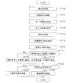
さらに、上述した車両用制動装置による作動について図3に示すフローチャートに沿って説明する。ブレーキECU17は、そのフローチャートに沿ったプログラムを所定の短時間(制御周期)毎に実行する。
ブレーキECU17は、ステップS102において、ストロークセンサ11cからブレーキペダル11の操作量を取得する。ステップS102は、上述した操作量取得部17aに相当するステップである。なお、ステップS102において、他のシステム(例えば、衝突を検知した場合、自動的に制動力を発生させて衝突を防止するプリクラッシュシステム)から要求制動力(または要求減速度)を取得するようにしてもよい。Further, the operation of the vehicle braking device described above will be described with reference to the flowchart shown in FIG. The
In step S102, the
ブレーキECU17は、ステップS104において、操作量(ストローク)または他のシステムからの要求制動力に応じた目標液圧を導出する。ステップS104は、上述した目標液圧導出部17bに相当するステップである。
ブレーキECU17は、ステップS106において、ステップS104によって導出された目標液圧から第一不感帯を導出(設定)する。ステップS106は、上述した第一不感帯設定部17c1に相当するステップである。
ブレーキECU17は、ステップS108において、ステップS104によって導出された目標液圧から第二不感帯を導出(設定)する。ステップS108は、上述した第二不感帯設定部17c2に相当するステップである。
ブレーキECU17は、ステップS110において、実液圧であるサーボ圧を圧力センサ26aから取得する。ステップS110は、上述した実液圧取得部17fに相当するステップである。
ブレーキECU17は、ステップS112において、ステップS104によって導出された目標液圧から目標液圧勾配を導出する。ステップS112は、上述した目標液圧勾配導出部17eに相当するステップである。In step S104, the
In step S106, the
In step S108, the
In step S110, the
In step S112, the
ブレーキECU17は、ステップS114において、ステップS110によって取得された実液圧から実液圧勾配を導出する。ステップS114は、上述した実液圧勾配導出部17gに相当するステップである。 In step S114, the
ブレーキECU17は、ステップS116において、目標液圧および実液圧の少なくとも何れか一方の変化から、不感帯の変更の要否を判定する。具体的には、ブレーキECU17は、ステップS112で導出した目標液圧勾配と、ステップS114で導出した実液圧勾配とから、不感帯を第二不感帯に切り換える必要があるか否かを判定する。ステップS116は、上述した判定部17hに相当するステップである。ブレーキECU17は、不感帯の変更が必要でない場合に、プログラムをステップS118に進め、不感帯を、先に導出した第一不感帯に設定する。ブレーキECU17は、不感帯の変更が必要である場合に、プログラムをステップS120に進め、不感帯を、先に導出した第二不感帯に設定する。 In step S116, the
ブレーキECU17は、ステップS122において、ステップS110で取得した実液圧が、ステップS118またはステップS120で設定された不感帯内であるか否かを判定する。ブレーキECU17は、実液圧が不感帯内である場合、プログラムをステップS124に進め、実液圧が不感帯内でない場合、プログラムをステップS126に進める。
ブレーキECU17は、ステップS124において、上述した抑制制御を実施する。ブレーキECU17は、ステップS126において、上述した追従制御を実施する。In step S122, the
In step S124, the
さらに、上述した車両用制動装置による作動について図4に示すタイムチャートに沿って説明する。
時刻t1において、ブレーキペダル11の踏み込みが開始される。時刻t1から時刻t2までの間(目標液圧の増加中)において、ブレーキペダル11は踏込中であり、時刻t2から時刻t3までの間において、ブレーキペダル11は所定の操作量にて保持されている(目標液圧の保持中)。さらに、時刻t3において、ブレーキペダル11の踏み戻しが開始される。時刻t3から時刻t4までの間(目標液圧の減少中)において、ブレーキペダル11は踏み戻し中であり、時刻t4以降において、ブレーキペダル11は踏み戻された状態(踏まれていない状態)である。
なお、目標液圧を太い実線で、第一不感帯を細い破線で、第二不感帯を細い一点鎖線で、本発明に係る実液圧を太い一点鎖線で、比較例に係る実液圧を太い破線で示している。Further, the operation of the above-described vehicle braking device will be described along the time chart shown in FIG.
At time t1, depression of the
The target hydraulic pressure is indicated by a thick solid line, the first dead zone is indicated by a thin broken line, the second dead zone is indicated by a thin dashed line, the actual hydraulic pressure according to the present invention is indicated by a thick dashed line, and the actual hydraulic pressure according to the comparative example is indicated by a thick broken line. Is shown.
比較例において目標液圧の増加中は、不感帯が第一不感帯に設定されているため、実液圧が第一下限閾値を下回った後、増圧されて第一上限閾値に達するまでの間に、実液圧はP1だけ増圧される。 In the comparative example, while the target hydraulic pressure is increasing, the dead zone is set to the first dead zone, so after the actual hydraulic pressure falls below the first lower limit threshold, the pressure is increased and reaches the first upper limit threshold. The actual fluid pressure is increased by P1.
これに対して、本発明によれば、目標液圧の増加中は、不感帯が第二不感帯に設定され、特に上限閾値は第一上限閾値より目標液圧に近づいた値である第二上限閾値に設定されている。よって、実液圧が第一下限閾値を下回った後、増圧されて第二上限閾値に達するまでの間に、実液圧はP1より小さいP2だけ増圧される。すなわち、通常時(実値が不感帯を通過しないことが判定されている場合)と比較して実液圧の減少を早期に開始させ、実液圧の変化量(増大量)を小さく抑制することができ、ひいて実液圧の階段状の変化を抑制することができる。 On the other hand, according to the present invention, while the target hydraulic pressure is increasing, the dead zone is set to the second dead zone, and in particular, the upper limit threshold is a value closer to the target hydraulic pressure than the first upper limit threshold. Is set to Therefore, after the actual hydraulic pressure falls below the first lower limit threshold, the actual hydraulic pressure is increased by P2 which is smaller than P1 until the actual hydraulic pressure is increased and reaches the second upper limit threshold. That is, the actual fluid pressure starts to decrease at an early stage and the change amount (increase amount) of the actual fluid pressure is suppressed to a small value compared to the normal time (when it is determined that the actual value does not pass through the dead zone). As a result, a step-like change in the actual hydraulic pressure can be suppressed.
以上のことは、目標液圧の減少中も同様であり、本発明によれば、目標液圧の減少中においては、不感帯が第二不感帯に設定され、特に下限閾値は第一下限閾値より目標液圧に近づいた値である第二下限閾値に設定されている。よって、実液圧が第一上限閾値を上回った後、減圧されて第二下限閾値に達するまでの間に、実液圧はP3より小さいP4だけ減圧される。すなわち、通常時(実値が不感帯を通過しないことが判定されている場合)と比較して実液圧の増加を早期に開始させ、実液圧の変化量(減少量)を小さく抑制することができ、ひいて実液圧の階段状の変化を抑制することができる。なお、P3は、下限閾値が第一下限閾値である場合(通常時である場合)の実液圧の減圧量である。 The above is the same when the target hydraulic pressure is decreasing. According to the present invention, the dead zone is set to the second dead zone while the target hydraulic pressure is decreasing. It is set to the second lower limit threshold which is a value approaching the hydraulic pressure. Therefore, after the actual fluid pressure exceeds the first upper limit threshold, the actual fluid pressure is reduced by P4, which is smaller than P3, until the actual fluid pressure is reduced and reaches the second lower limit threshold. That is, the increase in the actual fluid pressure is started earlier than in the normal case (when it is determined that the actual value does not pass through the dead zone), and the change amount (decrease amount) in the actual fluid pressure is suppressed to be small. As a result, a step-like change in the actual hydraulic pressure can be suppressed. In addition, P3 is the amount of pressure reduction of the actual hydraulic pressure when the lower limit threshold is the first lower limit threshold (when normal).
上述した説明から明らかなように、本実施形態に係る車両用制動装置は、車輪に付与する制動力に係るサーボ圧(物理量)をその目標液圧(目標値)に制御すべく、目標液圧よりも小さい下限閾値と目標液圧よりも大きい上限閾値との間を不感帯として、実液圧(物理量の実値)が不感帯外の値である場合に、実液圧を目標液圧に追従させる追従制御を行い、実液圧が不感帯内の値である場合に、実液圧の変化を抑制する抑制制御を行う。車両用制動装置は、目標液圧(目標値)の増加中に、実液圧(実値)が上限閾値Puを上回って不感帯を通過するか否かを判定する判定部17hと、判定部17hによって実液圧が不感帯を通過することが判定されている場合に、判定部17hによって実液圧が不感帯を通過しないことが判定されている場合に設定する上限閾値Puである第一上限閾値よりも、目標液圧に近づけた第二上限閾値を、上限閾値Puとして設定する設定部17cと、を備えている。 As is clear from the above description, the vehicle braking apparatus according to the present embodiment is configured to control the servo pressure (physical quantity) related to the braking force applied to the wheels to the target hydraulic pressure (target value). When the actual fluid pressure (actual value of physical quantity) is a value outside the dead zone, the actual fluid pressure is made to follow the target fluid pressure between the lower limit threshold value smaller than the upper limit threshold value greater than the target fluid pressure. Follow-up control is performed, and when the actual fluid pressure is a value within the dead zone, suppression control for suppressing a change in the actual fluid pressure is performed. The vehicle braking device includes a
これによれば、車両用制動装置は、目標液圧が増加している場合であって、実液圧が上限閾値Puを上回って不感帯を通過することが判定されている場合に、実液圧が不感帯を通過しないことが判定されている場合(例えば通常時)に設定する上限閾値Puである第一上限閾値よりも、目標液圧に近づけた第二上限閾値を、上限閾値Pu(すなわち実液圧減少を開始させる閾値)として設定する。これにより、実液圧の減少を通常時と比較して早期に開始させ、実液圧の変化量(増大量)を小さく抑制することができ、ひいて実液圧の階段状の変化を抑制することができる。したがって、制動時におけるドライバの違和感を抑制することができる車両用制動装置を提供することができる。 According to this, when the target hydraulic pressure is increased and the actual hydraulic pressure exceeds the upper limit threshold Pu and it is determined that the actual hydraulic pressure passes through the dead zone, Is determined not to pass through the dead zone (for example, at normal time), the second upper limit threshold closer to the target hydraulic pressure than the first upper limit threshold Pu that is set as the upper limit threshold Pu is set to the upper limit threshold Pu (that is, actual It is set as the threshold value for starting the hydraulic pressure reduction. As a result, the decrease in the actual fluid pressure can be started earlier compared to the normal time, and the change amount (increase amount) in the actual fluid pressure can be suppressed to a small level, which in turn suppresses the stepwise change in the actual fluid pressure. can do. Therefore, it is possible to provide a vehicle braking device that can suppress the driver's uncomfortable feeling during braking.
また、判定部17hは、目標液圧の減少中に、実液圧が下限閾値Plを下回って不感帯を通過するか否かを判定し、設定部17cは、判定部17hによって実液圧が不感帯を通過することが判定されている場合に、上記第一下限閾値よりも、目標値に近づけた第二下限閾値を、下限閾値Plとして設定する。
これによれば、車両用制動装置は、目標液圧が減少している場合であって、実液圧が不感帯を通過することが判定されている場合に、不感帯の下限閾値(すなわち実液圧増加を開始させる閾値)を、実液圧が不感帯を通過しないことが判定されている場合(例えば通常時)に設定されている第一下限閾値よりも目標液圧に近づけた第二下限閾値に変更している。これにより、実液圧の増大を通常時と比較して早期に開始させ、実液圧の変化量(減少量)を小さく抑制することができ、ひいて実液圧の階段状の変化を抑制することができる。Further, the
According to this, when the target hydraulic pressure is decreasing and it is determined that the actual hydraulic pressure passes through the dead zone, the vehicular braking device can detect the lower limit threshold of the dead zone (that is, the actual hydraulic pressure). The threshold value for starting the increase) is set to the second lower limit threshold value that is closer to the target hydraulic pressure than the first lower limit threshold value that is set when the actual hydraulic pressure does not pass through the dead zone (for example, normal time). It has changed. As a result, the increase in the actual fluid pressure can be started earlier compared to the normal time, and the change amount (decrease amount) in the actual fluid pressure can be suppressed to a small level, thereby suppressing the stepwise change in the actual fluid pressure. can do.
また、設定部17cは、判定部17hによって実液圧が不感帯を通過することが判定され、かつ、目標液圧の単位時間当たりの変化量が第一判定値よりも小さい場合に、不感帯の変更を実施する。
これによれば、不感帯の第二不感帯への変更を確実に行うことができる。The
According to this, the dead zone can be reliably changed to the second dead zone.
また、判定部17hは、目標液圧の増加中または減少中に、目標液圧の単位時間当たりの変化量と、実液圧の単位時間当たりの変化量との差である変化量差が第三判定値よりも大きい場合に、実値が不感帯を通過することを判定する。
これによれば、不感帯の第二不感帯への変更の要否判定を確実に行うことができる。In addition, the
According to this, it is possible to reliably determine whether or not to change the dead zone to the second dead zone.
さらに、判定部17hは、目標液圧の増加中または減少中に、目標液圧の単位時間当たりの変化量と、実値の単位時間当たりの変化量との差である変化量差が第四判定値よりも小さい場合に、実液圧が不感帯を通過しないことを判定する。第四判定値は、第三判定値よりも小さい。
これによれば、制御ハンチングを抑制することができる。Further, the
According to this, control hunting can be suppressed.
また、判定部17hは、目標値の増加中または減少中に、実液圧が一定である状態が所定時間継続した場合に、実液圧が不感帯を通過することを判定する。
これによれば、不感帯の第二不感帯への変更の要否判定を確実に行うことができる。In addition, the
According to this, it is possible to reliably determine whether or not to change the dead zone to the second dead zone.
なお、上述した実施形態において、本発明を、液圧式ブースタに適用するようにしたが、電動モータなどを駆動源とし、かつブレーキ操作部材にかかる操作力を倍力する電動式ブースタに適用するようにしてもよい。 In the above-described embodiment, the present invention is applied to a hydraulic booster. However, the present invention is applied to an electric booster that uses an electric motor or the like as a drive source and boosts an operation force applied to a brake operation member. It may be.
11…ブレーキペダル、12…マスタシリンダ、13…ストロークシミュレータ部、14…リザーバ、15…倍力機構(液圧発生装置)、15a…レギュレータ、15b…圧力供給装置(駆動部)、15b1…リザーバ(低圧力源)、15b2…アキュムレータ(高圧力源)、15b6…減圧弁(減圧電磁弁)、15b7…増圧弁(増圧電磁弁)、16…アクチュエータ、17…ブレーキECU、17a…操作量取得部、17b…目標液圧導出部、17c…設定部、17c1…第一不感帯設定部(設定部)、17c2…第二不感帯設定部(設定部)、17e…目標液圧勾配導出部、17f…実液圧取得部、17g…実液圧勾配導出部、17h…判定部、17i…制御部、A…液圧制動力発生装置(車両用制動装置)、WC…ホイールシリンダ。
DESCRIPTION OF
Claims (7)
Translated fromJapanese前記目標値の増加中に、前記実値が前記上限閾値を上回って前記不感帯を通過するか否かを判定する判定部と、
前記判定部によって前記実値が前記不感帯を通過することが判定されている場合に、前記判定部によって前記実値が前記不感帯を通過しないことが判定されている場合に設定する前記上限閾値である第一上限閾値よりも、前記目標値に近づけた第二上限閾値を、前記上限閾値として設定する設定部と、
を備えていることを特徴とする車両用制動装置。In order to control the physical quantity related to the braking force applied to the wheel to the target value, the actual value of the physical quantity is the dead band between a lower limit threshold value smaller than the target value and an upper limit threshold value larger than the target value. Vehicle that performs follow-up control that causes the actual value to follow the target value when the value is outside, and performs suppression control that suppresses a change in the actual value when the actual value is a value within the dead zone. Brake device for
A determination unit that determines whether the actual value exceeds the upper threshold and passes through the dead zone during the increase of the target value;
When the determination unit determines that the actual value passes through the dead band, the upper limit threshold is set when the determination unit determines that the actual value does not pass through the dead band. A setting unit that sets, as the upper limit threshold, a second upper limit threshold that is closer to the target value than the first upper limit threshold;
A vehicle braking device comprising:
前記設定部は、前記判定部によって前記実値が前記不感帯を通過することが判定されている場合に、前記判定部によって前記実値が前記不感帯を通過しないことが判定されている場合に設定する前記下限閾値である第一下限閾値よりも、前記目標値に近づけた第二下限閾値を、前記下限閾値として設定する請求項1記載の車両用制動装置。The determination unit determines whether the actual value falls below the lower limit threshold and passes the dead zone while the target value is decreasing.
The setting unit is set when the determination unit determines that the actual value does not pass through the dead band when the determination unit determines that the actual value passes through the dead band. The vehicle braking device according to claim 1, wherein a second lower limit threshold that is closer to the target value than the first lower limit threshold that is the lower limit threshold is set as the lower limit threshold.
前記第二判定値は、前記第一判定値よりも大きい請求項3記載の車両用制動装置。When the amount of change per unit time of the target value is larger than a second determination value, the setting unit changes the second upper limit threshold value to the first upper limit threshold value and changes the second lower limit threshold value to the first lower limit threshold value. Implement at least one of the changes to the lower threshold,
The vehicle braking device according to claim 3, wherein the second determination value is larger than the first determination value.
前記第四判定値は、前記第三判定値よりも小さい請求項5記載の車両用制動装置。The determination unit determines whether a change amount difference that is a difference between a change amount per unit time of the target value and a change amount per unit time of the actual value is a fourth determination while the target value is increasing or decreasing. If less than the value, determine that the actual value does not pass through the dead zone;
The vehicle braking device according to claim 5, wherein the fourth determination value is smaller than the third determination value.
The determination unit determines that the actual value passes through the dead zone when the state in which the actual value is constant continues for a predetermined time while the target value is increasing or decreasing. Item 7. The vehicle braking device according to any one of items 6 to 6.
Priority Applications (5)
| Application Number | Priority Date | Filing Date | Title |
|---|---|---|---|
| JP2015231367AJP6371271B2 (en) | 2015-11-27 | 2015-11-27 | Braking device for vehicle |
| US15/773,827US10793125B2 (en) | 2015-11-27 | 2016-11-25 | Vehicle braking device |
| DE112016005418.1TDE112016005418T5 (en) | 2015-11-27 | 2016-11-25 | VEHICLE BRAKING SYSTEMS |
| CN201680068068.0ACN108290556B (en) | 2015-11-27 | 2016-11-25 | vehicle brake |
| PCT/JP2016/085065WO2017090755A1 (en) | 2015-11-27 | 2016-11-25 | Vehicle braking device |
Applications Claiming Priority (1)
| Application Number | Priority Date | Filing Date | Title |
|---|---|---|---|
| JP2015231367AJP6371271B2 (en) | 2015-11-27 | 2015-11-27 | Braking device for vehicle |
Publications (2)
| Publication Number | Publication Date |
|---|---|
| JP2017095025A JP2017095025A (en) | 2017-06-01 |
| JP6371271B2true JP6371271B2 (en) | 2018-08-08 |
Family
ID=58763532
Family Applications (1)
| Application Number | Title | Priority Date | Filing Date |
|---|---|---|---|
| JP2015231367AActiveJP6371271B2 (en) | 2015-11-27 | 2015-11-27 | Braking device for vehicle |
Country Status (5)
| Country | Link |
|---|---|
| US (1) | US10793125B2 (en) |
| JP (1) | JP6371271B2 (en) |
| CN (1) | CN108290556B (en) |
| DE (1) | DE112016005418T5 (en) |
| WO (1) | WO2017090755A1 (en) |
Families Citing this family (6)
| Publication number | Priority date | Publication date | Assignee | Title |
|---|---|---|---|---|
| JP6371271B2 (en)* | 2015-11-27 | 2018-08-08 | 株式会社アドヴィックス | Braking device for vehicle |
| JP6487831B2 (en)* | 2015-11-27 | 2019-03-20 | 株式会社アドヴィックス | Hydraulic control device |
| KR102065270B1 (en)* | 2018-08-27 | 2020-01-10 | 현대제철 주식회사 | Brake device for vehicle |
| DE102018217806A1 (en)* | 2018-10-18 | 2020-04-23 | Robert Bosch Gmbh | Method for operating a brake system of a motor vehicle, brake system, motor vehicle |
| CN112660195B (en)* | 2021-01-04 | 2023-03-28 | 中车青岛四方车辆研究所有限公司 | Pressure control compensation method and device for locomotive brake control system |
| CN116466566A (en)* | 2023-04-20 | 2023-07-21 | 大唐东北电力试验研究院有限公司 | PID control system and method based on intelligent judgment of control deviation |
Family Cites Families (19)
| Publication number | Priority date | Publication date | Assignee | Title |
|---|---|---|---|---|
| JP4207699B2 (en) | 2003-07-18 | 2009-01-14 | トヨタ自動車株式会社 | Fluid pressure control device and fluid pressure control method |
| JP4780948B2 (en)* | 2004-11-15 | 2011-09-28 | トヨタ自動車株式会社 | Brake hydraulic pressure control device |
| JP4466696B2 (en) | 2007-08-10 | 2010-05-26 | トヨタ自動車株式会社 | Brake device, brake control device, and brake control method |
| JP5780060B2 (en)* | 2011-08-30 | 2015-09-16 | トヨタ自動車株式会社 | Brake control device for vehicle |
| JP2013111998A (en) | 2011-11-25 | 2013-06-10 | Toyota Motor Corp | Brake control device for vehicle |
| US20150329108A1 (en)* | 2012-12-11 | 2015-11-19 | Toyota Jidosha Kabushiki Kaisha | Driving assistance device and driving assistance method |
| JP6025762B2 (en) | 2014-01-31 | 2016-11-16 | 株式会社アドヴィックス | Vehicle control device |
| JP6520506B2 (en)* | 2014-09-03 | 2019-05-29 | 株式会社デンソー | Vehicle travel control system |
| JP6250892B2 (en)* | 2015-01-30 | 2017-12-20 | 株式会社アドヴィックス | Braking device for vehicle |
| JP6325493B2 (en)* | 2015-07-29 | 2018-05-16 | 株式会社アドヴィックス | Braking device for vehicle |
| CN108137008B (en)* | 2015-09-09 | 2021-03-26 | Ntn株式会社 | Electric brake device |
| JP6371268B2 (en)* | 2015-11-24 | 2018-08-08 | 株式会社アドヴィックス | Braking device for vehicle |
| JP6371271B2 (en)* | 2015-11-27 | 2018-08-08 | 株式会社アドヴィックス | Braking device for vehicle |
| CN109154820B (en)* | 2016-05-16 | 2021-10-22 | 本田技研工业株式会社 | Vehicle control system, vehicle control method, and storage medium |
| JP6399038B2 (en)* | 2016-05-18 | 2018-10-03 | トヨタ自動車株式会社 | Hybrid car |
| JP6372532B2 (en)* | 2016-09-05 | 2018-08-15 | トヨタ自動車株式会社 | Electric vehicle and control method of electric vehicle |
| JP6530359B2 (en)* | 2016-09-09 | 2019-06-12 | 株式会社アドヴィックス | Vehicle braking system |
| JP2018079728A (en)* | 2016-11-14 | 2018-05-24 | トヨタ自動車株式会社 | Hybrid vehicle |
| JP6577444B2 (en)* | 2016-11-24 | 2019-09-18 | トヨタ自動車株式会社 | Brake control device for vehicle |
- 2015
- 2015-11-27JPJP2015231367Apatent/JP6371271B2/enactiveActive
- 2016
- 2016-11-25DEDE112016005418.1Tpatent/DE112016005418T5/enactivePending
- 2016-11-25WOPCT/JP2016/085065patent/WO2017090755A1/ennot_activeCeased
- 2016-11-25USUS15/773,827patent/US10793125B2/enactiveActive
- 2016-11-25CNCN201680068068.0Apatent/CN108290556B/enactiveActive
Also Published As
| Publication number | Publication date |
|---|---|
| WO2017090755A1 (en) | 2017-06-01 |
| DE112016005418T5 (en) | 2018-08-02 |
| CN108290556A (en) | 2018-07-17 |
| US20180319383A1 (en) | 2018-11-08 |
| CN108290556B (en) | 2020-08-28 |
| US10793125B2 (en) | 2020-10-06 |
| JP2017095025A (en) | 2017-06-01 |
Similar Documents
| Publication | Publication Date | Title |
|---|---|---|
| JP6371268B2 (en) | Braking device for vehicle | |
| JP6371271B2 (en) | Braking device for vehicle | |
| JP6434395B2 (en) | Hydraulic control device | |
| JP6595417B2 (en) | Braking device for vehicle | |
| JP6487831B2 (en) | Hydraulic control device | |
| JP6654391B2 (en) | Hydraulic pressure control device | |
| WO2017038626A1 (en) | Abnormality detection device | |
| JP6378145B2 (en) | Anomaly detection device | |
| JP6470703B2 (en) | Braking device for vehicle | |
| JP6426579B2 (en) | Vehicle braking system | |
| JP6250898B2 (en) | Hydraulic pressure generator | |
| JP6781580B2 (en) | Vehicle braking device | |
| WO2020138142A1 (en) | Braking control device | |
| WO2017069243A1 (en) | Liquid pressure control device | |
| JP2019189152A (en) | Brake device for vehicle |
Legal Events
| Date | Code | Title | Description |
|---|---|---|---|
| A621 | Written request for application examination | Free format text:JAPANESE INTERMEDIATE CODE: A621 Effective date:20171006 | |
| TRDD | Decision of grant or rejection written | ||
| A01 | Written decision to grant a patent or to grant a registration (utility model) | Free format text:JAPANESE INTERMEDIATE CODE: A01 Effective date:20180619 | |
| A61 | First payment of annual fees (during grant procedure) | Free format text:JAPANESE INTERMEDIATE CODE: A61 Effective date:20180712 | |
| R150 | Certificate of patent or registration of utility model | Ref document number:6371271 Country of ref document:JP Free format text:JAPANESE INTERMEDIATE CODE: R150 |